Computer memory and Computer data storage types |
---|
Volatile |
Non-volatile |
The Selectron was an early form of digital computer memory developed by Jan A. Rajchman and his group at the Radio Corporation of America (RCA) under the direction of Vladimir K. Zworykin. It was a vacuum tube that stored digital data as electrostatic charges using technology similar to the Williams tube storage device. The team was never able to produce a commercially viable form of Selectron before magnetic-core memory became almost universal.
Development of Selectron started in 1946 at the behest of John von Neumann of the Institute for Advanced Study, [1] who was in the midst of designing the IAS machine and was looking for a new form of high-speed memory.
RCA's original design concept had a capacity of 4096 bits, with a planned production of 200 by the end of 1946. They found the device to be much more difficult to build than expected, and they were still not available by the middle of 1948. As development dragged on, the IAS machine was forced to switch to Williams tubes for storage, and the primary customer for Selectron disappeared. RCA lost interest in the design and assigned its engineers to improve televisions [2]
A contract from the US Air Force led to a re-examination of the device in a 256-bit form. Rand Corporation took advantage of this project to switch their own IAS machine, the JOHNNIAC, to this new version of the Selectron, using 80 of them to provide 512 40-bit words of main memory. They signed a development contract with RCA to produce enough tubes for their machine at a projected cost of $500 per tube ($6332 in 2023). [2]
Around this time IBM expressed an interest in the Selectron as well, but this did not lead to additional production. As a result, RCA assigned their engineers to color television development, and put the Selectron in the hands of "the mothers-in-law of two deserving employees (the Chairman of the Board and the President)." [2]
Both the Selectron and the Williams tube were superseded in the market by the compact and cost-effective magnetic-core memory, in the early 1950s. The JOHNNIAC developers had decided to switch to core even before the first Selectron-based version had been completed. [2]
The Williams tube was an example of a general class of cathode-ray tube (CRT) devices known as storage tubes.
The primary function of a conventional CRT is to display an image by lighting phosphor using a beam of electrons fired at it from an electron gun at the back of the tube. The target point of the beam is steered around the front of the tube though the use of deflection magnets or electrostatic plates.
Storage tubes were based on CRTs, sometimes unmodified. They relied on two normally undesirable principles of phosphor used in the tubes. One was that when electrons from the CRT's electron gun struck the phosphor to light it, some of the electrons "stuck" to the tube and caused a localized static electric charge to build up. This charge opposed any future electrons flowing into that area from the gun, and caused differences in brightness. The second was that the phosphor, like many materials, also released new electrons when struck by an electron beam, a process known as secondary emission. [3]
Secondary emission had the useful feature that the rate of electron release was significantly non-linear. When a voltage was applied that crossed a certain threshold, the rate of emission increased dramatically. This caused the lit spot to rapidly decay, which also caused any stuck electrons to be released as well. Visual systems used this process to erase the display, causing any stored pattern to rapidly fade. For computer uses it was the rapid release of the stuck charge that allowed it to be used for storage. [4]
In the Williams tube, the electron gun at the back of an otherwise typical CRT is used to deposit a series of small patterns representing a 1 or 0 on the phosphor in a grid representing memory addresses. To read the display, the beam scanned the tube again, this time set to a voltage very close to that of the secondary emission threshold. The patterns were selected to bias the tube very slightly positive or negative. When the stored static electricity was added to the voltage of the beam, the total voltage either crossed the secondary emission threshold or didn't. If it crossed the threshold, a burst of electrons was released as the dot decayed. This burst was read capacitively on a metal plate placed just in front of the display side of the tube. [4]
There were four general classes of storage tubes; the "surface redistribution type" represented by the Williams tube, the "barrier grid" system, which was unsuccessfully commercialized by RCA as the Radechon tube, the "sticking potential" type which was not used commercially, and the "holding beam" concept, of which the Selectron is a specific example. [5]
In the most basic implementation, the holding beam tube uses three electron guns; one for writing, one for reading, and a third "holding gun" that maintains the pattern. The general operation is very similar to the Williams tube in concept. The main difference was the holding gun, which fired continually and unfocussed so it covered the entire storage area on the phosphor. This caused the phosphor to be continually charged to a selected voltage, somewhat below that of the secondary emission threshold. [6]
Writing was accomplished by firing the writing gun at low voltage in a fashion similar to the Williams tube, adding a further voltage to the phosphor. Thus the storage pattern was the slight difference between two voltages stored on the tube, typically only a few tens of volts different. [6] In comparison, the Williams tube used much higher voltages, producing a pattern that could only be stored for a short period before it decayed below readability.
Reading was accomplished by scanning the reading gun across the storage area. This gun was set to a voltage that would cross the secondary emission threshold for the entire display. If the scanned area held the holding gun potential a certain number of electrons would be released, if it held the writing gun potential the number would be higher. The electrons were read on a grid of fine wires placed behind the display, making the system entirely self-contained. In contrast, the Williams tube's read plate was in front of the tube, and required continual mechanical adjustment to work properly. [6] The grid also had the advantage of breaking the display into individual spots without requiring the tight focus of the Williams system.
General operation was the same as the Williams system, but the holding concept had two major advantages. One was that it operated at much lower voltage differences and was thus able to safely store data for a longer period of time. The other was that the same deflection magnet drivers could be sent to several electron guns to produce a single larger device with no increase in complexity of the electronics.
The Selectron further modified the basic holding gun concept through the use of individual metal eyelets that were used to store additional charge in a more predictable and long-lasting fashion.
Unlike a CRT where the electron gun is a single point source consisting of a filament and single charged accelerator, in the Selectron the "gun" is a plate and the accelerator is a grid of wires (thus borrowing some design notes from the barrier-grid tube). Switching circuits allow voltages to be applied to the wires to turn them on or off. When the gun fires through the eyelets, it is slightly defocussed. Some of the electrons strike the eyelet and deposit a charge on it.
The original 4096-bit Selectron [7] was a 10-inch-long (250 mm) by 3-inch-diameter (76 mm) vacuum tube configured as 1024 by 4 bits. It had an indirectly heated cathode running up the middle, surrounded by two separate sets of wires — one radial, one axial — forming a cylindrical grid array, and finally a dielectric storage material coating on the inside of four segments of an enclosing metal cylinder, called the signal plates. The bits were stored as discrete regions of charge on the smooth surfaces of the signal plates.
The two sets of orthogonal grid wires were normally "biased" slightly positive, so that the electrons from the cathode were accelerated through the grid to reach the dielectric. The continuous flow of electrons allowed the stored charge to be continuously regenerated by the secondary emission of electrons. To select a bit to be read from or written to, all but two adjacent wires on each of the two grids were biased negative, allowing current to flow to the dielectric at one location only.
In this respect, the Selectron works in the opposite sense of the Williams tube. In the Williams tube, the beam is continually scanning in a read/write cycle which is also used to regenerate data. In contrast, the Selectron is almost always regenerating the entire tube, only breaking this periodically to do actual reads and writes. This not only made operation faster due to the lack of required pauses but also meant the data was much more reliable as it was constantly refreshed.
Writing was accomplished by selecting a bit, as above, and then sending a pulse of potential, either positive or negative, to the signal plate. With a bit selected, electrons would be pulled onto (with a positive potential) or pushed from (negative potential) the dielectric. When the bias on the grid was dropped, the electrons were trapped on the dielectric as a spot of static electricity.
To read from the device, a bit location was selected and a pulse sent from the cathode. If the dielectric for that bit contained a charge, the electrons would be pushed off the dielectric and read as a brief pulse of current in the signal plate. No such pulse meant that the dielectric must not have held a charge.
The smaller capacity 256-bit (128 by 2 bits) "production" device [8] was in a similar vacuum-tube envelope. It was built with two storage arrays of discrete "eyelets" on a rectangular plate, separated by a row of eight cathodes. The pin count was reduced from 44 for the 4096-bit device down to 31 pins and two coaxial signal output connectors. This version included visible green phosphors in each eyelet[ citation needed ] so that the bit status could also be read by eye.
A cathode-ray tube (CRT) is a vacuum tube containing one or more electron guns, which emit electron beams that are manipulated to display images on a phosphorescent screen. The images may represent electrical waveforms on an oscilloscope, a frame of video on an analog television set (TV), digital raster graphics on a computer monitor, or other phenomena like radar targets. A CRT in a TV is commonly called a picture tube. CRTs have also been used as memory devices, in which case the screen is not intended to be visible to an observer. The term cathode ray was used to describe electron beams when they were first discovered, before it was understood that what was emitted from the cathode was a beam of electrons.
A vacuum tube, electron tube, valve, or tube is a device that controls electric current flow in a high vacuum between electrodes to which an electric potential difference has been applied.
The Williams tube, or the Williams–Kilburn tube named after inventors Freddie Williams and Tom Kilburn, is an early form of computer memory. It was the first random-access digital storage device, and was used successfully in several early computers.
In particle physics, secondary emission is a phenomenon where primary incident particles of sufficient energy, when hitting a surface or passing through some material, induce the emission of secondary particles. The term often refers to the emission of electrons when charged particles like electrons or ions in a vacuum tube strike a metal surface; these are called secondary electrons. In this case, the number of secondary electrons emitted per incident particle is called secondary emission yield. If the secondary particles are ions, the effect is termed secondary ion emission. Secondary electron emission is used in photomultiplier tubes and image intensifier tubes to amplify the small number of photoelectrons produced by photoemission, making the tube more sensitive. It also occurs as an undesirable side effect in electronic vacuum tubes when electrons from the cathode strike the anode, and can cause parasitic oscillation.
Video camera tubes were devices based on the cathode-ray tube that were used in television cameras to capture television images, prior to the introduction of charge-coupled device (CCD) image sensors in the 1980s. Several different types of tubes were in use from the early 1930s, and as late as the 1990s.
A field-emission display (FED) is a flat panel display technology that uses large-area field electron emission sources to provide electrons that strike colored phosphor to produce a color image. In a general sense, an FED consists of a matrix of cathode ray tubes, each tube producing a single sub-pixel, grouped in threes to form red-green-blue (RGB) pixels. FEDs combine the advantages of CRTs, namely their high contrast levels and very fast response times, with the packaging advantages of LCD and other flat-panel technologies. They also offer the possibility of requiring less power, about half that of an LCD system. FEDs can also be made transparent.
Storage tubes are a class of cathode-ray tubes (CRTs) that are designed to hold an image for a long period of time, typically as long as power is supplied to the tube.
Direct-view bistable storage tube (DVBST) was an acronym used by Tektronix to describe their line of storage tubes. These were cathode ray tubes (CRT) that stored information written to them using an analog technique inherent in the CRT and based upon the secondary emission of electrons from the phosphor screen itself. The resulting image was visible in the continuously glowing patterns on the face of the CRT.
The penetron, short for penetration tube, is a type of limited-color television used in some military applications. Unlike a conventional color television, the penetron produces a limited color gamut, typically two colors and their combination. Penetrons, and other military-only cathode ray tubes (CRTs), have been replaced by LCDs in modern designs.
Regenerative capacitor memory is a type of computer memory that uses the electrical property of capacitance to store the bits of data. Because the stored charge slowly leaks away, these memories must be periodically regenerated to prevent data loss.
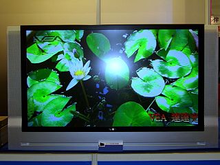
Large-screen television technology developed rapidly in the late 1990s and 2000s. Prior to the development of thin-screen technologies, rear-projection television was standard for larger displays, and jumbotron, a non-projection video display technology, was used at stadiums and concerts. Various thin-screen technologies are being developed, but only liquid crystal display (LCD), plasma display (PDP) and Digital Light Processing (DLP) have been publicly released. Recent technologies like organic light-emitting diode (OLED) as well as not-yet-released technologies like surface-conduction electron-emitter display (SED) or field emission display (FED) are in development to supersede earlier flat-screen technologies in picture quality.
A vector monitor, vector display, or calligraphic display is a display device used for computer graphics up through the 1970s. It is a type of CRT, similar to that of an early oscilloscope. In a vector display, the image is composed of drawn lines rather than a grid of glowing pixels as in raster graphics. The electron beam follows an arbitrary path, tracing the connected sloped lines rather than following the same horizontal raster path for all images. The beam skips over dark areas of the image without visiting their points.
Mellon optical memory was an early form of computer memory invented at the Mellon Institute in 1951. The device used a combination of photoemissive and phosphorescent materials to produce a "light loop" between two surfaces. The presence or lack of light, detected by a photocell, represented a one or zero. Although promising, the system was rendered obsolete with the introduction of magnetic-core memory in the early 1950s. It appears that the system was never used in production.
The inductive output tube (IOT) or klystrode is a variety of linear-beam vacuum tube, similar to a klystron, used as a power amplifier for high frequency radio waves. It evolved in the 1980s to meet increasing efficiency requirements for high-power RF amplifiers in radio transmitters. The primary commercial use of IOTs is in UHF television transmitters, where they have mostly replaced klystrons because of their higher efficiencies and smaller size. IOTs are also used in particle accelerators. They are capable of producing power output up to about 30 kW continuous and 7 MW pulsed and power gains of 20–23 dB at frequencies up to about a gigahertz.
The Chromatron is a color television cathode ray tube design invented by Nobel prize-winner Ernest Lawrence and developed commercially by Paramount Pictures, Sony, Litton Industries and others. The Chromatron offered brighter images than conventional color television systems using a shadow mask, but a host of development problems kept it from being widely used in spite of years of development. Sony eventually abandoned it in favor of their famous Trinitron system using an aperture grille.
The beam-index tube is a color television cathode ray tube (CRT) design, using phosphor stripes and active-feedback timing, rather than phosphor dots and a beam-shadowing mask as developed by RCA. Beam indexing offered much brighter pictures than shadow-mask CRTs, reducing power consumption, and as they used a single electron gun rather than three, they were easier to build and required no alignment adjustments.
This is a subdivision of the Oscilloscope article, discussing the various types and models of oscilloscopes in greater detail.
The history of the oscilloscope was fundamental to science because an oscilloscope is a device for viewing waveform oscillations, as of electrical voltage or current, in order to measure frequency and other wave characteristics. This was important in developing electromagnetic theory. The first recordings of waveforms were with a galvanometer coupled to a mechanical drawing system dating from the second decade of the 19th century. The modern day digital oscilloscope is a consequence of multiple generations of development of the oscillograph, cathode-ray tubes, analog oscilloscopes, and digital electronics.
Beam deflection tubes, sometimes known as sheet beam tubes, are vacuum tubes with an electron gun, a beam intensity control grid, a screen grid, sometimes a suppressor grid, and two electrostatic deflection electrodes on opposite sides of the electron beam that can direct the rectangular beam to either of two anodes in the same plane.
A deflection yoke is a kind of magnetic lens, used in cathode ray tubes to scan the electron beam both vertically and horizontally over the whole screen.