Cable television is a system of delivering television programming to consumers via radio frequency (RF) signals transmitted through coaxial cables, or in more recent systems, light pulses through fibre-optic cables. This contrasts with broadcast television, in which the television signal is transmitted over-the-air by radio waves and received by a television antenna ; or satellite television, in which the television signal is transmitted over-the-air by radio waves from a communications satellite and received by a satellite dish on the roof. FM radio programming, high-speed Internet, telephone services, and similar non-television services may also be provided through these cables. Analog television was standard in the 20th century, but since the 2000s, cable systems have been upgraded to digital cable operation.
Very high frequency (VHF) is the ITU designation for the range of radio frequency electromagnetic waves from 30 to 300 megahertz (MHz), with corresponding wavelengths of ten meters to one meter. Frequencies immediately below VHF are denoted high frequency (HF), and the next higher frequencies are known as ultra high frequency (UHF).

Ultra high frequency (UHF) is the ITU designation for radio frequencies in the range between 300 megahertz (MHz) and 3 gigahertz (GHz), also known as the decimetre band as the wavelengths range from one meter to one tenth of a meter. Radio waves with frequencies above the UHF band fall into the super-high frequency (SHF) or microwave frequency range. Lower frequency signals fall into the VHF or lower bands. UHF radio waves propagate mainly by line of sight; they are blocked by hills and large buildings although the transmission through building walls is strong enough for indoor reception. They are used for television broadcasting, cell phones, satellite communication including GPS, personal radio services including Wi-Fi and Bluetooth, walkie-talkies, cordless phones, satellite phones, and numerous other applications.
A satellite dish is a dish-shaped type of parabolic antenna designed to receive or transmit information by radio waves to or from a communication satellite. The term most commonly means a dish which receives direct-broadcast satellite television from a direct broadcast satellite in geostationary orbit.
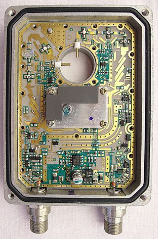
A low-noise block downconverter (LNB) is the receiving device mounted on satellite dishes used for satellite TV reception, which collects the radio waves from the dish and converts them to a signal which is sent through a cable to the receiver inside the building. Also called a low-noise block, low-noise converter (LNC), or even low-noise downconverter (LND), the device is sometimes inaccurately called a low-noise amplifier (LNA).

A whip antenna is an antenna consisting of a straight flexible wire or rod. The bottom end of the whip is connected to the radio receiver or transmitter. A whip antenna is a form of monopole antenna. The antenna is designed to be flexible so that it does not break easily, and the name is derived from the whip-like motion that it exhibits when disturbed. Whip antennas for portable radios are often made of a series of interlocking telescoping metal tubes, so they can be retracted when not in use. Longer whips, made for mounting on vehicles and structures, are made of a flexible fiberglass rod around a wire core and can be up to 11 m long.

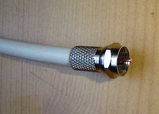
The F connector is a coaxial RF connector commonly used for "over the air" terrestrial television, cable television and universally for satellite television and cable modems, usually with RG-6/U cable or with RG-59/U cable.
An antenna tuner, a matchbox, transmatch, antenna tuning unit (ATU), antenna coupler, or feedline coupler is a device connected between a radio transmitter or receiver and its antenna to improve power transfer between them by matching the impedance of the radio to the antenna's feedline. Antenna tuners are particularly important for use with transmitters. Transmitters feed power into a resistive load, very often 50 ohms, for which the transmitter is optimally designed for power output, efficiency, and low distortion. If the load seen by the transmitter departs from this design value due to improper tuning of the antenna/feedline combination the power output will change, distortion may occur and the transmitter may overheat.
A link budget is an accounting of all of the power gains and losses that a communication signal experiences in a telecommunication system; from a transmitter, through a communication medium such as radio waves, cable, waveguide, or optical fiber, to the receiver. It is an equation giving the received power from the transmitter power, after the attenuation of the transmitted signal due to propagation, as well as the antenna gains and feedline and other losses, and amplification of the signal in the receiver or any repeaters it passes through. A link budget is a design aid, calculated during the design of a communication system to determine the received power, to ensure that the information is received intelligibly with an adequate signal-to-noise ratio. Randomly varying channel gains such as fading are taken into account by adding some margin depending on the anticipated severity of its effects. The amount of margin required can be reduced by the use of mitigating techniques such as antenna diversity or multiple-input and multiple-output (MIMO).
A television transmitter is a transmitter that is used for terrestrial (over-the-air) television broadcasting. It is an electronic device that radiates radio waves that carry a video signal representing moving images, along with a synchronized audio channel, which is received by television receivers belonging to a public audience, which display the image on a screen. A television transmitter, together with the broadcast studio which originates the content, is called a television station. Television transmitters must be licensed by governments, and are restricted to a certain frequency channel and power level. They transmit on frequency channels in the VHF and UHF bands. Since radio waves of these frequencies travel by line of sight, they are limited by the horizon to reception distances of 40–60 miles depending on the height of transmitter station.
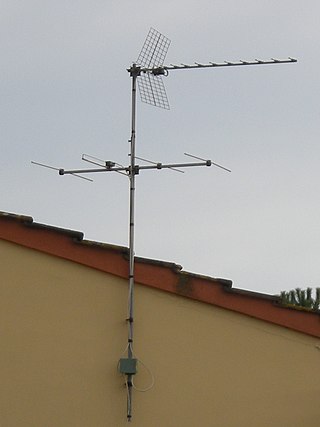
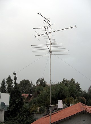
A television antenna, also called a television aerial, is an antenna specifically designed for use with a television receiver (TV) to receive terrestrial over-the-air (OTA) broadcast television signals from a television station. Terrestrial television is broadcast on frequencies from about 47 to 250 MHz in the very high frequency (VHF) band, and 470 to 960 MHz in the ultra high frequency (UHF) band in different countries.
A land mobile radio system (LMRS) is a person-to-person voice communication system consisting of two-way radio transceivers which can be stationary, mobile, or portable.
A radio transmitter or receiver is connected to an antenna which emits or receives the radio waves. The antenna feed system or antenna feed is the cable or conductor, and other associated equipment, which connects the transmitter or receiver with the antenna and makes the two devices compatible. In a radio transmitter, the transmitter generates an alternating current of radio frequency, and the feed system feeds the current to the antenna, which converts the power in the current to radio waves. In a radio receiver, the incoming radio waves excite tiny alternating currents in the antenna, and the feed system delivers this current to the receiver, which processes the signal.
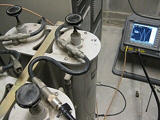
An amateur radio repeater is an electronic device that receives a weak or low-level amateur radio signal and retransmits it at a higher level or higher power, so that the signal can cover longer distances without degradation. Many repeaters are located on hilltops or on tall buildings as the higher location increases their coverage area, sometimes referred to as the radio horizon, or "footprint". Amateur radio repeaters are similar in concept to those used by public safety entities, businesses, government, military, and more. Amateur radio repeaters may even use commercially packaged repeater systems that have been adjusted to operate within amateur radio frequency bands, but more often amateur repeaters are assembled from receivers, transmitters, controllers, power supplies, antennas, and other components, from various sources.

A radio repeater is a combination of a radio receiver and a radio transmitter that receives a signal and retransmits it, so that two-way radio signals can cover longer distances. A repeater sited at a high elevation can allow two mobile stations, otherwise out of line-of-sight propagation range of each other, to communicate. Repeaters are found in professional, commercial, and government mobile radio systems and also in amateur radio.

Single-cable distribution is a satellite TV technology that enables the delivery of broadcast programming to multiple users over a single coaxial cable, and eliminates the numerous cables required to support consumer electronics devices such as twin-tuner digital video recorders (DVRs) and high-end receivers.
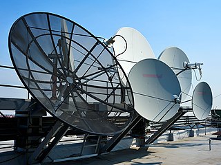
Satellite television is a service that delivers television programming to viewers by relaying it from a communications satellite orbiting the Earth directly to the viewer's location. The signals are received via an outdoor parabolic antenna commonly referred to as a satellite dish and a low-noise block downconverter.
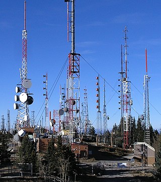
Radio is the technology of communicating using radio waves. Radio waves are electromagnetic waves of frequency between 3 hertz (Hz) and 300 gigahertz (GHz). They are generated by an electronic device called a transmitter connected to an antenna which radiates oscillating electrical energy, often characterized as a wave. They can be received by other antennas connected to a radio receiver, this is the fundamental principle of radio communication. In addition to communication, radio is used for radar, radio navigation, remote control, remote sensing, and other applications.

In electronics, an antenna amplifier is a device that amplifies an antenna signal, usually into an output with the same impedance as the input impedance. Typically 75 ohm for coaxial cable and 300 ohm for twin-lead cable.
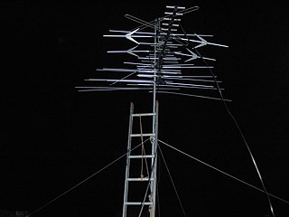
UHF television broadcasting is the use of ultra high frequency (UHF) radio for over-the-air transmission of television signals. UHF frequencies are used for both analog and digital television broadcasts. UHF channels are typically given higher channel numbers, like the US arrangement with VHF channels (initially) 1 to 13, and UHF channels (initially) numbered 14 to 83. Compared with an equivalent VHF television transmitter, to cover the same geographic area with a UHF transmitter requires a higher effective radiated power, implying a more powerful transmitter or a more complex antenna. However, the additional channels allow more broadcasters in a given region without causing objectionable mutual interference.


