
An amplifier, electronic amplifier or (informally) amp is an electronic device that can increase the magnitude of a signal. It is a two-port electronic circuit that uses electric power from a power supply to increase the amplitude of a signal applied to its input terminals, producing a proportionally greater amplitude signal at its output. The amount of amplification provided by an amplifier is measured by its gain: the ratio of output voltage, current, or power to input. An amplifier is defined as a circuit that has a power gain greater than one.
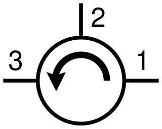
In electrical engineering, a circulator is a passive, non-reciprocal three- or four-port device that only allows a microwave or radio-frequency (RF) signal to exit through the port directly after the one it entered. Optical circulators have similar behavior. Ports are where an external waveguide or transmission line, such as a microstrip line or a coaxial cable, connects to the device. For a three-port circulator, a signal applied to port 1 only comes out of port 2; a signal applied to port 2 only comes out of port 3; a signal applied to port 3 only comes out of port 1. An ideal three-port circulator thus has the following scattering matrix:
A PIN diode is a diode with a wide, undoped intrinsic semiconductor region between a p-type semiconductor and an n-type semiconductor region. The p-type and n-type regions are typically heavily doped because they are used for ohmic contacts.

In electrical engineering, impedance is the opposition to alternating current presented by the combined effect of resistance and reactance in a circuit.
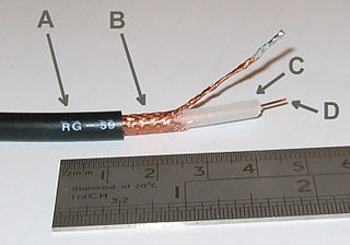
Coaxial cable, or coax, is a type of electrical cable consisting of an inner conductor surrounded by a concentric conducting shield, with the two separated by a dielectric ; many coaxial cables also have a protective outer sheath or jacket. The term coaxial refers to the inner conductor and the outer shield sharing a geometric axis.

The BNC connector is a miniature quick connect/disconnect radio frequency connector used for coaxial cable. It is designed to maintain the same characteristic impedance of the cable, with 50 ohm and 75 ohm types being made. It is usually applied for video and radio frequency connections up to about 2 GHz and up to 500 volts. The connector has a twist to lock design with two lugs in the female portion of the connector engaging a slot in the shell of the male portion. The type was introduced on military radio equipment in the 1940s and has since become widely applied in radio systems, and is a common type of video connector. Similar radio-frequency connectors differ in dimensions and attachment features, and may allow for higher voltages, higher frequencies, or three-wire connections.

In electronics, a varicap diode, varactor diode, variable capacitance diode, variable reactance diode or tuning diode is a type of diode designed to exploit the voltage-dependent capacitance of a reverse-biased p–n junction.
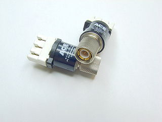
A balun is an electrical device that allows balanced and unbalanced lines to be interfaced without disturbing the impedance arrangement of either line. A balun can take many forms and may include devices that also transform impedances but need not do so. Sometimes, in the case of transformer baluns, they use magnetic coupling but need not do so. Common-mode chokes are also used as baluns and work by eliminating, rather than rejecting, common mode signals.

A gyrator is a passive, linear, lossless, two-port electrical network element proposed in 1948 by Bernard D. H. Tellegen as a hypothetical fifth linear element after the resistor, capacitor, inductor and ideal transformer. Unlike the four conventional elements, the gyrator is non-reciprocal. Gyrators permit network realizations of two-(or-more)-port devices which cannot be realized with just the four conventional elements. In particular, gyrators make possible network realizations of isolators and circulators. Gyrators do not however change the range of one-port devices that can be realized. Although the gyrator was conceived as a fifth linear element, its adoption makes both the ideal transformer and either the capacitor or inductor redundant. Thus the number of necessary linear elements is in fact reduced to three. Circuits that function as gyrators can be built with transistors and op-amps using feedback.
Capacitors and inductors as used in electric circuits are not ideal components with only capacitance or inductance. However, they can be treated, to a very good degree of approximation, as being ideal capacitors and inductors in series with a resistance; this resistance is defined as the equivalent series resistance (ESR). If not otherwise specified, the ESR is always an AC resistance, which means it is measured at specified frequencies, 100 kHz for switched-mode power supply components, 120 Hz for linear power-supply components, and at its self-resonant frequency for general-application components. Additionally, audio components may report a "Q factor", incorporating ESR among other things, at 1000 Hz.
An antenna tuner, a matchbox, transmatch, antenna tuning unit (ATU), antenna coupler, or feedline coupler is a device connected between a radio transmitter or receiver and its antenna to improve power transfer between them by matching the impedance of the radio to the antenna's feedline. Antenna tuners are particularly important for use with transmitters. Transmitters feed power into a resistive load, very often 50 ohms, for which the transmitter is optimally designed for power output, efficiency, and low distortion. If the load seen by the transmitter departs from this design value due to improper tuning of the antenna/feedline combination the power output will change, distortion may occur and the transmitter may overheat.
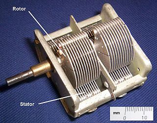
A variable capacitor is a capacitor whose capacitance may be intentionally and repeatedly changed mechanically or electronically. Variable capacitors are often used in L/C circuits to set the resonance frequency, e.g. to tune a radio, or as a variable reactance, e.g. for impedance matching in antenna tuners.

Capacitors are manufactured in many styles, forms, dimensions, and from a large variety of materials. They all contain at least two electrical conductors, called plates, separated by an insulating layer (dielectric). Capacitors are widely used as parts of electrical circuits in many common electrical devices.

In electrical engineering, a capacitor is a device that stores electrical energy by accumulating electric charges on two closely spaced surfaces that are insulated from each other. The capacitor was originally known as the condenser, a term still encountered in a few compound names, such as the condenser microphone. It is a passive electronic component with two terminals.
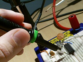
A test probe is a physical device used to connect electronic test equipment to a device under test (DUT). Test probes range from very simple, robust devices to complex probes that are sophisticated, expensive, and fragile. Specific types include test prods, oscilloscope probes and current probes. A test probe is often supplied as a test lead, which includes the probe, cable and terminating connector.
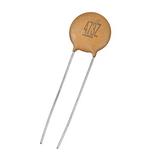
A ceramic capacitor is a fixed-value capacitor where the ceramic material acts as the dielectric. It is constructed of two or more alternating layers of ceramic and a metal layer acting as the electrodes. The composition of the ceramic material defines the electrical behavior and therefore applications. Ceramic capacitors are divided into two application classes:
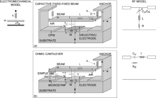
A radio-frequency microelectromechanical system is a microelectromechanical system with electronic components comprising moving sub-millimeter-sized parts that provide radio-frequency (RF) functionality. RF functionality can be implemented using a variety of RF technologies. Besides RF MEMS technology, III-V compound semiconductor, ferrite, ferroelectric, silicon-based semiconductor, and vacuum tube technology are available to the RF designer. Each of the RF technologies offers a distinct trade-off between cost, frequency, gain, large-scale integration, lifetime, linearity, noise figure, packaging, power handling, power consumption, reliability, ruggedness, size, supply voltage, switching time and weight.
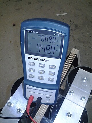
An LCR meter is a type of electronic test equipment used to measure the inductance (L), capacitance (C), and resistance (R) of an electronic component. In the simpler versions of this instrument the impedance was measured internally and converted for display to the corresponding capacitance or inductance value. Readings should be reasonably accurate if the capacitor or inductor device under test does not have a significant resistive component of impedance. More advanced designs measure true inductance or capacitance, as well as the equivalent series resistance of capacitors and the Q factor of inductive components.
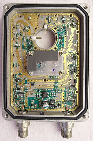
A distributed-element filter is an electronic filter in which capacitance, inductance, and resistance are not localised in discrete capacitors, inductors, and resistors as they are in conventional filters. Its purpose is to allow a range of signal frequencies to pass, but to block others. Conventional filters are constructed from inductors and capacitors, and the circuits so built are described by the lumped element model, which considers each element to be "lumped together" at one place. That model is conceptually simple, but it becomes increasingly unreliable as the frequency of the signal increases, or equivalently as the wavelength decreases. The distributed-element model applies at all frequencies, and is used in transmission-line theory; many distributed-element components are made of short lengths of transmission line. In the distributed view of circuits, the elements are distributed along the length of conductors and are inextricably mixed together. The filter design is usually concerned only with inductance and capacitance, but because of this mixing of elements they cannot be treated as separate "lumped" capacitors and inductors. There is no precise frequency above which distributed element filters must be used but they are especially associated with the microwave band.

A waveguide filter is an electronic filter constructed with waveguide technology. Waveguides are hollow metal conduits inside which an electromagnetic wave may be transmitted. Filters are devices used to allow signals at some frequencies to pass, while others are rejected. Filters are a basic component of electronic engineering designs and have numerous applications. These include selection of signals and limitation of noise. Waveguide filters are most useful in the microwave band of frequencies, where they are a convenient size and have low loss. Examples of microwave filter use are found in satellite communications, telephone networks, and television broadcasting.


