JP2018117922A - Portable device case, portable device, and watch - Google Patents
Portable device case, portable device, and watch Download PDFInfo
- Publication number
- JP2018117922A JP2018117922A JP2017012249A JP2017012249A JP2018117922A JP 2018117922 A JP2018117922 A JP 2018117922A JP 2017012249 A JP2017012249 A JP 2017012249A JP 2017012249 A JP2017012249 A JP 2017012249A JP 2018117922 A JP2018117922 A JP 2018117922A
- Authority
- JP
- Japan
- Prior art keywords
- band
- case
- portable device
- timepiece
- watch
- Prior art date
- Legal status (The legal status is an assumption and is not a legal conclusion. Google has not performed a legal analysis and makes no representation as to the accuracy of the status listed.)
- Pending
Links
Images
Classifications
-
- G—PHYSICS
- G04—HOROLOGY
- G04B—MECHANICALLY-DRIVEN CLOCKS OR WATCHES; MECHANICAL PARTS OF CLOCKS OR WATCHES IN GENERAL; TIME PIECES USING THE POSITION OF THE SUN, MOON OR STARS
- G04B37/00—Cases
- G04B37/14—Suspending devices, supports or stands for time-pieces insofar as they form part of the case
- G04B37/1486—Arrangements for fixing to a bracelet
-
- G—PHYSICS
- G04—HOROLOGY
- G04B—MECHANICALLY-DRIVEN CLOCKS OR WATCHES; MECHANICAL PARTS OF CLOCKS OR WATCHES IN GENERAL; TIME PIECES USING THE POSITION OF THE SUN, MOON OR STARS
- G04B37/00—Cases
- G04B37/18—Cases for pocket or wrist watches
-
- A—HUMAN NECESSITIES
- A44—HABERDASHERY; JEWELLERY
- A44C—PERSONAL ADORNMENTS, e.g. JEWELLERY; COINS
- A44C5/00—Bracelets; Wrist-watch straps; Fastenings for bracelets or wrist-watch straps
- A44C5/14—Bracelets; Wrist-watch straps; Fastenings for bracelets or wrist-watch straps characterised by the way of fastening to a wrist-watch or the like
- A44C5/16—Bracelets; Wrist-watch straps; Fastenings for bracelets or wrist-watch straps characterised by the way of fastening to a wrist-watch or the like by folding the strap
-
- A—HUMAN NECESSITIES
- A44—HABERDASHERY; JEWELLERY
- A44C—PERSONAL ADORNMENTS, e.g. JEWELLERY; COINS
- A44C5/00—Bracelets; Wrist-watch straps; Fastenings for bracelets or wrist-watch straps
- A44C5/18—Fasteners for straps, chains or the like
- A44C5/20—Fasteners for straps, chains or the like for open straps, chains or the like
- A44C5/2071—Fasteners for straps, chains or the like for open straps, chains or the like with the two ends of the strap or chain overlapping each other and fastened by an action perpendicularly to the main plane of these two ends
Landscapes
- Physics & Mathematics (AREA)
- General Physics & Mathematics (AREA)
- Electric Clocks (AREA)
- Purses, Travelling Bags, Baskets, Or Suitcases (AREA)
Abstract
Description
本発明は、携帯機器用ケース、携帯機器及び時計に関する。 The present invention relates to a portable device case, a portable device, and a watch.
従来、携帯機器用ケースとしては、例えば特許文献1に開示されている携帯機器用ケースがある。前記携帯機器用ケースは、腕に装着される。前記携帯機器用ケースは、ケース本体と、ケース本体の両側に固定されている2つのバンドとを備える。一方のバンドの先端には美錠が設けられている。美錠は、つく棒を有している。一方のバンドには環状の遊嵌部材が通されている。他方のバンドの先端側には、係止孔が設けられている。 Conventionally, as a portable device case, for example, there is a portable device case disclosed in Patent Document 1. The portable device case is attached to an arm. The portable device case includes a case main body and two bands fixed to both sides of the case main body. A beautiful tablet is provided at the tip of one band. A beautiful tablet has a stick. An annular loosely fitting member is passed through one band. A locking hole is provided on the tip side of the other band.
前記携帯機器用ケースを腕に装着する際には、以下の4つの操作を行う。
(1)腕にケース本体を載せて一方のバンドの美錠に他方のバンドを通す。
(2)他方のバンドを引っ張って両方のバンドを腕に締め付ける。
(3)他方のバンドの係止孔につく棒を通す。
(4)他方のバンドを遊嵌部材に通して嵌めて一方のバンドに固定する。
When the portable device case is worn on the arm, the following four operations are performed.
(1) Place the case body on the arm and pass the other band through the beautiful lock of one band.
(2) Pull the other band and tighten both bands on the arm.
(3) Pass the rod attached to the locking hole of the other band.
(4) The other band is fitted through the loosely fitting member and fixed to the one band.
しかしながら、前記携帯機器用ケースでは、装着の際に4つの操作を行わなければならず、装着に手間がかかる。 However, in the case for the portable device, four operations must be performed at the time of mounting, which takes time and effort.
本発明は、このような従来の課題に鑑みてなされたものであり、装着を容易に行うことができる携帯機器用ケース、携帯機器及び時計を提供することを目的とする。 The present invention has been made in view of such conventional problems, and an object of the present invention is to provide a portable device case, a portable device, and a timepiece that can be easily attached.
本発明の一態様は、ケース本体と、通過口を有し、前記ケース本体に設けられたバンド取付部と、前記バンド取付部に一端部が取り付けられ、他端部が前記通過口に挿通されたバンドと、前記バンドのうち前記通過口より外に延出する延出部に設けられ、前記バンド取付部から前記通過口に至る主部に着脱可能に連結される固定部材と、を備える携帯機器用ケースを提供する。 One aspect of the present invention includes a case main body, a passage opening, a band attaching portion provided in the case main body, one end attached to the band attaching portion, and the other end inserted through the passage opening. And a fixing member that is provided in an extending part that extends out of the passing port and is detachably connected to a main part that extends from the band mounting part to the passing port. Provide equipment case.
前記携帯機器用ケースによれば、腕等への装着にあたって、2つの操作(バンドの締付操作、およびバンドの固定操作)を行えばよいため、従来よりも装着に必要な操作が少なくなる。よって、前記携帯機器用ケースの装着を容易に行うことができる。 According to the portable device case, two operations (a band tightening operation and a band fixing operation) may be performed for mounting on the arm or the like, and therefore, fewer operations are required than conventional. Therefore, the portable device case can be easily attached.
前記携帯機器用ケースは、前記バンド取付部が、前記ケース本体の一端部に設けられ、前記ケース本体の他端部には、前記主部を支持する支持部が設けられている構成とすることができる。
この構成によれば、バンドがケース本体の両端部に支持される。そのため、前記携帯機器用ケースは、ケース本体を安定的に保持することができる。
The portable device case has a configuration in which the band attaching portion is provided at one end portion of the case main body, and a support portion for supporting the main portion is provided at the other end portion of the case main body. Can do.
According to this structure, a band is supported by the both ends of a case main body. Therefore, the case for the portable device can stably hold the case main body.
前記固定部材は、前記主部に形成された被係止部に係脱可能に係止する係止部である構成とすることができる。
この構成によれば、係止部を被係止部に係止させるだけで延出部を前記主部に固定できるため、バンドの固定操作が容易になる。よって、前記携帯機器用ケースは、装着をさらに容易に行うことができる。
The fixing member may be a locking portion that is detachably locked to a locked portion formed in the main portion.
According to this configuration, since the extending portion can be fixed to the main portion simply by locking the locking portion to the locked portion, the band fixing operation is facilitated. Therefore, the portable device case can be mounted more easily.
前記携帯機器用ケースは、前記バンド及び前記バンドが接触する被接触部の少なくとも一方に設けられ、前記バンドと前記被接触部との摩擦を低減する滑り部を備える構成とすることができる。
この構成によれば、バンドの締め付け時における摩擦を低減してバンドをスムーズに移動させるため、バンドの締め付け操作が容易になる。よって、携帯機器用ケースの装着を容易に行うことができる。
The portable device case may include a sliding portion that is provided in at least one of the band and the contacted portion that contacts the band and reduces friction between the band and the contacted portion.
According to this configuration, since the band is smoothly moved by reducing friction at the time of tightening the band, the band tightening operation is facilitated. Therefore, it is possible to easily attach the portable device case.
前記滑り部は、少なくとも先端部が湾曲凸状に形成された突起であってよい。
この構成によれば、バンドの締め付け時における摩擦をさらに低減し、バンドの締め付け操作を容易にできる。
The sliding portion may be a protrusion having at least a tip portion formed in a curved convex shape.
According to this configuration, it is possible to further reduce the friction at the time of tightening the band and facilitate the band tightening operation.
前記滑り部は、前記バンド及び前記被接触部の少なくとも一方に設けられ、前記バンドの長さ方向と交差する軸の周りに回転可能な回転部材である構成とすることができる。
この構成によれば、バンドの締め付けの際に摩擦を低減できるため、バンドを容易に締め付けることが可能になる。
The said sliding part can be set as the structure which is provided in at least one of the said band and the said to-be-contacted part, and is a rotating member rotatable around the axis | shaft which cross | intersects the length direction of the said band.
According to this configuration, since the friction can be reduced when the band is tightened, the band can be easily tightened.
本発明の一態様は、前記携帯機器用ケースと、前記携帯機器用ケースに収納される携帯機器用の部品と、を備える携帯機器を提供する。
前記携帯機器は、腕への装着にあたって、2つの操作(バンドの締付操作、およびバンドの固定操作)を行えばよいため、従来よりも装着に必要な操作が少なくなる。よって、装着を容易に行うことができる。
One embodiment of the present invention provides a mobile device including the mobile device case and parts for a mobile device housed in the mobile device case.
Since the portable device needs only two operations (band tightening operation and band fixing operation) to be mounted on the arm, the number of operations required for mounting is less than in the prior art. Therefore, attachment can be performed easily.
本発明の一態様は、前記携帯機器用ケースと、前記携帯機器用ケースに収納されるムーブメントと、を備える時計を提供する。
前記時計は、腕への装着にあたって、2つの操作(バンドの締付操作、およびバンドの固定操作)を行えばよいため、従来よりも装着に必要な操作が少なくなる。よって、装着を容易に行うことができる。
One embodiment of the present invention provides a timepiece including the portable device case and a movement housed in the portable device case.
Since the watch needs only to perform two operations (a band tightening operation and a band fixing operation) when mounting the wristwatch on the wrist, fewer operations are required than in the past. Therefore, attachment can be performed easily.
本発明の携帯機器用ケース、携帯機器及び時計は、装着を容易に行うことができる。 The portable device case, portable device, and watch of the present invention can be easily attached.
次に、本発明の実施形態を図面に基づいて説明する。
(第1の実施形態)
図1から図6を参照し、本発明の第1の実施形態の時計1(携帯機器)について説明する。図1は、第1の実施形態の時計1の斜視図である。
図1に示すように、時計1は、腕時計型の電子時計である。時計1は、腕(手首)に装着される。時計1は、時計用ケース3(携帯機器用ケース)と、時計用のムーブメント(携帯機器用の部品、以下、時計用の部品と称する場合もある。)とを備える。
Next, embodiments of the present invention will be described with reference to the drawings.
(First embodiment)
A timepiece 1 (portable device) according to a first embodiment of the present invention will be described with reference to FIGS. 1 to 6. FIG. 1 is a perspective view of a timepiece 1 according to the first embodiment.
As shown in FIG. 1, the timepiece 1 is a wristwatch-type electronic timepiece. The watch 1 is worn on the arm (wrist). The timepiece 1 includes a timepiece case 3 (case for a portable device) and a movement for a timepiece (parts for a portable device, hereinafter sometimes referred to as parts for a timepiece).
時計用ケース3は、ケース本体5と、第1かん7(バンド取付部)と、第2かん9(支持部)と、バンド11と、固定部材13とを備える。
The
ケース本体5は、ケース状に形成されている。「ケース状」は、収納物を収納できる等の構造をいう。
ケース本体5には、上記の時計用の部品(ムーブメント)が設けられている。具体的には、ケース本体5の表面(上面20)には表示部15が設けられている。表示部15は、平板状をなした液晶表示パネル等からなり、時刻等の情報を表示する。ケース本体5内には、ムーブメント等が収容されている。ムーブメントは、駆動ユニット及びバッテリ等を備え、表示部15における情報の表示を制御する。
The
The
以下、必要に応じてXYZ座標系を用いて説明を行う。
平板状のケース本体5の一方の面は、第1かん7及び第2かん9が設けられる下面19(図2参照)である。ケース本体5の他方の面は、表示部15が設けられる上面20である。
X方向は、ケース本体5の一方の面(下面19)に沿う方向であり、ケース本体5の一端部5aと他端部5bとを通る方向である。X方向のうち、他端部5bから一端部5aに向かう方向を+X方向といい、その反対方向を−X方向という。Y方向は、ケース本体5の一方の面(下面19)に沿う面内にあってX方向に直交する方向である。Y方向のうち一方の方向を+Y方向といい、その反対方向を−Y方向という。Z方向はX方向及びY方向に直交する方向であり、ケース本体5の厚さ方向である。Z方向のうち、下面19から上面20に向かう方向を上方といい、その反対方向を下方ということがある。
X方向とY方向とによって形成される平面をXY平面という。Y方向とZ方向とによって形成される平面をYZ平面という。X方向とZ方向とによって形成される平面をXZ平面という。
Hereinafter, description will be made using an XYZ coordinate system as necessary.
One surface of the
The X direction is a direction along one surface (lower surface 19) of the
A plane formed by the X direction and the Y direction is referred to as an XY plane. A plane formed by the Y direction and the Z direction is referred to as a YZ plane. A plane formed by the X direction and the Z direction is referred to as an XZ plane.
第1かん7は、ケース本体5の一端部5aに設けられている。第1かん7は、一対の第1かん足21,21と、ばね棒23とを備える。
第1かん足21,21は、ケース本体5の一端部5aにY方向に離間して設けられている。第1かん足21,21は、例えば、ケース本体5に一体形成されている。第1かん足21,21は、ケース本体5の一端部5aから、概略、下方に延びて形成されている。第1かん足21,21は、詳しくは、ケース本体5の一端部5aの下面19から、わずかに+X方向に傾斜して下方に延出している。
The
The
ばね棒23は、第1かん足21,21間に設けられている。ばね棒23の両端は、第1かん足21,21の下部(延出方向の先端部)に回転可能に取り付けられている。
ばね棒23とケース本体5の一端部5aとの間は、第1通過口25(通過口、通過部)とされている。第1通過口25は、バンド11が挿通可能である。
The
A space between the
図2は、時計1の側面図である。第2かん9は、ケース本体5の他端部5bに設けられている。第2かん9は、例えば、ケース本体5に一体形成されている。第2かん9は、第2かん足31,31と、連結部33とを備える。
第2かん足31,31は、ケース本体5の他端部5bにY方向に離間して設けられている。第2かん足31,31は、ケース本体5の他端部5bから、概略、下方に延びて形成されている。第2かん足31,31は、詳しくは、ケース本体5の他端部5bの下面19から、やや−X方向に傾斜して下方に延出している。
FIG. 2 is a side view of the timepiece 1. The
The
連結部33は、第2かん足31,31間に設けられている。連結部33の両端は、第2かん足31,31の下部(延出方向の先端部)に達している。連結部33とケース本体5の他端部5bとの間は、第2通過口35とされている。第2通過口35は、バンド11が挿通可能である。
The connecting
バンド11は、例えば、革製、樹脂製等のバンドである。バンド11は、厚さ方向に弾性的に曲げ変形可能である。バンド11は、例えば、係止穴61の内径寸法が増減されるような弾性変形が可能である。
The
バンド11は、一端部11aが第1かん7に取り付けられている。バンド11の他端部11bは第1通過口25に挿通されている。すなわち、バンド11の他端部11bを含む長さ部分は第1通過口25に挿通されている。
バンド11は、一端部11aから他端部11bにかけて、主部41と、延出部43(余長部)とを有する。
主部41の一端部(バンド11の一端部11a)は、ばね棒23に回動自在に取り付けられている。詳しくは、一端部11aは挿通孔を有する筒状に形成され、前記挿通孔にばね棒23が挿通している。一端部11aは、ばね棒23に対して軸回りに回動可能である。
主部41は、バンド11のうち、第1かん7から第1通過口25に至る部分である。主部41は、第1かん7から第2かん9を経て第1通過口25に至る輪状に形成されている。主部41は、第2かん9の外側(−X方向側)から内側(+X方向側)に向けて第2通過口35に挿通し、ケース本体5の下面19に沿って+X方向に延びて第1通過口25に達している。主部41は、第2通過口35に挿通しているため、第2かん9の連結部33に支持される。主部41の形態は、「ループ状」または「環状」ともいえる。
One
The
One end of the main portion 41 (one
The
延出部43は、バンド11のうち、第1通過口25からバンド11の他端部11bにかけて、主部41の外に延出している部分である。延出部43は、例えば、主部41の表面45に重ねられている。
The extending
主部41及び延出部43には、バンド11を厚さ方向に貫通する複数の係止穴61が形成されている。係止穴61は、例えば、バンド11の厚さ方向に見て円形状とされている。複数の係止穴61は、例えば、バンド11の長さ方向の異なる位置に形成されている。複数の係止穴61は、バンド11の幅方向の中間部分に、バンド11の長さ方向に並んで形成されている。バンド11に形成された係止穴61のうち、主部41に形成された複数の係止穴61は「被係止部」の一例である。
The
図3は、固定部材13を示す斜視図である。
図3に示すように、固定部材13は、係止部51を備える。係止部51は、頭部52と、軸部53とを有する。頭部52は、例えば円板状に形成されている。
軸部53は、例えば、頭部52の一方の面の中央から頭部52に対して垂直に突出して形成されている。軸部53は、例えば、軸方向が突出方向に一致する円柱状に形成され、軸部53の外形寸法(外径)は、頭部52の外形寸法(外径)より小さい。軸部53の外形寸法(外径)は、例えば係止穴61の内径より小さい。そのため、軸部53は、係止穴61に挿通可能となる。
FIG. 3 is a perspective view showing the fixing
As shown in FIG. 3, the fixing
The
軸部53の外周面には、第1環状凸部54と、第2環状凸部55とが形成されている。第1環状凸部54は、例えば円環状の凸部である。第1環状凸部54は、軸部53の長さ方向の中間部に形成されている。第2環状凸部55は、軸部53の長さ方向の先端部に形成されている。第2環状凸部55は、例えば円環状の凸部である。
第1環状凸部54及び第2環状凸部55は、軸部53の外周面から軸部53の径方向外方に突出して、軸部53の全周にわたって形成されている。第1環状凸部54及び第2環状凸部55の中心軸は、例えば軸部53の中心軸に一致する。第1環状凸部54及び第2環状凸部55の断面形状(軸部53の中心軸に沿う断面の形状)は特に限定されず、例えば半円形、矩形、逆V字形などとしてよい。
A first annular
The first annular
第1環状凸部54の少なくとも一部は、例えば、外形寸法(外径)が、バンド11(主部41および延出部43)の係止穴61の内径より大きい。第1環状凸部54の外形寸法(外径)は、係止穴61を押し広げれば係止穴61を通過可能な程度とされる。そのため、係止穴61を押し広げれば係止穴61を通過でき、かつ係止穴61の周縁部に係脱可能に係止できる。
第2環状凸部55の少なくとも一部は、例えば、外形寸法(外径)が、バンド11(主部41)の係止穴61の内径より大きい。第2環状凸部55の外形寸法(外径)は、係止穴61を押し広げれば係止穴61を通過可能な程度とされる。そのため、係止穴61を押し広げれば係止穴61を通過でき、かつ係止穴61の周縁部に係脱可能に係止できる。
At least a part of the first
At least a part of the second
頭部52と第1環状凸部54との離間距離は、例えば、バンド11(延出部43)の厚さと同じ、またはこれよりやや大きい。第1環状凸部54と第2環状凸部55との離間距離は、例えば、バンド11(主部41)の厚さと同じ、またはこれよりやや大きい。
係止部51は、複数の係止穴61のいずれにも装着できる。
The separation distance between the
The locking
図2に示すように、係止部51の軸部53は、延出部43の表面45側から延出部43および主部41の係止穴61に挿入されている。頭部52は延出部43の表面45に配置される。
軸部53が主部41および延出部43の係止穴61に挿通することによって、延出部43は、主部41に対する長さ方向の移動が規制される。
軸部53が、バンド11の他端部11bにおいて延出部43の係止穴61に挿通することによって、延出部43の先端部(他端部11bを含む部分)は、主部41に固定される。
As shown in FIG. 2, the
When the
The
第1環状凸部54は、主部41と延出部43の間にあり、主部41の係止穴61の表面45側の周縁部、および延出部43の係止穴61の裏面47側の周縁部に係脱可能に係止する。第2環状凸部55は、主部41の裏面47側にあり、主部41の係止穴61の裏面47側の周縁部に係脱可能に係止する。
これによって、主部41および延出部43は、係止部51に対して位置決めされる。そのため、延出部43は、主部41に着脱可能に連結され、固定される。
The first annular
As a result, the
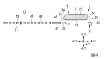
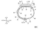
図4〜図6は、時計1の装着方法を示す図である。図4〜図6を用いて時計1の装着方法を説明する。
[1]主部41の形成
図4に示すように、バンド11が伸ばされた状態から、図5に示すように、バンド11の先端部を第2通過口35、第1通過口25の順に通して輪状の主部41を形成する。主部41は、腕Aを通した状態とする。係止部51は、例えば、延出部43の先端部(他端部11bを含む部分)の係止穴61に装着しておいてもよいし、固定操作(後述)の際に係止穴61に装着してもよい。
4 to 6 are diagrams showing a method of attaching the timepiece 1. A method for attaching the timepiece 1 will be described with reference to FIGS.
[1] Formation of
[2]バンド11の締付操作
図5に示すように、主部41内に腕Aを通した状態で延出部43を引っ張り、バンド11(主部41)を腕Aに締め付ける。
[2] Tightening operation of the
[3]バンド11の固定操作
図6に示すように、延出部43を主部41に重ねて、主部41の係止穴61に係止部51を挿入して係止させ、延出部43を主部41に固定する。これによりバンド11が腕Aに固定され、時計1が腕Aに装着される。
[3] Fixing operation of the
時計用ケース3の作用効果を説明する。
(1)時計用ケース3は、腕Aへの装着にあたって、主部41内に腕Aを通した状態から片手で2つの操作(バンド11の締付操作、およびバンド11の固定操作)を行えばよいため、従来の時計用ケースよりも装着に必要な操作が少なくなる。よって、時計用ケース3は、装着を容易に行うことができる。
(2)時計用ケース3では、ケース本体5の他端部5bに、主部41を支持する第2かん9が設けられている。これにより、バンド11がケース本体5の両端部(一端部5aおよび他端部5b)に支持される。よって、時計用ケース3は、装着時にケース本体5を安定的に保持することができる。
(3)時計用ケース3は、係止部51を係止穴61に係止させるだけで延出部43を主部41に固定できるため、バンド11の固定操作が容易になる。よって、時計用ケース3は、装着をさらに容易に行うことができる。
(4)時計用ケース3では、係止部51が主部41の複数の係止穴61のいずれにも着脱可能に係止できるため、バンド11の固定位置を任意に定めることができる。そのため、例えば、外力が作用しにくい位置に係止部51を設けることができる。よって、時計用ケース3は、使い勝手の点で優れている。
(5)時計用ケース3では、第2かん9がケース本体5に一体形成されているため、第2かん9がケース本体5と別体に形成されている場合に比べて部品点数が少なくなり、部品コストが抑えられる。よって、時計用ケース3は、製造コストを抑えることができる。
(6)時計用ケース3では、バンド11を折り返さずに用いるため、着脱時にバンド11にかかる負荷を抑制することができる。よって、時計用ケース3は、バンド11の表面の亀裂などの破損を防ぐことができ、耐久性の点で優れている。
(7)時計用ケース3では、バンド11を折り返さずに用いるため、バンド11の折り返しによる隙間は生じない。そのため、ケース本体5の端でバンド11の厚さ方向の寸法が大きくなるのが抑制される。よって、時計用ケース3は、装着感が高く、かつ外観(美観)の点で優れている。
(8)時計用ケース3では、第1かん7および第2かん9がケース本体5に一体形成されているため、ケース本体5の製造が容易であり、製造コストを抑制できる。
(9)時計1は、時計用ケース3を備えるため、腕Aへの装着にあたって、片手で2つの操作(バンド11の締付操作、およびバンド11の固定操作)を行えばよく、従来の時計よりも装着に必要な操作が少なくなる。よって、時計1は、装着を容易に行うことができる。
なお、上記実施形態においては、時計用ケース3は第1かん7および第2かん9を備えているが、時計用ケースの構成はこれに限定されない。実施形態の時計用ケースは、第1かんの第1通過口にバンドの他端部を含む部分が挿通され、バンドに固定される構成であればよく、後述のように、例えば、第2かんを備えていない構成も可能である。
The effect of the
(1) When the
(2) In the
(3) Since the
(4) In the
(5) In the
(6) Since the
(7) In the
(8) In the
(9) Since the timepiece 1 includes the
In the above embodiment, the
(第2の実施形態)
図7および図8を用いて本発明の第2の実施形態について説明する。なお、先に説明した実施形態と共通の構成については同じ符号を付して説明を省略する。
図7は、第2の実施形態の時計用ケースのバンド401を裏側から視た斜視図である。図7に示すように、バンド401の裏面47には、一対の突起403,403(滑り部)が設けられている。一対の突起403,403は、バンド401の長さ方向に延びて設けられている。一対の突起403,403は、バンド401の幅方向に間隔をおいて設けられている。
(Second Embodiment)
A second embodiment of the present invention will be described with reference to FIGS. In addition, the same code | symbol is attached | subjected about the same structure as embodiment described previously, and description is abbreviate | omitted.
FIG. 7 is a perspective view of the
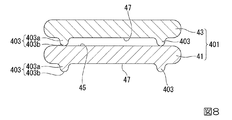
図8は、バンド401の締め付け時に主部41と延出部43とが重なる状態を示す断面図である。図8は、突起403の延在方向に直交する方向の断面を示す。
図8に示すように、突起403は、バンド401の裏面47から突出して形成されている。突起403の突出方向は、例えば、裏面47に対して垂直な方向(図8において下方)である。
突起403は、先端に向かって徐々に幅が狭くなる基台部403aと、基台部403aの先端側に設けられた湾曲凸状の先端部403bとを有する。先端部403bの断面形状は、例えば半円状である。突起403は、バンド401と一体に形成することができる。
FIG. 8 is a cross-sectional view showing a state where the
As shown in FIG. 8, the
The
バンド401の締め付け時には、主部41の表面45(被接触部)に延出部43が重なる。延出部43は、裏面47に設けられた突起403,403の先端部403bにおいて主部41の表面45に接触する。そのため、主部41に対する延出部43の接触面積が小さくなる。これにより、突起403,403は、主部41の表面45との間の摩擦を低減することができる。
When the
延出部43が接触する被接触部としては、図8で示した主部41の表面45に加えて、第1かん7のばね棒23(図4参照)、第2かん9の連結部33(図4参照)等を例示できる。
As the contacted portion with which the extending
第2の実施形態の時計用ケースの作用効果について説明する。
(1)第2の実施形態の時計用ケースでは、バンド401に突起403,403(滑り部)が形成されている。これにより、時計用ケースは、バンド401の締め付け時におけるバンド401の摩擦を低減してバンド401をスムーズに移動させるため、バンド401の締め付操作が容易になる。よって、第2の実施形態の時計用ケースは、装着を容易に行うことができる。
(2)突起403は、バンド401と一体に形成できるため、時計用ケースの製造コストを抑えることが可能になる。
(3)突起403の先端部403bが湾曲凸状に形成されているため、バンド11の締め付け時における摩擦をさらに低減し、バンド11の締め付け操作を容易にできる。
The effect of the timepiece case of the second embodiment will be described.
(1) In the watch case of the second embodiment,
(2) Since the
(3) Since the
第2の実施形態の時計用ケースでは、突起403は、バンド401の長さ方向に延びるように設けたが、滑り部の構成は図示例に限定されない。例えば、滑り部は、複数の突起をバンド401の長さ方向に断続的に設けた構成であってもよい。
第2の実施形態の時計用ケースでは、突起403は、裏面47にのみ設けられているが、突起403は、バンド401の表面45にのみ設けてもよいし、表面45及び裏面47の両方に設けてもよい。
また、ケース本体5においてバンド401が接触する被接触部に突起を設けてもよい。具体的には、ケース本体5の下面19(図2参照)、第1かん7のばね棒23(図4参照)、第2かん9の連結部33(図4参照)に突起を設けてもよい。
In the watch case of the second embodiment, the
In the watch case of the second embodiment, the
Further, the
(第3の実施形態)
図9を用いて本発明の第3の実施形態の時計501について説明する。なお、先に説明した実施形態と共通の構成については同じ符号を付して説明を省略する。
図9は、第3の実施形態の時計501を裏側から視た斜視図である。時計501は、時計用ケース503と、ムーブメントとを備える。時計用ケース503は、ケース本体5と、第1かん7と、第2かん9と、バンド11と、固定部材13とを備える。
(Third embodiment)
A
FIG. 9 is a perspective view of a
時計用ケース503では、回転部材505,505は、例えば挿通孔を有する円筒状の部材であり、前記挿通孔にはばね棒23が挿通している。回転部材505,505は、ばね棒23の長さ方向(Y方向)の両端部にそれぞれ配置されている。
回転部材505の外径は、バンド11の一端部11aの外径よりも大きい。上述のように、一端部11aはばね棒23の軸回りに回動可能であるため、回転部材505は、一端部11aに対してばね棒23の軸回りに相対的に回動可能である。回転部材505は、ばね棒23に対して軸回りに回転可能であってもよいし、ばね棒23に固定されていてもよい。回転部材505,505の合計長さ(Y方向の寸法)は、バンド11の一端部11aの全幅(Y方向の寸法)よりも短い。
バンド11(他端部11bを含む部分)は、締め付けのために第1通過口25に挿入されて長さ方向に移動する際に、回転部材505,505に当接するが、外径が小さいバンド11の一端部11aには当接しにくい。そのため、バンド11と他の部材との接触面積を小さく抑えることができる。よって、バンド11の締め付けの際の摩擦を低減できる。
回転部材505がばね棒23に対して回転可能である場合には、バンド11の締め付けの際に、バンド11の移動に従って回転部材505も回転する。よって、バンド11の締め付けの際の摩擦をさらに低減できる。
In the
The outer diameter of the rotating
The band 11 (the part including the
When the rotating
時計用ケース503の作用効果を説明する。
(1)時計用ケース503は、回転部材505を備えているため、バンド11の締め付けの際に摩擦を低減できる。そのため、バンド11を容易に締め付けることが可能になる。よって、時計用ケース503は、装着を容易に行うことができる。
(2)時計用ケース503では、回転部材505が回転可能に構成されている場合には、回転部材505の回転を利用してバンド11の摩擦を低減できる。よって、バンド11を容易に締め付けることが可能になる。
The effect of the
(1) Since the
(2) In the
時計用ケース503では、ばね棒23(被接触部)に回転部材505,505を設けたが、滑り部の構成は、バンド11と被接触部との摩擦を低減できる構成であればよく、図示例に限定されない。例えば、時計用ケース503では、回転部材505を2つ使用したが、回転部材の数は特に限定されず、1以上の任意の数でもよい。回転部材は、円筒状に限らず、球状であってもよい。また、滑り部は、バンド11との摩擦を低減できる構造であれば回転可能でなくてもよい。回転部材は、バンドに、例えばばね棒周りに回転可能となるように取り付けられていてもよい。
In the
第2の実施形態と第3の実施形態の時計用ケースでは、滑り部として突起403、回転部材505をそれぞれ使用したが、突起403及び回転部材505の両方を使用してもよい。また滑り部としては、突起や回転部材の他に、例えば滑り性が高いシートでもよい。
In the watch case of the second embodiment and the third embodiment, the
以上、図面を参照して、本発明の実施形態を詳述してきたが、具体的な構成はこの実施の形態に限らず、本発明の要旨を逸脱しない程度の設計的変更は、本発明に含まれる。
例えば、図10に示す時計用ケース603のように、第1かん607及び第2かん609をケース本体5にそれぞれ回動軸611、613により回動可能に設けてもよい。また第1かん607及び第2かん609の一方をケース本体5に回動可能に設けてもよい。この構造によれば、時計用ケース603の装着性を高めることができる。図10において、601は、時計用ケース603を用いた時計である。
Although the embodiment of the present invention has been described in detail with reference to the drawings, the specific configuration is not limited to this embodiment, and design changes that do not depart from the gist of the present invention are not limited to the present invention. included.
For example, a
延出部を主部に固定する固定部材は、遊革とマグネットの少なくとも一方であってもよい。マグネットは、永久磁石等であり、磁力によって延出部を主部に固定する。例えば、延出部と主部の一方にマグネットを設け、他方の少なくとも一部が磁性金属からなる構成を例示できる。また、固定部材は、複数用いてもよい。
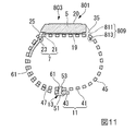
図1および図2に示す実施形態の時計用ケース(および時計)では、第2かん9は第2かん足31,31と連結部33とから構成されているが、実施形態の時計用ケース(および時計)は、図11に示す構成でもよい。図11に示す時計用ケース803(および時計801)では、第2かん809は第2かん足811,811とばね棒813とから構成されている。時計用ケース803では、ケース本体5の材料にかかわらず、強度の高い固定構造が得られる。なお、図11では、固定部材の図示を省略している。
The fixing member that fixes the extension part to the main part may be at least one of a free leather and a magnet. The magnet is a permanent magnet or the like, and fixes the extending part to the main part by magnetic force. For example, a configuration in which a magnet is provided on one of the extension part and the main part and at least a part of the other part is made of a magnetic metal can be exemplified. A plurality of fixing members may be used.
In the timepiece case (and timepiece) of the embodiment shown in FIGS. 1 and 2, the
図1および図2に示す実施形態の時計用ケース3(および時計1)は第1かん7および第2かん9を備えているが、実施形態の時計用ケース(および時計)は、図12に示す構成でもよい。図12に示す時計用ケース903(および時計901)は、第2かんがない点で図1および図2に示す時計用ケース3(および時計1)と異なる。
The timepiece case 3 (and the timepiece 1) of the embodiment shown in FIGS. 1 and 2 includes the first and
実施形態では、時計用ケースに本発明を適用した例を説明したが、バンドを備える携帯機器用ケースであれば本発明を適用することができる。実施形態では、腕に装着する携帯機器用ケースに本発明を適用した例を説明したが、装着対象は腕に限定されない。例えば身体の腕以外の部位に装着する携帯機器用ケースに本発明を適用してもよい。
携帯機器用の部品は、時計用のムーブメントに限らず、例えば、活動量計、心拍計、歩数計、高度計、気圧計等の部品であってもよい。
In the embodiment, an example in which the present invention is applied to a watch case has been described. However, the present invention can be applied to a case for a portable device having a band. In the embodiment, the example in which the present invention is applied to the case for the mobile device to be worn on the arm has been described, but the wearing target is not limited to the arm. For example, you may apply this invention to the case for portable devices with which it mounts | wears on site | parts other than a body arm.
The parts for the portable device are not limited to the movement for the watch, but may be parts such as an activity meter, a heart rate monitor, a pedometer, an altimeter, and a barometer.
1,501,601,801,901・・・時計(携帯機器)、3,503,603,803,903・・・時計用ケース(携帯機器用ケース)、5・・・ケース本体、5a・・・ケース本体の一端部、5b・・・ケース本体の他端部、7,607・・・第1かん(バンド取付部)、9,609,809・・・第2かん(支持部)、11,401・・・バンド、11a・・・バンドの一端部、11b・・・バンドの他端部、13・・・固定部材、23・・・ばね棒(被接触部)、25・・・第1通過口(通過口)、41・・・主部、43・・・延出部、51・・・係止部、61・・・係止穴(被係止部)、403・・・突起(滑り部)、403b・・・先端部、505・・・回転部材(滑り部) 1,501,601,801,901 ... watch (mobile device), 3,503,603,803,903 ... watch case (mobile device case), 5 ... case body, 5a One end of the case main body, 5b... The other end of the case main body, 7,607... The first can (band mounting portion), 9, 609, 809. , 401 ... band, 11a ... one end of the band, 11b ... other end of the band, 13 ... fixing member, 23 ... spring bar (contacted part), 25 ... first 1 passing port (passing port), 41 ... main part, 43 ... extending part, 51 ... locking part, 61 ... locking hole (locked part), 403 ... projection (Sliding part), 403b ... tip part, 505 ... rotating member (sliding part)
Claims (8)
通過口を有し、前記ケース本体に設けられたバンド取付部と、
前記バンド取付部に一端部が取り付けられ、他端部が前記通過口に挿通されたバンドと、
前記バンドのうち前記通過口より外に延出する延出部に設けられ、前記バンド取付部から前記通過口に至る主部に着脱可能に連結される固定部材と、
を備える携帯機器用ケース。 The case body,
A band attaching portion provided on the case body, having a passage opening;
A band having one end attached to the band attaching portion and the other end inserted through the passage,
A fixing member that is provided in an extending portion that extends out of the band from the passing port, and is detachably connected to a main portion that extends from the band mounting portion to the passing port,
A portable device case comprising:
前記ケース本体の他端部には、前記主部を支持する支持部が設けられている請求項1に記載の携帯機器用ケース。 The band attaching portion is provided at one end of the case body,
The case for portable devices according to claim 1, wherein a support portion that supports the main portion is provided at the other end portion of the case body.
前記携帯機器用ケースに収納される携帯機器用の部品と、
を備えることを特徴とする携帯機器。 The portable device case according to any one of claims 1 to 6,
Parts for portable devices housed in the portable device case;
A portable device comprising:
前記携帯機器用ケースに収納されるムーブメントと、
を備えることを特徴とする時計。 The portable device case according to any one of claims 1 to 6,
A movement housed in the portable device case;
A watch comprising:
Priority Applications (3)
| Application Number | Priority Date | Filing Date | Title |
|---|---|---|---|
| JP2017012249A JP2018117922A (en) | 2017-01-26 | 2017-01-26 | Portable device case, portable device, and watch |
| CN201810059368.3A CN108363287A (en) | 2017-01-26 | 2018-01-22 | Portable equipment shell, portable equipment and clock and watch |
| US15/879,063 US20180210400A1 (en) | 2017-01-26 | 2018-01-24 | Portable apparatus case, portable apparatus, and timepiece |
Applications Claiming Priority (1)
| Application Number | Priority Date | Filing Date | Title |
|---|---|---|---|
| JP2017012249A JP2018117922A (en) | 2017-01-26 | 2017-01-26 | Portable device case, portable device, and watch |
Publications (1)
| Publication Number | Publication Date |
|---|---|
| JP2018117922A true JP2018117922A (en) | 2018-08-02 |
Family
ID=62907021
Family Applications (1)
| Application Number | Title | Priority Date | Filing Date |
|---|---|---|---|
| JP2017012249A Pending JP2018117922A (en) | 2017-01-26 | 2017-01-26 | Portable device case, portable device, and watch |
Country Status (3)
| Country | Link |
|---|---|
| US (1) | US20180210400A1 (en) |
| JP (1) | JP2018117922A (en) |
| CN (1) | CN108363287A (en) |
Families Citing this family (9)
| Publication number | Priority date | Publication date | Assignee | Title |
|---|---|---|---|---|
| US9826789B2 (en) * | 2014-08-09 | 2017-11-28 | Apple Inc. | Milanese band |
| GB201900798D0 (en) | 2019-01-21 | 2019-03-06 | Aeroscout Ltd | Wearable electronic device assembly |
| CN110347030A (en) * | 2019-07-09 | 2019-10-18 | 广州科粤信息科技有限公司 | A kind of child intelligence wrist-watch |
| USD955897S1 (en) | 2019-07-24 | 2022-06-28 | Timex Group Usa, Inc. | Wristwatch with strap |
| USD964876S1 (en) | 2019-07-24 | 2022-09-27 | Timex Group Usa, Inc. | Wristwatch strap |
| CN110442010A (en) * | 2019-08-15 | 2019-11-12 | 广州科粤信息科技有限公司 | A kind of child intelligence wrist-watch with function of safety protection |
| US11559118B2 (en) * | 2020-02-14 | 2023-01-24 | Tiffany Ann Diercks | Wearable souvenir holder with breakaway functionality |
| CN115316777A (en) * | 2022-08-31 | 2022-11-11 | 广东台德智联科技有限公司 | Intelligent terminal tripping structure convenient to adjust |
| US11857031B1 (en) * | 2023-02-28 | 2024-01-02 | Apple Inc. | Attachment systems for electronic devices |
Citations (8)
| Publication number | Priority date | Publication date | Assignee | Title |
|---|---|---|---|---|
| GB101897A (en) * | 1916-01-18 | 1916-11-02 | Arthur Baume | An Improved Watch Bracelet. |
| JPS49103471U (en) * | 1972-12-26 | 1974-09-05 | ||
| JPH0372710U (en) * | 1989-11-15 | 1991-07-23 | ||
| JPH11187911A (en) * | 1997-12-25 | 1999-07-13 | Dairyu:Kk | Loose ring of watch strap and watch case structure |
| JP2004198355A (en) * | 2002-12-20 | 2004-07-15 | Citizen Watch Co Ltd | Accessory watch |
| JP2006212107A (en) * | 2005-02-02 | 2006-08-17 | Citizen Watch Co Ltd | Structure of buckle of watch band |
| JP2016096955A (en) * | 2014-11-20 | 2016-05-30 | セイコーエプソン株式会社 | Biological information measurement apparatus |
| US9491991B1 (en) * | 2015-06-24 | 2016-11-15 | Hongfujin Precision Electronics (Zhengzhou) Co., Ltd. | Watch fastener and watch band using the watch fastener |
Family Cites Families (15)
| Publication number | Priority date | Publication date | Assignee | Title |
|---|---|---|---|---|
| US811767A (en) * | 1904-11-28 | 1906-02-06 | Emil Drews | Bracelet. |
| US4564308A (en) * | 1982-03-08 | 1986-01-14 | Tooru Mashida | Spring rod for strap |
| DE3832614C1 (en) * | 1988-09-26 | 1989-11-16 | Iwc International Watch Co. Ag, Schaffhausen, Ch | |
| AU4292689A (en) * | 1988-10-14 | 1990-04-26 | Total Alert Corportation | Personal locator transmitter |
| US5222765A (en) * | 1992-03-31 | 1993-06-29 | Joseph Pileggi | Apparatus for binding stationary and method of using same |
| US5425007A (en) * | 1994-02-25 | 1995-06-13 | Walter; Richard J. | Securing band mechanism |
| US6073821A (en) * | 1998-11-10 | 2000-06-13 | Mercer; Lance | Closed-loop adjustable watch band |
| JP2003275005A (en) * | 2002-03-26 | 2003-09-30 | Seiko Instruments Inc | Arm-mounted portable apparatus |
| CN2754416Y (en) * | 2004-11-15 | 2006-02-01 | 天迈工业有限公司 | Fixer of watch strap |
| IL230112B (en) * | 2013-12-23 | 2018-03-29 | Alexander Fedan | Alarm wristwatch |
| US9826789B2 (en) * | 2014-08-09 | 2017-11-28 | Apple Inc. | Milanese band |
| US9804571B2 (en) * | 2015-03-02 | 2017-10-31 | Wisecrack LLC | Accessory adapter system for wearable computing device |
| CN205334522U (en) * | 2015-12-24 | 2016-06-22 | 思创医惠科技股份有限公司 | Wrist strap label |
| CN106214212A (en) * | 2016-09-22 | 2016-12-14 | 韩新巍 | A kind of Novel radial artery hemostat |
| US10178894B2 (en) * | 2016-09-30 | 2019-01-15 | Fitbit, Inc. | Tangless buckle |
-
2017
- 2017-01-26 JP JP2017012249A patent/JP2018117922A/en active Pending
-
2018
- 2018-01-22 CN CN201810059368.3A patent/CN108363287A/en not_active Withdrawn
- 2018-01-24 US US15/879,063 patent/US20180210400A1/en not_active Abandoned
Patent Citations (8)
| Publication number | Priority date | Publication date | Assignee | Title |
|---|---|---|---|---|
| GB101897A (en) * | 1916-01-18 | 1916-11-02 | Arthur Baume | An Improved Watch Bracelet. |
| JPS49103471U (en) * | 1972-12-26 | 1974-09-05 | ||
| JPH0372710U (en) * | 1989-11-15 | 1991-07-23 | ||
| JPH11187911A (en) * | 1997-12-25 | 1999-07-13 | Dairyu:Kk | Loose ring of watch strap and watch case structure |
| JP2004198355A (en) * | 2002-12-20 | 2004-07-15 | Citizen Watch Co Ltd | Accessory watch |
| JP2006212107A (en) * | 2005-02-02 | 2006-08-17 | Citizen Watch Co Ltd | Structure of buckle of watch band |
| JP2016096955A (en) * | 2014-11-20 | 2016-05-30 | セイコーエプソン株式会社 | Biological information measurement apparatus |
| US9491991B1 (en) * | 2015-06-24 | 2016-11-15 | Hongfujin Precision Electronics (Zhengzhou) Co., Ltd. | Watch fastener and watch band using the watch fastener |
Also Published As
| Publication number | Publication date |
|---|---|
| CN108363287A (en) | 2018-08-03 |
| US20180210400A1 (en) | 2018-07-26 |
Similar Documents
| Publication | Publication Date | Title |
|---|---|---|
| JP2018117922A (en) | Portable device case, portable device, and watch | |
| JP4878339B2 (en) | clock | |
| US10111504B2 (en) | Wearable device and wristband thereof | |
| JP6201960B2 (en) | Watches | |
| US20110103635A1 (en) | Headphone | |
| US11330874B2 (en) | Connecting apparatus for watch strap and watch strap with the same | |
| JP2014204991A (en) | Ergonomic wristband for a watch or piece of jewelry | |
| JP2013076178A (en) | Attachment for attaching mobile device to user's arm | |
| WO2011031717A2 (en) | Button assembly with detachable button cover | |
| JP2020056707A (en) | Apparatus case and timepiece | |
| JP6360921B1 (en) | Case for portable device, portable device and watch | |
| US11327444B2 (en) | Watch | |
| WO2020070939A1 (en) | Accessory fastening member, accessory fastening implement, and accessory | |
| JP2008064756A (en) | Watch having extensible case | |
| US10261473B2 (en) | Wristband for use with wrist-worn device | |
| JP7111193B2 (en) | Device case manufacturing method and watch manufacturing method | |
| KR101621939B1 (en) | Fastener for accessory and accessory having the same | |
| US20120069719A1 (en) | iStrap | |
| KR20050042142A (en) | Device for fastening a bracelet to a watch | |
| JP2017146096A (en) | Equipment unit, and watch | |
| JPH01288791A (en) | Timepiece | |
| JP6127590B2 (en) | Bands and watches | |
| JP6303336B2 (en) | Fixing method of fixing case, watch and exterior member | |
| JP4415170B2 (en) | Band mounting structure and wrist device | |
| JP6338926B2 (en) | Band mounting structure and watch |
Legal Events
| Date | Code | Title | Description |
|---|---|---|---|
| A131 | Notification of reasons for refusal |
Free format text: JAPANESE INTERMEDIATE CODE: A131 Effective date: 20180612 |
|
| A521 | Request for written amendment filed |
Free format text: JAPANESE INTERMEDIATE CODE: A523 Effective date: 20180730 |
|
| A131 | Notification of reasons for refusal |
Free format text: JAPANESE INTERMEDIATE CODE: A131 Effective date: 20181016 |
|
| A521 | Request for written amendment filed |
Free format text: JAPANESE INTERMEDIATE CODE: A523 Effective date: 20181207 |
|
| A02 | Decision of refusal |
Free format text: JAPANESE INTERMEDIATE CODE: A02 Effective date: 20190226 |


