US8456046B2 - Gravity fed oil cooling for an electric machine - Google Patents
Gravity fed oil cooling for an electric machine Download PDFInfo
- Publication number
- US8456046B2 US8456046B2 US12/796,596 US79659610A US8456046B2 US 8456046 B2 US8456046 B2 US 8456046B2 US 79659610 A US79659610 A US 79659610A US 8456046 B2 US8456046 B2 US 8456046B2
- Authority
- US
- United States
- Prior art keywords
- electric machine
- coolant
- rotor
- stator
- shroud
- Prior art date
- Legal status (The legal status is an assumption and is not a legal conclusion. Google has not performed a legal analysis and makes no representation as to the accuracy of the status listed.)
- Active, expires
Links
Images


Classifications
-
- H—ELECTRICITY
- H02—GENERATION; CONVERSION OR DISTRIBUTION OF ELECTRIC POWER
- H02K—DYNAMO-ELECTRIC MACHINES
- H02K9/00—Arrangements for cooling or ventilating
- H02K9/19—Arrangements for cooling or ventilating for machines with closed casing and closed-circuit cooling using a liquid cooling medium, e.g. oil
-
- H—ELECTRICITY
- H02—GENERATION; CONVERSION OR DISTRIBUTION OF ELECTRIC POWER
- H02K—DYNAMO-ELECTRIC MACHINES
- H02K5/00—Casings; Enclosures; Supports
- H02K5/04—Casings or enclosures characterised by the shape, form or construction thereof
- H02K5/20—Casings or enclosures characterised by the shape, form or construction thereof with channels or ducts for flow of cooling medium
- H02K5/203—Casings or enclosures characterised by the shape, form or construction thereof with channels or ducts for flow of cooling medium specially adapted for liquids, e.g. cooling jackets
-
- H—ELECTRICITY
- H02—GENERATION; CONVERSION OR DISTRIBUTION OF ELECTRIC POWER
- H02K—DYNAMO-ELECTRIC MACHINES
- H02K5/00—Casings; Enclosures; Supports
- H02K5/04—Casings or enclosures characterised by the shape, form or construction thereof
- H02K5/16—Means for supporting bearings, e.g. insulating supports or means for fitting bearings in the bearing-shields
- H02K5/173—Means for supporting bearings, e.g. insulating supports or means for fitting bearings in the bearing-shields using bearings with rolling contact, e.g. ball bearings
- H02K5/1732—Means for supporting bearings, e.g. insulating supports or means for fitting bearings in the bearing-shields using bearings with rolling contact, e.g. ball bearings radially supporting the rotary shaft at both ends of the rotor
Definitions
- Hybrid vehicles offer an opportunity for vehicle drivers to engage in environmentally-conscious behavior because of hybrids' improved fuel economy and reduced emissions.
- Hybrid vehicles combine traditional internal combustion engines with an electro-mechanical transmission. Electric motors located within the electro-mechanical transmission provide energy to propel the vehicle, reducing the need for energy provided by the internal combustion engine, thereby increasing fuel economy and reducing emissions.
- the hybrid transmission's electric machine rejects some energy in the form of heat. Efficient removal of heat from the electric machine can improve the lifespan of the electric machine as well as improve the electric machine's operating efficiency.
- an electric machine module including an electric machine and a housing enclosing the electric machine within a machine cavity.
- the housing can include at least one end cap positioned axially adjacent to the electric machine including a shroud protruding into the machine cavity.
- the shroud can include a step with one of a constant-angled and a variable-angled rotor feed path.
- an electric machine module including an electric machine including a stator with stator end turns.
- the electric machine module can also include a housing enclosing the electric machine within a machine cavity.
- the housing can include a sleeve member substantially circumscribing the electric machine coupled to at least one end cap positioned axially adjacent to the electric machine.
- the at least one end cap can include a shroud protruding into the machine cavity.
- the shroud, the sleeve member, and the at least one end cap can be positioned to define a stator cavity substantially surrounding the stator end turns in order to help concentrate a coolant within the stator cavity near the stator end turns.
- Some embodiments of the invention provide method for cooling an electric machine.
- the method can include providing the electric machine including a rotor and a stator circumscribing the rotor, where the stator includes stator end turns.
- the method can also include enclosing the electric machine within a machine cavity of a housing.
- the housing can include a sleeve member and at least one end cap with a shroud protruding into the machine cavity.
- the method can further include dispersing a coolant through a plurality of coolant apertures of the sleeve member toward the stator end turns, concentrating at least a first portion of the coolant near the stator end turns using at least the shroud, and providing a step in the shroud to redirect at least a second portion of the coolant toward the rotor.
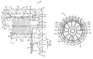
- FIG. 1 is a cross-sectional view of an electric motor module according to one embodiment of the invention.
- FIG. 2 is a side view of an end cap, according to one embodiment, for use with the electric motor module of FIG. 1 .
- FIG. 3 is a partial cross-section view of an electric motor module according to another embodiment of the invention.
- FIG. 4 is a side view of the end cap of FIG. 2 illustrating coolant flow patterns.
- FIG. 5 is a side view of an end cap, according to another embodiment of the invention, for use with the electric motor module of FIG. 3 .
- FIG. 6 is a side view of the end cap of FIG. 5 illustrating coolant flow patterns.
- FIG. 7 is a partial perspective view of the end cap of FIG. 5 .
- FIG. 8 is a partial perspective view of an end cap according to another embodiment of the invention.
- FIG. 1 illustrates an electric machine module 10 according to one embodiment of the invention.
- the electric machine module 10 can include a housing 12 comprising a sleeve member 14 , a first end cap 16 , and a second end cap 17 .
- An electric machine 18 can be housed within a machine cavity 20 at least partially defined by the sleeve member 14 and the end caps 16 , 17 .
- the sleeve member 14 and the end caps 16 , 17 can be coupled via fasteners (not shown), or another suitable coupling manner, to enclose at least a portion of the electric machine 18 within the machine cavity 20 .
- the end caps 16 , 17 can be identical parts. In other embodiments, the end caps 16 , 17 can include different individual features.
- the electric machine 18 can include a rotor 22 , a stator 24 , stator end turns 26 , and bearings 28 , and can be disposed about a main output shaft 30 . As shown in FIG. 1 , the stator 24 can circumscribe the rotor 22 . In some embodiments, the electric machine 18 can also include a rotor hub 32 or can have a “hub-less” design (not shown).
- the electric machine 18 can be, without limitation, an electric motor, such as a hybrid electric motor, an electric generator, or a vehicle alternator. In one embodiment, the electric machine 18 can be a High Voltage Hairpin (HVH) electric motor for use in a hybrid vehicle.
- HVH High Voltage Hairpin
- Components of the electric machine 18 such as, but not limited to, the stator end turns 26 , the rotor 22 , and the rotor hub 32 can generate heat during operation of the electric machine 18 . These components can be cooled to enhance the performance of and increase the lifespan of the electric machine 18 .
- the end caps 16 , 17 can be fabricated from cast aluminum, steel, stainless steel or similar materials.
- one or both of the end caps 16 , 17 can include a shroud 34 .
- the shroud 34 can be a generally ring-shaped extension, as shown in FIG. 2 , protruding axially inward into the machine cavity 20 , as shown in FIGS. 1 and 3 .
- the shroud 34 can extend the same axial distance inward along its radial circumference. In other embodiments, some radial portions of the shroud 34 can extend more or less inward than other radial portions of the shroud 34 (not shown).
- the shroud 34 can be cast as an integral part of the end cap 16 (and/or 17 ), or can be an additional piece bolted, welded or coupled to the end cap 16 in another suitable manner. As shown in FIGS. 1 and 3 , the shroud 34 can protrude axially inward near a radially inner surface of the stator end turns 26 . As a result, the sleeve member 14 , the end cap 16 (and/or 17 ) and the shroud 34 can be positioned to form a stator cavity 36 substantially surrounding each stator end turn 26 .
- a diameter of the shroud 34 can be substantially equal to an outer diameter 37 of the rotor 22 (as shown in FIG. 5 ). In another embodiment, the diameter of the shroud 34 can be greater than an inner diameter 39 of the rotor 22 (as shown in FIG. 5 ).
- the sleeve member 14 can include an inner coolant jacket 38 substantially circumscribing the stator 24 .
- a coolant such as water, ethylene glycol, a mixture of water and ethylene glycol, motor oil, hydraulic fluid oil, or a similar fluid, can be cycled through the coolant jacket 38 from a fluid source (not shown) to help remove heat from the electric machine 18 .
- the coolant can be pressurized when it enters the coolant jacket 38 from the fluid source.
- an inner wall 40 of the sleeve member 14 can include coolant apertures 42 in fluid communication with both the coolant jacket 38 and the stator cavity 36 .
- the coolant apertures 42 can allow the coolant inside the coolant jacket 38 to be dispersed into the stator cavity 38 toward the stator end turns 26 .
- the coolant can be dispersed over the stator end turns 26 to help remove heat energy from the stator end turns 26 and help cool the electric machine 18 .
- some of the coolant can reach the end caps 16 , 17 and/or the shroud 34 (e.g., some of the coolant directly from the coolant apertures 42 and/or some of the coolant which has splashed off the stator end turns 26 ) and can be redirected back toward the stator end turns 26 to further aid in cooling the electric machine 18 .
- the shroud 34 can help concentrate the coolant within the stator cavity 36 near the stator end turns 26 , which can also aid in further cooling the electric machine 18 .
- stator cavity 36 can be in fluid communication with the motor cavity 20 , and thus, a portion of the coolant may not deflect back onto the stator end turns 26 , but rather flow into the machine cavity 20 .
- some of the coolant along the end caps 16 , 17 can flow toward the shroud 34 (e.g., due to gravity).
- a portion of the coolant that reaches the shroud 34 e.g., from the end caps 16 , 17 , the coolant apertures 42 , and/or the stator end turns 26 ) can continue to flow downward due to gravity, following a substantially arcuate path created by a surface of the generally ring-shaped shroud 34 , as shown in FIG. 4 by arrows 43 .
- the coolant can flow along the substantially arcuate path until it reaches a “drop-off” region 45 .
- the drop-off region 45 can be a region, for example near a radially central portion of the electric machine 18 , where gravitational forces overcome the adhesive forces of the coolant to the surface of the shroud 34 . From the drop-off region 45 , the coolant can flow substantially straight down, away from the shroud 34 , and pool at or near a lower region of the electric machine 18 . The pooled coolant can flow through a drain (not shown) back to the fluid source where it can be cooled and sent back to the coolant jacket 38 .
- FIG. 5 illustrates a first end cap 16 according to another embodiment of the invention.
- the shroud 34 can include a step 44 at a point along the arcuate path of coolant flow generally before the drop-off region 45 .
- the step 44 can include a first surface 46 , which can be a generally radially-inward protrusion of the generally ring-shaped shroud 34 , and a second surface, or a rotor feed path 48 , which can be a radially outward protrusion from the first surface 46 .
- step 44 in the shroud 34 can eliminate the need for additional passageways in the end caps 16 , 17 or the main output shaft 30 which feed the coolant into the machine cavity 20 near the rotor 22 and the rotor hub 32 .
- the coolant can flow down the first surface 46 and reach the rotor feed path 48 prior to reaching the drop-off region 45 and flowing off the shroud 34 .
- the rotor feed path 48 can also be angled toward the main output shaft 30 .
- the rotor feed path 48 can be inclined by an angle “ ⁇ ” relative to a rotation axis 50 of the electric machine 18 . In some embodiments, the angle ⁇ can be between about thirty degrees and about sixty degrees.
- the angle ⁇ can be constant across the axial length of the rotor feed path 48 . More specifically, the rotor feed path 48 can include a substantially straight surface along the inward incline, as shown in FIGS. 3 and 7 . In other embodiments, the angle ⁇ can be variable (e.g., ranging between about thirty degrees and about sixty degrees) across the axial length of the rotor feed path 48 . More specifically, the rotor feed path 48 can include a substantially curved or stepped surface. For example, as shown in FIG. 8 , the angle ⁇ can decrease as the rotor feed path 48 extends axially inward from the end cap 16 , 17 to create a substantially curved surface.
- the orientation of the rotor feed path 48 can serve as a funnel-type element to change a direction of the coolant.
- the rotor feed path 48 can redirect the coolant flow into the machine cavity 20 toward the rotor 22 and/or the rotor hub 32 . More specifically, due to gravity, the coolant can flow down the angled rotor feed path 48 toward the rotor 22 and/or the rotor hub 32 .
- the substantially curved surface of the rotor feed path 48 can cause the coolant to flow toward the rotor 22 and/or the rotor hub 32 at an increased axial velocity (compared to a straight inclined surface), which can help prevent the coolant from reaching an air gap formed between the stationary stator 24 and the rotating rotor 22 .
- the coolant either reaching or in proximity to the rotor 22 and/or the rotor hub 32 , can help remove heat from the rotor 22 and the rotor hub 32 to further aid in cooling the electric machine 18 .
- the coolant After flowing throughout the motor cavity 20 , the coolant can pool at or near the lower region of the electric machine 18 .
- the pooled coolant can flow through the drain back to the fluid source where it can be cooled and recycled back to the coolant jacket 38 .
- a heat transfer element e.g., a radiator, a heat exchanger, or a similar element
- the housing 12 can comprise a substantially cylindrical canister substantially enclosing the electric machine and a single end cap (not shown).
- an axial wall of the canister and the single end cap can each include the shroud 34 .
- a radial wall of the canister can include the coolant jacket 38 and the coolant apertures 42 .
- the coolant jacket 38 and the coolant apertures 42 can be separate and substantially enclosed by the housing 12 .
Landscapes
- Engineering & Computer Science (AREA)
- Power Engineering (AREA)
- Motor Or Generator Cooling System (AREA)
- Motor Or Generator Frames (AREA)
Abstract
Description
Claims (15)
Priority Applications (2)
| Application Number | Priority Date | Filing Date | Title |
|---|---|---|---|
| US12/796,596 US8456046B2 (en) | 2010-06-08 | 2010-06-08 | Gravity fed oil cooling for an electric machine |
| PCT/US2011/039390 WO2011156332A2 (en) | 2010-06-08 | 2011-06-07 | Gravity fed oil cooling for an electric machine |
Applications Claiming Priority (1)
| Application Number | Priority Date | Filing Date | Title |
|---|---|---|---|
| US12/796,596 US8456046B2 (en) | 2010-06-08 | 2010-06-08 | Gravity fed oil cooling for an electric machine |
Publications (2)
| Publication Number | Publication Date |
|---|---|
| US20110298318A1 US20110298318A1 (en) | 2011-12-08 |
| US8456046B2 true US8456046B2 (en) | 2013-06-04 |
Family
ID=45063916
Family Applications (1)
| Application Number | Title | Priority Date | Filing Date |
|---|---|---|---|
| US12/796,596 Active 2030-10-22 US8456046B2 (en) | 2010-06-08 | 2010-06-08 | Gravity fed oil cooling for an electric machine |
Country Status (2)
| Country | Link |
|---|---|
| US (1) | US8456046B2 (en) |
| WO (1) | WO2011156332A2 (en) |
Cited By (8)
| Publication number | Priority date | Publication date | Assignee | Title |
|---|---|---|---|---|
| US20130002067A1 (en) * | 2011-06-30 | 2013-01-03 | Bradfield Michael D | Electric Machine Module Cooling System and Method |
| US20130038150A1 (en) * | 2011-08-10 | 2013-02-14 | Bradley D. Chamberlin | Electric machine module cooling system and method |
| US20130106212A1 (en) * | 2011-10-27 | 2013-05-02 | Kabushiki Kaisha Kobe Seiko Sho (Kobe Steel, Ltd.) | Motor having heat transfer sheet |
| US20130154408A1 (en) * | 2011-03-31 | 2013-06-20 | Komatsu Ltd. | Generator motor cooling structure and generator motor |
| US20160322876A1 (en) * | 2014-01-17 | 2016-11-03 | Mitsubishi Electric Corporation | Rotary electric machine |
| US20180048207A1 (en) * | 2015-04-27 | 2018-02-15 | Mitsubishi Electric Corporation | Rotary electric machine |
| US10439477B2 (en) | 2014-01-31 | 2019-10-08 | Tesla, Inc. | Pressurized and gravity-fed liquid cooling of electric motor |
| US11984787B2 (en) | 2020-01-31 | 2024-05-14 | Ford Global Technologies, Llc | Motor end cap design that functions as a lube distributor in hybrid transmissions |
Families Citing this family (14)
| Publication number | Priority date | Publication date | Assignee | Title |
|---|---|---|---|---|
| FR2984810B1 (en) * | 2011-12-23 | 2015-06-19 | Valeo Systemes Thermiques | AIR COOLING DEVICE OF A PULLER FOR HEATING, VENTILATION AND AIR CONDITIONING APPARATUS |
| DE102012100646B4 (en) * | 2012-01-26 | 2017-03-16 | Saxess Holding Gmbh | Turbine and generator housing |
| US10069375B2 (en) * | 2012-05-02 | 2018-09-04 | Borgwarner Inc. | Electric machine module cooling system and method |
| US9006943B2 (en) * | 2012-09-12 | 2015-04-14 | Remy Technologies, L.L.C. | Electro-dynamic machine with coolant chargeable bladder |
| TWI590568B (en) * | 2013-12-31 | 2017-07-01 | 鴻海精密工業股份有限公司 | Motor |
| SE538971C2 (en) * | 2015-06-16 | 2017-03-07 | Scania Cv Ab | Arrangement for distributing oil in an electric machine |
| FR3060895B1 (en) * | 2016-12-19 | 2019-11-22 | Valeo Equipements Electriques Moteur | ROTATING ELECTRICAL MACHINE WITH IMPROVED COOLING |
| CN110323895B (en) * | 2018-03-28 | 2021-07-27 | 上海汽车集团股份有限公司 | Pure electric vehicles actuating system and driving motor oil cooling system thereof |
| US20240055915A1 (en) * | 2019-01-16 | 2024-02-15 | Borgwarner Inc. | Integrated stator cooling jacket system |
| DE102019113091A1 (en) * | 2019-05-17 | 2020-11-19 | Valeo Siemens Eautomotive Germany Gmbh | Guide device for a winding head of an electrical machine, cooling fluid flowing around and electrical machine |
| US12088149B2 (en) | 2021-12-02 | 2024-09-10 | Borgwarner Inc. | Cooling system for an electric machine |
| CN114552853B (en) * | 2022-03-25 | 2022-08-05 | 绍兴上虞五州电机制造有限公司 | Water-cooled motor with double cooling circulation systems |
| DE102023204077A1 (en) | 2023-05-03 | 2024-11-07 | Volkswagen Aktiengesellschaft | Electric Machine |
| CN117240006B (en) * | 2023-09-21 | 2024-05-14 | 深圳沃新智创科技有限公司 | Cooling motor system with temperature monitoring function |
Citations (190)
| Publication number | Priority date | Publication date | Assignee | Title |
|---|---|---|---|---|
| US2080678A (en) | 1936-02-15 | 1937-05-18 | Byron Jackson Co | Motor construction |
| US2264616A (en) | 1938-09-21 | 1941-12-02 | John C Buckbee | Rotary compressor |
| US2891391A (en) * | 1957-08-26 | 1959-06-23 | Vilter Mfg Co | Refrigerated hermetically sealed motors |
| US2947892A (en) * | 1958-02-12 | 1960-08-02 | Gen Electric Canada | Ventilation of totally enclosed motors |
| US2951954A (en) * | 1959-02-12 | 1960-09-06 | Gen Electric | Fluid-coupled rotor for dynamoelectric machine |
| US3007064A (en) * | 1958-04-04 | 1961-10-31 | Task Corp | Liquid cooled rotor and stator |
| US3110827A (en) * | 1960-08-12 | 1963-11-12 | Westinghouse Electric Corp | Dynamoelectric machine |
| US3188833A (en) * | 1959-11-23 | 1965-06-15 | Allis Louis Co | Electric motor with improved cooling means |
| US3435263A (en) * | 1966-05-04 | 1969-03-25 | Gen Electric | Gap pickup rotor with radially extended outlets |
| US3439202A (en) * | 1966-04-07 | 1969-04-15 | Licentia Gmbh | Cooling system for electrical generators |
| US3447002A (en) | 1965-03-17 | 1969-05-27 | Asea Ab | Rotating electrical machine with liquid-cooled laminated stator core |
| US3525001A (en) | 1968-09-23 | 1970-08-18 | Preco Inc | Liquid cooled electric motor |
| US3558943A (en) * | 1968-09-11 | 1971-01-26 | Electrolux Ab | Air cooled rotor for dynamo-electric machine |
| US3643119A (en) * | 1970-11-05 | 1972-02-15 | Gen Electric | Ventilated dynamoelectric machine |
| US3701911A (en) * | 1971-05-20 | 1972-10-31 | Skf Ind Trading & Dev | Motor bearing support and cooling means |
| US3748507A (en) * | 1971-12-02 | 1973-07-24 | Gen Electric | Variable speed drive having enhanced ventilation |
| US3800173A (en) * | 1972-09-19 | 1974-03-26 | Gen Electric | Dynamoelectric machine having improved ventilation |
| US3932778A (en) * | 1973-04-09 | 1976-01-13 | Hitachi, Ltd. | Cooling device for an electric rotary machine |
| US4038570A (en) | 1974-03-20 | 1977-07-26 | Durley Iii Benton A | Ultrasonic piezoelectric transducer drive circuit |
| US4301386A (en) * | 1977-08-12 | 1981-11-17 | General Electric Co. | Rotor laminae assembly for a cast rotor dynamoelectric machine |
| US4365178A (en) * | 1981-06-08 | 1982-12-21 | General Electric Co. | Laminated rotor for a dynamoelectric machine with coolant passageways therein |
| US4547688A (en) * | 1984-05-07 | 1985-10-15 | Westinghouse Electric Corp. | Dynamoelectric machine with rotor ventilation system including prewhirl inlet guide vanes |
| US4745315A (en) * | 1983-12-15 | 1988-05-17 | General Electric Company | Brushless exciter with zero-gravity rectifier assembly |
| US4845394A (en) * | 1987-07-17 | 1989-07-04 | Siemens Aktiengesellschaft | Electric machine with a closed cooling loop |
| US5019733A (en) * | 1987-09-25 | 1991-05-28 | Honda Giken Kogyo Kabushiki Kaisha | AC generator |
| US5081382A (en) * | 1990-10-01 | 1992-01-14 | Sundstrand Corporation | Generator end turn cooling using oil flow control tubes |
| US5180004A (en) * | 1992-06-19 | 1993-01-19 | General Motors Corporation | Integral heater-evaporator core |
| JPH05103445A (en) | 1991-10-05 | 1993-04-23 | Fanuc Ltd | Liquid-cooled motor and its jacket |
| US5207121A (en) * | 1992-02-13 | 1993-05-04 | General Motors Corporation | Gear case for locomotive drive system |
| JPH05292704A (en) | 1992-04-14 | 1993-11-05 | Toshiba Corp | Rotor abnormality monitor |
| US5293089A (en) | 1989-12-15 | 1994-03-08 | Robert Bosch Gmbh | Liquid-cooled electric generator |
| JPH0636364U (en) | 1992-10-13 | 1994-05-13 | 神鋼電機株式会社 | Cooling mechanism for outer-rotor type high-speed rotating electric machine |
| US5319272A (en) * | 1992-07-14 | 1994-06-07 | Eemco/Datron, Inc. | Miniature rotating rectifier assembly |
| JPH06311691A (en) | 1993-04-15 | 1994-11-04 | Meidensha Corp | Motor for electric car |
| US5372213A (en) * | 1991-10-24 | 1994-12-13 | Aisin Aw Co., Ltd. | Oil circulating system for electric vehicle |
| JPH07264810A (en) | 1994-03-17 | 1995-10-13 | Okuma Mach Works Ltd | Liquid-cooled motor |
| JPH0819218A (en) | 1994-06-28 | 1996-01-19 | Honda Motor Co Ltd | Cooling structure for rotating electric machine |
| US5519269A (en) | 1994-06-10 | 1996-05-21 | Westinghouse Electric Corp. | Electric induction motor and related method of cooling |
| US5557153A (en) * | 1993-09-15 | 1996-09-17 | Abb Management Ag | Air-cooled rotating electrical machine |
| JPH0946973A (en) | 1995-07-28 | 1997-02-14 | Nikkiso Co Ltd | Rotor cooling construction for motor |
| US5616973A (en) | 1994-06-29 | 1997-04-01 | Yeomans Chicago Corporation | Pump motor housing with improved cooling means |
| JPH09154257A (en) | 1995-11-28 | 1997-06-10 | Nippei Toyama Corp | Built-in motor |
| KR970055103A (en) | 1995-12-29 | 1997-07-31 | 이우복 | Cooling device of permanent magnet synchronous motor |
| US5757094A (en) * | 1997-03-28 | 1998-05-26 | General Electric Canada Inc. | Ventilation system for an AC machine having overhanging salient poles with juxtaposed shrouds |
| JPH10234157A (en) | 1997-02-19 | 1998-09-02 | Toshiba Corp | Motor |
| US5859482A (en) | 1997-02-14 | 1999-01-12 | General Electric Company | Liquid cooled electric motor frame |
| US5889342A (en) * | 1995-12-21 | 1999-03-30 | Aisin Aw Co., Ltd. | Motor cooling circuit |
| JPH11132867A (en) | 1997-09-10 | 1999-05-21 | Pfeiffer Vacuum Gmbh | Temperature-monitoring device |
| US5923108A (en) | 1996-07-30 | 1999-07-13 | Ebara Corporation | Canned motor |
| JPH11206063A (en) | 1997-12-26 | 1999-07-30 | Toyota Motor Corp | Electrical machine, power transmission device and their manufacture |
| US5937817A (en) | 1998-06-23 | 1999-08-17 | Harley-Davidson Motor Company | Dry sump oil cooling system |
| US5965965A (en) * | 1997-05-26 | 1999-10-12 | Denso Corporation | Stator winding arrangement of alternator for vehicle |
| US6011332A (en) * | 1997-05-26 | 2000-01-04 | Denso Corporation | Stator cooling arrangement of alternator for vehicle |
| KR20000013908A (en) | 1998-08-14 | 2000-03-06 | 에릭 발리베 | Cooling system of alternating current generator for cars |
| JP2000152561A (en) | 1998-11-10 | 2000-05-30 | Toshiba Transport Eng Inc | Ventilation filter and ventilation cooling type dynamo electric machine provided with ventilation filter |
| JP2000152563A (en) | 1998-11-09 | 2000-05-30 | Railway Technical Res Inst | Totally enclosed cooling type dynamo electric machine |
| US6069424A (en) * | 1996-05-02 | 2000-05-30 | Chrysler Corporation | Stator cooling |
| US6075304A (en) | 1997-04-30 | 2000-06-13 | Alon Co., Ltd | Stator with molded encasement for small motors and manufacturing process therefor |
| US6087746A (en) | 1997-06-19 | 2000-07-11 | Valeo Equipements Electriques Moteur | Alternator with improved cooling means, especially for motor vehicles |
| US6095754A (en) | 1998-05-06 | 2000-08-01 | Applied Materials, Inc. | Turbo-Molecular pump with metal matrix composite rotor and stator |
| US6097130A (en) * | 1997-05-26 | 2000-08-01 | Denso Corporation | Alternator for vehicle |
| US6114784A (en) | 1998-06-22 | 2000-09-05 | Nissan Motor Co., Ltd. | Motor with cooling structure |
| US6147430A (en) * | 1998-05-25 | 2000-11-14 | Denso Corporation | Stator of AC generator for vehicle |
| US6147432A (en) * | 1998-08-06 | 2000-11-14 | Denso Corporation | AC generator stator for vehicle |
| JP2000324757A (en) | 1999-05-07 | 2000-11-24 | Toshiba Corp | Outer rotor type of motor |
| JP2000333409A (en) | 1999-05-21 | 2000-11-30 | Matsushita Electric Ind Co Ltd | Induction motor |
| US6173758B1 (en) * | 1999-08-02 | 2001-01-16 | General Motors Corporation | Pin fin heat sink and pin fin arrangement therein |
| US6181043B1 (en) * | 1997-12-10 | 2001-01-30 | Denso Corporation | Alternator for vehicle |
| US6201321B1 (en) | 1998-06-05 | 2001-03-13 | Bayside Controls, Inc. | Apparatus and method for dissipating heat from a motor |
| US6208060B1 (en) * | 1998-05-25 | 2001-03-27 | Denso Corporation | Stator of vehicle AC generator and method of manufacturing the same |
| US6232687B1 (en) * | 1999-03-25 | 2001-05-15 | General Electric Company | Electric motor having snap connection assembly |
| US6242836B1 (en) * | 1998-06-26 | 2001-06-05 | Denso Corporation | Vehicle AC generators stator and method of manufacturing the same |
| US6291918B1 (en) * | 1997-05-26 | 2001-09-18 | Denso Corporation | Alternator for vehicle |
| US6300693B1 (en) | 1999-03-05 | 2001-10-09 | Emerson Electric Co. | Electric motor cooling jacket assembly and method of manufacture |
| US6313559B1 (en) * | 1999-04-14 | 2001-11-06 | Denso Corporation | Stator arrangement of rotary electric machine |
| JP2001333559A (en) | 2000-05-19 | 2001-11-30 | Nissan Motor Co Ltd | Motor stator |
| US6333573B1 (en) * | 1999-07-12 | 2001-12-25 | Denso Corporation | Rotary electric machine having resin covered joined portions |
| US20010054852A1 (en) * | 2000-06-21 | 2001-12-27 | Denso Corporation | Cooling arrangement of vehicle rotary electric machine |
| US6335583B1 (en) * | 1998-05-25 | 2002-01-01 | Denso Corporation | Stator of vehicle AC generator and method of manufacturing the same |
| US6340853B1 (en) * | 2000-03-13 | 2002-01-22 | Hitachi, Ltd. | Electric rotating machine |
| US6346758B1 (en) * | 1999-07-12 | 2002-02-12 | Denso Corporation | Rotary electric machine and method of manufacturing the same |
| US6359232B1 (en) | 1996-12-19 | 2002-03-19 | General Electric Company | Electrical insulating material and stator bar formed therewith |
| JP2002095217A (en) | 2000-09-18 | 2002-03-29 | Hitachi Ltd | Vehicle ac generator |
| JP2002119019A (en) | 2000-10-11 | 2002-04-19 | Honda Motor Co Ltd | Cooling structure of motor |
| US6404628B1 (en) * | 2000-07-21 | 2002-06-11 | General Motors Corporation | Integrated power electronics cooling housing |
| US6417592B2 (en) * | 1999-12-09 | 2002-07-09 | Denso Corporation | Rotary electric machine for vehicle |
| US20020130566A1 (en) * | 2001-03-15 | 2002-09-19 | Siemens Aktiengesellschaft | Air-cooled electric rotary machine |
| US6459177B1 (en) * | 1999-08-06 | 2002-10-01 | Denso Corporation | Electric rotary machine having a plurality of conductor segments and method of manufacturing the same |
| US20020149273A1 (en) * | 2001-04-06 | 2002-10-17 | Viktor Soitu | Electric asynchronous motor |
| JP2003009467A (en) * | 2001-06-22 | 2003-01-10 | Nissan Motor Co Ltd | Motor cooling mechanism |
| US20030011253A1 (en) * | 1999-08-16 | 2003-01-16 | Kalsi Swarn S. | Thermally-conductive stator support structure |
| US6509665B1 (en) | 1999-10-25 | 2003-01-21 | Matsushita Electric Industial Co., Ltd. | Motor having stator with insulator of high heat-conductivity |
| US6515392B2 (en) * | 2000-11-30 | 2003-02-04 | Denso Corporation | Vehicle AC generator |
| US6522043B2 (en) * | 2001-01-19 | 2003-02-18 | Denso Corporation | Vehicle AC generator |
| US20030038549A1 (en) * | 1996-10-08 | 2003-02-27 | Juha Pyrhonen | Electric machine construction and a method for an electric machine |
| US20030048030A1 (en) * | 1999-10-19 | 2003-03-13 | Griffith John Wesley | Generator stator core vent duct spacer posts |
| US6559572B2 (en) * | 2000-04-14 | 2003-05-06 | Denso Corporation | Stator core of vehicle rotary electric machine and method of manufacturing the same |
| JP2003169448A (en) * | 2001-12-03 | 2003-06-13 | Nissan Motor Co Ltd | Driver for hybrid vehicle |
| US6579202B2 (en) * | 2000-12-18 | 2003-06-17 | General Motors Corporation | Lubrication and cooling system for power receiving and delivery units in an electro-mechanical vehicular transmission |
| JP2003250247A (en) | 2002-02-22 | 2003-09-05 | Nissan Motor Co Ltd | Cooling apparatus of motor |
| JP2003299317A (en) | 2002-04-03 | 2003-10-17 | Toyota Motor Corp | Rotating means for driving vehicle |
| JP2003324901A (en) | 2002-04-26 | 2003-11-14 | Nippon Soken Inc | Motor |
| US20030222519A1 (en) | 2002-05-28 | 2003-12-04 | Emerson Electric Co. | Cooling jacket for electric machines |
| US20040032172A1 (en) * | 2002-08-13 | 2004-02-19 | General Electric Company | Generator gas shield and related method |
| US20040036367A1 (en) * | 2002-01-30 | 2004-02-26 | Darin Denton | Rotor cooling apparatus |
| US20040066099A1 (en) * | 2002-10-08 | 2004-04-08 | Weeber Konrad Roman | Forced air stator ventilation system and stator ventilation method for superconducting synchronous machine |
| JP2004215353A (en) | 2002-12-27 | 2004-07-29 | Toyota Motor Corp | Rotary electric machine |
| US6770999B2 (en) * | 2002-03-01 | 2004-08-03 | Denso Corporation | Stator of vehicle ac generator |
| JP2004236376A (en) | 2003-01-28 | 2004-08-19 | Nissan Motor Co Ltd | Internal cooling type motor |
| US6779799B2 (en) * | 2002-11-27 | 2004-08-24 | General Electric Company | Sealing apparatus for electrical generator ventilation system |
| JP2004248402A (en) | 2003-02-13 | 2004-09-02 | Toyota Motor Corp | Driver for vehicle |
| US20040189110A1 (en) | 1999-09-03 | 2004-09-30 | Kazumasa Ide | Rotating electric machine and cooling method thereof |
| US20040195929A1 (en) | 2003-04-04 | 2004-10-07 | Nissan Motor Co., Ltd. | Stator of two rotor single stator type electric motor |
| JP2004297924A (en) | 2003-03-27 | 2004-10-21 | Nissan Motor Co Ltd | Cooling structure of rotary electric machine |
| JP2004312886A (en) | 2003-04-08 | 2004-11-04 | Suzuki Motor Corp | Cooling structure of electric motor |
| JP2004357472A (en) | 2003-05-30 | 2004-12-16 | Suzuki Motor Corp | Cooling structure of motor |
| JP2005012989A (en) | 2003-05-28 | 2005-01-13 | Toyota Motor Corp | Cooling structure of stator in rotating electric machine |
| US20050023266A1 (en) | 2002-02-25 | 2005-02-03 | Futek Furnace Inc. | Heat treatment apparatus and method |
| US20050023909A1 (en) | 2002-06-13 | 2005-02-03 | Cromas Joseph Charles | Automotive generator |
| JP2005057957A (en) | 2003-08-07 | 2005-03-03 | Kawasaki Heavy Ind Ltd | Motor |
| US6897594B2 (en) * | 2002-01-18 | 2005-05-24 | Denso Corporation | Stator for a vehicular rotary electric machine and a manufacturing method thereof |
| US6903471B2 (en) | 2002-04-01 | 2005-06-07 | Nissan Motor Co., Ltd. | Stator cooling structure for multi-shaft, multi-layer electric motor |
| JP2005168265A (en) | 2003-12-05 | 2005-06-23 | Nissan Motor Co Ltd | Cooling structure for rotary electric machine |
| US20050151430A1 (en) * | 2004-01-09 | 2005-07-14 | Siemens Westinghouse Power Corporation | Cam locked air gap baffle assembly for a dynamoelectric machine |
| US20050194551A1 (en) | 2002-06-18 | 2005-09-08 | Siemens Aktiengesellschaft | Corona shield, and method of making a corona shield |
| US20050206251A1 (en) * | 2004-03-22 | 2005-09-22 | Foster Michael D | Electric motor/generator and method of cooling an electromechanical transmission |
| US20050274450A1 (en) | 2004-06-15 | 2005-12-15 | Smith James B | Compression of resin impregnated insulating tapes |
| US20050285456A1 (en) | 2002-09-27 | 2005-12-29 | Hitachi, Ltd. | Method of manufacturing a resin-molded stator |
| US20060024178A1 (en) * | 2004-07-30 | 2006-02-02 | Samsung Techwin Co., Ltd. | Turbo generator and fuel cell system having the same |
| US6998749B2 (en) * | 2002-07-11 | 2006-02-14 | Denso Corporation | Rotary electric machine |
| US7002267B2 (en) * | 2004-03-22 | 2006-02-21 | General Motors Corporation | Method and apparatus for cooling a hybrid transmission electric motor |
| JP2006060914A (en) | 2004-08-19 | 2006-03-02 | Mitsubishi Motors Corp | Motor cooling structure and manufacturing method thereof |
| US20060055255A1 (en) * | 2001-03-07 | 2006-03-16 | Hitachi, Ltd. | Electric rotating machine |
| US7026733B2 (en) | 2002-02-22 | 2006-04-11 | Daimlerchrysler Ag | Drive system for a motor vehicle having an electric machine |
| US7071586B2 (en) * | 2001-03-07 | 2006-07-04 | Hitachi, Ltd. | Dynamo-electric machine |
| JP2006297541A (en) | 2005-04-20 | 2006-11-02 | Nsk Ltd | Rotary shaft device of machine tool |
| JP2006528879A (en) | 2003-05-26 | 2006-12-21 | ヴァレオ エキプマン エレクトリク モトゥール | Rotating electrical machines such as automotive alternators |
| US20070024130A1 (en) | 2003-08-01 | 2007-02-01 | Siemens Aktiengesellschaft | Electric machine with rotor cooling and corresponding cooling method |
| US7173358B2 (en) * | 2002-08-16 | 2007-02-06 | Alstom Technology Ltd. | Rotor for an electrical machine |
| US20070052313A1 (en) | 2005-09-07 | 2007-03-08 | Kabushiki Kaisha Toshiba | Rotating electrical machine |
| US20070063607A1 (en) | 2005-09-21 | 2007-03-22 | Toyota Jidosha Kabushiki Kaisha | Permanent magnet type rotating electric machine capable of suppressing deformation of rotor core |
| US20070096588A1 (en) * | 2003-12-23 | 2007-05-03 | Siemens Aktiengesellschaft | Rotary support with elastic connection device for installation of electric machines in tubes |
| US20070096590A1 (en) * | 2005-10-28 | 2007-05-03 | General Electric Company | Paddled rotor spaceblocks |
| US20070126296A1 (en) * | 2005-12-02 | 2007-06-07 | Delta Electronics, Inc. | Stator structure and manufacturing method thereof |
| US20070149073A1 (en) | 2002-06-18 | 2007-06-28 | Siemens Aktiengesellschaft | Electric machine with a corona shield |
| US20070145836A1 (en) | 2005-12-22 | 2007-06-28 | Emerson Electric Co. | Winding lead cooling for motor with heat-sensitive electronic components |
| US7239055B2 (en) * | 2004-07-28 | 2007-07-03 | Gm Global Technology Operations, Inc. | Motor cooling system |
| US20070216236A1 (en) | 2006-03-14 | 2007-09-20 | Ward Terence G | Method and apparatus for heat removal from electric motor winding end-turns |
| US7276006B2 (en) * | 2004-03-22 | 2007-10-02 | General Motors Corporation | Transmission case for lube return and method |
| US20070236094A1 (en) * | 2006-04-07 | 2007-10-11 | General Electric Company | Methods and apparatus for using an electrical machine to transport fluids through a pipeline |
| US7284313B2 (en) * | 2004-03-22 | 2007-10-23 | General Motors Corporation | Method for assembling a hybrid electro-mechanical transmission |
| JP2007282341A (en) | 2006-04-04 | 2007-10-25 | Shimadzu Corp | Motor equipped with cooling mechanism |
| US20070252473A1 (en) * | 2006-04-28 | 2007-11-01 | Kabushiki Kaisha Toshiba | Dynamo-electric machine rotor |
| US7339300B2 (en) * | 2004-07-28 | 2008-03-04 | Gm Global Technology Operations, Inc. | Structural support member for stator retention and method of assembling an electromechanical transmission |
| US7352091B2 (en) * | 2004-09-01 | 2008-04-01 | Remy International, Inc. | Electronic package for electrical machine |
| US7402923B2 (en) | 2004-07-29 | 2008-07-22 | General Motors Corporation | Electrically variable transmission |
| JP2008206213A (en) | 2007-02-16 | 2008-09-04 | Mitsubishi Motors Corp | Electric motor structure for electric vehicle |
| JP2008219960A (en) | 2007-02-28 | 2008-09-18 | Toyota Central R&D Labs Inc | Rotary electric machine |
| US20080223557A1 (en) | 2007-03-16 | 2008-09-18 | Remy Technologies, L.L.C. | Liquid cooling system of an electric machine |
| US20080252169A1 (en) * | 2004-10-05 | 2008-10-16 | Masafumi Fujita | Rotary electro-dynamic machine and armature winding thereof |
| JP2008544733A (en) | 2005-06-16 | 2008-12-04 | シーメンス アクチエンゲゼルシヤフト | Rotor-cooled permanent magnet excitation type electric machine |
| US7462962B2 (en) * | 2005-06-13 | 2008-12-09 | General Electric Company | Cooling system for an electrical machine with center rotor cooling dusts |
| US20090033161A1 (en) * | 2007-08-02 | 2009-02-05 | Remy International, Inc. | Airflow cooling pattern for belt-driven vehicle electrical power generator |
| US20090033160A1 (en) * | 2007-07-31 | 2009-02-05 | Daniel Mueller | Electric motor for hybrid or electric vehicle |
| US20090108714A1 (en) * | 2007-10-24 | 2009-04-30 | Michel Fakes | Bearing and cover assembly for a rotating electrical machine and a rotating electrical machine containing such an assembly |
| US20090121562A1 (en) | 2007-11-09 | 2009-05-14 | Hyundai Motor Company | Device and method for cooling motor for hybrid electric vehicles |
| US7538457B2 (en) * | 2006-01-27 | 2009-05-26 | General Motors Corporation | Electric motor assemblies with coolant flow for concentrated windings |
| US20090174278A1 (en) | 2008-01-08 | 2009-07-09 | General Electric Company | Stator Bar Components with High Thermal Conductivity |
| US20090206687A1 (en) | 2008-02-15 | 2009-08-20 | Gm Global Technology Operations, Inc. | Cooling systems and methods for integrated electric motor-inverters |
| US7592045B2 (en) | 2004-06-15 | 2009-09-22 | Siemens Energy, Inc. | Seeding of HTC fillers to form dendritic structures |
| JP2009247084A (en) | 2008-03-31 | 2009-10-22 | Hitachi Ltd | Rotary electric machine and vehicle |
| JP2009247085A (en) | 2008-03-31 | 2009-10-22 | Hitachi Ltd | Rotary electric machine |
| JP2009254205A (en) | 2008-04-10 | 2009-10-29 | Mitsuba Corp | Electric motor |
| US7615903B2 (en) * | 2006-04-27 | 2009-11-10 | Gm Global Technology Operations, Inc. | Structural support member for electric motor/generator in electromechanical transmission |
| US7615951B2 (en) * | 2006-09-08 | 2009-11-10 | Gm Global Technology Operations, Inc. | Method and system for limiting the operating temperature of an electric motor |
| JP2010028908A (en) | 2008-07-16 | 2010-02-04 | Toyota Motor Corp | Rotor of rotating electrical machine |
| JP2010028958A (en) | 2008-07-17 | 2010-02-04 | Toyota Motor Corp | Rotating electrical machine and cooling system of rotating electrical machine |
| US20100026111A1 (en) | 2006-09-22 | 2010-02-04 | Siemens Aktiengesellschaft | Stator for an electrical machine with liquid cooling |
| JP2010035265A (en) | 2008-07-25 | 2010-02-12 | Meidensha Corp | Temperature-measuring device for rotor of electric motor |
| JP2010063253A (en) | 2008-09-03 | 2010-03-18 | Toyota Motor Corp | Rotor |
| US20100102649A1 (en) | 2008-10-24 | 2010-04-29 | Deere & Company | Hydroformed cooling channels in stator laminations |
| US20100109454A1 (en) | 2008-11-06 | 2010-05-06 | Emerson Electric Co. | Liquid deflecting baffle for an electric motor |
| JP2010121701A (en) | 2008-11-19 | 2010-06-03 | Ntn Corp | In-wheel motor driving device |
| US20100176668A1 (en) | 2009-01-15 | 2010-07-15 | Aisin Aw Co., Ltd. | Stator |
| US20110050141A1 (en) | 2009-08-31 | 2011-03-03 | Gm Global Technology Operations, Inc. | Electric motor stator winding temperature estimation |
| US20110101700A1 (en) | 2009-11-05 | 2011-05-05 | Henrik Stiesdal | Arrangement for Cooling of an Electrical Machine |
| US7939975B2 (en) | 2007-10-26 | 2011-05-10 | E. I Du Pont De Nemours And Company | Over-mold stator assembly and process for preparation thereof |
| US20110109095A1 (en) | 2009-11-06 | 2011-05-12 | Henrik Stiesdal | Arrangement for cooling of an electrical generator |
| US8067865B2 (en) | 2008-10-28 | 2011-11-29 | Caterpillar Inc. | Electric motor/generator low hydraulic resistance cooling mechanism |
| US8068327B2 (en) | 2005-07-25 | 2011-11-29 | Lenze Drives Gmbh | Holding device for encased high-protective capacitors |
Family Cites Families (1)
| Publication number | Priority date | Publication date | Assignee | Title |
|---|---|---|---|---|
| JP4891688B2 (en) * | 2006-07-24 | 2012-03-07 | 株式会社東芝 | Fully enclosed motor |
-
2010
- 2010-06-08 US US12/796,596 patent/US8456046B2/en active Active
-
2011
- 2011-06-07 WO PCT/US2011/039390 patent/WO2011156332A2/en active Application Filing
Patent Citations (199)
| Publication number | Priority date | Publication date | Assignee | Title |
|---|---|---|---|---|
| US2080678A (en) | 1936-02-15 | 1937-05-18 | Byron Jackson Co | Motor construction |
| US2264616A (en) | 1938-09-21 | 1941-12-02 | John C Buckbee | Rotary compressor |
| US2891391A (en) * | 1957-08-26 | 1959-06-23 | Vilter Mfg Co | Refrigerated hermetically sealed motors |
| US2947892A (en) * | 1958-02-12 | 1960-08-02 | Gen Electric Canada | Ventilation of totally enclosed motors |
| US3007064A (en) * | 1958-04-04 | 1961-10-31 | Task Corp | Liquid cooled rotor and stator |
| US2951954A (en) * | 1959-02-12 | 1960-09-06 | Gen Electric | Fluid-coupled rotor for dynamoelectric machine |
| US3188833A (en) * | 1959-11-23 | 1965-06-15 | Allis Louis Co | Electric motor with improved cooling means |
| US3110827A (en) * | 1960-08-12 | 1963-11-12 | Westinghouse Electric Corp | Dynamoelectric machine |
| US3447002A (en) | 1965-03-17 | 1969-05-27 | Asea Ab | Rotating electrical machine with liquid-cooled laminated stator core |
| US3439202A (en) * | 1966-04-07 | 1969-04-15 | Licentia Gmbh | Cooling system for electrical generators |
| US3435263A (en) * | 1966-05-04 | 1969-03-25 | Gen Electric | Gap pickup rotor with radially extended outlets |
| US3558943A (en) * | 1968-09-11 | 1971-01-26 | Electrolux Ab | Air cooled rotor for dynamo-electric machine |
| US3525001A (en) | 1968-09-23 | 1970-08-18 | Preco Inc | Liquid cooled electric motor |
| US3643119A (en) * | 1970-11-05 | 1972-02-15 | Gen Electric | Ventilated dynamoelectric machine |
| US3701911A (en) * | 1971-05-20 | 1972-10-31 | Skf Ind Trading & Dev | Motor bearing support and cooling means |
| US3748507A (en) * | 1971-12-02 | 1973-07-24 | Gen Electric | Variable speed drive having enhanced ventilation |
| US3800173A (en) * | 1972-09-19 | 1974-03-26 | Gen Electric | Dynamoelectric machine having improved ventilation |
| US3932778A (en) * | 1973-04-09 | 1976-01-13 | Hitachi, Ltd. | Cooling device for an electric rotary machine |
| US4038570A (en) | 1974-03-20 | 1977-07-26 | Durley Iii Benton A | Ultrasonic piezoelectric transducer drive circuit |
| US4301386A (en) * | 1977-08-12 | 1981-11-17 | General Electric Co. | Rotor laminae assembly for a cast rotor dynamoelectric machine |
| US4365178A (en) * | 1981-06-08 | 1982-12-21 | General Electric Co. | Laminated rotor for a dynamoelectric machine with coolant passageways therein |
| US4745315A (en) * | 1983-12-15 | 1988-05-17 | General Electric Company | Brushless exciter with zero-gravity rectifier assembly |
| US4547688A (en) * | 1984-05-07 | 1985-10-15 | Westinghouse Electric Corp. | Dynamoelectric machine with rotor ventilation system including prewhirl inlet guide vanes |
| US4845394A (en) * | 1987-07-17 | 1989-07-04 | Siemens Aktiengesellschaft | Electric machine with a closed cooling loop |
| US5019733A (en) * | 1987-09-25 | 1991-05-28 | Honda Giken Kogyo Kabushiki Kaisha | AC generator |
| US5293089A (en) | 1989-12-15 | 1994-03-08 | Robert Bosch Gmbh | Liquid-cooled electric generator |
| US5081382A (en) * | 1990-10-01 | 1992-01-14 | Sundstrand Corporation | Generator end turn cooling using oil flow control tubes |
| JPH05103445A (en) | 1991-10-05 | 1993-04-23 | Fanuc Ltd | Liquid-cooled motor and its jacket |
| US5372213A (en) * | 1991-10-24 | 1994-12-13 | Aisin Aw Co., Ltd. | Oil circulating system for electric vehicle |
| US5207121A (en) * | 1992-02-13 | 1993-05-04 | General Motors Corporation | Gear case for locomotive drive system |
| JPH05292704A (en) | 1992-04-14 | 1993-11-05 | Toshiba Corp | Rotor abnormality monitor |
| US5180004A (en) * | 1992-06-19 | 1993-01-19 | General Motors Corporation | Integral heater-evaporator core |
| US5319272A (en) * | 1992-07-14 | 1994-06-07 | Eemco/Datron, Inc. | Miniature rotating rectifier assembly |
| JPH0636364U (en) | 1992-10-13 | 1994-05-13 | 神鋼電機株式会社 | Cooling mechanism for outer-rotor type high-speed rotating electric machine |
| JPH06311691A (en) | 1993-04-15 | 1994-11-04 | Meidensha Corp | Motor for electric car |
| US5557153A (en) * | 1993-09-15 | 1996-09-17 | Abb Management Ag | Air-cooled rotating electrical machine |
| JPH07264810A (en) | 1994-03-17 | 1995-10-13 | Okuma Mach Works Ltd | Liquid-cooled motor |
| US5519269A (en) | 1994-06-10 | 1996-05-21 | Westinghouse Electric Corp. | Electric induction motor and related method of cooling |
| JPH0819218A (en) | 1994-06-28 | 1996-01-19 | Honda Motor Co Ltd | Cooling structure for rotating electric machine |
| US5616973A (en) | 1994-06-29 | 1997-04-01 | Yeomans Chicago Corporation | Pump motor housing with improved cooling means |
| JPH0946973A (en) | 1995-07-28 | 1997-02-14 | Nikkiso Co Ltd | Rotor cooling construction for motor |
| JPH09154257A (en) | 1995-11-28 | 1997-06-10 | Nippei Toyama Corp | Built-in motor |
| US5889342A (en) * | 1995-12-21 | 1999-03-30 | Aisin Aw Co., Ltd. | Motor cooling circuit |
| KR970055103A (en) | 1995-12-29 | 1997-07-31 | 이우복 | Cooling device of permanent magnet synchronous motor |
| US6069424A (en) * | 1996-05-02 | 2000-05-30 | Chrysler Corporation | Stator cooling |
| US5923108A (en) | 1996-07-30 | 1999-07-13 | Ebara Corporation | Canned motor |
| US20030038549A1 (en) * | 1996-10-08 | 2003-02-27 | Juha Pyrhonen | Electric machine construction and a method for an electric machine |
| US6359232B1 (en) | 1996-12-19 | 2002-03-19 | General Electric Company | Electrical insulating material and stator bar formed therewith |
| US5859482A (en) | 1997-02-14 | 1999-01-12 | General Electric Company | Liquid cooled electric motor frame |
| JPH10234157A (en) | 1997-02-19 | 1998-09-02 | Toshiba Corp | Motor |
| US5757094A (en) * | 1997-03-28 | 1998-05-26 | General Electric Canada Inc. | Ventilation system for an AC machine having overhanging salient poles with juxtaposed shrouds |
| US6075304A (en) | 1997-04-30 | 2000-06-13 | Alon Co., Ltd | Stator with molded encasement for small motors and manufacturing process therefor |
| US5965965A (en) * | 1997-05-26 | 1999-10-12 | Denso Corporation | Stator winding arrangement of alternator for vehicle |
| US6011332A (en) * | 1997-05-26 | 2000-01-04 | Denso Corporation | Stator cooling arrangement of alternator for vehicle |
| US6291918B1 (en) * | 1997-05-26 | 2001-09-18 | Denso Corporation | Alternator for vehicle |
| US6097130A (en) * | 1997-05-26 | 2000-08-01 | Denso Corporation | Alternator for vehicle |
| US6087746A (en) | 1997-06-19 | 2000-07-11 | Valeo Equipements Electriques Moteur | Alternator with improved cooling means, especially for motor vehicles |
| JPH11132867A (en) | 1997-09-10 | 1999-05-21 | Pfeiffer Vacuum Gmbh | Temperature-monitoring device |
| US6181043B1 (en) * | 1997-12-10 | 2001-01-30 | Denso Corporation | Alternator for vehicle |
| JPH11206063A (en) | 1997-12-26 | 1999-07-30 | Toyota Motor Corp | Electrical machine, power transmission device and their manufacture |
| US6095754A (en) | 1998-05-06 | 2000-08-01 | Applied Materials, Inc. | Turbo-Molecular pump with metal matrix composite rotor and stator |
| US6147430A (en) * | 1998-05-25 | 2000-11-14 | Denso Corporation | Stator of AC generator for vehicle |
| US6208060B1 (en) * | 1998-05-25 | 2001-03-27 | Denso Corporation | Stator of vehicle AC generator and method of manufacturing the same |
| US6335583B1 (en) * | 1998-05-25 | 2002-01-01 | Denso Corporation | Stator of vehicle AC generator and method of manufacturing the same |
| US6201321B1 (en) | 1998-06-05 | 2001-03-13 | Bayside Controls, Inc. | Apparatus and method for dissipating heat from a motor |
| US6114784A (en) | 1998-06-22 | 2000-09-05 | Nissan Motor Co., Ltd. | Motor with cooling structure |
| US5937817A (en) | 1998-06-23 | 1999-08-17 | Harley-Davidson Motor Company | Dry sump oil cooling system |
| US6242836B1 (en) * | 1998-06-26 | 2001-06-05 | Denso Corporation | Vehicle AC generators stator and method of manufacturing the same |
| US6147432A (en) * | 1998-08-06 | 2000-11-14 | Denso Corporation | AC generator stator for vehicle |
| KR20000013908A (en) | 1998-08-14 | 2000-03-06 | 에릭 발리베 | Cooling system of alternating current generator for cars |
| JP2000152563A (en) | 1998-11-09 | 2000-05-30 | Railway Technical Res Inst | Totally enclosed cooling type dynamo electric machine |
| JP2000152561A (en) | 1998-11-10 | 2000-05-30 | Toshiba Transport Eng Inc | Ventilation filter and ventilation cooling type dynamo electric machine provided with ventilation filter |
| US6300693B1 (en) | 1999-03-05 | 2001-10-09 | Emerson Electric Co. | Electric motor cooling jacket assembly and method of manufacture |
| US6232687B1 (en) * | 1999-03-25 | 2001-05-15 | General Electric Company | Electric motor having snap connection assembly |
| US6313559B1 (en) * | 1999-04-14 | 2001-11-06 | Denso Corporation | Stator arrangement of rotary electric machine |
| JP2000324757A (en) | 1999-05-07 | 2000-11-24 | Toshiba Corp | Outer rotor type of motor |
| JP2000333409A (en) | 1999-05-21 | 2000-11-30 | Matsushita Electric Ind Co Ltd | Induction motor |
| US6346758B1 (en) * | 1999-07-12 | 2002-02-12 | Denso Corporation | Rotary electric machine and method of manufacturing the same |
| US6333573B1 (en) * | 1999-07-12 | 2001-12-25 | Denso Corporation | Rotary electric machine having resin covered joined portions |
| US6173758B1 (en) * | 1999-08-02 | 2001-01-16 | General Motors Corporation | Pin fin heat sink and pin fin arrangement therein |
| US6459177B1 (en) * | 1999-08-06 | 2002-10-01 | Denso Corporation | Electric rotary machine having a plurality of conductor segments and method of manufacturing the same |
| US20030011253A1 (en) * | 1999-08-16 | 2003-01-16 | Kalsi Swarn S. | Thermally-conductive stator support structure |
| US20080143200A1 (en) * | 1999-08-16 | 2008-06-19 | American Superconductor Corporation | Thermally-conductive stator support structure |
| US20040189110A1 (en) | 1999-09-03 | 2004-09-30 | Kazumasa Ide | Rotating electric machine and cooling method thereof |
| US20030048030A1 (en) * | 1999-10-19 | 2003-03-13 | Griffith John Wesley | Generator stator core vent duct spacer posts |
| US6509665B1 (en) | 1999-10-25 | 2003-01-21 | Matsushita Electric Industial Co., Ltd. | Motor having stator with insulator of high heat-conductivity |
| US6417592B2 (en) * | 1999-12-09 | 2002-07-09 | Denso Corporation | Rotary electric machine for vehicle |
| US6340853B1 (en) * | 2000-03-13 | 2002-01-22 | Hitachi, Ltd. | Electric rotating machine |
| US6559572B2 (en) * | 2000-04-14 | 2003-05-06 | Denso Corporation | Stator core of vehicle rotary electric machine and method of manufacturing the same |
| JP2001333559A (en) | 2000-05-19 | 2001-11-30 | Nissan Motor Co Ltd | Motor stator |
| US20010054852A1 (en) * | 2000-06-21 | 2001-12-27 | Denso Corporation | Cooling arrangement of vehicle rotary electric machine |
| US6404628B1 (en) * | 2000-07-21 | 2002-06-11 | General Motors Corporation | Integrated power electronics cooling housing |
| JP2002095217A (en) | 2000-09-18 | 2002-03-29 | Hitachi Ltd | Vehicle ac generator |
| JP2002119019A (en) | 2000-10-11 | 2002-04-19 | Honda Motor Co Ltd | Cooling structure of motor |
| US6515392B2 (en) * | 2000-11-30 | 2003-02-04 | Denso Corporation | Vehicle AC generator |
| US6579202B2 (en) * | 2000-12-18 | 2003-06-17 | General Motors Corporation | Lubrication and cooling system for power receiving and delivery units in an electro-mechanical vehicular transmission |
| US6522043B2 (en) * | 2001-01-19 | 2003-02-18 | Denso Corporation | Vehicle AC generator |
| US7294943B2 (en) * | 2001-03-07 | 2007-11-13 | Hitachi, Ltd. | Electric rotating machine |
| US7071586B2 (en) * | 2001-03-07 | 2006-07-04 | Hitachi, Ltd. | Dynamo-electric machine |
| US20060055255A1 (en) * | 2001-03-07 | 2006-03-16 | Hitachi, Ltd. | Electric rotating machine |
| US20020130566A1 (en) * | 2001-03-15 | 2002-09-19 | Siemens Aktiengesellschaft | Air-cooled electric rotary machine |
| US20020149273A1 (en) * | 2001-04-06 | 2002-10-17 | Viktor Soitu | Electric asynchronous motor |
| JP2003009467A (en) * | 2001-06-22 | 2003-01-10 | Nissan Motor Co Ltd | Motor cooling mechanism |
| JP2003169448A (en) * | 2001-12-03 | 2003-06-13 | Nissan Motor Co Ltd | Driver for hybrid vehicle |
| US6897594B2 (en) * | 2002-01-18 | 2005-05-24 | Denso Corporation | Stator for a vehicular rotary electric machine and a manufacturing method thereof |
| US20040036367A1 (en) * | 2002-01-30 | 2004-02-26 | Darin Denton | Rotor cooling apparatus |
| JP2003250247A (en) | 2002-02-22 | 2003-09-05 | Nissan Motor Co Ltd | Cooling apparatus of motor |
| US7026733B2 (en) | 2002-02-22 | 2006-04-11 | Daimlerchrysler Ag | Drive system for a motor vehicle having an electric machine |
| US20050023266A1 (en) | 2002-02-25 | 2005-02-03 | Futek Furnace Inc. | Heat treatment apparatus and method |
| US6770999B2 (en) * | 2002-03-01 | 2004-08-03 | Denso Corporation | Stator of vehicle ac generator |
| US6903471B2 (en) | 2002-04-01 | 2005-06-07 | Nissan Motor Co., Ltd. | Stator cooling structure for multi-shaft, multi-layer electric motor |
| JP2003299317A (en) | 2002-04-03 | 2003-10-17 | Toyota Motor Corp | Rotating means for driving vehicle |
| JP2003324901A (en) | 2002-04-26 | 2003-11-14 | Nippon Soken Inc | Motor |
| US20030222519A1 (en) | 2002-05-28 | 2003-12-04 | Emerson Electric Co. | Cooling jacket for electric machines |
| US20050023909A1 (en) | 2002-06-13 | 2005-02-03 | Cromas Joseph Charles | Automotive generator |
| US20050194551A1 (en) | 2002-06-18 | 2005-09-08 | Siemens Aktiengesellschaft | Corona shield, and method of making a corona shield |
| US20070149073A1 (en) | 2002-06-18 | 2007-06-28 | Siemens Aktiengesellschaft | Electric machine with a corona shield |
| US6998749B2 (en) * | 2002-07-11 | 2006-02-14 | Denso Corporation | Rotary electric machine |
| US20040032172A1 (en) * | 2002-08-13 | 2004-02-19 | General Electric Company | Generator gas shield and related method |
| US7173358B2 (en) * | 2002-08-16 | 2007-02-06 | Alstom Technology Ltd. | Rotor for an electrical machine |
| US20050285456A1 (en) | 2002-09-27 | 2005-12-29 | Hitachi, Ltd. | Method of manufacturing a resin-molded stator |
| US20040066099A1 (en) * | 2002-10-08 | 2004-04-08 | Weeber Konrad Roman | Forced air stator ventilation system and stator ventilation method for superconducting synchronous machine |
| US6779799B2 (en) * | 2002-11-27 | 2004-08-24 | General Electric Company | Sealing apparatus for electrical generator ventilation system |
| JP2004215353A (en) | 2002-12-27 | 2004-07-29 | Toyota Motor Corp | Rotary electric machine |
| JP2004236376A (en) | 2003-01-28 | 2004-08-19 | Nissan Motor Co Ltd | Internal cooling type motor |
| JP2004248402A (en) | 2003-02-13 | 2004-09-02 | Toyota Motor Corp | Driver for vehicle |
| JP2004297924A (en) | 2003-03-27 | 2004-10-21 | Nissan Motor Co Ltd | Cooling structure of rotary electric machine |
| US20040195929A1 (en) | 2003-04-04 | 2004-10-07 | Nissan Motor Co., Ltd. | Stator of two rotor single stator type electric motor |
| JP2004312886A (en) | 2003-04-08 | 2004-11-04 | Suzuki Motor Corp | Cooling structure of electric motor |
| JP2006528879A (en) | 2003-05-26 | 2006-12-21 | ヴァレオ エキプマン エレクトリク モトゥール | Rotating electrical machines such as automotive alternators |
| JP2005012989A (en) | 2003-05-28 | 2005-01-13 | Toyota Motor Corp | Cooling structure of stator in rotating electric machine |
| JP2004357472A (en) | 2003-05-30 | 2004-12-16 | Suzuki Motor Corp | Cooling structure of motor |
| US20070024130A1 (en) | 2003-08-01 | 2007-02-01 | Siemens Aktiengesellschaft | Electric machine with rotor cooling and corresponding cooling method |
| JP4187606B2 (en) | 2003-08-07 | 2008-11-26 | 川崎重工業株式会社 | Electric motor |
| JP2005057957A (en) | 2003-08-07 | 2005-03-03 | Kawasaki Heavy Ind Ltd | Motor |
| JP2005168265A (en) | 2003-12-05 | 2005-06-23 | Nissan Motor Co Ltd | Cooling structure for rotary electric machine |
| US20070096588A1 (en) * | 2003-12-23 | 2007-05-03 | Siemens Aktiengesellschaft | Rotary support with elastic connection device for installation of electric machines in tubes |
| US20050151430A1 (en) * | 2004-01-09 | 2005-07-14 | Siemens Westinghouse Power Corporation | Cam locked air gap baffle assembly for a dynamoelectric machine |
| US7276006B2 (en) * | 2004-03-22 | 2007-10-02 | General Motors Corporation | Transmission case for lube return and method |
| US7002267B2 (en) * | 2004-03-22 | 2006-02-21 | General Motors Corporation | Method and apparatus for cooling a hybrid transmission electric motor |
| US20050206251A1 (en) * | 2004-03-22 | 2005-09-22 | Foster Michael D | Electric motor/generator and method of cooling an electromechanical transmission |
| US7508100B2 (en) * | 2004-03-22 | 2009-03-24 | General Motors Corporation | Electric motor/generator and method of cooling an electromechanical transmission |
| US7284313B2 (en) * | 2004-03-22 | 2007-10-23 | General Motors Corporation | Method for assembling a hybrid electro-mechanical transmission |
| US20050274450A1 (en) | 2004-06-15 | 2005-12-15 | Smith James B | Compression of resin impregnated insulating tapes |
| US7592045B2 (en) | 2004-06-15 | 2009-09-22 | Siemens Energy, Inc. | Seeding of HTC fillers to form dendritic structures |
| US7339300B2 (en) * | 2004-07-28 | 2008-03-04 | Gm Global Technology Operations, Inc. | Structural support member for stator retention and method of assembling an electromechanical transmission |
| US7239055B2 (en) * | 2004-07-28 | 2007-07-03 | Gm Global Technology Operations, Inc. | Motor cooling system |
| US7402923B2 (en) | 2004-07-29 | 2008-07-22 | General Motors Corporation | Electrically variable transmission |
| US20060024178A1 (en) * | 2004-07-30 | 2006-02-02 | Samsung Techwin Co., Ltd. | Turbo generator and fuel cell system having the same |
| JP2006060914A (en) | 2004-08-19 | 2006-03-02 | Mitsubishi Motors Corp | Motor cooling structure and manufacturing method thereof |
| US7352091B2 (en) * | 2004-09-01 | 2008-04-01 | Remy International, Inc. | Electronic package for electrical machine |
| US7417344B2 (en) * | 2004-09-01 | 2008-08-26 | Remy International, Inc. | Electronic package for electrical machine |
| US20080252169A1 (en) * | 2004-10-05 | 2008-10-16 | Masafumi Fujita | Rotary electro-dynamic machine and armature winding thereof |
| JP2006297541A (en) | 2005-04-20 | 2006-11-02 | Nsk Ltd | Rotary shaft device of machine tool |
| US7462962B2 (en) * | 2005-06-13 | 2008-12-09 | General Electric Company | Cooling system for an electrical machine with center rotor cooling dusts |
| US7816824B2 (en) * | 2005-06-16 | 2010-10-19 | Siemens Aktiengesellschaft | Electric motor with permanent magnet excitation and rotor cooling |
| JP2008544733A (en) | 2005-06-16 | 2008-12-04 | シーメンス アクチエンゲゼルシヤフト | Rotor-cooled permanent magnet excitation type electric machine |
| US8068327B2 (en) | 2005-07-25 | 2011-11-29 | Lenze Drives Gmbh | Holding device for encased high-protective capacitors |
| US20070052313A1 (en) | 2005-09-07 | 2007-03-08 | Kabushiki Kaisha Toshiba | Rotating electrical machine |
| US20070063607A1 (en) | 2005-09-21 | 2007-03-22 | Toyota Jidosha Kabushiki Kaisha | Permanent magnet type rotating electric machine capable of suppressing deformation of rotor core |
| US20070096590A1 (en) * | 2005-10-28 | 2007-05-03 | General Electric Company | Paddled rotor spaceblocks |
| US7667359B2 (en) * | 2005-12-02 | 2010-02-23 | Delta Electronics, Inc. | Stator structure and manufacturing method thereof |
| US20070126296A1 (en) * | 2005-12-02 | 2007-06-07 | Delta Electronics, Inc. | Stator structure and manufacturing method thereof |
| US20070145836A1 (en) | 2005-12-22 | 2007-06-28 | Emerson Electric Co. | Winding lead cooling for motor with heat-sensitive electronic components |
| US7538457B2 (en) * | 2006-01-27 | 2009-05-26 | General Motors Corporation | Electric motor assemblies with coolant flow for concentrated windings |
| US7545060B2 (en) * | 2006-03-14 | 2009-06-09 | Gm Global Technology Operations, Inc. | Method and apparatus for heat removal from electric motor winding end-turns |
| US20070216236A1 (en) | 2006-03-14 | 2007-09-20 | Ward Terence G | Method and apparatus for heat removal from electric motor winding end-turns |
| JP2007282341A (en) | 2006-04-04 | 2007-10-25 | Shimadzu Corp | Motor equipped with cooling mechanism |
| US20070236094A1 (en) * | 2006-04-07 | 2007-10-11 | General Electric Company | Methods and apparatus for using an electrical machine to transport fluids through a pipeline |
| US7615903B2 (en) * | 2006-04-27 | 2009-11-10 | Gm Global Technology Operations, Inc. | Structural support member for electric motor/generator in electromechanical transmission |
| US20070252473A1 (en) * | 2006-04-28 | 2007-11-01 | Kabushiki Kaisha Toshiba | Dynamo-electric machine rotor |
| US7812501B2 (en) * | 2006-04-28 | 2010-10-12 | Kabushiki Kaisha Toshiba | Dynamo-electric machine rotor |
| US7615951B2 (en) * | 2006-09-08 | 2009-11-10 | Gm Global Technology Operations, Inc. | Method and system for limiting the operating temperature of an electric motor |
| US20100026111A1 (en) | 2006-09-22 | 2010-02-04 | Siemens Aktiengesellschaft | Stator for an electrical machine with liquid cooling |
| JP2008206213A (en) | 2007-02-16 | 2008-09-04 | Mitsubishi Motors Corp | Electric motor structure for electric vehicle |
| JP2008219960A (en) | 2007-02-28 | 2008-09-18 | Toyota Central R&D Labs Inc | Rotary electric machine |
| US20080223557A1 (en) | 2007-03-16 | 2008-09-18 | Remy Technologies, L.L.C. | Liquid cooling system of an electric machine |
| US20090033160A1 (en) * | 2007-07-31 | 2009-02-05 | Daniel Mueller | Electric motor for hybrid or electric vehicle |
| US20090033161A1 (en) * | 2007-08-02 | 2009-02-05 | Remy International, Inc. | Airflow cooling pattern for belt-driven vehicle electrical power generator |
| US20090108714A1 (en) * | 2007-10-24 | 2009-04-30 | Michel Fakes | Bearing and cover assembly for a rotating electrical machine and a rotating electrical machine containing such an assembly |
| US7939975B2 (en) | 2007-10-26 | 2011-05-10 | E. I Du Pont De Nemours And Company | Over-mold stator assembly and process for preparation thereof |
| US20090121562A1 (en) | 2007-11-09 | 2009-05-14 | Hyundai Motor Company | Device and method for cooling motor for hybrid electric vehicles |
| US20090174278A1 (en) | 2008-01-08 | 2009-07-09 | General Electric Company | Stator Bar Components with High Thermal Conductivity |
| US20090206687A1 (en) | 2008-02-15 | 2009-08-20 | Gm Global Technology Operations, Inc. | Cooling systems and methods for integrated electric motor-inverters |
| JP2009247085A (en) | 2008-03-31 | 2009-10-22 | Hitachi Ltd | Rotary electric machine |
| JP2009247084A (en) | 2008-03-31 | 2009-10-22 | Hitachi Ltd | Rotary electric machine and vehicle |
| JP2009254205A (en) | 2008-04-10 | 2009-10-29 | Mitsuba Corp | Electric motor |
| JP2010028908A (en) | 2008-07-16 | 2010-02-04 | Toyota Motor Corp | Rotor of rotating electrical machine |
| JP2010028958A (en) | 2008-07-17 | 2010-02-04 | Toyota Motor Corp | Rotating electrical machine and cooling system of rotating electrical machine |
| JP2010035265A (en) | 2008-07-25 | 2010-02-12 | Meidensha Corp | Temperature-measuring device for rotor of electric motor |
| JP2010063253A (en) | 2008-09-03 | 2010-03-18 | Toyota Motor Corp | Rotor |
| US20100102649A1 (en) | 2008-10-24 | 2010-04-29 | Deere & Company | Hydroformed cooling channels in stator laminations |
| US8067865B2 (en) | 2008-10-28 | 2011-11-29 | Caterpillar Inc. | Electric motor/generator low hydraulic resistance cooling mechanism |
| US20100109454A1 (en) | 2008-11-06 | 2010-05-06 | Emerson Electric Co. | Liquid deflecting baffle for an electric motor |
| JP2010121701A (en) | 2008-11-19 | 2010-06-03 | Ntn Corp | In-wheel motor driving device |
| US20100176668A1 (en) | 2009-01-15 | 2010-07-15 | Aisin Aw Co., Ltd. | Stator |
| US20110050141A1 (en) | 2009-08-31 | 2011-03-03 | Gm Global Technology Operations, Inc. | Electric motor stator winding temperature estimation |
| US20110101700A1 (en) | 2009-11-05 | 2011-05-05 | Henrik Stiesdal | Arrangement for Cooling of an Electrical Machine |
| US20110109095A1 (en) | 2009-11-06 | 2011-05-12 | Henrik Stiesdal | Arrangement for cooling of an electrical generator |
Non-Patent Citations (13)
| Title |
|---|
| International Search Report completed Apr. 19, 2012. |
| International Search Report completed Apr. 20, 2012. |
| International Search Report completed Apr. 24, 2012. |
| International Search Report completed Apr. 9, 2012. |
| International Search Report completed Mar. 8, 2012. |
| International Search Report, Received Dec. 22, 2011. |
| International Search Report, Received Dec. 27, 2011. |
| International Search Report, Received Dec. 5, 2011. |
| International Search Report, Received Feb. 16, 2012. |
| International Search Report, Received Jan. 9, 2012. |
| International Search Report, Received Jul. 31, 2012. |
| WIPO Search Report and Written Opinion dated Nov. 14, 2012 for corresponding Application No. PCT/US2012/040794; 8 sheets. |
| WIPO Search Report and Written Opinion dated Oct. 29, 2012 for corresponding Application No. PCT/US2012/033915; 8 sheets. |
Cited By (11)
| Publication number | Priority date | Publication date | Assignee | Title |
|---|---|---|---|---|
| US20130154408A1 (en) * | 2011-03-31 | 2013-06-20 | Komatsu Ltd. | Generator motor cooling structure and generator motor |
| US8836180B2 (en) * | 2011-03-31 | 2014-09-16 | Komatsu Ltd. | Generator motor cooling structure and generator motor |
| US20130002067A1 (en) * | 2011-06-30 | 2013-01-03 | Bradfield Michael D | Electric Machine Module Cooling System and Method |
| US20130038150A1 (en) * | 2011-08-10 | 2013-02-14 | Bradley D. Chamberlin | Electric machine module cooling system and method |
| US20130106212A1 (en) * | 2011-10-27 | 2013-05-02 | Kabushiki Kaisha Kobe Seiko Sho (Kobe Steel, Ltd.) | Motor having heat transfer sheet |
| US20160322876A1 (en) * | 2014-01-17 | 2016-11-03 | Mitsubishi Electric Corporation | Rotary electric machine |
| US10164491B2 (en) * | 2014-01-17 | 2018-12-25 | Mitsubishi Electric Corporation | Rotary electric machine |
| US10439477B2 (en) | 2014-01-31 | 2019-10-08 | Tesla, Inc. | Pressurized and gravity-fed liquid cooling of electric motor |
| US20180048207A1 (en) * | 2015-04-27 | 2018-02-15 | Mitsubishi Electric Corporation | Rotary electric machine |
| US10666111B2 (en) * | 2015-04-27 | 2020-05-26 | Mitsubishi Electric Corporation | Rotary electric machine |
| US11984787B2 (en) | 2020-01-31 | 2024-05-14 | Ford Global Technologies, Llc | Motor end cap design that functions as a lube distributor in hybrid transmissions |
Also Published As
| Publication number | Publication date |
|---|---|
| WO2011156332A2 (en) | 2011-12-15 |
| US20110298318A1 (en) | 2011-12-08 |
| WO2011156332A3 (en) | 2012-04-19 |
Similar Documents
| Publication | Publication Date | Title |
|---|---|---|
| US8456046B2 (en) | Gravity fed oil cooling for an electric machine | |
| US8519581B2 (en) | Electric machine cooling system and method | |
| US8269383B2 (en) | Electric machine cooling system and method | |
| US11303174B2 (en) | Rotor for an electric machine | |
| US8446056B2 (en) | Electric machine cooling system and method | |
| US4926076A (en) | Alternator with attached diode regulator housing | |
| JP2011517744A (en) | Turbo generator | |
| KR20020030698A (en) | Automotive alternator | |
| US8933599B2 (en) | Cooling system of electric rotating machine for vehicles | |
| CN101931284A (en) | Electric rotating machine | |
| US20170288496A1 (en) | Front flange of a rotary electrical machine, and rotary electrical machine comprising a flange of this type | |
| JP2009195082A (en) | Cooling structure of stator | |
| CN111431344A (en) | Inorganic shell air-cooled permanent magnet motor | |
| AU2014322794B2 (en) | An electric or hybrid vehicle using motor-generator having shaft with centrifugal fan blades for cooling | |
| US8513840B2 (en) | Electric machine cooling system and method | |
| US8937413B2 (en) | Electric motor with coolant shield assembly | |
| US20120112574A1 (en) | Rotor Lamination Cooling System and Method | |
| US9979260B2 (en) | Method and device for liquid cooling of an electric motor | |
| WO2016174731A1 (en) | Rotating electric machine | |
| JP2007014104A (en) | Alternator for vehicle | |
| JP4424163B2 (en) | Vehicle alternator | |
| CN118381252A (en) | Electric machine and method for cooling such an electric machine |
Legal Events
| Date | Code | Title | Description |
|---|---|---|---|
| AS | Assignment |
Owner name: REMY TECHNOLOGIES, LLC, INDIANA Free format text: ASSIGNMENT OF ASSIGNORS INTEREST;ASSIGNOR:BRADFIELD, MICHAEL D.;REEL/FRAME:024735/0704 Effective date: 20100722 |
|
| AS | Assignment |
Owner name: BANK OF AMERICA, N.A., AS ADMINISTRATIVE AGENT, NO Free format text: GRANT OF PATENT SECURITY INTEREST;ASSIGNOR:REMY TECHNOLOGIES, L.L.C.;REEL/FRAME:025521/0387 Effective date: 20101217 |
|
| AS | Assignment |
Owner name: WELLS FARGO CAPITAL FINANCE, LLC, AS AGENT, ILLINO Free format text: SECURITY AGREEMENT;ASSIGNORS:REMY TECHNOLOGIES, L.L.C.;REMY POWER PRODUCTS, LLC;REEL/FRAME:025525/0186 Effective date: 20101217 |
|
| STCF | Information on status: patent grant |
Free format text: PATENTED CASE |
|
| AS | Assignment |
Owner name: REMY TECHNOLOGIES, L.L.C., INDIANA Free format text: RELEASE OF SECURITY INTEREST IN PATENTS PREVIOUSLY RECORDED AT REEL/FRAME 025525/0186;ASSIGNOR:WELLS FARGO CAPITAL FINANCE, L.L.C.;REEL/FRAME:037108/0618 Effective date: 20151110 Owner name: REMY POWER PRODUCTS, L.L.C., INDIANA Free format text: RELEASE OF SECURITY INTEREST IN PATENTS PREVIOUSLY RECORDED AT REEL/FRAME 025525/0186;ASSIGNOR:WELLS FARGO CAPITAL FINANCE, L.L.C.;REEL/FRAME:037108/0618 Effective date: 20151110 Owner name: REMY TECHNOLOGIES, L.L.C., INDIANA Free format text: RELEASE OF SECURITY INTEREST IN PATENTS PREVIOUSLY RECORDED AT REEL/FRAME 025521/0387;ASSIGNOR:BANK OF AMERICA, N.A.;REEL/FRAME:037101/0125 Effective date: 20151110 |
|
| FPAY | Fee payment |
Year of fee payment: 4 |
|
| AS | Assignment |
Owner name: BORGWARNER INC., MICHIGAN Free format text: ASSIGNMENT OF ASSIGNORS INTEREST;ASSIGNOR:REMY TECHNOLOGIES, L.L.C.;REEL/FRAME:043539/0619 Effective date: 20170811 |
|
| MAFP | Maintenance fee payment |
Free format text: PAYMENT OF MAINTENANCE FEE, 8TH YEAR, LARGE ENTITY (ORIGINAL EVENT CODE: M1552); ENTITY STATUS OF PATENT OWNER: LARGE ENTITY Year of fee payment: 8 |