US20060234069A1 - Method for forming shoot houses - Google Patents
Method for forming shoot houses Download PDFInfo
- Publication number
- US20060234069A1 US20060234069A1 US11/397,940 US39794006A US2006234069A1 US 20060234069 A1 US20060234069 A1 US 20060234069A1 US 39794006 A US39794006 A US 39794006A US 2006234069 A1 US2006234069 A1 US 2006234069A1
- Authority
- US
- United States
- Prior art keywords
- ceiling
- joint
- attached
- plates
- bullet proof
- Prior art date
- Legal status (The legal status is an assumption and is not a legal conclusion. Google has not performed a legal analysis and makes no representation as to the accuracy of the status listed.)
- Abandoned
Links
- 238000000034 method Methods 0.000 title claims description 49
- 229910000831 Steel Inorganic materials 0.000 claims description 56
- 239000010959 steel Substances 0.000 claims description 56
- 239000000463 material Substances 0.000 claims description 24
- 230000000284 resting effect Effects 0.000 claims 1
- 239000011120 plywood Substances 0.000 description 8
- 239000002184 metal Substances 0.000 description 5
- 238000003754 machining Methods 0.000 description 4
- 238000003466 welding Methods 0.000 description 3
- 239000002023 wood Substances 0.000 description 3
- 238000005452 bending Methods 0.000 description 2
- 238000010276 construction Methods 0.000 description 2
- 238000009408 flooring Methods 0.000 description 2
- 238000009434 installation Methods 0.000 description 2
- 238000004519 manufacturing process Methods 0.000 description 2
- 229910000760 Hardened steel Inorganic materials 0.000 description 1
- 238000004026 adhesive bonding Methods 0.000 description 1
- 230000000712 assembly Effects 0.000 description 1
- 238000000429 assembly Methods 0.000 description 1
- 238000005304 joining Methods 0.000 description 1
- 238000012986 modification Methods 0.000 description 1
- 230000004048 modification Effects 0.000 description 1
- 239000002245 particle Substances 0.000 description 1
- 238000010408 sweeping Methods 0.000 description 1
- 238000009423 ventilation Methods 0.000 description 1
Images


Classifications
-
- E—FIXED CONSTRUCTIONS
- E04—BUILDING
- E04B—GENERAL BUILDING CONSTRUCTIONS; WALLS, e.g. PARTITIONS; ROOFS; FLOORS; CEILINGS; INSULATION OR OTHER PROTECTION OF BUILDINGS
- E04B9/00—Ceilings; Construction of ceilings, e.g. false ceilings; Ceiling construction with regard to insulation
-
- E—FIXED CONSTRUCTIONS
- E04—BUILDING
- E04H—BUILDINGS OR LIKE STRUCTURES FOR PARTICULAR PURPOSES; SWIMMING OR SPLASH BATHS OR POOLS; MASTS; FENCING; TENTS OR CANOPIES, IN GENERAL
- E04H9/00—Buildings, groups of buildings or shelters adapted to withstand or provide protection against abnormal external influences, e.g. war-like action, earthquake or extreme climate
- E04H9/04—Buildings, groups of buildings or shelters adapted to withstand or provide protection against abnormal external influences, e.g. war-like action, earthquake or extreme climate against air-raid or other war-like actions
- E04H9/10—Independent shelters; Arrangement of independent splinter-proof walls
-
- F—MECHANICAL ENGINEERING; LIGHTING; HEATING; WEAPONS; BLASTING
- F41—WEAPONS
- F41H—ARMOUR; ARMOURED TURRETS; ARMOURED OR ARMED VEHICLES; MEANS OF ATTACK OR DEFENCE, e.g. CAMOUFLAGE, IN GENERAL
- F41H5/00—Armour; Armour plates
- F41H5/013—Mounting or securing armour plates
-
- F—MECHANICAL ENGINEERING; LIGHTING; HEATING; WEAPONS; BLASTING
- F41—WEAPONS
- F41H—ARMOUR; ARMOURED TURRETS; ARMOURED OR ARMED VEHICLES; MEANS OF ATTACK OR DEFENCE, e.g. CAMOUFLAGE, IN GENERAL
- F41H5/00—Armour; Armour plates
- F41H5/02—Plate construction
- F41H5/023—Armour plate, or auxiliary armour plate mounted at a distance of the main armour plate, having cavities at its outer impact surface, or holes, for deflecting the projectile
-
- F—MECHANICAL ENGINEERING; LIGHTING; HEATING; WEAPONS; BLASTING
- F41—WEAPONS
- F41H—ARMOUR; ARMOURED TURRETS; ARMOURED OR ARMED VEHICLES; MEANS OF ATTACK OR DEFENCE, e.g. CAMOUFLAGE, IN GENERAL
- F41H5/00—Armour; Armour plates
- F41H5/24—Armour; Armour plates for stationary use, e.g. fortifications ; Shelters; Guard Booths
-
- Y—GENERAL TAGGING OF NEW TECHNOLOGICAL DEVELOPMENTS; GENERAL TAGGING OF CROSS-SECTIONAL TECHNOLOGIES SPANNING OVER SEVERAL SECTIONS OF THE IPC; TECHNICAL SUBJECTS COVERED BY FORMER USPC CROSS-REFERENCE ART COLLECTIONS [XRACs] AND DIGESTS
- Y10—TECHNICAL SUBJECTS COVERED BY FORMER USPC
- Y10T—TECHNICAL SUBJECTS COVERED BY FORMER US CLASSIFICATION
- Y10T428/00—Stock material or miscellaneous articles
- Y10T428/31504—Composite [nonstructural laminate]
- Y10T428/31678—Of metal
Definitions
- sheet material 370 such as plywood, may be placed on top of the support members 346 , 350 such that a smooth surface is provided. If the ballistic ceiling is the uppermost surface on the complete structure, the sheet material 370 may be replaced by a roofing material of choice, or whatever material is necessary and suitable.
- FIG. 10 a front view of upper and lower bullet proof walls as used in a modular shoot house of to the present invention is shown.
- a lower wall has been formed with bullet proof panels 550 and facing strips 554 covering the joints between panels 550 .
- An upper wall has been similarly formed with bullet proof panels 558 and facing strips 562 .
- the joint 566 may be covered with a facing strip 570 which is attached to the wall panels 550 , 558 by bolts 574 .
- a backing means such as a backing strip, washer, or the like, may be placed on the opposite side of the joint 566 and held to the joint with the bolts 574 .
Landscapes
- Engineering & Computer Science (AREA)
- Architecture (AREA)
- General Engineering & Computer Science (AREA)
- Civil Engineering (AREA)
- Structural Engineering (AREA)
- Business, Economics & Management (AREA)
- Emergency Management (AREA)
- Environmental & Geological Engineering (AREA)
- Physics & Mathematics (AREA)
- Electromagnetism (AREA)
- Building Environments (AREA)
Abstract
Description
- The present application claims the benefit of U.S. Provisional Application No. 60/668,708, filed Apr. 5, 2005, which is incorporated herein in its entirety.
- 1. The Field of the Invention
- The present invention relates to shoot houses and ballistic training. More specifically, the present invention relates to a method for forming shoot houses with modular ballistic walls and/or a modular ballistic ceiling.
- 2. State of the Art
- In conducting training for individuals such as police officers, military personnel, etc., it is desirable to duplicate the conditions which the individual may encounter while working. Thus, training should simulate real life scenarios, with the goal of making the training as realistic as is practical.
- Accordingly, it is common to form shoot houses for training purposes. A shoot house is a building which is formed with bullet proof walls such that police officers, military personnel, or the like may train in the building under line of fire conditions. The training may include breaking into a building, sweeping the area to make it secure, finding objects in the building, etc. and targets may be used in the building to represent the threats encountered in the course of duty.
- It is desirable to make such shoot houses modular so that they may be constructed in a variety of configurations, and even partially or completely disassembled to move the shoot house or reconstruct it in a different configuration. A modular shoot house is thus more useful as it may be used to train for a variety of different situations.
- For similar reasons, it is desirable to form a shoot house which has two or more levels so that the shoot house resembles a building with multiple floors, such as a two story building. It would also be desirable if the shoot house remains modular even with multiple floor levels.
- In making shoot houses with multiple levels, individuals have formed a separately supported concrete ceiling over the first level which also forms the floor of the second level. This, however, is a permanent structure that can not be changed without significant difficulty. The concrete ceiling and floor is typically formed on top of permanent walls or pillars and thus may not be changed. The walls, pillars, stair openings, etc. often are not in the proper location for a desired shoot house arrangement. Additionally, if the shoot house is to be moved the concrete ceiling and support structure must either be left behind or demolished at a sizable expense.
- Additionally, it has been known to form small catwalks above a shoot house to allow a supervisor to oversee the training occurring in the shoot house. They do not, however, prevent bullets from exiting the shoot house and would not support a second floor of a shoot house. As such they do not present a safe and effective way of forming a two story shoot house. It has also been known to suspend bullet proof ceiling baffles above a shoot house. The baffles may be suspended in an arc above the shoot house, forming a canopy above the shoot house to prevent stray bullets from exiting the training area. The baffles do not form a ceiling, however, being merely suspended from a structure above the shoot house.
- There is thus a need for a modular ceiling which may be easily disassembled and which may be easily rearranged when changing the configuration of the shoot house.
- It is an object of the present invention to provide an improved method for forming shoot houses. It is a further object of the present invention to provide a method for forming a modular ceiling which is bullet proof. It is a further object to provide a method of forming a modular shoot house having multiple levels.
- According to some aspects of the present invention, a modular ceiling may be formed as part of a modular shoot house. The ceiling may thus be formed from standard sized steel panels. The ceiling may thus be rearranged easily when changing the configuration of the shoot house and is less expensive to manufacture. Replacement plates may be obtained or constructed with less machining required.
- According to other aspects of the invention, the ceiling may be formed from standard sized bullet proof plate. The steel plate is then easier to replace and requires less machining of the hardened steel, which is difficult and may weaken the steel.
- According to other aspects of the invention, the ceiling may be relatively inexpensive. Using standard sized steel panels for the ceiling reduces the machining required to produce the ceiling parts and makes the parts easier to replace. Additionally, parts which require more machining may be formed of a milder steel.
- According to other aspects of the invention, the ceiling may be easily constructed. The ceiling may be assembled with readily available tools and without great difficulty. A modular ceiling made of standard pieces is relatively easy to construct.
- According to yet another aspect of the invention, the ceiling may be easily configured to operate with a variety of different shoot house configurations. Because standard sized steel panels may be used in combination with standard joining and support pieces, the ceiling may easily be arranged in a number of configurations without the hassle of purchasing or acquiring many specialized pieces.
- Various embodiments of the present invention are shown and described in reference to the numbered drawings wherein:
-
FIG. 1 shows a portion of a modular shoot house wall as is known in the prior art; -
FIG. 2 shows a portion of a shoot house wall according to aspects of the present invention; -
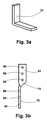
FIGS. 3 a-3 e show ceiling brackets according to aspects of the present invention; -
FIGS. 4 a and 4 b show end views of a ceiling according to aspects of the present invention; -
FIGS. 4 c and 4 d show details of a bullet proof plate according to the present invention; -
FIG. 5 shows a side view of a ceiling according to aspects of the present invention; -
FIG. 6 a shows a side view of another ceiling according to the present invention; -
FIG. 6 b shows a side view of another ceiling according to the present invention; -
FIG. 7 shows a side view of yet another ceiling according to the present invention; -
FIGS. 8 a-8 f show end views of support members according to the present invention; -
FIG. 9 a shows a side view of a portion of a shoot house according to the present invention; -
FIG. 9 b shows a side view of a portion of a shoot house according to the present invention; -
FIG. 10 shows a front view of first and second floor walls according to the present invention; -
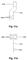
FIG. 11 a shows a front view of a bracket of the present invention; -
FIG. 11 b shows a side view of the bracket ofFIG. 11 a; -
FIG. 12 a shows a front view of a bracket of the present invention; -
FIG. 12 b shows a side view of the bracket ofFIG. 12 a; -
FIG. 13 shows a joint of a shoot house using the bracket ofFIGS. 11 a and 11 b; -
FIG. 14 shows a joint of a shoot house using the bracket ofFIGS. 12 a and 12 b; -
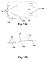
FIG. 15 a shows a top view of a bracket of the present invention; -
FIG. 15 b shows a side view of the bracket ofFIG. 15 a; -
FIG. 15 c shows an end view of the bracket ofFIG. 15 a; -
FIG. 16 a shows a side view of a bracket of the present invention; -
FIG. 16 b shows a top view of the bracket ofFIG. 16 a; -
FIG. 17 shows a joint of a shoot house using the bracket ofFIGS. 16 a and 16 b; and -
FIG. 18 shows a joint of a shoot house using the bracket ofFIGS. 15 a through 15 c. - It will be appreciated that the drawings are illustrative and not limiting of the scope of the invention which is defined by the appended claims. The various embodiments shown accomplish various aspects and objects of the invention. It is further appreciated that it is not possible to show each structure and element of the invention in a single drawing, and as such multiple drawings are presented which each show aspects of the invention in greater detail. The invention thus encompasses all of the drawings.
- The drawings will now be discussed in reference to the numerals provided therein so as to enable one skilled in the art to practice the present invention. The drawings and descriptions are exemplary of various aspects of the invention and are not intended to narrow the scope of the appended claims.
- Turning to
FIG. 1 , a section of a modular shoot house wall as known in the prior art is shown. Modular shoot houses have been formed with bullet proof steelplate wall panels joints 22 between theplates steel 26 and a facing strip ofsteel 30 which are bolted together to prevent bullets from passing through the joint. - Additionally, strips of
wood 34 may be attached to the steel wall, with sheets of sheetrock orplywood 38 attached to the wood strips 34, forming a space to contain bullets and also making the surface of the wall look more similar to a conventional wall. Typically, a simple roof, such as a layer of corrugated metal or a tent like canopy, is placed over the shoot house to protect the shoot house from rain or the like if the shoot house is used in a rainy environment. - As mentioned previously, two level shoot houses have been formed by constructing sufficient support pillars or load bearing walls to support a concrete ceiling and then forming a shoot house under the structure. The lower level of the shoot house is built underneath the concrete, and an upper level is built above the concrete. As previously discussed, the concrete ceiling and supports can not be moved, and often do not integrate well into the shoot house. For example, a support column may extend into a room or may partially obstruct a hall.
- Turning to
FIG. 2 , a wall of a shoot house according to the present invention is shown. The wall, indicated generally at 42, is formed of panels ofsteel strip 54 is placed over the joint. A backing member, such as a strip, washers, or the like (not shown), is placed across the back of the joint and the facing strip and backing member are bolted against the plates bybolts 58, clamping the facing strip and backing member against the plates and securely holding the wall together. - A
bracket 62 is also attached to thewall 42. Thebracket 62 may be attached withbolts 66, or it may be welded to the facing strip or otherwise attached to the facing strip, or formed integrally with the facing strip. Thebracket 62 is designed to support the ceiling of the shoot house as will be discussed in the following figures. As the various ceiling pieces are assembled on top of the walls, the ceiling pieces brace the walls and strengthen the structure. It will be appreciated that using a number ofbolts 66 not only strengthens the attachment between thewall 42 and thebracket 62, but also provides some flexibility in mounting the bracket. In addition tobolts 66, the bracket may simply be welded or otherwise attached to the facingstrip 54 if so desired. For example, facing strips made for a multi-level shoot house may be constructed with brackets permanently attached, as nearly all facing strips can be used to support the ceiling structure. Likewise, the brackets can be formed integrally with the facing strips. It is appreciated that the wall shows inFIG. 2 may also include spacing strips such as wood strips disposed along and/or attached to the facing strips, and plywood sheet or other sheet attached to the spacing strip to form a bullet containment chamber similar to that ofFIG. 1 . - The structures shown and discussed relative to
FIG. 2 are also encompassed in the other figures, asFIG. 2 shows only a portion of the invention. - Turning to
FIG. 3 a throughFIG. 3 e, various brackets according to the present invention are shown.FIG. 3 a shows abracket 70 which is simply an L shaped bracket formed form a piece of steel. It will be appreciated that the bracket must both attach to the wall and support the ceiling, and that an L bracket provides the necessary surfaces. The bracket may be welded or otherwise attached to the walls and ceiling. Additionally, the bracket may be bolted to the walls and ceiling. In one embodiment, the bracket is bolted to the wall facing strips and the ceiling support members so that the facing strips form support columns integral to the shoot house. This leaves maximum flexibility in constructing a modular shoot house. Accordingly, the bracket may be provided with holes formed in the bracket for receiving such bolts. -
FIG. 3 b shows anotherbracket 74 which has been formed from a strip of steel which is twisted such that oneend 78 may attach to the wall and theother end 82 may be attached to the side of a ceiling rail or support. Also, holes 86 have been formed in thebracket 74 so that the bracket may be easily attached to the wall and ceiling. As many holes as are necessary may be formed in the bracket. It will be appreciated that the bracket may be made sufficiently large to be strong enough to support the weight which will be placed on it. One of skill in the art will recognize that the bracket must be sufficiently large so as not to bend or otherwise deform under the weight of the ceiling. Additionally, the attachment means, such as the bolts, must be sufficiently strong to support the weight of the ceiling and any other shoot house structure on top of the ceiling. This may mean that a particular number of bolts must be used, depending on the shear strength of the bolts. -
FIG. 3 c shows another bracket according to the present invention. Thebracket 90 has been formed from steel, and has anupper portion 94 which is attached to the wall. Thelower portion 98 attaches to the ceiling members, and has twoside arms lower portion 98 has been shaped to support a beam or channel which supports the ceiling panels. With the part of the bracket which attaches to thewall 94 being bent up above the part of the bracket which supports theceiling 98, theupper portion 94 is protected from bullets by the ceiling. It will be appreciated that many different means may be used to attach the bracket to the wall and ceiling, with welding and bolting being the most common methods. In one embodiment, the bracket will be formed with holes similar to the brackets inFIGS. 3 b and 3 d, and that the various shoot house components such as the facing strips and ceiling support members will have corresponding holes formed therein to facilitate construction of the shoot house. -
FIG. 3 d shows abracket 110 which is similar to the bracket ofFIG. 3 , except that thelower portion 114 is configured for attachment to a wall, and theupper portion 118 is shaped to support the ceiling. The upper portion has twotabs bracket 110 is shown withholes 130 to attach the bracket to the wall and ceiling. Asmany holes 130 as are needed may be formed so long as thebracket 110 is not weakened by the holes. It will be appreciated that while thelower portion 114 is more exposed to bullets than theupper portion 94 of the bracket ofFIG. 3 c, thebracket 110 ofFIG. 3 d may be easier to install. -
FIG. 3 e shows anotherbracket 134 according to the present invention. Thebracket 134 may be formed from an L shaped piece of metal which has been bent twice into the shape shown. Thebracket 134 is thus simple to form. Alower portion 138 is provided to attach the bracket to a wall, and anupper portion 142 is attached to the ceiling members. Atab 146 is bent as shown to further support the ceiling members.Holes 150 have been formed in theupper portion 142 of thebracket 134 to allow the ceiling members to be bolted to the bracket. Additionally, a number ofholes 154 have been formed in thelower portion 138 of thebracket 134 for attachment to the walls of a shoot house. Having a number ofholes 154 may allow the height of thebracket 134 relative to the wall to be adjusted if so desired, ensuring that the floor is level and in the correct position. Having a number of holes will also allow more bolts to be used to attach the bracket to the wall, providing a more secure attachment to the walls of the shoot house. - It is appreciated from
FIGS. 3 a-3 e that many different bracket shapes and configurations are available which are suitable for attaching a ceiling member (typically a support beam type member) to a modular ballistic wall. The brackets ofFIGS. 3 a-3 e are thus part ofFIGS. 9 a and 9 b, and of the other figures. Many of the figures show only subassemblies or portions of the invention and are thus viewed in combination with the other figures to appreciate the entire invention. - Turning to
FIG. 4 a, an end view of a ceiling of the present invention is shown. The ceiling may be formed of standardsized steel plates 158. Typically, theedges 162 of theplates 158 are placed adjacent one another forming a joint. The joint is covered with a facingstrip 166 and a backing means or backingmember 170, which may be a backing strip, a number of washers, or the like. The facingstrip 166 andbacking member 170 may be held together by an attachment means such asbolts 174 andnuts 178 which may extend between or through the plates. Alternative methods of fastening are available, such as threading the backing member, using rivets or screws or the like, but a nut and bolt are the most convenient. - The steel plate may be supported by various support members, such as
channels 182. The support members may be sized and spaced according to the strength needed in the ceiling. The support members may typically be attached to the brackets which are attached to the walls. They will then serve to both support and strengthen the ceiling and brace the walls. It will be appreciated that many different shapes of support members may be used, including members with cross sections such as channels, boxes, I beams, C beams, etc. Additionally, many methods of attaching thesteel plate 158 to thesupport members 182, such as welding, bolting, gluing, etc. The more preferred method of attaching the plate to the support members is bolting, as it leaves maximum flexibility in constructing and modifying the shoot house. - Turning now to
FIG. 4 b, another side view of a ceiling of the present invention is shown. The ceiling shown is similar to the ceiling ofFIG. 4 a, and is a functional equivalent of the ceiling ofFIG. 4 a. The ceiling includessteel plates 158 which are placed adjacent each other and joined with a facingstrip 166 and backing means 170, which may be a backing strip, washers, etc. Theedges 162 of thesteel plates 158 haveopenings 164 formed therein to allow thebolts 174 to pass through theplates 158 to assemble the joint. It is appreciated that various methods of forming the joint are possible, including passing thebolts 174 between the plates or through the plates. What is important is forming a joint which is not easily penetrated by bullets, as is accomplished by securely fastening the facingstrip 166 to theedges 162 of theplates 158. - Turning now to
FIG. 4 c, a perspective view of a part of a plate as may be used in forming walls or ceilings is shown. Theplate 158 includes anopening 164 which a bolt may pass through. In theplate 158 shown, theopening 164 is a hole.FIG. 4 d shows a similar portion of aplate 158 where theopening 164 is formed as a keyhole slot. Such a keyhole slot may be more easily formed by a plasma cutter, or other methods. It is thus appreciated that it is not critical precisely how a hole may be formed. Any of the joints between plates shown in the present invention may be formed as shown inFIGS. 4 a-4 d. For clarity, not every possible type of joint is shown with every possible wall or ceiling structure, or in combination with every possible shape of support beam. - Turning to
FIG. 5 , another side view of a ceiling is shown. The ceiling is formed withsteel plates support members upper edge members joints member support bolts nuts - It will be appreciated that a ceiling such as that of
FIG. 5 may be assembled by attaching thesupport members steel panels - If necessary, additional support members may be placed between the joints to stiffen the ceiling and prevent the steel plate from bending under the weight which may be placed upon it. Such support member may be similar to the
supports support members - In addition to ease of assembly, the ceiling may be assembled in a variety of configurations. If the ceiling is assembled with standard sized steel panels, each panel may be placed in any location in the ceiling whereas specially shaped panels must be placed in particular locations in a ceiling. Additionally, the steel panels used may be the same size as the walls of the shoot house. For example, if four foot by eight foot panels are used, the walls of the first level of the shoot house would form joints which are spaced apart every four feet and walls would be spaced apart in four foot increments. All of the joints would be evenly spaced in four foot increments.
- Accordingly, ceiling plates which are also four foot by eight foot panels would align with the wall panels such that the ceiling joints and edges would align with the joints of the wall panels. Thus, it is easy to locate the support members and construct the ceiling. Accordingly, support members may be placed in a parallel arrangement between the joints of the wall panels, stretching across the shoot house, and the ceiling panels would line up properly on the support members. Additionally, the support members would only need be provided in four foot increments, and the maximum length of the members needed would be determined by the width of the rooms. Many configurations of shoot houses could be built by having four, eight, and twelve foot support members. If the members all stretch the same direction across the shoot house, rooms with a side longer than twelve feet such as hallways may be oriented perpendicular to the support members.
- Turning to
FIG. 6 a, a side view of another ceiling according to the present invention is shown. The ceiling has been formed from a number ofsteel plates strips bolts nuts plates strips support members panels floor panels floor sheeting strips bolts - Additionally, sheets of a second material have been attached to the ceiling. The
sheets support members bolts 310 andnuts 314, or by screws or any other suitable attachment method. Thesheets bullet containment area 318 in the ceiling to prevent bullets from striking the ceiling and ricocheting back towards people in the shoot house. Thus, plywood may be an ideal sheeting material as it is not overly damaged by a bullet and is strong enough to prevent bullets from exiting the containment area. Additionally, the floor sheeting may make the floor less slippery when wet. - Turning now to
FIG. 6 b, another side view of a ceiling according to the present invention is shown. The ceiling is similar to the ceiling ofFIG. 6 a, but includes additional floor support structure. The structure ofFIG. 6 b includesbrackets 264 which may be formed as part of or simply attached to the facingstrips brackets 264 may be used to attachsupport rails 268, such as 2×4 lumber, which are used to support thefloor panels support members support members - Turning now to
FIG. 7 , an end view of another ceiling according to the present invention. The ceiling, indicated generally at 322, is formed with a plurality ofsteel panels joints support members support members backing strips bolts FIG. 7 and a second floor is to be built above the ceiling,sheet material 370, such as plywood, may be placed on top of thesupport members sheet material 370 may be replaced by a roofing material of choice, or whatever material is necessary and suitable. - The strips and support members cover the joint between the panels and make it very unlikely that a bullet striking the joint would be able to pass through the joint. It will be appreciated from this figure that a large number of different ceiling configurations are possible with the present ceiling. As shown, the steel plates may be suspended from the support members. Additionally, the support members may have a variety of different shapes. In a preferred embodiment, the shapes may have a flat side for attachment to the steel panels.
- Turning now to
FIGS. 8 a-8 f, a number of different shapes for support members are shown. The shapes shown are support member shapes according to a more preferred embodiment, and do not represent all of the shapes of support members which are suitable for use in the invention. The shapes include abox section 374, aC section 378, anL section 382, anI beam 386, and two channel shapedmembers flat surface - A shoot house which is formed according to the present invention should be sufficiently rigid and strong for most applications. While an open framework of facing strips and ceiling support members may be moved somewhat with relative ease, that same framework is quite stiff with the steel plate panels attached thereto. The steel plates prevent motion of the framework. As the shoot house is built by adding steel plates and either facing strips or ceiling support members in close succession, it is naturally rigid as it is being constructed. It is not, however, beyond the scope of the invention to use bracing members to further strengthen a shoot house where the size or particular configuration necessitates such bracing strips.
- The bracing strips primarily prevent the shoot house from swaying side to side, front to back, or from twisting, as may be caused by wind, weather, moving objects within a shoot house, etc. Accordingly, the bracing strips may simply be strips of steel which attach to existing joints within the shoot house, such as facing strips, backing means, ceiling support members, etc. The bracing strips would typically be placed so as to connect two pieces, such as facing strips or ceiling support members, with the bracing strip being at an angle, preferably a 45 degree angle or close thereto, relative to the facing strips or support member. The bracing strip, when placed at an angle relative to the facing strip or support member, substantially inhibits movement of the facing strip or support member.
- According to the present invention, multi-story shoot houses may be formed. A shoot house may be formed which has a modular ceiling attached at or near the top of the walls. As discussed, the ceiling members will substantially stiffen the shoot house and inhibit movement of the shoot house. A second story or shoot house level may be constructed on top of the ceiling. Accordingly, the ceiling members may form part of or support for a floor for the second level. The walls for the second level may be attached to the upper portion of the first level walls, or may be attached to ceiling joints. It will be appreciated that if a modular shoot house is formed with each wall panel being a consistent width, such as four feet, the ceiling panels are also in four foot increments and joints may be found every four feet. Thus, virtually any configuration is possible for the second floor of the shoot house as joints between wall and ceiling panels occur every four feet, in each possible location for joints between wall panels for the second floor.
- Turning to
FIG. 9 a, a side view of a multi story shoot house is shown. A lower level wall has been formed with bulletproof wall panels 450, abacking strip 454 and facingstrip 458 placed to cover the joint between adjacent wall panels, andbolts 462 placed to hold the facing strip, backing strip, and panels firmly together. Abracket 466 has been attached to the wall via facingstrip 458 withbolts 470. It will be appreciated, however, that thebracket 466 may simply be welded to the facingstrip 458, or may be formed integral to the facing strip. Asupport member 474 is attached to thebracket 466 and used to supportceiling panels 478 in a manner similar to that shown inFIG. 6 . Abacking strip 482 may be used to cover joints between ceiling panels if necessary. The ceiling panels have been bolted 486 to thesupport member 474. As shown, the ceiling forms a floor for a second level of a shoot house. - A
bracket 490 has been attached to the ceiling withbolts 494, and used to support a second floor wall. The wall has been formed with bulletproof panels 498, a facingstrip 502, and abacking strip 506 held together withbolts 510. The wall is attached to thebracket 490 via the facingstrip 502 and is secured withbolts 514. Additionally, a plate orstrip 518 may be attached to the walls and used to support the upper level wall alone or in combination with abracket 490. Asecond bracket 522 has been attached to the ceiling via thebacking strip 482, and has been bolted 526 to thesupport member 474. Thebracket 522 has been used to attach a wall to the ceiling where there is not a lower level wall. The wall is formed with bulletproof panels 530, a facingstrip 534, and abacking strip 538, and the facing strip and backing strip are held to the panels withbolts 542. The wall is bolted 546 to thebracket 522 via the facingstrip 534. - Turning to
FIG. 9 b, a side view of a shoot house of the present invention is shown. The shoot house is similar to that ofFIG. 9 a and is numbered accordingly. One difference is that aspace 516 has been formed between the lower wall (includingsteel plate 450, backingstrip 454, and facing strip 458) and the ceiling (including thepanels 478 and backing strips 482). Thespace 516 may be used to route electrical cables, target control cables, etc. between adjacent rooms of the shoot house. Such a space may also be used for ventilation in the shoot house if desired. - A strip or
plate 518 may be used to bridge between the lower wall (includingsteel plate 450, backingstrip 454, and facing strip 458) and the ceiling (including thepanels 478 and backing strips 482) or an upper wall (includingsteel plates 498, facingstrips 502, and backing strips 506). Aplate 518 may be used which partially, substantially, or completely closes thespace 516, or a strip may be used to provide a stronger joint. Thus, the shoot house may be formed withspaces 516 which are then closed if desired withplates 516 after installation of all necessary wires, control cables, etc. Substantially closing thespace 516 would aid in containing bullets which might otherwise pass through the opening and exit the shoot house. It is appreciated that the areas adjacent the ceiling and floor of a shoot house often may pose increased risk of bullets passing around the ballistic walls, and often “no shoot zones” are designated for these areas. - While omitted for clarity, the walls and ceiling shown in
FIGS. 9 a and 9 b may also be covered with a sheeting material similar to the wall ofFIG. 1 and the ceiling ofFIG. 6 . The sheeting material is preferably a material which is penetrable by bullets but sufficiently durable to not be rapidly be broken down by the bullets. The sheeting material also should be sufficiently durable to not allow a bullet which has passed through the sheeting and ricocheted off of the bullet proof panel to again pass through the sheeting and exit the wall. It is also preferable to space the sheeting apart from the bullet proof panels. The sheeting would thus form a bullet containment area and would make the shoot house significantly safer by substantially eliminating the risk of being hit by a ricocheting bullet. Plywood has been found to be an optimal material for covering the walls and ceiling. Sheeting material may also be placed on top of the ceiling to make a smoother floor for the second shoot house level. The sheeting may cover any backing strips, bolts, or the like which protrude from the ceiling. - It is appreciated that
FIG. 9 a andFIG. 9 b show assembled portions of a shoot house according to the present invention. It is not possible to show each of the structures without making these drawings confusing. Accordingly, wall joints, brackets, bullet containment chambers, etc. have been omitted for clarity in showing the assembled structure. As such, it is appreciated thatFIGS. 9 a and 9 b encompass and include the attachment details ofFIG. 2 , the brackets ofFIGS. 3 a through 3 e, the joint details shown inFIGS. 4 a, 4 b, 5, 6 a, 6 b, and 7, the plate details shown inFIGS. 4 c and 4 d, the bullet containment structures and floor structures ofFIGS. 6 a, 6 b, and 7, the beams ofFIGS. 8 a-8 f, and the joint details ofFIG. 10 . These structures are all shown individually for clarity in discussing the various substructures of the invention, but are all part of the whole invention embodied in a modular shoot house, as detailed inFIGS. 9 a and 9 b. -
FIGS. 9 a and 9 b show, in cross section, the general joint structure of a modular shoot house according to the present invention. It is appreciated that the specific shape and configuration of the brackets, joiner strips, pieces or plates, etc. may vary according to the use of the joint in the shoot house structure. Thus, different brackets and different resulting joint structures may be necessary where a ceiling support member is parallel to or perpendicular to a wall, or where the ceiling support member is placed above a wall or abutting into a wall. Thus,FIGS. 10 through 18 show details of the bracket shapes and resulting joint structures which accomplish various joints required in constructing a modular shoot house. As such, the joints and structures shown inFIGS. 10 through 18 are considered as part ofFIGS. 9 a and 9 b, being variations of the joint structures based on particular location or application within the resulting shoot house. - Turning now to
FIG. 10 , a front view of upper and lower bullet proof walls as used in a modular shoot house of to the present invention is shown. A lower wall has been formed with bulletproof panels 550 and facingstrips 554 covering the joints betweenpanels 550. An upper wall has been similarly formed with bulletproof panels 558 and facing strips 562. It will be appreciated that often a joint 566 will exist betweenupper wall panels 558 andlower wall panels 550. To further strengthen the shoot house, the joint 566 may be covered with a facingstrip 570 which is attached to thewall panels bolts 574. A backing means such as a backing strip, washer, or the like, may be placed on the opposite side of the joint 566 and held to the joint with thebolts 574. Alternatively, the joint 566 may be strengthened by smallerjoint plates 578 which are attached to thewall panels bolts 582. Additionally, the joint 566 may simply be strengthened by a plurality ofbolts 586 andwashers 590, having washers and nuts placed on the opposite side of the joint 566. As the joint 566 will typically be covered by the lower level ceiling/upper level floor or will be very near the floor in an area unlikely to be struck by a bullet, it may not be necessary to cover the entire joint 566 with ajoint strip 570. It may, however, be desirable to use a simple fastener such asbolts 586 andwashers 590 to further attach theupper panels 558 to thelower panels 550 and thereby brace the panels. - It will be appreciated that in building a shoot house according to the present invention, it is desirable to cover the joints between wall and ceiling panels with a continuous strip of metal. Thus, facing strips have been shown covering the wall joints and ceiling joints. It is also possible to cover the ceiling joints with a flat surface of a support member, as has been shown. Once the joint has been covered by a metal strip, it is not necessary, though it is desirable, to cover the side of the joint opposite the facing strip or support member with a continuous metal strip. Washers or other similarly sized objects are sufficient to secure the bolts and facing strips to the joints, providing an increased support surface for attaching the bolts. Backing means may not be necessary in all situations. It will also be appreciated that whenever bolts are used in this application to fasten objects together, the bolts may be inserted into threaded holes in the appropriate location, or may simply be attached and tightened with nuts. Screws, rivets, welding, or other fastening methods are also equally applicable and within the scope of the invention.
- Turning now to
FIG. 11 a a front view of a bracket of the present invention is shown. Thebracket 610 is configured to attach a horizontal support member as may be used in a ceiling to a shoot house wall. The bracket therefore hasholes 614 formed therein for attachment to the wall, such as by bolting to the facing strip or to the joint between wall plates. Thebracket 610 also includes aflange 618 which is disposed perpendicular to the body of the bracket and which is used to attach the ceiling support member to the bracket. -
FIG. 11 b shows a side view of the bracket ofFIG. 11 a. The side view of thebracket 610 more clearly shows theflange 618 and theholes 622 formed in the flange which are used to bolt or otherwise attach the bracket to the ceiling support member. It will be appreciated that theflange 618 may be formed integrally to the bracket, such as by bending a flat plate into a bracket with perpendicular flange. Alternatively, the flange may be a separate plate which is welded or otherwise attached to the bracket. - Turning now to
FIG. 12 a, a front view of another bracket of the present invention is shown. Thebracket 626 is configured to attach a ceiling support member to a wall where the support member is parallel to the wall. As such, the bracket has afirst flange 630 which is attached to the wall and asecond flange 634 which is attached to the support member. -
FIG. 12 b more clearly shows thefirst flange 630 andsecond flange 634. It is again appreciated that thefirst flange 630 andsecond flange 634 may be formed as part of thebracket 626, such as being cut from flat sheet and bent into place, or may be welded or attached to the bracket.Holes 638 are formed in thefirst flange 630 and used to attach the flange to the wall, such as by attachment to a facing strip or to the joint. Similarly, holes may be formed in thesecond flange 634 and used to attach the bracket to the ceiling support member. - Turning now to
FIG. 13 , a joint of a shoot house incorporating the bracket ofFIGS. 11 a and 11 b is shown. Thebracket 610 is attached, withfasteners 654 such as bolts, to a joint (indicated generally at 650) formed between twoplates strip 658 as has been discussed. For clarity, many of the structures such as facing or backing strips, bolts, bullet containment chambers, sheeting, flooring, etc. are removed from the joints shown inFIGS. 13, 14 , 17, and 18. The joints are shown without such structures to allow for greater clarity in viewing the brackets and methods of attaching wall panels and joints to ceiling support members and ceiling panels. The ceiling panels may not be shown, but are attached according to the methods shown. - The
bracket 610 is typically bolted to aceiling support member 662 viaflange 618. Theceiling support member 662 is used to support the ceiling structure, shown generally at 666. Theceiling structure 666 is as has been discussed and may include ballistic panels and joints, as well as support rails and flooring sheets such as plywood or subflooring. Another wall section (indicated at 670) may be attached to theceiling structure 666 as has been shown, such as inFIG. 9 a. - Turning now to
FIG. 14 , a joint of a shoot house of the present invention is shown. The joint utilizes the bracket ofFIGS. 12 a and 12 b. As has been discussed, thebracket 626 is configured for mounting aceiling support member 678 parallel to awall 682. Thewall 682 is formed withsteel panels 686 joined with a facingstrip 690 as has been discussed. Thebracket 626 is attached to thewall 682 by bolting thefirst flange 630 to the joint, and to theceiling support member 678 by bolting thesecond flange 634 to the ceiling support member. A ceiling/floor 694 may be attached to theceiling support member 678, and may possibly include bullet proof panels, bullet containment chambers, floor beams and sheeting, etc. as has been discussed. Anupper wall 698 may be attached to theceiling support member 678 or to the floor/ceiling 694 as has been previously shown and discussed, such as inFIG. 9 a or 9 b. - Turning now to
FIG. 15 a, a top view of another bracket of the present invention is shown. Thebracket 706 is configured for attaching a support member such as the ceiling support members discussed to a wall where the support member is perpendicular to the wall and extends from a wall rather than being disposed above the wall. Thebracket 706 includes afirst flange 710 havingholes 714 which is configured for attachment to a wall, such as by bolting to a joint between wall panels. Thebracket 706 also includes asecond flange 718 havingholes 722 which is configured for attachment to a support member. -
FIG. 15 b shows a side view of the bracket ofFIG. 15 a, better illustrating thesecond flange 718 and holes 722.FIG. 15 c shows an end view of the bracket ofFIG. 15 a, and better illustrates thefirst flange 710 and holes 714. In discussing this and all other brackets, it is appreciated that the number and location of holes as well as the configuration of the bracket may be adjusted according to the mounting location of the bracket, weight carried by the bracket, etc. - Turning now to
FIG. 16 a, a side view of a bracket of the present invention is shown. Thenbracket 730 is configured for attaching a support member to a wall where the support member is generally parallel to the wall and extends from the wall instead of being above the wall. Thebracket 730 has afirst flange 734 havingholes 738 which attaches to a wall, such as to a joint or facing strip. The bracket also has asecond flange 742 withholes 746 which may be attached to a support member. As can more clearly be seen inFIG. 16 b, thebracket 730 may have acenter section 750 which connects thefirst flange 734 andsecond flange 742 in a zigzag shape. Such acenter flange 750 offsets thefirst flange 734 andsecond flange 742 from each other, allowing for easier attachment of the bracket to both a wall and support member. - Turning now to
FIG. 17 , a joint of a shoot house incorporating the bracket ofFIGS. 16 a and 16 b is shown. Thebracket 730 is shown attaching asupport member 758 to a wall joint, indicated at 762. The wall structure and joint 762 are formed as has been shown and discussed previously. It will be appreciated that aspace 766 may formed between theplates 770 adjacent thebracket 730 andsupport member 758, or no space may be present. Attaching a support member parallel to a wall as shown may allow for the installation of stairs, etc. in the shoot house. - Turning now to
FIG. 18 , a joint of a shoot house using the bracket ofFIGS. 15 a through 15 c is shown. Thebracket 706 has been used to attach asupport member 778 to a wall. Thesupport member 778 extends perpendicularly from the wall. The wall includessteel panels 782 joined by a facingstrip 786 as has been previously discussed. Thebracket 706 has been bolted to the joint, but may be welded or otherwise attached. - It is appreciated that the various structures and assemblies of the shoot house which have been discussed are each small parts of the invention, which may require a combination of these structures to form a completed shoot house. Various structures of the shoot house, such as ceilings, floors, stairs, etc. will each require different types of brackets, or combinations of the brackets and joints shown.
- There is thus disclosed an improved method for forming shoot houses. It will be appreciated that numerous modifications may be made to the present invention without departing from the scope of the invention. The preceding examples are illustrative of the invention, and do not define the scope of the invention.
Claims (61)
Priority Applications (1)
| Application Number | Priority Date | Filing Date | Title |
|---|---|---|---|
| US11/397,940 US20060234069A1 (en) | 2005-04-05 | 2006-04-03 | Method for forming shoot houses |
Applications Claiming Priority (2)
| Application Number | Priority Date | Filing Date | Title |
|---|---|---|---|
| US66870805P | 2005-04-05 | 2005-04-05 | |
| US11/397,940 US20060234069A1 (en) | 2005-04-05 | 2006-04-03 | Method for forming shoot houses |
Publications (1)
| Publication Number | Publication Date |
|---|---|
| US20060234069A1 true US20060234069A1 (en) | 2006-10-19 |
Family
ID=37108833
Family Applications (1)
| Application Number | Title | Priority Date | Filing Date |
|---|---|---|---|
| US11/397,940 Abandoned US20060234069A1 (en) | 2005-04-05 | 2006-04-03 | Method for forming shoot houses |
Country Status (1)
| Country | Link |
|---|---|
| US (1) | US20060234069A1 (en) |
Cited By (33)
| Publication number | Priority date | Publication date | Assignee | Title |
|---|---|---|---|---|
| US20050022658A1 (en) * | 2002-07-12 | 2005-02-03 | Kyle Bateman | Modular ballistic wall |
| US20060115796A1 (en) * | 2003-02-19 | 2006-06-01 | Fred Riermann | Modular assault course |
| US20060240391A1 (en) * | 2004-12-30 | 2006-10-26 | Addison Sovine | Training door |
| US20070040334A1 (en) * | 2005-08-19 | 2007-02-22 | Thomas Marshall | Target clamping system |
| US20070102883A1 (en) * | 2002-09-17 | 2007-05-10 | Action Target, Inc. | Projectile retrieval system |
| US20070210522A1 (en) * | 2004-10-01 | 2007-09-13 | Halverson Michael D | Modular shooting range |
| US20070235943A1 (en) * | 2006-03-31 | 2007-10-11 | Kyle Bateman | Drop target |
| US20080235565A1 (en) * | 2007-03-21 | 2008-09-25 | International Business Machines Corporation | System and Method for Reference Validation in Word Processor Documents |
| US7497441B2 (en) | 2005-09-08 | 2009-03-03 | Action Target, Inc. | Adjustable target mount |
| US7653979B2 (en) | 2001-12-12 | 2010-02-02 | Action Target Inc. | Method for forming ballistic joints |
| GB2464450A (en) * | 2008-10-08 | 2010-04-21 | Nigel Rust | Modular adaptable shooting range |
| US20100175333A1 (en) * | 2009-01-14 | 2010-07-15 | Fred Riermann | Shoothouse cleanouts |
| US7775526B1 (en) | 2001-12-12 | 2010-08-17 | Action Target Inc. | Bullet trap |
| US7967296B1 (en) | 2006-03-14 | 2011-06-28 | Sri Aquisition Corp. | Modular shooting system |
| US8016291B2 (en) | 2005-08-19 | 2011-09-13 | Action Target Inc. | Multifunction target actuator |
| US20110219725A1 (en) * | 2008-05-30 | 2011-09-15 | Smith Jeffery L | Ballistic and Forced Entry Resistant Construction |
| US8162319B2 (en) | 2007-11-07 | 2012-04-24 | Action Target Inc. | Method for advancing and retracting a target |
| US20120240754A1 (en) * | 2011-03-22 | 2012-09-27 | William James | Expended Cartridge Case Receiver |
| US8469364B2 (en) | 2006-05-08 | 2013-06-25 | Action Target Inc. | Movable bullet trap |
| US8579294B2 (en) | 2010-12-21 | 2013-11-12 | Action Target Inc. | Emergency stopping system for track mounted movable bullet targets and target trolleys |
| US8684361B2 (en) | 2011-01-17 | 2014-04-01 | Action Target Inc. | Target system |
| US8827273B2 (en) | 2010-08-02 | 2014-09-09 | Action Target Inc. | Clearing trap |
| US8875613B2 (en) * | 2012-05-08 | 2014-11-04 | Kerry O'Neal | Removable inspection panel |
| US9217623B2 (en) | 2013-03-25 | 2015-12-22 | Action Target Inc. | Bullet deflecting baffle system |
| US20160178329A1 (en) * | 2014-01-10 | 2016-06-23 | Mgm Holdings, Llc | Portable ballistic divider wall |
| US9482494B1 (en) * | 2015-06-11 | 2016-11-01 | Southern States, Llc | Bullet resistant shield for electric power equipment |
| US9784538B2 (en) | 2015-01-16 | 2017-10-10 | Action Target Inc. | High caliber target |
| US9927216B2 (en) | 2015-01-16 | 2018-03-27 | Action Target Inc. | Target system |
| CN108413813A (en) * | 2018-06-05 | 2018-08-17 | 福建泉城特种装备科技有限公司 | Shellproof unit and its manufacturing method and the pin-connected panel wall to impede bullets for having the shellproof unit |
| US10371489B2 (en) | 2016-01-15 | 2019-08-06 | Action Target Inc. | Bullet deceleration tray damping mechanism |
| US10876821B2 (en) | 2017-01-13 | 2020-12-29 | Action Target Inc. | Software and sensor system for controlling range equipment |
| EP3555486B1 (en) | 2016-12-19 | 2021-01-27 | NEXTER Systems | Anti-projectile protection device for an attachment means and inspection hatch implementing such a device |
| US11029134B2 (en) | 2018-01-06 | 2021-06-08 | Action Target Inc. | Target carrier system having advanced functionality |
Citations (88)
| Publication number | Priority date | Publication date | Assignee | Title |
|---|---|---|---|---|
| US867406A (en) * | 1906-12-26 | 1907-10-01 | Lewis T Pates | Rail-bond. |
| US980255A (en) * | 1910-04-04 | 1911-01-03 | Oscar W Herms | Greenhouse construction. |
| US1155717A (en) * | 1914-12-24 | 1915-10-05 | C C Fouts Company | Joint for metallic sheets. |
| US1724601A (en) * | 1924-09-08 | 1929-08-13 | Motor Products Corp | Molding |
| US1803514A (en) * | 1928-12-19 | 1931-05-05 | Robertson Co H H | Building construction |
| US1957933A (en) * | 1930-05-31 | 1934-05-08 | Brandl Lillian | Sheet metal joint |
| US2054665A (en) * | 1935-11-18 | 1936-09-15 | Michael J Tracy | Jail and prison construction |
| US2105784A (en) * | 1936-10-12 | 1938-01-18 | Paul C Hagberg | Window channel or the like |
| US2170637A (en) * | 1938-02-24 | 1939-08-22 | Union Steel Prod Co | Insulating wall panel |
| US2208010A (en) * | 1937-04-19 | 1940-07-16 | Horace G Whitmore | Portable and sectional building construction |
| US2209580A (en) * | 1939-10-19 | 1940-07-30 | Sargents Sons Corp C G | Wall structure |
| US2212982A (en) * | 1939-04-10 | 1940-08-27 | Stefco Steel Company | Insulated metal building construction |
| US2231528A (en) * | 1939-03-28 | 1941-02-11 | Albert J Daniels | Glazing construction |
| US2269490A (en) * | 1939-02-20 | 1942-01-13 | Edwin E Slick | Building construction |
| US2350827A (en) * | 1940-05-15 | 1944-06-06 | Saulnier Raymond | Method of assembly of tanks and the like |
| US2412242A (en) * | 1943-05-03 | 1946-12-10 | House Maurice Beaud & Fils | Dismountable barrack |
| US2855871A (en) * | 1953-04-06 | 1958-10-14 | Glen H Huntington | Metal roofings |
| US2927665A (en) * | 1955-02-07 | 1960-03-08 | Chicago Metal Mfg Co | Prefabricated sealed building construction |
| US2932860A (en) * | 1957-05-10 | 1960-04-19 | Robert M Barth | Dispensing apparatus and window mount therefor |
| US2934934A (en) * | 1957-06-06 | 1960-05-03 | Henry A Berliner | Construction panel |
| US3263385A (en) * | 1962-08-29 | 1966-08-02 | Olin Mathieson | Building structure with anchored panels |
| US3398496A (en) * | 1963-09-17 | 1968-08-27 | Daimler Benz Ag | Clamping connection |
| US3423891A (en) * | 1965-08-25 | 1969-01-28 | Certain Teed Prod Corp | Building structure with the means between spaced panels |
| US3485405A (en) * | 1968-07-05 | 1969-12-23 | Us Plywood Champ Papers Inc | Frame-structure for container |
| US3530633A (en) * | 1968-05-29 | 1970-09-29 | Elwin G Smith & Co Inc | Building panel |
| US3619437A (en) * | 1969-02-25 | 1971-11-09 | U F Chemical Corp | Method of charging a cavity with urea-formaldehyde foam insulating material |
| US3793796A (en) * | 1971-09-24 | 1974-02-26 | R Hughes | Modular building system |
| US3927500A (en) * | 1974-09-16 | 1975-12-23 | Oscar M Plumlee | Fire resistant paneling system |
| US3969855A (en) * | 1973-08-25 | 1976-07-20 | Mageba S.A. | Movable platform for parking one vehicle above another |
| US4028856A (en) * | 1976-01-26 | 1977-06-14 | Mallyclad Corporation | Cover wall construction |
| US4186535A (en) * | 1977-06-10 | 1980-02-05 | Verco Manufacturing, Inc. | Shear load resistant structure |
| US4195453A (en) * | 1977-11-09 | 1980-04-01 | Komendant August E | Modular, multi-floor building |
| US4269006A (en) * | 1977-11-30 | 1981-05-26 | Kenneth Larrow | House assembly with prefabricated elements |
| US4285173A (en) * | 1979-12-26 | 1981-08-25 | Multuloc Corporation | Building deck structure |
| US4509301A (en) * | 1982-04-23 | 1985-04-09 | Head Robert L | Modular shooting range |
| US4592175A (en) * | 1984-05-30 | 1986-06-03 | Werner Metal Industries, Inc. | Modular habitation structure |
| US4598631A (en) * | 1984-09-04 | 1986-07-08 | Everett Robert W | Indoor gun firing range enclosure |
| US4644708A (en) * | 1985-10-03 | 1987-02-24 | Constructions Metalliques Fillod | Prefabricated modular building element and a building comprising such elements |
| US4723749A (en) * | 1986-05-19 | 1988-02-09 | Erico International Corporation | Channel clip |
| US4856791A (en) * | 1988-09-01 | 1989-08-15 | Linatex Corporation Of America | Protective mat assembly and installation method therefor |
| US5088741A (en) * | 1988-05-10 | 1992-02-18 | Andrea Simonetti | Modular firing ground |
| US5127340A (en) * | 1990-07-13 | 1992-07-07 | Viking Metal Cabinet Company Inc. | Adjustable shelving system |
| US5163689A (en) * | 1991-03-20 | 1992-11-17 | Bateman Kyle E | Turning target support structure and system |
| US5167098A (en) * | 1991-02-22 | 1992-12-01 | The Will-Burt Company | Fire resistant modular building |
| US5400692A (en) * | 1994-03-01 | 1995-03-28 | Bateman; Kyle E. | Bullet stop and containment chamber |
| US5592789A (en) * | 1995-06-13 | 1997-01-14 | American Containment Systems, Inc. | Modular supporting structure |
| US5600084A (en) * | 1996-01-16 | 1997-02-04 | The United States Of America As Represented By The Secretary Of The Army | Armor panel fastener device |
| US5670734A (en) * | 1994-10-05 | 1997-09-23 | United Defense, L.P. | Modular armor mounting system |
| US5811718A (en) * | 1994-03-01 | 1998-09-22 | Bateman; Kyle E. | Bullet stop and containment chamber with airborne contaminant removal |
| US5822936A (en) * | 1993-01-25 | 1998-10-20 | Bateman; Kyle E. | Interconnect system for modularly fabricated bullet stops |
| US5887405A (en) * | 1994-09-22 | 1999-03-30 | Carranza-Aubry; Rene | Precast integral structure elements and procedure for the fast construction of buildings with such elements |
| US5893241A (en) * | 1998-01-05 | 1999-04-13 | Schroeder; Michael P. | Precast concrete target house |
| US5907930A (en) * | 1997-11-26 | 1999-06-01 | Ricco, Sr.; John A. | Shooting range |
| US6027120A (en) * | 1991-01-18 | 2000-02-22 | Caswell International Corporation | Granulate backstop assembly |
| US6286269B1 (en) * | 2000-04-03 | 2001-09-11 | G. Michael Marcum | Prefabricated shooting house |
| US6311980B1 (en) * | 1999-09-28 | 2001-11-06 | Action Target, Inc. | Projectile retrieval system |
| US6341708B1 (en) * | 1995-09-25 | 2002-01-29 | Alliedsignal Inc. | Blast resistant and blast directing assemblies |
| US6378870B1 (en) * | 1999-12-24 | 2002-04-30 | Action Target, Inc. | Apparatus and method for decelerating projectiles |
| US6412231B1 (en) * | 2000-11-17 | 2002-07-02 | Amir Palatin | Blast shelter |
| US6415557B1 (en) * | 1999-01-26 | 2002-07-09 | Mccalley Richard M. | Protective shelter |
| US6438906B1 (en) * | 2000-07-18 | 2002-08-27 | Paul Janssens-Lens | Safe room |
| US6484990B1 (en) * | 2000-08-10 | 2002-11-26 | Action Target | Target clamp |
| US6508043B1 (en) * | 2000-02-11 | 2003-01-21 | Art Bond | Building construction system and method |
| US6533280B1 (en) * | 2000-03-03 | 2003-03-18 | H. Addison Sovine | Bullet backstop assembly |
| US6588759B1 (en) * | 2000-07-18 | 2003-07-08 | Action Target, Inc. | Target baffle bracket |
| US6745538B1 (en) * | 1999-07-30 | 2004-06-08 | Casma S.P.A. | Mounting structure |
| US6776418B1 (en) * | 2001-06-21 | 2004-08-17 | Addison Sovine | Target |
| US6808178B1 (en) * | 2000-08-28 | 2004-10-26 | Action Target, Inc. | Clearing trap |
| US20050022658A1 (en) * | 2002-07-12 | 2005-02-03 | Kyle Bateman | Modular ballistic wall |
| US6994349B2 (en) * | 2002-03-08 | 2006-02-07 | Action Target, Inc. | Portable dueling tree |
| US6994348B2 (en) * | 2002-03-08 | 2006-02-07 | Action Target, Inc. | Dueling tree |
| US20060208425A1 (en) * | 2001-12-12 | 2006-09-21 | Action Target, Inc. | Bullet trap |
| US20060240388A1 (en) * | 2005-04-12 | 2006-10-26 | Thomas Marshall | Turn-swing target adapter |
| US20060240391A1 (en) * | 2004-12-30 | 2006-10-26 | Addison Sovine | Training door |
| US7140615B1 (en) * | 1999-09-28 | 2006-11-28 | Action Target, Inc. | Projectile retrieval system |
| US7175181B1 (en) * | 2004-06-17 | 2007-02-13 | Action Target, Inc. | Portable shooting target |
| US7178297B2 (en) * | 2002-06-18 | 2007-02-20 | Richard J Seavy | Structures incorporating interlocking wall modules |
| US20070040334A1 (en) * | 2005-08-19 | 2007-02-22 | Thomas Marshall | Target clamping system |
| US7184944B1 (en) * | 2004-02-20 | 2007-02-27 | Unisys Corporation | Apparatus and method for the simulation of a large main memory address space given limited resources |
| US20070045965A1 (en) * | 2005-08-31 | 2007-03-01 | Kyle Bateman | Folding target stand |
| US20070072537A1 (en) * | 2005-08-19 | 2007-03-29 | Kyle Bateman | Air diffuser |
| US20070102883A1 (en) * | 2002-09-17 | 2007-05-10 | Action Target, Inc. | Projectile retrieval system |
| US20070113487A1 (en) * | 2005-11-21 | 2007-05-24 | Amec Earth & Environmental, Inc. | Re-configurable armored tactical personnel and collective training facility |
| US20070114724A1 (en) * | 2005-08-30 | 2007-05-24 | David Bassett | Modular ballistic wall and target system |
| US7225717B2 (en) * | 2004-06-15 | 2007-06-05 | Square One Armoring Services Company | Vehicle armor system |
| US7234890B1 (en) * | 2000-08-28 | 2007-06-26 | Action Target, Inc. | Joint for bullet traps |
| US7246471B2 (en) * | 2003-02-19 | 2007-07-24 | Fred Riermann | Modular assault course |
| US20070235943A1 (en) * | 2006-03-31 | 2007-10-11 | Kyle Bateman | Drop target |
-
2006
- 2006-04-03 US US11/397,940 patent/US20060234069A1/en not_active Abandoned
Patent Citations (99)
| Publication number | Priority date | Publication date | Assignee | Title |
|---|---|---|---|---|
| US867406A (en) * | 1906-12-26 | 1907-10-01 | Lewis T Pates | Rail-bond. |
| US980255A (en) * | 1910-04-04 | 1911-01-03 | Oscar W Herms | Greenhouse construction. |
| US1155717A (en) * | 1914-12-24 | 1915-10-05 | C C Fouts Company | Joint for metallic sheets. |
| US1724601A (en) * | 1924-09-08 | 1929-08-13 | Motor Products Corp | Molding |
| US1803514A (en) * | 1928-12-19 | 1931-05-05 | Robertson Co H H | Building construction |
| US1957933A (en) * | 1930-05-31 | 1934-05-08 | Brandl Lillian | Sheet metal joint |
| US2054665A (en) * | 1935-11-18 | 1936-09-15 | Michael J Tracy | Jail and prison construction |
| US2105784A (en) * | 1936-10-12 | 1938-01-18 | Paul C Hagberg | Window channel or the like |
| US2208010A (en) * | 1937-04-19 | 1940-07-16 | Horace G Whitmore | Portable and sectional building construction |
| US2170637A (en) * | 1938-02-24 | 1939-08-22 | Union Steel Prod Co | Insulating wall panel |
| US2269490A (en) * | 1939-02-20 | 1942-01-13 | Edwin E Slick | Building construction |
| US2231528A (en) * | 1939-03-28 | 1941-02-11 | Albert J Daniels | Glazing construction |
| US2212982A (en) * | 1939-04-10 | 1940-08-27 | Stefco Steel Company | Insulated metal building construction |
| US2209580A (en) * | 1939-10-19 | 1940-07-30 | Sargents Sons Corp C G | Wall structure |
| US2350827A (en) * | 1940-05-15 | 1944-06-06 | Saulnier Raymond | Method of assembly of tanks and the like |
| US2412242A (en) * | 1943-05-03 | 1946-12-10 | House Maurice Beaud & Fils | Dismountable barrack |
| US2855871A (en) * | 1953-04-06 | 1958-10-14 | Glen H Huntington | Metal roofings |
| US2927665A (en) * | 1955-02-07 | 1960-03-08 | Chicago Metal Mfg Co | Prefabricated sealed building construction |
| US2932860A (en) * | 1957-05-10 | 1960-04-19 | Robert M Barth | Dispensing apparatus and window mount therefor |
| US2934934A (en) * | 1957-06-06 | 1960-05-03 | Henry A Berliner | Construction panel |
| US3263385A (en) * | 1962-08-29 | 1966-08-02 | Olin Mathieson | Building structure with anchored panels |
| US3398496A (en) * | 1963-09-17 | 1968-08-27 | Daimler Benz Ag | Clamping connection |
| US3423891A (en) * | 1965-08-25 | 1969-01-28 | Certain Teed Prod Corp | Building structure with the means between spaced panels |
| US3530633A (en) * | 1968-05-29 | 1970-09-29 | Elwin G Smith & Co Inc | Building panel |
| US3485405A (en) * | 1968-07-05 | 1969-12-23 | Us Plywood Champ Papers Inc | Frame-structure for container |
| US3619437A (en) * | 1969-02-25 | 1971-11-09 | U F Chemical Corp | Method of charging a cavity with urea-formaldehyde foam insulating material |
| US3793796A (en) * | 1971-09-24 | 1974-02-26 | R Hughes | Modular building system |
| US3969855A (en) * | 1973-08-25 | 1976-07-20 | Mageba S.A. | Movable platform for parking one vehicle above another |
| US3927500A (en) * | 1974-09-16 | 1975-12-23 | Oscar M Plumlee | Fire resistant paneling system |
| US4028856A (en) * | 1976-01-26 | 1977-06-14 | Mallyclad Corporation | Cover wall construction |
| US4186535A (en) * | 1977-06-10 | 1980-02-05 | Verco Manufacturing, Inc. | Shear load resistant structure |
| US4186535B1 (en) * | 1977-06-10 | 1984-11-20 | ||
| US4195453A (en) * | 1977-11-09 | 1980-04-01 | Komendant August E | Modular, multi-floor building |
| US4269006A (en) * | 1977-11-30 | 1981-05-26 | Kenneth Larrow | House assembly with prefabricated elements |
| US4285173A (en) * | 1979-12-26 | 1981-08-25 | Multuloc Corporation | Building deck structure |
| US4509301A (en) * | 1982-04-23 | 1985-04-09 | Head Robert L | Modular shooting range |
| US4592175A (en) * | 1984-05-30 | 1986-06-03 | Werner Metal Industries, Inc. | Modular habitation structure |
| US4598631A (en) * | 1984-09-04 | 1986-07-08 | Everett Robert W | Indoor gun firing range enclosure |
| US4644708A (en) * | 1985-10-03 | 1987-02-24 | Constructions Metalliques Fillod | Prefabricated modular building element and a building comprising such elements |
| US4723749A (en) * | 1986-05-19 | 1988-02-09 | Erico International Corporation | Channel clip |
| US5088741A (en) * | 1988-05-10 | 1992-02-18 | Andrea Simonetti | Modular firing ground |
| US4856791A (en) * | 1988-09-01 | 1989-08-15 | Linatex Corporation Of America | Protective mat assembly and installation method therefor |
| US5127340A (en) * | 1990-07-13 | 1992-07-07 | Viking Metal Cabinet Company Inc. | Adjustable shelving system |
| US6027120A (en) * | 1991-01-18 | 2000-02-22 | Caswell International Corporation | Granulate backstop assembly |
| US5167098A (en) * | 1991-02-22 | 1992-12-01 | The Will-Burt Company | Fire resistant modular building |
| US5163689A (en) * | 1991-03-20 | 1992-11-17 | Bateman Kyle E | Turning target support structure and system |
| US5822936A (en) * | 1993-01-25 | 1998-10-20 | Bateman; Kyle E. | Interconnect system for modularly fabricated bullet stops |
| US5400692A (en) * | 1994-03-01 | 1995-03-28 | Bateman; Kyle E. | Bullet stop and containment chamber |
| US5535662A (en) * | 1994-03-01 | 1996-07-16 | Bateman; Kyle E. | Bullet stop and containment chamber |
| US5811718A (en) * | 1994-03-01 | 1998-09-22 | Bateman; Kyle E. | Bullet stop and containment chamber with airborne contaminant removal |
| US5887405A (en) * | 1994-09-22 | 1999-03-30 | Carranza-Aubry; Rene | Precast integral structure elements and procedure for the fast construction of buildings with such elements |
| US5670734A (en) * | 1994-10-05 | 1997-09-23 | United Defense, L.P. | Modular armor mounting system |
| US5592789A (en) * | 1995-06-13 | 1997-01-14 | American Containment Systems, Inc. | Modular supporting structure |
| US6341708B1 (en) * | 1995-09-25 | 2002-01-29 | Alliedsignal Inc. | Blast resistant and blast directing assemblies |
| US5600084A (en) * | 1996-01-16 | 1997-02-04 | The United States Of America As Represented By The Secretary Of The Army | Armor panel fastener device |
| US5907930A (en) * | 1997-11-26 | 1999-06-01 | Ricco, Sr.; John A. | Shooting range |
| US5893241A (en) * | 1998-01-05 | 1999-04-13 | Schroeder; Michael P. | Precast concrete target house |
| US6415557B1 (en) * | 1999-01-26 | 2002-07-09 | Mccalley Richard M. | Protective shelter |
| US6745538B1 (en) * | 1999-07-30 | 2004-06-08 | Casma S.P.A. | Mounting structure |
| US6990780B2 (en) * | 1999-07-30 | 2006-01-31 | Casma S.P.A. | Mounting structure |
| US6311980B1 (en) * | 1999-09-28 | 2001-11-06 | Action Target, Inc. | Projectile retrieval system |
| US7140615B1 (en) * | 1999-09-28 | 2006-11-28 | Action Target, Inc. | Projectile retrieval system |
| US7264246B2 (en) * | 1999-09-28 | 2007-09-04 | Action Target, Inc. | Projectile retrieval system |
| US6378870B1 (en) * | 1999-12-24 | 2002-04-30 | Action Target, Inc. | Apparatus and method for decelerating projectiles |
| US6508043B1 (en) * | 2000-02-11 | 2003-01-21 | Art Bond | Building construction system and method |
| US6533280B1 (en) * | 2000-03-03 | 2003-03-18 | H. Addison Sovine | Bullet backstop assembly |
| US6286269B1 (en) * | 2000-04-03 | 2001-09-11 | G. Michael Marcum | Prefabricated shooting house |
| US6438906B1 (en) * | 2000-07-18 | 2002-08-27 | Paul Janssens-Lens | Safe room |
| US6588759B1 (en) * | 2000-07-18 | 2003-07-08 | Action Target, Inc. | Target baffle bracket |
| US6484990B1 (en) * | 2000-08-10 | 2002-11-26 | Action Target | Target clamp |
| US7322771B1 (en) * | 2000-08-28 | 2008-01-29 | Action Target, Inc. | Joint for bullet traps |
| US6808178B1 (en) * | 2000-08-28 | 2004-10-26 | Action Target, Inc. | Clearing trap |
| US7234890B1 (en) * | 2000-08-28 | 2007-06-26 | Action Target, Inc. | Joint for bullet traps |
| US6412231B1 (en) * | 2000-11-17 | 2002-07-02 | Amir Palatin | Blast shelter |
| US6776418B1 (en) * | 2001-06-21 | 2004-08-17 | Addison Sovine | Target |
| US7219897B2 (en) * | 2001-06-21 | 2007-05-22 | Action Target, Inc. | Target |
| US20060220319A1 (en) * | 2001-12-12 | 2006-10-05 | Action Target, Inc. | Bullet trap |
| US20070069472A1 (en) * | 2001-12-12 | 2007-03-29 | Spencer Lambert | Bullet containment trap |
| US20080022847A1 (en) * | 2001-12-12 | 2008-01-31 | Kyle Bateman | Ballistic Joint |
| US7275748B2 (en) * | 2001-12-12 | 2007-10-02 | Action Target, Inc. | Inlet channel for bullet traps |
| US7194944B2 (en) * | 2001-12-12 | 2007-03-27 | Action Target, Inc. | Bullet trap |
| US20060208425A1 (en) * | 2001-12-12 | 2006-09-21 | Action Target, Inc. | Bullet trap |
| US6994349B2 (en) * | 2002-03-08 | 2006-02-07 | Action Target, Inc. | Portable dueling tree |
| US6994348B2 (en) * | 2002-03-08 | 2006-02-07 | Action Target, Inc. | Dueling tree |
| US7178297B2 (en) * | 2002-06-18 | 2007-02-20 | Richard J Seavy | Structures incorporating interlocking wall modules |
| US20050022658A1 (en) * | 2002-07-12 | 2005-02-03 | Kyle Bateman | Modular ballistic wall |
| US20070102883A1 (en) * | 2002-09-17 | 2007-05-10 | Action Target, Inc. | Projectile retrieval system |
| US7246471B2 (en) * | 2003-02-19 | 2007-07-24 | Fred Riermann | Modular assault course |
| US7184944B1 (en) * | 2004-02-20 | 2007-02-27 | Unisys Corporation | Apparatus and method for the simulation of a large main memory address space given limited resources |
| US7225717B2 (en) * | 2004-06-15 | 2007-06-05 | Square One Armoring Services Company | Vehicle armor system |
| US7175181B1 (en) * | 2004-06-17 | 2007-02-13 | Action Target, Inc. | Portable shooting target |
| US20060240391A1 (en) * | 2004-12-30 | 2006-10-26 | Addison Sovine | Training door |
| US20060240388A1 (en) * | 2005-04-12 | 2006-10-26 | Thomas Marshall | Turn-swing target adapter |
| US20070072537A1 (en) * | 2005-08-19 | 2007-03-29 | Kyle Bateman | Air diffuser |
| US20070040334A1 (en) * | 2005-08-19 | 2007-02-22 | Thomas Marshall | Target clamping system |
| US20070114724A1 (en) * | 2005-08-30 | 2007-05-24 | David Bassett | Modular ballistic wall and target system |
| US20070045965A1 (en) * | 2005-08-31 | 2007-03-01 | Kyle Bateman | Folding target stand |
| US20070113487A1 (en) * | 2005-11-21 | 2007-05-24 | Amec Earth & Environmental, Inc. | Re-configurable armored tactical personnel and collective training facility |
| US20070235943A1 (en) * | 2006-03-31 | 2007-10-11 | Kyle Bateman | Drop target |
Cited By (52)
| Publication number | Priority date | Publication date | Assignee | Title |
|---|---|---|---|---|
| US7793937B2 (en) | 2001-12-12 | 2010-09-14 | Action Target Inc. | Bullet trap |
| US7775526B1 (en) | 2001-12-12 | 2010-08-17 | Action Target Inc. | Bullet trap |
| US8091896B2 (en) | 2001-12-12 | 2012-01-10 | Action Target Inc. | Bullet trap |
| US9228810B2 (en) | 2001-12-12 | 2016-01-05 | Action Target Inc. | Bullet trap |
| US8128094B2 (en) | 2001-12-12 | 2012-03-06 | Action Target Inc. | Bullet trap |
| US9759531B2 (en) | 2001-12-12 | 2017-09-12 | Action Target Inc. | Bullet trap |
| US10088283B2 (en) | 2001-12-12 | 2018-10-02 | Action Target Inc. | Bullet trap |
| US8276916B2 (en) | 2001-12-12 | 2012-10-02 | Action Target Inc. | Support for bullet traps |
| US7653979B2 (en) | 2001-12-12 | 2010-02-02 | Action Target Inc. | Method for forming ballistic joints |
| US8485529B2 (en) | 2001-12-12 | 2013-07-16 | Action Target Inc. | Bullet trap |
| US20050022658A1 (en) * | 2002-07-12 | 2005-02-03 | Kyle Bateman | Modular ballistic wall |
| US20070102883A1 (en) * | 2002-09-17 | 2007-05-10 | Action Target, Inc. | Projectile retrieval system |
| US7246471B2 (en) * | 2003-02-19 | 2007-07-24 | Fred Riermann | Modular assault course |
| US20060115796A1 (en) * | 2003-02-19 | 2006-06-01 | Fred Riermann | Modular assault course |
| US7909331B2 (en) | 2004-10-01 | 2011-03-22 | Sri Aquisition Corp. | Modular shooting range |
| US20080302026A1 (en) * | 2004-10-01 | 2008-12-11 | Sri Aquisition Corp. | Modular shooting range |
| US7357394B2 (en) | 2004-10-01 | 2008-04-15 | Sri Acquisition Corp. | Modular shooting range |
| US20070210522A1 (en) * | 2004-10-01 | 2007-09-13 | Halverson Michael D | Modular shooting range |
| US7789666B2 (en) | 2004-12-30 | 2010-09-07 | Action Target Inc. | Training door |
| US20060240391A1 (en) * | 2004-12-30 | 2006-10-26 | Addison Sovine | Training door |
| US7469903B2 (en) | 2005-08-19 | 2008-12-30 | Action Target Acquisition Corp. | Target clamping system |
| US8550465B2 (en) | 2005-08-19 | 2013-10-08 | Action Target Inc. | Multifunction target actuator |
| US8016291B2 (en) | 2005-08-19 | 2011-09-13 | Action Target Inc. | Multifunction target actuator |
| US20070040334A1 (en) * | 2005-08-19 | 2007-02-22 | Thomas Marshall | Target clamping system |
| US7497441B2 (en) | 2005-09-08 | 2009-03-03 | Action Target, Inc. | Adjustable target mount |
| US7967296B1 (en) | 2006-03-14 | 2011-06-28 | Sri Aquisition Corp. | Modular shooting system |
| US7556268B2 (en) | 2006-03-31 | 2009-07-07 | Action Target, Inc. | Drop target |
| US20070235943A1 (en) * | 2006-03-31 | 2007-10-11 | Kyle Bateman | Drop target |
| US8469364B2 (en) | 2006-05-08 | 2013-06-25 | Action Target Inc. | Movable bullet trap |
| US20080235565A1 (en) * | 2007-03-21 | 2008-09-25 | International Business Machines Corporation | System and Method for Reference Validation in Word Processor Documents |
| US8162319B2 (en) | 2007-11-07 | 2012-04-24 | Action Target Inc. | Method for advancing and retracting a target |
| US20110219725A1 (en) * | 2008-05-30 | 2011-09-15 | Smith Jeffery L | Ballistic and Forced Entry Resistant Construction |
| GB2464450A (en) * | 2008-10-08 | 2010-04-21 | Nigel Rust | Modular adaptable shooting range |
| US20100175333A1 (en) * | 2009-01-14 | 2010-07-15 | Fred Riermann | Shoothouse cleanouts |
| US8827273B2 (en) | 2010-08-02 | 2014-09-09 | Action Target Inc. | Clearing trap |
| US8579294B2 (en) | 2010-12-21 | 2013-11-12 | Action Target Inc. | Emergency stopping system for track mounted movable bullet targets and target trolleys |
| US8684361B2 (en) | 2011-01-17 | 2014-04-01 | Action Target Inc. | Target system |
| US20120240754A1 (en) * | 2011-03-22 | 2012-09-27 | William James | Expended Cartridge Case Receiver |
| US8875613B2 (en) * | 2012-05-08 | 2014-11-04 | Kerry O'Neal | Removable inspection panel |
| US9217623B2 (en) | 2013-03-25 | 2015-12-22 | Action Target Inc. | Bullet deflecting baffle system |
| US20160178329A1 (en) * | 2014-01-10 | 2016-06-23 | Mgm Holdings, Llc | Portable ballistic divider wall |
| US9784538B2 (en) | 2015-01-16 | 2017-10-10 | Action Target Inc. | High caliber target |
| US9927216B2 (en) | 2015-01-16 | 2018-03-27 | Action Target Inc. | Target system |
| US10168128B2 (en) | 2015-01-16 | 2019-01-01 | Action Target Inc. | High caliber target |
| US10539402B2 (en) | 2015-01-16 | 2020-01-21 | Action Target Inc. | Target bracket |
| US9482494B1 (en) * | 2015-06-11 | 2016-11-01 | Southern States, Llc | Bullet resistant shield for electric power equipment |
| US10371489B2 (en) | 2016-01-15 | 2019-08-06 | Action Target Inc. | Bullet deceleration tray damping mechanism |
| EP3555486B1 (en) | 2016-12-19 | 2021-01-27 | NEXTER Systems | Anti-projectile protection device for an attachment means and inspection hatch implementing such a device |
| US10876821B2 (en) | 2017-01-13 | 2020-12-29 | Action Target Inc. | Software and sensor system for controlling range equipment |
| US11585642B2 (en) | 2017-01-13 | 2023-02-21 | Action Target Inc. | Software and sensor system for controlling range equipment |
| US11029134B2 (en) | 2018-01-06 | 2021-06-08 | Action Target Inc. | Target carrier system having advanced functionality |
| CN108413813A (en) * | 2018-06-05 | 2018-08-17 | 福建泉城特种装备科技有限公司 | Shellproof unit and its manufacturing method and the pin-connected panel wall to impede bullets for having the shellproof unit |
Similar Documents
| Publication | Publication Date | Title |
|---|---|---|
| US20060234069A1 (en) | Method for forming shoot houses | |
| US7621209B2 (en) | Modular ballistic wall | |
| US11155990B2 (en) | Shelter constructed from interconnecting panels | |
| US7530550B2 (en) | Apparatus and method for post mount guide | |
| US9382703B2 (en) | Systems and methods for constructing temporary, re-locatable structures | |
| US11447946B2 (en) | Portable shelter | |
| US9988806B2 (en) | Relocatable habitat unit | |
| US6415557B1 (en) | Protective shelter | |
| US8001740B2 (en) | Ballistic and forced entry resistant construction | |
| US7431302B2 (en) | Modular ballistic wall and target system | |
| US20140047780A1 (en) | Systems and methods for constructing temporary, re-locatable structures | |
| US20070151192A1 (en) | Multi-Purpose Construction Panel and Method | |
| US20100058688A1 (en) | Partition system for a building space | |
| TW201002919A (en) | Hidden deck fastener | |
| US20140284881A1 (en) | Bullet deflecting baffle system | |
| EP2567035B1 (en) | Evolving building structures improvements | |
| AU2007330481A1 (en) | Modular building for deployment in disaster regions | |
| CA2830379C (en) | 30-minute residential fire protection of floors | |
| RU2647523C1 (en) | Facade structure | |
| US20110185669A1 (en) | Outdoor Structure Construction Kits, Such as Pavilion Construction Kits | |
| US20170284079A1 (en) | Self-interlocking blocks for habitable structures | |
| WO1988002428A1 (en) | Fence system and components | |
| JP5833854B2 (en) | Support structure for roof eaves | |
| RU65535U1 (en) | MULTI-ANGLE Dismountable HOUSE | |
| JP7369022B2 (en) | prefabricated buildings |
Legal Events
| Date | Code | Title | Description |
|---|---|---|---|
| AS | Assignment |
Owner name: ACTION TARGET, INC., UTAH Free format text: ASSIGNMENT OF ASSIGNORS INTEREST;ASSIGNORS:SOVINE, H. ADDISON;BATEMAN, KYLE;BASSETT, DAVID;AND OTHERS;REEL/FRAME:017924/0084 Effective date: 20060517 |
|
| AS | Assignment |
Owner name: ACTION TARGET ACQUISITION CORP., UTAH Free format text: ASSIGNMENT OF ASSIGNORS INTEREST;ASSIGNOR:ACTION TARGET INC.;REEL/FRAME:020976/0075 Effective date: 20080514 |
|
| AS | Assignment |
Owner name: BB&T CAPITAL PARTNERS/WINDSOR MEZZANINE FUND, LLC, Free format text: NOTICE OF GRANT OF SECURITY INTEREST IN INTELLECTUAL PROPERTY;ASSIGNOR:ACTION TARGET ACQUISITION CORP.;REEL/FRAME:021006/0616 Effective date: 20080514 |
|
| STCB | Information on status: application discontinuation |
Free format text: ABANDONED -- FAILURE TO RESPOND TO AN OFFICE ACTION |
|
| AS | Assignment |
Owner name: BB&T CAPITAL PARTNERS/WINDSOR MEZZANINE FUND, LLC, Free format text: NOTICE OF GRANT OF SECURITY INTEREST IN INTELLECTUAL PROPERTY;ASSIGNOR:ACTION TARGET INC., F/K/A ACTION TARGET ACQUISITION CORP.;REEL/FRAME:022562/0731 Effective date: 20080514 |