JP5833854B2 - Support structure for roof eaves - Google Patents
Support structure for roof eaves Download PDFInfo
- Publication number
- JP5833854B2 JP5833854B2 JP2011162693A JP2011162693A JP5833854B2 JP 5833854 B2 JP5833854 B2 JP 5833854B2 JP 2011162693 A JP2011162693 A JP 2011162693A JP 2011162693 A JP2011162693 A JP 2011162693A JP 5833854 B2 JP5833854 B2 JP 5833854B2
- Authority
- JP
- Japan
- Prior art keywords
- eaves
- roof
- balcony
- inclined roof
- column
- Prior art date
- Legal status (The legal status is an assumption and is not a legal conclusion. Google has not performed a legal analysis and makes no representation as to the accuracy of the status listed.)
- Expired - Fee Related
Links
Images


Landscapes
- Residential Or Office Buildings (AREA)
Description
本発明は、住宅等の建物の屋根軒先部の支持構造に関する。 The present invention relates to a support structure for a roof eave portion of a building such as a house.
複数の建物ユニットを組み合わせて建物本体が建てられ、この建物本体上に設けられた傾斜屋根によって当該建物本体に設けられているバルコニーの上方が覆われているユニット式建物の一例として特許文献1に記載のものが知られている。
このユニット式建物では、バルコニーは、バルコニー本体と、このバルコニー本体の角部に立設されたバルコニー用の柱と、この柱に支持され天井部分を構成する天井パネルとを有する構造となっている。この天井パネルは、矩形状の骨組みに複数の天井小梁が設けられた構造あるいは互いに直交に結合された長梁及び短梁の間に補助梁が架設された構造である。バルコニーと隣合う上階用建物ユニットの上部側面にはブラケットが設けられ、これらのブラケットに天井パネルの角部が支持されている。天井パネルの上部には束及びパネル取付具が取り付けられ、これらの束およびパネル取付具により屋根パネルが支持されている。
In this unit type building, the balcony has a structure including a balcony main body, a pillar for a balcony standing at a corner of the balcony main body, and a ceiling panel supported by the pillar and constituting a ceiling portion. . This ceiling panel has a structure in which a plurality of ceiling beams are provided on a rectangular frame or a structure in which auxiliary beams are installed between long beams and short beams that are coupled to each other at right angles. Brackets are provided on the upper side of the upper floor building unit adjacent to the balcony, and the corners of the ceiling panel are supported by these brackets. A bundle and a panel fixture are attached to the top of the ceiling panel, and the roof panel is supported by the bundle and the panel fixture.
ところで、上記のようなユニット式建物では、屋根の軒先部の角部はバルコニーに設けられた柱によって支持されているが、屋根の軒先部の大部分は、矩形状の骨組みに複数の天井小梁が設けられた構造の天井パネルによって支持されており、この天井パネルはバルコニーと隣合う上階用建物ユニットの上部側面に設けられたブラケットによって支持されている。つまり、天井パネルはブラケットを介して上階用建物ユニットによって支持されている。
したがって、バルコニーの横に上階用建物ユニットが存在していない場合、天井パネルを支持することができないので、バルコニーの上方を覆っている傾斜屋根の軒先部を支持するのが困難であった。
By the way, in the unit type building as described above, the corners of the eaves of the roof are supported by the pillars provided on the balcony, but the majority of the eaves of the roof is a rectangular frame with a plurality of small ceilings. It is supported by a ceiling panel having a structure provided with beams, and this ceiling panel is supported by a bracket provided on the upper side surface of the upper floor building unit adjacent to the balcony. That is, the ceiling panel is supported by the upper building unit via the bracket.
Therefore, when the upper floor building unit does not exist beside the balcony, the ceiling panel cannot be supported, so it is difficult to support the eaves portion of the inclined roof covering the upper side of the balcony.
本発明は上記事情に鑑みてなされたもので、複数の建物ユニットを組み合わせて建築される建物本体に設けられたバルコニーの上方が傾斜屋根によって覆われている場合に、この傾斜屋根の軒先部を確実に支持できる屋根軒先部の支持構造を提供することを課題としている。 The present invention has been made in view of the above circumstances, and when the upper part of a balcony provided on a building body constructed by combining a plurality of building units is covered with an inclined roof, the eaves of the inclined roof is It aims at providing the support structure of the roof eaves part which can be supported reliably.
上記課題を解決するために、請求項1に記載の発明は、図1〜図3に示すように、複数の建物ユニット1を組み合わせて建築される建物本体2上に傾斜屋根3を設け、この傾斜屋根3の軒先部を支持してなる屋根軒先部の支持構造において、
前記建物本体2にバルコニー6が設けられ、このバルコニー6の上方が前記傾斜屋根3によって覆われ、
前記バルコニー6に複数の支持柱25が前記傾斜屋根3の軒先長手方向に所定間隔で設けられており、
前記複数の支持柱25の上端部にこれらを連結するようにして軒先通し梁30が取り付けられ、
この軒先通し梁30によって前記傾斜屋根3の軒先部が下方から支持されており、
前記軒先通し梁30は、前記軒先長手方向に延在し、かつ鉛直に配置された帯板状の柱固定部30aと、この柱固定部30aの上縁に前記軒先長手方向に延在して形成され、かつ、前記傾斜屋根3の下面と平行に配置された帯板状の屋根固定部30bとを備え、
前記柱固定部30aが前記複数の支持柱25の上端部側面に固定され、前記屋根固定部30bが前記傾斜屋根3の下面に固定されていることを特徴とする。
In order to solve the above-mentioned problem, as shown in FIGS. 1 to 3, the invention described in
A
A plurality of
The eaves through
The eaves portion of the
The eaves-end through
The column fixing portion 30 a is fixed to the side surfaces of the upper ends of the plurality of
請求項1に記載の発明によれば、バルコニー6に複数の支持柱25が傾斜屋根3の軒先長手方向に所定間隔で設けられており、複数の支持柱25の上端部にこれらを連結するようにして軒先通し梁30が取り付けられ、この軒先通し梁30によって傾斜屋根3の軒先部が下方から支持されているので、バルコニー6上の傾斜屋根3の軒先部を確実に支持できる。
また、軒先通し梁30によって傾斜屋根3の軒先部を支持しているので、例えば、傾斜屋根3を複数の屋根パネルを横方向に接合して形成した場合であっても、傾斜屋根3の軒先部を屋根パネルの接合位置に拘わらず、確実に支持することができる。
According to the first aspect of the present invention, the plurality of
Moreover, since the eaves front part of the
また、軒先通し梁30の柱固定部30aが複数の支持柱25の上端部側面に固定されているので、複数の支持柱25の上端部を容易かつ強固に連結することができる。また、屋根固定部30bが傾斜屋根3の下面に固定されているので、軒先通し梁30によって傾斜屋根3を下方から安定的に支持できる。
Further , since the column fixing portions 30a of the eaves-end through
請求項2に記載の発明は、請求項1に記載の屋根軒先部の支持構造において、
前記支持柱25の軒先側を向く上端部側面に前記柱固定部30aが固定され、
前記支持柱25の上端に、この支持柱25の軸方向と傾斜し、かつ、前記傾斜屋根3の棟側を向く傾斜面26aが形成され、この傾斜面26aの上方に前記屋根固定部30bが配置され、この屋根固定部30bが傾斜屋根3の下面に固定されていることを特徴とする。
The invention according to
The column fixing portion 30a is fixed to the upper end side surface facing the eaves side of the
An
請求項2に記載の発明によれば、支持柱25の上端に形成された傾斜面26aの上方に、屋根固定部30bが配置され、この屋根固定部30bが傾斜屋根3の下面に固定されているので、傾斜面26aと屋根固定部30bとの間に設けられた空間を利用して屋根固定部30bを傾斜屋根3の下面にボルト止めによって強固に固定できる。
According to the invention described in
上記課題を解決するために、請求項3に記載の発明は、図1〜図3に示すように、複数の建物ユニット1を組み合わせて建築される建物本体2上に傾斜屋根3を設け、この傾斜屋根3の軒先部を支持してなる屋根軒先部の支持構造において、
前記建物本体2にバルコニー6が設けられ、このバルコニー6の上方が前記傾斜屋根3によって覆われ、
前記バルコニー6に複数の支持柱25が前記傾斜屋根3の軒先長手方向に所定間隔で設けられており、
前記複数の支持柱25の上端部にこれらを連結するようにして軒先通し梁30が取り付けられ、
この軒先通し梁30によって前記傾斜屋根3の軒先部が下方から支持されており、
前記傾斜屋根3の軒先部の下方に軒天井11が設けられており、
前記軒先通し梁30は前記傾斜屋根3と軒天井11との間に配置されていることを特徴とする。
In order to solve the above problems, the invention according to
A
A plurality of
The eaves through
The eaves portion of the
The
The eaves through
請求項3に記載の発明によれば、バルコニー6に複数の支持柱25が傾斜屋根3の軒先長手方向に所定間隔で設けられており、複数の支持柱25の上端部にこれらを連結するようにして軒先通し梁30が取り付けられ、この軒先通し梁30によって傾斜屋根3の軒先部が下方から支持されているので、バルコニー6上の傾斜屋根3の軒先部を確実に支持できる。
また、軒先通し梁30によって傾斜屋根3の軒先部を支持しているので、例えば、傾斜屋根3を複数の屋根パネルを横方向に接合して形成した場合であっても、傾斜屋根3の軒先部を屋根パネルの接合位置に拘わらず、確実に支持することができる。
また、軒先通し梁30が傾斜屋根3と軒天井11との間に配置されているので、軒先通し梁30や、支持柱25と軒先通し梁30との接合部、軒先通し梁30と傾斜屋根3との接合部を隠すことができ、秀麗な仕上がりとすることができる。
According to the third aspect of the present invention, the plurality of
Moreover, since the eaves front part of the
Further, since the eaves through
請求項4に記載の発明は、請求項1〜3のいずれか一項に記載の屋根軒先部の支持構造において、
前記バルコニー6は前記建物本体2に、当該建物本体2から延出するようにして取り付けられており、
前記バルコニー6の先端部が当該バルコニー6の下方に設けられた複数の柱20によって下方から支持されており、
これら柱20の延長上に前記支持柱25が設けられていることを特徴とする。
Invention of Claim 4 in the support structure of the roof eaves tip part as described in any one of Claims 1-3 ,
The
The tip of the
The
請求項4に記載の発明によれば、建物本体2に、当該建物本体2から延出するようにして取り付けられたバルコニー6をその下方に設けられた複数の柱20によって下方から支持できる。また、これら柱20の延長上に前記支持柱25が設けられているので、支持柱25に傾斜屋根3の軒先部から作用する下向きの力を支持柱25から柱20に確実に伝達でき、よって、バルコニー6が建物本体2から延出するものであっても、傾斜屋根3の軒先部を確実に支持できる。
According to the fourth aspect of the present invention, the
本発明によれば、バルコニーに複数の支持柱が傾斜屋根の軒先長手方向に所定間隔で設けられており、複数の支持柱の上端部にこれらを連結するようにして軒先通し梁が取り付けられ、この軒先通し梁によって傾斜屋根の軒先部が下方から支持されているので、バルコニー上の傾斜屋根の軒先部を確実に支持できる。
また、通し梁によって傾斜屋根の軒先部を支持しているので、例えば、傾斜屋根を複数の屋根パネルを横方向に接合して形成した場合であっても、傾斜屋根の軒先部を屋根パネルの接合位置に拘わらず、確実に支持することができる。
According to the present invention, a plurality of support columns are provided at a predetermined interval in the eaves longitudinal direction of the inclined roof on the balcony, and eaves-end through beams are attached so as to connect the upper ends of the plurality of support columns, Since the eaves end portion of the inclined roof is supported from below by the eaves end through beams, the eave end portion of the inclined roof on the balcony can be reliably supported.
Further, since the eaves of the inclined roof is supported by the through beams, for example, even when the inclined roof is formed by joining a plurality of roof panels in the lateral direction, the eaves of the inclined roof Regardless of the joining position, it can be reliably supported.
以下、図面を参照して、本発明に係る屋根軒先部の支持構造の一例について説明する。
図1は、本発明に係る屋根軒先部の支持構造を備えたユニット式建物の一部を示す側断面図、図2は、図1におけるX円部の拡大図、図3はユニット式建物の全体を示す概略構成図である。
Hereinafter, with reference to drawings, an example of the support structure of the roof eaves tip part concerning the present invention is explained.
FIG. 1 is a side sectional view showing a part of a unit type building provided with a support structure for a roof eave according to the present invention, FIG. 2 is an enlarged view of an X circle part in FIG. 1, and FIG. It is a schematic block diagram which shows the whole.
図3に示すように、本発明に係る屋根軒先部の支持構造は、複数の建物ユニット1を組み合わせて建築される建物本体2上に設けられた傾斜屋根3の軒先部を支持してなる構造である。
前記建物ユニットは、四隅の柱の上下端を天井梁および床梁で連結した箱状のフレームを有するものが一般的である。フレームには、天井梁に支持される天井面材、床梁に支持される床面材および部屋を仕切る間仕切壁等の内装材や、軽量気泡コンクリート等で形成された外壁等の外装材が工場で組付けられる。
As shown in FIG. 3, the support structure of the roof eaves part according to the present invention is a structure formed by supporting the eaves part of an
The building unit generally has a box-shaped frame in which upper and lower ends of pillars at four corners are connected by a ceiling beam and a floor beam. The frame has a ceiling surface material supported by the ceiling beam, an interior material such as a floor surface material supported by the floor beam and a partition wall for partitioning the room, and an exterior material such as an outer wall formed of lightweight cellular concrete. It is assembled with.
本実施の形態におけるユニット式建物は、例えば図3(a)、(b)に示すように、複数の建物ユニット1を組み合わせて建築される2階建ての建物本体2を有している。建物本体2上には、図3(a)に示すように、片流れの傾斜屋根3や、図3(b)に示すように、棟部に段差部を有する大きな傾斜屋根3と小さな傾斜屋根4とからなる屋根が設けられている。なお、本発明では、傾斜屋根3は他の形式の屋根であってもよい。要は、傾斜屋根の軒先部が支持された構造のものであればよい。また、建物本体2にはバルコニー6が設けられている。
The unit type building in the present embodiment has a two-story building
図1は、図3(a)、(b)におけるY楕円部の拡大図である。
傾斜屋根3は複数の屋根パネルを接合することによって構成されており、この傾斜屋根3の野地板3aの上面には、屋根瓦3bが取り付けられている。なお、屋根パネルは傾斜屋根3の傾斜方向および軒先長手方向の双方向において複数配置され接合されている。また、図1においては、傾斜屋根3の軒先部のみに屋根瓦3bを図示しているが、実際は屋根瓦3bは傾斜屋根3の全体に設けられている。
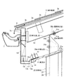
傾斜屋根3の軒先には、図2に示すように、鼻隠し3cが垂木3dの先端面に固定されて設けられている。この鼻隠し3cは木製の帯板状の鼻隠し板を上下に接合することによって構成されており、当該鼻隠し3cは、傾斜屋根3の下面より下方に延出している。
鼻隠し3cの上部には、軒樋7が鼻隠し3cと平行に固定されている。一方、野地板3aの先端上面には軒先水切り8が取り付けられており、この軒先水切り8は軒樋7に向けて延出しており、その先端は軒樋7の内側に位置している。
FIG. 1 is an enlarged view of the Y ellipse in FIGS. 3 (a) and 3 (b).
The
As shown in FIG. 2, the eaves of the
On the upper part of the
図1および図2に示すように、前記鼻隠し3cと建物本体2の外壁10との間は、傾斜屋根3の傾斜方向と平行に傾斜している軒天井11によって覆われている。この軒天井11の裏側(上面側)には野縁12,12が設けられている。野縁12,12は軒天井11の先端部と基端部とに配置されており、この野縁12,12に釘やビス等の止着材によって軒天井11が固定されている。なお、野縁12,12は例えば図示しない吊木等によって傾斜屋根3の垂木3dによって吊持されている。
前記軒天井11は、傾斜屋根3の下方に当該傾斜屋根3から所定距離離間して配置されるとともに、傾斜屋根3と平行に傾斜している。
As shown in FIGS. 1 and 2, a space between the
The
図2に示すように、鼻隠し3cの前面には、第1化粧板13が取り付けられており、この第1化粧板13の下端部は鼻隠し3cより下方で内側に直角に折曲されている。また、軒天井11の先端部には、第2化粧板14が取り付けられている。この第2化粧板14は凹溝を有しており、この凹溝に軒天井11の先端部を挿入することによって、当該軒天井11に取り付けられている。第1化粧板13の先端13aと、第2化粧板14の下端との間には、所定の通気用隙間15が設けられている。
また、鼻隠し3cの下面には、換気スリット部材16が前記軒天井11に向けて延出して取り付けられており、この延出した部分は前記第2化粧板14に、軒天井11の裏側で固定されている。換気スリット部材16は複数の換気孔16aを備えており、この換気孔16aは鼻隠し3cより内側に配置されている。さらに、換気スリット部材16には、火災時に発泡して換気スリット部材16と第1化粧板13の下壁部13bとの間の隙間を塞ぐ防火発泡材17が設けられている。
As shown in FIG. 2, the first
Further, a
図1に示すように、建物本体2には、バルコニー6が建物本体2から延出するようにして取り付けられている。バルコニー6の基端部は、建物本体2の1階を構成する建物ユニット1の天井梁または2階を構成する建物ユニット1の床梁に固定されている。
バルコニー6の上面には、ウッドデッキ18が設置されており、このウッドデッキ18の床面の高さは、建物本体2の2階の居室の床面の高さとほぼ等しくなっている。また、バルコニー6の下側に軒天井6aが設けられている。さらに、バルコニー6の外縁部には手摺壁6bが設けられている。
バルコニー6の先端部の下方には、ポーチ柱(柱)20が設けられている。このポーチ柱20は、四角筒状の鋼材で形成された柱本体21と、この柱本体21の外側に、当該柱本体21を覆うようにして外挿された筒状の化粧部材22とによって構成されている。柱本体21の下端部は地盤上に設置されたうえで、コンクリート製のポーチ23に埋設されている。また、柱本体21の上端部は前記軒天井6aを貫通し、バルコニー6に挿入されたうえで当該バルコニー6に固定されている。化粧部材22はポーチ23の上面と軒天井6aとの間において、柱本体21の外側に外挿されている。
このような構成のポーチ柱20は、傾斜屋根3の軒先長手方向(図1において紙面と直交する方向)に、所定間隔で複数配置されている。したがって、バルコニー6の先端部はこれらポーチ柱20によって下方にから支持されている。
As shown in FIG. 1, a
A
A pouch column (column) 20 is provided below the tip of the
A plurality of
前記バルコニー6の上方は、傾斜屋根3の軒先部によって覆われている。また、バルコニー6の先端部には、複数の支持柱25が傾斜屋根3の軒先長手方向(図1において紙面と直交する方向)に所定間隔で設けられている。そして、複数の支持柱25は前記ポーチ柱20の延長上に設けられている。つまり、支持柱25とポーチ柱20と同じ数だけ設けられ、かつ、平面視において同位置にかつ同間隔で配置されている。
支持柱25は、四角筒状の鋼材で形成された柱本体26と、この柱本体26の外側に、当該柱本体26を覆うようにして外挿された筒状の化粧部材27とによって構成されている。柱本体26の下端部はバルコニー6に挿入され、前記ポーチ柱20の柱本体21の上端部と連結されている。
化粧部材27はバルコニー6に設置されたウッドデッキ18の上面と軒天井11との間において、柱本体26の外側に外挿されている。また、図2に示すように、化粧部材27の先端(上端)は軒天井11と同方向に傾斜する傾斜板27aによって塞がれており、この傾斜板27aを前記柱本体26の上端部が貫通している。
The upper side of the
The
The
支持柱25の柱本体26の上端部は、図2に示すように、前記軒天井11を貫通しており、この柱本体26の上端には、この柱本体26の軸方向と傾斜し、かつ、傾斜屋根3の棟側を向く傾斜面26aが形成されている。
一方、前記傾斜屋根3と軒天井11との間には、軒先通し梁30が設けられている。この軒先通し梁30は、傾斜屋根3の軒先長手方向(図2において紙面と直交する方向)に延在する鋼材によって形成されている。
軒先通し梁30は、軒先長手方向に延在し、かつ鉛直に配置された帯板状の柱固定部30aと、この柱固定部30aの上縁に軒先長手方向に延在して形成され、かつ、傾斜屋根3の下面と平行に配置された帯板状の屋根固定部30bとから構成されている。
As shown in FIG. 2, the upper end portion of the column
On the other hand, an eaves through
The eaves-through
前記柱固定部30aには、ボルト挿通孔が形成されるとともに、当該ボルト挿通孔と同軸に設けられたナット31bが固定されている。これらボルト挿通孔およびナット31bは、柱固定部30aの長手方向(図2において紙面と直交する方向)に所定間隔で複数かつ、上下方向に所定間隔で二つ設けられている。
そして、このような柱固定部30aは前記支持柱25を構成する柱本体26の上端部側面に固定されている。つまり、柱本体26の軒先側を向く上端部側面に、柱固定部30aが当接され、ボルト31aとナット31bによって固定されている。柱本体26の上端部の側面には、ボルト挿通孔が前記柱固定部30aに形成されたボルト挿通孔と同軸に形成されており、これらボルト挿通孔にボルト31aを挿入してナット31bに螺合して締め付けることによって、柱固定部30aが柱本体26の上端部側面に固定されている。
そして、全ての支持柱25の柱本体26の上端部側面に軒先通し梁30の柱固定部30aを固定することによって、全ての支持柱25の上端部にこれらを連結するようにして軒先通し梁30が取り付けられている。
A bolt insertion hole is formed in the column fixing portion 30a, and a
Such a column fixing portion 30 a is fixed to the side surface of the upper end portion of the column
Then, by fixing the column fixing portions 30a of the eaves through
前記屋根固定部30bには、ボルト挿通孔が屋根固定部30bの長手方向(図2において紙面と直交する方向)に所定間隔で複数設けられている。
そして、このような屋根固定部30bは傾斜屋根3の下面を構成する垂木3dの下面に固定されている。つまり、垂木3dはH形鋼によって形成され、屋根固定部30bの長手方向(図2において紙面と直交する方向)に、所定間隔で複数配置されている。また、屋根固定部30bは、前記柱本体26の上端の傾斜面26aの上方に配置されている。さらに、各垂木3dの下フランジにボルト挿通孔が屋根固定部30bのボルト挿通孔に対向して形成されている。そして、これらボルト挿通孔にボルト31aを挿入してナット31bを螺合して締め付けることによって、屋根固定部30bが傾斜屋根3の下面に固定されている。ボルト31aを挿通する場合、前記傾斜面26aと屋根固定部30bと間の空間にボルト31aを配したうえで、前記ボルト挿通孔にボルト31aを挿入してナット31bを螺合して締め付ける。
このようにして、軒先通し梁30によって傾斜屋根3の軒先部が下方から支持されている。
The roof fixing portion 30b is provided with a plurality of bolt insertion holes at predetermined intervals in the longitudinal direction of the roof fixing portion 30b (the direction orthogonal to the paper surface in FIG. 2).
And such a roof fixing | fixed part 30b is being fixed to the lower surface of the
In this way, the eaves end portion of the
本実施の形態によれば、バルコニー6に複数の支持柱25が傾斜屋根3の軒先長手方向に所定間隔で設けられており、複数の支持柱25の上端部にこれらを連結するようにして軒先通し梁30が取り付けられ、この軒先通し梁30によって傾斜屋根3の軒先部が下方から支持されているので、バルコニー6上の傾斜屋根3の軒先部を確実に支持できる。
また、軒先通し梁30によって傾斜屋根3の軒先部を支持しているので、例えば、傾斜屋根3を複数の屋根パネルを横方向に接合して形成した場合であっても、傾斜屋根3の軒先部を屋根パネルの接合位置に拘わらず、確実に支持することができる。
また、軒先通し梁30の柱固定部30aが複数の支持柱25の柱本体26の上端部側面に固定されているので、複数の支持柱25の上端部を容易かつ強固に連結することができる。また、屋根固定部30bが傾斜屋根3の下面に固定されているので、軒先通し梁30によって傾斜屋根3を下方から安定的に支持できる。
According to the present embodiment, the plurality of
Moreover, since the eaves front part of the
Further, since the column fixing portions 30a of the eaves-end through
さらに、支持柱25の柱本体26の上端に形成された傾斜面26aの上方に、屋根固定部30bが配置され、この屋根固定部30bが傾斜屋根3の下面に固定されているので、傾斜面26aと屋根固定部30bとの間に設けられた空間を利用して屋根固定部30bを傾斜屋根3の下面にボルト止めによって強固に固定できる。
また、軒先通し梁30が傾斜屋根3と軒天井11との間に配置されているので、軒先通し梁30や、支持柱25と軒先通し梁30との接合部、軒先通し梁30と傾斜屋根3との接合部を隠すことができ、秀麗な仕上がりとすることができる。
また、建物本体2に、当該建物本体2から延出するようにして取り付けられたバルコニー6をその下方に設けられた複数のポーチ柱20によって下方から支持できる。また、これらポーチ柱20の延長上に前記支持柱25が設けられているので、支持柱25に傾斜屋根3の軒先部から作用する下向きの力を支持柱25からポーチ柱20に確実に伝達でき、よって、バルコニー6が建物本体2から延出するものであっても、傾斜屋根3の軒先部を確実に支持できる。
Further, the roof fixing portion 30b is disposed above the
Further, since the eaves through
Moreover, the
1 建物ユニット
2 建物本体
3 傾斜屋根
6 バルコニー
11 軒天井
20 ポーチ柱(柱)
22 支持柱
26a 傾斜面
30 軒先通し梁
30a 柱固定部
30b 屋根固定部
DESCRIPTION OF
22
Claims (4)
前記建物本体にバルコニーが設けられ、このバルコニーの上方が前記傾斜屋根によって覆われ、
前記バルコニーに複数の支持柱が前記傾斜屋根の軒先長手方向に所定間隔で設けられており、
前記複数の支持柱の上端部にこれらを連結するようにして軒先通し梁が取り付けられ、
この軒先通し梁によって前記傾斜屋根の軒先部が下方から支持されており、
前記軒先通し梁は、前記軒先長手方向に延在し、かつ鉛直に配置された帯板状の柱固定部と、この柱固定部の上縁に前記軒先長手方向に延在して形成され、かつ、前記傾斜屋根の下面と平行に配置された帯板状の屋根固定部とを備え、
前記柱固定部が前記複数の支持柱の上端部側面に固定され、前記屋根固定部が前記傾斜屋根の下面に固定されていることを特徴とする屋根軒先部の支持構造。 In the support structure of the roof eaves part that provides an inclined roof on the building body constructed by combining a plurality of building units, and supports the eaves part of this inclined roof,
A balcony is provided in the building body, and the upper part of the balcony is covered with the inclined roof,
A plurality of supporting columns are provided on the balcony at predetermined intervals in the eaves longitudinal direction of the inclined roof,
The eaves through beam is attached so as to connect these to the upper ends of the plurality of support pillars,
The eaves part of the inclined roof is supported from below by this eaves through beam ,
The eaves end through beam is formed to extend in the longitudinal direction of the eaves edge, and is formed to extend in the longitudinal direction of the eaves edge on the upper edge of the column fixing part, and a strip-like column fixing part arranged vertically. And a belt-like roof fixing portion arranged in parallel with the lower surface of the inclined roof,
The support structure of the roof eaves part characterized by the said pillar fixing | fixed part being fixed to the upper end part side surface of these support pillars, and the said roof fixing | fixed part being fixed to the lower surface of the said inclined roof .
前記支持柱の軒先側を向く上端部側面に前記柱固定部が固定され、
前記支持柱の上端に、この支持柱の軸方向と傾斜し、かつ、前記傾斜屋根の棟側を向く傾斜面が形成され、この傾斜面の上方に前記屋根固定部が配置され、この屋根固定部が傾斜屋根の下面に固定されていることを特徴とする屋根軒先部の支持構造。 In the support structure of the roof eaves part of Claim 1,
The column fixing portion is fixed to the side surface of the upper end portion facing the eaves side of the support column,
An inclined surface that is inclined with respect to the axial direction of the support column and faces the ridge side of the inclined roof is formed at the upper end of the support column, and the roof fixing portion is disposed above the inclined surface, and the roof fixing the support structure of the roof eaves portion which part is characterized in that it is fixed to the lower surface of the inclined swash roof.
前記建物本体にバルコニーが設けられ、このバルコニーの上方が前記傾斜屋根によって覆われ、
前記バルコニーに複数の支持柱が前記傾斜屋根の軒先長手方向に所定間隔で設けられており、
前記複数の支持柱の上端部にこれらを連結するようにして軒先通し梁が取り付けられ、
この軒先通し梁によって前記傾斜屋根の軒先部が下方から支持されており、
前記傾斜屋根の軒先部の下方に軒天井が設けられており、
前記軒先通し梁は前記傾斜屋根と軒天井との間に配置されていることを特徴とする屋根軒先部の支持構造。 In the support structure of the roof eaves part that provides an inclined roof on the building body constructed by combining a plurality of building units, and supports the eaves part of this inclined roof ,
A balcony is provided in the building body, and the upper part of the balcony is covered with the inclined roof,
A plurality of supporting columns are provided on the balcony at predetermined intervals in the eaves longitudinal direction of the inclined roof,
The eaves through beam is attached so as to connect these to the upper ends of the plurality of support pillars,
The eaves part of the inclined roof is supported from below by this eaves through beam,
An eaves ceiling is provided below the eaves part of the inclined roof,
The eaves-end through beam is disposed between the inclined roof and the eaves ceiling .
前記バルコニーは前記建物本体に、当該建物本体から延出するようにして取り付けられており、
前記バルコニーの先端部が当該バルコニーの下方に設けられた複数の柱によって下方から支持されており、
これら柱の延長上に前記支持柱が設けられていることを特徴とする屋根軒先部の支持構造。 In the support structure of the roof eaves part as described in any one of Claims 1-3,
The balcony is attached to the building body so as to extend from the building body,
The tip of the balcony is supported from below by a plurality of pillars provided below the balcony,
The support structure of the roof eaves part characterized by the said support pillar being provided on extension of these pillars .
Priority Applications (1)
| Application Number | Priority Date | Filing Date | Title |
|---|---|---|---|
| JP2011162693A JP5833854B2 (en) | 2011-07-26 | 2011-07-26 | Support structure for roof eaves |
Applications Claiming Priority (1)
| Application Number | Priority Date | Filing Date | Title |
|---|---|---|---|
| JP2011162693A JP5833854B2 (en) | 2011-07-26 | 2011-07-26 | Support structure for roof eaves |
Publications (2)
| Publication Number | Publication Date |
|---|---|
| JP2013024000A JP2013024000A (en) | 2013-02-04 |
| JP5833854B2 true JP5833854B2 (en) | 2015-12-16 |
Family
ID=47782669
Family Applications (1)
| Application Number | Title | Priority Date | Filing Date |
|---|---|---|---|
| JP2011162693A Expired - Fee Related JP5833854B2 (en) | 2011-07-26 | 2011-07-26 | Support structure for roof eaves |
Country Status (1)
| Country | Link |
|---|---|
| JP (1) | JP5833854B2 (en) |
Families Citing this family (1)
| Publication number | Priority date | Publication date | Assignee | Title |
|---|---|---|---|---|
| JP7323415B2 (en) * | 2019-10-16 | 2023-08-08 | 積水化学工業株式会社 | entrance porch |
Family Cites Families (2)
| Publication number | Priority date | Publication date | Assignee | Title |
|---|---|---|---|---|
| JP2918356B2 (en) * | 1991-06-17 | 1999-07-12 | 積水化学工業株式会社 | Eaves structure of unit house |
| JPH08158469A (en) * | 1994-12-06 | 1996-06-18 | Misawa Homes Co Ltd | Joined structure of fireproof covered and attached unit |
-
2011
- 2011-07-26 JP JP2011162693A patent/JP5833854B2/en not_active Expired - Fee Related
Also Published As
| Publication number | Publication date |
|---|---|
| JP2013024000A (en) | 2013-02-04 |
Similar Documents
| Publication | Publication Date | Title |
|---|---|---|
| JP6233370B2 (en) | Housing structure | |
| JP6349207B2 (en) | Fireproof structure of balcony | |
| JP5833854B2 (en) | Support structure for roof eaves | |
| JP6795940B2 (en) | Connecting member | |
| JP5461279B2 (en) | building | |
| JP2008223358A (en) | Building construction method | |
| JP4870645B2 (en) | housing complex | |
| JP6898129B2 (en) | Railings and buildings in the outer corridor | |
| JP6096659B2 (en) | Wooden frame building | |
| JP7201452B2 (en) | building unit | |
| JP6581354B2 (en) | building | |
| JP2006233699A (en) | Building structure | |
| JP2008196264A (en) | Structure of balcony | |
| JP2024098870A (en) | Roof structure for building | |
| JP6415194B2 (en) | Gap roof structure | |
| JP4227888B2 (en) | Wall panel and wall panel mounting structure | |
| JP5967895B2 (en) | Floor structure | |
| JP2017179693A (en) | Support structure for support post of handrail | |
| JP3571485B2 (en) | Insulation inner wall foundation method of window opening | |
| JPH11236731A (en) | Wooden building and execution method of feather pattern material thereof | |
| JP2021134593A (en) | Boundary wall structure | |
| JP6433285B2 (en) | Roof panel mounting structure | |
| JP2987107B2 (en) | Dwelling unit | |
| JP2021038590A (en) | Building material panel, and structure constructed by using the same | |
| JP2009057776A (en) | Wooden building construction method and wooden building |
Legal Events
| Date | Code | Title | Description |
|---|---|---|---|
| A621 | Written request for application examination |
Free format text: JAPANESE INTERMEDIATE CODE: A621 Effective date: 20140709 |
|
| A977 | Report on retrieval |
Free format text: JAPANESE INTERMEDIATE CODE: A971007 Effective date: 20150323 |
|
| A131 | Notification of reasons for refusal |
Free format text: JAPANESE INTERMEDIATE CODE: A131 Effective date: 20150331 |
|
| A521 | Request for written amendment filed |
Free format text: JAPANESE INTERMEDIATE CODE: A523 Effective date: 20150522 |
|
| TRDD | Decision of grant or rejection written | ||
| A01 | Written decision to grant a patent or to grant a registration (utility model) |
Free format text: JAPANESE INTERMEDIATE CODE: A01 Effective date: 20151027 |
|
| A61 | First payment of annual fees (during grant procedure) |
Free format text: JAPANESE INTERMEDIATE CODE: A61 Effective date: 20151030 |
|
| R150 | Certificate of patent or registration of utility model |
Ref document number: 5833854 Country of ref document: JP Free format text: JAPANESE INTERMEDIATE CODE: R150 |
|
| R250 | Receipt of annual fees |
Free format text: JAPANESE INTERMEDIATE CODE: R250 |
|
| R250 | Receipt of annual fees |
Free format text: JAPANESE INTERMEDIATE CODE: R250 |
|
| R250 | Receipt of annual fees |
Free format text: JAPANESE INTERMEDIATE CODE: R250 |
|
| LAPS | Cancellation because of no payment of annual fees |