JP4628801B2 - Liquid crystal display device - Google Patents
Liquid crystal display device Download PDFInfo
- Publication number
- JP4628801B2 JP4628801B2 JP2005011519A JP2005011519A JP4628801B2 JP 4628801 B2 JP4628801 B2 JP 4628801B2 JP 2005011519 A JP2005011519 A JP 2005011519A JP 2005011519 A JP2005011519 A JP 2005011519A JP 4628801 B2 JP4628801 B2 JP 4628801B2
- Authority
- JP
- Japan
- Prior art keywords
- liquid crystal
- crystal display
- display device
- pixel
- electrode
- Prior art date
- Legal status (The legal status is an assumption and is not a legal conclusion. Google has not performed a legal analysis and makes no representation as to the accuracy of the status listed.)
- Expired - Fee Related
Links
Images


Classifications
-
- G—PHYSICS
- G02—OPTICS
- G02F—OPTICAL DEVICES OR ARRANGEMENTS FOR THE CONTROL OF LIGHT BY MODIFICATION OF THE OPTICAL PROPERTIES OF THE MEDIA OF THE ELEMENTS INVOLVED THEREIN; NON-LINEAR OPTICS; FREQUENCY-CHANGING OF LIGHT; OPTICAL LOGIC ELEMENTS; OPTICAL ANALOGUE/DIGITAL CONVERTERS
- G02F1/00—Devices or arrangements for the control of the intensity, colour, phase, polarisation or direction of light arriving from an independent light source, e.g. switching, gating or modulating; Non-linear optics
- G02F1/01—Devices or arrangements for the control of the intensity, colour, phase, polarisation or direction of light arriving from an independent light source, e.g. switching, gating or modulating; Non-linear optics for the control of the intensity, phase, polarisation or colour
- G02F1/13—Devices or arrangements for the control of the intensity, colour, phase, polarisation or direction of light arriving from an independent light source, e.g. switching, gating or modulating; Non-linear optics for the control of the intensity, phase, polarisation or colour based on liquid crystals, e.g. single liquid crystal display cells
- G02F1/133—Constructional arrangements; Operation of liquid crystal cells; Circuit arrangements
- G02F1/1333—Constructional arrangements; Manufacturing methods
- G02F1/1337—Surface-induced orientation of the liquid crystal molecules, e.g. by alignment layers
- G02F1/133707—Structures for producing distorted electric fields, e.g. bumps, protrusions, recesses, slits in pixel electrodes
-
- G—PHYSICS
- G02—OPTICS
- G02F—OPTICAL DEVICES OR ARRANGEMENTS FOR THE CONTROL OF LIGHT BY MODIFICATION OF THE OPTICAL PROPERTIES OF THE MEDIA OF THE ELEMENTS INVOLVED THEREIN; NON-LINEAR OPTICS; FREQUENCY-CHANGING OF LIGHT; OPTICAL LOGIC ELEMENTS; OPTICAL ANALOGUE/DIGITAL CONVERTERS
- G02F1/00—Devices or arrangements for the control of the intensity, colour, phase, polarisation or direction of light arriving from an independent light source, e.g. switching, gating or modulating; Non-linear optics
- G02F1/01—Devices or arrangements for the control of the intensity, colour, phase, polarisation or direction of light arriving from an independent light source, e.g. switching, gating or modulating; Non-linear optics for the control of the intensity, phase, polarisation or colour
- G02F1/13—Devices or arrangements for the control of the intensity, colour, phase, polarisation or direction of light arriving from an independent light source, e.g. switching, gating or modulating; Non-linear optics for the control of the intensity, phase, polarisation or colour based on liquid crystals, e.g. single liquid crystal display cells
- G02F1/133—Constructional arrangements; Operation of liquid crystal cells; Circuit arrangements
- G02F1/1333—Constructional arrangements; Manufacturing methods
- G02F1/1337—Surface-induced orientation of the liquid crystal molecules, e.g. by alignment layers
-
- G—PHYSICS
- G02—OPTICS
- G02F—OPTICAL DEVICES OR ARRANGEMENTS FOR THE CONTROL OF LIGHT BY MODIFICATION OF THE OPTICAL PROPERTIES OF THE MEDIA OF THE ELEMENTS INVOLVED THEREIN; NON-LINEAR OPTICS; FREQUENCY-CHANGING OF LIGHT; OPTICAL LOGIC ELEMENTS; OPTICAL ANALOGUE/DIGITAL CONVERTERS
- G02F1/00—Devices or arrangements for the control of the intensity, colour, phase, polarisation or direction of light arriving from an independent light source, e.g. switching, gating or modulating; Non-linear optics
- G02F1/01—Devices or arrangements for the control of the intensity, colour, phase, polarisation or direction of light arriving from an independent light source, e.g. switching, gating or modulating; Non-linear optics for the control of the intensity, phase, polarisation or colour
- G02F1/13—Devices or arrangements for the control of the intensity, colour, phase, polarisation or direction of light arriving from an independent light source, e.g. switching, gating or modulating; Non-linear optics for the control of the intensity, phase, polarisation or colour based on liquid crystals, e.g. single liquid crystal display cells
- G02F1/133—Constructional arrangements; Operation of liquid crystal cells; Circuit arrangements
- G02F1/136—Liquid crystal cells structurally associated with a semi-conducting layer or substrate, e.g. cells forming part of an integrated circuit
- G02F1/1362—Active matrix addressed cells
- G02F1/136213—Storage capacitors associated with the pixel electrode
-
- G—PHYSICS
- G02—OPTICS
- G02F—OPTICAL DEVICES OR ARRANGEMENTS FOR THE CONTROL OF LIGHT BY MODIFICATION OF THE OPTICAL PROPERTIES OF THE MEDIA OF THE ELEMENTS INVOLVED THEREIN; NON-LINEAR OPTICS; FREQUENCY-CHANGING OF LIGHT; OPTICAL LOGIC ELEMENTS; OPTICAL ANALOGUE/DIGITAL CONVERTERS
- G02F1/00—Devices or arrangements for the control of the intensity, colour, phase, polarisation or direction of light arriving from an independent light source, e.g. switching, gating or modulating; Non-linear optics
- G02F1/01—Devices or arrangements for the control of the intensity, colour, phase, polarisation or direction of light arriving from an independent light source, e.g. switching, gating or modulating; Non-linear optics for the control of the intensity, phase, polarisation or colour
- G02F1/13—Devices or arrangements for the control of the intensity, colour, phase, polarisation or direction of light arriving from an independent light source, e.g. switching, gating or modulating; Non-linear optics for the control of the intensity, phase, polarisation or colour based on liquid crystals, e.g. single liquid crystal display cells
- G02F1/133—Constructional arrangements; Operation of liquid crystal cells; Circuit arrangements
- G02F1/1333—Constructional arrangements; Manufacturing methods
- G02F1/1339—Gaskets; Spacers; Sealing of cells
- G02F1/13394—Gaskets; Spacers; Sealing of cells spacers regularly patterned on the cell subtrate, e.g. walls, pillars
-
- G—PHYSICS
- G02—OPTICS
- G02F—OPTICAL DEVICES OR ARRANGEMENTS FOR THE CONTROL OF LIGHT BY MODIFICATION OF THE OPTICAL PROPERTIES OF THE MEDIA OF THE ELEMENTS INVOLVED THEREIN; NON-LINEAR OPTICS; FREQUENCY-CHANGING OF LIGHT; OPTICAL LOGIC ELEMENTS; OPTICAL ANALOGUE/DIGITAL CONVERTERS
- G02F1/00—Devices or arrangements for the control of the intensity, colour, phase, polarisation or direction of light arriving from an independent light source, e.g. switching, gating or modulating; Non-linear optics
- G02F1/01—Devices or arrangements for the control of the intensity, colour, phase, polarisation or direction of light arriving from an independent light source, e.g. switching, gating or modulating; Non-linear optics for the control of the intensity, phase, polarisation or colour
- G02F1/13—Devices or arrangements for the control of the intensity, colour, phase, polarisation or direction of light arriving from an independent light source, e.g. switching, gating or modulating; Non-linear optics for the control of the intensity, phase, polarisation or colour based on liquid crystals, e.g. single liquid crystal display cells
- G02F1/133—Constructional arrangements; Operation of liquid crystal cells; Circuit arrangements
- G02F1/1333—Constructional arrangements; Manufacturing methods
- G02F1/1339—Gaskets; Spacers; Sealing of cells
- G02F1/13396—Spacers having different sizes
-
- G—PHYSICS
- G02—OPTICS
- G02F—OPTICAL DEVICES OR ARRANGEMENTS FOR THE CONTROL OF LIGHT BY MODIFICATION OF THE OPTICAL PROPERTIES OF THE MEDIA OF THE ELEMENTS INVOLVED THEREIN; NON-LINEAR OPTICS; FREQUENCY-CHANGING OF LIGHT; OPTICAL LOGIC ELEMENTS; OPTICAL ANALOGUE/DIGITAL CONVERTERS
- G02F1/00—Devices or arrangements for the control of the intensity, colour, phase, polarisation or direction of light arriving from an independent light source, e.g. switching, gating or modulating; Non-linear optics
- G02F1/01—Devices or arrangements for the control of the intensity, colour, phase, polarisation or direction of light arriving from an independent light source, e.g. switching, gating or modulating; Non-linear optics for the control of the intensity, phase, polarisation or colour
- G02F1/13—Devices or arrangements for the control of the intensity, colour, phase, polarisation or direction of light arriving from an independent light source, e.g. switching, gating or modulating; Non-linear optics for the control of the intensity, phase, polarisation or colour based on liquid crystals, e.g. single liquid crystal display cells
- G02F1/133—Constructional arrangements; Operation of liquid crystal cells; Circuit arrangements
- G02F1/1333—Constructional arrangements; Manufacturing methods
- G02F1/1343—Electrodes
- G02F1/134309—Electrodes characterised by their geometrical arrangement
- G02F1/134345—Subdivided pixels, e.g. for grey scale or redundancy
- G02F1/134354—Subdivided pixels, e.g. for grey scale or redundancy the sub-pixels being capacitively coupled
-
- G—PHYSICS
- G02—OPTICS
- G02F—OPTICAL DEVICES OR ARRANGEMENTS FOR THE CONTROL OF LIGHT BY MODIFICATION OF THE OPTICAL PROPERTIES OF THE MEDIA OF THE ELEMENTS INVOLVED THEREIN; NON-LINEAR OPTICS; FREQUENCY-CHANGING OF LIGHT; OPTICAL LOGIC ELEMENTS; OPTICAL ANALOGUE/DIGITAL CONVERTERS
- G02F1/00—Devices or arrangements for the control of the intensity, colour, phase, polarisation or direction of light arriving from an independent light source, e.g. switching, gating or modulating; Non-linear optics
- G02F1/01—Devices or arrangements for the control of the intensity, colour, phase, polarisation or direction of light arriving from an independent light source, e.g. switching, gating or modulating; Non-linear optics for the control of the intensity, phase, polarisation or colour
- G02F1/13—Devices or arrangements for the control of the intensity, colour, phase, polarisation or direction of light arriving from an independent light source, e.g. switching, gating or modulating; Non-linear optics for the control of the intensity, phase, polarisation or colour based on liquid crystals, e.g. single liquid crystal display cells
- G02F1/133—Constructional arrangements; Operation of liquid crystal cells; Circuit arrangements
- G02F1/136—Liquid crystal cells structurally associated with a semi-conducting layer or substrate, e.g. cells forming part of an integrated circuit
- G02F1/1362—Active matrix addressed cells
- G02F1/136218—Shield electrodes
-
- G—PHYSICS
- G02—OPTICS
- G02F—OPTICAL DEVICES OR ARRANGEMENTS FOR THE CONTROL OF LIGHT BY MODIFICATION OF THE OPTICAL PROPERTIES OF THE MEDIA OF THE ELEMENTS INVOLVED THEREIN; NON-LINEAR OPTICS; FREQUENCY-CHANGING OF LIGHT; OPTICAL LOGIC ELEMENTS; OPTICAL ANALOGUE/DIGITAL CONVERTERS
- G02F1/00—Devices or arrangements for the control of the intensity, colour, phase, polarisation or direction of light arriving from an independent light source, e.g. switching, gating or modulating; Non-linear optics
- G02F1/01—Devices or arrangements for the control of the intensity, colour, phase, polarisation or direction of light arriving from an independent light source, e.g. switching, gating or modulating; Non-linear optics for the control of the intensity, phase, polarisation or colour
- G02F1/13—Devices or arrangements for the control of the intensity, colour, phase, polarisation or direction of light arriving from an independent light source, e.g. switching, gating or modulating; Non-linear optics for the control of the intensity, phase, polarisation or colour based on liquid crystals, e.g. single liquid crystal display cells
- G02F1/137—Devices or arrangements for the control of the intensity, colour, phase, polarisation or direction of light arriving from an independent light source, e.g. switching, gating or modulating; Non-linear optics for the control of the intensity, phase, polarisation or colour based on liquid crystals, e.g. single liquid crystal display cells characterised by the electro-optical or magneto-optical effect, e.g. field-induced phase transition, orientation effect, guest-host interaction or dynamic scattering
- G02F1/139—Devices or arrangements for the control of the intensity, colour, phase, polarisation or direction of light arriving from an independent light source, e.g. switching, gating or modulating; Non-linear optics for the control of the intensity, phase, polarisation or colour based on liquid crystals, e.g. single liquid crystal display cells characterised by the electro-optical or magneto-optical effect, e.g. field-induced phase transition, orientation effect, guest-host interaction or dynamic scattering based on orientation effects in which the liquid crystal remains transparent
- G02F1/1393—Devices or arrangements for the control of the intensity, colour, phase, polarisation or direction of light arriving from an independent light source, e.g. switching, gating or modulating; Non-linear optics for the control of the intensity, phase, polarisation or colour based on liquid crystals, e.g. single liquid crystal display cells characterised by the electro-optical or magneto-optical effect, e.g. field-induced phase transition, orientation effect, guest-host interaction or dynamic scattering based on orientation effects in which the liquid crystal remains transparent the birefringence of the liquid crystal being electrically controlled, e.g. ECB-, DAP-, HAN-, PI-LC cells
-
- G—PHYSICS
- G02—OPTICS
- G02F—OPTICAL DEVICES OR ARRANGEMENTS FOR THE CONTROL OF LIGHT BY MODIFICATION OF THE OPTICAL PROPERTIES OF THE MEDIA OF THE ELEMENTS INVOLVED THEREIN; NON-LINEAR OPTICS; FREQUENCY-CHANGING OF LIGHT; OPTICAL LOGIC ELEMENTS; OPTICAL ANALOGUE/DIGITAL CONVERTERS
- G02F2201/00—Constructional arrangements not provided for in groups G02F1/00 - G02F7/00
- G02F2201/12—Constructional arrangements not provided for in groups G02F1/00 - G02F7/00 electrode
- G02F2201/123—Constructional arrangements not provided for in groups G02F1/00 - G02F7/00 electrode pixel
Landscapes
- Physics & Mathematics (AREA)
- Nonlinear Science (AREA)
- Mathematical Physics (AREA)
- Chemical & Material Sciences (AREA)
- Crystallography & Structural Chemistry (AREA)
- General Physics & Mathematics (AREA)
- Optics & Photonics (AREA)
- Engineering & Computer Science (AREA)
- Spectroscopy & Molecular Physics (AREA)
- Power Engineering (AREA)
- Microelectronics & Electronic Packaging (AREA)
- Liquid Crystal (AREA)
Description
本発明は、液晶分子の配向方向が相互に異なる複数の配向領域を1画素内に有するMVA(Multi−domain Vertical Alignment)方式の液晶表示装置に関し、特に、画素領域が複数の副画素に分割されている液晶表示装置に関する。 The present invention relates to an MVA (Multi-domain Vertical Alignment) type liquid crystal display device in which a plurality of alignment regions having different alignment directions of liquid crystal molecules are included in one pixel, and in particular, the pixel region is divided into a plurality of sub-pixels. The present invention relates to a liquid crystal display device.
液晶表示装置は、CRT(Cathode Ray Tube)に比べて薄くて軽量であり、かつ低電圧で駆動できて消費電力が小さいという利点を有している。そのため、液晶表示装置は、ノート型PC(パーソナルコンピュータ)、PDA(携帯情報端末)及び携帯電話など、種々の電子機器に用いられている。特に、各画素(サブ画素)毎にスイッチング素子としてTFT(Thin Film Transistor:薄膜トランジスタ)を設けたアクティブマトリクス型液晶表示装置は、高い駆動能力を有している。アクティブマトリクス型液晶表示装置は、CRTにも匹敵する優れた表示特性が得られるため、デスクトップ型PCやテレビ受像機など従来CRTが用いられていた用途にも広く用いられるようになっている。 The liquid crystal display device is advantageous in that it is thinner and lighter than a CRT (Cathode Ray Tube) and can be driven at a low voltage and consumes less power. Therefore, liquid crystal display devices are used in various electronic devices such as notebook PCs (personal computers), PDAs (personal digital assistants), and mobile phones. In particular, an active matrix liquid crystal display device in which a TFT (Thin Film Transistor) is provided as a switching element for each pixel (sub-pixel) has a high driving capability. An active matrix type liquid crystal display device has excellent display characteristics comparable to that of a CRT, and is therefore widely used in applications where a conventional CRT has been used, such as a desktop PC and a television receiver.
図15は、従来の液晶表示装置の概略の断面構成を示している。図15に示すように、液晶表示装置は、液晶表示パネル101を有している。液晶表示パネル101は、TFTや画素電極が画素毎に形成されたTFT基板102と、カラーフィルタ(CF)や共通電極が形成された対向基板104と、両基板102、104間に封止された液晶106とを有している。TFT基板102は、接続端子が設けられるため対向基板104よりも大きく形成されている。両基板102、104は、外周部に塗布されたシール材152を介して貼り合わされている。両基板102、104間のセルギャップは、例えば球状スペーサ146により維持されている。また、液晶表示パネル101を挟んで外側には、偏光板187、186が配置されている。偏光板187の図中下方には、バックライトユニット(図示せず)が配置されている。
FIG. 15 shows a schematic cross-sectional structure of a conventional liquid crystal display device. As shown in FIG. 15, the liquid crystal display device has a liquid
従来は、正の誘電率異方性を有する水平配向型液晶を備え、液晶分子をツイスト配向させるTN(Twisted Nematic)モードの液晶表示装置が広く用いられていた。しかし、TNモードの液晶表示装置は、視野角特性が悪く、画面を斜め方向から見たときにコントラストや色調が大きく変化するという欠点を有している。このため、視野角特性が良好なVA(Vertically Aligned)モードの液晶表示装置及びMVA方式の液晶表示装置が開発され、実用化されている。 Conventionally, a TN (twisted nematic) mode liquid crystal display device having a horizontal alignment type liquid crystal having a positive dielectric anisotropy and twist aligning liquid crystal molecules has been widely used. However, the TN mode liquid crystal display device has the disadvantage that the viewing angle characteristics are poor and the contrast and color tone change greatly when the screen is viewed from an oblique direction. For this reason, VA (Vertically Aligned) mode liquid crystal display devices and MVA liquid crystal display devices with good viewing angle characteristics have been developed and put into practical use.
図16(a)、(b)は、MVA方式の液晶表示装置の断面構成を模式的に示している。TFT基板102及び対向基板104の間には、負の誘電率異方性を有する垂直配向型の液晶106が封止されている。TFT基板102の画素電極116上には、液晶106の配向を規制する配向規制用構造物として土手状の線状突起143が形成されている。画素電極116上及び線状突起143上には、例えばポリイミドからなる垂直配向膜150が形成されている。
FIGS. 16A and 16B schematically show a cross-sectional configuration of an MVA liquid crystal display device. A vertical alignment type
対向基板104の共通電極141上には、配向規制用構造物として土手状の線状突起142が形成されている。線状突起142は、TFT基板102側の線状突起143に並列して延び、線状突起143に対し半ピッチずれて配置されている。共通電極141上及び線状突起142上には、例えばポリイミドからなる垂直配向膜151が形成されている。
On the
MVA方式の液晶表示装置においては、画素電極116と共通電極141との間に電圧を印加しない状態では、図16(a)に示すように、ほとんどの液晶分子108は基板面に対しほぼ垂直に配向する。但し、線状突起142、143近傍の液晶分子108は、線状突起142、143の傾斜面にほぼ垂直な方向に配向する。
In the MVA liquid crystal display device, when no voltage is applied between the
画素電極116と共通電極141との間に所定の電圧を印加すると、電界の影響により液晶分子108は基板面に対し斜めに傾斜する。この場合に、図16(b)に示すように、線状突起142、143の両側では液晶分子108の傾斜方向が異なる。これにより、いわゆる配向分割(マルチドメイン)が実現できる。
When a predetermined voltage is applied between the
図16(b)に示すように、MVA方式の液晶表示装置では、電圧を印加したときの液晶分子108の傾斜方向が線状突起142、143の両側で異なるので、斜め方向への光の漏れが抑制され、優れた視野角特性が得られる。
As shown in FIG. 16B, in the MVA liquid crystal display device, the tilt direction of the
上記の例では配向規制用構造物が線状突起142、143の場合について説明したが、電極が部分的に除去されたスリットや、基板表面の窪み(溝)を配向規制用構造物とすることもある。また、図16(a)、(b)ではTFT基板102及び対向基板104の両方に配向規制用構造物を設けた例について説明したが、TFT基板102及び対向基板104のうちのいずれか一方のみに配向規制用構造物を形成してもよい。
In the above example, the case where the alignment regulating structure is the
図17は、TFT基板102側の画素電極116のみに、配向規制用構造物としてスリット145を形成した例を示している。スリット145の縁部付近では電界に歪みが生じ、電気力線が基板面に対し斜め方向に延びるので、スリット145の両側で液晶分子108の傾斜方向が異なる。これにより配向分割が実現でき、視野角特性が向上する。
FIG. 17 shows an example in which a
図18は、TFT基板102側にスリット145が形成され、対向基板104側に線状突起142が形成されたMVA方式の液晶表示装置の1画素の構成を示している。図19は、図18のX−X線で切断したTFT基板102の断面構成を示している。図18及び図19に示すように、TFT基板102には、図中左右方向に延びる複数のゲートバスライン112と、図中上下方向に延びる複数のドレインバスライン114とがそれぞれ所定のピッチで配置されている。これらのゲートバスライン112及びドレインバスライン114により長方形状の画素領域が画定されている。また、TFT基板102には、ゲートバスライン112に並列して画素領域の中央部を横断する蓄積容量バスライン118が形成されている。ゲートバスライン112及び蓄積容量バスライン118とドレインバスライン114との間には絶縁膜130が形成されている。絶縁膜130によりゲートバスライン112とドレインバスライン114との間、及び蓄積容量バスライン118とドレインバスライン114との間が電気的に分離されている。
FIG. 18 shows a configuration of one pixel of an MVA liquid crystal display device in which a
画素領域毎に、TFT120、画素電極116及び蓄積容量電極119が形成されている。TFT120は、ゲートバスライン112の一部をゲート電極としている。また、TFT120のドレイン電極121はドレインバスライン114に接続しており、ソース電極122はゲートバスライン112を挟んでドレイン電極121に対向する位置に形成されている。さらに、蓄積容量電極119は、絶縁膜130を挟んで蓄積容量バスライン118に対向する位置に形成されている。
A
蓄積容量電極119、TFT120及びドレインバスライン114は保護膜131に覆われており、画素電極116は保護膜131の上に配置される。画素電極116はITO(Indium−Tin Oxide)等の透明導電膜からなり、保護膜131に形成されたコンタクトホール125、126を介してTFT120のソース電極122及び蓄積容量電極119にそれぞれ電気的に接続されている。また、画素電極116には、斜め方向に延びる2本のスリット145が蓄積容量バスラインに対してほぼ線対称に形成されている。画素電極116の表面は、例えばポリイミドからなる垂直配向膜(図示せず)により覆われている。
The
TFT基板102に対向して配置される対向基板には、遮光膜(BM)、CF樹脂層及び共通電極141が形成されている。共通電極141の上には、ゲートバスライン112及び蓄積容量バスライン118の上方で屈曲する複数の土手状の線状突起142が形成されている。線状突起142は、画素電極116のスリット145に対し半ピッチずれて並列配置されている。
A light-shielding film (BM), a CF resin layer, and a
このようなMVA方式の液晶表示装置において、画素電極116と共通電極141との間に所定の電圧を印加すると、図18及び図20に示すように、液晶分子108の配向方向が相互に異なる4つの配向領域α、β、γ、δが形成される。配向領域α〜δは、線状突起142及びスリット145を境界として分割されている。配向領域α〜δの面積が1画素内で互いにほぼ等しくなるように線状突起142及びスリット145を形成すると、液晶表示装置の視野角特性の方向依存性が小さくなる。
In such an MVA liquid crystal display device, when a predetermined voltage is applied between the
ところで、従来のMVA方式の液晶表示装置では、画面を斜め方向から見たときに白っぽくなる現象が発生する。図21は、従来のMVA方式の液晶表示装置の印加電圧に対する透過率特性(T−V特性)を示すグラフである。横軸は液晶層に対する印加電圧(V)を表し、縦軸は光の透過率を表している。線Lは表示画面に対し垂直な方向(以下、「正面方向」という)でのT−V特性を示し、線Mは表示画面に対して方位角90°、極角60°の方向(以下、「斜め方向」という)でのT−V特性を示している。ここで、方位角は、表示画面の右方向を基準として反時計回りに計った角度とする。また極角は、表示画面の中心に立てた垂線となす角度とする。 By the way, in the conventional MVA type liquid crystal display device, a phenomenon of becoming whitish occurs when the screen is viewed from an oblique direction. FIG. 21 is a graph showing transmittance characteristics (TV characteristics) with respect to applied voltage of a conventional MVA liquid crystal display device. The horizontal axis represents the applied voltage (V) to the liquid crystal layer, and the vertical axis represents the light transmittance. A line L represents a TV characteristic in a direction perpendicular to the display screen (hereinafter referred to as “front direction”), and a line M represents a direction with an azimuth angle of 90 ° and a polar angle of 60 ° (hereinafter referred to as “front direction”). The TV characteristic in the “oblique direction” is shown. Here, the azimuth angle is an angle measured counterclockwise with respect to the right direction of the display screen. Further, the polar angle is an angle formed with a perpendicular line standing at the center of the display screen.
図21に示すように、約3V以上の比較的高い電圧を液晶層に印加したときには、正面方向の透過率が斜め方向の透過率よりも高くなっている。これに対し、閾値電圧より若干高い約2〜3Vの電圧を液晶層に印加したとき(円で囲んだ領域)には、斜め方向の透過率が正面方向の透過率より高くなる。この結果、斜め方向から表示画面を見た場合には、実効駆動電圧範囲での輝度差が小さくなってしまう。この現象は色の変化に最も顕著に現れる。すなわち、R、G、Bの3原色の輝度差が小さくなるため、斜め方向から見ると画面全体の色が白っぽくなり、色の再現性が低下してしまうという現象が生じる。この現象は、白茶け(discolor)と呼ばれている。白茶けは、MVA方式の液晶表示装置だけでなく、TNモードの液晶表示装置でも発生する。 As shown in FIG. 21, when a relatively high voltage of about 3 V or higher is applied to the liquid crystal layer, the transmittance in the front direction is higher than the transmittance in the oblique direction. On the other hand, when a voltage of about 2 to 3 V, which is slightly higher than the threshold voltage, is applied to the liquid crystal layer (a region surrounded by a circle), the transmittance in the oblique direction is higher than the transmittance in the front direction. As a result, when the display screen is viewed from an oblique direction, the luminance difference in the effective drive voltage range becomes small. This phenomenon appears most prominently in color changes. That is, since the luminance difference between the three primary colors of R, G, and B is small, the color of the entire screen becomes whitish when viewed from an oblique direction, and the color reproducibility is lowered. This phenomenon is called “discolor”. White-brown occurs not only in MVA liquid crystal display devices but also in TN mode liquid crystal display devices.
特許文献1には、1つの画素を複数の副画素に分割して、それらの副画素を容量結合することが提案されている。このような液晶表示装置では、各副画素の容量比によって電位が分割されるため、各副画素の液晶に相互に異なる電圧を印加することができる。したがって、見かけ上、1つの画素にT−V特性のしきい値が異なる複数の領域が存在することになる。このように1つの画素にT−V特性のしきい値が異なる複数の領域が存在すると、図21の円内に示したような正面方向の透過率よりも斜め方向の透過率が高くなる現象が抑制され、その結果画面が白っぽくなる現象も抑制される。このように1つの画素を容量結合した複数の副画素に分割して表示特性を改善する方法は、容量結合HT(ハーフトーン・グレースケール)法と呼ばれる。
特許文献2には、図22に示すように、画素電極を4つの副画素電極116a〜116dに分割し、各副画素電極116a〜116dの下方に絶縁膜を介して制御容量電極117a〜117dをそれぞれ配置した構成を有する液晶表示装置が開示されている。この液晶表示装置では、制御容量電極117a〜117dの大きさがそれぞれ異なっており、TFT120を介して制御容量電極117a〜117dに表示電圧が印加されるようになっている。また、副画素電極116a〜116dの間から光が漏れることを防止するために、副画素電極116a〜116dの間にも制御容量電極115が配置されている。
In
特許文献3にも、1つの画素を複数の副画素に分割した液晶表示装置が開示されている。この液晶表示装置では、例えば副画素毎にラビング処理条件を変化させて、副画素の液晶分子のプレチルト角を相互に異ならせている。
これらの従来の技術は、いずれもTNモードの液晶表示装置に関するものである。
These conventional technologies all relate to a TN mode liquid crystal display device.
図23は、容量結合HT法を用いた従来のMVA方式の液晶表示装置の1画素の構成を示している。図24は、図23のY−Y線で切断した液晶表示装置の断面構成を示している。図23及び図24に示すように、TFT基板102は、ガラス基板110上に形成された複数のゲートバスライン112と、絶縁膜130を介してゲートバスライン112に交差する複数のドレインバスライン114とを有している。ゲートバスライン112のピッチは例えば約300μmであり、ドレインバスライン114のピッチは例えば約100μmである。これらのゲートバスライン112及びドレインバスライン114により長方形状の画素領域が画定されている。また、TFT基板102には、ゲートバスライン112に並列して画素領域の中央部を横断する蓄積容量バスライン118が形成されている。
FIG. 23 shows a configuration of one pixel of a conventional MVA liquid crystal display device using the capacitive coupling HT method. FIG. 24 shows a cross-sectional configuration of the liquid crystal display device taken along line YY in FIG. As shown in FIGS. 23 and 24, the
TFT基板102には、TFT120、制御容量電極133、134及び画素電極116a〜116dが画素領域毎に形成されている。画素電極116a〜116dは、スリット145により互いに分割されている。スリット145は斜め方向に延び、蓄積容量バスライン118に対してほぼ線対称に形成されている。
On the
TFT120は、ゲートバスライン112の一部をゲート電極としている。TFT120のドレイン電極121は、ドレインバスライン114に電気的に接続されている。ソース電極122は、ゲートバスライン112上に形成されたチャネル保護膜128を介してドレイン電極121に対向する位置に配置されている。またソース電極122は、制御容量電極133、134に電気的に接続されている。
The
副画素電極116a〜116dはITO等の透明導電膜からなり、互いに同層に形成されている。これらの副画素電極116a〜116dを分離するスリット145の幅は例えば10μmである。副画素電極116aはコンタクトホール125を介して制御容量電極133に電気的に接続され、副画素電極116dはコンタクトホール127を介して制御容量電極133に電気的に接続されている。副画素電極116b、116cの一部の領域は、制御容量電極133(134)に保護膜131を介して重なっている。副画素電極116b、116cは、当該領域に形成される制御容量を介した容量結合により、制御容量電極133、134に間接的に接続されている。絶縁膜130を介して蓄積容量バスライン118に対向する制御容量電極134は、蓄積容量バスライン118を一方の電極として画素毎に形成される蓄積容量の他方の電極としても機能する。副画素電極116a〜116dは、例えばポリイミドからなる垂直配向膜150に覆われている。
The
一方、対向基板104上には、BM148が形成されている。BM148は例えばCr(クロム)等の金属材料で形成され、TFT基板102側のゲートバスライン112、蓄積容量バスライン118、ドレインバスライン114及びTFT120に対向する位置に配置されている。BM148上にはCF樹脂層140が形成されている。各画素には、R、G、Bのいずれか1色のCF樹脂層140が配置される。
On the other hand, a
CF樹脂層140上には、ITO等の透明導電膜からなる共通電極141が形成されている。共通電極141上には、配向規制用構造物である土手状の線状突起142が形成されている。線状突起142は、図23に示すように、ゲートバスライン112及び蓄積容量バスライン118の上で屈曲しており、TFT基板102のスリット145に対し半ピッチずれて並列配置されている。共通電極141及び線状突起142の表面は、例えばポリイミドからなる垂直配向膜151に覆われている。
A
ドレインバスライン114に所定の階調電圧を印加し、ゲートバスライン112に走査信号を供給すると、TFT120がオン状態になる。TFT120がオン状態になると、ソース電極122に電気的に接続されている副画素電極116a、116d及び制御容量電極133、134に階調電圧が印加される。また、副画素電極116b、116cは制御容量電極133(134)と容量結合しているので、副画素電極116b、116cにも所定の電圧が印加される。
When a predetermined gradation voltage is applied to the
ただし図23及び図24に示す構成では、副画素電極116cが副画素電極116bよりも面積が小さく、かつ制御容量電極133(134)との重なり面積が大きいので、副画素電極116cの電圧のほうが副画素電極116bの電圧よりも高くなる。副画素電極116aの電圧をA、副画素電極116bの電圧をB、副画素電極116cの電圧をC、副画素電極116dの電圧をDとすると、A=D>C>Bとなる。
However, in the configuration shown in FIGS. 23 and 24, the
このようにして副画素電極116a〜116dに電圧が印加されると、液晶分子は線状突起142及びスリット145の延びる方向に対し垂直な方向に傾斜する。このとき、液晶分子の傾斜方向は線状突起142及びスリット145の両側で反対方向となる。副画素電極116a、116dと副画素電極116bと副画素電極116cとにそれぞれ異なる電圧が印加されるので、見かけ上、1つの画素内にT−V特性の閾値が相互に異なる3つの領域が存在することになる。これにより、画面を斜め方向から見たときに画面が白っぽくなる現象が抑制される。
Thus, when a voltage is applied to the
ところが、図23及び図24に示した液晶表示装置では、制御容量電極133、134はソース電極122やドレイン電極121と同層の、光を遮光する金属層により形成されるため、画素の開口率が低下し輝度が低下してしまうという問題がある。
また、画素電極116b、116cと制御容量電極133、134との間に形成される保護膜131の膜厚によっては、光の透過率や色視角、コモン電位のシフト量等が悪化し、良好な表示品質が得られないという問題がある。
However, in the liquid crystal display device shown in FIGS. 23 and 24, the
Further, depending on the film thickness of the
本発明の目的は、輝度が高く表示品質の良好な液晶表示装置を提供することにある。 An object of the present invention is to provide a liquid crystal display device having high luminance and good display quality.
上記目的は、対向配置された一対の基板と、前記一対の基板間に封止された液晶と、一方の前記基板上に形成された第1の画素電極と、前記一方の基板上に形成され、前記第1の画素電極から分離された第2の画素電極とをそれぞれ備えた複数の画素領域と、前記画素領域毎に配置され、前記第1の画素電極に電気的に接続されたソース電極を備えたトランジスタと、他方の前記基板上に形成され、前記液晶を配向規制する線状の配向規制用構造物と、前記ソース電極に電気的に接続され、絶縁膜を介して前記第2の画素電極の少なくとも一部に対向し、基板面に垂直に見て少なくとも一部が前記配向規制用構造物に重なって配置されかつ前記配向規制用構造物に沿って延びる制御容量電極を備え、前記ソース電極と前記第2の画素電極とを容量結合する制御容量部とを有することを特徴とする液晶表示装置によって達成される。 The object is formed on a pair of substrates disposed opposite to each other, a liquid crystal sealed between the pair of substrates, a first pixel electrode formed on one of the substrates, and the one substrate. A plurality of pixel regions each including a second pixel electrode separated from the first pixel electrode, and a source electrode disposed in each pixel region and electrically connected to the first pixel electrode And a linear alignment regulating structure that regulates alignment of the liquid crystal, and is electrically connected to the source electrode, and is connected to the second electrode through an insulating film. A control capacitance electrode facing at least a part of the pixel electrode, arranged at least partially overlapping the alignment regulating structure as viewed perpendicular to the substrate surface, and extending along the alignment regulating structure; A source electrode and the second pixel electrode It is achieved by a liquid crystal display device characterized by having a control capacitance section to an amount bound.
本発明によれば、輝度が高く表示品質の良好な液晶表示装置を実現できる。 According to the present invention, a liquid crystal display device with high luminance and good display quality can be realized.
〔第1の実施の形態〕
本発明の第1の実施の形態による液晶表示装置について図1乃至図7を用いて説明する。図1は、本実施の形態による液晶表示装置の概略構成を示している。図1に示すように、液晶表示装置は、絶縁膜を介して互いに交差して形成されたゲートバスライン及びドレインバスラインと、画素毎に形成されたTFT及び画素電極とを備えたTFT基板2を有している。また、液晶表示装置は、CFや共通電極が形成されてTFT基板2に対向配置された対向基板4と、両基板2、4間に封止された負の誘電率異方性を有する垂直配向型の液晶6(図1では図示せず)とを備えている。
[First Embodiment]
A liquid crystal display device according to a first embodiment of the present invention will be described with reference to FIGS. FIG. 1 shows a schematic configuration of a liquid crystal display device according to the present embodiment. As shown in FIG. 1, the liquid crystal display device includes a
TFT基板2には、複数のゲートバスラインを駆動するドライバICが実装されたゲートバスライン駆動回路80と、複数のドレインバスラインを駆動するドライバICが実装されたドレインバスライン駆動回路82とが接続されている。これらの駆動回路80、82は、制御回路84から出力された所定の信号に基づいて、走査信号やデータ信号を所定のゲートバスラインあるいはドレインバスラインに出力するようになっている。TFT基板2のTFT素子形成面と反対側の面には偏光板87が配置され、対向基板4の共通電極形成面と反対側の面には、偏光板87とクロスニコルに配置された偏光板86が配置されている。偏光板87のTFT基板2と反対側の面にはバックライトユニット88が配置されている。
The
図2は、本実施の形態による液晶表示装置として、容量結合HT法を用いたMVA方式の液晶表示装置の1画素を対向基板4側から見た構成を示している。図3は、図2のC−C線で切断した液晶表示装置の断面構成を示している。図2及び図3に示すように、本実施の形態による液晶表示装置のTFT基板2は、ガラス基板10等の透明薄板上に形成された複数のゲートバスライン12と、絶縁膜30を介してゲートバスライン12に交差する複数のドレインバスライン14とを有している。ゲートバスライン12のピッチは例えば約300μm、ドレインバスライン14のピッチは例えば約100μmである。また、TFT基板2には、ゲートバスライン12に並列する蓄積容量バスライン18がゲートバスライン12と同層に形成されている。
FIG. 2 shows a configuration in which one pixel of the MVA liquid crystal display device using the capacitive coupling HT method is viewed from the
ゲートバスライン12及びドレインバスライン14の交差位置近傍には、例えばチャネルエッチ型のTFT20が形成されている。TFT20のゲート電極23は、ゲートバスライン12に電気的に接続されている。ゲート電極23上には動作半導体層28が形成されている。動作半導体層28上には、棒状のソース電極22と、所定の間隙を介してソース電極22を囲むC字状のドレイン電極21とが形成されている。ドレイン電極21はドレインバスライン14に電気的に接続されている。
For example, a channel
TFT20上の基板全面には、例えばシリコン窒化膜(SiN膜)からなる保護膜31が形成されている。保護膜31上には、ゲートバスライン12及びドレインバスライン14の交差部毎に、画素電極16a、16bが形成されている。画素電極16a、16bの形成された長方形状の領域が画素領域になっている。画素領域は、画素電極16aの形成された副画素Aと、画素電極16bの形成された副画素Bとに分割されている。副画素Aは例えば台形状の形状を有し、画素領域の中央部左寄りに配置されている。副画素Bは、画素領域のうち副画素Aの領域を除いた図2中上部、下部及び中央部右側端部に配置されている。副画素A、Bの配置は、蓄積容量バスライン18に対し1画素内でそれぞれほぼ線対称になっている。画素電極16a、16bは、例えば共にITO等の透明導電膜からなり互いに同層に形成されている。
A
画素電極16a、16bは、台形状の画素電極16aの3辺を略「く」の字状に囲むスリット44、47、44によって互いに分離されている。スリット44は画素領域端部に対し斜めに延び、スリット47は画素領域右側端部に沿って延びている。スリット44、47の幅は例えば10μmである。スリット44は、液晶の配向を規制する配向規制用構造物としても機能する。
The
副画素Bには、制御容量電極33が形成されている。制御容量電極33はソース電極22に電気的に接続され、例えばソース電極22と同層に形成されている。制御容量電極33は、スリット44にそれぞれ並列し、画素領域端部に対し斜めに延びる斜め延伸部33a、33cと、画素領域の図2中右側の長辺に沿って延び、斜め延伸部33a、33c間を接続する接続部33bとを有している。制御容量電極33は、保護膜(絶縁膜)31を介して画素電極16bの一部の領域に重なって配置されている。保護膜31を介して対向する当該領域の画素電極16bと制御容量電極33との間には、制御容量Ccが制御容量部として形成される。
A
蓄積容量バスライン18上には、絶縁膜30を介して蓄積容量電極19が画素毎に形成されている。絶縁膜30を介して対向する蓄積容量バスライン18と蓄積容量電極19との間には、蓄積容量Csが形成される。蓄積容量電極19は、保護膜31を開口したコンタクトホール25を介し、画素電極16aに電気的に接続されている。また蓄積容量電極19は、制御容量電極33及びソース電極22に電気的に接続されている。
On the storage
副画素Aの画素電極16aは、蓄積容量電極19及び制御容量電極33を介してTFT20のソース電極22に電気的に接続されている。一方、副画素Bの画素電極16bは電気的にフローティング状態になっている。画素電極16bは、制御容量Ccを介した容量結合により、ソース電極22に間接的に接続されている。画素電極16a、16b及び保護膜31は、例えばポリイミドからなる垂直配向膜50に覆われている。
The
一方、対向基板4は、ガラス基板11上に形成され、画素領域端部を遮光するBM48を有している。BM48は例えばCr等の金属材料で形成され、TFT基板2側のゲートバスライン12、ドレインバスライン14及びTFT20に対向する位置に配置されている。BM48の開口部48aは、両基板2、4の貼合せずれ等を考慮して、画素電極16a、16bの形成された画素領域より狭くなっている。BM48上にはCF樹脂層40が形成されている。各画素には、R、G、Bのいずれか1色のCF樹脂層40が配置される。
On the other hand, the
CF樹脂層40上には、ITO等の透明導電膜からなる共通電極41が形成されている。液晶層を介して対向する副画素Aの画素電極16aと共通電極41との間には液晶容量Clc1が形成され、副画素Bの画素電極16bと共通電極41との間には液晶容量Clc2が形成される。共通電極41上には、配向規制用構造物である土手状の線状突起42が形成されている。線状突起42は、感光性樹脂等を用いて形成されている。線状突起42は、ゲートバスライン12及び蓄積容量バスライン18の上で屈曲しており、TFT基板2のスリット44に並列して配置されている。線状突起42の幅は8〜12μm程度(例えば10μm)であり、高さは1〜1.6μm程度である。共通電極41及び線状突起42の表面は、例えばポリイミドからなる垂直配向膜51に覆われている。なお、対向基板4上の配向規制用構造物としては、共通電極41を部分的に除去したスリットを線状突起42に代えて形成してもよい。
A
TFT20がオン状態になって画素電極16aに所定の電圧が印加され、副画素Aの液晶層に電圧Vpx1が印加されるとする。このとき、液晶容量Clc2と制御容量Ccとの容量比に従って電位が分割されるため、副画素Bの画素電極16bには画素電極16aとは異なる電圧が印加される。副画素Bの液晶層に印加される電圧Vpx2は、
Vpx2=(Cc/(Clc2+Cc))×Vpx1
となる。ここで、0<(Cc/(Clc2+Cc))<1であるため、Vpx1=Vpx2=0以外では電圧Vpx2は電圧Vpx1より大きさが小さくなる(|Vpx2|<|Vpx1|)。このように、本実施の形態による液晶表示装置では、副画素Aの液晶層に印加される電圧Vpx1と、副画素Bの液晶層に印加される電圧Vpx2とを1画素内で互いに異ならせることができる。これにより、T−V特性の歪みが1画素内で分散されるため、斜め方向から見たときに画像の色が白っぽくなる現象を抑制でき、視角特性が改善された広視野角の液晶表示装置が得られる。
It is assumed that the
Vpx2 = (Cc / (Clc2 + Cc)) × Vpx1
It becomes. Here, since 0 <(Cc / (Clc2 + Cc)) <1, the voltage Vpx2 is smaller than the voltage Vpx1 except for Vpx1 = Vpx2 = 0 (| Vpx2 | <| Vpx1 |). As described above, in the liquid crystal display device according to the present embodiment, the voltage Vpx1 applied to the liquid crystal layer of the subpixel A and the voltage Vpx2 applied to the liquid crystal layer of the subpixel B are made different from each other within one pixel. Can do. Accordingly, since the distortion of the TV characteristic is dispersed within one pixel, the phenomenon that the color of the image becomes whitish when viewed from an oblique direction can be suppressed, and the wide viewing angle liquid crystal display device with improved viewing angle characteristics Is obtained.
ここで、TFT基板2に形成された制御容量電極33の斜め延伸部33a、33cの少なくとも一部は、対向基板4に形成された線状突起42に沿って延び、かつ基板面に垂直に見て線状突起42に重なって配置されている。斜め延伸部33a、33c(及び接続部33b)の幅は線状突起42の幅より細くなっている。本例では、斜め延伸部33a、33cは基板面に垂直に見て線状突起42両側端部より内側に配置され、斜め延伸部33a、33cのほぼ全域が線状突起42に重なっている。また、制御容量電極33の少なくとも一部は、基板面に垂直に見てBM48に重なって配置されている。例えば、接続部33bのうち面積比60%以上の領域がBM48に重なっている。
Here, at least a part of the obliquely extending
画素内における線状突起42の形成領域は、他の領域に比べて光透過率が低くなっている。本実施の形態では、制御容量電極33の少なくとも一部を線状突起42に重なるように配置することによって、実質的な画素の開口率が向上し、従来に比べてより一層明るい表示が可能になる。同様に、制御容量電極33の少なくとも一部を、光を遮光するBM48に重なるように配置することによって、画素の開口率が向上し、従来に比べてより一層明るい表示が可能になる。
The region where the
副画素A、Bの電圧比Vpx2/Vpx1(=Cc/(Clc2+Cc))は、容量比Cc/Clc2が大きくなるほど大きく(1に近く)なり、容量比Cc/Clc2が小さくなるほど小さく(0に近く)なる。したがって、制御容量Ccを調整することにより、電圧比Vpx2/Vpx1を変化させることができる。制御容量Ccは、制御容量電極33と画素電極16bとの重なり面積、保護膜31の膜厚、及び保護膜31の形成材料の誘電率により決まる。ただし、本実施の形態では保護膜31の形成材料としてSiNが用いられているため、誘電率はほぼ一定である。
The voltage ratio Vpx2 / Vpx1 (= Cc / (Clc2 + Cc)) of the sub-pixels A and B increases as the capacitance ratio Cc / Clc2 increases (closer to 1), and decreases as the capacitance ratio Cc / Clc2 decreases (closer to 0). )Become. Therefore, the voltage ratio Vpx2 / Vpx1 can be changed by adjusting the control capacitor Cc. The control capacitor Cc is determined by the overlapping area between the
図4は、画素電極16a、16b(及びスリット44、47)の形成された画素領域Pと線状突起42と制御容量電極33の接続部33bとをTFT基板2側から見た構成を模式的に示している。図4に示すように、画素領域Pは、長さXの短辺と長さ3Xの長辺とを有する長方形状である。長さXは50〜100μm程度であり、例えば65μmである。画素領域P内の線状突起42は、画素領域Pの図中右側の長辺の両端に位置する2つの角部をそれぞれ通り、当該長辺に対し45°の角度をなす方向であって互いにほぼ垂直な方向にそれぞれ直線状に延伸する2つの領域を有している。線状突起42の幅はY(例えば10μm)である。上記の2つの領域にそれぞれ沿って延伸する制御容量電極33の斜め延伸部33a、33c(図4では図示せず)と線状突起42との重なり幅は、例えば7μmである。制御容量電極33の接続部33bは、画素領域Pの図中左側の長辺に沿って延伸している。接続部33bの長さは画素領域Pの短辺の長さと同じXであり、接続部33bの幅はZ(2〜15μm程度(例えば5μm))である。本実施の形態では、画素領域P内での制御容量電極33の面積(すなわち制御容量電極33と画素電極16bとの重なり面積)Sが式(1)の関係を満たしている。
S≦(Y×√(X2+X2)−Y2/2)×2+X×Z ・・・(1)
FIG. 4 schematically shows a configuration in which the pixel region P in which the
S ≦ (Y × √ (X 2 + X 2) -
例えばX=65(μm)、Y=10(μm)、Z=5(μm)の場合には、面積Sをおよそ2100μm2以下にする。本例では面積Sを1146.07μm2とした。なお、画素領域Pの大きさが異なる場合等には、制御容量電極33の斜め延伸部33a、33cの幅を変えたり、斜め延伸部33cの長さを変えたりすることにより制御容量電極33の面積Sを調整する。
For example, when X = 65 (μm), Y = 10 (μm), and Z = 5 (μm), the area S is set to about 2100 μm 2 or less. In this example, the area S was 1146.07 μm 2 . When the size of the pixel region P is different, the width of the obliquely extending
図5は、面積Sが1146.07μm2の場合における保護膜31の膜厚と所定電圧印加時の画素の光透過率との関係を示すグラフである。横軸は膜厚(nm)を表し、縦軸は透過率を表している。図5に示すように、保護膜31の膜厚が厚くなるほど光透過率が減少している。保護膜31の膜厚をおよそ300nm以下にすることにより、面積Sが式(1)を満たす範囲内で変動することを考慮しても3.0%以上の光透過率が得られ、輝度の高い液晶表示装置を実現できることが分かる。
FIG. 5 is a graph showing the relationship between the film thickness of the
図6は、面積Sが1146.07μm2の場合における保護膜31の膜厚と色視角(Δu’v’<0.04)との関係を示すグラフである。横軸は膜厚(nm)を表し、縦軸は色視角(deg)を表している。図6に示すように、保護膜31の膜厚が薄くなるほど色視角が減少している。保護膜31の膜厚をおよそ100nm以上にすることにより、面積Sが式(1)を満たす範囲内で変動することを考慮しても、130°以上の色視角が得られ、白茶けの生じない液晶表示装置を実現できることが分かる。図5及び図6に示すグラフから、保護膜31の膜厚をおよそ100nm以上300nm以下(例えば200nm)にすることにより、輝度が高く白茶けの生じない表示品質の良好な液晶表示装置が得られることが分かる。なお、本例では制御容量Ccは305〜405fF程度(例えば355.2fF)であった。また、保護膜31の膜厚を200nmとした場合に良好な表示品質の得られる面積Sの範囲は、980〜1325μm2程度であった。
FIG. 6 is a graph showing the relationship between the film thickness of the
図7は、面積Sが1146.07μm2の場合における保護膜31の膜厚とコモン電位のシフト量ΔVcomとの関係を示すグラフである。横軸は膜厚(nm)を表し、縦軸は120分間白を表示させた場合の223階調でのコモン電位のシフト量ΔVcom(V)を表している。図7に示すように、保護膜31の膜厚が厚くなるほどシフト量ΔVcomが大きくなっている。上記のように保護膜31の膜厚を300nm(100nm以上)にすることによって、コモン電位のシフト量ΔVcomがおよそ0.47V以下に抑えられ、焼付き等が生じ難く良好な表示品質が得られることが分かる。
FIG. 7 is a graph showing the relationship between the thickness of the
次に、本実施の形態による液晶表示装置の製造方法について図2及び図3を参照して説明する。まずTFT基板2の製造方法について説明する。
ガラス基板10上に、例えばPVD(Physical Vapor Deposition)法によりCrからなる金属膜、又はAl(アルミニウム)とTi(チタン)との積層構造を有する金属膜を形成する。その後、フォトリソグラフィ法を用いてこの金属膜をパターニングして、ゲートバスライン12、ゲート電極23及び蓄積容量バスライン18を形成する。なお、ガラス基板10からの不純物の拡散を防止するために、ガラス基板10の表面を絶縁膜で覆ってから金属膜を形成してもよい。
Next, a method for manufacturing the liquid crystal display device according to the present embodiment will be described with reference to FIGS. First, a method for manufacturing the
A metal film made of Cr or a metal film having a laminated structure of Al (aluminum) and Ti (titanium) is formed on the
次に、ゲートバスライン12、ゲート電極23及び蓄積容量バスライン18上の基板全面に、例えばCVD(Chemical Vapor Deposition)法により酸化シリコン又は窒化シリコンを堆積させて、ゲートバスライン12及び蓄積容量バスライン18を覆う絶縁膜30を形成する。
Next, silicon oxide or silicon nitride is deposited on the entire surface of the substrate on the
次に、絶縁膜30上の全面に、例えばCVD法等を用いて厚さ80〜200nmのアモルファスシリコン(a−Si)膜(又はポリシリコン(p−Si)膜)と、n型不純物が高濃度に導入されたa−Si膜(n+a−Si膜)とを順次形成する。その後、フォトリソグラフィ法によりn+a−Si膜とa−Si膜(又はp−Si膜)をパターニングして島状化し、TFT20のオーミックコンタクト層29及び動作半導体層28を形成する。
Next, an amorphous silicon (a-Si) film (or polysilicon (p-Si) film) having a thickness of 80 to 200 nm and high n-type impurities are formed on the entire surface of the insulating
次に、オーミックコンタクト層29上の基板全面に、例えばTi−Al−Tiの積層構造を有する金属膜を形成する。そして、フォトリソグラフィ法により金属膜、オーミックコンタクト層29及び動作半導体層28をパターニングして、TFT20の動作半導体層28の形状を確定するとともに、ドレインバスライン14、ソース電極22、ドレイン電極21、制御容量電極33及び蓄積容量電極19を形成する。
Next, a metal film having a laminated structure of, for example, Ti—Al—Ti is formed on the entire surface of the substrate on the
次に、ドレインバスライン14等の上の基板全面に、例えばCVD法により窒化シリコンを200nm堆積させて保護膜31を形成する。そして、フォトリソグラフィ法により保護膜31の所定位置に、蓄積容量電極19に通じるコンタクトホール25を形成する。
Next, a
次いで、保護膜31上の全面に、スパッタ法等によりITO膜を形成する。その後、フォトリソグラフィ法によりITO膜をパターニングして、画素電極16a、16bを形成する。画素電極16aは、コンタクトホール25を介して蓄積容量電極19に電気的に接続される。次に、画素電極16a、16b上の基板全面にポリイミドを塗布して垂直配向膜50を形成する。このようにしてTFT基板2が完成する。
Next, an ITO film is formed on the entire surface of the
次に、対向基板4の製造方法について説明する。まず、ガラス基板11上の全面に、例えばCr等の金属膜を形成する。この金属膜をパターニングして、TFT基板2側のゲートバスライン12、ドレインバスライン14及びTFT20に対応する位置にBM48を形成する。
Next, a method for manufacturing the
次に、例えば赤色感光樹脂、緑色感光樹脂及び青色感光樹脂を用いて、R、G、BのCF樹脂層40を各画素領域に順次形成する。画素毎に赤色、緑色及び青色のいずれか1色のCF樹脂層40が配置されるようにする。
Next, an R, G, and B
次に、CF樹脂層40上にITO膜をスパッタ法により形成し、共通電極41を形成する。次に、例えばフォトレジストを用いて、共通電極41上に誘電体からなる土手状の線状突起42を形成する。次いで、共通電極41上及び線状突起42上の全面にポリイミドを塗布して、垂直配向膜50を形成する。このようにして対向基板4が完成する。
Next, an ITO film is formed on the
以上の工程を経て作製されたTFT基板2と対向基板4とを、例えば球状スペーサを挟んで貼り合わせる。次に、TFT基板2と対向基板4との間に、負の誘電率異方性を有する垂直配向型の液晶6を注入して封止する。このようにして、本実施の形態による液晶表示装置が完成する。以上のように、本実施の形態によれば、輝度が高く表示品質の良好な液晶表示装置が得られる。
The
〔第2の実施の形態〕
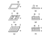
次に、本発明の第2の実施の形態による液晶表示装置について図8乃至図14を用いて説明する。図8は本実施の形態による液晶表示装置のB画素(青色のCF樹脂層が形成された画素)の構成を示し、図9は本実施の形態による液晶表示装置のR画素又はG画素(赤色又は緑色のCF樹脂層が形成された画素)の構成を示している。図10(a)は図8のD−D線で切断した液晶表示装置の断面構成を示し、図10(b)は図9のE−E線で切断した液晶表示装置の断面構成を示している。図11はTFT基板2と貼り合わせる前の対向基板4の断面構成を示している。図11(a)は図10(a)と同位置で切断した対向基板4の断面構成を示し、図11(b)は図10(b)と同位置で切断した対向基板4の断面構成を示している。図12は対向基板4と貼り合わせる前のTFT基板2の断面構成を示している。図12(a)は図10(a)と同位置で切断したTFT基板2の断面構成を示し、図12(b)は図10(b)と同位置で切断したTFT基板2の断面構成を示している。
[Second Embodiment]
Next, a liquid crystal display device according to a second embodiment of the present invention will be described with reference to FIGS. FIG. 8 shows a configuration of a B pixel (a pixel on which a blue CF resin layer is formed) of the liquid crystal display device according to the present embodiment, and FIG. 9 shows an R pixel or a G pixel (red color) of the liquid crystal display device according to the present embodiment. Or the structure of the pixel in which the green CF resin layer was formed is shown. 10A shows a cross-sectional configuration of the liquid crystal display device cut along line DD in FIG. 8, and FIG. 10B shows a cross-sectional configuration of the liquid crystal display device cut along line EE in FIG. Yes. FIG. 11 shows a cross-sectional configuration of the
図8乃至図12(a)、(b)に示すように、本実施の形態においては、B画素とR画素及びG画素とではTFT基板2側の構成が互いに異なっている。TFT基板2のB画素は、図2とほぼ同様の構成を有している。B画素の対向基板4側には、接続部33bと蓄積容量電極19とがT字状に交わる領域に、例えばアクリル樹脂系ネガ型感光性レジストからなる柱状スペーサ45が形成されている。柱状スペーサ45の形成領域と画素開口部とのTFT基板2側の構成を比較すると、柱状スペーサ45の形成領域は、TFT20のゲート電極23と同層に形成された蓄積容量バスライン18と、動作半導体層28と同層に形成されたa−Si層62と、オーミックコンタクト層29と同層に形成されたn+a−Si層61と、ソース電極22及びドレイン電極21と同層に形成された接続部33b(蓄積容量電極19)とを有している。これにより、柱状スペーサ45の形成領域には、高さT1の凸部63が形成される。柱状スペーサ45及び凸部63は、第1のセルギャップ維持用構造物を構成する。第1のセルギャップ維持用構造物は、対向基板4及びTFT基板2の双方に接触し、セルギャップG1を維持している。
As shown in FIGS. 8 to 12A and 12B, in the present embodiment, the configuration of the
R画素及びG画素の対向基板4には、柱状スペーサ45と同一層の柱状スペーサ46が形成されている。B画素の構成と異なり、R画素及びG画素の接続部33b及び蓄積容量電極19は、柱状スペーサ46の形成領域を迂回するように配置されている。したがって、柱状スペーサ46の形成領域は蓄積容量バスライン18を有しているが、柱状スペーサ45の形成領域と比較すると、a−Si層62、n+a−Si層61及び接続部33bを有していない。これにより、柱状スペーサ46の形成領域には、a−Si層62、n+a−Si層61及び接続部33bの各膜厚の総和分だけ凸部63より低い高さT2の凸部64が形成される(T1>T2)。本例では、高さT1と高さT2との差(T1−T2)は例えば0.50μmである。柱状スペーサ46及び凸部64は、第2のセルギャップ維持用構造物を構成する。基板貼合せ前には、柱状スペーサ45の共通電極41からの高さC1と柱状スペーサ46の共通電極41からの高さC2とはほぼ同一であり(C1=C2)、例えば共に3.2μmである。
A
本実施の形態による液晶表示装置は滴下注入(ODF)法を用いて作製されており、基板2、4間の外周部には液晶を封止するために切れ目なく塗布されたシール材が形成されている。ODF法を用いて作製される液晶表示装置のセルギャップG1は、滴下される液晶量により決まる。本実施の形態では、基板2、4間のセルギャップG1が(T1+C1)<G1<(T2+C2)の関係を満たすような液晶量が滴下される。したがって、柱状スペーサ45と凸部63は互いに接触し、(G1−(T2+C2))(例えば0.25μm)だけ圧縮される。一方、柱状スペーサ46と凸部64とは互いに接触せず、(G1−(T1+C1))(例えば0.25μm)の間隙を介して対向する。すなわち、柱状スペーサ45及び凸部63を備えた第1のセルギャップ維持用構造物は、常時セルギャップG1を維持し、柱状スペーサ46及び凸部64を備えた第2のセルギャップ維持用構造物は、外部から加圧されたときにセルギャップG1より狭いセルギャップG2(図示せず)を維持するようになっている。
The liquid crystal display device according to the present embodiment is manufactured using a drop injection (ODF) method, and a sealing material that is applied without breaks is formed on the outer periphery between the
柱状スペーサ45の上底面積(第1のセルギャップ維持用構造物の支持面積)S1と柱状スペーサ46の上底面積(第2のセルギャップ維持用構造物の支持面積)S2とはほぼ同一であり(S1=S2)、例えば共に300μm2である。柱状スペーサ45は5つのB画素に1つ配置され、柱状スペーサ46は全R画素及び全G画素に配置されている。したがって、第1のセルギャップ維持用構造物の面積密度D1は、第2のセルギャップ維持用構造物の面積密度D2の1/10になっている(D1:D2=1:10)。なお、柱状スペーサ45が形成されないB画素のTFT基板2側の構成は、R画素及びG画素のTFT基板2側の構成と同様であってもよい。
The upper base area (support area of the first cell gap maintaining structure) S1 of the
例えば製造ばらつきにより柱状スペーサ45が0.15μm低く形成された場合であっても、基板貼合せ後には柱状スペーサ45(及び凸部63)は0.10μmだけ圧縮されることになる。したがって、作製した液晶表示パネルは重力むらの発生しない内部圧力を有する。一方、柱状スペーサ46が0.15μm高く形成された場合であっても、基板貼合せ後には柱状スペーサ46と凸部64の間には0.10μmの間隙が存在するため、常温時に互いに接触しないことになる。したがって、低温下での気泡の発生を防止できる。
For example, even when the
また、液晶表示パネルの基板2、4間に外部から高い圧力が加えられたときには、第1のセルギャップ維持用構造物に加えて第2のセルギャップ維持用構造物もセルギャップを維持する。したがって、セルギャップむらが生じず、外部からの加圧に対する高い耐性が得られる。
When a high pressure is applied from the outside between the
本実施の形態によれば第1の実施の形態と同様の効果が得られるだけでなく、外部から圧力が加えられていないときには低い面積密度D1で形成された第1のセルギャップ維持用構造物だけがセルギャップG1を維持しているため、低温下での気泡の発生を防止できる。一方、外部から圧力が加えられたときには高い面積密度(D1+D2)で形成された第1及び第2のセルギャップ維持用構造物がセルギャップG2を維持するため、セルギャップむらを抑制できる。また、本実施の形態によれば、ODF法を用いて作製される液晶表示装置において、広い製造マージン及び高い耐加圧性という相反する2つの効果を同時に実現できる。 According to the present embodiment, not only the same effect as the first embodiment can be obtained, but also the first cell gap maintaining structure formed with a low area density D1 when no pressure is applied from the outside. Since only the cell gap G1 is maintained, the generation of bubbles at a low temperature can be prevented. On the other hand, when pressure is applied from the outside, the first and second cell gap maintaining structures formed with a high area density (D1 + D2) maintain the cell gap G2, so that cell gap unevenness can be suppressed. Further, according to the present embodiment, in a liquid crystal display device manufactured using the ODF method, two conflicting effects of a wide manufacturing margin and high pressure resistance can be realized at the same time.
次に、本実施の形態による液晶表示装置の製造方法について簡単に説明する。図13は、対向基板4の製造工程を示している。まず、図13(a)に示すように、ガラス基板11等の絶縁性基板上にCr金属又は樹脂ブラックを用いてBM48を形成する。次に、図13(b)に示すように、顔料分散型感光性着色樹脂等を用いてCF樹脂層40R、40G、40Bを順次形成する。次に、図13(c)に示すように、ITO等の透明導電膜をスパッタリングして共通電極41を形成する。次に、図13(d)に示すように、例えばノボラック樹脂系ポジ型感光性レジストを基板全面に塗布し、フォトリソグラフィ法を用いて所定の配置パターンの線状突起42を形成する。次に、図13(e)に示すように、例えばアクリル樹脂系ネガ型感光性レジストを基板全面に塗布し、フォトリソグラフィ法を用いて所定の位置に所定の上底面積を有する柱状スペーサ45、46を形成する。柱状スペーサ45は例えば5つのB画素に1つの配置密度で配置され、柱状スペーサ46は全R画素及び全G画素に1つずつの配置密度で配置される。以上の工程を経て、対向基板4が作製される。
Next, a method for manufacturing the liquid crystal display device according to the present embodiment will be briefly described. FIG. 13 shows a manufacturing process of the
図14は、ODF法を用いた液晶表示パネルの製造工程を示す図である。図14(a)、(c)、(e)は各工程での対向基板4の状態を示す斜視図であり、図14(b)、(d)、(f)は各工程での柱状スペーサ45(又は46)近傍の状態を示す概略断面図である。まず対向基板4及び別工程で作製されたTFT基板2の表面に配向膜を形成し、図14(a)、(b)に示すように、例えば対向基板4の外周部の全周に、光硬化型のシール材60を切れ目なく塗布する。次に、図14(c)、(d)に示すように、対向基板4上に所定量の液晶6を滴下する。なお図14(d)では、滴下された状態の液晶6ではなく、後述する工程で充填された状態の液晶6を示している。次に、図14(e)、(f)に示すように、対向基板4とTFT基板2とを真空中で貼り合わせ、大気圧に戻すことにより液晶6を基板2、4間に充填する。このとき、セルギャップは液晶6の滴下量により制御され、柱状スペーサ45はTFT基板2に接触して所定の変位量だけ圧縮される。シール材60を硬化させた後、パネル切断、偏光板貼付け等の工程を経て液晶表示パネルが完成する。その後、モジュール工程等を経て液晶表示装置が完成する。
FIG. 14 is a diagram showing a manufacturing process of a liquid crystal display panel using the ODF method. 14A, 14C, and 14E are perspective views showing the state of the
本発明は、上記実施の形態に限らず種々の変形が可能である。
例えば、上記実施の形態では透過型の液晶表示装置を例に挙げたが、本発明はこれに限らず、反射型や半透過型等の他の液晶表示装置にも適用できる。
The present invention is not limited to the above embodiment, and various modifications can be made.
For example, although the transmissive liquid crystal display device has been described as an example in the above embodiment, the present invention is not limited to this and can be applied to other liquid crystal display devices such as a reflective type and a transflective type.
また上記実施の形態では、2つの副画素を備えた画素領域を有する液晶表示装置を例に挙げたが、本発明はこれに限らず、3つ又はそれ以上の副画素を備えた画素領域を有する液晶表示装置にも適用できる。 In the above embodiment, a liquid crystal display device having a pixel region including two sub-pixels is taken as an example. However, the present invention is not limited to this, and a pixel region including three or more sub-pixels is used. The present invention can also be applied to a liquid crystal display device having the same.
さらに上記実施の形態では、チャネルエッチ型のTFTを備えた液晶表示装置を例に挙げたが、本発明はこれに限らず、チャネル保護膜型のTFTを備えた液晶表示装置にも適用できる。 Further, in the above embodiment, a liquid crystal display device including a channel etch type TFT is taken as an example, but the present invention is not limited to this, and can be applied to a liquid crystal display device including a channel protective film type TFT.
以上説明した実施の形態による液晶表示装置は、以下のようにまとめられる。
(付記1)
対向配置された一対の基板と、
前記一対の基板間に封止された液晶と、
一方の前記基板上に形成された第1の画素電極と、前記一方の基板上に形成され、前記第1の画素電極から分離された第2の画素電極とをそれぞれ備えた複数の画素領域と、
前記画素領域毎に配置され、前記第1の画素電極に電気的に接続されたソース電極を備えたトランジスタと、
他方の前記基板上に形成され、前記液晶を配向規制する線状の配向規制用構造物と、
前記ソース電極に電気的に接続され、絶縁膜を介して前記第2の画素電極の少なくとも一部に対向し、基板面に垂直に見て少なくとも一部が前記配向規制用構造物に重なって配置されかつ前記配向規制用構造物に沿って延びる制御容量電極を備え、前記ソース電極と前記第2の画素電極とを容量結合する制御容量部と
を有することを特徴とする液晶表示装置。
(付記2)
付記1記載の液晶表示装置において、
前記制御容量電極の幅は、前記配向規制用構造物の幅よりも狭いこと
を特徴とする液晶表示装置。
(付記3)
付記1又は2に記載の液晶表示装置において、
前記画素領域端部を遮光する遮光膜をさらに有し、
前記制御容量電極は、基板面に垂直に見て少なくとも一部が前記遮光膜に重なって配置されていること
を特徴とする液晶表示装置。
(付記4)
付記1乃至3のいずれか1項に記載の液晶表示装置において、
前記画素領域は、長さXの短辺と長さ約3Xの長辺とを有する長方形状であり、
前記配向規制用構造物は、一方の前記長辺の両端に位置する2つの前記画素領域角部をそれぞれ通り、前記長辺に対し約45°の角度をなす方向であって互いにほぼ垂直な方向にそれぞれ直線状に延伸する2つの領域を前記画素領域内に有していること
を特徴とする液晶表示装置。
(付記5)
付記4記載の液晶表示装置において、
前記制御容量電極は、前記配向規制用構造物の前記2つの領域にそれぞれ沿って延伸する2つの斜め延伸部と、他方の前記長辺に沿って延伸し、前記2つの斜め延伸部間を接続する長さ約Xの接続部とを有すること
を特徴とする液晶表示装置。
(付記6)
付記5記載の液晶表示装置において、
前記配向規制用構造物の幅をYとし、前記接続部の幅をZとしたとき、
前記制御電極の前記第2の画素電極に対する重なり面積Sは、
S≦(Y×√(X2+X2)−Y2/2)×2+X×Z
の関係を満たすこと
を特徴とする液晶表示装置。
(付記7)
付記6記載の液晶表示装置において、
前記絶縁膜はシリコン窒化膜からなり、100nm以上300nm以下の膜厚を有すること
を特徴とする液晶表示装置。
(付記8)
付記6又は7に記載の液晶表示装置において、
前記配向規制用構造物の幅Yは8μm以上12μm以下であること
を特徴とする液晶表示装置。
(付記9)
付記6乃至8のいずれか1項に記載の液晶表示装置において、
前記接続部の幅Zは2μm以上15μm以下であること
を特徴とする液晶表示装置。
(付記10)
付記1乃至9のいずれか1項に記載の液晶表示装置において、
前記一対の基板間の外周部に切れ目なく塗布され、前記液晶を封止するシール材と、
前記一対の基板の双方に接触し、第1のセルギャップを維持する第1のセルギャップ維持用構造物と、
外部から加圧されたときに前記第1のセルギャップより狭い第2のセルギャップを維持する第2のセルギャップ維持用構造物とをさらに有すること
を特徴とする液晶表示装置。
(付記11)
付記10記載の液晶表示装置において、
前記第1のセルギャップ維持用構造物は、前記トランジスタのゲート電極と同層に形成された第1層と、前記ソース電極と同層に形成された第2層とを共に有し、
前記第2のセルギャップ維持用構造物は、前記第1層又は前記第2層のいずれか一方を有すること
を特徴とする液晶表示装置。
The liquid crystal display device according to the embodiment described above can be summarized as follows.
(Appendix 1)
A pair of opposed substrates;
Liquid crystal sealed between the pair of substrates;
A plurality of pixel regions each including a first pixel electrode formed on one of the substrates and a second pixel electrode formed on the one substrate and separated from the first pixel electrode; ,
A transistor including a source electrode disposed in each pixel region and electrically connected to the first pixel electrode;
A linear alignment regulating structure which is formed on the other substrate and regulates the alignment of the liquid crystal;
It is electrically connected to the source electrode, faces at least a part of the second pixel electrode through an insulating film, and is arranged so that at least a part thereof overlaps the alignment regulating structure when viewed perpendicular to the substrate surface. A liquid crystal display device comprising: a control capacitor electrode including a control capacitor electrode extending along the alignment regulating structure, and capacitively coupling the source electrode and the second pixel electrode.
(Appendix 2)
In the liquid crystal display device according to
A width of the control capacitor electrode is narrower than a width of the alignment regulating structure.
(Appendix 3)
In the liquid crystal display device according to
A light-shielding film that shields light from the pixel region end;
The liquid crystal display device, wherein the control capacitor electrode is disposed so that at least a part thereof overlaps the light shielding film when viewed perpendicularly to a substrate surface.
(Appendix 4)
In the liquid crystal display device according to any one of
The pixel region has a rectangular shape having a short side with a length X and a long side with a length of about 3X,
The alignment regulating structure passes through the two pixel region corners located at both ends of one of the long sides, and forms a direction of about 45 ° with respect to the long side and is substantially perpendicular to each other. The liquid crystal display device is characterized in that each of the pixel regions has two regions extending linearly.
(Appendix 5)
In the liquid crystal display device according to
The control capacitor electrode extends along two other elongated sides extending along the two regions of the alignment regulating structure, and extends along the other long side, and connects the two obliquely extended portions. And a connection portion having a length of about X.
(Appendix 6)
In the liquid crystal display device according to
When the width of the alignment regulating structure is Y and the width of the connecting portion is Z,
The overlapping area S of the control electrode with respect to the second pixel electrode is:
S ≦ (Y × √ (X 2 + X 2) -
A liquid crystal display device characterized by satisfying the above relationship.
(Appendix 7)
In the liquid crystal display device according to
The liquid crystal display device, wherein the insulating film is made of a silicon nitride film and has a thickness of 100 nm to 300 nm.
(Appendix 8)
In the liquid crystal display device according to
The alignment control structure has a width Y of 8 μm or more and 12 μm or less.
(Appendix 9)
In the liquid crystal display device according to any one of
The liquid crystal display device, wherein a width Z of the connecting portion is 2 μm or more and 15 μm or less.
(Appendix 10)
The liquid crystal display device according to any one of
A sealing material that is applied to the outer peripheral portion between the pair of substrates without any break and seals the liquid crystal;
A first cell gap maintaining structure that contacts both of the pair of substrates and maintains the first cell gap;
A liquid crystal display device, further comprising: a second cell gap maintaining structure that maintains a second cell gap narrower than the first cell gap when pressurized from the outside.
(Appendix 11)
In the liquid crystal display device according to
The first cell gap maintaining structure has both a first layer formed in the same layer as the gate electrode of the transistor and a second layer formed in the same layer as the source electrode,
The second cell gap maintaining structure includes either the first layer or the second layer.
2 TFT基板
4 対向基板
6 液晶
10、11 ガラス基板
12 ゲートバスライン
14 ドレインバスライン
16a、16b 画素電極
18 蓄積容量バスライン
19 蓄積容量電極
20 TFT
21 ドレイン電極
22 ソース電極
23 ゲート電極
25 コンタクトホール
28 動作半導体層
29 オーミックコンタクト層
30 絶縁膜
31 保護膜
33 制御容量電極
33a、33c 斜め延伸部
33b 接続部
40、40R、40G、40B CF樹脂層
41 共通電極
42 線状突起
44、47 スリット
45、46 柱状スペーサ
48 BM
48a 開口部
50、51 垂直配向膜
60 シール材
61 n+a−Si層
62 a−Si層
63、64 凸部
80 ゲートバスライン駆動回路
82 ドレインバスライン駆動回路
84 制御回路
86、87 偏光板
88 バックライトユニット
2
21
Claims (11)
前記一対の基板間に封止された液晶と、
一方の前記基板上に形成された第1の画素電極と、前記一方の基板上に形成され、前記第1の画素電極から分離された第2の画素電極とをそれぞれ備えた複数の画素領域と、
前記画素領域毎に配置され、前記第1の画素電極に電気的に接続されたソース電極を備えたトランジスタと、
他方の前記基板上に形成され、前記液晶を配向規制する線状の配向規制用構造物と、
前記第1の画素電極を通らない電気的接続経路を介して前記ソース電極に電気的に接続され、絶縁膜を介して前記第2の画素電極の少なくとも一部に対向し、基板面に垂直に見て少なくとも一部が前記配向規制用構造物に重なって配置されかつ前記配向規制用構造物に沿って延びる制御容量電極を備え、前記ソース電極と前記第2の画素電極とを容量結合する制御容量部と
を有することを特徴とする液晶表示装置。 A pair of opposed substrates;
Liquid crystal sealed between the pair of substrates;
A plurality of pixel regions each including a first pixel electrode formed on one of the substrates and a second pixel electrode formed on the one substrate and separated from the first pixel electrode; ,
A transistor including a source electrode disposed in each pixel region and electrically connected to the first pixel electrode;
A linear alignment regulating structure which is formed on the other substrate and regulates the alignment of the liquid crystal;
The first does not pass through the pixel electrode via an electrical connection path is connected to the electrical to the source electrode through the insulating film to face at least a portion of the second pixel electrode, perpendicular to the substrate surface And a control capacitor electrode that is disposed so as to at least partially overlap the alignment regulating structure and extends along the alignment regulating structure, and capacitively couples the source electrode and the second pixel electrode. A liquid crystal display device comprising: a control capacitance unit.
前記制御容量電極の幅は、前記配向規制用構造物の幅よりも狭いこと
を特徴とする液晶表示装置。 The liquid crystal display device according to claim 1.
A width of the control capacitor electrode is narrower than a width of the alignment regulating structure.
前記画素領域端部を遮光する遮光膜をさらに有し、
前記制御容量電極は、基板面に垂直に見て少なくとも一部が前記遮光膜に重なって配置されていること
を特徴とする液晶表示装置。 The liquid crystal display device according to claim 1 or 2,
A light-shielding film that shields light from the pixel region end;
The liquid crystal display device, wherein the control capacitor electrode is disposed so that at least a part thereof overlaps the light shielding film when viewed perpendicularly to a substrate surface.
前記画素領域は、長さXの短辺と長さ約3Xの長辺とを有する長方形状であり、
前記配向規制用構造物は、一方の前記長辺の両端に位置する2つの前記画素領域角部をそれぞれ通り、前記長辺に対し約45°の角度をなす方向であって互いにほぼ垂直な方向にそれぞれ直線状に延伸する2つの領域を前記画素領域内に有していること
を特徴とする液晶表示装置。 The liquid crystal display device according to any one of claims 1 to 3,
The pixel region has a rectangular shape having a short side with a length X and a long side with a length of about 3X,
The alignment regulating structure passes through the two pixel region corners located at both ends of one of the long sides, and forms a direction of about 45 ° with respect to the long side and is substantially perpendicular to each other. The liquid crystal display device is characterized in that each of the pixel regions has two regions extending linearly.
前記制御容量電極は、前記配向規制用構造物の前記2つの領域にそれぞれ沿って延伸する2つの斜め延伸部と、他方の前記長辺に沿って延伸し、前記2つの斜め延伸部間を接続する長さ約Xの接続部とを有すること
を特徴とする液晶表示装置。 The liquid crystal display device according to claim 4.
The control capacitor electrode extends along two other elongated sides extending along the two regions of the alignment regulating structure, and extends along the other long side, and connects the two obliquely extended portions. And a connection portion having a length of about X.
前記配向規制用構造物の幅をYとし、前記接続部の幅をZとしたとき、
前記制御電極の前記第2の画素電極に対する重なり面積Sは、
S≦(Y×√(X2+X2)−Y2/2)×2+X×Z
の関係を満たすこと
を特徴とする液晶表示装置。 The liquid crystal display device according to claim 5.
When the width of the alignment regulating structure is Y and the width of the connecting portion is Z,
The overlapping area S of the control electrode with respect to the second pixel electrode is:
S ≦ (Y × √ (X2 + X2) −Y2 / 2) × 2 + X × Z
A liquid crystal display device characterized by satisfying the above relationship.
前記絶縁膜はシリコン窒化膜からなり、100nm以上300nm以下の膜厚を有すること
を特徴とする液晶表示装置。 The liquid crystal display device according to claim 6.
The liquid crystal display device, wherein the insulating film is made of a silicon nitride film and has a thickness of 100 nm to 300 nm.
前記配向規制用構造物の幅Yは8μm以上12μm以下であること
を特徴とする液晶表示装置。 The liquid crystal display device according to claim 6 or 7,
The alignment control structure has a width Y of 8 μm or more and 12 μm or less.
前記接続部の幅Zは2μm以上15μm以下であること
を特徴とする液晶表示装置。 The liquid crystal display device according to any one of claims 6 to 8,
The liquid crystal display device, wherein a width Z of the connecting portion is 2 μm or more and 15 μm or less.
前記一対の基板間の外周部に切れ目なく塗布され、前記液晶を封止するシール材と、
前記一対の基板の双方に接触し、第1のセルギャップを維持する第1のセルギャップ維持用構造物と、
外部から加圧されたときに前記第1のセルギャップより狭い第2のセルギャップを維持する第2のセルギャップ維持用構造物とをさらに有すること
を特徴とする液晶表示装置。 The liquid crystal display device according to any one of claims 1 to 9,
A sealing material that is applied to the outer peripheral portion between the pair of substrates without any break and seals the liquid crystal;
A first cell gap maintaining structure that contacts both of the pair of substrates and maintains the first cell gap;
A liquid crystal display device, further comprising: a second cell gap maintaining structure that maintains a second cell gap narrower than the first cell gap when pressurized from the outside.
前記配向規制用構造物は、前記他方の基板上に形成された共通電極を部分的に除去したスリットであること
を特徴とする液晶表示装置。 The liquid crystal display device according to any one of claims 1 to 10,
The liquid crystal display device, wherein the alignment regulating structure is a slit obtained by partially removing a common electrode formed on the other substrate.
Priority Applications (6)
| Application Number | Priority Date | Filing Date | Title |
|---|---|---|---|
| JP2005011519A JP4628801B2 (en) | 2005-01-19 | 2005-01-19 | Liquid crystal display device |
| KR1020060005353A KR100781477B1 (en) | 2005-01-19 | 2006-01-18 | Liquid crystal display device |
| US11/333,548 US7471348B2 (en) | 2005-01-19 | 2006-01-18 | Liquid crystal display device with control capacitance section |
| TW095102075A TWI331689B (en) | 2005-01-19 | 2006-01-19 | Liquid crystal display device |
| US12/314,974 US7911549B2 (en) | 2005-01-19 | 2008-12-19 | Liquid crystal display device |
| US13/024,765 US8035764B2 (en) | 2005-01-19 | 2011-02-10 | Liquid crystal display device |
Applications Claiming Priority (1)
| Application Number | Priority Date | Filing Date | Title |
|---|---|---|---|
| JP2005011519A JP4628801B2 (en) | 2005-01-19 | 2005-01-19 | Liquid crystal display device |
Related Child Applications (1)
| Application Number | Title | Priority Date | Filing Date |
|---|---|---|---|
| JP2010158119A Division JP4629161B2 (en) | 2010-07-12 | 2010-07-12 | Liquid crystal display device |
Publications (2)
| Publication Number | Publication Date |
|---|---|
| JP2006201356A JP2006201356A (en) | 2006-08-03 |
| JP4628801B2 true JP4628801B2 (en) | 2011-02-09 |
Family
ID=36959429
Family Applications (1)
| Application Number | Title | Priority Date | Filing Date |
|---|---|---|---|
| JP2005011519A Expired - Fee Related JP4628801B2 (en) | 2005-01-19 | 2005-01-19 | Liquid crystal display device |
Country Status (4)
| Country | Link |
|---|---|
| US (3) | US7471348B2 (en) |
| JP (1) | JP4628801B2 (en) |
| KR (1) | KR100781477B1 (en) |
| TW (1) | TWI331689B (en) |
Families Citing this family (13)
| Publication number | Priority date | Publication date | Assignee | Title |
|---|---|---|---|---|
| JP4628801B2 (en) * | 2005-01-19 | 2011-02-09 | シャープ株式会社 | Liquid crystal display device |
| KR101137842B1 (en) | 2005-09-23 | 2012-04-20 | 엘지디스플레이 주식회사 | Liquid Crystal Display Device and Method for Manufacturing the Same |
| JP4179393B2 (en) * | 2006-09-14 | 2008-11-12 | エプソンイメージングデバイス株式会社 | Display device and manufacturing method thereof |
| CN101568876B (en) * | 2007-01-17 | 2011-09-28 | 夏普株式会社 | Liquid crystal display panel, and liquid crystal display device |
| US7683991B2 (en) * | 2007-03-29 | 2010-03-23 | Tpo Displays Corp. | Multi-domain pixel structure in a system for displaying images |
| JP2009036937A (en) * | 2007-08-01 | 2009-02-19 | Hitachi Displays Ltd | Liquid crystal display and manufacturing method therefor |
| WO2009069368A1 (en) * | 2007-11-29 | 2009-06-04 | Sharp Kabushiki Kaisha | Display device and method of driving the display device |
| US20100265441A1 (en) * | 2007-12-18 | 2010-10-21 | Koki Hongo | Liquid crystal display device |
| EP2241933A4 (en) * | 2008-02-15 | 2011-11-16 | Sharp Kk | Liquid crystal display device |
| CN102209929B (en) * | 2008-11-19 | 2014-09-17 | 夏普株式会社 | Active matrix substrate, liquid crystal display panel, liquid crystal display device, method for manufacturing active matrix substrate, method for manufacturing liquid crystal display panel and method for driving liquid crystal display panel |
| KR101612480B1 (en) | 2008-12-22 | 2016-04-27 | 삼성디스플레이 주식회사 | Alignment substrate for aligning liquid crystal molecules, liquid crystal display panel having the same and method of manufacturing the alignment substrate |
| US20120105418A1 (en) * | 2009-07-15 | 2012-05-03 | Sharp Kabushiki Kaisha | Liquid crystal display device |
| US9846340B1 (en) * | 2016-06-15 | 2017-12-19 | A.U. Vista, Inc. | Pixel structure utilizing photo spacer stage design and display device having the same |
Citations (2)
| Publication number | Priority date | Publication date | Assignee | Title |
|---|---|---|---|---|
| JP2005004212A (en) * | 2003-06-10 | 2005-01-06 | Samsung Electronics Co Ltd | Multidomain liquid crystal display device and display plate used therein |
| JP2005055896A (en) * | 2003-08-04 | 2005-03-03 | Samsung Electronics Co Ltd | Thin film transistor display board |
Family Cites Families (13)
| Publication number | Priority date | Publication date | Assignee | Title |
|---|---|---|---|---|
| US4840460A (en) | 1987-11-13 | 1989-06-20 | Honeywell Inc. | Apparatus and method for providing a gray scale capability in a liquid crystal display unit |
| EP0475117B1 (en) * | 1990-08-17 | 1996-11-20 | Dainippon Ink And Chemicals, Inc. | Liquid crystal device and process for producing the same |
| US5126865A (en) | 1990-12-31 | 1992-06-30 | Honeywell Inc. | Liquid crystal display with sub-pixels |
| JP3401049B2 (en) * | 1993-05-26 | 2003-04-28 | コーニンクレッカ フィリップス エレクトロニクス エヌ ヴィ | Gradation liquid crystal display panel |
| JPH0980396A (en) | 1995-09-12 | 1997-03-28 | Dainippon Ink & Chem Inc | Production of liquid crystal device |
| US6122032A (en) * | 1996-07-31 | 2000-09-19 | Canon Kabushiki Kaisha | Wedge shaped LCD with change in dispersion density of spacers |
| JP4081643B2 (en) | 2001-08-01 | 2008-04-30 | 株式会社日立製作所 | Liquid crystal display |
| TW588171B (en) * | 2001-10-12 | 2004-05-21 | Fujitsu Display Tech | Liquid crystal display device |
| JP3917417B2 (en) * | 2001-12-11 | 2007-05-23 | シャープ株式会社 | Reflective liquid crystal display |
| TW594310B (en) * | 2003-05-12 | 2004-06-21 | Hannstar Display Corp | Transflective LCD with single cell gap and the fabrication method thereof |
| US7206048B2 (en) * | 2003-08-13 | 2007-04-17 | Samsung Electronics Co., Ltd. | Liquid crystal display and panel therefor |
| TWI338796B (en) * | 2004-10-29 | 2011-03-11 | Chimei Innolux Corp | Multi-domain vertically alignmentliquid crystal display panel |
| JP4628801B2 (en) * | 2005-01-19 | 2011-02-09 | シャープ株式会社 | Liquid crystal display device |
-
2005
- 2005-01-19 JP JP2005011519A patent/JP4628801B2/en not_active Expired - Fee Related
-
2006
- 2006-01-18 KR KR1020060005353A patent/KR100781477B1/en not_active IP Right Cessation
- 2006-01-18 US US11/333,548 patent/US7471348B2/en active Active
- 2006-01-19 TW TW095102075A patent/TWI331689B/en not_active IP Right Cessation
-
2008
- 2008-12-19 US US12/314,974 patent/US7911549B2/en not_active Expired - Fee Related
-
2011
- 2011-02-10 US US13/024,765 patent/US8035764B2/en not_active Expired - Fee Related
Patent Citations (2)
| Publication number | Priority date | Publication date | Assignee | Title |
|---|---|---|---|---|
| JP2005004212A (en) * | 2003-06-10 | 2005-01-06 | Samsung Electronics Co Ltd | Multidomain liquid crystal display device and display plate used therein |
| JP2005055896A (en) * | 2003-08-04 | 2005-03-03 | Samsung Electronics Co Ltd | Thin film transistor display board |
Also Published As
| Publication number | Publication date |
|---|---|
| TW200638097A (en) | 2006-11-01 |
| US20070211187A1 (en) | 2007-09-13 |
| KR100781477B1 (en) | 2007-12-03 |
| US20110194042A1 (en) | 2011-08-11 |
| US20090122245A1 (en) | 2009-05-14 |
| KR20060084383A (en) | 2006-07-24 |
| TWI331689B (en) | 2010-10-11 |
| US8035764B2 (en) | 2011-10-11 |
| US7911549B2 (en) | 2011-03-22 |
| JP2006201356A (en) | 2006-08-03 |
| US7471348B2 (en) | 2008-12-30 |
Similar Documents
| Publication | Publication Date | Title |
|---|---|---|
| KR100781477B1 (en) | Liquid crystal display device | |
| US7474292B2 (en) | Liquid crystal display device | |
| JP4438665B2 (en) | Liquid crystal display | |
| JP4571845B2 (en) | Substrate for liquid crystal display device, liquid crystal display device including the same, and driving method thereof | |
| JP4731206B2 (en) | Liquid crystal display | |
| JP4738000B2 (en) | Liquid crystal display | |
| US8441604B2 (en) | Liquid crystal display having circular shaped protrusions on the common electrode | |
| US7872700B2 (en) | Liquid crystal display and thin film transistor array panel therefor | |
| JP4628802B2 (en) | Liquid crystal display | |
| US20070040974A1 (en) | Liquid crystal display panel | |
| US20050200789A1 (en) | Liquid crystal display device | |
| US7499131B2 (en) | Liquid crystal display device with different alignments | |
| JP4447484B2 (en) | Liquid crystal display | |
| JP4629161B2 (en) | Liquid crystal display device | |
| JP4305551B2 (en) | Transflective liquid crystal device and electronic device using the same | |
| JP5154592B2 (en) | Liquid crystal display | |
| JP4629160B2 (en) | Liquid crystal display device | |
| JP2010210733A (en) | Liquid crystal display panel | |
| KR20050003264A (en) | Vertical alignment mode liquid crystal display panel and method of fabricating thereof |
Legal Events
| Date | Code | Title | Description |
|---|---|---|---|
| A621 | Written request for application examination |
Free format text: JAPANESE INTERMEDIATE CODE: A621 Effective date: 20070302 |
|
| A977 | Report on retrieval |
Free format text: JAPANESE INTERMEDIATE CODE: A971007 Effective date: 20090930 |
|
| A131 | Notification of reasons for refusal |
Free format text: JAPANESE INTERMEDIATE CODE: A131 Effective date: 20091208 |
|
| A521 | Written amendment |
Free format text: JAPANESE INTERMEDIATE CODE: A523 Effective date: 20100204 |
|
| A131 | Notification of reasons for refusal |
Free format text: JAPANESE INTERMEDIATE CODE: A131 Effective date: 20100511 |
|
| A521 | Written amendment |
Free format text: JAPANESE INTERMEDIATE CODE: A523 Effective date: 20100712 |
|
| TRDD | Decision of grant or rejection written | ||
| A01 | Written decision to grant a patent or to grant a registration (utility model) |
Free format text: JAPANESE INTERMEDIATE CODE: A01 Effective date: 20101109 |
|
| A01 | Written decision to grant a patent or to grant a registration (utility model) |
Free format text: JAPANESE INTERMEDIATE CODE: A01 |
|
| A61 | First payment of annual fees (during grant procedure) |
Free format text: JAPANESE INTERMEDIATE CODE: A61 Effective date: 20101110 |
|
| FPAY | Renewal fee payment (event date is renewal date of database) |
Free format text: PAYMENT UNTIL: 20131119 Year of fee payment: 3 |
|
| R150 | Certificate of patent or registration of utility model |
Ref document number: 4628801 Country of ref document: JP Free format text: JAPANESE INTERMEDIATE CODE: R150 Free format text: JAPANESE INTERMEDIATE CODE: R150 |
|
| LAPS | Cancellation because of no payment of annual fees |