JP2019058574A - Ultrasonic wave probe - Google Patents
Ultrasonic wave probe Download PDFInfo
- Publication number
- JP2019058574A JP2019058574A JP2017187485A JP2017187485A JP2019058574A JP 2019058574 A JP2019058574 A JP 2019058574A JP 2017187485 A JP2017187485 A JP 2017187485A JP 2017187485 A JP2017187485 A JP 2017187485A JP 2019058574 A JP2019058574 A JP 2019058574A
- Authority
- JP
- Japan
- Prior art keywords
- matching layer
- acoustic lens
- acoustic
- piezoelectric element
- light
- Prior art date
- Legal status (The legal status is an assumption and is not a legal conclusion. Google has not performed a legal analysis and makes no representation as to the accuracy of the status listed.)
- Pending
Links
Images


Classifications
-
- A—HUMAN NECESSITIES
- A61—MEDICAL OR VETERINARY SCIENCE; HYGIENE
- A61B—DIAGNOSIS; SURGERY; IDENTIFICATION
- A61B3/00—Apparatus for testing the eyes; Instruments for examining the eyes
- A61B3/10—Objective types, i.e. instruments for examining the eyes independent of the patients' perceptions or reactions
- A61B3/1005—Objective types, i.e. instruments for examining the eyes independent of the patients' perceptions or reactions for measuring distances inside the eye, e.g. thickness of the cornea
-
- A—HUMAN NECESSITIES
- A61—MEDICAL OR VETERINARY SCIENCE; HYGIENE
- A61B—DIAGNOSIS; SURGERY; IDENTIFICATION
- A61B8/00—Diagnosis using ultrasonic, sonic or infrasonic waves
- A61B8/44—Constructional features of the ultrasonic, sonic or infrasonic diagnostic device
- A61B8/4444—Constructional features of the ultrasonic, sonic or infrasonic diagnostic device related to the probe
-
- A—HUMAN NECESSITIES
- A61—MEDICAL OR VETERINARY SCIENCE; HYGIENE
- A61B—DIAGNOSIS; SURGERY; IDENTIFICATION
- A61B8/00—Diagnosis using ultrasonic, sonic or infrasonic waves
- A61B8/44—Constructional features of the ultrasonic, sonic or infrasonic diagnostic device
- A61B8/4483—Constructional features of the ultrasonic, sonic or infrasonic diagnostic device characterised by features of the ultrasound transducer
- A61B8/4494—Constructional features of the ultrasonic, sonic or infrasonic diagnostic device characterised by features of the ultrasound transducer characterised by the arrangement of the transducer elements
-
- A—HUMAN NECESSITIES
- A61—MEDICAL OR VETERINARY SCIENCE; HYGIENE
- A61B—DIAGNOSIS; SURGERY; IDENTIFICATION
- A61B3/00—Apparatus for testing the eyes; Instruments for examining the eyes
- A61B3/0008—Apparatus for testing the eyes; Instruments for examining the eyes provided with illuminating means
-
- A—HUMAN NECESSITIES
- A61—MEDICAL OR VETERINARY SCIENCE; HYGIENE
- A61B—DIAGNOSIS; SURGERY; IDENTIFICATION
- A61B8/00—Diagnosis using ultrasonic, sonic or infrasonic waves
- A61B8/10—Eye inspection
-
- A—HUMAN NECESSITIES
- A61—MEDICAL OR VETERINARY SCIENCE; HYGIENE
- A61B—DIAGNOSIS; SURGERY; IDENTIFICATION
- A61B8/00—Diagnosis using ultrasonic, sonic or infrasonic waves
- A61B8/42—Details of probe positioning or probe attachment to the patient
- A61B8/4272—Details of probe positioning or probe attachment to the patient involving the acoustic interface between the transducer and the tissue
- A61B8/4281—Details of probe positioning or probe attachment to the patient involving the acoustic interface between the transducer and the tissue characterised by sound-transmitting media or devices for coupling the transducer to the tissue
-
- A—HUMAN NECESSITIES
- A61—MEDICAL OR VETERINARY SCIENCE; HYGIENE
- A61B—DIAGNOSIS; SURGERY; IDENTIFICATION
- A61B8/00—Diagnosis using ultrasonic, sonic or infrasonic waves
- A61B8/44—Constructional features of the ultrasonic, sonic or infrasonic diagnostic device
- A61B8/4416—Constructional features of the ultrasonic, sonic or infrasonic diagnostic device related to combined acquisition of different diagnostic modalities, e.g. combination of ultrasound and X-ray acquisitions
-
- A—HUMAN NECESSITIES
- A61—MEDICAL OR VETERINARY SCIENCE; HYGIENE
- A61B—DIAGNOSIS; SURGERY; IDENTIFICATION
- A61B8/00—Diagnosis using ultrasonic, sonic or infrasonic waves
- A61B8/44—Constructional features of the ultrasonic, sonic or infrasonic diagnostic device
- A61B8/4483—Constructional features of the ultrasonic, sonic or infrasonic diagnostic device characterised by features of the ultrasound transducer
-
- G—PHYSICS
- G01—MEASURING; TESTING
- G01N—INVESTIGATING OR ANALYSING MATERIALS BY DETERMINING THEIR CHEMICAL OR PHYSICAL PROPERTIES
- G01N29/00—Investigating or analysing materials by the use of ultrasonic, sonic or infrasonic waves; Visualisation of the interior of objects by transmitting ultrasonic or sonic waves through the object
- G01N29/22—Details, e.g. general constructional or apparatus details
- G01N29/24—Probes
- G01N29/2437—Piezoelectric probes
-
- G—PHYSICS
- G01—MEASURING; TESTING
- G01N—INVESTIGATING OR ANALYSING MATERIALS BY DETERMINING THEIR CHEMICAL OR PHYSICAL PROPERTIES
- G01N29/00—Investigating or analysing materials by the use of ultrasonic, sonic or infrasonic waves; Visualisation of the interior of objects by transmitting ultrasonic or sonic waves through the object
- G01N29/22—Details, e.g. general constructional or apparatus details
- G01N29/28—Details, e.g. general constructional or apparatus details providing acoustic coupling, e.g. water
Landscapes
- Health & Medical Sciences (AREA)
- Life Sciences & Earth Sciences (AREA)
- Physics & Mathematics (AREA)
- General Health & Medical Sciences (AREA)
- Veterinary Medicine (AREA)
- Pathology (AREA)
- Biomedical Technology (AREA)
- Heart & Thoracic Surgery (AREA)
- Medical Informatics (AREA)
- Molecular Biology (AREA)
- Surgery (AREA)
- Animal Behavior & Ethology (AREA)
- Engineering & Computer Science (AREA)
- Public Health (AREA)
- Biophysics (AREA)
- Radiology & Medical Imaging (AREA)
- Nuclear Medicine, Radiotherapy & Molecular Imaging (AREA)
- Ophthalmology & Optometry (AREA)
- Gynecology & Obstetrics (AREA)
- General Physics & Mathematics (AREA)
- Immunology (AREA)
- Chemical & Material Sciences (AREA)
- Biochemistry (AREA)
- Analytical Chemistry (AREA)
- Acoustics & Sound (AREA)
- Transducers For Ultrasonic Waves (AREA)
- Ultra Sonic Daignosis Equipment (AREA)
- Eye Examination Apparatus (AREA)
Abstract
Description
本発明は、超音波探触子に関する。 The present invention relates to an ultrasound probe.
超音波診断装置の超音波の送受信部として、超音波探触子が広く用いられている(例えば下記特許文献1及び2等参照)。超音波探触子として、超音波を角膜表面に接触させ発信し、その反射波の伝搬時間から眼軸長(目の表面/角膜から目の奥/網膜までの長さ=目の球の直径)を計測するものがある。この眼軸長測定用の超音波探触子は、眼球に直接当てて使用される。したがって、超音波探触子を眼球に当てた際に、眼球の角膜等の保護や被検者の苦痛の緩和を図る必要がある。このため、眼球に当接する超音波探触子の当接面は、局所的な凹凸がなく滑らかに形成されることが好ましい。
An ultrasound probe is widely used as an ultrasound transmission / reception unit of an ultrasound diagnostic apparatus (see, for example,
下記特許文献3には、眼球の表面に損傷を与えることのない安全性を優位にした眼軸長測定用の超音波探触子として、圧電素子と音響整合層とからなる探触子本体を探触子ケースから突出させた構成が開示されている。この超音波探触子の構成において、圧電素子及び音響整合層は、いずれも凹状面を有する湾曲した形状となっている。また、音響整合層の前面を含む探触子本体の超音波送受信面には、ポリパラキシリレンを主原料とした保護膜が形成されている。また、下記特許文献3には、従来技術の一例として、探触子本体の背面側に発光ダイオードが設けられ、この発光ダイオードの光を光ファイバーを介して眼球に照射させながら超音波を送受信して測定を行う構成が開示されている。
In
ところで、医療用機器は、その安全性確保の観点から所定の耐電圧性を備えることが要求されている。また、超音波探触子は、被検者に対して当接して使用されるため、生体適合性を備えることも要求されている。さらに、超音波探触子の耐久性については、超音波探触子は消毒されるため、耐薬品性が求められている。したがって、例えば、医療用機器の一部である上記特許文献3において開示された構成の超音波探触子では、耐電圧性を確保するために、音響整合層を所定の厚さに形成したり、音響整合層の表面に保護膜を形成したりして対応する必要があった。また、上記特許文献3に開示された超音波探触子では、超音波を収束させるために、圧電素子及び音響整合層を所定曲率の曲面を有する湾曲した形状に形成する必要があった。このため、音響整合層の厚さを所望の薄い厚さに設定することや、圧電素子及び音響整合層を所望の形状に形成することができない場合があることから、超音波探触子の設計の自由度に制約が生じていた。また、上記した保護膜の成膜には比較的高いコストがかかるため、超音波探触子の製造コストの増加を招いていた。
Medical devices are required to have predetermined voltage resistance from the viewpoint of securing the safety. In addition, since the ultrasound probe is used in contact with a subject, it is also required to have biocompatibility. Furthermore, regarding the durability of the ultrasonic probe, chemical resistance is required because the ultrasonic probe is disinfected. Therefore, for example, in the ultrasonic probe of the configuration disclosed in the above-mentioned
さらに、眼球との当接面を介して眼球に光を照射させる構成の超音波探触子において、光ファイバーなどの導光部材が当接面まで設けられるものや、導光部材が例えば保護膜の手前など当接面付近まで設けられるものでは、導光部材の存在により当接面に段差や局所的凹凸が生じて当接面の滑らかさが阻害されないように、超音波探触子の部品を精度よく組み付けて製造する必要があった。 Furthermore, in the ultrasonic probe configured to irradiate light to the eyeball through the contact surface with the eyeball, a light guide member such as an optical fiber is provided up to the contact surface, or the light guide member is a protective film, for example. In the case where the contact surface is provided up to near the contact surface such as the front, the parts of the ultrasonic probe are made so that the contact surface is not hampered by a step or local unevenness due to the presence of the light guide member. It was necessary to assemble and manufacture precisely.
以上のような事情に鑑み、本発明は、超音波探触子に係る設計上の制約を軽減できるとともに、低コストで容易に製造することができ、当接面から光を照射する構成のものであっても当接面の滑らかさを容易に確保できる超音波探触子を提供することを目的とする。 In view of the circumstances as described above, the present invention can reduce design restrictions relating to an ultrasonic probe, can be easily manufactured at low cost, and is configured to irradiate light from the contact surface It is an object of the present invention to provide an ultrasonic probe capable of easily securing the smoothness of the contact surface.
本発明では、丸型の形状からなる超音波を発生する圧電素子と、超音波を集束させるための音響レンズと、被検体からの超音波の反射を小さくするための音響整合層と、を備え、圧電素子の中央に穴があり、その穴には光源の光を導光する光ファイバーが貫通し、光を照射しながら超音波を送受信する超音波探触子であって、音響レンズの材料に、耐電圧性のある樹脂、主として、ポリメチルペンテンを使用し、音響整合層には、耐電圧性を確保するためのポリパラキシリレンコーティングをしないことで音響整合層の厚さをλ/4とし、光ファイバーの先端が音響レンズを貫通しないように構成され、圧電素子と音響整合層の形状を平面状としたことを特徴とする。 In the present invention, a piezoelectric element configured to generate an ultrasonic wave having a circular shape, an acoustic lens for focusing the ultrasonic wave, and an acoustic matching layer for reducing reflection of the ultrasonic wave from the subject are provided. An ultrasonic probe which has a hole at the center of the piezoelectric element, through which an optical fiber for guiding the light of the light source penetrates and which transmits and receives an ultrasonic wave while emitting light, which is a material of an acoustic lens , Using a voltage resistant resin, mainly polymethylpentene, the acoustic matching layer does not have a polyparaxylylene coating to ensure the voltage resistance, and the thickness of the acoustic matching layer is λ / 4. The tip of the optical fiber is configured not to penetrate the acoustic lens, and the shape of the piezoelectric element and the acoustic matching layer is planar.
また、本発明では、丸型の形状からなる超音波を発生する圧電素子と、超音波を集束させるための音響レンズと、被検体からの超音波の反射を小さくするための音響整合層と、を備え、圧電素子の中央に穴があり、その穴には光源の光を導光する光ファイバーが貫通し、光を照射しながら超音波を送受信する超音波探触子であって、光ファイバーは、その先端が音響レンズを貫通しないように配置され、光ファイバーの先端の光が被検体に届くように音響レンズの色を透明又は半透明にし、かつ、音響レンズの形状を凹面状としたことを特徴とする。 Further, in the present invention, a piezoelectric element for generating an ultrasonic wave having a round shape, an acoustic lens for focusing the ultrasonic wave, and an acoustic matching layer for reducing reflection of the ultrasonic wave from the subject. An ultrasonic probe through which an optical fiber for guiding light of a light source penetrates and which transmits and receives an ultrasonic wave while emitting light, the optical fiber comprising: The tip is disposed so as not to penetrate the acoustic lens, the color of the acoustic lens is made transparent or semi-transparent so that the light at the tip of the optical fiber reaches the object, and the shape of the acoustic lens is concave. I assume.
さらに、本発明では、丸型の形状からなる超音波を発生する圧電素子と、超音波を集束させるための音響レンズと、被検体からの超音波の反射を小さくするための音響整合層と、を備え、圧電素子の中央に穴があり、その穴には光源の光を導光する光ファイバーが貫通し、光を照射しながら超音波を送受信する超音波探触子であって、音響レンズの材料として、耐電圧性のある樹脂、主として、ポリメチルペンテンを使用し、音響整合層の耐電圧性を確保するためのポリパラキシリレンコーティングを使用しないことで、音響整合層の厚さをλ/4とし、圧電素子と音響整合層の形状を平面状とし、光ファイバーは、その先端が音響レンズを貫通しないように配置され、光ファイバーの先端の光が被検体に届くように音響レンズを透明又は半透明にし、かつ、音響レンズの形状を凹面状としたことを特徴とする。 Furthermore, in the present invention, a piezoelectric element for generating an ultrasonic wave having a round shape, an acoustic lens for focusing the ultrasonic wave, and an acoustic matching layer for reducing reflection of the ultrasonic wave from the subject. An ultrasonic probe for transmitting and receiving an ultrasonic wave while emitting light through an optical fiber having a hole in the center of the piezoelectric element, through which light from the light source is guided. As the material, a voltage resistant resin, mainly polymethylpentene, is used, and the thickness of the acoustic matching layer is λ by using no polyparaxylylene coating for securing the voltage resistance of the acoustic matching layer. The shape of the piezoelectric element and the acoustic matching layer is planar, and the optical fiber is disposed so that its tip does not penetrate the acoustic lens, and the acoustic lens is transparent or light so that the light at the tip of the optical fiber reaches the object Translucent And the shape of the acoustic lens is concave.
本発明によれば、超音波探触子において、圧電素子や、音響整合層、保護膜などに係る設計上の制約を軽減することができる。また、本発明によれば、低コストでかつ容易に超音波探触子を製造することができる。さらに、本発明によれば、超音波探触子において、被検体との当接面を介して光を照射する機能を備えつつ、滑らかな当接面を容易に形成することができる。本発明の超音波探触子において、音響レンズに用いられているポリメチルペンテンは、ポリパラキシリレンと同様に、耐電圧性、生体適合性、及び耐薬品性を有する。 According to the present invention, in an ultrasonic probe, design restrictions relating to a piezoelectric element, an acoustic matching layer, a protective film and the like can be alleviated. Moreover, according to the present invention, an ultrasound probe can be manufactured easily at low cost. Furthermore, according to the present invention, in the ultrasonic probe, a smooth contact surface can be easily formed while having a function of irradiating light through the contact surface with the subject. In the ultrasonic probe of the present invention, polymethylpentene used for an acoustic lens has voltage resistance, biocompatibility, and chemical resistance, like polyparaxylylene.
以下、実施形態について図面を参照しながら説明する。ただし、本発明はこれに限定されるものではない。また、図面においては、実施形態を説明するため、一部分を大きくまたは強調して記載するなど適宜縮尺を変更して表現した部分を含んでいる。 Hereinafter, embodiments will be described with reference to the drawings. However, the present invention is not limited to this. Further, in the drawings, for the purpose of describing the embodiment, a portion is described in which the scale is appropriately changed, for example, a portion is described in a large or emphasized manner.
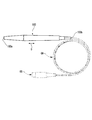
図1は、実施形態に係る超音波探触子100の全体構成の一例を示す側面図である。図1に示すように、超音波探触子100は、細長い棒状に形成されている。
FIG. 1 is a side view showing an example of the entire configuration of an
超音波探触子100は、超音波診断装置の超音波の送受信部として用いられる。この超音波診断装置において、超音波探触子100は、ケーブルCA及び接続端子COを介して超音波診断装置本体(不図示)と電気的に接続される。超音波探触子100の基端部分(図1において超音波探触子100の右側端部分)100bは、ケーブルCAに接続される。超音波探触子100の動作用の電源は、超音波診断装置本体よりケーブルCAを介して超音波探触子100に供給される。超音波探触子100は、被検体へ超音波を送信するとともに、被検体で反射した超音波を受信してこれを電気信号に変換し、これをケーブルCAを介して超音波診断装置本体へ送信する。
The
図2は、超音波探触子100の正面図であり、超音波探触子100を先端100a側(前方)から見た際の図である。図2に示すように、超音波探触子100の先端100a側から見た際の外形は、略真円形状となっている。
FIG. 2 is a front view of the
このような超音波探触子100を含む超音波診断装置は、主として、眼球の眼軸長を測定するために使用される。この場合、被検体は眼球である。ただし、この超音波診断装置は、眼軸長測定以外の用途で用いられるものであってもよい。実施形態に係る超音波探触子100は、例えば眼軸長測定用の超音波探触子であり、超音波探触子100の先端100aの当接面10を眼球に直接当てて使用される。当接面10は、被検体である眼球に対して当接可能に形成され、眼軸長測定の際に眼球に当接される。上記超音波診断装置を用いて眼球の眼軸長を測定する際、超音波探触子100は、眼球に向けて超音波を送信するとともに、眼球で反射した超音波を受信する。また、眼軸長測定の際、超音波探触子100は、眼球に向けて光を射出する。当接面10は、超音波を送受信する超音波送受信面10a、及び、光を射出する光射出面10bを含んでいる。
An ultrasonic diagnostic apparatus including such an
図3は、超音波探触子100の要部断面図であり、図2のA−A線(超音波探触子100の当接面10の中心部分を通りかつ軸方向Dに延びる線)に沿った断面図の要部を示している。図3に示すように、超音波探触子100は、圧電素子20と、音響整合層30と、音響レンズ40と、バッキング材50と、光源60と、光ファイバー70と、探触子ケース80とを含んで構成されている。
FIG. 3 is a cross-sectional view of the main part of the
図4は、図3の部分拡大図であり、図3の超音波探触子100の先端100a部分を拡大した図である。図3及び図4に示すように、圧電素子20は、探触子ケース80に収容されている。圧電素子20は、バッキング材50の前面(先端側の面)52に例えば接着剤を介して固着されている。圧電素子20の後面(基端側の面)22は、バッキング材50の前面52に接合される接合面である。圧電素子20の前面(先端側の面)23は、バッキング材50の前面52に接合される接合面である。圧電素子20は、いわゆる丸型のものであり、超音波探触子100の軸方向Dを厚さ方向とする真円形の円板状に形成されている。圧電素子20の厚さ方向の両端面(主面)22,23は平面となっている。圧電素子20は、圧電性を備え、圧電材料から形成される。圧電素子20は、PZT(チタン酸ジルコン酸鉛)あるいは、PZTを主成分とする材料から形成されている。PZTは、圧電セラミックであり、圧電効率が比較的高い材料の一つである。
FIG. 4 is a partial enlarged view of FIG. 3 and is an enlarged view of a
圧電素子20の厚さ方向の両端面22、23には、それぞれ不図示の電極が設けられている。この電極に所定の交流電圧が印加されることにより、圧電素子20において超音波が発生する。また、圧電素子20は、被検体である眼球で反射した超音波を受信し、受信した超音波を電気信号に変換する。
Electrodes (not shown) are provided on both end surfaces 22 and 23 in the thickness direction of the
圧電素子20の厚さ方向の両端面22,23の中央部分には、圧電素子20を厚さ方向に貫通する第1穴(穴)21が設けられている。第1穴21は、光ファイバー70が挿通可能に形成されている。第1穴21の断面形状は、例えば、光ファイバー70の断面形状と同一形状であり、第1穴21の断面の面積は、例えば、光ファイバー70の断面の面積よりも若干広く設定されている。
At the central portions of both end surfaces 22 and 23 in the thickness direction of the
音響整合層30は、圧電素子20と被検体である眼球との音響特性を整合させるための層である。音響整合層30は、眼球に対して超音波を効率よく透過させるために用いられている。すなわち、超音波探触子100から眼球に向けて超音波を送信した場合に、眼球の表面での超音波の反射を小さくするために設けられている。
The
音響整合層30は、圧電素子20の前方側(超音波送受信面10a側)に配置されている。音響整合層30の前面(先端側の面)32は、音響レンズ40の後面(基端側の面)42と接合する接合面である。音響整合層30の後面(基端側の面)33は、圧電素子20の前面23と接合する接合面である。音響整合層30は、超音波が伝わる方向(超音波探触子100の軸方向D)を厚さ方向とする真円形の円板状に形成されており、厚さ方向の両端面32,33は平面となっている。音響整合層30は、圧電素子20に対して厚さ方向に積層するように設けられている。
The
音響整合層30は、エポキシ樹脂から形成されている。なお、音響整合層30は、エポキシ樹脂に限定されず、種々の材料から形成可能である。また、音響整合層30は、単層構造であってもよいし、積層構造であってもよい。
The
音響整合層30は、超音波が伝わる方向に所定の厚さTを有している。厚さTは、音響整合層30を伝わる超音波の波長をλとした場合にλ/4に設定されている。ここで、厚さTは、超音波の周波数と圧電素子20の材質から設定され、波長λは、音響整合層30中の音速をv、周波数をfとした場合、v/fである。例えば、v=2200m/s、f=10MHzの場合には、波長λは、220μmであり、厚さTは、その4分の1の55μmである。
The
音響整合層30の厚さ方向の両端面(主面)32,33の中央部分には、音響整合層30を厚さ方向に貫通する第2穴31が設けられている。第2穴31は、第1穴21及び後述する第3穴51と連通している。第2穴31は、第1穴21と同様に光ファイバー70が挿通可能に形成される。第2穴31の断面形状は、例えば、光ファイバー70の断面形状と同一形状であり、第2穴31の断面の面積は、例えば、光ファイバー70の断面の面積よりも若干広く設定されている。なお、音響整合層30において、第2穴31は設けられなくてもよい。第2穴31が設けられない場合、音響整合層30は、透明あるいは半透明に形成され、光ファイバーから射出される光を音響整合層30の厚さ方向に透過させるように形成されてもよい。
A
音響レンズ40は、超音波探触子100の先端100a部分に形成されている。音響レンズ40は、当接面10を有している。当接面10は、上述したように、超音波探触子100を用いて眼軸長を測定する際に眼球に当接される。
The
当接面10は、音響レンズ40の前面(先端側の面)41でもあり、超音波探触子100の先端100aに位置している。当接面10は、上述したように、超音波が送受信される超音波送受信面10aと光が射出される光射出面10bとを含んでいる(図2参照)。
The
当接面10は、凹状の曲面となっている。したがって、当接面10は、凸状面や平面などに形成される場合に比べて、被検体である眼球の曲面状の表面に対してより適合する形状となっている。超音波送受信面10a及び光射出面10bは、同一面上に形成される。本実施形態では当接面10は凹状の曲面であるので、超音波送受信面10a及び光射出面10bは、同一曲面上に形成されている。
The
音響レンズ40は、超音波探触子100から送信する超音波を収束させる。このため、超音波送受信面10aは、所定曲率に設定された凹形状の曲面となっている。当接面10において超音波送受信面10aの領域は、超音波探触子100の軸方向D視における音響整合層30の領域とほぼ同一である(図2参照)。
The
超音波探触子100の軸方向Dから見て、音響レンズ40の前面41(当接面10)の外形は真円形となっている。また、音響レンズ40の後面(前面41とは反対側の主面)42は真円形の平面状となっている。なお、音響レンズ40の前面41及び後面42は、真円形に限定されず、例えば、長円形や、楕円形、多角形などであってもよい。また、当接面10の表面形状は、凹面状に限定されず、平面状や、緩やかな凸面状などであってもよい。
When viewed in the axial direction D of the
音響レンズ40は、音響整合層30の前側(超音波探触子100の先端100a側)に配置されている。音響レンズ40の一部は、音響整合層30に対して厚さ方向に重ねるように配置されている。音響レンズ40の後面42の一部は、音響整合層30の接合面32と接合されている。音響レンズ40は、光ファイバー70の前側(先端側)に配置されている。光ファイバー70は音響レンズ40を貫通しておらず、当接面10は光ファイバー70から離間している。音響レンズ40の後面42は、光ファイバー70の先端71と当接しているが、離間していてもよい。音響レンズ40は、探触子ケース80の先端部分に形成された開口部81に嵌め込まれるように固定されている。当接面10を含む音響レンズ40の先端部分は、探触子ケース80の先端82よりも前方に突出しており、被検体である眼球に当接可能な大きさに形成されている。
The
当接面10における光射出面10bの領域は、超音波探触子100の軸方向D視における光ファイバー70の先端71の領域とほぼ同一である(図2参照)。なお、当接面10において、光射出面10bの領域は、超音波送受信面10aの領域と一部が重なってもよいし、超音波送受信面10aの領域とは異なる領域であってもよい。
The area of the
音響レンズ40は眼球に当接するため、音響レンズ40には、生体の眼球に当接した際に異物反応を引き起こすおそれの少ない(生体適合性を有する)材料が用いられる。また、音響レンズ40は、耐電圧性(絶縁性)のある樹脂から形成される。音響レンズ40は、超音波探触子100の軸方向Dに厚さを有している。音響レンズ40の厚さは、超音波探触子100が所定の耐電圧性を備えるように設定される。超音波探触子100において、特に、探触子ケース80の開口部81の内側の部分の耐電圧性は、上記した音響レンズ40を含む構成により確保されている。すなわち、実施形態では、上記したように音響整合層30はλ/4に設定されて薄く形成されており、かつ、超音波探触子100の前面にはポリパラキシリレンコーティング等の保護膜は形成されてはいないが、音響レンズ40として耐電圧性(絶縁性)のある樹脂のものを適用し、かつ、音響レンズ40の厚さを調整することにより、超音波探触子100の耐電圧性が確保されている。
Since the
音響レンズ40を構成する樹脂材料としては、ポリメチルペンテン(polymethylpentene,PMP)が用いられている。ポリメチルペンテンは、比重が比較的小さいプラスチックである。この構成により、音響レンズ40の音響インピーダンスを比較的小さくすることができ、これにより音響レンズ40における超音波の透過効率を高くすることができる。また、ポリメチルペンテンは透明な樹脂であり、音響レンズ40は透明である。この構成により、音響レンズ40において光ファイバー70の先端71から射出される光を光射出面10bまで効率よく透過させることができる。さらに、ポリメチルペンテンは耐薬品性を有し、音響レンズ40は耐薬品性を有する。この構成により、当接面10の洗浄の際などにおいて消毒液等の薬品が用いられる場合であっても、これに起因する音響レンズ40の劣化を抑制することができる。
As a resin material that constitutes the
なお、音響レンズ40は、ポリメチルペンテンのみから形成されてもよいし、ポリメチルペンテンを主成分とする材料から形成されてもよい。また、音響レンズ40は、ポリメチルペンテン以外の材料を主成分とする材料から形成されてもよいし、ポリメチルペンテンを含まず他の樹脂材料を用いて形成されてもよく、例えばシリコンゴムなどであってもよい。また、音響レンズ40は、透明であることに限定されず、半透明であってもよい。音響レンズ40が半透明の場合、音響レンズ40は光ファイバー70の先端71から射出される光が光射出面10bまで届く程度の透光性を有する。
The
バッキング材50は、探触子ケース80に収容された状態で探触子ケース80に固着されている。バッキング材50の前面52には圧電素子20が固着されている。この構成により、バッキング材50は、圧電素子20の余分な振動の発生を抑制する。バッキング材50は、例えば超音波探触子100の軸方向Dを高さ方向とする略円柱形状を含む形状であり、例えばゴム系の樹脂である。パッキング材50の側周面53には、接着剤を配置するための溝54,54が形成されている。探触子ケース80の内部にバッキング材50を固着させる際、バッキング材50を探触子ケース80の内部へ挿入する前に、溝54,54には接着剤が塗布される。溝54の断面形状はV字状となっている。
The
バッキング材50は、超音波探触子100の軸方向D視(高さ方向視)における中央部分に、バッキング材50を軸方向Dに貫通する第3穴51が設けられている。第3穴51は、第1穴21及び第2穴31と連通している。第3穴51は、第1穴21及び第2穴31と同様に光ファイバー70が挿通可能に形成される。第3穴51の断面形状は、例えば、光ファイバー70の断面形状と同一形状であり、第3穴51の断面の面積は、例えば、光ファイバー70の断面の面積よりも若干広く設定されている。第1穴21、第2穴31、及び第3穴51のそれぞれは、超音波探触子100の軸方向Dに見て、同一形状かつ同一の大きさとなっており互いに重なるように形成されている。
The
光源60は、探触子ケース80に収容されており、例えば、光ファイバー70の基端側に配置されている。光源60は、超音波探触子100の光射出面10bを介して射出される光を発生させる。光源60は、例えば、発光ダイオード(LED、Light Emitting Diode)ランプである。光源60の基端部(後方部)は、不図示の電源と電気的に接続されている。この電源から光源60に電力が供給されることにより、光源60が発光する。光源60は、その先端方向(前方)の光ファイバー70に向けて光を射出する。
The
光ファイバー70は、例えば、探触子ケース80に収容されており、光源60の先端側(前方側)に配置されている。光ファイバー70は、光源60に対し離間して配置されている。光ファイバー70は、光源60から受けた光を導光して先端71より前方へ射出する。光ファイバー70は、直線状に形成されており、超音波探触子100の軸方向に延びるように配置されている。光ファイバー70は、第1穴21、第2穴31、及び第3穴51に挿通されており、圧電素子20、音響整合層30、及びバッキング材50を貫通している。一方、上述したように、光ファイバー70は、音響レンズ40を貫通していない。上述したように、光ファイバー70の先端71は、音響レンズ40の後面42に当接しているが、音響レンズ40から離間していてもよい。
The
なお、光源60及び光ファイバー70は、上記した構成に限定されない。例えば、光源60と光ファイバー70とは、個別的に形成されかつ離間して配置されることに代えて、両者を一体であるいは一体的に設けるようにしてもよい。また、光源60は探触子ケース80の外部に設けられてもよい。この場合、超音波探触子100において、光源60の光を光ファイバー70まで導光するための部材が付設されてもよいし、光ファイバー70の基端部分を伸ばし湾曲させて光源60まで引き延ばすようにしてもよい。また、光ファイバー70は、直線状に形成されることに限定されず、光源60の光を音響レンズ40の光射出面10bの裏面まで導光する構成であればよく、例えば曲線状などに形成されてもよい。
The
探触子ケース80は、圧電素子20と、音響整合層30と、音響レンズ40と、バッキング材50と、光源60と、光ファイバー70とを収容可能に形成されている。探触子ケース80は、例えば、絶縁性を有する樹脂から形成されている。探触子ケース80は、圧電素子20、音響整合層30、音響レンズ40、バッキング材50、光源60、及び光ファイバー70を収容して保持する。探触子ケース80は、例えば、使用者が超音波探触子100を把持した際に変形等が生じない剛性を備えるように形成される。探触子ケース80の基端部(後方部)より、ケーブルCAが引き出されている(図1参照)。
The
上記実施形態に係る超音波探触子100は、その表面において、例えばポリパラキシリレンコーティングなどの保護膜を有していない。ただし、超音波探触子100は上記保護膜を有する構成であってもよく、この場合、保護膜は、例えば音響レンズ40の前面41を含む面に成膜されてもよい。
The
次に、眼軸長測定の際の超音波探触子100の具体的な動作の一例について説明する。
超音波探触子100を用いて眼軸長測定が行われる際、超音波探触子100の当接面10は眼球(被検体)に当接される。
Next, an example of a specific operation of the
When axial length measurement is performed using the
当接面10に眼球が当接した状態で、超音波探触子100から眼球へ向けて超音波が送信される。この超音波は、圧電素子20において発生し、音響整合層30及び音響レンズ40をこの順で透過し、超音波送受信面10a(図2参照)を介して送信される。
With the eyeball in contact with the
また、当接面10に眼球が当接した状態で、超音波探触子100から眼球へ向けて光が照射される。この光は、光源60において発生し、光ファイバー70及び音響レンズ40をこの順で透過し、光射出面10b(図2参照)を介して照射される。
Further, in a state in which the eyeball is in contact with the
眼球で反射した超音波は、超音波送受信面10aを介して超音波探触子100に受信される。この受信波は、音響レンズ40及び音響整合層30をこの順で透過し、圧電素子20に到達する。受信波は、圧電素子20において電気信号に変換されて、ケーブルCA(図1参照)へ送信される。
The ultrasound reflected by the eye is received by the
以上のように、上記した実施形態によれば、超音波探触子100の先端100aには超音波を収束させる音響レンズ40が設けられる。従来のものでは、超音波を収束させるために圧電素子及び音響整合層を所定曲率の凹面を有する形状としていたが、上記実施形態では、音響レンズ40を備える構成としたことにより、圧電素子20及び音響整合層30の形状は凹状面を有する形状とする必要がなくなる。上記実施形態の圧電素子20及び音響整合層30は、平面を有する板状であるので、凹状面を有する形状のものに比べて容易に製造することができる。これにより、超音波探触子100を容易に製造することができる。
As described above, according to the above-described embodiment, the
また、上記した実施形態によれば、音響レンズ40は、超音波探触子100が耐電圧性を備えるように耐電圧性(絶縁性)を有する材料から所定厚さに形成される。従来のものでは、音響整合層30を厚く形成しかつ音響整合層30上にポリパラキシリレンを主原料とした保護膜を形成することで、特に探触子ケース80の開口部81で囲まれた部分の耐電圧性を確保していたが、上記実施形態では、超音波探触子100において音響レンズ40が設けられるので、その分、音響整合層30の厚さTの設定可能な範囲を薄くする方向に拡大できる(厚さTをより薄くできる)とともに、超音波探触子100を保護膜を有さずに構成することも可能となる。これにより、音響整合層30の厚さTを例えばλ/4といった薄い厚さに容易に設定することができる。また、上記した実施形態に係る超音波探触子100では、このような保護膜を有さないため、超音波探触子100の製造工程において保護膜の成膜工程は不要であるため、その分、超音波探触子100を低コストで製造することができる。また、音響整合層30の厚さTはλ/4に設定されるので、厚さTが他の値に設定される場合と比較して、音響整合層30において良好な音響整合をとることができる。
Further, according to the above-described embodiment, the
また、上記実施形態によれば、光ファイバー70の先端71側には透明な音響レンズ40が配置され、超音波送受信面10a及び光射出面10bは同一の曲面上に形成される。この構成により、当接面10より光が射出される超音波探触子の構成において、当接面10を滑らかに形成することが容易となる。すなわち、光ファイバー70の先端71側には音響レンズ40が配置されるので、光ファイバー70の存在によって当接面10に段差等が形成されることが防止され、音響レンズ40において滑らかな当接面10を容易に形成することができる。また、音響レンズ40は透明であるため、光ファイバー70から射出される光は音響レンズ40を効率よく透過する。
Further, according to the above-described embodiment, the transparent
続いて、超音波探触子が受信した反射エコー(受信波)の強さ(レベル)の測定結果について説明する。図5は、超音波探触子の反射エコーの強さを示す図である。図5(a)は比較例であり、図5(b)は実施形態の超音波探触子100の測定結果を示す図である。図5(a)、(b)において、縦軸は、反射エコーの強さ(単位:dBm)であり、1マスは5dBである。横軸は、周波数(単位:MHz)である。図5(a)、(b)では、0MHzから20MHzまでの範囲における反射エコーの強さを示している。なお、図5(a)の比較例は、従来型の超音波探触子を用いて測定されたものである。実施形態の超音波探触子100にはポリパラキシリレンコーティングは施されていないのに対して、上記した従来型の超音波探触子にはポリパラキシリレンコーティングが施されている。
Subsequently, measurement results of the intensity (level) of the reflected echo (received wave) received by the ultrasonic probe will be described. FIG. 5 is a diagram showing the strength of the reflection echo of the ultrasonic probe. Fig.5 (a) is a comparative example, and FIG.5 (b) is a figure which shows the measurement result of the
上記測定では、超音波探触子が受信した反射エコーをスペクトラムアナライザを用いて観測した。そして、図5の測定データを用いて、比帯域幅(FB:Fractional Bandwidth)を算出した。比帯域幅の算出方法及び算出結果は、次のとおりである。 In the above measurement, the reflection echo received by the ultrasonic probe was observed using a spectrum analyzer. Then, using the measurement data of FIG. 5, the fractional bandwidth (FB: Fractional Bandwidth) was calculated. The calculation method and the calculation result of the relative bandwidth are as follows.
先ず、観測された反射エコーのピーク(最大レベル点)より6dB低下した点の周波数をFL、FHとしたときに、中心周波数(FC:Center Frequency)(「Fc」と表記する場合がある。)を、FC=(FL+FH)/2[MHz]の式で定義する。ここで、FL(Lower Frequency)(「Fl」と表記する場合がある。)は、−6dB下限周波数である。また、FH(Higher Frequency)は、Fu(upper Frequency)でもあり、−6dB上限周波数である。
First, when the frequency of a
次いで、比帯域幅(FB)を、FB=(FH−FL)/FC×100[%]の式にて定義し、これを算出した。具体的には、図5(a)の比較例の比帯域幅は、上記式より、(11.40−8.56)/9.98×100=28.5%となる。同様に、図5(b)の比帯域幅は、FB=(Fu−Fl)/Fc×100の式より、(12.25−7.95)/10.10×100=42.5%となる。 Next, the relative bandwidth (FB) was defined by the formula FB = (FH−FL) / FC × 100 [%], and this was calculated. Specifically, the relative bandwidth of the comparative example of FIG. 5A is (11.40−8.56) /9.98×100=28.5% according to the above equation. Similarly, the relative bandwidth in FIG. 5B is (12.25-7.95) /10.10×100=42.5% according to the equation FB = (Fu−F1) / Fc × 100. Become.
上記結果から、図5(b)の超音波探触子100の比帯域幅は、42.5%であり、図5(a)の比較例(従来型の超音波探触子の測定結果)の比帯域幅(28.5%)に比べて広くなっている。また、図5に示すように、超音波探触子100の比帯域幅は、比較例に比べて−6dB下限周波数(FL)が低周波側に広くかつ−6dB上限周波数(Fu,FH)が高周波側に広くなっている。この結果、実施形態の超音波探触子100は、従来型の超音波探触子に比べて比帯域幅が広く、特性が良いことが確認された。
From the above results, the relative bandwidth of the
また、実施形態の超音波探触子100は、従来型の超音波探触子に比べて、受信波形におけるパルス幅(Pulse Width)が短くなる。ここで、パルス幅とは、反射エコー(受信エコー)の波高値に対して、リンギング(信号波形の歪み)が1/10(−20dB)、1/100(−40dB)、1/1000(−60dB)以下になる時間である。これにより、実施形態の超音波探触子100は、従来型の超音波探触子に比べて、距離分解能が良くなり、特性が良くなる。
Further, in the
以上、本発明に係る超音波探触子の実施形態について説明したが、本発明は、上述した説明に限定されるものではなく、本発明の要旨を逸脱しない範囲において種々の変更が可能である。また、上記の実施形態で説明した要件の1つ以上は、省略されることがある。そのような変更または改良、省略した形態も本発明の技術的範囲に含まれる。 As mentioned above, although the embodiment of the ultrasound probe concerning the present invention was described, the present invention is not limited to the explanation mentioned above, and various change is possible in the range which does not deviate from the gist of the present invention . Also, one or more of the requirements described in the above embodiments may be omitted. Such modifications, improvements and omissions are also included in the technical scope of the present invention.
上記した実施形態において、圧電素子20は、丸型PZTから形成されていたが、これに限定されない。例えば、圧電素子20の形状については、厚さ方向の端面が凹面状に形成された湾曲した板状のものや、角柱形状のものなどであってもよいし、圧電素子20を構成する材料としては、チタン酸バリウム(BaTiO3)や、チタン酸鉛(PbTiO3)、圧電薄膜、圧電高分子膜などであってもよい。
In the above-described embodiment, the
また、上記した実施形態において、音響整合層30は、円板状のエポキシ樹脂から形成されていたが、これに限定されない。例えば、音響整合層30の形状については、圧電素子20に対して重なるような平面を有する円板状に形成されず、厚さ方向の端面が凹面状に形成された湾曲した板状のものや、角柱形状のものなどであってもよい。
Moreover, in the above-mentioned embodiment, although the
また、上記した実施形態において、音響整合層30の超音波が伝わる方向の厚さTはλ/4に設定されていたが、これに限定されず、例えば、厚さTはλ/2などに設定されてもよい。
Further, in the above-described embodiment, the thickness T of the
また、上記した実施形態において、第1穴21、第2穴31、及び第3穴51は、それぞれ圧電素子20、音響整合層30、バッキング材50の中央部分に形成されかつ光ファイバー70が挿通されていたが、これに限定されず、例えば、上記第1〜3穴21,31,51は、圧電素子20等の中央部分に代えて周辺部分に形成されてもよいし、光ファイバー70が挿通されずに光が穴を通過するだけの構成であってもよい。
In the embodiment described above, the
また、上記した実施形態は光ファイバー70を備えていたが、光ファイバー70を備えるか否かは任意であり、例えば、光源60の光を、光ファイバー70を介さずに直接光射出面10bまで送る構成であってもよい。
In the embodiment described above, the
T…音響整合層の厚さ
20…圧電素子
21…第1穴(穴)
30…音響整合層
40…音響レンズ
60…光源
70…光ファイバー
71…光ファイバーの先端
100…超音波探触子
T: Thickness of acoustic matching layer 20: Piezoelectric element 21: First hole (hole)
DESCRIPTION OF
Claims (3)
超音波を集束させるための音響レンズと、
被検体からの超音波の反射を小さくするための音響整合層と、を備え、
前記圧電素子の中央に穴があり、その穴には光源の光を導光する光ファイバーが貫通し、光を照射しながら超音波を送受信する超音波探触子において、
前記音響レンズの材料に、耐電圧性のある樹脂、主として、ポリメチルペンテンを使用し、
前記音響整合層には、耐電圧性を確保するためのポリパラキシリレンコーティングをしないことで前記音響整合層の厚さをλ/4とし、
前記光ファイバーの先端が前記音響レンズを貫通しないように構成され、
前記圧電素子と前記音響整合層の形状を平面状としたことを特徴とする超音波探触子。 A piezoelectric element for generating an ultrasonic wave having a round shape;
An acoustic lens for focusing ultrasonic waves;
An acoustic matching layer for reducing reflection of ultrasonic waves from the subject;
In an ultrasonic probe which has a hole at the center of the piezoelectric element, an optical fiber for guiding the light of the light source penetrates through the hole, and transmits and receives ultrasonic waves while irradiating the light,
As the material of the acoustic lens, a voltage resistant resin, mainly polymethylpentene, is used.
In the acoustic matching layer, the thickness of the acoustic matching layer is set to λ / 4 by not performing polyparaxylylene coating to secure voltage resistance.
The tip of the optical fiber is configured not to penetrate the acoustic lens;
An ultrasonic probe, wherein the shapes of the piezoelectric element and the acoustic matching layer are planar.
超音波を集束させるための音響レンズと、
被検体からの超音波の反射を小さくするための音響整合層と、を備え、
前記圧電素子の中央に穴があり、その穴には光源の光を導光する光ファイバーが貫通し、光を照射しながら超音波を送受信する超音波探触子において、
前記光ファイバーは、その先端が前記音響レンズを貫通しないように配置され、
前記光ファイバーの先端の光が被検体に届くように前記音響レンズの色を透明又は半透明にし、かつ、前記音響レンズの形状を凹面状としたことを特徴とする超音波探触子。 A piezoelectric element for generating an ultrasonic wave having a round shape;
An acoustic lens for focusing ultrasonic waves;
An acoustic matching layer for reducing reflection of ultrasonic waves from the subject;
In an ultrasonic probe which has a hole at the center of the piezoelectric element, an optical fiber for guiding the light of the light source penetrates through the hole, and transmits and receives ultrasonic waves while irradiating the light,
The optical fiber is arranged such that its tip does not penetrate the acoustic lens,
An ultrasonic probe, wherein a color of the acoustic lens is transparent or translucent so that light at a tip of the optical fiber reaches a subject, and a shape of the acoustic lens is concave.
超音波を集束させるための音響レンズと、
被検体からの超音波の反射を小さくするための音響整合層と、を備え、
前記圧電素子の中央に穴があり、その穴には光源の光を導光する光ファイバーが貫通し、光を照射しながら超音波を送受信する超音波探触子において、
前記音響レンズの材料として、耐電圧性のある樹脂、主として、ポリメチルペンテンを使用し、
前記音響整合層の耐電圧性を確保するためのポリパラキシリレンコーティングを使用しないことで、前記音響整合層の厚さをλ/4とし、
前記圧電素子と前記音響整合層の形状を平面状とし、
前記光ファイバーは、その先端が前記音響レンズを貫通しないように配置され、
前記光ファイバーの先端の光が被検体に届くように音響レンズを透明又は半透明にし、かつ、前記音響レンズの形状を凹面状としたことを特徴とする超音波探触子。
A piezoelectric element for generating an ultrasonic wave having a round shape;
An acoustic lens for focusing ultrasonic waves;
An acoustic matching layer for reducing reflection of ultrasonic waves from the subject;
In an ultrasonic probe which has a hole at the center of the piezoelectric element, an optical fiber for guiding the light of the light source penetrates through the hole, and transmits and receives ultrasonic waves while irradiating the light,
As a material of the acoustic lens, a voltage resistant resin, mainly polymethylpentene, is used.
By not using a polyparaxylylene coating for ensuring the voltage resistance of the acoustic matching layer, the thickness of the acoustic matching layer is λ / 4,
Making the shapes of the piezoelectric element and the acoustic matching layer planar;
The optical fiber is arranged such that its tip does not penetrate the acoustic lens,
An ultrasonic probe, wherein an acoustic lens is transparent or semitransparent so that light at the tip of the optical fiber reaches a subject, and a shape of the acoustic lens is concave.
Priority Applications (3)
| Application Number | Priority Date | Filing Date | Title |
|---|---|---|---|
| JP2017187485A JP2019058574A (en) | 2017-09-28 | 2017-09-28 | Ultrasonic wave probe |
| US16/125,782 US10743757B2 (en) | 2017-09-28 | 2018-09-10 | Ultrasonic transducer |
| CN201811099359.3A CN109567859A (en) | 2017-09-28 | 2018-09-20 | Ultrasonic probe |
Applications Claiming Priority (1)
| Application Number | Priority Date | Filing Date | Title |
|---|---|---|---|
| JP2017187485A JP2019058574A (en) | 2017-09-28 | 2017-09-28 | Ultrasonic wave probe |
Publications (1)
| Publication Number | Publication Date |
|---|---|
| JP2019058574A true JP2019058574A (en) | 2019-04-18 |
Family
ID=65806328
Family Applications (1)
| Application Number | Title | Priority Date | Filing Date |
|---|---|---|---|
| JP2017187485A Pending JP2019058574A (en) | 2017-09-28 | 2017-09-28 | Ultrasonic wave probe |
Country Status (3)
| Country | Link |
|---|---|
| US (1) | US10743757B2 (en) |
| JP (1) | JP2019058574A (en) |
| CN (1) | CN109567859A (en) |
Families Citing this family (5)
| Publication number | Priority date | Publication date | Assignee | Title |
|---|---|---|---|---|
| WO2019083526A1 (en) * | 2017-10-25 | 2019-05-02 | Xinova, LLC | Distributed acoustic detector system |
| CN112716529B (en) * | 2019-10-28 | 2024-07-12 | 深圳市理邦精密仪器股份有限公司 | Eyeball detection equipment and ultrasonic probe thereof |
| US11561202B2 (en) * | 2020-05-13 | 2023-01-24 | Purdue Research Foundation | Ultrasonic device |
| CN111887888A (en) * | 2020-07-09 | 2020-11-06 | 聚融医疗科技(杭州)有限公司 | Method and system for evaluating impedance of ultrasonic probe matching layer based on lens echo |
| KR102456228B1 (en) * | 2020-09-01 | 2022-10-19 | 포항공과대학교 산학협력단 | Ultrasonic-optical multi imaging system based on transpatent ultrasonic sensor |
Family Cites Families (6)
| Publication number | Priority date | Publication date | Assignee | Title |
|---|---|---|---|---|
| JP4248639B2 (en) | 1998-11-17 | 2009-04-02 | オリンパス株式会社 | Ultrasonic probe |
| JP4046152B2 (en) | 1998-11-30 | 2008-02-13 | 日本電波工業株式会社 | Ophthalmic ultrasound probe |
| JP4551111B2 (en) | 2004-04-16 | 2010-09-22 | 日本電波工業株式会社 | Ultrasonic probe |
| JP2009247416A (en) | 2008-04-02 | 2009-10-29 | Nippon Dempa Kogyo Co Ltd | Acoustic lens for ultrasonic probe and ultrasonic probe using the same |
| US20100228132A1 (en) * | 2009-03-08 | 2010-09-09 | Jeffrey Brennan | Systems for controlling optical probe functions during medical and veterinary procedures |
| JP6277899B2 (en) | 2014-07-24 | 2018-02-14 | コニカミノルタ株式会社 | Ultrasonic transducer, ultrasonic probe, and ultrasonic imaging device |
-
2017
- 2017-09-28 JP JP2017187485A patent/JP2019058574A/en active Pending
-
2018
- 2018-09-10 US US16/125,782 patent/US10743757B2/en active Active
- 2018-09-20 CN CN201811099359.3A patent/CN109567859A/en active Pending
Also Published As
| Publication number | Publication date |
|---|---|
| US20190090734A1 (en) | 2019-03-28 |
| US10743757B2 (en) | 2020-08-18 |
| CN109567859A (en) | 2019-04-05 |
Similar Documents
| Publication | Publication Date | Title |
|---|---|---|
| US10743757B2 (en) | Ultrasonic transducer | |
| US10413187B2 (en) | Optical scanning device, imaging device, and TOF type analyzer | |
| JP5584154B2 (en) | Photoacoustic imaging apparatus, photoacoustic imaging method, and probe for photoacoustic imaging apparatus | |
| US9702854B2 (en) | Photoacousticbracket, photoacoustic probe and photoacoustic imaging apparatus having the same | |
| JP5315486B1 (en) | Ultrasonic transducer array, method for manufacturing ultrasonic transducer array, and ultrasonic endoscope | |
| US20150057547A1 (en) | Capacitive transducer and method for manufacturing the same | |
| US20230243967A1 (en) | Transparent ultrasound transducer with light beam shaping and the method for assembling the same | |
| KR20220141507A (en) | Optical-ultrasonic integrated endoscopic probe, endoscopic apparatus and catheter apparatus based on transpatent ultrasonic sensor | |
| JP2019062496A (en) | Ultrasonic probe | |
| JPWO2018025679A1 (en) | Method of manufacturing ultrasonic transducer module and ultrasonic endoscope | |
| US12114962B2 (en) | Placement device for medical or veterinary use, placement tracking system, and method for tracking | |
| JPWO2013187158A1 (en) | Ultrasound unit and ultrasound endoscope | |
| CN113598710A (en) | Optoacoustic endoscopic device | |
| JP2004105741A (en) | Ultrasonic search unit | |
| JP2001178719A (en) | Ultrasonic vibrator | |
| JP2017080132A (en) | Ultrasonic device, ultrasonic probe, electronic apparatus and ultrasonic imaging device | |
| JP6944885B2 (en) | Ultrasonic transducer and ultrasonic endoscope | |
| WO2019082891A1 (en) | Ultrasonic oscillator and ultrasonic endoscope | |
| US9968263B2 (en) | Probe, subject information acquisition apparatus, and method for manufacturing the probe | |
| JP2006288580A (en) | Puncturing probe | |
| JP2010063535A (en) | Ultrasonic probe | |
| WO2016027486A1 (en) | Ultrasound endoscope and ultrasound observation device | |
| JP6619963B2 (en) | Photoacoustic imaging device | |
| TW202403283A (en) | Photoacoustic imaging device and light-transmissible ultrasonic transducer thereof | |
| CN117462076A (en) | Photoacoustic imaging device and light-transmitting ultrasonic transducer thereof |
Legal Events
| Date | Code | Title | Description |
|---|---|---|---|
| A621 | Written request for application examination |
Free format text: JAPANESE INTERMEDIATE CODE: A621 Effective date: 20200528 |
|
| A977 | Report on retrieval |
Free format text: JAPANESE INTERMEDIATE CODE: A971007 Effective date: 20210317 |
|
| A131 | Notification of reasons for refusal |
Free format text: JAPANESE INTERMEDIATE CODE: A131 Effective date: 20210406 |
|
| A02 | Decision of refusal |
Free format text: JAPANESE INTERMEDIATE CODE: A02 Effective date: 20211012 |