EP3088038B1 - Balloon with radiopaque adhesive - Google Patents
Balloon with radiopaque adhesive Download PDFInfo
- Publication number
- EP3088038B1 EP3088038B1 EP16175677.0A EP16175677A EP3088038B1 EP 3088038 B1 EP3088038 B1 EP 3088038B1 EP 16175677 A EP16175677 A EP 16175677A EP 3088038 B1 EP3088038 B1 EP 3088038B1
- Authority
- EP
- European Patent Office
- Prior art keywords
- balloon
- adhesive
- radiopaque
- image
- wall
- Prior art date
- Legal status (The legal status is an assumption and is not a legal conclusion. Google has not performed a legal analysis and makes no representation as to the accuracy of the status listed.)
- Active
Links
- 239000000853 adhesive Substances 0.000 title claims description 151
- 230000001070 adhesive effect Effects 0.000 title claims description 151
- 239000000835 fiber Substances 0.000 claims description 74
- 239000000463 material Substances 0.000 claims description 73
- 239000012530 fluid Substances 0.000 claims description 42
- WFKWXMTUELFFGS-UHFFFAOYSA-N tungsten Chemical compound [W] WFKWXMTUELFFGS-UHFFFAOYSA-N 0.000 claims description 11
- 230000008859 change Effects 0.000 claims description 10
- 229910052721 tungsten Inorganic materials 0.000 claims description 9
- 239000010937 tungsten Substances 0.000 claims description 9
- WMWLMWRWZQELOS-UHFFFAOYSA-N bismuth(III) oxide Inorganic materials O=[Bi]O[Bi]=O WMWLMWRWZQELOS-UHFFFAOYSA-N 0.000 claims description 8
- 229910000420 cerium oxide Inorganic materials 0.000 claims description 8
- BMMGVYCKOGBVEV-UHFFFAOYSA-N oxo(oxoceriooxy)cerium Chemical compound [Ce]=O.O=[Ce]=O BMMGVYCKOGBVEV-UHFFFAOYSA-N 0.000 claims description 8
- BASFCYQUMIYNBI-UHFFFAOYSA-N platinum Chemical compound [Pt] BASFCYQUMIYNBI-UHFFFAOYSA-N 0.000 claims description 6
- 150000001875 compounds Chemical class 0.000 claims description 5
- 229910052761 rare earth metal Inorganic materials 0.000 claims description 5
- 229910052715 tantalum Inorganic materials 0.000 claims description 5
- GUVRBAGPIYLISA-UHFFFAOYSA-N tantalum atom Chemical compound [Ta] GUVRBAGPIYLISA-UHFFFAOYSA-N 0.000 claims description 5
- ATJFFYVFTNAWJD-UHFFFAOYSA-N Tin Chemical compound [Sn] ATJFFYVFTNAWJD-UHFFFAOYSA-N 0.000 claims description 4
- TZCXTZWJZNENPQ-UHFFFAOYSA-L barium sulfate Chemical compound [Ba+2].[O-]S([O-])(=O)=O TZCXTZWJZNENPQ-UHFFFAOYSA-L 0.000 claims description 4
- 150000002910 rare earth metals Chemical class 0.000 claims description 4
- 229910052709 silver Inorganic materials 0.000 claims description 4
- 239000004332 silver Substances 0.000 claims description 4
- 229910052718 tin Inorganic materials 0.000 claims description 4
- BQCADISMDOOEFD-UHFFFAOYSA-N Silver Chemical compound [Ag] BQCADISMDOOEFD-UHFFFAOYSA-N 0.000 claims description 3
- PCHJSUWPFVWCPO-UHFFFAOYSA-N gold Chemical compound [Au] PCHJSUWPFVWCPO-UHFFFAOYSA-N 0.000 claims description 3
- 229910052737 gold Inorganic materials 0.000 claims description 3
- 239000010931 gold Substances 0.000 claims description 3
- 229910052741 iridium Inorganic materials 0.000 claims description 3
- GKOZUEZYRPOHIO-UHFFFAOYSA-N iridium atom Chemical compound [Ir] GKOZUEZYRPOHIO-UHFFFAOYSA-N 0.000 claims description 3
- 229910052697 platinum Inorganic materials 0.000 claims description 3
- 239000011135 tin Substances 0.000 claims description 3
- 229910000014 Bismuth subcarbonate Inorganic materials 0.000 claims description 2
- 229940073609 bismuth oxychloride Drugs 0.000 claims description 2
- MGLUJXPJRXTKJM-UHFFFAOYSA-L bismuth subcarbonate Chemical compound O=[Bi]OC(=O)O[Bi]=O MGLUJXPJRXTKJM-UHFFFAOYSA-L 0.000 claims description 2
- 229940036358 bismuth subcarbonate Drugs 0.000 claims description 2
- BWOROQSFKKODDR-UHFFFAOYSA-N oxobismuth;hydrochloride Chemical compound Cl.[Bi]=O BWOROQSFKKODDR-UHFFFAOYSA-N 0.000 claims description 2
- 230000007704 transition Effects 0.000 claims description 2
- 239000010410 layer Substances 0.000 description 63
- 238000003384 imaging method Methods 0.000 description 41
- 239000012790 adhesive layer Substances 0.000 description 26
- ZWEHNKRNPOVVGH-UHFFFAOYSA-N 2-Butanone Chemical compound CCC(C)=O ZWEHNKRNPOVVGH-UHFFFAOYSA-N 0.000 description 24
- 229940039231 contrast media Drugs 0.000 description 22
- 239000002872 contrast media Substances 0.000 description 22
- 229920002635 polyurethane Polymers 0.000 description 20
- 239000004814 polyurethane Substances 0.000 description 20
- -1 iodine, bismuth compounds Chemical class 0.000 description 17
- 239000012939 laminating adhesive Substances 0.000 description 16
- 229920000139 polyethylene terephthalate Polymers 0.000 description 16
- 239000005020 polyethylene terephthalate Substances 0.000 description 16
- 238000000034 method Methods 0.000 description 15
- 239000000203 mixture Substances 0.000 description 15
- 238000002399 angioplasty Methods 0.000 description 14
- 229920000642 polymer Polymers 0.000 description 14
- FAPWRFPIFSIZLT-UHFFFAOYSA-M Sodium chloride Chemical compound [Na+].[Cl-] FAPWRFPIFSIZLT-UHFFFAOYSA-M 0.000 description 12
- 239000002131 composite material Substances 0.000 description 12
- CSCPPACGZOOCGX-UHFFFAOYSA-N Acetone Chemical compound CC(C)=O CSCPPACGZOOCGX-UHFFFAOYSA-N 0.000 description 10
- 239000011780 sodium chloride Substances 0.000 description 10
- 229920002614 Polyether block amide Polymers 0.000 description 9
- 239000004952 Polyamide Substances 0.000 description 7
- 238000002156 mixing Methods 0.000 description 7
- 239000002245 particle Substances 0.000 description 7
- 229920002647 polyamide Polymers 0.000 description 7
- 230000001681 protective effect Effects 0.000 description 7
- 239000000126 substance Substances 0.000 description 7
- DSUFPYCILZXJFF-UHFFFAOYSA-N 4-[[4-[[4-(pentoxycarbonylamino)cyclohexyl]methyl]cyclohexyl]carbamoyloxy]butyl n-[4-[[4-(butoxycarbonylamino)cyclohexyl]methyl]cyclohexyl]carbamate Chemical compound C1CC(NC(=O)OCCCCC)CCC1CC1CCC(NC(=O)OCCCCOC(=O)NC2CCC(CC3CCC(CC3)NC(=O)OCCCC)CC2)CC1 DSUFPYCILZXJFF-UHFFFAOYSA-N 0.000 description 6
- 239000011521 glass Substances 0.000 description 6
- 239000003550 marker Substances 0.000 description 6
- 229910052751 metal Inorganic materials 0.000 description 6
- 239000002184 metal Substances 0.000 description 6
- 150000002739 metals Chemical class 0.000 description 6
- 230000005855 radiation Effects 0.000 description 6
- 239000007787 solid Substances 0.000 description 6
- 238000005299 abrasion Methods 0.000 description 5
- 238000004519 manufacturing process Methods 0.000 description 5
- 230000008569 process Effects 0.000 description 5
- 239000004433 Thermoplastic polyurethane Substances 0.000 description 4
- 239000002504 physiological saline solution Substances 0.000 description 4
- 229920003023 plastic Polymers 0.000 description 4
- 239000004033 plastic Substances 0.000 description 4
- 229920000728 polyester Polymers 0.000 description 4
- 239000000843 powder Substances 0.000 description 4
- 229920002803 thermoplastic polyurethane Polymers 0.000 description 4
- 229920000785 ultra high molecular weight polyethylene Polymers 0.000 description 4
- 239000004831 Hot glue Substances 0.000 description 3
- 239000004698 Polyethylene Substances 0.000 description 3
- 239000004721 Polyphenylene oxide Substances 0.000 description 3
- 239000004743 Polypropylene Substances 0.000 description 3
- 229920001494 Technora Polymers 0.000 description 3
- 239000004699 Ultra-high molecular weight polyethylene Substances 0.000 description 3
- NIXOWILDQLNWCW-UHFFFAOYSA-N acrylic acid group Chemical group C(C=C)(=O)O NIXOWILDQLNWCW-UHFFFAOYSA-N 0.000 description 3
- 229920001400 block copolymer Polymers 0.000 description 3
- 238000007598 dipping method Methods 0.000 description 3
- 238000009826 distribution Methods 0.000 description 3
- 238000003475 lamination Methods 0.000 description 3
- 239000011224 oxide ceramic Substances 0.000 description 3
- 229910052574 oxide ceramic Inorganic materials 0.000 description 3
- TWNQGVIAIRXVLR-UHFFFAOYSA-N oxo(oxoalumanyloxy)alumane Chemical compound O=[Al]O[Al]=O TWNQGVIAIRXVLR-UHFFFAOYSA-N 0.000 description 3
- 229920000570 polyether Polymers 0.000 description 3
- 229920000573 polyethylene Polymers 0.000 description 3
- 229920001155 polypropylene Polymers 0.000 description 3
- 239000004810 polytetrafluoroethylene Substances 0.000 description 3
- 229920001343 polytetrafluoroethylene Polymers 0.000 description 3
- 239000011253 protective coating Substances 0.000 description 3
- 239000000243 solution Substances 0.000 description 3
- 238000001228 spectrum Methods 0.000 description 3
- 239000004950 technora Substances 0.000 description 3
- GNOGSFBXBWBTIG-UHFFFAOYSA-N Acetrizoic acid Chemical compound CC(=O)NC1=C(I)C=C(I)C(C(O)=O)=C1I GNOGSFBXBWBTIG-UHFFFAOYSA-N 0.000 description 2
- 239000004593 Epoxy Substances 0.000 description 2
- 229910052688 Gadolinium Inorganic materials 0.000 description 2
- 206010019233 Headaches Diseases 0.000 description 2
- AMDBBAQNWSUWGN-UHFFFAOYSA-N Ioversol Chemical compound OCCN(C(=O)CO)C1=C(I)C(C(=O)NCC(O)CO)=C(I)C(C(=O)NCC(O)CO)=C1I AMDBBAQNWSUWGN-UHFFFAOYSA-N 0.000 description 2
- KDLHZDBZIXYQEI-UHFFFAOYSA-N Palladium Chemical compound [Pd] KDLHZDBZIXYQEI-UHFFFAOYSA-N 0.000 description 2
- 239000004642 Polyimide Substances 0.000 description 2
- 239000004820 Pressure-sensitive adhesive Substances 0.000 description 2
- 229920003182 Surlyn® Polymers 0.000 description 2
- 239000005035 Surlyn® Substances 0.000 description 2
- 230000001680 brushing effect Effects 0.000 description 2
- 239000011248 coating agent Substances 0.000 description 2
- 238000000576 coating method Methods 0.000 description 2
- 238000010276 construction Methods 0.000 description 2
- 230000001419 dependent effect Effects 0.000 description 2
- 230000000694 effects Effects 0.000 description 2
- 229920001971 elastomer Polymers 0.000 description 2
- 125000003700 epoxy group Chemical group 0.000 description 2
- UIWYJDYFSGRHKR-UHFFFAOYSA-N gadolinium atom Chemical compound [Gd] UIWYJDYFSGRHKR-UHFFFAOYSA-N 0.000 description 2
- VVDGWALACJEJKG-UHFFFAOYSA-N iodamide Chemical compound CC(=O)NCC1=C(I)C(NC(C)=O)=C(I)C(C(O)=O)=C1I VVDGWALACJEJKG-UHFFFAOYSA-N 0.000 description 2
- 229960004359 iodixanol Drugs 0.000 description 2
- NBQNWMBBSKPBAY-UHFFFAOYSA-N iodixanol Chemical compound IC=1C(C(=O)NCC(O)CO)=C(I)C(C(=O)NCC(O)CO)=C(I)C=1N(C(=O)C)CC(O)CN(C(C)=O)C1=C(I)C(C(=O)NCC(O)CO)=C(I)C(C(=O)NCC(O)CO)=C1I NBQNWMBBSKPBAY-UHFFFAOYSA-N 0.000 description 2
- NTHXOOBQLCIOLC-UHFFFAOYSA-N iohexol Chemical compound OCC(O)CN(C(=O)C)C1=C(I)C(C(=O)NCC(O)CO)=C(I)C(C(=O)NCC(O)CO)=C1I NTHXOOBQLCIOLC-UHFFFAOYSA-N 0.000 description 2
- 229920000554 ionomer Polymers 0.000 description 2
- IUNJANQVIJDFTQ-UHFFFAOYSA-N iopentol Chemical compound COCC(O)CN(C(C)=O)C1=C(I)C(C(=O)NCC(O)CO)=C(I)C(C(=O)NCC(O)CO)=C1I IUNJANQVIJDFTQ-UHFFFAOYSA-N 0.000 description 2
- 238000010030 laminating Methods 0.000 description 2
- 230000004048 modification Effects 0.000 description 2
- 238000012986 modification Methods 0.000 description 2
- 230000002093 peripheral effect Effects 0.000 description 2
- 229920001568 phenolic resin Polymers 0.000 description 2
- 229920002037 poly(vinyl butyral) polymer Polymers 0.000 description 2
- 229920000647 polyepoxide Polymers 0.000 description 2
- 229920001721 polyimide Polymers 0.000 description 2
- 229920001296 polysiloxane Polymers 0.000 description 2
- 229920002689 polyvinyl acetate Polymers 0.000 description 2
- 239000011118 polyvinyl acetate Substances 0.000 description 2
- 239000000047 product Substances 0.000 description 2
- 239000012783 reinforcing fiber Substances 0.000 description 2
- 239000005060 rubber Substances 0.000 description 2
- 239000002356 single layer Substances 0.000 description 2
- 239000002904 solvent Substances 0.000 description 2
- 239000007921 spray Substances 0.000 description 2
- 238000005507 spraying Methods 0.000 description 2
- 229920001169 thermoplastic Polymers 0.000 description 2
- 239000012815 thermoplastic material Substances 0.000 description 2
- 229920001187 thermosetting polymer Polymers 0.000 description 2
- 239000004416 thermosoftening plastic Substances 0.000 description 2
- SBVRILUQXIOGSI-WZTVWXICSA-N 3-acetamido-2,4,6-triiodo-5-[[2-(methylamino)-2-oxoethyl]carbamoyl]benzoic acid;(2r,3r,4r,5s)-6-(methylamino)hexane-1,2,3,4,5-pentol Chemical compound CNC[C@H](O)[C@@H](O)[C@H](O)[C@H](O)CO.CNC(=O)CNC(=O)C1=C(I)C(NC(C)=O)=C(I)C(C(O)=O)=C1I SBVRILUQXIOGSI-WZTVWXICSA-N 0.000 description 1
- ZCYVEMRRCGMTRW-UHFFFAOYSA-N 7553-56-2 Chemical compound [I] ZCYVEMRRCGMTRW-UHFFFAOYSA-N 0.000 description 1
- WKBOTKDWSSQWDR-UHFFFAOYSA-N Bromine atom Chemical compound [Br] WKBOTKDWSSQWDR-UHFFFAOYSA-N 0.000 description 1
- 229910052684 Cerium Inorganic materials 0.000 description 1
- 229910052692 Dysprosium Inorganic materials 0.000 description 1
- 229910052689 Holmium Inorganic materials 0.000 description 1
- UXIGWFXRQKWHHA-UHFFFAOYSA-N Iotalamic acid Chemical compound CNC(=O)C1=C(I)C(NC(C)=O)=C(I)C(C(O)=O)=C1I UXIGWFXRQKWHHA-UHFFFAOYSA-N 0.000 description 1
- VLHUSFYMPUDOEL-WZTVWXICSA-N Iothalamate meglumine Chemical compound CNC[C@H](O)[C@@H](O)[C@H](O)[C@H](O)CO.CNC(=O)C1=C(I)C(NC(C)=O)=C(I)C(C(O)=O)=C1I VLHUSFYMPUDOEL-WZTVWXICSA-N 0.000 description 1
- XUHXFSYUBXNTHU-UHFFFAOYSA-N Iotrolan Chemical compound IC=1C(C(=O)NC(CO)C(O)CO)=C(I)C(C(=O)NC(CO)C(O)CO)=C(I)C=1N(C)C(=O)CC(=O)N(C)C1=C(I)C(C(=O)NC(CO)C(O)CO)=C(I)C(C(=O)NC(CO)C(O)CO)=C1I XUHXFSYUBXNTHU-UHFFFAOYSA-N 0.000 description 1
- PWHULOQIROXLJO-UHFFFAOYSA-N Manganese Chemical compound [Mn] PWHULOQIROXLJO-UHFFFAOYSA-N 0.000 description 1
- BAQCROVBDNBEEB-UBYUBLNFSA-N Metrizamide Chemical compound CC(=O)N(C)C1=C(I)C(NC(C)=O)=C(I)C(C(=O)N[C@@H]2[C@H]([C@H](O)[C@@H](CO)OC2O)O)=C1I BAQCROVBDNBEEB-UBYUBLNFSA-N 0.000 description 1
- 239000000020 Nitrocellulose Substances 0.000 description 1
- 239000004677 Nylon Substances 0.000 description 1
- 229920002396 Polyurea Polymers 0.000 description 1
- 229910000831 Steel Inorganic materials 0.000 description 1
- 229920010741 Ultra High Molecular Weight Polyethylene (UHMWPE) Polymers 0.000 description 1
- FJWGYAHXMCUOOM-QHOUIDNNSA-N [(2s,3r,4s,5r,6r)-2-[(2r,3r,4s,5r,6s)-4,5-dinitrooxy-2-(nitrooxymethyl)-6-[(2r,3r,4s,5r,6s)-4,5,6-trinitrooxy-2-(nitrooxymethyl)oxan-3-yl]oxyoxan-3-yl]oxy-3,5-dinitrooxy-6-(nitrooxymethyl)oxan-4-yl] nitrate Chemical compound O([C@@H]1O[C@@H]([C@H]([C@H](O[N+]([O-])=O)[C@H]1O[N+]([O-])=O)O[C@H]1[C@@H]([C@@H](O[N+]([O-])=O)[C@H](O[N+]([O-])=O)[C@@H](CO[N+]([O-])=O)O1)O[N+]([O-])=O)CO[N+](=O)[O-])[C@@H]1[C@@H](CO[N+]([O-])=O)O[C@@H](O[N+]([O-])=O)[C@H](O[N+]([O-])=O)[C@H]1O[N+]([O-])=O FJWGYAHXMCUOOM-QHOUIDNNSA-N 0.000 description 1
- 229960005216 acetrizoic acid Drugs 0.000 description 1
- 239000000654 additive Substances 0.000 description 1
- 230000000996 additive effect Effects 0.000 description 1
- 230000002411 adverse Effects 0.000 description 1
- 229920000180 alkyd Polymers 0.000 description 1
- 230000004075 alteration Effects 0.000 description 1
- YVPYQUNUQOZFHG-UHFFFAOYSA-N amidotrizoic acid Chemical compound CC(=O)NC1=C(I)C(NC(C)=O)=C(I)C(C(O)=O)=C1I YVPYQUNUQOZFHG-UHFFFAOYSA-N 0.000 description 1
- 229920003180 amino resin Polymers 0.000 description 1
- ZHNUHDYFZUAESO-OUBTZVSYSA-N aminoformaldehyde Chemical compound N[13CH]=O ZHNUHDYFZUAESO-OUBTZVSYSA-N 0.000 description 1
- 229910052788 barium Inorganic materials 0.000 description 1
- DSAJWYNOEDNPEQ-UHFFFAOYSA-N barium atom Chemical compound [Ba] DSAJWYNOEDNPEQ-UHFFFAOYSA-N 0.000 description 1
- 230000004888 barrier function Effects 0.000 description 1
- 230000015572 biosynthetic process Effects 0.000 description 1
- 229910052797 bismuth Inorganic materials 0.000 description 1
- JCXGWMGPZLAOME-UHFFFAOYSA-N bismuth atom Chemical compound [Bi] JCXGWMGPZLAOME-UHFFFAOYSA-N 0.000 description 1
- GDTBXPJZTBHREO-UHFFFAOYSA-N bromine Substances BrBr GDTBXPJZTBHREO-UHFFFAOYSA-N 0.000 description 1
- 229910052794 bromium Inorganic materials 0.000 description 1
- 239000003054 catalyst Substances 0.000 description 1
- 229920006217 cellulose acetate butyrate Polymers 0.000 description 1
- ZMIGMASIKSOYAM-UHFFFAOYSA-N cerium Chemical compound [Ce][Ce][Ce][Ce][Ce][Ce][Ce][Ce][Ce][Ce][Ce][Ce][Ce][Ce][Ce][Ce][Ce][Ce][Ce][Ce][Ce][Ce][Ce][Ce][Ce][Ce][Ce][Ce][Ce][Ce][Ce][Ce][Ce][Ce][Ce][Ce][Ce][Ce] ZMIGMASIKSOYAM-UHFFFAOYSA-N 0.000 description 1
- 239000007795 chemical reaction product Substances 0.000 description 1
- 230000000536 complexating effect Effects 0.000 description 1
- 229920001577 copolymer Polymers 0.000 description 1
- 229920003020 cross-linked polyethylene Polymers 0.000 description 1
- 239000004703 cross-linked polyethylene Substances 0.000 description 1
- 229960005423 diatrizoate Drugs 0.000 description 1
- 230000003292 diminished effect Effects 0.000 description 1
- SLYTULCOCGSBBJ-UHFFFAOYSA-I disodium;2-[[2-[bis(carboxylatomethyl)amino]-3-(4-ethoxyphenyl)propyl]-[2-[bis(carboxylatomethyl)amino]ethyl]amino]acetate;gadolinium(3+) Chemical compound [Na+].[Na+].[Gd+3].CCOC1=CC=C(CC(CN(CCN(CC([O-])=O)CC([O-])=O)CC([O-])=O)N(CC([O-])=O)CC([O-])=O)C=C1 SLYTULCOCGSBBJ-UHFFFAOYSA-I 0.000 description 1
- KBQHZAAAGSGFKK-UHFFFAOYSA-N dysprosium atom Chemical compound [Dy] KBQHZAAAGSGFKK-UHFFFAOYSA-N 0.000 description 1
- 230000007613 environmental effect Effects 0.000 description 1
- 238000000605 extraction Methods 0.000 description 1
- 239000002657 fibrous material Substances 0.000 description 1
- 125000000524 functional group Chemical group 0.000 description 1
- OCDAWJYGVOLXGZ-VPVMAENOSA-K gadobenate dimeglumine Chemical compound [Gd+3].CNC[C@H](O)[C@@H](O)[C@H](O)[C@H](O)CO.CNC[C@H](O)[C@@H](O)[C@H](O)[C@H](O)CO.OC(=O)CN(CC([O-])=O)CCN(CC([O-])=O)CCN(CC(O)=O)C(C([O-])=O)COCC1=CC=CC=C1 OCDAWJYGVOLXGZ-VPVMAENOSA-K 0.000 description 1
- HZHFFEYYPYZMNU-UHFFFAOYSA-K gadodiamide Chemical compound [Gd+3].CNC(=O)CN(CC([O-])=O)CCN(CC([O-])=O)CCN(CC([O-])=O)CC(=O)NC HZHFFEYYPYZMNU-UHFFFAOYSA-K 0.000 description 1
- RYHQMKVRYNEBNJ-BMWGJIJESA-K gadoterate meglumine Chemical compound [Gd+3].CNC[C@H](O)[C@@H](O)[C@H](O)[C@H](O)CO.OC(=O)CN1CCN(CC([O-])=O)CCN(CC([O-])=O)CCN(CC([O-])=O)CC1 RYHQMKVRYNEBNJ-BMWGJIJESA-K 0.000 description 1
- 239000001056 green pigment Substances 0.000 description 1
- 229910052735 hafnium Inorganic materials 0.000 description 1
- VBJZVLUMGGDVMO-UHFFFAOYSA-N hafnium atom Chemical compound [Hf] VBJZVLUMGGDVMO-UHFFFAOYSA-N 0.000 description 1
- 230000036541 health Effects 0.000 description 1
- 229910001385 heavy metal Inorganic materials 0.000 description 1
- 125000005842 heteroatom Chemical group 0.000 description 1
- KJZYNXUDTRRSPN-UHFFFAOYSA-N holmium atom Chemical compound [Ho] KJZYNXUDTRRSPN-UHFFFAOYSA-N 0.000 description 1
- 150000002484 inorganic compounds Chemical class 0.000 description 1
- 229910010272 inorganic material Inorganic materials 0.000 description 1
- 230000003993 interaction Effects 0.000 description 1
- 229960004901 iodamide Drugs 0.000 description 1
- 239000011630 iodine Substances 0.000 description 1
- 229910052740 iodine Inorganic materials 0.000 description 1
- 229960001025 iohexol Drugs 0.000 description 1
- 229960000824 iopentol Drugs 0.000 description 1
- 229940029378 iothalamate Drugs 0.000 description 1
- 229960004537 ioversol Drugs 0.000 description 1
- 229910052746 lanthanum Inorganic materials 0.000 description 1
- FZLIPJUXYLNCLC-UHFFFAOYSA-N lanthanum atom Chemical compound [La] FZLIPJUXYLNCLC-UHFFFAOYSA-N 0.000 description 1
- 239000004816 latex Substances 0.000 description 1
- 229920000126 latex Polymers 0.000 description 1
- 229910052748 manganese Inorganic materials 0.000 description 1
- 239000011572 manganese Substances 0.000 description 1
- 230000013011 mating Effects 0.000 description 1
- 239000011159 matrix material Substances 0.000 description 1
- MIKKOBKEXMRYFQ-WZTVWXICSA-N meglumine amidotrizoate Chemical compound C[NH2+]C[C@H](O)[C@@H](O)[C@H](O)[C@H](O)CO.CC(=O)NC1=C(I)C(NC(C)=O)=C(I)C(C([O-])=O)=C1I MIKKOBKEXMRYFQ-WZTVWXICSA-N 0.000 description 1
- 238000002844 melting Methods 0.000 description 1
- 230000008018 melting Effects 0.000 description 1
- 229960000554 metrizamide Drugs 0.000 description 1
- 229920001220 nitrocellulos Polymers 0.000 description 1
- 229920001778 nylon Polymers 0.000 description 1
- 229910052763 palladium Inorganic materials 0.000 description 1
- 239000005011 phenolic resin Substances 0.000 description 1
- IEQIEDJGQAUEQZ-UHFFFAOYSA-N phthalocyanine Chemical compound N1C(N=C2C3=CC=CC=C3C(N=C3C4=CC=CC=C4C(=N4)N3)=N2)=C(C=CC=C2)C2=C1N=C1C2=CC=CC=C2C4=N1 IEQIEDJGQAUEQZ-UHFFFAOYSA-N 0.000 description 1
- 229920001200 poly(ethylene-vinyl acetate) Polymers 0.000 description 1
- 229920000058 polyacrylate Polymers 0.000 description 1
- 229920006306 polyurethane fiber Polymers 0.000 description 1
- 229920003226 polyurethane urea Polymers 0.000 description 1
- 238000002360 preparation method Methods 0.000 description 1
- 239000011241 protective layer Substances 0.000 description 1
- 238000002601 radiography Methods 0.000 description 1
- 230000002787 reinforcement Effects 0.000 description 1
- 229920005989 resin Polymers 0.000 description 1
- 239000011347 resin Substances 0.000 description 1
- 229910052702 rhenium Inorganic materials 0.000 description 1
- WUAPFZMCVAUBPE-UHFFFAOYSA-N rhenium atom Chemical compound [Re] WUAPFZMCVAUBPE-UHFFFAOYSA-N 0.000 description 1
- 229920002379 silicone rubber Polymers 0.000 description 1
- 239000004945 silicone rubber Substances 0.000 description 1
- UCPVOMHRDXMAIZ-UHFFFAOYSA-M sodium acetrizoate Chemical compound [Na+].CC(=O)NC1=C(I)C=C(I)C(C([O-])=O)=C1I UCPVOMHRDXMAIZ-UHFFFAOYSA-M 0.000 description 1
- 239000010959 steel Substances 0.000 description 1
- 230000001225 therapeutic effect Effects 0.000 description 1
- 238000012800 visualization Methods 0.000 description 1
- 238000004804 winding Methods 0.000 description 1
Images


Classifications
-
- A—HUMAN NECESSITIES
- A61—MEDICAL OR VETERINARY SCIENCE; HYGIENE
- A61M—DEVICES FOR INTRODUCING MEDIA INTO, OR ONTO, THE BODY; DEVICES FOR TRANSDUCING BODY MEDIA OR FOR TAKING MEDIA FROM THE BODY; DEVICES FOR PRODUCING OR ENDING SLEEP OR STUPOR
- A61M25/00—Catheters; Hollow probes
- A61M25/10—Balloon catheters
- A61M25/104—Balloon catheters used for angioplasty
-
- A—HUMAN NECESSITIES
- A61—MEDICAL OR VETERINARY SCIENCE; HYGIENE
- A61F—FILTERS IMPLANTABLE INTO BLOOD VESSELS; PROSTHESES; DEVICES PROVIDING PATENCY TO, OR PREVENTING COLLAPSING OF, TUBULAR STRUCTURES OF THE BODY, e.g. STENTS; ORTHOPAEDIC, NURSING OR CONTRACEPTIVE DEVICES; FOMENTATION; TREATMENT OR PROTECTION OF EYES OR EARS; BANDAGES, DRESSINGS OR ABSORBENT PADS; FIRST-AID KITS
- A61F2/00—Filters implantable into blood vessels; Prostheses, i.e. artificial substitutes or replacements for parts of the body; Appliances for connecting them with the body; Devices providing patency to, or preventing collapsing of, tubular structures of the body, e.g. stents
- A61F2/95—Instruments specially adapted for placement or removal of stents or stent-grafts
- A61F2/958—Inflatable balloons for placing stents or stent-grafts
- A61F2002/9583—Means for holding the stent on the balloon, e.g. using protrusions, adhesives or an outer sleeve
-
- A—HUMAN NECESSITIES
- A61—MEDICAL OR VETERINARY SCIENCE; HYGIENE
- A61M—DEVICES FOR INTRODUCING MEDIA INTO, OR ONTO, THE BODY; DEVICES FOR TRANSDUCING BODY MEDIA OR FOR TAKING MEDIA FROM THE BODY; DEVICES FOR PRODUCING OR ENDING SLEEP OR STUPOR
- A61M25/00—Catheters; Hollow probes
- A61M25/10—Balloon catheters
- A61M25/1002—Balloon catheters characterised by balloon shape
- A61M2025/1004—Balloons with folds, e.g. folded or multifolded
-
- A—HUMAN NECESSITIES
- A61—MEDICAL OR VETERINARY SCIENCE; HYGIENE
- A61M—DEVICES FOR INTRODUCING MEDIA INTO, OR ONTO, THE BODY; DEVICES FOR TRANSDUCING BODY MEDIA OR FOR TAKING MEDIA FROM THE BODY; DEVICES FOR PRODUCING OR ENDING SLEEP OR STUPOR
- A61M25/00—Catheters; Hollow probes
- A61M25/10—Balloon catheters
- A61M2025/1043—Balloon catheters with special features or adapted for special applications
- A61M2025/1075—Balloon catheters with special features or adapted for special applications having a balloon composed of several layers, e.g. by coating or embedding
-
- A—HUMAN NECESSITIES
- A61—MEDICAL OR VETERINARY SCIENCE; HYGIENE
- A61M—DEVICES FOR INTRODUCING MEDIA INTO, OR ONTO, THE BODY; DEVICES FOR TRANSDUCING BODY MEDIA OR FOR TAKING MEDIA FROM THE BODY; DEVICES FOR PRODUCING OR ENDING SLEEP OR STUPOR
- A61M25/00—Catheters; Hollow probes
- A61M25/10—Balloon catheters
- A61M2025/1043—Balloon catheters with special features or adapted for special applications
- A61M2025/1079—Balloon catheters with special features or adapted for special applications having radio-opaque markers in the region of the balloon
Definitions
- the subject invention relates to balloons having a radiopaque adhesive and, more particularly, to layered non-compliant medical balloons with a radiopaque adhesive between balloon layers.
- balloons that are imaged with an imaging system are believed to provide a faint image due to the minimal ability of the balloon wall to absorb or reflect imaging radiation. Such balloons are also believed to provide an image that is not significantly distinguishable from surrounding structures and tissues, and to provide an image that does not readily indicate the inflation status of the balloon or the position of the balloon wall without the use of an imaging fluid. Accordingly, the location and inflation status of such balloons are enhanced by inflating the balloon with a fluid containing a material that provides a more pronounced image.
- a shortcoming of such inflation-dependent imaging methods is that the image obtained is of the fluid within the balloon and not of the balloon itself.
- imaging fluids that provide an adequate image also possess a viscosity that undesirably increases the time required to inflate and deflate the balloon when the fluid is delivered to the balloon through a narrow lumen.
- imaging fluids are more expensive and require more preparation time as compared to less viscous and pre-made fluids such as physiological saline.
- the contrast media presents the strongest image at the center portion of the imaged balloon and the weakest image at the edges of the radiographic image. This is because the x-rays traveling through the center of the balloon pass through a greater quantity of contrast media than at the peripheral edges of the balloon image.
- US 2006/0058867 A1 teaches an elastomeric radiopaque adhesive composition which includes a biocompatible elastomeric matrix and a radiopaque material distributed therein in sufficient amounts to produce the radiopaque image.
- WO 03/037421 A2 discloses a polymeric balloon for an intracorporeal catheter having a plurality of spaced apart, remotely imageable layers which facilitate the folding of the balloon.
- US 2006/0085022 A1 teaches a non-compliant medical balloon that may be changed from a deflated state to an inflated state by increasing pressure within the balloon.
- the present invention is directed to the balloon of claim 1.
- the dependent claims relate to preferred embodiments.
- a balloon and catheter are provided that includes a balloon wall with inner and outer layers with a radiopaque adhesive disposed between and affixing the inner and outer layers.
- the radiopaque adhesive includes an adhesive base and a radiopaque material dispersed in the adhesive base.
- the adhesive base itself is composed of an intrinsically radiopaque polymeric material with or without another radiopaque material dispersed in the adhesive base.
- the balloon preferably also includes layers of fibers that reinforce the balloon, and the fibers are preferably disposed between the inner and outer layers of tire balloon wall within or between layers of the radiopaque adhesive.
- the fibers are arranged in a pattern on the balloon, as layers formed over each other as a weave or braid within a fiber layer, or woven or braided together to form a single fiber layer.
- the radiopaque adhesive is disposed within the balloon wall to form a pattern.
- the balloon is preferably a compliant balloon or, more preferably, a semi-compliant balloon.
- Compliant balloons allow for the doubling of the outer diameter of the balloon when inflated from an operating pressure to a rated burst pressure, and are made of latex, for example.
- Semi-compliant balloons provide for an increase in the balloon outer diameter by 10-15%, and are made of Nylon, for example.
- the balloon is most preferably a non-compliant balloon that inflates to a predetermined size and shape with a predetermined surface area, circumference, or length.
- the preferred non-compliant balloon preferably provides for an increase in an inflated outer diameter that is within 5% of a nominal balloon diameter.
- the balloon is also preferably a high-pressure balloon having a rated burst pressure of 2.027 MPa (20 atm) or greater, for example.
- the balloon is a low-pressure balloon having a rated burst pressure of less than 0.608 mPa (6 atm).
- the balloon preferably has a predetermined total radiographic quantity that is the total amount of radiopaque material present in the structure of the entire balloon, which includes the radiopaque material present in the adhesive of the balloon wall and does not include radiopaque material that is temporarily added to the balloon such as for inflation.
- a non-radiopaque inflation fluid the balloon as a whole contains the same amount of radiopaque material regardless of inflation state as the total quantity of the radiopaque material within the balloon wall remains constant.
- the balloon preferably also possesses a radiographic density that is a ratio of the total radiographic quantity relative to the volume of the balloon, and which is subject to change as the balloon increases or decrease volume between the uninflated and inflated states of the balloon as the total quantity of the radiopaque material in the balloon remains constant while the balloon volume changes.
- the balloon also preferably provides a total radiographic image intensity that characterizes the image that the entire balloon presents to an imaging device when viewed, and that becomes less intense as the balloon is inflated and the fixed quantity of radiopaque material in the balloon is dispersed over a greater volume.
- the radiographic image intensity can also characterize the image present at only a portion of the balloon, such as at the center of the balloon image presented by an imaging system viewing the balloon from a side of the balloon.
- a fiber-reinforced balloon with a wall that includes a radiopaque adhesive that does not add to the radial thickness of the wall.
- the fibers of the fiber-reinforced balloon are preferably disposed in layers with one fiber layer over and contacting an adjacent fiber layer.
- the radiopaque adhesive is disposed in spaces between adjacent fibers of the fiber layers to affix one fiber layer to an adjacent fiber layer.
- a method of imaging a balloon wall includes applying a radiopaque adhesive between two layers of a balloon wall.
- a method of treating a region of a human body by imaging a wall of a balloon includes applying a radiopaque adhesive between two layers of a balloon wall.
- a catheter 10 having a distal portion 11 with a balloon 12 mounted on a catheter tube 14.
- the balloon 12 has a central section 16 and conical end sections 18, 20 that reduce in diameter to join the central section 16 to the catheter tube 14.
- the balloon 12 is sealed to catheter tube 14 at balloon ends 15 on the conical end sections 18, 20 to allow the inflation of the balloon 12 via one of more lumens extending within catheter tube 14 and communicating with the interior of the balloon.
- the catheter tube 14 also includes a guidewire lumen 24 that directs the passage of the guidewire 26 through the catheter 10.
- Balloon 12 has a multi-layered balloon wall 28 forming the balloon 12, and preferably is a non-compliant balloon that has a balloon wall 28 that maintains its size and shape in one or more directions when the balloon is inflated.
- the balloon 12 preferably has a pre-determined surface area that remains constant during and after inflation, and also preferably has a pre-determined length and pre-determined circumference that each, or together, remain constant during and after inflation.
- the balloon 12 also preferably unfolds to a pre-determined diameter when inflated.
- Balloon 12 is also preferably non-compliant in that it maintains a pre-determined shape when inflated.
- the balloon wall 28 includes an inner layer 30 and an outer layer 32. Between layers 30, 32 is an adhesive 34 that secures the outer layer 32 to the inner layer 30.
- Fig. 3 illustrates an exemplary arrangement of layers 30, 32 and adhesive 34.
- the adhesive 34 preferably includes an adhesive base 35 and a radiopaque material 36 dispersed within the adhesive base 35.
- the adhesive base 35 is preferably a laminating adhesive such as a: thermoplastic polyurethane, thermoplastic acrylic, rubber-based adhesive, polyamide, polyvinyl acetate, polyethylene-vinyl alcohol copolymer, solvent-borne adhesive, hot-melt adhesive, polyvinyl butyral, cellulosic derivatives such as cellulose-acetate-butyrate, silicone RTV, or other similar flexible adhesives capable of laminating films or bonding plastic materials together. More preferably, the adhesive base 35 is a solvent-borne adhesive of a flexible thermoplastic material, such as a polyurethane, polyamide, or acrylic polymer.
- a laminating adhesive such as a: thermoplastic polyurethane, thermoplastic acrylic, rubber-based adhesive, polyamide, polyvinyl acetate, polyethylene-vinyl alcohol copolymer, solvent-borne adhesive, hot-melt adhesive, polyvinyl butyral, cellulosic derivatives such as cellulose-acetate-butyrate, silicone RTV, or other
- the adhesive base 35 is a thermoplastic polyurethane adhesive that is applied as a solution, and re-activated with a solvent such as a methyl ethyl ketone applied to the dried adhesive base 35.
- a solvent such as a methyl ethyl ketone applied to the dried adhesive base 35.
- the adhesive base 35 itself is composed of an intrinsically radiopaque polymeric material that contains higher atomic weight heteroatoms covalently or ionically bound into the polymer structure, and that imparts radiopacity to the polymer itself
- polymers include polymers that have covalently bonded iodine or bromine in the polymer structure.
- polymers also include polymers with ionically bonded metals such as cerium, gadolinium, or other rare earth metals, or barium, bismuth, or other metals that have good radiopacity.
- Another intrinsically radiopaque polymer includes a polymer that is capable of complexing a radiopaque compound in the molecular structure of the polymer, such as a polymer that contains functional groups that bind with and form complexes with radiopaque compounds such as iodine, bismuth compounds, rare earth salts, or other substances that exhibit good radiopacity.
- a polymer that contains functional groups that bind with and form complexes with radiopaque compounds such as iodine, bismuth compounds, rare earth salts, or other substances that exhibit good radiopacity.
- an adhesive that is composed of an intrinsically radiopaque polymer, such as the polymers described above, to which the radiopaque material 36 is added and dispersed throughout the adhesive base 35.
- the adhesive base 35 is a two-part adhesive in which the two components are applied separately or as a pre-made mixture to the inner or outer layers 30, 32 that interact to form the adhesive base.
- two-part adhesives include crosslinked polyurethanes, thermoset acrylic adhesives, epoxies, crosslinked polyureas, polyurethaneureas, two-part silicone rubber adhesives, and other two-component adhesive materials.
- the adhesive base is the reaction product of a first and second substance, with the first substance being a component of the inner or outer layers 30, 32, and the second substance being applied to the layers 30, 32 to interact with the first substance to form a two-part adhesive, or to activate the first substance to form the adhesive.
- the adhesive base is a substance that is activated by an external factor to cause the adhesive base to alter and form the adhesive by the application of heat, pressure, or radiation.
- externally-activated adhesives include polyamide hot melt adhesives, ethylene vinyl acetate copolymers, thermoplastic polyurethanes, hot-melt adhesives used in lamination, and pressure sensitive adhesives such as acrylic, silicone, and rubber-based pressure sensitive adhesives.
- the radiopaque material 36 is distributed in the adhesive base 35 in a sufficient quantity to permit imaging of the balloon wall 28 by an imaging method.
- the radiopaque material 36 is preferably a material that absorbs or reflects significant quantities of x-ray or other diagnostically-significant radiation to render an image during a imaging procedure.
- the radiopaque material 36 is more preferably a material that absorbs x-rays. Examples of radiopaque materials include dense metals such as tungsten, tantalum, silver, tin, platinum, gold, iridium, and similar metals known to absorb x-rays. Other examples of radiopaque materials include inorganic compounds that absorb x-rays.
- radiopaque materials include barium sulfate, bismuth trioxide, bismuth subcarbonate, bismuth oxychloride, cerium oxide, compounds of tungsten, tantalum, and rare earth metals. Most preferably, the radiopaque material 36 is tungsten. The radiopaque material 36 is preferably evenly distributed in the adhesive 34.
- the radiopaque materials arc distributed in the adhesive to form patterns, or to facilitate a darker or lighter image at different locations in the balloon wall 28 to form a pattern in the resulting image or to compensate for areas of the balloon that provide a darker or lighter image resulting from the changes in the geometry or structure of the balloon or changes in balloon wall thickness, such as at the conical end sections 18, 20 where the diameter of the balloon changes.
- the adhesive 34 is preferably a predetermined mixture of the adhesive base 35 and the radiopaque material 36 distributed within the adhesive base.
- the volume of radiopaque material distributed in the adhesive is preferably used to determine the intensity of the image that results during x-ray imaging.
- the adhesive is composed of 40-98 volume-% adhesive base and 2-60 volume-% radiopaque material. More preferably, the adhesive is composed of 55-80 volume-% adhesive base and 20-45 volume-% radiopaque material. Most preferably, the adhesive is composed of 65 volume-% adhesive base and 35 volume-% radiopaque material.
- the adhesive 34 is preferably placed along the entire length and circumference of balloon wall 28 to bond the entire mating surfaces of the inner and outer layers 30, 32 to cach other.
- the adhesive 34 is disposed at only portions of the wall and another adhesive, without the radiopaque material 36, is disposed along the remainder of the balloon wall 28 to form a pattern in the radiopaque image of the balloon 12.
- the quantity of radiopaque material 36 in the adhesive 34 is varied to form a pattern in the image of the balloon 12 obtained with an imaging system.
- the patterns of these alternative embodiments preferably form an image of lines or bands in the balloon wall 28.
- the quantity of the radiopaque material in the adhesive is modified to provide a consistent image of the inflated or deflated balloon 12 with an imaging system, by controlling the placement of the radiopaque material 36 to compensate for or minimize variations or patterns created in the image of the balloon 12 caused by variations of balloon geometry or by the presence of a device carried on the balloon.
- the balloon wall 28 is preferably formed with successive layers.
- the balloon is preferably formed by providing the inner layer 30, applying the adhesive 34, and providing the outer layer 32.
- the adhesive 34 is preferably applied onto the exterior of the inner layer 30 by spraying, dipping, brushing, or by other suitable means.
- the adhesive 34 is preferably a single layer that is subsequently covered by the outer layer 32 to form the balloon wall 28.
- reinforcing fibers or filaments are added between the inner and outer layers 30, 32 to increase the balloon strength under pressure or to control the compliance and shape of the finished balloon
- the balloon wall is formed with successive layers disposed on a base balloon.
- a base balloon 38 is provided as an initial balloon structure in the manufacture of the balloon.
- the base balloon is preferably composed of any thermoplastic or thermoset material that is capable of being formed into the desired balloon shape.
- base balloon materials include polyamides, polyesters, polyurethanes, polyethylene, polypropylene, polyamide-polyether block copolymers, polyimides, crosslinked polyethylene, ionomers such as Surlyn®, crosslinked polyurethanes, and other similar polymers that possess the desired properties of strength, flexibility, and distensibility for use in a compliant or non-compliant balloon.
- the base balloon 38 is preferably a PET tube that is stretched under heat and pressure into the desired balloon form, such as to form a cylinder having the central section 16, conical end sections 18, 20, and balloon ends 15 as illustrated in Fig. 1 .
- first adhesive layer 40 is applied to the exterior surface of the base balloon 38 as a first adhesive layer 40.
- the first adhesive layer 40 is preferably applied onto the exterior of the base balloon 38 by spraying, dipping, brushing, or by other suitable means.
- the first adhesive layer 40 includes a radiopaque material distributed within the adhesive. In an alternative embodiment, the first adhesive layer 40 does not include a radiopaque material.
- first fibers 42 are applied to the base balloon 38 to form a fiber layer, and affixed to the base balloon 38 by the first adhesive layer 40.
- some of the adhesive of first adhesive layer 40 moves to partly fill the spaces formed between adjacent fibers 42, with only a minimal or negligible amount of adhesive remaining directly between the fibers 42 and the outer surface of base balloon 38.
- the movement of the adhesive to the spaces between adjacent fibers 42 keeps the adhesive from contributing to the wall thickness of the balloon wall while still providing the desired adhesion properties to affix the first fibers 42 to the base balloon 38.
- the first fibers 42 are preferably disposed in the direction of the longitudinal axis of the balloon or catheter.
- the first fibers 42 extend along the exterior surface of the balloon base 38 for different or varying lengths. Most preferably, some of the fibers of first fibers 42 extend along the length of the only the central section 16 of the balloon, and some of the first fibers 42 extend along the entire length of the balloon to cover the central section 16 and the conical end sections 18, 20.
- the use of varying fibers lengths for the first fibers 42 provides for fewer fibers at the conical end sections 18, 20, which prevents the fiber layer formed by the first fibers 42 from bunching up or creasing as the diameter of the balloon reduces along the length of the conical end sections 18, 20.
- any high strength fibers or filaments are preferably used to impart the desired properties to the balloon.
- suitable fibers include ultrahigh molecular weight polyethylene such as Spectra® or Dyneema® fibers, polyamide fibers, polyimide fibers, ultrahigh molecular weight polyurethane fibers such as Technora®, fibers made from polyesters or polypropylene, or finely drawn strands of metals such as stainless or high tensile steel.
- the first fibers 42 are preferably ultra-high molecular weight polyethylene or Technora® fibers having a filament diameter of about 12 microns that has been flattened to a rectangular profile of about 0.0005 of an inch by 0.020 of an inch.
- more adhesive is applied to the exterior of the composite formed by based balloon 38, first adhesive layer 40, and first fibers 42.
- the adhesive 34 with the radiopaque material 36 is applied to the exterior of the first adhesive layer 40 and first fibers 42 to form an intermediate adhesive layer 43.
- the adhesive of the intermediate adhesive layer 43 is preferably applied as a spray, or deposited by dipping into a bath, or by brush or other suitable means. Applying by spray is more preferable.
- the intermediate layer 43 is applied to form a radiopaque pattern by controlling the placement of the adhesive 34 on the composite, or by the use of another adhesive that does not have a radiopaque property and that is disposed over the composite in a desired pattern.
- a second fiber 44 is disposed over the intermediate adhesive layer 43 and affixed to the underlying first fibers 42 by the adhesive 34.
- the second fiber 44 is preferably composed of any of the aforementioned fiber materials and is more preferably a single ultra-high molecular weight polyethylene or Technora® fiber identical to the first fibers 42.
- the second fiber 44 is preferably wound circumferentially around the base balloon 38 to form a circumferential fiber layer helically extending along the longitudinal length of the balloon 12.
- a second adhesive layer 46 preferably identical to the first adhesive layer 40, is applied to the exterior of the composite of base balloon 38, layers 40 and 43, and fibers 42 and 44.
- the fibers are preferably disposed as layers with the layer of the second fiber 44 disposed over the layer of first fibers 42.
- the fibers form a weave or braided structure within a single layer, with the first fibers 42 disposed to form a first weave layer and the second fiber 44 disposed to form a weave with itself or with another fiber to form a second weave layer.
- the first fibers 42 and the second fiber 44 join together a weave or braided structure to form a single weave or braided layer.
- the second adhesive layer 46 also preferably bonds to a protective outer film (not shown) of the balloon 12.
- a protective outer film on the exterior surface of the balloon to provide abrasion resistance to the balloon surface and to protect the underlying fibers.
- this film is an abrasion resistant material.
- abrasion resistant materials include polyesters, polyamide, polyamide-polyether block copolymers, polyurethanes, ionomers such as Surlyn®, polyethylene, polypropylene, and crosslinkable materials such as polyurethanes or polyethylene.
- a polyether block copolymer such as Pebax® is used as the abrasion resistant material.
- the protective outer film is formed by melting and fusing the second adhesive layer 46 when heat is applied during manufacture.
- the protective outer film includes a radiopaque material dispersed within the film to impart additional radiopacity to the balloon.
- a protective coating is applied to the balloon, instead of by bonding the radiopaque adhesive to a film or by forming a protective film from the adhesive itself.
- protective coatings providing abrasion resistance include epoxies, polyurethanes, polyesters, alkyd resins, polyvinylbutyral, cellulose nitrate, polyvinyl acetate, phenolic resins such as phenol-formaldehyde resins, and amino resins such as amino-formaldehyde resins.
- the protective coating preferably includes some radiopaque material dispersed within it to impart additional radiopacity to the balloon.
- the composite In order to consolidate the laminated composite structure (of base balloon, fibers, adhesive layers, and protective outer film or coating) into a fused balloon wall, the composite is exposed to conditions that cause the layers to intimately bond together.
- the composite of balloon 12 is heated in a die using heat and pressure to fuse the composite materials into a consolidated structure.
- the adhesive is a thermoplastic material, such as a thermoplastic polyurethane
- the application of heat will also soften the adhesive and cause it to flow and bond to the composite materials of the balloon.
- the adhesive contains a catalyst or is a two-part material that requires reaction of the two components in order to cure, the application of heat provides the means to accelerate the curing process.
- Each layer of adhesive is preferably applied in a single application. Alternatively, each layer of adhesive is applied as a composite of multiple applications to achieve a desired layer thickness or a desired disposition of radiopaque material.
- the adhesive 34 preferably has a radial thickness of 2-100 microns, more preferably has a radial thickness of 3-50 microns, and most preferably has a radial thickness of 10-40 microns.
- the intermediate layer 43 has a thickness that allows radial contact between the first fibers 42 and second fiber 44 so as to cause the adhesive 34 of the intermediate layer 43 to move into and occupy the spaces between the adjacent first fibers 42 or adjacent windings of the second fiber 44, thereby allowing the intermediate layer 43 to be present in the balloon wall 28 but not add to the radial thickness of the balloon wall 28.
- Figs. 4F and 4G illustrate an alternative embodiment to that shown in Figs. 4D and 4E , respectively, in which the intermediate adhesive layer 43 is present but does not add to the radial thickness of the balloon wall 28.
- some of the adhesive layers which have radiopaque or non-radiopaque properties, are comprised of materials that soften and flow during the lamination process.
- the radiopaque balloon has a base balloon, a layer of radiopaque adhesive on the outside surface of the base balloon, and a final protective layer such as a film or coating over the exterior surface of the radiopaque adhesive.
- the radiopaque adhesive imparts radiopacity to the balloon and bonds the base balloon to the protective outer layer.
- the adhesive 34 is alternatively applied in a pattern.
- the patterns are preferably made with the selective application of adhesive 34 when applying the intermediate adhesive layer 43, for example, with the use of a narrow PTFE tape that is wrapped over the first fibers 42 to mask areas of the balloon composite prior to the application of the intermediate adhesive layer 43.
- the PTFE tape is then removed after the application of the intermediate adhesive layer 43 to expose areas that do not have the adhesive 34.
- a layer of a non-radiopaque adhesive is then applied that does not have the radiopaque material 36 to coat the entire balloon composite, thereby placing an additional non-radiopaque adhesive layer over the first fibers 42 and the intermediate adhesive layer 43 and to fill in areas that were covered by the PTFE tape.
- the manufacturing process illustrated in Figs. 4A-4E and Figs. 4F-4G is accomplished with the use of a mold or mandrel in place of the base balloon 38.
- the mold or mandrel is subsequently removed after the lamination of the balloon 12 to leave a balloon wall that does not have the base balloon 38, leaving the first adhesive layer 40 and first fibers 42 to form the interior surface of the balloon 12.
- the balloon 12 includes a layer of marker material, such as a marker strip, marker filaments, or marker ring, preferably between the first fibers 42 and second fiber 44 at predetermined locations such as at the balloon ends 15 to form radiopaque markers identifying specific locations on the balloon 12.
- the radiopaque markers preferably have a different radiopacity than the radiopacity of the remainder of the balloon wall 28.
- the marker strips, filaments, or rings are preferably made from a material that exhibits the preferred properties of radiopacity, flexibility, malleability, and processability.
- Suitable materials for use as a marker include tantalum, tin, silver, gold, platinum, rhenium, iridium, palladium, hafnium, tungsten, lanthanum, and other metals that absorb x-rays.
- Preferable materials include silver and tin.
- the deflated balloon 12 is preferably folded and wrapped circumferentially about itself to provide a reduced profile to the balloon 12.
- the wrapped balloon 12 preferably assumes a profile having an outer diameter that is similar to or approximately matching the outer diameter of the catheter tube 14.
- Figs. 5A-5B illustrate an exemplary folded balloon.
- a portion of the exterior of the wrapped balloon 12 is formed to hold a medical device 48 in a collapsed state, which is preferably a stent that is compressed or collapsed to a delivery diameter.
- the inflation of the balloon 12 preferably applies an expanding force to the interior of the medical device 48 to cause it to expand to a greater diameter.
- the balloon 12 is preferably deflated and withdrawn from the interior of the medical device 48, thereby disengaging from the medical device 48.
- the deflated balloon 12 is preferably inserted into a vessel 52 and positioned relative to a region of interest 50.
- the balloon 12 is preferably inflated to cause the exterior surface of the balloon to contact and press against the walls of the vessel 52 in the region of interest 50.
- the balloon 12 is preferably inflated with an inflation fluid delivered to the interior of the balloon through a lumen.
- the quantity of radiopaque material 36 in the balloon wall 28 is fixed when the balloon wall is manufactured, which defines the total radiographic quantity for the balloon 12.
- the constant quantity of radiopaque material in the balloon 12 provides a radiographic density that exhibits a relatively intense average radiopaque image (as compared to the radiopaque image of the inflated balloon) when the balloon is wholly or partially folded, deflated, empty, collapsed, and/or minimally filled with an inflation fluid, such as saline, because the radiopaque material 36 within the adhesive 34 of the balloon 12 will be closely packed together in the folded balloon 12.
- the deflated balloon 12 will also have a relatively greater radiopaque density as compared to the inflated balloon.
- the center portion of an image of the balloon 12 will also provide a radiographic image intensity that exhibits a relatively less pronounced radiopaque image when the balloon is fully inflated with inflation fluid because the radiopaque material 36 in the balloon wall 28 will have moved apart to a greater radial distance from the longitudinal axis of the catheter during the inflation process to cause a relative lighter radiopaque image.
- the edges of the balloon in an image of the balloon will maintain a comparatively intense image during and after inflation because the image of wall is obtained at an oblique angle in which the imaging radiation passes through or reflects off the wall in a direction that is nearly parallel to the surface of the wall, which causes the radiation to be affected by additional radiopaque material as compared to when the radiation passes through the wall at a right angle.
- the inflated balloon 12 as a whole will also have a relatively reduced radiographic image intensity as the balloon inflates because of the increase in balloon volume resulting from the inflation of the balloon.
- the balloon 12 as a whole will also provide a varying radiopaque image as the balloon 12 progresses between the radiopaque extremes provided in the deflated and inflated states of the balloon 12, with a more intense radiopaque image provided with the deflated balloon and a less intense radiopaque image provided with the inflated balloon.
- the center of the image of the balloon will exhibit a relatively intense image when deflated and a relatively less intense image when inflated, and the edges of the image of the balloon will exhibit a relatively constant radiopaque image.
- the balloon 12 thus has an radiographic density that changes when the balloon 12 transitions between deflated and inflated states, which directly corresponds to volume of the balloon at any point relative to the fixed quantity of radiopaque material 36 in the balloon wall 28.
- the image of the center of the radiopaque balloon 12 becomes radiographically lighter as the balloon is inflated, whereas conventional balloons that are not radiopaque become radiographically darker at the center of the balloon image because of the presence of a radiopaque inflation fluid.
- the radiographic density of the entire balloon 12 is determined by comparing the fixed quantity of radiopaque material 36 to the entire volume of the balloon 12. As the total quantity of radiopaque material in the balloon wall 28 is constant, changes in balloon volume cause the radiographic density to change. Referring to Fig. 7A , the radiographic density of the folded balloon 12 is relatively high because the fixed volume of radiopaque material 36 is contained in a relatively small volume of the folded balloon 12. Referring to Fig. 7B , the radiographic density of the inflated balloon 12 is relatively low because the fixed volume of radiopaque material 36 is contained in relatively large volume of the inflated balloon 12. The average change in radiographic density between a fully-deflated, folded balloon and a fully-inflated balloon is proportional to the change in the diameters of the balloon in these two conditions.
- the balloon is typically imaged on a fluoroscope from a position perpendicular to the main balloon axis. From this perspective, the distribution of radiopaque material in the balloon wall provides an image that is advantageously not uniform.
- the radiopaque balloon 12 provides an image that appears to be more radiopaque material at and very near the edges of the balloon image, and less in the center region of the balloon. As such, the image intensity of the center region of the balloon is diminished even further when the balloon is inflated.
- Table 1 below shows the change in average radiographic density for various size balloons of a typical construction, as well as the change that occurs in the center region of the balloon.
- Table 1 Change in radiographic image intensity resulting from inflation for various balloon sizes
- Inflated balloon outer diameter (mm) Deflated balloon outer diameter (mm) Decrease in total balloon radiographic image intensity when balloon is inflated from deflated state (%) Decrease in balloon radiographic image intensity in center region of balloon image when balloon is inflated from deflated state (%)
- 2.03 59.4 71.3 6 2.03 66.2 76.1 7 2.03 71.0 79.5 8 2.03 74.6 82.1 9 2.23 75.2 82.5 10 2.23 77.7 84.2 12 2.41 79.9 85.8 14 2.33 83.4 88.2 16 2.64 83.5 88.3 18 2.69 85.1 89.4 20 2.95 85.3 89.6 22 3.3 85.0 89.4 24 3.99 83.4 88.2 26 3.99 84.7 89.1
- the decrease in total radiographic image intensity between the fully-deflated and fully-inflated balloon preferably ranges from 35-95%, and more preferably ranges from 60-90%.
- radiopaque adhesive in the balloon is an important feature of this invention, as compared to a non-radiopaque balloon filled with radiopaque contrast media.
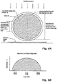
- Figures 8 and 9 illustrate this effect. Since the x-rays used for imaging pass through the balloon in a direction roughly perpendicular to the longitudinal axis of the balloon, the amount of radiopaque adhesive that the x-ray beam encounters is significantly greater at and very near the edges of the balloon, as compared to other areas of the balloon image disposed within the edges of the balloon image. This greater interaction with x-rays at the edges of the balloon image yields an image of a balloon that has defined edges in the image.
- the increase in radiographic density at the balloon image edge, compared to the balloon image center, is a function of the diameter of the inflated balloon and the thickness of the radiopaque adhesive layer.
- Table 2 shows the difference in radiographic image intensity presented by the edges of the imaged balloon as compared to the center of the imaged balloon, for several balloon sizes and radiopaque adhesive thicknesses. Increases in radiographic image intensity at the imaged balloon edge range from 560% to over 2000% as compared to the imaged balloon center.
- Table 2 Radiographic image intensity comparison between balloon image edge and balloon image center Balloon size (mm) Radiopaque adhesive thickness (mm) Thickness of radiopaque adhesive encountered by x-rays directed at the imaged balloon edge from a position orthogonal to the balloon axis (mm) Difference between image intensity at balloon image edge compared to imaged balloon center (%) 5 0.025 0.5006 1001 6 0.025 0.5483 1097 7 0.025 0.5921 1184 8 0.025 0.6329 1266 9 0.025 0.6713 1343 10 0.025 0.7075 1415 12 0.025 0.7750 1550 14 0.025 0.8370 1674 16 0.025 0.8948 1790 18 0.025 0.9490 1898 20 0.025 1.0003 2001 22 0.025 1.0491 2098 24 0.025 1.0957 2191 26 0.025 1.1404 2281 5 0.075 0.8693 580 6 0.075 0.9516 634 7 0.075 1.0274 685 8 0.075 1.0980 732 9 0.075 1.
- the intensity of the imaged balloon edge of a balloon with a radiopaque adhesive is comparable to the intensity of the imaged balloon edge produced by a conventional non-radiopaque balloon that is filled with a radiopaque contrast media.
- Figs. 8A-9B illustrate the distribution of radiographic image intensity that is observed in this comparison.
- Fig. 8A illustrating x-rays directed at the side of a balloon with a radiopaque adhesive
- Fig. 8B representing the image intensity provided by the x-ray imaging
- the balloon image intensity is most intense at the imaged edges of the balloon.
- Fig. 9A illustrating x-rays directed at the side of a conventional balloon filled with a radiopaque contrast media
- Fig. 9A illustrating x-rays directed at the side of a conventional balloon filled with a radiopaque contrast media
- Fig. 9A illustrating x-rays directed at the side of a conventional balloon filled with a radiopaque contrast media
- the balloon image intensity is nonexistent at the edges of the balloon and minimally intense adjacent to the imaged edges of the form presented by the contrast media.
- Conventional balloons using contrast media arc thus believed to provide a fuzzy and poorly defined imaged balloon edge because the x-rays do not image the balloon itself, and because the contrast media imaged near the edges of the form outlined by the contrast media has a minimal or negligible thickness as compared to the thickness presented at the center of the imaged balloon.
- the balloon wall 28 itself (disregarding any inflation fluid or the volume of the balloon) has an constant balloon wall radiographic density that does not change relative to the inflation state of the balloon 12, and that provides an image of the balloon 12 in all inflation states.
- the balloon wall 28 exhibits the same total radiopacity as when the balloon is inflated because the density of the radiopaque material 36 in the balloon wall 28 has not changed.
- the radiopaque image presented of the folded balloon wall 28, as illustrated in Fig. 7A is the additive radiopacities of the folded portions of the balloon wall 28, and the total radiopacity of the folded balloon is thus a function or factor of the radiopacity contribution of each fold of the balloon wall.
- the inflation of the balloon 12 is preferably achieved by supplying the inflation fluid to the interior of the balloon 12 via the catheter tube 14.
- the inflation fluid is preferably a mixture of a physiological saline solution and a radiopaque contrast media, or pure physiological saline solution.
- Available contrast media include iodinated compounds that are either monomeric or dimeric in structure, which includes acetrizoate (Diaginol, Urokon), diatrizoate (Angiographin, Renografin, Urovison), iodamide (Uromiro), ioglicate (Rayvist), iothalamate (Conray), ioxithalamate (Telebrix), iotrolan (Isovist), iodixanol (Visipaque), iohexol (Omnipaque), iopentol (Imagopaque) and ioversol (Optiray).
- the inflation fluid is preferably prepared to have a concentration of radiopaque fluid that is less than 50%.
- the inflation fluid more preferably has a concentration of radiopaque fluid that is from 0% (pure saline solution) to approximately 40%, and yet more preferably in range of approximately 0-20%, and still more preferably in a range of approximately 0-5%, and most preferably at a concentration of 0%.
- radiopaque fluids have a viscosity that is greater than the viscosity of pure physiological saline.
- mixtures of saline with radiopaque fluids have viscosities that are less than undiluted radiopaque fluid but still greater than the viscosity of pure saline.
- the greater viscosities of radiopaque fluids and saline/radiopaque fluid mixtures cause such fluids to move, at a given pressure, more slowly through tubing than the movement observed with pure saline under the same conditions.
- the greater viscosities of radiopaque fluids thus require greater head pressures to push the radiopaque fluids through tubing, and greater head pressures to achieve the balloon inflation times achieved with saline under the same conditions.
- the relatively higher viscosities of radiopaque fluids thus cause the balloon 12 to fill more slowly as compared to a balloon inflated with pure saline. This effect becomes even more pronounced with balloon deflation. This is because, unlike inflation, it is not possible to apply a high pressure on the fluid in the balloon to force it to flow out of the catheter during deflation.
- the maximum pressure available for forcing fluid out is limited to a vacuum that depends in the ambient atmospheric pressure available (0.1013 MPa (14.7 psi or 1 atmosphere)).
- Deflation of the balloon can thus take a considerable time depending on the catheter construction and balloon size. All of these factors are believed to increase the time and/or effort required to complete a medical procedure involving the use of a conventional balloon and radiopaque imaging, and an increase in tire time required to achieve balloon inflation or deflation.
- the exemplary radiopaque balloon provides advantages over existing balloons that do not have a radiopaque balloon wall.
- the exemplary balloon provides faster inflation and deflation times because the balloon produces an image with an imaging system while being inflated with a less viscous fluid as used with convention balloons.
- the exemplary balloon provides a balloon that uses less or no radiopaque fluid, and thus provides a simpler and less expensive method for inflating and imaging a balloon.
- the inflation solution is pure saline solution, the time and expense of mixing solutions is eliminated entirely from the balloon inflation and deflation process.
- the catheter is subsequently moved to initiate extraction of the catheter from the patient, by repositioning the apparently-deflated balloon in an introducer tube, the media remaining in the apparently-deflated balloon can be forced towards the distal end of the balloon to inflated the distal-most end of the balloon that resists complete withdrawal of the balloon into the introducer tube.
- a radiopaque adhesive was prepared by adding the following components into a glass mixing vessel:
- PET Polyethylene terephthalate
- the inflated balloons were sprayed with the radiopaque adhesive to dispose a uniform quantity of adhesive over the surface of the balloons.
- the adhesive was rapidly dried on the surface of the balloon.
- the dried adhesive contained approximately 26 volume % of tungsten and 74 volume % polyurethane.
- the balloons were then wrapped helically with a thin strip of polyether-polyamide copolymer film commercially available as Pebax®.
- the film thickness of approximately 0.0127 mm (0.0005 of an inch), was stretched during wrapping to further reduce the thickness.
- the balloons were placed in laminating dies of a size and shape to allow heat and pressure to be applied to the balloon surface. Balloons were heated to a temperature of approximately 104,444 °C (220 degrees F) with pressure applied to the surface of the balloon to cause the radiopaque laminating adhesive to flow and consolidate the balloon and Pebax® film,
- the result was a radiopaque angioplasty balloon with a double wall thickness of 0.114 mm (0.0045 of an inch).
- the balloons were examined by x-ray imaging and showed excellent visibility without the need to fill them with contrast media.
- a control of conventional PET balloons of tire same size did not exhibit a visible image under the same x-ray imaging.
- a radiopaque laminating adhesive was prepared by adding the following components into a glass mixing container:
- PET angioplasty balloons measuring 12 mm in diameter and with a double wall thickness of approximately 0.051 mm (0.002 of an inch), were mounted and sprayed with the adhesive and dried as described in Example 1.
- the dried adhesive contained approximately 26 volume % of bismuth trioxide, and 74 volume % polyurethane.
- the balloons were then wrapped helically with Pebax® film and laminated under heat and pressure as described in Example 1 to produce consolidated laminated balloons.
- the result was a radiopaque angioplasty balloon with a double wall thickness of 0.117 mm (0.0046 of an inch).
- the balloons were examined by x-ray imaging and showed excellent visibility without the need to fill them with contrast media.
- a radiopaque laminating adhesive was prepared by adding the following components into a plastic mixing container:
- PET angioplasty balloons measuring 12 mm in diameter and with a double wall thickness of approximately 0.051 mm (0.002 of an inch), were mounted and sprayed with a thin coat of the adhesive and dried as described in Example 1.
- the dried adhesive contained approximately 43 volume % of bismuth trioxide and 57 volume % polyurethane.
- the balloons were then wrapped helically with Pebax® film and laminated under heat and pressure as described in Example 1 to produce consolidated laminated balloons.
- the result was a radiopaque angioplasty balloon with a double wall thickness of 0.165 mm (0.0065 of an inch).
- the balloons were examined by x-ray imaging and showed excellent visibility without the need to fill them with contrast media. Because of the higher concentration of bismuth trioxide in the laminating adhesive, and also because of the thicker layer of adhesive, the image for these balloons was more intense than for the balloons prepared in Example 2.
- a radiopaque laminating adhesive was prepared by adding the following components into a glass mixing container:
- PET angioplasty balloons measuring 12 mm in diameter and with a double wall thickness of approximately 0.051 mm (0.002 of an inch), were mounted and sprayed with the adhesive and dried as described in Example 1.
- the dried adhesive contained approximately 42 volume % of tungsten and 58 volume % polyurethane.
- the balloons were then wrapped helically with Pebax® film and laminated under heat and pressure as described in Example 1 to produce consolidated laminated balloons.
- the result was a radiopaque angioplasty balloon with a double wall thickness of 0.152 mm (0.006 of an inch).
- the balloons were examined by x-ray imaging and showed excellent visibility without the need to fill them with contrast media. Because of the higher concentration of tungsten in the laminating adhesive and also because of the thicker layer of adhesive as compared to Example 1, the image for the balloons was more intense than for the balloons prepared in Example 1.
- a radiopaque laminating adhesive was prepared by adding the following components into a plastic mixing container:
- PET angioplasty balloons measuring 12 mm in diameter and with a double wall thickness of approximately 0.051 mm (0.002 of an inch), were mounted and sprayed with the adhesive and dried as described in Example 1.
- the dried adhesive contained approximately 43 volume % of cerium oxide and 57 volume % polyurethane.
- the balloons were then wrapped helically with Pebax® film and laminated under heat and pressure as described in Example 1 to produce consolidated laminated balloons.
- the result was a radiopaque angioplasty balloon with a double wall thickness of approximately 0.157 mm (0.0062 of an inch).
- the balloons were examined by x-ray imaging and showed excellent visibility without the need to fill them with contrast media.
- a radiopaque laminating adhesive was prepared as described in Example 5.
- Polyethylene terephthalate (PET) angioplasty balloons measuring 12 mm in diameter and with a double wall thickness of approximately 0.051 mm (0.002 of an inch), were mounted and sprayed with a small amount of the adhesive and allowed to dry.
- the layer of adhesive was then wrapped circumferentially with a 50 denier yarn composed of ultrahigh molecular weight polyethylene (UHMWPE) commercially available as Spectra ® yarn.
- UHMWPE ultrahigh molecular weight polyethylene
- the yarn was applied at a pitch of approximately 1.97 threads per mm (50 threads per inch) to wrap the balloon.
- the wrapped balloon was then sprayed with additional radiopaque adhesive sufficient to fill in around the fibers and to cover them.
- the balloons were then wrapped helically with Pebax® film and laminated under heat and pressure as described in Example I to produce consolidated laminated fiber-reinforced balloons.
- the result was a fiber-reinforced radiopaque angioplasty balloon with a double wall thickness of approximately 0.163 mm (0.0064 of an inch).
- the balloons were examined by x-ray imaging and showed excellent visibility without the need to fill them with contrast media.
- a radiopaque laminating adhesive was prepared by adding the following components into a plastic mixing container:
- PET angioplasty balloons measuring 12 mm in diameter and with a double wall thickness of approximately 0.051 mm (0.002 of an inch), were mounted and sprayed with a thin layer of the adhesive and dried as described in Example 1.
- the dried adhesive contained approximately 38 volume % of cerium oxide and 62 volume % polyurethane.
- a 50- denier Spectra® yarn was then wrapped circumferentially about the balloon as described in Example 6.
- the green color of the adhesive layer facilitated the visualization of the fibers during the wrapping process. Additional radiopaque adhesive was then applied sufficient to fill in around the fibers and to cover them.
- the balloons were then wrapped helically with Pebax® film and laminated under heat and pressure as described in Example 1 to produce consolidated laminated balloons.
- the result was a radiopaque angioplasty balloon with a double wall thickness of approximately 0.145 mm (0.0057 of an inch).
- the balloons were examined by x-ray imaging and showed excellent visibility without the need to fill them with contrast media.
Landscapes
- Health & Medical Sciences (AREA)
- Heart & Thoracic Surgery (AREA)
- Life Sciences & Earth Sciences (AREA)
- Anesthesiology (AREA)
- Hematology (AREA)
- Biophysics (AREA)
- Pulmonology (AREA)
- Engineering & Computer Science (AREA)
- Veterinary Medicine (AREA)
- Biomedical Technology (AREA)
- Child & Adolescent Psychology (AREA)
- Animal Behavior & Ethology (AREA)
- General Health & Medical Sciences (AREA)
- Public Health (AREA)
- Vascular Medicine (AREA)
- Media Introduction/Drainage Providing Device (AREA)
- Medicines Containing Antibodies Or Antigens For Use As Internal Diagnostic Agents (AREA)
- Apparatus For Radiation Diagnosis (AREA)
Description
- The subject invention relates to balloons having a radiopaque adhesive and, more particularly, to layered non-compliant medical balloons with a radiopaque adhesive between balloon layers.
- Existing balloons that are imaged with an imaging system are believed to provide a faint image due to the minimal ability of the balloon wall to absorb or reflect imaging radiation. Such balloons are also believed to provide an image that is not significantly distinguishable from surrounding structures and tissues, and to provide an image that does not readily indicate the inflation status of the balloon or the position of the balloon wall without the use of an imaging fluid. Accordingly, the location and inflation status of such balloons are enhanced by inflating the balloon with a fluid containing a material that provides a more pronounced image. A shortcoming of such inflation-dependent imaging methods is that the image obtained is of the fluid within the balloon and not of the balloon itself. It is also believed that imaging fluids that provide an adequate image also possess a viscosity that undesirably increases the time required to inflate and deflate the balloon when the fluid is delivered to the balloon through a narrow lumen. Another shortcoming is that such imaging fluids are more expensive and require more preparation time as compared to less viscous and pre-made fluids such as physiological saline.
- In conventional radiography, when a balloon is inflated with an inflation fluid containing an imaging fluid such as contrast media, the contrast media presents the strongest image at the center portion of the imaged balloon and the weakest image at the edges of the radiographic image. This is because the x-rays traveling through the center of the balloon pass through a greater quantity of contrast media than at the peripheral edges of the balloon image. This difference results in an image of the fluid in the balloon that has a strongly-imaged center and undesirably faint edges of the image, that is believed to provide an undefined or unclear image of the peripheral edge of the balloon, thus making it difficult to determine the exact edge of the balloon, reducing the precision of the placement of the inflated balloon, and making it difficult to determine whether the balloon has encountered any constrictions in the vessel being dilated.
- It is thus desirable to provide a balloon that does not require inflation with an imaging fluid, and to provide a balloon that permits direct imaging of the balloon with or without the use of an imaging fluid.
- Further,
US 2006/0058867 A1 teaches an elastomeric radiopaque adhesive composition which includes a biocompatible elastomeric matrix and a radiopaque material distributed therein in sufficient amounts to produce the radiopaque image. - Moreover,
WO 03/037421 A2 -
US 2006/0085022 A1 teaches a non-compliant medical balloon that may be changed from a deflated state to an inflated state by increasing pressure within the balloon. - The present invention is directed to the balloon of claim 1. The dependent claims relate to preferred embodiments.
- A balloon and catheter are provided that includes a balloon wall with inner and outer layers with a radiopaque adhesive disposed between and affixing the inner and outer layers. The radiopaque adhesive includes an adhesive base and a radiopaque material dispersed in the adhesive base. Alternatively, the adhesive base itself is composed of an intrinsically radiopaque polymeric material with or without another radiopaque material dispersed in the adhesive base. The balloon preferably also includes layers of fibers that reinforce the balloon, and the fibers are preferably disposed between the inner and outer layers of tire balloon wall within or between layers of the radiopaque adhesive. In an alternative embodiment, the fibers are arranged in a pattern on the balloon, as layers formed over each other as a weave or braid within a fiber layer, or woven or braided together to form a single fiber layer. In another embodiment, the radiopaque adhesive is disposed within the balloon wall to form a pattern.
- The balloon is preferably a compliant balloon or, more preferably, a semi-compliant balloon. Compliant balloons allow for the doubling of the outer diameter of the balloon when inflated from an operating pressure to a rated burst pressure, and are made of latex, for example. Semi-compliant balloons provide for an increase in the balloon outer diameter by 10-15%, and are made of Nylon, for example. The balloon is most preferably a non-compliant balloon that inflates to a predetermined size and shape with a predetermined surface area, circumference, or length. The preferred non-compliant balloon preferably provides for an increase in an inflated outer diameter that is within 5% of a nominal balloon diameter. The balloon is also preferably a high-pressure balloon having a rated burst pressure of 2.027 MPa (20 atm) or greater, for example. Alternatively, the balloon is a low-pressure balloon having a rated burst pressure of less than 0.608 mPa (6 atm).
- The balloon preferably has a predetermined total radiographic quantity that is the total amount of radiopaque material present in the structure of the entire balloon, which includes the radiopaque material present in the adhesive of the balloon wall and does not include radiopaque material that is temporarily added to the balloon such as for inflation. When using a non-radiopaque inflation fluid, the balloon as a whole contains the same amount of radiopaque material regardless of inflation state as the total quantity of the radiopaque material within the balloon wall remains constant. The balloon preferably also possesses a radiographic density that is a ratio of the total radiographic quantity relative to the volume of the balloon, and which is subject to change as the balloon increases or decrease volume between the uninflated and inflated states of the balloon as the total quantity of the radiopaque material in the balloon remains constant while the balloon volume changes. The balloon also preferably provides a total radiographic image intensity that characterizes the image that the entire balloon presents to an imaging device when viewed, and that becomes less intense as the balloon is inflated and the fixed quantity of radiopaque material in the balloon is dispersed over a greater volume. The radiographic image intensity can also characterize the image present at only a portion of the balloon, such as at the center of the balloon image presented by an imaging system viewing the balloon from a side of the balloon.
- Also provided is a fiber-reinforced balloon with a wall that includes a radiopaque adhesive that does not add to the radial thickness of the wall. The fibers of the fiber-reinforced balloon are preferably disposed in layers with one fiber layer over and contacting an adjacent fiber layer. Preferably, the radiopaque adhesive is disposed in spaces between adjacent fibers of the fiber layers to affix one fiber layer to an adjacent fiber layer.
- Also described is a method of imaging a balloon wall, and a method of imaging a radiopaque adhesive between two layers of a balloon wall. A preferred method of making a balloon wall with a radiopaque adhesive is described that includes applying a radiopaque adhesive between two layers of a balloon wall. Also described is a method of treating a region of a human body by imaging a wall of a balloon, and a method of imaging a radiopaque adhesive disposed between two layers of a balloon wall.
- The accompanying drawings, which are incorporated herein and constitute part of this specification, illustrate exemplary embodiments of the invention, and, together with the general description given above and the detailed description given below, serve to explain the features of the invention.
-
Figure 1 is an isometric view of a portion of an exemplary catheter and of an exemplary balloon. -
Figure 2 is a cross-sectional view of the catheter and balloon ofFig. 1 . -
Figure 3 is a cross-sectional view of a portion of the balloon ofFig. 1 , and an enlarged view of a portion of the balloon ofFig. 2 . -
Figures 4A-4D are cross-sectional views illustrating the manufacture of another embodiment of a balloon.Fig. 4E is a cross-sectional view of the balloon wall ofFig. 4D . -
Figures 4F-4G are the same views presented inFigs. 4D and 4E , respectively, but illustrating another exemplary embodiment. -
Figures 5A-5B are plan and cross-sectional views of a portion of a catheter and a deflated exemplary balloon. -
Figures 6A-6B are plan and cross-sectional views of the catheter and balloon ofFigs. 5A and 5B with an exemplary implantable device. -
Figures 7A-7B are cross-sectional plan views of a deflated and inflated exemplary balloon, illustrating the radiopaque image provided by the balloon wall. -
Figure 8A illustrates x-ray imaging directed at the side of a balloon with a radiopaque adhesive andFigure 8B represents the image intensity provided by the x-ray imaging. -
Figure 9A illustrates x-ray imaging directed at the side of a conventional balloon filled with a radiopaque contrast media andFigure 9B represents the image intensity provided by the x-ray imaging. - The description provided below and in regard to the figures applies to all embodiments unless noted otherwise, and features common to each embodiment are similarly shown and numbered.
- Provided is a
catheter 10 having adistal portion 11 with aballoon 12 mounted on acatheter tube 14. Referring toFigs. 1 and 2 , theballoon 12 has acentral section 16 andconical end sections central section 16 to thecatheter tube 14. Theballoon 12 is sealed tocatheter tube 14 atballoon ends 15 on theconical end sections balloon 12 via one of more lumens extending withincatheter tube 14 and communicating with the interior of the balloon. Thecatheter tube 14 also includes aguidewire lumen 24 that directs the passage of theguidewire 26 through thecatheter 10.Balloon 12 has amulti-layered balloon wall 28 forming theballoon 12, and preferably is a non-compliant balloon that has aballoon wall 28 that maintains its size and shape in one or more directions when the balloon is inflated. Theballoon 12 preferably has a pre-determined surface area that remains constant during and after inflation, and also preferably has a pre-determined length and pre-determined circumference that each, or together, remain constant during and after inflation. Theballoon 12 also preferably unfolds to a pre-determined diameter when inflated.Balloon 12 is also preferably non-compliant in that it maintains a pre-determined shape when inflated. - The
balloon wall 28 includes aninner layer 30 and anouter layer 32. Betweenlayers outer layer 32 to theinner layer 30.Fig. 3 illustrates an exemplary arrangement oflayers adhesive base 35 and aradiopaque material 36 dispersed within theadhesive base 35. Theadhesive base 35 is preferably a laminating adhesive such as a: thermoplastic polyurethane, thermoplastic acrylic, rubber-based adhesive, polyamide, polyvinyl acetate, polyethylene-vinyl alcohol copolymer, solvent-borne adhesive, hot-melt adhesive, polyvinyl butyral, cellulosic derivatives such as cellulose-acetate-butyrate, silicone RTV, or other similar flexible adhesives capable of laminating films or bonding plastic materials together. More preferably, theadhesive base 35 is a solvent-borne adhesive of a flexible thermoplastic material, such as a polyurethane, polyamide, or acrylic polymer. Most preferably, theadhesive base 35 is a thermoplastic polyurethane adhesive that is applied as a solution, and re-activated with a solvent such as a methyl ethyl ketone applied to the driedadhesive base 35. The placement of the adhesive 34 between the inner andouter layers balloon 12, so as to seal and isolate the adhesive 34 from the patient and limit the patient's contact with the adhesive. - In an alternative, the
adhesive base 35 itself is composed of an intrinsically radiopaque polymeric material that contains higher atomic weight heteroatoms covalently or ionically bound into the polymer structure, and that imparts radiopacity to the polymer itself Such polymers include polymers that have covalently bonded iodine or bromine in the polymer structure. Such polymers also include polymers with ionically bonded metals such as cerium, gadolinium, or other rare earth metals, or barium, bismuth, or other metals that have good radiopacity. Another intrinsically radiopaque polymer includes a polymer that is capable of complexing a radiopaque compound in the molecular structure of the polymer, such as a polymer that contains functional groups that bind with and form complexes with radiopaque compounds such as iodine, bismuth compounds, rare earth salts, or other substances that exhibit good radiopacity. Yet another embodiment includes an adhesive that is composed of an intrinsically radiopaque polymer, such as the polymers described above, to which theradiopaque material 36 is added and dispersed throughout theadhesive base 35. - Alternatively, the
adhesive base 35 is a two-part adhesive in which the two components are applied separately or as a pre-made mixture to the inner orouter layers outer layers layers - The
radiopaque material 36 is distributed in theadhesive base 35 in a sufficient quantity to permit imaging of theballoon wall 28 by an imaging method. Theradiopaque material 36 is preferably a material that absorbs or reflects significant quantities of x-ray or other diagnostically-significant radiation to render an image during a imaging procedure. Theradiopaque material 36 is more preferably a material that absorbs x-rays. Examples of radiopaque materials include dense metals such as tungsten, tantalum, silver, tin, platinum, gold, iridium, and similar metals known to absorb x-rays. Other examples of radiopaque materials include inorganic compounds that absorb x-rays. Further examples of radiopaque materials include barium sulfate, bismuth trioxide, bismuth subcarbonate, bismuth oxychloride, cerium oxide, compounds of tungsten, tantalum, and rare earth metals. Most preferably, theradiopaque material 36 is tungsten. Theradiopaque material 36 is preferably evenly distributed in the adhesive 34. Alternatively, the radiopaque materials arc distributed in the adhesive to form patterns, or to facilitate a darker or lighter image at different locations in theballoon wall 28 to form a pattern in the resulting image or to compensate for areas of the balloon that provide a darker or lighter image resulting from the changes in the geometry or structure of the balloon or changes in balloon wall thickness, such as at theconical end sections - The adhesive 34 is preferably a predetermined mixture of the
adhesive base 35 and theradiopaque material 36 distributed within the adhesive base. The volume of radiopaque material distributed in the adhesive is preferably used to determine the intensity of the image that results during x-ray imaging. Preferably, the adhesive is composed of 40-98 volume-% adhesive base and 2-60 volume-% radiopaque material. More preferably, the adhesive is composed of 55-80 volume-% adhesive base and 20-45 volume-% radiopaque material. Most preferably, the adhesive is composed of 65 volume-% adhesive base and 35 volume-% radiopaque material. - The adhesive 34 is preferably placed along the entire length and circumference of
balloon wall 28 to bond the entire mating surfaces of the inner andouter layers radiopaque material 36, is disposed along the remainder of theballoon wall 28 to form a pattern in the radiopaque image of theballoon 12. In another alternative, the quantity ofradiopaque material 36 in the adhesive 34 is varied to form a pattern in the image of theballoon 12 obtained with an imaging system. The patterns of these alternative embodiments preferably form an image of lines or bands in theballoon wall 28. In yet another alternative, the quantity of the radiopaque material in the adhesive is modified to provide a consistent image of the inflated or deflatedballoon 12 with an imaging system, by controlling the placement of theradiopaque material 36 to compensate for or minimize variations or patterns created in the image of theballoon 12 caused by variations of balloon geometry or by the presence of a device carried on the balloon. - The
balloon wall 28 is preferably formed with successive layers. Referring toFig. 3 , the balloon is preferably formed by providing theinner layer 30, applying the adhesive 34, and providing theouter layer 32. The adhesive 34 is preferably applied onto the exterior of theinner layer 30 by spraying, dipping, brushing, or by other suitable means. Referring toFig. 3 , the adhesive 34 is preferably a single layer that is subsequently covered by theouter layer 32 to form theballoon wall 28. In an another embodiment, reinforcing fibers or filaments are added between the inner andouter layers - In a preferred embodiment, the balloon wall is formed with successive layers disposed on a base balloon. Referring to
Fig. 4A , abase balloon 38 is provided as an initial balloon structure in the manufacture of the balloon. The base balloon is preferably composed of any thermoplastic or thermoset material that is capable of being formed into the desired balloon shape. Examples of base balloon materials include polyamides, polyesters, polyurethanes, polyethylene, polypropylene, polyamide-polyether block copolymers, polyimides, crosslinked polyethylene, ionomers such as Surlyn®, crosslinked polyurethanes, and other similar polymers that possess the desired properties of strength, flexibility, and distensibility for use in a compliant or non-compliant balloon. Thebase balloon 38 is preferably a PET tube that is stretched under heat and pressure into the desired balloon form, such as to form a cylinder having thecentral section 16,conical end sections Fig. 1 . - After formation of the
base balloon 38, adhesive is applied to the exterior surface of thebase balloon 38 as a firstadhesive layer 40. The firstadhesive layer 40 is preferably applied onto the exterior of thebase balloon 38 by spraying, dipping, brushing, or by other suitable means. Preferably, although not shown inFig. 4A , the firstadhesive layer 40 includes a radiopaque material distributed within the adhesive. In an alternative embodiment, the firstadhesive layer 40 does not include a radiopaque material. - Referring to
Fig. 4B , a series offirst fibers 42 are applied to thebase balloon 38 to form a fiber layer, and affixed to thebase balloon 38 by the firstadhesive layer 40. Preferably, some of the adhesive of firstadhesive layer 40 moves to partly fill the spaces formed betweenadjacent fibers 42, with only a minimal or negligible amount of adhesive remaining directly between thefibers 42 and the outer surface ofbase balloon 38. The movement of the adhesive to the spaces betweenadjacent fibers 42 keeps the adhesive from contributing to the wall thickness of the balloon wall while still providing the desired adhesion properties to affix thefirst fibers 42 to thebase balloon 38. Thefirst fibers 42 are preferably disposed in the direction of the longitudinal axis of the balloon or catheter. More preferably, thefirst fibers 42 extend along the exterior surface of theballoon base 38 for different or varying lengths. Most preferably, some of the fibers offirst fibers 42 extend along the length of the only thecentral section 16 of the balloon, and some of thefirst fibers 42 extend along the entire length of the balloon to cover thecentral section 16 and theconical end sections first fibers 42 provides for fewer fibers at theconical end sections first fibers 42 from bunching up or creasing as the diameter of the balloon reduces along the length of theconical end sections - Any high strength fibers or filaments are preferably used to impart the desired properties to the balloon. Examples of suitable fibers include ultrahigh molecular weight polyethylene such as Spectra® or Dyneema® fibers, polyamide fibers, polyimide fibers, ultrahigh molecular weight polyurethane fibers such as Technora®, fibers made from polyesters or polypropylene, or finely drawn strands of metals such as stainless or high tensile steel. The
first fibers 42 are preferably ultra-high molecular weight polyethylene or Technora® fibers having a filament diameter of about 12 microns that has been flattened to a rectangular profile of about 0.0005 of an inch by 0.020 of an inch. - Referring to
Fig. 4C , more adhesive is applied to the exterior of the composite formed by basedballoon 38, firstadhesive layer 40, andfirst fibers 42. Preferably, the adhesive 34 with theradiopaque material 36 is applied to the exterior of the firstadhesive layer 40 andfirst fibers 42 to form anintermediate adhesive layer 43. The adhesive of theintermediate adhesive layer 43 is preferably applied as a spray, or deposited by dipping into a bath, or by brush or other suitable means. Applying by spray is more preferable. In an alternative, theintermediate layer 43 is applied to form a radiopaque pattern by controlling the placement of the adhesive 34 on the composite, or by the use of another adhesive that does not have a radiopaque property and that is disposed over the composite in a desired pattern. - Referring to
Fig. 4D , asecond fiber 44 is disposed over theintermediate adhesive layer 43 and affixed to the underlyingfirst fibers 42 by the adhesive 34. Thesecond fiber 44 is preferably composed of any of the aforementioned fiber materials and is more preferably a single ultra-high molecular weight polyethylene or Technora® fiber identical to thefirst fibers 42. Thesecond fiber 44 is preferably wound circumferentially around thebase balloon 38 to form a circumferential fiber layer helically extending along the longitudinal length of theballoon 12. Referring toFigs. 4D-4E , a secondadhesive layer 46, preferably identical to the firstadhesive layer 40, is applied to the exterior of the composite ofbase balloon 38, layers 40 and 43, andfibers second fiber 44 disposed over the layer offirst fibers 42. Alternatively, the fibers form a weave or braided structure within a single layer, with thefirst fibers 42 disposed to form a first weave layer and thesecond fiber 44 disposed to form a weave with itself or with another fiber to form a second weave layer. In another alternative, thefirst fibers 42 and thesecond fiber 44 join together a weave or braided structure to form a single weave or braided layer. - Although not shown in
Figs. 4D-4E , the secondadhesive layer 46 also preferably bonds to a protective outer film (not shown) of theballoon 12. It is preferable to include a protective outer film on the exterior surface of the balloon to provide abrasion resistance to the balloon surface and to protect the underlying fibers. Preferably, this film is an abrasion resistant material. Examples of abrasion resistant materials include polyesters, polyamide, polyamide-polyether block copolymers, polyurethanes, ionomers such as Surlyn®, polyethylene, polypropylene, and crosslinkable materials such as polyurethanes or polyethylene. Preferably, a polyether block copolymer such as Pebax® is used as the abrasion resistant material. In an alternative embodiment, the protective outer film is formed by melting and fusing the secondadhesive layer 46 when heat is applied during manufacture. In another alternative, the protective outer film includes a radiopaque material dispersed within the film to impart additional radiopacity to the balloon. - In another alternative, a protective coating is applied to the balloon, instead of by bonding the radiopaque adhesive to a film or by forming a protective film from the adhesive itself. Examples of protective coatings providing abrasion resistance include epoxies, polyurethanes, polyesters, alkyd resins, polyvinylbutyral, cellulose nitrate, polyvinyl acetate, phenolic resins such as phenol-formaldehyde resins, and amino resins such as amino-formaldehyde resins. The protective coating preferably includes some radiopaque material dispersed within it to impart additional radiopacity to the balloon.
- In order to consolidate the laminated composite structure (of base balloon, fibers, adhesive layers, and protective outer film or coating) into a fused balloon wall, the composite is exposed to conditions that cause the layers to intimately bond together. Preferably, the composite of
balloon 12 is heated in a die using heat and pressure to fuse the composite materials into a consolidated structure. Preferably, if the adhesive is a thermoplastic material, such as a thermoplastic polyurethane, the application of heat will also soften the adhesive and cause it to flow and bond to the composite materials of the balloon. Also preferably, if the adhesive contains a catalyst or is a two-part material that requires reaction of the two components in order to cure, the application of heat provides the means to accelerate the curing process. - Each layer of adhesive is preferably applied in a single application. Alternatively, each layer of adhesive is applied as a composite of multiple applications to achieve a desired layer thickness or a desired disposition of radiopaque material. The adhesive 34 preferably has a radial thickness of 2-100 microns, more preferably has a radial thickness of 3-50 microns, and most preferably has a radial thickness of 10-40 microns. In a preferred embodiment having fiber reinforcement, the
intermediate layer 43 has a thickness that allows radial contact between thefirst fibers 42 andsecond fiber 44 so as to cause the adhesive 34 of theintermediate layer 43 to move into and occupy the spaces between the adjacentfirst fibers 42 or adjacent windings of thesecond fiber 44, thereby allowing theintermediate layer 43 to be present in theballoon wall 28 but not add to the radial thickness of theballoon wall 28.Figs. 4F and 4G illustrate an alternative embodiment to that shown inFigs. 4D and 4E , respectively, in which theintermediate adhesive layer 43 is present but does not add to the radial thickness of theballoon wall 28. In an alternative, some of the adhesive layers, which have radiopaque or non-radiopaque properties, are comprised of materials that soften and flow during the lamination process. - Other embodiments of the radiopaque balloon are similarly constructed but without the reinforcing fibers. In this alternative embodiment, the balloon has a base balloon, a layer of radiopaque adhesive on the outside surface of the base balloon, and a final protective layer such as a film or coating over the exterior surface of the radiopaque adhesive. The radiopaque adhesive imparts radiopacity to the balloon and bonds the base balloon to the protective outer layer.
- The adhesive 34 is alternatively applied in a pattern. The patterns are preferably made with the selective application of adhesive 34 when applying the
intermediate adhesive layer 43, for example, with the use of a narrow PTFE tape that is wrapped over thefirst fibers 42 to mask areas of the balloon composite prior to the application of theintermediate adhesive layer 43. The PTFE tape is then removed after the application of theintermediate adhesive layer 43 to expose areas that do not have the adhesive 34. A layer of a non-radiopaque adhesive is then applied that does not have theradiopaque material 36 to coat the entire balloon composite, thereby placing an additional non-radiopaque adhesive layer over thefirst fibers 42 and theintermediate adhesive layer 43 and to fill in areas that were covered by the PTFE tape. - Alternatively, the manufacturing process illustrated in
Figs. 4A-4E andFigs. 4F-4G is accomplished with the use of a mold or mandrel in place of thebase balloon 38. The mold or mandrel is subsequently removed after the lamination of theballoon 12 to leave a balloon wall that does not have thebase balloon 38, leaving the firstadhesive layer 40 andfirst fibers 42 to form the interior surface of theballoon 12. - In another alternative, the
balloon 12 includes a layer of marker material, such as a marker strip, marker filaments, or marker ring, preferably between thefirst fibers 42 andsecond fiber 44 at predetermined locations such as at the balloon ends 15 to form radiopaque markers identifying specific locations on theballoon 12. The radiopaque markers preferably have a different radiopacity than the radiopacity of the remainder of theballoon wall 28. The marker strips, filaments, or rings are preferably made from a material that exhibits the preferred properties of radiopacity, flexibility, malleability, and processability. Suitable materials for use as a marker include tantalum, tin, silver, gold, platinum, rhenium, iridium, palladium, hafnium, tungsten, lanthanum, and other metals that absorb x-rays. Preferable materials include silver and tin. - The deflated
balloon 12 is preferably folded and wrapped circumferentially about itself to provide a reduced profile to theballoon 12. The wrappedballoon 12 preferably assumes a profile having an outer diameter that is similar to or approximately matching the outer diameter of thecatheter tube 14.Figs. 5A-5B illustrate an exemplary folded balloon. Referring toFigs. 6A-6B , a portion of the exterior of the wrappedballoon 12 is formed to hold amedical device 48 in a collapsed state, which is preferably a stent that is compressed or collapsed to a delivery diameter. The inflation of theballoon 12 preferably applies an expanding force to the interior of themedical device 48 to cause it to expand to a greater diameter. After themedical device 48 has been expanded, and if designed to maintain a stable expanded configuration, theballoon 12 is preferably deflated and withdrawn from the interior of themedical device 48, thereby disengaging from themedical device 48. - Referring to
Fig. 7A , the deflatedballoon 12 is preferably inserted into avessel 52 and positioned relative to a region ofinterest 50. Referring toFig. 7B , once positioned, theballoon 12 is preferably inflated to cause the exterior surface of the balloon to contact and press against the walls of thevessel 52 in the region ofinterest 50. The an alternative embodiment having amedical device 48 mounted on the deflatedballoon 12, the inflation of theballoon 12 expands themedical device 48 to cause the exterior of the medical device to press against the vessel walls to achieve a therapeutic effect. Theballoon 12 is preferably inflated with an inflation fluid delivered to the interior of the balloon through a lumen. - The quantity of
radiopaque material 36 in theballoon wall 28 is fixed when the balloon wall is manufactured, which defines the total radiographic quantity for theballoon 12. Referring toFigs. 7A and 7B , the constant quantity of radiopaque material in theballoon 12 provides a radiographic density that exhibits a relatively intense average radiopaque image (as compared to the radiopaque image of the inflated balloon) when the balloon is wholly or partially folded, deflated, empty, collapsed, and/or minimally filled with an inflation fluid, such as saline, because theradiopaque material 36 within the adhesive 34 of theballoon 12 will be closely packed together in the foldedballoon 12. The deflatedballoon 12 will also have a relatively greater radiopaque density as compared to the inflated balloon. The center portion of an image of theballoon 12 will also provide a radiographic image intensity that exhibits a relatively less pronounced radiopaque image when the balloon is fully inflated with inflation fluid because theradiopaque material 36 in theballoon wall 28 will have moved apart to a greater radial distance from the longitudinal axis of the catheter during the inflation process to cause a relative lighter radiopaque image. Also the edges of the balloon in an image of the balloon will maintain a comparatively intense image during and after inflation because the image of wall is obtained at an oblique angle in which the imaging radiation passes through or reflects off the wall in a direction that is nearly parallel to the surface of the wall, which causes the radiation to be affected by additional radiopaque material as compared to when the radiation passes through the wall at a right angle. Theinflated balloon 12 as a whole will also have a relatively reduced radiographic image intensity as the balloon inflates because of the increase in balloon volume resulting from the inflation of the balloon. Theballoon 12 as a whole will also provide a varying radiopaque image as theballoon 12 progresses between the radiopaque extremes provided in the deflated and inflated states of theballoon 12, with a more intense radiopaque image provided with the deflated balloon and a less intense radiopaque image provided with the inflated balloon. Furthermore, the center of the image of the balloon will exhibit a relatively intense image when deflated and a relatively less intense image when inflated, and the edges of the image of the balloon will exhibit a relatively constant radiopaque image. - The
balloon 12 thus has an radiographic density that changes when theballoon 12 transitions between deflated and inflated states, which directly corresponds to volume of the balloon at any point relative to the fixed quantity ofradiopaque material 36 in theballoon wall 28. Specifically, the image of the center of theradiopaque balloon 12 becomes radiographically lighter as the balloon is inflated, whereas conventional balloons that are not radiopaque become radiographically darker at the center of the balloon image because of the presence of a radiopaque inflation fluid. - The radiographic density of the
entire balloon 12 is determined by comparing the fixed quantity ofradiopaque material 36 to the entire volume of theballoon 12. As the total quantity of radiopaque material in theballoon wall 28 is constant, changes in balloon volume cause the radiographic density to change. Referring toFig. 7A , the radiographic density of the foldedballoon 12 is relatively high because the fixed volume ofradiopaque material 36 is contained in a relatively small volume of the foldedballoon 12. Referring toFig. 7B , the radiographic density of theinflated balloon 12 is relatively low because the fixed volume ofradiopaque material 36 is contained in relatively large volume of theinflated balloon 12. The average change in radiographic density between a fully-deflated, folded balloon and a fully-inflated balloon is proportional to the change in the diameters of the balloon in these two conditions. - It is believed that, during a typical medical procedure, the balloon is typically imaged on a fluoroscope from a position perpendicular to the main balloon axis. From this perspective, the distribution of radiopaque material in the balloon wall provides an image that is advantageously not uniform. The
radiopaque balloon 12 provides an image that appears to be more radiopaque material at and very near the edges of the balloon image, and less in the center region of the balloon. As such, the image intensity of the center region of the balloon is diminished even further when the balloon is inflated. Table 1 below shows the change in average radiographic density for various size balloons of a typical construction, as well as the change that occurs in the center region of the balloon.Table 1 - Change in radiographic image intensity resulting from inflation for various balloon sizes Inflated balloon outer diameter (mm) Deflated balloon outer diameter (mm) Decrease in total balloon radiographic image intensity when balloon is inflated from deflated state (%) Decrease in balloon radiographic image intensity in center region of balloon image when balloon is inflated from deflated state (%) 5 2.03 59.4 71.3 6 2.03 66.2 76.1 7 2.03 71.0 79.5 8 2.03 74.6 82.1 9 2.23 75.2 82.5 10 2.23 77.7 84.2 12 2.41 79.9 85.8 14 2.33 83.4 88.2 16 2.64 83.5 88.3 18 2.69 85.1 89.4 20 2.95 85.3 89.6 22 3.3 85.0 89.4 24 3.99 83.4 88.2 26 3.99 84.7 89.1 - The decrease in total radiographic image intensity between the fully-deflated and fully-inflated balloon preferably ranges from 35-95%, and more preferably ranges from 60-90%.
- The distribution of radiopaque adhesive in the balloon, as viewed under a fluoroscope, is an important feature of this invention, as compared to a non-radiopaque balloon filled with radiopaque contrast media.
Figures 8 and9 illustrate this effect. Since the x-rays used for imaging pass through the balloon in a direction roughly perpendicular to the longitudinal axis of the balloon, the amount of radiopaque adhesive that the x-ray beam encounters is significantly greater at and very near the edges of the balloon, as compared to other areas of the balloon image disposed within the edges of the balloon image. This greater interaction with x-rays at the edges of the balloon image yields an image of a balloon that has defined edges in the image. The increase in radiographic density at the balloon image edge, compared to the balloon image center, is a function of the diameter of the inflated balloon and the thickness of the radiopaque adhesive layer. Table 2 shows the difference in radiographic image intensity presented by the edges of the imaged balloon as compared to the center of the imaged balloon, for several balloon sizes and radiopaque adhesive thicknesses. Increases in radiographic image intensity at the imaged balloon edge range from 560% to over 2000% as compared to the imaged balloon center.Table 2 - Radiographic image intensity comparison between balloon image edge and balloon image center Balloon size (mm) Radiopaque adhesive thickness (mm) Thickness of radiopaque adhesive encountered by x-rays directed at the imaged balloon edge from a position orthogonal to the balloon axis (mm) Difference between image intensity at balloon image edge compared to imaged balloon center (%) 5 0.025 0.5006 1001 6 0.025 0.5483 1097 7 0.025 0.5921 1184 8 0.025 0.6329 1266 9 0.025 0.6713 1343 10 0.025 0.7075 1415 12 0.025 0.7750 1550 14 0.025 0.8370 1674 16 0.025 0.8948 1790 18 0.025 0.9490 1898 20 0.025 1.0003 2001 22 0.025 1.0491 2098 24 0.025 1.0957 2191 26 0.025 1.1404 2281 5 0.075 0.8693 580 6 0.075 0.9516 634 7 0.075 1.0274 685 8 0.075 1.0980 732 9 0.075 1.1643 776 10 0.075 1.2270 818 12 0.075 1.3437 896 14 0.075 1.4511 967 16 0.075 1.5510 1034 18 0.075 1.6449 1097 20 0.075 1.7337 1156 22 0.075 1.8181 1212 24 0.075 1.8988 1266 26 0.075 1.9763 1318 - The intensity of the imaged balloon edge of a balloon with a radiopaque adhesive is comparable to the intensity of the imaged balloon edge produced by a conventional non-radiopaque balloon that is filled with a radiopaque contrast media.
Figs. 8A-9B illustrate the distribution of radiographic image intensity that is observed in this comparison. As illustrated inFig. 8A , illustrating x-rays directed at the side of a balloon with a radiopaque adhesive, andFig. 8B , representing the image intensity provided by the x-ray imaging, the balloon image intensity is most intense at the imaged edges of the balloon. In comparison,Fig. 9A , illustrating x-rays directed at the side of a conventional balloon filled with a radiopaque contrast media, andFig. 9B , representing the image intensity provided by the x-ray imaging, the balloon image intensity is nonexistent at the edges of the balloon and minimally intense adjacent to the imaged edges of the form presented by the contrast media. Conventional balloons using contrast media arc thus believed to provide a fuzzy and poorly defined imaged balloon edge because the x-rays do not image the balloon itself, and because the contrast media imaged near the edges of the form outlined by the contrast media has a minimal or negligible thickness as compared to the thickness presented at the center of the imaged balloon. - Referring to
Figs. 7A and 7B , theballoon wall 28 itself (disregarding any inflation fluid or the volume of the balloon) has an constant balloon wall radiographic density that does not change relative to the inflation state of theballoon 12, and that provides an image of theballoon 12 in all inflation states. When the deflatedballoon 12 is folded, theballoon wall 28 exhibits the same total radiopacity as when the balloon is inflated because the density of theradiopaque material 36 in theballoon wall 28 has not changed. The radiopaque image presented of the foldedballoon wall 28, as illustrated inFig. 7A , is the additive radiopacities of the folded portions of theballoon wall 28, and the total radiopacity of the folded balloon is thus a function or factor of the radiopacity contribution of each fold of the balloon wall. - The inflation of the
balloon 12 is preferably achieved by supplying the inflation fluid to the interior of theballoon 12 via thecatheter tube 14. The inflation fluid is preferably a mixture of a physiological saline solution and a radiopaque contrast media, or pure physiological saline solution. Available contrast media include iodinated compounds that are either monomeric or dimeric in structure, which includes acetrizoate (Diaginol, Urokon), diatrizoate (Angiographin, Renografin, Urovison), iodamide (Uromiro), ioglicate (Rayvist), iothalamate (Conray), ioxithalamate (Telebrix), iotrolan (Isovist), iodixanol (Visipaque), iohexol (Omnipaque), iopentol (Imagopaque) and ioversol (Optiray). Another type of contrast media includes chelates of rare earth or other heavy metal species, such as gadolinium, holmium, manganese or dysprosium provided in commercially-available products such as Dotarem, Omniscan, Eovist, Prohance, and Multihance products. The inflation fluid is preferably prepared to have a concentration of radiopaque fluid that is less than 50%. The inflation fluid more preferably has a concentration of radiopaque fluid that is from 0% (pure saline solution) to approximately 40%, and yet more preferably in range of approximately 0-20%, and still more preferably in a range of approximately 0-5%, and most preferably at a concentration of 0%. - Generally, it is believed that radiopaque fluids have a viscosity that is greater than the viscosity of pure physiological saline. Likewise, it is believed that mixtures of saline with radiopaque fluids have viscosities that are less than undiluted radiopaque fluid but still greater than the viscosity of pure saline. It is also believed that the greater viscosities of radiopaque fluids and saline/radiopaque fluid mixtures cause such fluids to move, at a given pressure, more slowly through tubing than the movement observed with pure saline under the same conditions. The greater viscosities of radiopaque fluids, compared to pure saline, thus require greater head pressures to push the radiopaque fluids through tubing, and greater head pressures to achieve the balloon inflation times achieved with saline under the same conditions. The relatively higher viscosities of radiopaque fluids thus cause the
balloon 12 to fill more slowly as compared to a balloon inflated with pure saline. This effect becomes even more pronounced with balloon deflation. This is because, unlike inflation, it is not possible to apply a high pressure on the fluid in the balloon to force it to flow out of the catheter during deflation. The maximum pressure available for forcing fluid out is limited to a vacuum that depends in the ambient atmospheric pressure available (0.1013 MPa (14.7 psi or 1 atmosphere)). Deflation of the balloon can thus take a considerable time depending on the catheter construction and balloon size. All of these factors are believed to increase the time and/or effort required to complete a medical procedure involving the use of a conventional balloon and radiopaque imaging, and an increase in tire time required to achieve balloon inflation or deflation. - The relation of inflation fluid density (concentration of radiopaque fluid in saline) to balloon deflation time is illustrated in Table 3.
Table 3 - Relation of inflation density and balloon deflation time Concentration of radiopaque fluid in saline (%) Mean deflation time of fully-inflated balloon (seconds) 0% 6.20 25% 8.18 50% 11.45 75% 18.30 100% 53.29 - Accordingly, the exemplary radiopaque balloon provides advantages over existing balloons that do not have a radiopaque balloon wall. The exemplary balloon provides faster inflation and deflation times because the balloon produces an image with an imaging system while being inflated with a less viscous fluid as used with convention balloons. Also, the exemplary balloon provides a balloon that uses less or no radiopaque fluid, and thus provides a simpler and less expensive method for inflating and imaging a balloon. When the inflation solution is pure saline solution, the time and expense of mixing solutions is eliminated entirely from the balloon inflation and deflation process.
- The reduced deflation time, and ease with which the balloon can be deflated, with a balloon containing a radiopaque adhesive in the balloon wall, also avoids a potentially serious complication that can occur during a medical procedure. It is believed that viscous fluids containing contrast media are more likely to permit a balloon to appear to deflate but leave a significant quantity of media in the apparently-deflated balloon. When the catheter is subsequently moved to initiate extraction of the catheter from the patient, by repositioning the apparently-deflated balloon in an introducer tube, the media remaining in the apparently-deflated balloon can be forced towards the distal end of the balloon to inflated the distal-most end of the balloon that resists complete withdrawal of the balloon into the introducer tube. This condition is further exasperated because an inflation/deflation eyehole permitting the further deflation of the balloon can be pinched shut by the pressure exerted on the balloon by the constructing introducer tube as it presses against the bolus of media trapped in the balloon. As can be appreciated, the results of such a situation could create an adverse health risk for the patient, rupture the balloon and release media, and increase the length and complexity of the medical procedure.
- Additional examples of a balloon with a radiopaque adhesive in a balloon wall are provided below.
- A radiopaque adhesive was prepared by adding the following components into a glass mixing vessel:
- 1) 54 grams of a polyurethane laminating adhesive available as Tecoflex® 1-MP adhesive having approximately 8.5 wt.% polyurethane in solvent;
- 2) 24.5 grams of tungsten powder, 0.5 micron nominal particle size; and
- 3) 36.6 grams of methyl ethyl ketone (MEK).
- Polyethylene terephthalate (PET) angioplasty balloons, measuring 12 mm in diameter and with a double wall thickness of approximately 0.051 mm (0.002 of an inch), were mounted on mandrels to allow the balloons to be inflated. The inflated balloons were sprayed with the radiopaque adhesive to dispose a uniform quantity of adhesive over the surface of the balloons. The adhesive was rapidly dried on the surface of the balloon. The dried adhesive contained approximately 26 volume % of tungsten and 74 volume % polyurethane.
- The balloons were then wrapped helically with a thin strip of polyether-polyamide copolymer film commercially available as Pebax®. The film thickness, of approximately 0.0127 mm (0.0005 of an inch), was stretched during wrapping to further reduce the thickness. Once wrapped, the balloons were placed in laminating dies of a size and shape to allow heat and pressure to be applied to the balloon surface. Balloons were heated to a temperature of approximately 104,444 °C (220 degrees F) with pressure applied to the surface of the balloon to cause the radiopaque laminating adhesive to flow and consolidate the balloon and Pebax® film,
- The result was a radiopaque angioplasty balloon with a double wall thickness of 0.114 mm (0.0045 of an inch). The balloons were examined by x-ray imaging and showed excellent visibility without the need to fill them with contrast media. A control of conventional PET balloons of tire same size did not exhibit a visible image under the same x-ray imaging.
- A radiopaque laminating adhesive was prepared by adding the following components into a glass mixing container:
- 1) 61 grams of a polyurethane laminating adhesive available as Tecoflex® 1-MP adhesive;
- 2) 14.6 grams of bismuth trioxide powder;
- 3) 24.4 grams of MEK; and
- 4) 15 grams of acetone.
- Polyethylene terephthalate (PET) angioplasty balloons, measuring 12 mm in diameter and with a double wall thickness of approximately 0.051 mm (0.002 of an inch), were mounted and sprayed with the adhesive and dried as described in Example 1. The dried adhesive contained approximately 26 volume % of bismuth trioxide, and 74 volume % polyurethane. The balloons were then wrapped helically with Pebax® film and laminated under heat and pressure as described in Example 1 to produce consolidated laminated balloons.
- The result was a radiopaque angioplasty balloon with a double wall thickness of 0.117 mm (0.0046 of an inch). The balloons were examined by x-ray imaging and showed excellent visibility without the need to fill them with contrast media.
- A radiopaque laminating adhesive was prepared by adding the following components into a plastic mixing container:
- 1) 297 grams of a polyurethane laminating adhesive available as Tecoflex® 1-MP adhesive;
- 2) 146 grams of bismuth trioxide powder;
- 3) 119 grams of MEK; and
- 4) 238 grams of acetone.
- Polyethylene terephthalate (PET) angioplasty balloons, measuring 12 mm in diameter and with a double wall thickness of approximately 0.051 mm (0.002 of an inch), were mounted and sprayed with a thin coat of the adhesive and dried as described in Example 1. The dried adhesive contained approximately 43 volume % of bismuth trioxide and 57 volume % polyurethane. The balloons were then wrapped helically with Pebax® film and laminated under heat and pressure as described in Example 1 to produce consolidated laminated balloons.
- The result was a radiopaque angioplasty balloon with a double wall thickness of 0.165 mm (0.0065 of an inch). The balloons were examined by x-ray imaging and showed excellent visibility without the need to fill them with contrast media. Because of the higher concentration of bismuth trioxide in the laminating adhesive, and also because of the thicker layer of adhesive, the image for these balloons was more intense than for the balloons prepared in Example 2.
- A radiopaque laminating adhesive was prepared by adding the following components into a glass mixing container:
- 1) 78 grams of a polyurethane laminating adhesive available as Tecoflex® 1-MP adhesive;
- 2) 78.2 grams of tungsten powder, submicron particle size;
- 3) 31.3 grams of MEK; and
- 4) 62.5 grams of acetone.
- Polyethylene terephthalate (PET) angioplasty balloons, measuring 12 mm in diameter and with a double wall thickness of approximately 0.051 mm (0.002 of an inch), were mounted and sprayed with the adhesive and dried as described in Example 1. The dried adhesive contained approximately 42 volume % of tungsten and 58 volume % polyurethane. The balloons were then wrapped helically with Pebax® film and laminated under heat and pressure as described in Example 1 to produce consolidated laminated balloons.
- The result was a radiopaque angioplasty balloon with a double wall thickness of 0.152 mm (0.006 of an inch). The balloons were examined by x-ray imaging and showed excellent visibility without the need to fill them with contrast media. Because of the higher concentration of tungsten in the laminating adhesive and also because of the thicker layer of adhesive as compared to Example 1, the image for the balloons was more intense than for the balloons prepared in Example 1.
- A radiopaque laminating adhesive was prepared by adding the following components into a plastic mixing container:
- 1) 308 grams of a polyurethane laminating adhesive available as Tecoflex® 1-MP adhesive;
- 2) 123 grams of cerium oxide powder, 5 micron nominal particle size;
- 3) 123 grams of MEK; and
- 4) 246 grams of acetone.
- Polyethylene terephthalate (PET) angioplasty balloons, measuring 12 mm in diameter and with a double wall thickness of approximately 0.051 mm (0.002 of an inch), were mounted and sprayed with the adhesive and dried as described in Example 1. The dried adhesive contained approximately 43 volume % of cerium oxide and 57 volume % polyurethane. The balloons were then wrapped helically with Pebax® film and laminated under heat and pressure as described in Example 1 to produce consolidated laminated balloons.
- The result was a radiopaque angioplasty balloon with a double wall thickness of approximately 0.157 mm (0.0062 of an inch). The balloons were examined by x-ray imaging and showed excellent visibility without the need to fill them with contrast media.
- A radiopaque laminating adhesive was prepared as described in Example 5. Polyethylene terephthalate (PET) angioplasty balloons, measuring 12 mm in diameter and with a double wall thickness of approximately 0.051 mm (0.002 of an inch), were mounted and sprayed with a small amount of the adhesive and allowed to dry. The layer of adhesive was then wrapped circumferentially with a 50 denier yarn composed of ultrahigh molecular weight polyethylene (UHMWPE) commercially available as Spectra ® yarn. The yarn was applied at a pitch of approximately 1.97 threads per mm (50 threads per inch) to wrap the balloon. The wrapped balloon was then sprayed with additional radiopaque adhesive sufficient to fill in around the fibers and to cover them. The balloons were then wrapped helically with Pebax® film and laminated under heat and pressure as described in Example I to produce consolidated laminated fiber-reinforced balloons.
- The result was a fiber-reinforced radiopaque angioplasty balloon with a double wall thickness of approximately 0.163 mm (0.0064 of an inch). The balloons were examined by x-ray imaging and showed excellent visibility without the need to fill them with contrast media.
- A radiopaque laminating adhesive was prepared by adding the following components into a plastic mixing container:
- 1) 278 grams of a polyurethane laminating adhesive available as Tecoflex® 1-MP adhesive;
- 2) 89 grams of cerium oxide powder, 5 micron nominal particle size;
- 3) 112 grams of MEK;
- 4) 223 grams of acetone; and
- 5) 0.22 grams of a phthalocyanine green pigment.
- Polyethylene terephthalate (PET) angioplasty balloons, measuring 12 mm in diameter and with a double wall thickness of approximately 0.051 mm (0.002 of an inch), were mounted and sprayed with a thin layer of the adhesive and dried as described in Example 1. The dried adhesive contained approximately 38 volume % of cerium oxide and 62 volume % polyurethane. A 50- denier Spectra® yarn was then wrapped circumferentially about the balloon as described in Example 6. The green color of the adhesive layer facilitated the visualization of the fibers during the wrapping process. Additional radiopaque adhesive was then applied sufficient to fill in around the fibers and to cover them. The balloons were then wrapped helically with Pebax® film and laminated under heat and pressure as described in Example 1 to produce consolidated laminated balloons.
- The result was a radiopaque angioplasty balloon with a double wall thickness of approximately 0.145 mm (0.0057 of an inch). The balloons were examined by x-ray imaging and showed excellent visibility without the need to fill them with contrast media.
- While the present invention has been disclosed with reference to certain embodiments, numerous modifications, alterations, and changes to the described embodiments are possible without departing from the scope of the present invention, as defined in the appended claims. For example, the ranges and numerical values provided in the various embodiments are subject to variation due to tolerances, due to variations in environmental factors and material quality, and due to modifications of the structure and shape of the balloon, and thus can be considered to be approximate and the term "approximately" means that the relevant value can, at minimum, vary because of such factors. The present invention is defined by the following claims.
Claims (9)
- A balloon (12), comprising:a balloon wall (28) having first (30) and second (32) balloon wall layers and a radiopaque-infused adhesive (34) disposed between the first (30) and second (32) balloon wall layers, the balloon (12) having a first radiographic density of the folded balloon in a first inflation state and a different second radiographic density of the inflated balloon in a second inflation state, a radiopacity of the balloon wall remaining constant between the first and second inflation states, the average change between the first and second radiographic densities being proportional to the change in diameter of the balloon between the first and the second inflation states.
- The balloon of claim 1, the adhesive (34) disposed along an entire length of the balloon.
- The balloon of any of claims 1-2, the adhesive (34) disposed along an entire circumference of the balloon.
- The balloon of any of claims 1-3, the balloon configured to transition between the first and second inflation states with an inflation fluid that does not contain a radiopaque material.
- The balloon of any of claims 1-4, the first and second radiopacities being a multiple of the radiopacity of the balloon wall.
- The balloon of any of the above claims, the balloon wall including a radiopaque material that is at least one of the following: tungsten, tantalum, silver, tin, platinum, gold, iridium, barium sulfate, bismuth trioxide, bismuth subcarbonate, bismuth oxychloride, cerium oxide, compounds of tungsten, tantalum, and a rare earth metal.
- The balloon of any of the above claims, the balloon wall including a radiopaque material disposed in a pattern in the balloon wall (28).
- The balloon of any of the above claims, the balloon wall including a fiber layer disposed in the adhesive.
- The balloon of any of the above claims, the balloon wall including a first fiber layer with a fiber disposed parallel to the axis and a second fiber layer disposed helically about the axis.
Applications Claiming Priority (2)
| Application Number | Priority Date | Filing Date | Title |
|---|---|---|---|
| US9469608P | 2008-09-05 | 2008-09-05 | |
| EP09812133.8A EP2331186B1 (en) | 2008-09-05 | 2009-09-02 | Balloon with radiopaque adhesive |
Related Parent Applications (2)
| Application Number | Title | Priority Date | Filing Date |
|---|---|---|---|
| EP09812133.8A Division EP2331186B1 (en) | 2008-09-05 | 2009-09-02 | Balloon with radiopaque adhesive |
| EP09812133.8A Division-Into EP2331186B1 (en) | 2008-09-05 | 2009-09-02 | Balloon with radiopaque adhesive |
Publications (2)
| Publication Number | Publication Date |
|---|---|
| EP3088038A1 EP3088038A1 (en) | 2016-11-02 |
| EP3088038B1 true EP3088038B1 (en) | 2018-01-17 |
Family
ID=41797453
Family Applications (2)
| Application Number | Title | Priority Date | Filing Date |
|---|---|---|---|
| EP16175677.0A Active EP3088038B1 (en) | 2008-09-05 | 2009-09-02 | Balloon with radiopaque adhesive |
| EP09812133.8A Active EP2331186B1 (en) | 2008-09-05 | 2009-09-02 | Balloon with radiopaque adhesive |
Family Applications After (1)
| Application Number | Title | Priority Date | Filing Date |
|---|---|---|---|
| EP09812133.8A Active EP2331186B1 (en) | 2008-09-05 | 2009-09-02 | Balloon with radiopaque adhesive |
Country Status (10)
| Country | Link |
|---|---|
| US (2) | US10806907B2 (en) |
| EP (2) | EP3088038B1 (en) |
| JP (3) | JP5840949B2 (en) |
| CN (2) | CN103520824A (en) |
| AU (1) | AU2009288184B2 (en) |
| BR (1) | BRPI0918616B8 (en) |
| CA (1) | CA2736084C (en) |
| ES (2) | ES2601234T3 (en) |
| MX (1) | MX347012B (en) |
| WO (1) | WO2010027998A1 (en) |
Families Citing this family (39)
| Publication number | Priority date | Publication date | Assignee | Title |
|---|---|---|---|---|
| US7942847B2 (en) | 2005-12-16 | 2011-05-17 | Interface Associates, Inc. | Multi-layer balloons for medical applications and methods for manufacturing the same |
| WO2007084370A1 (en) | 2006-01-13 | 2007-07-26 | C.R. Bard, Inc. | Stent delivery system |
| US11026822B2 (en) | 2006-01-13 | 2021-06-08 | C. R. Bard, Inc. | Stent delivery system |
| GB0615658D0 (en) | 2006-08-07 | 2006-09-13 | Angiomed Ag | Hand-held actuator device |
| US20100241178A1 (en) | 2008-06-02 | 2010-09-23 | Loma Vista Medical, Inc. | Inflatable medical devices |
| GB0713497D0 (en) | 2007-07-11 | 2007-08-22 | Angiomed Ag | Device for catheter sheath retraction |
| EP3088038B1 (en) * | 2008-09-05 | 2018-01-17 | C.R. Bard, Inc. | Balloon with radiopaque adhesive |
| US8500687B2 (en) | 2008-09-25 | 2013-08-06 | Abbott Cardiovascular Systems Inc. | Stent delivery system having a fibrous matrix covering with improved stent retention |
| AU2009308781B2 (en) * | 2008-10-30 | 2012-07-26 | Vector Corp., Llc | Rupture-resistant compliant radiopaque catheter balloon and methods for use of same in an intravascular surgical procedure |
| DE102009025293A1 (en) * | 2009-06-15 | 2010-12-16 | Adolf Pfaff & Dr. Karl-Friedrich Reichenbach GbR (vertretungsberechtigter Gesellschafter: Adolf Pfaff, 79183 Waldkirch) | Radioopaque shape memory polymers |
| EP3552655B1 (en) | 2010-07-13 | 2020-12-23 | Loma Vista Medical, Inc. | Inflatable medical devices |
| GB201017834D0 (en) | 2010-10-21 | 2010-12-01 | Angiomed Ag | System to deliver a bodily implant |
| US10188436B2 (en) | 2010-11-09 | 2019-01-29 | Loma Vista Medical, Inc. | Inflatable medical devices |
| DK2649122T3 (en) | 2010-12-10 | 2016-12-19 | Dsm Ip Assets Bv | Hppe element and method of producing a hppe element |
| BR112013030613B1 (en) * | 2011-06-03 | 2021-03-16 | C.R. Bard, Inc | non-compliant medical balloon |
| GB2494113B (en) * | 2011-08-25 | 2013-07-17 | Cook Medical Technologies Llc | Medical balloon and balloon catheter assembly |
| US11357956B2 (en) * | 2012-03-09 | 2022-06-14 | Clearstream Technologies Limited | Parison for forming blow molded medical balloon with modified portion, medical balloon, and related methods |
| KR20140133542A (en) * | 2012-03-09 | 2014-11-19 | 클리어스트림 테크놀러지스 리미티드 | Medical balloon with radiopaque end portion for precisely identifying a working surface location |
| CN104245038B (en) * | 2012-03-09 | 2017-05-31 | 明讯科技有限公司 | The medical sacculus of the radiation impermeable part with common extrusion |
| GB2501248B (en) | 2012-04-13 | 2015-06-03 | Cook Medical Technologies Llc | High strength balloon |
| NZ717730A (en) * | 2013-08-28 | 2020-02-28 | Clearstream Tech Ltd | Apparatuses and methods for providing radiopaque medical balloons |
| US20150265816A1 (en) * | 2014-03-19 | 2015-09-24 | Mark Edward Campbell | Precision balloon catheter |
| JP2015181886A (en) * | 2014-03-26 | 2015-10-22 | テルモ株式会社 | Medical tube, balloon catheter and method of manufacturing medical tube |
| US20160296736A1 (en) * | 2015-04-08 | 2016-10-13 | University Of Iowa Research Foundation | Ventriculoperitoneal shunt with distal balloon |
| US10940299B2 (en) * | 2015-08-10 | 2021-03-09 | Gyms Acmi, Inc. | Center marker for dilatation balloon |
| US20180311482A1 (en) * | 2015-10-30 | 2018-11-01 | Acotec Scientific Co. Ltd. | Drug coated balloon catheter arteriovenous shunt |
| EP3383332A4 (en) * | 2015-12-04 | 2019-08-21 | Molded Fiber Glass Companies | X-ray and metal detectable thermoset composites for use in food and pharmaceutical manufacturing |
| CN109562247B (en) * | 2016-06-14 | 2021-05-18 | 波士顿科学国际有限公司 | Medical saccule |
| WO2018065824A1 (en) * | 2016-10-07 | 2018-04-12 | Body Vision Medical Ltd | Devices for use in interventional and surgical procedures and methods of use thereof |
| JP7205048B2 (en) * | 2017-06-30 | 2023-01-17 | 日本ゼオン株式会社 | Manufacturing method of balloon catheter for removal of foreign body |
| CN110891644A (en) * | 2017-07-17 | 2020-03-17 | 波士顿科学国际有限公司 | Porous balloon with radiopaque marker |
| US20190300281A1 (en) * | 2018-04-01 | 2019-10-03 | Frederick Thomas Strobl | Weighted lid for a trash container |
| JP7107182B2 (en) * | 2018-11-13 | 2022-07-27 | 株式会社島津製作所 | radiography equipment |
| US20200215316A1 (en) * | 2019-01-03 | 2020-07-09 | Konstantinos Marmagkiolis | Apparatus with Contrast-Coated Balloon and Methods |
| US11690978B2 (en) | 2019-07-03 | 2023-07-04 | Medtronic, Inc. | Catheter for ultrasound-guided delivery |
| CN110584770A (en) * | 2019-09-29 | 2019-12-20 | 上海凯利泰医疗科技股份有限公司 | High-pressure vertebral body expansion balloon and preparation method thereof |
| CN110760945B (en) * | 2019-10-28 | 2022-01-25 | 华峰化学股份有限公司 | Spandex fiber with good thermal stability and preparation method thereof |
| CA3173258C (en) * | 2020-02-26 | 2023-08-29 | C.R. Bard, Inc. | Stent grafts having a radiopaque marker and methods of producing |
| CN213724314U (en) * | 2020-06-05 | 2021-07-20 | 贝克顿·迪金森公司 | Ultrasonic developing device |
Family Cites Families (67)
| Publication number | Priority date | Publication date | Assignee | Title |
|---|---|---|---|---|
| US3884242A (en) * | 1971-03-29 | 1975-05-20 | Mpc Kurgisil | Catheter assembly |
| US3755525A (en) | 1971-07-12 | 1973-08-28 | D Sheridan | Method of making multiple lumen tubing for medico surgical tubes |
| US4413989A (en) | 1980-09-08 | 1983-11-08 | Angiomedics Corporation | Expandable occlusion apparatus |
| US4364392A (en) | 1980-12-04 | 1982-12-21 | Wisconsin Alumni Research Foundation | Detachable balloon catheter |
| US4946464A (en) | 1981-07-22 | 1990-08-07 | Pevsner Paul H | Method of manufacturing miniature balloon catheter and product thereof |
| CH656312A5 (en) | 1983-05-18 | 1986-06-30 | Wilson Cook Medical Inc | Expansion of instrument. |
| US4702252A (en) * | 1983-10-13 | 1987-10-27 | Smiths Industries Public Limited Company | Catheters |
| JPH01305965A (en) | 1988-06-06 | 1989-12-11 | Fuji Syst Kk | Catheter provided with balloon |
| JPH0251556A (en) | 1988-08-15 | 1990-02-21 | Dainippon Ink & Chem Inc | Unsaturated polyester resin composition, molding material and molded article |
| JPH0251556U (en) * | 1988-10-04 | 1990-04-11 | ||
| US5112304A (en) | 1989-03-17 | 1992-05-12 | Angeion Corporation | Balloon catheter |
| US5045072A (en) | 1989-06-13 | 1991-09-03 | Cordis Corporation | Catheter having highly radiopaque, flexible tip |
| JPH03277374A (en) * | 1990-03-28 | 1991-12-09 | Create Medic Kk | Improved balloon catheter for medical treatment |
| JPH0736662Y2 (en) * | 1990-05-22 | 1995-08-23 | 住友ベークライト株式会社 | Medical balloon catheter |
| JPH0576598A (en) | 1991-05-21 | 1993-03-30 | Makiguchi Rubber Kk | Structure of bulging part of catheter for medical use |
| DE69313312T2 (en) * | 1992-01-31 | 1998-01-02 | Advanced Cardiovascular System | Protective membrane for stent-carrying balloon catheters |
| US5261878A (en) | 1992-05-19 | 1993-11-16 | The Regents Of The University Of California | Double balloon pediatric ductus arteriosus stent catheter and method of using the same |
| US5336178A (en) | 1992-11-02 | 1994-08-09 | Localmed, Inc. | Intravascular catheter with infusion array |
| JP3577082B2 (en) * | 1993-10-01 | 2004-10-13 | ボストン・サイエンティフィック・コーポレーション | Medical device balloon made of thermoplastic elastomer |
| US6673025B1 (en) | 1993-12-01 | 2004-01-06 | Advanced Cardiovascular Systems, Inc. | Polymer coated guidewire |
| US5669879A (en) | 1994-06-15 | 1997-09-23 | Duer; Edward Yeend | Catheter assembly for dilation of constricted blood vessel |
| US5752522A (en) | 1995-05-04 | 1998-05-19 | Cardiovascular Concepts, Inc. | Lesion diameter measurement catheter and method |
| NL1001736C2 (en) | 1995-11-23 | 1997-05-27 | Cordis Europ | Medical device visible in magnetic resonance imaging (MRI). |
| US5807327A (en) * | 1995-12-08 | 1998-09-15 | Ethicon, Inc. | Catheter assembly |
| US5851464A (en) * | 1996-05-13 | 1998-12-22 | Cordis Corporation | Method of making a fuseless soft tip catheter |
| JPH09327515A (en) | 1996-06-07 | 1997-12-22 | Toshio Takeshima | Film with x-ray non-transmissive marker |
| US6746425B1 (en) | 1996-06-14 | 2004-06-08 | Futuremed Interventional | Medical balloon |
| US5713913A (en) | 1996-11-12 | 1998-02-03 | Interventional Technologies Inc. | Device and method for transecting a coronary artery |
| US5792172A (en) * | 1996-12-23 | 1998-08-11 | Isostent, Inc. | Multifold balloon for stent deployment |
| US5873811A (en) | 1997-01-10 | 1999-02-23 | Sci-Med Life Systems | Composition containing a radioactive component for treatment of vessel wall |
| US5858556A (en) * | 1997-01-21 | 1999-01-12 | Uti Corporation | Multilayer composite tubular structure and method of making |
| US5759174A (en) | 1997-01-29 | 1998-06-02 | Cathco, Inc. | Angioplasty balloon with an expandable external radiopaque marker band |
| US5891114A (en) | 1997-09-30 | 1999-04-06 | Target Therapeutics, Inc. | Soft-tip high performance braided catheter |
| US6626939B1 (en) * | 1997-12-18 | 2003-09-30 | Boston Scientific Scimed, Inc. | Stent-graft with bioabsorbable structural support |
| US6997189B2 (en) * | 1998-06-05 | 2006-02-14 | Broncus Technologies, Inc. | Method for lung volume reduction |
| US6547760B1 (en) | 1998-08-06 | 2003-04-15 | Cardeon Corporation | Aortic catheter with porous aortic arch balloon and methods for selective aortic perfusion |
| US6488653B1 (en) | 1999-08-12 | 2002-12-03 | Wilson-Cook Medical Incorporated | Dilation balloon having multiple diameters |
| US6733513B2 (en) | 1999-11-04 | 2004-05-11 | Advanced Bioprosthetic Surfaces, Ltd. | Balloon catheter having metal balloon and method of making same |
| US6652568B1 (en) * | 1999-12-22 | 2003-11-25 | Advanced Cardiovascular Systems, Inc. | Radiopaque balloon |
| EP1267986B1 (en) * | 2000-03-31 | 2006-05-10 | Medtronic, Inc. | Deflection Mechanism |
| US6599448B1 (en) * | 2000-05-10 | 2003-07-29 | Hydromer, Inc. | Radio-opaque polymeric compositions |
| US6501992B1 (en) | 2000-10-17 | 2002-12-31 | Medtronic, Inc. | Radiopaque marking of lead electrode zone in a continuous conductor construction |
| US6761708B1 (en) * | 2000-10-31 | 2004-07-13 | Advanced Cardiovascular Systems, Inc. | Radiopaque marker for a catheter and method of making |
| US6547804B2 (en) | 2000-12-27 | 2003-04-15 | Scimed Life Systems, Inc. | Selectively permeable highly distensible occlusion balloon |
| US20020198559A1 (en) | 2001-06-26 | 2002-12-26 | Bhavesh Mistry | Radiopaque balloon |
| US6652507B2 (en) | 2001-07-03 | 2003-11-25 | Scimed Life Systems, Inc. | Intravascular catheter having multi-layered tip |
| US6884234B2 (en) | 2001-11-01 | 2005-04-26 | Cardio Exodus Partners | Foldable and remotely imageable balloon |
| US7008979B2 (en) | 2002-04-30 | 2006-03-07 | Hydromer, Inc. | Coating composition for multiple hydrophilic applications |
| US7488339B2 (en) | 2002-10-21 | 2009-02-10 | Boston Scientific Scimed, Inc. | Multilayer medical device |
| US8088158B2 (en) | 2002-12-20 | 2012-01-03 | Boston Scientific Scimed, Inc. | Radiopaque ePTFE medical devices |
| US7226473B2 (en) * | 2003-05-23 | 2007-06-05 | Brar Balbir S | Treatment of stenotic regions |
| US20060058867A1 (en) * | 2004-09-15 | 2006-03-16 | Thistle Robert C | Elastomeric radiopaque adhesive composite and prosthesis |
| US7309324B2 (en) * | 2004-10-15 | 2007-12-18 | Futuremed Interventional, Inc. | Non-compliant medical balloon having an integral woven fabric layer |
| US20070100280A1 (en) | 2005-03-31 | 2007-05-03 | Van Sloten Leonard A | Catheter with balloon material having visual marker |
| US7195612B2 (en) | 2005-03-31 | 2007-03-27 | Gordis Corporation | Esophageal balloon catheter with visual marker |
| US20070010844A1 (en) * | 2005-07-08 | 2007-01-11 | Gorman Gong | Radiopaque expandable body and methods |
| US20070010845A1 (en) | 2005-07-08 | 2007-01-11 | Gorman Gong | Directionally controlled expandable device and methods for use |
| US20070244501A1 (en) * | 2006-04-18 | 2007-10-18 | Horn Daniel J | Medical balloons |
| US20080086082A1 (en) * | 2006-10-06 | 2008-04-10 | Brooks Jeffrey S | Radiopaque marking to detect balloon deflation |
| WO2008064245A2 (en) * | 2006-11-21 | 2008-05-29 | Ferry Steven J | Coating system |
| US20100241178A1 (en) | 2008-06-02 | 2010-09-23 | Loma Vista Medical, Inc. | Inflatable medical devices |
| US20080243069A1 (en) | 2007-04-02 | 2008-10-02 | Medtronic Vascular, Inc. | Self-Crimping Radiopaque marker |
| EP1992371A1 (en) * | 2007-05-15 | 2008-11-19 | Occlutech GmbH | Bio reabsorbable polymer materials opaque to X-rays and occlusion instruments made thereof |
| EP3088038B1 (en) * | 2008-09-05 | 2018-01-17 | C.R. Bard, Inc. | Balloon with radiopaque adhesive |
| AU2009308781B2 (en) | 2008-10-30 | 2012-07-26 | Vector Corp., Llc | Rupture-resistant compliant radiopaque catheter balloon and methods for use of same in an intravascular surgical procedure |
| US20100158193A1 (en) | 2008-12-22 | 2010-06-24 | Bates Mark C | Interventional Devices Formed Using Compositions Including Metal-Coated Nanotubes Dispersed In Polymers, And Methods Of Making And Using Same |
| US8828040B2 (en) | 2009-07-07 | 2014-09-09 | Thomas G. Goff | Device and methods for delivery and transfer of temporary radiopaque element |
-
2009
- 2009-09-02 EP EP16175677.0A patent/EP3088038B1/en active Active
- 2009-09-02 AU AU2009288184A patent/AU2009288184B2/en active Active
- 2009-09-02 ES ES09812133.8T patent/ES2601234T3/en active Active
- 2009-09-02 CA CA2736084A patent/CA2736084C/en active Active
- 2009-09-02 US US13/062,131 patent/US10806907B2/en active Active
- 2009-09-02 JP JP2011526140A patent/JP5840949B2/en active Active
- 2009-09-02 MX MX2011002375A patent/MX347012B/en active IP Right Grant
- 2009-09-02 BR BRPI0918616A patent/BRPI0918616B8/en not_active IP Right Cessation
- 2009-09-02 WO PCT/US2009/055663 patent/WO2010027998A1/en active Application Filing
- 2009-09-02 CN CN201310489265.8A patent/CN103520824A/en active Pending
- 2009-09-02 ES ES16175677.0T patent/ES2661683T3/en active Active
- 2009-09-02 EP EP09812133.8A patent/EP2331186B1/en active Active
- 2009-09-02 CN CN200980134302.5A patent/CN102143777B/en active Active
-
2015
- 2015-08-03 JP JP2015153491A patent/JP2015231555A/en active Pending
-
2018
- 2018-05-01 JP JP2018088121A patent/JP6751733B2/en active Active
-
2020
- 2020-09-22 US US17/027,791 patent/US11980728B2/en active Active
Non-Patent Citations (1)
| Title |
|---|
| None * |
Also Published As
| Publication number | Publication date |
|---|---|
| EP3088038A1 (en) | 2016-11-02 |
| MX347012B (en) | 2017-04-07 |
| AU2009288184B2 (en) | 2014-12-04 |
| CA2736084C (en) | 2018-01-02 |
| JP2018140204A (en) | 2018-09-13 |
| ES2601234T3 (en) | 2017-02-14 |
| WO2010027998A1 (en) | 2010-03-11 |
| EP2331186A1 (en) | 2011-06-15 |
| JP6751733B2 (en) | 2020-09-09 |
| US11980728B2 (en) | 2024-05-14 |
| CN103520824A (en) | 2014-01-22 |
| EP2331186A4 (en) | 2011-11-09 |
| US20110160661A1 (en) | 2011-06-30 |
| EP2331186B1 (en) | 2016-08-17 |
| US20210001095A1 (en) | 2021-01-07 |
| CN102143777A (en) | 2011-08-03 |
| US10806907B2 (en) | 2020-10-20 |
| JP5840949B2 (en) | 2016-01-06 |
| BRPI0918616A2 (en) | 2015-12-01 |
| CN102143777B (en) | 2015-01-14 |
| AU2009288184A1 (en) | 2010-03-11 |
| JP2012501740A (en) | 2012-01-26 |
| MX2011002375A (en) | 2011-05-02 |
| CA2736084A1 (en) | 2010-03-11 |
| BRPI0918616B8 (en) | 2021-06-22 |
| JP2015231555A (en) | 2015-12-24 |
| ES2661683T3 (en) | 2018-04-03 |
| BRPI0918616B1 (en) | 2020-02-18 |
Similar Documents
| Publication | Publication Date | Title |
|---|---|---|
| US11980728B2 (en) | Balloon with radiopaque adhesive | |
| KR102071557B1 (en) | Radiopaque medical balloon | |
| AU2009308781B2 (en) | Rupture-resistant compliant radiopaque catheter balloon and methods for use of same in an intravascular surgical procedure | |
| US20050215885A1 (en) | MRI visible catheter balloon | |
| AU2015200032B2 (en) | Balloon with radiopaque adhesive | |
| RU2719979C1 (en) | Device and methods for producing radiopaque medical balloons |
Legal Events
| Date | Code | Title | Description |
|---|---|---|---|
| PUAI | Public reference made under article 153(3) epc to a published international application that has entered the european phase |
Free format text: ORIGINAL CODE: 0009012 |
|
| AC | Divisional application: reference to earlier application |
Ref document number: 2331186 Country of ref document: EP Kind code of ref document: P |
|
| AK | Designated contracting states |
Kind code of ref document: A1 Designated state(s): AT BE BG CH CY CZ DE DK EE ES FI FR GB GR HR HU IE IS IT LI LT LU LV MC MK MT NL NO PL PT RO SE SI SK SM TR |
|
| 17P | Request for examination filed |
Effective date: 20170425 |
|
| RBV | Designated contracting states (corrected) |
Designated state(s): AT BE BG CH CY CZ DE DK EE ES FI FR GB GR HR HU IE IS IT LI LT LU LV MC MK MT NL NO PL PT RO SE SI SK SM TR |
|
| GRAP | Despatch of communication of intention to grant a patent |
Free format text: ORIGINAL CODE: EPIDOSNIGR1 |
|
| INTG | Intention to grant announced |
Effective date: 20171016 |
|
| GRAS | Grant fee paid |
Free format text: ORIGINAL CODE: EPIDOSNIGR3 |
|
| GRAA | (expected) grant |
Free format text: ORIGINAL CODE: 0009210 |
|
| AC | Divisional application: reference to earlier application |
Ref document number: 2331186 Country of ref document: EP Kind code of ref document: P |
|
| AK | Designated contracting states |
Kind code of ref document: B1 Designated state(s): AT BE BG CH CY CZ DE DK EE ES FI FR GB GR HR HU IE IS IT LI LT LU LV MC MK MT NL NO PL PT RO SE SI SK SM TR |
|
| REG | Reference to a national code |
Ref country code: GB Ref legal event code: FG4D |
|
| REG | Reference to a national code |
Ref country code: CH Ref legal event code: EP |
|
| REG | Reference to a national code |
Ref country code: IE Ref legal event code: FG4D |
|
| REG | Reference to a national code |
Ref country code: AT Ref legal event code: REF Ref document number: 964004 Country of ref document: AT Kind code of ref document: T Effective date: 20180215 |
|
| REG | Reference to a national code |
Ref country code: DE Ref legal event code: R096 Ref document number: 602009050502 Country of ref document: DE |
|
| REG | Reference to a national code |
Ref country code: ES Ref legal event code: FG2A Ref document number: 2661683 Country of ref document: ES Kind code of ref document: T3 Effective date: 20180403 |
|
| REG | Reference to a national code |
Ref country code: NL Ref legal event code: MP Effective date: 20180117 |
|
| REG | Reference to a national code |
Ref country code: LT Ref legal event code: MG4D |
|
| REG | Reference to a national code |
Ref country code: AT Ref legal event code: MK05 Ref document number: 964004 Country of ref document: AT Kind code of ref document: T Effective date: 20180117 |
|
| PG25 | Lapsed in a contracting state [announced via postgrant information from national office to epo] |
Ref country code: NL Free format text: LAPSE BECAUSE OF FAILURE TO SUBMIT A TRANSLATION OF THE DESCRIPTION OR TO PAY THE FEE WITHIN THE PRESCRIBED TIME-LIMIT Effective date: 20180117 |
|
| PG25 | Lapsed in a contracting state [announced via postgrant information from national office to epo] |
Ref country code: NO Free format text: LAPSE BECAUSE OF FAILURE TO SUBMIT A TRANSLATION OF THE DESCRIPTION OR TO PAY THE FEE WITHIN THE PRESCRIBED TIME-LIMIT Effective date: 20180417 Ref country code: CY Free format text: LAPSE BECAUSE OF FAILURE TO SUBMIT A TRANSLATION OF THE DESCRIPTION OR TO PAY THE FEE WITHIN THE PRESCRIBED TIME-LIMIT Effective date: 20180117 Ref country code: HR Free format text: LAPSE BECAUSE OF FAILURE TO SUBMIT A TRANSLATION OF THE DESCRIPTION OR TO PAY THE FEE WITHIN THE PRESCRIBED TIME-LIMIT Effective date: 20180117 Ref country code: LT Free format text: LAPSE BECAUSE OF FAILURE TO SUBMIT A TRANSLATION OF THE DESCRIPTION OR TO PAY THE FEE WITHIN THE PRESCRIBED TIME-LIMIT Effective date: 20180117 Ref country code: FI Free format text: LAPSE BECAUSE OF FAILURE TO SUBMIT A TRANSLATION OF THE DESCRIPTION OR TO PAY THE FEE WITHIN THE PRESCRIBED TIME-LIMIT Effective date: 20180117 |
|
| REG | Reference to a national code |
Ref country code: FR Ref legal event code: PLFP Year of fee payment: 10 |
|
| PG25 | Lapsed in a contracting state [announced via postgrant information from national office to epo] |
Ref country code: GR Free format text: LAPSE BECAUSE OF FAILURE TO SUBMIT A TRANSLATION OF THE DESCRIPTION OR TO PAY THE FEE WITHIN THE PRESCRIBED TIME-LIMIT Effective date: 20180418 Ref country code: PL Free format text: LAPSE BECAUSE OF FAILURE TO SUBMIT A TRANSLATION OF THE DESCRIPTION OR TO PAY THE FEE WITHIN THE PRESCRIBED TIME-LIMIT Effective date: 20180117 Ref country code: AT Free format text: LAPSE BECAUSE OF FAILURE TO SUBMIT A TRANSLATION OF THE DESCRIPTION OR TO PAY THE FEE WITHIN THE PRESCRIBED TIME-LIMIT Effective date: 20180117 Ref country code: IS Free format text: LAPSE BECAUSE OF FAILURE TO SUBMIT A TRANSLATION OF THE DESCRIPTION OR TO PAY THE FEE WITHIN THE PRESCRIBED TIME-LIMIT Effective date: 20180517 Ref country code: SE Free format text: LAPSE BECAUSE OF FAILURE TO SUBMIT A TRANSLATION OF THE DESCRIPTION OR TO PAY THE FEE WITHIN THE PRESCRIBED TIME-LIMIT Effective date: 20180117 Ref country code: LV Free format text: LAPSE BECAUSE OF FAILURE TO SUBMIT A TRANSLATION OF THE DESCRIPTION OR TO PAY THE FEE WITHIN THE PRESCRIBED TIME-LIMIT Effective date: 20180117 Ref country code: BG Free format text: LAPSE BECAUSE OF FAILURE TO SUBMIT A TRANSLATION OF THE DESCRIPTION OR TO PAY THE FEE WITHIN THE PRESCRIBED TIME-LIMIT Effective date: 20180417 |
|
| REG | Reference to a national code |
Ref country code: DE Ref legal event code: R097 Ref document number: 602009050502 Country of ref document: DE |
|
| PG25 | Lapsed in a contracting state [announced via postgrant information from national office to epo] |
Ref country code: RO Free format text: LAPSE BECAUSE OF FAILURE TO SUBMIT A TRANSLATION OF THE DESCRIPTION OR TO PAY THE FEE WITHIN THE PRESCRIBED TIME-LIMIT Effective date: 20180117 Ref country code: EE Free format text: LAPSE BECAUSE OF FAILURE TO SUBMIT A TRANSLATION OF THE DESCRIPTION OR TO PAY THE FEE WITHIN THE PRESCRIBED TIME-LIMIT Effective date: 20180117 |
|
| PLBE | No opposition filed within time limit |
Free format text: ORIGINAL CODE: 0009261 |
|
| STAA | Information on the status of an ep patent application or granted ep patent |
Free format text: STATUS: NO OPPOSITION FILED WITHIN TIME LIMIT |
|
| PG25 | Lapsed in a contracting state [announced via postgrant information from national office to epo] |
Ref country code: CZ Free format text: LAPSE BECAUSE OF FAILURE TO SUBMIT A TRANSLATION OF THE DESCRIPTION OR TO PAY THE FEE WITHIN THE PRESCRIBED TIME-LIMIT Effective date: 20180117 Ref country code: SM Free format text: LAPSE BECAUSE OF FAILURE TO SUBMIT A TRANSLATION OF THE DESCRIPTION OR TO PAY THE FEE WITHIN THE PRESCRIBED TIME-LIMIT Effective date: 20180117 Ref country code: DK Free format text: LAPSE BECAUSE OF FAILURE TO SUBMIT A TRANSLATION OF THE DESCRIPTION OR TO PAY THE FEE WITHIN THE PRESCRIBED TIME-LIMIT Effective date: 20180117 Ref country code: SK Free format text: LAPSE BECAUSE OF FAILURE TO SUBMIT A TRANSLATION OF THE DESCRIPTION OR TO PAY THE FEE WITHIN THE PRESCRIBED TIME-LIMIT Effective date: 20180117 |
|
| 26N | No opposition filed |
Effective date: 20181018 |
|
| PG25 | Lapsed in a contracting state [announced via postgrant information from national office to epo] |
Ref country code: SI Free format text: LAPSE BECAUSE OF FAILURE TO SUBMIT A TRANSLATION OF THE DESCRIPTION OR TO PAY THE FEE WITHIN THE PRESCRIBED TIME-LIMIT Effective date: 20180117 |
|
| PG25 | Lapsed in a contracting state [announced via postgrant information from national office to epo] |
Ref country code: MC Free format text: LAPSE BECAUSE OF FAILURE TO SUBMIT A TRANSLATION OF THE DESCRIPTION OR TO PAY THE FEE WITHIN THE PRESCRIBED TIME-LIMIT Effective date: 20180117 |
|
| REG | Reference to a national code |
Ref country code: CH Ref legal event code: PL |
|
| REG | Reference to a national code |
Ref country code: BE Ref legal event code: MM Effective date: 20180930 |
|
| PG25 | Lapsed in a contracting state [announced via postgrant information from national office to epo] |
Ref country code: LU Free format text: LAPSE BECAUSE OF NON-PAYMENT OF DUE FEES Effective date: 20180902 |
|
| PG25 | Lapsed in a contracting state [announced via postgrant information from national office to epo] |
Ref country code: BE Free format text: LAPSE BECAUSE OF NON-PAYMENT OF DUE FEES Effective date: 20180930 Ref country code: CH Free format text: LAPSE BECAUSE OF NON-PAYMENT OF DUE FEES Effective date: 20180930 Ref country code: LI Free format text: LAPSE BECAUSE OF NON-PAYMENT OF DUE FEES Effective date: 20180930 |
|
| PG25 | Lapsed in a contracting state [announced via postgrant information from national office to epo] |
Ref country code: MT Free format text: LAPSE BECAUSE OF NON-PAYMENT OF DUE FEES Effective date: 20180902 |
|
| PG25 | Lapsed in a contracting state [announced via postgrant information from national office to epo] |
Ref country code: TR Free format text: LAPSE BECAUSE OF FAILURE TO SUBMIT A TRANSLATION OF THE DESCRIPTION OR TO PAY THE FEE WITHIN THE PRESCRIBED TIME-LIMIT Effective date: 20180117 |
|
| PG25 | Lapsed in a contracting state [announced via postgrant information from national office to epo] |
Ref country code: PT Free format text: LAPSE BECAUSE OF FAILURE TO SUBMIT A TRANSLATION OF THE DESCRIPTION OR TO PAY THE FEE WITHIN THE PRESCRIBED TIME-LIMIT Effective date: 20180117 |
|
| PG25 | Lapsed in a contracting state [announced via postgrant information from national office to epo] |
Ref country code: HU Free format text: LAPSE BECAUSE OF FAILURE TO SUBMIT A TRANSLATION OF THE DESCRIPTION OR TO PAY THE FEE WITHIN THE PRESCRIBED TIME-LIMIT; INVALID AB INITIO Effective date: 20090902 Ref country code: MK Free format text: LAPSE BECAUSE OF NON-PAYMENT OF DUE FEES Effective date: 20180117 |
|
| PGFP | Annual fee paid to national office [announced via postgrant information from national office to epo] |
Ref country code: IT Payment date: 20220825 Year of fee payment: 14 |
|
| PGFP | Annual fee paid to national office [announced via postgrant information from national office to epo] |
Ref country code: ES Payment date: 20221003 Year of fee payment: 14 |
|
| PGFP | Annual fee paid to national office [announced via postgrant information from national office to epo] |
Ref country code: DE Payment date: 20240820 Year of fee payment: 16 Ref country code: IE Payment date: 20240821 Year of fee payment: 16 |
|
| PGFP | Annual fee paid to national office [announced via postgrant information from national office to epo] |
Ref country code: GB Payment date: 20240822 Year of fee payment: 16 |
|
| PGFP | Annual fee paid to national office [announced via postgrant information from national office to epo] |
Ref country code: FR Payment date: 20240820 Year of fee payment: 16 |
|
| REG | Reference to a national code |
Ref country code: ES Ref legal event code: FD2A Effective date: 20241025 |