EP1267986B1 - Deflection Mechanism - Google Patents
Deflection Mechanism Download PDFInfo
- Publication number
- EP1267986B1 EP1267986B1 EP01926523A EP01926523A EP1267986B1 EP 1267986 B1 EP1267986 B1 EP 1267986B1 EP 01926523 A EP01926523 A EP 01926523A EP 01926523 A EP01926523 A EP 01926523A EP 1267986 B1 EP1267986 B1 EP 1267986B1
- Authority
- EP
- European Patent Office
- Prior art keywords
- catheter
- shaft
- sheath
- lumen
- distal
- Prior art date
- Legal status (The legal status is an assumption and is not a legal conclusion. Google has not performed a legal analysis and makes no representation as to the accuracy of the status listed.)
- Expired - Lifetime
Links
- 230000007246 mechanism Effects 0.000 title claims abstract description 124
- 210000003748 coronary sinus Anatomy 0.000 claims abstract description 25
- 238000002001 electrophysiology Methods 0.000 claims abstract description 24
- 230000007831 electrophysiology Effects 0.000 claims abstract description 24
- 239000012530 fluid Substances 0.000 claims description 13
- 238000012800 visualization Methods 0.000 claims description 6
- 238000004891 communication Methods 0.000 claims description 5
- 238000002679 ablation Methods 0.000 claims description 4
- 238000000034 method Methods 0.000 abstract description 17
- 230000000747 cardiac effect Effects 0.000 abstract description 11
- 210000003462 vein Anatomy 0.000 abstract description 10
- 239000000463 material Substances 0.000 description 20
- 210000001519 tissue Anatomy 0.000 description 9
- 230000004913 activation Effects 0.000 description 8
- 210000005166 vasculature Anatomy 0.000 description 7
- 229920002614 Polyether block amide Polymers 0.000 description 5
- 239000000853 adhesive Substances 0.000 description 5
- 230000001070 adhesive effect Effects 0.000 description 5
- 230000000694 effects Effects 0.000 description 5
- 210000002216 heart Anatomy 0.000 description 5
- 239000003814 drug Substances 0.000 description 4
- 229910045601 alloy Inorganic materials 0.000 description 3
- 239000000956 alloy Substances 0.000 description 3
- 230000006793 arrhythmia Effects 0.000 description 3
- 206010003119 arrhythmia Diseases 0.000 description 3
- 239000003795 chemical substances by application Substances 0.000 description 3
- 229940039231 contrast media Drugs 0.000 description 3
- 239000002872 contrast media Substances 0.000 description 3
- 230000006378 damage Effects 0.000 description 3
- 238000013461 design Methods 0.000 description 3
- 210000005003 heart tissue Anatomy 0.000 description 3
- 210000004165 myocardium Anatomy 0.000 description 3
- 229910001000 nickel titanium Inorganic materials 0.000 description 3
- HLXZNVUGXRDIFK-UHFFFAOYSA-N nickel titanium Chemical compound [Ti].[Ti].[Ti].[Ti].[Ti].[Ti].[Ti].[Ti].[Ti].[Ti].[Ti].[Ni].[Ni].[Ni].[Ni].[Ni].[Ni].[Ni].[Ni].[Ni].[Ni].[Ni].[Ni].[Ni].[Ni] HLXZNVUGXRDIFK-UHFFFAOYSA-N 0.000 description 3
- 210000000056 organ Anatomy 0.000 description 3
- 229920000642 polymer Polymers 0.000 description 3
- 229910001220 stainless steel Inorganic materials 0.000 description 3
- 239000010935 stainless steel Substances 0.000 description 3
- RYECOJGRJDOGPP-UHFFFAOYSA-N Ethylurea Chemical compound CCNC(N)=O RYECOJGRJDOGPP-UHFFFAOYSA-N 0.000 description 2
- RTAQQCXQSZGOHL-UHFFFAOYSA-N Titanium Chemical compound [Ti] RTAQQCXQSZGOHL-UHFFFAOYSA-N 0.000 description 2
- XECAHXYUAAWDEL-UHFFFAOYSA-N acrylonitrile butadiene styrene Chemical compound C=CC=C.C=CC#N.C=CC1=CC=CC=C1 XECAHXYUAAWDEL-UHFFFAOYSA-N 0.000 description 2
- 239000004676 acrylonitrile butadiene styrene Substances 0.000 description 2
- 229920000122 acrylonitrile butadiene styrene Polymers 0.000 description 2
- 230000009471 action Effects 0.000 description 2
- 238000005452 bending Methods 0.000 description 2
- 230000008901 benefit Effects 0.000 description 2
- 238000005219 brazing Methods 0.000 description 2
- 210000005242 cardiac chamber Anatomy 0.000 description 2
- 210000004351 coronary vessel Anatomy 0.000 description 2
- 229940079593 drug Drugs 0.000 description 2
- 230000002439 hemostatic effect Effects 0.000 description 2
- 230000003902 lesion Effects 0.000 description 2
- 229910052751 metal Inorganic materials 0.000 description 2
- 239000002184 metal Substances 0.000 description 2
- 239000000843 powder Substances 0.000 description 2
- 230000004044 response Effects 0.000 description 2
- 210000005245 right atrium Anatomy 0.000 description 2
- BFKJFAAPBSQJPD-UHFFFAOYSA-N tetrafluoroethene Chemical compound FC(F)=C(F)F BFKJFAAPBSQJPD-UHFFFAOYSA-N 0.000 description 2
- 230000001225 therapeutic effect Effects 0.000 description 2
- 229910052719 titanium Inorganic materials 0.000 description 2
- 239000010936 titanium Substances 0.000 description 2
- PEVRKKOYEFPFMN-UHFFFAOYSA-N 1,1,2,3,3,3-hexafluoroprop-1-ene;1,1,2,2-tetrafluoroethene Chemical group FC(F)=C(F)F.FC(F)=C(F)C(F)(F)F PEVRKKOYEFPFMN-UHFFFAOYSA-N 0.000 description 1
- BQCIDUSAKPWEOX-UHFFFAOYSA-N 1,1-Difluoroethene Chemical compound FC(F)=C BQCIDUSAKPWEOX-UHFFFAOYSA-N 0.000 description 1
- 229920004934 Dacron® Polymers 0.000 description 1
- 229920004943 Delrin® Polymers 0.000 description 1
- 208000033986 Device capturing issue Diseases 0.000 description 1
- 208000033988 Device pacing issue Diseases 0.000 description 1
- 239000004809 Teflon Substances 0.000 description 1
- 229920006362 Teflon® Polymers 0.000 description 1
- 239000004433 Thermoplastic polyurethane Substances 0.000 description 1
- 208000027418 Wounds and injury Diseases 0.000 description 1
- 125000000218 acetic acid group Chemical group C(C)(=O)* 0.000 description 1
- WYTGDNHDOZPMIW-RCBQFDQVSA-N alstonine Natural products C1=CC2=C3C=CC=CC3=NC2=C2N1C[C@H]1[C@H](C)OC=C(C(=O)OC)[C@H]1C2 WYTGDNHDOZPMIW-RCBQFDQVSA-N 0.000 description 1
- 230000003126 arrythmogenic effect Effects 0.000 description 1
- 210000001367 artery Anatomy 0.000 description 1
- 230000000712 assembly Effects 0.000 description 1
- 238000000429 assembly Methods 0.000 description 1
- 239000000560 biocompatible material Substances 0.000 description 1
- 210000004556 brain Anatomy 0.000 description 1
- 230000008859 change Effects 0.000 description 1
- 230000008878 coupling Effects 0.000 description 1
- 238000010168 coupling process Methods 0.000 description 1
- 238000005859 coupling reaction Methods 0.000 description 1
- 239000000032 diagnostic agent Substances 0.000 description 1
- 229940039227 diagnostic agent Drugs 0.000 description 1
- 238000002405 diagnostic procedure Methods 0.000 description 1
- 238000006073 displacement reaction Methods 0.000 description 1
- 238000012377 drug delivery Methods 0.000 description 1
- 230000009977 dual effect Effects 0.000 description 1
- 229920001971 elastomer Polymers 0.000 description 1
- 239000000806 elastomer Substances 0.000 description 1
- 238000005530 etching Methods 0.000 description 1
- 210000003191 femoral vein Anatomy 0.000 description 1
- 239000000835 fiber Substances 0.000 description 1
- 238000002594 fluoroscopy Methods 0.000 description 1
- 238000010438 heat treatment Methods 0.000 description 1
- 230000023597 hemostasis Effects 0.000 description 1
- 229920001519 homopolymer Polymers 0.000 description 1
- 239000007943 implant Substances 0.000 description 1
- 238000011065 in-situ storage Methods 0.000 description 1
- 238000010348 incorporation Methods 0.000 description 1
- 238000002347 injection Methods 0.000 description 1
- 239000007924 injection Substances 0.000 description 1
- 208000014674 injury Diseases 0.000 description 1
- 230000001788 irregular Effects 0.000 description 1
- 210000003734 kidney Anatomy 0.000 description 1
- 210000004185 liver Anatomy 0.000 description 1
- 238000003754 machining Methods 0.000 description 1
- 238000013507 mapping Methods 0.000 description 1
- 230000028161 membrane depolarization Effects 0.000 description 1
- 150000002739 metals Chemical class 0.000 description 1
- 239000000203 mixture Substances 0.000 description 1
- 210000003205 muscle Anatomy 0.000 description 1
- 230000003287 optical effect Effects 0.000 description 1
- 230000000149 penetrating effect Effects 0.000 description 1
- 229920000728 polyester Polymers 0.000 description 1
- 239000005020 polyethylene terephthalate Substances 0.000 description 1
- 229920000098 polyolefin Polymers 0.000 description 1
- 229920002635 polyurethane Polymers 0.000 description 1
- 239000004814 polyurethane Substances 0.000 description 1
- 230000002685 pulmonary effect Effects 0.000 description 1
- 210000003492 pulmonary vein Anatomy 0.000 description 1
- 238000007674 radiofrequency ablation Methods 0.000 description 1
- 230000009467 reduction Effects 0.000 description 1
- 238000007789 sealing Methods 0.000 description 1
- 238000005476 soldering Methods 0.000 description 1
- 230000000638 stimulation Effects 0.000 description 1
- 210000001321 subclavian vein Anatomy 0.000 description 1
- 229940124597 therapeutic agent Drugs 0.000 description 1
- 229920001169 thermoplastic Polymers 0.000 description 1
- 229920002803 thermoplastic polyurethane Polymers 0.000 description 1
- 239000004416 thermosoftening plastic Substances 0.000 description 1
- 210000001631 vena cava inferior Anatomy 0.000 description 1
- 210000002620 vena cava superior Anatomy 0.000 description 1
- 238000003466 welding Methods 0.000 description 1
Images


Classifications
-
- A—HUMAN NECESSITIES
- A61—MEDICAL OR VETERINARY SCIENCE; HYGIENE
- A61M—DEVICES FOR INTRODUCING MEDIA INTO, OR ONTO, THE BODY; DEVICES FOR TRANSDUCING BODY MEDIA OR FOR TAKING MEDIA FROM THE BODY; DEVICES FOR PRODUCING OR ENDING SLEEP OR STUPOR
- A61M25/00—Catheters; Hollow probes
- A61M25/01—Introducing, guiding, advancing, emplacing or holding catheters
- A61M25/06—Body-piercing guide needles or the like
- A61M25/0662—Guide tubes
- A61M25/0668—Guide tubes splittable, tear apart
-
- A—HUMAN NECESSITIES
- A61—MEDICAL OR VETERINARY SCIENCE; HYGIENE
- A61M—DEVICES FOR INTRODUCING MEDIA INTO, OR ONTO, THE BODY; DEVICES FOR TRANSDUCING BODY MEDIA OR FOR TAKING MEDIA FROM THE BODY; DEVICES FOR PRODUCING OR ENDING SLEEP OR STUPOR
- A61M25/00—Catheters; Hollow probes
- A61M25/01—Introducing, guiding, advancing, emplacing or holding catheters
- A61M25/0105—Steering means as part of the catheter or advancing means; Markers for positioning
- A61M25/0133—Tip steering devices
- A61M25/0138—Tip steering devices having flexible regions as a result of weakened outer material, e.g. slots, slits, cuts, joints or coils
-
- A—HUMAN NECESSITIES
- A61—MEDICAL OR VETERINARY SCIENCE; HYGIENE
- A61M—DEVICES FOR INTRODUCING MEDIA INTO, OR ONTO, THE BODY; DEVICES FOR TRANSDUCING BODY MEDIA OR FOR TAKING MEDIA FROM THE BODY; DEVICES FOR PRODUCING OR ENDING SLEEP OR STUPOR
- A61M25/00—Catheters; Hollow probes
- A61M25/01—Introducing, guiding, advancing, emplacing or holding catheters
- A61M25/0105—Steering means as part of the catheter or advancing means; Markers for positioning
- A61M25/0133—Tip steering devices
- A61M25/0147—Tip steering devices with movable mechanical means, e.g. pull wires
-
- A—HUMAN NECESSITIES
- A61—MEDICAL OR VETERINARY SCIENCE; HYGIENE
- A61N—ELECTROTHERAPY; MAGNETOTHERAPY; RADIATION THERAPY; ULTRASOUND THERAPY
- A61N1/00—Electrotherapy; Circuits therefor
- A61N1/02—Details
- A61N1/04—Electrodes
- A61N1/05—Electrodes for implantation or insertion into the body, e.g. heart electrode
- A61N1/056—Transvascular endocardial electrode systems
-
- A—HUMAN NECESSITIES
- A61—MEDICAL OR VETERINARY SCIENCE; HYGIENE
- A61B—DIAGNOSIS; SURGERY; IDENTIFICATION
- A61B18/00—Surgical instruments, devices or methods for transferring non-mechanical forms of energy to or from the body
- A61B18/04—Surgical instruments, devices or methods for transferring non-mechanical forms of energy to or from the body by heating
- A61B18/12—Surgical instruments, devices or methods for transferring non-mechanical forms of energy to or from the body by heating by passing a current through the tissue to be heated, e.g. high-frequency current
- A61B18/14—Probes or electrodes therefor
- A61B18/1492—Probes or electrodes therefor having a flexible, catheter-like structure, e.g. for heart ablation
-
- A—HUMAN NECESSITIES
- A61—MEDICAL OR VETERINARY SCIENCE; HYGIENE
- A61B—DIAGNOSIS; SURGERY; IDENTIFICATION
- A61B17/00—Surgical instruments, devices or methods
- A61B17/22—Implements for squeezing-off ulcers or the like on inner organs of the body; Implements for scraping-out cavities of body organs, e.g. bones; for invasive removal or destruction of calculus using mechanical vibrations; for removing obstructions in blood vessels, not otherwise provided for
- A61B2017/22038—Implements for squeezing-off ulcers or the like on inner organs of the body; Implements for scraping-out cavities of body organs, e.g. bones; for invasive removal or destruction of calculus using mechanical vibrations; for removing obstructions in blood vessels, not otherwise provided for with a guide wire
-
- A—HUMAN NECESSITIES
- A61—MEDICAL OR VETERINARY SCIENCE; HYGIENE
- A61M—DEVICES FOR INTRODUCING MEDIA INTO, OR ONTO, THE BODY; DEVICES FOR TRANSDUCING BODY MEDIA OR FOR TAKING MEDIA FROM THE BODY; DEVICES FOR PRODUCING OR ENDING SLEEP OR STUPOR
- A61M25/00—Catheters; Hollow probes
- A61M25/0021—Catheters; Hollow probes characterised by the form of the tubing
- A61M2025/0042—Microcatheters, cannula or the like having outside diameters around 1 mm or less
-
- A—HUMAN NECESSITIES
- A61—MEDICAL OR VETERINARY SCIENCE; HYGIENE
- A61M—DEVICES FOR INTRODUCING MEDIA INTO, OR ONTO, THE BODY; DEVICES FOR TRANSDUCING BODY MEDIA OR FOR TAKING MEDIA FROM THE BODY; DEVICES FOR PRODUCING OR ENDING SLEEP OR STUPOR
- A61M25/00—Catheters; Hollow probes
- A61M25/0043—Catheters; Hollow probes characterised by structural features
- A61M25/0045—Catheters; Hollow probes characterised by structural features multi-layered, e.g. coated
- A61M2025/0046—Coatings for improving slidability
- A61M2025/0047—Coatings for improving slidability the inner layer having a higher lubricity
-
- A—HUMAN NECESSITIES
- A61—MEDICAL OR VETERINARY SCIENCE; HYGIENE
- A61M—DEVICES FOR INTRODUCING MEDIA INTO, OR ONTO, THE BODY; DEVICES FOR TRANSDUCING BODY MEDIA OR FOR TAKING MEDIA FROM THE BODY; DEVICES FOR PRODUCING OR ENDING SLEEP OR STUPOR
- A61M25/00—Catheters; Hollow probes
- A61M25/0067—Catheters; Hollow probes characterised by the distal end, e.g. tips
- A61M25/008—Strength or flexibility characteristics of the catheter tip
- A61M2025/0081—Soft tip
-
- A—HUMAN NECESSITIES
- A61—MEDICAL OR VETERINARY SCIENCE; HYGIENE
- A61M—DEVICES FOR INTRODUCING MEDIA INTO, OR ONTO, THE BODY; DEVICES FOR TRANSDUCING BODY MEDIA OR FOR TAKING MEDIA FROM THE BODY; DEVICES FOR PRODUCING OR ENDING SLEEP OR STUPOR
- A61M25/00—Catheters; Hollow probes
- A61M25/01—Introducing, guiding, advancing, emplacing or holding catheters
- A61M25/0105—Steering means as part of the catheter or advancing means; Markers for positioning
- A61M25/0133—Tip steering devices
- A61M2025/0161—Tip steering devices wherein the distal tips have two or more deflection regions
-
- A—HUMAN NECESSITIES
- A61—MEDICAL OR VETERINARY SCIENCE; HYGIENE
- A61M—DEVICES FOR INTRODUCING MEDIA INTO, OR ONTO, THE BODY; DEVICES FOR TRANSDUCING BODY MEDIA OR FOR TAKING MEDIA FROM THE BODY; DEVICES FOR PRODUCING OR ENDING SLEEP OR STUPOR
- A61M25/00—Catheters; Hollow probes
- A61M25/01—Introducing, guiding, advancing, emplacing or holding catheters
- A61M25/06—Body-piercing guide needles or the like
- A61M25/0662—Guide tubes
- A61M2025/0681—Systems with catheter and outer tubing, e.g. sheath, sleeve or guide tube
-
- A—HUMAN NECESSITIES
- A61—MEDICAL OR VETERINARY SCIENCE; HYGIENE
- A61M—DEVICES FOR INTRODUCING MEDIA INTO, OR ONTO, THE BODY; DEVICES FOR TRANSDUCING BODY MEDIA OR FOR TAKING MEDIA FROM THE BODY; DEVICES FOR PRODUCING OR ENDING SLEEP OR STUPOR
- A61M25/00—Catheters; Hollow probes
- A61M25/10—Balloon catheters
- A61M2025/1043—Balloon catheters with special features or adapted for special applications
- A61M2025/1052—Balloon catheters with special features or adapted for special applications for temporarily occluding a vessel for isolating a sector
-
- A—HUMAN NECESSITIES
- A61—MEDICAL OR VETERINARY SCIENCE; HYGIENE
- A61M—DEVICES FOR INTRODUCING MEDIA INTO, OR ONTO, THE BODY; DEVICES FOR TRANSDUCING BODY MEDIA OR FOR TAKING MEDIA FROM THE BODY; DEVICES FOR PRODUCING OR ENDING SLEEP OR STUPOR
- A61M25/00—Catheters; Hollow probes
- A61M25/10—Balloon catheters
- A61M2025/1043—Balloon catheters with special features or adapted for special applications
- A61M2025/1079—Balloon catheters with special features or adapted for special applications having radio-opaque markers in the region of the balloon
-
- A—HUMAN NECESSITIES
- A61—MEDICAL OR VETERINARY SCIENCE; HYGIENE
- A61M—DEVICES FOR INTRODUCING MEDIA INTO, OR ONTO, THE BODY; DEVICES FOR TRANSDUCING BODY MEDIA OR FOR TAKING MEDIA FROM THE BODY; DEVICES FOR PRODUCING OR ENDING SLEEP OR STUPOR
- A61M25/00—Catheters; Hollow probes
- A61M25/0043—Catheters; Hollow probes characterised by structural features
- A61M25/005—Catheters; Hollow probes characterised by structural features with embedded materials for reinforcement, e.g. wires, coils, braids
- A61M25/0051—Catheters; Hollow probes characterised by structural features with embedded materials for reinforcement, e.g. wires, coils, braids made from fenestrated or weakened tubing layer
-
- A—HUMAN NECESSITIES
- A61—MEDICAL OR VETERINARY SCIENCE; HYGIENE
- A61M—DEVICES FOR INTRODUCING MEDIA INTO, OR ONTO, THE BODY; DEVICES FOR TRANSDUCING BODY MEDIA OR FOR TAKING MEDIA FROM THE BODY; DEVICES FOR PRODUCING OR ENDING SLEEP OR STUPOR
- A61M25/00—Catheters; Hollow probes
- A61M25/0043—Catheters; Hollow probes characterised by structural features
- A61M25/0054—Catheters; Hollow probes characterised by structural features with regions for increasing flexibility
-
- A—HUMAN NECESSITIES
- A61—MEDICAL OR VETERINARY SCIENCE; HYGIENE
- A61N—ELECTROTHERAPY; MAGNETOTHERAPY; RADIATION THERAPY; ULTRASOUND THERAPY
- A61N1/00—Electrotherapy; Circuits therefor
- A61N1/02—Details
- A61N1/04—Electrodes
- A61N1/05—Electrodes for implantation or insertion into the body, e.g. heart electrode
- A61N1/056—Transvascular endocardial electrode systems
- A61N1/057—Anchoring means; Means for fixing the head inside the heart
- A61N2001/0578—Anchoring means; Means for fixing the head inside the heart having means for removal or extraction
-
- A—HUMAN NECESSITIES
- A61—MEDICAL OR VETERINARY SCIENCE; HYGIENE
- A61N—ELECTROTHERAPY; MAGNETOTHERAPY; RADIATION THERAPY; ULTRASOUND THERAPY
- A61N1/00—Electrotherapy; Circuits therefor
- A61N1/02—Details
- A61N1/04—Electrodes
- A61N1/05—Electrodes for implantation or insertion into the body, e.g. heart electrode
- A61N1/056—Transvascular endocardial electrode systems
- A61N2001/0585—Coronary sinus electrodes
Definitions
- This invention relates generally to a deflection mechanism for delivery of various devices or agents into a targeted area of the body according to the preamble of claim 1.
- Such devices are for example known from US-5 824 031.
- this invention relates to a visualization and delivery system for accurately placing devices such as leads, electrophysiology catheters, and therapeutic agents into large-organ vessel systems such as the coronary vasculature.
- one technique is to destroy or damage heart tissue that causes or is involved with the arrhythmia by suitably heating the tissue, e.g., by applying a laser beam or high-frequency electrical energy such as radio-frequency (RF) or microwave energy.
- RF radio-frequency
- the location of the tissue site causing or involved with the arrhythmia must be accurately determined in order to be able to contact heart tissue adjacent the desired location with a tissue-destroying device.
- a high degree of accuracy in determining this site is paramount so that an excessive amount of viable tissue is not destroyed adjacent the site.
- the average arrhythmogenic site consists of about 1.4cm 2 of endocardial tissue, whereas a re-entrant site might be much larger.
- RF ablation techniques produce lesions about 0.5 cm 2 of diameter, so a number of lesions are typically generated in order to ablate the area of interest. If the site is not accurately mapped, much of the viable tissue surrounding the site will be unnecessarily destroyed.
- elongated intravascular signal sensing devices that are advanced through the patient's vasculature until the distal portions of the device are disposed within one or more of the patient's heart chambers, with one or more electrodes on the distal portion of the device in contact with the endocardial lining.
- Such devices may also be advanced within a patient's coronary artery, coronary sinus, or cardiac vein.
- Sensing devices such as those disclosed in U.S. Patent No. 5,967,978 to Littmann et al., and combination sensing-ablation devices such as those disclosed in U.S. Patent No. 6,002,956 to Schaer are typical.
- Guiding catheters such as those disclosed in U.S. Patent Nos. 6,021,340 and 5,775,327 to Randolph et al. may be used to rapidly advance such devices into a patient's cardiac vein draining into the coronary sinus.
- a particular advantage of the catheters disclosed in these references is the presence of an inner lumen and distal port on the catheter shaft, which, in conjunction with a distal balloon, allows for the deployment of contrast fluid distal to the distal end of the catheter for visualizing the venous structure.
- U.S. Patents discuss related devices and methods for their use: U.S. Patent Nos. 5,509,411, 5,645,064, 5,682,885, 5,699,796, 5,706,809, and 5,701,298, each to Littmann et al; U.S. Patent Nos. 5,881,732 and 5,645,082, each to Sung et al; U.S. Patent No. 5,766,152 to Morely et al; U.S. Patent Nos. 5,782,760 and 5,863,291, each to Schaer; U.S. Patent No. 5,882,333 to Schaer et al., and U.S. Patent Number 6,122,552 to Tockman et al.
- pacemakers, defibrillator/cardioverters, and other implantable medical device may employ one or more electrodes that are maintained in contact with a patient's heart muscle and through which electrical stimulation of the heart muscle is achieved.
- IMDs implantable medical device
- Such devices typically employ a flexible conductive lead that connects a remotely positioned and implanted power source to the one or more electrodes. Secure placement of the electrodes in the selected heart chamber (typically the right atrium) or in a coronary vein or artery is required to assure appropriate and reliable depolarization or "capture" of cardiac tissue by electrical stimuli delivered by the IMD.
- transvenous leads or catheters when placing transvenous leads or catheters, it is often difficult to engage the coronary sinus and sub-select the proper vessel into which the lead or catheter is to eventually be placed.
- transvenous devices once placed, transvenous devices suffer from a relatively high rate of dislodgment from sites adjacent to, or on, the epicardium. Such dislodgement may result in a loss of capture or, at best, a reduction of the degree of electrical coupling between the electrode and the myocardium. More accurate and secure placement of the lead or catheter would not only reduce the difficulty and time associated with lead placement, but would reduce the risk of subsequent dislodgment as well.
- the invention thus provides a deflection mechanism as defined in claim 1 and systems incorporating such a mechanism as defined in claims 11 and 16.
- This invention is a system for intralumenal visualization and deployment of implantable medical devices (IMDs) such as transvenous leads, electrophysiology catheters and the like to various targeted regions of the body.
- IMDs implantable medical devices
- the inventive system includes a sheath, a balloon catheter and associated deflection mechanism, and a micro-deflection device for highly accurate placement of the lead, catheter, or other device once the area of interest has been visualized.
- the intralumenal visualization system and micro-deflection device of the present invention includes a deflectable catheter that includes an inflatable member such as a balloon, and is insertable into a lumen of a delivery sheath.
- This sheath may be inserted into the body via a typical introducer as will be described in more detail.
- a balloon catheter is guided by a deflection mechanism so that it may engage the coronary sinus ostium so that an occlusive venogram may be rendered.
- the outer sheath slides over the balloon catheter into the coronary sinus, and the balloon catheter is removed.
- a lead with a micro-deflection mechanism is inserted into the sheath lumen so that the lead may be deployed at the desired location in the coronary veins.
- the micro-deflection mechanism disposed within the lead is used to provide rigidity to the lead and to allow a means to sub-select coronary vessels.
- the sheath preferably may be splittable along its longitudinal length so that it may be removed around the lead without disturbing it.
- FIG. 1A is a cutaway side view depicting a variation of the delivery sheath described above.
- sheath 100 comprises an elongate shaft 102 containing a central lumen 104 throughout its length.
- the working length of sheath 100 comprises a distal section 110 and a proximal section 120, each of which comprises a polymeric material having differing flexibilities as described below.
- a distal end 112 of sheath 100 disposed adjacent distal section 110 also comprises the working length.
- a hub 114 may be affixed to proximal section 120 by an adhesive or other suitable means.
- an adhesive or other suitable means We prefer an ultraviolet-curable adhesive sold by Loctite Corp. of Rocky Hill, Connecticut under the name UV 4201. We also prefer an adhesive sold by Dymax corp. of Trorrington, Connecticut under the trademark DYMAX.
- Hub 114 is made from any suitable medical-grade polymer, and is preferably injection molded and longitudinally scored or perforated so that it may be removed from around a device without disturbing that device. It may be molded in situ onto the proximal section 120 of shaft 102.
- Hub 114 has an opening large enough to accommodate a special rotatable hemostatic valve (RHV) 118, to which it is detachably secured by, e.g. , an annular ring on the valve 118 inner diameter.
- RHV hemostatic valve
- a central lumen 124 in RHV 118 is aligned and in fluid communication with the lumen of shaft 102.
- Lumen 124 has a diameter large enough to accommodate a balloon catheter and a typical lead connector, such as an IS-1-type connector.
- An optional side arm (not shown) may be disposed on RHV 118 in fluid communication with lumen 124.
- RHV 118 may also be splittable via a scoring or perforation as described above.
- An annular polymeric collar 116 is disposed on the outside diameter of RHV 118 distal portion proximal to the point where hub 114 meets RHV 118. In this embodiment, rotation of collar 116 locks the RHV 118 to the hub 114.
- Figure 1B is a cross-sectional view of the delivery sheath of Figure 1A.
- a cross-section of shaft 102 in the distal section 110 reveals shaft lumen 104.
- the inner diameter of shaft 102 will vary depending on the outer diameter of the balloon catheter and the lead, each of which should be capable of passing through lumen 104.
- the shaft inner diameter is between about 0.080 and 0.110 inch (2.032 and 2.794 mm), more preferably it is about 0.098 inch (2.489 mm).
- the outer diameter of shaft 102 is typically between about 0.090 and 0.130 inch (2.286 and 3.302 mm), more preferably it is about 0.118 inch (2.997 mm).
- shaft 102 we prefer the outer diameter of shaft 102 to be as small as possible while still maintaining acceptable performance levels according to the application for which the shaft is used.
- shaft 102 generally maintains a constant inner diameter throughout its length to provide a smooth and continuous step-free profile for the passage of various devices and materials therethrough as described herein.
- Tubing comprising distal section 110 and proximal section 120 will typically be polymeric, and is preferably any typical medical grade, biocompatible tubing with the appropriate performance characteristics as described herein.
- An especially desirable material is an extruded polyether block amide of the type sold by Atochem North America, Inc., Philadelphia, Pennsylvania under the trademark PEBAX.
- Distal and proximal sections 110 and 120 are constructed of tubing having a durometer hardness ranging from about 20D to 100D (shore).
- the working length of shaft 102 preferably is composed of materials having two or more stiffnesses, although shaft 102, having a single stiffness value throughout its length is within the scope of the invention.
- proximal section 120 comprises a relatively high stiffness material (typically about 72D) in comparison to the more flexible distal section 110 (typically about 40D).
- distal section 110 and proximal section 120 may be comprised of a DACRON (E.I. du Pont de Nemours and Company, Wilmington, DE) braid with a TEFLON (E.I. du Pont de Nemours and Company, Wilmington, DE) liner. The braid is surrounded by the PEBAX tubing as described above, which renders the proximal section 120 of shaft 102 generally stiffer and less flexible than distal portion 110.
- Distal end 112 is preferably a soft, atraumatic tip made from a relatively low stiffness polymeric material so to prevent injury to the intima of the vessel walls or to other tissue.
- a material well-suited for the distal end is a thermoplastic polyurethane elastomer such as PELLETHANE (Dow Chemical Co., Midland, MI) or the like.
- distal portion 110 may be radiopaque. This can be achieved by the inclusion of radiopaque metals or their alloys into the structure, or more preferably by incorporating radiopaque powders such s BaSO, BiCO, etc. into the polymer comprising distal portion 110. Distal end 112 is preferably more radiopaque than distal portion 110. This can be achieved by the incorporation of greater quantities of radiopaque powder, for instance, into the tubing, or by the use of a different material having greater radiopacity than that used in distal portion 110. This radiopaque feature allows the user to more readily visualize these portions of sheath 100 under fluoroscopy.
- the entire length of shaft 102 (from distal end 112 to the far proximal end of RHV 118) is typically between about 40 and 60 cm, and is preferably about 55 cm.
- Distal end 112 may be between about 0.2 cm and 0.5 cm long, while distal section 110 is generally between about 5 and 10 cm long, and is preferably about 8 cm long.
- Proximal section 120 is between about 35 and 50 cm long; preferably about 42 cm.
- Both the working length of shaft 102 as well as the attached hub 114 may contain a perforation or score 126 along their longitudinal axes. Alternatively, they may be otherwise configured to split so that they may be opened and removed from around an inserted device such as a lead or electrophysiology catheter without having to axially slide the sheath 100 relative to the device.
- a special tool may be used to facilitate such splitting, or the sheath/hub (and even RHV 114) combination may be split by hand without the aid of any special device.
- the splittable valve and sheath combinations as described in U.S. Patent No. 5,312,355 to Lee is exemplary.
- a balloon catheter 200 of the present invention is shown in side view and distal cross-sectional view, respectively.
- This catheter is largely similar to the guiding catheters disclosed in U.S. Patent Nos. 6,021,340 and 5,775,327 to Randolph et al, as well as the VUEPORT family of balloon occlusion guiding catheters sold by Cardima, Inc. of Fremont Ca.
- Catheter 200 is designed to pass through the central lumen 104 of dcdeployment sheath 100, and reach the therapeutic site as a combined unit with sheath 100 and deflection mechanism 300.
- balloon catheter 200 generally includes an elongated shaft 202, a distal shaft section 204, a proximal shaft section 206, and an inner lumen 208.
- a female luer lock 210 may be disposed on the proximal end of shaft 202 and secured by a suitable adhesive 212, such as UV-curable Loctite 4201.
- a distal port 214 is provided in the distal end 216 of the catheter shaft that is in fluid communication with the inner lumen 208.
- Proximal of distal end 216 is an occlusion balloon 211 axially disposed in the distal section 204 about catheter shaft 202.
- the catheter shaft 202 is provided with an inflation lumen 209 that extends through the shaft 202 to the interior of the balloon 211 to direct inflation fluid therein.
- proximal to luer lock 210 is a multiarm adapter or hub 222 that terminates in a Y-adapter or hemostasis valve 232 and a proximal port 218 for passage of a deflection mechanism threrethrough as described later.
- a first sidearm or port 224 on adapter 222 (shown in partial cross section in Figure 2A) facilitates introduction of inflation fluid into inflation lumen 209.
- a stopcock 228 on first sidearm 224 allows balloon 221 to stay inflated once the proper volume of fluid (such as air) has been introduced via syringe 230.
- Inflation lumen 209 is disposed in port 224 and extends distally into shaft 224 to facilitate inflation of balloon 211 as described above.
- a second sidearm or port 226 may also be disposed on hub 222, and may be in direct fluid communication with large inner lumen 208.
- Inner lumen 208 is used for housing devices such as a deflection mechanism or the like. Once balloon 211 is inflated, the second port 226 may be used for introducing contrast media or similar material through lumen 208 and out the distal port 214 for visualization of a section of interest in the body, such as an organ lumen or the cardiac venous system, for instance.
- a rotatable hemostatic valve that may be housed in the proximal center port 218 and that can accept devices such as a deflection mechanism described below.
- This RHV is capable of sealing onto the deflection mechanism to prevent fluid leakage and may be part of a duostat modified to comprise a single RHV and two sideports.
- Other configurations, of course, are possible.
- Shaft 202 of balloon catheter 200 is of a sufficient size so that it may readily pass through the lumen 104 of sheath 100.
- the outer diameter of shaft 202 to be between approximately 0.050 inch (1.27 mm) and 0.100 inch (2.54 mm). More preferably, it is between 0.060 inch (1.524 mm) and 0.080 inch (2.032 mm), and most preferably it is about 0.074 inch (1.88 mm).
- inner lumen 208 preferably is large enough to allow free passage of contrast media or other material therethrough so that venograms and similar diagnostic procedures may be readily accomplished. It should also be large enough for the passage of a deflection mechanism as discussed below in greater detail. Finally, lumen 208 should allow the free passage of contrast media or other agents therethrough while occupied by a device such as a deflection mechanism. In general we prefer that inner lumen have a diameter of between 0.030 inch (0.762 mm) and 0.080 inches (2.032 mm), and is preferably about 0.048 inch (1.219 mm). Likewise, inflation lumen 209 preferably has a diameter of between about 0.005 inch (0.127 mm) and 0.020 inch (0.508 mm) and preferably is about 0.014 inch (0.356 mm).
- the balloon catheter shaft 202 preferably comprises PEBAX tubing having a durometer hardness of between about 60D and 80D, preferably about 72D.
- shaft proximal section 206 has a heat shrink tubing disposed on the outer surface thereof.
- this heat shrink tubing is polymeric and is comprised of clear polyolefin or the like.
- Distal tip 216 is preferably a soft, atraumatic tip made of a relatively flexible polymeric material similar in composition and stiffness to distal tip 112 of sheath 100. In one embodiment, distal tip is radiopaque.
- the working length of balloon catheter shaft 202 which includes the distal tip 216, distal section 204, and proximal section 206, should be between about 50 cm and 90 cm, although it may be longer or shorter depending upon the application.
- a working length of approximately 70 cm which can accommodate a distal tip 216 of approximately 0.5 cm, a distal section 204 of approximately 6 cm, and a proximal section 206 of approximately 63.5 cm.
- the length of the entire catheter 200 in this embodiment should be about 77.5 cm.
- the balloon catheter shaft 202 be between about 15 cm and 20 cm longer than sheath 100.
- catheter 200 may vary considerably.
- the particular application in which catheter 200 and the entire system of the present invention is to be used will dictate the particular dimensions and materials for its various components (as well as each of the components of the inventive system) described herein.
- Occlusion balloon 211 when inflated, should have a diameter sufficient to seal the coronary sinus ostium.
- This inflated diameter will typically be between about 0.2 inch (5.08 mm) and 1.0 inches (25.4 mm), and more preferably, between about 0.4 inch (10.16 mm) and 0.8 inches (20.32 mm)
- balloon 211 to comprise an inelastic or elastic polymeric material.
- Polyurethane e.g. PELLETHANE 80A durometer, World Medical, Inc., Miami FL
- PELLETHANE 80A durometer World Medical, Inc., Miami FL
- the inner diameter of the uninflated balloon 211 typicall will be between about 0.04 inch (1.016 mm) and 0.08 inches (2.032 mm), and more preferably between about 0.056 inch (1.422 mm) and 0.070 inches (1.778 mm).
- the balloon wall thickness typically will be between about 0.002 inch (0.05 mm) and 0.006 inches (0.152 mm), and more preferably about 0.004 inches (0.102 mm).
- the balloon 211 length typically will be between about 6mm and 14mm, and more preferably between about 8mm and 12mm.
- the deflection mechanism and the micro-deflection mechanism are two separate components of the present invention.
- Deflection mechanism 300 is designed for use in the balloon catheter 200, and is similar in many respects to the micro-deflection mechanism 400, only larger.
- Micro-deflection mechanism 400 is designed for use in a variety of applications where precise control and deflection of a device such as a lead, electrophysiology catheter, or other similar IMDs, is needed. Its small size relative to deflection mechanism 300 renders it useful in a wide range of applications in which its small size and flexibility may be relied upon.
- FIG 3 is a plan view illustrating components of both the deflection and micro-deflection mechanisms, although it will be described in terms of the deflection mechanism 300 for discussion purposes.
- Deflection mechanism 300 generally comprises a proximal section 304, a distal section 306, and a distal tip 308. Adjacent the proximal section 304 is handle 310, a preferred variation of which is shown in detail in Figures 4A and 4B.
- Deflection mechanism 300 is designed to be placed through proximal port 218 of the balloon catheter 200 and into the inner lumen 208 such that the deflection mechanism distal tip 308 generally reaches distal section 204, and preferably distal tip 216, of balloon catheter shaft 202.
- the distal section 306 of deflection mechanism 300 deflects in a predetermined fashion, thus deflecting the distal section 204 of the balloon catheter in a similar fashion.
- balloon catheter 200 (or any device into which deflection mechanism 300 is disposed) may be torqued to conform to the particular lumen or cavity into which it is disposed.
- Shaft 302 of deflection mechanism 300 comprises a tubular member such as hypotube 312, preferably made of metallic biocompatible material such as medical grade stainless steel, titanium, nitinol, alloys of these, or any suitable material as known to those of skill in the art.
- Hypotube 312 preferably has an outside diameter small enough to fit within inner lumen 208 of catheter 200 and is preferably less than 0.048 inch (1.219 mm). As shown in Figure 3, hypotube 312 is beveled to form a strain relief 316 at the distal end of hypotube 312.
- this particular configuration of hypotube 312, as well as other aspects of the Figure 3 deflection mechanism 300 is merely exemplary. Other configurations that serve the purposes of this invention are within the scope of this disclosure as well.
- a pull wire 320 Disposed within a central lumen of hypotube 312 is a pull wire 320, which can be a stainless steel, titanium, nitinol or other metal or alloy or even polymeric wire which when pulled activates the deflection of distal section 306 of deflection mechanism 300.
- Pull wire 320 is attached to a flat spring 322, which is disposed in the distal section 306 of deflection mechanism 300.
- Spring 322 is attached to hypotube 312 using any suitable attachment method, such as welding, brazing, soldering, adhesives, or the like as is known to those of skill in the art. Spring 322 may be brazed to hypotube 312 along braze zone 314 as seen in Figure 3. Likewise, any similar suitable attachment techniques may be used to attach pull wire 320 to spring 322. In one embodiment, the pull wire and spring are brazed to one another in braze zone 318 as seen in Figure 3.
- Distal deflection region 306 is preferably covered with compliant polymeric medical grade tubing, such as polyester, PEBAX, and tetrafluoroethylene.
- compliant polymeric medical grade tubing such as polyester, PEBAX, and tetrafluoroethylene.
- tetrafluoroethylene hexafluoropropylene and vinylidene fluoride known by its acronym as THV. This prevents fluid intrusion into the deflection mechanism.
- the balloon deflection mechanism 300 will be of sufficient diameter to provide rigidity to the balloon catheter 200 during introduction into the coronary sinus ostium.
- the curve reach and deflection range should be sufficient to provide easy introduction into the coronary sinus ostium, and the entire assembly should provide adequate pull strength to deflect and torque the distal portion 204 of balloon catheter shaft 202 during manipulation into the coronary sinus ostium.
- Handle 310 includes body 324 and activation mechanism 326.
- Activation mechanism 326 may be manipulated by pushing distally or pulling proximally along a longitudinal axis of handle 310.
- the machined parts of these components may be polymeric.
- a thermoplastic such as the acetyl homopolymer DELRIN (E.I. du Pont de Nemours and Company, Wilmington, DE) may be used for this purpose.
- the molded parts may be formed of polymeric materials such as ABS (acrylonitrile butadiene styrene) or the like.
- a proximal end of pull wire 320 is disposed in a central lumen 328 of handle 310 and affixed into handle by means known to those of skill in the art.
- Handle 310 is preferably lightweight and ergonomically configured for simple, one-handed operation.
- the deflection range (the maximum angular displacement the distal tip 308 undergoes when displaced from a straight and undeflected zero-degree position) may be between about 90 degrees and 180 degrees, preferably between about 100 degrees and 135 degrees. Further details of the features and versatility of distal section 306 will be described in greater detail below, as well a detailed description of how deflection is achieved.
- Figure 5 depicts three components of the inventive system described above in a partial cross-section.
- Deflection mechanism 300 with handle 310 is shown disposed in the inner lumen of balloon catheter shaft 202 via the proximal port 218 as previously described.
- the combination deflection mechanism 300 and balloon catheter 200 are disposed in the lumen 104 of sheath 100.
- the distal section of balloon catheter shaft 202 is shown in a deflected state via the action of the hypotube/pull wire mechanism. Notice also that distal balloon 211 is inflated with fluid provided through balloon fluid port 224.
- An RHV 118 for outer peel-away sheath 100 as discussed herein is seen as a flush port 130 disposed on RHV 118.
- sheath hub 114 is not shown.
- micro-deflection mechanism 400 depicted generally in Figure 3, the features of this element are largely similar to those of deflection mechanism 300. The features are generally smaller so that they may be used within devices such as leads, electrophysiology catheters, and the like as will be described below.
- the micro-deflection mechanism utilizes a hypotube configuration as shown in Figures 7A, 7B, and 8A through 8E.
- the outer diameter of the micro-deflection mechanism hypotube (not shown) to be between about 0.012 inch (0.305 mm) and 0.030 inch (0.762 mm); preferably between about 0.014 inch (0.356 mm) and 0.026 inch (0.66 mm); most preferably about 0.015 inch (0.381 mm).
- This will allow introduction of the hypotube into a conventional IS-1 lead connector, as well as allow for movement of the hypotube within the entire length of the central lumen of a lead body without causing any undue stress or damage to any of the lead or catheter components.
- the micro-deflection mechanism 400 pull wire which is also preferably stainless steel or nitinol, have an outer diameter of between .005 and .015 inches (0.127 to 0.381 mm); and more preferably between about .006 and 0.010 inches (0.152 - 0.254 mm) Most preferably, the outer diameter is about 0.008 inch (0.203 mm).
- assembly 400 may deflect through angles as high as 360 degrees and even 450 degrees or more. Such a high angular deflection capability allows the mechanism 400 (and the device into which it may be deployed) to create a tight loop. These high-angle deflections are especially useful in electrophysiology applications in which the micro-deflection mechanism 400 may be deployed in a mapping/ablation microcatheter to effect circumferential ablation patterns and the like in areas such as the cardiac pulmonary vein.
- Figures 6A-6D depict various components of an especially useful variation of micro-deflection mechanism 400 handle 414.
- handle 414 includes a body 416 and an activation mechanism 418 that may be manipulated by pushing distally or pulling proximally axially along a longitudinal axis of handle 310.
- the handle has a relatively small preferred length that may be in the range of 2 inches (5.08 mm). This scales well with the other, smaller components of micro-deflection mechanism 400, and also allows for simple, one-hand fingertip operation by a physician. Of course, the sizes may be sized as needed in a manner discussed above.
- Micro-deflection mechanism 400 can be used to replace the fixed-curve stylet generally used to provide a deflectable lead or catheter.
- This deflectable lead or catheter may be more precisely placed in the targeted region of the cardiac venous system, overcoming the problems of state-of-the-art systems.
- the micro-deflection mechanism may be used in conjunction with the other components of the inventive system describe herein for deflectable electrophysiological catheters.
- deflection mechanism 300 operates on the same principal based on a hypotube/pull wire assembly.
- the pull wire runs through the middle of the hypotube and is attached, via brazing or the like, at the distal end of the deflection mechanism.
- the hypotube is allowed to deflect in a predetermined pattern by a series of slots, or kerfs, cut into the hypotube distal section.
- Figures 7 and 8 depict two variations of notch patterns that are useful in the present invention. Because of the scalability of these features, they are useful in both the deflection assembly 300 as well as micro-deflection assembly 400.
- proximal section of the hypotube refers to a portion of the deflection mechanism that is proximal only in that it is disposed proximal to the corresponding distal section. It is possible that a considerable length of the hypotubes depicted in Figures 7 and 8 exists proximal to the so-marked "proximal section".
- FIGs 7A and 7B two hypotube/pull wire combinations are shown in top and side views, starting from the top of the page, respectively.
- Figure 7A depicts an assembly 700 in which a pull wire 704 is brazed, soldered, or otherwise affixed to the distal end of hypotube 702 at hypotube distal section 708. Note that pull wire 704 is deployed inside hypotube 702. The pull wire is disposed in the interior of hypotube 702 all the way to the hypotube distal section 708 where it is affixed to hypotube 702 as described above. In general, pull wire 704 is affixed in handle 310 such that when the handle is activated, hypotube distal section 708 will deflect on the same side on which notches 710 (or as discussed below, the reduced wall thickness of hypotube) are located.
- Each notch or kerf 710 is progressively deeper as one moves from the proximal end 706 of hypotube 702 to the distal end 708. This particular feature will cause the hypotube to deflect in a smooth consistent curve. Note that the spacing between notches 710 is constant, and the only dimension of each notch 710 that changes its depth. The width remains constant. Each of these parameters may vary as performance requires.
- centroids of each notch are aligned along a single, straight line longitudinal axis as one moves from proximal section 706 to distal section 708.
- This axis along which the notches are aligned may be nonlinear.
- the axis may be sinusoidal to effect a serpentine deflection profile, with a constant or varying pitch, or the axis may have some other curvilinear or even stepwise shape. Regardless of whether the notch centroids are aligned along a linear or nonlinear axis, the centroid of each notch does not have to line up along such an axis.
- Another variable that may affect the shape and performance characteristics of the assembly 700 is the depth to which the notches 710 are cut into the hypotube.
- the notches are cut completely through the wall thickness of hypotube 702. This need not be the case. It is within the scope of the invention to provide notches in hypotube 702 in which a discrete amount of material is removed from the hypotube without penetrating through the hypotube thickness. A wide variety of depth profiles and patterns in etching each notch is therefore envisioned.
- hypotube 702 need not contain a series of notches or kerfs to achieve the desired preferential distance deflection shape and response.
- the wall thickness of hypotube 702 can be made to vary as a function of length and/or circumferential position in patterns ranging from a simple tapering pattern to complex patterns in which correspondingly intricate and complex deflection shapes and resources may be had.
- Such a concept can be used alone or in conjunction with the use of notches or kerfs as described herein.
- hypotube wall thickness may be chosen to effect a particular deflection pattern and response depending upon the application for which the hypotube/pull wire assembly (such as assembly 700) is intended.
- variations in many of these parameters from notch-to-notch may also be made. For instance, one notch may have a rectangular profile, while another notch on the same hypotube may have a circular profile, etc.
- Software may be utilized to aid the designer, by way of mathematical algorithms and the like, to ascertain the optimal profile for hypotube 702 given a desired deflection shape, etc. For instance, a designer may be able to choose the application for which the assembly is to be used, and the software may select a number of alternative shapes from which the designer may choose. Once a deflection shape is chosen, the software will then calculate the optimal hypotube profile.
- Figure 7B shows an assembly 750 in which hypotube 752 and pull wire 754 are arranged in a similar fashion to those described above and shown in Figure 7A.
- the only difference in the assembly of Figure 7B is that the constant spacing between the notches 756 is larger than that in the assembly of Figure 7A. This increased but constant spacing between notches 756 results in hypotube 752 being slightly heavier, since less material has been cut away from the hypotube.
- distal section 760 When assembly 750 is deflected, this means that distal section 760 will deflect through a smaller angle with a larger curve diameter (although the deflection shape will generally be similar to that of the deflected assembly 700 due to the similar size, shape, and orientation of the notches in each assembly) than that experienced by assembly 700 in Figure 7A for a given deflection force.
- hypotube 810 with proximal section 812 and distal section 814 contains a series of linear notches 816 similar to those of Figures 7A and 7B, except that each end of notches 816 contains a secondary notch 818 oriented generally perpendicular to notch 816.
- This notch design causes the distal section 814 of hypotube 810 to deflect in a similar fashion as described above, possibly with a tighter curve diameter.
- the hypotube of Figure 8B is identical to that of Figure 8A, except that the notch pattern begins closer to the proximal section 822 of hypotube 820. A longer length of hypotube distal section 824 will therefore deflect when activated by the pull wire.
- Figure 8C is a plan view depicting an embodiment of deflection mechanism wherein the notches are arranged in a non-linear manner. For example, a sinusoidal pattern is depicted, although many other types of patterns are possible.
- Figure 8D is a plan view depicting an embodiment of deflection mechanism wherein the notches are of different shapes and sizes.
- the notches may be circular, triangular, rectangular, or any other pattern desired to allow the deflection mechanism to assume a desired shape when tension is applied to the pull wire.
- the notches may all have a uniform shape and size, or alternatively, may have different shapes and/or sizes.
- Figure 8E is a cross-sectional view depicting an embodiment of the deflection member wherein the hypotube has walls that are not of a consistent thickness.
- the thinner region of the wall defines a preferred bending direction when tension is applied to the pull wire.
- both a thinner wall thickness and the creation of notches in the thinner region may be used to provide the deflection mechanism in the hypotube or other tubular member.
- the notches or kerfs described herein and shown in the figures, as well as the varying wall thickness of the hypotube, may be created by any means know to those of skill in the art. They may be machines by traditional, laser, electron-discharge, or similar machining methods, they may be chemically etched, etched using known photolithographic techniques, etc.
- a particularly useful feature in the deflection mechanisms described herein is the active control feature of the deflection mechanism handle (both handle 310 as well as handle 414).
- the deflection can be reversed only by the positive input of a user to disengage the same activation mechanism.
- release of the activation mechanisms 326 and 418 after these mechanism are deployed results in the distal section remaining in a deflected position. Reversal of this deflection requires that the physician-user retract the activation mechanism, whereupon the distal section 306 will resume the undeflected state until the handle is activated once again.
- This feature allows the physician-user to manipulate other portions of the inventive system or to perform other tasks while the distal section 204 of balloon catheter 200, for example, remains in the intended deflected or undeflected state.
- Another feature common to both handles 310 and 414 is the presence of one or more limit stops that may be built into the handle. These limit stops are designed to prevent over-deflection of the deflection mechanism.
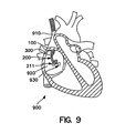
- FIG. 9-11 a particularly useful application for the system herein described is shown and is discussed below.
- a method for intravascularly deploying the system into the coronary sinus, obtaining an occlusive venogram, and accurately subselecting a venous branch and placing a cardiac lead therein is described.
- balloon catheter 200 is inserted within the lumen 104 of outer sheath 100 to create a sheath/catheter combination.
- a deflection mechanism 300 is advanced into the large lumen 208 of the balloon catheter via proximal port 218 so that the distal tip 308 of the deflection mechanism shaft 308 is generally disposed in balloon catheter shaft 202 near shaft distal tip 216 as previously described. This creates a combination sheath/catheter/deflection mechanism system as shown in Figure 5.
- a portion of shaft 202 will extend out through and beyond the lumen 104 at the sheath 100 distal end 112 for some length.
- This three-component system is introduced into the patient's venous system through the cephalic, subclavian or femoral vein via a conventional introducer as known to those of skill in the art.
- the physician uses the introducer to dilate the selected vein and then advance the system through the introducer into the selected vein.
- the physician navigates the three-component system through the vasculature to and through the superior vena cava 910 or inferior vena cava 940 (see Figure 9) and into the heart 900 right atrium 920.
- the distal tip 216 of shaft 202 and distal balloon 211 engage the coronary sinus ostium.
- the deflection mechanism is used to help steer the shaft 202 distal tip 216 into place.
- Balloon 211 is then inflated, and contrast is injected into the coronary veins through the distal port 214 of shaft 202. This creates an occlusive venogram for visualizing the coronary veins in advance of placing the lead in the desired location.
- the outer sheath 100 is advanced into the coronary sinus over the catheter shaft 202 so that it may be available as a conduit for lead placement. Once the sheath 100 is in place, the balloon 211 is deflated and the balloon catheter 200 and the associated deflection mechanism 300 are proximally withdrawn from sheath 100, leaving sheath 100 alone in place in the coronary sinus as shown in Figure 10.
- the micro-deflection mechanism 400 is placed into a central lumen of a lead 600 so that the deflectable distal section of micro-deflection mechanism 400 generally engages the distal section of the lead 600.
- the combination of these components is then advanced into the lumen 104 of sheath 100 and into the coronary sinus ostium as seen in Figure 11. From here, the physician will activate the deflection mechanism to steer the lead/micro-deflection mechanism combination.
- the micro-deflection mechanism may be used to subselect a venous branch into which the lead is to be permanently placed.
- the particular deflection shape and characteristics of micro-deflection mechanism have been selected by the physician for optimal use in navigating the venous system and creating the shape for the lead to assume during lead placement.
- the RHV 118 is removed from the sheath and slid over the lead connector (alternatively, RHV 118 may be split).
- RHV 118 may be split.
- the sheath 100 and hub 114 are split along score 126 as the sheath is pulled away from the lead 600 and removed from the body.
- Micro-deflection mechanism 400 may be withdrawn from the lead 600, after which the lead 600 is the only component left in the body. Lead 600 remains in place, and may be coupled to a pulse generator, cardioverter/defibrillator, drug delivery device, or another type of IMD.
- the method outlined above is merely exemplary of one way to deploy a cardiac lead according to the present invention. Many alternative applications for the invention are possible. Significant variations from this technique may occur within the scope of the present invention.
- the deflection mechanism that is adapted to be inserted within the balloon catheter is a steerable catheter such as an electrophysiology (EP) catheter.
- a catheter having a suitable steering mechanism is the Marinr catheter commercially available from Medtronic Corporation.
- Figure 12 is a plan view of a steerable catheter that may be used to navigate the balloon catheter 200 into the coronary sinus.
- the catheter 1000 is an anatomically-conforming, dual curve EP catheter used to sense electrical signals in the heart and associated vasculature.
- the catheter includes a shaft 1004 having an atraumatic distal end 1006 and a proximal end 1008.
- Shaft 1004 may have an outside diameter of less than approximately 0.06 inches (1.524 mm) and a length of about 50 mm to 110 mm.
- Proximal end 1008 is mounted to a handle 1010 having axially slidable manipulator rings 1012 and 1013, and a rotatable lateral deflection ring 1014 operably connected to proximal and distal manipulator wires carried by the body of the catheter.
- Sliding manipulator rings 1012 and 1013 cause a deflectable tip 1020 of catheter shaft 1004 to deflect as shown in FIGS. 12A and 12B between, for example, the solid-line and dashed-line positions of FIG. 12B.
- Rotating ring 1014 causes lateral deflection of tip 1020 through the torquing action of a core wire as shown in Figures 12C.
- a steerable EP catheter of the type shown in Figures 12 through 12C is adapted to be inserted within the inner lumen of the balloon catheter, which in turn, is inserted within the lumen 104 of the outer sheath 100 to create an alternative sheath/catheter combination.
- this assembly may be advanced into the chambers of the heart.
- the EP catheter distal tip may be advanced beyond the distal end of the outer sheath to guide the balloon catheter into the coronary sinus.
- the range of motion provided by the steerable catheter as noted above makes it particularly suitable for cannulating the coronary sinus and utilizing the balloon catheter to obtain a venogram in the manner discussed above.
- the balloon catheter and the steerable catheter are removed from the sheath so that the sheath may be used to place an IMD with a microdeflection mechanism in the manner discussed above.
- the system described herein may be used for deploying a wide array of devices in the coronary venous structure, the pulmonary venous structure, or any organ with large enough vessels for the introduction of the system.
- the system can be used in extravascular applications such as in the deployment of cochlear implants, in body cavities, muscle tissue, and the like.
- the balloon catheter 200 can be used for the introduction of drugs or other media or agents within a very discrete region of a vessel. Note that the balloon on the balloon catheter 200 described herein is optional.
- the deflectable catheter may be used without a balloon, for improved access and maneuverability.
- micro-deflection mechanism 400 due to its ability to be scaled to a very small size, it may be used for interventions into the spinal column, tiny vessels in the brain, liver, kidney, or any other suitable organ.
- sensors such as electrodes for recording signals and possibly ablating tissue may be incorporated into the micro-deflection mechanism 400.
- Fiber optics for the introduction of light for visualization or optical recording or sensing may be incorporated into either deflection mechanism.
- the deflection mechanism may also be used to deliver drugs or other therapeutic or diagnostic agents or materials as described above.
Landscapes
- Health & Medical Sciences (AREA)
- Life Sciences & Earth Sciences (AREA)
- Engineering & Computer Science (AREA)
- Heart & Thoracic Surgery (AREA)
- Veterinary Medicine (AREA)
- Animal Behavior & Ethology (AREA)
- Biomedical Technology (AREA)
- Public Health (AREA)
- General Health & Medical Sciences (AREA)
- Hematology (AREA)
- Anesthesiology (AREA)
- Pulmonology (AREA)
- Biophysics (AREA)
- Mechanical Engineering (AREA)
- Vascular Medicine (AREA)
- Cardiology (AREA)
- Nuclear Medicine, Radiotherapy & Molecular Imaging (AREA)
- Radiology & Medical Imaging (AREA)
- Media Introduction/Drainage Providing Device (AREA)
Abstract
Description
- This invention relates generally to a deflection mechanism for delivery of various devices or agents into a targeted area of the body according to the preamble of
claim 1. Such devices are for example known from US-5 824 031. More particularly, this invention relates to a visualization and delivery system for accurately placing devices such as leads, electrophysiology catheters, and therapeutic agents into large-organ vessel systems such as the coronary vasculature. - In treating conditions such as arrhythmia, one technique is to destroy or damage heart tissue that causes or is involved with the arrhythmia by suitably heating the tissue, e.g., by applying a laser beam or high-frequency electrical energy such as radio-frequency (RF) or microwave energy.
- For such treatment to be effective, the location of the tissue site causing or involved with the arrhythmia must be accurately determined in order to be able to contact heart tissue adjacent the desired location with a tissue-destroying device. A high degree of accuracy in determining this site is paramount so that an excessive amount of viable tissue is not destroyed adjacent the site. For example, the average arrhythmogenic site consists of about 1.4cm2 of endocardial tissue, whereas a re-entrant site might be much larger. RF ablation techniques produce lesions about 0.5 cm2 of diameter, so a number of lesions are typically generated in order to ablate the area of interest. If the site is not accurately mapped, much of the viable tissue surrounding the site will be unnecessarily destroyed.
- To determine the location of the tissue to be ablated, it is widely known to use elongated intravascular signal sensing devices that are advanced through the patient's vasculature until the distal portions of the device are disposed within one or more of the patient's heart chambers, with one or more electrodes on the distal portion of the device in contact with the endocardial lining. Such devices may also be advanced within a patient's coronary artery, coronary sinus, or cardiac vein. Sensing devices such as those disclosed in U.S. Patent No. 5,967,978 to Littmann et al., and combination sensing-ablation devices such as those disclosed in U.S. Patent No. 6,002,956 to Schaer are typical.
- Guiding catheters such as those disclosed in U.S. Patent Nos. 6,021,340 and 5,775,327 to Randolph et al. may be used to rapidly advance such devices into a patient's cardiac vein draining into the coronary sinus. A particular advantage of the catheters disclosed in these references is the presence of an inner lumen and distal port on the catheter shaft, which, in conjunction with a distal balloon, allows for the deployment of contrast fluid distal to the distal end of the catheter for visualizing the venous structure.
- The following U.S. Patents discuss related devices and methods for their use: U.S. Patent Nos. 5,509,411, 5,645,064, 5,682,885, 5,699,796, 5,706,809, and 5,701,298, each to Littmann et al; U.S. Patent Nos. 5,881,732 and 5,645,082, each to Sung et al; U.S. Patent No. 5,766,152 to Morely et al; U.S. Patent Nos. 5,782,760 and 5,863,291, each to Schaer; U.S. Patent No. 5,882,333 to Schaer et al., and U.S. Patent Number 6,122,552 to Tockman et al.
- However, despite the advantages of these sensing devices and guiding catheters, it remains quite difficult to accurately and reliably contact the various curved shapes one encounters in the endocardial lining. This is due to the frequent inability to customize the shape of their distal portion, or at least the inability to instantaneously and accurately adjust their shape upon demand during deployment to conform to the shape of the tissue of interest.
- Concerns similar to those described above are associated with the placement of leads within the heart and other areas of the coronary vasculature. For example, pacemakers, defibrillator/cardioverters, and other implantable medical device (IMDs) may employ one or more electrodes that are maintained in contact with a patient's heart muscle and through which electrical stimulation of the heart muscle is achieved. Such devices typically employ a flexible conductive lead that connects a remotely positioned and implanted power source to the one or more electrodes. Secure placement of the electrodes in the selected heart chamber (typically the right atrium) or in a coronary vein or artery is required to assure appropriate and reliable depolarization or "capture" of cardiac tissue by electrical stimuli delivered by the IMD.
- Many problems exist with reliably and accurately placing medical electrical leads and other similar devices such as catheters within the heart and associated vasculature.
- For instance, when placing transvenous leads or catheters, it is often difficult to engage the coronary sinus and sub-select the proper vessel into which the lead or catheter is to eventually be placed. Moreover, once placed, transvenous devices suffer from a relatively high rate of dislodgment from sites adjacent to, or on, the epicardium. Such dislodgement may result in a loss of capture or, at best, a reduction of the degree of electrical coupling between the electrode and the myocardium. More accurate and secure placement of the lead or catheter would not only reduce the difficulty and time associated with lead placement, but would reduce the risk of subsequent dislodgment as well.
- There thus is a need for a method and system for placing intralumenally-deployed devices such as electrophysiology catheters and leads into selected areas of the coronary vasculature in a highly accurate and reliable fashion.
- The invention thus provides a deflection mechanism as defined in
claim 1 and systems incorporating such a mechanism as defined in claims 11 and 16. - Preferred embodiments will now be described, by way of example only, with reference to the drawings
-
- Figure 1A is a side cutaway view of a delivery sheath of the present invention.
- Figure 1B is a cross-sectional view of a delivery sheath of the present invention.
- Figures 2A-2B are side and cross-sectional views, respectively, of a balloon catheter of the present invention.
- Figure 3 is as side view illustrating components included in both the deflection mechanism and micro-deflection mechanism of the present invention.
- Figures 4A-4B are various views of a deflection mechanism handle of the present invention.
- Figure 5 is a cross-sectional side view of three components of the present invention: a deflection mechanism, an outer sheath, and a balloon catheter with an inflated distal balloon and a deflected distal end.
- Figures 6A-6D are various views of a micro-deflection mechanism handle of the present invention.
- Figures 7A-7B are two embodiments of deflection and micro-deflection mechanisms detailing two notch configurations.
- Figures 8A-8D are additional embodiments of deflection and micro-deflection mechanisms of the present invention, detailing additional notch configurations.
- Figure 8E is a cross-sectional view of a deflection and micro-deflection mechanism having a tubular member with an irregular wall thickness to provide a preferred bending direction.
- Figures 9-11 depict a method for accurately placing an endocardial lead into the cardiac venous system through the coronary sinus ostium using a system of the present invention.
- Figure 12 is a plan view of a steerable catheter that may be used as an alternative deflection mechanism to navigate the
balloon catheter 200 into the coronary sinus. - Figures 12A through 12C illustrate various deflection positions of the distal tip of the steerable catheter of Figure 12.
- This invention is a system for intralumenal visualization and deployment of implantable medical devices (IMDs) such as transvenous leads, electrophysiology catheters and the like to various targeted regions of the body. The inventive system includes a sheath, a balloon catheter and associated deflection mechanism, and a micro-deflection device for highly accurate placement of the lead, catheter, or other device once the area of interest has been visualized.
- In the following pages we provide a component-by-component description of a preferred variation of the invention followed by a description of a procedure for using this system to place a transvenous lead into the coronary veins. Although we detail an exemplary set of system components and a method for its use, additional system configurations, some of which are also described herein, are within the scope of the invention.
- In general, the intralumenal visualization system and micro-deflection device of the present invention includes a deflectable catheter that includes an inflatable member such as a balloon, and is insertable into a lumen of a delivery sheath. This sheath may be inserted into the body via a typical introducer as will be described in more detail. In a preferred use, a balloon catheter is guided by a deflection mechanism so that it may engage the coronary sinus ostium so that an occlusive venogram may be rendered. The outer sheath then slides over the balloon catheter into the coronary sinus, and the balloon catheter is removed. Next, a lead with a micro-deflection mechanism is inserted into the sheath lumen so that the lead may be deployed at the desired location in the coronary veins. The micro-deflection mechanism disposed within the lead is used to provide rigidity to the lead and to allow a means to sub-select coronary vessels. The sheath preferably may be splittable along its longitudinal length so that it may be removed around the lead without disturbing it.
- Figure 1A is a cutaway side view depicting a variation of the delivery sheath described above. As best seen in Figure 1A,
sheath 100 comprises anelongate shaft 102 containing acentral lumen 104 throughout its length. The working length ofsheath 100 comprises adistal section 110 and aproximal section 120, each of which comprises a polymeric material having differing flexibilities as described below. Adistal end 112 ofsheath 100 disposed adjacentdistal section 110 also comprises the working length. - Near the proximal end of
sheath 100, ahub 114 may be affixed toproximal section 120 by an adhesive or other suitable means. We prefer an ultraviolet-curable adhesive sold by Loctite Corp. of Rocky Hill, Connecticut under the name UV 4201. We also prefer an adhesive sold by Dymax corp. of Trorrington, Connecticut under the trademark DYMAX.Hub 114 is made from any suitable medical-grade polymer, and is preferably injection molded and longitudinally scored or perforated so that it may be removed from around a device without disturbing that device. It may be molded in situ onto theproximal section 120 ofshaft 102. -
Hub 114 has an opening large enough to accommodate a special rotatable hemostatic valve (RHV) 118, to which it is detachably secured by, e.g. , an annular ring on thevalve 118 inner diameter. Acentral lumen 124 inRHV 118 is aligned and in fluid communication with the lumen ofshaft 102.Lumen 124 has a diameter large enough to accommodate a balloon catheter and a typical lead connector, such as an IS-1-type connector. An optional side arm (not shown) may be disposed onRHV 118 in fluid communication withlumen 124.RHV 118 may also be splittable via a scoring or perforation as described above. - An
annular polymeric collar 116 is disposed on the outside diameter of RHV 118 distal portion proximal to the point wherehub 114 meetsRHV 118. In this embodiment, rotation ofcollar 116 locks theRHV 118 to thehub 114. - Figure 1B is a cross-sectional view of the delivery sheath of Figure 1A. As shown in Figure 1B, a cross-section of
shaft 102 in thedistal section 110 revealsshaft lumen 104. The inner diameter ofshaft 102 will vary depending on the outer diameter of the balloon catheter and the lead, each of which should be capable of passing throughlumen 104. Typically the shaft inner diameter is between about 0.080 and 0.110 inch (2.032 and 2.794 mm), more preferably it is about 0.098 inch (2.489 mm). Likewise, the outer diameter ofshaft 102 is typically between about 0.090 and 0.130 inch (2.286 and 3.302 mm), more preferably it is about 0.118 inch (2.997 mm). We prefer the outer diameter ofshaft 102 to be as small as possible while still maintaining acceptable performance levels according to the application for which the shaft is used. We also prefer thatshaft 102 generally maintains a constant inner diameter throughout its length to provide a smooth and continuous step-free profile for the passage of various devices and materials therethrough as described herein. - Tubing comprising
distal section 110 andproximal section 120 will typically be polymeric, and is preferably any typical medical grade, biocompatible tubing with the appropriate performance characteristics as described herein. An especially desirable material is an extruded polyether block amide of the type sold by Atochem North America, Inc., Philadelphia, Pennsylvania under the trademark PEBAX. - Distal and
proximal sections shaft 102 preferably is composed of materials having two or more stiffnesses, althoughshaft 102, having a single stiffness value throughout its length is within the scope of the invention. - In one embodiment,
proximal section 120 comprises a relatively high stiffness material (typically about 72D) in comparison to the more flexible distal section 110 (typically about 40D). Although not shown in the view of Figure 1B,distal section 110 andproximal section 120 may be comprised of a DACRON (E.I. du Pont de Nemours and Company, Wilmington, DE) braid with a TEFLON (E.I. du Pont de Nemours and Company, Wilmington, DE) liner. The braid is surrounded by the PEBAX tubing as described above, which renders theproximal section 120 ofshaft 102 generally stiffer and less flexible thandistal portion 110. -
Distal end 112 is preferably a soft, atraumatic tip made from a relatively low stiffness polymeric material so to prevent injury to the intima of the vessel walls or to other tissue. We have found an effective material fordistal end 112. A material well-suited for the distal end is a thermoplastic polyurethane elastomer such as PELLETHANE (Dow Chemical Co., Midland, MI) or the like. - According to one embodiment of the invention,
distal portion 110 may be radiopaque. This can be achieved by the inclusion of radiopaque metals or their alloys into the structure, or more preferably by incorporating radiopaque powders such s BaSO, BiCO, etc. into the polymer comprisingdistal portion 110.Distal end 112 is preferably more radiopaque thandistal portion 110. This can be achieved by the incorporation of greater quantities of radiopaque powder, for instance, into the tubing, or by the use of a different material having greater radiopacity than that used indistal portion 110. This radiopaque feature allows the user to more readily visualize these portions ofsheath 100 under fluoroscopy. - The entire length of shaft 102 (from
distal end 112 to the far proximal end of RHV 118) is typically between about 40 and 60 cm, and is preferably about 55 cm.Distal end 112 may be between about 0.2 cm and 0.5 cm long, whiledistal section 110 is generally between about 5 and 10 cm long, and is preferably about 8 cm long.Proximal section 120 is between about 35 and 50 cm long; preferably about 42 cm. - Both the working length of
shaft 102 as well as the attachedhub 114 may contain a perforation or score 126 along their longitudinal axes. Alternatively, they may be otherwise configured to split so that they may be opened and removed from around an inserted device such as a lead or electrophysiology catheter without having to axially slide thesheath 100 relative to the device. A special tool may be used to facilitate such splitting, or the sheath/hub (and even RHV 114) combination may be split by hand without the aid of any special device. The splittable valve and sheath combinations as described in U.S. Patent No. 5,312,355 to Lee is exemplary. - Turning now to Figures 2A-2B, a
balloon catheter 200 of the present invention is shown in side view and distal cross-sectional view, respectively. This catheter is largely similar to the guiding catheters disclosed in U.S. Patent Nos. 6,021,340 and 5,775,327 to Randolph et al, as well as the VUEPORT family of balloon occlusion guiding catheters sold by Cardima, Inc. of Fremont Ca. -
Catheter 200 is designed to pass through thecentral lumen 104 ofdcdeployment sheath 100, and reach the therapeutic site as a combined unit withsheath 100 anddeflection mechanism 300. - As shown in Figures 2A and 2B,
balloon catheter 200 generally includes anelongated shaft 202, adistal shaft section 204, aproximal shaft section 206, and aninner lumen 208. Afemale luer lock 210 may be disposed on the proximal end ofshaft 202 and secured by asuitable adhesive 212, such as UV-curable Loctite 4201. - A
distal port 214 is provided in thedistal end 216 of the catheter shaft that is in fluid communication with theinner lumen 208. Proximal ofdistal end 216 is anocclusion balloon 211 axially disposed in thedistal section 204 aboutcatheter shaft 202. Thecatheter shaft 202 is provided with aninflation lumen 209 that extends through theshaft 202 to the interior of theballoon 211 to direct inflation fluid therein. - On the proximal end of
catheter 200, proximal toluer lock 210, is a multiarm adapter orhub 222 that terminates in a Y-adapter orhemostasis valve 232 and aproximal port 218 for passage of a deflection mechanism threrethrough as described later. - A first sidearm or
port 224 on adapter 222 (shown in partial cross section in Figure 2A) facilitates introduction of inflation fluid intoinflation lumen 209. Astopcock 228 onfirst sidearm 224 allows balloon 221 to stay inflated once the proper volume of fluid (such as air) has been introduced viasyringe 230.
Inflation lumen 209 is disposed inport 224 and extends distally intoshaft 224 to facilitate inflation ofballoon 211 as described above. - A second sidearm or
port 226 may also be disposed onhub 222, and may be in direct fluid communication with largeinner lumen 208.Inner lumen 208 is used for housing devices such as a deflection mechanism or the like. Onceballoon 211 is inflated, thesecond port 226 may be used for introducing contrast media or similar material throughlumen 208 and out thedistal port 214 for visualization of a section of interest in the body, such as an organ lumen or the cardiac venous system, for instance. - Not shown is a rotatable hemostatic valve (RHV) that may be housed in the
proximal center port 218 and that can accept devices such as a deflection mechanism described below. This RHV is capable of sealing onto the deflection mechanism to prevent fluid leakage and may be part of a duostat modified to comprise a single RHV and two sideports. Other configurations, of course, are possible. -
Shaft 202 ofballoon catheter 200 is of a sufficient size so that it may readily pass through thelumen 104 ofsheath 100. Ideally, we prefer the outer diameter ofshaft 202 to be between approximately 0.050 inch (1.27 mm) and 0.100 inch (2.54 mm). More preferably, it is between 0.060 inch (1.524 mm) and 0.080 inch (2.032 mm), and most preferably it is about 0.074 inch (1.88 mm). - The diameter of
inner lumen 208 preferably is large enough to allow free passage of contrast media or other material therethrough so that venograms and similar diagnostic procedures may be readily accomplished. It should also be large enough for the passage of a deflection mechanism as discussed below in greater detail. Finally,lumen 208 should allow the free passage of contrast media or other agents therethrough while occupied by a device such as a deflection mechanism. In general we prefer that inner lumen have a diameter of between 0.030 inch (0.762 mm) and 0.080 inches (2.032 mm), and is preferably about 0.048 inch (1.219 mm). Likewise,inflation lumen 209 preferably has a diameter of between about 0.005 inch (0.127 mm) and 0.020 inch (0.508 mm) and preferably is about 0.014 inch (0.356 mm). - The
balloon catheter shaft 202 preferably comprises PEBAX tubing having a durometer hardness of between about 60D and 80D, preferably about 72D. Preferably, shaftproximal section 206 has a heat shrink tubing disposed on the outer surface thereof. Preferably, this heat shrink tubing is polymeric and is comprised of clear polyolefin or the like.Distal tip 216 is preferably a soft, atraumatic tip made of a relatively flexible polymeric material similar in composition and stiffness todistal tip 112 ofsheath 100. In one embodiment, distal tip is radiopaque. - The working length of
balloon catheter shaft 202, which includes thedistal tip 216,distal section 204, andproximal section 206, should be between about 50 cm and 90 cm, although it may be longer or shorter depending upon the application. We especially prefer a working length of approximately 70 cm which can accommodate adistal tip 216 of approximately 0.5 cm, adistal section 204 of approximately 6 cm, and aproximal section 206 of approximately 63.5 cm. - The length of the
entire catheter 200 in this embodiment (the working length ofshaft 202 and the components disposed proximal ofproximal section 206 discussed above) should be about 77.5 cm. In general, we prefer that theballoon catheter shaft 202 be between about 15 cm and 20 cm longer thansheath 100. - Of course, the absolute and relative lengths of each component of
catheter 200 may vary considerably. The particular application in whichcatheter 200 and the entire system of the present invention is to be used will dictate the particular dimensions and materials for its various components (as well as each of the components of the inventive system) described herein. -
Occlusion balloon 211, when inflated, should have a diameter sufficient to seal the coronary sinus ostium. This inflated diameter will typically be between about 0.2 inch (5.08 mm) and 1.0 inches (25.4 mm), and more preferably, between about 0.4 inch (10.16 mm) and 0.8 inches (20.32 mm) We preferballoon 211 to comprise an inelastic or elastic polymeric material. Polyurethane (e.g. PELLETHANE 80A durometer, World Medical, Inc., Miami FL) is especially preferable. The inner diameter of theuninflated balloon 211 typicall will be between about 0.04 inch (1.016 mm) and 0.08 inches (2.032 mm), and more preferably between about 0.056 inch (1.422 mm) and 0.070 inches (1.778 mm). The balloon wall thickness typically will be between about 0.002 inch (0.05 mm) and 0.006 inches (0.152 mm), and more preferably about 0.004 inches (0.102 mm). Finally, theballoon 211 length typically will be between about 6mm and 14mm, and more preferably between about 8mm and 12mm. - The deflection mechanism and the micro-deflection mechanism are two separate components of the present invention.
Deflection mechanism 300 is designed for use in theballoon catheter 200, and is similar in many respects to themicro-deflection mechanism 400, only larger.Micro-deflection mechanism 400 is designed for use in a variety of applications where precise control and deflection of a device such as a lead, electrophysiology catheter, or other similar IMDs, is needed. Its small size relative todeflection mechanism 300 renders it useful in a wide range of applications in which its small size and flexibility may be relied upon. - Figure 3 is a plan view illustrating components of both the deflection and micro-deflection mechanisms, although it will be described in terms of the
deflection mechanism 300 for discussion purposes.Deflection mechanism 300 generally comprises aproximal section 304, adistal section 306, and a distal tip 308. Adjacent theproximal section 304 is handle 310, a preferred variation of which is shown in detail in Figures 4A and 4B. -
Deflection mechanism 300 is designed to be placed throughproximal port 218 of theballoon catheter 200 and into theinner lumen 208 such that the deflection mechanism distal tip 308 generally reachesdistal section 204, and preferablydistal tip 216, ofballoon catheter shaft 202. When thehandle 310 is activated, thedistal section 306 ofdeflection mechanism 300 deflects in a predetermined fashion, thus deflecting thedistal section 204 of the balloon catheter in a similar fashion. In this way, balloon catheter 200 (or any device into whichdeflection mechanism 300 is disposed) may be torqued to conform to the particular lumen or cavity into which it is disposed. -
Shaft 302 ofdeflection mechanism 300 comprises a tubular member such ashypotube 312, preferably made of metallic biocompatible material such as medical grade stainless steel, titanium, nitinol, alloys of these, or any suitable material as known to those of skill in the art.Hypotube 312 preferably has an outside diameter small enough to fit withininner lumen 208 ofcatheter 200 and is preferably less than 0.048 inch (1.219 mm). As shown in Figure 3,hypotube 312 is beveled to form astrain relief 316 at the distal end ofhypotube 312. Of course, this particular configuration ofhypotube 312, as well as other aspects of the Figure 3deflection mechanism 300, is merely exemplary. Other configurations that serve the purposes of this invention are within the scope of this disclosure as well. - Disposed within a central lumen of
hypotube 312 is apull wire 320, which can be a stainless steel, titanium, nitinol or other metal or alloy or even polymeric wire which when pulled activates the deflection ofdistal section 306 ofdeflection mechanism 300. Pullwire 320 is attached to aflat spring 322, which is disposed in thedistal section 306 ofdeflection mechanism 300.Spring 322 is attached to hypotube 312 using any suitable attachment method, such as welding, brazing, soldering, adhesives, or the like as is known to those of skill in the art.Spring 322 may be brazed to hypotube 312 alongbraze zone 314 as seen in Figure 3. Likewise, any similar suitable attachment techniques may be used to attachpull wire 320 tospring 322. In one embodiment, the pull wire and spring are brazed to one another inbraze zone 318 as seen in Figure 3. -
Distal deflection region 306 is preferably covered with compliant polymeric medical grade tubing, such as polyester, PEBAX, and tetrafluoroethylene. Especially preferred is a polymer of tetrafluoroethylene hexafluoropropylene and vinylidene fluoride known by its acronym as THV. This prevents fluid intrusion into the deflection mechanism. - In an especially useful variation of the invention in which the system is used for implanting a lead, the
balloon deflection mechanism 300 will be of sufficient diameter to provide rigidity to theballoon catheter 200 during introduction into the coronary sinus ostium. The curve reach and deflection range should be sufficient to provide easy introduction into the coronary sinus ostium, and the entire assembly should provide adequate pull strength to deflect and torque thedistal portion 204 ofballoon catheter shaft 202 during manipulation into the coronary sinus ostium. - Turning now to Figures 4A-4B, a useful variation of
handle 310 for manipulatingdeflection mechanism 300 is shown. Handle 310 includes body 324 andactivation mechanism 326.Activation mechanism 326 may be manipulated by pushing distally or pulling proximally along a longitudinal axis ofhandle 310. The machined parts of these components may be polymeric. For example, a thermoplastic such as the acetyl homopolymer DELRIN (E.I. du Pont de Nemours and Company, Wilmington, DE) may be used for this purpose. The molded parts may be formed of polymeric materials such as ABS (acrylonitrile butadiene styrene) or the like. A proximal end ofpull wire 320 is disposed in acentral lumen 328 ofhandle 310 and affixed into handle by means known to those of skill in the art. - Handle 310 is preferably lightweight and ergonomically configured for simple, one-handed operation. The deflection range (the maximum angular displacement the distal tip 308 undergoes when displaced from a straight and undeflected zero-degree position) may be between about 90 degrees and 180 degrees, preferably between about 100 degrees and 135 degrees. Further details of the features and versatility of
distal section 306 will be described in greater detail below, as well a detailed description of how deflection is achieved. - Figure 5 depicts three components of the inventive system described above in a partial cross-section.
Deflection mechanism 300 withhandle 310 is shown disposed in the inner lumen ofballoon catheter shaft 202 via theproximal port 218 as previously described. In turn, thecombination deflection mechanism 300 andballoon catheter 200 are disposed in thelumen 104 ofsheath 100. In Figure 5, the distal section ofballoon catheter shaft 202 is shown in a deflected state via the action of the hypotube/pull wire mechanism. Notice also thatdistal balloon 211 is inflated with fluid provided throughballoon fluid port 224. AnRHV 118 for outer peel-awaysheath 100 as discussed herein is seen as aflush port 130 disposed onRHV 118. For purpose of clarity,sheath hub 114 is not shown. - In general, there is no limit to the size of the deflection mechanisms described herein. All of the related components are readily scalable to larger or smaller sizes than those disclosed here as would be apparent to one of ordinary skill in the art and as the particular application demands.
- Turning now to a more specific discussion of
micro-deflection mechanism 400 depicted generally in Figure 3, the features of this element are largely similar to those ofdeflection mechanism 300. The features are generally smaller so that they may be used within devices such as leads, electrophysiology catheters, and the like as will be described below. - The micro-deflection mechanism utilizes a hypotube configuration as shown in Figures 7A, 7B, and 8A through 8E. We prefer the outer diameter of the micro-deflection mechanism hypotube (not shown) to be between about 0.012 inch (0.305 mm) and 0.030 inch (0.762 mm); preferably between about 0.014 inch (0.356 mm) and 0.026 inch (0.66 mm); most preferably about 0.015 inch (0.381 mm).
This will allow introduction of the hypotube into a conventional IS-1 lead connector, as well as allow for movement of the hypotube within the entire length of the central lumen of a lead body without causing any undue stress or damage to any of the lead or catheter components. - We also prefer that the
micro-deflection mechanism 400 pull wire, which is also preferably stainless steel or nitinol, have an outer diameter of between .005 and .015 inches (0.127 to 0.381 mm); and more preferably between about .006 and 0.010 inches (0.152 - 0.254 mm) Most preferably, the outer diameter is about 0.008 inch (0.203 mm). - During deflection, we prefer that the distal-most 10 mm to 30 mm of the
assembly 400 deflect, which in a preferred application, will allow the lead into whichassembly 400 is placed to engage the coronary sinus ostium. Due to the smaller size and greater maneuverability,assembly 400 may deflect through angles as high as 360 degrees and even 450 degrees or more. Such a high angular deflection capability allows the mechanism 400 (and the device into which it may be deployed) to create a tight loop. These high-angle deflections are especially useful in electrophysiology applications in which themicro-deflection mechanism 400 may be deployed in a mapping/ablation microcatheter to effect circumferential ablation patterns and the like in areas such as the cardiac pulmonary vein. - Figures 6A-6D depict various components of an especially useful variation of
micro-deflection mechanism 400 handle 414. As shown in Figure 6A, handle 414 includes abody 416 and anactivation mechanism 418 that may be manipulated by pushing distally or pulling proximally axially along a longitudinal axis ofhandle 310. The handle has a relatively small preferred length that may be in the range of 2 inches (5.08 mm). This scales well with the other, smaller components ofmicro-deflection mechanism 400, and also allows for simple, one-hand fingertip operation by a physician. Of course, the sizes may be sized as needed in a manner discussed above. -
Micro-deflection mechanism 400 can be used to replace the fixed-curve stylet generally used to provide a deflectable lead or catheter. This deflectable lead or catheter may be more precisely placed in the targeted region of the cardiac venous system, overcoming the problems of state-of-the-art systems. In addition, the micro-deflection mechanism may be used in conjunction with the other components of the inventive system describe herein for deflectable electrophysiological catheters. - Turning now to features that are common to both the
deflection mechanism 300 and micro-deflection mechanism 400 (hereinafter referred to in this generic discussion as simply "deflection mechanism"), each operates on the same principal based on a hypotube/pull wire assembly. The pull wire runs through the middle of the hypotube and is attached, via brazing or the like, at the distal end of the deflection mechanism. - The hypotube is allowed to deflect in a predetermined pattern by a series of slots, or kerfs, cut into the hypotube distal section. U.S. Patent Nos. 5,507,725 to Savage et al, 5,921,924 and 5,441,483 both to Avitall, 4,911,148 to Snowski et al, 5,304,131 to Paskar, describe various medical devices in which some type of notch is used to effect deflection devices in which some type of notch is used to effect deflection
- Figures 7 and 8 depict two variations of notch patterns that are useful in the present invention. Because of the scalability of these features, they are useful in both the
deflection assembly 300 as well asmicro-deflection assembly 400. - In reference to Figures 7 and 8, and the following discussion, note that due to the drawing space constraints, the "proximal section" of the hypotube refers to a portion of the deflection mechanism that is proximal only in that it is disposed proximal to the corresponding distal section. It is possible that a considerable length of the hypotubes depicted in Figures 7 and 8 exists proximal to the so-marked "proximal section".
- In Figures 7A and 7B, two hypotube/pull wire combinations are shown in top and side views, starting from the top of the page, respectively. Figure 7A depicts an
assembly 700 in which apull wire 704 is brazed, soldered, or otherwise affixed to the distal end ofhypotube 702 at hypotubedistal section 708. Note thatpull wire 704 is deployed insidehypotube 702. The pull wire is disposed in the interior ofhypotube 702 all the way to the hypotubedistal section 708 where it is affixed to hypotube 702 as described above. In general, pullwire 704 is affixed inhandle 310 such that when the handle is activated, hypotubedistal section 708 will deflect on the same side on which notches 710 (or as discussed below, the reduced wall thickness of hypotube) are located. - Each notch or
kerf 710 is progressively deeper as one moves from the proximal end 706 ofhypotube 702 to thedistal end 708. This particular feature will cause the hypotube to deflect in a smooth consistent curve. Note that the spacing betweennotches 710 is constant, and the only dimension of eachnotch 710 that changes its depth. The width remains constant. Each of these parameters may vary as performance requires. - Further, the centroids of each notch are aligned along a single, straight line longitudinal axis as one moves from proximal section 706 to
distal section 708. This axis along which the notches are aligned may be nonlinear. For instance, the axis may be sinusoidal to effect a serpentine deflection profile, with a constant or varying pitch, or the axis may have some other curvilinear or even stepwise shape. Regardless of whether the notch centroids are aligned along a linear or nonlinear axis, the centroid of each notch does not have to line up along such an axis. - Note also that the distance between adjacent notches as one moves from one end of a notch to the other end of hypotube of Figure 7A remains constant. That is, the longitudinal axes of the notches are parallel to one another. This aspect of the notches or kerfs may also change depending upon the application.
- Another variable that may affect the shape and performance characteristics of the
assembly 700 is the depth to which thenotches 710 are cut into the hypotube. For instance, in the assemblies of Figures 7A and 7B, the notches are cut completely through the wall thickness ofhypotube 702. This need not be the case. It is within the scope of the invention to provide notches inhypotube 702 in which a discrete amount of material is removed from the hypotube without penetrating through the hypotube thickness. A wide variety of depth profiles and patterns in etching each notch is therefore envisioned. - Taking this concept one step further, hypotube 702 need not contain a series of notches or kerfs to achieve the desired preferential distance deflection shape and response. For instance, it is within the scope of the invention to preferentially machine or etch the bulk of
hypotube 702 in an asymmetric fashion so that when thepull wire 704 is activated, thedistal section 708 ofhypotube 702 deflects in a predetermined pattern. In other words, the wall thickness ofhypotube 702 can be made to vary as a function of length and/or circumferential position in patterns ranging from a simple tapering pattern to complex patterns in which correspondingly intricate and complex deflection shapes and resources may be had. Such a concept can be used alone or in conjunction with the use of notches or kerfs as described herein. - Each of the parameters described above, as well as other parameters such as hypotube wall thickness, material selection, etc. may be chosen to effect a particular deflection pattern and response depending upon the application for which the hypotube/pull wire assembly (such as assembly 700) is intended. Furthermore, variations in many of these parameters from notch-to-notch may also be made. For instance, one notch may have a rectangular profile, while another notch on the same hypotube may have a circular profile, etc.
- Software may be utilized to aid the designer, by way of mathematical algorithms and the like, to ascertain the optimal profile for
hypotube 702 given a desired deflection shape, etc. For instance, a designer may be able to choose the application for which the assembly is to be used, and the software may select a number of alternative shapes from which the designer may choose. Once a deflection shape is chosen, the software will then calculate the optimal hypotube profile. - Figure 7B shows an
assembly 750 in which hypotube 752 and pullwire 754 are arranged in a similar fashion to those described above and shown in Figure 7A. The only difference in the assembly of Figure 7B is that the constant spacing between thenotches 756 is larger than that in the assembly of Figure 7A. This increased but constant spacing betweennotches 756 results inhypotube 752 being slightly heavier, since less material has been cut away from the hypotube. Whenassembly 750 is deflected, this means thatdistal section 760 will deflect through a smaller angle with a larger curve diameter (although the deflection shape will generally be similar to that of the deflectedassembly 700 due to the similar size, shape, and orientation of the notches in each assembly) than that experienced byassembly 700 in Figure 7A for a given deflection force. - Turning now to Figures 8A through 8E, additional variations of a notch pattern are shown (the pull wire is omitted for clarity). In Figure 8A, hypotube 810 with
proximal section 812 anddistal section 814 contains a series oflinear notches 816 similar to those of Figures 7A and 7B, except that each end ofnotches 816 contains asecondary notch 818 oriented generally perpendicular to notch 816. This notch design causes thedistal section 814 ofhypotube 810 to deflect in a similar fashion as described above, possibly with a tighter curve diameter. - The hypotube of Figure 8B is identical to that of Figure 8A, except that the notch pattern begins closer to the proximal section 822 of hypotube 820. A longer length of hypotube distal section 824 will therefore deflect when activated by the pull wire.
- Figure 8C is a plan view depicting an embodiment of deflection mechanism wherein the notches are arranged in a non-linear manner. For example, a sinusoidal pattern is depicted, although many other types of patterns are possible.
- Figure 8D is a plan view depicting an embodiment of deflection mechanism wherein the notches are of different shapes and sizes. For example, the notches may be circular, triangular, rectangular, or any other pattern desired to allow the deflection mechanism to assume a desired shape when tension is applied to the pull wire. The notches may all have a uniform shape and size, or alternatively, may have different shapes and/or sizes.
- Figure 8E is a cross-sectional view depicting an embodiment of the deflection member wherein the hypotube has walls that are not of a consistent thickness. The thinner region of the wall defines a preferred bending direction when tension is applied to the pull wire. In one embodiment, both a thinner wall thickness and the creation of notches in the thinner region may be used to provide the deflection mechanism in the hypotube or other tubular member.
- The notches or kerfs described herein and shown in the figures, as well as the varying wall thickness of the hypotube, may be created by any means know to those of skill in the art. They may be machines by traditional, laser, electron-discharge, or similar machining methods, they may be chemically etched, etched using known photolithographic techniques, etc.
- A particularly useful feature in the deflection mechanisms described herein is the active control feature of the deflection mechanism handle (both handle 310 as well as handle 414). Once the handle activation mechanism is engaged to deflect the distal section as described above, the deflection can be reversed only by the positive input of a user to disengage the same activation mechanism. In one embodiment of the deflection mechanism described above and shown in Figures 4A-4B and Figures 6A-6D, release of the
activation mechanisms distal section 306 will resume the undeflected state until the handle is activated once again. This feature allows the physician-user to manipulate other portions of the inventive system or to perform other tasks while thedistal section 204 ofballoon catheter 200, for example, remains in the intended deflected or undeflected state. Of course, it is within the scope of the invention to design the handle so that activation to deflect distal section is automatically reversed to return the distal portion to a default undeflected state. This may be accomplished by a bias spring or equivalent mechanism that activates when the physician releases the positive input causing the initial deflection. Such a design may also bias the distal end of the deflection mechanism to automatically reverse to a default deflected position. - Another feature common to both
handles 310 and 414 is the presence of one or more limit stops that may be built into the handle. These limit stops are designed to prevent over-deflection of the deflection mechanism. - Turning now to Figures 9-11, a particularly useful application for the system herein described is shown and is discussed below. In particular, a method for intravascularly deploying the system into the coronary sinus, obtaining an occlusive venogram, and accurately subselecting a venous branch and placing a cardiac lead therein is described.
- To prepare for the procedure,
balloon catheter 200 is inserted within thelumen 104 ofouter sheath 100 to create a sheath/catheter combination. Adeflection mechanism 300 is advanced into thelarge lumen 208 of the balloon catheter viaproximal port 218 so that the distal tip 308 of the deflection mechanism shaft 308 is generally disposed inballoon catheter shaft 202 near shaftdistal tip 216 as previously described. This creates a combination sheath/catheter/deflection mechanism system as shown in Figure 5. Typically, a portion ofshaft 202 will extend out through and beyond thelumen 104 at thesheath 100distal end 112 for some length. - This three-component system is introduced into the patient's venous system through the cephalic, subclavian or femoral vein via a conventional introducer as known to those of skill in the art. The physician uses the introducer to dilate the selected vein and then advance the system through the introducer into the selected vein.
- Typically under fluoroscopic guidance, the physician navigates the three-component system through the vasculature to and through the
superior vena cava 910 or inferior vena cava 940 (see Figure 9) and into theheart 900right atrium 920. At this point, thedistal tip 216 ofshaft 202 anddistal balloon 211 engage the coronary sinus ostium. The deflection mechanism is used to help steer theshaft 202distal tip 216 into place.Balloon 211 is then inflated, and contrast is injected into the coronary veins through thedistal port 214 ofshaft 202. This creates an occlusive venogram for visualizing the coronary veins in advance of placing the lead in the desired location. - Next, while
balloon 211 is still in the coronary sinus, theouter sheath 100 is advanced into the coronary sinus over thecatheter shaft 202 so that it may be available as a conduit for lead placement. Once thesheath 100 is in place, theballoon 211 is deflated and theballoon catheter 200 and the associateddeflection mechanism 300 are proximally withdrawn fromsheath 100, leavingsheath 100 alone in place in the coronary sinus as shown in Figure 10. - Next, the
micro-deflection mechanism 400 is placed into a central lumen of a lead 600 so that the deflectable distal section ofmicro-deflection mechanism 400 generally engages the distal section of thelead 600. The combination of these components is then advanced into thelumen 104 ofsheath 100 and into the coronary sinus ostium as seen in Figure 11. From here, the physician will activate the deflection mechanism to steer the lead/micro-deflection mechanism combination. In one embodiment, the micro-deflection mechanism may be used to subselect a venous branch into which the lead is to be permanently placed. Of course, the particular deflection shape and characteristics of micro-deflection mechanism have been selected by the physician for optimal use in navigating the venous system and creating the shape for the lead to assume during lead placement. - Once the
lead 600 is placed and the pacing thresholds are acceptable, theRHV 118 is removed from the sheath and slid over the lead connector (alternatively,RHV 118 may be split). Next, preferably with the aid of a special slitting tool such as a customized razor blade attached to thesheath 100, thesheath 100 andhub 114 are split alongscore 126 as the sheath is pulled away from thelead 600 and removed from the body. -
Micro-deflection mechanism 400 may be withdrawn from thelead 600, after which thelead 600 is the only component left in the body. Lead 600 remains in place, and may be coupled to a pulse generator, cardioverter/defibrillator, drug delivery device, or another type of IMD. - As discussed throughout the specification, the method outlined above is merely exemplary of one way to deploy a cardiac lead according to the present invention. Many alternative applications for the invention are possible. Significant variations from this technique may occur within the scope of the present invention.
- For example, in one embodiment, the deflection mechanism that is adapted to be inserted within the balloon catheter is a steerable catheter such as an electrophysiology (EP) catheter. One example of a catheter having a suitable steering mechanism is the Marinr catheter commercially available from Medtronic Corporation.
- Figure 12 is a plan view of a steerable catheter that may be used to navigate the
balloon catheter 200 into the coronary sinus. Thecatheter 1000 is an anatomically-conforming, dual curve EP catheter used to sense electrical signals in the heart and associated vasculature. The catheter includes ashaft 1004 having an atraumaticdistal end 1006 and aproximal end 1008.Shaft 1004 may have an outside diameter of less than approximately 0.06 inches (1.524 mm) and a length of about 50 mm to 110 mm.Proximal end 1008 is mounted to ahandle 1010 having axially slidable manipulator rings 1012 and 1013, and a rotatablelateral deflection ring 1014 operably connected to proximal and distal manipulator wires carried by the body of the catheter. Sliding manipulator rings 1012 and 1013 cause adeflectable tip 1020 ofcatheter shaft 1004 to deflect as shown in FIGS. 12A and 12B between, for example, the solid-line and dashed-line positions of FIG. 12B. Rotatingring 1014 causes lateral deflection oftip 1020 through the torquing action of a core wire as shown in Figures 12C. - A steerable EP catheter of the type shown in Figures 12 through 12C is adapted to be inserted within the inner lumen of the balloon catheter, which in turn, is inserted within the
lumen 104 of theouter sheath 100 to create an alternative sheath/catheter combination. As previously described, this assembly may be advanced into the chambers of the heart. Next, the EP catheter distal tip may be advanced beyond the distal end of the outer sheath to guide the balloon catheter into the coronary sinus. The range of motion provided by the steerable catheter as noted above makes it particularly suitable for cannulating the coronary sinus and utilizing the balloon catheter to obtain a venogram in the manner discussed above. Then the balloon catheter and the steerable catheter are removed from the sheath so that the sheath may be used to place an IMD with a microdeflection mechanism in the manner discussed above. - The system described herein may be used for deploying a wide array of devices in the coronary venous structure, the pulmonary venous structure, or any organ with large enough vessels for the introduction of the system. In addition, the system can be used in extravascular applications such as in the deployment of cochlear implants, in body cavities, muscle tissue, and the like.
- The
balloon catheter 200 can be used for the introduction of drugs or other media or agents within a very discrete region of a vessel. Note that the balloon on theballoon catheter 200 described herein is optional. The deflectable catheter may be used without a balloon, for improved access and maneuverability. - With respect to the
micro-deflection mechanism 400, due to its ability to be scaled to a very small size, it may be used for interventions into the spinal column, tiny vessels in the brain, liver, kidney, or any other suitable organ. In addition, sensors such as electrodes for recording signals and possibly ablating tissue may be incorporated into themicro-deflection mechanism 400. Fiber optics for the introduction of light for visualization or optical recording or sensing may be incorporated into either deflection mechanism. - The deflection mechanism may also be used to deliver drugs or other therapeutic or diagnostic agents or materials as described above.
Claims (19)
- A deflection mechanism for delivery of devices and agents into a targeted area of the body, the deflection mechanism comprising:a) a shaft (302) with a shaft lumen and a shaft wall comprising a proximal section, a proximal end, and a distal section with a distal tip, the distal section being capable of deflection;b) a pull wire assembly comprising a pull wire (320) running through the shaft lumen, said pull wire being attached to a spring (322) connected to the distal section of the shaft lumen; andc) a handle (310) disposed at the proximal end of said shaft lumen for manipulating said pull wire, the deflection mechanism capable of being removably inserted into a catheter lumen of an electrophysiology catheter and capable of deflecting the electrophysiology catheter; characterized in that the shaft is capable of deflecting in a predetermined pattern defined by a series of notches (710) in the shaft wall.
- The mechanism of claim 1, wherein the notches are equally-spaced.
- The mechanism of claim 1, wherein ones of the multiple notches each include an associated secondary notch.
- The mechanism of claim 3, wherein each of the ones of the multiple notches are substantially perpendicular to the associated secondary notch.
- The mechanism of claim 4, wherein the notches are substantially aligned along a longitudinal axis of the shaft.
- The mechanism of any preceding claim, wherein the notches have a similar shape with respect to one another.
- The mechanism of any of claims 1 to 5, wherein ones of the notches have a shape that is different from other ones of the notches.
- The mechanism of any preceding claim, wherein the shaft has a beveled distal end to provide strain relief.
- The deflection mechanism of claim 1, wherein shaft deflection is determined by a series of notches of progressively increasing depth from the proximal end to the distal tip.
- The deflection mechanism of claim 9, wherein shaft deflection is determined by reduced thickness of the shaft wall as a function of length, circumferential position, or length and circumferential position.
- A system for mammalian intralumenal visualization and delivery, said system comprising:a) a sheath (100) comprising an elongate member defining a lumen, said sheath comprising a proximal section (120) and a distal portion (110) with a distal end (112);b) a balloon catheter (200) comprising an inner balloon catheter lumen (209), an elongate shaft (202) with a flexible distal shaft section (204) and a proximal shaft section (206), a proximal port, a distal port in fluid communication with the catheter lumen, and an occlusion balloon (211) axially disposed about the distal shaft section, said deflectable balloon catheter capable of being removably inserted into the sheath;c) a deflection mechanism (300) as defined in any preceding claim, capable of being inserted into the inner balloon catheter lumen and deflecting the distal shaft section of the balloon catheter;d) an electrophysiology catheter (1000) comprising an elongate member defining an electrophysiology catheter lumen, a flexible tip disposed distally on the elongate member, and an electrode disposed on an outer surface of the tip, the electrophysiology catheter capable of being removably inserted into the sheath; ande) a microdeflection device (400) capable of being inserted into the electrophysiology catheter lumen and deflecting the tip of the electrophysiology catheter.
- The system of claim 11, wherein the electrophysiology catheter is an ablation catheter.
- The system of claim 12, wherein the sheath distal portion is more flexible than the sheath proximal section and wherein the sheath distal portion is radiopacque.
- The system of claim 11, wherein the deflection mechanism is a second steerable catheter.
- The system of claim 14, wherein the second steerable catheter is an electrophysiology catheter.
- A system for delivering an implantable medical device (IMD) to a body, comprising:a) a sheath (100) having an inner lumen;b) a catheter (200) having an inflation member and adapted to be slidably inserted within the sheath, the catheter having a catheter inner lumen;c) a deflection mechanism (300) as claimed in any of claims 1 to 10, adapted to be slidably inserted within the catheter and to cannulate the coronary sinus; andd) an assembly adapted to be slidably disposed within the sheath when the sheath is positioned within the coronary sinus, the assembly comprising an IMD inner lumen.
- The system of claim 16, wherein the IMD is a medical electrical lead.
- The system of claim 16, wherein the deflection mechanism is an electrophysiology (EP) catheter.
- The system of any of claims 16 to 18, wherein the sheath is splittable.
Applications Claiming Priority (3)
| Application Number | Priority Date | Filing Date | Title |
|---|---|---|---|
| US19369500P | 2000-03-31 | 2000-03-31 | |
| US193695P | 2000-03-31 | ||
| PCT/US2001/010456 WO2001072368A2 (en) | 2000-03-31 | 2001-03-30 | Intralumenal visualization system with deflectable mechanism |
Publications (2)
| Publication Number | Publication Date |
|---|---|
| EP1267986A2 EP1267986A2 (en) | 2003-01-02 |
| EP1267986B1 true EP1267986B1 (en) | 2006-05-10 |
Family
ID=22714647
Family Applications (1)
| Application Number | Title | Priority Date | Filing Date |
|---|---|---|---|
| EP01926523A Expired - Lifetime EP1267986B1 (en) | 2000-03-31 | 2001-03-30 | Deflection Mechanism |
Country Status (4)
| Country | Link |
|---|---|
| US (1) | US6743227B2 (en) |
| EP (1) | EP1267986B1 (en) |
| DE (1) | DE60119503T2 (en) |
| WO (1) | WO2001072368A2 (en) |
Families Citing this family (102)
| Publication number | Priority date | Publication date | Assignee | Title |
|---|---|---|---|---|
| US7497844B2 (en) | 2000-03-31 | 2009-03-03 | Medtronic, Inc. | System and method for positioning implantable medical devices within coronary veins |
| EP1513440A2 (en) * | 2002-05-30 | 2005-03-16 | The Board of Trustees of The Leland Stanford Junior University | Apparatus and method for coronary sinus access |
| US8956280B2 (en) | 2002-05-30 | 2015-02-17 | Intuitive Surgical Operations, Inc. | Apparatus and methods for placing leads using direct visualization |
| WO2004018031A2 (en) * | 2002-08-22 | 2004-03-04 | William A. Cook Australia Pty. Ltd. | Guide wire |
| US20040092844A1 (en) * | 2002-11-12 | 2004-05-13 | Johnson Eric T. | Guide catheter |
| US7655021B2 (en) * | 2003-03-10 | 2010-02-02 | Boston Scientific Scimed, Inc. | Dilator with expandable member |
| US7250041B2 (en) | 2003-03-12 | 2007-07-31 | Abbott Cardiovascular Systems Inc. | Retrograde pressure regulated infusion |
| US20050015048A1 (en) | 2003-03-12 | 2005-01-20 | Chiu Jessica G. | Infusion treatment agents, catheters, filter devices, and occlusion devices, and use thereof |
| US7655022B2 (en) * | 2003-04-28 | 2010-02-02 | Cardiac Pacemakers, Inc. | Compliant guiding catheter sheath system |
| US7056314B1 (en) | 2003-05-30 | 2006-06-06 | Pacesetter, Inc. | Steerable obturator |
| US20050101968A1 (en) * | 2003-11-12 | 2005-05-12 | Dadourian Daniel G. | Ostial locator device and methods for transluminal interventions |
| US7261730B2 (en) * | 2003-11-14 | 2007-08-28 | Lumerx, Inc. | Phototherapy device and system |
| US7481793B2 (en) * | 2003-12-10 | 2009-01-27 | Boston Scientic Scimed, Inc. | Modular steerable sheath catheters |
| US20070038283A1 (en) * | 2004-02-06 | 2007-02-15 | Mustapha Jihad A | Ostial stent and balloon |
| US7993350B2 (en) | 2004-10-04 | 2011-08-09 | Medtronic, Inc. | Shapeable or steerable guide sheaths and methods for making and using them |
| US9510732B2 (en) | 2005-10-25 | 2016-12-06 | Intuitive Surgical Operations, Inc. | Methods and apparatus for efficient purging |
| US8078266B2 (en) | 2005-10-25 | 2011-12-13 | Voyage Medical, Inc. | Flow reduction hood systems |
| US20080015569A1 (en) | 2005-02-02 | 2008-01-17 | Voyage Medical, Inc. | Methods and apparatus for treatment of atrial fibrillation |
| US11478152B2 (en) | 2005-02-02 | 2022-10-25 | Intuitive Surgical Operations, Inc. | Electrophysiology mapping and visualization system |
| US10064540B2 (en) | 2005-02-02 | 2018-09-04 | Intuitive Surgical Operations, Inc. | Visualization apparatus for transseptal access |
| US8137333B2 (en) | 2005-10-25 | 2012-03-20 | Voyage Medical, Inc. | Delivery of biological compounds to ischemic and/or infarcted tissue |
| WO2006122061A1 (en) * | 2005-05-06 | 2006-11-16 | Acumen Medical, Inc. | Complexly shaped steerable catheters and methods for making and using them |
| EP1906877A1 (en) * | 2005-05-23 | 2008-04-09 | Incept Llc | Apparatus and methods for locating an ostium of a vessel |
| WO2007038774A2 (en) * | 2005-09-30 | 2007-04-05 | Incept, Llc | Apparatus for locating an ostium of a vessel |
| US8221310B2 (en) | 2005-10-25 | 2012-07-17 | Voyage Medical, Inc. | Tissue visualization device and method variations |
| JP4912705B2 (en) * | 2006-03-17 | 2012-04-11 | 日本コヴィディエン株式会社 | Medical tube assembly |
| US7520876B2 (en) | 2006-04-21 | 2009-04-21 | Entellus Medical, Inc. | Device and method for treatment of sinusitis |
| US8657846B2 (en) | 2006-04-21 | 2014-02-25 | Entellus Medical, Inc. | Guide catheter and method of use |
| US8977333B2 (en) * | 2006-05-08 | 2015-03-10 | Cathrx Ltd | Shape-imparting mechanisms for catheter assemblies |
| US20070270679A1 (en) * | 2006-05-17 | 2007-11-22 | Duy Nguyen | Deflectable variable radius catheters |
| US7774051B2 (en) | 2006-05-17 | 2010-08-10 | St. Jude Medical, Atrial Fibrillation Division, Inc. | System and method for mapping electrophysiology information onto complex geometry |
| US9055906B2 (en) | 2006-06-14 | 2015-06-16 | Intuitive Surgical Operations, Inc. | In-vivo visualization systems |
| US20070299438A1 (en) * | 2006-06-23 | 2007-12-27 | Holzbaur Michael C | Torque transfer agent for introducer and method |
| US10004388B2 (en) | 2006-09-01 | 2018-06-26 | Intuitive Surgical Operations, Inc. | Coronary sinus cannulation |
| WO2008028149A2 (en) | 2006-09-01 | 2008-03-06 | Voyage Medical, Inc. | Electrophysiology mapping and visualization system |
| US20080097476A1 (en) | 2006-09-01 | 2008-04-24 | Voyage Medical, Inc. | Precision control systems for tissue visualization and manipulation assemblies |
| US10856904B2 (en) * | 2006-11-30 | 2020-12-08 | Medtronic, Inc. | Flexible introducer |
| US9084621B2 (en) | 2006-12-01 | 2015-07-21 | Boston Scientific Scimed, Inc. | Guide tube systems and methods |
| US9226648B2 (en) | 2006-12-21 | 2016-01-05 | Intuitive Surgical Operations, Inc. | Off-axis visualization systems |
| US8444637B2 (en) | 2006-12-29 | 2013-05-21 | St. Jude Medical, Atrial Filbrillation Division, Inc. | Steerable ablation device |
| US9220837B2 (en) | 2007-03-19 | 2015-12-29 | Insuline Medical Ltd. | Method and device for drug delivery |
| EP2131900B1 (en) | 2007-03-19 | 2018-05-30 | Insuline Medical Ltd. | Drug delivery device |
| US8622991B2 (en) | 2007-03-19 | 2014-01-07 | Insuline Medical Ltd. | Method and device for drug delivery |
| US8657805B2 (en) | 2007-05-08 | 2014-02-25 | Intuitive Surgical Operations, Inc. | Complex shape steerable tissue visualization and manipulation catheter |
| EP4233962A3 (en) | 2007-05-18 | 2023-09-06 | Boston Scientific Scimed, Inc. | Medical drive systems |
| US8409133B2 (en) | 2007-12-18 | 2013-04-02 | Insuline Medical Ltd. | Drug delivery device with sensor for closed-loop operation |
| US9173704B2 (en) * | 2008-06-20 | 2015-11-03 | Angiodynamics, Inc. | Device and method for the ablation of fibrin sheath formation on a venous catheter |
| US8257312B2 (en) * | 2008-07-30 | 2012-09-04 | Medtronic, Inc. | Integrated slitter for medical instrument inserter |
| US8007469B2 (en) * | 2008-07-30 | 2011-08-30 | Medtronic, Inc. | Medical instrument inserter |
| EP3088038B1 (en) * | 2008-09-05 | 2018-01-17 | C.R. Bard, Inc. | Balloon with radiopaque adhesive |
| BRPI0916125A2 (en) | 2008-11-07 | 2015-11-03 | Insuline Medical Ltd | "treatment device" |
| US9468364B2 (en) | 2008-11-14 | 2016-10-18 | Intuitive Surgical Operations, Inc. | Intravascular catheter with hood and image processing systems |
| US8372033B2 (en) | 2008-12-31 | 2013-02-12 | St. Jude Medical, Atrial Fibrillation Division, Inc. | Catheter having proximal heat sensitive deflection mechanism and related methods of use and manufacturing |
| US8821485B2 (en) * | 2009-01-29 | 2014-09-02 | Boston Scientific Scimed, Inc. | Employing a secondary sheath with an ablation catheter |
| GB0902339D0 (en) * | 2009-02-12 | 2009-04-01 | St Georges Healthcare Nhs Trus | Percutaneous guidewire |
| US8540662B2 (en) | 2009-03-24 | 2013-09-24 | St. Jude Medical, Atrial Fibrillation Division, Inc. | Medical devices having an atraumatic distal tip segment |
| CA2759817A1 (en) * | 2009-06-05 | 2010-12-09 | Entrigue Surgical, Inc. | Systems and devices for providing therapy of an anatomical structure |
| WO2011140535A1 (en) | 2010-05-07 | 2011-11-10 | Entellus Medical, Inc. | Sinus balloon dilation catheters and sinus surgury tools |
| US20120232563A1 (en) * | 2011-03-08 | 2012-09-13 | Medtronic, Inc. | Implant catheters for physiological pacing |
| US8845588B2 (en) | 2011-04-19 | 2014-09-30 | Medtronic Vascular, Inc. | Sheath introducer system with exchangeable hemostatic valves |
| BR112013030613B1 (en) * | 2011-06-03 | 2021-03-16 | C.R. Bard, Inc | non-compliant medical balloon |
| EP3603501A1 (en) | 2012-08-09 | 2020-02-05 | University of Iowa Research Foundation | Catheter systems for surrounding a tissue structure |
| US9713713B2 (en) | 2012-08-17 | 2017-07-25 | Cochlear Limited | Cochlear implant electrode assembly insertion tool |
| US9549666B2 (en) | 2012-11-10 | 2017-01-24 | Curvo Medical, Inc. | Coaxial micro-endoscope |
| US9233225B2 (en) | 2012-11-10 | 2016-01-12 | Curvo Medical, Inc. | Coaxial bi-directional catheter |
| US9173642B2 (en) | 2013-02-12 | 2015-11-03 | St. Jude Medical, Atrial Fibrillation Division, Inc. | Elongate medical device handle autolock |
| US9358042B2 (en) | 2013-03-13 | 2016-06-07 | The Spectranetics Corporation | Expandable member for perforation occlusion |
| US9248294B2 (en) | 2013-09-11 | 2016-02-02 | Medtronic, Inc. | Method and apparatus for optimization of cardiac resynchronization therapy using vectorcardiograms derived from implanted electrodes |
| EP3091921B1 (en) | 2014-01-06 | 2019-06-19 | Farapulse, Inc. | Apparatus for renal denervation ablation |
| EP3495018B1 (en) | 2014-05-07 | 2023-09-06 | Farapulse, Inc. | Apparatus for selective tissue ablation |
| WO2015192027A1 (en) | 2014-06-12 | 2015-12-17 | Iowa Approach Inc. | Method and apparatus for rapid and selective transurethral tissue ablation |
| WO2015192018A1 (en) | 2014-06-12 | 2015-12-17 | Iowa Approach Inc. | Method and apparatus for rapid and selective tissue ablation with cooling |
| EP3206613B1 (en) | 2014-10-14 | 2019-07-03 | Farapulse, Inc. | Apparatus for rapid and safe pulmonary vein cardiac ablation |
| US10105070B2 (en) | 2014-11-17 | 2018-10-23 | 3VO Medical, Inc. | Intrauterine access catheter for delivering and facilitating operation of a medical apparatus for assisting parturition |
| US10449336B2 (en) | 2015-08-11 | 2019-10-22 | The Spectranetics Corporation | Temporary occlusions balloon devices and methods for preventing blood flow through a vascular perforation |
| US10499892B2 (en) | 2015-08-11 | 2019-12-10 | The Spectranetics Corporation | Temporary occlusion balloon devices and methods for preventing blood flow through a vascular perforation |
| US10172673B2 (en) | 2016-01-05 | 2019-01-08 | Farapulse, Inc. | Systems devices, and methods for delivery of pulsed electric field ablative energy to endocardial tissue |
| US20170189097A1 (en) | 2016-01-05 | 2017-07-06 | Iowa Approach Inc. | Systems, apparatuses and methods for delivery of ablative energy to tissue |
| US10660702B2 (en) | 2016-01-05 | 2020-05-26 | Farapulse, Inc. | Systems, devices, and methods for focal ablation |
| US10130423B1 (en) | 2017-07-06 | 2018-11-20 | Farapulse, Inc. | Systems, devices, and methods for focal ablation |
| US10675443B2 (en) | 2016-03-07 | 2020-06-09 | St. Jude Medical, Cardiology Division, Inc. | Medical device including an actuator restraining assembly |
| EP3463563B1 (en) | 2016-05-31 | 2020-09-23 | Medtronic, Inc. | Electrogram-based control of cardiac resynchronization therapy |
| EP3471631A4 (en) | 2016-06-16 | 2020-03-04 | Farapulse, Inc. | Systems, apparatuses, and methods for guide wire delivery |
| US11207502B2 (en) | 2016-07-18 | 2021-12-28 | Scientia Vascular, Llc | Guidewire devices having shapeable tips and bypass cuts |
| US11350995B2 (en) | 2016-10-05 | 2022-06-07 | Nuvasive, Inc. | Surgical navigation systems and methods |
| US9987081B1 (en) | 2017-04-27 | 2018-06-05 | Iowa Approach, Inc. | Systems, devices, and methods for signal generation |
| US10617867B2 (en) | 2017-04-28 | 2020-04-14 | Farapulse, Inc. | Systems, devices, and methods for delivery of pulsed electric field ablative energy to esophageal tissue |
| CN111065327B (en) | 2017-09-12 | 2023-01-06 | 波士顿科学医学有限公司 | Systems, devices, and methods for ventricular focal ablation |
| US20190336198A1 (en) | 2018-05-03 | 2019-11-07 | Farapulse, Inc. | Systems, devices, and methods for ablation using surgical clamps |
| EP4461344A2 (en) | 2018-05-07 | 2024-11-13 | Boston Scientific Scimed, Inc. | Sytems, apparatuses, and methods for filtering high voltage noise induced by pulsed electric field ablation |
| CN112087980B (en) | 2018-05-07 | 2023-01-10 | 波士顿科学医学有限公司 | Systems, devices, and methods for delivering ablation energy to tissue |
| CN116327352A (en) | 2018-05-07 | 2023-06-27 | 波士顿科学医学有限公司 | Epicardial ablation catheter |
| JP2022501112A (en) | 2018-09-20 | 2022-01-06 | ファラパルス,インコーポレイテッド | Systems, devices, and methods for the delivery of pulsed field ablation energy to endocardial tissue |
| US11413454B2 (en) * | 2019-06-25 | 2022-08-16 | St. Jude Medical, Cardiology Division, Inc. | Delivery device having a deflectable and peelable mapping guide sheath for his bundle pacing |
| US11612440B2 (en) | 2019-09-05 | 2023-03-28 | Nuvasive, Inc. | Surgical instrument tracking devices and related methods |
| US10625080B1 (en) | 2019-09-17 | 2020-04-21 | Farapulse, Inc. | Systems, apparatuses, and methods for detecting ectopic electrocardiogram signals during pulsed electric field ablation |
| US11497541B2 (en) | 2019-11-20 | 2022-11-15 | Boston Scientific Scimed, Inc. | Systems, apparatuses, and methods for protecting electronic components from high power noise induced by high voltage pulses |
| US11065047B2 (en) | 2019-11-20 | 2021-07-20 | Farapulse, Inc. | Systems, apparatuses, and methods for protecting electronic components from high power noise induced by high voltage pulses |
| US10842572B1 (en) | 2019-11-25 | 2020-11-24 | Farapulse, Inc. | Methods, systems, and apparatuses for tracking ablation devices and generating lesion lines |
| CN111701138A (en) * | 2020-05-29 | 2020-09-25 | 广州新诚生物科技有限公司 | Multifunctional catheter and preparation method thereof |
| US20220105312A1 (en) * | 2020-10-05 | 2022-04-07 | Scientia Vascular, Llc | Microfabricated catheter devices with high axial strength |
| CN116490239A (en) | 2020-11-09 | 2023-07-25 | 敏捷设备有限公司 | Device for steering a catheter |
Family Cites Families (23)
| Publication number | Priority date | Publication date | Assignee | Title |
|---|---|---|---|---|
| US4215703A (en) | 1978-08-29 | 1980-08-05 | Willson James K V | Variable stiffness guide wire |
| US4813434A (en) * | 1987-02-17 | 1989-03-21 | Medtronic Versaflex, Inc. | Steerable guidewire with deflectable tip |
| US5312355A (en) | 1991-07-09 | 1994-05-17 | H L Medical Inventions, Inc. | Splittable hemostatic valve and sheath and the method for using the same |
| US5304131A (en) | 1991-07-15 | 1994-04-19 | Paskar Larry D | Catheter |
| US5584803A (en) * | 1991-07-16 | 1996-12-17 | Heartport, Inc. | System for cardiac procedures |
| US5855560A (en) * | 1991-11-08 | 1999-01-05 | Ep Technologies, Inc. | Catheter tip assembly |
| US5699796A (en) | 1993-01-29 | 1997-12-23 | Cardima, Inc. | High resolution intravascular signal detection |
| US5441483A (en) | 1992-11-16 | 1995-08-15 | Avitall; Boaz | Catheter deflection control |
| US5368564A (en) | 1992-12-23 | 1994-11-29 | Angeion Corporation | Steerable catheter |
| US5645082A (en) | 1993-01-29 | 1997-07-08 | Cardima, Inc. | Intravascular method and system for treating arrhythmia |
| US5706809A (en) | 1993-01-29 | 1998-01-13 | Cardima, Inc. | Method and system for using multiple intravascular sensing devices to detect electrical activity |
| NZ276573A (en) | 1993-11-01 | 1998-06-26 | Ericsson Telefon Ab L M | Cellular radio automatic retransmission request |
| US5921924A (en) | 1993-12-03 | 1999-07-13 | Avitall; Boaz | Mapping and ablation catheter system utilizing multiple control elements |
| US5882333A (en) | 1994-05-13 | 1999-03-16 | Cardima, Inc. | Catheter with deflectable distal section |
| US5782760A (en) | 1995-05-23 | 1998-07-21 | Cardima, Inc. | Over-the-wire EP catheter |
| US6002956A (en) | 1995-05-23 | 1999-12-14 | Cardima, Inc. | Method of treating using an over-the-wire EP catheter |
| US5658302A (en) | 1995-06-07 | 1997-08-19 | Baxter International Inc. | Method and device for endoluminal disruption of venous valves |
| JPH11507251A (en) | 1995-06-07 | 1999-06-29 | カーディマ・インコーポレイテッド | Guide catheter for coronary sinus |
| US6428489B1 (en) * | 1995-12-07 | 2002-08-06 | Precision Vascular Systems, Inc. | Guidewire system |
| US5824031A (en) | 1996-02-28 | 1998-10-20 | Cardio Source | Apparatus and method for deflecting a tip of a lead or catheter |
| US5863291A (en) | 1996-04-08 | 1999-01-26 | Cardima, Inc. | Linear ablation assembly |
| US5766152A (en) | 1996-08-15 | 1998-06-16 | Cardima, Inc. | Intraluminal delivery of tissue lysing medium |
| US6122552A (en) | 1999-03-03 | 2000-09-19 | Cardiac Pacemakers, Inc. | Insertion apparatus for left ventricular access lead |
-
2001
- 2001-03-30 EP EP01926523A patent/EP1267986B1/en not_active Expired - Lifetime
- 2001-03-30 DE DE60119503T patent/DE60119503T2/en not_active Expired - Lifetime
- 2001-03-30 US US09/822,678 patent/US6743227B2/en not_active Expired - Lifetime
- 2001-03-30 WO PCT/US2001/010456 patent/WO2001072368A2/en active IP Right Grant
Also Published As
| Publication number | Publication date |
|---|---|
| US6743227B2 (en) | 2004-06-01 |
| DE60119503D1 (en) | 2006-06-14 |
| US20010044624A1 (en) | 2001-11-22 |
| EP1267986A2 (en) | 2003-01-02 |
| WO2001072368B1 (en) | 2002-09-26 |
| WO2001072368A3 (en) | 2002-05-16 |
| DE60119503T2 (en) | 2007-04-19 |
| WO2001072368A2 (en) | 2001-10-04 |
Similar Documents
| Publication | Publication Date | Title |
|---|---|---|
| EP1267986B1 (en) | Deflection Mechanism | |
| US20190307988A1 (en) | System and method for positioning implantable medical devices within coronary veins | |
| US6836687B2 (en) | Method and system for delivery of a medical electrical lead within a venous system | |
| US6733500B2 (en) | Method and system for delivering a medical electrical lead within a venous system | |
| EP1471965B1 (en) | Inner and outer telescoping catheter delivery system | |
| US6616628B2 (en) | Steerable catheter with a longitudinally adjustable curved core | |
| EP1326550B1 (en) | Heart wall ablation/mapping catheter | |
| US7171275B2 (en) | High torque balloon catheter possessing multi-directional deflectability and methods thereof | |
| US20010039413A1 (en) | Preformed steerable catheter with movable outer sleeve and method for use | |
| CN112584737B (en) | Apparatus and accessory for percutaneous endoscopic access and ablation system | |
| WO1999030625A1 (en) | Left atrium ablation catheter and method | |
| US6235021B1 (en) | Ablation sheath | |
| EP1905376B1 (en) | Braided mesh catheter |
Legal Events
| Date | Code | Title | Description |
|---|---|---|---|
| PUAI | Public reference made under article 153(3) epc to a published international application that has entered the european phase |
Free format text: ORIGINAL CODE: 0009012 |
|
| 17P | Request for examination filed |
Effective date: 20021017 |
|
| AK | Designated contracting states |
Kind code of ref document: A2 Designated state(s): AT BE CH CY DE DK ES FI FR GB GR IE IT LI LU MC NL PT SE TR |
|
| AX | Request for extension of the european patent |
Free format text: AL;LT;LV;MK;RO;SI |
|
| RIN1 | Information on inventor provided before grant (corrected) |
Inventor name: KELLEY, JAMES, F. Inventor name: SERAJ, MAHMOUD Inventor name: CHAN, ERIC |
|
| 17Q | First examination report despatched |
Effective date: 20040312 |
|
| RBV | Designated contracting states (corrected) |
Designated state(s): DE FR |
|
| RAP1 | Party data changed (applicant data changed or rights of an application transferred) |
Owner name: MEDTRONIC, INC. |
|
| GRAP | Despatch of communication of intention to grant a patent |
Free format text: ORIGINAL CODE: EPIDOSNIGR1 |
|
| RTI1 | Title (correction) |
Free format text: DEFLECTION MECHANISM |
|
| GRAS | Grant fee paid |
Free format text: ORIGINAL CODE: EPIDOSNIGR3 |
|
| GRAA | (expected) grant |
Free format text: ORIGINAL CODE: 0009210 |
|
| AK | Designated contracting states |
Kind code of ref document: B1 Designated state(s): DE FR |
|
| RIN1 | Information on inventor provided before grant (corrected) |
Inventor name: KELLEY, JAMES, F. Inventor name: CHAN, ERIC Inventor name: SERAJ, MAHMOUD |
|
| REF | Corresponds to: |
Ref document number: 60119503 Country of ref document: DE Date of ref document: 20060614 Kind code of ref document: P |
|
| ET | Fr: translation filed | ||
| PLBE | No opposition filed within time limit |
Free format text: ORIGINAL CODE: 0009261 |
|
| STAA | Information on the status of an ep patent application or granted ep patent |
Free format text: STATUS: NO OPPOSITION FILED WITHIN TIME LIMIT |
|
| 26N | No opposition filed |
Effective date: 20070213 |
|
| REG | Reference to a national code |
Ref country code: FR Ref legal event code: PLFP Year of fee payment: 16 |
|
| PGFP | Annual fee paid to national office [announced via postgrant information from national office to epo] |
Ref country code: FR Payment date: 20160328 Year of fee payment: 16 |
|
| PGFP | Annual fee paid to national office [announced via postgrant information from national office to epo] |
Ref country code: DE Payment date: 20160331 Year of fee payment: 16 |
|
| REG | Reference to a national code |
Ref country code: DE Ref legal event code: R119 Ref document number: 60119503 Country of ref document: DE |
|
| REG | Reference to a national code |
Ref country code: FR Ref legal event code: ST Effective date: 20171130 |
|
| PG25 | Lapsed in a contracting state [announced via postgrant information from national office to epo] |
Ref country code: DE Free format text: LAPSE BECAUSE OF NON-PAYMENT OF DUE FEES Effective date: 20171003 Ref country code: FR Free format text: LAPSE BECAUSE OF NON-PAYMENT OF DUE FEES Effective date: 20170331 |