CN113299648A - Semiconductor device and method for manufacturing the same - Google Patents
Semiconductor device and method for manufacturing the same Download PDFInfo
- Publication number
- CN113299648A CN113299648A CN202010504218.6A CN202010504218A CN113299648A CN 113299648 A CN113299648 A CN 113299648A CN 202010504218 A CN202010504218 A CN 202010504218A CN 113299648 A CN113299648 A CN 113299648A
- Authority
- CN
- China
- Prior art keywords
- buried
- semiconductor device
- transistor
- conductive line
- source
- Prior art date
- Legal status (The legal status is an assumption and is not a legal conclusion. Google has not performed a legal analysis and makes no representation as to the accuracy of the status listed.)
- Pending
Links
- 239000004065 semiconductor Substances 0.000 title claims abstract description 180
- 238000000034 method Methods 0.000 title claims description 111
- 238000004519 manufacturing process Methods 0.000 title abstract description 5
- 239000000758 substrate Substances 0.000 claims abstract description 86
- 238000002955 isolation Methods 0.000 claims description 42
- 239000011229 interlayer Substances 0.000 claims description 12
- 239000010410 layer Substances 0.000 description 150
- 230000008569 process Effects 0.000 description 79
- 239000000463 material Substances 0.000 description 63
- 229910052751 metal Inorganic materials 0.000 description 45
- 239000002184 metal Substances 0.000 description 45
- 125000006850 spacer group Chemical group 0.000 description 32
- 230000004888 barrier function Effects 0.000 description 23
- 230000006870 function Effects 0.000 description 20
- 238000005229 chemical vapour deposition Methods 0.000 description 15
- 230000002829 reductive effect Effects 0.000 description 15
- 229910052581 Si3N4 Inorganic materials 0.000 description 12
- 238000000231 atomic layer deposition Methods 0.000 description 11
- 238000005530 etching Methods 0.000 description 11
- 238000000059 patterning Methods 0.000 description 11
- HQVNEWCFYHHQES-UHFFFAOYSA-N silicon nitride Chemical compound N12[Si]34N5[Si]62N3[Si]51N64 HQVNEWCFYHHQES-UHFFFAOYSA-N 0.000 description 11
- XUIMIQQOPSSXEZ-UHFFFAOYSA-N Silicon Chemical compound [Si] XUIMIQQOPSSXEZ-UHFFFAOYSA-N 0.000 description 10
- 150000004767 nitrides Chemical class 0.000 description 10
- 229910052710 silicon Inorganic materials 0.000 description 10
- 239000010703 silicon Substances 0.000 description 10
- 229910000577 Silicon-germanium Inorganic materials 0.000 description 9
- VYPSYNLAJGMNEJ-UHFFFAOYSA-N Silicium dioxide Chemical compound O=[Si]=O VYPSYNLAJGMNEJ-UHFFFAOYSA-N 0.000 description 8
- ATJFFYVFTNAWJD-UHFFFAOYSA-N Tin Chemical compound [Sn] ATJFFYVFTNAWJD-UHFFFAOYSA-N 0.000 description 8
- 230000008901 benefit Effects 0.000 description 8
- 230000015572 biosynthetic process Effects 0.000 description 8
- 229910044991 metal oxide Inorganic materials 0.000 description 8
- 150000004706 metal oxides Chemical class 0.000 description 8
- 229910052718 tin Inorganic materials 0.000 description 8
- -1 TaAlC Inorganic materials 0.000 description 7
- 238000001312 dry etching Methods 0.000 description 7
- 238000001039 wet etching Methods 0.000 description 7
- LEVVHYCKPQWKOP-UHFFFAOYSA-N [Si].[Ge] Chemical compound [Si].[Ge] LEVVHYCKPQWKOP-UHFFFAOYSA-N 0.000 description 6
- 230000005669 field effect Effects 0.000 description 6
- 229910052814 silicon oxide Inorganic materials 0.000 description 6
- 238000010276 construction Methods 0.000 description 5
- 229910052732 germanium Inorganic materials 0.000 description 5
- GNPVGFCGXDBREM-UHFFFAOYSA-N germanium atom Chemical compound [Ge] GNPVGFCGXDBREM-UHFFFAOYSA-N 0.000 description 5
- 238000004518 low pressure chemical vapour deposition Methods 0.000 description 5
- 239000002064 nanoplatelet Substances 0.000 description 5
- 229920002120 photoresistant polymer Polymers 0.000 description 5
- WFKWXMTUELFFGS-UHFFFAOYSA-N tungsten Chemical compound [W] WFKWXMTUELFFGS-UHFFFAOYSA-N 0.000 description 5
- 229910052721 tungsten Inorganic materials 0.000 description 5
- 239000010937 tungsten Substances 0.000 description 5
- JBRZTFJDHDCESZ-UHFFFAOYSA-N AsGa Chemical compound [As]#[Ga] JBRZTFJDHDCESZ-UHFFFAOYSA-N 0.000 description 4
- 229910052782 aluminium Inorganic materials 0.000 description 4
- XAGFODPZIPBFFR-UHFFFAOYSA-N aluminium Chemical compound [Al] XAGFODPZIPBFFR-UHFFFAOYSA-N 0.000 description 4
- 239000003989 dielectric material Substances 0.000 description 4
- 239000002019 doping agent Substances 0.000 description 4
- 239000012535 impurity Substances 0.000 description 4
- MRELNEQAGSRDBK-UHFFFAOYSA-N lanthanum(3+);oxygen(2-) Chemical compound [O-2].[O-2].[O-2].[La+3].[La+3] MRELNEQAGSRDBK-UHFFFAOYSA-N 0.000 description 4
- 239000007769 metal material Substances 0.000 description 4
- 238000005240 physical vapour deposition Methods 0.000 description 4
- 229910021420 polycrystalline silicon Inorganic materials 0.000 description 4
- 229910004490 TaAl Inorganic materials 0.000 description 3
- 229910008482 TiSiN Inorganic materials 0.000 description 3
- 239000003990 capacitor Substances 0.000 description 3
- 230000000295 complement effect Effects 0.000 description 3
- 238000000151 deposition Methods 0.000 description 3
- QRXWMOHMRWLFEY-UHFFFAOYSA-N isoniazide Chemical compound NNC(=O)C1=CC=NC=C1 QRXWMOHMRWLFEY-UHFFFAOYSA-N 0.000 description 3
- 238000005268 plasma chemical vapour deposition Methods 0.000 description 3
- 238000000623 plasma-assisted chemical vapour deposition Methods 0.000 description 3
- HBMJWWWQQXIZIP-UHFFFAOYSA-N silicon carbide Chemical compound [Si+]#[C-] HBMJWWWQQXIZIP-UHFFFAOYSA-N 0.000 description 3
- 239000002356 single layer Substances 0.000 description 3
- 238000004544 sputter deposition Methods 0.000 description 3
- 230000003068 static effect Effects 0.000 description 3
- RYGMFSIKBFXOCR-UHFFFAOYSA-N Copper Chemical compound [Cu] RYGMFSIKBFXOCR-UHFFFAOYSA-N 0.000 description 2
- 229910001218 Gallium arsenide Inorganic materials 0.000 description 2
- 229910004200 TaSiN Inorganic materials 0.000 description 2
- 229910010038 TiAl Inorganic materials 0.000 description 2
- FTWRSWRBSVXQPI-UHFFFAOYSA-N alumanylidynearsane;gallanylidynearsane Chemical compound [As]#[Al].[As]#[Ga] FTWRSWRBSVXQPI-UHFFFAOYSA-N 0.000 description 2
- 229910052802 copper Inorganic materials 0.000 description 2
- 239000010949 copper Substances 0.000 description 2
- 238000010586 diagram Methods 0.000 description 2
- 229910000449 hafnium oxide Inorganic materials 0.000 description 2
- WIHZLLGSGQNAGK-UHFFFAOYSA-N hafnium(4+);oxygen(2-) Chemical compound [O-2].[O-2].[Hf+4] WIHZLLGSGQNAGK-UHFFFAOYSA-N 0.000 description 2
- 239000012212 insulator Substances 0.000 description 2
- 238000005468 ion implantation Methods 0.000 description 2
- 150000002739 metals Chemical class 0.000 description 2
- 239000000203 mixture Substances 0.000 description 2
- RVTZCBVAJQQJTK-UHFFFAOYSA-N oxygen(2-);zirconium(4+) Chemical compound [O-2].[O-2].[Zr+4] RVTZCBVAJQQJTK-UHFFFAOYSA-N 0.000 description 2
- 238000000206 photolithography Methods 0.000 description 2
- 239000011295 pitch Substances 0.000 description 2
- 229920005591 polysilicon Polymers 0.000 description 2
- 229910010271 silicon carbide Inorganic materials 0.000 description 2
- 239000000126 substance Substances 0.000 description 2
- 238000000038 ultrahigh vacuum chemical vapour deposition Methods 0.000 description 2
- 238000000927 vapour-phase epitaxy Methods 0.000 description 2
- 229910001928 zirconium oxide Inorganic materials 0.000 description 2
- ITWBWJFEJCHKSN-UHFFFAOYSA-N 1,4,7-triazonane Chemical compound C1CNCCNCCN1 ITWBWJFEJCHKSN-UHFFFAOYSA-N 0.000 description 1
- ZOXJGFHDIHLPTG-UHFFFAOYSA-N Boron Chemical compound [B] ZOXJGFHDIHLPTG-UHFFFAOYSA-N 0.000 description 1
- 229910000530 Gallium indium arsenide Inorganic materials 0.000 description 1
- 229910000673 Indium arsenide Inorganic materials 0.000 description 1
- 229910020968 MoSi2 Inorganic materials 0.000 description 1
- 229910012990 NiSi2 Inorganic materials 0.000 description 1
- OAICVXFJPJFONN-UHFFFAOYSA-N Phosphorus Chemical compound [P] OAICVXFJPJFONN-UHFFFAOYSA-N 0.000 description 1
- 229910004012 SiCx Inorganic materials 0.000 description 1
- 229910004166 TaN Inorganic materials 0.000 description 1
- 229910004217 TaSi2 Inorganic materials 0.000 description 1
- 229910010037 TiAlN Inorganic materials 0.000 description 1
- 229910045601 alloy Inorganic materials 0.000 description 1
- 239000000956 alloy Substances 0.000 description 1
- 230000004075 alteration Effects 0.000 description 1
- 229910052785 arsenic Inorganic materials 0.000 description 1
- RQNWIZPPADIBDY-UHFFFAOYSA-N arsenic atom Chemical compound [As] RQNWIZPPADIBDY-UHFFFAOYSA-N 0.000 description 1
- QVGXLLKOCUKJST-UHFFFAOYSA-N atomic oxygen Chemical compound [O] QVGXLLKOCUKJST-UHFFFAOYSA-N 0.000 description 1
- 229910052796 boron Inorganic materials 0.000 description 1
- 239000002131 composite material Substances 0.000 description 1
- 150000001875 compounds Chemical class 0.000 description 1
- 239000002178 crystalline material Substances 0.000 description 1
- 230000003247 decreasing effect Effects 0.000 description 1
- 238000009792 diffusion process Methods 0.000 description 1
- 238000009713 electroplating Methods 0.000 description 1
- 238000005516 engineering process Methods 0.000 description 1
- 239000000945 filler Substances 0.000 description 1
- 230000009969 flowable effect Effects 0.000 description 1
- 239000007789 gas Substances 0.000 description 1
- PCHJSUWPFVWCPO-UHFFFAOYSA-N gold Chemical compound [Au] PCHJSUWPFVWCPO-UHFFFAOYSA-N 0.000 description 1
- 229910052737 gold Inorganic materials 0.000 description 1
- 239000010931 gold Substances 0.000 description 1
- 238000007654 immersion Methods 0.000 description 1
- 238000002513 implantation Methods 0.000 description 1
- RPQDHPTXJYYUPQ-UHFFFAOYSA-N indium arsenide Chemical compound [In]#[As] RPQDHPTXJYYUPQ-UHFFFAOYSA-N 0.000 description 1
- 230000000670 limiting effect Effects 0.000 description 1
- 229910052748 manganese Inorganic materials 0.000 description 1
- 230000000873 masking effect Effects 0.000 description 1
- 229910052752 metalloid Inorganic materials 0.000 description 1
- 150000002738 metalloids Chemical class 0.000 description 1
- 238000001451 molecular beam epitaxy Methods 0.000 description 1
- 239000002061 nanopillar Substances 0.000 description 1
- 239000002055 nanoplate Substances 0.000 description 1
- 239000002073 nanorod Substances 0.000 description 1
- 229910052760 oxygen Inorganic materials 0.000 description 1
- 239000001301 oxygen Substances 0.000 description 1
- 229910052698 phosphorus Inorganic materials 0.000 description 1
- 239000011574 phosphorus Substances 0.000 description 1
- 239000003870 refractory metal Substances 0.000 description 1
- 230000008439 repair process Effects 0.000 description 1
- 238000007789 sealing Methods 0.000 description 1
- 238000000926 separation method Methods 0.000 description 1
- 235000012239 silicon dioxide Nutrition 0.000 description 1
- 239000000377 silicon dioxide Substances 0.000 description 1
- 229910052709 silver Inorganic materials 0.000 description 1
- 239000007787 solid Substances 0.000 description 1
- 238000004528 spin coating Methods 0.000 description 1
- 238000006467 substitution reaction Methods 0.000 description 1
- 229910052719 titanium Inorganic materials 0.000 description 1
- 229910052726 zirconium Inorganic materials 0.000 description 1
- 229910021354 zirconium(IV) silicide Inorganic materials 0.000 description 1
Images


Classifications
-
- H—ELECTRICITY
- H01—ELECTRIC ELEMENTS
- H01L—SEMICONDUCTOR DEVICES NOT COVERED BY CLASS H10
- H01L23/00—Details of semiconductor or other solid state devices
- H01L23/52—Arrangements for conducting electric current within the device in operation from one component to another, i.e. interconnections, e.g. wires, lead frames
- H01L23/522—Arrangements for conducting electric current within the device in operation from one component to another, i.e. interconnections, e.g. wires, lead frames including external interconnections consisting of a multilayer structure of conductive and insulating layers inseparably formed on the semiconductor body
- H01L23/528—Layout of the interconnection structure
- H01L23/5286—Arrangements of power or ground buses
-
- H01L27/0924—
-
- H01L27/088—
-
- H—ELECTRICITY
- H01—ELECTRIC ELEMENTS
- H01L—SEMICONDUCTOR DEVICES NOT COVERED BY CLASS H10
- H01L21/00—Processes or apparatus adapted for the manufacture or treatment of semiconductor or solid state devices or of parts thereof
- H01L21/70—Manufacture or treatment of devices consisting of a plurality of solid state components formed in or on a common substrate or of parts thereof; Manufacture of integrated circuit devices or of parts thereof
- H01L21/71—Manufacture of specific parts of devices defined in group H01L21/70
- H01L21/74—Making of localized buried regions, e.g. buried collector layers, internal connections substrate contacts
- H01L21/743—Making of internal connections, substrate contacts
-
- H—ELECTRICITY
- H01—ELECTRIC ELEMENTS
- H01L—SEMICONDUCTOR DEVICES NOT COVERED BY CLASS H10
- H01L21/00—Processes or apparatus adapted for the manufacture or treatment of semiconductor or solid state devices or of parts thereof
- H01L21/70—Manufacture or treatment of devices consisting of a plurality of solid state components formed in or on a common substrate or of parts thereof; Manufacture of integrated circuit devices or of parts thereof
- H01L21/71—Manufacture of specific parts of devices defined in group H01L21/70
- H01L21/768—Applying interconnections to be used for carrying current between separate components within a device comprising conductors and dielectrics
- H01L21/76838—Applying interconnections to be used for carrying current between separate components within a device comprising conductors and dielectrics characterised by the formation and the after-treatment of the conductors
- H01L21/76895—Local interconnects; Local pads, as exemplified by patent document EP0896365
-
- H—ELECTRICITY
- H01—ELECTRIC ELEMENTS
- H01L—SEMICONDUCTOR DEVICES NOT COVERED BY CLASS H10
- H01L21/00—Processes or apparatus adapted for the manufacture or treatment of semiconductor or solid state devices or of parts thereof
- H01L21/70—Manufacture or treatment of devices consisting of a plurality of solid state components formed in or on a common substrate or of parts thereof; Manufacture of integrated circuit devices or of parts thereof
- H01L21/71—Manufacture of specific parts of devices defined in group H01L21/70
- H01L21/768—Applying interconnections to be used for carrying current between separate components within a device comprising conductors and dielectrics
- H01L21/76897—Formation of self-aligned vias or contact plugs, i.e. involving a lithographically uncritical step
-
- H01L21/823431—
-
- H01L21/823475—
-
- H01L21/823814—
-
- H01L21/823821—
-
- H01L21/823871—
-
- H—ELECTRICITY
- H01—ELECTRIC ELEMENTS
- H01L—SEMICONDUCTOR DEVICES NOT COVERED BY CLASS H10
- H01L23/00—Details of semiconductor or other solid state devices
- H01L23/48—Arrangements for conducting electric current to or from the solid state body in operation, e.g. leads, terminal arrangements ; Selection of materials therefor
- H01L23/482—Arrangements for conducting electric current to or from the solid state body in operation, e.g. leads, terminal arrangements ; Selection of materials therefor consisting of lead-in layers inseparably applied to the semiconductor body (electrodes)
- H01L23/485—Arrangements for conducting electric current to or from the solid state body in operation, e.g. leads, terminal arrangements ; Selection of materials therefor consisting of lead-in layers inseparably applied to the semiconductor body (electrodes) consisting of layered constructions comprising conductive layers and insulating layers, e.g. planar contacts
-
- H—ELECTRICITY
- H01—ELECTRIC ELEMENTS
- H01L—SEMICONDUCTOR DEVICES NOT COVERED BY CLASS H10
- H01L23/00—Details of semiconductor or other solid state devices
- H01L23/52—Arrangements for conducting electric current within the device in operation from one component to another, i.e. interconnections, e.g. wires, lead frames
- H01L23/522—Arrangements for conducting electric current within the device in operation from one component to another, i.e. interconnections, e.g. wires, lead frames including external interconnections consisting of a multilayer structure of conductive and insulating layers inseparably formed on the semiconductor body
- H01L23/5226—Via connections in a multilevel interconnection structure
-
- H—ELECTRICITY
- H01—ELECTRIC ELEMENTS
- H01L—SEMICONDUCTOR DEVICES NOT COVERED BY CLASS H10
- H01L23/00—Details of semiconductor or other solid state devices
- H01L23/52—Arrangements for conducting electric current within the device in operation from one component to another, i.e. interconnections, e.g. wires, lead frames
- H01L23/522—Arrangements for conducting electric current within the device in operation from one component to another, i.e. interconnections, e.g. wires, lead frames including external interconnections consisting of a multilayer structure of conductive and insulating layers inseparably formed on the semiconductor body
- H01L23/528—Layout of the interconnection structure
- H01L23/5283—Cross-sectional geometry
-
- H—ELECTRICITY
- H01—ELECTRIC ELEMENTS
- H01L—SEMICONDUCTOR DEVICES NOT COVERED BY CLASS H10
- H01L23/00—Details of semiconductor or other solid state devices
- H01L23/52—Arrangements for conducting electric current within the device in operation from one component to another, i.e. interconnections, e.g. wires, lead frames
- H01L23/535—Arrangements for conducting electric current within the device in operation from one component to another, i.e. interconnections, e.g. wires, lead frames including internal interconnections, e.g. cross-under constructions
-
- H01L27/0886—
-
- H01L21/823481—
Landscapes
- Engineering & Computer Science (AREA)
- Physics & Mathematics (AREA)
- Condensed Matter Physics & Semiconductors (AREA)
- General Physics & Mathematics (AREA)
- Computer Hardware Design (AREA)
- Microelectronics & Electronic Packaging (AREA)
- Power Engineering (AREA)
- Manufacturing & Machinery (AREA)
- Geometry (AREA)
- Insulated Gate Type Field-Effect Transistor (AREA)
- Metal-Oxide And Bipolar Metal-Oxide Semiconductor Integrated Circuits (AREA)
- Internal Circuitry In Semiconductor Integrated Circuit Devices (AREA)
Abstract
The present disclosure relates to a semiconductor device and a method of manufacturing the same. A device includes a transistor, an insulating structure, a buried conductive line, and a buried via. The transistor is over the substrate and includes a source/drain region and a source/drain contact over the source/drain region. An insulating structure is over the substrate and laterally surrounds the transistor. The buried conductive line is in the insulating structure and spaced apart from the transistor. A buried via is in the insulating structure and interconnects the transistor and the buried conductive line. The height of the buried conductive line is greater than the height of the source/drain contact.
Description
Technical Field
The present disclosure relates to a semiconductor device and a method of manufacturing the same.
Background
In the formation of integrated circuits, standard cells are often used as the basic elements for building integrated circuits. The standard cells are arranged and wired to form a functional circuit. In some arrangements of standard cells, the power rails are located on the boundaries of the cells. When a plurality of standard cells are arranged in a row, the power supply rails of the standard cells in the same row are connected to each other to form a long power supply rail, which may extend through, for example, thousands or more of standard cells. The power rails in adjacent rows are merged to form a power rail that is twice as wide as the power rails in the individual standard cells. For example, a VDD power rail of one row merges with another VDD power rail of an adjacent row, while a VSS power rail of one row merges with another VSS power rail of an adjacent row. Thus, with a circuit that includes multiple rows, the VDD power rail and the VSS power rail are arranged in an alternating pattern.
Disclosure of Invention
According to an embodiment of the present disclosure, there is provided a semiconductor device including: a transistor located over a substrate, wherein the transistor comprises: a source/drain region; and a source/drain contact located over the source/drain region; an insulating structure over the substrate and laterally surrounding the transistor; a buried conductive line in the insulating structure and spaced apart from the transistor; and a buried via in the insulating structure and interconnecting the transistor and the buried conductive line, wherein a height of the buried conductive line is greater than a height of the source/drain contact.
According to another embodiment of the present disclosure, there is provided a semiconductor device including: a transistor located over a substrate; an insulating structure over the substrate and laterally surrounding the transistor; a first conductive line over the insulating structure and the transistor; and a second conductive line located over the substrate and partially buried in the insulating structure, wherein the first and second conductive lines extend in a first direction, top surfaces of the first and second conductive lines are coplanar, and a height of the second conductive line is greater than a height of the first conductive line.
According to still another embodiment of the present disclosure, there is provided a method for manufacturing a device, including: forming a transistor over a substrate; forming a first trench in the substrate; forming an insulating structure over the substrate, surrounding the transistor and partially in the first trench; forming a second trench in the insulating structure, wherein the second trench does not expose the transistor; and forming a first buried conductive line in the second trench and adjacent to the transistor.
Drawings
Various aspects of this disclosure are best understood from the following detailed description when read with the accompanying figures. Note that in accordance with standard practice in the industry, various features are not drawn to scale. In fact, the dimensions of the various features may be arbitrarily increased or reduced for clarity.
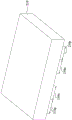
Fig. 1 is a schematic diagram of a perspective view of a layout structure corresponding to a semiconductor device, according to some embodiments of the present disclosure.
Fig. 2-12C illustrate methods for fabricating semiconductor devices at various stages according to some embodiments of the present disclosure.
Fig. 13A is a perspective view of a semiconductor device according to some embodiments of the present disclosure.
Fig. 13B is a sectional view taken along line B-B in fig. 13A.
Fig. 14A is a perspective view of a semiconductor device according to some embodiments of the present disclosure.
Fig. 14B is a sectional view taken along line B-B in fig. 14A.
Fig. 15A is a perspective view of a semiconductor device according to some embodiments of the present disclosure.
Fig. 15B is a sectional view taken along line B-B in fig. 15A.
Fig. 16A is a perspective view of a semiconductor device according to some embodiments of the present disclosure.
Fig. 16B is a sectional view taken along line B-B in fig. 16A.
Fig. 17A-20C illustrate methods for fabricating a semiconductor device at various stages according to some embodiments of the present disclosure.
Fig. 21A is a perspective view of a semiconductor device according to some embodiments of the present disclosure.
Fig. 21B is a sectional view taken along line B-B in fig. 21A.
Fig. 22A is a perspective view of a semiconductor device according to some embodiments of the present disclosure.
Fig. 22B is a sectional view taken along line B-B in fig. 22A.
Fig. 23A is a perspective view of a semiconductor device according to some embodiments of the present disclosure.
Fig. 23B is a sectional view taken along line B-B in fig. 23A.
Fig. 24A is a perspective view of a semiconductor device according to some embodiments of the present disclosure.
Fig. 24B is a sectional view taken along line B-B in fig. 24A.
Fig. 25A-28C illustrate methods for fabricating a semiconductor device at various stages according to some embodiments of the present disclosure.
Fig. 29 is a perspective view of a semiconductor device according to some embodiments of the present disclosure.
Fig. 30 is a perspective view of a semiconductor device according to some embodiments of the present disclosure.
Fig. 31 is a perspective view of a semiconductor device according to some embodiments of the present disclosure.
Fig. 32 is a perspective view of a semiconductor device according to some embodiments of the present disclosure.
Fig. 33 is a flow chart of a method for forming a semiconductor device in accordance with some embodiments of the present disclosure.
Detailed Description
The following disclosure provides many different embodiments, or examples, for implementing different features of the provided subject matter. Specific examples of components and arrangements are described below to simplify the present disclosure. Of course, these are merely examples and are not intended to be limiting. For example, in the description below, forming a first feature over or on a second feature may include embodiments in which the first and second features are formed in direct contact, and may also include embodiments in which additional features are formed between the first and second features such that the first and second features may not be in direct contact. Additionally, the present disclosure may repeat reference numerals and/or letters in the various examples. This repetition is for the purpose of simplicity and clarity and does not in itself dictate a relationship between the various embodiments and/or configurations discussed.
Furthermore, spatially relative terms, such as "under", "below", "beneath", "above", "upper" and the like, may be used herein for ease of description to describe one element or feature's relationship to another element(s) or feature(s) as illustrated. Spatially relative terms are intended to encompass different orientations of the device in use or operation in addition to the orientation depicted in the figures. The device may be otherwise oriented (rotated 90 degrees or at other orientations) and the spatially relative descriptors used herein interpreted accordingly.
As used herein, "near," "about," "approximately," or "substantially" shall generally mean within twenty percent, or ten percent or five percent of a given value or range. Numerical values set forth herein are approximate, meaning that the terms "proximate", "about", "approximately" or "substantially" can be inferred if not expressly stated.
The fins may be patterned by any suitable method. For example, the fins may be patterned using one or more photolithography processes, including double patterning or multiple patterning processes. Typically, double or multiple patterning processes combine lithographic and self-aligned processes, allowing for the creation of patterns with, for example, pitches smaller than those obtainable using a single direct lithographic process. For example, in one embodiment, a sacrificial layer is formed over a substrate and patterned using a photolithographic process. Spacers are formed alongside the patterned sacrificial layer using a self-aligned process. The sacrificial layer is then removed and the remaining spacers can then be used to pattern the fins.
The Gate All Around (GAA) transistor structure may be patterned by any suitable method. For example, the structure may be patterned using one or more photolithography processes, including double patterning or multiple patterning processes. Typically, double or multiple patterning processes combine lithographic and self-aligned processes, allowing for the creation of patterns with, for example, pitches smaller than those obtainable using a single direct lithographic process. For example, in one embodiment, a sacrificial layer is formed over a substrate and patterned using a photolithographic process. Spacers are formed alongside the patterned sacrificial layer using a self-aligned process. The sacrificial layer is then removed and the remaining spacers can then be used to pattern the GAA structure.
Some embodiments of the present disclosure relate to semiconductor devices having buried conductive line(s) to reduce chip size. Although some embodiments are shown below for finfets, it should be understood that the concept is not limited to finfets, but is also applicable to other types of devices, such as MOSFETs, HGAA devices, etc.
Fig. 1 is a schematic diagram of a perspective view of a layout structure corresponding to a semiconductor device 100, according to some embodiments of the present disclosure. In addition to the semiconductor device 100, fig. 1 also depicts X-axis, Y-axis, and Z-axis directions. Fig. 1 depicts a simplified version of a semiconductor device 100 to illustrate the general spatial relationship between various features; specific spatial relationships of various embodiments are discussed below with reference to fig. 2-32.
As shown in fig. 1, the semiconductor device 100 includes two transistors 110 and 120 having independent source and drain electrodes. Transistors 110 and 120 are adjacent to each other. In some embodiments, transistors 110 and 120 are disposed on a substrate (not shown) below transistors 110 and 120. In some embodiments, transistors 110 and 120 are planar structures. In some other embodiments, transistors 110 and 120 are finfets. In still other embodiments, transistors 110 and 120 may be formed at two nanoplatelets or a stack of two or more nanoplatelets (not shown) separated from each other along a vertical direction (e.g., along a Z-axis direction). In some embodiments, transistor 110 is a p-type FET and transistor 120 is an n-type FET, or vice versa, and thus, FET device 100 is a CFET device. The substrate underlying transistors 110 and 120 is any substrate suitable for epitaxial growth and/or is formed of any suitable crystalline material including, for example, silicon germanium (SiGe), and the like.
In some embodiments, the term "p-type FET" as described above is referred to as a FET that includes a p-type dopant (e.g., boron) in, for example, the doped source and drain regions of the p-type FET, and the term "n-type FET" as described above is referred to as a FET that includes an n-type dopant (e.g., phosphorus or arsenic) in, for example, the doped source and drain regions of the n-type FET.
The term "nanoplatelet" refers to a substantially two-dimensional material that is a single monolayer or a few monolayers thick, such that in some embodiments the thickness is from about 1 nanometer (nm) to about 100nm, and the lateral dimensions range from, for example, hundreds of nanometers to tens of micrometers. In some embodiments, the nanoplatelets or nanoplatelet stacks define defined (MD) segments of the metalloid.
In fig. 1, the transistor 110 includes a first source/drain 112, a gate 130, and a second source/drain 114 arranged in a horizontal direction (e.g., in a Y-axis direction). The gate 130 is disposed between the first and second source/drains 112 and 114 of the transistor 110, and extends in a predetermined direction (e.g., an X-axis direction). The gate 130 is configured to control a channel 116 between the first source/drain 112 and the second source/drain 114 of the transistor 110. In some embodiments, the channel 116 and the first and second source/drains 112, 114 are implemented by active regions formed by dopants.
The transistor 120 includes a first source/drain 122, a gate 130, and a second source/drain 124 arranged along a horizontal direction (e.g., along a Y-axis direction). In other words, the gate 130 is arranged as a common gate corresponding to the transistors 110 and 120, and the transistors 110 and 120 share the gate 130. Similarly, gate 130 is disposed between first source/drain 122 and second source/drain 124 of transistor 120. The gate 130 is configured to control the channel 126 between the first source/drain 122 and the second source/drain 124 of the transistor 120. In some embodiments, the channel 126 and the first and second source/drains 122 and 124 are implemented by active regions formed by dopants. Note that the configuration of transistors 110 and 120 in fig. 1 is illustrative, and should not limit the present disclosure. In some other embodiments, transistors 110 and 120 each include a gate.
In some embodiments, the term "source/drain" refers to a region that may be a source region or a drain region. Thus, to illustrate in fig. 1, when the first source/drain 112 of the transistor 110 is a source region, the second source/drain 114 of the transistor 110 is a drain region, and vice versa. Accordingly, when the first source/drain 122 of the transistor 120 is a source region, the second source/drain 124 of the transistor 120 is a drain region, and vice versa.
The structure of the semiconductor device 100 as described above is given for illustrative purposes. Various configurations of the semiconductor device 100 are within the intended scope of the present disclosure. For example, in various embodiments, the structure of semiconductor device 100 is extended to omit some conductive lines and/or buried conductive lines. The interconnections between the (buried) conductive lines and the transistors may be adjusted according to different layout designs.
With the structure of the semiconductor device 100 as described above, buried conductive lines 162, 164, 166, and/or 168 can be formed in the insulating structures 152 and 154 adjacent to the transistors 110 and 120, as shown in fig. 1. This reduces the chip area of the semiconductor device 100. Furthermore, due to the buried conductive lines 162, 164, 166, and/or 168 shown in fig. 1, the standard cells implementing the semiconductor device 100 can be scaled down.
The structure in fig. 1 can be applied to various types of devices to save chip area. Fig. 2-12C illustrate methods for fabricating semiconductor devices at various stages, according to some embodiments of the present disclosure. In some embodiments, the semiconductor devices shown in fig. 2-12C may be intermediate devices fabricated during the processing of an Integrated Circuit (IC) or a portion thereof, which may include Static Random Access Memory (SRAM), logic circuits, passive components (e.g., resistors, capacitors, and inductors), and/or active components (e.g., p-type field effect transistors (PFET), n-type FETs (nfet), multi-gate FETs, Metal Oxide Semiconductor Field Effect Transistors (MOSFET), Complementary Metal Oxide Semiconductor (CMOS) transistors, bipolar transistors, high voltage transistors, high frequency transistors), other memory cells, and combinations thereof.
Refer to fig. 2. A substrate 210 is provided. The substrate 210 includes at least one N-type region 210N and at least one P-type region 210P. At least one N-type device will be formed on N-type region 210N and at least one P-type device will be formed on P-type region 210P. For ease of illustration, it is assumed in fig. 2-12C that substrate 210 includes two N-type regions 210N and two P-type regions 210P adjacent to N-type regions 210N. In some embodiments, substrate 210 may comprise silicon (Si). Alternatively, substrate 210 may include germanium (Ge), silicon germanium (SiGe), gallium arsenide (GaAs), or other suitable semiconductor materials. In some embodiments, the substrate 210 may include a semiconductor-on-insulator (SOI) structure, such as a buried dielectric layer. Further alternatively, substrate 210 may include a buried dielectric layer, e.g., a Buried Oxide (BOX) layer, a buried dielectric layer formed by a method known as separation by implantation of oxygen (SIMOX) technique, wafer bonding, SEG, or other suitable method. In various embodiments, substrate 210 may comprise any of a variety of substrate structures and materials.
Refer to fig. 3. A plurality of semiconductor fins 212 and a plurality of semiconductor fins 214 are formed over the N-type region 210N and the P-type region 210P, respectively, of the substrate 210. The semiconductor fins 212 and 214 may serve as channel and source/drain features for the transistor. Note that the number of semiconductor fins 212 and 214 in fig. 3 is illustrative and should not limit the scope of the claimed invention. Additionally, one or more dummy fins may be disposed near both sides of the semiconductor fin 212 and/or the semiconductor fin 214 to improve pattern fidelity in the patterning process.
The semiconductor fins 212 and 214 may be formed, for example, by patterning and etching the substrate 210 using photolithographic techniques. In some embodiments, a layer of photoresist material (not shown) is deposited over the substrate 210. The layer of photoresist material is irradiated (exposed) according to a desired pattern, in this case the semiconductor fins 212 and 214, and developed to remove a portion of the photoresist material. The remaining photoresist material protects the underlying material from subsequent processing operations, such as etching. It should be noted that other masks, such as oxide or silicon nitride masks, may also be used in the etching process. The semiconductor fins 212 and 214 may be made of the same material as the substrate 210, and may extend or protrude continuously from the substrate 210. The semiconductor fins 212 and 214 may be intrinsic or appropriately doped with an n-type impurity or a p-type impurity.
In some other embodiments, the semiconductor fins 212 and 214 may be epitaxially grown. For example, exposed portions of an underlying material, such as exposed portions of the substrate 210, may be used in an epitaxial process to form the semiconductor fins 212 and 214. The shape of the semiconductor fins 212 and 214 may be controlled using a mask during an epitaxial growth process.
A plurality of isolation structures 220, such as Shallow Trench Isolations (STI), are formed in the substrate 210 to separate various devices. The formation of the isolation structure 220 may include etching a trench in the substrate 210 and filling the trench with an insulator material such as silicon oxide, silicon nitride, or silicon oxynitride. The filled trench may have a multi-layer structure such as a thermal oxide liner layer, wherein silicon nitride fills the trench. In some embodiments, isolation structure 220 may be created using the following process sequence: growing a pad oxide, forming a Low Pressure Chemical Vapor Deposition (LPCVD) nitride layer, patterning STI openings using photoresist and masking, etching trenches in the substrate 210 (to form the semiconductor fins 212 and 214), optionally growing a thermal oxide trench liner to improve the trench interface, filling the trenches with oxide, using Chemical Mechanical Planarization (CMP) to remove excess oxide, and recessing the thermal oxide trench liner and oxide to form the isolation structure 220 such that the tops of the semiconductor fins 212 and 214 protrude from the top surface of the isolation structure 220.
Refer to fig. 4. The interfacial layer 230 is conformally formed to cover the semiconductor fins 212, 214 and the isolation structure 220. In some embodiments, the interfacial layer 230 may comprise silicon dioxide, silicon nitride, a high- κ dielectric material, or other suitable material. In various examples, the interfacial layer 230 may be deposited by an ALD process, a CVD process, a sub-atmospheric CVD (sacvd) process, a flowable CVD process, a PVD process, or other suitable process. For example, the interface layer 230 may be used to prevent damage to the semiconductor fins 212 and 214 by subsequent processes (e.g., subsequent formation of dummy gate structures).
A gate structure 240 is formed over the interfacial layer 230, the semiconductor fins 212, 214, and the isolation structure 220. In some embodiments, a gate layer (not shown) may be formed over the interfacial layer 230 and then patterned to form the gate electrode 240. In some embodiments, the gate electrode 240 may be made of polysilicon (poly-Si), polycrystalline silicon germanium (poly-SiGe), or other suitable materials. If gate-first technology is employed, the gate structure 240 and the interface layer 230 are used as a gate electrode and a gate dielectric layer. Subsequently, as shown in fig. 4, portions of the interfacial layer 230 not covered by the gate structure 240 are removed to expose portions of the semiconductor fins 212 and 214.
Refer to fig. 5. Spacer structures 250 are formed on at least opposite sides of the gate structure 240 and the interfacial layer 230. The spacer structure 250 may include a sealing spacer and a primary spacer (not shown). Spacer structure 250 includes one or more dielectric materials, such as silicon oxide, silicon nitride, silicon oxynitride, SiCN, SiCxOyNzOr a combination thereof. A seal spacer is formed on the sidewalls of the gate structure 240 and a main spacer is formed on the seal spacer. The spacer structure 250 may be formed using a deposition method such as Plasma Enhanced Chemical Vapor Deposition (PECVD), Low Pressure Chemical Vapor Deposition (LPCVD), sub-atmospheric chemical vapor deposition (SACVD), and the like. The formation of the spacer structure 250 may include blanket forming a spacer layer and then performing an etching operation to remove horizontal portions of the spacer layer. The remaining vertical portions of the spacer layer form spacer structures 250.
Subsequently, a plurality of recesses 216 are formed on opposite sides of the gate structure 240 by etching the semiconductor fins 212 and 214 (see fig. 4). The gate structure 240 and gate spacers 250 are used as an etch mask in the formation of the recess 216. The etching process includes a dry etching process, a wet etching process, or a combination thereof.
Semiconductor material is then deposited in the recesses 216 to form epitaxial structures 262 and 264, referred to as source/drain regions. Epitaxial structures 262 are formed over the N-type regions 210N, respectively, and epitaxial structures 264 are formed over the P-type regions 210P, respectively. The epitaxial structures 262 and 264 may alternatively be referred to as raised source and drain regions. The semiconductor material includes a single element semiconductor material such as germanium (Ge) or silicon (Si), a compound semiconductor material such as gallium arsenide (GaAs) or aluminum gallium arsenide (AlGaAs), or a semiconductor alloy such as silicon germanium (SiGe) or gallium arsenide phosphide (GaAsP). Epitaxial structures 262 and 264 have a suitable crystallographic orientation (e.g., (100), (110), or (111) crystallographic orientation). In some embodiments, epitaxial structures 262 and 264 comprise source/drain epitaxial structures. In some embodiments, where an N-type device is desired, epitaxial structure 262 may include epitaxially grown silicon phosphide (SiP) or silicon carbide (SiC). In some embodiments, epitaxial structure 264 may comprise epitaxially grown silicon germanium (SiGe) in the case where a P-type device is desired. Epitaxial processes include CVD deposition techniques (e.g., Vapor Phase Epitaxy (VPE) and/or ultra-high vacuum CVD (UHV-CVD)), molecular beam epitaxy, and/or other suitable processes. The desired p-type or n-type impurities may or may not be doped during the epitaxial process. The doping may be achieved by an ion implantation process, a Plasma Immersion Ion Implantation (PIII) process, a gas and/or solid source diffusion process, other suitable processes, or a combination thereof.
Refer to fig. 6. A plurality of trenches 218 are formed in isolation structure 220 and substrate 210. For example, the trench 218 is formed between the gate structures 240 and substantially parallel to the semiconductor fins 212 and 214. In some embodiments, a mask layer is formed over the structure in fig. 5, and the mask layer is patterned to expose portions of the isolation structures 220 between the gate structures 240. These portions of isolation structures 220 are then removed to expose portions of substrate 210, and the exposed portions of the substrate are recessed to form trenches 218 therein. In some embodiments, the bottom surface 219 of the trench 218 is lower than the bottom surface 265 of the epitaxial structures 262 and/or 264. In some other embodiments, bottom surface 219 of trench 218 is higher than or substantially flush with bottom surface 265 of epitaxial structures 262 and/or 264.
Referring to fig. 7A and 7B, wherein fig. 7B is taken along line B-B in fig. 7AA cross-sectional view. A Contact Etch Stop Layer (CESL)270 is conformally formed over the structure of fig. 6. In some embodiments, CESL 270 may be one or more stress layers. In some embodiments, CESL 270 is tensile stressed and is made of Si3N4And (4) forming. In some other embodiments, CESL 270 includes a material such as oxynitride. In still other embodiments, CESL 270 may have a composite structure including multiple layers, such as a silicon nitride layer overlying a silicon oxide layer. CESL 270 may be formed using plasma enhanced cvd (pecvd), however, other suitable methods may be used, such as low pressure cvd (lpcvd), Atomic Layer Deposition (ALD), and the like.
A first interlayer dielectric (ILD)275 is then formed on the CESL 270. The first ILD 275 may be formed by Chemical Vapor Deposition (CVD), high density plasma CVD, spin coating, sputtering, or other suitable methods. In some embodiments, the first ILD 275 comprises silicon oxide. In some other embodiments, the first ILD 275 may comprise silicon oxynitride, silicon nitride, or a low-k material. Portions of the first ILD 275 are formed in the trenches 218 (see fig. 6).
Subsequently and optionally, a replacement gate (RPG) process scheme is optionally employed. In the RPG process scheme, a dummy polysilicon gate (in this case, gate structure 240 in fig. 6) is pre-formed and subsequently replaced with a metal gate. In some embodiments, the gate structure 240 is removed to form an opening, and the spacer structures 250 act as sidewalls of the opening. In some other embodiments, the interface layer 230 (see fig. 4) is also removed. The gate structure 240 (and the interfacial layer 230) may be removed by dry etching, wet etching, or a combination of dry etching and wet etching.
A gate dielectric layer 282 is formed in the opening and at least one metal layer is formed in the opening and on the gate dielectric layer 282. Subsequently, a Chemical Mechanical Planarization (CMP) process is performed to planarize the metal layer and the gate dielectric layer 282 to form a metal gate structure 280 in the opening. The metal gate structure 280 spans the semiconductor fins 212 and 214. The metal gate structure 280 includes a gate dielectric layer 282 and gold over the gate dielectric layer 282And a gate electrode 284. The metal gate electrode 284 may include a metal layer 285 (e.g., work function metal layer(s) and capping layer (s)), a fill layer(s) 286, and/or other suitable layers as desired in the metal gate stack. Workfunction metal layer 285 may comprise an n-type and/or p-type workfunction metal. Exemplary n-type work function metals include Ti, Ag, TaAl, TaAlC, TiAlN, TaC, TaCN, TaSiN, Mn, Zr, other suitable n-type work function materials, or combinations thereof. Exemplary p-type work function metals include TiN, TaN, Ru, Mo, Al, WN, ZrSi2、MoSi2、 TaSi2、NiSi2WN, other suitable p-type work function material, or combinations thereof. The work function metal layer 285 may have a plurality of layers. Work function metal layer(s) 285 may be deposited by CVD, PVD, electroplating, and/or other suitable processes. In some embodiments, the capping layer may comprise refractory metals and their nitrides (e.g., TiN, TaN, W)2N, TiSiN and TaSiN). The capping layer may be deposited by PVD, CVD, Metal Organic Chemical Vapor Deposition (MOCVD) ALD, or the like. In some embodiments, fill layer 286 may include tungsten (W). The fill layer 286 may be deposited by ALD, PVD, CVD, or other suitable process.
In fig. 7A and 7B, a plurality of devices are formed over a substrate 210. For example, the epitaxial structure 262, the semiconductor fin 212 (see fig. 3), and the metal gate structure 280 form an N-type device (transistor) TN, and the epitaxial structure 264, the semiconductor fin 214 (see fig. 3), and the metal gate structure 280 form a P-type device (transistor) TP.
Referring to fig. 8A and 8B, fig. 8B is a sectional view taken along line B-B in fig. 8A. The first ILD 275 is etched by various methods, including dry etching, wet etching, or a combination of dry etching and wet etching, to form a plurality of contact openings 276, a plurality of trenches 277a, 277b, 277c, and a plurality of interconnect openings 278. The contact opening 276 extends substantially vertically through the first ILD 275 to expose the epitaxial structures 262 and 264. The trenches 277a, 277b, 277c extend substantially vertically through the first ILD 275, but do not extend to the bottom-most surface of the first ILD 275. The trenches 277a, 277b, 277c do not expose the metal gate structure 280 and the epitaxial structures 262 and 264. The interconnect openings 278 extend from the trenches 277a to the respective contact openings 276. In some embodiments, the tops of the epitaxial structures 262 and 264 may be removed during the formation of the contact openings 276 and/or the interconnect openings 278. A plurality of patterning processes may be performed to form the contact openings 276, the trenches 277a, 277b, 277c, and the interconnect openings 278. For example, different mask layers are used to pattern the contact openings 276, trenches 277a, 277b, 277c, and interconnect openings 278, respectively.
Reference is made to fig. 9A and 9B, where fig. 9B is a sectional view taken along line B-B in fig. 9A. Source/drain contacts 292, bottom buried conductive lines 294, 295, 296, and buried vias 298 are formed in the contact openings 276, trenches 277a, 277B, 277c, and interconnect openings 278, respectively (see fig. 8A-8B). Each of the source/drain contacts 292, the bottom buried conductive lines 294, 295, 296, and the buried via 298 includes an optional barrier layer 292a, 294a, 295a, 296a, and 298a and a fill material 292b, 294b, 295b, 296b, and 298 b.
In some embodiments, barrier layers 292a, 294a, 295a, 296a, and 298A are formed in contact openings 276, trenches 277a, 277B, 277c, and interconnect openings 278, respectively (see fig. 8A and 8B). Barrier layers 292a, 294a, 295a, 296a, and 298a may improve adhesion between epitaxial structure 262/264 and the material (e.g., filler material) formed thereon. The barrier layers 292a, 294a, 295a, 296a and 298a may comprise a metal nitride material. For example, barrier layers 292a, 294a, 295a, 296a, and 298a comprise Ti, TiN, or a combination thereof. In some embodiments, barrier layers 292a, 294a, 295a, 296a, and 298a comprise a single layer or multiple layers. For a multi-layer construction, each layer includes a different composition of metal nitride from each other. For example, the barrier layers 292a, 294a, 295a, 296a and 298a have a first metal nitride layer including Ti and a second metal nitride layer including TiN.
Fill materials 292b, 294b, 295b, 296b, and 298b are formed in contact openings 276, trenches 277a, 277b, 277c, and interconnect openings 278 and over barrier layers 292a, 294a, 295a, 296a, and 298 a. Fill material 292b is electrically connected to epitaxial structures 262 and 264. In some embodiments, the openings may be filled with a metal material, and excess portions of the metal material and the barrier layer are removed by performing a planarization (e.g., CMP) process to form fill materials 292b, 294b, 295b, 296b, and 298b and barrier layers 292a, 294a, 295a, 296a, and 298 a. The fill materials 292b, 294b, 295b, 296b, and 298b may be made of tungsten, aluminum, copper, or other suitable material.
In fig. 9A and 9B, N-type devices (transistors) TN and P-type devices (transistors) TP are formed over N-type regions 210N and P-type regions 210P of substrate 210. A source/drain contact 292 is over the epitaxial structures 262 and 264 to interconnect the epitaxial structures 262 and 264. The bottom buried conductive line 294 is between the N-type devices TN, and the N-type devices TN and P-type devices TP are between the buried conductive lines 294 and 295 (or 296). The buried via 298 interconnects the bottom buried conductive line 294 and the two source/drain contacts 292 such that the bottom buried conductive line 294 is electrically connected to some of the epitaxial structures 262 and 264 of the N-type device TN and the P-type device TP. The first ILD 275 and the isolation structures 220 are referred to as insulating structures. The bottom buried conductive lines 294, 295, and 296 and the buried via 298 are embedded in insulating structures (i.e., the first ILD 275 and the isolation structure 220).
In fig. 9B, the top surfaces of the source/drain contacts 292, the bottom buried conductive lines 294, 295, 296, the buried via 298, and the first ILD 275 are substantially coplanar due to the planarization process described above. In some embodiments, the bottom surface 294c of the bottom buried conductive line 294 is lower than the top surface 222 of the isolation structure 220. Furthermore, in some embodiments, the bottom surfaces 295c and 296c of the bottom buried conductive lines 295 and 296 are lower than the top surface 222 of the isolation structure 220. The height H1 of each of the bottom buried conductive lines 294, 295, and 296 is greater than the height H2 of each of the source/drain contacts 292 (the metal gate structure 280 may also have a height H2). The bottom surface 298c of each of the buried vias 298 and the top surface 262d of the epitaxial structure 262 (and/or the top surface of the epitaxial structure 264) may be substantially coplanar. In fig. 9B, the barrier layers 292a, 294a, and 298a are connected to each other, and the filling materials 292B, 294B, and 298B are connected to each other, so that the source/drain contacts 292, the bottom buried conductive lines 294, and the buried via holes 298 shown in fig. 9B are electrically connected to each other.
Note that the source/drain contacts 292, bottom buried conductive lines 294, 295, 296, buried vias 298 may be formed in different processes. For example, the source/drain contacts 292 may be formed prior to forming the bottom buried conductive lines 294, 295, 296. Alternatively, the buried via 298 may be formed after the source/drain contact 292 and the bottom buried conductive lines 294, 295, 296 are formed.
Referring to fig. 10A and 10B, fig. 10B is a sectional view taken along line B-B in fig. 10A. A second interlayer dielectric (ILD)310 is then formed over the structure of fig. 9A. The second ILD 310 may be formed by Chemical Vapor Deposition (CVD), high density plasma CVD, spin-on, sputtering, or other suitable methods. In some embodiments, the second ILD 310 comprises silicon oxide. In some other embodiments, the second ILD 310 may comprise silicon oxynitride, silicon nitride, or a low-k material.
The second ILD 310 is then etched by various methods (including dry etching, wet etching, or a combination of dry etching and wet etching) to form a plurality of gate openings 314, a plurality of contact openings 316, a plurality of trenches 317a, 317b, 317c, and a plurality of interconnect openings 318, 312. Gate openings 314 extend substantially vertically through the second ILD 310 to expose the metal gate structures 280, respectively. Contact openings 316 extend substantially vertically through the second ILD 310 to expose the source/drain contacts 292, respectively. The trenches 317a, 317b, 317c extend substantially vertically through the second ILD 310, but do not extend to the bottom-most surface 311 of the second ILD 310. The trenches 317a, 317b, 317c may be located directly above the bottom buried conductive lines 294, 295, and 296. The interconnect openings 318 extend from the trenches 317b to the corresponding contact openings 316, and the interconnect openings 312 are under the trenches 317b and expose the buried conductive lines 295. A plurality of patterning processes may be performed to form the gate opening 314, the contact opening 316, the trenches 317a, 317b, 317c, and the interconnect openings 312, 318. For example, the gate opening 314, the contact opening 316, the trenches 317a, 317b, 317c and the interconnect openings 312, 318 are patterned separately using different mask layers.
Reference is made to fig. 11A and 11B, where fig. 11B is a sectional view taken along line B-B in fig. 11A. Gate via 321, source/drain contacts 322, top buried conductive lines 324, 325, 326, and buried vias 328 and 329 are formed in gate opening 314, contact opening 316, trenches 317a, 317B, 317c, and interconnect openings 312, 318 (see fig. 10A-10B), respectively. Each of the gate via 321, source/drain contact 322, top buried conductive line 324, 325, 326, and buried vias 328 and 329 includes an optional barrier layer 321a, 322a, 324a, 325a, 326a, 328a, and 329a and a fill material 321b, 322b, 324b, 325b, 326b, 328b, and 329 b.
In some embodiments, barrier layers 321a, 322a, 324a, 325a, 326a, 328a, and 329a are formed in gate opening 314, contact opening 316, trenches 317a, 317B, 317c, and interconnect openings 312, 318, respectively (see fig. 10A and 10B). Barrier layers 321a, 322a, 324a, 325a, 326a, 328a and 329a may comprise a metal nitride material. For example, barrier layers 321a, 322a, 324a, 325a, 326a, 328a, and 329a comprise Ti, TiN, or a combination thereof. In some embodiments, barrier layers 321a, 322a, 324a, 325a, 326a, 328a, and 329a comprise a single layer or multiple layers. For a multilayer construction, each layer includes a different composition of metal nitride from each other. For example, barrier layers 321a, 322a, 324a, 325a, 326a, 328a, and 329a have a first metal nitride layer including Ti and a second metal nitride layer including TiN.
Fill materials 321b, 322b, 324b, 325b, 326b, 328b, and 329b are formed in contact openings 276, trenches 277a, 277b, 277c, and interconnect openings 278 and over barrier layers 321a, 322a, 324a, 325a, 326a, 328a, and 329 a. Fill material 321b is electrically connected to metal gate structure 280, and fill material 322b is electrically connected to source/drain contacts 292. In some embodiments, a metal material may be filled in the opening, and an excess portion of the metal material and the barrier layer is removed by performing a planarization (e.g., CMP) process to form the filling materials 321b, 322b, 324b, 325b, 326b, 328b, and 329b and the barrier layers 321a, 322a, 324a, 325a, 326, 328a, and 329 a. Fill materials 321b, 322b, 324b, 325b, 326b, 328b, and 329b may be made of tungsten, aluminum, copper, or other suitable material.
In fig. 11B, the top surfaces of the gate via 321, the source/drain contact 322, the top buried conductive line 324, 325, 326, and the buried via 328 are substantially coplanar due to the planarization process described above. The height H3 of each of the top buried conductive lines 324, 325, and 326 is less than the height H4 of each of the source/drain contacts 322. In fig. 11B, the barrier layers 322a, 325a, 328a, and 329a are connected to each other, and the filling materials 322B, 325B, 328B, and 329a are connected to each other, so that one of the source/drain contacts 322, the top buried conductive line 325, the buried vias 328, 329, one of the source/drain contacts 292, and the bottom buried conductive line 295 shown in fig. 11B are electrically connected to each other.
Referring to fig. 12A-12C, fig. 12B is a sectional view taken along line B-B in fig. 12A, and fig. 12C is a sectional view taken along line C-C in fig. 12A. A third ILD 330 is then formed on the structure of figure 11A. The third ILD 330 may be formed by Chemical Vapor Deposition (CVD), high density plasma CVD, spin-on, sputtering, or other suitable methods. In some embodiments, the third ILD 330 comprises silicon oxide. In some other embodiments, the third ILD 330 may comprise silicon oxynitride, silicon nitride, or a low-k material.
A plurality of conductive lines 341, 343, 345, 347 and 349 are formed over the third ILD 330. In some embodiments, the formation of conductive lines 341, 343, 345, 347, and 349 includes a damascene process and may be electrically connected to N-type devices TN and/or P-type devices TP by forming vias in the third ILD 330. For example, conductive line 345 is coupled to gate structure 280 through via 352 and gate via 321, and/or conductive line 347 is coupled to epitaxial structures 262 and 264 through via 354 and source/ drain contacts 322 and 292. Note that the formation and/or configuration of conductive lines 341, 343, 345, 347 and 349 are examples and should not limit the present disclosure. In some embodiments, each of the conductive lines 341, 343, 345, 347, and 349 includes a barrier layer and a fill material over the barrier layer. In some embodiments, conductive lines 341 and 349 may be power supply lines and conductive lines 343, 345, and 347 may be signal lines. In some embodiments, width W1 of conductive line 349 is greater than width W2 of conductive line 347 (or 345 or 343). Conductive line 341 may be shared with cells adjacent to the structure shown in fig. 12A-12C, such that conductive line 341 may have a width substantially the same as width W1 of conductive line 349.
In fig. 12A-12C, since the semiconductor device includes top and/or bottom buried conductive lines 324, 325, 326, 294, 295, and/or 296, internal electrical connection between the N-type device TN and the P-type device TP may be achieved by using the top and/or bottom buried conductive lines 324, 325, 326, 294, 295, and/or 296. The top and/or bottom buried conductive lines 324, 325, 326, 294, 295, and/or 296 are directly below the conductive lines 341 and 349 (e.g., power supply lines) such that the top and/or bottom buried conductive lines 324, 325, 326, 294, 295, and/or 296 do not occupy a layout area of the semiconductor device. With this configuration, the number of conductive lines (e.g., conductive lines 341, 343, 345, 347 and 349) over the third ILD 330 may be reduced, and the cell height H5 of the semiconductor device may be reduced. Furthermore, the buried conductive lines 294, 295, and/or 296 have the benefit of relieving the stress or strain of the first ILD 275 (and isolation structures 220).
Fig. 13A is a perspective view of a semiconductor device according to some embodiments of the present disclosure, and fig. 13B is a cross-sectional view taken along line B-B in fig. 13A. The difference between the semiconductor devices in fig. 13A-13B and fig. 12A-12C relates to the configuration of conductive lines 341 and 349. In fig. 13A and 13B, the top buried conductive lines 324, 325, and 326 (see fig. 12B) are omitted, and conductive lines 341 and 349 extend into the second ILD 310. That is, the height H6 of each of conductive lines 341 and 349 is greater than the height H7 of each of conductive lines 343, 345, and 347. Top surfaces 341d, 343d, 345d, 347d, and 349d of conductive lines 341, 343, 345, 347, and 349 are substantially coplanar, bottom surfaces 341c and 349c of conductive lines 341 and 349 are substantially coplanar, and bottom surfaces 341c and 349c of conductive lines 341 and 349 are lower than bottom surface 343c of conductive line 343 (and bottom surfaces of conductive lines 345 and 347). Buried conductive line 294 is directly under conductive line 349, and buried conductive lines 295 and 296 are directly under conductive line 341, respectively, such that buried conductive lines 294, 295, and 296 do not occupy a layout region of the semiconductor device. In some embodiments, buried vias (e.g., buried via 328 in fig. 12B) may be formed in the second ILD 310 to interconnect the conductive line 341 (or 349) and the source/drain contacts 322 (or gate via 321 in fig. 12C). In some embodiments, another buried via (e.g., buried via 329 in fig. 12B) may be formed in the second ILD 310 to interconnect the conductive line 341 (or 349) and the bottom buried conductive line 295 (or 294 or 296). In fig. 13A and 13B, since conductive lines 341 and 349 extend into second ILD 310, its conductivity may be increased and width W1' of conductive lines 341 and 349 may be reduced. In some embodiments, width W1' of conductive lines 341 and 349 is not greater than width W2 of conductive lines 343, 345, and/or 347. With this structure, it is possible to further reduce the cell height H5' of the semiconductor device. Other relevant structural details of the semiconductor device in fig. 13A and 13B are substantially the same as or similar to those of the semiconductor device in fig. 12A-12C, and therefore, a description of this aspect will not be repeated below.
Fig. 14A is a perspective view of a semiconductor device according to some embodiments of the present disclosure, and fig. 14B is a cross-sectional view taken along line B-B in fig. 14A. The difference between the semiconductor devices in fig. 14A-14B and fig. 12A-12C relates to the presence of the second ILD 310, the top buried conductive lines 324, 325 and 326, and the source/drain contacts 322. In fig. 14A and 14B, the second ILD 310, the top buried conductive lines 324, 325, and 326, and the source/drain contacts 322 (see fig. 12B) are omitted, and the third ILD 330 is in direct contact with the first ILD 275. I.e. only one layer (level) burying the conductive lines. Other relevant structural details of the semiconductor device in fig. 14A and 14B are substantially the same as or similar to those of the semiconductor device in fig. 12A-12C, and therefore, a description of this aspect will not be repeated below.
Note that the above-described layers of buried conductive lines (e.g., two layers in fig. 12A-12C and one layer in fig. 14A-14B) are illustrative, and should not limit the present disclosure. In some other embodiments, the semiconductor device may include more than two layers of buried conductive lines.
Fig. 15A is a perspective view of a semiconductor device according to some embodiments of the present disclosure, and fig. 15B is a cross-sectional view taken along line B-B in fig. 15A. The difference between the semiconductor devices in fig. 15A-15B and fig. 14A-14B relates to the configuration of conductive lines 341 and 349. In fig. 15A and fig. 15B, the bottom buried conductive lines 294, 295, and 296 (see fig. 14B) are omitted, and conductive lines 341 and 349 extend into the first ILD 275. That is, height H6 'of each of conductive lines 341 and 349 is greater than height H7' of each of conductive lines 343, 345, and 347. The top surfaces of conductive lines 341, 343, 345, 347 and 349 are substantially coplanar, and bottom surfaces 341c and 349c of conductive lines 341 and 349 are lower than bottom surface 343c of conductive line 343 (and bottom surfaces of conductive lines 345 and 347). In some embodiments, buried vias (e.g., buried via 298 in fig. 12B) may be formed in the first ILD 275 to interconnect the conductive line 341 (or 349) and the source/drain contacts 292 (or metal gate structure 280 in fig. 7A). In fig. 15A and 15B, since conductive lines 341 and 349 extend into first ILD 275, its conductivity may be increased and width W1' of conductive lines 341 and 349 may be decreased. With this configuration, the cell height H5' of the semiconductor device can be reduced. Other relevant structural details of the semiconductor device in fig. 15A and 15B are substantially the same as or similar to those of the semiconductor device in fig. 14A and 14B, and therefore, description of this point will not be repeated below.
Fig. 16A is a perspective view of a semiconductor device according to some embodiments of the present disclosure, and fig. 16B is a cross-sectional view taken along line B-B in fig. 16A. The difference between the semiconductor devices in fig. 16A-16B and fig. 12A-12C relates to the depth of the bottom buried conductive lines 294, 295, and 296. In fig. 16A and 16B, the etching process shown in fig. 6 is omitted such that bottom buried conductive lines 294, 295, and 296 are formed over the isolation structures 220. Other relevant structural details of the semiconductor device in fig. 16A and 16B are substantially the same as or similar to those of the semiconductor device in fig. 12A-12C, and therefore, a description of this aspect will not be repeated below.
Fig. 17A-20C illustrate methods for fabricating a semiconductor device at various stages according to some embodiments of the present disclosure. In some embodiments, the semiconductor devices shown in fig. 17A-20C may be intermediate devices fabricated during the processing of an Integrated Circuit (IC) or a portion thereof, which may include Static Random Access Memory (SRAM), logic circuits, passive components such as resistors, capacitors, and inductors, and/or active components such as p-type field effect transistors (PFET), n-type FETs (nfet), multi-gate FETs, Metal Oxide Semiconductor Field Effect Transistors (MOSFET), Complementary Metal Oxide Semiconductor (CMOS) transistors, bipolar transistors, high voltage transistors, high frequency transistors, other memory cells, and combinations thereof.
Reference is made to fig. 17A-17C, where fig. 17B is a sectional view taken along line B-B in fig. 17A, and fig. 17C is a sectional view taken along line C-C in fig. 17A. At least one N-type device TN and at least one P-type device TP are formed over substrate 410. In FIGS. 17A-17C, N-type devices TN and P-type devices TP are planar FETs. Specifically, the substrate 410 includes at least one N-type region 410N and at least one P-type region 410P. An N-type device TN is formed on the N-type region 410N and a P-type device TP is formed on the P-type region 410P. For ease of illustration, it is assumed in fig. 17A-20C that substrate 410 includes two N-type regions 410N and two P-type regions 410P.
In some embodiments, substrate 410 and substrate 210 in fig. 2 may be of the same or similar materials, and therefore, the description in this regard will not be repeated below. In some embodiments, isolation structures 420 are formed in substrate 410 to separate various devices. Isolation structure 420 and isolation structure 220 in fig. 3 may be of the same or similar material, and therefore, the description in this regard will not be repeated below.
Each of the N-type devices TN and P-type devices TP includes active regions 412 and 414 as channels for the N-type devices TN and P-type devices TP. Isolation structures 420 define active regions 412 and 414 in substrate 410. For example, isolation structure 420 surrounds active regions 412 and 414, and active regions 412 and 414 are separated from each other by isolation structure 420. An active region 412 is formed in the N-type region 410P, and an active region 414 is formed in the P-type region 410N. Note that the arrangement of active regions 412 and 414 in fig. 17A-17C is illustrative and should not limit the scope of the present disclosure.
A gate structure 480 is formed over substrate 410 and active regions 412 and 414. Spacer structures 450 are disposed on opposite sides of gate structure 480. In some embodiments, the spacer structure 450 and the spacer structure 250 of fig. 5 may be of the same or similar materials, and therefore, the description in this regard will not be repeated below. Gate structure 480 includes a high-k gate dielectric layer 482, one or more work function metal layers 485, and a fill layer 486. The work function metal layer 485 and the fill layer 486 are referred to as a gate electrode 484. In some embodiments, high-k gate dielectric layer 482 comprises, for example, hafnium oxide (HfO)2) Zirconium oxide (ZrO)2) Or lanthanum oxide (La)2O3) And the like. In some embodiments, high-k gate dielectric layer 482 may be formed by performing an ALD process or other suitable process.
Work function metal layer 485 is conformally formed on high-k gate dielectric layer 482. The work function metal layer 485 may include materials such as TiN, TaN, TiAlSi, TiSiN, TiAl, TaAl, or other suitable materials. In some embodiments, work function metal layer 485 may be formed by performing an ALD process or other suitable process. A fill layer 486 is formed over the work function metal layer 485. The fill layer 486 may comprise a material such as tungsten or aluminum.
In some embodiments, trenches 418 are formed in the isolation structures 420 and the substrate 410, and a Contact Etch Stop Layer (CESL)470 and a first interlayer dielectric (ILD)475 are sequentially formed on the isolation structures 420, the epitaxial structures 462 and 464, and around the gate structure 480. In some embodiments, the first ILD475 and the first ILD 275 of fig. 7A-7B may be of the same or similar materials and the CESL 470 and the CESL 270 of fig. 7A-7B may be of the same or similar materials, and therefore, the description of this aspect will not be repeated below.
Referring to fig. 18A and 18B, fig. 18B is a sectional view taken along line B-B in fig. 18A. The first ILD475 is etched to form a plurality of contact openings 476, a plurality of trenches 477a, 477b, 477c, and a plurality of interconnect openings 478, and source/drain contacts 492, bottom buried conductive lines 494, 495, 496, buried vias 498 are formed in the contact openings 476, trenches 477a, 477b, 477c, and interconnect openings 478, respectively. The foregoing process may be the same as or similar to the process shown in fig. 8A-9B, and therefore, the description in this regard will not be repeated below.
Reference is made to fig. 19A and 19B, where fig. 19B is a sectional view taken along line B-B in fig. 19A. A second interlayer dielectric (ILD)510 is then formed over the structure of fig. 18A. Subsequently, the second ILD 510 is etched to form a plurality of gate openings 514, a plurality of contact openings 516, a plurality of trenches 517a, 517b, 517c, and a plurality of interconnect openings 518, 512. Gate vias 521, source/drain contacts 522, top buried conductive lines 524, 525, 526 and buried vias 528 and 529 are formed in the gate openings 514, the contact openings 516, the trenches 517a, 517b, 517c and the interconnect openings 512, 518, respectively. The foregoing process may be the same as or similar to the process shown in fig. 10A-11B, and therefore, the description in this regard will not be repeated below.
Reference is made to fig. 20A-20C, where fig. 20B is a sectional view taken along line B-B in fig. 20A, and fig. 20C is a sectional view taken along line C-C in fig. 20A. A third ILD 530 is then formed on the structure of figure 19A. A plurality of conductive lines 541, 543, 545, 547, and 549 are formed over the third ILD 530. In some embodiments, conductive line 545 is coupled to gate structure 480 through via 552 and gate via 521, and/or conductive line 547 is coupled to epitaxial structures 462 and 464 through via 554 and source/ drain contacts 522 and 492. The foregoing process may be the same as or similar to the process shown in fig. 12A-12B, and therefore, the description in this regard will not be repeated below.
Fig. 21A is a perspective view of a semiconductor device according to some embodiments of the present disclosure, and fig. 21B is a cross-sectional view taken along line B-B in fig. 21A. The differences between the semiconductor devices in fig. 21A-21B and fig. 20A-20C relate to the construction of conductive lines 541 and 549. In fig. 21A and 21B, the top buried conductive lines 524, 525, and 526 are omitted (see fig. 20B), and the conductive lines 541 and 549 extend into the second ILD 510. In fig. 21A and 21B, since the conductive lines 541 and 549 extend into the second ILD 510, the conductivity thereof may be increased, and the width W1' of the conductive lines 541 and 549 may be reduced. With this configuration, the cell height H5' of the semiconductor device can be reduced. Other relevant structural details of the semiconductor device in fig. 21A and 21B are substantially the same as or similar to those of the semiconductor device in fig. 20A and 20B, and therefore, a description in this respect will not be repeated below.
Fig. 22A is a perspective view of a semiconductor device according to some embodiments of the present disclosure, and fig. 22B is a cross-sectional view taken along line B-B in fig. 22A. The difference between the semiconductor devices in fig. 22A-22B and fig. 20A-20C relates to the presence of the second ILD 510, the top buried conductive lines 524, 525, and 526, and the source/drain contacts 522. In fig. 22A and 22B, the second ILD 510, the top buried conductive lines 524, 525, and 526, and the source/drain contacts 522 (see fig. 20B) are omitted, and the third ILD 530 is in direct contact with the first ILD 475. I.e. there is only one layer of buried conductive lines. Other relevant structural details of the semiconductor device in fig. 22A and 22B are substantially the same as or similar to those of the semiconductor device in fig. 20A-20C, and therefore, description of this aspect will not be repeated below.
Fig. 23A is a perspective view of a semiconductor device according to some embodiments of the present disclosure, and fig. 23B is a cross-sectional view taken along line B-B in fig. 23A. The difference between the semiconductor devices in fig. 23A-23B and 22A-22B relates to the construction of conductive lines 541 and 549. In fig. 23A and 23B, the bottom buried conductive lines 494, 495, and 496 (see fig. 22B) are omitted, and the conductive lines 541 and 549 extend into the first ILD 475. In fig. 23A and 23B, since the conductive lines 541 and 549 extend into the first ILD475, the conductivity thereof may be increased, and the width W1' of the conductive lines 541 and 549 may be reduced. With this configuration, the cell height H5' of the semiconductor device can be reduced. Other relevant structural details of the semiconductor device in fig. 23A and 23B are substantially the same as or similar to those of the semiconductor device in fig. 22A and 22B. Therefore, the description in this respect will not be repeated below.
Fig. 24A is a perspective view of a semiconductor device according to some embodiments of the present disclosure, and fig. 24B is a cross-sectional view taken along line B-B in fig. 24A. The difference between the semiconductor devices in fig. 24A-24B and fig. 20A-20C relates to the depth of the bottom buried conductive lines 494, 495, and 496. In fig. 24A and 24B, the etching process of the isolation structure 420 is omitted, so that bottom buried conductive lines 494, 495, and 496 are formed over the isolation structure 420. Other relevant structural details of the semiconductor device shown in fig. 24A and 24B are substantially the same as or similar to those of the semiconductor device shown in fig. 20A to 20C, and therefore, description of this point will not be repeated below.
Fig. 25A-28C illustrate methods for fabricating a semiconductor device at various stages according to some embodiments of the present disclosure. In some embodiments, the semiconductor devices shown in fig. 25A-28C may be intermediate devices fabricated during the processing of an Integrated Circuit (IC) or a portion thereof, which may include Static Random Access Memory (SRAM), logic circuits, passive components (e.g., resistors, capacitors, and inductors), and/or active components (e.g., p-type field effect transistors (PFET), n-type FETs (nfet), multi-gate FETs, Metal Oxide Semiconductor Field Effect Transistors (MOSFET), Complementary Metal Oxide Semiconductor (CMOS) transistors, bipolar transistors, high voltage transistors, high frequency transistors), other memory cells, and combinations thereof.
Reference is made to fig. 25A-25C, where fig. 25B is a sectional view taken along line B-B in fig. 25A, and fig. 25C is a sectional view taken along line C-C in fig. 25A. At least one N-type device TN and at least one P-type device TP are formed over the substrate 610. In FIGS. 25A-25C, the N-type device TN and the P-type device TP are horizontal surround gate (HGAA) FETs. Specifically, the substrate 610 includes at least one N-type region 610N and at least one P-type region 610P. An N-type device TN is formed on the N-type region 610N and a P-type device TP is formed on the P-type region 610P. For ease of illustration, it is assumed in fig. 25A-28C that the substrate 610 includes a single N-type region 610N and a single P-type region 610P. The substrate 610 also includes a base 606 that extends upward, and the base 606 may be a fin structure.
In some embodiments, substrate 610 and substrate 210 in fig. 2 may be of the same or similar materials, and therefore, the description in this regard will not be repeated below. In some embodiments, isolation structures 620 are formed in the substrate 610 to separate the various devices. Isolation structure 620 may be of the same or similar material as isolation structure 220 in fig. 3, and therefore, the description in this regard will not be repeated below.
Each of the N-type device TN and the P-type device TP includes a semiconductor layer (or nanoplate or nanorod or nanopillar) 602 as a channel for the N-type device TN and the P-type device TP. The semiconductor layers 602 are above the substrate 610 and spaced apart from each other. In some embodiments, the semiconductor layer 602 may be a pure silicon layer without germanium. The semiconductor layer 602 may also be a substantially pure silicon layer, for example, having a germanium percentage of less than about 1%. In addition, the semiconductor layer 602 may be intrinsic, which is not doped with p-type and n-type impurities. There may be two, three, four or more semiconductor layers 602. However, in some other embodiments, the semiconductor layer 602 may be silicon germanium or germanium for p-type semiconductor devices, or may be a III-V material, such as InAs, InGaAs, InGaAsSb, GaAs, inp sb, or other suitable material.
In some embodiments, a bottom insulating layer 604 is formed between the bottommost semiconductor layer 602 and a base 606 of the substrate 610 to prevent current leakage from the semiconductor layer 602 to the substrate 610. The bottom insulating layer 604 may be made of silicon nitride, oxide, metal oxide, or other dielectric (e.g., SiC)xOyNz) And (4) preparing. In some embodiments, the bottom insulating layer 604 may be formed by performing an ALD process or other suitable process.
A gate structure 680 is formed over the substrate 610 and surrounds (wraps around) the semiconductor layer 602. Spacer structures 650 are disposed on opposite sides of the gate structure 680. In some embodiments, spacer structures 650 andthe spacer structure 250 in fig. 5 may be of the same or similar material, and therefore, the description in this regard will not be repeated below. The gate structure 680 includes a high-k gate dielectric layer 682, one or more work function metal layers 685, and a fill layer 686. The work function metal layer 685 and the filling layer 686 are referred to as a gate electrode 684. High-k gate dielectric layer 682 conformally surrounds semiconductor layer 602. In some embodiments, high-k gate dielectric layer 682 comprises, for example, hafnium oxide (HfO)2) Zirconium oxide (ZrO)2) Or lanthanum oxide (La)2O3) And the like. In some embodiments, the high-k gate dielectric layer 682 may be formed by performing an ALD process or other suitable process.
In some embodiments, the work function metal layer 685 is conformally formed on the high-k gate dielectric layer, and the work function metal layer 685 surrounds the semiconductor layer 602. The work function metal layer 685 may include a material such as TiN, TaN, TiAlSi, TiSiN, TiAl, TaAl, or other suitable material. In some embodiments, the work function metal layer 685 may be formed by performing an ALD process or other suitable process. A fill layer 686 is formed over the work function metal layer 685. The fill layer 686 can include a material such as tungsten or aluminum.
In some embodiments, inner sidewall spacers 608 are formed between the gate structure 680 and the epitaxial structure 662(664) to isolate the gate structure 680 from the epitaxial structure 662 (664). Inner sidewall spacer 608 may be made of silicon nitride, oxide, metal oxide, or other dielectric (e.g., SiC)xOyNz) And (4) preparing. In some embodiments, the sidewall spacers 608 are formed by performing an ALD process or other suitable process. In some embodiments, the repair may be performed after depositing the sidewall spacers 608The process is completed to remove the portions of the sidewall spacers 608 outside of the gate spacers 420.
A first interlayer dielectric (ILD)675 is formed over the isolation structure 620, the epitaxial structures 662 and 664, and around the gate structure 680. In some embodiments, the first ILD 675 and the first ILD 275 of fig. 7A-7B may have the same or similar materials, and therefore, the description in this regard will not be repeated below. In some other embodiments, a Contact Etch Stop Layer (CESL)670 may be formed prior to forming the first ILD 675.
Refer to fig. 26. The first ILD 675 is etched to form a plurality of contact openings 676, a plurality of trenches 677a, 677b, and at least one interconnect opening 678. Source/drain contacts 692, bottom buried conductive lines 694, 695, and at least one buried via 698 are formed in the contact openings 676, trenches 677a, 677b, and interconnect openings 678, respectively. The foregoing process may be the same as or similar to the process shown in fig. 8A-9B, and therefore, the description in this regard will not be repeated below.
Refer to fig. 27. A second interlayer dielectric (ILD) 710 is then formed over the structure of fig. 26. Subsequently, the second ILD 710 is etched to form a plurality of gate openings 714, a plurality of contact openings 716, a plurality of trenches 717a, 717b, and at least one interconnect opening 712. Gate vias 721, source/drain contacts 722, top buried conductive lines 724, 725, and buried vias 729 are formed in gate openings 714, contact openings 716, trenches 717a, 717b, and interconnect openings 712, respectively. The foregoing process may be the same as or similar to the process shown in fig. 10A-11B, and therefore, the description in this regard will not be repeated below.
Reference is made to fig. 28A-28C, where fig. 28B is a sectional view taken along line B-B in fig. 28A, and fig. 28C is a sectional view taken along line C-C in fig. 28A. A third ILD 730 is then formed on the structure of fig. 27. A plurality of conductive lines 741, 743, 745, 747, and 749 are formed over the third ILD 730. The foregoing process may be the same as or similar to the process shown in fig. 12A-12B. Therefore, the description in this respect will not be repeated below.
In some embodiments, conductive lines 741 and 749 are power lines, and conductive lines 743, 745, and 747 are signal lines. Conductive lines 741 and 749 may be shared with cells adjacent to the structure shown in fig. 28A. Conductive lines 741, 743, 745, 747, and 749 may be electrically connected to the N-type devices TN and/or P-type devices TP through vias (e.g., via 752) in the third ILD 730.
Fig. 29 is a perspective view of a semiconductor device according to some embodiments of the present disclosure. The difference between the semiconductor device in fig. 29 and fig. 28A to 28C is the configuration of the conductive lines 741 and 749. In fig. 29, the top buried conductive lines 724 and 725 (see fig. 28B) are omitted, and conductive lines 741 and 749 extend into the second ILD 710. In fig. 29, since the conductive lines 741 and 749 extend to the second ILD 710, the conductivity thereof may be increased, and the width W1' of the conductive lines 741 and 749 may be reduced. With this configuration, the cell height H5' of the semiconductor device can be reduced. Other relevant structural details of the semiconductor device in fig. 29 are substantially the same as or similar to those of the semiconductor device in fig. 28A-28C. Therefore, the description in this respect will not be repeated below.
Fig. 30 is a perspective view of a semiconductor device according to some embodiments of the present disclosure. The difference between the semiconductor devices in fig. 30 and fig. 28A-28C is the presence of the second ILD 710, the top buried conductive lines 724 and 725, and the source/drain contacts 722. In fig. 30, the second ILD 710, the top buried conductive lines 724 and 725, and the source/drain contacts 722 are omitted (see fig. 28B), and the third ILD 730 is in direct contact with the first ILD 675. I.e. there is only one layer of buried conductive lines. Other relevant structural details of the semiconductor device in fig. 30 are substantially the same as or similar to those of the semiconductor device in fig. 28A-28C. Therefore, the description in this respect will not be repeated below.
Fig. 31 is a perspective view of a semiconductor device according to some embodiments of the present disclosure. The difference between the semiconductor devices in fig. 31 and fig. 30 is in the configuration of the conductive lines 741 and 749. In fig. 31, bottom buried conductive lines 694 and 695 (see fig. 30) are omitted, and conductive lines 741 and 749 extend into the first ILD 675. In fig. 31, since conductive lines 741 and 749 extend into first ILD 675, their conductivity may be increased and widths W1' of conductive lines 741 and 749 may be reduced. With this configuration, the cell height H5' of the semiconductor device can be reduced. Other relevant structural details of the semiconductor device in fig. 31 are substantially the same as or similar to those of the semiconductor device in fig. 30, and therefore, a description of this aspect will not be repeated below.
Fig. 32 is a perspective view of a semiconductor device according to some embodiments of the present disclosure. The difference between the semiconductor devices in fig. 32 and fig. 28A-28C is the depth of the bottom buried conductive lines 694 and 695. In fig. 32, the etching process of the isolation structure 620 is omitted such that bottom buried conductive lines 694 and 695 are formed over the isolation structure 620. Other relevant structural details of the semiconductor device in fig. 32 are substantially the same as or similar to those of the semiconductor device in fig. 28A-28C, and therefore, the description of this aspect will not be repeated below.
Fig. 33 is a flowchart of a method M1 for forming a semiconductor device according to some embodiments of the present disclosure. While method M1 is illustrated and/or described as a series of acts or events, it will be appreciated that the method is not limited by the illustrated ordering or acts. Thus, in some embodiments, the actions may be performed in a different order than shown, and/or the actions may be performed concurrently. Further, in some embodiments, illustrated acts or events may be sub-divided into multiple acts or events, which may be performed at separate times or concurrently with other acts or sub-acts. In some embodiments, some illustrated acts or events may be omitted, and other not illustrated acts or events may be included.
At block S12, at least one device is formed over the substrate with the first ILD horizontally surrounding the device. Fig. 7A, 17A, and 25A illustrate perspective views of some embodiments corresponding to the acts in block S12. In some embodiments, the device may be a transistor, such as an N-type device TN in fig. 7A, 17A, and 25A and/or a P-type device TP in fig. 7A, 17A, and 25A. At block S14, at least one buried conductive line is formed in the first ILD such that the buried conductive line and the device are electrically connected. Fig. 9A, 18A, and 26 show perspective views of some embodiments corresponding to the actions in block S14. At block S16, at least one conductive line is formed over the device and the buried conductive line such that the conductive line and the device are electrically connected. Fig. 12A, 20A, and 28A show perspective views of some embodiments corresponding to the actions in block S16.
Based on the above discussion, it can be seen that the present disclosure provides advantages. However, it is to be understood that other embodiments may provide additional advantages, and that not all advantages need be disclosed herein, and that no particular advantage is required for all embodiments. One advantage is that since the semiconductor device comprises top and/or bottom buried conductive lines, internal electrical connections between transistors can be achieved by using top and/or bottom buried conductive lines. Another advantage is that the top and/or bottom buried conductive lines are directly below the power supply line, the top and/or bottom buried conductive lines do not occupy a layout area of the semiconductor device, and a cell height of the semiconductor device can be reduced. Furthermore, when the power supply line extends to the underlying ILD, the cell height may be further reduced.
According to some embodiments, a device includes a transistor, an insulating structure, a buried conductive line, and a buried via. The transistor is over the substrate and includes a source/drain region and a source/drain contact over the source/drain region. An insulating structure is over the substrate and laterally surrounds the transistor. The buried conductive line is in the insulating structure and spaced apart from the transistor. A buried via is in the insulating structure and interconnects the transistor and the buried conductive line. The height of the buried conductive line is greater than the height of the source/drain contact.
According to some embodiments, a device includes a transistor, an insulating structure, a first conductive line, and a second conductive line. The transistor is over the substrate. An insulating structure is over the substrate and laterally surrounds the transistor. A first conductive line is over the insulating structure and the transistor. The second conductive line is over the substrate and partially buried in the insulating structure. The first and second conductive lines extend in a first direction. The top surfaces of the first and second conductive lines are substantially coplanar. The height of the second conductive line is greater than the height of the first conductive line.
According to some embodiments, a method for fabricating a device includes forming a transistor over a substrate. A first trench is formed in the substrate. An insulating structure is formed over the substrate, surrounding the transistor and partially in the first trench. A second trench is formed in the insulating structure. The second trench does not expose the transistor. A first buried conductive line is formed in the first trench and adjacent to the transistor.
The foregoing outlines features of several embodiments so that those skilled in the art may better understand the aspects of the present disclosure. Those skilled in the art should appreciate that they may readily use the present disclosure as a basis for designing or modifying other processes and structures for carrying out the same purposes and/or achieving the same advantages of the embodiments introduced herein. Those skilled in the art should also realize that such equivalent constructions do not depart from the spirit and scope of the present disclosure, and that they may make various changes, substitutions, and alterations herein without departing from the spirit and scope of the present disclosure.
Example 1. a semiconductor device, comprising: a transistor over a substrate, wherein the transistor comprises: a source/drain region; and a source/drain contact located over the source/drain region; an insulating structure over the substrate and laterally surrounding the transistor; a buried conductive line in the insulating structure and spaced apart from the transistor; and a buried via in the insulating structure and interconnecting the transistor and the buried conductive line, wherein a height of the buried conductive line is greater than a height of the source/drain contact.
Example 2. the semiconductor device of example 1, wherein the source/drain contact is spaced apart from the buried conductive line.
Example 3 the semiconductor device of example 1, wherein the buried via is in direct contact with the buried conductive line and the source/drain contact.
Example 4. the semiconductor device of example 2, wherein a bottom surface of the buried conductive line is lower than a bottom surface of the source/drain contact.
Example 5. the semiconductor device of example 2, wherein a top surface of the buried conductive line is higher than a top surface of the source/drain contact.
Example 6 the semiconductor device of example 1, wherein the transistor further includes a gate structure, and the buried via is in direct contact with the buried conductive line and the gate structure.
Example 7 the semiconductor device of example 6, wherein the gate structure and the buried conductive line extend in different directions.
Example 8 the semiconductor device of example 1, wherein the insulating structure includes: an isolation structure located over the substrate; and an interlayer dielectric over the isolation structure.
Example 9. the semiconductor device of example 8, wherein a bottom surface of the buried conductive line is lower than a top surface of the isolation structure.
Example 10 the semiconductor device of example 8, wherein a top surface of the buried conductive line and a top surface of the interlayer dielectric are coplanar.
Example 11. a semiconductor device, comprising: a transistor located over a substrate; an insulating structure over the substrate and laterally surrounding the transistor; a first conductive line over the insulating structure and the transistor; and a second conductive line located over the substrate and partially buried in the insulating structure, wherein the first and second conductive lines extend in a first direction, top surfaces of the first and second conductive lines are coplanar, and a height of the second conductive line is greater than a height of the first conductive line.
Example 12 the semiconductor device of example 11, wherein a width of the second conductive line is not greater than a width of the first conductive line.
Example 13 the semiconductor device of example 11, wherein the insulating structure includes: an isolation structure located over the substrate; and an interlayer dielectric over the isolation structure, and a portion of the interlayer dielectric is lower than the isolation structure.
Example 14 the semiconductor device of example 11, wherein a bottom surface of the second conductive line is lower than a bottom surface of the insulating structure.
Example 15 the semiconductor device of example 11, further comprising a buried conductive line directly below the second conductive line, wherein the buried conductive line is adjacent to the transistor.
Example 16. a method for fabricating a device, comprising: forming a transistor over a substrate; forming a first trench in the substrate; forming an insulating structure over the substrate, surrounding the transistor and partially in the first trench; forming a second trench in the insulating structure, wherein the second trench does not expose the transistor; and forming a first buried conductive line in the second trench and adjacent to the transistor.
Example 17. the method of example 16, wherein the first buried conductive line is formed directly over a portion of the insulating structure in the first trench.
Example 18. the method of example 16, further comprising: forming a first dielectric layer over the first buried conductive line; and forming a power supply line over the dielectric layer and directly over the first buried conductive line.
Example 19. the method of example 18, further comprising: forming a second dielectric layer over the buried conductive line prior to forming the first dielectric; and forming a second buried conductive line in the second dielectric layer and directly above the first buried conductive line.
Example 20. the method of example 16, further comprising: forming an opening in the insulating structure; and forming a buried via in the insulating structure such that the buried via interconnects the first buried conductive line and the transistor.
Claims (10)
1. A semiconductor device, comprising:
a transistor over a substrate, wherein the transistor comprises:
a source/drain region; and
a source/drain contact over the source/drain region;
an insulating structure over the substrate and laterally surrounding the transistor;
a buried conductive line in the insulating structure and spaced apart from the transistor; and
a buried via in the insulating structure and interconnecting the transistor and the buried conductive line, wherein a height of the buried conductive line is greater than a height of the source/drain contact.
2. The semiconductor device of claim 1, wherein the source/drain contact is spaced apart from the buried conductive line.
3. The semiconductor device of claim 1, wherein the buried via is in direct contact with the buried conductive line and the source/drain contact.
4. The semiconductor device of claim 2, wherein a bottom surface of the buried conductive line is lower than a bottom surface of the source/drain contact.
5. The semiconductor device of claim 2, wherein a top surface of the buried conductive line is higher than a top surface of the source/drain contact.
6. The semiconductor device of claim 1, wherein the transistor further comprises a gate structure, and the buried via is in direct contact with the buried conductive line and the gate structure.
7. The semiconductor device of claim 6, wherein the gate structure and the buried conductive line extend in different directions.
8. The semiconductor device of claim 1, wherein the insulating structure comprises:
an isolation structure located over the substrate; and
an interlayer dielectric over the isolation structure.
9. A semiconductor device, comprising:
a transistor located over a substrate;
an insulating structure over the substrate and laterally surrounding the transistor;
a first conductive line over the insulating structure and the transistor; and
a second conductive line located over the substrate and partially buried in the insulating structure, wherein the first and second conductive lines extend along a first direction, top surfaces of the first and second conductive lines are coplanar, and a height of the second conductive line is greater than a height of the first conductive line.
10. A method for fabricating a device, comprising:
forming a transistor over a substrate;
forming a first trench in the substrate;
forming an insulating structure over the substrate, surrounding the transistor and partially in the first trench;
forming a second trench in the insulating structure, wherein the second trench does not expose the transistor; and
a first buried conductive line is formed in the second trench and adjacent to the transistor.
Priority Applications (3)
| Application Number | Priority Date | Filing Date | Title |
|---|---|---|---|
| CN202010504218.6A CN113299648A (en) | 2020-06-05 | 2020-06-05 | Semiconductor device and method for manufacturing the same |
| US16/909,968 US11417601B2 (en) | 2020-06-05 | 2020-06-23 | Semiconductor device and manufacturing method thereof |
| TW109131948A TWI749771B (en) | 2020-06-05 | 2020-09-16 | Semiconductor device and manufacturing method thereof |
Applications Claiming Priority (1)
| Application Number | Priority Date | Filing Date | Title |
|---|---|---|---|
| CN202010504218.6A CN113299648A (en) | 2020-06-05 | 2020-06-05 | Semiconductor device and method for manufacturing the same |
Publications (1)
| Publication Number | Publication Date |
|---|---|
| CN113299648A true CN113299648A (en) | 2021-08-24 |
Family
ID=77318104
Family Applications (1)
| Application Number | Title | Priority Date | Filing Date |
|---|---|---|---|
| CN202010504218.6A Pending CN113299648A (en) | 2020-06-05 | 2020-06-05 | Semiconductor device and method for manufacturing the same |
Country Status (3)
| Country | Link |
|---|---|
| US (1) | US11417601B2 (en) |
| CN (1) | CN113299648A (en) |
| TW (1) | TWI749771B (en) |
Families Citing this family (1)
| Publication number | Priority date | Publication date | Assignee | Title |
|---|---|---|---|---|
| KR102679095B1 (en) * | 2019-05-30 | 2024-07-01 | 삼성전자주식회사 | Semiconductor packages |
Citations (5)
| Publication number | Priority date | Publication date | Assignee | Title |
|---|---|---|---|---|
| US20090166745A1 (en) * | 2007-12-28 | 2009-07-02 | Renesas Technology Corp. | Semiconductor device and photomask |
| US20110284939A1 (en) * | 2010-05-20 | 2011-11-24 | Samsung Electronics Co., Ltd. | Semiconductor device having vertical channel transistor and methods of fabricating the same |
| US20120276736A1 (en) * | 2011-04-28 | 2012-11-01 | Fujitsu Semiconductor Limited | Method for manufacturing semiconductor device |
| US20180151494A1 (en) * | 2016-11-28 | 2018-05-31 | Taiwan Semiconductor Manufacturing Co., Ltd. | Semiconductor device having buried metal line and fabrication method of the same |
| CN110800113A (en) * | 2017-06-22 | 2020-02-14 | 东京毅力科创株式会社 | Embedded electric power rail |
Family Cites Families (18)
| Publication number | Priority date | Publication date | Assignee | Title |
|---|---|---|---|---|
| US9236267B2 (en) | 2012-02-09 | 2016-01-12 | Taiwan Semiconductor Manufacturing Company, Ltd. | Cut-mask patterning process for fin-like field effect transistor (FinFET) device |
| US9006829B2 (en) | 2012-08-24 | 2015-04-14 | Taiwan Semiconductor Manufacturing Company, Ltd. | Aligned gate-all-around structure |
| US9105490B2 (en) | 2012-09-27 | 2015-08-11 | Taiwan Semiconductor Manufacturing Company, Ltd. | Contact structure of semiconductor device |
| US9236300B2 (en) | 2012-11-30 | 2016-01-12 | Taiwan Semiconductor Manufacturing Company, Ltd. | Contact plugs in SRAM cells and the method of forming the same |
| US9209247B2 (en) | 2013-05-10 | 2015-12-08 | Taiwan Semiconductor Manufacturing Company, Ltd. | Self-aligned wrapped-around structure |
| US9136332B2 (en) | 2013-12-10 | 2015-09-15 | Taiwan Semiconductor Manufacturing Company Limited | Method for forming a nanowire field effect transistor device having a replacement gate |
| US9136106B2 (en) | 2013-12-19 | 2015-09-15 | Taiwan Semiconductor Manufacturing Company, Ltd. | Method for integrated circuit patterning |
| US9406804B2 (en) | 2014-04-11 | 2016-08-02 | Taiwan Semiconductor Manufacturing Company, Ltd. | FinFETs with contact-all-around |
| US9443769B2 (en) | 2014-04-21 | 2016-09-13 | Taiwan Semiconductor Manufacturing Company, Ltd. | Wrap-around contact |
| US9608116B2 (en) | 2014-06-27 | 2017-03-28 | Taiwan Semiconductor Manufacturing Company, Ltd. | FINFETs with wrap-around silicide and method forming the same |
| US9831183B2 (en) | 2014-08-07 | 2017-11-28 | Taiwan Semiconductor Manufacturing Company, Ltd. | Contact structure and method of forming |
| US9412817B2 (en) | 2014-12-19 | 2016-08-09 | Taiwan Semiconductor Manufacturing Company, Ltd. | Silicide regions in vertical gate all around (VGAA) devices and methods of forming same |
| US9536738B2 (en) | 2015-02-13 | 2017-01-03 | Taiwan Semiconductor Manufacturing Company, Ltd. | Vertical gate all around (VGAA) devices and methods of manufacturing the same |
| US9502265B1 (en) | 2015-11-04 | 2016-11-22 | Taiwan Semiconductor Manufacturing Company, Ltd. | Vertical gate all around (VGAA) transistors and methods of forming the same |
| US9520482B1 (en) | 2015-11-13 | 2016-12-13 | Taiwan Semiconductor Manufacturing Company, Ltd. | Method of cutting metal gate |
| US9570395B1 (en) | 2015-11-17 | 2017-02-14 | Samsung Electronics Co., Ltd. | Semiconductor device having buried power rail |
| US9548366B1 (en) | 2016-04-04 | 2017-01-17 | Taiwan Semiconductor Manufacturing Company, Ltd. | Self aligned contact scheme |
| JP2020043223A (en) * | 2018-09-11 | 2020-03-19 | キオクシア株式会社 | Magnetic memory |
-
2020
- 2020-06-05 CN CN202010504218.6A patent/CN113299648A/en active Pending
- 2020-06-23 US US16/909,968 patent/US11417601B2/en active Active
- 2020-09-16 TW TW109131948A patent/TWI749771B/en active
Patent Citations (5)
| Publication number | Priority date | Publication date | Assignee | Title |
|---|---|---|---|---|
| US20090166745A1 (en) * | 2007-12-28 | 2009-07-02 | Renesas Technology Corp. | Semiconductor device and photomask |
| US20110284939A1 (en) * | 2010-05-20 | 2011-11-24 | Samsung Electronics Co., Ltd. | Semiconductor device having vertical channel transistor and methods of fabricating the same |
| US20120276736A1 (en) * | 2011-04-28 | 2012-11-01 | Fujitsu Semiconductor Limited | Method for manufacturing semiconductor device |
| US20180151494A1 (en) * | 2016-11-28 | 2018-05-31 | Taiwan Semiconductor Manufacturing Co., Ltd. | Semiconductor device having buried metal line and fabrication method of the same |
| CN110800113A (en) * | 2017-06-22 | 2020-02-14 | 东京毅力科创株式会社 | Embedded electric power rail |
Also Published As
| Publication number | Publication date |
|---|---|
| US20210384128A1 (en) | 2021-12-09 |
| US11417601B2 (en) | 2022-08-16 |
| TW202147548A (en) | 2021-12-16 |
| TWI749771B (en) | 2021-12-11 |
Similar Documents
| Publication | Publication Date | Title |
|---|---|---|
| US11842965B2 (en) | Backside power rail structure and methods of forming same | |
| US11133394B2 (en) | Semiconductor device and manufacturing method thereof | |
| US20200044045A1 (en) | Structure and Method for Gate-all-Around Device with Extended Channel | |
| US11942530B2 (en) | Semiconductor devices with backside power rail and methods of fabrication thereof | |
| US11996332B2 (en) | Semiconductor device and method of manufacturing the same | |
| TW202236675A (en) | Semiconductor device | |
| US20240097007A1 (en) | Semiconductor devices and methods of manufacturing thereof | |
| TWI749771B (en) | Semiconductor device and manufacturing method thereof | |
| US11158741B2 (en) | Nanostructure device and method | |
| US20230317566A1 (en) | Device with backside power rail and method | |
| US11721695B2 (en) | Metal gate stacks and methods of fabricating the same in multi-gate field-effect transistors | |
| KR102587997B1 (en) | Monolithic three-dimensional semiconductor integrated circuit device and fabrication method thereof | |
| US12094778B2 (en) | Fin field-effect transistor device and method of forming | |
| CN221008951U (en) | Integrated circuit | |
| US20240234530A1 (en) | Field effect transistor with strained channels and method | |
| US20240312914A1 (en) | Semiconductor device with lower contact and lower power structure and method of manufacturing the same | |
| US12029025B2 (en) | Semiconductor device structure | |
| TWI857560B (en) | Intergrated circuit and method for fabricating intergrated circuit | |
| US20240047459A1 (en) | Integrated Standard Cell with Contact Structure | |
| US20230343699A1 (en) | Field effect transistor with source/drain via and method | |
| KR102677339B1 (en) | Semiconductor devices and methods of manufacture | |
| US20240379803A1 (en) | Field effect transistor with merged epitaxy backside cut and method | |
| US20240055478A1 (en) | Structure and formation method of semiconductor device with isolation structure | |
| US20240072133A1 (en) | Backside and frontside contacts for semiconductor device | |
| US20230050249A1 (en) | Metal Contact Isolation and Methods of Forming the Same |
Legal Events
| Date | Code | Title | Description |
|---|---|---|---|
| PB01 | Publication | ||
| PB01 | Publication | ||
| SE01 | Entry into force of request for substantive examination | ||
| SE01 | Entry into force of request for substantive examination |