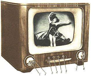
Analog television is the original television technology that uses analog signals to transmit video and audio. In an analog television broadcast, the brightness, colors and sound are represented by amplitude, phase and frequency of an analog signal.

The first American standard for analog television broadcast was developed by the National Television System Committee (NTSC) in 1941. In 1961, it was assigned the designation System M.

Phase Alternating Line (PAL) is a colour encoding system for analogue television. It was one of three major analogue colour television standards, the others being NTSC and SECAM. In most countries it was broadcast at 625 lines, 50 fields per second, and associated with CCIR analogue broadcast television systems B, D, G, H, I or K. The articles on analog broadcast television systems further describe frame rates, image resolution, and audio modulation.

Colorburst is an analog video, composite video signal generated by a video-signal generator used to keep the chrominance subcarrier synchronized in a color television signal. By synchronizing an oscillator with the colorburst at the back porch (beginning) of each scan line, a television receiver is able to restore the suppressed carrier of the chrominance (color) signals, and in turn decode the color information. The most common use of colorburst is to genlock equipment together as a common reference with a vision mixer in a television studio using a multi-camera setup.

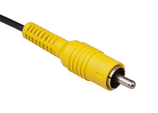
Composite video is an analog video format that typically carries a 525 or 625 line signal on a single channel, unlike the higher-quality S-Video and the even higher-quality component video.

ITU-R Recommendation BT.601, more commonly known by the abbreviations Rec. 601 or BT.601, is a standard originally issued in 1982 by the CCIR for encoding interlaced analog video signals in digital video form. It includes methods of encoding 525-line 60 Hz and 625-line 50 Hz signals, both with an active region covering 720 luminance samples and 360 chrominance samples per line. The color encoding system is known as YCbCr 4:2:2.

SMPTE color bars are a television test pattern used where the NTSC video standard is utilized, including countries in North America. The Society of Motion Picture and Television Engineers (SMPTE) refers to the pattern as Engineering Guideline (EG) 1-1990. Its components are a known standard, and created by test pattern generators. Comparing it as received to the known standard gives video engineers an indication of how an NTSC video signal has been altered by recording or transmission and what adjustments must be made to bring it back to specification. It is also used for setting a television monitor or receiver to reproduce NTSC chrominance and luminance information correctly.

576i is a standard-definition digital video mode, originally used for digitizing analogue television in most countries of the world where the utility frequency for electric power distribution is 50 Hz. Because of its close association with the legacy colour encoding systems, it is often referred to as PAL, PAL/SECAM or SECAM when compared to its 60 Hz NTSC-colour-encoded counterpart, 480i.
Overscan is a behaviour in certain television sets, in which part of the input picture is cut off by the visible bounds of the screen. It exists because cathode-ray tube (CRT) television sets from the 1930s to the early 2000s were highly variable in how the video image was positioned within the borders of the screen. It then became common practice to have video signals with black edges around the picture, which the television was meant to discard in this way.
Horizontal blanking interval refers to a part of the process of displaying images on a computer monitor or television screen via raster scanning. CRT screens display images by moving beams of electrons very quickly across the screen. Once the beam of the monitor has reached the edge of the screen, it is switched off, and the deflection circuit voltages are returned to the values they had for the other edge of the screen; this would have the effect of retracing the screen in the opposite direction, so the beam is turned off during this time. This part of the line display process is the Horizontal Blank.
Nominal analogue blanking is the outermost part of the overscan of a standard definition digital television image. It consists of a gap of black pixels at the left and right sides, which correspond to the end and start of the horizontal blanking interval: the front porch at the right side, and the back porch at the left side. Digital television ordinarily contains 720 pixels per line, but only 702 (PAL) to 704 (NTSC) of them contain picture content. The location is variable, since analogue equipment may shift the picture sideways in an unexpected amount or direction.
Broadcast-safe video is a term used in the broadcast industry to define video and audio compliant with the technical or regulatory broadcast requirements of the target area or region the feed might be broadcasting to. In the United States, the Federal Communications Commission (FCC) is the regulatory authority; in most of Europe, standards are set by the European Broadcasting Union (EBU).
A white clipper is a circuit in professional video products that limits the maximum amplitude of the luminance part of the analogue video signal to 1 volt. It is essential for both analogue recording and transmission of video material.
Differential gain is a kind of linearity distortion that affects the amplification and transmission of analog signals. It can visibly affect color saturation in analog TV broadcasting.
The following outline is provided as an overview of and topical guide to television broadcasting:
Differential phase is a kind of linearity distortion which affects the color hue in TV broadcasting.
The output power of a TV transmitter is the electric power applied to antenna system. There are two definitions: nominal and thermal. Analogue television systems put about 70% to 90% of the transmitters power into the sync pulses. The remainder of the transmitter's power goes into transmitting the video's higher frequencies and the FM audio carrier. Digital television modulation systems are about 30% more efficient than analogue modulation systems overall.
This glossary defines terms that are used in the document "Defining Video Quality Requirements: A Guide for Public Safety", developed by the Video Quality in Public Safety (VQIPS) Working Group. It contains terminology and explanations of concepts relevant to the video industry. The purpose of the glossary is to inform the reader of commonly used vocabulary terms in the video domain. This glossary was compiled from various industry sources.
In video technology, blanking level is the level of the composite video signal during the front and back porches of the video signal.

Black and burst, also known as bi-level sync and black burst, is an analogue signal used in broadcasting. It is a composite video signal with a black picture. It is a reference signal used to synchronise video equipment, in order to have them output video signals with the same timing. This allows seamless switching between two video signals.


