US9447489B2 - Methods of making photovoltaic devices and photovoltaic devices - Google Patents
Methods of making photovoltaic devices and photovoltaic devices Download PDFInfo
- Publication number
- US9447489B2 US9447489B2 US13/165,298 US201113165298A US9447489B2 US 9447489 B2 US9447489 B2 US 9447489B2 US 201113165298 A US201113165298 A US 201113165298A US 9447489 B2 US9447489 B2 US 9447489B2
- Authority
- US
- United States
- Prior art keywords
- region
- oxygen
- layer
- concentration
- absorber layer
- Prior art date
- Legal status (The legal status is an assumption and is not a legal conclusion. Google has not performed a legal analysis and makes no representation as to the accuracy of the status listed.)
- Expired - Fee Related, expires
Links
- 238000000034 method Methods 0.000 title abstract description 67
- 229910052760 oxygen Inorganic materials 0.000 claims abstract description 173
- QVGXLLKOCUKJST-UHFFFAOYSA-N atomic oxygen Chemical compound [O] QVGXLLKOCUKJST-UHFFFAOYSA-N 0.000 claims abstract description 172
- 239000001301 oxygen Substances 0.000 claims abstract description 172
- 239000006096 absorbing agent Substances 0.000 claims abstract description 114
- 238000004519 manufacturing process Methods 0.000 abstract description 8
- 238000000151 deposition Methods 0.000 description 76
- 230000008021 deposition Effects 0.000 description 67
- MARUHZGHZWCEQU-UHFFFAOYSA-N 5-phenyl-2h-tetrazole Chemical compound C1=CC=CC=C1C1=NNN=N1 MARUHZGHZWCEQU-UHFFFAOYSA-N 0.000 description 46
- 239000004065 semiconductor Substances 0.000 description 22
- YKYOUMDCQGMQQO-UHFFFAOYSA-L cadmium dichloride Chemical compound Cl[Cd]Cl YKYOUMDCQGMQQO-UHFFFAOYSA-L 0.000 description 21
- 239000000463 material Substances 0.000 description 21
- 230000007704 transition Effects 0.000 description 17
- WUPHOULIZUERAE-UHFFFAOYSA-N 3-(oxolan-2-yl)propanoic acid Chemical compound OC(=O)CCC1CCCO1 WUPHOULIZUERAE-UHFFFAOYSA-N 0.000 description 16
- 229910052980 cadmium sulfide Inorganic materials 0.000 description 16
- 239000000203 mixture Substances 0.000 description 12
- 229910052751 metal Inorganic materials 0.000 description 10
- 239000002184 metal Substances 0.000 description 10
- XOLBLPGZBRYERU-UHFFFAOYSA-N tin dioxide Chemical compound O=[Sn]=O XOLBLPGZBRYERU-UHFFFAOYSA-N 0.000 description 10
- XLOMVQKBTHCTTD-UHFFFAOYSA-N Zinc monoxide Chemical compound [Zn]=O XLOMVQKBTHCTTD-UHFFFAOYSA-N 0.000 description 8
- 238000002202 sandwich sublimation Methods 0.000 description 8
- 239000000758 substrate Substances 0.000 description 8
- 230000007423 decrease Effects 0.000 description 7
- 239000011261 inert gas Substances 0.000 description 7
- 230000000052 comparative effect Effects 0.000 description 6
- SKJCKYVIQGBWTN-UHFFFAOYSA-N (4-hydroxyphenyl) methanesulfonate Chemical compound CS(=O)(=O)OC1=CC=C(O)C=C1 SKJCKYVIQGBWTN-UHFFFAOYSA-N 0.000 description 5
- 239000010949 copper Substances 0.000 description 5
- 238000002360 preparation method Methods 0.000 description 5
- 230000008569 process Effects 0.000 description 5
- XKRFYHLGVUSROY-UHFFFAOYSA-N Argon Chemical compound [Ar] XKRFYHLGVUSROY-UHFFFAOYSA-N 0.000 description 4
- RYGMFSIKBFXOCR-UHFFFAOYSA-N Copper Chemical compound [Cu] RYGMFSIKBFXOCR-UHFFFAOYSA-N 0.000 description 4
- 229910052802 copper Inorganic materials 0.000 description 4
- 238000005530 etching Methods 0.000 description 4
- 230000005855 radiation Effects 0.000 description 4
- 239000011787 zinc oxide Substances 0.000 description 4
- 230000002411 adverse Effects 0.000 description 3
- 230000008859 change Effects 0.000 description 3
- 238000005137 deposition process Methods 0.000 description 3
- 239000002019 doping agent Substances 0.000 description 3
- 230000006870 function Effects 0.000 description 3
- PCHJSUWPFVWCPO-UHFFFAOYSA-N gold Chemical compound [Au] PCHJSUWPFVWCPO-UHFFFAOYSA-N 0.000 description 3
- 229910052737 gold Inorganic materials 0.000 description 3
- 239000010931 gold Substances 0.000 description 3
- PXHVJJICTQNCMI-UHFFFAOYSA-N nickel Substances [Ni] PXHVJJICTQNCMI-UHFFFAOYSA-N 0.000 description 3
- 238000000623 plasma-assisted chemical vapour deposition Methods 0.000 description 3
- 238000004544 sputter deposition Methods 0.000 description 3
- XSOKHXFFCGXDJZ-UHFFFAOYSA-N telluride(2-) Chemical compound [Te-2] XSOKHXFFCGXDJZ-UHFFFAOYSA-N 0.000 description 3
- 239000011701 zinc Substances 0.000 description 3
- PFNQVRZLDWYSCW-UHFFFAOYSA-N (fluoren-9-ylideneamino) n-naphthalen-1-ylcarbamate Chemical compound C12=CC=CC=C2C2=CC=CC=C2C1=NOC(=O)NC1=CC=CC2=CC=CC=C12 PFNQVRZLDWYSCW-UHFFFAOYSA-N 0.000 description 2
- IJGRMHOSHXDMSA-UHFFFAOYSA-N Atomic nitrogen Chemical compound N#N IJGRMHOSHXDMSA-UHFFFAOYSA-N 0.000 description 2
- KDLHZDBZIXYQEI-UHFFFAOYSA-N Palladium Chemical compound [Pd] KDLHZDBZIXYQEI-UHFFFAOYSA-N 0.000 description 2
- VYPSYNLAJGMNEJ-UHFFFAOYSA-N Silicium dioxide Chemical compound O=[Si]=O VYPSYNLAJGMNEJ-UHFFFAOYSA-N 0.000 description 2
- 229910000577 Silicon-germanium Inorganic materials 0.000 description 2
- BQCADISMDOOEFD-UHFFFAOYSA-N Silver Chemical compound [Ag] BQCADISMDOOEFD-UHFFFAOYSA-N 0.000 description 2
- 239000005083 Zinc sulfide Substances 0.000 description 2
- KTSFMFGEAAANTF-UHFFFAOYSA-N [Cu].[Se].[Se].[In] Chemical compound [Cu].[Se].[Se].[In] KTSFMFGEAAANTF-UHFFFAOYSA-N 0.000 description 2
- 239000011149 active material Substances 0.000 description 2
- 229910052782 aluminium Inorganic materials 0.000 description 2
- XAGFODPZIPBFFR-UHFFFAOYSA-N aluminium Chemical compound [Al] XAGFODPZIPBFFR-UHFFFAOYSA-N 0.000 description 2
- 229910052786 argon Inorganic materials 0.000 description 2
- 229910052785 arsenic Inorganic materials 0.000 description 2
- RQNWIZPPADIBDY-UHFFFAOYSA-N arsenic atom Chemical compound [As] RQNWIZPPADIBDY-UHFFFAOYSA-N 0.000 description 2
- 230000005540 biological transmission Effects 0.000 description 2
- CXKCTMHTOKXKQT-UHFFFAOYSA-N cadmium oxide Inorganic materials [Cd]=O CXKCTMHTOKXKQT-UHFFFAOYSA-N 0.000 description 2
- QWUZMTJBRUASOW-UHFFFAOYSA-N cadmium tellanylidenezinc Chemical compound [Zn].[Cd].[Te] QWUZMTJBRUASOW-UHFFFAOYSA-N 0.000 description 2
- CFEAAQFZALKQPA-UHFFFAOYSA-N cadmium(2+);oxygen(2-) Chemical compound [O-2].[Cd+2] CFEAAQFZALKQPA-UHFFFAOYSA-N 0.000 description 2
- 238000006243 chemical reaction Methods 0.000 description 2
- 238000004070 electrodeposition Methods 0.000 description 2
- 239000007789 gas Substances 0.000 description 2
- 229910052734 helium Inorganic materials 0.000 description 2
- 239000001307 helium Substances 0.000 description 2
- SWQJXJOGLNCZEY-UHFFFAOYSA-N helium atom Chemical compound [He] SWQJXJOGLNCZEY-UHFFFAOYSA-N 0.000 description 2
- 229910003437 indium oxide Inorganic materials 0.000 description 2
- PJXISJQVUVHSOJ-UHFFFAOYSA-N indium(iii) oxide Chemical compound [O-2].[O-2].[O-2].[In+3].[In+3] PJXISJQVUVHSOJ-UHFFFAOYSA-N 0.000 description 2
- 229910052759 nickel Inorganic materials 0.000 description 2
- KYKLWYKWCAYAJY-UHFFFAOYSA-N oxotin;zinc Chemical compound [Zn].[Sn]=O KYKLWYKWCAYAJY-UHFFFAOYSA-N 0.000 description 2
- BASFCYQUMIYNBI-UHFFFAOYSA-N platinum Chemical compound [Pt] BASFCYQUMIYNBI-UHFFFAOYSA-N 0.000 description 2
- 229910052709 silver Inorganic materials 0.000 description 2
- 239000004332 silver Substances 0.000 description 2
- 239000005361 soda-lime glass Substances 0.000 description 2
- 239000007787 solid Substances 0.000 description 2
- 230000003068 static effect Effects 0.000 description 2
- 239000010409 thin film Substances 0.000 description 2
- 229910001887 tin oxide Inorganic materials 0.000 description 2
- 229910052984 zinc sulfide Inorganic materials 0.000 description 2
- VYZAMTAEIAYCRO-UHFFFAOYSA-N Chromium Chemical compound [Cr] VYZAMTAEIAYCRO-UHFFFAOYSA-N 0.000 description 1
- 229910001218 Gallium arsenide Inorganic materials 0.000 description 1
- DGAQECJNVWCQMB-PUAWFVPOSA-M Ilexoside XXIX Chemical compound C[C@@H]1CC[C@@]2(CC[C@@]3(C(=CC[C@H]4[C@]3(CC[C@@H]5[C@@]4(CC[C@@H](C5(C)C)OS(=O)(=O)[O-])C)C)[C@@H]2[C@]1(C)O)C)C(=O)O[C@H]6[C@@H]([C@H]([C@@H]([C@H](O6)CO)O)O)O.[Na+] DGAQECJNVWCQMB-PUAWFVPOSA-M 0.000 description 1
- ZOKXTWBITQBERF-UHFFFAOYSA-N Molybdenum Chemical compound [Mo] ZOKXTWBITQBERF-UHFFFAOYSA-N 0.000 description 1
- OAICVXFJPJFONN-UHFFFAOYSA-N Phosphorus Chemical compound [P] OAICVXFJPJFONN-UHFFFAOYSA-N 0.000 description 1
- 239000004642 Polyimide Substances 0.000 description 1
- NINIDFKCEFEMDL-UHFFFAOYSA-N Sulfur Chemical compound [S] NINIDFKCEFEMDL-UHFFFAOYSA-N 0.000 description 1
- UCKMPCXJQFINFW-UHFFFAOYSA-N Sulphide Chemical compound [S-2] UCKMPCXJQFINFW-UHFFFAOYSA-N 0.000 description 1
- HCHKCACWOHOZIP-UHFFFAOYSA-N Zinc Chemical compound [Zn] HCHKCACWOHOZIP-UHFFFAOYSA-N 0.000 description 1
- QDOSJNSYIUHXQG-UHFFFAOYSA-N [Mn].[Cd] Chemical compound [Mn].[Cd] QDOSJNSYIUHXQG-UHFFFAOYSA-N 0.000 description 1
- 239000002253 acid Substances 0.000 description 1
- 238000005275 alloying Methods 0.000 description 1
- 229910021417 amorphous silicon Inorganic materials 0.000 description 1
- 238000000137 annealing Methods 0.000 description 1
- 230000003466 anti-cipated effect Effects 0.000 description 1
- 230000003667 anti-reflective effect Effects 0.000 description 1
- 229910052787 antimony Inorganic materials 0.000 description 1
- WATWJIUSRGPENY-UHFFFAOYSA-N antimony atom Chemical compound [Sb] WATWJIUSRGPENY-UHFFFAOYSA-N 0.000 description 1
- MRPWWVMHWSDJEH-UHFFFAOYSA-N antimony telluride Chemical compound [SbH3+3].[SbH3+3].[TeH2-2].[TeH2-2].[TeH2-2] MRPWWVMHWSDJEH-UHFFFAOYSA-N 0.000 description 1
- 230000004888 barrier function Effects 0.000 description 1
- 229910052797 bismuth Inorganic materials 0.000 description 1
- JCXGWMGPZLAOME-UHFFFAOYSA-N bismuth atom Chemical compound [Bi] JCXGWMGPZLAOME-UHFFFAOYSA-N 0.000 description 1
- 239000005388 borosilicate glass Substances 0.000 description 1
- 229910052793 cadmium Inorganic materials 0.000 description 1
- WZGKIRHYWDCEKP-UHFFFAOYSA-N cadmium magnesium Chemical compound [Mg].[Cd] WZGKIRHYWDCEKP-UHFFFAOYSA-N 0.000 description 1
- AQCDIIAORKRFCD-UHFFFAOYSA-N cadmium selenide Chemical compound [Cd]=[Se] AQCDIIAORKRFCD-UHFFFAOYSA-N 0.000 description 1
- CJOBVZJTOIVNNF-UHFFFAOYSA-N cadmium sulfide Chemical compound [Cd]=S CJOBVZJTOIVNNF-UHFFFAOYSA-N 0.000 description 1
- BEQNOZDXPONEMR-UHFFFAOYSA-N cadmium;oxotin Chemical compound [Cd].[Sn]=O BEQNOZDXPONEMR-UHFFFAOYSA-N 0.000 description 1
- 239000002800 charge carrier Substances 0.000 description 1
- 238000005229 chemical vapour deposition Methods 0.000 description 1
- 229910052804 chromium Inorganic materials 0.000 description 1
- 239000011651 chromium Substances 0.000 description 1
- 239000000470 constituent Substances 0.000 description 1
- WILFBXOGIULNAF-UHFFFAOYSA-N copper sulfanylidenetin zinc Chemical compound [Sn]=S.[Zn].[Cu] WILFBXOGIULNAF-UHFFFAOYSA-N 0.000 description 1
- LBJNMUFDOHXDFG-UHFFFAOYSA-N copper;hydrate Chemical compound O.[Cu].[Cu] LBJNMUFDOHXDFG-UHFFFAOYSA-N 0.000 description 1
- LCUOIYYHNRBAFS-UHFFFAOYSA-N copper;sulfanylideneindium Chemical compound [Cu].[In]=S LCUOIYYHNRBAFS-UHFFFAOYSA-N 0.000 description 1
- 229910021419 crystalline silicon Inorganic materials 0.000 description 1
- 238000009792 diffusion process Methods 0.000 description 1
- 238000003618 dip coating Methods 0.000 description 1
- 230000005670 electromagnetic radiation Effects 0.000 description 1
- 238000005516 engineering process Methods 0.000 description 1
- 230000008020 evaporation Effects 0.000 description 1
- 238000001704 evaporation Methods 0.000 description 1
- 230000005281 excited state Effects 0.000 description 1
- 230000005283 ground state Effects 0.000 description 1
- 238000010438 heat treatment Methods 0.000 description 1
- 229910052738 indium Inorganic materials 0.000 description 1
- APFVFJFRJDLVQX-UHFFFAOYSA-N indium atom Chemical compound [In] APFVFJFRJDLVQX-UHFFFAOYSA-N 0.000 description 1
- AMGQUBHHOARCQH-UHFFFAOYSA-N indium;oxotin Chemical compound [In].[Sn]=O AMGQUBHHOARCQH-UHFFFAOYSA-N 0.000 description 1
- 150000002500 ions Chemical class 0.000 description 1
- 238000001755 magnetron sputter deposition Methods 0.000 description 1
- VMINMXIEZOMBRH-UHFFFAOYSA-N manganese(ii) telluride Chemical compound [Te]=[Mn] VMINMXIEZOMBRH-UHFFFAOYSA-N 0.000 description 1
- VCEXCCILEWFFBG-UHFFFAOYSA-N mercury telluride Chemical compound [Hg]=[Te] VCEXCCILEWFFBG-UHFFFAOYSA-N 0.000 description 1
- 229910021424 microcrystalline silicon Inorganic materials 0.000 description 1
- 229910052750 molybdenum Inorganic materials 0.000 description 1
- 239000011733 molybdenum Substances 0.000 description 1
- 229910052757 nitrogen Inorganic materials 0.000 description 1
- 230000003287 optical effect Effects 0.000 description 1
- 229910052763 palladium Inorganic materials 0.000 description 1
- 230000035515 penetration Effects 0.000 description 1
- 229910052698 phosphorus Inorganic materials 0.000 description 1
- 239000011574 phosphorus Substances 0.000 description 1
- 238000005240 physical vapour deposition Methods 0.000 description 1
- 229910052697 platinum Inorganic materials 0.000 description 1
- 229920001721 polyimide Polymers 0.000 description 1
- 238000002310 reflectometry Methods 0.000 description 1
- 239000005368 silicate glass Substances 0.000 description 1
- 229910052708 sodium Inorganic materials 0.000 description 1
- 239000011734 sodium Substances 0.000 description 1
- 238000004528 spin coating Methods 0.000 description 1
- 238000005507 spraying Methods 0.000 description 1
- 229940071182 stannate Drugs 0.000 description 1
- 238000005092 sublimation method Methods 0.000 description 1
- 238000006467 substitution reaction Methods 0.000 description 1
- 229910052717 sulfur Inorganic materials 0.000 description 1
- 239000011593 sulfur Substances 0.000 description 1
- 229910052715 tantalum Inorganic materials 0.000 description 1
- GUVRBAGPIYLISA-UHFFFAOYSA-N tantalum atom Chemical compound [Ta] GUVRBAGPIYLISA-UHFFFAOYSA-N 0.000 description 1
- PUZSUGPVBHGJRE-UHFFFAOYSA-N tellanylideneberyllium Chemical compound [Te]=[Be] PUZSUGPVBHGJRE-UHFFFAOYSA-N 0.000 description 1
- ZTBJFXYWWZPTFM-UHFFFAOYSA-N tellanylidenemagnesium Chemical compound [Te]=[Mg] ZTBJFXYWWZPTFM-UHFFFAOYSA-N 0.000 description 1
- 229910052714 tellurium Inorganic materials 0.000 description 1
- WFKWXMTUELFFGS-UHFFFAOYSA-N tungsten Chemical compound [W] WFKWXMTUELFFGS-UHFFFAOYSA-N 0.000 description 1
- 229910052721 tungsten Inorganic materials 0.000 description 1
- 239000010937 tungsten Substances 0.000 description 1
- 229910052725 zinc Inorganic materials 0.000 description 1
- YVTHLONGBIQYBO-UHFFFAOYSA-N zinc indium(3+) oxygen(2-) Chemical compound [O--].[Zn++].[In+3] YVTHLONGBIQYBO-UHFFFAOYSA-N 0.000 description 1
- 229960001296 zinc oxide Drugs 0.000 description 1
- DRDVZXDWVBGGMH-UHFFFAOYSA-N zinc;sulfide Chemical compound [S-2].[Zn+2] DRDVZXDWVBGGMH-UHFFFAOYSA-N 0.000 description 1
Images


Classifications
-
- C—CHEMISTRY; METALLURGY
- C23—COATING METALLIC MATERIAL; COATING MATERIAL WITH METALLIC MATERIAL; CHEMICAL SURFACE TREATMENT; DIFFUSION TREATMENT OF METALLIC MATERIAL; COATING BY VACUUM EVAPORATION, BY SPUTTERING, BY ION IMPLANTATION OR BY CHEMICAL VAPOUR DEPOSITION, IN GENERAL; INHIBITING CORROSION OF METALLIC MATERIAL OR INCRUSTATION IN GENERAL
- C23C—COATING METALLIC MATERIAL; COATING MATERIAL WITH METALLIC MATERIAL; SURFACE TREATMENT OF METALLIC MATERIAL BY DIFFUSION INTO THE SURFACE, BY CHEMICAL CONVERSION OR SUBSTITUTION; COATING BY VACUUM EVAPORATION, BY SPUTTERING, BY ION IMPLANTATION OR BY CHEMICAL VAPOUR DEPOSITION, IN GENERAL
- C23C14/00—Coating by vacuum evaporation, by sputtering or by ion implantation of the coating forming material
- C23C14/06—Coating by vacuum evaporation, by sputtering or by ion implantation of the coating forming material characterised by the coating material
- C23C14/0623—Sulfides, selenides or tellurides
- C23C14/0629—Sulfides, selenides or tellurides of zinc, cadmium or mercury
-
- C—CHEMISTRY; METALLURGY
- C23—COATING METALLIC MATERIAL; COATING MATERIAL WITH METALLIC MATERIAL; CHEMICAL SURFACE TREATMENT; DIFFUSION TREATMENT OF METALLIC MATERIAL; COATING BY VACUUM EVAPORATION, BY SPUTTERING, BY ION IMPLANTATION OR BY CHEMICAL VAPOUR DEPOSITION, IN GENERAL; INHIBITING CORROSION OF METALLIC MATERIAL OR INCRUSTATION IN GENERAL
- C23C—COATING METALLIC MATERIAL; COATING MATERIAL WITH METALLIC MATERIAL; SURFACE TREATMENT OF METALLIC MATERIAL BY DIFFUSION INTO THE SURFACE, BY CHEMICAL CONVERSION OR SUBSTITUTION; COATING BY VACUUM EVAPORATION, BY SPUTTERING, BY ION IMPLANTATION OR BY CHEMICAL VAPOUR DEPOSITION, IN GENERAL
- C23C14/00—Coating by vacuum evaporation, by sputtering or by ion implantation of the coating forming material
- C23C14/22—Coating by vacuum evaporation, by sputtering or by ion implantation of the coating forming material characterised by the process of coating
- C23C14/54—Controlling or regulating the coating process
- C23C14/548—Controlling the composition
-
- C—CHEMISTRY; METALLURGY
- C23—COATING METALLIC MATERIAL; COATING MATERIAL WITH METALLIC MATERIAL; CHEMICAL SURFACE TREATMENT; DIFFUSION TREATMENT OF METALLIC MATERIAL; COATING BY VACUUM EVAPORATION, BY SPUTTERING, BY ION IMPLANTATION OR BY CHEMICAL VAPOUR DEPOSITION, IN GENERAL; INHIBITING CORROSION OF METALLIC MATERIAL OR INCRUSTATION IN GENERAL
- C23C—COATING METALLIC MATERIAL; COATING MATERIAL WITH METALLIC MATERIAL; SURFACE TREATMENT OF METALLIC MATERIAL BY DIFFUSION INTO THE SURFACE, BY CHEMICAL CONVERSION OR SUBSTITUTION; COATING BY VACUUM EVAPORATION, BY SPUTTERING, BY ION IMPLANTATION OR BY CHEMICAL VAPOUR DEPOSITION, IN GENERAL
- C23C18/00—Chemical coating by decomposition of either liquid compounds or solutions of the coating forming compounds, without leaving reaction products of surface material in the coating; Contact plating
- C23C18/02—Chemical coating by decomposition of either liquid compounds or solutions of the coating forming compounds, without leaving reaction products of surface material in the coating; Contact plating by thermal decomposition
- C23C18/12—Chemical coating by decomposition of either liquid compounds or solutions of the coating forming compounds, without leaving reaction products of surface material in the coating; Contact plating by thermal decomposition characterised by the deposition of inorganic material other than metallic material
- C23C18/1204—Chemical coating by decomposition of either liquid compounds or solutions of the coating forming compounds, without leaving reaction products of surface material in the coating; Contact plating by thermal decomposition characterised by the deposition of inorganic material other than metallic material inorganic material, e.g. non-oxide and non-metallic such as sulfides, nitrides based compounds
-
- C—CHEMISTRY; METALLURGY
- C23—COATING METALLIC MATERIAL; COATING MATERIAL WITH METALLIC MATERIAL; CHEMICAL SURFACE TREATMENT; DIFFUSION TREATMENT OF METALLIC MATERIAL; COATING BY VACUUM EVAPORATION, BY SPUTTERING, BY ION IMPLANTATION OR BY CHEMICAL VAPOUR DEPOSITION, IN GENERAL; INHIBITING CORROSION OF METALLIC MATERIAL OR INCRUSTATION IN GENERAL
- C23C—COATING METALLIC MATERIAL; COATING MATERIAL WITH METALLIC MATERIAL; SURFACE TREATMENT OF METALLIC MATERIAL BY DIFFUSION INTO THE SURFACE, BY CHEMICAL CONVERSION OR SUBSTITUTION; COATING BY VACUUM EVAPORATION, BY SPUTTERING, BY ION IMPLANTATION OR BY CHEMICAL VAPOUR DEPOSITION, IN GENERAL
- C23C18/00—Chemical coating by decomposition of either liquid compounds or solutions of the coating forming compounds, without leaving reaction products of surface material in the coating; Contact plating
- C23C18/02—Chemical coating by decomposition of either liquid compounds or solutions of the coating forming compounds, without leaving reaction products of surface material in the coating; Contact plating by thermal decomposition
- C23C18/12—Chemical coating by decomposition of either liquid compounds or solutions of the coating forming compounds, without leaving reaction products of surface material in the coating; Contact plating by thermal decomposition characterised by the deposition of inorganic material other than metallic material
- C23C18/125—Process of deposition of the inorganic material
- C23C18/1279—Process of deposition of the inorganic material performed under reactive atmosphere, e.g. oxidising or reducing atmospheres
-
- C—CHEMISTRY; METALLURGY
- C23—COATING METALLIC MATERIAL; COATING MATERIAL WITH METALLIC MATERIAL; CHEMICAL SURFACE TREATMENT; DIFFUSION TREATMENT OF METALLIC MATERIAL; COATING BY VACUUM EVAPORATION, BY SPUTTERING, BY ION IMPLANTATION OR BY CHEMICAL VAPOUR DEPOSITION, IN GENERAL; INHIBITING CORROSION OF METALLIC MATERIAL OR INCRUSTATION IN GENERAL
- C23C—COATING METALLIC MATERIAL; COATING MATERIAL WITH METALLIC MATERIAL; SURFACE TREATMENT OF METALLIC MATERIAL BY DIFFUSION INTO THE SURFACE, BY CHEMICAL CONVERSION OR SUBSTITUTION; COATING BY VACUUM EVAPORATION, BY SPUTTERING, BY ION IMPLANTATION OR BY CHEMICAL VAPOUR DEPOSITION, IN GENERAL
- C23C18/00—Chemical coating by decomposition of either liquid compounds or solutions of the coating forming compounds, without leaving reaction products of surface material in the coating; Contact plating
- C23C18/02—Chemical coating by decomposition of either liquid compounds or solutions of the coating forming compounds, without leaving reaction products of surface material in the coating; Contact plating by thermal decomposition
- C23C18/12—Chemical coating by decomposition of either liquid compounds or solutions of the coating forming compounds, without leaving reaction products of surface material in the coating; Contact plating by thermal decomposition characterised by the deposition of inorganic material other than metallic material
- C23C18/125—Process of deposition of the inorganic material
- C23C18/1291—Process of deposition of the inorganic material by heating of the substrate
-
- H01L31/0296—
-
- H01L31/073—
-
- H01L31/0749—
-
- H01L31/1828—
-
- H01L31/1832—
-
- Y—GENERAL TAGGING OF NEW TECHNOLOGICAL DEVELOPMENTS; GENERAL TAGGING OF CROSS-SECTIONAL TECHNOLOGIES SPANNING OVER SEVERAL SECTIONS OF THE IPC; TECHNICAL SUBJECTS COVERED BY FORMER USPC CROSS-REFERENCE ART COLLECTIONS [XRACs] AND DIGESTS
- Y02—TECHNOLOGIES OR APPLICATIONS FOR MITIGATION OR ADAPTATION AGAINST CLIMATE CHANGE
- Y02E—REDUCTION OF GREENHOUSE GAS [GHG] EMISSIONS, RELATED TO ENERGY GENERATION, TRANSMISSION OR DISTRIBUTION
- Y02E10/00—Energy generation through renewable energy sources
- Y02E10/50—Photovoltaic [PV] energy
- Y02E10/541—CuInSe2 material PV cells
-
- Y—GENERAL TAGGING OF NEW TECHNOLOGICAL DEVELOPMENTS; GENERAL TAGGING OF CROSS-SECTIONAL TECHNOLOGIES SPANNING OVER SEVERAL SECTIONS OF THE IPC; TECHNICAL SUBJECTS COVERED BY FORMER USPC CROSS-REFERENCE ART COLLECTIONS [XRACs] AND DIGESTS
- Y02—TECHNOLOGIES OR APPLICATIONS FOR MITIGATION OR ADAPTATION AGAINST CLIMATE CHANGE
- Y02E—REDUCTION OF GREENHOUSE GAS [GHG] EMISSIONS, RELATED TO ENERGY GENERATION, TRANSMISSION OR DISTRIBUTION
- Y02E10/00—Energy generation through renewable energy sources
- Y02E10/50—Photovoltaic [PV] energy
- Y02E10/543—Solar cells from Group II-VI materials
-
- Y—GENERAL TAGGING OF NEW TECHNOLOGICAL DEVELOPMENTS; GENERAL TAGGING OF CROSS-SECTIONAL TECHNOLOGIES SPANNING OVER SEVERAL SECTIONS OF THE IPC; TECHNICAL SUBJECTS COVERED BY FORMER USPC CROSS-REFERENCE ART COLLECTIONS [XRACs] AND DIGESTS
- Y02—TECHNOLOGIES OR APPLICATIONS FOR MITIGATION OR ADAPTATION AGAINST CLIMATE CHANGE
- Y02P—CLIMATE CHANGE MITIGATION TECHNOLOGIES IN THE PRODUCTION OR PROCESSING OF GOODS
- Y02P70/00—Climate change mitigation technologies in the production process for final industrial or consumer products
- Y02P70/50—Manufacturing or production processes characterised by the final manufactured product
-
- Y02P70/521—
Definitions
- the invention generally relates to photovoltaic devices and methods of making photovoltaic devices. More particularly, the invention relates to photovoltaic devices that include an absorber layer and methods of making photovoltaic devices that include an absorber layer.
- Thin film solar cells or photovoltaic devices typically include a plurality of semiconductor layers disposed on a transparent substrate, wherein one layer serves as a window layer and a second layer serves as an absorber layer.
- the window layer allows the penetration of solar radiation to the absorber layer, where the optical energy is converted to usable electrical energy.
- Cadmium telluride/cadmium sulfide (CdTe/CdS) heterojunction-based photovoltaic cells are one such example of thin film solar cells.
- Cadmium telluride (CdTe)-based photovoltaic devices typically demonstrate relatively low power conversion efficiencies, which may be attributed to a relatively low open circuit voltage (V oc ) in relation to the band gap of the material, which is due, in part, to the low effective carrier concentration and short minority carrier lifetime in CdTe.
- V oc open circuit voltage
- Improving minority carrier lifetimes in the absorber material may be desirable. Further, improved methods of depositing the CdTe layer on the CdS layer resulting in improved performance may be desirable.
- One embodiment is a method of making a photovoltaic device.
- the method includes disposing an absorber layer on a window layer, wherein the absorber layer includes a first region and a second region.
- the method includes disposing the first region adjacent to the window layer in a first environment including oxygen at a first partial pressure and disposing the second region on the first region in a second environment including oxygen at a second partial pressure, wherein the first partial pressure is greater than the second partial pressure.
- One embodiment is a method of making a photovoltaic device.
- the method includes disposing an absorber layer on a window layer, wherein the absorber layer includes a first region and a second region.
- the method includes disposing the first region adjacent to the window layer in a first environment including oxygen and controlling a partial pressure of oxygen in the first environment at a first partial pressure.
- the method further includes changing the partial pressure of oxygen in the first environment to a second partial pressure to form a second environment and disposing the second region on the first region in the second environment, wherein the first partial pressure is greater than the second partial pressure.
- the photovoltaic device includes a window layer and an absorber layer disposed on the window layer.
- the absorber layer includes a first region disposed adjacent to the window layer, the first region including oxygen at a first concentration, and a second region disposed on the first region, the second region including oxygen at a second concentration.
- a ratio of the first concentration to the second concentration is greater than about 10.
- FIG. 1 is a schematic of a chamber for deposition of an absorber layer, according to one embodiment of the invention.
- FIG. 2 is a schematic of a chamber for deposition of an absorber layer, according to one embodiment of the invention.
- FIG. 3 is a schematic of a chamber for deposition of an absorber layer, according to one embodiment of the invention.
- FIG. 4 is a schematic of a chamber for deposition of an absorber layer, according to one embodiment of the invention.
- FIG. 5 is a schematic of a photovoltaic device, according to one embodiment of the invention.
- FIG. 6 is a schematic of a photovoltaic device, according to one embodiment of the invention.
- FIG. 7 is a schematic of an absorber layer, according to one embodiment of the invention.
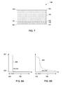
- FIG. 8A is an illustration of concentration profile of oxygen in the absorber layer, according to an exemplary embodiment of the invention.
- FIG. 8B is an illustration of concentration profile of oxygen in the absorber layer, according to an exemplary embodiment of the invention.
- FIG. 9 is a schematic of a chamber for deposition of an absorber layer, according to one embodiment of the invention.
- CdTe deposition on CdS in the presence of oxygen may be desirable as oxygen at the CdTe/CdS interface may provide improved interface characteristics (smaller grain sizes and lower pinhole density) that may result in higher device efficiencies and enhanced device stability.
- typical methods used to deposit CdTe in the presence of oxygen throughout the growth process may adversely affect CdTe material utilization and throughput as deposition rates are typically significantly lower in the presence of oxygen.
- some of the embodiments of the invention include methods of making photovoltaic devices including an absorber layer disposed in the presence of oxygen. Further, some of the embodiments of the invention include methods of making photovoltaic devices including disposing an absorber layer on a window layer in a step-wise manner, wherein the absorber layer includes a first region and a second region. In one embodiment, the method includes disposing the first region adjacent to the window layer in a first environment including oxygen at a first partial pressure such that the first region (at the interface between the window and absorber layers) includes oxygen.
- oxygen at the interface between the window and absorber layers provides improved interface properties (for example, smaller grain sizes, lower pinhole density, or enhanced alloying among layer constituent elements), allowing for high minority carrier lifetimes at the interface in contact with the window layer.
- the method further includes disposing a second region on the first region in a second environment including oxygen at a second partial pressure, such that a partial pressure of oxygen in the first environment is greater than a partial pressure of oxygen in the second environment.
- the second environment is substantially free of oxygen and the second region of the absorber layer is substantially free of oxygen.
- Approximating language may be applied to modify any quantitative representation that could permissibly vary without resulting in a change in the basic function to which it is related. Accordingly, a value modified by a term or terms, such as “about”, is not limited to the precise value specified. In some instances, the approximating language may correspond to the precision of an instrument for measuring the value.
- transparent region and “transparent layer” as used herein, refer to a region or a layer that allows an average transmission of at least 80% of incident electromagnetic radiation having a wavelength in a range from about 300 nm to about 850 nm.
- disposed on refers to layers disposed directly in contact with each other or indirectly by having intervening layers therebetween, unless otherwise specifically indicated.
- disosing on refers to a step of disposing layers directly in contact with each other or indirectly by having intervening layers therebetween, unless otherwise specifically indicated.
- One embodiment includes a method of making a photovoltaic device. The method is described with reference to FIGS. 1-6 . As indicated, for example, in FIGS. 1-6 the method includes disposing an absorber layer 160 on a window layer 130 , wherein the absorber layer 160 includes a first region 140 and a second region 150 . In one embodiment, as indicated in FIG. 1 , the method includes disposing the first region 140 adjacent to the window layer 130 in a first environment 201 including oxygen at a first partial pressure.
- the method further includes disposing the second region 150 on the first region 140 in a second environment 202 including oxygen at a second partial pressure, wherein the first partial pressure is greater than the second partial pressure.
- adjacent as used in this context means that the first region 140 is in direct contact with the window layer 130 .
- partial pressure refers to the pressure that a gas (for example, oxygen) in a mixture of gases would exert if it alone occupied the whole volume occupied by the mixture.
- the term partial pressure refers to the pressure exerted by oxygen in the first environment 201 .
- window layer refers to a semiconducting layer that is substantially transparent and forms a heterojunction with the absorber layer 160 .
- the window layer 130 includes an n-type semiconductor material.
- the absorber layer 160 may be doped to be p-type and the window layer 130 and the absorber layer 160 may form an “n-p” heterojunction.
- Non-limiting exemplary materials for the window layer 130 include cadmium sulfide (CdS), indium III sulfide (In 2 S 3 ), zinc sulfide (ZnS), zinc telluride (ZnTe), zinc selenide (ZnSe), cadmium selenide (CdSe), oxygenated cadmium sulfide (CdS:O), copper oxide (Cu 2 O), zinc oxihydrate (ZnO,H), or combinations thereof.
- the window layer 130 includes CdS.
- absorber layer refers to a semiconducting layer wherein the solar radiation is absorbed.
- solar radiation 10 is incident on the photovoltaic device 100 , electrons in the absorber layer 160 are excited from a lower energy “ground state,” in which they are bound to specific atoms in the solid, to a higher “excited state,” in which they can move through the solid.
- the absorber layer 160 includes a p-type semiconductor material.
- the absorber layer 160 has an effective carrier density in a range from about 1 ⁇ 10 13 per cubic centimeter to about 1 ⁇ 10 16 per cubic centimeter.
- the term “effective carrier density” refers to the average concentration of holes and/or electrons, as appropriate, in a material.
- the window layer 130 may be doped to be n-type, and the absorber layer 160 and the window layer 130 may form a “p-n” or “n-p” junction, as mentioned above.
- a photoactive material is used for forming the absorber layer 160 .
- Suitable photo-active materials include cadmium telluride (CdTe), cadmium zinc telluride (CdZnTe), cadmium magnesium telluride (CdMgTe), cadmium manganese telluride (CdMnTe), cadmium sulfur telluride (CdSTe), zinc telluride (ZnTe), copper indium sulphide (CIS), copper indium gallium selenide (CIGS), copper zinc tin sulphide (CZTS), or combinations thereof.
- the above-mentioned photo-active semiconductor materials may be used alone or in combination.
- the absorber layer 160 includes cadmium telluride (CdTe). In one particular embodiment, the absorber layer 160 includes p-type cadmium telluride (CdTe).
- the window layer 130 and the absorber layer 160 may be doped with a p-type dopant or an n-type dopant to form a heterojunction.
- a heterojunction is a semiconductor junction that is composed of layers of dissimilar semiconductor material. These materials usually have non-equal band gaps.
- a heterojunction can be formed by contact between a layer or region of one conductivity type with a layer or region of opposite conductivity, e.g., a “p-n” junction.
- the absorber layer 160 includes a first region 140 and a second region 150 .
- the first region 140 may function as an interfacial region between the window layer 130 and the second region 150 .
- the composition of the first region 140 may provide for desirable interface properties between the window layer 130 and the absorber layer 160 .
- the second region 150 of the absorber layer 160 may function as a bulk region of the absorber layer 160 .
- first region and interfacial region are used interchangeably.
- bulk region and “second region” are used herein interchangeably.
- the first region 140 has a thickness less than a thickness of the second region 150 .
- the first region 140 has a thickness in a range from about 100 nanometers to about 1500 nanometers.
- the first region 140 has a thickness in a range from about 100 nanometers to about 1000 nanometers.
- the first region 140 has a thickness in a range from about 100 nanometers to about 500 nanometers.
- the second region 150 has a thickness in a range from about 500 nanometers to about 3000 nanometers. In some embodiments, the second region 150 has a thickness in a range from about 750 nanometers to about 3000 nanometers. In particular embodiments, the second region 150 has a thickness in a range from about 1000 nanometers to about 3000 nanometers. In some embodiments, the absorber layer 160 has a thickness in a range from about 1000 nanometers to about 3000 nanometers. In particular embodiments, the absorber layer 160 has a thickness in a range from about 1000 nanometers to about 2000 nanometers.
- the absorber layer 160 may be deposited by close-space sublimation (CSS), vapor transport method (VTM), ion-assisted physical vapor deposition (IAPVD), radio frequency or pulsed magnetron sputtering (RFS or PMS), plasma enhanced chemical vapor deposition (PECVD), or electrochemical deposition (ECD).
- the absorber layer 160 may be deposited by close-space sublimation (CSS), diffused transport deposition (DTD), or vapor transport deposition (VTD).
- both the first region 140 and the second 150 of the absorber layer 160 may be deposited using the same deposition process. In some embodiments, both the first region 140 and the second region 150 of the absorber layer 160 are deposited by close-space sublimation (CSS), diffused transport deposition (DTD), or vapor transport deposition (VTD). In particular embodiments, both the first region 140 and the second 150 region of the absorber layer 160 are deposited by diffused transport deposition.
- CCS close-space sublimation
- DTD diffused transport deposition
- VTD vapor transport deposition
- both the first region 140 and the second 150 region of the absorber layer 160 are deposited by diffused transport deposition.
- the method includes disposing the absorber layer 160 in a step-wise manner, wherein disposing the absorber layer 160 includes disposing the first region 140 adjacent to the window layer 130 in a first environment 201 and disposing a second region 150 on the first region 140 in a second environment 202 .
- the method includes disposing the absorber layer 160 in a continuous manufacturing process.
- the method includes disposing the first region 140 adjacent to the window layer 130 in a first deposition chamber 210 .
- the method includes transferring the window layer 130 to the first deposition chamber 210 prior to the step of deposition of absorber layer 160 on the window layer 130 .
- the window layer 130 is further disposed on a transparent layer 120 , which is further disposed on a support 110 , as described later.
- the first deposition chamber 210 further includes at least one source 260 for the absorber layer 160 .
- the first deposition chamber 210 further includes at least one source 260 for cadmium telluride.
- the first region 140 is deposited in a first environment 201 present in the first deposition chamber 210 .
- the first environment 201 includes oxygen and the first region 140 is deposited adjacent to the window layer 130 in the presence of oxygen.
- the first deposition chamber 210 further includes at least one vent 212 for providing oxygen to the deposition chamber 210 , as indicated in FIG. 1 .
- the step of disposing the first region 140 adjacent to the window layer 130 includes controlling a partial pressure of oxygen in the first environment 201 at a first partial pressure. In some embodiments, controlling a partial pressure of oxygen in the first environment 201 at the first partial pressure includes continuously providing oxygen to the first environment 201 such that the desired partial pressure is maintained. In some embodiments, the method of disposing the absorber layer 160 includes disposing the first region 140 adjacent to the window layer 130 in the presence of a continuous flow of oxygen. In some embodiments, the first deposition chamber 210 includes a continuous flow of oxygen through the first deposition chamber, for example, via vents 212 and 213 , as indicated in FIG. 1 . This is in contrast to deposition process where the absorber layer 160 is deposited in a deposition chamber that includes a static supply of oxygen such that the oxygen content in the deposition chamber is not controlled.
- the first environment 201 further includes an inert gas.
- the method includes continuously flowing a mixture of oxygen and inert gas through the first deposition chamber 210 to maintain the first environment 201 .
- the first deposition chamber 210 includes a mixture of oxygen and inert gas present in an amount sufficient to maintain the desired chamber pressure for deposition of the first region 140 .
- the first environment 201 includes a mixture of oxygen and argon.
- the first environment 201 includes a mixture of oxygen and helium.
- the partial pressure of oxygen in the first environment 201 is maintained at a determined amount depending on one or more of the concentration of oxygen desired in the first region 140 , the thickness of the first region 140 , or the thickness of the absorber layer 160 .
- the partial pressure of oxygen in the first environment 201 is substantially constant over the time period for deposition of the first region 140 on the window layer 130 .
- the term “substantially constant” as used in this context means that the variation in the partial pressure of oxygen in the first environment 201 is less than about 10 percent over the deposition period for the first region 140 . This is in contrast to deposition process where the absorber layer 160 is deposited in a deposition chamber that includes a static supply of oxygen such that the oxygen content in the deposition chamber reduces over the period of deposition.
- the partial pressure of oxygen in the first environment 201 is in a range greater than about 0.1 Torr. In some embodiments, the partial pressure of oxygen in the first environment 201 is in a range greater than about 0.5 Torr. In some embodiments, the partial pressure of oxygen in the first environment 201 is in a range greater than about 1 Torr. In some embodiments, the partial pressure of oxygen in the first environment 201 is in a range from about 0.1 Torr to about 10 Torr. In particular embodiments, the partial pressure of oxygen in the first environment 201 is in a range from about 0.1 Torr to about 1 Torr.
- the partial pressure of oxygen in the first environment 201 is controlled such that a concentration of oxygen in the first region 140 is in a range from about 1 ⁇ 10 17 cm ⁇ 3 to about 1 ⁇ 10 21 cm ⁇ 3 . In some embodiments, the concentration of oxygen in the first region 140 is in a range from about 5 ⁇ 10 17 cm ⁇ 3 to about 5 ⁇ 10 20 cm ⁇ 3 . In particular embodiments, the concentration of oxygen in the first region 140 is in a range from about 1 ⁇ 10 18 cm ⁇ 3 to about 1 ⁇ 10 20 cm ⁇ 3 .
- concentration refers to the atomic concentration or the average number of atoms per unit volume of the oxygen present in the first region 140 or the second region 150 .
- concentration in the first region 140 or the second region 150 refers to the average concentration across the thickness of the first region 140 or the second region 150 .
- concentration of oxygen as described herein refers to the oxygen concentration in as-deposited first region 140 or second region 150 of the absorber layer 160 , that is, the concentration prior to any subsequent post-deposition treatment, for example, cadmium chloride treatment.
- the method includes disposing the first region 140 on the window layer 130 in a graded manner, such that the concentration of the oxygen is compositionally graded across the thickness of the first region 140 .
- the method includes disposing the first region 140 on the window layer 130 , such that the concentration of the oxygen is substantially constant across the thickness of the first region 140 .
- substantially constant as used in this context means that that the variation in the concentration of oxygen in the first region 140 is less than about 10 percent across the thickness of the first region 140 .
- compositionally graded as used in this context means that a concentration of oxygen continuously changes across a thickness of the first region 140 .
- the second region 150 is further disposed on the first region 140 in a second environment 202 , as indicated in FIG. 2 .
- the second region 150 is disposed in the first deposition chamber 210 and the step of disposing the second region 150 includes changing the partial pressure of oxygen in the first environment 201 to a second partial pressure.
- the method includes changing the partial pressure of oxygen in the first deposition chamber 210 to a second partial pressure to create a second environment 202 before or during the step of disposing the second region 150 .
- the concentration of oxygen flowing through the first deposition chamber is reduced such that a lower amount of oxygen is incorporated in the second region 150 as compared to the first region 140 .
- the partial pressure of oxygen in the second environment 202 is maintained at a determined amount depending on one or more of the concentration of oxygen desired in the second region 150 , the thickness of the second region 150 , or the thickness of the absorber layer 160 .
- the partial pressure of oxygen in the second environment 202 is substantially constant over the time period for deposition of the second region 150 on the window layer 130 .
- the term “substantially constant” as used in this context means that the variation in the partial pressure of oxygen in the second environment 202 is less than about 10 percent over the deposition period for the first region 150 .
- the partial pressure of oxygen in the second environment 202 continuously decreases over the deposition period of the second region 150 .
- the partial pressure of oxygen in the second environment 202 may be continuously varied by continuously reducing the flow of oxygen through the first deposition chamber 210 .
- the partial pressure of oxygen in the second environment 202 is controlled to obtain a determined concentration of oxygen in the second region 150 .
- the partial pressure of oxygen in the second environment 202 is in a range less than about 0.1 Torr. In some embodiments, the partial pressure of oxygen in the second environment 202 is in a range less than about 0.05 Torr. In some embodiments, the partial pressure of oxygen in the second environment 202 is in a range less than about 0.01 Torr.
- the second environment 202 further includes an inert gas.
- the method includes continuously flowing a mixture of oxygen and inert gas through the first deposition chamber 210 to maintain the second environment 202 .
- the first deposition chamber 210 includes a mixture of oxygen and inert gas present in an amount sufficient to maintain the desired chamber pressure for deposition of the second region 150 .
- the second environment 202 includes a mixture of oxygen and argon.
- the second environment 202 includes a mixture of oxygen and helium.
- the second environment 202 is substantially free of oxygen.
- the second environment includes an inert gas and the second region is deposited on the first region in the absence of oxygen.
- the method includes disposing a second region 150 on the first region 140 such that the second region 150 is substantially free of oxygen after the step of absorber layer deposition.
- substantially free as used in this context means that the concentration of oxygen in the second region 150 after the step of absorber layer deposition is less than about 1 ⁇ 10 18 cm ⁇ 3 . In some embodiments, the concentration of oxygen in the second region 150 after the step of absorber layer deposition is less than about 1 ⁇ 10 16 cm ⁇ 3 . In some embodiments, the concentration of oxygen in the second region 150 after the step of absorber layer deposition is less than about 1 ⁇ 10 15 cm ⁇ 3 .
- the concentration of oxygen in the second region 150 is for an as-deposited absorber layer 160 , that is, concentration in the absence of post-deposition processing.
- the method further includes treating the deposited absorber layer with cadmium chloride (CdCl 2 ).
- CdCl 2 cadmium chloride
- the concentration of oxygen in the absorber layer treated with CdCl 2 may be five times greater than the as-deposited absorber layer 160 .
- the concentration of oxygen in the absorber layer treated with CdCl 2 may be greater than the as-deposited absorber layer by at least an order of magnitude, that is, ten times greater.
- the method includes turning off the flow of oxygen to the first environment 201 of the deposition chamber 210 prior to the step of disposing the second region 150 .
- the second region 150 is disposed in a second environment 202 that is substantially free of oxygen.
- the method includes forming a partial absorber layer 190 after the step of disposing the first region 140 adjacent to the window layer 130 , as indicated in FIG. 1 .
- the method further includes transferring the partial absorber layer 190 to a second deposition chamber that is different from the first deposition chamber (not shown).
- the second deposition chamber includes a second environment 202 including oxygen at the second partial pressure.
- the method further includes disposing the second region 150 on the first region 140 in the second environment 202 of the second deposition chamber.
- the method includes continuously depositing the absorber layer 160 in a deposition chamber such that the oxygen is injected from one side, wherein the oxygen partial pressure is higher at the entry level of the window layer 130 and lower at the exit level of the window layer 130 .
- Some embodiments include a method of making a photovoltaic device.
- the method includes disposing an absorber layer 160 on a window layer 130 , as indicated in FIGS. 1-2 .
- the absorber layer 160 includes a first region 140 and a second region 150 .
- the method includes disposing the first region 140 adjacent to the window layer 130 in a first environment 201 including oxygen, as indicated in FIG. 1 .
- the method includes controlling a partial pressure of oxygen in the first environment 201 at a first partial pressure.
- the method further includes changing the partial pressure of oxygen in the first environment 201 to a second partial pressure to form a second environment 202 and disposing the second region 150 on the first region 140 in the second environment 202 , as indicated in FIG. 2 .
- the first partial pressure is greater than the second partial pressure.
- the second environment is substantially free of oxygen.
- changing the partial pressure of oxygen in the first environment 201 includes stopping the flow of oxygen.
- the method of the present invention advantageously allows for creation of a controlled concentration of oxygen at the interface between the window and absorber layers. Further, in some embodiments, the method advantageously allows for deposition of an absorber layer 160 , wherein the bulk of the absorber layer 150 is substantially free of oxygen. As noted earlier, oxygen in the bulk of the absorber layer may adversely affect the properties of the absorber layer (for example, CdTe) 160 .
- the method further includes interposing a transition region 145 between the first region 140 and the second region 150 in a third environment 203 , wherein the third environment includes oxygen at a third partial pressure, as indicated in FIG. 9 .
- the third partial pressure is lower than the first partial pressure and greater than the second partial pressure.
- the method includes reducing a flow of oxygen to the deposition chamber 210 to a third partial pressure, after the step of disposing the first region 140 .
- the partial pressure of oxygen in the third environment 203 is substantially constant over the time period for deposition of the transition region 145 on the first region 140 . In some other embodiments, the partial pressure of oxygen in the third environment 203 continuously decreases over the deposition period of the transition region 145 . In some embodiments, the partial pressure of oxygen in the third environment 203 may be continuously varied by continuously reducing the flow of oxygen through the first deposition chamber 210 .
- the partial pressure of oxygen in the third environment is controlled such that a transition region 145 with the desired oxygen concentration profile is interposed between the first region 140 and the second region 150 .
- the concentration of oxygen in the transition region 145 is lower than the first region 140 and greater than the second region 150 .
- the method includes disposing the transition region 145 on the first region 140 , such that the concentration of the oxygen is substantially constant across the thickness of the transition region 145 .
- the method includes disposing the transition region 145 on the first region 140 in a graded manner, such that the concentration of the oxygen is compositionally graded across the thickness of the transition region 145 .
- the composition of oxygen in the transition continuously decreases from the first region 140 to the second region 150 .
- substantially constant as used in this context means that that the variation in the concentration of oxygen in the transition region 145 is less than about 10 percent across the thickness of the transition region 145 .
- compositionally graded as used in this context means that a concentration of oxygen continuously changes across a thickness of the transition region 145 .
- the method includes interposing a plurality of transition regions 145 between the first region 140 and the second region 150 .
- the plurality of transition regions 145 include a gradient in oxygen concentration such that the oxygen concentration continuously decreases from the first region 140 to the second region 150 .
- the method further includes disposing a second region 150 on the transition region 145 , in such embodiments.
- the absorber layer 160 may be further treated with cadmium chloride (CdCl 2 ).
- the absorber layer 160 may be treated with a solution of CdCl 2 .
- the absorber layer 160 may be treated with CdCl 2 vapor.
- the treatment with CdCl 2 is known to increase the carrier lifetime of the absorber layer 160 .
- the treatment with cadmium chloride may be followed by an etching or rinsing step. In one embodiment, etching may be carried out using a suitable acid.
- the CdCl 2 may be rinsed off the surface, resulting in a stoichiometric cadmium telluride at the interface, mainly removing the cadmium oxide and CdCl 2 residue from the surface, leaving a cadmium-to-tellurium ratio of about 1 at the surface.
- the etching works by removing non-stoichiometric material that forms at the surface during processing.
- other etching techniques known in the art that may result in a stoichiometric cadmium telluride at the back interface may be employed.
- the method further includes disposing the window layer 130 on a transparent layer 120 before disposing the absorber layer 160 on the window layer 130 . In some embodiments, the method further includes disposing the transparent layer 120 on a support 110 before disposing the window layer 130 on the transparent layer 120 .
- the transparent layer 120 includes an electrically conductive layer (sometimes referred to in the art as a front contact layer) 122 disposed on the support 110 , as indicated in FIG. 5 .
- the window layer 130 is disposed directly on the electrically conductive layer 122 .
- the transparent layer 120 includes an electrically conductive layer 122 disposed on the support 110 and an additional buffer layer 124 is interposed between the electrically conductive layer 122 and the window layer 130 , as indicated in FIG. 5 .
- the transparent layer 120 has a thickness in a range from about 100 nanometers to about 600 nanometers.
- the electrically conductive layer 122 includes a transparent conductive oxide (TCO).
- transparent conductive oxides include cadmium tin oxide (CTO), indium tin oxide (ITO), fluorine-doped tin oxide (SnO:F or FTO), indium-doped cadmium-oxide, cadmium stannate (Cd 2 SnO 4 or CTO), doped zinc oxide (ZnO), such as aluminum-doped zinc-oxide (ZnO:Al or AZO), indium-zinc oxide (IZO), and zinc tin oxide (ZnSnO x ), or combinations thereof.
- the thickness of the electrically conductive layer 122 may be in a range of from about 50 nm to about 600 nm, in one embodiment.
- the method further includes interposing a buffer layer 124 (sometimes referred to in the art as a higher resistance transparent (HRT) layer) between the window layer 130 and the electrically conductive layer 122 , as indicated in FIG. 5 .
- a buffer layer 124 sometimes referred to in the art as a higher resistance transparent (HRT) layer
- the thickness of the buffer layer 124 is in a range from about 50 nm to about 200 nm
- suitable materials for the buffer layer 124 include tin dioxide (SnO 2 ), zinc tin oxide (ZTO), zinc-doped tin oxide (SnO 2 :Zn), zinc oxide (ZnO), indium oxide (In 2 O 3 ), or combinations thereof.
- the transparent layer 120 is further disposed on a support 110 .
- the solar radiation 10 enters from the support 110 , and after passing through the transparent layer 120 and the window layer 130 , enters the absorber layer 160 , where the conversion of electromagnetic energy of incident light (for instance, sunlight) to electron-hole pairs (that is, to free electrical charge) occurs.
- incident light for instance, sunlight
- electron-hole pairs that is, to free electrical charge
- the support 110 is transparent over the range of wavelengths for which transmission through the support 110 is desired.
- the support 110 may be transparent to visible light having a wavelength in a range from about 400 nm to about 1000 nm.
- the support 110 includes a material capable of withstanding heat treatment temperatures greater than about 600° C., such as, for example, silica or borosilicate glass.
- the support 110 includes a material that has a softening temperature lower than 600° C., such as, for example, soda-lime glass or a polyimide.
- certain other layers may be disposed between the transparent layer 120 and the support 110 , such as, for example, an anti-reflective layer or a barrier layer (not shown).
- the method includes disposing a transparent layer 120 including an electrically conductive layer 122 on a support 110 by any suitable technique, such as sputtering, chemical vapor deposition, spin coating, spray coating, or dip coating.
- a transparent layer 120 including an electrically conductive layer 122 on a support 110 by any suitable technique, such as sputtering, chemical vapor deposition, spin coating, spray coating, or dip coating.
- an optional buffer layer 124 may be deposited on the electrically conductive layer 122 using sputtering to form the transparent layer 120 .
- the n-type semiconductor layer or window layer 130 may be then deposited on the transparent layer 120 .
- Non-limiting examples of the deposition methods for the n-type semiconductor layer 130 include one or more of close-space sublimation (CSS), vapor transport method (VTM), sputtering, and electrochemical bath deposition (CBD).
- the method further includes disposing a p+-type semiconductor layer 170 on the absorber layer 160 . In some embodiments, the method further includes disposing a back contact layer 180 on the absorber layer 160 .
- p+-type semiconductor layer refers to a semiconductor layer having an excess mobile p-type carrier or hole density compared to the p-type charge carrier or hole density in the absorber layer 160 .
- the p+-type semiconductor layer has a p-type carrier density in a range greater than about 1 ⁇ 10 16 per cubic centimeter.
- the p+-type semiconductor layer has a p-type carrier density in a range from about 1 ⁇ 10 17 per cubic centimeter to about 1 ⁇ 10 20 per cubic centimeter.
- the p+-type semiconductor layer 170 may be used as an interface between the absorber layer 160 and the back contact layer 180 , in some embodiments. Higher carrier densities of the p+-type semiconductor layer 170 may minimize the series resistance of the back contact layer, in comparison to other resistances within the device. In one embodiment, the p+-type semiconductor layer 170 has a thickness in a range from about 50 nm to about 200 nm.
- the p+-type semiconductor layer 170 includes a heavily doped p-type material selected from the group consisting of amorphous Si:H, amorphous SiC:H, crystalline Si, microcrystalline Si:H, microcrystalline SiGe:H, amorphous SiGe:H, amorphous Ge, microcrystalline Ge, GaAs, BaCuSF, BaCuSeF, BaCuTeF, LaCuOS, LaCuOSe, LaCuOTe, LaSrCuOS, LaCuO Se 0.6 Te 0.4 , BiCuOSe, BiCaCuOSe, PrCuOSe, NdCuOS, Sr 2 Cu 2 ZnO 2 S 2 , Sr 2 CuGaO 3 S, (Zn,Co,Ni)O x , and combinations thereof.
- a heavily doped p-type material selected from the group consisting of amorphous Si:H, amorphous SiC:H, crystalline Si, microcrystalline SiGe:H, amorphous SiGe:H
- the p+-type semiconductor layer 170 includes a heavily doped p+-doped material selected from the group consisting of zinc telluride, magnesium telluride, manganese telluride, beryllium telluride, mercury telluride, arsenic telluride, antimony telluride, copper telluride, and combinations thereof.
- the p+-doped material further includes a dopant selected from the group consisting of copper, gold, nitrogen, phosphorus, antimony, arsenic, silver, bismuth, sulfur, sodium, and combinations thereof.
- the photovoltaic device 100 further includes a metal layer, sometimes referred to in the art as a back contact layer 180 , as indicated in FIG. 6 .
- the metal layer 180 is disposed directly on the absorber layer 160 (not shown).
- the metal layer 180 is disposed on the p+-type semiconductor layer 170 disposed on the absorber layer 160 , as indicated in FIG. 6 .
- the p+-type semiconductor layer 170 may provide for improved diffusion properties between the metal layer 180 and the absorber layer 160 . Accordingly, in some embodiments, any suitable metal having the desired conductivity and reflectivity may be selected as the back contact layer 180 .
- the metal layer 180 includes gold, platinum, molybdenum, tungsten, tantalum, palladium, aluminum, chromium, nickel, or silver.
- another metal layer (not shown), for example, aluminum, may be disposed on the metal layer 180 to provide lateral conduction to the outside circuit.
- a p+-type semiconducting layer 170 may be further disposed on the absorber layer 160 by depositing a p+-type material using any suitable technique, for example PECVD, in one embodiment.
- a p+-type semiconductor layer 170 may be disposed on the absorber layer 160 by chemically treating the absorber layer 160 to increase the carrier density on the back-side (side in contact with the metal layer and opposite to the window layer) of the absorber layer 160 .
- the photovoltaic device 100 may be completed by depositing a back contact layer, for example, a metal layer 180 on the p+-type semiconductor layer 170 .
- a photovoltaic device 100 is provided.
- the photovoltaic device 100 includes a window layer 130 and an absorber layer 160 disposed on the window layer, wherein the absorber layer 160 includes a first region 140 disposed adjacent to the window layer 130 , in some embodiments.
- the photovoltaic device further includes a second region 150 disposed on the first region 140 in some embodiments.
- the photovoltaic device further includes a transition region 145 interposed between the first region 140 and the second region 150 , as indicated in FIG. 9 .
- the first region 140 includes oxygen at a first concentration and the second region 150 includes oxygen at a second concentration, as described earlier.
- step-change means that a ratio of concentration of oxygen in the first region 140 to the concentration of oxygen in the second region 150 is greater than about 10, in some embodiments. In some embodiments, a ratio of concentration of oxygen in the first region 140 to the concentration of oxygen in the second region 150 is greater than about 50, in some embodiments. In some embodiments, a ratio of concentration of oxygen in the first region 140 to the concentration of oxygen in the second region 150 is greater than about 100, in some embodiments. In particular embodiments, the second region 150 is substantially free of oxygen, wherein the term substantially free is defined earlier.
- the first concentration is substantially constant across a thickness of the first region 140 . In alternate embodiments, the first concentration is compositionally graded across a thickness of the first region 140 . In some embodiments, the second concentration is substantially constant across a thickness of the second region 150 . In alternate embodiments, the second concentration is compositionally graded across a thickness of the second region 150 .
- the term “substantially constant”, as used in this context means that that the variation in the concentration of oxygen in the first region 140 or the second region 150 is less than about 10 percent across the thickness of the first region 140 or the second region 150 , respectively.
- a concentration profile 300 of oxygen in the absorber layer 160 is shown, according to one embodiment of the invention.
- the concentration of oxygen has a value 301 in the first region 140 , which decreases to a value 302 in the second region 150 .
- the step change from 301 to 302 occurs at the interface 151 / 143 between the first region 140 and the second region 150 , in one embodiment.
- the change between the concentration of oxygen in the first region 140 to the second region 150 at the interface 151 / 143 may be gradual and the concentration profile 300 may include a curve at the interface 151 / 143 (not shown).
- the concentration profile of oxygen has been illustrated as having a constant value in the first region 140 and the second region 150 as an exemplary embodiment only.
- the concentration profile of oxygen in the first region 140 may vary across the thickness of the first region 140 .
- the concentration of oxygen in the first region 140 may continuously decrease from the interface 141 in contact with the window layer 130 to the interface 143 in contact with the second region 150 , as shown in FIG. 8B .
- the value 301 may represent the average concentration of oxygen.
- the concentration of oxygen in the first region 140 may be substantially constant across the thickness of the first region 140 , as indicated in FIG. 8A .
- the concentration of oxygen in the second region 150 may continuously decrease from the interface 151 in contact with the first region 140 to the interface 153 in contact with the back contact layer 180 , as shown in FIG. 8B .
- the concentration of oxygen in the second region 150 may be substantially constant across the thickness of the second region 150 , as indicated in FIG. 8A .
- a cadmium telluride photovoltaic device was prepared by depositing a cadmium telluride (CdTe) layer over a cadmium sulfide (CdS) layer deposited on SnO 2 :F (FTO) transparent conductive oxide (TCO) coated substrate.
- the substrate was 3 millimeters thick soda-lime glass, coated with a FTO transparent conductive layer (450 nm) and a thin high resistance transparent ZnSnO x (ZTO) layer (100 nm).
- Cadmium sulfide (CdS) layer was deposited on the ZTO layer in the presence of oxygen (CdS:O (5% O)) at a thickness of about 80 nm
- the CdTe layer was deposited using a close spaced sublimation process at a substrate temperature of about 550 degrees Celsius and a source temperature of about 625 degrees Celsius. During ramping of the substrate and source temperatures, the substrate temperature ramp rate was greater than the source temperature ramp rate. CdTe deposition began when the substrate temperature reached its set point and the source temperature exceeded the substrate temperature. Two samples using different deposition conditions for oxygen were prepared-Samples 1 and 2.
- the deposited cadmium telluride layer was further treated with cadmium chloride at a temperature of 400 degrees Celsius for about 20 minutes in air.
- the CdTe layer was treated with a copper solution and subjected to annealing at a temperature of 200 degrees Celsius for duration of 18 minutes. Gold was then deposited on the copper treated layer as the back contact by evaporation process to complete the device fabrication process.
- a photovoltaic device was prepared similar to the photovoltaic devices in Samples 1 and 2 except the CdTe layer was deposited with oxygen flowing continuously throughout the CdTe growth process.
- a photovoltaic device was prepared similar to the photovoltaic device in Samples 1 and 2 except the CdTe layer was deposited without oxygen flowing through the growth process.
- Table 1 shows the average (Avg) efficiency, open-circuit voltage (V oc ), short-circuit current density (J Sc ), and fill factor (FF) values for Samples 1 and 2 compared to Comparative Samples 1 and 2 and standard deviation (StDev) associated with these values.
- Example 1 the devices with the CdTe layer deposited using controlled oxygen flow (Samples 1 and 2) displayed an increase in the FF and Voc when compared with the performance parameters of devices having CdTe layer deposited using continuous oxygen flow (Comparative Example 1). Further, devices with the CdTe layer deposited using controlled oxygen flow displayed an increase in the FF and Voc when compared with the performance parameters of devices having CdTe layer deposited in the absence of oxygen flow. The devices in Samples 1 and 2 displayed higher V oc and FF, contributing to a higher efficiency.
Landscapes
- Chemical & Material Sciences (AREA)
- Engineering & Computer Science (AREA)
- Mechanical Engineering (AREA)
- Chemical Kinetics & Catalysis (AREA)
- Materials Engineering (AREA)
- Metallurgy (AREA)
- Organic Chemistry (AREA)
- Inorganic Chemistry (AREA)
- Physics & Mathematics (AREA)
- Thermal Sciences (AREA)
- General Chemical & Material Sciences (AREA)
- Sustainable Energy (AREA)
- Life Sciences & Earth Sciences (AREA)
- Sustainable Development (AREA)
- Photovoltaic Devices (AREA)
Abstract
Description
| TABLE 1 |
| Performance parameters for CdTe photovoltaic devices |
| Efficiency (%) | VOC (mV) | JSC (mA/cm2) | FF (%) |
| Sample | Avg | StDev | Avg | StDev | Avg | StDev | Avg | StDev |
| Sample 1 | 13.5 | 0.3 | 828 | 2 | 21.5 | 0.4 | 76.0 | 0.6 |
| Sample 2 | 13.9 | 0.2 | 827 | 2 | 22.1 | 0.4 | 75.8 | 0.4 |
| Comparative | 13.2 | 0.3 | 815 | 4 | 22.4 | 0.3 | 72.4 | 1.0 |
| Example 1 | ||||||||
| Comparative | 12.9 | 0.3 | 804 | 6 | 21.5 | 0.4 | 74.5 | 3.9 |
| Example 2 | ||||||||
Claims (14)
Priority Applications (4)
| Application Number | Priority Date | Filing Date | Title |
|---|---|---|---|
| US13/165,298 US9447489B2 (en) | 2011-06-21 | 2011-06-21 | Methods of making photovoltaic devices and photovoltaic devices |
| EP12172391.0A EP2538458A3 (en) | 2011-06-21 | 2012-06-18 | Methods of making absorber layers for photovoltaic devices and photovoltaic devices |
| AU2012203590A AU2012203590A1 (en) | 2011-06-21 | 2012-06-20 | Methods of making photovoltaic devices and photovoltaic devices |
| CN201210206637.7A CN102842647B (en) | 2011-06-21 | 2012-06-21 | Method of making photovoltaic devices, and photovoltaic devices |
Applications Claiming Priority (1)
| Application Number | Priority Date | Filing Date | Title |
|---|---|---|---|
| US13/165,298 US9447489B2 (en) | 2011-06-21 | 2011-06-21 | Methods of making photovoltaic devices and photovoltaic devices |
Publications (2)
| Publication Number | Publication Date |
|---|---|
| US20120325298A1 US20120325298A1 (en) | 2012-12-27 |
| US9447489B2 true US9447489B2 (en) | 2016-09-20 |
Family
ID=46419894
Family Applications (1)
| Application Number | Title | Priority Date | Filing Date |
|---|---|---|---|
| US13/165,298 Expired - Fee Related US9447489B2 (en) | 2011-06-21 | 2011-06-21 | Methods of making photovoltaic devices and photovoltaic devices |
Country Status (4)
| Country | Link |
|---|---|
| US (1) | US9447489B2 (en) |
| EP (1) | EP2538458A3 (en) |
| CN (1) | CN102842647B (en) |
| AU (1) | AU2012203590A1 (en) |
Families Citing this family (5)
| Publication number | Priority date | Publication date | Assignee | Title |
|---|---|---|---|---|
| US20150000743A1 (en) * | 2012-01-27 | 2015-01-01 | Kyocera Corporation | Photoelectric conversion device |
| WO2014210447A2 (en) * | 2013-06-27 | 2014-12-31 | First Solar, Inc. | Photovoltaic device and methods of forming the same |
| US10367110B2 (en) * | 2015-12-09 | 2019-07-30 | First Solar, Inc. | Photovoltaic devices and method of manufacturing |
| MY196698A (en) * | 2017-12-07 | 2023-04-30 | First Solar Inc | Photovoltaic Devices and Semiconductor Layers With Group V Dopants and Methods for Forming the Same |
| CN109768101B (en) * | 2018-12-13 | 2021-03-19 | 深圳大学 | Composite thin film solar cell and preparation method thereof |
Citations (9)
| Publication number | Priority date | Publication date | Assignee | Title |
|---|---|---|---|---|
| EP0006025A1 (en) | 1978-06-02 | 1979-12-12 | EASTMAN KODAK COMPANY (a New Jersey corporation) | Process for manufacturing a thin-film CdS/CdTe photovoltaic cell having enhanced conversion efficiency and photovoltaic cell produced by this process |
| US4677250A (en) | 1985-10-30 | 1987-06-30 | Astrosystems, Inc. | Fault tolerant thin-film photovoltaic cell |
| US5578502A (en) * | 1992-01-13 | 1996-11-26 | Photon Energy Inc. | Photovoltaic cell manufacturing process |
| US5730808A (en) | 1996-06-27 | 1998-03-24 | Amoco/Enron Solar | Producing solar cells by surface preparation for accelerated nucleation of microcrystalline silicon on heterogeneous substrates |
| US20080090072A1 (en) | 2006-10-17 | 2008-04-17 | The Regents Of The University Of California | Aligned crystalline semiconducting film on a glass substrate and method of making |
| US20090078318A1 (en) | 2007-09-25 | 2009-03-26 | First Solar, Inc. | Photovoltaic Devices Including An Interfacial Layer |
| US7736940B2 (en) | 2004-03-15 | 2010-06-15 | Solopower, Inc. | Technique and apparatus for depositing layers of semiconductors for solar cell and module fabrication |
| WO2012118771A2 (en) | 2011-02-28 | 2012-09-07 | Alliance For Sustainable Energy, Llc | Improved thin-film photovoltaic devices and methods of manufacture |
| EP2530724A2 (en) | 2011-06-01 | 2012-12-05 | General Electric Company | Photovoltaic devices and method of making |
Family Cites Families (1)
| Publication number | Priority date | Publication date | Assignee | Title |
|---|---|---|---|---|
| CN102422386B (en) * | 2009-05-12 | 2014-06-18 | 第一太阳能有限公司 | Photovolaic device |
-
2011
- 2011-06-21 US US13/165,298 patent/US9447489B2/en not_active Expired - Fee Related
-
2012
- 2012-06-18 EP EP12172391.0A patent/EP2538458A3/en not_active Withdrawn
- 2012-06-20 AU AU2012203590A patent/AU2012203590A1/en not_active Abandoned
- 2012-06-21 CN CN201210206637.7A patent/CN102842647B/en not_active Expired - Fee Related
Patent Citations (11)
| Publication number | Priority date | Publication date | Assignee | Title |
|---|---|---|---|---|
| EP0006025A1 (en) | 1978-06-02 | 1979-12-12 | EASTMAN KODAK COMPANY (a New Jersey corporation) | Process for manufacturing a thin-film CdS/CdTe photovoltaic cell having enhanced conversion efficiency and photovoltaic cell produced by this process |
| US4677250A (en) | 1985-10-30 | 1987-06-30 | Astrosystems, Inc. | Fault tolerant thin-film photovoltaic cell |
| US5578502A (en) * | 1992-01-13 | 1996-11-26 | Photon Energy Inc. | Photovoltaic cell manufacturing process |
| US5730808A (en) | 1996-06-27 | 1998-03-24 | Amoco/Enron Solar | Producing solar cells by surface preparation for accelerated nucleation of microcrystalline silicon on heterogeneous substrates |
| US7736940B2 (en) | 2004-03-15 | 2010-06-15 | Solopower, Inc. | Technique and apparatus for depositing layers of semiconductors for solar cell and module fabrication |
| US20080090072A1 (en) | 2006-10-17 | 2008-04-17 | The Regents Of The University Of California | Aligned crystalline semiconducting film on a glass substrate and method of making |
| US20090078318A1 (en) | 2007-09-25 | 2009-03-26 | First Solar, Inc. | Photovoltaic Devices Including An Interfacial Layer |
| WO2012118771A2 (en) | 2011-02-28 | 2012-09-07 | Alliance For Sustainable Energy, Llc | Improved thin-film photovoltaic devices and methods of manufacture |
| EP2530724A2 (en) | 2011-06-01 | 2012-12-05 | General Electric Company | Photovoltaic devices and method of making |
| US20120305064A1 (en) | 2011-06-01 | 2012-12-06 | General Electric Company | Photovoltaic devices and method of making |
| CN102881735A (en) | 2011-06-01 | 2013-01-16 | 通用电气公司 | Photovoltaic devices and method of making |
Non-Patent Citations (11)
| Title |
|---|
| Boyle, et al "A study of impurities in some CdS/CdTe photovoltaic celss prepared by wet-chemical methods using secondary ion mass spectrometry and X-ray photoelectron spectroscopy", Journal of Materials Chemistry, 1999, 2879-2884. * |
| Chinese Office Action, Application CN 201210206637.7, dated Sep. 18, 2015. |
| Emaizne et al., "Effect of CdCl2 activation on the impurity distribution in CdTe/CdS solar cell structures", Thin Solid Films, 2005, vol. 480-481, pp. 377-381. |
| Emziane et al., "Efficiency improvement in thin-film solar cell devices with oxygen-containing absorber layer", Applied Physics Letters, 2005, vol. 87, pp. 261901-1-261901-2. |
| Emziane, et al "Effect of CdCl2 activation on the impurity distribution in CdTe/CdS soalr cell structures", Thin Solid Films, 2005, 377-381. * |
| EP Extended Search Report, Application No. 12172391.0, dated Jul. 27, 2015. |
| Ferekides et al., "High effciency CSS CdTe solar cells", Elsevier Science S.A., Thin Solid Films (2000), pp. 520-526. |
| Halliday et al., "Effects of Impurities in CdTe/CdS Structures: Towards Enhanced Device Efficiencies", IEEE 4th World Conference on Photovoltaic Energy Conversion, 2006, pp. 408-411. |
| Huang et al., "Preparation of microcrystalline silicon solar cells on microcrystalline silicon carbide window layers grown with HWCVD at low temperature", Journal of Non-Crystalline Solids, (2008) vol. 354 , pp. 2430-2434. |
| Rose et al., "The Role of Oxygen in CdS/CdTe Solar Cells Deposited by Close-Spaced Sublimation", 25th PVSC; May 13-17, 1996; Washington, D.C., pp. 777-780. |
| Rose et al.,"Fabrication Procedures and Process Sensitivies for CdS/CdTe Solar Cells", Progress in Photovoltaics: Research and Applications, 1999, vol. 7, pp. 331-340. |
Also Published As
| Publication number | Publication date |
|---|---|
| CN102842647B (en) | 2017-04-12 |
| US20120325298A1 (en) | 2012-12-27 |
| EP2538458A2 (en) | 2012-12-26 |
| AU2012203590A1 (en) | 2013-01-17 |
| EP2538458A3 (en) | 2015-08-26 |
| CN102842647A (en) | 2012-12-26 |
Similar Documents
| Publication | Publication Date | Title |
|---|---|---|
| US9608144B2 (en) | Photovoltaic devices and method of making | |
| US20130104985A1 (en) | Photovoltaic device with mangenese and tellurium interlayer | |
| US20120192923A1 (en) | Photovoltaic device | |
| US8044477B1 (en) | Photovoltaic device and method for making | |
| US20160190368A1 (en) | Photovoltaic Device and Method of Making | |
| US20160005885A1 (en) | Method of Making Photovoltaic Devices | |
| US20130074914A1 (en) | Photovoltaic devices | |
| US9447489B2 (en) | Methods of making photovoltaic devices and photovoltaic devices | |
| US9105802B2 (en) | Methods of making photovoltaic devices | |
| US10211351B2 (en) | Photovoltaic cell with high efficiency CIGS absorber layer with low minority carrier lifetime and method of making thereof | |
| US20160005916A1 (en) | Method of Making Photovoltaic Devices | |
| US20140373917A1 (en) | Photovoltaic devices and method of making | |
| US8728855B2 (en) | Method of processing a semiconductor assembly | |
| US9496446B2 (en) | Photovoltaic devices and method of making | |
| US20140000673A1 (en) | Photovoltaic device and method of making | |
| US11417785B2 (en) | Photovoltaic devices and method of making | |
| US20130160810A1 (en) | Photovoltaic device and method of making | |
| US8809105B2 (en) | Method of processing a semiconductor assembly | |
| US20140060608A1 (en) | Photovoltaic device and method of making |
Legal Events
| Date | Code | Title | Description |
|---|---|---|---|
| AS | Assignment |
Owner name: GENERAL ELECTRIC COMPANY, NEW YORK Free format text: ASSIGNMENT OF ASSIGNORS INTEREST;ASSIGNORS:JOHNSON, JAMES NEIL;KOREVAAR, BASTIAAN ARIE;ZHAO, YU;REEL/FRAME:026472/0772 Effective date: 20110616 |
|
| AS | Assignment |
Owner name: FIRST SOLAR MALAYSIA SDN.BHD., MALAYSIA Free format text: ASSIGNMENT OF ASSIGNORS INTEREST;ASSIGNOR:GENERAL ELECTRIC COMPANY;REEL/FRAME:031581/0457 Effective date: 20130805 |
|
| AS | Assignment |
Owner name: FIRST SOLAR, INC., ARIZONA Free format text: ASSIGNMENT OF ASSIGNORS INTEREST;ASSIGNOR:FIRST SOLAR MALAYSIA SDN. BHD.;REEL/FRAME:032045/0657 Effective date: 20130805 |
|
| AS | Assignment |
Owner name: FIRST SOLAR, INC., ARIZONA Free format text: CORRECTIVE ASSIGNMENT TO CORRECT THE APPLICATION NUMBER FROM '13/301162' PREVIOUSLY RECORDED ON REEL 032045 FRAME 0657. ASSIGNOR(S) HEREBY CONFIRMS THE CORRECT APPLICATION NUMBER SHOULD BE '13/601162';ASSIGNOR:FIRST SOLAR MALAYSIA SDN. BHD.;REEL/FRAME:032239/0005 Effective date: 20130805 |
|
| STCF | Information on status: patent grant |
Free format text: PATENTED CASE |
|
| FEPP | Fee payment procedure |
Free format text: MAINTENANCE FEE REMINDER MAILED (ORIGINAL EVENT CODE: REM.); ENTITY STATUS OF PATENT OWNER: LARGE ENTITY |
|
| LAPS | Lapse for failure to pay maintenance fees |
Free format text: PATENT EXPIRED FOR FAILURE TO PAY MAINTENANCE FEES (ORIGINAL EVENT CODE: EXP.); ENTITY STATUS OF PATENT OWNER: LARGE ENTITY |
|
| STCH | Information on status: patent discontinuation |
Free format text: PATENT EXPIRED DUE TO NONPAYMENT OF MAINTENANCE FEES UNDER 37 CFR 1.362 |
|
| FP | Expired due to failure to pay maintenance fee |
Effective date: 20200920 |