US9435071B2 - Leg retaining clip - Google Patents
Leg retaining clip Download PDFInfo
- Publication number
- US9435071B2 US9435071B2 US14/624,436 US201514624436A US9435071B2 US 9435071 B2 US9435071 B2 US 9435071B2 US 201514624436 A US201514624436 A US 201514624436A US 9435071 B2 US9435071 B2 US 9435071B2
- Authority
- US
- United States
- Prior art keywords
- plate
- base
- leg
- clip
- section
- Prior art date
- Legal status (The legal status is an assumption and is not a legal conclusion. Google has not performed a legal analysis and makes no representation as to the accuracy of the status listed.)
- Expired - Fee Related
Links
- 238000010409 ironing Methods 0.000 claims abstract description 14
- 230000006835 compression Effects 0.000 description 7
- 238000007906 compression Methods 0.000 description 7
- 238000000034 method Methods 0.000 description 4
- 230000000717 retained effect Effects 0.000 description 1
Images


Classifications
-
- D—TEXTILES; PAPER
- D06—TREATMENT OF TEXTILES OR THE LIKE; LAUNDERING; FLEXIBLE MATERIALS NOT OTHERWISE PROVIDED FOR
- D06F—LAUNDERING, DRYING, IRONING, PRESSING OR FOLDING TEXTILE ARTICLES
- D06F81/00—Ironing boards
- D06F81/02—Ironing boards with collapsible underframe
-
- A—HUMAN NECESSITIES
- A47—FURNITURE; DOMESTIC ARTICLES OR APPLIANCES; COFFEE MILLS; SPICE MILLS; SUCTION CLEANERS IN GENERAL
- A47B—TABLES; DESKS; OFFICE FURNITURE; CABINETS; DRAWERS; GENERAL DETAILS OF FURNITURE
- A47B3/00—Folding or stowable tables
- A47B3/08—Folding or stowable tables with legs pivoted to top or underframe
- A47B3/0809—Folding or stowable tables with legs pivoted to top or underframe with elastic locking means
-
- F—MECHANICAL ENGINEERING; LIGHTING; HEATING; WEAPONS; BLASTING
- F16—ENGINEERING ELEMENTS AND UNITS; GENERAL MEASURES FOR PRODUCING AND MAINTAINING EFFECTIVE FUNCTIONING OF MACHINES OR INSTALLATIONS; THERMAL INSULATION IN GENERAL
- F16B—DEVICES FOR FASTENING OR SECURING CONSTRUCTIONAL ELEMENTS OR MACHINE PARTS TOGETHER, e.g. NAILS, BOLTS, CIRCLIPS, CLAMPS, CLIPS OR WEDGES; JOINTS OR JOINTING
- F16B2/00—Friction-grip releasable fastenings
- F16B2/20—Clips, i.e. with gripping action effected solely by the inherent resistance to deformation of the material of the fastening
- F16B2/22—Clips, i.e. with gripping action effected solely by the inherent resistance to deformation of the material of the fastening of resilient material, e.g. rubbery material
- F16B2/24—Clips, i.e. with gripping action effected solely by the inherent resistance to deformation of the material of the fastening of resilient material, e.g. rubbery material of metal
-
- F—MECHANICAL ENGINEERING; LIGHTING; HEATING; WEAPONS; BLASTING
- F16—ENGINEERING ELEMENTS AND UNITS; GENERAL MEASURES FOR PRODUCING AND MAINTAINING EFFECTIVE FUNCTIONING OF MACHINES OR INSTALLATIONS; THERMAL INSULATION IN GENERAL
- F16L—PIPES; JOINTS OR FITTINGS FOR PIPES; SUPPORTS FOR PIPES, CABLES OR PROTECTIVE TUBING; MEANS FOR THERMAL INSULATION IN GENERAL
- F16L3/00—Supports for pipes, cables or protective tubing, e.g. hangers, holders, clamps, cleats, clips, brackets
- F16L3/02—Supports for pipes, cables or protective tubing, e.g. hangers, holders, clamps, cleats, clips, brackets partly surrounding the pipes, cables or protective tubing
-
- A—HUMAN NECESSITIES
- A47—FURNITURE; DOMESTIC ARTICLES OR APPLIANCES; COFFEE MILLS; SPICE MILLS; SUCTION CLEANERS IN GENERAL
- A47B—TABLES; DESKS; OFFICE FURNITURE; CABINETS; DRAWERS; GENERAL DETAILS OF FURNITURE
- A47B3/00—Folding or stowable tables
- A47B3/08—Folding or stowable tables with legs pivoted to top or underframe
- A47B2003/0821—Folding or stowable tables with legs pivoted to top or underframe the leg holder being mounted to underside of the table top
Definitions
- the present invention concerns a retaining clip that secures the folding legs of a device when the device is not in use.
- One particular use of the invention is with ironing boards since the folding legs of these devices often need to be securely retained when the ironing board is in a folded position.
- the present invention provides an ironing board having a leg-retaining clip adapted for use with at least one adjustable leg.
- the board includes a plate secured in a spaced relationship from the board.
- the leg-retaining clip includes a base having a first side and a second side.
- the clip also includes a base member having a first section adapted to engage one side of the plate and a second section adapted to engage another side of the plate.
- the base may also include at least one opening that receives a locking member located on the plate to retain the base on the plate.
- At least one leg-locking clip is attached to the base to releasably engage one or more adjustable legs.
- FIG. 1 perspective view of one embodiment of the invention.
- FIG. 2 is a bottom perspective view of the embodiment shown in FIG. 1 .
- FIG. 3 is an exploded perspective view of a second embodiment of the invention.
- FIG. 4 is a perspective view of the embodiment shown in FIG. 3 .
- FIG. 5 is a bottom perspective view of a third embodiment of the invention.
- FIG. 6 is a top perspective view of the embodiment shown in FIG. 5 .
- FIG. 7 is a side view of the embodiment shown in FIG. 5 .
- FIG. 8 is bottom view of the embodiment shown in FIG. 5 .
- FIG. 9 is a bottom perspective view of a third embodiment of the invention.
- FIG. 10 is another perspective view of the embodiment shown in FIG. 9 .
- FIG. 11 is yet another perspective view of the embodiment shown in FIG. 9 .
- FIG. 12 is a perspective view of the embodiment shown in FIG. 9 .
- FIG. 13 is an exploded perspective view of a fourth embodiment of the invention.
- FIG. 14 is a perspective view of the embodiment shown in FIG. 13 .
- FIG. 15 is a bottom perspective view of a fifth embodiment of the invention.
- FIG. 16 is a top perspective view of the embodiment shown in FIG. 15 .
- FIG. 17 is another perspective view of the embodiment shown in FIG. 15 .
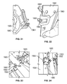
- FIG. 18 is a perspective view of a plate to be used with a sixth embodiment of the invention.
- FIG. 19 is a perspective view of a clip to be used with a sixth embodiment of the invention.
- FIG. 20 is a perspective view of another clip to be used with a sixth embodiment of the invention.
- FIG. 21 is a perspective view of the clip shown in FIG. 19 .
- FIG. 22 illustrates the attachment of clips to the base.
- FIG. 23 is a perspective view of the clip shown in FIG. 20 engaging a leg.
- FIG. 24 is a perspective view of the clip shown in FIG. 19 engaging the legs of a device.
- FIGS. 1 and 2 depict one embodiment of the invention comprising a retaining clip 100 that attaches to a plate 200 found on an ironing board (not shown) or on a device having folding legs.
- Clip 100 has a U-shaped clip 102 that releasably engages at least one folding leg (not shown).
- Clip 102 is dimensioned to releasably engage a tubular leg.
- Clip 100 attaches to base 200 by a compression fit that is created by a rectangular base 104 having a stop 106 on one edge that aligns with an edge 201 of plate 200 .
- base 104 includes a U-shaped portion 108 that defines an opening that engages edge 202 of plate 200 .
- base 104 also includes a stepped portion 110 that engages edge 206 of plate 200 by extending through opening 204 .
- clip 100 is attached to plate 200 by sliding stepped portion 110 through opening 204 while portion 108 is slid into position to engage edge 202 .
- Base 104 is sized such that once edges 201 , 202 and 206 are contacted, a compression fit is created that affixes clip 100 to base 200 .
- U-shaped clip 102 is positioned to receive a supporting leg of a device so as to hold the folding leg of the device in a releasably secured position when the device is not in use.
- FIGS. 3 and 4 depict a second embodiment of the invention comprising a retaining clip 300 that attaches to a plate 400 found on an ironing board (not shown) or on a device having folding legs.
- Clip 300 includes a U-shaped clip 302 that releasably engages at least one folding leg (not shown).
- Clip 300 attaches to base 400 by a compression fit that is created by a rectangular base 304 having opposingly located U-shaped ends 308 - 309 that define openings that engage edges 402 - 403 of plate 400 .
- plate 400 also includes a boss 408 .
- clip 300 is attached to plate 400 by sliding base 304 along plate 400 until it passes over boss 408 .
- stops 410 - 411 and boss 408 lock the base in one direction and the engagement between edges 402 - 403 and U-shaped portions 308 - 309 lock the base in the other direction.
- FIGS. 5 through 8 illustrate another embodiment of the invention comprising a retaining clip 500 that attaches to a plate 600 found on an ironing board (not shown) or on a device having folding legs.
- Clip 500 has a U-shaped clip 502 that releasably engages at least one folding leg (not shown).
- Clip 500 attaches to base 600 by a compression fit that is created by a rectangular base 504 having extensions 510 - 511 that define apertures 512 - 513 .
- Apertures 512 - 513 are dimensioned to receive projections 603 and 604 of plate 600 .
- Clip 500 also includes J-shaped or curved sections 505 and 506 that are sized to engage J-shaped or curved channel 610 of base 600 .
- clip 500 is attached to plate 600 by engaging extensions 505 and 506 to one side of plate 600 so that the curved section 610 is located therein and then rotating the base towards projections 603 and 604 until projections 603 and 604 are positioned in apertures 512 - 513 thereby locking base 500 to plate 600 .
- sections 510 and 511 engage the other side of plate 600 .
- FIGS. 9 through 12 illustrate another embodiment of the invention comprising a retaining clip 700 that attaches to a plate 800 found on an ironing board (not shown) or on a device having folding legs.
- Clip 700 has a U-shaped clip 702 that releasably engages at least one folding leg (not shown).
- Clip 700 attaches to base 800 by a compression fit that is created by a rectangular base 704 having extensions 710 - 711 that engage one side of plate 800 that defines apertures 712 - 713 .
- Apertures 712 - 713 are dimensioned to receive projections 804 - 805 of plate 800 .
- a portion of each extension 710 - 711 is sized to fit into U-shaped channel 808 .
- clip 700 is attached to plate 800 by sliding projections 804 - 805 into apertures 712 - 713 to engage one side of the plate while extensions 710 - 711 are positioned in channel 808 and engage another side of the plate. Clamps 820 - 821 are then used to secure the clip to the plate. A boss 830 keeps clamp 821 from disengaging with a similarly positioned boss (not shown) to secure clamp 820 .
- FIGS. 13 and 14 depict another embodiment of the invention comprising a retaining clip 360 that attaches to a plate 460 found on an ironing board (not shown) or on a device having folding legs.
- Clip 360 includes a U-shaped clip 362 that releasably engages at least one folding leg (not shown).
- Clip 360 also includes sections 370 - 371 each having an extension 373 - 374 defining apertures 375 - 376 . To attach clip 360 , each section is slid over arms 462 and 463 and snapped together in ways known to those of skill in the art.
- FIGS. 15 through 17 illustrate another embodiment of the invention comprising a retaining clip 560 that attaches to a plate 660 found on an ironing board (not shown) or on a device having folding legs.
- Clip 560 has opposing semi-U-shaped clips 563 - 564 that releasably engage a section of two legs 900 and 901 as shown in FIGS. 16 and 17 .
- Clip 560 attaches to base 660 by a compression fit that is created by a rectangular base 565 that defines an opening 566 that receives a boss 665 of plate 660 .
- base 560 has a portion 570 that creates a U-shaped channel that is sized to receive and slide over edge 670 with each section of the channel engaging an opposingly located side of the plate. As base 560 is slid over edge 670 angled boss 665 engages and is received in opening 565 . Once fully engaged, base 560 is locked in place.
- base 560 could be configured as described above for the other described embodiments to deploy a single U-shaped leg locking clip to engage a single leg such as leg 900 .
- the semi-U-shaped clips shown in FIGS. 16 and 17 may also be used instead of the U-shaped leg locking clips shown in the prior embodiments in the event more than one leg is needed to be secured.
- tubular legs have been shown, the invention is not so limited and the teaching described above may be used with any leg configuration and shape by simply designing the leg locking clip to be complimentary in shape.
- the bosses described above may also be angled as shown to promote ease of use.
- FIGS. 18 through 24 illustrate another embodiment of the invention comprising a retaining clip 1560 that attaches to a plate 1660 found on an ironing board 1900 or on a device having folding legs.
- Clip 1560 has opposing semi-U-shaped clips 1563 - 1564 that releasably engage a section of two legs 1902 and 1904 as shown in FIG. 24 .
- Clip 1560 may also have opposing semi-U-shaped clips 1565 - 1566 that releasably engage a section of leg 1903 as shown in FIG. 23 .
- Clip 1560 attaches to base 1660 by a compression fit that is created by a rectangular base 1565 that defines an opening 1566 ( FIG. 22 ) that receives a boss 1665 ( FIGS. 18 and 22 ) of plate 1660 .
- base 1560 has a portion 1570 that creates a U-shaped channel that is sized to receive and slide over edge 1670 while each section of the channel engages an opposingly located side of the plate.
- boss 1665 acts as a locking member that engages and is received in opening 1565 . Once fully engaged, boss 1561 locks base 1560 in place.
- all embodiments described above may be configured to deploy a single U-shaped clip to engage a single leg such as leg 1903 .
- the semi-U-shaped clips may also be configured to secure multiple legs 1902 and 1904 as shown.
- tubular legs have been shown, the invention is not so limited and the teachings described above may be used with any leg configuration and shape by simply designing the clip to be complimentary in shape.
- bosses described above may also be angled as shown to promote ease of use.
Landscapes
- Engineering & Computer Science (AREA)
- General Engineering & Computer Science (AREA)
- Mechanical Engineering (AREA)
- Textile Engineering (AREA)
- Clamps And Clips (AREA)
Abstract
Description
Claims (9)
Priority Applications (1)
| Application Number | Priority Date | Filing Date | Title |
|---|---|---|---|
| US14/624,436 US9435071B2 (en) | 2014-02-17 | 2015-02-17 | Leg retaining clip |
Applications Claiming Priority (2)
| Application Number | Priority Date | Filing Date | Title |
|---|---|---|---|
| US201461940520P | 2014-02-17 | 2014-02-17 | |
| US14/624,436 US9435071B2 (en) | 2014-02-17 | 2015-02-17 | Leg retaining clip |
Publications (2)
| Publication Number | Publication Date |
|---|---|
| US20150233047A1 US20150233047A1 (en) | 2015-08-20 |
| US9435071B2 true US9435071B2 (en) | 2016-09-06 |
Family
ID=53797604
Family Applications (1)
| Application Number | Title | Priority Date | Filing Date |
|---|---|---|---|
| US14/624,436 Expired - Fee Related US9435071B2 (en) | 2014-02-17 | 2015-02-17 | Leg retaining clip |
Country Status (1)
| Country | Link |
|---|---|
| US (1) | US9435071B2 (en) |
Cited By (3)
| Publication number | Priority date | Publication date | Assignee | Title |
|---|---|---|---|---|
| USD800542S1 (en) * | 2016-07-13 | 2017-10-24 | Crospon Limited | Clip |
| USD801160S1 (en) * | 2016-10-06 | 2017-10-31 | Whitmor, Inc. | Ironing board lock |
| US20190150574A1 (en) * | 2014-05-06 | 2019-05-23 | Illinois Tool Works Inc. | Web-connecting assembly having a release button |
Citations (15)
| Publication number | Priority date | Publication date | Assignee | Title |
|---|---|---|---|---|
| US2685752A (en) * | 1952-12-26 | 1954-08-10 | Sr Francis V Healy | Collapsible ironing board |
| US2721407A (en) * | 1953-08-10 | 1955-10-25 | Hazel E Sutherland | Portable ironing board |
| US2785936A (en) | 1955-05-25 | 1957-03-19 | Cvikich Joseph | Folding table having u-shaped leg pairs each securable to underside at triangularly spaced points |
| US3093412A (en) * | 1961-10-16 | 1963-06-11 | Castro Convertible Corp | Convertible chair |
| US3265019A (en) | 1965-10-21 | 1966-08-09 | Raymond Haydock Jr | Tv snack table |
| US3512620A (en) * | 1968-05-21 | 1970-05-19 | Harry A Bell | Combination luggage case,ironing board and table |
| US5603267A (en) | 1993-10-15 | 1997-02-18 | Ino-Products Inc. | Folding table |
| US5667177A (en) * | 1994-04-18 | 1997-09-16 | Erico International Corporation | Spring snap clip |
| US6641093B2 (en) * | 2000-11-24 | 2003-11-04 | Newfrey Llc | Clip arrangement for releasably fastening an object to at least one line |
| US7225745B2 (en) | 2004-05-10 | 2007-06-05 | Home Products International, Inc. | Free standing ironing board |
| US7395620B1 (en) * | 2007-01-25 | 2008-07-08 | The Evercare Company | Ironing board assembly |
| US20090146021A1 (en) * | 2007-12-11 | 2009-06-11 | Becker Renae E | Clamp for interconnecting orthogonally oriented pipes |
| US20130047820A1 (en) * | 2010-04-08 | 2013-02-28 | The Stageworks Gear Company Ltd. | Drumstick holder |
| US20140252178A1 (en) * | 2009-05-27 | 2014-09-11 | Philip Allen Myers | Building Strut System |
| US20150090845A1 (en) * | 2013-09-30 | 2015-04-02 | Covidien Lp | Medical Device Supporting Apparatus |
-
2015
- 2015-02-17 US US14/624,436 patent/US9435071B2/en not_active Expired - Fee Related
Patent Citations (15)
| Publication number | Priority date | Publication date | Assignee | Title |
|---|---|---|---|---|
| US2685752A (en) * | 1952-12-26 | 1954-08-10 | Sr Francis V Healy | Collapsible ironing board |
| US2721407A (en) * | 1953-08-10 | 1955-10-25 | Hazel E Sutherland | Portable ironing board |
| US2785936A (en) | 1955-05-25 | 1957-03-19 | Cvikich Joseph | Folding table having u-shaped leg pairs each securable to underside at triangularly spaced points |
| US3093412A (en) * | 1961-10-16 | 1963-06-11 | Castro Convertible Corp | Convertible chair |
| US3265019A (en) | 1965-10-21 | 1966-08-09 | Raymond Haydock Jr | Tv snack table |
| US3512620A (en) * | 1968-05-21 | 1970-05-19 | Harry A Bell | Combination luggage case,ironing board and table |
| US5603267A (en) | 1993-10-15 | 1997-02-18 | Ino-Products Inc. | Folding table |
| US5667177A (en) * | 1994-04-18 | 1997-09-16 | Erico International Corporation | Spring snap clip |
| US6641093B2 (en) * | 2000-11-24 | 2003-11-04 | Newfrey Llc | Clip arrangement for releasably fastening an object to at least one line |
| US7225745B2 (en) | 2004-05-10 | 2007-06-05 | Home Products International, Inc. | Free standing ironing board |
| US7395620B1 (en) * | 2007-01-25 | 2008-07-08 | The Evercare Company | Ironing board assembly |
| US20090146021A1 (en) * | 2007-12-11 | 2009-06-11 | Becker Renae E | Clamp for interconnecting orthogonally oriented pipes |
| US20140252178A1 (en) * | 2009-05-27 | 2014-09-11 | Philip Allen Myers | Building Strut System |
| US20130047820A1 (en) * | 2010-04-08 | 2013-02-28 | The Stageworks Gear Company Ltd. | Drumstick holder |
| US20150090845A1 (en) * | 2013-09-30 | 2015-04-02 | Covidien Lp | Medical Device Supporting Apparatus |
Cited By (4)
| Publication number | Priority date | Publication date | Assignee | Title |
|---|---|---|---|---|
| US20190150574A1 (en) * | 2014-05-06 | 2019-05-23 | Illinois Tool Works Inc. | Web-connecting assembly having a release button |
| US11071356B2 (en) * | 2014-05-06 | 2021-07-27 | Illinois Tool Works Inc. | Web-connecting assembly having a release button |
| USD800542S1 (en) * | 2016-07-13 | 2017-10-24 | Crospon Limited | Clip |
| USD801160S1 (en) * | 2016-10-06 | 2017-10-31 | Whitmor, Inc. | Ironing board lock |
Also Published As
| Publication number | Publication date |
|---|---|
| US20150233047A1 (en) | 2015-08-20 |
Similar Documents
| Publication | Publication Date | Title |
|---|---|---|
| US10914333B2 (en) | Suspension assembly | |
| US9435071B2 (en) | Leg retaining clip | |
| AU2011201725B2 (en) | Self-centering ceiling panel | |
| US20180066437A1 (en) | Gutter hanger assembly | |
| EP3435821B1 (en) | Suspension system | |
| US10188006B2 (en) | Bracket mount assembly for light fixtures | |
| PL417485A1 (en) | Clamp for a collapsible structure | |
| US9377134B2 (en) | Hanger for an elongate article | |
| US20160316952A1 (en) | Kit of a hanging system | |
| RU2016115796A (en) | VENTILATION DEVICE | |
| CN110248565A (en) | Wearable device | |
| KR101502732B1 (en) | the support structure for a frame | |
| US20140263871A1 (en) | Gangable Conduit Hanger Assembly | |
| EP2360799A3 (en) | Adjustable clip | |
| US20170314597A1 (en) | Improvements in or relating to connecting devices | |
| US9642478B1 (en) | Expandable mounting apparatus for suspending objects on a wall | |
| US11208845B2 (en) | Ladder anchoring assembly | |
| RU2017145013A (en) | Mounting system for attaching a wall corner to a fluid conducting installation on a wall | |
| JP2008215014A (en) | Clip | |
| EP2937853A1 (en) | Tenterhook for tightening a cloth provided with fixing eyes in a tenter | |
| GB2535732A (en) | Barrier connector | |
| WO2014170438A3 (en) | Quick closure for a clamping device and clamping device | |
| Cloud | Adobe Creative Cloud | |
| JP6942880B2 (en) | Clips for fastening pipe-shaped or tube-shaped objects | |
| JP2008215015A (en) | Clip |
Legal Events
| Date | Code | Title | Description |
|---|---|---|---|
| ZAAA | Notice of allowance and fees due |
Free format text: ORIGINAL CODE: NOA |
|
| ZAAB | Notice of allowance mailed |
Free format text: ORIGINAL CODE: MN/=. |
|
| AS | Assignment |
Owner name: HOMALLY INC., ILLINOIS Free format text: ASSIGNMENT OF ASSIGNORS INTEREST;ASSIGNORS:WELSH, THOMAS J., JR.;PD3D, INC.;REEL/FRAME:039384/0990 Effective date: 20160801 Owner name: PD3D, INC., ILLINOIS Free format text: ASSIGNMENT OF ASSIGNORS INTEREST;ASSIGNOR:WELSH, THOMAS J., JR.;REEL/FRAME:039384/0988 Effective date: 20160524 |
|
| STCF | Information on status: patent grant |
Free format text: PATENTED CASE |
|
| AS | Assignment |
Owner name: COMERCIALIZADORA DOS CINCO, S.A. DE C.V., MEXICO Free format text: ASSIGNMENT OF ASSIGNORS INTEREST;ASSIGNOR:HOMALLY INC.;REEL/FRAME:047303/0626 Effective date: 20180831 |
|
| FEPP | Fee payment procedure |
Free format text: MAINTENANCE FEE REMINDER MAILED (ORIGINAL EVENT CODE: REM.); ENTITY STATUS OF PATENT OWNER: SMALL ENTITY |
|
| FEPP | Fee payment procedure |
Free format text: SURCHARGE FOR LATE PAYMENT, SMALL ENTITY (ORIGINAL EVENT CODE: M2554); ENTITY STATUS OF PATENT OWNER: SMALL ENTITY |
|
| MAFP | Maintenance fee payment |
Free format text: PAYMENT OF MAINTENANCE FEE, 4TH YR, SMALL ENTITY (ORIGINAL EVENT CODE: M2551); ENTITY STATUS OF PATENT OWNER: SMALL ENTITY Year of fee payment: 4 |
|
| FEPP | Fee payment procedure |
Free format text: MAINTENANCE FEE REMINDER MAILED (ORIGINAL EVENT CODE: REM.); ENTITY STATUS OF PATENT OWNER: SMALL ENTITY |
|
| LAPS | Lapse for failure to pay maintenance fees |
Free format text: PATENT EXPIRED FOR FAILURE TO PAY MAINTENANCE FEES (ORIGINAL EVENT CODE: EXP.); ENTITY STATUS OF PATENT OWNER: SMALL ENTITY |
|
| STCH | Information on status: patent discontinuation |
Free format text: PATENT EXPIRED DUE TO NONPAYMENT OF MAINTENANCE FEES UNDER 37 CFR 1.362 |
|
| FP | Lapsed due to failure to pay maintenance fee |
Effective date: 20240906 |