US7635983B2 - Battery testing apparatus that controls a switch to allow current to flow from the battery to a utility power source - Google Patents
Battery testing apparatus that controls a switch to allow current to flow from the battery to a utility power source Download PDFInfo
- Publication number
- US7635983B2 US7635983B2 US11/651,038 US65103807A US7635983B2 US 7635983 B2 US7635983 B2 US 7635983B2 US 65103807 A US65103807 A US 65103807A US 7635983 B2 US7635983 B2 US 7635983B2
- Authority
- US
- United States
- Prior art keywords
- battery
- load
- switch
- tester
- mode
- Prior art date
- Legal status (The legal status is an assumption and is not a legal conclusion. Google has not performed a legal analysis and makes no representation as to the accuracy of the status listed.)
- Active - Reinstated, expires
Links
Images


Classifications
-
- H—ELECTRICITY
- H02—GENERATION; CONVERSION OR DISTRIBUTION OF ELECTRIC POWER
- H02J—CIRCUIT ARRANGEMENTS OR SYSTEMS FOR SUPPLYING OR DISTRIBUTING ELECTRIC POWER; SYSTEMS FOR STORING ELECTRIC ENERGY
- H02J7/00—Circuit arrangements for charging or depolarising batteries or for supplying loads from batteries
- H02J7/0029—Circuit arrangements for charging or depolarising batteries or for supplying loads from batteries with safety or protection devices or circuits
- H02J7/0031—Circuit arrangements for charging or depolarising batteries or for supplying loads from batteries with safety or protection devices or circuits using battery or load disconnect circuits
-
- H—ELECTRICITY
- H02—GENERATION; CONVERSION OR DISTRIBUTION OF ELECTRIC POWER
- H02J—CIRCUIT ARRANGEMENTS OR SYSTEMS FOR SUPPLYING OR DISTRIBUTING ELECTRIC POWER; SYSTEMS FOR STORING ELECTRIC ENERGY
- H02J7/00—Circuit arrangements for charging or depolarising batteries or for supplying loads from batteries
- H02J7/0047—Circuit arrangements for charging or depolarising batteries or for supplying loads from batteries with monitoring or indicating devices or circuits
- H02J7/005—Detection of state of health [SOH]
-
- G—PHYSICS
- G01—MEASURING; TESTING
- G01R—MEASURING ELECTRIC VARIABLES; MEASURING MAGNETIC VARIABLES
- G01R31/00—Arrangements for testing electric properties; Arrangements for locating electric faults; Arrangements for electrical testing characterised by what is being tested not provided for elsewhere
- G01R31/36—Arrangements for testing, measuring or monitoring the electrical condition of accumulators or electric batteries, e.g. capacity or state of charge [SoC]
- G01R31/3644—Constructional arrangements
- G01R31/3648—Constructional arrangements comprising digital calculation means, e.g. for performing an algorithm
Definitions
- UPS uninterruptible power supply
- the first approach simulates a failure of the utility line, transfers the load to the UPS, and measures the battery parameters. This approach risks the possibility that the load will not be supported when the test is initialized.
- a second approach utilizes additional contactors that switch load resistors across the batteries when a test is initialized. This approach adds cost, complexity, and the resistor loss becomes unmanageable for large systems.
- An electronic battery test system is disclosed that will illustrate a simple, low cost, method for testing the batteries under load without risking the capability to support the load at any time during the test.
- the system is comprised of a battery charger, batteries, and an inverter with a control system.
- the system is for use with a utility line, and load.
- This invention can be used in any system that contains a battery charger operated from an AC utility source that is directed in determining the health of a battery without compromising the back-up capability of the system.
- UPS systems to back up critical loads.
- the double conversion topology has a separate battery charger that operates from the AC line connected to the batteries and a separate output source that supplies the battery power to the loads.
- the output source could convert the battery to an AC output or a DC output.
- Off-line systems use the same inverter to either charge the batteries or support the load. When power from the utility line is present then it is passed to the load and the batteries are charged through the inverter. When the utility line fails the inverter switches from battery charging mode to inverting mode and the load is supplied by the batteries via the inverter.
- Prior art methods have the following disadvantages with respect to battery testing. Some methods require batteries to be taken out of service, which risks that the load will not be supported in the event of an AC line failure. Other methods simulate a utility line failure and transfer to inverter to support the load; however, this poses a risk that the load is not supported if a battery has failed since the last test. Other methods of testing batteries require extra controllers, power switches to disconnect and reconnect the batteries, and a separate load that is large, costly, and inefficient for larger systems.
- the present invention addresses the aforementioned limitations of the prior art by providing an apparatus and method that offers manual or programmable test features under micro-controller supervision that does not risk the load being dropped during the testing period.
- the battery test is performed by drawing a current from the battery and supplying that current into the utility grid. During the testing period battery parameters are monitored, tests results are saved, and alarms are generated based on historical data predicting battery degradation or weakness.
- the live circuit battery tester uses all common hardware with the battery charger and does not require additional disconnects or load banks.
- UPS uninterruptible power supply
- Another aspect of the present invention allows the battery testing to be performed without disconnection of the load or the risk of not supporting the loads before, during, or after the testing occurs.
- Yet another object of the present invention is to provide a control system for monitoring, collecting, and storing measured data. This data is used to determine weakening, failed, or poor connections in the battery system.
- a further object of the present invention is to use the stored data to form a historical database to provide information about the degradation of the battery system over time.
- This invention provides an arrangement for testing a battery connected to a battery charger and with the capability to support a critical load.
- an off-line UPS topology is chosen to illustrate the invention.
- the control for the UPS is comprised of three modes of operation: battery charging, battery backup, and battery testing.
- the AC utility source is connected or disconnected to the load via a static switch.
- the control will phase lock to the AC utility source, pass the source to the load, and charge the batteries by regulating the charging current to the batteries.
- the second control mode is activated when the utility line reaches an out of tolerance condition.
- the control will disconnect the AC utility source, instantaneously switch from battery charging mode to battery back-up mode and the load is supported by the battery through the inverter.
- the third control mode battery testing, is activated by a user command or automatically by a pre-programmed set point in the control. Prior to entering battery test mode, three conditions must exist before the control will allow a transition from battery charging mode to battery test mode. The first condition is that the control mode must be in battery charging mode when the command is issued. The second condition is that the batteries must be at 100% capacity as calculated by the control and the third condition is that the battery has been at 100% capacity for a specified interval that is programmable.
- the control During battery test mode the control remains phase locked to the AC utility source, ramps down the battery charging current, begins to draw power from the batteries, and exports the power to the utility line. Throughout the battery test period the utility line is continuously monitored and never disconnected from the load so there is no possibility of load disruption. If the utility line fails during the battery test the control can instantaneously switch from battery test mode to battery back-up mode, abandoning battery test mode and providing full support to the load.
- the invention further utilizes the capacity of software systems to measure in circuit, under load, battery parameters including: individual battery cell voltages, battery string currents, and battery temperatures.
- the analysis of the data will provide a direct correlation to the health of the batteries during this test. This information is stored and adds to a historical trend of test results that predicts weaknesses arising in the battery system over a longer period.
- the present invention provides a useful method for battery testing to determine a weakened or bad storage battery on which a system relies, without compromising backup operation of the system by allowing power to be drawn from the storage battery and supplied to the utility line without disconnecting the load from the utility source.
- discharge parameters are measured and compared to historical data to determine weakened or bad batteries, and annunciations are provided to make the user aware of potential problems with the storage battery system.
- the present invention uses the same hardware to perform battery charging, battery testing, and battery backup, and an inverter function if required.
- the battery tester phase locks to the utility source, removes power from the storage battery, and routes the power into the utility line for a specified period of time. When the battery test is complete the system resumes charging the batteries.
- a battery test includes drawing a fixed load from the batteries over a specified length of time.
- Storage battery parameters are measured initially, during, and at the end of the test. These parameters are per unitized and compared to historical data.
- Historical data can be initial test data as well as the last 100 tests, and every 100 th test. The historical data is compared against threshold values to determine a weakened or failed battery.
- Alarms or faults are created to identify a problem with the battery system. These alarms and faults are transmitted via a display panel, digital I/O, or through a communication port.
- FIG. 1A is a simplified block diagram of the elementary topology of the battery charger/tester.
- FIG. 1B is a block diagram of the battery charger/tester during battery charging mode illustrating power flow direction.
- FIG. 1C is a block diagram of the battery charger/tester during battery testing mode illustrating power flow direction.
- FIG. 2A is a simplified block diagram of a DC Load UPS topology with the built in electronic battery tester.
- FIG. 2B is a block diagram of a DC Load UPS topology during battery charging mode illustrating power flow direction.
- FIG. 2C is a block diagram of a DC Load UPS topology during battery testing mode illustrating power flow direction.
- FIG. 2D is a block diagram of a DC Load UPS topology during battery backup mode illustrating power flow direction.
- FIG. 3A is a simplified block diagram of a double conversion AC UPS topology with a built in electronic battery tester.
- FIG. 3B is a block diagram of a double conversion AC load UPS topology during battery charging mode illustrating power flow direction.
- FIG. 3C is a block diagram of a double conversion AC load topology during battery testing mode illustrating power flow direction.
- FIG. 3D is a block diagram of a double conversion AC load UPS topology during battery backup mode illustrating power flow direction.
- FIG. 4A is a simplified block diagram of an off line AC UPS topology with the built in electronic battery tester.
- FIG. 4B is a block diagram of an off line topology during battery charging mode illustrating power flow direction.
- FIG. 4C is a block diagram of an off line topology during battery testing mode illustrating power flow direction.
- FIG. 4D is a block diagram of an off line topology during battery backup mode illustrating power flow direction.
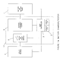
- FIG. 5A is a block diagram illustrating the functions that exist in the main controller.
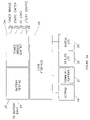
- FIG. 5B is a block diagram illustrating the battery testing section of the main controller.
- FIG. 1A represents the simplest form factor of the present invention with an integral, in circuit, electronic battery testing section 11 .
- the battery testing section 11 includes: a battery charger/tester 9 , a controller 12 , and a static switch or relay 6 .
- the battery testing section 11 is connected between a battery or battery bank 1 and a utility source 7 .
- the electronic battery testing section 11 includes two modes of operation: battery charging mode and battery testing mode. The mode of operation is determined and can be changed by the main controller 3 based on status signals fed back from the utility source 7 , the analog/digital IO 2 , and the battery bank 1 .
- the analog/digital I/O 2 is the communication line to the user that allows transmission of information about the testing as well as reception of commands that execute functions related to the operation of the system.
- the analog and digital I/O suite includes dry contacts, lights, display panel with keypad, and communication ports (RS-232, Ethernet, TCIP, etc.).
- FIG. 1B represents a simplified connection diagram for battery charging mode (mode 1 ).
- the battery charging mode is the normal operating mode for the battery charger/tester topology.
- the static switch 6 is a bi-directional switch that allows current to flow in either direction when closed and no current to flow when it is open. The function of the static switch 6 is two-fold; first and foremost it prevents the battery charger/tester 9 from supplying power to the utility source 7 when the utility source 7 is not present, i.e., when there is no utility voltage. Secondly, it allows a means to connect and disconnect the utility source 7 under certain conditions.
- phase lock describes a condition that exists when the main controller's simulated sine wave reference is in phase with the utility source's voltage waveform. Once phase lock is commanded the main controller 3 adjusts its natural oscillator frequency until it meets the frequency of the utility source 7 and remains locked on the frequency of the utility source 7 until the voltage or frequency of the utility source drifts out of tolerance.
- the main controller 3 closes the static switch 6 .
- the battery charger/tester 9 has the utility source 7 available to charge the battery bank 1 through power lines 19 , 20 , 23 , and 24 .
- the battery bank 1 is connected to the battery charger/tester 9 via a positive connection 13 and a negative connection 14 .
- the battery charger/tester 9 receives commands from the main controller 3 through control lines 30 and, in mode 1 , is responsible transforming the AC current from the utility source 7 through the static switch 6 via power lines 23 and 24 , to the battery charger/tester 9 through power lines 19 and 20 and to DC current required by the battery bank 1 .
- the main controller 3 senses the utility source 7 via control signals 28 and phase locks to the incoming utility source 7 . Once phase lock is established and maintained, the main controller 3 closes the static switch 6 through control lines 26 providing power from the utility source 7 to the battery charger/tester 9 . The main controller 3 then begins to switch the battery charger tester 9 via control lines 30 drawing current from the utility source 7 and supplying current to the battery bank 1 . During this charging process, the main controller 3 monitors the battery bank through control sense lines 29 to regulate and monitor the charging event.
- the arrows denoted by 47 , 48 , and 49 describe the current flow at one particular instant of time.
- the current will flow from the utility source 7 to the battery charger/tester 9 through the static switch 6 via path 47 and 48 .
- the battery charger/tester will transform the current and charge the battery bank 1 via path 49 .
- FIG. 1C represents a simplified connection diagram for battery testing mode (mode 2 ).
- Battery testing mode will draw power from the battery bank 1 and direct it into the utility source 7 .
- the main controller 3 In order to perform this function the main controller 3 must be phase locked to the utility source 7 , just as in battery charging mode. Once phase locked, the main controller 3 produces a current reference and switches the battery charger tester 9 so that current is drawn from the battery bank 1 and directed to the utility source 7 .
- This method of testing has the following advantages: First, by controlling the power flow into the utility source 7 , a consistently repeatable power draw from the battery will occur reducing the error in detection of a weakened battery. This stems from the fact that batteries have a large set of independent variables that affect the state of battery health, one of which is load draw.
- the required components are reduced because a separate power bridge is not required for battery charging, battery testing, and battery back-up, rather only one power bridge is needed for all three modes. Moreover, by utilizing the same main controller 3 for battery testing, battery charging, and battery backup modes, the speed of response from one mode to another is extremely fast.
- the main controller 3 Before attempting to switch to battery testing mode, the main controller 3 ensures the following three conditions exist. First, battery charging mode (mode 1 ) is the mode of operation. Second, the calculated battery capacity is 100%. Battery capacity is defined as the percent of charge remaining in the battery. The main controller 3 calculates the charge into and out of the battery bank 1 via control line 29 and increases the battery capacity during charging mode (mode 1 ). Third, after the battery has reached 100% capacity, a timer is started and once the specified interval, that is programmable from 12 hr to 48 hrs, is exhausted battery testing mode can be activated. If the main controller 3 detects an out of tolerance condition on the utility source 7 through control lines 28 it will abort battery testing, mode 2 , and instantaneously disconnect from the utility source 7 . This set of rules enforced by the main controller 3 ensures that the testing begins from the same conditions each time; a fully charged battery bank.
- a command to enter battery testing mode is received by the main controller 3 from one of the following means; analog I/O 2 , digital I/O 2 , or the main controller 3 itself. Once a command is received, the main controller 3 reduces the battery charging current to zero and starts to ramp up the current command slowly in the reverse direction until the desired set point is reached. By reversing the command, current will begin flowing from the battery 1 through the battery charger/tester 9 via power lines 13 and 14 . The current will enter the static switch 6 via power lines 19 and 20 and supply the current into the utility source 7 by means of power lines 23 and 24 .
- the arrows denoted by 50 , 51 , and 52 describe the current flow at one particular instant of time.
- the current will flow from the battery 1 through the battery charger/tester 9 through path 50 and from the battery charger/tester 9 to the static switch 6 via path 51 .
- the current will pass through the static switch 6 and into the utility source 7 via path 52 .
- FIG. 2A represents a DC Load UPS with an integral, in circuit, electronic battery testing section 11 .
- the battery testing section 11 includes: a battery charger/tester 9 , a controller 3 , and a static switch or relay 6 .
- Section 11 is mechanical, electrical, and functional identical to FIG. 1A .
- the main difference between the simple battery charger/tester and the DC Load UPS is the presence of a DC Load.
- FIG. 2B is a simplified block diagram of the DC Load UPS showing the current flow in battery charging mode.
- the description and function of battery charging mode is exactly the same as the case for FIG. 1B into the battery charger/tester 9 .
- a load node 58 was added to simplify the understanding of current flow in the different modes of operation of the DC Load UPS. The sum of the current flow into and out of the load node 58 must always equal zero.
- the main controller 3 senses the utility source 7 via control signals 28 and phase locks to the incoming utility source 7 . Once phase lock is established and maintained, the main controller 3 closes the static switch 6 through control lines 26 providing power from the utility source 7 to the battery charger/tester 9 . The main controller 3 then begins to switch the battery charger tester 9 via control lines 30 drawing current from the utility source 7 and supplying current to the battery bank 1 as well as the required current for the DC Load 73 . During this charging process, the main controller 3 monitors the battery bank through control sense lines 29 to regulate and monitor the charging event.
- the arrows denoted by 54 , 55 , 56 , 57 , and 59 describe the current flow at one particular instant of time.
- the battery charger/tester will transform the current and charge the battery bank 1 via path 56 into the load node 58 .
- the load will demand a certain portion of that current flowing through path 59 to the load.
- the remainder of the current will charge the battery bank via path 57 .
- FIG. 2C is a block diagram showing the current flow, during battery testing mode, for a DC Load UPS.
- Battery testing mode requires all of the same conditions previously described for FIG. 1C .
- the main difference is the presence of a DC Load 73 which requires continuous power during transitions between modes.
- the current flow into the load node 58 from the battery 1 via path 63 is monitored via control lines 29 .
- the main controller 12 begins switching the battery charger/tester 9
- the current into the load node 58 is regulated to a predetermined set point.
- the current fed into the battery charger/tester 9 via path 62 is the excess current not required by the DC Load 73 . This ensures the current draw from the battery bank 1 is repeatable each test.
- the dc current is switched into ac current by the battery charger/tester 9 and sent through the static switch via path 61 . During this mode the static switch is closed allowing the current to flow into the utility line via path 60 .
- FIG. 2D represents a simplified connection diagram for battery backup mode (mode 3 ).
- the main controller 3 switches to battery backup mode any time the utility source is out of tolerance.
- the main controller 3 must be able to switch to this mode extremely quickly from any other mode to ensure the load is fully supported.
- the present invention enables extremely fast transfer times between any two modes of operation while always ensuring that the DC load 73 is supported at all times. In the case of a DC Load, quick transfer times are realized because there are no devices between the battery 1 and the dc load 73 to interrupt current flow.
- battery backup mode (mode 3 ) is entered battery testing mode (mode 2 ) is disabled.
- FIG. 3A represents an on line double conversion ups with an integral, in circuit, electronic battery testing section 5 .
- the UPS 74 consists of a battery charger/tester 9 , a controller 3 , a static switch or relay 6 , and a dc-ac inverter 4 .
- the operation of the battery charging/testing part of the system that includes the battery charger/tester 9 , the static switch 6 , and the main controller 3 function identically to the DC Load UPS, FIG. 2A , as previously described.
- a dc/ac inverter power section 4 is required to invert the batteries dc voltage to an ac voltage to support the AC load 8 .
- FIG. 3B is a simplified block diagram of the on line double conversion UPS showing the current flow in battery charging mode.
- the description and function of battery charging mode is exactly the same as the case for FIG. 2B into the battery charger/tester 9 .
- the sum of the current flow into and out of the load node 58 must always equal zero.
- the main controller 3 senses the utility source 7 via control signals 28 and phase locks to the incoming utility source 7 . Once phase lock is established and maintained, the main controller 3 closes the static switch 6 through control lines 26 providing power from the utility source 7 to the battery charger/tester 9 . The main controller 3 then begins to switch the battery charger tester 9 via control lines 30 drawing current from the utility source 7 and supplying current to the battery bank 1 as well as the required current for the dc to ac inverter 4 . The main controller 3 will switch the dc/ac inverter 4 via control lines 30 to produce an ac voltage that will supply the ac load 8 . During this charging process, the main controller 3 monitors the battery bank through control sense lines 29 to regulate and monitor the charging event.
- the arrows denoted by 54 , 55 , 56 , 57 , 59 and 67 describe the current flow at one particular instant of time.
- the battery charger/tester will transform the current and charge the battery bank 1 via path 56 into the load node 58 .
- the dc to ac inverter 4 will demand a certain portion of that current flowing through path 59 to supply the ac load 8 via path 67 .
- the remainder of the current will charge the battery bank via path 57 .
- FIG. 3C is a block diagram showing the current flow, during battery testing mode, for an on line double conversion UPS.
- Battery testing mode requires all of the same conditions previously described for FIG. 2C .
- the main difference is the current flow out of the load node 58 from the battery 1 via path 64 feeds a dc-ac inverter 4 versus a dc load.
- the main controller 3 begins switching the battery charger/tester 9 , the current into the load node 58 is regulated to a predetermined set point.
- the current fed into the battery charger/tester 9 via path 62 is the excess current not required by the dc/ac inverter 4 . This ensures the current draw from the battery bank 1 is repeatable each test.
- the dc current is switched into ac current by the battery charger/tester 9 and sent through the static switch via path 61 . During this mode the static switch is closed allowing the current to flow into the utility line via path 60 .
- FIG. 3D represents a simplified connection diagram for battery backup mode (mode 3 ).
- the main controller 3 switches to battery backup mode any time the utility source is out of tolerance.
- the main controller 3 must be able to switch to this mode extremely quickly from any other mode to ensure the load is fully supported.
- the present invention enables extremely fast transfer times between any two modes of operation while always ensuring that the AC load 8 is supported at all times.
- battery backup mode mode 3
- mode 2 battery testing mode
- In battery backup mode current is supplied, via lines 65 and 66 , from the battery bank 1 to dc/ac inverter 4 through power lines 71 and 72 .
- the main controller opens the static switch 6 through control lines 26 so no power can be back fed to the utility source 7 or from the utility source 7 to the AC load. Once the utility source 7 is within tolerance for a specified period of the time the main controller 3 will phase lock to the utility source 7 and close the static switch 6 . At this instant the main controller 3 switches from mode 3 , battery backup mode, to mode 1 , battery charging mode.
- FIG. 4A is a simplified block diagram of an off line UPS topology.
- This topology includes an electronic battery testing section 5 that includes: a battery charger/tester 9 and DC to AC inverter 4 connected to a battery bank 1 .
- the static switch or relay 6 is the element that connects the utility source 7 to the AC load 8 and battery charger/tester 9 /DC to AC inverter 4 .
- the electronic battery testing section 5 includes three modes of operation: battery charging mode, battery testing mode, and DC to AC inverter mode (battery backup mode). The mode of operation is determined and can be changed by the main controller 3 based on status signals fed back from the utility source 7 , the analog/digital IO 2 , and the battery bank 1 .
- the analog/digital I/O 2 is the communication line to the user that allows transmission of information about the testing as well as reception of commands that execute functions related to the operation of the system.
- the analog and digital I/O suite includes dry contacts, lights, display panel with keypad, and communication ports (RS-232, Ethernet, TCIP, etc.).
- FIG. 4B represents a simplified connection diagram for battery charging mode (mode 1 ).
- the battery charger/tester 9 , and DC to AC inverter 4 are illustrated in FIG. 2A generically as a power bridge 25 .
- the battery charging mode is the normal operating mode for the off line UPS topology.
- the utility source 7 charges the battery bank 1 as well as supports the AC load 8 .
- the static switch 6 is a bi-directional switch that allows current to flow in either direction when closed and no current to flow when it is open. The function of the static switch 6 is two-fold; first and foremost it prevents the power bridge 25 from supplying power to the utility source 7 when the utility source 7 is not present, i.e., when there is no utility voltage.
- phase lock describes a condition that exists when the main controller's simulated sine wave reference is in phase with the utility source's voltage waveform. Once phase lock is commanded the main controller 3 adjusts its natural oscillator frequency until it meets the frequency of the utility source 7 and remains locked on the frequency of the utility source 7 until the voltage or frequency of the utility source drifts out of tolerance. Being phase locked to the utility source 7 is a very important condition that must exist before entering mode 1 to ensure continuous power supply to the load during transition between modes.
- the main controller 3 closes the static switch 6 so that the AC load 8 is immediately supplied from the utility source 7 through power lines 21 , 22 , 23 , and 24 .
- the power bridge 25 has the utility source 7 available to charge the battery bank 1 .
- the battery bank 1 is connected to the power bridge 25 via a positive connection 13 and a negative connection 14 .
- the power bridge 25 receives commands from the main controller 3 through control lines 30 and, in mode 1 , is responsible transforming the AC current from the utility source 7 through the static switch 6 via power lines 23 and 24 , to the power bridge 25 through power lines 19 and 20 and to DC current required by the battery bank 1 .
- the main controller 3 senses the utility source 7 via control signals 28 and phase locks to the incoming utility source 7 . Once phase lock is established and maintained, the main controller 3 closes the static switch 6 through control lines 26 providing power from the utility source 7 through to the AC load 8 . Sense lines 27 provide the main controller 3 with information about the load voltage and current. The power bridge then begins to switch drawing current from the utility source 7 and supplies current to the battery bank 1 . During this charging process, the main controller 3 monitors the battery bank through control sense lines 29 to regulate and monitor the charging event.
- the arrows denoted by 15 , 16 , 17 , and 18 describe the current flow at one particular instant of time.
- the current will flow from the utility source 7 to the AC load 8 through the static switch 6 via path 16 and 17 as well as from the utility source 7 through the static switch 6 via path 16 and 18 to the power bridge 25 .
- the power bridge 25 will transform the current and charge the battery bank 1 via path 15 .
- FIG. 4C represents a simplified connection diagram for battery testing mode (mode 2 ).
- Battery testing mode will draw power from the battery bank 1 and direct it into the utility source 7 .
- the main controller 3 In order to perform this function the main controller 3 must be phase locked to the utility source 7 , just as in battery charging mode. Once phase locked, the main controller 3 produces a current reference and switches the power bridge 25 so that current is drawn from the battery bank 1 and directed to the utility source 7 .
- This method of testing has the following advantages: First, it does not risk losing power supply to the load if the utility line fails. Second, by controlling the power flow into the utility source 7 , a consistently repeatable power draw from the battery will occur reducing the error in detection of a weakened battery.
- the required components are reduced because a separate power bridge is not required for battery charging, battery testing, and battery back-up, rather only one power bridge is needed for all three modes. Moreover, by utilizing the same main controller 3 for battery testing, battery charging, and battery backup modes, the speed of response from one mode to another is extremely fast.
- the main controller 3 Before attempting to switch to battery testing mode, the main controller 3 ensures the following three conditions exist. First, battery charging mode (mode 1 ) is the mode of operation. Second, the calculated battery capacity is 100%. Battery capacity is defined as the percent of charge remaining in the battery. The main controller 3 calculates the charge into and out of the battery bank 1 via control line 29 and increases the battery capacity during charging mode (mode 1 ) or decreases the battery capacity during battery backup mode (mode 3 ). Third, after the battery has reached 100% capacity, a timer is started and once the specified interval, that is programmable from 12 hr to 48 hrs, is exhausted battery testing mode can be activated.
- main controller 3 If the main controller 3 detects an out of tolerance condition on the utility source 7 through control lines 28 it will abort battery testing, mode 2 , and instantaneously switch to battery backup, mode 3 .
- This set of rules enforced by the main controller 3 ensures that there is no disruption to the AC load 8 due to battery testing command and that the testing begins from the same conditions each time; a fully charged battery bank.
- a command to enter battery testing mode is received by the main controller 3 from one of the following means; analog I/O 2 , digital I/O 2 , or the main controller 3 itself.
- the main controller 3 reduces the battery charging current to zero and starts to ramp up the current command slowly in the reverse direction until the desired set point is reached.
- current will begin flowing from the battery 1 through the power bridge 25 via power lines 13 and 14 .
- the current will enter the static switch 6 via power lines 19 and 20 and supply the current to the AC load 8 through power lines 21 and 22 . Once the power exceeds the AC load's 8 requirement, the excess will be exported to the utility source 7 by means of power lines 23 and 24 .
- the arrows denoted by 31 , 32 , 33 , and 17 describe the current flow at one particular instant of time.
- the current will flow from the battery 1 through the power bridge 25 through path 31 and from the power bridge 25 to the static switch 6 via path 32 .
- the current is larger than the AC load 8 requires, so the AC load 8 will consume the current it requires through path 17 and the remainder will be exported to the utility source 7 via path 33 .
- FIG. 4D represents a simplified connection diagram for battery backup mode (mode 3 ).
- the main controller 3 switches to battery backup mode any time the utility source is out of tolerance.
- the main controller 3 must be able to switch to this mode extremely quickly from any other mode to ensure the load is fully supported.
- the present invention enables extremely fast transfer times between any two modes of operation while always ensuring that the AC load is supported at all times. Such quick transfer times are realized because the same hardware (battery bank 1 , power bridge 25 , static switch 6 , and main controller 3 ) is used for all three modes of operation.
- battery backup mode mode 3
- battery testing mode mode 2
- power is supplied from the battery bank 1 to the power bridge 25 through power lines 13 and 14 .
- the power bridge will invert the DC voltage to an AC voltage at the proper amplitude and frequency.
- Required power is supplied to the AC load 8 via power lines 19 and 20 .
- the main controller opens the static switch 6 through control lines 26 so no power can be back fed to the utility source 7 or from the utility source 7 to the AC load.
- the main controller 3 will phase lock to the utility source 7 and close the static switch 6 allowing the AC load 8 to become supported by the utility source 7 .
- the main controller 3 switches from mode 3 , battery backup mode, to mode 1 , battery charging mode.
- FIG. 5A is a block diagram of the functions within the main controller 3 . From a high level view, the main controller 3 can be divided into three major functions: Battery testing 33 , power bridge control 34 , and user interface control 35 .
- the battery testing 33 section of the controller is responsible for the following functions: measuring the battery parameters through feedback sensing line 29 , per unitizing the calculations (so direct comparisons can be correlated), comparing the results to predefined set points, initiating alarms based on the results indicating weakened or failed batteries, and management of the test information over many test cycles.
- the power bridge control 34 is tasked to ensure the proper mode is activated, control the gating commands for all power devices in the bridge, process feedback signals, and manage all of the regulating loops.
- the user interface 35 receives its commands from I/O and sends the information to the main controller for processing.
- the data can come from analog I/O 38 , digital I/O 39 , a communications port that can be serial or parallel 37 , or entered through a keypad 36 .
- FIG. 5B illustrates the battery testing portion 33 of the main controller 3 , which can be further reduced into three categories of functions: new data collection 41 , communication 42 , and memory map 44 , 45 , and 46 .
- the communication section 42 of the battery testing block 33 , is used to transmit information to and from the main controller 3 .
- Alarms, faults, status of the test is the type of information that is passed to the main controller 3 and when a test will be performed, how long the test will be performed, how much load to draw from the battery is the type of information that is passed from the main controller 3 .
- the data collection block 41 measures the battery parameters and per unitizes the information for correlation.
- the battery parameters measured are voltage, temperature, and current.
- the battery current sensor is used to ensure the load draw on the battery is consistent.
- the battery voltages are used to determine the pass or fail criteria following the execution of a battery test. Temperature sensing allows a correction on the battery capacity calculation to improve the repeatability of the tests through varying environmental conditions.
- the main controller 3 will ensure the battery capacity is at 100% for a significant period of time before the test will be executed. This requirement ensures the battery is at a fully charged state, if possible, at the beginning of the battery test.
- the test method allows for the same exact load draw on each battery test performed. This is accomplished by being able to use the utility source 7 as an infinite current sink so if AC load 8 draw is not enough to load the battery to the desired set point, the remaining load draw required can be exported to the utility source 7 .
- the temperature data is used to compensate the battery capacity calculation so if a test is performed at a colder or hotter temperature the result is the same as if it were performed at a base temperature.
- the method of determining a weakening battery is completely dependant on the past performance over time of that specific battery, which individualizes the data for each battery or battery bank and makes decisions based on the historical data for the specific battery or battery bank.
- birth data 44 is information stored at the initial commissioning of the system or any time a battery is replaced.
- Short term data 46 is the last 100 results of the battery test.
- Long term data 45 is the last result (the 100 th result of the short term data) prior to rewriting over location 1 .
- Long term data is effectively test 100, 200, 300 etc. These numbers are exemplary and can be set according to the needs of the particular environment and the testing requirements.
- the battery test is performed creating the birth data. This data is saved in a specified memory location as the initial data. This data will be retained in memory until the startup procedure is executed again, in the case that all batteries are changed, or each individual battery can be reset for the case that one battery is replaced.
- a summary of the battery test mode is as follows: A command is received to perform the battery test and the main controller 3 determines that adequate time has elapsed to enable the battery bank 1 to be fully charged and the system is in the proper mode.
- the main controller 3 begins the battery test by decreasing the battery charging reference to zero and then proceeds to increase the battery testing current reference.
- the battery testing reference is increased until the desired load draw is reached as measured by the battery current sensor.
- the battery capacity begins to decrease as load is taken from the battery bank 1 and injected into the utility source 7 . Once the battery capacity is decreased to 75% the battery test is complete.
- the interim measurements are used as a coarse determination of a failing battery. Battery voltages are collected at different intervals throughout the testing period.
- an alarm will be generated.
- Three comparisons are made with the newly generated data. First a comparison is made between the new test data and the stored test data resulting from the twenty-fifth prior test. If the results differ by 20% an alarm is generated. Next, the main controller 3 performs a comparison between the new test data and the most recent long term test data. If the results vary by more than 50% an alarm is generated. Finally a comparison of the new test data is made with the birth data and if the results vary more than 75% an alarm is generated.
- the data is stored in memory so that historical logs, time and date stamped, are kept for each of the tests. The memory will hold data for previous 100 consecutive tests before rewriting over the oldest data.
- the historical information is stored and can be exported to a database so a user can analyze and make determinations about possible weakening batteries through trending analysis.
Landscapes
- Engineering & Computer Science (AREA)
- Power Engineering (AREA)
- Health & Medical Sciences (AREA)
- General Health & Medical Sciences (AREA)
- Medical Informatics (AREA)
- Charge And Discharge Circuits For Batteries Or The Like (AREA)
Abstract
Description
Claims (15)
Priority Applications (1)
| Application Number | Priority Date | Filing Date | Title |
|---|---|---|---|
| US11/651,038 US7635983B2 (en) | 2007-01-09 | 2007-01-09 | Battery testing apparatus that controls a switch to allow current to flow from the battery to a utility power source |
Applications Claiming Priority (1)
| Application Number | Priority Date | Filing Date | Title |
|---|---|---|---|
| US11/651,038 US7635983B2 (en) | 2007-01-09 | 2007-01-09 | Battery testing apparatus that controls a switch to allow current to flow from the battery to a utility power source |
Publications (2)
| Publication Number | Publication Date |
|---|---|
| US20080164762A1 US20080164762A1 (en) | 2008-07-10 |
| US7635983B2 true US7635983B2 (en) | 2009-12-22 |
Family
ID=39593649
Family Applications (1)
| Application Number | Title | Priority Date | Filing Date |
|---|---|---|---|
| US11/651,038 Active - Reinstated 2027-11-25 US7635983B2 (en) | 2007-01-09 | 2007-01-09 | Battery testing apparatus that controls a switch to allow current to flow from the battery to a utility power source |
Country Status (1)
| Country | Link |
|---|---|
| US (1) | US7635983B2 (en) |
Cited By (7)
| Publication number | Priority date | Publication date | Assignee | Title |
|---|---|---|---|---|
| US20100164290A1 (en) * | 2008-12-31 | 2010-07-01 | Powertech Industrial Co., Ltd. | Uninterruptible power supply and method of energy saving thereof |
| US20110133721A1 (en) * | 2008-06-25 | 2011-06-09 | Toyota Jidosha Kabushiki Kaisha | Method of diagnosing a malfunction in an abnormal voltage detecting apparatus, secondary battery system, and hybrid vehicle |
| US9466995B2 (en) | 2013-11-07 | 2016-10-11 | Stored Energy Systems, a Limited Liability Company | Self-contained automatic battery charging systems and methods |
| US9947497B2 (en) | 2014-09-30 | 2018-04-17 | Johnson Controls Technology Company | Integrated connector having sense and switching conductors for a relay used in a battery module |
| US9948125B2 (en) | 2013-11-07 | 2018-04-17 | Stored Energy Systems, a Limited Liability Company | Systems and methods for self-contained automatic battery charging and battery-life-extension charging |
| US10295611B2 (en) | 2015-06-09 | 2019-05-21 | Premier Technologies, Ltd. | Efficient battery tester |
| US12062935B2 (en) | 2022-06-30 | 2024-08-13 | Stored Energy Systems, LLC | Systems and methods for extending battery life |
Families Citing this family (18)
| Publication number | Priority date | Publication date | Assignee | Title |
|---|---|---|---|---|
| US20090243391A1 (en) * | 2008-03-31 | 2009-10-01 | Susong Iii Walter | Multi-functional power supply with power over ethernet support, integrated monitoring and supplemental power source backup |
| CN101561469A (en) * | 2008-04-18 | 2009-10-21 | 鸿富锦精密工业(深圳)有限公司 | Charger load simulator |
| WO2011037257A1 (en) | 2009-09-28 | 2011-03-31 | 日立ビークルエナジー株式会社 | Battery system |
| US9046582B1 (en) * | 2009-12-15 | 2015-06-02 | Emc Corporation | System and method for testing a battery |
| US8052230B2 (en) * | 2010-03-26 | 2011-11-08 | Richard Antony Vicek | “Handy kitchen”, pneumatically powered, movable cabinets |
| US9400314B2 (en) | 2010-04-15 | 2016-07-26 | Atc Logistics & Electronics, Inc. | Extended systems and methods for testing power supplies |
| US8988098B2 (en) | 2010-04-15 | 2015-03-24 | Atc Logistics & Electronics, Inc. | Systems and methods for modular testing of chargers |
| US10634731B2 (en) | 2010-04-15 | 2020-04-28 | FedEx Supply Chain Logistics & Electronics, Inc. | Systems and methods for testing power supplies |
| EP2678700B1 (en) * | 2011-02-21 | 2020-07-08 | Telefonaktiebolaget LM Ericsson (publ) | Arrangement and method for determining the state of a battery |
| TWI448886B (en) * | 2011-07-28 | 2014-08-11 | Quanta Comp Inc | Rack server system and control method thereof |
| US10121533B2 (en) | 2012-11-21 | 2018-11-06 | Nano-Retina, Inc. | Techniques for data retention in memory cells during power interruption |
| US9720477B2 (en) * | 2012-11-21 | 2017-08-01 | Nano-Retina, Inc. | Weak power supply operation and control |
| CN104569846B (en) * | 2015-01-23 | 2018-07-13 | 首都师范大学 | A kind of single battery test system |
| MX2018016360A (en) | 2015-03-18 | 2021-08-05 | Abl Ip Holding Llc | Power over ethernet emergency lighting system. |
| AT518008B1 (en) * | 2015-12-04 | 2021-11-15 | Leco Gmbh | Device for uninterrupted power supply to a consumer |
| US10677852B1 (en) * | 2017-11-07 | 2020-06-09 | Amazon Technologies, Inc. | Determining battery capacity |
| US11243260B2 (en) * | 2017-07-28 | 2022-02-08 | Northstar Battery Company, Llc | Systems and methods for determining an operating mode of a battery |
| US10770911B1 (en) | 2017-11-13 | 2020-09-08 | Amazon Technologies, Inc. | Calibrating battery fuel gages |
Citations (8)
| Publication number | Priority date | Publication date | Assignee | Title |
|---|---|---|---|---|
| US6172432B1 (en) * | 1999-06-18 | 2001-01-09 | Gen-Tran Corporation | Automatic transfer switch |
| US6204645B1 (en) * | 1998-09-11 | 2001-03-20 | Richard A. Cullen | Battery charging controller |
| US6526361B1 (en) | 1997-06-19 | 2003-02-25 | Snap-On Equipment Limited | Battery testing and classification |
| US20050007074A1 (en) | 2002-01-08 | 2005-01-13 | Siemens Aktiengesellschaft | Method for assessment of the state of batteries in battery-supported power supply systems |
| US20050184593A1 (en) | 1994-03-03 | 2005-08-25 | American Power Conversion Corporation | Battery communication system |
| US6983212B2 (en) | 2001-11-27 | 2006-01-03 | American Power Conversion Corporation | Battery management system and method |
| US6992487B1 (en) | 2003-05-29 | 2006-01-31 | La Marche Manufacturing Co. | Arrangement for testing battery while under load and charging |
| US20060038572A1 (en) | 2004-08-20 | 2006-02-23 | Midtronics, Inc. | System for automatically gathering battery information for use during battery testing/charging |
-
2007
- 2007-01-09 US US11/651,038 patent/US7635983B2/en active Active - Reinstated
Patent Citations (8)
| Publication number | Priority date | Publication date | Assignee | Title |
|---|---|---|---|---|
| US20050184593A1 (en) | 1994-03-03 | 2005-08-25 | American Power Conversion Corporation | Battery communication system |
| US6526361B1 (en) | 1997-06-19 | 2003-02-25 | Snap-On Equipment Limited | Battery testing and classification |
| US6204645B1 (en) * | 1998-09-11 | 2001-03-20 | Richard A. Cullen | Battery charging controller |
| US6172432B1 (en) * | 1999-06-18 | 2001-01-09 | Gen-Tran Corporation | Automatic transfer switch |
| US6983212B2 (en) | 2001-11-27 | 2006-01-03 | American Power Conversion Corporation | Battery management system and method |
| US20050007074A1 (en) | 2002-01-08 | 2005-01-13 | Siemens Aktiengesellschaft | Method for assessment of the state of batteries in battery-supported power supply systems |
| US6992487B1 (en) | 2003-05-29 | 2006-01-31 | La Marche Manufacturing Co. | Arrangement for testing battery while under load and charging |
| US20060038572A1 (en) | 2004-08-20 | 2006-02-23 | Midtronics, Inc. | System for automatically gathering battery information for use during battery testing/charging |
Cited By (12)
| Publication number | Priority date | Publication date | Assignee | Title |
|---|---|---|---|---|
| US20110133721A1 (en) * | 2008-06-25 | 2011-06-09 | Toyota Jidosha Kabushiki Kaisha | Method of diagnosing a malfunction in an abnormal voltage detecting apparatus, secondary battery system, and hybrid vehicle |
| US8299800B2 (en) * | 2008-06-25 | 2012-10-30 | Toyota Jidosha Kabushiki Kaisha | Method of diagnosing a malfunction in an abnormal voltage detecting apparatus, secondary battery system, and hybrid vehicle |
| US20100164290A1 (en) * | 2008-12-31 | 2010-07-01 | Powertech Industrial Co., Ltd. | Uninterruptible power supply and method of energy saving thereof |
| US8648494B2 (en) * | 2008-12-31 | 2014-02-11 | Powertech Industrial Co., Ltd. | Uninterruptible power supply and method of energy saving thereof |
| US9466995B2 (en) | 2013-11-07 | 2016-10-11 | Stored Energy Systems, a Limited Liability Company | Self-contained automatic battery charging systems and methods |
| US9948125B2 (en) | 2013-11-07 | 2018-04-17 | Stored Energy Systems, a Limited Liability Company | Systems and methods for self-contained automatic battery charging and battery-life-extension charging |
| US9947497B2 (en) | 2014-09-30 | 2018-04-17 | Johnson Controls Technology Company | Integrated connector having sense and switching conductors for a relay used in a battery module |
| US11037748B2 (en) | 2014-09-30 | 2021-06-15 | Cps Technology Holdings Llc | Integrated connector having sense and switching conductors for a relay used in a battery module |
| US11887796B2 (en) | 2014-09-30 | 2024-01-30 | Cps Technology Holdings Llc | Integrated connector having sense and switching conductors for a relay used in a battery module |
| US10295611B2 (en) | 2015-06-09 | 2019-05-21 | Premier Technologies, Ltd. | Efficient battery tester |
| US10866285B2 (en) | 2015-06-09 | 2020-12-15 | Premier Technologies Ltd. | Efficient battery tester |
| US12062935B2 (en) | 2022-06-30 | 2024-08-13 | Stored Energy Systems, LLC | Systems and methods for extending battery life |
Also Published As
| Publication number | Publication date |
|---|---|
| US20080164762A1 (en) | 2008-07-10 |
Similar Documents
| Publication | Publication Date | Title |
|---|---|---|
| US7635983B2 (en) | Battery testing apparatus that controls a switch to allow current to flow from the battery to a utility power source | |
| US8148846B2 (en) | Methods and apparatus for providing uninterruptible power | |
| US12119705B2 (en) | Load shed system | |
| US5739667A (en) | Control system for charging batteries and electronic apparatus using same | |
| US5955869A (en) | Battery pack and a method for monitoring remaining capacity of a battery pack | |
| US6980911B2 (en) | Automatic transfer switch system with synchronization control | |
| US6262900B1 (en) | Modular power supply system with control command verification | |
| US5818125A (en) | Secondary source of energy system for powering communications hardware and services and associated method | |
| RU2179777C2 (en) | Intelligent power supply for step-by-step loading | |
| US20110307733A1 (en) | Electrical charge and discharge circuit, and an embedded controller | |
| KR20180087013A (en) | Battery pack, control method of charging the same, and vehicle comprisin the same | |
| KR20090056979A (en) | Charging system, electronic circuit device having secondary cell and power supply device for charging | |
| WO2009151388A2 (en) | Method and arrangement in a power system | |
| US20230142500A1 (en) | Battery modules with anti-arcing, hot swapping, and/or self-disabling features | |
| JPH07231584A (en) | Method for evaluating lifetime and capacity of system for supplying power to equipment and power storage equipment | |
| CN110521079B (en) | Apparatus and method for preventing overdischarge of an energy storage device and re-operating an energy storage device | |
| CN117289001A (en) | UPS and UPS power supply system suitable for realizing battery online test | |
| JP3997707B2 (en) | Monitoring device, control device and battery module | |
| KR20210098738A (en) | Individual discharge system and method of battery rack | |
| JP2002218671A (en) | Uninterruptible power supply system, and setting program and computer readable medium recorded program | |
| CN114094690B (en) | System and method for detecting standby battery | |
| CN111247445A (en) | Method and system for testing rechargeable batteries | |
| JPH0458585B2 (en) | ||
| EP4007103A2 (en) | A current detection based renewable energy system for a data center | |
| KR100238877B1 (en) | Battery change cunnent control method |
Legal Events
| Date | Code | Title | Description |
|---|---|---|---|
| AS | Assignment |
Owner name: MYERS POWER PRODUCTS, INC., PENNSYLVANIA Free format text: ASSIGNMENT OF ASSIGNORS INTEREST;ASSIGNOR:PECILE, CONRAD A.;REEL/FRAME:018776/0467 Effective date: 20070102 |
|
| REMI | Maintenance fee reminder mailed | ||
| LAPS | Lapse for failure to pay maintenance fees | ||
| REIN | Reinstatement after maintenance fee payment confirmed | ||
| FP | Lapsed due to failure to pay maintenance fee |
Effective date: 20131222 |
|
| FEPP | Fee payment procedure |
Free format text: PAT HOLDER NO LONGER CLAIMS SMALL ENTITY STATUS, ENTITY STATUS SET TO UNDISCOUNTED (ORIGINAL EVENT CODE: STOL); ENTITY STATUS OF PATENT OWNER: LARGE ENTITY Free format text: PETITION RELATED TO MAINTENANCE FEES FILED (ORIGINAL EVENT CODE: PMFP); ENTITY STATUS OF PATENT OWNER: LARGE ENTITY |
|
| FPAY | Fee payment |
Year of fee payment: 4 |
|
| SULP | Surcharge for late payment | ||
| FEPP | Fee payment procedure |
Free format text: PETITION RELATED TO MAINTENANCE FEES GRANTED (ORIGINAL EVENT CODE: PMFG); ENTITY STATUS OF PATENT OWNER: LARGE ENTITY |
|
| PRDP | Patent reinstated due to the acceptance of a late maintenance fee |
Effective date: 20170523 |
|
| STCF | Information on status: patent grant |
Free format text: PATENTED CASE |
|
| FPAY | Fee payment |
Year of fee payment: 8 |
|
| AS | Assignment |
Owner name: EMERGENCY POWER SYSTEMS LLC, PENNSYLVANIA Free format text: ASSIGNMENT OF ASSIGNORS INTEREST;ASSIGNOR:MYERS POWER PRODUCTS, INC.;REEL/FRAME:043473/0448 Effective date: 20170818 |
|
| AS | Assignment |
Owner name: BMO HARRIS BANK N.A., AS ADMINISTRATIVE AGENT, ILL Free format text: SECURITY INTEREST;ASSIGNOR:MYERS EMERGENCY POWER SYSTEMS, LLC;REEL/FRAME:046256/0805 Effective date: 20180702 |
|
| AS | Assignment |
Owner name: MYERS EMERGENCY POWER SYSTEMS, LLC, PENNSYLVANIA Free format text: ASSIGNMENT OF ASSIGNORS INTEREST;ASSIGNOR:MYERS INVESTMENTS I, LLC;REEL/FRAME:046297/0375 Effective date: 20180702 |
|
| MAFP | Maintenance fee payment |
Free format text: PAYMENT OF MAINTENANCE FEE, 12TH YEAR, LARGE ENTITY (ORIGINAL EVENT CODE: M1553); ENTITY STATUS OF PATENT OWNER: LARGE ENTITY Year of fee payment: 12 |
|
| AS | Assignment |
Owner name: PNC BANK, NATIONAL ASSOCIATION, PENNSYLVANIA Free format text: SECURITY INTEREST;ASSIGNOR:MYERS EMERGENCY POWER SYSTEMS, LLC;REEL/FRAME:057199/0366 Effective date: 20210817 Owner name: MYERS EMERGENCY POWER SYSTEMS, LLC, PENNSYLVANIA Free format text: RELEASE BY SECURED PARTY;ASSIGNOR:BMO HARRIS BANK N.A.;REEL/FRAME:057204/0632 Effective date: 20210817 |