US6481096B2 - Apparatus for assembling a three-dimensional structural component - Google Patents
Apparatus for assembling a three-dimensional structural component Download PDFInfo
- Publication number
- US6481096B2 US6481096B2 US09/919,388 US91938801A US6481096B2 US 6481096 B2 US6481096 B2 US 6481096B2 US 91938801 A US91938801 A US 91938801A US 6481096 B2 US6481096 B2 US 6481096B2
- Authority
- US
- United States
- Prior art keywords
- core
- sections
- holding
- wall shell
- assembly core
- Prior art date
- Legal status (The legal status is an assumption and is not a legal conclusion. Google has not performed a legal analysis and makes no representation as to the accuracy of the status listed.)
- Expired - Lifetime
Links
- 239000004020 conductor Substances 0.000 claims description 2
- 238000005286 illumination Methods 0.000 claims 1
- 241000237983 Trochidae Species 0.000 description 6
- 230000007246 mechanism Effects 0.000 description 5
- 238000000034 method Methods 0.000 description 5
- 238000005553 drilling Methods 0.000 description 3
- 238000004519 manufacturing process Methods 0.000 description 3
- 230000008901 benefit Effects 0.000 description 2
- 238000005452 bending Methods 0.000 description 1
- 230000015572 biosynthetic process Effects 0.000 description 1
- 239000000969 carrier Substances 0.000 description 1
- 230000008859 change Effects 0.000 description 1
- 238000010276 construction Methods 0.000 description 1
- 230000006872 improvement Effects 0.000 description 1
- 238000012986 modification Methods 0.000 description 1
- 230000004048 modification Effects 0.000 description 1
Images


Classifications
-
- B—PERFORMING OPERATIONS; TRANSPORTING
- B64—AIRCRAFT; AVIATION; COSMONAUTICS
- B64F—GROUND OR AIRCRAFT-CARRIER-DECK INSTALLATIONS SPECIALLY ADAPTED FOR USE IN CONNECTION WITH AIRCRAFT; DESIGNING, MANUFACTURING, ASSEMBLING, CLEANING, MAINTAINING OR REPAIRING AIRCRAFT, NOT OTHERWISE PROVIDED FOR; HANDLING, TRANSPORTING, TESTING OR INSPECTING AIRCRAFT COMPONENTS, NOT OTHERWISE PROVIDED FOR
- B64F5/00—Designing, manufacturing, assembling, cleaning, maintaining or repairing aircraft, not otherwise provided for; Handling, transporting, testing or inspecting aircraft components, not otherwise provided for
- B64F5/10—Manufacturing or assembling aircraft, e.g. jigs therefor
-
- B—PERFORMING OPERATIONS; TRANSPORTING
- B21—MECHANICAL METAL-WORKING WITHOUT ESSENTIALLY REMOVING MATERIAL; PUNCHING METAL
- B21J—FORGING; HAMMERING; PRESSING METAL; RIVETING; FORGE FURNACES
- B21J15/00—Riveting
- B21J15/10—Riveting machines
-
- B—PERFORMING OPERATIONS; TRANSPORTING
- B21—MECHANICAL METAL-WORKING WITHOUT ESSENTIALLY REMOVING MATERIAL; PUNCHING METAL
- B21J—FORGING; HAMMERING; PRESSING METAL; RIVETING; FORGE FURNACES
- B21J15/00—Riveting
- B21J15/10—Riveting machines
- B21J15/14—Riveting machines specially adapted for riveting specific articles, e.g. brake lining machines
- B21J15/142—Aerospace structures
-
- B—PERFORMING OPERATIONS; TRANSPORTING
- B23—MACHINE TOOLS; METAL-WORKING NOT OTHERWISE PROVIDED FOR
- B23P—METAL-WORKING NOT OTHERWISE PROVIDED FOR; COMBINED OPERATIONS; UNIVERSAL MACHINE TOOLS
- B23P19/00—Machines for simply fitting together or separating metal parts or objects, or metal and non-metal parts, whether or not involving some deformation; Tools or devices therefor so far as not provided for in other classes
- B23P19/04—Machines for simply fitting together or separating metal parts or objects, or metal and non-metal parts, whether or not involving some deformation; Tools or devices therefor so far as not provided for in other classes for assembling or disassembling parts
-
- B—PERFORMING OPERATIONS; TRANSPORTING
- B23—MACHINE TOOLS; METAL-WORKING NOT OTHERWISE PROVIDED FOR
- B23P—METAL-WORKING NOT OTHERWISE PROVIDED FOR; COMBINED OPERATIONS; UNIVERSAL MACHINE TOOLS
- B23P2700/00—Indexing scheme relating to the articles being treated, e.g. manufactured, repaired, assembled, connected or other operations covered in the subgroups
- B23P2700/01—Aircraft parts
-
- B—PERFORMING OPERATIONS; TRANSPORTING
- B64—AIRCRAFT; AVIATION; COSMONAUTICS
- B64C—AEROPLANES; HELICOPTERS
- B64C1/00—Fuselages; Constructional features common to fuselages, wings, stabilising surfaces or the like
- B64C2001/0018—Fuselages; Constructional features common to fuselages, wings, stabilising surfaces or the like comprising two decks adapted for carrying passengers only
- B64C2001/0027—Fuselages; Constructional features common to fuselages, wings, stabilising surfaces or the like comprising two decks adapted for carrying passengers only arranged one above the other
-
- Y—GENERAL TAGGING OF NEW TECHNOLOGICAL DEVELOPMENTS; GENERAL TAGGING OF CROSS-SECTIONAL TECHNOLOGIES SPANNING OVER SEVERAL SECTIONS OF THE IPC; TECHNICAL SUBJECTS COVERED BY FORMER USPC CROSS-REFERENCE ART COLLECTIONS [XRACs] AND DIGESTS
- Y10—TECHNICAL SUBJECTS COVERED BY FORMER USPC
- Y10T—TECHNICAL SUBJECTS COVERED BY FORMER US CLASSIFICATION
- Y10T29/00—Metal working
- Y10T29/49—Method of mechanical manufacture
- Y10T29/49616—Structural member making
- Y10T29/49622—Vehicular structural member making
-
- Y—GENERAL TAGGING OF NEW TECHNOLOGICAL DEVELOPMENTS; GENERAL TAGGING OF CROSS-SECTIONAL TECHNOLOGIES SPANNING OVER SEVERAL SECTIONS OF THE IPC; TECHNICAL SUBJECTS COVERED BY FORMER USPC CROSS-REFERENCE ART COLLECTIONS [XRACs] AND DIGESTS
- Y10—TECHNICAL SUBJECTS COVERED BY FORMER USPC
- Y10T—TECHNICAL SUBJECTS COVERED BY FORMER US CLASSIFICATION
- Y10T29/00—Metal working
- Y10T29/49—Method of mechanical manufacture
- Y10T29/49764—Method of mechanical manufacture with testing or indicating
- Y10T29/49778—Method of mechanical manufacture with testing or indicating with aligning, guiding, or instruction
- Y10T29/4978—Assisting assembly or disassembly
-
- Y—GENERAL TAGGING OF NEW TECHNOLOGICAL DEVELOPMENTS; GENERAL TAGGING OF CROSS-SECTIONAL TECHNOLOGIES SPANNING OVER SEVERAL SECTIONS OF THE IPC; TECHNICAL SUBJECTS COVERED BY FORMER USPC CROSS-REFERENCE ART COLLECTIONS [XRACs] AND DIGESTS
- Y10—TECHNICAL SUBJECTS COVERED BY FORMER USPC
- Y10T—TECHNICAL SUBJECTS COVERED BY FORMER US CLASSIFICATION
- Y10T29/00—Metal working
- Y10T29/49—Method of mechanical manufacture
- Y10T29/4981—Utilizing transitory attached element or associated separate material
-
- Y—GENERAL TAGGING OF NEW TECHNOLOGICAL DEVELOPMENTS; GENERAL TAGGING OF CROSS-SECTIONAL TECHNOLOGIES SPANNING OVER SEVERAL SECTIONS OF THE IPC; TECHNICAL SUBJECTS COVERED BY FORMER USPC CROSS-REFERENCE ART COLLECTIONS [XRACs] AND DIGESTS
- Y10—TECHNICAL SUBJECTS COVERED BY FORMER USPC
- Y10T—TECHNICAL SUBJECTS COVERED BY FORMER US CLASSIFICATION
- Y10T29/00—Metal working
- Y10T29/49—Method of mechanical manufacture
- Y10T29/49826—Assembling or joining
- Y10T29/49895—Associating parts by use of aligning means [e.g., use of a drift pin or a "fixture"]
- Y10T29/49899—Associating parts by use of aligning means [e.g., use of a drift pin or a "fixture"] by multiple cooperating aligning means
-
- Y—GENERAL TAGGING OF NEW TECHNOLOGICAL DEVELOPMENTS; GENERAL TAGGING OF CROSS-SECTIONAL TECHNOLOGIES SPANNING OVER SEVERAL SECTIONS OF THE IPC; TECHNICAL SUBJECTS COVERED BY FORMER USPC CROSS-REFERENCE ART COLLECTIONS [XRACs] AND DIGESTS
- Y10—TECHNICAL SUBJECTS COVERED BY FORMER USPC
- Y10T—TECHNICAL SUBJECTS COVERED BY FORMER US CLASSIFICATION
- Y10T29/00—Metal working
- Y10T29/49—Method of mechanical manufacture
- Y10T29/49826—Assembling or joining
- Y10T29/49895—Associating parts by use of aligning means [e.g., use of a drift pin or a "fixture"]
- Y10T29/49901—Sequentially associating parts on stationary aligning means
-
- Y—GENERAL TAGGING OF NEW TECHNOLOGICAL DEVELOPMENTS; GENERAL TAGGING OF CROSS-SECTIONAL TECHNOLOGIES SPANNING OVER SEVERAL SECTIONS OF THE IPC; TECHNICAL SUBJECTS COVERED BY FORMER USPC CROSS-REFERENCE ART COLLECTIONS [XRACs] AND DIGESTS
- Y10—TECHNICAL SUBJECTS COVERED BY FORMER USPC
- Y10T—TECHNICAL SUBJECTS COVERED BY FORMER US CLASSIFICATION
- Y10T29/00—Metal working
- Y10T29/49—Method of mechanical manufacture
- Y10T29/49826—Assembling or joining
- Y10T29/49904—Assembling a subassembly, then assembling with a second subassembly
-
- Y—GENERAL TAGGING OF NEW TECHNOLOGICAL DEVELOPMENTS; GENERAL TAGGING OF CROSS-SECTIONAL TECHNOLOGIES SPANNING OVER SEVERAL SECTIONS OF THE IPC; TECHNICAL SUBJECTS COVERED BY FORMER USPC CROSS-REFERENCE ART COLLECTIONS [XRACs] AND DIGESTS
- Y10—TECHNICAL SUBJECTS COVERED BY FORMER USPC
- Y10T—TECHNICAL SUBJECTS COVERED BY FORMER US CLASSIFICATION
- Y10T29/00—Metal working
- Y10T29/49—Method of mechanical manufacture
- Y10T29/49998—Work holding
-
- Y—GENERAL TAGGING OF NEW TECHNOLOGICAL DEVELOPMENTS; GENERAL TAGGING OF CROSS-SECTIONAL TECHNOLOGIES SPANNING OVER SEVERAL SECTIONS OF THE IPC; TECHNICAL SUBJECTS COVERED BY FORMER USPC CROSS-REFERENCE ART COLLECTIONS [XRACs] AND DIGESTS
- Y10—TECHNICAL SUBJECTS COVERED BY FORMER USPC
- Y10T—TECHNICAL SUBJECTS COVERED BY FORMER US CLASSIFICATION
- Y10T29/00—Metal working
- Y10T29/51—Plural diverse manufacturing apparatus including means for metal shaping or assembling
- Y10T29/5176—Plural diverse manufacturing apparatus including means for metal shaping or assembling including machining means
- Y10T29/5177—Plural diverse manufacturing apparatus including means for metal shaping or assembling including machining means and work-holder for assembly
-
- Y—GENERAL TAGGING OF NEW TECHNOLOGICAL DEVELOPMENTS; GENERAL TAGGING OF CROSS-SECTIONAL TECHNOLOGIES SPANNING OVER SEVERAL SECTIONS OF THE IPC; TECHNICAL SUBJECTS COVERED BY FORMER USPC CROSS-REFERENCE ART COLLECTIONS [XRACs] AND DIGESTS
- Y10—TECHNICAL SUBJECTS COVERED BY FORMER USPC
- Y10T—TECHNICAL SUBJECTS COVERED BY FORMER US CLASSIFICATION
- Y10T29/00—Metal working
- Y10T29/53—Means to assemble or disassemble
- Y10T29/53004—Means to assemble or disassemble with means to regulate operation by use of templet, tape, card or other replaceable information supply
-
- Y—GENERAL TAGGING OF NEW TECHNOLOGICAL DEVELOPMENTS; GENERAL TAGGING OF CROSS-SECTIONAL TECHNOLOGIES SPANNING OVER SEVERAL SECTIONS OF THE IPC; TECHNICAL SUBJECTS COVERED BY FORMER USPC CROSS-REFERENCE ART COLLECTIONS [XRACs] AND DIGESTS
- Y10—TECHNICAL SUBJECTS COVERED BY FORMER USPC
- Y10T—TECHNICAL SUBJECTS COVERED BY FORMER US CLASSIFICATION
- Y10T29/00—Metal working
- Y10T29/53—Means to assemble or disassemble
- Y10T29/53039—Means to assemble or disassemble with control means energized in response to activator stimulated by condition sensor
- Y10T29/53061—Responsive to work or work-related machine element
-
- Y—GENERAL TAGGING OF NEW TECHNOLOGICAL DEVELOPMENTS; GENERAL TAGGING OF CROSS-SECTIONAL TECHNOLOGIES SPANNING OVER SEVERAL SECTIONS OF THE IPC; TECHNICAL SUBJECTS COVERED BY FORMER USPC CROSS-REFERENCE ART COLLECTIONS [XRACs] AND DIGESTS
- Y10—TECHNICAL SUBJECTS COVERED BY FORMER USPC
- Y10T—TECHNICAL SUBJECTS COVERED BY FORMER US CLASSIFICATION
- Y10T29/00—Metal working
- Y10T29/53—Means to assemble or disassemble
- Y10T29/53087—Means to assemble or disassemble with signal, scale, illuminator, or optical viewer
- Y10T29/53091—Means to assemble or disassemble with signal, scale, illuminator, or optical viewer for work-holder for assembly or disassembly
-
- Y—GENERAL TAGGING OF NEW TECHNOLOGICAL DEVELOPMENTS; GENERAL TAGGING OF CROSS-SECTIONAL TECHNOLOGIES SPANNING OVER SEVERAL SECTIONS OF THE IPC; TECHNICAL SUBJECTS COVERED BY FORMER USPC CROSS-REFERENCE ART COLLECTIONS [XRACs] AND DIGESTS
- Y10—TECHNICAL SUBJECTS COVERED BY FORMER USPC
- Y10T—TECHNICAL SUBJECTS COVERED BY FORMER US CLASSIFICATION
- Y10T29/00—Metal working
- Y10T29/53—Means to assemble or disassemble
- Y10T29/53313—Means to interrelatedly feed plural work parts from plural sources without manual intervention
-
- Y—GENERAL TAGGING OF NEW TECHNOLOGICAL DEVELOPMENTS; GENERAL TAGGING OF CROSS-SECTIONAL TECHNOLOGIES SPANNING OVER SEVERAL SECTIONS OF THE IPC; TECHNICAL SUBJECTS COVERED BY FORMER USPC CROSS-REFERENCE ART COLLECTIONS [XRACs] AND DIGESTS
- Y10—TECHNICAL SUBJECTS COVERED BY FORMER USPC
- Y10T—TECHNICAL SUBJECTS COVERED BY FORMER US CLASSIFICATION
- Y10T29/00—Metal working
- Y10T29/53—Means to assemble or disassemble
- Y10T29/53909—Means comprising hand manipulatable tool
- Y10T29/53943—Hand gripper for direct push or pull
- Y10T29/53952—Tube sleeve or ferrule applying or removing
- Y10T29/53957—Thread-tapping grip
-
- Y—GENERAL TAGGING OF NEW TECHNOLOGICAL DEVELOPMENTS; GENERAL TAGGING OF CROSS-SECTIONAL TECHNOLOGIES SPANNING OVER SEVERAL SECTIONS OF THE IPC; TECHNICAL SUBJECTS COVERED BY FORMER USPC CROSS-REFERENCE ART COLLECTIONS [XRACs] AND DIGESTS
- Y10—TECHNICAL SUBJECTS COVERED BY FORMER USPC
- Y10T—TECHNICAL SUBJECTS COVERED BY FORMER US CLASSIFICATION
- Y10T29/00—Metal working
- Y10T29/53—Means to assemble or disassemble
- Y10T29/53961—Means to assemble or disassemble with work-holder for assembly
Definitions
- the invention relates to an apparatus for producing large three-dimensional structural components such as an aircraft fuselage or the like having an elongated barrel-shaped configuration or an oval or circular cross-section.
- So-called large volume or jumbo aircraft have fuselages assembled from shell sections, preferably shell sections reinforced by load supporting elements such as stringers and spars or ribs.
- One or more plate-shaped floor grids are mounted inside such large scale fuselages.
- the floor grids extend longitudinally inside the fuselage and from one side wall to the opposite side wall.
- German Patent Publication DE 34 38 584 A1 discloses an apparatus for the manufacture of an aircraft fuselage, whereby large surface area, curved structural elements are assembled to form fuselage sections. These fuselage sections are then interconnected by an automatically operating orbital riveting machine and by manual labor to form fuselage components. The riveting takes place along so-called cross-seams, whereby the automatic orbital riveting machine travels along these cross-seams guided by a machine guide rail extending as a ring around the aircraft body or fuselage.
- the entire orbital riveting machine or system is mounted on a carriage that can travel along or rather in parallel to the longitudinal aircraft axis also referred to as the X-axis.
- auxiliary carrier also referred to as a presenting frame, holds the subassembly relative to the jig and tool system in position without any possibility of making compensating adjustments in the positioning.
- positional deviations of the floor structure relative to the fuselage body are possible, but cannot be corrected.
- U.S. Pat. No. 5,694,690 describes a method for producing large scale aircraft bodies from a plurality of subassemblies, whereby the subassemblies or selected components of the subassemblies are provided with drilled coordination holes for an accurate positioning and assembly of the subassemblies.
- the coordination holes make sure that the elements of the subassembly are already accurately positioned relative to each other so that the resulting subassemblies become self-locating and thus intrinsically determine the final contour of the aircraft body independently of tooling.
- the drilling of the coordination holes is accomplished by a computer controlled precision robot which is directed to the drilling locations using a digital data set taken directly from original digital part definition records.
- a prefabricated longitudinal central assembly core is mounted at its ends, for example between support columns.
- at least one floor grid is secured to the assembly core with the aid of clamping tools which mechanically fasten the floor grid to the core.
- shell-shaped sections having a defined internal stiffness of their own are positioned by robot tools which are preferably computer controlled, sequentially around the central assembly core and then mechanically interconnected, for example by riveting. The positioning is performed in such a way that first side wall shell sections are positioned opposite one another and secured to the floor grid or grids by mechanical means.
- bottom shell sections and top shell sections are sequentially secured to the side shells and to one another to form individual body sections of the large body such as a fuselage which is then completed by interconnecting individual body sections to each other, for example by riveting along cross-seams.
- the assembly of the prefabricated shell sections or subsections can take place within a precise tolerance range, whereby, for example an aircraft fuselage section can be assembled with the required precision, yet without jigs or locating holes.
- All prefabricated subsections are positioned relative to the central prefabricated core which itself is lightweight and has its own stiffness.
- the core forms part of the assembly station and can be reused.
- the prefabricated fuselage planking is mounted to the floor grid or to the floor grids held in precise positions by the central longitudinal assembly core.
- the three-dimensional large structural component is assembled of at least two body sections which are interconnected by the above-mentioned cross-seam, whereby each individual body section is so formed that the lateral or side shells are positioned opposite each other and are mechanically connected to the floor grid or grids to form a first subsection. Then the respective upper and/or lower shells are mechanically connected to the two side wall shells to form the first body section.
- the second section is assembled in the same manner and further sections are assembled next to the already assembled sections.
- Each body section is mechanically connected, e.g. by riveting, to the preceding body section along the cross-seams.
- the apparatus comprises a combination of the following features.
- An elongated central assembly core for holding at least one or more floor grids is secured with one end to a mounting held for example in a column, while the other end of the core is secured to a second mounting. Both mountings hold the core in a precise position relative to the longitudinal axis of a large scale body to be assembled.
- Tool means in the form of movable robots are provided for positioning body shell sections relative to the assembly core and relative to each other.
- a central processing unit is operatively connected to the tool means for controlling the tool means when they perform a holding, transporting and positioning operation for the assembly of shell sections relative to the floor grid or grids held by the core, whereupon additional tools perform the securing operations.
- the large scale body is supported by other supports, the central assembly core is released from the floor grids and removed from the body, for example by pulling the core longitudinally out of the body.
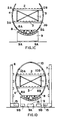
- FIGS. 1A to 1 D are views substantially in the direction of the arrow I in FIG. 2, illustrating a sequence of steps according to the invention in the assembly of a large structural component such as a jumbo aircraft fuselage having two floors and an oval cross-section;
- FIG. 2 is a side view of the present assembly station perpendicularly to the longitudinal or X-axis of the aircraft showing a plurality of assembled body sections;
- FIGS. 3A to 3 D show perspective, partly exploded views of the sequential assembly steps, whereby the assembly progresses from FIG. 3A to FIG. 3 D.
- FIG. 1A illustrates the first stage in which a central longitudinal assembly core 1 is secured with its far end to a mounting 12 forming part of a mounting column 12 A.
- the opposite end of the core 1 is held in place by a further mounting part 13 of a mounting column 13 A to be described below with reference to FIG. 2 .
- the central axis of the assembly core 1 extends in the direction of the central longitudinal axis of an aircraft fuselage not shown in FIG. 1 .
- the assembly core 1 has a rectangular cross-section.
- An upper floor grid 2 and a lower floor grid 3 are mechanically secured in a releasable manner by symbolically shown-clamping tools 16 driven by clamp drives 16 A which in turn are controlled by a computer 17 .
- a laser distance measuring system 18 is positioned for measuring any deviation of the core 1 from standard dimensions stored in the memory of the computer 17 .
- the clamping tools 16 are adjustable by the clamp drives 16 A in the Z-direction of the aircraft, namely up and down as indicated by the arrows 16 B.
- By adjusting the position of the clamps 16 in the Z-direction it is possible to compensate any shape and dimension variations in the central assembly core 1 , for example when the core 1 should be bent in the Z-direction between its two supported ends.
- the above-mentioned laser system 18 is conventional and capable of measuring the bending and/or dimensional deviations in a contactless manner.
- FIG. 1B shows a view similar to that of FIG. 1A, but now illustrating the second stage of assembly with the help of robot tool means 6 and 7 supported on carriages 6 A and 7 A movable in parallel to the longitudinal aircraft axis on rollers 6 B and 7 B.
- Each robot tool 6 and 7 carries respective tools 6 C, 7 C driven by individual drive elements 6 D and 7 D.
- Additional tools 6 E, 6 F, 6 G, 6 H and 7 E, 7 F, 7 G, 7 H are symbolically shown in FIG. 1B for holding and positioning wall shell sections 4 , 5 , 8 , 10 . All robot tools 6 , 7 and their individual tools are operated under the control of computers 15 .
- the drives for the carriages 6 A, 7 A are also computer controlled.
- the robot tools are of conventional construction and capable of holding, transporting and precisely positioning shell sections 4 and 5 which are side wall sections of the fuselage for connection to the floor grids 2 and 3 and bottom shells 8 as well as top shells 10 to the side wall sections ( 4 , 5 ).
- the side wall shell sections 4 and 5 are mechanically connected to the upper floor grid 2 at 2 A and 2 B and to the lower floor grid 3 at 3 A and 3 B.
- the elongated holding and positioning tools 6 C, 7 C shown in FIG. 1B are capable of holding a top shell section 10 shown in FIG. 1D to be described in more detail below. All operations are computer controlled.
- FIG. 1C shows the third assembly stage according to the present method in which a bottom wall shell section 8 transported by a robot carriage 9 with rollers 9 A driven by drives 9 B, is secured to the side wall sections 4 and 5 at 8 A and 8 B. All the connections between the subsections are conventional.
- the carriage 9 and its components are also part of the robot system which is controlled by programs stored in a memory of computers 15 .
- FIG. 1D shows the fourth stage of the present method in which an upper wall shell section 10 has been secured to the side sections 4 and 5 at 10 A and 10 B.
- the tools 6 C and 7 C of the robots 6 and 7 are capable of holding and positioning the top sections 10 relative to the side sections 4 and 5 .
- one body section BS of an aircraft body 14 see FIG. 2, is completed.
- the central assembly core 1 forms the basic component of the apparatus of the invention for the performance of the present method in the assembly of a large structural component, for example the fuselage of a jumbo aircraft.
- the assembly core 1 is equipped with elements E for supporting supply conduits such as electrical conductors, compressed air ducts for the operation of tools and power supplies for illuminating purposes as well as tool carriers.
- the assembly core 1 is preferably so constructed that it is capable to carry either one floor grid structure for a freight loading space or one floor grid structure for a passenger deck or the core 1 may carry two floor grids 2 and 3 for two passenger decks of a multi-deck jumbo aircraft fuselage 14 shown in FIG. 2 .
- the mounting columns 12 A and 13 A with their mountings 12 and 13 are so constructed that the central core 1 , once mounted, is accessible all around between the core ends, because the core 1 is mounted only at its ends so that the lateral bottom and top shell wall sections 4 , 5 and 8 , 10 can be mounted without any access problems.
- the maintaining of the proper curvature and of the correct positioning of the prefabricated wall shell sections 4 , 5 , 8 and 10 relative to the central core 1 is assured by the computer controlled robot system 6 , 7 and 9 , whereby the computers 15 and 17 control the holding, transporting and positioning of the wall shell sections.
- the alignment of the wall shell sections 4 , 5 and 8 , 10 to be connected to the shell sections 4 and 5 is accomplished with the aid of the contactless laser measuring system 18 that provides its information to the computers 15 and 17 which control all the tools drives.
- the tool drives 6 D and 7 D assure the proper positioning of the tools 6 C and 7 C and thus of the top shell section 10 .
- the finished product such as a jumbo aircraft body 14
- the finished product does satisfy the required high precision tolerances because the assembly of the individual sections already satisfies fine tolerances assured by the laser controlled positioning of the individual wall shell sections 4 , 5 , 8 and 10 .
- the wall sections 4 , 5 , 8 and 10 preassemble the wall sections 4 , 5 , 8 and 10 so that their outer contour curvature and geometry conform to the theoretically correct position within the shell of the whole body 14 relative to the zero axis of the system, for example relative to the central longitudinal axis of the assembly core 1 and of the aircraft body 14 .
- the correct curvature and geometry of the contour curvature of the shell wall sections 4 , 5 , 8 and 10 is already assured by the preassembly of these sections and the present assembly sequence maintains the correct curvature and geometry.
- the wall shell sections have an adequate inherent stiffness so that these sections will conform to the designed aircraft contour. More specifically, the inherent stiffness of the sections is sufficient if the sections do not change their outer contour during the assembly by the present computer controlled robot carrier and positioning system.
- the apparatus according to the invention shown in FIG. 2 in a side view includes the above-mentioned mounting 12 for example in the form of a clamping device 12 carried by column 12 A for holding one end of the assembly core 1 .
- the other end is mounted to the above-mentioned mounting 13 in the form of a clamping and guide column 13 A provided with a core clamping and guide mechanism 13 .
- the core clamping and guide mechanism 13 permits withdrawing the core 1 from the assembled fuselage or body 14 , which upon completion rests on supports 14 A and 14 B so that the core 1 may be withdrawn by the core clamping and guide mechanism 13 to the left in FIG. 2 .
- This clamping and guide mechanism 13 can position the core as indicated by the double arrow 13 B.
- the above described transporting holding and positioning robots 6 and 7 with their respective tools are part of the mounting station 11 . However, these robots 6 and 7 are not shown in FIG. 2 . These robots are movable alongside the core 1 of the station 11 shown in FIG. 2 as indicated by the double arrow 13 B to transport, hold and position the wall shell sections 4 , 5 , 8 and 10 as described above with references to FIGS. 1A to 1 D.
- the supports 14 A and 14 B are moved into position for the removal of the core 1 .
- the above described computer controlled clamping tools 16 , 16 A are released from the floor grids 2 and 3 , whereupon the core 1 can be moved to the left by the guide mechanism 13 .
- the clamping tools 16 are driven by their tool drive 16 A as indicated by the arrows 16 B to provide sufficient clearance between the tools that are mounted to the core 1 for holding or clamping the floor grids 2 and 3 .
- FIGS. 3A, 3 B, 3 C and 3 D also illustrate the sequence of assembly steps according to the invention, however, in a perspective illustration.
- FIG. 3A shows that the floor grids 2 and 3 have been secured to the assembly core 1 and the side wall shell sections 4 and 5 are ready for positioning and securing to the grids 2 and 3 .
- the robots, or rather the robot tools move the side wall sections 4 and 5 in the directions of the arrows A 1 and A 2 toward the grids 2 and 3 .
- FIG. 3B shows that the side wall sections 4 and 5 have been secured to the grids 2 and 3 .
- a top wall shell section 10 is moved into position for securing to the side wall sections 4 and 5 .
- a bottom wall shell section 8 is moved into position by the carriage 9 for attachment to the grids 2 and 3 .
- FIG. 3C shows that one fuselage or body section BS 1 is completed.
- the next fuselage section BS 2 has its side wall panel 4 ′ already secured to the grids 2 and 3 .
- the opposite side wall sections 5 ′ has also been secured to the grids 2 and 3 .
- the top wall shell section of the body section BS 2 differs from the top section 10 in that the second top wall shell section includes three components 10 A, 10 B and 10 C.
- the components 10 A and 10 B are connected to the respective side wall sections 4 ′ and 5 ′ whereupon, as shown in FIG. 3D the central top component 10 C is secured to the two other top components 10 A and 10 B.
- the bottom section 8 A is then positioned and secured to the lower edges of the side sections 4 ′ and 5 ′ as described, to form the second fuselage section FS 2 .
- the steps are then repeated for the formation of further body sections BS to form the fuselage.
- the sections are secured to each along a cross-seam CS shown in FIG. 3D, for example by riveting robot tools.
- the individual wall shell sections may be further divided into a plurality of components as shown for the top section 10 divided into three components 10 A, 10 B and 10 C.
Landscapes
- Engineering & Computer Science (AREA)
- Mechanical Engineering (AREA)
- Manufacturing & Machinery (AREA)
- Transportation (AREA)
- Aviation & Aerospace Engineering (AREA)
- Automatic Assembly (AREA)
- Moulding By Coating Moulds (AREA)
Abstract
Three-dimensional large scale bodies such as jumbo aircraft fuselages (14) are assembled in body sections around a central longitudinal assembly core (1) which itself is mounted at its ends and accessible all around along its length. Robots carrying tools for holding, transporting and precisely positioning pre-assembled wall shell sections, are movable along the central core (1). First, at least one floor grid (2 or 3) is releasably mounted to the core. Then, side wall shell sections (4, 5) are secured to the floor grids. Then, top and bottom wall shell sections (10, 8) are secured to the side wall shell sections (4, 5) to form a body section (BS) of the large scale body (14). Neighboring body sections are secured to each other along cross-seams. Upon completion, the floor grids are released from the core (1) and the core is removed preferably withdrawn longitudinally from the assembled large component or body.
Description
This application is a Divisional Application of U.S. application Ser. No. 09/603,870, filed Jun. 26, 2000 now U.S. Pat. No. 6,408,517.
This application is based on and claims the priority under 35 U.S.C. §119 of German Patent Application 199 29 471.2, filed on Jun. 26, 1999, the entire disclosure of which is incorporated herein by reference.
The invention relates to an apparatus for producing large three-dimensional structural components such as an aircraft fuselage or the like having an elongated barrel-shaped configuration or an oval or circular cross-section.
So-called large volume or jumbo aircraft have fuselages assembled from shell sections, preferably shell sections reinforced by load supporting elements such as stringers and spars or ribs. One or more plate-shaped floor grids are mounted inside such large scale fuselages. The floor grids extend longitudinally inside the fuselage and from one side wall to the opposite side wall.
German Patent Publication DE 34 38 584 A1 discloses an apparatus for the manufacture of an aircraft fuselage, whereby large surface area, curved structural elements are assembled to form fuselage sections. These fuselage sections are then interconnected by an automatically operating orbital riveting machine and by manual labor to form fuselage components. The riveting takes place along so-called cross-seams, whereby the automatic orbital riveting machine travels along these cross-seams guided by a machine guide rail extending as a ring around the aircraft body or fuselage. The entire orbital riveting machine or system is mounted on a carriage that can travel along or rather in parallel to the longitudinal aircraft axis also referred to as the X-axis.
In the manufacture of aircraft fuselages, it is further known to assemble subassemblies in rigid jigs that determine the geometry of the subassembly. Such rigid jigs operate on the principle of orienting all subassemblies relative to a zero position in a rigid system. According to such a known system, the preassembled subassemblies are deposited in jigs and located relative to fixed system points with a so-called zero alignment. Such a zero alignment system has the disadvantages that the zero alignment can result in deviations, particularly along the interface between individually neighboring subassemblies. Such deviations can fall outside permissible tolerance ranges. Moreover, an adjusting of the individual subassemblies in order to assure the desired overall geometry of the aircraft fuselage is not possible. However, as long as the fuselage has a circular cross-section that is a cylindrical configuration, the use of the zero alignment or positioning is possible, whereby the subassemblies forming the lower body half are positioned and riveted first whereupon the cabin floor is inserted and connected with the spars or ribs of the lower body half. A so-called auxiliary carrier, also referred to as a presenting frame, holds the subassembly relative to the jig and tool system in position without any possibility of making compensating adjustments in the positioning. Thus, positional deviations of the floor structure relative to the fuselage body are possible, but cannot be corrected. Once the floor structure and the lower fuselage half are assembled, the upper side wall shell sections and upper shell sections are secured to the lower half, whereby the positioning is again performed by way of the above-mentioned zero alignment.
Efforts have been made for avoiding some of the above described drawbacks. Thus, U.S. Pat. No. 5,694,690 (Micale) describes a method for producing large scale aircraft bodies from a plurality of subassemblies, whereby the subassemblies or selected components of the subassemblies are provided with drilled coordination holes for an accurate positioning and assembly of the subassemblies. The coordination holes make sure that the elements of the subassembly are already accurately positioned relative to each other so that the resulting subassemblies become self-locating and thus intrinsically determine the final contour of the aircraft body independently of tooling. The drilling of the coordination holes is accomplished by a computer controlled precision robot which is directed to the drilling locations using a digital data set taken directly from original digital part definition records.
The above described methods leave room for improvement, especially with regard to reducing the assembly costs while still assuring the required accuracy in the configuration of the final large scale product, such as a fuselage for a jumbo aircraft.
In view of the above it is the aim of the invention to achieve the following objects singly or in combination:
to provide an assembly apparatus for producing large scale components such as jumbo aircraft bodies, whereby the assembly permits maintaining required, precise tolerance ranges without the need for high precision jigs and without drilling precisely positioned locating holes, while still assuring the accuracy of the three-dimensional large scale body;
to substantially increase the accessibility of tools to the assembly positions for performing most assembly work by robots, particularly the forming of longitudinal and cross-seams; and
to provide a system and apparatus which substantially is independent of the length of the large scale body so that substantially any required number of subassemblies can be jointed to each other without any additional matching adjustments so that an entire aircraft fuselage can be assembled.
The above objects have been achieved by performing the following steps with the aid of the apparatus according to the invention. A prefabricated longitudinal central assembly core is mounted at its ends, for example between support columns. Then, at least one floor grid is secured to the assembly core with the aid of clamping tools which mechanically fasten the floor grid to the core. Then, shell-shaped sections having a defined internal stiffness of their own are positioned by robot tools which are preferably computer controlled, sequentially around the central assembly core and then mechanically interconnected, for example by riveting. The positioning is performed in such a way that first side wall shell sections are positioned opposite one another and secured to the floor grid or grids by mechanical means. Thereafter, bottom shell sections and top shell sections are sequentially secured to the side shells and to one another to form individual body sections of the large body such as a fuselage which is then completed by interconnecting individual body sections to each other, for example by riveting along cross-seams.
It is an important advantage of the invention that the assembly of the prefabricated shell sections or subsections can take place within a precise tolerance range, whereby, for example an aircraft fuselage section can be assembled with the required precision, yet without jigs or locating holes. All prefabricated subsections are positioned relative to the central prefabricated core which itself is lightweight and has its own stiffness. The core forms part of the assembly station and can be reused. The prefabricated fuselage planking is mounted to the floor grid or to the floor grids held in precise positions by the central longitudinal assembly core. By first mounting the side wall shell sections to the floor grid or grids, it becomes possible to mount or assemble the bottom fuselage shell section and the top shell section to the side shells without any difficulties. In a preferred form, the side wall shells are first secured to the floor grid or grids in a row, whereupon the upper and lower shells can also be secured in respective rows to the row of side wall shells.
According to a preferred embodiment of the present method, the three-dimensional large structural component is assembled of at least two body sections which are interconnected by the above-mentioned cross-seam, whereby each individual body section is so formed that the lateral or side shells are positioned opposite each other and are mechanically connected to the floor grid or grids to form a first subsection. Then the respective upper and/or lower shells are mechanically connected to the two side wall shells to form the first body section. Once the first body section is assembled the second section is assembled in the same manner and further sections are assembled next to the already assembled sections. Each body section is mechanically connected, e.g. by riveting, to the preceding body section along the cross-seams.
The apparatus according to the invention comprises a combination of the following features. An elongated central assembly core for holding at least one or more floor grids is secured with one end to a mounting held for example in a column, while the other end of the core is secured to a second mounting. Both mountings hold the core in a precise position relative to the longitudinal axis of a large scale body to be assembled. Tool means in the form of movable robots are provided for positioning body shell sections relative to the assembly core and relative to each other. A central processing unit is operatively connected to the tool means for controlling the tool means when they perform a holding, transporting and positioning operation for the assembly of shell sections relative to the floor grid or grids held by the core, whereupon additional tools perform the securing operations.
When the assembly is completed, the large scale body is supported by other supports, the central assembly core is released from the floor grids and removed from the body, for example by pulling the core longitudinally out of the body.
In order that the invention may be clearly understood, it will now be described in connection with example embodiments, with reference to the accompanying drawings, wherein:
FIGS. 1A to 1D are views substantially in the direction of the arrow I in FIG. 2, illustrating a sequence of steps according to the invention in the assembly of a large structural component such as a jumbo aircraft fuselage having two floors and an oval cross-section;
FIG. 2 is a side view of the present assembly station perpendicularly to the longitudinal or X-axis of the aircraft showing a plurality of assembled body sections; and
FIGS. 3A to 3D show perspective, partly exploded views of the sequential assembly steps, whereby the assembly progresses from FIG. 3A to FIG. 3D.
FIG. 1A illustrates the first stage in which a central longitudinal assembly core 1 is secured with its far end to a mounting 12 forming part of a mounting column 12A. The opposite end of the core 1 is held in place by a further mounting part 13 of a mounting column 13A to be described below with reference to FIG. 2. The central axis of the assembly core 1 extends in the direction of the central longitudinal axis of an aircraft fuselage not shown in FIG. 1. Preferably, the assembly core 1 has a rectangular cross-section. An upper floor grid 2 and a lower floor grid 3 are mechanically secured in a releasable manner by symbolically shown-clamping tools 16 driven by clamp drives 16A which in turn are controlled by a computer 17. A laser distance measuring system 18 is positioned for measuring any deviation of the core 1 from standard dimensions stored in the memory of the computer 17. The clamping tools 16 are adjustable by the clamp drives 16A in the Z-direction of the aircraft, namely up and down as indicated by the arrows 16B. By adjusting the position of the clamps 16 in the Z-direction, it is possible to compensate any shape and dimension variations in the central assembly core 1, for example when the core 1 should be bent in the Z-direction between its two supported ends. Thus, it is advantageously possible to compensate also for any dimensional deviations in the individual fuselage shell sections forming body sections of the fuselage. The above-mentioned laser system 18 is conventional and capable of measuring the bending and/or dimensional deviations in a contactless manner.
FIG. 1B shows a view similar to that of FIG. 1A, but now illustrating the second stage of assembly with the help of robot tool means 6 and 7 supported on carriages 6A and 7A movable in parallel to the longitudinal aircraft axis on rollers 6B and 7B. Each robot tool 6 and 7 carries respective tools 6C, 7C driven by individual drive elements 6D and 7D. Additional tools 6E, 6F, 6G, 6H and 7E, 7F, 7G, 7H are symbolically shown in FIG. 1B for holding and positioning wall shell sections 4, 5, 8, 10. All robot tools 6, 7 and their individual tools are operated under the control of computers 15. The drives for the carriages 6A, 7A are also computer controlled. The robot tools are of conventional construction and capable of holding, transporting and precisely positioning shell sections 4 and 5 which are side wall sections of the fuselage for connection to the floor grids 2 and 3 and bottom shells 8 as well as top shells 10 to the side wall sections (4, 5). As shown in FIG. 1B, the side wall shell sections 4 and 5 are mechanically connected to the upper floor grid 2 at 2A and 2B and to the lower floor grid 3 at 3A and 3B. The elongated holding and positioning tools 6C, 7C shown in FIG. 1B are capable of holding a top shell section 10 shown in FIG. 1D to be described in more detail below. All operations are computer controlled.
FIG. 1C shows the third assembly stage according to the present method in which a bottom wall shell section 8 transported by a robot carriage 9 with rollers 9A driven by drives 9B, is secured to the side wall sections 4 and 5 at 8A and 8B. All the connections between the subsections are conventional. The carriage 9 and its components are also part of the robot system which is controlled by programs stored in a memory of computers 15.
FIG. 1D shows the fourth stage of the present method in which an upper wall shell section 10 has been secured to the side sections 4 and 5 at 10A and 10B. As mentioned, the tools 6C and 7C of the robots 6 and 7 are capable of holding and positioning the top sections 10 relative to the side sections 4 and 5. With the completion of the fourth assembly stage one body section BS of an aircraft body 14, see FIG. 2, is completed.
Referring to FIG. 2 the central assembly core 1 forms the basic component of the apparatus of the invention for the performance of the present method in the assembly of a large structural component, for example the fuselage of a jumbo aircraft. The assembly core 1 is equipped with elements E for supporting supply conduits such as electrical conductors, compressed air ducts for the operation of tools and power supplies for illuminating purposes as well as tool carriers. The assembly core 1 is preferably so constructed that it is capable to carry either one floor grid structure for a freight loading space or one floor grid structure for a passenger deck or the core 1 may carry two floor grids 2 and 3 for two passenger decks of a multi-deck jumbo aircraft fuselage 14 shown in FIG. 2.
The mounting columns 12A and 13A with their mountings 12 and 13 are so constructed that the central core 1, once mounted, is accessible all around between the core ends, because the core 1 is mounted only at its ends so that the lateral bottom and top shell wall sections 4, 5 and 8, 10 can be mounted without any access problems. The maintaining of the proper curvature and of the correct positioning of the prefabricated wall shell sections 4, 5, 8 and 10 relative to the central core 1 is assured by the computer controlled robot system 6, 7 and 9, whereby the computers 15 and 17 control the holding, transporting and positioning of the wall shell sections. The alignment of the wall shell sections 4, 5 and 8, 10 to be connected to the shell sections 4 and 5 is accomplished with the aid of the contactless laser measuring system 18 that provides its information to the computers 15 and 17 which control all the tools drives. For example, the tool drives 6D and 7D assure the proper positioning of the tools 6C and 7C and thus of the top shell section 10. The same applies to the positioning of the carriage 9 with the bottom section 8 and to the other tools 6E to 6H and 7E to 7H and their respective drives.
The most important advantage of the present system is seen in that the finished product, such as a jumbo aircraft body 14, does satisfy the required high precision tolerances because the assembly of the individual sections already satisfies fine tolerances assured by the laser controlled positioning of the individual wall shell sections 4, 5, 8 and 10.
It is also advantageous to preassemble the wall sections 4, 5, 8 and 10 so that their outer contour curvature and geometry conform to the theoretically correct position within the shell of the whole body 14 relative to the zero axis of the system, for example relative to the central longitudinal axis of the assembly core 1 and of the aircraft body 14. The correct curvature and geometry of the contour curvature of the shell wall sections 4, 5, 8 and 10 is already assured by the preassembly of these sections and the present assembly sequence maintains the correct curvature and geometry. Further, the wall shell sections have an adequate inherent stiffness so that these sections will conform to the designed aircraft contour. More specifically, the inherent stiffness of the sections is sufficient if the sections do not change their outer contour during the assembly by the present computer controlled robot carrier and positioning system.
The apparatus according to the invention shown in FIG. 2 in a side view includes the above-mentioned mounting 12 for example in the form of a clamping device 12 carried by column 12A for holding one end of the assembly core 1. The other end is mounted to the above-mentioned mounting 13 in the form of a clamping and guide column 13A provided with a core clamping and guide mechanism 13. The core clamping and guide mechanism 13 permits withdrawing the core 1 from the assembled fuselage or body 14, which upon completion rests on supports 14A and 14B so that the core 1 may be withdrawn by the core clamping and guide mechanism 13 to the left in FIG. 2. This clamping and guide mechanism 13 can position the core as indicated by the double arrow 13B. The above described transporting holding and positioning robots 6 and 7 with their respective tools are part of the mounting station 11. However, these robots 6 and 7 are not shown in FIG. 2. These robots are movable alongside the core 1 of the station 11 shown in FIG. 2 as indicated by the double arrow 13B to transport, hold and position the wall shell sections 4, 5, 8 and 10 as described above with references to FIGS. 1A to 1D.
As soon as the fuselage 14 is completed the supports 14A and 14B are moved into position for the removal of the core 1. Prior to the removal, the above described computer controlled clamping tools 16, 16A are released from the floor grids 2 and 3, whereupon the core 1 can be moved to the left by the guide mechanism 13. For this purpose it is advantageous if the clamping tools 16 are driven by their tool drive 16A as indicated by the arrows 16B to provide sufficient clearance between the tools that are mounted to the core 1 for holding or clamping the floor grids 2 and 3.
FIGS. 3A, 3B, 3C and 3D also illustrate the sequence of assembly steps according to the invention, however, in a perspective illustration.
FIG. 3A shows that the floor grids 2 and 3 have been secured to the assembly core 1 and the side wall shell sections 4 and 5 are ready for positioning and securing to the grids 2 and 3. For this purpose the robots, or rather the robot tools move the side wall sections 4 and 5 in the directions of the arrows A1 and A2 toward the grids 2 and 3.
FIG. 3B shows that the side wall sections 4 and 5 have been secured to the grids 2 and 3. Next, a top wall shell section 10 is moved into position for securing to the side wall sections 4 and 5. Next, a bottom wall shell section 8 is moved into position by the carriage 9 for attachment to the grids 2 and 3.
FIG. 3C shows that one fuselage or body section BS1 is completed. The next fuselage section BS2 has its side wall panel 4′ already secured to the grids 2 and 3. The opposite side wall sections 5′ has also been secured to the grids 2 and 3. The top wall shell section of the body section BS2 differs from the top section 10 in that the second top wall shell section includes three components 10A, 10B and 10C. The components 10A and 10B are connected to the respective side wall sections 4′ and 5′ whereupon, as shown in FIG. 3D the central top component 10C is secured to the two other top components 10A and 10B. The bottom section 8A is then positioned and secured to the lower edges of the side sections 4′ and 5′ as described, to form the second fuselage section FS2. The steps are then repeated for the formation of further body sections BS to form the fuselage.
Once the two body sections BS1 and BS2 are assembled as described, the sections are secured to each along a cross-seam CS shown in FIG. 3D, for example by riveting robot tools. From the just described assembly of the fuselage section BS2 it is clear, that the individual wall shell sections may be further divided into a plurality of components as shown for the top section 10 divided into three components 10A, 10B and 10C.
Although the invention has been described with reference to specific example embodiments, it will be appreciated that it is intended to cover all modifications and equivalents within the scope of the appended claims. It should also be understood that the present disclosure includes all possible combinations of any individual features recited in any of the appended claims.
Claims (7)
1. An apparatus for assembling at least one body section (BS) of a structural component (14) including a plurality of wall shell sections (4, 5, 8, 10) and at least one floor grid (2 or 3), said apparatus comprising: an elongated central assembly core (1) for holding at least one said floor grid, a first mounting (12) for holding one end of said elongated central assembly core (1) outside said at least one body section, a second mounting (13) for holding an opposite end of said elongated central assembly core (1) outside said at least one body section, tool means (6, 7, 9, 16) for holding, transporting and positioning said wall shell sections relative to said elongated central assembly core (1) and relative to each other, at least one central processing unit (15, 17) operatively connected to said tool means (6, 7, 9, 16) for controlling said tool means, and wherein said first and second mountings outside said at least one body section provide access for said tool means to said at least one body section for forming longitudinal seams and cross seams in said at least one body section.
2. The apparatus of claim 1 , wherein said tool means comprise first and second carriages (6, 7) for movement alongside said assembly core, each of said carriages comprising tools (6C, 7C . . . ) for holding said wall shell sections (4, 5), drives (6D, 7D . . . ) for operating said tools for holding, transporting and positioning said wall shell sections (4, 5).
3. The apparatus of claim 2 , wherein said tools comprise holding element extensions for holding top wall shell sections (10).
4. The apparatus of claim 2 , further comprising a third carriage (9) for transporting and positioning bottom wall shell sections (8) of said body section, and drive means (9A, 9B) for moving said third carriage (9) longitudinally in parallel to said elongated assembly core (1).
5. The apparatus of claim 1 , wherein said elongated assembly core (1) comprises clamping elements (16) for releasably securing said at least one floor grid (2, 3) to said elongated assembly core, clamp drive means (16A) for operating said clamping elements and a computer (17) for controlling through said clamp drive means (16A) an operation of said clamping elements (16).
6. The apparatus of claim 5 , further comprising a laser system (18) for measuring positional deviations of said elongated assembly core (1) and of dimensional deviations of said sections (4, 5) for producing respective input signals for said computer (17) which provides control signals for said clamp drives to compensate said positional deviations and said dimensional deviations by respectively adjusting said clamps.
7. The apparatus of claim 1 , wherein said elongated assembly core (1) comprises elements (E) for carrying any one of supply conduits, electrical conductors, illumination devices, and tool supports.
Priority Applications (1)
| Application Number | Priority Date | Filing Date | Title |
|---|---|---|---|
| US09/919,388 US6481096B2 (en) | 1999-06-26 | 2001-07-31 | Apparatus for assembling a three-dimensional structural component |
Applications Claiming Priority (5)
| Application Number | Priority Date | Filing Date | Title |
|---|---|---|---|
| DE19929471.2 | 1999-06-26 | ||
| DE19929471A DE19929471C1 (en) | 1999-06-26 | 1999-06-26 | Method and device for producing a three-dimensional large component |
| DE19929471 | 1999-06-26 | ||
| US09/603,870 US6408517B1 (en) | 1999-06-26 | 2000-06-26 | Method and apparatus for assembling a three-dimensional structural component |
| US09/919,388 US6481096B2 (en) | 1999-06-26 | 2001-07-31 | Apparatus for assembling a three-dimensional structural component |
Related Parent Applications (1)
| Application Number | Title | Priority Date | Filing Date |
|---|---|---|---|
| US09/603,870 Division US6408517B1 (en) | 1999-06-26 | 2000-06-26 | Method and apparatus for assembling a three-dimensional structural component |
Publications (2)
| Publication Number | Publication Date |
|---|---|
| US20010054228A1 US20010054228A1 (en) | 2001-12-27 |
| US6481096B2 true US6481096B2 (en) | 2002-11-19 |
Family
ID=7912756
Family Applications (2)
| Application Number | Title | Priority Date | Filing Date |
|---|---|---|---|
| US09/603,870 Expired - Lifetime US6408517B1 (en) | 1999-06-26 | 2000-06-26 | Method and apparatus for assembling a three-dimensional structural component |
| US09/919,388 Expired - Lifetime US6481096B2 (en) | 1999-06-26 | 2001-07-31 | Apparatus for assembling a three-dimensional structural component |
Family Applications Before (1)
| Application Number | Title | Priority Date | Filing Date |
|---|---|---|---|
| US09/603,870 Expired - Lifetime US6408517B1 (en) | 1999-06-26 | 2000-06-26 | Method and apparatus for assembling a three-dimensional structural component |
Country Status (4)
| Country | Link |
|---|---|
| US (2) | US6408517B1 (en) |
| EP (1) | EP1063166B1 (en) |
| DE (2) | DE19929471C1 (en) |
| ES (1) | ES2194645T3 (en) |
Cited By (22)
| Publication number | Priority date | Publication date | Assignee | Title |
|---|---|---|---|---|
| US6691392B2 (en) * | 2001-05-16 | 2004-02-17 | Utica Enterprises, Inc. | Method and apparatus for assembling exterior automotive vehicle body components onto an automotive vehicle body |
| US20060277751A1 (en) * | 2005-05-09 | 2006-12-14 | The Boeing Company | Rotating internal support apparatus and method for large hollow structures |
| US20060284047A1 (en) * | 2005-06-16 | 2006-12-21 | The Boeing Company | Rotating internal support apparatus and method for large hollow structures |
| US20070107366A1 (en) * | 2005-10-14 | 2007-05-17 | Enrique Franco | Apparatus and method for manufacturing poles and columns |
| US20100192377A1 (en) * | 2007-09-18 | 2010-08-05 | Andreas Stephan | Method for producing a fuselage airframe of an aircraft |
| US20130019446A1 (en) * | 2011-07-21 | 2013-01-24 | Spirit Aerosystems, Inc. | System and method for assembling aircraft components |
| CN102950458A (en) * | 2011-08-24 | 2013-03-06 | 上海福伊特水电设备有限公司 | Three-dimensional positioning and assembly tool for mixed-flow runner blades |
| CN103158890A (en) * | 2011-12-15 | 2013-06-19 | 波音公司 | Automated assembly of panelized aircraft fuselages |
| US20140259596A1 (en) * | 2013-03-15 | 2014-09-18 | The Boeing Company | Condition of Assembly Visualization System Based On Build Cycles |
| US9292180B2 (en) | 2013-02-28 | 2016-03-22 | The Boeing Company | Locator system for three-dimensional visualization |
| US9340304B2 (en) | 2013-02-28 | 2016-05-17 | The Boeing Company | Aircraft comparison system |
| US9505051B2 (en) | 2014-07-09 | 2016-11-29 | The Boeing Company | Mobile platforms for performing operations along an exterior of a fuselage assembly |
| US9612725B1 (en) | 2013-02-28 | 2017-04-04 | The Boeing Company | Nonconformance visualization system |
| US9870444B2 (en) | 2013-03-05 | 2018-01-16 | The Boeing Company | Shop order status visualization system |
| US9880694B2 (en) | 2013-05-09 | 2018-01-30 | The Boeing Company | Shop order status visualization system |
| US10061481B2 (en) | 2013-02-28 | 2018-08-28 | The Boeing Company | Methods and devices for visually querying an aircraft based on an area of an image |
| US10067650B2 (en) | 2013-06-20 | 2018-09-04 | The Boeing Company | Aircraft comparison system with synchronized displays |
| US10331295B2 (en) | 2013-03-28 | 2019-06-25 | The Boeing Company | Visualization of an object using a visual query system |
| US10416857B2 (en) | 2013-05-09 | 2019-09-17 | The Boeing Company | Serial number control visualization system |
| US10481768B2 (en) | 2013-04-12 | 2019-11-19 | The Boeing Company | Nonconformance identification and visualization system and method |
| US10685147B2 (en) | 2016-02-29 | 2020-06-16 | The Boeing Company | Non-conformance mapping and visualization |
| US11267585B2 (en) * | 2018-09-25 | 2022-03-08 | Airbus Operations Sas | Method for assembling an aircraft fuselage section from two superposed upper and lower parts, multipurpose mounting support, gear and fuselage section production unit for implementing said method |
Families Citing this family (49)
| Publication number | Priority date | Publication date | Assignee | Title |
|---|---|---|---|---|
| FR2821778B1 (en) * | 2001-03-07 | 2004-11-19 | S O C O A Soc De Conception Co | METHOD FOR THE AUTOMATED ASSEMBLY OF LARGE STRUCTURES, PARTICULARLY AERONAUTICS, DEVICES AND SOFTWARE PRODUCT FOR IMPLEMENTING THE SAME |
| DE10146442B4 (en) * | 2001-09-20 | 2005-01-27 | Thyssenkrupp Automotive Ag | Device for connecting two or more components by means of rivets |
| FR2863673B1 (en) * | 2003-12-10 | 2006-03-10 | Airbus France | DEVICE FOR ASSEMBLING BY SEPARATING MULTIPLE ELEMENTS AND METHOD FOR ASSEMBLING PANELS, IN PARTICULAR AIRCRAFT FUSELAGE USING THE SAME |
| US20060010689A1 (en) * | 2004-07-14 | 2006-01-19 | Ali Salour | Automated drill process for two-diameter holes in multi-layer variable thickness composite materials |
| FR2877916B1 (en) * | 2004-11-15 | 2008-04-25 | Airbus France Sas | AIRCRAFT FUSELAGE STRUCTURE FRAME |
| US20060185143A1 (en) * | 2004-11-22 | 2006-08-24 | Airbus Deutschland Gmbh | Method and device for manufacturing sections for transportation systems |
| DE102004056286B4 (en) | 2004-11-22 | 2015-12-24 | Airbus Operations Gmbh | Device and method for shape and / or dimension independent assembly and stitching of several individual components to form intrinsically rigid, transportable sections for transport, especially for aircraft |
| DE102004056285B4 (en) * | 2004-11-22 | 2010-08-26 | Airbus Deutschland Gmbh | Device with at least two articulated robots for form and / or dimension independent connection of individual components to form sections for aircraft |
| DE102004056287A1 (en) * | 2004-11-22 | 2006-05-24 | Airbus Deutschland Gmbh | Apparatus and method for producing sections for means of transport, in particular for aircraft |
| DE102004056284B4 (en) * | 2004-11-22 | 2010-08-26 | Airbus Deutschland Gmbh | Device for transporting components for transport |
| US7850374B2 (en) * | 2005-01-14 | 2010-12-14 | Avago Technologies Fiber Ip (Singapore) Pte. Ltd. | Optical transmitter module with an integrated lens and method for making the module |
| DE102005054869A1 (en) * | 2005-11-17 | 2007-05-31 | Airbus Deutschland Gmbh | Method for producing a fuselage cell of an aircraft |
| DE102006015642B4 (en) * | 2006-03-29 | 2009-12-31 | Ima Materialforschung Und Anwendungstechnik Gmbh | Testing device for hull shells |
| DE102006025930B4 (en) * | 2006-06-02 | 2008-09-11 | Airbus Deutschland Gmbh | Hull structure and method of making a hull structure |
| CN101472794B (en) | 2006-06-28 | 2013-03-13 | 空中客车德国运营有限责任公司 | Aerial vehicle airframe segment, aerial vehicle airframe and method for producing aerial vehicle airframe |
| DE102006060360B8 (en) * | 2006-12-20 | 2010-09-30 | Airbus Deutschland Gmbh | Fuselage section to form a fuselage cell of an aircraft |
| US7849729B2 (en) | 2006-12-22 | 2010-12-14 | The Boeing Company | Leak detection in vacuum bags |
| CN100491202C (en) * | 2007-04-12 | 2009-05-27 | 沈阳飞机工业(集团)有限公司 | Method for digitally assembling spatial composite angle positioner tool |
| US8568551B2 (en) * | 2007-05-22 | 2013-10-29 | The Boeing Company | Pre-patterned layup kit and method of manufacture |
| US9770871B2 (en) | 2007-05-22 | 2017-09-26 | The Boeing Company | Method and apparatus for layup placement |
| DE102007028918A1 (en) * | 2007-06-22 | 2009-01-02 | Airbus Deutschland Gmbh | Method for producing a fuselage cell of an aircraft and device |
| US8707766B2 (en) | 2010-04-21 | 2014-04-29 | The Boeing Company | Leak detection in vacuum bags |
| US8333864B2 (en) | 2008-09-30 | 2012-12-18 | The Boeing Company | Compaction of prepreg plies on composite laminate structures |
| US8936695B2 (en) | 2007-07-28 | 2015-01-20 | The Boeing Company | Method for forming and applying composite layups having complex geometries |
| US8752293B2 (en) | 2007-12-07 | 2014-06-17 | The Boeing Company | Method of fabricating structures using composite modules and structures made thereby |
| US8916010B2 (en) | 2007-12-07 | 2014-12-23 | The Boeing Company | Composite manufacturing method |
| US8468674B2 (en) * | 2008-12-02 | 2013-06-25 | Airbus Operations Gmbh | Device and method for supplying structural components to an assembly zone |
| DE102008044262B4 (en) | 2008-12-02 | 2019-12-12 | Airbus Operations Gmbh | Apparatus and method for clocking structural components into a building site |
| ES2376098B1 (en) | 2009-07-24 | 2013-02-04 | Airbus Operations S.L. | PROCESS OF ASSEMBLY OF FUSELAGE SECTIONS OF AN AIRCRAFT. |
| DE102011005632B4 (en) * | 2011-03-16 | 2013-09-19 | Siemens Aktiengesellschaft | Build-up state for assembly of car body assemblies |
| CN102794728B (en) * | 2012-08-22 | 2014-07-02 | 浙江大学 | Ball head self-adaption positioning and locking device and method thereof |
| US9604319B2 (en) | 2013-08-13 | 2017-03-28 | The Boeing Company | Method for processing curved sheets using magnetic clamping members |
| DE102013110684A1 (en) * | 2013-09-26 | 2015-03-26 | Airbus Operations Gmbh | Method for assembling an aircraft fuselage and hull production station |
| FR3020347B1 (en) * | 2014-04-28 | 2016-05-20 | Airbus Operations Sas | METHOD FOR ASSEMBLING A REAR AIRCRAFT PART |
| EP2985232A1 (en) * | 2014-08-13 | 2016-02-17 | Airbus Operations GmbH | Method for assembling an aircraft fuselage |
| US9555587B2 (en) * | 2014-08-13 | 2017-01-31 | The Boeing Company | Composite layup tools for aircraft fuselage barrels, methods of assembling the layup tools, and aircraft fuselage barrel sections formed utilizing the layup tools |
| DE102014111747B4 (en) * | 2014-08-18 | 2021-11-04 | Airbus Operations Gmbh | Processing device for the assembly of aircraft |
| DE102014116560A1 (en) * | 2014-11-12 | 2016-05-12 | Airbus Operations Gmbh | A method and apparatus for securing an aircraft or spacecraft component to a fuselage section of an aircraft or spacecraft |
| JP6523693B2 (en) | 2015-01-28 | 2019-06-05 | 三菱重工業株式会社 | Aircraft component positioning device, aircraft assembly system and aircraft assembly method |
| FR3035075B1 (en) * | 2015-04-20 | 2018-08-17 | Airbus Operations | TOOLING ASSEMBLY FOR INTEGRATION OF A CENTRAL AIRCRAFT PART, ASSOCIATED METHOD AND AIRCRAFT SO INTEGRATED |
| JP6563271B2 (en) * | 2015-08-03 | 2019-08-21 | 三菱重工業株式会社 | Assembly manufacturing apparatus and assembly manufacturing method |
| JP6629001B2 (en) | 2015-08-03 | 2020-01-15 | 三菱重工業株式会社 | Assembly manufacturing apparatus and assembly manufacturing method |
| CN105539876B (en) * | 2015-12-14 | 2018-12-18 | 浙江日发航空数字装备有限责任公司 | Aircraft assembly posture adjustment ball head device |
| JP6650147B2 (en) * | 2016-02-02 | 2020-02-19 | 三菱重工業株式会社 | Aircraft panel manufacturing method and aircraft panel manufacturing system |
| FR3072656B1 (en) * | 2017-10-24 | 2019-11-08 | Airbus | TOOLING SYSTEM FOR THE HANDLING OF AT LEAST ONE UPPER MODULE AND / OR AT LEAST ONE LOWER MODULE. |
| CN114056595B (en) * | 2020-08-04 | 2024-01-23 | 上海飞机制造有限公司 | Numerical control locator stress release device and docking attitude adjustment system |
| JP2022080864A (en) * | 2020-11-18 | 2022-05-30 | ザ・ボーイング・カンパニー | Composite assembly for unhardened fuselage components |
| EP4311782A1 (en) * | 2022-07-25 | 2024-01-31 | Airbus Operations SAS | System for handling a side shell of an aircraft for an assembly of a fuselage body of the aircraft and method for assembling a fuselage body of an aircraft |
| FR3138122A1 (en) * | 2022-07-25 | 2024-01-26 | Airbus Operations | Aircraft cabin floor grid transport system for assembling an aircraft fuselage body and method of calibrating said transport system. |
Citations (14)
| Publication number | Priority date | Publication date | Assignee | Title |
|---|---|---|---|---|
| US2117435A (en) * | 1937-05-20 | 1938-05-17 | Clifford B Langstroth | Machine for use in manufacturing boiler shells |
| US2378043A (en) * | 1942-10-24 | 1945-06-12 | Ford Motor Co | Method of airframe assembly |
| US2594586A (en) * | 1948-11-15 | 1952-04-29 | Edo Corp | Shipping container |
| US2928535A (en) * | 1953-07-14 | 1960-03-15 | Walter A Simmons | Shock-resisting support for storing and shipping engines and the like equipment containing destructible components |
| US3194525A (en) * | 1964-02-07 | 1965-07-13 | James E Webb | Supporting and protecting device |
| US3612484A (en) * | 1969-01-06 | 1971-10-12 | Nat Steel Erecting Corp | Apparatus for lifting and transporting disabled aircraft |
| US4259776A (en) | 1978-08-09 | 1981-04-07 | Airships International Inc. | Method of assembly of airship hull |
| US4462535A (en) * | 1981-04-23 | 1984-07-31 | Amca International Corporation | Apparatus and process for manufacture of tunnel tubes |
| DE3438584A1 (en) | 1983-10-21 | 1985-05-23 | Atlas Copco AB, Nacka | DEVICE FOR RIVETING TWO OR MORE SHEETS OF A SHEET STRUCTURE |
| FR2702982A1 (en) | 1993-03-23 | 1994-09-30 | Aerospatiale | Device for positioning a tool support or the like on the outer face of a tubular structure, especially an aircraft fuselage |
| US5645389A (en) * | 1995-11-30 | 1997-07-08 | Stanley Aviation Corporation | Shipping frame from fan section of aircraft engine |
| US5694690A (en) | 1992-10-13 | 1997-12-09 | The Boeing Company | Method of making large airplane structures |
| FR2788743A1 (en) | 1999-01-22 | 2000-07-28 | Torres Ingenieria De Procesos | Assembly jig for aircraft fuselage sections has frame with mountings to support fuselage halves and components for assembly |
| US6170141B1 (en) * | 1998-09-25 | 2001-01-09 | Stanley Aviation Corporation | Shipping system for jet aircraft engine and method of installing and removing jet aircraft engine |
Family Cites Families (5)
| Publication number | Priority date | Publication date | Assignee | Title |
|---|---|---|---|---|
| US2370083A (en) * | 1942-04-13 | 1945-02-20 | Cons Aircraft Corp | Method of assembling airplane fuselages and the like |
| US2374894A (en) * | 1943-06-16 | 1945-05-01 | Ford Motor Co | Method and apparatus for assembling aircraft fuselages |
| US2391510A (en) * | 1944-05-13 | 1945-12-25 | Ford Motor Co | Mating fixture |
| US4371108A (en) * | 1980-08-09 | 1983-02-01 | Stephen Roggendorff | Methods of manufacturing large tubular columns |
| US6230382B1 (en) * | 1998-05-11 | 2001-05-15 | Vought Aircraft Industries, Inc. | System and method for assembling an aircraft |
-
1999
- 1999-06-26 DE DE19929471A patent/DE19929471C1/en not_active Expired - Fee Related
-
2000
- 2000-05-31 ES ES00111628T patent/ES2194645T3/en not_active Expired - Lifetime
- 2000-05-31 DE DE50001766T patent/DE50001766D1/en not_active Expired - Lifetime
- 2000-05-31 EP EP00111628A patent/EP1063166B1/en not_active Expired - Lifetime
- 2000-06-26 US US09/603,870 patent/US6408517B1/en not_active Expired - Lifetime
-
2001
- 2001-07-31 US US09/919,388 patent/US6481096B2/en not_active Expired - Lifetime
Patent Citations (15)
| Publication number | Priority date | Publication date | Assignee | Title |
|---|---|---|---|---|
| US2117435A (en) * | 1937-05-20 | 1938-05-17 | Clifford B Langstroth | Machine for use in manufacturing boiler shells |
| US2378043A (en) * | 1942-10-24 | 1945-06-12 | Ford Motor Co | Method of airframe assembly |
| US2594586A (en) * | 1948-11-15 | 1952-04-29 | Edo Corp | Shipping container |
| US2928535A (en) * | 1953-07-14 | 1960-03-15 | Walter A Simmons | Shock-resisting support for storing and shipping engines and the like equipment containing destructible components |
| US3194525A (en) * | 1964-02-07 | 1965-07-13 | James E Webb | Supporting and protecting device |
| US3612484A (en) * | 1969-01-06 | 1971-10-12 | Nat Steel Erecting Corp | Apparatus for lifting and transporting disabled aircraft |
| US4259776A (en) | 1978-08-09 | 1981-04-07 | Airships International Inc. | Method of assembly of airship hull |
| US4462535A (en) * | 1981-04-23 | 1984-07-31 | Amca International Corporation | Apparatus and process for manufacture of tunnel tubes |
| DE3438584A1 (en) | 1983-10-21 | 1985-05-23 | Atlas Copco AB, Nacka | DEVICE FOR RIVETING TWO OR MORE SHEETS OF A SHEET STRUCTURE |
| US4662556A (en) * | 1983-10-21 | 1987-05-05 | Atlas Copco Aktiebolag | Device for assembling by riveting two or more sections of a structure |
| US5694690A (en) | 1992-10-13 | 1997-12-09 | The Boeing Company | Method of making large airplane structures |
| FR2702982A1 (en) | 1993-03-23 | 1994-09-30 | Aerospatiale | Device for positioning a tool support or the like on the outer face of a tubular structure, especially an aircraft fuselage |
| US5645389A (en) * | 1995-11-30 | 1997-07-08 | Stanley Aviation Corporation | Shipping frame from fan section of aircraft engine |
| US6170141B1 (en) * | 1998-09-25 | 2001-01-09 | Stanley Aviation Corporation | Shipping system for jet aircraft engine and method of installing and removing jet aircraft engine |
| FR2788743A1 (en) | 1999-01-22 | 2000-07-28 | Torres Ingenieria De Procesos | Assembly jig for aircraft fuselage sections has frame with mountings to support fuselage halves and components for assembly |
Cited By (54)
| Publication number | Priority date | Publication date | Assignee | Title |
|---|---|---|---|---|
| US6691392B2 (en) * | 2001-05-16 | 2004-02-17 | Utica Enterprises, Inc. | Method and apparatus for assembling exterior automotive vehicle body components onto an automotive vehicle body |
| US20060277751A1 (en) * | 2005-05-09 | 2006-12-14 | The Boeing Company | Rotating internal support apparatus and method for large hollow structures |
| US20060284047A1 (en) * | 2005-06-16 | 2006-12-21 | The Boeing Company | Rotating internal support apparatus and method for large hollow structures |
| US7596843B2 (en) | 2005-06-16 | 2009-10-06 | The Boeing Company | Rotating internal support apparatus and method for large hollow structures |
| US20070107366A1 (en) * | 2005-10-14 | 2007-05-17 | Enrique Franco | Apparatus and method for manufacturing poles and columns |
| US7926694B2 (en) * | 2005-10-14 | 2011-04-19 | Enrique Franco | Apparatus for vertically manufacturing poles and columns |
| US20100192377A1 (en) * | 2007-09-18 | 2010-08-05 | Andreas Stephan | Method for producing a fuselage airframe of an aircraft |
| US8302312B2 (en) | 2007-09-18 | 2012-11-06 | Airbus Operations Gmbh | Method for producing a fuselage airframe of an aircraft |
| RU2466058C2 (en) * | 2007-09-18 | 2012-11-10 | Эйрбас Оперейшнз Гмбх | Method of producing aircraft fuselage |
| US8914979B2 (en) * | 2011-07-21 | 2014-12-23 | Spirit AcroSystems, Inc. | System and method for assembling aircraft components |
| US20130019446A1 (en) * | 2011-07-21 | 2013-01-24 | Spirit Aerosystems, Inc. | System and method for assembling aircraft components |
| CN102950458A (en) * | 2011-08-24 | 2013-03-06 | 上海福伊特水电设备有限公司 | Three-dimensional positioning and assembly tool for mixed-flow runner blades |
| US20130152397A1 (en) * | 2011-12-15 | 2013-06-20 | The Boeing Company | Automated assembly of panelized aircraft fuselages |
| CN103158890A (en) * | 2011-12-15 | 2013-06-19 | 波音公司 | Automated assembly of panelized aircraft fuselages |
| US9090357B2 (en) * | 2011-12-15 | 2015-07-28 | The Boeing Company | Method of assembling panelized aircraft fuselages |
| US9205933B2 (en) * | 2011-12-15 | 2015-12-08 | The Boeing Company | Automated assembly of panelized aircraft fuselages |
| CN103158890B (en) * | 2011-12-15 | 2016-09-14 | 波音公司 | The automatic assembling of jigsaw airframe |
| CN106114906A (en) * | 2011-12-15 | 2016-11-16 | 波音公司 | The automatic assembling of jigsaw airframe |
| JP2017206247A (en) * | 2011-12-15 | 2017-11-24 | ザ・ボーイング・カンパニーThe Boeing Company | Automated assembly of panelized aircraft fuselages |
| US10061481B2 (en) | 2013-02-28 | 2018-08-28 | The Boeing Company | Methods and devices for visually querying an aircraft based on an area of an image |
| US9292180B2 (en) | 2013-02-28 | 2016-03-22 | The Boeing Company | Locator system for three-dimensional visualization |
| US9340304B2 (en) | 2013-02-28 | 2016-05-17 | The Boeing Company | Aircraft comparison system |
| US9612725B1 (en) | 2013-02-28 | 2017-04-04 | The Boeing Company | Nonconformance visualization system |
| US9870444B2 (en) | 2013-03-05 | 2018-01-16 | The Boeing Company | Shop order status visualization system |
| US20140259596A1 (en) * | 2013-03-15 | 2014-09-18 | The Boeing Company | Condition of Assembly Visualization System Based On Build Cycles |
| US9492900B2 (en) * | 2013-03-15 | 2016-11-15 | The Boeing Company | Condition of assembly visualization system based on build cycles |
| US10331295B2 (en) | 2013-03-28 | 2019-06-25 | The Boeing Company | Visualization of an object using a visual query system |
| US10481768B2 (en) | 2013-04-12 | 2019-11-19 | The Boeing Company | Nonconformance identification and visualization system and method |
| US9880694B2 (en) | 2013-05-09 | 2018-01-30 | The Boeing Company | Shop order status visualization system |
| US10416857B2 (en) | 2013-05-09 | 2019-09-17 | The Boeing Company | Serial number control visualization system |
| US10067650B2 (en) | 2013-06-20 | 2018-09-04 | The Boeing Company | Aircraft comparison system with synchronized displays |
| US10046381B2 (en) | 2014-07-09 | 2018-08-14 | The Boeing Company | Metrology-based system for operating a flexible manufacturing system |
| US10737316B2 (en) | 2014-07-09 | 2020-08-11 | The Boeing Company | Mobile platforms for performing operations along an exterior of a fuselage assembly |
| US10016805B2 (en) | 2014-07-09 | 2018-07-10 | The Boeing Company | Mobile platforms for performing operations along an exterior of a fuselage assembly |
| US10201847B2 (en) | 2014-07-09 | 2019-02-12 | The Boeing Company | Clamping feet for an end effector |
| US10213823B2 (en) | 2014-07-09 | 2019-02-26 | The Boeing Company | Autonomous flexible manufacturing system for building a fuselage |
| US9937549B2 (en) | 2014-07-09 | 2018-04-10 | The Boeing Company | Two-stage riveting |
| US10406593B2 (en) | 2014-07-09 | 2019-09-10 | The Boeing Company | Method of using a tower for accessing an interior of a fuselage assembly |
| US9895741B2 (en) | 2014-07-09 | 2018-02-20 | The Boeing Company | Utility fixture for creating a distributed utility network |
| US9505051B2 (en) | 2014-07-09 | 2016-11-29 | The Boeing Company | Mobile platforms for performing operations along an exterior of a fuselage assembly |
| US10525524B2 (en) | 2014-07-09 | 2020-01-07 | The Boeing Company | Dual-interface coupler |
| US11724305B2 (en) | 2014-07-09 | 2023-08-15 | The Boeing Company | Autonomous flexible manufacturing system for building a fuselage |
| US9782822B2 (en) | 2014-07-09 | 2017-10-10 | The Boeing Company | Wheel mounting system |
| US10744554B2 (en) | 2014-07-09 | 2020-08-18 | The Boeing Company | Utility fixture for creating a distributed utility network |
| US10792728B2 (en) | 2014-07-09 | 2020-10-06 | The Boeing Company | Two-stage fastener installation |
| US10835948B2 (en) | 2014-07-09 | 2020-11-17 | The Boeing Company | Adjustable retaining structure for a cradle fixture |
| US10835947B2 (en) | 2014-07-09 | 2020-11-17 | The Boeing Company | Method for building an assembly fixture for supporting a fuselage assembly |
| US10960458B2 (en) | 2014-07-09 | 2021-03-30 | The Boeing Company | Mobile platforms for performing operations inside a fuselage assembly |
| US10974311B2 (en) | 2014-07-09 | 2021-04-13 | The Boeing Company | Metrology-based system for operating a flexible manufacturing system |
| US11203054B2 (en) | 2014-07-09 | 2021-12-21 | The Boeing Company | Clamping feet for an end effector |
| US11235375B2 (en) | 2014-07-09 | 2022-02-01 | The Boeing Company | Dual-interface coupler |
| US11548057B2 (en) | 2014-07-09 | 2023-01-10 | The Boeing Company | Towers for accessing an interior of a fuselage assembly |
| US10685147B2 (en) | 2016-02-29 | 2020-06-16 | The Boeing Company | Non-conformance mapping and visualization |
| US11267585B2 (en) * | 2018-09-25 | 2022-03-08 | Airbus Operations Sas | Method for assembling an aircraft fuselage section from two superposed upper and lower parts, multipurpose mounting support, gear and fuselage section production unit for implementing said method |
Also Published As
| Publication number | Publication date |
|---|---|
| EP1063166B1 (en) | 2003-04-16 |
| US6408517B1 (en) | 2002-06-25 |
| EP1063166A1 (en) | 2000-12-27 |
| US20010054228A1 (en) | 2001-12-27 |
| DE19929471C1 (en) | 2001-01-18 |
| DE50001766D1 (en) | 2003-05-22 |
| ES2194645T3 (en) | 2003-12-01 |
Similar Documents
| Publication | Publication Date | Title |
|---|---|---|
| US6481096B2 (en) | Apparatus for assembling a three-dimensional structural component | |
| US6505393B2 (en) | Two-part riveting apparatus and method for riveting barrel-shaped components such as aircraft fuselage components | |
| US6418602B2 (en) | Flexible fixture system and method | |
| US6779272B2 (en) | Single piece flow based wing assembly system | |
| CN110171577B (en) | Adjustable retaining structure for a stent holder | |
| EP0888201B1 (en) | Determinant spar assembly | |
| US6170157B1 (en) | Determinant spar assembly | |
| CN102294589B (en) | Automated positioning and alignment method and system for aircraft structures using robots | |
| US6360421B1 (en) | Automotive manufacturing system for frame component | |
| EP1276666B1 (en) | Device and method for fixation of airframe pieces | |
| EP3378789A1 (en) | Aircraft panel production method and aircraft panel production system | |
| US20090228134A1 (en) | Determinant Wing Assembly | |
| EP3330183B1 (en) | Automated fastening machine using a compound contour vacuum track for automation of final assembly from the interior of a fuselage | |
| US6625866B2 (en) | Determinant passively-located pogo machine | |
| EP3354412B1 (en) | System for four collaborative robots and humans in a narrowing work envelope | |
| Hogreve et al. | Mobile, modular and adaptive assembly jigs for large-scale products | |
| JP7282924B2 (en) | Method and apparatus for producing at least a portion of a vehicle structural frame | |
| US11427351B2 (en) | Carrier and operational frame system and methods of assembling a structure | |
| CA2527258A1 (en) | Method and device for manufacturing sections for transportation means, particularly for aircraft | |
| EP3741685A1 (en) | A method and apparatus for producing at least part of a structural frame of a vehicle | |
| CN117602091A (en) | Composite unmanned aerial vehicle body assembly frame and assembly method thereof | |
| EP3524395A1 (en) | Cable carrier crossover supplying four non-static locations | |
| CA2522914C (en) | Determinant spar assembly | |
| JPH04244338A (en) | Machining or assembling method for work |
Legal Events
| Date | Code | Title | Description |
|---|---|---|---|
| STCF | Information on status: patent grant |
Free format text: PATENTED CASE |
|
| REMI | Maintenance fee reminder mailed | ||
| FPAY | Fee payment |
Year of fee payment: 4 |
|
| SULP | Surcharge for late payment | ||
| FEPP | Fee payment procedure |
Free format text: PAYOR NUMBER ASSIGNED (ORIGINAL EVENT CODE: ASPN); ENTITY STATUS OF PATENT OWNER: LARGE ENTITY |
|
| FPAY | Fee payment |
Year of fee payment: 8 |
|
| AS | Assignment |
Owner name: AIRBUS OPERATIONS GMBH, GERMANY Free format text: CHANGE OF NAME;ASSIGNOR:AIRBUS DEUTSCHLAND GMBH;REEL/FRAME:026360/0849 Effective date: 20090602 |
|
| FPAY | Fee payment |
Year of fee payment: 12 |