US6250880B1 - Rotary pump with exclusively hydrodynamically suspended impeller - Google Patents
Rotary pump with exclusively hydrodynamically suspended impeller Download PDFInfo
- Publication number
- US6250880B1 US6250880B1 US09/299,038 US29903899A US6250880B1 US 6250880 B1 US6250880 B1 US 6250880B1 US 29903899 A US29903899 A US 29903899A US 6250880 B1 US6250880 B1 US 6250880B1
- Authority
- US
- United States
- Prior art keywords
- impeller
- pump
- housing
- blades
- blood pump
- Prior art date
- Legal status (The legal status is an assumption and is not a legal conclusion. Google has not performed a legal analysis and makes no representation as to the accuracy of the status listed.)
- Expired - Lifetime
Links
Images


Classifications
-
- F—MECHANICAL ENGINEERING; LIGHTING; HEATING; WEAPONS; BLASTING
- F01—MACHINES OR ENGINES IN GENERAL; ENGINE PLANTS IN GENERAL; STEAM ENGINES
- F01D—NON-POSITIVE DISPLACEMENT MACHINES OR ENGINES, e.g. STEAM TURBINES
- F01D25/00—Component parts, details, or accessories, not provided for in, or of interest apart from, other groups
- F01D25/18—Lubricating arrangements
- F01D25/22—Lubricating arrangements using working-fluid or other gaseous fluid as lubricant
-
- A—HUMAN NECESSITIES
- A61—MEDICAL OR VETERINARY SCIENCE; HYGIENE
- A61M—DEVICES FOR INTRODUCING MEDIA INTO, OR ONTO, THE BODY; DEVICES FOR TRANSDUCING BODY MEDIA OR FOR TAKING MEDIA FROM THE BODY; DEVICES FOR PRODUCING OR ENDING SLEEP OR STUPOR
- A61M60/00—Blood pumps; Devices for mechanical circulatory actuation; Balloon pumps for circulatory assistance
- A61M60/20—Type thereof
- A61M60/205—Non-positive displacement blood pumps
- A61M60/211—Non-positive displacement blood pumps using a jet, venturi or entrainment effect for pumping the blood
-
- A—HUMAN NECESSITIES
- A61—MEDICAL OR VETERINARY SCIENCE; HYGIENE
- A61M—DEVICES FOR INTRODUCING MEDIA INTO, OR ONTO, THE BODY; DEVICES FOR TRANSDUCING BODY MEDIA OR FOR TAKING MEDIA FROM THE BODY; DEVICES FOR PRODUCING OR ENDING SLEEP OR STUPOR
- A61M60/00—Blood pumps; Devices for mechanical circulatory actuation; Balloon pumps for circulatory assistance
- A61M60/20—Type thereof
- A61M60/205—Non-positive displacement blood pumps
- A61M60/216—Non-positive displacement blood pumps including a rotating member acting on the blood, e.g. impeller
- A61M60/226—Non-positive displacement blood pumps including a rotating member acting on the blood, e.g. impeller the blood flow through the rotating member having mainly radial components
- A61M60/232—Centrifugal pumps
-
- A—HUMAN NECESSITIES
- A61—MEDICAL OR VETERINARY SCIENCE; HYGIENE
- A61M—DEVICES FOR INTRODUCING MEDIA INTO, OR ONTO, THE BODY; DEVICES FOR TRANSDUCING BODY MEDIA OR FOR TAKING MEDIA FROM THE BODY; DEVICES FOR PRODUCING OR ENDING SLEEP OR STUPOR
- A61M60/00—Blood pumps; Devices for mechanical circulatory actuation; Balloon pumps for circulatory assistance
- A61M60/40—Details relating to driving
- A61M60/403—Details relating to driving for non-positive displacement blood pumps
- A61M60/422—Details relating to driving for non-positive displacement blood pumps the force acting on the blood contacting member being electromagnetic, e.g. using canned motor pumps
-
- A—HUMAN NECESSITIES
- A61—MEDICAL OR VETERINARY SCIENCE; HYGIENE
- A61M—DEVICES FOR INTRODUCING MEDIA INTO, OR ONTO, THE BODY; DEVICES FOR TRANSDUCING BODY MEDIA OR FOR TAKING MEDIA FROM THE BODY; DEVICES FOR PRODUCING OR ENDING SLEEP OR STUPOR
- A61M60/00—Blood pumps; Devices for mechanical circulatory actuation; Balloon pumps for circulatory assistance
- A61M60/50—Details relating to control
- A61M60/508—Electronic control means, e.g. for feedback regulation
-
- A—HUMAN NECESSITIES
- A61—MEDICAL OR VETERINARY SCIENCE; HYGIENE
- A61M—DEVICES FOR INTRODUCING MEDIA INTO, OR ONTO, THE BODY; DEVICES FOR TRANSDUCING BODY MEDIA OR FOR TAKING MEDIA FROM THE BODY; DEVICES FOR PRODUCING OR ENDING SLEEP OR STUPOR
- A61M60/00—Blood pumps; Devices for mechanical circulatory actuation; Balloon pumps for circulatory assistance
- A61M60/80—Constructional details other than related to driving
- A61M60/802—Constructional details other than related to driving of non-positive displacement blood pumps
- A61M60/818—Bearings
- A61M60/824—Hydrodynamic or fluid film bearings
-
- F—MECHANICAL ENGINEERING; LIGHTING; HEATING; WEAPONS; BLASTING
- F04—POSITIVE - DISPLACEMENT MACHINES FOR LIQUIDS; PUMPS FOR LIQUIDS OR ELASTIC FLUIDS
- F04D—NON-POSITIVE-DISPLACEMENT PUMPS
- F04D13/00—Pumping installations or systems
- F04D13/02—Units comprising pumps and their driving means
- F04D13/06—Units comprising pumps and their driving means the pump being electrically driven
- F04D13/0606—Canned motor pumps
- F04D13/064—Details of the magnetic circuit
-
- F—MECHANICAL ENGINEERING; LIGHTING; HEATING; WEAPONS; BLASTING
- F04—POSITIVE - DISPLACEMENT MACHINES FOR LIQUIDS; PUMPS FOR LIQUIDS OR ELASTIC FLUIDS
- F04D—NON-POSITIVE-DISPLACEMENT PUMPS
- F04D29/00—Details, component parts, or accessories
- F04D29/04—Shafts or bearings, or assemblies thereof
- F04D29/046—Bearings
- F04D29/047—Bearings hydrostatic; hydrodynamic
-
- F—MECHANICAL ENGINEERING; LIGHTING; HEATING; WEAPONS; BLASTING
- F04—POSITIVE - DISPLACEMENT MACHINES FOR LIQUIDS; PUMPS FOR LIQUIDS OR ELASTIC FLUIDS
- F04D—NON-POSITIVE-DISPLACEMENT PUMPS
- F04D29/00—Details, component parts, or accessories
- F04D29/04—Shafts or bearings, or assemblies thereof
- F04D29/046—Bearings
- F04D29/048—Bearings magnetic; electromagnetic
-
- F—MECHANICAL ENGINEERING; LIGHTING; HEATING; WEAPONS; BLASTING
- F04—POSITIVE - DISPLACEMENT MACHINES FOR LIQUIDS; PUMPS FOR LIQUIDS OR ELASTIC FLUIDS
- F04D—NON-POSITIVE-DISPLACEMENT PUMPS
- F04D29/00—Details, component parts, or accessories
- F04D29/18—Rotors
- F04D29/181—Axial flow rotors
-
- F—MECHANICAL ENGINEERING; LIGHTING; HEATING; WEAPONS; BLASTING
- F04—POSITIVE - DISPLACEMENT MACHINES FOR LIQUIDS; PUMPS FOR LIQUIDS OR ELASTIC FLUIDS
- F04D—NON-POSITIVE-DISPLACEMENT PUMPS
- F04D29/00—Details, component parts, or accessories
- F04D29/18—Rotors
- F04D29/22—Rotors specially for centrifugal pumps
- F04D29/2261—Rotors specially for centrifugal pumps with special measures
-
- F—MECHANICAL ENGINEERING; LIGHTING; HEATING; WEAPONS; BLASTING
- F04—POSITIVE - DISPLACEMENT MACHINES FOR LIQUIDS; PUMPS FOR LIQUIDS OR ELASTIC FLUIDS
- F04D—NON-POSITIVE-DISPLACEMENT PUMPS
- F04D3/00—Axial-flow pumps
- F04D3/02—Axial-flow pumps of screw type
-
- F—MECHANICAL ENGINEERING; LIGHTING; HEATING; WEAPONS; BLASTING
- F16—ENGINEERING ELEMENTS AND UNITS; GENERAL MEASURES FOR PRODUCING AND MAINTAINING EFFECTIVE FUNCTIONING OF MACHINES OR INSTALLATIONS; THERMAL INSULATION IN GENERAL
- F16C—SHAFTS; FLEXIBLE SHAFTS; ELEMENTS OR CRANKSHAFT MECHANISMS; ROTARY BODIES OTHER THAN GEARING ELEMENTS; BEARINGS
- F16C32/00—Bearings not otherwise provided for
- F16C32/04—Bearings not otherwise provided for using magnetic or electric supporting means
- F16C32/0406—Magnetic bearings
- F16C32/044—Active magnetic bearings
-
- A—HUMAN NECESSITIES
- A61—MEDICAL OR VETERINARY SCIENCE; HYGIENE
- A61M—DEVICES FOR INTRODUCING MEDIA INTO, OR ONTO, THE BODY; DEVICES FOR TRANSDUCING BODY MEDIA OR FOR TAKING MEDIA FROM THE BODY; DEVICES FOR PRODUCING OR ENDING SLEEP OR STUPOR
- A61M60/00—Blood pumps; Devices for mechanical circulatory actuation; Balloon pumps for circulatory assistance
- A61M60/10—Location thereof with respect to the patient's body
- A61M60/122—Implantable pumps or pumping devices, i.e. the blood being pumped inside the patient's body
- A61M60/126—Implantable pumps or pumping devices, i.e. the blood being pumped inside the patient's body implantable via, into, inside, in line, branching on, or around a blood vessel
- A61M60/148—Implantable pumps or pumping devices, i.e. the blood being pumped inside the patient's body implantable via, into, inside, in line, branching on, or around a blood vessel in line with a blood vessel using resection or like techniques, e.g. permanent endovascular heart assist devices
-
- F—MECHANICAL ENGINEERING; LIGHTING; HEATING; WEAPONS; BLASTING
- F16—ENGINEERING ELEMENTS AND UNITS; GENERAL MEASURES FOR PRODUCING AND MAINTAINING EFFECTIVE FUNCTIONING OF MACHINES OR INSTALLATIONS; THERMAL INSULATION IN GENERAL
- F16C—SHAFTS; FLEXIBLE SHAFTS; ELEMENTS OR CRANKSHAFT MECHANISMS; ROTARY BODIES OTHER THAN GEARING ELEMENTS; BEARINGS
- F16C2316/00—Apparatus in health or amusement
- F16C2316/10—Apparatus in health or amusement in medical appliances, e.g. in diagnosis, dentistry, instruments, prostheses, medical imaging appliances
- F16C2316/18—Pumps for pumping blood
-
- Y—GENERAL TAGGING OF NEW TECHNOLOGICAL DEVELOPMENTS; GENERAL TAGGING OF CROSS-SECTIONAL TECHNOLOGIES SPANNING OVER SEVERAL SECTIONS OF THE IPC; TECHNICAL SUBJECTS COVERED BY FORMER USPC CROSS-REFERENCE ART COLLECTIONS [XRACs] AND DIGESTS
- Y10—TECHNICAL SUBJECTS COVERED BY FORMER USPC
- Y10S—TECHNICAL SUBJECTS COVERED BY FORMER USPC CROSS-REFERENCE ART COLLECTIONS [XRACs] AND DIGESTS
- Y10S415/00—Rotary kinetic fluid motors or pumps
- Y10S415/90—Rotary blood pump
Definitions
- This invention relates to rotary pumps adapted, but not exclusively, for use as artificial hearts or ventricular assist devices and, in particular, discloses in preferred forms a seal-less shaft-less pump featuring open or closed (shrouded) impeller blades with at least parts of the impeller used as hydrodynamic thrust bearings and with electromagnetic torque provided by the interaction between magnets embedded in the blades or shroud and a rotating current pattern generated in coils fixed relative to the pump housing.
- This invention relates to the art of continuous or pulsatile flow rotary pumps and, in particular, to electrically driven pumps suitable for use although not exclusively as an artificial heart or ventricular assist device.
- such pumps should ideally have the following characteristics: no leakage of fluids into or from the bloodstream; parts exposed to minimal or no wear; minimum residence time of blood in pump to avoid thrombosis (clotting); minimum shear stress on blood to avoid blood cell damage such as haemolysis; maximum efficiency to maximise battery duration and minimise blood heating; and absolute reliability.
- Magnetic bearings as exemplified by U.S. Pat. No. 5,350,283 to Nakazeki et al., U.S. Pat. No. 5,326,344 to Bramm et al. and U.S. Pat. No. 4,779,614 to Moise et al., offer contactless suspension, but require rotor position measurement and active control of electric current for stabilisation of the position in at least one direction, according to Earnshaw's theorem. Position measurement and feedback control introduce significant complexity, increasing the failure risk. Power use by the control current implies reduced overall efficiency. Furthermore, size, mass, component count and cost are all increased.
- pumps employing hydrodynamic suspension such as U.S. Pat. No. 5,211,546 to Isaacson et al. and U.S Pat. No. 5,324,177 to Golding et al., have used journal bearings, in which radial suspension is provided by the fluid motion between two cylinders in relative rotation, an inner cylinder lying within and slightly off axis to a slightly larger diameter outer cylinder.
- Axial suspension is provided magnetically in U.S. Pat. No. 5,324,177 and by either a contact bearing or a hydrodynamic thrust bearing in U.S. Pat. No. 5,211,546.
- a purging flow is needed through the journal bearing, a high shear region, in order to remove dissipated heat and to prevent long fluid residence time. It would be inefficient to pass all the fluid through the bearing gap, of small cross-sectional area, as this would demand an excessive pressure drop across the bearing. Instead a leakage path is generally provided from the high pressure pump outlet, through the bearings and back to the low pressure pump inlet, implying a small reduction in outflow and pumping efficiency.
- U.S. Pat. No. 5,324,177 provides a combination of additional means to increase the purge flow, namely helical grooves in one of the bearing surfaces, and a small additional set of impellers.
- U.S. Pat. No. 5,211,546 provides 10 embodiments with various locations of cylindrical bearing surfaces.
- Embodiments of the present invention offer a relatively low cost and/or relatively low complexity means of suspending the rotor of a seal-less blood pump, thereby overcoming or ameliorating the problems of existing devices mentioned above.
- a rotary blood pump for use in a heart assist device or like device, said pump having an impeller suspended in use within a pump housing exclusively by hydrodynamic thrust forces generated by relative movement of said impeller with respect to and within said pump housing.
- At least one of said impeller or said housing includes at least one deformed surface which, in use, moves relative to a facing surface on the other of said impeller or said housing thereby to cause a restriction in the form of a reducing distance between the surfaces with respect to the relative line of movement of said deformed surface thereby to generate relative hydrodynamic thrust between said impeller and said housing which includes everywhere a localized thrust component substantially and everywhere normal to the plane of movement of said deformed surface with respect to said facing surface.
- the combined effect of the localized normal forces generated on the surfaces of said impeller is to produce resistive forces against movement in three translational and two rotational degrees of freedom thus supporting the impeller for rotational movement within said housing exclusively by hydrodynamic forces.
- said thrust forces are generated by blades of said impeller.
- said thrust forces are generated by edges of said blades of said impeller.
- edges of said blades are tapered or non-planar so that a thrust is created between the edges and the adjacent pump casing during relative movement therebetween.
- edges of said blades are shaped such that the gap at the leading edge of the blade is greater than at the trailing edge and thus the fluid which is drawn through the gap experiences a wedge shaped restriction which generates a thrust.
- the pump is of centrifugal type or mixed flow type with impeller blades open on both front and back faces of the pump housing.
- the front face of the housing is made conical, in order that the thrust perpendicular to the conical surface has a radial component, which provides a radial restoring force to a radial displacement of the impeller axis during use.
- the driving torque of said impeller derives from the magnetic interaction between permanent magnets within the blades of the impeller and oscillating currents in windings encapsulated in the pump housing.
- said blades include magnetic material therein, the magnetic material encapsulated within a biocompatible shell or coating.
- said biocompatible shell or coating comprises a diamond coating or other coating which can be applied at low temperature.
- Preferably internal walls of said pump which can come into contact with said blades during use are coated with a hard material such as titanium nitride or diamond coating.
- said impeller comprises an upper conical shroud having said taper or other deformed surface therein and wherein blades of said impeller are supported below said shroud.
- said impeller further includes a lower shroud mounted in opposed relationship to said upper conical shroud and whereas said blades are supported within said upper and said lower shroud.
- said deformed surface is located on said impeller.
- said deformed surface is located within said housing.
- Preferably forces imposed on said impeller in use, other than hydrodynamic forces, are controlled by design so that, over a predetermined range of operating parameters, said hydrodynamic thrust forces provide sufficient thrust to maintain said impeller suspended in use within said pump housing.
- At least one face of the housing is made conical, in order that the thrust perpendicular to it has a radial component, which provides a radial restoring force to a radial displacement of the impeller axis.
- an axial displacement toward either the front or the back face increases the thrust from that face and reduces the thrust from the other face.
- the impeller driving torque derives from the magnetic interaction between permanent magnets within the blades of the impeller and oscillating currents in windings encapsulated in the pump housing.
- a rotary blood pump having an impeller suspended exclusively hydrodynamically by thrust forces generated by the impeller during movement in use of the impeller.
- said thrust forces are generated by blades of said impeller or by deformities therein.
- said thrust forces are generated by edges of said blades of said impeller.
- edges of said blades are tapered.
- said pump is of axial type.
- tapered blade edges form a radial hydrodynamic bearing.
- a rotary blood pump having a housing within which an impeller acts by rotation about an axis to cause a pressure differential between an inlet side of a housing of said pump and an outlet side of the housing of said pump; said impeller suspended exclusively hydrodynamically by thrust forces generated by the impeller during movement in use of the impeller.
- FIG. 1 is a longitudinal cross-sectional view of a preferred embodiment of the invention
- FIG. 2 is a cross-sectional view taken generally along the line Z—Z of FIG. 1;
- FIG. 3A is a cross-sectional view of an impeller blade taken generally along the line A—A of FIG. 2;
- FIG. 3B is an enlargement of the blade-pump housing interface portion of FIG. 3A;
- FIG. 3C is an alternative impeller blade shape
- FIGS. 4A, B, C illustrate various possible locations of magnet material within a blade
- FIGS. 5A, B and C are left-hand end views of possible winding geometries taken generally along the line S—S of FIG. 1;
- FIG. 6 is a diagrammatic cross-sectional view of an alternative embodiment of the invention as an axial pump
- FIG. 7 is an exploded, perspective view of a centrifugal pump assembly according to a further embodiment of the invention.
- FIG. 8 is a perspective view of the impeller of the assembly of FIG. 7;
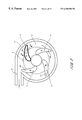
- FIG. 9 is a perspective, cut away view of the impeller of FIG. 8 within the pump assembly of FIG. 7;
- FIG. 10 is a side section indicative view of the impeller of FIG. 8;
- FIG. 11 is a detailed view in side section of edge portions of the impeller of FIG. 10;
- FIG. 12 is a block diagram of an electronic driver circuit for the pump assembly of FIG. 7;
- FIG. 13 is a graph of head versus flow for the pump assembly of FIG. 7;
- FIG. 14 is a graph of pump efficiency versus flow for the pump assembly of FIG. 7;
- FIG. 15 is a graph of electrical power consumption versus flow for the pump assembly of FIG. 7;
- FIG. 16 is a plan, section view of the pump assembly showing a volute arrangement according to a preferred embodiment
- FIG. 17 is a plan, section view of a pump assembly showing an alternative volute arrangement
- FIG. 18 is a plan view of an impeller according to a further embodiment of the invention.
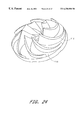
- FIG. 19 is a plan view of an impeller according to a further embodiment of the invention.
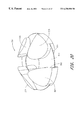
- FIG. 20 is a perspective view of an impeller according to a further embodiment of the invention.
- FIG. 21 is a perspective view of an impeller according to yet a further embodiment of the invention.
- FIG. 22 is a perspective, partially cut away view of an impeller according to yet a further embodiment of the invention.
- FIG. 23 is a top, perspective view of the impeller of FIG. 22;
- FIG. 24 is a perspective view of the impeller of FIG. 22 with its top shroud removed;
- FIG. 25 illustrates an alternative embodiment wherein the deformed surface is located on the pump housing.
- FIG. 26 illustrates a further embodiment wherein deformed surfaces are located both on the impeller and on the housing.
- FIG. 27 illustrates diagramatically the basis of operation of the “deformed surfaces” utilised for hydrodymanic suspension of embodiments of the invention.
- the pump assemblies according to various preferred embodiments to be described below all have particular, although not exclusive, application for implantation in a mammalian body so as to at least assist, if not take over, the function of the mammalian heart. In practice this is performed by placing the pump assembly entirely within the body of the mammal and connecting the pump between the left ventricle and the aorta so as to assist left side heart function. It may also be connected to the right ventricle and pulmonary artery to assist the right side of the heart.
- the pump assembly includes an impeller which is fully sealed within the pump body and so does not require a shaft extending through the pump body to support it.
- the impeller is suspended, in use, within the pump body by the operation of hydrodynamic forces imparted as a result of the interaction between the rotating impeller, the internal pump walls and the fluid which the impeller causes to be urged from an inlet of the pump assembly to an outlet thereof.
- a preferred embodiment of the invention is the centrifugal pump 1 , as depicted in FIGS. 1 and 2, intended for implantation into a human, in which case the fluid referred to below is blood.
- the pump housing 2 can be fabricated in two parts, a front part 3 in the form of a housing body and a back part 4 in the form of a housing cover, with a smooth join therebetween, for example at 5 in FIG. 1 .
- the pump 1 has an axial inlet 6 and a tangential outlet 7 .
- the rotating part 100 is of very simple form, comprising only blades 8 and a blade support 9 to hold those blades fixed relative to each other. The blades may be curved as depicted in FIG.
- This rotating part 100 will hereafter be called the impeller 100 , but it also serves as a bearing component and as the rotor of a motor configuration as to be further described below whereby a torque is applied by electromagnetic means to the impeller 100 .
- the impeller has no shaft and that the fluid enters the impeller from the region of its axis RR. Some of the fluid passes in front of the support cone 9 and some behind it, so that the pump 1 can be considered of two-sided open type, as compared to conventional open centrifugal pumps, which are only open on the front side.
- Approximate dimensions found adequate for the pump 1 to perform as a ventricular assist device, when operating at speeds in the range 1,500 rpm to 4,000 rpm, are outer blade diameter 40 mm, outer housing average diameter 60 mm, and housing axial length 40 mm.
- the gaps are made small because this leakage flow lowers the pump hydrodynamic efficiency.
- the gaps are made slightly smaller than is conventional in order that the leakage flow can be utilised to create a hydrodynamic bearing.
- the blades may also be tapered as depicted in FIGS. 3A and 3B, so that the gap 104 is larger at the leading edge 102 of the blade 8 than at the trailing edge 103 thereby providing one example of a “deformed surface” as described elsewhere in this specification.
- the fluid 105 which passes through the gap thus experiences a wedge shaped restriction which generates a thrust, as described in Reynolds' theory of lubrication (see, for example, “Modern Fluid Dynamics, Vol. 1 Incompressible Flow”, by N. Curle and H. J. Davies, Van Nostrand, 1968).
- the thrust is proportional to the square of the blade thickness at the edge, and thus in this embodiment thick blades are favoured, since if the proportion of the pump cavity filled by blades is constant, then the net thrust force will be inversely proportional to the number of blades.
- the blade edges can be made to extend as tails from thin blades as depicted in FIG. 3C in order to increase the blade area adjacent the walls.
- the tails join adjacent blades so as to form a complete shroud with wedges or tapers incorporated therein.
- a shroud design as well as other variations on the blade structure will be described later in this specification.
- the housing front face 10 can be made conical, with an angle of around 45° so that it provides both axial and radial hydrodynamic forces. Other angles are suitable that achieve the functional requirements of this pump including the requirements for both axial and radial hydrodynamic forces.
- the housing back face 11 can include a roughly conical extension 12 pointing into the pump cavity 106 , to eliminate or minimise the effect of the flow stagnation point on the axis of the back housing.
- extension 12 can resemble an impeller eye to make the flow mixed.
- the housing back face 11 is made flat over the bearing surfaces, i.e. under the blade edges. With this the case, a slacker tolerance on the alignment between the axes of the front part 3 and back part 4 of the housing 2 is permissible.
- An alternative is to make the back face 11 conical at the bearing surfaces, with taper in the opposite direction to the front face 10 , so that the hydrodynamic forces from the back face will also have radial components. Tighter tolerance on the axes alignment would then be required, and some of the flow would have to undergo a reversal in its axial direction. Again a roughly conical extension (like 12 ) will be needed. There may be some advantage in making the housing surfaces and blade edges non-straight, with varying tangent angle, although this will impose greater manufacturing complexity.
- the amount of material removed simply varies linearly or approximately linearly across the blade.
- the resulting blade edges are then planes at a slight inclination to the back face.
- the initial blade edges are curved and the taper only removes a relatively small amount of material so they still appear curved.
- Alternative taper shapes can include a step in the blade edge, though the corner in that step would represent a stagnation line posing a thrombosis risk.
- the hydrodynamic force is maximal if the gap at the leading edge is approximately double that at the trailing edge.
- the taper which equals the leading edge gap minus the trailing edge gap, should be chosen to match a nominal minimum gap, once the impeller has shifted towards that edge.
- Dimensions which have been found to give adequate thrust forces are a taper of around 0.05 mm for a nominal minimum gap of around 0.05 mm, and an average circumferential blade edge thickness of around 6 mm for 4 blades.
- the taper is measured within the plane perpendicular to the axis.
- the axial length of the housing between the front and back faces at any position should then be made about 0.2 mm greater than the axial length of the blade, when it is coaxial with the housing, so that the minimum gaps are both about 0.1 mm axially when the impeller 100 is centrally positioned within the housing 2 . Then, for example, if the impeller shifts axially by 0.05 mm, the minimum gaps will be 0.05 mm at one face and 0.15 mm at the other face. The thrust increases with decreasing gap and would be much larger from the 0.05 mm gap than from the 0.15 mm gap, about 14 times larger for the above dimensions. Thus there is a net restoring force away from the smaller gap.
- the impeller will continually shift its position and alignment, varying the gaps in such a way that the total force and torque on the impeller 100 match that demanded by inertia.
- the gaps are so small, however, that the variation in hydrodynamic efficiency will be small, and the pumping action of the blades will be approximately the same as when the impeller is centrally located.
- a major advantage of the open blades of the present invention is that a fluid element that does pass through a blade edge gap will have very short residence time in that gap, around 2 ⁇ 10 ⁇ 3 S, and the fluid element will most likely be swept though the pump without passing another blade edge.
- typical working clearances and working movement for the impeller 8 with respect to the upper and lower housing surfaces 10 , 11 is of the order of 100 microns clearance at the top and at the bottom.
- gravitational and other forces will bias the impeller 8 closer to one or other of the housing walls resulting, typically in a clearance at one interface of the order of 50 microns and a corresponding larger clearance at the other interface of the order of 150 microns.
- likely maximum practical clearances will range from 300 microns down to 1 micron.
- Typical restoring forces for a 25 gram rotor mass spinning at 2200 rpm are 1.96 Newtons at a 20 micron clearance extending to 0.1 Newtons at an 80 micron clearance.
- the radial force on the impeller depends critically on the shape of the output flow collector or volute 13 .
- the shape should be designed to minimise the radial impeller force over the desired range of pump speeds, without excessively lowering the pump efficiency.
- the optimal shape will have a roughly helical perimeter between the “cutwater” and outlet.
- the radial force can also be reduced by the introduction of an internal division in the volute 13 to create a second output flow collector passage, with tongue approximately diametrically opposite to the tongue of the first passage.
- FIG. 2 An indicative plan view of impeller 100 relative to housing 2 is shown in FIG. 2 having a concentric volute 13 .
- FIG. 17 illustrates the alternative volute arrangement comprising a split volute created by volute barrier 107 which causes volute 108 in a first hemisphere of the housing 2 to split into first half volute 109 and second half volute 110 over the second hemisphere.
- the hemispheres are defined respectively on each side of a diameter of the housing 2 which passes through or near exit point 111 of outlet 7 .
- concentric volutes can be utilised, particularly where specific speed is relatively low.
- a vaneless diffuser may also reduce the radial force.
- the blade support cone 9 must then be shaped to minimise axial thrust on the impeller and minimise disturbance to the flow over the range of speeds, while maintaining sufficient strength to prevent relative blade movement.
- the key design parameter affecting the axial force is the angle of the cone.
- the cone is drawn in FIG. 1 as having the same internal diameter as the blades, which may aid manufacture. However, the cone could be made with larger or smaller internal diameter to the blades.
- any bulk hydrodynamic axial force on them can be balanced by shaping the support cone to produce an opposite bulk hydrodynamic axial force on it.
- the means of providing the driving torque on the impeller 100 of the preferred embodiment of the invention is to encapsulate permanent magnets 14 in the blades 8 of the impeller 100 and to drive them with a rotating magnetic field pattern from oscillating currents in windings 15 and 16 , fixed relative to the housing 2 .
- Magnets of high remanence such as sintered rare-earth magnets should be used to maximise motor efficiency.
- the magnets can be aligned axially but greater motor efficiency is achieved by tilting the magnetisation direction to an angle of around 15° to 30° outwards from the inlet axis, with 22.5° tilt suitable for a body of conical angle 45°.
- the magnetisation direction must alternate in polarity for adjacent blades. Thus there must be an even number of blades.
- blade number is preferred for the bearing force, and since two blades would not have sufficient bearing stiffness to rotation about an axis through the blades and perpendicular to the pump housing (unless the blades are very curved), four blades are recommended. A higher number of blades, for example 6 or 8 will also work.
- FIG. 4 Some possible options for locating the magnets 14 within the blades 8 are shown in FIG. 4 .
- the coating should also be sufficiently durable especially at blade corners to withstand rubbing during start-up or during inadvertent bearing touch down.
- inside walls of the pump housing 2 are also coated with a biologically compatible and wear resistant material such as diamond coating or titanium nitride so that wear on both of the touching surfaces is minimised.
- a biologically compatible and wear resistant material such as diamond coating or titanium nitride
- An acceptable coating thickness is approximately 1 micron.
- a suitable impeller manufacturing method is to die-press the entire impeller, blades and support cone, as a single axially aligned magnet.
- the die-pressing is much simplified if near axially uniform blades are used (blades with an overhang such as in FIG. 3C are precluded).
- the crushed rare-earth particles must be aligned in an axial magnetic field.
- This method of die-pressing with parallel alignment direction is cheaper for rare-earth magnets, although it produces slightly lower remanence magnets.
- the tolerance in die-pressing is poor, and grinding of the tapered blade edges is required.
- the magnet impeller can be coated, for example by physical vapour deposition, of titanium nitride for example, or by chemical vapour deposition, of a thin diamond coating or a teflon coating.
- the magnet material can be potted in titanium or a polymeric housing which is then, in turn, coated with a biologically compatible and tough material such as diamond coating or titanium nitride.
- the impeller must be placed in a special pulse magnetisation fixture, with an individual coil surrounding each blade.
- the support cone of a die-pressed magnet impeller acquires some magnetisation near the blades, with negligible influence.
- FIG. 4 B and FIG. 4C Alternative magnet locations are sketched in FIG. 4 B and FIG. 4C in which quadrilateral or circular cross-section magnets 14 are inserted into the blades. Sealing and smoothing of the blade edges over the insertion holes is then required to reinstate the taper.
- All edges in the pump should be radiused and surfaces smoothed to avoid possible damage to formed elements of the blood.
- the windings 15 and 16 of the preferred embodiment are slotless or air-gap windings with the same pole number as the impeller, namely four poles in the preferred embodiment.
- a ferromagnetic iron yoke 17 of conical form for the front winding and an iron ferromagnetic yoke 18 of annular form for the back winding may be placed on the outside of the windings to increase the magnetic flux densities and hence increase motor efficiency.
- the winding thicknesses should be designed for maximum motor efficiency, with the sum of their axial thicknesses somewhat less than but comparable to the magnet axial length.
- the yokes can be made of solid ferromagnetic material such as iron.
- the yokes 17 can be laminated, for example in layers or by helically winding thin strip, or can be made of iron/powder epoxy composite.
- the yokes should be positioned such that there is zero net axial magnetic force on the impeller when it is positioned centrally in the housing.
- the magnetic force is unstable and increases linearly with axial displacement of the impeller away from the central position, with the gradient being called the negative stiffness of the magnetic force.
- This unstable magnetic force must be countered by the hydrodynamic bearings, and so the stiffness should be made as small as possible. Choosing the yoke thickness such that the flux density is at the saturation level reduces the stiffness and gives minimum mass.
- An alternative can be to have no iron yokes, completely eliminating the unstable axial magnetic force, but the efficiency of such designs may be lower and the magnetic flux density in the immediate vicinity of the pump may violate safety standards and produce some tissue heating.
- the stiffness is acceptably small for slotless windings with the yokes present.
- Another alternative would be to insert the windings in slots in laminated iron stators which would increase motor efficiency and enable use of less magnet material and potentially lighter impeller blades.
- the unstable magnetic forces would be significant for such slotted motors.
- the necessity for fat blades to generate the required bearing forces in this embodiment allows room for large magnets, and so slotless windings are chosen in the preferred embodiment.
- FIG. 5A depicts the preferred topology for the body winding 15 , viewed from the inlet axis.
- the cover winding 16 looks similar but the coils need not avoid the inlet tube and so they appear more triangular in shape.
- the body winding has a more complex three-dimensional shape with bends at the ends of the body cone section.
- Each winding consists of three coils.
- Each coil is made from a number of turns of an insulated conductor such as copper with the number of turns chosen to suit the desired voltage.
- the coil side mid-lines span an angle of about 50°-100° at the axis when the coils are in position.
- the coils for body and cover are aligned axially and the axially adjacent coils are connected in either parallel or series connection to form one phase of the three phase winding.
- Parallel connection offers one means of redundancy in that if one coil fails, the phase can still carry current through the other coil.
- each of the coil and body winding has a neutral point connection as depicted in FIG. 5A, whereas in series connection, only one of the windings has a neutral point.
- FIG. 5B An alternative three phase winding topology, depicted in FIG. 5B, uses four coils per phase for each of the body and cover windings, with each coil wrapping around the yoke, a topology called a “Gramm ring” winding.
- FIG. 5C Yet another three phase winding topology, depicted in FIG. 5C, uses two coils per phase for each of the body and cover windings, and connects the coil sides by azimuthal end-windings as is standard motor winding practice.
- the coils are shown tilted to approximately follow the blade curvature, which can increase motor efficiency, especially for the phase energising strategy to be described below in which only one phase is energised at a time.
- the winding construction can be simplified by laying the coils around pins protruding from a temporary former, the pins shown as dots in 2 rings of 6 pins each in FIG. 5 C.
- the coils are labelled alphabetically in the order in which they would be layed, coils a and d for phase A, b and e for phase B, and c and f for phase C.
- the coil locations could be defined by thin fins, running between the pins in FIG. 5C, along the boundary between the coils.
- the coil connections depicted in FIG. 5C are those appropriate for the winding nearest the motor terminals for the case of series connection, with the optional lead from the neutral point on the other winding included.
- FIGS. 5B and C allow the possibility of higher motor efficiency but only if significantly higher coil mass is allowed, and since option FIG. 5A is more compact and simpler to manufacture, it is the preferred option. Material ribs between the coils of option FIG. 5A can be used to stiffen the housing.
- Multi-stranded flexible conductors within a suitable biocompatible cable can be used to connect the motor windings to a motor controller.
- the energisation of the three phases can be performed by a standard sensorless controller, in which two out of six semiconducting switches in a three phase bridge are turned on at any one time.
- a standard sensorless controller in which two out of six semiconducting switches in a three phase bridge are turned on at any one time.
- the two housing components 3 and 4 are made by injection moulding from non-electrically conducting plastic materials such as Lexan polycarbonate plastic.
- the housing components can be made from ceramics.
- the windings and yokes are ideally encapsulated within the housing during fabrication moulding. In this way, the separation between the winding and the magnets is minimised, increasing the motor efficiency, and the housing is thick, increasing its mechanical stiffness.
- the windings can be positioned outside the housing, of thickness at least around 2 mm for sufficient stiffness.
- the housing material plastic is hygroscopic or if the windings are outside the housing, it may be necessary to first enclose the windings and yoke in a very thin impermeable shell.
- the shell should be non-conducting (such as ceramic or plastic), but titanium of around 0.1 mm to 0.2 mm thickness would give sufficiently low eddy losses. Encapsulation within such a shell would be needed to prevent winding movement.
- the housing components 3 and 4 may be made from a biocompatible metallic material of low electrical conductivity, such as Ti-6Al-4V.
- the material must be as thin as possible, e.g. 0.1 mm to 0.5 mm, wherever the material experiences high alternating magnetic flux densities, such as between the coils and the housing inner surfaces 10 and 11 .
- the combining of the motor and bearing components into the impeller in the preferred embodiment provides several key advantages.
- the rotor consequently has very simple form, with the only cost of the bearing being tight manufacturing tolerances.
- the rotor mass is very low, minimising the bearing force needed to overcome weight. Also, with the bearings and the motor in the same region of the rotor, the bearings forces are smaller than if they had to provide a torque to support magnets at an extremity of the rotor.
- a disadvantage of the combination of functions in the impeller is that its design is a coupled problem.
- the optimisation should ideally link the fluid dynamics, magnetics and bearing thrust calculations.
- the blade thickness can be first roughly sized to give adequate motor efficiency and sufficient bearing forces with a safety margin.
- both requirements are met for four blades of approximate average circumferential thickness 6 mm or more.
- the housing, blade, and support cone shapes can then be designed using computational fluid dynamics, maintaining the above minimum average blade thickness.
- the motor stator i.e. winding and yoke, can be optimised for maximum motor efficiency.
- FIG. 6 depicts an alternative embodiment of the invention as an axial pump.
- the pump housing is made of two parts, a front part 19 and a back part 20 , joined for example at 21 .
- the pump has an axial inlet 22 and axial outlet 23 .
- the impeller comprises only blades 24 mounted on a support cylinder 25 of reducing radius at each end.
- An important feature of this embodiment is that the blade edges are tapered to generate hydrodynamic thrust forces which suspend the impeller. These forces could be used for radial suspension alone from the straight section 26 of the housing, with some alternative means used for axial suspension, such as stable axial magnetic forces or a conventional tapered-land type hydrodynamic thrust bearing.
- FIG. 6 proposes a design which uses the tapered blade edges to also provide an axial hydrodynamic bearing.
- the housing is made with a reducing radius at its ends to form a front face 27 and a back face 28 from which the axial thrusts can suspend the motor axially.
- Magnets are embedded in the blades with blades having alternating polarity and four blades being recommended. Iron in the outer radius of the support cylinder 25 can be used to increase the magnet flux density. Alternatively, the magnets could be housed in the support cylinder and iron could be used in the blades.
- a slotless helical winding 29 is recommended, with outward bending end-windings 30 at one end to enable insertion of the impeller and inward bending windings 31 at the other end to enable insertion of the winding into a cylindrical magnetic yoke 32 .
- the winding can be encapsulated in the back housing part 20 .
- FIGS. 7 to 15 inclusive there is shown a further preferred embodiment of the pump assembly 200 .
- the pump assembly 200 comprises a housing body 201 adapted for bolted connection to a housing cover 202 and so as to define a centrifugal pump cavity 203 therewithin.
- the cavity 203 houses an impeller 204 adapted to receive magnets 205 within cavities 206 defined within blades 207 .
- the blades 207 are supported from a support cone 208 .
- a body winding 209 symmetrically mounted around inlet 210 and housed between the housing body 201 and a body yoke 211 .
- cover winding 212 located within winding cavity 213 which, in turn, is located within housing cover 202 and closed by cover yoke 214 .
- the windings 212 and 209 are supplied from the electronic controller of FIG. 12 as for the first embodiment the windings are arranged to receive a three phase electrical supply and so as to set up a rotating magnetic field within cavity 203 which exerts a torque on magnets 205 within the impeller 204 so as to urge the impeller 204 to rotate substantially about central axis TT of cavity 203 and in line with the longitudinal axis of inlet 210 .
- the impeller 204 is caused to rotate so as to urge fluid (in this case blood) around volute 215 and through outlet 216 .
- the assembly is bolted together in the manner indicated by screws 217 .
- the yokes 211 , 214 are held in place by fasteners 218 .
- press fitting is possible provided sufficient integrity of seal can be maintained.
- FIG. 8 shows the impeller 204 of this embodiment and clearly shows the support cone 208 from which the blades 207 extend.
- the axial cavity 219 which is arranged, in use, to be aligned with the longitudinal axis of inlet 210 and through which blood is received for urging by blades 207 is clearly visible.
- FIG. 9 shows the axial cavity 219 and also the magnet cavities 206 located within each blade 207 .
- the preferred cone structure 220 extending from housing cover 202 aligned with the axis of inlet 210 and axial cavity 219 of impeller 204 is also shown.
- FIG. 10 is a side section, indicative view of the impeller 204 defining the orientations of central axis FF, top taper edge DD and bottom taper edge BB, which tapers are illustrated in FIG. 11 in side section view.
- FIG. 11A is a section of a blade 207 of impeller 204 taken through plane DD as defined in FIG. 10 and shows the top edge 221 to be profiled from a leading edge 223 to a trailing edge 224 as follows: central portion 227 comprises an ellipse with centre on the dashed midline having a semi-major axis of radius 113 mm and a semi-minor axis of radius 80 mm and then followed by leading conical surface 225 and trailing conical surface 226 on either side thereof as illustrated in FIG. 11 A.
- the leading surface 225 has radius 0.05 mm less than the trailing surface 226 .
- This prescription is for a taper which can be achieved by a grinding wheel, but many alternative prescriptions could be devised to give a taper of similar utility.
- the leading edge 223 is radiused as illustrated.
- FIG. 11B illustrates in cross-section the bottom edge 222 of blade 207 cut along plane BB of FIG. 10 .
- the bottom edge includes cap 228 utilised for sealing magnet 205 within cavity 206 .
- substantially the entire edge comprises a straight taper with a radius of 0.05 mm at leading edge 229 and a radius of 0.25 mm at trailing edge 230 .
- the blade 207 is 6.0 mm in width excluding the radii at either end.
- FIG. 12 comprises a block diagram of the electrical controller suitable for driving the pump assembly 200 and comprises a three phase commutation controller 232 adapted to drive the windings 209 , 212 of the pump assembly.
- the commutation controller 232 determines relative phase and frequency values for driving the windings with reference to set point speed input 233 derived from physiological controller 234 which, in turn, receives control inputs 235 comprising motor current input and motor speed (derived from the commutation controller 232 ), patient blood flow 236 , and venous oxygen saturation 237 .
- the pump blood flow can be approximately inferred from the motor speed and current via curve-fitted formulae.
- FIG. 13 is a graph of pressure against flow for the pump assembly 200 where the fluid pumped is 18% glycerol for impeller rotation velocity over the range 1500 RPM to 2500 RPM.
- the 18% glycerol liquid is believed to be a good analogue for blood under certain circumstances, for example in the housing gap.
- FIG. 14 graphs pump efficiency against flow for the same fluid over the same speed ranges as for FIG. 13 .
- FIG. 15 is a graph of electrical power consumption against flow for the same fluid over the same speed ranges as for FIG. 13 .
- the common theme running through the first, second and third embodiments described thus far is the inclusion in the impeller of a taper or other deformed surface which, in use, moves relative to the adjacent housing wall thereby to cause a restriction with respect to the line of movement of the taper or deformity thereby to generate thrust upon the impeller which includes a component substantially normal to the line of movement of the surface and also normal to the adjacent internal pump wall with respect to which the restriction is defined for fluid located therebetween.
- At least one set of surfaces must be angled with respect to the longitudinal axis of the impeller (preferably at approximately 45° thereto) thereby to generate or resolve opposed radial forces and an axial force which can be balanced by a corresponding axial force generated by at least one other tapered or deformed surface located elsewhere on the impeller.
- top surfaces of the blades 8 , 207 are angled at approximately 45° with respect to the longitudinal axis of the impeller 100 , 204 and arranged for rotation with respect to the internal walls of a similarly angled conical pump housing.
- the top surfaces of the blades are deformed so as to create the necessary restriction in the gap between the top surfaces of the blades and the internal walls of the conical pump housing thereby to generate a thrust which can be resolved to both radial and axial components.
- the bottom faces of the blades 8 , 207 comprise surfaces substantially lying in a plane at right angles to the axis of rotation of the impeller and, with their deformities define a gap with respect to a lower inside face of the pump housing against which a substantially only axial thrust is generated.
- Such arrangements can include a double cone arrangement where the conical top surface of the blades is mirrored in a corresponding bottom conical surface.
- the only concern with this arrangement is the increased depth of pump which can be a problem for in vivo applications where size minimisation is an important criteria.
- FIG. 18 a further embodiment of the invention is illustrated comprising a plan view of the impeller 300 forming part of a “channel” pump.
- the blades 301 have been widened relative to the blades 207 of the third embodiment to the point where they are almost sector-shaped and the flow gaps between adjacent blades 301 , as a result, take the form of a channel 302 , all in communication with axial cavity 303 .
- impeller 304 includes sector-shaped blades 305 having curved leading and trailing portions 306 , 307 respectively thereby defining channels 308 having fluted exit portions 309 .
- the radial and axial hydrodynamic forces are generated by appropriate profiling of the top and bottom faces of the blades 301 , 305 (not shown in FIGS. 18 and 19 ).
- FIG. 20 illustrates a perspective view of an impeller 304 which follows the theme of the impeller arrangement of FIGS. 18 and 19 in perspective view and where like parts are numbered as for FIG. 19 .
- the four blades 305 are joined at mid-portions thereof by a blade support in the form of a conical rim 350 and have edge portions which are shaped so as to have an increased curvature on the trailing edge 351 thereof compared with the leading edge 352 .
- a fifth embodiment of a pump assembly according to the invention comprises an impeller 410 as illustrated in FIG. 21 where, conceptually, the upper and lower surfaces of the blades of previous embodiments are interconnected by a top shroud 411 and a bottom shroud 412 .
- the blades 413 can be reduced to a very small width as the hydrodynamic behaviour imparted by their surfaces in previous embodiments is now given effect by the profiling of the shrouds 411 , 412 which, in this instance, comprises a series of smooth-edged wedges with the leading surface of one wedge directly interconnected to the trailing edge of the next leading wedge 414 .
- top shroud 411 is of overall conical shape thereby to impart both radial and axial thrust forces whilst the bottom shroud 412 is substantially planar thereby to impart substantially only axial thrust forces.
- FIG. 21 shows the surfaces of the shroud 411 angled at approximately 45° to the vertical, other inclinations are possible extending to an inclination of 0° to the vertical which is to say the impeller 410 can take the form of a cylinder with surface rippling or other deformations which impart the necessary hydrodynamic lift, in use.
- FIGS. 22 to 24 a specific example of the concept embodied in FIG. 21 is illustrated and wherein like components are numbered as for FIG. 21 .
- the blades 413 are thin compared to previous embodiments and, in this instance, are arcuate channels 416 therebetween which allow fluid communication from a centre volume 417 to the periphery 418 of the impeller 410 .
- the wedges 414 are separated one from the other on each shroud by channels 419 .
- the channels extend radially down the shroud from the centre volume 417 to the periphery 418 .
- the magnets required for the driving torque can be contained within the top or bottom volute or both, along with the optional soft magnetic yokes to increase motor efficiency.
- a variation of this embodiment is to have the wedge profiling cut into the inner surfaces of the housing and have smooth shroud surfaces.
- FIG. 25 In contrast to the embodiments illustrated with respect to FIGS. 3A, 3 B and 3 C an arrangement is shown in FIG. 25 wherein the “deformed surface” comprises a stepped formation 510 forming part of an inner wall of the pump housing (not shown).
- the rotor including blade 511 includes a flat working surface 512 (and not having a deformed surface therein) which is adapted for relative movement in the direction of the arrow shown with respect to the stepped formation 510 thereby to generate hydrodynamic thrust therebetween.
- FIG. 26 there is shown an arrangement of rotor blade 610 with respect to stepped formation 611 and wherein the rotor blade 610 includes a deformed surface 612 at a working face thereof.
- the deformation comprises curved edges 613 , 614 .
- relative movement of the rotor blade 610 in the direction of the arrow with respect to deformed surface 611 forming part of the pump housing (not shown) causes relative hydrodynamic thrust therebetween.
- this specification describes the suspension of an impeller 600 within a pump housing 601 by the use of hydrodynamic forces.
- the suspension of the impeller 600 is performed dominantly which is to say exclusively by hydrodynamic forces.
- the hydrodynamic forces are forces which are created by relative movement between two surfaces which have a fluid in the gap between the two surfaces.
- the fluid is blood.
- hydrodynamic forces can arise during relative movement between two surfaces even where those surfaces are substantially entirely parallel to each other or non-deformed. However, in this specification, hydrodynamic forces are caused to arise during relative movement between two surfaces where at least one of the surfaces includes a “deformed surface”.
- deformed surface means a surface which includes an irregularity relative to a surface which it faces such that, when the surface moves in a predetermined direction relative to the surface which it faces the fluid located in the gap there between experiences a change in relative distance between the surfaces along the line of movement thereby to cause a hydrodynamic force to arise therebetween in the form of a thrust force including at least a component substantially normal to the plane of the gap defined at any given point between the facing surfaces.
- first deformed surface 603 forming at least part of a first face 604 of impeller 600 and a second deformed surface 605 on a second face 606 of the impeller 600 .
- the inset of FIG. 27 illustrates conceptually how the first deformed surface 603 may form only part of the first face 604 .
- the first deformed surface 603 faces first inner surface 607 of the pump housing 601 whilst second deformed surface 605 faces second inner surface 608 of the pump housing 601 .
- first gap 609 defined between first deformed surface 603 and first inner surface 607 has a fluid comprising blood located therein whilst second gap 610 defined between second deformed surface 605 and second inner surface 608 also has a fluid comprising blood located therein.
- impeller 600 is caused to rotate about impeller axis 611 such that relative movement across first gap 609 between first deformed surface 603 and first inner face 607 occurs and also relative movement across second gap 610 between second deformed surface 605 and second inner surface 608 occurs.
- the orientation of the deformities of first deformed surface 603 and second deformed surface 605 relative to the line of movement of the deformed surfaces 603 , 605 relative to the inner surfaces 607 , 608 is such that the fluid in the gaps 609 , 610 experiences a change in height of the gap 609 , 610 as a function of time and with the rate of change dependant on the shape of the deformities of the deformed surfaces and also the rate of rotation of the impeller 600 relative to the housing 601 .
- the height of the gap between the inner surface 607 or 608 and corresponding deformed surface 603 or 605 will vary with time due to passage of the deformed surface 603 or 605 over the inner surface.
- Hydrodynamic forces in the form of thrust forces normal to the line of relative movement of the respective deformed surfaces 603 , 605 relative to the inner surfaces 607 , 608 thus arise.
- first gap 609 lies substantially in a single plane whilst the second gap 610 is in the form of a cone and angled at an acute angle relative to the plane of the first gap 609 .
- first gap 609 and second gap 610 are substantially normal to and distributed across both the predominantly flat plane of first deformed surface 603 and normal to the substantially conical surface of second deformed surface 605 thereby permitting restoring forces to be applied between the impeller 600 and the pump housing 601 thereby to resist forces which seek to translate the impeller 600 in space relative to the pump housing 601 and also to rotate the impeller 600 about any axis (other than about the impeller axis 611 ) relative to the pump housing 601 .
- This arrangement substantially resists five degrees of freedom of movement of impeller 600 with respect to the housing 601 and does so predominantly without any external intervention to control the position of the impeller with respect to the housing given that disturbing forces from other sources, most notably magnetic forces on the impeller due to its use as rotor of the motor are net zero when the impeller occupies a suitable equilibrium position.
- the balance of all forces on the rotor, effected by manipulation of magnetic and other external sources, may be adjusted such that the rotor is predominantly hydrodynamically born.
- Radial or near-radial off-flow from the impeller can be chosen in order to yield a “flat” pump characteristic (HQ) curve.
- the pump assembly 1 , 200 is applicable to pump fluids such as blood on a continuous basis. With its expected reliability it is particularly applicable as an in vivo heart assist pump.
- the pump assembly can also be used with advantage for the pumping of other fluids where damage to the fluid due to high shear stresses must be avoided or where leakage of the fluid must be prevented with a very high degree of reliability—for example where the fluid is a dangerous fluid.
Landscapes
- Engineering & Computer Science (AREA)
- Health & Medical Sciences (AREA)
- Mechanical Engineering (AREA)
- Heart & Thoracic Surgery (AREA)
- General Engineering & Computer Science (AREA)
- Life Sciences & Earth Sciences (AREA)
- Veterinary Medicine (AREA)
- Hematology (AREA)
- Anesthesiology (AREA)
- Animal Behavior & Ethology (AREA)
- General Health & Medical Sciences (AREA)
- Public Health (AREA)
- Biomedical Technology (AREA)
- Cardiology (AREA)
- Physics & Mathematics (AREA)
- Fluid Mechanics (AREA)
- Electromagnetism (AREA)
- External Artificial Organs (AREA)
- Structures Of Non-Positive Displacement Pumps (AREA)
Abstract
Description
Claims (49)
Priority Applications (16)
| Application Number | Priority Date | Filing Date | Title |
|---|---|---|---|
| US09/299,038 US6250880B1 (en) | 1997-09-05 | 1999-04-23 | Rotary pump with exclusively hydrodynamically suspended impeller |
| EP00918592A EP1176999B8 (en) | 1999-04-23 | 2000-04-20 | A rotary blood pump and control system therefor |
| AT00918592T ATE300322T1 (en) | 1999-04-23 | 2000-04-20 | ROTARY BLOOD PUMP AND CONTROL SYSTEM THEREOF |
| DE60021554T DE60021554T2 (en) | 1999-04-23 | 2000-04-20 | ROTATION BLOOD PUMP AND CONTROL SYSTEM THEREFOR |
| CA002370755A CA2370755C (en) | 1999-04-23 | 2000-04-20 | A rotary blood pump and control system therefor |
| CN00809402A CN1372479A (en) | 1999-04-23 | 2000-04-20 | Rotary blood pump and control system therefor |
| JP2000613498A JP2002541986A (en) | 1999-04-23 | 2000-04-20 | Rotary blood pump and control device therefor |
| AU39482/00A AU760610C (en) | 1999-04-23 | 2000-04-20 | A rotary blood pump and control system therefor |
| EP05076649A EP1602386A1 (en) | 1999-04-23 | 2000-04-20 | A rotary blood pump and control system therefor |
| PCT/AU2000/000355 WO2000064509A1 (en) | 1999-04-23 | 2000-04-20 | A rotary blood pump and control system therefor |
| US09/893,319 US6638011B2 (en) | 1997-09-05 | 2001-06-26 | Rotary pump with exclusively hydrodynamically suspended impeller |
| US10/634,211 US6966748B2 (en) | 1997-09-05 | 2003-08-05 | Rotary pump with exclusively hydrodynamically suspended impeller |
| US11/212,227 US7476077B2 (en) | 1997-09-05 | 2005-08-26 | Rotary pump with exclusively hydrodynamically suspended impeller |
| US12/347,263 US8002518B2 (en) | 1997-09-05 | 2008-12-31 | Rotary pump with hydrodynamically suspended impeller |
| US13/181,452 US8366381B2 (en) | 1997-09-05 | 2011-07-12 | Rotary pump with hydrodynamically suspended impeller |
| US13/758,887 US20130225910A1 (en) | 1997-09-05 | 2013-02-04 | Rotary Pump with Hydrodynamically Suspended Impeller |
Applications Claiming Priority (5)
| Application Number | Priority Date | Filing Date | Title |
|---|---|---|---|
| AUPO9027A AUPO902797A0 (en) | 1997-09-05 | 1997-09-05 | A rotary blood pump with hydrodynamically suspended impeller |
| AUP09027 | 1997-09-05 | ||
| PCT/AU1998/000725 WO1999012587A1 (en) | 1997-09-05 | 1998-09-07 | A rotary pump with hydrodynamically suspended impeller |
| US09/281,608 US6227797B1 (en) | 1997-09-05 | 1999-03-30 | Rotary pump with hydrodynamically suspended impeller |
| US09/299,038 US6250880B1 (en) | 1997-09-05 | 1999-04-23 | Rotary pump with exclusively hydrodynamically suspended impeller |
Related Parent Applications (1)
| Application Number | Title | Priority Date | Filing Date |
|---|---|---|---|
| US09/281,608 Continuation-In-Part US6227797B1 (en) | 1997-05-09 | 1999-03-30 | Rotary pump with hydrodynamically suspended impeller |
Related Child Applications (2)
| Application Number | Title | Priority Date | Filing Date |
|---|---|---|---|
| US09/893,319 Continuation US6638011B2 (en) | 1997-09-05 | 2001-06-26 | Rotary pump with exclusively hydrodynamically suspended impeller |
| US09/893,319 Continuation-In-Part US6638011B2 (en) | 1997-09-05 | 2001-06-26 | Rotary pump with exclusively hydrodynamically suspended impeller |
Publications (2)
| Publication Number | Publication Date |
|---|---|
| US20010002234A1 US20010002234A1 (en) | 2001-05-31 |
| US6250880B1 true US6250880B1 (en) | 2001-06-26 |
Family
ID=46256404
Family Applications (4)
| Application Number | Title | Priority Date | Filing Date |
|---|---|---|---|
| US09/299,038 Expired - Lifetime US6250880B1 (en) | 1997-09-05 | 1999-04-23 | Rotary pump with exclusively hydrodynamically suspended impeller |
| US09/893,319 Expired - Lifetime US6638011B2 (en) | 1997-09-05 | 2001-06-26 | Rotary pump with exclusively hydrodynamically suspended impeller |
| US10/634,211 Expired - Lifetime US6966748B2 (en) | 1997-09-05 | 2003-08-05 | Rotary pump with exclusively hydrodynamically suspended impeller |
| US11/212,227 Expired - Fee Related US7476077B2 (en) | 1997-09-05 | 2005-08-26 | Rotary pump with exclusively hydrodynamically suspended impeller |
Family Applications After (3)
| Application Number | Title | Priority Date | Filing Date |
|---|---|---|---|
| US09/893,319 Expired - Lifetime US6638011B2 (en) | 1997-09-05 | 2001-06-26 | Rotary pump with exclusively hydrodynamically suspended impeller |
| US10/634,211 Expired - Lifetime US6966748B2 (en) | 1997-09-05 | 2003-08-05 | Rotary pump with exclusively hydrodynamically suspended impeller |
| US11/212,227 Expired - Fee Related US7476077B2 (en) | 1997-09-05 | 2005-08-26 | Rotary pump with exclusively hydrodynamically suspended impeller |
Country Status (1)
| Country | Link |
|---|---|
| US (4) | US6250880B1 (en) |
Cited By (42)
| Publication number | Priority date | Publication date | Assignee | Title |
|---|---|---|---|---|
| US6368083B1 (en) * | 1996-02-20 | 2002-04-09 | Kriton Medical, Inc. | Sealless rotary blood pump |
| US6543992B2 (en) * | 2000-06-23 | 2003-04-08 | Rolls-Royce Plc | Control arrangement |
| US6676383B2 (en) * | 2001-08-16 | 2004-01-13 | Levitronix Llc | Method and a pump apparatus for the generation of an adjustable, substantially constant volume flow of a fluid and a use of this method |
| US20040028525A1 (en) * | 1997-09-05 | 2004-02-12 | Woodard John C. | Rotary pump with exclusively hydrodynamically suspended impeller |
| US20040030216A1 (en) * | 1997-09-05 | 2004-02-12 | Woodard John Campbell | Rotary pump with hydrodynamically suspended impeller |
| US20040090874A1 (en) * | 2002-11-08 | 2004-05-13 | Kunjithapatham Balasubramanian | Apparatus and method for effective reduction of a laser beam spot size |
| US6761532B2 (en) | 2001-03-14 | 2004-07-13 | Vascor, Inc. | Touch down of blood pump impellers |
| US20040143151A1 (en) * | 2002-12-17 | 2004-07-22 | Terumo Kabushiki Kaisha | Centrifugal blood pump apparatus |
| US20050025630A1 (en) * | 1999-04-23 | 2005-02-03 | Ayre Peter Joseph | Rotary blood pump and control system therefor |
| US20050084399A1 (en) * | 2003-09-18 | 2005-04-21 | Wampler Richard K. | Rotary blood pump |
| US20050104369A1 (en) * | 2002-02-20 | 2005-05-19 | Webb Ian R. | Anchoring device for pipe coupling |
| US20050107657A1 (en) * | 2002-03-08 | 2005-05-19 | Michel Carrier | Dual inlet mixed-flow blood pump |
| US20050196293A1 (en) * | 1999-04-23 | 2005-09-08 | Ayre Peter J. | Rotary blood pump and control system therefor |
| US20050254976A1 (en) * | 2003-05-13 | 2005-11-17 | Michel Carrier | Blood pump with constant blood pumping area |
| US20060122456A1 (en) * | 2004-12-03 | 2006-06-08 | Larose Jeffrey A | Wide blade, axial flow pump |
| US20060245959A1 (en) * | 2005-04-29 | 2006-11-02 | Larose Jeffrey A | Multiple rotor, wide blade, axial flow pump |
| US20070054256A1 (en) * | 2005-09-06 | 2007-03-08 | Jeremy Low | Mock circulatory apparatus |
| US20070078293A1 (en) * | 2005-10-05 | 2007-04-05 | Shambaugh Charles R Jr | Impeller for a rotary ventricular assist device |
| US20070145855A1 (en) * | 2005-12-28 | 2007-06-28 | Ming-Hwa Liu | Motor device utilizing magnetic force to drive a rotor |
| US20070276480A1 (en) * | 2003-10-09 | 2007-11-29 | Tansley Geoffrey D | Impeller |
| US20070280841A1 (en) * | 2006-01-13 | 2007-12-06 | Larose Jeffrey A | Hydrodynamic thrust bearings for rotary blood pumps |
| US20080199334A1 (en) * | 2005-05-07 | 2008-08-21 | Grundfos Management A/S | Pump Assembly |
| US20090084502A1 (en) * | 2007-09-28 | 2009-04-02 | Tokyo Electron Limited | Plasma processing apparatus |
| US20090203957A1 (en) * | 2008-02-08 | 2009-08-13 | Larose Jeffrey A | Ventricular assist device for intraventricular placement |
| US7993260B2 (en) | 1997-10-09 | 2011-08-09 | Thoratec Corporation | Implantable heart assist system and method of applying same |
| US20110238172A1 (en) * | 2006-08-06 | 2011-09-29 | Mustafa Akdis | Blood pump |
| US20120003100A1 (en) * | 2010-07-05 | 2012-01-05 | Rolls-Royce Plc | Composite turbomachine blade |
| US20130088835A1 (en) * | 2011-10-11 | 2013-04-11 | Alcatel-Lucent. | Active air-cooling device for electronic circuits |
| US8672611B2 (en) | 2006-01-13 | 2014-03-18 | Heartware, Inc. | Stabilizing drive for contactless rotary blood pump impeller |
| US8905910B2 (en) | 2010-06-22 | 2014-12-09 | Thoratec Corporation | Fluid delivery system and method for monitoring fluid delivery system |
| US9000604B2 (en) | 2010-04-30 | 2015-04-07 | Clean Current Limited Partnership | Unidirectional hydro turbine with enhanced duct, blades and generator |
| US9089635B2 (en) | 2010-06-22 | 2015-07-28 | Thoratec Corporation | Apparatus and method for modifying pressure-flow characteristics of a pump |
| US9217435B2 (en) | 2012-10-23 | 2015-12-22 | Nidec Motor Corporation | Axial flow pump with integrated motor |
| US9429160B2 (en) | 2012-03-23 | 2016-08-30 | Terumo Kabushiki Kaisha | Centrifugal pump and method of manufacturing centrifugal pump |
| US9512852B2 (en) | 2006-03-31 | 2016-12-06 | Thoratec Corporation | Rotary blood pump |
| US10377097B2 (en) * | 2016-06-20 | 2019-08-13 | Terumo Cardiovascular Systems Corporation | Centrifugal pumps for medical uses |
| US11499420B2 (en) | 2019-12-18 | 2022-11-15 | Baker Hughes Oilfield Operations Llc | Oscillating shear valve for mud pulse telemetry and operation thereof |
| US11712501B2 (en) | 2019-11-12 | 2023-08-01 | Fresenius Medical Care Deutschland Gmbh | Blood treatment systems |
| US11730871B2 (en) | 2019-11-12 | 2023-08-22 | Fresenius Medical Care Deutschland Gmbh | Blood treatment systems |
| US11753932B2 (en) | 2020-06-02 | 2023-09-12 | Baker Hughes Oilfield Operations Llc | Angle-depending valve release unit for shear valve pulser |
| US11752247B2 (en) | 2019-11-12 | 2023-09-12 | Fresenius Medical Care Deutschland Gmbh | Blood treatment systems |
| US11925736B2 (en) | 2019-11-12 | 2024-03-12 | Fresenius Medical Care Deutschland Gmbh | Blood treatment systems |
Families Citing this family (95)
| Publication number | Priority date | Publication date | Assignee | Title |
|---|---|---|---|---|
| US7070398B2 (en) * | 2003-09-25 | 2006-07-04 | Medforte Research Foundation | Axial-flow blood pump with magnetically suspended, radially and axially stabilized impeller |
| US7229258B2 (en) * | 2003-09-25 | 2007-06-12 | Medforte Research Foundation | Streamlined unobstructed one-pass axial-flow pump |
| US7296959B2 (en) * | 2003-09-29 | 2007-11-20 | James Darrin Davis | Deer stand and deer carrier rack for an ATV |
| DE102004019721A1 (en) * | 2004-03-18 | 2005-10-06 | Medos Medizintechnik Ag | pump |
| US20050261543A1 (en) * | 2004-05-18 | 2005-11-24 | Yusuke Abe | Implantable artificial ventricular assist device |
| US20060021735A1 (en) * | 2004-07-27 | 2006-02-02 | Industrial Design Laboratories Inc. | Integrated cooler for electronic devices |
| EP1789112B1 (en) | 2004-08-13 | 2010-09-29 | Delgado, Reynolds M., III | Apparatus for long-term assisting a left ventricle to pump blood |
| US7393181B2 (en) | 2004-09-17 | 2008-07-01 | The Penn State Research Foundation | Expandable impeller pump |
| US20090087563A1 (en) * | 2004-11-02 | 2009-04-02 | Gerald Voegele | Coating of displacer components (tooth components) for providing a displacer unit with chemical resistance and tribological protection against wear |
| US20070077155A1 (en) * | 2005-09-30 | 2007-04-05 | Intel Corporation | Centrifugal pump with hydrodynamic bearing and double involute |
| US20070177995A1 (en) * | 2006-02-01 | 2007-08-02 | Yoshio Yano | Pump device |
| US20070183908A1 (en) * | 2006-02-06 | 2007-08-09 | Yoshio Yano | Contactless centrifugal pump |
| CN101448535B (en) | 2006-03-23 | 2011-10-19 | 宾州研究基金会 | Heart assist device with expandable impeller pump |
| AU2007269050A1 (en) * | 2006-07-06 | 2008-01-10 | The Board Of Regents Of The University Of Texas System | Positive displacement pump system and method |
| EP2131888B1 (en) | 2007-02-26 | 2017-04-05 | HeartWare, Inc. | Intravascular ventricular assist device |
| FI7604U1 (en) * | 2007-04-27 | 2007-08-09 | Metso Automation Oy | Sen. |
| EP2145108B1 (en) * | 2007-04-30 | 2019-10-02 | HeartWare, Inc. | Centrifugal rotary blood pump |
| EP3050537A1 (en) | 2008-10-06 | 2016-08-03 | Indiana University Research and Technology Corporation | Methods and apparatus for active or passive assistance in the circulatory system |
| US9067005B2 (en) | 2008-12-08 | 2015-06-30 | Thoratec Corporation | Centrifugal pump apparatus |
| WO2010083282A1 (en) * | 2009-01-15 | 2010-07-22 | The Charles Stark Draper Laboratory, Inc. | High-throughput biological screening |
| CA2769631A1 (en) | 2009-07-01 | 2011-01-06 | The Penn State Research Foundation | Blood pump with expandable cannula |
| JP5656835B2 (en) | 2009-07-29 | 2015-01-21 | ソーラテック コーポレイション | Rotation drive device and centrifugal pump device using the same |
| AU2010344753B2 (en) * | 2010-02-02 | 2014-09-25 | Mitsubishi Heavy Industries, Ltd. | Centrifugal pump |
| WO2014028787A2 (en) * | 2012-08-15 | 2014-02-20 | Novita Therapeutics | Blood pump systems and methods |
| US9555174B2 (en) | 2010-02-17 | 2017-01-31 | Flow Forward Medical, Inc. | Blood pump systems and methods |
| WO2013025826A1 (en) | 2011-08-17 | 2013-02-21 | Novita Therapeutics, Llc | Blood pump systems and methods |
| BR112012020614B1 (en) | 2010-02-17 | 2022-10-25 | Artio Medical, Inc | SYSTEM FOR PERSISTENTLY INCREASE THE GENERAL DIAMETER AND LUMEN DIAMETER OF A PERIPHERAL VEIN |
| US9662431B2 (en) * | 2010-02-17 | 2017-05-30 | Flow Forward Medical, Inc. | Blood pump systems and methods |
| JP5577506B2 (en) | 2010-09-14 | 2014-08-27 | ソーラテック コーポレイション | Centrifugal pump device |
| US9227001B2 (en) | 2010-10-07 | 2016-01-05 | Everheart Systems Inc. | High efficiency blood pump |
| US9170056B2 (en) * | 2010-12-03 | 2015-10-27 | International Business Machines Corporation | Duplex flexible heat exchanger |
| US8485961B2 (en) | 2011-01-05 | 2013-07-16 | Thoratec Corporation | Impeller housing for percutaneous heart pump |
| US8597170B2 (en) | 2011-01-05 | 2013-12-03 | Thoratec Corporation | Catheter pump |
| WO2012094535A2 (en) | 2011-01-06 | 2012-07-12 | Thoratec Corporation | Percutaneous heart pump |
| WO2012094641A2 (en) | 2011-01-06 | 2012-07-12 | Thoratec Corporation | Percutaneous heart pump |
| EP2693609B1 (en) | 2011-03-28 | 2017-05-03 | Thoratec Corporation | Rotation and drive device and centrifugal pump device using same |
| US8535212B2 (en) | 2011-03-30 | 2013-09-17 | Jarvik Robert | Centrifugal blood pumps with reverse flow washout |
| CA2845253C (en) | 2011-08-17 | 2022-03-01 | Novita Therapeutics, Llc | System and method to increase the overall diameter of veins and arteries |
| EP2785392B1 (en) | 2011-12-03 | 2017-04-12 | Indiana University Research and Technology Corporation | Cavopulmonary viscous impeller assist device and method |
| US9327067B2 (en) | 2012-05-14 | 2016-05-03 | Thoratec Corporation | Impeller for catheter pump |
| US9446179B2 (en) | 2012-05-14 | 2016-09-20 | Thoratec Corporation | Distal bearing support |
| DE102013008168A1 (en) | 2012-05-14 | 2013-11-14 | Thoratec Corporation | Impeller for catheter pump |
| US9872947B2 (en) | 2012-05-14 | 2018-01-23 | Tc1 Llc | Sheath system for catheter pump |
| US8721517B2 (en) | 2012-05-14 | 2014-05-13 | Thoratec Corporation | Impeller for catheter pump |
| WO2014000753A1 (en) * | 2012-06-28 | 2014-01-03 | Rheinisch-Westfälische Technische Hochschule Aachen | Centrifugal blood pump apparatus |
| US9421311B2 (en) | 2012-07-03 | 2016-08-23 | Thoratec Corporation | Motor assembly for catheter pump |
| EP4186557A1 (en) | 2012-07-03 | 2023-05-31 | Tc1 Llc | Motor assembly for catheter pump |
| US9358329B2 (en) | 2012-07-03 | 2016-06-07 | Thoratec Corporation | Catheter pump |
| US10258730B2 (en) | 2012-08-17 | 2019-04-16 | Flow Forward Medical, Inc. | Blood pump systems and methods |
| EP2719403B1 (en) * | 2012-10-12 | 2016-09-28 | Abiomed Europe GmbH | Centrifugal blood pump |
| US9371826B2 (en) | 2013-01-24 | 2016-06-21 | Thoratec Corporation | Impeller position compensation using field oriented control |
| US9556873B2 (en) | 2013-02-27 | 2017-01-31 | Tc1 Llc | Startup sequence for centrifugal pump with levitated impeller |
| US10294944B2 (en) | 2013-03-08 | 2019-05-21 | Everheart Systems Inc. | Flow thru mechanical blood pump bearings |
| US11077294B2 (en) | 2013-03-13 | 2021-08-03 | Tc1 Llc | Sheath assembly for catheter pump |
| US11033728B2 (en) | 2013-03-13 | 2021-06-15 | Tc1 Llc | Fluid handling system |
| EP2968718B1 (en) | 2013-03-13 | 2021-04-21 | Tc1 Llc | Fluid handling system |
| US9308302B2 (en) | 2013-03-15 | 2016-04-12 | Thoratec Corporation | Catheter pump assembly including a stator |
| EP3797810A1 (en) | 2013-03-15 | 2021-03-31 | Tc1 Llc | Catheter pump assembly including a stator |
| US9192705B2 (en) * | 2013-03-25 | 2015-11-24 | Thoratec Corporation | Percutaneous cable with redundant conductors for implantable blood pump |
| US10052420B2 (en) | 2013-04-30 | 2018-08-21 | Tc1 Llc | Heart beat identification and pump speed synchronization |
| US10111994B2 (en) * | 2013-05-14 | 2018-10-30 | Heartware, Inc. | Blood pump with separate mixed-flow and axial-flow impeller stages and multi-stage stators |
| US10583232B2 (en) | 2014-04-15 | 2020-03-10 | Tc1 Llc | Catheter pump with off-set motor position |
| WO2015160990A1 (en) | 2014-04-15 | 2015-10-22 | Thoratec Corporation | Catheter pump introducer systems and methods |
| EP3479854A1 (en) | 2014-04-15 | 2019-05-08 | Tc1 Llc | Catheter pump with access ports |
| US10029037B2 (en) | 2014-04-15 | 2018-07-24 | Tc1 Llc | Sensors for catheter pumps |
| US10449279B2 (en) | 2014-08-18 | 2019-10-22 | Tc1 Llc | Guide features for percutaneous catheter pump |
| US9623161B2 (en) | 2014-08-26 | 2017-04-18 | Tc1 Llc | Blood pump and method of suction detection |
| EP3247420B1 (en) | 2015-01-22 | 2019-10-02 | Tc1 Llc | Reduced rotational mass motor assembly for catheter pump |
| EP3247421B1 (en) | 2015-01-22 | 2019-10-02 | Tc1 Llc | Motor assembly with heat exchanger for catheter pump |
| US9675738B2 (en) | 2015-01-22 | 2017-06-13 | Tc1 Llc | Attachment mechanisms for motor of catheter pump |
| WO2016130846A1 (en) | 2015-02-11 | 2016-08-18 | Thoratec Corporation | Heart beat identification and pump speed synchronization |
| WO2016130944A1 (en) | 2015-02-12 | 2016-08-18 | Thoratec Corporation | System and method for controlling the position of a levitated rotor |
| US10371152B2 (en) | 2015-02-12 | 2019-08-06 | Tc1 Llc | Alternating pump gaps |
| US10245361B2 (en) | 2015-02-13 | 2019-04-02 | Tc1 Llc | Impeller suspension mechanism for heart pump |
| US9907890B2 (en) | 2015-04-16 | 2018-03-06 | Tc1 Llc | Catheter pump with positioning brace |
| US20170016449A1 (en) * | 2015-07-14 | 2017-01-19 | Hamilton Sundstrand Corporation | Axial-flux induction motor pump |
| EP4290081A3 (en) | 2015-09-25 | 2024-02-21 | Procyrion, Inc. | Non-occluding intravascular blood pump providing reduced hemolysis |
| US10117983B2 (en) | 2015-11-16 | 2018-11-06 | Tc1 Llc | Pressure/flow characteristic modification of a centrifugal pump in a ventricular assist device |
| EP3173110A1 (en) * | 2015-11-30 | 2017-05-31 | Fundacja Rozwoju Kardiochirurgii Im. Prof. Zbigniewa Religi | Rotary pump suspension system arrangement, especially of implantable centrifugal heart assist pump |
| AU2017205486B2 (en) | 2016-01-06 | 2022-01-06 | Bivacor Inc. | Heart pump with impeller axial position control |
| CN109789289A (en) | 2016-04-29 | 2019-05-21 | 前进医药公司 | Duct tip and use system and method |
| EP3487550B1 (en) | 2016-07-21 | 2022-09-28 | Tc1 Llc | Gas-filled chamber for catheter pump motor assembly |
| EP3487549B1 (en) | 2016-07-21 | 2021-02-24 | Tc1 Llc | Fluid seals for catheter pump motor assembly |
| US20180245596A1 (en) * | 2016-07-26 | 2018-08-30 | RELIAX MOTORES SA de CV | Integrated electric motor and pump assembly |
| KR101757440B1 (en) * | 2017-01-24 | 2017-07-12 | 이제이콥부희 | Cavitation pump unit |
| EP3606577A2 (en) * | 2017-04-05 | 2020-02-12 | Bivacor Inc. | Heart pump drive and bearing |
| US10888646B2 (en) | 2017-04-28 | 2021-01-12 | Nuheart As | Ventricular assist device and method |
| US10537670B2 (en) | 2017-04-28 | 2020-01-21 | Nuheart As | Ventricular assist device and method |
| CN107131092B (en) * | 2017-07-17 | 2023-06-13 | 西华大学 | Kinetic and potential energy combined sea wave power generation device |
| CN107469168B (en) * | 2017-09-30 | 2024-04-02 | 北京安生生物技术有限责任公司 | Single-degree-of-freedom magnetic suspension centrifugal impeller for reducing thrombus |
| EP3574932A1 (en) * | 2018-05-28 | 2019-12-04 | Berlin Heart GmbH | Blood pump |
| JP2023505211A (en) | 2019-12-03 | 2023-02-08 | プロシリオン インコーポレイテッド | blood pump |
| EP4072649A4 (en) | 2019-12-13 | 2024-02-14 | Procyrion, Inc. | Support structures for intravascular blood pumps |
| EP4001657B1 (en) * | 2020-11-24 | 2024-06-26 | Nuovo Pignone Tecnologie - S.r.l. | Cold spray reinforced impeller shroud |
| CN117529614A (en) * | 2021-04-08 | 2024-02-06 | 阿比奥梅德公司 | Intravascular blood pump rotor |
Citations (19)
| Publication number | Priority date | Publication date | Assignee | Title |
|---|---|---|---|---|
| US4382199A (en) | 1980-11-06 | 1983-05-03 | Nu-Tech Industries, Inc. | Hydrodynamic bearing system for a brushless DC motor |
| DE3343186A1 (en) | 1983-11-29 | 1985-06-05 | Fraunhofer-Gesellschaft zur Förderung der angewandten Forschung e.V., 8000 München | MAGNETIC ROTOR BEARING |
| US4688998A (en) | 1981-03-18 | 1987-08-25 | Olsen Don B | Magnetically suspended and rotated impellor pump apparatus and method |
| WO1988007842A1 (en) | 1987-04-09 | 1988-10-20 | Nimbus Medical, Inc. | Magnetically suspended rotor axial flow blood pump |
| US4944748A (en) | 1986-10-12 | 1990-07-31 | Bramm Gunter W | Magnetically suspended and rotated rotor |
| US5055005A (en) * | 1990-10-05 | 1991-10-08 | Kletschka Harold D | Fluid pump with levitated impeller |
| WO1991019103A1 (en) | 1990-05-29 | 1991-12-12 | Nu-Tech Industries, Inc. | Hydrodynamically suspended rotor axial flow blood pump |
| US5145333A (en) * | 1990-03-01 | 1992-09-08 | The Cleveland Clinic Foundation | Fluid motor driven blood pump |
| US5147187A (en) * | 1990-04-16 | 1992-09-15 | Nikkiso Co., Ltd. | Blood pump and extracorporeal blood circulating apparatus |
| US5195877A (en) * | 1990-10-05 | 1993-03-23 | Kletschka Harold D | Fluid pump with magnetically levitated impeller |
| US5211546A (en) | 1990-05-29 | 1993-05-18 | Nu-Tech Industries, Inc. | Axial flow blood pump with hydrodynamically suspended rotor |
| WO1994013955A1 (en) | 1992-12-16 | 1994-06-23 | Kletschka Harold D | Fluid pump with improved magnetically levitated impeller |
| US5685700A (en) * | 1995-06-01 | 1997-11-11 | Advanced Bionics, Inc. | Bearing and seal-free blood pump |
| US5725357A (en) * | 1995-04-03 | 1998-03-10 | Ntn Corporation | Magnetically suspended type pump |
| US5800559A (en) * | 1994-02-01 | 1998-09-01 | Howmedica Inc. | Coated femoral stem prosthesis |
| WO1999012587A1 (en) | 1997-09-05 | 1999-03-18 | Ventrassist Pty Ltd | A rotary pump with hydrodynamically suspended impeller |
| US5924848A (en) * | 1995-06-01 | 1999-07-20 | Advanced Bionics, Inc. | Blood pump having radial vanes with enclosed magnetic drive components |
| US5938412A (en) * | 1995-06-01 | 1999-08-17 | Advanced Bionics, Inc. | Blood pump having rotor with internal bore for fluid flow |
| WO2000032256A1 (en) | 1998-12-02 | 2000-06-08 | Impella Cardiotechnik Ag | Blood pump without bearing |
Family Cites Families (64)
| Publication number | Priority date | Publication date | Assignee | Title |
|---|---|---|---|---|
| US4135253A (en) | 1976-11-30 | 1979-01-23 | Medtronic, Inc. | Centrifugal blood pump for cardiac assist |
| US4253798A (en) | 1978-08-08 | 1981-03-03 | Eiichi Sugiura | Centrifugal pump |
| FR2451480A1 (en) * | 1979-03-16 | 1980-10-10 | Belenger Jacques | MEDICAL CENTRIFUGAL PUMP |
| US5078741A (en) | 1986-10-12 | 1992-01-07 | Life Extenders Corporation | Magnetically suspended and rotated rotor |
| US4806080A (en) | 1983-07-06 | 1989-02-21 | Ebara Corporation | Pump with shaftless impeller |
| US4625712A (en) | 1983-09-28 | 1986-12-02 | Nimbus, Inc. | High-capacity intravascular blood pump utilizing percutaneous access |
| US4704121A (en) | 1983-09-28 | 1987-11-03 | Nimbus, Inc. | Anti-thrombogenic blood pump |
| US4736032A (en) * | 1985-12-30 | 1988-04-05 | Eastman Kodak Company | Benzopyrano[6,7,8-i,j]quinolizine-11-one lasing dyes and intermediates for their preparation |
| US4781525A (en) | 1987-07-17 | 1988-11-01 | Minnesota Mining And Manufacturing Company | Flow measurement system |
| US4846152A (en) | 1987-11-24 | 1989-07-11 | Nimbus Medical, Inc. | Single-stage axial flow blood pump |
| US5092879A (en) | 1988-02-17 | 1992-03-03 | Jarvik Robert K | Intraventricular artificial hearts and methods of their surgical implantation and use |
| US4994078A (en) | 1988-02-17 | 1991-02-19 | Jarvik Robert K | Intraventricular artificial hearts and methods of their surgical implantation and use |
| US4908012A (en) | 1988-08-08 | 1990-03-13 | Nimbus Medical, Inc. | Chronic ventricular assist system |
| JPH0653161B2 (en) | 1988-09-28 | 1994-07-20 | 東洋紡績株式会社 | Circulator |
| US4957504A (en) | 1988-12-02 | 1990-09-18 | Chardack William M | Implantable blood pump |
| US5017103A (en) | 1989-03-06 | 1991-05-21 | St. Jude Medical, Inc. | Centrifugal blood pump and magnetic coupling |
| US5324177A (en) | 1989-05-08 | 1994-06-28 | The Cleveland Clinic Foundation | Sealless rotodynamic pump with radially offset rotor |
| US5049134A (en) | 1989-05-08 | 1991-09-17 | The Cleveland Clinic Foundation | Sealless heart pump |
| JPH03111697A (en) | 1989-09-22 | 1991-05-13 | Jidosha Denki Kogyo Co Ltd | Small centrifugal pump |
| US5112202A (en) | 1990-01-31 | 1992-05-12 | Ntn Corporation | Turbo pump with magnetically supported impeller |
| JPH0636821B2 (en) | 1990-03-08 | 1994-05-18 | 健二 山崎 | Implantable auxiliary artificial heart |
| US5078879A (en) * | 1990-07-02 | 1992-01-07 | Calgon Corporation | Method for controlling silica/silicate deposition in aqueous systems using 2-phosphonobutane tricarboxylic acid-1,2,4 and anionic polymers |
| IT1243345B (en) | 1990-07-16 | 1994-06-10 | Dideco Spa | CENTRIFUGAL PUMP FOR LIQUID, IN PARTICULAR BLOOD IN EXTRA-BODY CIRCULATION |
| US5158440A (en) * | 1990-10-04 | 1992-10-27 | Ingersoll-Rand Company | Integrated centrifugal pump and motor |
| US5316440A (en) | 1991-05-10 | 1994-05-31 | Terumo Kabushiki Kaisha | Blood pump apparatus |
| US5290236A (en) | 1991-09-25 | 1994-03-01 | Baxter International Inc. | Low priming volume centrifugal blood pump |
| US5360445A (en) | 1991-11-06 | 1994-11-01 | International Business Machines Corporation | Blood pump actuator |
| US5306295A (en) | 1992-04-30 | 1994-04-26 | University Of Utah Research Foundation | Electrohydraulic heart with septum mounted pump |
| EP0653022B1 (en) * | 1992-07-30 | 2001-12-05 | Cobe Cardiovascular, Inc. | Centrifugal blood pump |
| US5399074A (en) | 1992-09-04 | 1995-03-21 | Kyocera Corporation | Motor driven sealless blood pump |
| US5713730A (en) | 1992-09-04 | 1998-02-03 | Kyocera Corporation | Ceramic pivot bearing arrangement for a sealless blood pump |
| EP0599138A3 (en) | 1992-11-27 | 1994-12-07 | Urawa Kohgyo Co Ltd | Blood pump for circulating blood. |
| JP2569419B2 (en) | 1993-02-18 | 1997-01-08 | 工業技術院長 | Artificial heart pump |
| JP3085835B2 (en) | 1993-04-28 | 2000-09-11 | 京セラ株式会社 | Blood pump |
| DE69416200T2 (en) * | 1993-06-16 | 1999-06-02 | Nitto Denko Corp., Ibaraki, Osaka | Probe construction |
| DE4321260C1 (en) | 1993-06-25 | 1995-03-09 | Westphal Dieter Dipl Ing Dipl | Blood pump as a centrifugal pump |
| US5947892A (en) | 1993-11-10 | 1999-09-07 | Micromed Technology, Inc. | Rotary blood pump |
| US5527159A (en) | 1993-11-10 | 1996-06-18 | The United States Of America As Represented By The Administrator Of The National Aeronautics And Space Administration | Rotary blood pump |
| US5507629A (en) | 1994-06-17 | 1996-04-16 | Jarvik; Robert | Artificial hearts with permanent magnet bearings |
| US5569111A (en) | 1994-10-11 | 1996-10-29 | The United States Of America As Represented By The Secretary Of The Navy | Permanent magnet torque/force transfer apparatus |
| US5613935A (en) | 1994-12-16 | 1997-03-25 | Jarvik; Robert | High reliability cardiac assist system |
| US5588812A (en) | 1995-04-19 | 1996-12-31 | Nimbus, Inc. | Implantable electric axial-flow blood pump |
| US6206659B1 (en) * | 1995-06-01 | 2001-03-27 | Advanced Bionics, Inc. | Magnetically driven rotor for blood pump |
| US5575630A (en) | 1995-08-08 | 1996-11-19 | Kyocera Corporation | Blood pump having magnetic attraction |
| US5924975A (en) | 1995-08-30 | 1999-07-20 | International Business Machines Corporation | Linear pump |
| US5607329A (en) | 1995-12-21 | 1997-03-04 | The United States Of America As Represented By The Secretary Of The Navy | Integrated motor/marine propulsor with permanent magnet blades |
| US5947703A (en) | 1996-01-31 | 1999-09-07 | Ntn Corporation | Centrifugal blood pump assembly |
| US5695471A (en) | 1996-02-20 | 1997-12-09 | Kriton Medical, Inc. | Sealless rotary blood pump with passive magnetic radial bearings and blood immersed axial bearings |
| US5840070A (en) | 1996-02-20 | 1998-11-24 | Kriton Medical, Inc. | Sealless rotary blood pump |
| US5649811A (en) | 1996-03-06 | 1997-07-22 | The United States Of America As Represented By The Secretary Of The Navy | Combination motor and pump assembly |
| US5611679A (en) | 1996-04-22 | 1997-03-18 | Eastman Kodak Company | Corrosion-resistant pump |
| US6074180A (en) | 1996-05-03 | 2000-06-13 | Medquest Products, Inc. | Hybrid magnetically suspended and rotated centrifugal pumping apparatus and method |
| JPH09313600A (en) * | 1996-05-28 | 1997-12-09 | Terumo Corp | Centrifugal liquid pump |
| US6015272A (en) | 1996-06-26 | 2000-01-18 | University Of Pittsburgh | Magnetically suspended miniature fluid pump and method of designing the same |
| JP2807786B2 (en) | 1996-07-26 | 1998-10-08 | 工業技術院長 | Artificial heart pump |
| US6071093A (en) | 1996-10-18 | 2000-06-06 | Abiomed, Inc. | Bearingless blood pump and electronic drive system |
| US5888242A (en) | 1996-11-01 | 1999-03-30 | Nimbus, Inc. | Speed control system for implanted blood pumps |
| DE59712162D1 (en) | 1997-09-04 | 2005-02-17 | Levitronix Llc Waltham | centrifugal pump |
| US6250880B1 (en) | 1997-09-05 | 2001-06-26 | Ventrassist Pty. Ltd | Rotary pump with exclusively hydrodynamically suspended impeller |
| AU726752B2 (en) | 1997-09-05 | 2000-11-23 | Thoratec Corporation | A rotary pump with hydrodynamically suspended impeller |
| US6120537A (en) | 1997-12-23 | 2000-09-19 | Kriton Medical, Inc. | Sealless blood pump with means for avoiding thrombus formation |
| US6042347A (en) | 1998-07-27 | 2000-03-28 | Scholl; Frank G. | Pedia-cadio pump |
| US6149683A (en) | 1998-10-05 | 2000-11-21 | Kriton Medical, Inc. | Power system for an implantable heart pump |
| US6158984A (en) | 1998-12-28 | 2000-12-12 | Kriton Medical, Inc. | Rotary blood pump with ceramic members |
-
1999
- 1999-04-23 US US09/299,038 patent/US6250880B1/en not_active Expired - Lifetime
-
2001
- 2001-06-26 US US09/893,319 patent/US6638011B2/en not_active Expired - Lifetime
-
2003
- 2003-08-05 US US10/634,211 patent/US6966748B2/en not_active Expired - Lifetime
-
2005
- 2005-08-26 US US11/212,227 patent/US7476077B2/en not_active Expired - Fee Related
Patent Citations (22)
| Publication number | Priority date | Publication date | Assignee | Title |
|---|---|---|---|---|
| US4382199A (en) | 1980-11-06 | 1983-05-03 | Nu-Tech Industries, Inc. | Hydrodynamic bearing system for a brushless DC motor |
| US4688998A (en) | 1981-03-18 | 1987-08-25 | Olsen Don B | Magnetically suspended and rotated impellor pump apparatus and method |
| DE3343186A1 (en) | 1983-11-29 | 1985-06-05 | Fraunhofer-Gesellschaft zur Förderung der angewandten Forschung e.V., 8000 München | MAGNETIC ROTOR BEARING |
| US5326344A (en) * | 1985-04-04 | 1994-07-05 | Life Extenders Corporation | Magnetically suspended and rotated rotor |
| US4944748A (en) | 1986-10-12 | 1990-07-31 | Bramm Gunter W | Magnetically suspended and rotated rotor |
| WO1988007842A1 (en) | 1987-04-09 | 1988-10-20 | Nimbus Medical, Inc. | Magnetically suspended rotor axial flow blood pump |
| US5145333A (en) * | 1990-03-01 | 1992-09-08 | The Cleveland Clinic Foundation | Fluid motor driven blood pump |
| US5147187A (en) * | 1990-04-16 | 1992-09-15 | Nikkiso Co., Ltd. | Blood pump and extracorporeal blood circulating apparatus |
| US5211546A (en) | 1990-05-29 | 1993-05-18 | Nu-Tech Industries, Inc. | Axial flow blood pump with hydrodynamically suspended rotor |
| WO1991019103A1 (en) | 1990-05-29 | 1991-12-12 | Nu-Tech Industries, Inc. | Hydrodynamically suspended rotor axial flow blood pump |
| US5112200A (en) | 1990-05-29 | 1992-05-12 | Nu-Tech Industries, Inc. | Hydrodynamically suspended rotor axial flow blood pump |
| US5195877A (en) * | 1990-10-05 | 1993-03-23 | Kletschka Harold D | Fluid pump with magnetically levitated impeller |
| US5055005A (en) * | 1990-10-05 | 1991-10-08 | Kletschka Harold D | Fluid pump with levitated impeller |
| US5470208A (en) * | 1990-10-05 | 1995-11-28 | Kletschka; Harold D. | Fluid pump with magnetically levitated impeller |
| WO1994013955A1 (en) | 1992-12-16 | 1994-06-23 | Kletschka Harold D | Fluid pump with improved magnetically levitated impeller |
| US5800559A (en) * | 1994-02-01 | 1998-09-01 | Howmedica Inc. | Coated femoral stem prosthesis |
| US5725357A (en) * | 1995-04-03 | 1998-03-10 | Ntn Corporation | Magnetically suspended type pump |
| US5685700A (en) * | 1995-06-01 | 1997-11-11 | Advanced Bionics, Inc. | Bearing and seal-free blood pump |
| US5924848A (en) * | 1995-06-01 | 1999-07-20 | Advanced Bionics, Inc. | Blood pump having radial vanes with enclosed magnetic drive components |
| US5938412A (en) * | 1995-06-01 | 1999-08-17 | Advanced Bionics, Inc. | Blood pump having rotor with internal bore for fluid flow |
| WO1999012587A1 (en) | 1997-09-05 | 1999-03-18 | Ventrassist Pty Ltd | A rotary pump with hydrodynamically suspended impeller |
| WO2000032256A1 (en) | 1998-12-02 | 2000-06-08 | Impella Cardiotechnik Ag | Blood pump without bearing |
Cited By (115)
| Publication number | Priority date | Publication date | Assignee | Title |
|---|---|---|---|---|
| US7575423B2 (en) | 1996-02-20 | 2009-08-18 | Heartware, Inc. | Sealless rotary blood pump |
| US6688861B2 (en) | 1996-02-20 | 2004-02-10 | Heartware, Inc. | Sealless rotary blood pump |
| US6368083B1 (en) * | 1996-02-20 | 2002-04-09 | Kriton Medical, Inc. | Sealless rotary blood pump |
| US20060030748A1 (en) * | 1997-09-05 | 2006-02-09 | Ventrassist Pty Ltd | Rotary pump with hydrodynamically suspended impeller |
| US20040028525A1 (en) * | 1997-09-05 | 2004-02-12 | Woodard John C. | Rotary pump with exclusively hydrodynamically suspended impeller |
| US20040030216A1 (en) * | 1997-09-05 | 2004-02-12 | Woodard John Campbell | Rotary pump with hydrodynamically suspended impeller |
| US7476077B2 (en) | 1997-09-05 | 2009-01-13 | Ventrassist Pty Ltd. | Rotary pump with exclusively hydrodynamically suspended impeller |
| US8002518B2 (en) | 1997-09-05 | 2011-08-23 | Thoratec Corporation | Rotary pump with hydrodynamically suspended impeller |
| US20090155049A1 (en) * | 1997-09-05 | 2009-06-18 | Ventrassist Pty Ltd. | Rotary pump with exclusively hydrodynamically suspended impeller |
| US20050281685A1 (en) * | 1997-09-05 | 2005-12-22 | Woodard John C | Rotary pump with exclusively hydrodynamically suspended impeller |
| US6966748B2 (en) | 1997-09-05 | 2005-11-22 | Ventrassist PTY Ltd. and University of Technology at Sydney | Rotary pump with exclusively hydrodynamically suspended impeller |
| US7156802B2 (en) | 1997-09-05 | 2007-01-02 | Ventrassist Pty Ltd. And University Of Technology, Sydney | Rotary pump with hydrodynamically suspended impeller |
| US8900115B2 (en) | 1997-10-09 | 2014-12-02 | Thoratec Corporation | Implantable heart assist system and method of applying same |
| US7993260B2 (en) | 1997-10-09 | 2011-08-09 | Thoratec Corporation | Implantable heart assist system and method of applying same |
| US20050025630A1 (en) * | 1999-04-23 | 2005-02-03 | Ayre Peter Joseph | Rotary blood pump and control system therefor |
| US20050196293A1 (en) * | 1999-04-23 | 2005-09-08 | Ayre Peter J. | Rotary blood pump and control system therefor |
| US20100185280A1 (en) * | 1999-04-23 | 2010-07-22 | Ventrassist Pty. Ltd | Rotary blood pump and control system therefor |
| US8282359B2 (en) * | 1999-04-23 | 2012-10-09 | Thoratec Corporation | Rotary blood pump and control system therefor |
| US20130052038A1 (en) * | 1999-04-23 | 2013-02-28 | Thoratec Corporation | Rotary Blood Pump and Control System Therefor |
| US8870552B2 (en) * | 1999-04-23 | 2014-10-28 | Thoratec Corporation | Rotary blood pump and control system therefor |
| US6543992B2 (en) * | 2000-06-23 | 2003-04-08 | Rolls-Royce Plc | Control arrangement |
| US6761532B2 (en) | 2001-03-14 | 2004-07-13 | Vascor, Inc. | Touch down of blood pump impellers |
| US20040228724A1 (en) * | 2001-03-14 | 2004-11-18 | Capone Christopher D. | Touch down of blood pump impellers |
| US6676383B2 (en) * | 2001-08-16 | 2004-01-13 | Levitronix Llc | Method and a pump apparatus for the generation of an adjustable, substantially constant volume flow of a fluid and a use of this method |
| US20050104369A1 (en) * | 2002-02-20 | 2005-05-19 | Webb Ian R. | Anchoring device for pipe coupling |
| US20050107657A1 (en) * | 2002-03-08 | 2005-05-19 | Michel Carrier | Dual inlet mixed-flow blood pump |
| US20040090874A1 (en) * | 2002-11-08 | 2004-05-13 | Kunjithapatham Balasubramanian | Apparatus and method for effective reduction of a laser beam spot size |
| US20040143151A1 (en) * | 2002-12-17 | 2004-07-22 | Terumo Kabushiki Kaisha | Centrifugal blood pump apparatus |
| US7470246B2 (en) * | 2002-12-17 | 2008-12-30 | Terumo Kabushiki Kaisha | Centrifugal blood pump apparatus |
| US20050254976A1 (en) * | 2003-05-13 | 2005-11-17 | Michel Carrier | Blood pump with constant blood pumping area |
| US20080080983A1 (en) * | 2003-09-18 | 2008-04-03 | Wampler Richard K | Rotary Blood Pump With Opposing Spindle Magnets, Bore And Drive Windings |
| US8118724B2 (en) | 2003-09-18 | 2012-02-21 | Thoratec Corporation | Rotary blood pump |
| US20080089779A1 (en) * | 2003-09-18 | 2008-04-17 | Wampler Richard K | Rotary Blood Pump |
| US10391215B2 (en) | 2003-09-18 | 2019-08-27 | Tc1 Llc | Rotary blood pump with opposing spindle magnets, bore and drive windings |
| US7416525B2 (en) | 2003-09-18 | 2008-08-26 | Myrakelle, Llc | Rotary blood pump |
| US7431688B2 (en) | 2003-09-18 | 2008-10-07 | Myrakelle, Llc | Rotary blood pump |
| US10034972B2 (en) | 2003-09-18 | 2018-07-31 | Tc1 Llc | Rotary blood pump with opposing spindle magnets, bore and drive windings |
| US20050084399A1 (en) * | 2003-09-18 | 2005-04-21 | Wampler Richard K. | Rotary blood pump |
| US20050095151A1 (en) * | 2003-09-18 | 2005-05-05 | Wampler Richard K. | Rotary blood pump |
| US9844617B2 (en) | 2003-09-18 | 2017-12-19 | Tc1 Llc | Rotary blood pump with opposing spindle magnets, bore and drive windings |
| US10751454B2 (en) | 2003-09-18 | 2020-08-25 | Tc1 Llc | Rotary blood pump with opposing spindle magnets, bore and drive windings |
| US9533083B2 (en) | 2003-09-18 | 2017-01-03 | Thoratec Corporation | Methods of operating a rotary blood pump |
| US8834342B2 (en) | 2003-09-18 | 2014-09-16 | Thoratec Corporation | Rotary blood pump |
| US7682301B2 (en) | 2003-09-18 | 2010-03-23 | Thoratec Corporation | Rotary blood pump |
| EP3560531A1 (en) | 2003-09-18 | 2019-10-30 | Tc1 Llc | Rotary blood pump |
| US7753645B2 (en) | 2003-09-18 | 2010-07-13 | Thoratec Corporation | Rotary blood pump with opposing spindle magnets and contoured housing |
| US20170082114A1 (en) * | 2003-09-18 | 2017-03-23 | Thoratec Corporation | Methods Of Operating A Rotary Blood Pump |
| US20080085184A1 (en) * | 2003-09-18 | 2008-04-10 | Wampler Richard K | Rotary Blood Pump With Opposing Spindle Magnets And Contoured Housing |
| US7802966B2 (en) | 2003-09-18 | 2010-09-28 | Thoratec Corporation | Rotary blood pump |
| US8579607B2 (en) | 2003-09-18 | 2013-11-12 | Thoratec Corporation | Rotary blood pump with opposing spindle magnets, bore and drive windings |
| US8807968B2 (en) | 2003-09-18 | 2014-08-19 | Thoratec Corporation | Rotary blood pump with opposing spindle magnets, bore and drive windings |
| US8684902B2 (en) | 2003-09-18 | 2014-04-01 | Thoratec Corporation | Rotary blood pump |
| US9545467B2 (en) | 2003-09-18 | 2017-01-17 | Thoratec Corporation | Rotary blood pump with opposing spindle magnets, bore and drive windings |
| US7798952B2 (en) | 2003-10-09 | 2010-09-21 | Thoratec Corporation | Axial flow blood pump |
| US20110065978A1 (en) * | 2003-10-09 | 2011-03-17 | Thoratec Corporation | Axial flow blood pump |
| US20070276480A1 (en) * | 2003-10-09 | 2007-11-29 | Tansley Geoffrey D | Impeller |
| US8366599B2 (en) | 2003-10-09 | 2013-02-05 | Thoratec Corporation | Axial flow blood pump |
| US8668473B2 (en) | 2004-12-03 | 2014-03-11 | Heartware, Inc. | Axial flow pump with multi-grooved rotor |
| US8007254B2 (en) | 2004-12-03 | 2011-08-30 | Heartware, Inc. | Axial flow pump with multi-grooved rotor |
| US20060122456A1 (en) * | 2004-12-03 | 2006-06-08 | Larose Jeffrey A | Wide blade, axial flow pump |
| US7699586B2 (en) | 2004-12-03 | 2010-04-20 | Heartware, Inc. | Wide blade, axial flow pump |
| US20070100196A1 (en) * | 2004-12-03 | 2007-05-03 | Larose Jeffrey A | Axial flow pump with mult-grooved rotor |
| US9956332B2 (en) | 2004-12-03 | 2018-05-01 | Heartware, Inc. | Axial flow pump with multi-grooved rotor |
| US20060245959A1 (en) * | 2005-04-29 | 2006-11-02 | Larose Jeffrey A | Multiple rotor, wide blade, axial flow pump |
| US7972122B2 (en) | 2005-04-29 | 2011-07-05 | Heartware, Inc. | Multiple rotor, wide blade, axial flow pump |
| US20080199334A1 (en) * | 2005-05-07 | 2008-08-21 | Grundfos Management A/S | Pump Assembly |
| US20070054256A1 (en) * | 2005-09-06 | 2007-03-08 | Jeremy Low | Mock circulatory apparatus |
| US10251985B2 (en) | 2005-10-05 | 2019-04-09 | Heartware, Inc. | Axial flow pump with multi-grooved rotor |
| US9339598B2 (en) | 2005-10-05 | 2016-05-17 | Heartware, Inc. | Axial flow pump with multi-grooved rotor |
| US20070078293A1 (en) * | 2005-10-05 | 2007-04-05 | Shambaugh Charles R Jr | Impeller for a rotary ventricular assist device |
| US9737652B2 (en) | 2005-10-05 | 2017-08-22 | Heartware, Inc. | Axial flow pump with multi-grooved rotor |
| US8419609B2 (en) | 2005-10-05 | 2013-04-16 | Heartware Inc. | Impeller for a rotary ventricular assist device |
| US8790236B2 (en) | 2005-10-05 | 2014-07-29 | Heartware, Inc. | Axial flow-pump with multi-grooved rotor |
| US20100069847A1 (en) * | 2005-10-05 | 2010-03-18 | Larose Jeffrey A | Axial Flow-Pump With Multi-Grooved Rotor |
| US20070145855A1 (en) * | 2005-12-28 | 2007-06-28 | Ming-Hwa Liu | Motor device utilizing magnetic force to drive a rotor |
| US7976271B2 (en) | 2006-01-13 | 2011-07-12 | Heartware, Inc. | Stabilizing drive for contactless rotary blood pump impeller |
| US8672611B2 (en) | 2006-01-13 | 2014-03-18 | Heartware, Inc. | Stabilizing drive for contactless rotary blood pump impeller |
| US8512013B2 (en) * | 2006-01-13 | 2013-08-20 | Heartware, Inc. | Hydrodynamic thrust bearings for rotary blood pumps |
| US20080021394A1 (en) * | 2006-01-13 | 2008-01-24 | Larose Jeffrey A | Stabilizing drive for contactless rotary blood pump impeller |
| US8932006B2 (en) | 2006-01-13 | 2015-01-13 | Heartware, Inc. | Rotary pump with thrust bearings |
| US20070280841A1 (en) * | 2006-01-13 | 2007-12-06 | Larose Jeffrey A | Hydrodynamic thrust bearings for rotary blood pumps |
| US9050405B2 (en) | 2006-01-13 | 2015-06-09 | Heartware, Inc. | Stabilizing drive for contactless rotary blood pump impeller |
| US8540477B2 (en) | 2006-01-13 | 2013-09-24 | Heartware, Inc. | Rotary pump with thrust bearings |
| US7997854B2 (en) | 2006-01-13 | 2011-08-16 | Heartware, Inc. | Shrouded thrust bearings |
| US10731652B2 (en) | 2006-01-13 | 2020-08-04 | Heartware, Inc. | Hydrodynamic thrust bearings for rotary blood pump |
| US9242032B2 (en) | 2006-01-13 | 2016-01-26 | Heartware, Inc. | Rotary pump with thrust bearings |
| US10758654B2 (en) | 2006-03-31 | 2020-09-01 | Tc1 Llc | Rotary blood pump |
| US10265449B2 (en) | 2006-03-31 | 2019-04-23 | Tc1 Llc | Rotary blood pump |
| US9512852B2 (en) | 2006-03-31 | 2016-12-06 | Thoratec Corporation | Rotary blood pump |
| US20110238172A1 (en) * | 2006-08-06 | 2011-09-29 | Mustafa Akdis | Blood pump |
| US9616157B2 (en) * | 2006-08-06 | 2017-04-11 | Mustafa Akdis | Blood pump |
| EP2051751B2 (en) † | 2006-08-06 | 2020-06-17 | Mustafa Akdis | Blood pump |
| US20090084502A1 (en) * | 2007-09-28 | 2009-04-02 | Tokyo Electron Limited | Plasma processing apparatus |
| US8038836B2 (en) * | 2007-09-28 | 2011-10-18 | Tokyo Electron Limited | Plasma processing apparatus |
| US8852072B2 (en) | 2008-02-08 | 2014-10-07 | Heartware, Inc. | Ventricular assist device for intraventricular placement |
| US9579437B2 (en) | 2008-02-08 | 2017-02-28 | Medtronic HeartWare, Inc. | Ventricular assist device for intraventricular placement |
| US9173984B2 (en) | 2008-02-08 | 2015-11-03 | Heartware, Inc. | Ventricular assist device for intraventricular placement |
| US20090203957A1 (en) * | 2008-02-08 | 2009-08-13 | Larose Jeffrey A | Ventricular assist device for intraventricular placement |
| US9956333B2 (en) | 2008-02-08 | 2018-05-01 | Heartware, Inc. | Ventricular assist device for intraventricular placement |
| US9000604B2 (en) | 2010-04-30 | 2015-04-07 | Clean Current Limited Partnership | Unidirectional hydro turbine with enhanced duct, blades and generator |
| US9089635B2 (en) | 2010-06-22 | 2015-07-28 | Thoratec Corporation | Apparatus and method for modifying pressure-flow characteristics of a pump |
| US8905910B2 (en) | 2010-06-22 | 2014-12-09 | Thoratec Corporation | Fluid delivery system and method for monitoring fluid delivery system |
| US9839733B2 (en) | 2010-06-22 | 2017-12-12 | Tc1 Llc | Apparatus and method for modifying pressure-flow characteristics of a pump |
| US20120003100A1 (en) * | 2010-07-05 | 2012-01-05 | Rolls-Royce Plc | Composite turbomachine blade |
| US8851855B2 (en) * | 2010-07-05 | 2014-10-07 | Rolls-Royce Plc | Composite turbomachine blade |
| US20130088835A1 (en) * | 2011-10-11 | 2013-04-11 | Alcatel-Lucent. | Active air-cooling device for electronic circuits |
| US9429160B2 (en) | 2012-03-23 | 2016-08-30 | Terumo Kabushiki Kaisha | Centrifugal pump and method of manufacturing centrifugal pump |
| US9217435B2 (en) | 2012-10-23 | 2015-12-22 | Nidec Motor Corporation | Axial flow pump with integrated motor |
| US10377097B2 (en) * | 2016-06-20 | 2019-08-13 | Terumo Cardiovascular Systems Corporation | Centrifugal pumps for medical uses |
| US11712501B2 (en) | 2019-11-12 | 2023-08-01 | Fresenius Medical Care Deutschland Gmbh | Blood treatment systems |
| US11730871B2 (en) | 2019-11-12 | 2023-08-22 | Fresenius Medical Care Deutschland Gmbh | Blood treatment systems |
| US11752247B2 (en) | 2019-11-12 | 2023-09-12 | Fresenius Medical Care Deutschland Gmbh | Blood treatment systems |
| US11925736B2 (en) | 2019-11-12 | 2024-03-12 | Fresenius Medical Care Deutschland Gmbh | Blood treatment systems |
| US11499420B2 (en) | 2019-12-18 | 2022-11-15 | Baker Hughes Oilfield Operations Llc | Oscillating shear valve for mud pulse telemetry and operation thereof |
| US11753932B2 (en) | 2020-06-02 | 2023-09-12 | Baker Hughes Oilfield Operations Llc | Angle-depending valve release unit for shear valve pulser |
Also Published As
| Publication number | Publication date |
|---|---|
| US20050281685A1 (en) | 2005-12-22 |
| US20010002234A1 (en) | 2001-05-31 |
| US7476077B2 (en) | 2009-01-13 |
| US20040028525A1 (en) | 2004-02-12 |
| US20020018713A1 (en) | 2002-02-14 |
| US6638011B2 (en) | 2003-10-28 |
| US6966748B2 (en) | 2005-11-22 |
Similar Documents
| Publication | Publication Date | Title |
|---|---|---|
| US6250880B1 (en) | Rotary pump with exclusively hydrodynamically suspended impeller | |
| US8002518B2 (en) | Rotary pump with hydrodynamically suspended impeller | |
| US8870552B2 (en) | Rotary blood pump and control system therefor | |
| CA2370755C (en) | A rotary blood pump and control system therefor | |
| US6394769B1 (en) | Pump having a magnetically suspended rotor with one active control axis | |
| US7798952B2 (en) | Axial flow blood pump | |
| US20050196293A1 (en) | Rotary blood pump and control system therefor | |
| AU726752B2 (en) | A rotary pump with hydrodynamically suspended impeller | |
| AU760610C (en) | A rotary blood pump and control system therefor | |
| AU2003201358B2 (en) | A Rotary Blood Pump and Control System Therefor | |
| AU2004277286B2 (en) | Impeller |
Legal Events
| Date | Code | Title | Description |
|---|---|---|---|
| AS | Assignment |
Owner name: VENTRASSIST PTY. LTD., AUSTRALIA Free format text: ASSIGNMENT OF ASSIGNORS INTEREST;ASSIGNORS:WOODARD, JOHN C.;WATTERSON, PETER A.;TANSLEY, GEOFFREY D.;REEL/FRAME:010087/0157;SIGNING DATES FROM 19990625 TO 19990701 Owner name: TECHNOLOGY, SYDNEY UNIVERSITY OF, AUSTRALIA Free format text: ASSIGNMENT OF ASSIGNORS INTEREST;ASSIGNORS:WOODARD, JOHN C.;WATTERSON, PETER A.;TANSLEY, GEOFFREY D.;REEL/FRAME:010087/0157;SIGNING DATES FROM 19990625 TO 19990701 |
|
| STCF | Information on status: patent grant |
Free format text: PATENTED CASE |
|
| CC | Certificate of correction | ||
| CC | Certificate of correction | ||
| FPAY | Fee payment |
Year of fee payment: 4 |
|
| FPAY | Fee payment |
Year of fee payment: 8 |
|
| AS | Assignment |
Owner name: HEARTWARE, INC., FLORIDA Free format text: AGREEMENT CONTAINING CONVENANT NOT TO SUE;ASSIGNORS:UNIVERSITY OF SYDNEY, AUSTRALIA;VENTRASSIST PTY, LTD.;VENTRACOR, LTD.;REEL/FRAME:023456/0242 Effective date: 20051109 Owner name: HEARTWARE, LTD., AUSTRALIA Free format text: AGREEMENT CONTAINING CONVENANT NOT TO SUE;ASSIGNORS:UNIVERSITY OF SYDNEY, AUSTRALIA;VENTRASSIST PTY, LTD.;VENTRACOR, LTD.;REEL/FRAME:023456/0242 Effective date: 20051109 |
|
| AS | Assignment |
Owner name: THORATEC CORPORATION,CALIFORNIA Free format text: ASSIGNMENT OF ASSIGNORS INTEREST;ASSIGNOR:VENTRASSIST PTY LTD.;REEL/FRAME:024091/0386 Effective date: 20100121 Owner name: THORATEC CORPORATION,CALIFORNIA Free format text: ASSIGNMENT OF ASSIGNORS INTEREST;ASSIGNOR:UNIVERSITY OF TECHNOLOGY, SYDNEY;REEL/FRAME:024091/0528 Effective date: 20100106 Owner name: THORATEC CORPORATION, CALIFORNIA Free format text: ASSIGNMENT OF ASSIGNORS INTEREST;ASSIGNOR:VENTRASSIST PTY LTD.;REEL/FRAME:024091/0386 Effective date: 20100121 Owner name: THORATEC CORPORATION, CALIFORNIA Free format text: ASSIGNMENT OF ASSIGNORS INTEREST;ASSIGNOR:UNIVERSITY OF TECHNOLOGY, SYDNEY;REEL/FRAME:024091/0528 Effective date: 20100106 |
|
| FPAY | Fee payment |
Year of fee payment: 12 |
|
| AS | Assignment |
Owner name: TC1 LLC, MINNESOTA Free format text: CONFIRMATORY ASSIGNMENT;ASSIGNOR:THORATEC LLC;REEL/FRAME:045193/0930 Effective date: 20180126 |
|
| AS | Assignment |
Owner name: THORATEC LLC, CALIFORNIA Free format text: ENTITY CONVERSION;ASSIGNOR:THORATEC CORPORATION;REEL/FRAME:048613/0146 Effective date: 20151112 |