US6227227B1 - Single meter blending fuel dispensing system - Google Patents
Single meter blending fuel dispensing system Download PDFInfo
- Publication number
- US6227227B1 US6227227B1 US09/336,501 US33650199A US6227227B1 US 6227227 B1 US6227227 B1 US 6227227B1 US 33650199 A US33650199 A US 33650199A US 6227227 B1 US6227227 B1 US 6227227B1
- Authority
- US
- United States
- Prior art keywords
- flow
- fuel
- meter
- flow control
- control valve
- Prior art date
- Legal status (The legal status is an assumption and is not a legal conclusion. Google has not performed a legal analysis and makes no representation as to the accuracy of the status listed.)
- Expired - Fee Related
Links
Images


Classifications
-
- B—PERFORMING OPERATIONS; TRANSPORTING
- B67—OPENING, CLOSING OR CLEANING BOTTLES, JARS OR SIMILAR CONTAINERS; LIQUID HANDLING
- B67D—DISPENSING, DELIVERING OR TRANSFERRING LIQUIDS, NOT OTHERWISE PROVIDED FOR
- B67D7/00—Apparatus or devices for transferring liquids from bulk storage containers or reservoirs into vehicles or into portable containers, e.g. for retail sale purposes
- B67D7/06—Details or accessories
- B67D7/08—Arrangements of devices for controlling, indicating, metering or registering quantity or price of liquid transferred
- B67D7/16—Arrangements of liquid meters
-
- B—PERFORMING OPERATIONS; TRANSPORTING
- B67—OPENING, CLOSING OR CLEANING BOTTLES, JARS OR SIMILAR CONTAINERS; LIQUID HANDLING
- B67D—DISPENSING, DELIVERING OR TRANSFERRING LIQUIDS, NOT OTHERWISE PROVIDED FOR
- B67D7/00—Apparatus or devices for transferring liquids from bulk storage containers or reservoirs into vehicles or into portable containers, e.g. for retail sale purposes
- B67D7/06—Details or accessories
- B67D7/36—Arrangements of flow- or pressure-control valves
-
- B—PERFORMING OPERATIONS; TRANSPORTING
- B67—OPENING, CLOSING OR CLEANING BOTTLES, JARS OR SIMILAR CONTAINERS; LIQUID HANDLING
- B67D—DISPENSING, DELIVERING OR TRANSFERRING LIQUIDS, NOT OTHERWISE PROVIDED FOR
- B67D7/00—Apparatus or devices for transferring liquids from bulk storage containers or reservoirs into vehicles or into portable containers, e.g. for retail sale purposes
- B67D7/06—Details or accessories
- B67D7/74—Devices for mixing two or more different liquids to be transferred
- B67D7/743—Devices for mixing two or more different liquids to be transferred electrically or electro-mechanically operated
-
- F—MECHANICAL ENGINEERING; LIGHTING; HEATING; WEAPONS; BLASTING
- F04—POSITIVE - DISPLACEMENT MACHINES FOR LIQUIDS; PUMPS FOR LIQUIDS OR ELASTIC FLUIDS
- F04B—POSITIVE-DISPLACEMENT MACHINES FOR LIQUIDS; PUMPS
- F04B51/00—Testing machines, pumps, or pumping installations
-
- F—MECHANICAL ENGINEERING; LIGHTING; HEATING; WEAPONS; BLASTING
- F04—POSITIVE - DISPLACEMENT MACHINES FOR LIQUIDS; PUMPS FOR LIQUIDS OR ELASTIC FLUIDS
- F04C—ROTARY-PISTON, OR OSCILLATING-PISTON, POSITIVE-DISPLACEMENT MACHINES FOR LIQUIDS; ROTARY-PISTON, OR OSCILLATING-PISTON, POSITIVE-DISPLACEMENT PUMPS
- F04C14/00—Control of, monitoring of, or safety arrangements for, machines, pumps or pumping installations
- F04C14/28—Safety arrangements; Monitoring
-
- G—PHYSICS
- G01—MEASURING; TESTING
- G01F—MEASURING VOLUME, VOLUME FLOW, MASS FLOW OR LIQUID LEVEL; METERING BY VOLUME
- G01F25/00—Testing or calibration of apparatus for measuring volume, volume flow or liquid level or for metering by volume
- G01F25/10—Testing or calibration of apparatus for measuring volume, volume flow or liquid level or for metering by volume of flowmeters
- G01F25/13—Testing or calibration of apparatus for measuring volume, volume flow or liquid level or for metering by volume of flowmeters using a reference counter
-
- G—PHYSICS
- G01—MEASURING; TESTING
- G01M—TESTING STATIC OR DYNAMIC BALANCE OF MACHINES OR STRUCTURES; TESTING OF STRUCTURES OR APPARATUS, NOT OTHERWISE PROVIDED FOR
- G01M3/00—Investigating fluid-tightness of structures
-
- G—PHYSICS
- G05—CONTROLLING; REGULATING
- G05D—SYSTEMS FOR CONTROLLING OR REGULATING NON-ELECTRIC VARIABLES
- G05D11/00—Control of flow ratio
- G05D11/02—Controlling ratio of two or more flows of fluid or fluent material
- G05D11/13—Controlling ratio of two or more flows of fluid or fluent material characterised by the use of electric means
- G05D11/131—Controlling ratio of two or more flows of fluid or fluent material characterised by the use of electric means by measuring the values related to the quantity of the individual components
- G05D11/132—Controlling ratio of two or more flows of fluid or fluent material characterised by the use of electric means by measuring the values related to the quantity of the individual components by controlling the flow of the individual components
-
- G—PHYSICS
- G01—MEASURING; TESTING
- G01F—MEASURING VOLUME, VOLUME FLOW, MASS FLOW OR LIQUID LEVEL; METERING BY VOLUME
- G01F3/00—Measuring the volume flow of fluids or fluent solid material wherein the fluid passes through the meter in successive and more or less isolated quantities, the meter being driven by the flow
- G01F3/02—Measuring the volume flow of fluids or fluent solid material wherein the fluid passes through the meter in successive and more or less isolated quantities, the meter being driven by the flow with measuring chambers which expand or contract during measurement
- G01F3/04—Measuring the volume flow of fluids or fluent solid material wherein the fluid passes through the meter in successive and more or less isolated quantities, the meter being driven by the flow with measuring chambers which expand or contract during measurement having rigid movable walls
- G01F3/06—Measuring the volume flow of fluids or fluent solid material wherein the fluid passes through the meter in successive and more or less isolated quantities, the meter being driven by the flow with measuring chambers which expand or contract during measurement having rigid movable walls comprising members rotating in a fluid-tight or substantially fluid-tight manner in a housing
- G01F3/10—Geared or lobed impeller meters
-
- Y—GENERAL TAGGING OF NEW TECHNOLOGICAL DEVELOPMENTS; GENERAL TAGGING OF CROSS-SECTIONAL TECHNOLOGIES SPANNING OVER SEVERAL SECTIONS OF THE IPC; TECHNICAL SUBJECTS COVERED BY FORMER USPC CROSS-REFERENCE ART COLLECTIONS [XRACs] AND DIGESTS
- Y10—TECHNICAL SUBJECTS COVERED BY FORMER USPC
- Y10T—TECHNICAL SUBJECTS COVERED BY FORMER US CLASSIFICATION
- Y10T137/00—Fluid handling
- Y10T137/0318—Processes
- Y10T137/0324—With control of flow by a condition or characteristic of a fluid
- Y10T137/0357—For producing uniform flow
-
- Y—GENERAL TAGGING OF NEW TECHNOLOGICAL DEVELOPMENTS; GENERAL TAGGING OF CROSS-SECTIONAL TECHNOLOGIES SPANNING OVER SEVERAL SECTIONS OF THE IPC; TECHNICAL SUBJECTS COVERED BY FORMER USPC CROSS-REFERENCE ART COLLECTIONS [XRACs] AND DIGESTS
- Y10—TECHNICAL SUBJECTS COVERED BY FORMER USPC
- Y10T—TECHNICAL SUBJECTS COVERED BY FORMER US CLASSIFICATION
- Y10T137/00—Fluid handling
- Y10T137/2496—Self-proportioning or correlating systems
- Y10T137/2514—Self-proportioning flow systems
- Y10T137/2521—Flow comparison or differential response
- Y10T137/2529—With electrical controller
-
- Y—GENERAL TAGGING OF NEW TECHNOLOGICAL DEVELOPMENTS; GENERAL TAGGING OF CROSS-SECTIONAL TECHNOLOGIES SPANNING OVER SEVERAL SECTIONS OF THE IPC; TECHNICAL SUBJECTS COVERED BY FORMER USPC CROSS-REFERENCE ART COLLECTIONS [XRACs] AND DIGESTS
- Y10—TECHNICAL SUBJECTS COVERED BY FORMER USPC
- Y10T—TECHNICAL SUBJECTS COVERED BY FORMER US CLASSIFICATION
- Y10T137/00—Fluid handling
- Y10T137/2496—Self-proportioning or correlating systems
- Y10T137/2514—Self-proportioning flow systems
- Y10T137/2531—Flow displacement element actuates electrical controller
Definitions
- the present invention relates to a single meter blending fuel dispensing system. More particularly, the present invention relates to a single meter blending fuel dispensing system utilizing a pair of proportional flow control valves with corresponding pressure sensors or flow meters to create an exact blend of high and low octane fuel.
- gas stations can provide many grades of fuel from only two underground tanks, a high and a low octane tank, by blending the fuels of each into the desired intermediate grade. This proves much more economical and efficient due to the reduction in the number of underground tanks.
- Fuel blending is a well-known concept as evidenced by the representative prior art patent references cited below.
- the techniques and mechanisms used to achieve fuel blending are quite variable.
- the present invention is advantageously distinguishable from each of the above references in the mechanisms and methods it uses to achieve fuel blending.
- the preferred embodiment of the present invention comprises a single meter blending fuel dispensing system utilizing a pair of proportional flow control valves each having a pressure transducer positioned aft of the valve flow control mechanism.
- a computer controller is used to program a desired fuel mixture by varying the pressure for each flow control valve.
- a pressure decrease or increase in either of the valves is detected by the controller which will make adjustments to the valve flow control mechanisms in order to maintain the desired blend ratio.
- a third pressure transducer can be situated downstream of the valves and is set such that the pressure it receives cannot exceed that of the two valve pressures.
- a second embodiment of the present invention substitutes flow meters for the pressure sensors in order to determine the amount of fuel being dispensed by the different flow paths.
- the system of the present invention also provides a means for calibrating the positive displacement meter.
- the positive displacement meter is the highly accurate meter required to ensure that a customer receives the exact amount of fuel he is paying for. Government regulations require periodic, typically annual, testing of each fuel dispenser's positive displacement meter since it is subject to mechanical wear. At installation, however, the positive displacement meter is at its most accurate. It is synchronized with the less accurate pressure sensors or flow meters and the data is stored. As time passes and the positive displacement meter wears, the wear can be compensated for by software using the baseline data and the pressure sensors or flow meters which are not subject to mechanical wear.
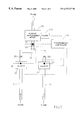
- FIG. 1 is a block schematic diagram illustrating the pressure sensor embodiment of the present invention
- FIG. 2 is a block schematic diagram illustrating the flow meter embodiment of the present invention.
- FIGS. 3A and 3B are correlation graphs illustrating potential positive displacement meter wear subsequent to installation and initial calibration of the positive displacement meter.
- the present invention provides a novel way of utilizing the sensors to achieve a desired fuel blend.
- FIG. 1 A preferred embodiment of the present invention is shown in FIG. 1 .
- the flow path illustrated emanates from two (2) underground fuel storage tanks (not shown) having dissimilar (high and low) octane ratings.
- Fluid flow inlets 10 feed into a pair of proportional flow control valves 20 , each manufactured with a pressure transducer 30 .
- Downstream of the flow control valves 20 is a manifold area 40 where the fuel is actually blended together and fed to a positive displacement meter 50 before being dispensed.
- the present invention invokes Bernoulli's principle which teaches that a variance in pressure will correlate to a linear change in flow rate.
- a computer controller 60 is programmed for a set desired fuel blend and an equivalent ratio in fluid pressure is used to obtain the desired fuel blend. For example, if a 50/50 blend between the two underground tanks is desired, controller 60 is programmed to maintain a 50/50 pressure ratio between each proportional flow control valve 20 . A pressure increase in valve “A”, for instance, will cause valve “B” to react by permitting an increase in pressure in that valve. If valve “B” is already opened to the maximum limit, then valve “A” is modulated so that its pressure is reduced. Other blend ratios are achieved by programming the controller 60 to maintain the correct pressure ratio between valves.
- An additional pressure transducer 70 can be located downstream of manifold area 40 but before positive displacement meter 50 . Controller 60 is programmed so that the pressure sensed by pressure transducer 70 is not permitted to exceed the allowed lowest pressure of either of the pressure transducers for a given flowrate. If such a condition is detected, reverse flow through one of the valves is occurring. The valves are then modulated as required in order to obtain the correct blend ratio until the pressure sensed at the transducer 70 is less than the pressure at transducers 30 .
- a pair of check valves 80 situated between flow control valves 20 and manifold area 40 serve to prevent fluid flow from reversing direction during operation of the fuel dispenser.
- a check valve is essentially a device that allows fluid to flow in one direction only.
- a third check valve 90 may be situated between manifold area 40 and positive displacement meter 50 for the purpose of keeping excess fuel which may be left in positive displacement meter 50 from going back down the flow path.
- FIG. 2 A second embodiment of the present invention is shown in FIG. 2 . It uses flow meters 100 in lieu of pressure transducers 30 .
- Flow meters 100 are installed after the proportional flow control valves 20 and are used for measuring fluid flow through each inlet 10 .
- Positive displacement meter 50 and pulser 110 provide the total fluid flow to control the system thus allowing the system to operate in a closed-loop manner.
- designated blend ratios are achieved by varying product flow through proportional flow control valves 20 . If flow meters 100 are also capable of sensing reverse fluid flow, it would allow the control software to shut the valve experiencing reverse flow.
- a pair of check valves 80 situated between flow control valves 20 and manifold area 40 serve to prevent fluid flow from reversing direction during operation of the fuel dispenser.
- a third check valve 90 may be situated between manifold area 40 and positive displacement meter 50 for the purpose of keeping excess fuel which may be left in positive displacement meter 50 from going back down the flow path.
- flow meters are viable for use in the present invention, including, but not limited to, differential pressure, micro-anemometer, venturi, turbine, capacitance, radio frequency (RF), ultrasonic, mass flow, magnetic, and acoustic.
- RF radio frequency
- Both embodiments described herein allow the performance of pressure sensors 30 or flow meters 100 to be calibrated against positive displacement meter 50 . This is achieved by having controller 60 plot the flow rate as reported by each pressure sensor 30 or flow meter 100 against the flow rate reported by positive displacement meter 50 and pulser 110 . (See, FIGS. 3A and 3B, respectively).
- the “calibration” process takes place at the factory and in the field.
- the positive displacement meter is calibrated immediately after it is manufactured.
- the initial calibration is very accurate.
- this accuracy can drift due to mechanical wear within the positive displacement meter.
- the mechanical wear actually changes the internal geometry of the positive displacement meter, so calibration needs to be performed periodically in the field.
- the calibration method requires dispensing five (5) gallons into a “prover can”.
- the prover can has a sight glass built in so the individual performing the calibration obtains a visual indication of whether the tested positive displacement meter is accurate, and if not, how inaccurate it was.
- the calibrator can then turn an adjustment wheel on the positive displacement meter to correct for any error.
- each State has an agency (typically the Department of Commerce or the Department of Agriculture) that verifies the accuracy of the fuel dispensers by using the above method. This is done when the fuel dispensers are first installed at the station and periodically afterwards (typically annually).
- the present invention takes advantage of the calibration requirement to determine the accuracy of the flow meters or pressure sensors (depending on which sensing method is used) via the high accuracy positive displacement meter.
- a blending dispenser draws fuel from two (2) underground tanks, one high octane and one low octane, and combines them in order to achieve a desired octane.
- the present invention creates an algorithm during field calibration which uses the highly accurate positive displacement meter to determine the accuracy of the flow meters or pressure sensors.
- a five (5) gallon preset is performed on the fuel dispenser.
- the controller varies the opening of the valve on one source and uses the positive displacement meter as an absolute reference while measuring the inputs from the flow or pressure sensors.
- the controller can create a table that correlates the positive displacement meter and the sensors for various flow rates.
- a “preset”, as opposed to a “fill-up”, is a fueling process for ensuring the customer receives the intended amount of fuel. The difference between the two processes is that with a fill-up, the customer physically stops the fuel flow by releasing the trigger of the nozzle. In a preset, the dispenser (not the customer) stops the fuel flow after a predetermined volume of fuel has been dispensed.
- a statistical correlation can be determined between the positive displacement meter and the flow meters or pressure sensors for different flow rates.
- the resulting blending algorithm provides higher accuracy blending by using the resulting correlation curves of FIGS. 3A and 3B.
- FIG. 3A illustrates the correlation between the positive displacement meter measurement readings and the pressure sensor (or flow meter) measurement readings at the initial calibration. This is when the positive displacement meter is at its most accurate.
- FIG. 3B illustrates the same measurements taken some time after initial calibration overlaid on the curve of FIG. 3 A.
- the statistical correlation provides the ability to detect positive displacement meter wear, which is indicated by a gradual shift in the curves. Since the fuel dispenser controller “knows” the original baseline curve, it continues to evaluate the correlation between the positive displacement meter and the sensors and compensates for positive displacement meter wear by multiplying the positive displacement meter's flow rate by a constant that reconciles the curves back into agreement. This method is viable because the flow or pressure sensors are not susceptible to wear, like the positive displacement meter.
- the correlation curve of FIG. 3B ensures that the pulser, which is the electrical device that translates the mechanical motion of the positive displacement meter into electrical information, is working properly, and has not been tampered with.
- the present invention can utilize any type of electro-mechanical flow control valve, but the preferred type is a solenoid-controlled poppet valve. This design choice is a safety consideration and insures that if power is removed from a fuel dispenser, the pressure of the gasoline in the underground piping will act to close the flow control valve(s).
Landscapes
- Engineering & Computer Science (AREA)
- Mechanical Engineering (AREA)
- Physics & Mathematics (AREA)
- General Physics & Mathematics (AREA)
- General Engineering & Computer Science (AREA)
- Automation & Control Theory (AREA)
- Mathematical Physics (AREA)
- Theoretical Computer Science (AREA)
- Fluid Mechanics (AREA)
- Measuring Volume Flow (AREA)
- Loading And Unloading Of Fuel Tanks Or Ships (AREA)
Abstract
Description
Claims (15)
Priority Applications (2)
| Application Number | Priority Date | Filing Date | Title |
|---|---|---|---|
| US09/336,501 US6227227B1 (en) | 1999-06-18 | 1999-06-18 | Single meter blending fuel dispensing system |
| US09/736,676 US6505134B2 (en) | 1999-06-18 | 2000-12-13 | Method of calibrating a single meter blending fuel dispensing system |
Applications Claiming Priority (1)
| Application Number | Priority Date | Filing Date | Title |
|---|---|---|---|
| US09/336,501 US6227227B1 (en) | 1999-06-18 | 1999-06-18 | Single meter blending fuel dispensing system |
Related Child Applications (1)
| Application Number | Title | Priority Date | Filing Date |
|---|---|---|---|
| US09/736,676 Division US6505134B2 (en) | 1999-06-18 | 2000-12-13 | Method of calibrating a single meter blending fuel dispensing system |
Publications (1)
| Publication Number | Publication Date |
|---|---|
| US6227227B1 true US6227227B1 (en) | 2001-05-08 |
Family
ID=23316392
Family Applications (2)
| Application Number | Title | Priority Date | Filing Date |
|---|---|---|---|
| US09/336,501 Expired - Fee Related US6227227B1 (en) | 1999-06-18 | 1999-06-18 | Single meter blending fuel dispensing system |
| US09/736,676 Expired - Fee Related US6505134B2 (en) | 1999-06-18 | 2000-12-13 | Method of calibrating a single meter blending fuel dispensing system |
Family Applications After (1)
| Application Number | Title | Priority Date | Filing Date |
|---|---|---|---|
| US09/736,676 Expired - Fee Related US6505134B2 (en) | 1999-06-18 | 2000-12-13 | Method of calibrating a single meter blending fuel dispensing system |
Country Status (1)
| Country | Link |
|---|---|
| US (2) | US6227227B1 (en) |
Cited By (13)
| Publication number | Priority date | Publication date | Assignee | Title |
|---|---|---|---|---|
| WO2003009165A1 (en) * | 2001-07-18 | 2003-01-30 | Lancer Partnership, Ltd. | Intelligent volumetric module for drink dispenser |
| US20060011652A1 (en) * | 2002-10-10 | 2006-01-19 | King Mark A | Membrane and solenoid actuated valve for dispensing |
| US20070108226A1 (en) * | 2005-07-08 | 2007-05-17 | Linda Sassner | Fuel dispensing unit with gas sensor |
| US20080229845A1 (en) * | 2005-12-12 | 2008-09-25 | Carrier Corporation | Flowmeter Assembly |
| US20080257429A1 (en) * | 2007-04-20 | 2008-10-23 | Gilbarco Inc. | System and method for detecting pressure variations in fuel dispensers to more accurately measure fuel delivered |
| US20090125153A1 (en) * | 2007-11-13 | 2009-05-14 | Zhou Yang | Nozzle Snap Flow Compensation |
| US20090293989A1 (en) * | 2008-06-02 | 2009-12-03 | Gilbarco Inc. | Fuel Dispenser Utilizing Pressure Sensor For Theft Detection |
| US20110277847A1 (en) * | 2008-01-14 | 2011-11-17 | Tokyo Electron Limited | Flow control method for multizone gas distribution |
| US20120132672A1 (en) * | 2010-11-30 | 2012-05-31 | Blue Nederland B.V. | Material dispensing device, material dispensing system and method for controlled dispensing of a material at an object |
| US20150068613A1 (en) * | 2013-09-12 | 2015-03-12 | Lam Research Corporation | Clutter Mass Flow Devices and Multi-Line Mass Flow Devices Incorporating The Same |
| US9802810B2 (en) | 2015-05-15 | 2017-10-31 | Gilbarco Inc. | Blending apparatus and method |
| US11993507B2 (en) | 2022-07-19 | 2024-05-28 | 7-Eleven, Inc. | Anomaly detection and controlling fuel dispensing operations using fuel volume determinations |
| US12006203B2 (en) | 2022-07-19 | 2024-06-11 | 7-Eleven, Inc. | Anomaly detection and controlling operations of fuel dispensing terminal during operations |
Families Citing this family (27)
| Publication number | Priority date | Publication date | Assignee | Title |
|---|---|---|---|---|
| US6505123B1 (en) * | 2000-07-24 | 2003-01-07 | Weatherbank, Inc. | Interactive weather advisory system |
| US6860723B2 (en) * | 2002-10-05 | 2005-03-01 | Taiwan Semiconductor Manufacturing Co., Ltd | Slurry flow control and monitor system for chemical mechanical polisher |
| US20100210986A1 (en) * | 2003-07-22 | 2010-08-19 | Sanders T Blane | Negative pressure wound treatment dressings and systems |
| US7624564B2 (en) * | 2004-07-23 | 2009-12-01 | Power Systems Mfg., Llc | Apparatus and method for providing an off-gas to a combustion system |
| US7295934B2 (en) * | 2006-02-15 | 2007-11-13 | Dresser, Inc. | Flow meter performance monitoring system |
| US20080295568A1 (en) * | 2007-06-01 | 2008-12-04 | Gilbarco Inc. | System and method for automated calibration of a fuel flow meter in a fuel dispenser |
| US8639464B2 (en) * | 2008-01-18 | 2014-01-28 | Dresser, Inc. | Flow meter diagnostic processing |
| US8986253B2 (en) | 2008-01-25 | 2015-03-24 | Tandem Diabetes Care, Inc. | Two chamber pumps and related methods |
| US8408421B2 (en) | 2008-09-16 | 2013-04-02 | Tandem Diabetes Care, Inc. | Flow regulating stopcocks and related methods |
| AU2009293019A1 (en) | 2008-09-19 | 2010-03-25 | Tandem Diabetes Care Inc. | Solute concentration measurement device and related methods |
| US9250106B2 (en) | 2009-02-27 | 2016-02-02 | Tandem Diabetes Care, Inc. | Methods and devices for determination of flow reservoir volume |
| EP2401587A2 (en) | 2009-02-27 | 2012-01-04 | Tandem Diabetes Care, Inc. | Methods and devices for determination of flow reservoir volume |
| US9211377B2 (en) | 2009-07-30 | 2015-12-15 | Tandem Diabetes Care, Inc. | Infusion pump system with disposable cartridge having pressure venting and pressure feedback |
| US8561921B1 (en) * | 2009-10-16 | 2013-10-22 | Steve C. Showman | Plural component mixing system |
| US9618376B2 (en) | 2010-07-30 | 2017-04-11 | Ecolab Usa Inc. | Apparatus, method and system for calibrating a liquid dispensing system |
| EP2631613B1 (en) * | 2010-07-30 | 2018-05-02 | Ecolab USA Inc. | Method and system for calibrating a liquid dispensing system |
| US9309898B2 (en) | 2012-02-22 | 2016-04-12 | King Nutronics Corporation | Multi-fluid precision calibration pressure source |
| US9180242B2 (en) | 2012-05-17 | 2015-11-10 | Tandem Diabetes Care, Inc. | Methods and devices for multiple fluid transfer |
| US9173998B2 (en) | 2013-03-14 | 2015-11-03 | Tandem Diabetes Care, Inc. | System and method for detecting occlusions in an infusion pump |
| JP6335645B2 (en) * | 2014-05-23 | 2018-05-30 | 三菱日立パワーシステムズ株式会社 | Combustor replacement method and gas turbine plant |
| US10378427B2 (en) | 2017-03-31 | 2019-08-13 | Saudi Arabian Oil Company | Nitrogen enriched air supply for gasoline compression ignition combustion |
| US10508017B2 (en) | 2017-10-13 | 2019-12-17 | Saudi Arabian Oil Company | Point-of-sale octane/cetane-on-demand systems for automotive engines |
| US10436126B2 (en) | 2018-01-31 | 2019-10-08 | Saudi Arabian Oil Company | Adsorption-based fuel systems for onboard cetane on-demand and octane on-demand |
| US10378462B1 (en) | 2018-01-31 | 2019-08-13 | Saudi Arabian Oil Company | Heat exchanger configuration for adsorption-based onboard octane on-demand and cetane on-demand |
| US10422288B1 (en) | 2018-03-29 | 2019-09-24 | Saudi Arabian Oil Company | Adsorbent circulation for onboard octane on-demand and cetane on-demand |
| US10408139B1 (en) | 2018-03-29 | 2019-09-10 | Saudi Arabian Oil Company | Solvent-based adsorbent regeneration for onboard octane on-demand and cetane on-demand |
| US12116265B1 (en) * | 2023-11-10 | 2024-10-15 | Phillips 66 Company | Predictive blending of oxygenated gasoline |
Citations (29)
| Publication number | Priority date | Publication date | Assignee | Title |
|---|---|---|---|---|
| US3751644A (en) | 1972-02-22 | 1973-08-07 | Sun Oil Co | Automatic blending control system |
| US3864095A (en) | 1973-12-26 | 1975-02-04 | Exxon Research Engineering Co | Anti-knock injection for in-line blending of gasoline |
| US3999959A (en) | 1974-08-12 | 1976-12-28 | Universal Oil Products Company | Motor fuel blending control system |
| US4223807A (en) | 1979-02-08 | 1980-09-23 | Dresser Industries, Inc. | Multiple product gasoline dispenser |
| US4404984A (en) | 1980-06-03 | 1983-09-20 | Jones James S | Gas-liquid mixing metering system |
| US4876653A (en) | 1987-07-15 | 1989-10-24 | Mcspadden John S | Programmable multiple blender |
| US4963745A (en) | 1989-09-01 | 1990-10-16 | Ashland Oil, Inc. | Octane measuring process and device |
| US4978029A (en) | 1989-07-03 | 1990-12-18 | Gilbarco Inc. | Multi-fuel dispenser with one nozzle per fueling position |
| US5018645A (en) | 1990-01-30 | 1991-05-28 | Zinsmeyer Herbert G | Automotive fluids dispensing and blending system |
| US5029100A (en) * | 1989-12-15 | 1991-07-02 | Gilbarco Inc. | Blender system for fuel dispenser |
| US5038971A (en) | 1989-09-29 | 1991-08-13 | Tokheim Corporation | Variable blending dispenser |
| US5125533A (en) | 1989-09-29 | 1992-06-30 | Tokheim Corporation | Variable blending dispenser |
| US5139045A (en) | 1991-12-16 | 1992-08-18 | Ensign Petroleum Equipment Co. Inc. | System for dispensing a fuel mixture |
| US5203384A (en) | 1990-08-15 | 1993-04-20 | Dresser Industries, Inc. | Combination casting for a blending dispenser |
| US5223714A (en) | 1991-11-26 | 1993-06-29 | Ashland Oil, Inc. | Process for predicting properties of multi-component fluid blends |
| US5225679A (en) | 1992-01-24 | 1993-07-06 | Boston Advanced Technologies, Inc. | Methods and apparatus for determining hydrocarbon fuel properties |
| US5257720A (en) | 1991-12-20 | 1993-11-02 | Gasboy International, Inc. | Gasoline blending and dispensing system |
| US5412581A (en) | 1992-11-05 | 1995-05-02 | Marathon Oil Company | Method for measuring physical properties of hydrocarbons |
| US5447062A (en) | 1991-12-19 | 1995-09-05 | Tankanlagen Salzkotten Gmbh | Apparatus for measuring quantities of liquid in gasoline pumps of motor vehicle filling stations |
| US5469830A (en) * | 1995-02-24 | 1995-11-28 | The Cessna Aircraft Company | Fuel blending system method and apparatus |
| US5569922A (en) | 1995-07-26 | 1996-10-29 | Boston Advanced Technologies, Inc. | Portable fuel analyzer for the diagnosis of fuel-related problems on-site at the vehicle service bay |
| US5606130A (en) | 1994-03-25 | 1997-02-25 | The Regents Of The University Of California | Method for determining the octane rating of gasoline samples by observing corresponding acoustic resonances therein |
| US5630528A (en) | 1995-01-27 | 1997-05-20 | Gilbarco, Inc. | Method and apparatus for metering and dispensing fluid, particulary fuel |
| US5706871A (en) | 1995-08-15 | 1998-01-13 | Dresser Industries, Inc. | Fluid control apparatus and method |
| US5921263A (en) | 1997-07-23 | 1999-07-13 | Dresser Industries, Inc. | Fuel dispensing system using a common meter and octane sensing |
| GB2333508A (en) | 1998-01-26 | 1999-07-28 | Dresser Ind | Fuel dispensing system and method using octane sensing and display |
| US5956254A (en) * | 1996-10-10 | 1999-09-21 | Tokheim Corporation | Octane sensitive dispenser blending system |
| US5979705A (en) | 1998-05-29 | 1999-11-09 | Gilbarco Inc. | Fuel blending using blend component octane levels |
| US6065638A (en) * | 1998-05-29 | 2000-05-23 | Gilbarco Inc. | Real time blending apparatus and method |
Family Cites Families (12)
| Publication number | Priority date | Publication date | Assignee | Title |
|---|---|---|---|---|
| GB205283A (en) * | 1922-08-30 | 1923-10-18 | William Henry Sumbling | Improvements in fluid-tight joints |
| US3822056A (en) * | 1972-03-31 | 1974-07-02 | R Hawes | Method and means for adding small measured quantities of selected materials to a large capacity material-mixing plant |
| US3939688A (en) * | 1974-09-16 | 1976-02-24 | Edge Saw Manufacturing Company | Volumetric calibration |
| US3999459A (en) * | 1975-03-14 | 1976-12-28 | Gottschall Tool & Die Co. | Mine roof bolt anchor construction and method of making the same |
| US4392508A (en) * | 1981-04-15 | 1983-07-12 | Ryco Graphic Manufacturing, Inc. | Proportional mixing system with water motor drive |
| US4809909A (en) * | 1985-06-13 | 1989-03-07 | Glas-Craft, Inc. | Plural component application system |
| US4821761A (en) * | 1987-05-15 | 1989-04-18 | Baxter Travenol Laboratories, Inc. | Closed loop pump control system |
| DE3808577A1 (en) * | 1987-08-20 | 1989-03-02 | Tecalemit Gmbh Deutsche | Delivery device for mineral oil products |
| DE3924123C2 (en) * | 1989-07-20 | 1994-01-27 | Draegerwerk Ag | Device for generating and metering a gas mixture |
| GB9224304D0 (en) * | 1992-11-19 | 1993-01-06 | Secr Defence | Calibration systems |
| US5540251A (en) * | 1994-02-01 | 1996-07-30 | Mayeaux; Paul H. | Precision gas blender |
| US5661225A (en) * | 1996-09-12 | 1997-08-26 | Air Products And Chemicals, Inc. | Dynamic dilution system |
-
1999
- 1999-06-18 US US09/336,501 patent/US6227227B1/en not_active Expired - Fee Related
-
2000
- 2000-12-13 US US09/736,676 patent/US6505134B2/en not_active Expired - Fee Related
Patent Citations (31)
| Publication number | Priority date | Publication date | Assignee | Title |
|---|---|---|---|---|
| US3751644A (en) | 1972-02-22 | 1973-08-07 | Sun Oil Co | Automatic blending control system |
| US3864095A (en) | 1973-12-26 | 1975-02-04 | Exxon Research Engineering Co | Anti-knock injection for in-line blending of gasoline |
| US3999959A (en) | 1974-08-12 | 1976-12-28 | Universal Oil Products Company | Motor fuel blending control system |
| US4223807A (en) | 1979-02-08 | 1980-09-23 | Dresser Industries, Inc. | Multiple product gasoline dispenser |
| US4404984A (en) | 1980-06-03 | 1983-09-20 | Jones James S | Gas-liquid mixing metering system |
| US4876653A (en) | 1987-07-15 | 1989-10-24 | Mcspadden John S | Programmable multiple blender |
| US4978029A (en) | 1989-07-03 | 1990-12-18 | Gilbarco Inc. | Multi-fuel dispenser with one nozzle per fueling position |
| US4963745A (en) | 1989-09-01 | 1990-10-16 | Ashland Oil, Inc. | Octane measuring process and device |
| US5038971A (en) | 1989-09-29 | 1991-08-13 | Tokheim Corporation | Variable blending dispenser |
| US5125533A (en) | 1989-09-29 | 1992-06-30 | Tokheim Corporation | Variable blending dispenser |
| US5029100A (en) * | 1989-12-15 | 1991-07-02 | Gilbarco Inc. | Blender system for fuel dispenser |
| US5018645A (en) | 1990-01-30 | 1991-05-28 | Zinsmeyer Herbert G | Automotive fluids dispensing and blending system |
| US5203384A (en) | 1990-08-15 | 1993-04-20 | Dresser Industries, Inc. | Combination casting for a blending dispenser |
| US5223714A (en) | 1991-11-26 | 1993-06-29 | Ashland Oil, Inc. | Process for predicting properties of multi-component fluid blends |
| US5139045A (en) | 1991-12-16 | 1992-08-18 | Ensign Petroleum Equipment Co. Inc. | System for dispensing a fuel mixture |
| EP0572621B1 (en) | 1991-12-19 | 1996-09-18 | Tankanlagen Salzkotten Gmbh | Device for measuring the amount of liquid in the gasoline pumps of motor vehicle service stations |
| US5447062A (en) | 1991-12-19 | 1995-09-05 | Tankanlagen Salzkotten Gmbh | Apparatus for measuring quantities of liquid in gasoline pumps of motor vehicle filling stations |
| US5257720A (en) | 1991-12-20 | 1993-11-02 | Gasboy International, Inc. | Gasoline blending and dispensing system |
| US5225679A (en) | 1992-01-24 | 1993-07-06 | Boston Advanced Technologies, Inc. | Methods and apparatus for determining hydrocarbon fuel properties |
| US5412581A (en) | 1992-11-05 | 1995-05-02 | Marathon Oil Company | Method for measuring physical properties of hydrocarbons |
| US5606130A (en) | 1994-03-25 | 1997-02-25 | The Regents Of The University Of California | Method for determining the octane rating of gasoline samples by observing corresponding acoustic resonances therein |
| US5630528A (en) | 1995-01-27 | 1997-05-20 | Gilbarco, Inc. | Method and apparatus for metering and dispensing fluid, particulary fuel |
| US5469830A (en) * | 1995-02-24 | 1995-11-28 | The Cessna Aircraft Company | Fuel blending system method and apparatus |
| US5569922A (en) | 1995-07-26 | 1996-10-29 | Boston Advanced Technologies, Inc. | Portable fuel analyzer for the diagnosis of fuel-related problems on-site at the vehicle service bay |
| US5706871A (en) | 1995-08-15 | 1998-01-13 | Dresser Industries, Inc. | Fluid control apparatus and method |
| US5956254A (en) * | 1996-10-10 | 1999-09-21 | Tokheim Corporation | Octane sensitive dispenser blending system |
| US5921263A (en) | 1997-07-23 | 1999-07-13 | Dresser Industries, Inc. | Fuel dispensing system using a common meter and octane sensing |
| US6006775A (en) * | 1997-07-23 | 1999-12-28 | Dresser Industries, Inc. | Fuel dispensing system using a common meter and octane sensing |
| GB2333508A (en) | 1998-01-26 | 1999-07-28 | Dresser Ind | Fuel dispensing system and method using octane sensing and display |
| US5979705A (en) | 1998-05-29 | 1999-11-09 | Gilbarco Inc. | Fuel blending using blend component octane levels |
| US6065638A (en) * | 1998-05-29 | 2000-05-23 | Gilbarco Inc. | Real time blending apparatus and method |
Cited By (26)
| Publication number | Priority date | Publication date | Assignee | Title |
|---|---|---|---|---|
| WO2003009165A1 (en) * | 2001-07-18 | 2003-01-30 | Lancer Partnership, Ltd. | Intelligent volumetric module for drink dispenser |
| US20060011652A1 (en) * | 2002-10-10 | 2006-01-19 | King Mark A | Membrane and solenoid actuated valve for dispensing |
| US7296708B2 (en) * | 2002-10-10 | 2007-11-20 | Graco Minnesota Inc. | Membrane and solenoid actuated valve for dispensing |
| US7963423B2 (en) * | 2005-07-08 | 2011-06-21 | Dresser, Inc. | Fuel dispensing unit with gas sensor |
| US20070108226A1 (en) * | 2005-07-08 | 2007-05-17 | Linda Sassner | Fuel dispensing unit with gas sensor |
| US20080229845A1 (en) * | 2005-12-12 | 2008-09-25 | Carrier Corporation | Flowmeter Assembly |
| US8424719B2 (en) | 2005-12-12 | 2013-04-23 | Carrier Corporation | Flowmeter assembly |
| US8025184B2 (en) * | 2005-12-12 | 2011-09-27 | Carrier Corporation | Flowmeter assembly |
| US20080257429A1 (en) * | 2007-04-20 | 2008-10-23 | Gilbarco Inc. | System and method for detecting pressure variations in fuel dispensers to more accurately measure fuel delivered |
| US7681460B2 (en) * | 2007-04-20 | 2010-03-23 | Gilbarco Inc. | System and method for detecting pressure variations in fuel dispensers to more accurately measure fuel delivered |
| US20100172767A1 (en) * | 2007-04-20 | 2010-07-08 | Gilbarco Inc. | System and method for detecting pressure variations in fuel dispensers to more accurately measure fuel delivered |
| US7954386B2 (en) | 2007-04-20 | 2011-06-07 | Gilbarco Inc. | System and method for detecting pressure variations in fuel dispensers to more accurately measure fuel delivered |
| US20090125153A1 (en) * | 2007-11-13 | 2009-05-14 | Zhou Yang | Nozzle Snap Flow Compensation |
| US7725271B2 (en) | 2007-11-13 | 2010-05-25 | Gilbarco Inc. | Nozzle snap flow compensation |
| US20110277847A1 (en) * | 2008-01-14 | 2011-11-17 | Tokyo Electron Limited | Flow control method for multizone gas distribution |
| US8464741B2 (en) * | 2008-01-14 | 2013-06-18 | Tokyo Electron Limited | Flow control method for multizone gas distribution |
| US8042376B2 (en) | 2008-06-02 | 2011-10-25 | Gilbarco Inc. | Fuel dispenser utilizing pressure sensor for theft detection |
| US20090293989A1 (en) * | 2008-06-02 | 2009-12-03 | Gilbarco Inc. | Fuel Dispenser Utilizing Pressure Sensor For Theft Detection |
| US20120132672A1 (en) * | 2010-11-30 | 2012-05-31 | Blue Nederland B.V. | Material dispensing device, material dispensing system and method for controlled dispensing of a material at an object |
| US20150068613A1 (en) * | 2013-09-12 | 2015-03-12 | Lam Research Corporation | Clutter Mass Flow Devices and Multi-Line Mass Flow Devices Incorporating The Same |
| US9335768B2 (en) * | 2013-09-12 | 2016-05-10 | Lam Research Corporation | Cluster mass flow devices and multi-line mass flow devices incorporating the same |
| US9802810B2 (en) | 2015-05-15 | 2017-10-31 | Gilbarco Inc. | Blending apparatus and method |
| US10870572B2 (en) | 2015-05-15 | 2020-12-22 | Gilbarco Inc. | Blending apparatus and method |
| US11339049B2 (en) | 2015-05-15 | 2022-05-24 | Gilbarco Inc. | Blending apparatus and method |
| US11993507B2 (en) | 2022-07-19 | 2024-05-28 | 7-Eleven, Inc. | Anomaly detection and controlling fuel dispensing operations using fuel volume determinations |
| US12006203B2 (en) | 2022-07-19 | 2024-06-11 | 7-Eleven, Inc. | Anomaly detection and controlling operations of fuel dispensing terminal during operations |
Also Published As
| Publication number | Publication date |
|---|---|
| US20010000282A1 (en) | 2001-04-19 |
| US6505134B2 (en) | 2003-01-07 |
Similar Documents
| Publication | Publication Date | Title |
|---|---|---|
| US6227227B1 (en) | Single meter blending fuel dispensing system | |
| US11339049B2 (en) | Blending apparatus and method | |
| CN100552588C (en) | The regulator flow measurement device | |
| CN102483344B (en) | Upstream volume mass flow verification system and method | |
| US6065638A (en) | Real time blending apparatus and method | |
| US6854342B2 (en) | Increased sensitivity for turbine flow meter | |
| US7111520B2 (en) | Increased sensitivity for liquid meter | |
| US20110094287A1 (en) | System and method for automated calibration of a fuel flow meter in a fuel dispenser | |
| US7725271B2 (en) | Nozzle snap flow compensation | |
| US5125533A (en) | Variable blending dispenser | |
| CA2025450A1 (en) | Variable blending dispenser | |
| US7954386B2 (en) | System and method for detecting pressure variations in fuel dispensers to more accurately measure fuel delivered | |
| US6112134A (en) | Single meter octane blending apparatus | |
| US6253779B1 (en) | Blending system and method using an auxiliary measuring device | |
| EP3954974B1 (en) | Gas flowmeter having inline calibrating | |
| EP1054834B1 (en) | Fluid system and method utilizing a master meter and blend ratio meter | |
| US6739205B2 (en) | Controller for monitoring fluid flow volume | |
| US5629863A (en) | Additive blending controller | |
| US6782763B2 (en) | Propane measurement using a coriolis flowmeter | |
| US5421188A (en) | Proving means and method | |
| JPS6152409B2 (en) | ||
| GB2295896A (en) | Calibration of flowmeters | |
| EP0961190A1 (en) | Fuel blending apparatus using octane levels | |
| WO2020235423A1 (en) | Gas safety device and gas safety system | |
| WO2001016566A1 (en) | Multiple orifice ultrasonic meter in a multiproduct fuel dispenser using ultrasonic metering |
Legal Events
| Date | Code | Title | Description |
|---|---|---|---|
| AS | Assignment |
Owner name: GILBARCO, INC., NORTH CAROLINA Free format text: ASSIGNMENT OF ASSIGNORS INTEREST;ASSIGNORS:POLESHUK, EDWARD S.;LONG, JOSEPH D.;REEL/FRAME:010064/0108 Effective date: 19990617 |
|
| AS | Assignment |
Owner name: MARCONI COMMERCE SYSTEMS INC., NORTH CAROLINA Free format text: CHANGE OF NAME;ASSIGNOR:GILBARCO INC.;REEL/FRAME:010654/0957 Effective date: 19991206 |
|
| AS | Assignment |
Owner name: GILBARCO INC., NORTH CAROLINA Free format text: CHANGE OF NAME;ASSIGNOR:MARCONI COMMERCE SYSTEMS INC.;REEL/FRAME:013177/0660 Effective date: 20020215 |
|
| CC | Certificate of correction | ||
| FPAY | Fee payment |
Year of fee payment: 4 |
|
| FEPP | Fee payment procedure |
Free format text: PAYER NUMBER DE-ASSIGNED (ORIGINAL EVENT CODE: RMPN); ENTITY STATUS OF PATENT OWNER: LARGE ENTITY Free format text: PAYOR NUMBER ASSIGNED (ORIGINAL EVENT CODE: ASPN); ENTITY STATUS OF PATENT OWNER: LARGE ENTITY |
|
| REMI | Maintenance fee reminder mailed | ||
| LAPS | Lapse for failure to pay maintenance fees | ||
| STCH | Information on status: patent discontinuation |
Free format text: PATENT EXPIRED DUE TO NONPAYMENT OF MAINTENANCE FEES UNDER 37 CFR 1.362 |
|
| FP | Lapsed due to failure to pay maintenance fee |
Effective date: 20090508 |