US6157389A - Method for reducing the size of an image - Google Patents
Method for reducing the size of an image Download PDFInfo
- Publication number
- US6157389A US6157389A US08/340,003 US34000394A US6157389A US 6157389 A US6157389 A US 6157389A US 34000394 A US34000394 A US 34000394A US 6157389 A US6157389 A US 6157389A
- Authority
- US
- United States
- Prior art keywords
- image
- subimage
- entries
- bands
- band
- Prior art date
- Legal status (The legal status is an assumption and is not a legal conclusion. Google has not performed a legal analysis and makes no representation as to the accuracy of the status listed.)
- Expired - Lifetime
Links
- 238000000034 method Methods 0.000 title claims abstract description 105
- 238000012545 processing Methods 0.000 claims abstract description 46
- 238000012217 deletion Methods 0.000 claims description 60
- 230000037430 deletion Effects 0.000 claims description 60
- 230000007812 deficiency Effects 0.000 claims description 11
- 238000010586 diagram Methods 0.000 description 18
- 238000007906 compression Methods 0.000 description 13
- 238000009825 accumulation Methods 0.000 description 11
- 230000006835 compression Effects 0.000 description 9
- 238000012360 testing method Methods 0.000 description 9
- 239000007787 solid Substances 0.000 description 8
- 230000000694 effects Effects 0.000 description 4
- 230000000007 visual effect Effects 0.000 description 4
- 238000003491 array Methods 0.000 description 3
- 238000004458 analytical method Methods 0.000 description 2
- 238000011156 evaluation Methods 0.000 description 2
- 238000013519 translation Methods 0.000 description 2
- 235000008429 bread Nutrition 0.000 description 1
- 239000003086 colorant Substances 0.000 description 1
- 230000000593 degrading effect Effects 0.000 description 1
- 238000004321 preservation Methods 0.000 description 1
- 238000010008 shearing Methods 0.000 description 1
- 238000005549 size reduction Methods 0.000 description 1
Images


Classifications
-
- G—PHYSICS
- G06—COMPUTING; CALCULATING OR COUNTING
- G06T—IMAGE DATA PROCESSING OR GENERATION, IN GENERAL
- G06T3/00—Geometric image transformations in the plane of the image
- G06T3/04—Context-preserving transformations, e.g. by using an importance map
Definitions
- the present invention relates to a method for processing binary objects, such as bitmaps, representing visual images, such as screen or scanned images, to compress them in the sense of reducing the size of the image represented by that binary object.
- binary objects such as bitmaps, representing visual images, such as screen or scanned images
- an image represented by a binary object For example, it may be desired to reduce the display size of an image representing textual data. Or it may be desired to represent a document as an icon by compressing the actual image of such a document (or first page of the document) to icon size. In both of these cases, it is desirable to maintain to the maximum extent possible the details and legibility of the compressed image formed from the full size image.
- a visual image may be represented as an array of r rows by c columns of pixels (picture elements).
- a known method for compressing such image representative data to reduce the size of the image is decimation of the image representative data, i.e. the removal from the image array of regularly spaced rows and/or columns of pixels. For example, to reduce the size of an image by 50% horizontally and vertically, every other row of pixels is deleted, and every other pixel in the remaining rows is also deleted. Decimation is simple and fast. However, because the image structure is disregarded, details and legibility of the resulting compressed image are degraded.
- the inventor has realized that often images contain areas from which image information could be omitted without degrading the detail or legibility of the image. For example, large swaths (either adjacent rows or adjacent columns) of a solid color (e.g. white or black) represent such image information. Such areas will be called blank areas in the remainder of this application.
- the inventor has further realized that by preferentially deleting pixels from such areas, the size of an image may be reduced, while maintaining the details and legibility of the original image. Only when blank areas are no longer available, but further size reduction is required, will the other areas, called occupied areas in the remainder of this application, be reduced in size.
- a computer system is operated to reduce the size of an image according to a method comprising the following steps. First, data representing an image, a size of that image, and a desired size for the compressed image is received by the system. If processing of the image is finished, then data representing the compressed image is emitted, otherwise the image is partitioned into a plurality of subimages, each specified by data including data representing the subimage, a size of the subimage, and a desired size for a corresponding compressed subimage. Then the above steps are repeated for each subimage.
- FIG. 1 is a block diagram of a computer system on which the compression method according to the present invention may be practiced
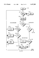
- FIG. 2 is a flow diagram illustrating a method of compressing an image in accordance with the present invention
- FIG. 3 is a more detailed flow diagram illustrating a portion of the method of compressing an image illustrated in FIG. 2;
- FIG. 4, FIG. 8 and FIG. 12 are more detailed flow diagrams illustrating portions of the method of compressing an image illustrated in FIG. 3;
- FIG. 5, FIG. 7, FIG. 9, FIG. 10 and FIG. 11 are storage diagrams illustrating rasterized image arrays useful in understanding the compression process according to the present invention
- FIG. 6 is a table of information generated and used by the compression process according to the present invention.
- FIG. 13 and FIG. 14 are diagrams illustrating corresponding source and destination image arrays, respectively, illustrating the source image before, and the destination image after compression, according to the present invention.
- FIG. 1 is a block diagram of a computer system 60 on which the compression method according to the present invention may be practiced.
- a central processing unit (CPU) 62, a read/write memory (RAM) 64 and a read only memory (ROM) 66 are coupled together in a known manner via a system bus 68.
- a display device 82 is coupled to the system bus 68 through a display adapter 80, and a floppy disk storage system 72 and hard disk storage system 74 are both also coupled to the bus 68, also in a known manner.
- Other elements may also be included in the computer system 60, such as keyboards, and other storage and/or input/output devices.
- the CPU 62 executes programs stored in the RAM 64 and/or ROM 66, and operates to read data from the RAM 64, the ROM 66, the floppy disk 72, the hard disk 74 and/or other input devices (not shown); to process the data; and to write data to the RAM 64, the display adapter 80, the floppy disk 72, the hard disk 74 and/or other output devices (not shown).
- graphical images are displayed on the display device 82, under the control of the display adapter 80.
- data representing the images to be displayed on the display device 82 is stored in the RAM 64.
- the display adapter 80 retrieves this data, and controls the operation of the display device 82 to produce the image represented by that data on the display device 82.
- An image of a page 20 is illustrated on display device 82.
- the image 20 may, for example, consist of lines of text, each line consisting of several words, each word consisting of several letters.
- Data representing this page image 20 is stored in rasterized form in RAM 64 as an array of bits having r rows and c columns, in a known manner. Each bit in the array represents a corresponding pixel in the raster, in which a black pixel is represented by a bit having a logical ⁇ 1 ⁇ value and a white pixel is represented by a bit having a logical ⁇ 0 ⁇ value.
- Also illustrated on the display device 82 is a reduced-sized image 20' of the page image 20.
- the CPU executes a program, described in more detail below, which takes as input image representative data which includes two components.
- the first component is the image array stored in the RAM 64, described above.
- the second component called the image specification in the remainder of this application, is data specifying: the location and boundaries in the image array of the image to be compressed (e.g. a top row, bottom row, left-hand column and right-hand column of the portion of the data array containing the data representing the image to be compressed); the respective numbers of pixels to be deleted from each row and each column of the specified image to generate a compressed image having the desired size; and other data to be described in more detail below.
- the program produces data from which the compressed image may be constructed.
- an image stored in one image array is visually compressed to generate a compressed image stored in a second image array, similar to the source image array and referred to below as the destination image array.
- included in the image specification data is a location (e.g. a top row and left-hand column) in the destination array at which the data representing the compressed image is to be placed.
- a color image could also be compressed using the method according to the present invention.
- a color image could be translated into a similar array of bits, each bit representing a pixel, in which a pixel of a background color is represented by a bit having a logical ⁇ 0 ⁇ value, and a pixel of any other color is represented by a bit having a logical ⁇ 1 ⁇ value.
- This bit array is processed in the same manner as the array described above representing a black and white image to produce the reduced size image. Further, as described above, during the compression process, the image may be divided into subimages.
- a different color may be designated as the background color for each respective subimage during the translation of that subimage into a corresponding array of bits.
- the translation of the color image into a bit array is for the purposes of visual compression only. A color image compressed in this manner will remain a color image having the same colors as the original.
- FIG. 2 is a flow diagram illustrating a method of compressing an image in accordance with the present invention.
- the processing illustrated in FIG. 2 takes the portion of the source image array defined by the image specification data, consisting of r rows and c columns of pixels, and deletes a number of pixels defined in the image specification data from each column of pixels such that the compressed image has r d rows, and a number of pixels defined in the image specification data from each row of pixels such that the compressed image has c d columns of pixels.
- the method illustrated in FIG. 2 begins at step 100, where any required initializations are performed.
- step 102 the image specification data representing the image to be compressed (described above) is selected.
- a pointer may be set to point to such data, or the data may be retrieved from the top of a stack, onto which it was pushed during the initialization step 100.
- this image specification data is retrieved from the selected location, e.g. the image specification data is popped off the top of the stack.
- the image specification data, thus retrieved, is first analyzed to determine whether the image may be considered finished. An image is considered finished when only relatively trivial processing remains to be performed. Steps 106 to 116 perform this analysis and also the relatively trivial processing required, if the retrieved image is considered finished. If the image is not considered finished, then further processing, described in detail below, is performed.
- the size of the image being processed is compared to the desired size for the compressed image, e.g. the respective numbers of pixels to be deleted from the rows and columns of the image are checked. If no pixels are to be deleted from either rows or columns, then the size of the image being processed is the desired size of the compressed image, no further processing of the image is required, and data representing the image is emitted in step 108 to subsequent processing (not shown).
- the emitted data may, for example, include image array data in the source image array representing the compressed image, and corresponding image specification data including the size of the compressed image, and a location in the destination image array for this image array data.
- Subsequent processing may, for example, assemble the compressed image by transferring the image array data to the specified location in the destination array, and display the assembled compressed image on the display device 82 (of FIG. 1) or store it in a mass storage device such as the floppy disk 72 or hard disk 74.
- the source image array data representing the image being processed is checked to determine whether it represents a blank area, i.e. a solid color, as described above.
- One method for determining if the image array data representing the image being processed represents a blank area is to analyze each pixel representative bit in the source image array in a manner to be described in more detail below. If all the bits have the same logical value, then the image is either solid black (all ⁇ 1 ⁇ bits) or solid white (all ⁇ 0 ⁇ bits). In either case, the image has no visual detail, either vertically or horizontally, and the required pixels may be deleted from rows and columns anywhere within the image, which is a relatively trivial process.
- step 110 If in step 110 it is determined that the image is blank, then the required data is deleted in some manner in step 112. For example, rows could be deleted from the bottom of the image, and columns could be deleted from the right-hand side of the image. Data representing the resulting image, which has the desired size, is then emitted in step 108, as described above.
- the size of the image being processed is compared to a threshold size.
- the area of the image (r ⁇ c) may be compared to a number A, representing a threshold area; or the dimensions of the image, i.e. r and c, may be respectively compared to a number t, representing a threshold length.
- a and t may be changed dynamically during the processing illustrated in FIG. 2, and their values may be related.
- step 116 Data representing the decimated image, which has the desired size, is emitted in step 108, as described above.
- the image being processed is not capable of being processed in steps 106 to 116, as described above, then it is subdivided into smaller images, sometimes termed subimages in the remainder of this application, which will all be subsequently processed in a similar manner.
- the image being processed is analyzed, in a manner to be described in more detail below, to divide it into two or more subimages.
- Image specification data representing each resulting subimage including: the location and size in the source image array of the subimage, the respective number of pixels to be deleted from each row and column of the subimage, the location in the destination image array (which is also stored separately) of the compressed subimage to be generated from this subimage, and other data described below; is then stored for future retrieval. For example, this data may be pushed atop a stack.
- Step 122 is reached either after data representing a compressed image has been emitted in step 108, or after the image has been divided into subimages in step 118, and image specification data for each respective subimage has been pushed on the stack.
- step 122 a check is made to determine whether any subimages remain to be processed. For example, if subimage specification data is kept in entries on a stack, step 122 checks to determine if the stack has any entries remaining in it. If not, then the process ends in step 126. Otherwise, in step 124, the image specification data representing the next subimage to process is selected. For example, the next subimage entry may be popped off the top of the stack.
- This subimage specification data is then processed by the steps 104-118 until it either is successfully compressed in steps 106-116, or it is divided into further subimages in step 118. This loop continues until all the subimages have been successfully compressed in some manner, and none remain to be processed.
- FIG. 3 is a more detailed.flow diagram illustrating the step 118 (of FIG. 2) of dividing the image being processed into subimages.
- the process of step 118 begins in step 202 in which initial data is generated, and any required initializations are performed. Specifically, horizontal and vertical profiles of the foreground (black) pixels in the image being processed are prepared, in a manner described below, in step 202.
- FIG. 5 is a storage diagram of a source image array of bits representing a rasterized image which is useful in understanding the process illustrated in FIG. 3.
- a raster 10 pixels high and 33 pixels wide is illustrated, i.e. the image array of bits has 10 rows and 33 columns.
- Bits in the image array representing pixels are illustrated as small squares; bits representing foreground, or black, pixels are illustrated as crosses within the square, and bits representing background, or white pixels are illustrated as blank squares.
- the array illustrated in FIG. 5 represents an image of an "I” and a "1", followed by some blank space, and concluding with a "t". In the following description, it is desired to compress this image by 19 columns and three rows by deleting 19 pixels from each row of pixels, and 3 pixels from each column of pixels.
- a vertical profile is made of the columns of the source image array by counting the number of foreground, or black, pixels in each column.
- the vertical profile VP is illustrated by the numbers across the top of the source image array illustrated in FIG. 5. In the three leftmost columns, there are no foreground pixels, so the counts in the vertical profile are 0. In the fourth column, there are two foreground pixels (illustrated as crosses in their blocks), so the count is 2. In the fifth column, there are four foreground pixels, so the count is 4, and so forth.
- a horizontal profile is made of the rows of the source image array by counting the number of foreground pixels in each row.
- the horizontal profile HP is illustrated by the numbers down the right-hand side of the illustrated source image array in FIG. 5. The topmost row has no foreground pixels, so the count is 0.
- the second row contains six foreground pixels, so the count is 6.
- the third row also contains six foreground pixels, so the count is 6, and so forth.
- the vertical VP and horizontal HP profiles, illustrated in FIG. 5 are further processed in step 202 (of FIG. 3) to determine the width of the widest blank slice (like a slice of bread) or the height of the tallest blank layer (like a layer of a cake) within the image.
- Blank slices or layers forming a margin or lying on the periphery of the image are not considered to be ⁇ within ⁇ the image, as that term is used in this context, and are ignored in this processing.
- the vertical profile VP there are two blank slices within the image: between the "I" and the "1" being 6 columns wide, and between the "1" and the "t” being 11 columns wide.
- the width of the widest slice within the image thus, is 11.
- the horizontal profile HP there are no blank layers within the image--the top and bottom rows not being considered to be within the image, as described above.
- the height of the tallest layer within the image thus, is 0.
- the width of the widest blank slice and height of the tallest blank layer could be accumulated simultaneously with the counting of the foreground pixels in the columns and rows when profiling the image.
- the vertical VP and horizontal HP profiles, and the width of the widest blank slice and height of the tallest blank layer within the image will be used in steps described below.
- step 204 a decision is made whether to divide the image vertically into two or more slices or horizontally into two or more layers. This decision is based on the width of the widest blank slice and the height of the tallest blank layer within the image, the aspect ratio of the image, and the respective numbers of pixels to be deleted from each of the rows and columns of the image.
- FIG. 4 is a more detailed flow diagram illustrating the process of step 204 (of FIG. 3) of deciding whether to divide the image into slices or layers.
- FIG. 4 illustrates a series of tests based upon the above criteria. One result of each test may be a decision to divide the image being processed into either slices or layers.
- every test to determine whether to divide the image into layers contains an additional test to determine whether any pixels are to be deleted from the columns in the image. If no such pixels are to be deleted, then there is no need to divide the image into layers and the test fails.
- every test to determine whether to divide the image into slices contains an additional test to determine whether any pixels are to be deleted from the rows of the image. If no such pixels are to be deleted from rows of the image, then there is no need to divide the image into slices and the test fails.
- step 302 begins in step 302, in which data representing the various criteria discussed above is gathered, and preliminary calculations are performed.
- step 304 if the width of the image (number of columns c) is greater than four times the height (the number of rows r), i.e. c>4r, the image is termed very flat. If the image is very flat, and there are pixels to delete from rows of the image, then the decision is made to cut the image into slices in step 306.
- step 308 if the height of the image is greater than four times the width, i.e. r>4c, the image is termed very tall. If the image is very tall, and there are pixels to delete from the columns of the image, then the decision is made to divide the image into layers in step 310.
- the width of the widest blank slice within the image is compared to the height of the tallest blank layer within the image.
- step 312 if the width of the widest blank slice is greater than the height of the tallest blank layer, and there are pixels to be deleted from rows of the image, then the image is divided into slices in step 306.
- step 314 if the height of the tallest blank layer is greater than the width of the widest blank slice, and there are pixels to be deleted from the columns of the image, then the image is divided into layers in step 306.
- step 316 if the width of the image is greater than twice the height, i.e. c>2r, the image is termed flat. If the image is flat, and there are pixels to delete from the rows of the image, then the decision is made to cut the image into slices in step 306.
- step 318 if the height of the image is greater than twice the width, i.e. r>2c, the image is termed tall. If the image is tall, and there are pixels to delete from the columns of the image, then the decision is made to divide the image into layers in step 310.
- steps 320 and 322 both the aspect ratio of the image and the presence of blank slices or layers within the image being partitioned is tested.
- the presence of blank slices and layers within the image is indicated by a non-zero value for the width of the widest blank slice and the height of the tallest blank layer, respectively.
- step 320 if the width of the image is greater than the height, i.e. c>r, the image is termed somewhat flat. If the image is somewhat flat, and there is a blank slice within the image, and there are pixels to delete from the rows of the image, then the decision is made to cut the image into slices in step 306.
- the height of the image is greater than the width, i.e. r>c, the image is termed somewhat tall. If the image is somewhat tall, and there is a blank layer within the image, and there are pixels to delete from the columns of the image, then the decision is made to divide the image into layers in step 310.
- steps 324 and 326 only the presence of blank slices or layers within the image boeing divided is tested.
- step 324 if there is a blank slice within the image, and there are pixels to delete from the rows of the image, then the decision is made to cut the image into slices in step 306.
- step 326 if there is a blank layer within the image, and there are pixels to delete from the columns of the image, then the decision is made to divide the image into layers in step 310.
- steps 328 and 330 only the aspect ratio of the image being divided is tested.
- step 328 if the image is somewhat flat, and there are pixels to delete from the rows of the image, then the decision is made to cut the image into slices in step 306.
- step 330 if the image is somewhat tall, and there are pixels to delete from the columns of the image, then the decision is made to divide the image into layers in step 310.
- step 332 if there are pixels to be deleted from rows of the image, then a decision is made to divide the image into slices in step 306. If no pixels are to be deleted from rows of the image, then (by default), there are pixels to be deleted from columns of the image, and a decision is made to divide the image into layers in step 310.
- the width c of the image is 33 columns, and the height r is 10 rows. As described above, 3 pixels are to be deleted from each column, and 19 pixels are to be deleted from each row of the image.
- the width of the widest blank slice within the image is 11, and the height of the tallest blank layer is 0.
- the image being divided is neither very tall nor very flat (steps 304 and 308). However, the width (11) of the widest blank slice within the image is larger than the height (0) of the tallest blank layer.
- a decision is made to divide the image into slices in step 312.
- the overall decision process of FIG. 4 is arranged so as sometimes to obviate the need for constructing the horizontal profile HP or the vertical profile VP, or both, each of which is a time consuming process.
- step 206 an appropriate profile of the image is processed to divide the image into alternating blank and occupied bands. If the image is being divided into slices, then the vertical profile VP is processed, and if the image is being divided into layers, then the horizontal profile HP is processed. Continuing the example of FIG. 5, the following description will describe the division of the image into slices using the vertical profile VP. Unless specifically pointed out below, similar processing is performed to divide an image into layers, but using the horizontal profile HP. In either case, a table of information related to the image being divided is generated, and subsequently used by this process. FIG. 6 illustrates a table of such information.
- the first number in the vertical profile VP representing the number of foreground pixels in the first column
- the first band is an occupied band (having foreground pixels).
- the extent of this first band is determined by continuing to traverse the vertical profile VP until an entry is found indicating a different type of band, i.e. a non-zero entry, representing an occupied column, when processing a blank band, or a zero entry, representing a blank column, when processing an occupied band.
- an entry is made in the table (of FIG. 6) representing the current band. Entries in the table include the starting column of the band, the ending column of the band, and the band type (i.e. blank or occupied).
- the extent of the next band is similarly determined, until all bands in the image have been identified.
- the first value in the vertical profile VP is a 0.
- the first band B1 in the image is a blank band.
- Entries in the vertical profile VP are traversed until a non-zero entry is found. The extent of the first band is thus identified. Entries are made in the "Start”, “End” and “Type” columns for the first (topmost) entry in the table illustrated in FIG. 6 indicating that the starting column of the first band B1 is column 0, the ending column in the first band B1 is 2, and the type of band is a blank band, the latter indicated by a value "BLANK" in the "Type” column, which will be described in more detail below.
- the extent of the second band is now determined.
- Entries in the vertical profile VP are now traversed until a zero-valued entry is found. The extent of the second band is thus identified. Entries are made in the second entry in the table illustrated in FIG. 6 indicating that the first column of the second band B2 is 3 and the last column of the second band B2 is 7 and the type of band is an occupied band, the latter indicated by a value in the "Type" column to be described in more detail below. The remainder of the vertical profile VP is traversed in a similar manner to identify the extents and types of the remaining bands B3-B7.
- the table illustrated in FIG. 6 contains the entries in the "Start", "End” and "Type” columns corresponding to the vertical profile VP illustrated in FIG. 5 generated in step 206.
- an occupied band is generally identified by a non-negative number.
- the value of the non-negative number indicates the column within that band having the smallest number of foreground pixels.
- the column having the same smallest number of foreground pixels, one is the last column of band B4, column 16.
- the entry in the "Type" column for band B4 is 16.
- the number of the first such column is stored in the table.
- the entry in the "Type" column of the table illustrated in FIG. 6 is the first such column, thus the entry in the "Type” column for band B6 is 28. This data will be used in subsequent processing, described in more detail below.
- the value placed in the table to represent blank values is a large negative number, e.g. -32002. Consequently, if the value in the "Type" column of the table of FIG. 6 is non-negative, that band is an occupied band and the number represents the column having the smallest number of foreground pixels, but if the value is -32002, the band is a blank band.
- the cut band it is also necessary to identify an occupied band within which a forced cut may be made, termed the cut band in the remainder of this application, during this processing.
- the cut band information necessary to identify the widest occupied band is accumulated and stored and this band is designated the cut band. It is possible that more than one band will have the same "widest" width. In the illustrated embodiment, the first such "widest" occupied band is identified as the cut band.
- the identified cut band will be processed specially in subsequent processing, in a manner to be described in detail below. Referring to the image illustrated in FIG. 5, the widest occupied band, which, in the illustrated embodiment, is identified as the cut band, is band B2.
- the occupied band containing the column with the fewest foreground pixels in the vertical profile (VP) could be identified as the cut band.
- the first such band could be identified as the cut band. Referring to the image illustrated in FIG. 5, column 16, the last column in band B4; column 28, the first column in band B6; and column 30, the last column in band B6; all contain the minimum number of foreground pixels: one.
- the first band containing a column having the minimum number of foreground pixels, band B4, could be identified as the cut band.
- the entry in the "Type" column of the table of information for the cut band is changed. Specifically, the band type of the cut band is changed to a negative number having a value calculated as follows. For example, if the column having the fewest foreground pixels in the band is designated as i (determined according to the processing described above), then the band type is set to i -32000.
- This identification number may still be distinguished from the large negative number indicating a blank band, which is -32002, as described above.
- the number in the "Type" column in the table of information now identifies a band as: a blank band (-32002); an occupied band (non-negative number); or a cut band (negative number between -1 and -32000).
- band B2 is the widest occupied band, having a width of 5.
- the entry in the table illustrated in FIG. 6 for the type of band B2 is set to indicate that it is the cut band.
- column 3 is the first column having the minimum number of foreground pixels, two.
- the entry in the "Type" column for band B2 is set to 3 -32000, or -31997.
- step 208 weights are assigned to the bands developed in step 206. These weights are used in step 210, described below, in apportioning the pixels to be deleted from each row of the image among the resulting subimages with more such pixels being allocated to subimages including bands with.higher weights.
- FIG. 7 is a storage diagram of a portion of rasterized source image array data useful in understanding the assignment of weights to bands as illustrated in step 208 of FIG. 3.
- FIG. 7 illustrates three subimages 22, 24 and 26, adjoining horizontally, which had previously been divided into slices vertically. Portions of the pixels in these subimages are illustrated as small squares; squares with crosses in them represent foreground, or black, pixels and squares which are blank represent back-ground, or white, pixels.
- weights are assigned to the bands developed in step 206 in one of two ways.
- an image being processed has a foreground object which extends to the periphery of that image and into an adjoining image, then there is a possibility that when the two adjoining images are compressed in the perpendicular direction, the foreground object may be sheared apart. That is, if a foreground object extends to an adjoining image on the right-hand or left-hand side, subsequent vertical compression (dividing into layers) of the two adjoining images may shear the object. Similarly, if a foreground image extends to an adjoining image above or below, subsequent horizontal compression (dividing into slices) of the adjoining images may shear the object.
- subimage 22 there is one foreground pixel 21 which is on the right-hand periphery of subimage 22, but pixel 21 does not form part of an object which extends to adjoining subimage 24, as indicated by three adjacent background pixels 23a, 23b and 23c on the left-hand periphery of subimage 24.
- Such an edge is termed unpinned in the description below.
- Subimage 22 may thus be divided into layers independently of subimage 24.
- subimage 24 there is a foreground pixel 23d, which is on the right-hand periphery, which does form a part of a foreground object which extends to adjoining subimage 26, as indicated by the foreground pixel 25 in subimage 26.
- Such an edge is termed pinned in the description below.
- both subimages 24 and 26 are pinned. As described above, in order not to shear this foreground object, both subimages 24 and 26 must be divided into layers proportionately. The edges of the subimages generated from the image being divided are analyzed in a later step of FIG. 3 to determine whether they are pinned or unpinned, and this analysis will be described below.
- weights are allocated to the bands resulting from step 206 in one of two ways, depending upon whether the image being divided must be divided proportionately, or may be divided independently of its neighbors. If the image must be divided proportionately, then the weight assigned to each band is equal to its width, which can be determined from the start and end entries in the table illustrated in FIG. 6. In addition, a total weight, which is the sum of the weights for all bands, is also calculated.
- the image may be divided independently, then a disproportionately higher weight is given to blank bands so that a disproportionately larger number of pixels may be deleted from such blank bands.
- the weight allocated to an occupied band is equal to the width of that band
- the weight allocated to a blank band on either end is equal to one and a half (1.5) times its width
- the weight allocated to a blank band in the middle of an image is equal to three (3) times its width.
- a total weight which is the sum of the weights for all bands, is also calculated.
- each band would be allocated a weight equal to its width, and a total weight would be calculated equal to the sum of the weights allocated to all the bands.
- the weight allocated to band, B1 would be 3, which is the width of band B1.
- the weight allocated to band B2 would be 5
- the weight allocated to band B3 would be 6
- the weights of bands B4 to B7 would be: 3, 11, 3, and 2, respectively.
- a total weight is the sum of these weights, and is equal to 33.
- the image of FIG. 5 may be compressed independently of its neighbors, thus, disproportionately higher weights are allocated to blank bands.
- the weight allocated to band B1 which is a blank band not within the image, is equal to one and a half times its width, 3.
- the weight allocated to band B1 is 4.5.
- the weight allocated to band B2, which is an occupied band, is equal to its width.
- the weight allocated to band B2 is 5.
- the weight allocated to band B3, which is a blank band within the image is equal to three times its width, 6.
- the weight allocated to band B3 is 18.
- the weight allocated to band B4, an occupied band is 3 (its width); the weight allocated to band B5, a blank band within the image is 33 (three times its width, 11); the weight allocated to band B6, an occupied band, is 3 (its width); and the weight allocated to band B7, a blank band not within the image, is 3 (one and a half times its width, 2).
- a total weight is the sum of these weights, and is equal to 69.5.
- the pixels to be deleted from each row of the image being divided are apportioned to the bands according to their weights. Because only integer numbers of pixels may be deleted from any row within each band, but the ideal apportioned deletions (corresponding to the weights) are real numbers, it is possible, in fact it is likely, that the actual integer number of pixels apportioned to be deleted from each row of a band will not exactly correspond to the ideal number.
- the apportionment is performed in step 210 in such a manner as to minimize the maximum absolute percent error between the actual and ideal numbers, while the deletions are constrained to be greater or equal to zero, but less than or equal to the width of the band.
- FIG. 8 is a more detailed flow diagram illustrating the process 210 of apportioning pixels to be deleted from each row of the image being divided to the bands according to their weights, as described above.
- the apportionment step 210 begins in step 402, in which any required initializations are performed.
- step 404 an initial allocation of pixels to delete from each row is made to each band, according to that band's weight, the total weight and the total number of pixels to be deleted from each row of the image being divided.
- This initial estimate may be a fractional number, and is termed the ideal allocation in the description below. Then the closest integer to the initial estiate is determined, and that number of pixels is initially allocated to that band. The initial allocation for each band is calculated in the this manner: without considering the allocations to any other band.
- step 406 a check is made to determine whether too few pixels were allocated for deletion in step 404. This is done simply by calculating the sum of the number of pixels initially allocated for deletion in step 404, and comparing the sum to the total number of pixels specified for deletion. If there were not too few allocated, then, in step 412, a check is made to determine whether too many pixels were initially allocated in step 404. If there were neither too many nor too few pixels allocated, then the apportionment of pixels to delete to delete from the rows of the bands is complete, and this process ends in step 418.
- step 406 If, in step 406, however, it was determined that too few pixels were initially allocated to the bands to be deleted from each row of the image, then more must be allocated. More pixels are allocated one at a time until the required number of pixels are allocated.
- step 408 for each band in turn, the effect of allocating an extra pixel to be deleted from the rows of that band is evaluated. First, the current allocation to that band is incremented. Then the percentage of excess allocation of the newly incremented allocation over the ideal allocation (which was calculated as described above) is calculated. Specifically, the percentage of excess is calculated as the quotient of the difference of the newly incremented allocation minus the ideal allocation, divided by the ideal allocation. The band with the lowest resulting percent excess of allocation is identified, and one pixel is added to the previous allocation for that band.
- An optional enhancement to the above process is to disregard bands which already have a substantial proportion of pixels in each of it's rows already marked for deletion. For example, if a band initially has more than three-quarters of the pixels in each of its rows marked for deletion, then that band is skipped in the above evaluation, and no more pixels may be allocated to that band.
- step 410 a check is made to determine whether more pixels need to be allocated to the bands. If so, then step 408 is performed again to allocate another pixel, again to the band which, after the extra pixel has been allocated, has the lowest resulting percent excess allocation.
- step 408 is performed again, the current allocation of pixels to delete to the bands, including increments from previous performances of step 408, is used in calculating the percent excess allocation.
- the allocation process ends in step 418.
- step 412 If, in step 412, it was determined that too many pixels were initially allocated to be deleted from each row of the bands, then some initially allocated pixels must be deallocated. Pixels are deallocated one at a time until the required pixels have been deallocated.
- step 414 for each band in turn, the effect of deallocating one pixel from that band is evaluated. First, the initial allocation to that band is decremented. Then the percentage of deficiency in allocation of the newly decremented allocation from the ideal allocation is calculated. Specifically, the percentage of deficiency is calculated as the quotient of the difference of the ideal allocation minus the newly decremented allocation, divided by the ideal allocation. The band with the lowest resulting percent deficiency of allocation is identified, and one pixel is subtracted from the previous allocation for that band.
- An optional enhancement to the above process is to disregard bands for which only a single pixel was initially allocated. Decrementing the allocation for such a band would result in a zero allocation for the band, which is avoided by disregarding such bands.
- step 416 a check is made to determine whether more pixels to delete from each row of the image being divided need to be deallocated. If more need to be deallocated, then step 414 is performed again to deallocate another pixel from the band from which such a deallocation will produce the lowest percent deficiency of allocation. When step 414 is performed again, the current allocation of pixels to delete from each row of the bands, including decrements from previous performances of step 414, is used in calculating the percent deficiency of allocation. When there are no more pixels to be deallocated, then the allocation process ends in step 418.
- pixels to be deleted from each row of the image being divided are allocated to each band equal to the closest integral number of pixels to the (possibly fractional) ideal allocation. As described above, it is required to delete 19 pixels from each row of the image of FIG. 5.
- step 404 (of FIG. 8), starting with band B1, the quotient of the band weight, 4.5, divided by the total weight, 69.5, is about 0.065. This ratio times the total number of pixels to delete, 19, gives the ideal allocation: 1.23. The closest integer to this ideal allocation is 1. Thus, an initial allocation of 1 is allocated to band B1.
- the quotient of the band weight, 5, divided by the total weight is about 0.072.
- step 404 when attempting to delete 20 pixels gives the following initial allocations for the bands B1 to B7 of FIG. 6: 1, 1, 5, 1, 9, 1 and 1, respectively.
- the total number of pixels preliminarily allocated in this manner is 19, which is one less than the required number of pixels, 20.
- step 406 it is determined that too few pixels have been allocated to the bands of the image illustrated in FIG. 5, and step 408 is performed to allocate the remaining required pixels, which is one, in this case.
- step 408 the effect of incrementing the allocation for each band is evaluated in turn.
- the initial allocation, 1, is incremented, resulting in a proposed allocation of 2.
- the percentage of excess of the proposed allocation, 2, over the ideal allocation, which in this case is 1.29 (calculated as described above), is then calculated. Also as described above, the percentage of excess is the quotient of the difference of the proposed allocation minus the ideal allocation divided by the ideal allocation.
- the difference of the proposed allocation, 2, minus the ideal allocation, 1.29 is 0.71.
- the ratio of this difference, 0.71, to the ideal allocation, 1.29 is 54%.
- the percentage excess of the proposed allocation over the ideal allocation for bands B2 to B7 are: 39%, 16%, 132%, 5%, 132% and 132%, respectively.
- band B5 has the lowest percentage excess allocation, 5%, and its initial allocation, 9, is incremented to 10.
- step 410 it is determined that all 20 required pixels have been allocated, and no more remain to be allocated. Thus, the process ends in step 418. If, however, another pixel to delete needed to be allocated, then the selection of the band to increment would have been calculated based on the pixels to delete currently allocated to the bands.
- the current allocation for band B5 in this case would be 10 pixels, and not the initial allocation of 9 pixels. This current allocation would be incremented to a proposed 11 pixels, then the percent excess allocation would be calculated based on the proposed 11 pixels.
- step 404 when attempting to delete 18 pixels gives the following initial allocations for the bands B1 to B7 of FIG. 6: 1, 1, 5, 1, 9, 1 and 1, respectively.
- the total number of pixels initially allocated in this manner is 19, which is one more than the required number of pixels, 18.
- step 414 it is determined that too many pixels have been allocated to the bands, and step 414 is performed to deallocated the excess pixels, which is one, in this case.
- step 414 the effect of decrementing the allocation for each band is evaluated in turn.
- band B1 the initial allocation, 1, is decremented, resulting in a proposed allocation of 0.
- band B2 is evaluated.
- bands B1, B2, B4, B6 and B7 all are skipped.
- Bands B3 and B5 are further evaluated, however.
- band B3 the initial allocation, 5, is decremented, resulting in a proposed allocation of 4.
- the percentage of deficiency of the proposed allocation, 4, from the ideal allocation, which in this case is 4.66, is then calculated.
- the percentage of deficiency is the quotient of the difference of the ideal allocation minus the proposed allocation divided by the ideal allocation.
- the difference of the ideal allocation, 4.66, minus the proposed allocation, 4, is 0.66.
- the ratio of this difference, 0.66, to the ideal allocation, 4.66, is 14%.
- the percentage deficiency of the proposed allocation from the ideal allocation for band B5 is 6%.
- band B5 has the lowest percentage deficiency of allocation, 6%, and its initial allocation, 9, is decremented to 8.
- step 416 it is determined that the 18 required pixels have been allocated, and no more remain to be deallocated. Thus, the process ends in step 418.
- the number of pixels to delete from the respective bands B1 to B7 are: 1, 1, 5, 1, 9, 1 and 1.
- the resulting table of information is evaluated, in steps 212 and 214, to determine where to divide the image to generate the subimages.
- the subimages may be generated by deleting that allocated number of columns from those blank bands, and forming subimages from the occupied bands, the remaining portions of the blank bands after the columns were deleted, and those blank bands from which no columns were to be deleted.
- step 214 a single subimage, having exactly the same extent as the image being divided, and exactly the same burden of pixels to delete from each row would be generated.
- this subimage is subsequently processed, the same result would occur again, and an infinite loop would result.
- step 212 a check is made to detect this situation. If detected, then a forced cut is made through one occupied band, the cut band, deleting one column from that band, resulting in two subimages, thus, avoiding an infinite loop.
- step 212 a check is first made to determine if any pixels were allocated to be deleted from blank bands. This may be done by a simple check of the data previously stored in the "Type" and "Delete" columns of the table of information illustrated in FIG. 6. If so, then the processing continues in step 214. However, if no columns are to be deleted from blank bands then the cut band, identified above in step 206 as the widest occupied band, must be deliberately divided to form two subimages by deleting one column.
- the column to be deleted termed a cut column in the following description, is selected in an attempt to satisfy two desirable criteria: it should have relatively few foreground pixels; and it should be near the center of the band.
- step 212 if it is necessary to force a cut in the cut band, the "Start" and “End” columns of the previously identified cut band are first retrieved from the table of information (of FIG. 6), and a middle location is calculated as the average of the "Start” and "End” columns of the cut band. Then the entries in the vertical profile VP (of FIG. 5), representing the foreground pixel count for each column in the cut band, are traversed. A respective number for each such column is then calculated which is the sum of the number of foreground pixels in that column plus the distance, in columns, of that column from the middle location (as calculated above) of the cut band. The column with the lowest such number is selected as the location for the forced cut, i.e. the cut column.
- the entry in the "Type" column in the table of information (of FIG. 6) for the cut band may be used to identify at which column in the cut band the forced cut is to be made.
- the number in the "Type” column of the table of information identifies the first column within an occupied band having the fewest foreground pixels. This entry may be used to identify the column in the cut band at which the forced cut is made, regardless of where within the cut band that column is.
- the cut column may be recovered by adding 32000 to the entry in the "Type" column in the table of information (of FIG. 6).
- step 214 the completed table of information (of FIG. 6) is analyzed to determine the division points in the image being divided of the subimages.
- the completed table of information (of FIG. 6) is analyzed to determine the division points in the image being divided of the subimages.
- only blank bands from which pixels have been allocated to be deleted from each row are actually cut, unless, as described above, a cut must be forced in the cut band. In these two cases, these pixels will be deleted from each row in the form of columns. The remainder of the pixels to be deleted from each row will be assigned to the resulting subimages to be subsequently deleted.
- the manner of dividing the image into subimages depends upon whether the image is free to be divided independently of its neighbors, must be divided proportionately, and/or includes a forced cut.
- the image may be divided independently of its neighbors, then if a blank band from which columns are to be deleted is on either end of the image being divided, that band is compressed by deleting those columns from the end portions, otherwise it is compressed by deleting those columns from the middle of the band.
- the remaining portions of these compressed blank bands are combined with adjoining occupied bands and blank bands from which no columns are to be deleted to form subimages.
- FIG. 9 is a memory layout diagram of image representative data in the same format as FIG. 5, but without illustrating individual pixels or rows and columns.
- the topmost portion illustrates the layout of the image being divided, and the bottommost portion illustrates the respective layouts of the resulting subimages if the image may be divided independently of its neighbors.
- each band is represented as a separate rectangle.
- the type of band is indicated: either occupied (OCC) or blank (BLANK or B).
- OCC occupied
- BLANK blank
- At the bottom of each rectangle is the number of pixels which were allocated to be deleted from each row of that band. Beneath each rectangle is the width of that rectangle.
- the first band B1 is an occupied band to which five pixels have been allocated to be deleted from each row
- the second band B2 is a blank band to which four columns have been allocated to delete.
- the first subimage C1 is formed by first deleting four columns from the middle of band B2, and then combining band B1 and the left-hand remaining portion of band B2.
- Bands B3 to B7 are adjoining bands which are either occupied, or blank but to which no columns have been allocated to delete.
- Band B8 is a blank band with 6 columns to delete.
- Subimage C2 is formed by first deleting six columns from the middle of band B8, and then combining the right-hand remaining portion of band B2, bands B3 to B7, and the left-hand remaining portion of band B8.
- Band B9 is an occupied band with 3 pixels to delete from each row, and band B10 is a blank band with 3 columns to delete.
- Subimage C3 is formed by first deleting three columns from the end of band B10, then combining the right-hand remaining portion of band B8, band B9, and the left-hand remaining portion of B10.
- Blank bands B2, B8 and B10 have all their allocated column deletions performed by this process.
- the resulting subimages will each subsequently be required to delete from each of its rows the sum of the number of pixels allocated to be deleted from each row of the bands forming them.
- Subimage C1 thus, is required subsequently to delete the five pixels allocated to be deleted from each row of band B1.
- Subimage C2 is required subsequently to delete ten pixels from each of its rows, which is the sum of the three pixels allocated to band B3, the three pixels allocated to band B5 and the four pixels allocated to band B7 to be deleted from each of their rows.
- Subimage C3 is required subsequently to delete the three pixels allocated to be deleted from each row of band B9.
- all blank bands from which columns are to be deleted are compressed by deleting half those columns from one end of that band, the rest of those columns from the other end of that band, and forming a subimage from the remaining blank columns.
- the remaining adjoining occupied bands and blank bands from which no columns are to be deleted are combined to form subimages.
- FIG. 10 is a memory layout diagram similar to FIG. 9. The topmost portion illustrates the layout of the image being divided, and the bottommost portion illustrates the respective layouts of the resulting subimages if the image must be divided proportionately.
- the first subimage C1 is formed from occupied band B1.
- the subimage C2 is formed from blank band B2 from which its four allocated columns have been deleted half from each end of the band. (Because, however, the blank band B2 contains only background pixels, it does not really matter where within the band the columns are deleted.)
- Subimage C3 is formed from the adjoining occupied bands, B3, B5 and B7, and blank bands, B4 and B6, from which no columns are allocated to delete.
- Subimage C4 is formed from blank band B8 from which its six allocated columns have been deleted half from each end of the band.
- Subimage C5 is formed from occupied band B9.
- Subimage C6 is formed from blank band B10 from which its three allocated columns have been deleted half from each end of the band.
- Bands B2, B8 and B10 which produced subimages C2, C4 and C6, respectively, have all their allocated column deletions performed by this process.
- the other subimages are still required to delete the sum of the number of pixels allocated to be deleted from the rows of the bands forming them.
- Subimage C1 thus, is required subsequently to delete the five pixels allocated to band B1.
- Subimage C3 is required subsequently to delete ten pixels from each row, which is the sum of the three pixels allocated to band B3, the three pixels allocated to band B5 and the four pixels allocated to band B7.
- Subimage C5 is required subsequently to delete the three pixels allocated to band B9.
- the blank subimages, C2, C4 and C6 are not available for further deletions, because such deletions could degrade the proportionality of compression of the image being compressed and shear foreground objects, as described above.
- the entry in the "Type" column of the table of information indicates the band in which the cut is to be made, the cut band, and may also identify which column is to be deleted, the cut column.
- FIG. 11 is a memory layout diagram similar to FIG. 9 and FIG. 10.
- the topmost portion illustrates the layout of the image being divided, and the bottommost portion illustrates the respective layouts of the resulting subimages when the image is forced to be cut.
- Band B1 is a blank band from which no columns were allocated to be deleted.
- Band B2 is an occupied band from which 10 pixels are allocated to be deleted from each of the rows, and band B3 is a blank band from which no columns were allocated to be deleted.
- the only band from which pixels are allocated to be deleted is an occupied band, thus, this image is forced to be cut.
- the occupied band B2 was identified as the cut band, and the column illustrated as CC was chosen as described above as the cut column. Because the cut column will be deleted, the number of pixels remaining to be deleted from each row of band B2 is first decremented to nine. Then two subimages C1 and C2 are formed with the cut column being deleted from between them. Then the number of pixels to be deleted from each row of each subimage is allocated to the two subimages C1 and C2 in proportion to their relative sizes. For example, in FIG. 11, subimage C1 contains roughly one half the number of columns of subimage C2. Thus, the nine remaining pixels to be deleted from each row are allocated with three being allocated to subimage C1 and six being allocated to subimage C2. In general, this allocation will not be exact. In these cases, any error is resolved by minimizing the larger percentage error.
- FIG. 12 is a more detailed block diagram illustrating the process of step 214 of composing the subimages by locating their division points in the image being divided.
- the data gathered in the table of information (of FIG. 6), relating to the bands in the image being divided is traversed from the first entry to the last.
- data relating to a resulting subimage is accumulated.
- an entry (E) corresponding to a subimage, is generated containing the data accumulated up to that point.
- the points at which such entries (E) are generated are represented by small solid rectangles in FIG. 12.
- the data in each such entry consists of: a number (OM) of columns of the image being divided to omit when forming the corresponding subimage; a number (K) of columns in the image being divided to keep in the corresponding subimage; and a number (P) of pixels yet to be deleted from each row of the corresponding subimage, which number is passed to the resulting subimage.
- Columns which are to be omitted are omitted from the left-hand side.
- OM represents the number of rows of the image being divided to omit when forming the corresponding subimage
- K represents the number of rows in the image being divided to keep in the corresponding subimage
- P represents the number of pixels yet to be deleted from each column of the corresponding subimage. Rows which are to be omitted are omitted from the top.
- step 502 the process 214 of composing the subimage data begins by performing any required initializations, including selecting the first band as the next one to be processed, and setting all the initial accumulation values (OM, K and P) for a new entry to 0.
- step 504 a check is made to determine if any further bands remain to be processed. If not, then the process ends in step 544. Otherwise, in step 506, the data for the next band is retrieved from the table of information (of FIG. 6).
- step 508 a check is made of the data in the "Type" column to determine if the band is a blank band. If the band is a blank band, then, in step 510, a check is made to determine whether the image being divided may be divided independently of its neighbors.
- step 512 a check is made of the data in "Delete" column of the table of information to determine whether any columns have been allocated to this band to delete. If no columns have been allocated to delete, then, in step 514, the number of columns to keep (K) for the entry currently being accumulated is incremented by the width of this blank band. Then the next band is processed by returning to step 504.
- step 512 If, however, it was determined in step 512, that there were columns to delete from this blank band, then respective checks are made in steps 516 and 520 to determine whether the blank band is in an end position. B1ank bands in these positions are treated specially by deleting their allocated columns from the ends (left end for a blank band in the first position, or right end for a blank band in the last position), rather than the middle, as is done for blank bands in the middle of the image being divided. Such special treatment reduces subsequent processing because it minimizes the number of subimages produced.
- step 516 a check is made to determine if this band is the first band. If this is the first band, then, as described above, the columns to delete are deleted from the beginning of the band. In this case, in step 518, the number of columns to omit (OM) for the entry currently being accumulated is incremented by the number of columns to delete from this first blank band, and the number of columns to keep (K) for the entry currently being accumulated is incremented by the difference of the width of this band minus the number of columns to be deleted. Then the next band is processed by returning to step 504.
- OM number of columns to omit
- K number of columns to keep
- step 516 If it was determined in step 516 that the current band was not the first band, then a check is made in step 520 to determine if it is the last band. If this is the last band, then the columns to delete are deleted from the end of the band (see bands B9 and B10, and subimage C3 of FIG. 9, and the corresponding description above.) In this case, in step 522, the number of columns to keep (K) in the entry currently being accumulated is incremented by the difference of the width of the band minus the number of columns to be deleted from that band.
- an entry (E) is generated (as described above) in step 523 containing the currently accumulated number of columns to omit (OM) and keep (K), and the number of pixels (P) subsequently to be deleted from each row of the corresponding subimage. Then an accumulation for another entry is started. For this new entry, the number of columns to omit (OM) is set to the number of columns to be deleted from this band, the number of columns to keep (K) is set to 0, and the number of pixels (P) subsequently to be deleted from each row of the corresponding subimage is set to 0. Then the next band is processed by returning to step 504.
- step 520 If it was determined in step 520 that this is not the last band, then this is a blank band within the image. In this case, columns are deleted from the middle, and the remaining portions of this blank band are combined with the adjoining bands. (See bands B2 to B8, and subimage C2 of FIG. 9).
- step 524 first the number of columns remaining in this band after deleting the columns allocated to be deleted is calculated. Then the number of columns to keep (K) in the entry being accumulated is incremented by an integer representing half that number of columns, and an entry (E) is generated in step 525 containing the accumulated number of columns to omit (OM) and keep (K), and the number of pixels (P) subsequently to be deleted from each row of the corresponding subimage.
- the number of columns to omit (OM) is set to the number of columns to be deleted from this band
- the number of columns to keep (K) is set to the difference of the width of the current band minus a number of columns equal to the sum of the number of columns to be deleted from this band plus the number of columns accumulated in the previous entry to be kept
- the number of pixels (P) subsequently to be deleted from each row of the corresponding subimage is set to 0. Then the next band is processed by returning to step 504.
- each blank band with columns to delete forms a separate subimage. (See FIG. 10, bands B2, B8 and B10 and subimages C2, C4 and C6, respectively).
- step 526 a check is made to determined whether there are any columns to delete from this blank band. If there are no columns to delete, then, in step 528, the number of columns to keep (K) in the entry currently being accumulated is incremented by the width of this band. Then the next band is processed by returning to step 504.
- step 530 columns are trimmed from both ends of the band to form a separate subimage.
- an entry (E) is generated in step 529 containing the currently accumulated number of columns to omit (OM) and keep (K), and number of pixels (P) subsequently to be deleted from each row of the corresponding subimage.
- Another.entry (E) is generated in which the number of columns to omit (OM) is set to an integer representing the one half the number of columns to be deleted from this band; the number of columns to keep (K) is set to the difference of the width of this band minus the number of columns to delete from this band; and the number of pixels (P) subsequently to be deleted from each row of the corresponding subimage is set to 0.
- an accumulation for another entry is started. For this new entry, the number of columns to omit (OM) is set to the number of columns remaining to be deleted from this band, the number of columns to keep (K) is set to 0, and the number of pixels (P) subsequently to be deleted from each row of the corresponding subimage is set to 0. Then the next band is processed by returning to step 504.
- step 532 determines whether this band is the cut band. If in step 532 it was determined that this band is not the cut band, then it is a normal occupied band.
- step 534 the number of columns to keep (K) in the entry currently being accumulated is incremented by the width of this band, and the number of pixels (P) subsequently to be deleted from each row of the corresponding subimage is incremented by the number of pixels to delete from this band. Then the next band is processed by returning to step 504.
- step 532 If in step 532 it was determined that this band is the cut band, then a check is made in step 536 to determine whether this band has only one column, i.e. its width is 1. If the band has more than one column, then the band may be cut in step 538 in the manner described above. (See FIG. 11 and its corresponding description above.) As described above, this band is divided into a first portion, and a second portion with the cut column separating them. In addition, also as described above, a first allocation of pixels subsequently to be deleted from each row of the corresponding subimage is made to the first portion, and a second allocation is made to the second portion, in proportion to their respective widths.
- step 538 the number of columns to keep (K) in the entry currently being accumulated is incremented by the width of the first portion of the cut band, and the number of pixels (P) subsequently to be deleted from each row of the corresponding subimage is incremented by the first allocation. Then an entry (E) is generated in step 539 containing the currently accumulated number of columns to omit (OM) and keep (K), and the number of pixels (P) subsequently to be deleted from each row of the corresponding subimage. Then an accumulation for another entry is started.
- the number of columns to omit (OM) is set to one (representing the cut column)
- the number of columns to keep (K) is set to the width of the second portion of the cut band
- the number of pixels (P) subsequently to be deleted from each row of the corresponding subimage is set to the second allocation. Then the next band is processed by returning to step 504.
- step 536 If in step 536 it is determined that the cut band has only one column, then the entire band is omitted in step 540.
- an entry (E) is generated in step 541 containing the currently accumulated number of columns to omit (OM) and keep (K), and the number of pixels (P) subsequently to be deleted from each row of the corresponding subimage. Then an accumulation for another entry is started.
- the number of columns to omit (OM) is set to one (representing the single column cut band), the number of columns to keep (K) is set to 0, and the number of pixels (P) subsequently to be deleted from each row of the corresponding subimage is set to 0.
- the next band is processed by returning to step 504.
- a final entry (E) is generated, in step 543, containing the currently accumulated number of columns to omit (OM) and keep (K), and the number of pixels (P) subsequently to be deleted from each row of the corresponding subimage.
- FIG. 9 illustrates, at the bottom, the series of entries E generated by the process illustrated in FIG. 12.
- a new accumulation is prepared in which the number of columns to omit (OM), the number of columns to keep (K), and the number of pixels (P) subsequently to be deleted from the corresponding subimage are all set to 0.
- step 534 is executed, in which K is incremented by the width, 10, of band B1, and now equals 10, and the number of pixels (P) subsequently to be deleted from each row of the corresponding subimage is incremented by the number of pixels to delete from each row of the band, 5, and now equals 5.
- step 534 is executed again, in which K is incremented by the width, 6, of the band, and now equals 8; and P is incremented by the number of pixels to delete from each row of the band, 3, and now equals 3.
- step 514 is executed in which K is incremented by the width, 1, of the band, and now equals 9.
- step 534 is executed again in which K is incremented by the width, 6, of the band, and now equals 15; and P is incremented by the number of pixels to delete from each row of the band, 3, and now equals 6.
- step 514 is executed again in which K is incremented by the width, 1, of the band, and now equals 16.
- step 534 is executed again in which K is incremented by the width, 8, of the band, and now equals 24; and P is incremented by the number of pixels to delete from each row of the band, 4, and now equals 10.
- step 534 is executed again, in which K is incremented by the width, 6, of the band, and now equals 9; and P is incremented by the number of columns to delete from the band 3, and now equals 3.
- step 522 is executed in which K is incremented by the width of the band, 6, less the number of columns to omit from the band, 3, which is equal to 3, and now equals 12.
- another accumulation is begun with OM set equal to the number of columns to delete from the band, 3, K set equal to zero, and P set equal to zero.
- the data representing a subimage includes a source image array containing the data representing the image being divided, and subimage specification data including the location within the source image array of the subimage, the size of the subimage in rows and columns, the respective numbers of pixels yet to be deleted from the rows and columns of the subimage to produce the reduced image, and a location in a destination image array for the destination image.
- This data may be generated from the source image array, the image specification data of the parent image, and the list of entries E, described above.
- the entries generated in step 214 are processed to generate the subimage specification data. The remaining process differs depending upon whether the image being divided is being divided into slices vertically or layers horizontally, as selected in step 204.
- the left-hand column in the source image array of the first subimage is set equal to the sum of the left-hand column in the source image array of the parent image plus the number of columns to omit, OM, in the first entry E1.
- the left hand column in the destination image array for the reduced image to be generated from this first subimage is set equal to the left hand column in the destination image array of the parent image.
- the right-hand column in the source image array of the current subimage is set equal to sum of the newly set left-hand column in the source image array of this subimage, plus the number of columns to keep, K, in the current entry E.
- the number of pixels for this subimage subsequently to delete from each of its rows is set equal to the number of pixels (P) subsequently to be deleted from each row of the corresponding subimage in the current entry E.
- the top row and bottom row in the source image array of the current subimage, and the number of pixels to be deleted from each column of this subimage are set to the top row, bottom row in the source image array, and number of pixels to be deleted from each column of the parent image, respectively.
- the top row in the destination image array for the reduced image to be generated from this subimage is set to the top row in the destination image array of the parent image. Then the edges of the newly specified subimage are tested to determine whether they are pinned (see FIG. 7, and the associated description) in a manner to be described in more.detail below.
- the initial left hand column in the source image array for the next subimage is calculated as the sum of the left hand column of the current subimage plus the number of columns to keep (K) in the current entry.
- the left hand column in the destination image array for the next subimage is calculated by incrementing the left hand column in the destination image array of the current subimage by the difference of the number of columns to keep (K) in the current subimage minus the number of pixels (P) subsequently to be deleted from each row of the current subimage. Then the next entry is processed. The remaining parameters of the next subimage are determined as described above. This continues until all entries have been processed.
- the top row of the first subimage in the source image array corresponding to the first entry E1 is set equal to the sum of the top row of the parent image in the source image array plus the number of rows to omit, OM, in the first entry E1.
- the top row in the destination image array for the reduced image to be generated from this first subimage is set equal to the top row in the destination image array of the parent image.
- the bottom row of the current subimage in the source image array is set equal to the newly set top row of this subimage in the source image array, plus the number of rows to keep, K, in the current entry E.
- the number of pixels to delete from each column of the current subimage is set equal to the number of pixels P subsequently to be deleted from each column of the subimage in the current entry E.
- the left-hand column and right-hand column in the source image array, and number of pixels to delete from each row of the current subimage are set to the left-hand column and right-hand column in the source image array, and number of pixels to delete from each row of the parent image, respectively.
- the left hand column in the destination image array of the reduced image to be generated from the current subimage is set to the left hand column in the destination image array of the parent image. Then the edges of the newly specified subimage are tested to determine whether they are pinned in a manner described below.
- the top row in the source image array for the next subimage is set equal to the sum of the top row in the source image array of the current subimage plus the number of rows to keep (K) in the current entry.
- the top row in the destination image array for the next subimage is calculated by incrementing the top row in the destination image array of the current subimage by the difference of the number of rows to keep (K) in the current entry E minus the number of pixels (P) subsequently to be deleted from the current entry E. Then the next entry is processed. The remaining parameters of the next subimage are determined as described above. This continues until all entries have been processed.
- an end meaning a top, bottom, left hand, or right hand subimage inherits the parent's pin state for the edge forming that end.
- the left edge of the leftmost subimage formed from a parent image being divided into slices vertically inherits the pinned state of the left edge of the parent image.
- Edges of subimages in the middle i.e. not on an end, as described above
- Parallel to the cut will be evaluated to determine if they are pinned. If an edge perpendicular to the cut is unpinned on the parent image, then all of those edges are unpinned on the subimages. Otherwise, those edges must be reexamined on each subimage.
- the pin state of the top edge of the subimage must be evaluated as follows. For each foreground top row pixel in the source image array, the three adjoining pixels in the row above are checked. If any of the adjoining pixels are also foreground pixels, then the top edge of the subimage is set to pinned, otherwise it is set to unpinned. If the bottom edge of the parent image is not pinned, then the bottom edge of the subimage is set to not pinned. Otherwise, the pin state of the bottom edge of the subimage must be evaluated as follows. For each foreground bottom row pixel in the source image array, the three adjoining pixels in the row below are checked. If any of the adjoining pixels are also foreground pixels, then the bottom edge of the subimage is set to pinned, otherwise it is set to unpinned.
- the left edge pin state of the subimage is set to the left edge pin state of the parent image, otherwise, for each foreground left-hand pixel in the source image array (see e.g. pixel 25 of FIG. 7) the three adjoining pixels in the next column to the left are checked. If any of the adjoining pixels are also foreground pixels, then the left edge of the subimage is set to pinned, otherwise it is set to unpinned.
- the right edge pin state of the subimage is set to the right edge pin state of the parent image, otherwise, for each foreground right-hand pixel in the source image array the three adjoining pixels in the next column to the right are checked. If any of the adjoining pixels are also foreground pixels (e.g. pixel 23d in FIG. 7), then the right edge of the subimage is set to pinned, otherwise it is set to unpinned.
- the pin state of the left edge of the subimage must be evaluated as follows. For each foreground left-hand column pixel in the source image array, the three adjoining pixels in the next column to the left are checked. If any of the adjoining pixels are also foreground pixels, then the left edge of the subimage is set to pinned, otherwise it is set to unpinned. If the right edge of the parent image is not pinned, then the right edge of the subimage is set to not pinned.
- the pin state of the right edge of the subimage must be evaluated as follows. For each foreground right-hand column pixel in the source image array, the three adjoining pixels in the next column to the right are checked. If any of the adjoining pixels are also foreground pixels, then the right edge of the subimage is set to pinned, otherwise it is set to unpinned.
- the top edge pin state of the subimage is set to the top edge pin state of the parent image, otherwise, for each foreground top pixel in the source image array the three adjoining pixels in the row above are checked. If any of the adjoining pixels are also foreground pixels, then the top edge of the subimage is set to pinned, otherwise it is set to unpinned. If the last entry (representing the bottommost subimage) is being processed, then the bottom edge pin state of the subimage is set to the bottom edge pin state of the parent image, otherwise, for each foreground bottom pixel in the source image array, the three adjoining pixels in the row below are checked. If any of the adjoining pixels are also foreground pixels, then the bottom edge of the subimage is set to pinned, otherwise it is set to unpinned.
- the data representing the pin state of the top, bottom, left and right edges of the subimage are stored, as described above, along with the other image specification data for the subimage. This data is then used to determine whether that subimage must be divided into proportionately sized subimages, or whether there is greater freedom of choice for determining the sizes of subimages, as described above in steps 208, 210, and 214 (of FIG. 3).
- an image being divided into slices vertically may be divided independently only when both its top and bottom edges are unpinned, and an image being divided into layers horizontally may be divided independently only when both its right hand and left hand edges are unpinned. Otherwise the image must be divided proportionately.
- step 118 completes the processing of step 118 (of FIG. 2).
- pixels have preferentially been disproportionately deleted from solid white areas, as opposed to areas containing black pixels, whenever possible (i.e. whenever a foreground object would not be sheared).
- pixels may also be preferentially disproportionately deleted from solid black areas, as well.
- pixels when a color image is being compressed, pixels may preferentially be disproportionately deleted from areas which are any solid color.
- an edge will be deemed to be pinned if a non-background edge pixel is found to be adjacent to a non-background pixel on the other side of the edge.
- an edge of a subimage may be deemed to be pinned if a boundary between two colored areas crosses that edge of the subimage.
- FIG. 13 and FIG. 14 are diagrams illustrating corresponding source and destination image arrays, illustrating the source image before, and the destination image after compression, respectively, according to the present invention.
- FIG. 13 and FIG. 14 should be jointly referred to in the following explanation.
- FIG. 13 illustrates a source image array having blank areas 1-15, illustrated as shaded, and occupied areas A-P, illustrated as white.
- Image specification data representing the entire image (including occupied areas A-P and blank areas 1-15) and data specifying the upper left hand corner 602 in the destination image array of FIG. 14, is pushed onto a stack.
- selected locations in the destination image array will be illustrated on FIG. 14 and described explicitly. It should be understood that each set of image specification data pushed on the stack includes such data.
- the image specification data representing the entire image is then popped off the stack and processed according to the above process.
- the result is that blank area 1 is omitted from the image and two subimages are defined: the first containing occupied areas A-H and the second containing occupied areas I-P.
- Image specification data representing these respective subimages is pushed onto the stack in that order.
- the image specification data representing subimage I-P including data specifying location 604 in the destination image array of FIG. 14, is then popped off the stack and processed according to the above process.
- the result of this process is that blank areas 2 and 3 are omitted and three subimages are defined: the first containing occupied areas I-J, the second containing areas K-N, and the third containing areas O-P. Image specification data representing these respective subimages is pushed onto the stack in that order.
- the image specification data representing subimage O-P including data specifying location 606 in the destination image array of FIG. 14, is then popped off the stack, and processed according to the above process.
- the result of this processing is that blank area 4 is omitted, and two subimages are defined: the first containing occupied area O and the second containing occupied area P.
- Image specification data representing these respective subimages is pushed on the stack.
- the data representing area P including data specifying location 608 in the destination image array of FIG. 14, is popped off the stack. Because it represents a subimage of the correct size, data representing subimage P is emitted.
- This data may include the data from the source image array (of FIG. 13) representing the occupied area P, which may be then be transferred to the destination image array (of FIG.
- the image specification data representing area O including data specifying location 606 in the destination image array of FIG. 14, is then popped off the stack, and because it, too, represents a subimage of the correct size, data representing subimage O is emitted as described above.
- the image specification data representing subimage K-N is then popped off the stack and processed according to the above process.
- the result of this processing is that blank area 5 is omitted and two subimages are defined: the first containing occupied areas K-L and the second containing occupied areas M-N. Image specification data representing these respective subimages is pushed onto the stack in that order. Image specification data representing subimage M-N is then popped off the stack and processed according to the above process.
- blank area 6 is omitted and two subimages are defined: the first consisting of the occupied area M and the second consisting of the occupied area N. Respective image specification data representing these subimages is pushed on the stack in that order.
- the image specification data representing the subimage N is then popped off the stack. Because it represents a subimage of the correct size, data representing subimage N is emitted. Similarly, the image specification data representing area M is popped off the stack, and because it represents a subimage of the correct size, data representing subimage M is emitted. Then the image specification data representing subimage K-L is popped off the stack and processed according to the above process. The result of the process is that blank area 7 is omitted and two subimages are defined: the first consisting of occupied area K and the second consisting of occupied area L. Image specification data representing these respective subimages is pushed on the stack in that order. The image specification data representing the subimage L is popped off the stack. Because it represents a subimage of the correct size, data representing subimage L is emitted. Similarly, the image specification data representing subimage K is popped off the stack, and because it represents a subimage of the correct size, data representing subimage K is emitted.
- the image specification data representing subimage I-J is popped off the stack and processed according to the above process.
- the result of the process is that blank area 8 is omitted and two subimages are defined: the first consisting of occupied area I and the second consisting of occupied area J.
- Image specification data representing these respective subimages is pushed on the stack in that order.
- the image specification data representing the subimage J is popped off the stack. Because it represents a subimage of the correct size, data representing subimage J is emitted.
- the image specification data representing subimage I is popped off the stack, and because it represents a subimage of the correct size, the data representing subimage I is emitted.
- the image specification data representing subimage A-H is then popped off the stack and processed according to the above processing.
- the result of this processing is that blank area 9 is omitted and two subimages are defined: the first containing occupied areas A-F and the second containing occupied areas G-H. Image specification data representing these respective subimages is pushed on the stack in that order.
- the image specification data representing the subimage G-H is then popped off the stack and processed according to the above process.
- the result of this processing is that blank area 10 is omitted and two subimages are defined: the first consisting of occupied areas G and the second consisting of occupied area H. Image specification data representing these respective subimages is pushed on the stack in that order.
- the image specification data representing the subimage H is popped off the stack. Because it represents a subimage of the correct size, data representing subimage H is emitted. Similarly, the image specification data representing area G is popped off the stack, and because it represents a subimage of the correct size, data representing sub
- the image specification data representing the subimage A-F is popped off the stack and processed according to the above processing.
- the result of this processing is that blank areas 11 and 12 are omitted and three subimages are defined: the first containing occupied areas A-B; the second containing occupied areas C-D; and the third containing occupied areas E-F.
- Image specification data representing the respective subimages is pushed on the stack in that order.
- the image specification data representing the subimage E-F is then popped off the stack and processed according to the above process.
- the result of this processing is that blank area 13 is omitted and two subimages are defined: the first consisting of occupied area E and the second consisting of occupied area F. Image specification data representing these respective subimages is pushed on the stack in that order.
- the image specification data representing the subimage F is popped off the stack. Because it represents a subimage of the correct size, data representing subimage F is emitted. Similarly, the image specification data representing area E is popped off the stack, and because it represents a subimage of the correct size, data representing subimage E is emitted.
- the image specification data representing the subimage C-D is then popped off the stack and processed according to the above process.
- the result of this processing is that blank area 14 is omitted and two subimages are defined: the first consisting of occupied area C and the second consisting of occupied area D.
- Image specification data representing these respective subimages is pushed on the stack in that order.
- the image specification data representing the subimage D is popped off the stack. Because it represents a subimage of the correct size, data representing subimage D is emitted.
- the image specification data representing area C is popped off the stack, and because it represents a subimage of the correct size, data representing subimage C is emitted.
- the image specification data representing the subimage A-B is then popped off the stack and processed according to the above process.
- the result of this processing is that blank area 15 is omitted and two subimages are defined: the first consisting of occupied area A and the second consisting of occupied area B.
- Image specification data representing these respective subimages is pushed on the stack in that order.
- the image specification data representing the subimage B is popped off the stack. Because it represents a subimage of the correct size, data representing subimage B is emitted.
- the image specification data representing area A is popped off the stack, and because it represents a subimage of the correct size, data representing subimage A is emitted. Because there are no more subimages to process, the above process is complete.
- the compressed image may be generated from the subimage data emitted by the above process.
- FIG. 14 illustrates the compressed image formed from the full-sized image of FIG. 13 by the above processing.
- the blank areas, represented as shaded in FIG. 13, are deleted, and the remaining occupied areas A-P are fitted together to form the compressed image.
Landscapes
- Physics & Mathematics (AREA)
- General Physics & Mathematics (AREA)
- Engineering & Computer Science (AREA)
- Theoretical Computer Science (AREA)
- Image Processing (AREA)
Abstract
Description
Claims (35)
Priority Applications (5)
| Application Number | Priority Date | Filing Date | Title |
|---|---|---|---|
| US08/340,003 US6157389A (en) | 1994-11-15 | 1994-11-15 | Method for reducing the size of an image |
| AU38908/95A AU3890895A (en) | 1994-11-15 | 1995-10-18 | A method for reducing the size of an image |
| CA002175825A CA2175825A1 (en) | 1994-11-15 | 1995-10-18 | A method for reducing the size of an image |
| EP95938172A EP0739524A1 (en) | 1994-11-15 | 1995-10-18 | A method for reducing the size of an image |
| PCT/US1995/012869 WO1996015510A1 (en) | 1994-11-15 | 1995-10-18 | A method for reducing the size of an image |
Applications Claiming Priority (1)
| Application Number | Priority Date | Filing Date | Title |
|---|---|---|---|
| US08/340,003 US6157389A (en) | 1994-11-15 | 1994-11-15 | Method for reducing the size of an image |
Publications (1)
| Publication Number | Publication Date |
|---|---|
| US6157389A true US6157389A (en) | 2000-12-05 |
Family
ID=23331485
Family Applications (1)
| Application Number | Title | Priority Date | Filing Date |
|---|---|---|---|
| US08/340,003 Expired - Lifetime US6157389A (en) | 1994-11-15 | 1994-11-15 | Method for reducing the size of an image |
Country Status (5)
| Country | Link |
|---|---|
| US (1) | US6157389A (en) |
| EP (1) | EP0739524A1 (en) |
| AU (1) | AU3890895A (en) |
| CA (1) | CA2175825A1 (en) |
| WO (1) | WO1996015510A1 (en) |
Cited By (33)
| Publication number | Priority date | Publication date | Assignee | Title |
|---|---|---|---|---|
| US20020054335A1 (en) * | 2000-08-01 | 2002-05-09 | Kenzo Sekiguchi | Communication apparatus and method having electronic mail communication function, and program |
| US20030095198A1 (en) * | 1996-10-14 | 2003-05-22 | Nikon Corporation | Information processing apparatus |
| US20040004641A1 (en) * | 2002-07-02 | 2004-01-08 | Ullas Gargi | Image segmentation and warping for specialized display viewing |
| US6825860B1 (en) * | 2000-09-29 | 2004-11-30 | Rockwell Automation Technologies, Inc. | Autoscaling/autosizing user interface window |
| US20040268227A1 (en) * | 2003-06-27 | 2004-12-30 | Brid Regis L.F. | Row sharing techniques for grid controls |
| US20050093893A1 (en) * | 2003-10-31 | 2005-05-05 | Jay Senior | Aspect ratio conversion of video content |
| US20060078178A1 (en) * | 2004-09-18 | 2006-04-13 | Will Shatford | Swipe sensor |
| EP1669925A2 (en) | 2004-12-07 | 2006-06-14 | Micronas GmbH | Method for scaling a graphic symbol |
| US20060253775A1 (en) * | 2005-05-04 | 2006-11-09 | Microsoft Corporation | Layout size sharing in a grid layout for a user interface |
| US20060292766A1 (en) * | 2002-04-08 | 2006-12-28 | Fernando Gonzalez | Storage devices formed on partially isolated semiconductor substrate islands |
| US20080010335A1 (en) * | 2000-02-01 | 2008-01-10 | Infogin, Ltd. | Methods and apparatus for analyzing, processing and formatting network information such as web-pages |
| US20080016462A1 (en) * | 2006-03-01 | 2008-01-17 | Wyler Eran S | Methods and apparatus for enabling use of web content on various types of devices |
| US20080021862A1 (en) * | 2006-07-21 | 2008-01-24 | Shingo Ohta | Electronic device |
| US20080184163A1 (en) * | 1996-06-03 | 2008-07-31 | Microsoft Corporation | Resizing internet document for display on television screen |
| US20080239336A1 (en) * | 2007-03-30 | 2008-10-02 | Jun Tanabe | Optical scanning device, optical scanning method, and image forming apparatus |
| US20100027876A1 (en) * | 2008-07-31 | 2010-02-04 | Shmuel Avidan | Seam-Based Reduction and Expansion of Images With Color-Weighted Priority |
| US20100095024A1 (en) * | 2008-09-25 | 2010-04-15 | Infogin Ltd. | Mobile sites detection and handling |
| US8160398B1 (en) | 2008-07-31 | 2012-04-17 | Adobe Systems Incorporated | Independent resizing of multiple image regions |
| US8180177B1 (en) | 2008-10-13 | 2012-05-15 | Adobe Systems Incorporated | Seam-based reduction and expansion of images using parallel processing of retargeting matrix strips |
| US20120162228A1 (en) * | 2010-12-24 | 2012-06-28 | Sony Corporation | Information processor, image data optimization method and program |
| US20120170664A1 (en) * | 2010-05-27 | 2012-07-05 | Canon Kabushiki Kaisha | Image processing apparatus, image processing method and program |
| US8218900B1 (en) | 2008-07-31 | 2012-07-10 | Adobe Systems Incorporated | Non-linear image scaling with seam energy |
| US8265424B1 (en) | 2008-07-31 | 2012-09-11 | Adobe Systems Incorporated | Variable seam replication in images with energy-weighted priority |
| US8270765B1 (en) | 2008-07-31 | 2012-09-18 | Adobe Systems Incorporated | Hybrid seam carving and scaling of images with configurable energy threshold |
| US8270766B1 (en) | 2008-07-31 | 2012-09-18 | Adobe Systems Incorporated | Hybrid seam carving and scaling of images with configurable carving tolerance |
| US8280187B1 (en) | 2008-07-31 | 2012-10-02 | Adobe Systems Incorporated | Seam carving and expansion of images with color frequency priority |
| US8280186B1 (en) | 2008-07-31 | 2012-10-02 | Adobe Systems Incorporated | Seam-based reduction and expansion of images with table-based priority |
| US8280191B1 (en) | 2008-07-31 | 2012-10-02 | Abode Systems Incorporated | Banded seam carving of images with pyramidal retargeting |
| US8581937B2 (en) | 2008-10-14 | 2013-11-12 | Adobe Systems Incorporated | Seam-based reduction and expansion of images using partial solution matrix dependent on dynamic programming access pattern |
| US8625932B2 (en) | 2008-08-28 | 2014-01-07 | Adobe Systems Incorporated | Seam carving using seam energy re-computation in seam neighborhood |
| US8659622B2 (en) | 2009-08-31 | 2014-02-25 | Adobe Systems Incorporated | Systems and methods for creating and editing seam carving masks |
| US8963960B2 (en) | 2009-05-20 | 2015-02-24 | Adobe Systems Incorporated | System and method for content aware hybrid cropping and seam carving of images |
| US11216984B2 (en) * | 2019-01-09 | 2022-01-04 | Samsung Electronics Co., Ltd. | Patch splitting for improving video-based point cloud compression performance |
Families Citing this family (2)
| Publication number | Priority date | Publication date | Assignee | Title |
|---|---|---|---|---|
| US7174050B2 (en) | 2002-02-12 | 2007-02-06 | International Business Machines Corporation | Space-optimized texture maps |
| US8274533B2 (en) * | 2009-02-12 | 2012-09-25 | Xerox Corporation | Resizing a digital document image via background content removal |
Citations (4)
| Publication number | Priority date | Publication date | Assignee | Title |
|---|---|---|---|---|
| US4503469A (en) * | 1982-01-26 | 1985-03-05 | Fuji Xerox Co., Ltd. | Picture image enlarging/reducing system |
| US5323250A (en) * | 1991-04-05 | 1994-06-21 | Dainippon Screen Mfg. Co., Ltd. | Pixel-skipping apparatus in an image processor |
| US5491769A (en) * | 1992-06-11 | 1996-02-13 | International Business Machines Corporation | Method and apparatus for variable minification of an image |
| US5680225A (en) * | 1991-02-14 | 1997-10-21 | Canon Kabushiki Kaisha | Image reduction with fine-line protection |
-
1994
- 1994-11-15 US US08/340,003 patent/US6157389A/en not_active Expired - Lifetime
-
1995
- 1995-10-18 CA CA002175825A patent/CA2175825A1/en not_active Abandoned
- 1995-10-18 EP EP95938172A patent/EP0739524A1/en not_active Withdrawn
- 1995-10-18 WO PCT/US1995/012869 patent/WO1996015510A1/en not_active Application Discontinuation
- 1995-10-18 AU AU38908/95A patent/AU3890895A/en not_active Abandoned
Patent Citations (4)
| Publication number | Priority date | Publication date | Assignee | Title |
|---|---|---|---|---|
| US4503469A (en) * | 1982-01-26 | 1985-03-05 | Fuji Xerox Co., Ltd. | Picture image enlarging/reducing system |
| US5680225A (en) * | 1991-02-14 | 1997-10-21 | Canon Kabushiki Kaisha | Image reduction with fine-line protection |
| US5323250A (en) * | 1991-04-05 | 1994-06-21 | Dainippon Screen Mfg. Co., Ltd. | Pixel-skipping apparatus in an image processor |
| US5491769A (en) * | 1992-06-11 | 1996-02-13 | International Business Machines Corporation | Method and apparatus for variable minification of an image |
Non-Patent Citations (4)
| Title |
|---|
| IBM Technical Disclosure Bulletin, vol. 32, No. 4A, Sep. 1989, pp. 194 195, Area Average Image Reduction . * |
| IBM Technical Disclosure Bulletin, vol. 32, No. 4A, Sep. 1989, pp. 194-195, `Area Average Image Reduction`. |
| IBM Technical Disclosure Bulletin, vol. 37, No. 11, Nov. 1994, pp. 355 356, Formation of Iconic Representation of Large Images . * |
| IBM Technical Disclosure Bulletin, vol. 37, No. 11, Nov. 1994, pp. 355-356, `Formation of Iconic Representation of Large Images`. |
Cited By (56)
| Publication number | Priority date | Publication date | Assignee | Title |
|---|---|---|---|---|
| US20080184163A1 (en) * | 1996-06-03 | 2008-07-31 | Microsoft Corporation | Resizing internet document for display on television screen |
| US7716598B2 (en) * | 1996-06-03 | 2010-05-11 | Microsoft Corporation | Resizing internet document for display on television screen |
| US7174053B2 (en) | 1996-10-14 | 2007-02-06 | Nikon Corporation | Information processing apparatus |
| US20030095198A1 (en) * | 1996-10-14 | 2003-05-22 | Nikon Corporation | Information processing apparatus |
| US8140111B2 (en) | 2000-02-01 | 2012-03-20 | Infogin Ltd. | Methods and apparatus for analyzing, processing and formatting network information such as web-pages |
| US20080010335A1 (en) * | 2000-02-01 | 2008-01-10 | Infogin, Ltd. | Methods and apparatus for analyzing, processing and formatting network information such as web-pages |
| US20020054335A1 (en) * | 2000-08-01 | 2002-05-09 | Kenzo Sekiguchi | Communication apparatus and method having electronic mail communication function, and program |
| US7397575B2 (en) * | 2000-08-01 | 2008-07-08 | Canon Kabushiki Kaisha | Communication apparatus and method having electronic mail communication function, and program |
| US6825860B1 (en) * | 2000-09-29 | 2004-11-30 | Rockwell Automation Technologies, Inc. | Autoscaling/autosizing user interface window |
| US20060292766A1 (en) * | 2002-04-08 | 2006-12-28 | Fernando Gonzalez | Storage devices formed on partially isolated semiconductor substrate islands |
| US20040004641A1 (en) * | 2002-07-02 | 2004-01-08 | Ullas Gargi | Image segmentation and warping for specialized display viewing |
| US7278117B2 (en) * | 2002-07-02 | 2007-10-02 | Hewlett-Packard Development Company, L.P. | Image segmentation and warping for specialized display viewing |
| US7143340B2 (en) * | 2003-06-27 | 2006-11-28 | Microsoft Corporation | Row sharing techniques for grid controls |
| US20040268227A1 (en) * | 2003-06-27 | 2004-12-30 | Brid Regis L.F. | Row sharing techniques for grid controls |
| US6933954B2 (en) * | 2003-10-31 | 2005-08-23 | Microsoft Corporation | Aspect ratio conversion of video content |
| US20050093893A1 (en) * | 2003-10-31 | 2005-05-05 | Jay Senior | Aspect ratio conversion of video content |
| US20060078178A1 (en) * | 2004-09-18 | 2006-04-13 | Will Shatford | Swipe sensor |
| US7532216B2 (en) | 2004-12-07 | 2009-05-12 | Micronas Gmbh | Method of scaling a graphic character |
| EP1669925A2 (en) | 2004-12-07 | 2006-06-14 | Micronas GmbH | Method for scaling a graphic symbol |
| EP1669925A3 (en) * | 2004-12-07 | 2008-07-23 | Micronas GmbH | Method for scaling a graphic symbol |
| US20060253775A1 (en) * | 2005-05-04 | 2006-11-09 | Microsoft Corporation | Layout size sharing in a grid layout for a user interface |
| US7657830B2 (en) * | 2005-05-04 | 2010-02-02 | Microsoft Corporation | Layout size sharing in a grid layout for a user interface |
| US20090044126A1 (en) * | 2006-03-01 | 2009-02-12 | Eran Shmuel Wyler | Methods and apparatus for enabling use of web content on various types of devices |
| US20090044098A1 (en) * | 2006-03-01 | 2009-02-12 | Eran Shmuel Wyler | Methods and apparatus for enabling use of web content on various types of devices |
| US20090043777A1 (en) * | 2006-03-01 | 2009-02-12 | Eran Shmuel Wyler | Methods and apparatus for enabling use of web content on various types of devices |
| US20090024719A1 (en) * | 2006-03-01 | 2009-01-22 | Eran Shmuel Wyler | Methods and apparatus for enabling use of web content on various types of devices |
| US8739027B2 (en) | 2006-03-01 | 2014-05-27 | Infogin, Ltd. | Methods and apparatus for enabling use of web content on various types of devices |
| US7877677B2 (en) | 2006-03-01 | 2011-01-25 | Infogin Ltd. | Methods and apparatus for enabling use of web content on various types of devices |
| US20080016462A1 (en) * | 2006-03-01 | 2008-01-17 | Wyler Eran S | Methods and apparatus for enabling use of web content on various types of devices |
| US8694680B2 (en) | 2006-03-01 | 2014-04-08 | Infogin Ltd. | Methods and apparatus for enabling use of web content on various types of devices |
| US8223381B2 (en) * | 2006-07-21 | 2012-07-17 | Ricoh Company, Ltd. | Electronic device |
| US20080021862A1 (en) * | 2006-07-21 | 2008-01-24 | Shingo Ohta | Electronic device |
| US20080239336A1 (en) * | 2007-03-30 | 2008-10-02 | Jun Tanabe | Optical scanning device, optical scanning method, and image forming apparatus |
| US7995251B2 (en) * | 2007-03-30 | 2011-08-09 | Ricoh Company, Limited | Optical scanning device, optical scanning method, and image forming apparatus |
| US20100027876A1 (en) * | 2008-07-31 | 2010-02-04 | Shmuel Avidan | Seam-Based Reduction and Expansion of Images With Color-Weighted Priority |
| US8290300B2 (en) | 2008-07-31 | 2012-10-16 | Adobe Systems Incorporated | Seam-based reduction and expansion of images with color-weighted priority |
| US8160398B1 (en) | 2008-07-31 | 2012-04-17 | Adobe Systems Incorporated | Independent resizing of multiple image regions |
| US8218900B1 (en) | 2008-07-31 | 2012-07-10 | Adobe Systems Incorporated | Non-linear image scaling with seam energy |
| US8280191B1 (en) | 2008-07-31 | 2012-10-02 | Abode Systems Incorporated | Banded seam carving of images with pyramidal retargeting |
| US8265424B1 (en) | 2008-07-31 | 2012-09-11 | Adobe Systems Incorporated | Variable seam replication in images with energy-weighted priority |
| US8270765B1 (en) | 2008-07-31 | 2012-09-18 | Adobe Systems Incorporated | Hybrid seam carving and scaling of images with configurable energy threshold |
| US8270766B1 (en) | 2008-07-31 | 2012-09-18 | Adobe Systems Incorporated | Hybrid seam carving and scaling of images with configurable carving tolerance |
| US8280187B1 (en) | 2008-07-31 | 2012-10-02 | Adobe Systems Incorporated | Seam carving and expansion of images with color frequency priority |
| US8280186B1 (en) | 2008-07-31 | 2012-10-02 | Adobe Systems Incorporated | Seam-based reduction and expansion of images with table-based priority |
| US8625932B2 (en) | 2008-08-28 | 2014-01-07 | Adobe Systems Incorporated | Seam carving using seam energy re-computation in seam neighborhood |
| US20100095024A1 (en) * | 2008-09-25 | 2010-04-15 | Infogin Ltd. | Mobile sites detection and handling |
| US8180177B1 (en) | 2008-10-13 | 2012-05-15 | Adobe Systems Incorporated | Seam-based reduction and expansion of images using parallel processing of retargeting matrix strips |
| US8581937B2 (en) | 2008-10-14 | 2013-11-12 | Adobe Systems Incorporated | Seam-based reduction and expansion of images using partial solution matrix dependent on dynamic programming access pattern |
| US8963960B2 (en) | 2009-05-20 | 2015-02-24 | Adobe Systems Incorporated | System and method for content aware hybrid cropping and seam carving of images |
| US8659622B2 (en) | 2009-08-31 | 2014-02-25 | Adobe Systems Incorporated | Systems and methods for creating and editing seam carving masks |
| US20120170664A1 (en) * | 2010-05-27 | 2012-07-05 | Canon Kabushiki Kaisha | Image processing apparatus, image processing method and program |
| US8804840B2 (en) * | 2010-05-27 | 2014-08-12 | Canon Kabushiki Kaisha | Image processing apparatus, image processing method and program |
| US20120162228A1 (en) * | 2010-12-24 | 2012-06-28 | Sony Corporation | Information processor, image data optimization method and program |
| EP2469435A3 (en) * | 2010-12-24 | 2016-06-01 | Sony Corporation | Information processor, image data optimization method and program |
| US9710598B2 (en) * | 2010-12-24 | 2017-07-18 | Sony Corporation | Information processor, image data optimization method and program |
| US11216984B2 (en) * | 2019-01-09 | 2022-01-04 | Samsung Electronics Co., Ltd. | Patch splitting for improving video-based point cloud compression performance |
Also Published As
| Publication number | Publication date |
|---|---|
| CA2175825A1 (en) | 1996-05-23 |
| WO1996015510A1 (en) | 1996-05-23 |
| EP0739524A1 (en) | 1996-10-30 |
| AU3890895A (en) | 1996-06-06 |
Similar Documents
| Publication | Publication Date | Title |
|---|---|---|
| US6157389A (en) | Method for reducing the size of an image | |
| US9830535B2 (en) | Method and system for classifying image elements | |
| JP3048330B2 (en) | Apparatus and method for extracting articles from documents | |
| EP0834154B1 (en) | Method and apparatus for reducing storage requirements for display data | |
| US5991515A (en) | Method and apparatus for compressing and decompressing data prior to display | |
| US7280106B2 (en) | Apparatus and method for generating texture maps for use in 3D computer graphics | |
| JPH09171556A (en) | Method for picking-up characteristic and device therefor | |
| JPH03208093A (en) | Display of charactor | |
| US8094973B2 (en) | Content aware image resizing for text and contone images | |
| US5592574A (en) | Method and apparatus for expansion of white space in document images on a digital scanning device | |
| US20150036160A1 (en) | Method of processing graphics with limited memory | |
| JP3380024B2 (en) | Document image processing method and document image processing apparatus | |
| KR100896668B1 (en) | Method of processing image data, system for processing images, software module and machine-readable medium | |
| JPH08329250A (en) | Picture data compression device | |
| JP2006203832A (en) | Image transmission/reception system and method, and computer readable storage medium recording program for executing image transmission procedures and image reception and display procedures | |
| JPH05308505A (en) | Method and device for reducing quantity of image information |
Legal Events
| Date | Code | Title | Description |
|---|---|---|---|
| AS | Assignment |
Owner name: WANG LABORATORIES, INC., MASSACHUSETTS Free format text: ASSIGNMENT OF ASSIGNORS INTEREST;ASSIGNOR:KNOWLTON, KENNETH C.;REEL/FRAME:007242/0816 Effective date: 19941115 |
|
| AS | Assignment |
Owner name: BT COMMERCIAL CORPORATION (AS AGENT), NEW YORK Free format text: SECURITY INTEREST;ASSIGNOR:WANG LABORATORIES, INC.;REEL/FRAME:007377/0072 Effective date: 19950130 |
|
| AS | Assignment |
Owner name: BT COMMERICAL CORPORATION, NEW YORK Free format text: SECURITY AGREEMENT;ASSIGNOR:WANG LABORATORIES, INC.;REEL/FRAME:008246/0001 Effective date: 19960828 |
|
| FEPP | Fee payment procedure |
Free format text: PAYOR NUMBER ASSIGNED (ORIGINAL EVENT CODE: ASPN); ENTITY STATUS OF PATENT OWNER: LARGE ENTITY |
|
| AS | Assignment |
Owner name: KODAK LIMITED, ENGLAND Free format text: ASSIGNMENT OF ASSIGNORS INTEREST;ASSIGNOR:WANG LABORATORIES, INC.;REEL/FRAME:008451/0407 Effective date: 19970317 |
|
| STCF | Information on status: patent grant |
Free format text: PATENTED CASE |
|
| AS | Assignment |
Owner name: EASTMAN KODAK COMPANY, NEW YORK Free format text: ASSIGNMENT OF ASSIGNORS INTEREST;ASSIGNOR:KODAK LIMITED;REEL/FRAME:011547/0512 Effective date: 20000807 |
|
| AS | Assignment |
Owner name: EISOLUTIONS, INC., MASSACHUSETTS Free format text: ASSIGNMENT OF ASSIGNORS INTEREST;ASSIGNOR:EASTMAN KODAK COMPANY;REEL/FRAME:011784/0350 Effective date: 20010104 |
|
| AS | Assignment |
Owner name: EISTREAM TECHNOLOGIES, INC., TEXAS Free format text: ASSIGNMENT OF ASSIGNORS INTEREST;ASSIGNOR:EI SOLUTIONS, INC.;REEL/FRAME:013248/0601 Effective date: 20020812 |
|
| FPAY | Fee payment |
Year of fee payment: 4 |
|
| AS | Assignment |
Owner name: GLOBAL 360, INC., TEXAS Free format text: ASSIGNMENT OF ASSIGNORS INTEREST;ASSIGNOR:EISTREAM TECHNOLOGIES, INC.;REEL/FRAME:015603/0930 Effective date: 20041215 |
|
| AS | Assignment |
Owner name: WELLS FARGO FOOTHILL, INC., AS AGENT, CALIFORNIA Free format text: SECURITY AGREEMENT;ASSIGNORS:GLOBAL 360, INC.;GLOBAL 360 BGS, INC.;REEL/FRAME:017448/0474 Effective date: 20060331 |
|
| AS | Assignment |
Owner name: WANG LABORATORIES, INC., MASSACHUSETTS Free format text: RELEASE OF SECURITY INTEREST;ASSIGNOR:BT COMMERICAL CORPORATION;REEL/FRAME:017833/0662 Effective date: 19970404 |
|
| FPAY | Fee payment |
Year of fee payment: 8 |
|
| FEPP | Fee payment procedure |
Free format text: PAYER NUMBER DE-ASSIGNED (ORIGINAL EVENT CODE: RMPN); ENTITY STATUS OF PATENT OWNER: LARGE ENTITY Free format text: PAYOR NUMBER ASSIGNED (ORIGINAL EVENT CODE: ASPN); ENTITY STATUS OF PATENT OWNER: LARGE ENTITY |
|
| AS | Assignment |
Owner name: GLOBAL 360, INC., TEXAS Free format text: RELEASE BY SECURED PARTY;ASSIGNOR:WELLS FARGO CAPITAL FINANCE, INC. (F/K/A WELLS FARGO FOOTHILL, INC.);REEL/FRAME:027028/0271 Effective date: 20110713 Owner name: GLOBAL 360 BGS, INC., TEXAS Free format text: RELEASE BY SECURED PARTY;ASSIGNOR:WELLS FARGO CAPITAL FINANCE, INC. (F/K/A WELLS FARGO FOOTHILL, INC.);REEL/FRAME:027028/0271 Effective date: 20110713 |
|
| AS | Assignment |
Owner name: OPEN TEXT CORPORATION, CANADA Free format text: OFFICER'S CERTIFICATE;ASSIGNOR:GLOBAL 360, INC.;REEL/FRAME:028095/0808 Effective date: 20111108 |
|
| FPAY | Fee payment |
Year of fee payment: 12 |
|
| AS | Assignment |
Owner name: OPEN TEXT S.A., LUXEMBOURG Free format text: ASSIGNMENT OF ASSIGNORS INTEREST;ASSIGNOR:OPEN TEXT CORPORATION;REEL/FRAME:028223/0465 Effective date: 20110725 |
|
| AS | Assignment |
Owner name: OT IP SUB, LLC, DELAWARE Free format text: IP BUSINESS SALE AGREEMENT;ASSIGNOR:OPEN TEXT S.A.;REEL/FRAME:039872/0605 Effective date: 20160701 Owner name: OPEN TEXT SA ULC, CANADA Free format text: CERTIFICATE OF AMALGAMATION;ASSIGNOR:IP OT SUB ULC;REEL/FRAME:039872/0662 Effective date: 20160708 Owner name: IP OT SUB ULC, CANADA Free format text: CERTIFICATE OF CONTINUANCE;ASSIGNOR:OT IP SUB, LLC;REEL/FRAME:039986/0689 Effective date: 20160702 |