US5778490A - Tension device for live axle doors - Google Patents
Tension device for live axle doors Download PDFInfo
- Publication number
- US5778490A US5778490A US08/590,936 US59093696A US5778490A US 5778490 A US5778490 A US 5778490A US 59093696 A US59093696 A US 59093696A US 5778490 A US5778490 A US 5778490A
- Authority
- US
- United States
- Prior art keywords
- tension
- bracket
- tensioning device
- spring
- axle
- Prior art date
- Legal status (The legal status is an assumption and is not a legal conclusion. Google has not performed a legal analysis and makes no representation as to the accuracy of the status listed.)
- Expired - Lifetime
Links
- 238000003780 insertion Methods 0.000 abstract description 3
- 230000037431 insertion Effects 0.000 abstract description 3
- 208000027418 Wounds and injury Diseases 0.000 description 4
- 230000006378 damage Effects 0.000 description 4
- 208000014674 injury Diseases 0.000 description 4
- 239000000463 material Substances 0.000 description 4
- 230000000712 assembly Effects 0.000 description 2
- 238000000429 assembly Methods 0.000 description 2
- 238000000034 method Methods 0.000 description 2
- 230000003247 decreasing effect Effects 0.000 description 1
- 239000002184 metal Substances 0.000 description 1
- 238000012986 modification Methods 0.000 description 1
- 230000004048 modification Effects 0.000 description 1
- 238000005457 optimization Methods 0.000 description 1
- 238000005381 potential energy Methods 0.000 description 1
- 238000004804 winding Methods 0.000 description 1
Images


Classifications
-
- E—FIXED CONSTRUCTIONS
- E05—LOCKS; KEYS; WINDOW OR DOOR FITTINGS; SAFES
- E05D—HINGES OR SUSPENSION DEVICES FOR DOORS, WINDOWS OR WINGS
- E05D13/00—Accessories for sliding or lifting wings, e.g. pulleys, safety catches
- E05D13/10—Counterbalance devices
- E05D13/12—Counterbalance devices with springs
- E05D13/1253—Counterbalance devices with springs with canted-coil torsion springs
- E05D13/1261—Counterbalance devices with springs with canted-coil torsion springs specially adapted for overhead wings
-
- E—FIXED CONSTRUCTIONS
- E06—DOORS, WINDOWS, SHUTTERS, OR ROLLER BLINDS IN GENERAL; LADDERS
- E06B—FIXED OR MOVABLE CLOSURES FOR OPENINGS IN BUILDINGS, VEHICLES, FENCES OR LIKE ENCLOSURES IN GENERAL, e.g. DOORS, WINDOWS, BLINDS, GATES
- E06B9/00—Screening or protective devices for wall or similar openings, with or without operating or securing mechanisms; Closures of similar construction
- E06B9/02—Shutters, movable grilles, or other safety closing devices, e.g. against burglary
- E06B9/08—Roll-type closures
- E06B9/11—Roller shutters
- E06B9/17—Parts or details of roller shutters, e.g. suspension devices, shutter boxes, wicket doors, ventilation openings
- E06B9/174—Bearings specially adapted therefor
-
- E—FIXED CONSTRUCTIONS
- E06—DOORS, WINDOWS, SHUTTERS, OR ROLLER BLINDS IN GENERAL; LADDERS
- E06B—FIXED OR MOVABLE CLOSURES FOR OPENINGS IN BUILDINGS, VEHICLES, FENCES OR LIKE ENCLOSURES IN GENERAL, e.g. DOORS, WINDOWS, BLINDS, GATES
- E06B9/00—Screening or protective devices for wall or similar openings, with or without operating or securing mechanisms; Closures of similar construction
- E06B9/56—Operating, guiding or securing devices or arrangements for roll-type closures; Spring drums; Tape drums; Counterweighting arrangements therefor
- E06B9/60—Spring drums operated only by closure members
-
- E—FIXED CONSTRUCTIONS
- E05—LOCKS; KEYS; WINDOW OR DOOR FITTINGS; SAFES
- E05Y—INDEXING SCHEME ASSOCIATED WITH SUBCLASSES E05D AND E05F, RELATING TO CONSTRUCTION ELEMENTS, ELECTRIC CONTROL, POWER SUPPLY, POWER SIGNAL OR TRANSMISSION, USER INTERFACES, MOUNTING OR COUPLING, DETAILS, ACCESSORIES, AUXILIARY OPERATIONS NOT OTHERWISE PROVIDED FOR, APPLICATION THEREOF
- E05Y2900/00—Application of doors, windows, wings or fittings thereof
- E05Y2900/10—Application of doors, windows, wings or fittings thereof for buildings or parts thereof
- E05Y2900/106—Application of doors, windows, wings or fittings thereof for buildings or parts thereof for garages
Definitions
- the present invention relates to devices for applying tension to a rollup door, such as rollup doors that are commonly used in warehouses and mini-storage facilities.
- a live axle roll up door is a door comprised of flexible material that raises and lowers by means of a rotating axle located above the door frame.
- the door is typically attached at an end to a set of drum wheels that rotate with the axle. As the axle rotates, the door rolls up onto the drum wheels. If the direction of rotation of the axle is reversed, the door rolls off of the drum wheel and travels downward to close.
- a live axle roll up door In warehouses and mini-storage facilities it is common to place a live axle roll up door at the opening to the building.
- These doors are usually relatively lightweight and designed to be easily and quickly retracted either manually or automatically.
- a coil spring is usually installed at the top of the door to counterbalance the weight of the door.
- the coil spring is usually disposed around a shaft and fixed to the shaft at one end such that the spring rotates with the shaft, and fixed to a stationary structure at the other end.
- the torsional forces created in the spring by the rotation of the shaft provide a variable torque which counteracts the weight of the door.
- the torsional forces developed in the spring pull in the opposite direction of the travel of the door.
- the amount of tension resulting from the torsional forces generated in the coil spring will determine the performance characteristics of the door. If there is too little tension, the weight of the door may cause the door to drift down from the open position to the closed position. If the tension is too great, the door may be hard to pull down and it may not stay closed.
- a door with too much tension in the spring will fly up upon exertion of an upward force to open the door. If the amount of tension is set correctly, the door can be lowered gently and a balance will be struck between the weight of the door and the force exerted by the spring. At certain positions, the weight of the door may balance with the force of the spring and the door can be left partially open. In the closed position, the weight of the door will overcome the force of the spring and the end of the door will rest on the ground. Also, if the door is adjusted properly, a small amount of upward force will release the potential energy of the spring and the door will easily travel in the vertical direction.
- a live axle door In the existing devices used for most warehouses and mini-storage facilities, a live axle door is typically installed which allows the door to travel vertically and then roll up above the door opening.
- the live axle is free to rotate within and is supported by brackets on either side of the opening of the door.
- a tension bracket On one end of the axle, a tension bracket connects to one end of the spring.
- the other end of the spring is attached to a drum wheel that rolls the door.
- the drum wheel rotates with the axle and the end of the door is attached to the drum wheel.
- the door which is constructed of a sectional material that is flexible enough to roll up, rolls onto the drum wheels.
- the tension bracket usually has four holes set equidistant around the hole for the axle.
- the door typically comes from the manufacturer already rolled up and strapped or otherwise braced to prevent it from unrolling.
- the coil spring is fixed to the drum wheel at one end and the other end is bolted to one of the holes on the tension bracket.
- the rolled up door is rotated, in the same direction as it would rotate when the door is traveling downward, to achieve the approximate amount of preset tension that is required for the particular door.
- the straps are then cut, and the door is lowered in order to test the setting of the spring. If the tension on the spring is not adjusted properly, the door has to be rolled back up and tied again.
- the preset tension is removed by rotating the door in the opposite direction from the direction that the rolled up door was originally rotated.
- the spring is then unbolted from the tension bracket and adjusted.
- the tension of the spring is adjusted by turning the spring in either direction and bolting it to the next hole on the tension bracket. Because there are typically four holes, the adjustment is usually limited to a quarter of a turn of the spring.
- the primary drawbacks to the existing devices include the amount of time required to adjust the spring, the limited range of adjustability, and the possibility of injury.
- the procedure detailed above for adjusting the spring takes approximately fifteen minutes per adjustment and the range of adjustment is only a quarter of a turn resulting in extended time to install the door and a limited ability to acceptably counterbalance the door.
- the requirement of bolting and unbolting a spring that may be under some torsional forces raises the possibility of injury to the hands while working on the spring.
- U.S. Pat. No. 4,930,182 issued to Eichenberger, discloses a spring tensioning apparatus which also positions the adjustment mechanism on the rotating shaft. Instead of a worm gear drive, the Eichenberger apparatus utilizes a spring winding assembly that can be rotated by the insertion of a rod like tool into a spoke to provide torque to increase or decrease the torsion of the spring. Again, the adjustment mechanism is positioned on the rotating shaft with set screws.
- the present invention provides a device for adjusting the tension on a live axle roll up door.
- the present invention provides a tension device comprising an axle housing tube having plates attached to it that rotate relative to a tension bracket.
- a tensioning pin is inserted through the plates and the fixed tension bracket to preset the tension on a coil spring for a live axle door.
- the present invention comprises a spring that is connected at one end to a drum wheel on the axle of the door.
- the other end of the spring is connected to a spring connecting plate.
- the live axle of the door rotates freely within the axle housing tube.
- a pair of tension plates are also attached to the outside of the axle housing tube.
- a tension bracket also fits over the axle housing tube and is sandwiched between the tension plates. The tension bracket is not connected to the axle housing tube and thus, the axle housing tube is free to rotate relative to the tension bracket.
- the tension bracket is normally fixedly attached to the wall next to the opening in the building.
- a tension pin is inserted through holes in the tension plates to fix the position of these plates relative to the tension bracket which in turn fixes the amount of tension preset in the spring.
- the initial tension in the spring determines the performance characteristics of the door because additional tension is added to the spring through torsion as the door is rolled down.
- the amount of tension that is developed in the spring during the lowering of the door depends to a great extent on the amount of tension preset in the spring.
- the spring In order to preset the tension on the spring, the spring is fixedly attached to the drum wheel at one end and attached to the fixed tension bracket through the spring attaching plate at the other end. With the door rolled up and strapped or braced to prevent it from unrolling, the door is rotated, in the same direction as it would rotate if the door were traveling downward, to achieve the approximate amount of preset tension required for the particular door. In order to test the tension level on the spring the door is untied and raised and lowered in its normal operation. If the tension is too great the door will fly up, and if the tension is too low the door may drift downward.
- a pipe wrench or other suitable tool is placed on the end of the axle housing tube and the axle housing tube is rotated slightly to take some of the tension off of the spring. With some of the tension removed from the spring, the tension pin can be removed from the holes in the tension plates. Once the tension pin is removed, the axle housing and the plates can be rotated relative to the tension bracket.
- the axle housing can be turned in either direction depending on whether the spring needs to be twisted more or less.
- the tension plates have a series of holes around their perimeter and the tension bracket has a set of holes to mate with the holes on the tension plates. These holes provide for fine adjustments to the tension on the spring on the order of an eighth of a turn of the spring. After the axle housing is rotated and the holes in the tension plates are lined up with the holes in the tension bracket, the tension pin can be reinserted and the door can again be operated normally to determine if the spring has been adjusted properly.
- FIG. 1 is an elevation view of the inside of a door that is equipped with the tensioning device of the present invention
- FIG. 2 is a side elevation view of the live axle roll up door illustrating the side of the door with the tension bracket of the present invention
- FIG. 3 is a detailed elevation view of the inside of the left side tension device of the present invention.
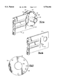
- FIG. 4a is a perspective view of the tension device of the present invention.
- FIG. 4b is a perspective view of the tension bracket of the present invention.
- FIG. 5 is a detailed side view of the tension plate of the present invention.
- a live axle roll up door 10 is typically constructed of a sectional material 11 that is flexible enough for the door to be rolled up in a relatively small diameter roll.
- a live axle 12 turns a drum wheel 14 which is connected to the end of the door 10. As the axle 12 turns in the clockwise direction, the door 10 rolls onto the drum wheel 14, and the door opens. If the axle 12 is turned counterclockwise, the door 10 rolls off of the drum wheels 14 and down toward the ground.
- a tension device 15 which includes a spring 16 that connects to the drum wheel 14 at one end and to a spring connecting plate 22 at the other end.
- the spring connecting plate 22 is supported by a tension bracket 20.
- the spring 16 is preferably a coil spring constructed of metal or other suitable material. As the axle 12 turns counterclockwise and the door 10 is lowered, the spring 16 is twisted and torsional forces are generated. The tension of the spring 16 creates a torsional force that counteracts the weight of the door 10. In order for the door 10 to operate correctly, the tension in the spring 16 must be set correctly. The minimum tension of the spring 16 occurs when the door 10 is completely rolled up and the door 10 is fully open.
- the maximum tension of the spring 16 occurs when the door 10 is touching the ground or fully extended.
- the starting point or minimum tension on the spring 10 is normally adjusted to get the proper performance from the door 10. If the spring 16 has zero tension at the starting point, the amount of tension when the door 10 is fully extended will be the lowest amount possible. If the spring 16 is preset with tension at the starting point, the tension when the door 10 is fully extended will be increased accordingly.
- a standard bracket 18 supports the other end of the axle 12 and allows the axle 12 to rotate freely.
- the tension bracket 20 attaches to support structure 21.
- the end of the axle 12 is held in the axle housing tube 24 by an axle pin 13 which prevents the axle 12 from sliding out.
- the end 11 of the door 10 is connected to the drum wheel 14. When the door 10 is raised, the drum wheel 14 rotates clockwise and the door 10 rolls up onto the drum wheel 14.
- a tension plate 26 is attached to the axle housing tube 24 and contains a series of holes 34 located around its perimeter.
- the tension device 15 includes the axle housing tube 24.
- the axle 12 fits inside the axle housing tube 24 and rotates freely therein.
- the spring 16 connects to the spring connecting plate 22.
- the tension plates 26 sandwich the tension bracket 20 which is fixedly attached to the support structure as shown in FIG. 2.
- the spring connecting plate 22 and the tension plates 26 are all attached to the outside of the axle housing tube 24.
- the plates 22 and 26 are preferably welded to the outside of the axle housing tube 24, but any suitable means for attaching the plates to the outside of the housing 24 may be used.
- the tension bracket 20 fits over the axle housing tube 24, and is sandwiched between the tension plates 26. Accordingly, the axle housing tube 24 and the plates 22 and 26 rotate together and are free to rotate relative to the tension bracket 20.
- the spring 16 (not shown) is bolted to the spring connecting plate 22 through the hole 36. As shown in FIG. 2, the opposite end of the spring 16 is connected to the drum wheel 14. Returning to FIG. 4a, the axle housing tube 24 extends beyond the tension plate 26 for approximately several inches in order to allow room for a tool such as a pipe wrench to be attached to the end.
- the tension pin 32 extends through the tension plates 26 and the tension bracket 20.
- the door 10 In order to test whether the initial tension of the spring 16 is set properly, the door 10 is lowered. By raising and lowering the door 10, the performance characteristics of the door at the current setting are readily observable. If the tension is not set properly, a pipe wrench (not shown) or other suitable tool is applied to the outside of the axle housing tube and the tube is rotated slightly to take the pressure off of the tension pin 32 for removal. With the tension pin 32 removed, the wrench is used to turn the axle and the plates 26 and 22 in either direction depending on whether the spring needs to be tightened or loosened. Once the new setting is found after rotating the plates, the tension pin 32 is reinserted and the pipe wrench or other tool is removed. At this point the door 10 can be operated normally to determine if the new setting is correct.
- FIG. 4b the tension bracket 20 alone is shown with holes 23 positioned to align with the holes in the tension plates 26 (shown in FIG. 4a). These holes are preferably positioned equidistant from the center of the round opening 27 in the tension bracket 20.
- the array of holes 34 around the perimeter of tension plate 26 provides the adjustment capability for the spring 16.
- There are eight holes 34 in the plate 26 which are preferably equally spaced around the perimeter of the plate and therefore, would provide adjustability to one-eighth of a rotation.
- the holes 34 are equidistant from the center of the opening 29 in the tension plate 26.
- the extra hole in the tension bracket allows for a sixteenth of a rotation of adjustability for the spring 16.
- the range of adjustment of the spring 16 may be increased or decreased by adding or subtracting holes.
- the tension device of the present invention offers significant advantages over the prior art devices by providing a simpler device for quickly adjusting the tension of a spring on a live axle door. Also, the device of the present invention greatly reduces the risk of injury as the hands are never required to be near the spring while it is under tension. Further, the device of the present invention provides a greater range of adjustability for the tension of the spring, which in turn provides for optimization of the performance characteristics of the door.
Landscapes
- Engineering & Computer Science (AREA)
- Structural Engineering (AREA)
- Architecture (AREA)
- Civil Engineering (AREA)
- Mechanical Engineering (AREA)
- Closing And Opening Devices For Wings, And Checks For Wings (AREA)
Abstract
Description
Claims (25)
Priority Applications (1)
| Application Number | Priority Date | Filing Date | Title |
|---|---|---|---|
| US08/590,936 US5778490A (en) | 1996-01-24 | 1996-01-24 | Tension device for live axle doors |
Applications Claiming Priority (1)
| Application Number | Priority Date | Filing Date | Title |
|---|---|---|---|
| US08/590,936 US5778490A (en) | 1996-01-24 | 1996-01-24 | Tension device for live axle doors |
Publications (1)
| Publication Number | Publication Date |
|---|---|
| US5778490A true US5778490A (en) | 1998-07-14 |
Family
ID=24364351
Family Applications (1)
| Application Number | Title | Priority Date | Filing Date |
|---|---|---|---|
| US08/590,936 Expired - Lifetime US5778490A (en) | 1996-01-24 | 1996-01-24 | Tension device for live axle doors |
Country Status (1)
| Country | Link |
|---|---|
| US (1) | US5778490A (en) |
Cited By (13)
| Publication number | Priority date | Publication date | Assignee | Title |
|---|---|---|---|---|
| US6125582A (en) * | 1999-05-17 | 2000-10-03 | Overhead Door Corporation | Spring winder support for door counterbalance system |
| US6155327A (en) * | 1999-06-03 | 2000-12-05 | Overhead Door Corporation | Counterbalance system adjustment mechanism for rollup door |
| US6230582B1 (en) * | 1998-09-10 | 2001-05-15 | White Consolidated Industries, Inc. | Crank for adjusting awning roller spring force |
| US6283193B1 (en) * | 1999-07-06 | 2001-09-04 | Harry E. Finch | Adjustable tensioning arrangement for modular security door system |
| WO2002092950A1 (en) * | 2001-05-16 | 2002-11-21 | Wayne-Dalton Corp. | Rolling door tensioner |
| US20030201077A1 (en) * | 2002-04-24 | 2003-10-30 | Mullet Willis Jay | Winding assembly for door counterbalance system |
| US6644378B2 (en) * | 2001-11-02 | 2003-11-11 | Wayne-Dalton Corp. | Tensioning device for a door system |
| US20040020603A1 (en) * | 2000-09-25 | 2004-02-05 | Johansson Gert A. | Information presentation device |
| US20050011620A1 (en) * | 2003-07-15 | 2005-01-20 | Crouch Josh S. | Method and apparatus for suspending a door |
| US20060137138A1 (en) * | 2004-12-27 | 2006-06-29 | Wayne-Dalton Corp. | Winding and anti-drop assembly for door counterbalance system |
| US20090194627A1 (en) * | 2006-08-01 | 2009-08-06 | Gregg Seidel | Rool-up retractable sheet device |
| US20100296683A1 (en) * | 2009-05-22 | 2010-11-25 | Gordon Slippy | Headset with adjustable headband |
| WO2011163459A1 (en) * | 2010-06-23 | 2011-12-29 | Kicher Paul T | System and method for garage door counterbalance |
Citations (18)
| Publication number | Priority date | Publication date | Assignee | Title |
|---|---|---|---|---|
| US1994142A (en) * | 1930-04-24 | 1935-03-12 | Yoder Morris Company | Door operating mechanism |
| US2032951A (en) * | 1931-12-14 | 1936-03-03 | Milton A Pixley | Closure |
| US2059833A (en) * | 1935-02-27 | 1936-11-03 | Wilson J G Corp | Automatic safety overhead door closer |
| US2066558A (en) * | 1932-11-16 | 1937-01-05 | Owen L Dautrick | Door construction |
| US2226017A (en) * | 1939-03-02 | 1940-12-24 | Milton A Pixley | Closure |
| US2630597A (en) * | 1950-02-18 | 1953-03-10 | Stanley Works | Counterbalancing mechanism for articulated overhead doors |
| US2660753A (en) * | 1951-03-08 | 1953-12-01 | Overhead Door Corp | Counterbalance for vertically sliding doors |
| US2786712A (en) * | 1954-11-29 | 1957-03-26 | Theo C Whiting | Counterbalanced door for cargo carrying vehicle bodies |
| US2932057A (en) * | 1959-05-22 | 1960-04-12 | Overhead Door Corp | Counterbalance means for upwardly acting doors and the like |
| US3839827A (en) * | 1973-08-13 | 1974-10-08 | H Dickinson | Overhead door assembly |
| US4356668A (en) * | 1980-10-20 | 1982-11-02 | Wagner Richard P | Method and apparatus for door protection |
| US4472910A (en) * | 1982-09-29 | 1984-09-25 | Chamnberlain Manufacturing Corporation | Integral device for garage door opener |
| US4597224A (en) * | 1984-02-02 | 1986-07-01 | Tucker Derry E | Automatic garage door opener |
| US4817927A (en) * | 1986-08-21 | 1989-04-04 | Martin Door Manufacturing | Coil torsion spring mounting cones with groove break and method of mounting |
| US4930182A (en) * | 1989-04-14 | 1990-06-05 | Apco Power-Unit Corporation | Apparatus for counterbalancing an overhead door |
| US4981165A (en) * | 1989-04-11 | 1991-01-01 | Millco Products, Inc. | Spring adjustment device for overhead doors |
| US5222327A (en) * | 1991-07-22 | 1993-06-29 | Fellows Donna M | Side mount garage door operator |
| US5239777A (en) * | 1992-03-24 | 1993-08-31 | Atlas Roll-Lite Door Corporation | Overhead door pre-loaded and pre-assembled torsion spring counterbalance assembly |
-
1996
- 1996-01-24 US US08/590,936 patent/US5778490A/en not_active Expired - Lifetime
Patent Citations (18)
| Publication number | Priority date | Publication date | Assignee | Title |
|---|---|---|---|---|
| US1994142A (en) * | 1930-04-24 | 1935-03-12 | Yoder Morris Company | Door operating mechanism |
| US2032951A (en) * | 1931-12-14 | 1936-03-03 | Milton A Pixley | Closure |
| US2066558A (en) * | 1932-11-16 | 1937-01-05 | Owen L Dautrick | Door construction |
| US2059833A (en) * | 1935-02-27 | 1936-11-03 | Wilson J G Corp | Automatic safety overhead door closer |
| US2226017A (en) * | 1939-03-02 | 1940-12-24 | Milton A Pixley | Closure |
| US2630597A (en) * | 1950-02-18 | 1953-03-10 | Stanley Works | Counterbalancing mechanism for articulated overhead doors |
| US2660753A (en) * | 1951-03-08 | 1953-12-01 | Overhead Door Corp | Counterbalance for vertically sliding doors |
| US2786712A (en) * | 1954-11-29 | 1957-03-26 | Theo C Whiting | Counterbalanced door for cargo carrying vehicle bodies |
| US2932057A (en) * | 1959-05-22 | 1960-04-12 | Overhead Door Corp | Counterbalance means for upwardly acting doors and the like |
| US3839827A (en) * | 1973-08-13 | 1974-10-08 | H Dickinson | Overhead door assembly |
| US4356668A (en) * | 1980-10-20 | 1982-11-02 | Wagner Richard P | Method and apparatus for door protection |
| US4472910A (en) * | 1982-09-29 | 1984-09-25 | Chamnberlain Manufacturing Corporation | Integral device for garage door opener |
| US4597224A (en) * | 1984-02-02 | 1986-07-01 | Tucker Derry E | Automatic garage door opener |
| US4817927A (en) * | 1986-08-21 | 1989-04-04 | Martin Door Manufacturing | Coil torsion spring mounting cones with groove break and method of mounting |
| US4981165A (en) * | 1989-04-11 | 1991-01-01 | Millco Products, Inc. | Spring adjustment device for overhead doors |
| US4930182A (en) * | 1989-04-14 | 1990-06-05 | Apco Power-Unit Corporation | Apparatus for counterbalancing an overhead door |
| US5222327A (en) * | 1991-07-22 | 1993-06-29 | Fellows Donna M | Side mount garage door operator |
| US5239777A (en) * | 1992-03-24 | 1993-08-31 | Atlas Roll-Lite Door Corporation | Overhead door pre-loaded and pre-assembled torsion spring counterbalance assembly |
Cited By (25)
| Publication number | Priority date | Publication date | Assignee | Title |
|---|---|---|---|---|
| US6230582B1 (en) * | 1998-09-10 | 2001-05-15 | White Consolidated Industries, Inc. | Crank for adjusting awning roller spring force |
| US6125582A (en) * | 1999-05-17 | 2000-10-03 | Overhead Door Corporation | Spring winder support for door counterbalance system |
| US6155327A (en) * | 1999-06-03 | 2000-12-05 | Overhead Door Corporation | Counterbalance system adjustment mechanism for rollup door |
| WO2000074540A1 (en) * | 1999-06-03 | 2000-12-14 | Overhead Door Corporation | Counterbalance system adjustment mechanism for rollup door |
| US6283193B1 (en) * | 1999-07-06 | 2001-09-04 | Harry E. Finch | Adjustable tensioning arrangement for modular security door system |
| US20040020603A1 (en) * | 2000-09-25 | 2004-02-05 | Johansson Gert A. | Information presentation device |
| US20060151124A1 (en) * | 2000-09-25 | 2006-07-13 | Johansson Gert A | Information presentation device |
| US7185690B2 (en) * | 2000-09-25 | 2007-03-06 | Marcbric Intressenter Ab | Information presentation device |
| US7040372B2 (en) * | 2000-09-25 | 2006-05-09 | Mark Bric Intressenter Ab | Information presentation device |
| US6527037B2 (en) | 2001-05-16 | 2003-03-04 | Wayne-Dalton Corp. | Rolling door tensioner |
| WO2002092950A1 (en) * | 2001-05-16 | 2002-11-21 | Wayne-Dalton Corp. | Rolling door tensioner |
| US6644378B2 (en) * | 2001-11-02 | 2003-11-11 | Wayne-Dalton Corp. | Tensioning device for a door system |
| US20030201077A1 (en) * | 2002-04-24 | 2003-10-30 | Mullet Willis Jay | Winding assembly for door counterbalance system |
| US7686061B2 (en) | 2002-04-24 | 2010-03-30 | Overhead Door Corporation | Winding assembly for door counterbalance system |
| US6896027B2 (en) * | 2003-07-15 | 2005-05-24 | Nci Building Systems, L.P. | Method and apparatus for suspending a door |
| WO2005010305A1 (en) * | 2003-07-15 | 2005-02-03 | Nci Building Systems, L.P. | Apparatus for suspending a door |
| US20050011620A1 (en) * | 2003-07-15 | 2005-01-20 | Crouch Josh S. | Method and apparatus for suspending a door |
| US20060137138A1 (en) * | 2004-12-27 | 2006-06-29 | Wayne-Dalton Corp. | Winding and anti-drop assembly for door counterbalance system |
| US7254868B2 (en) | 2004-12-27 | 2007-08-14 | Wayne-Dalton Corp. | winding and anti-drop assembly for door counterbalance system |
| US20090194627A1 (en) * | 2006-08-01 | 2009-08-06 | Gregg Seidel | Rool-up retractable sheet device |
| US8281845B2 (en) * | 2006-08-01 | 2012-10-09 | Gregg Seidel | Roll-up retractable sheet device |
| US20100296683A1 (en) * | 2009-05-22 | 2010-11-25 | Gordon Slippy | Headset with adjustable headband |
| US8160287B2 (en) * | 2009-05-22 | 2012-04-17 | Vocollect, Inc. | Headset with adjustable headband |
| WO2011163459A1 (en) * | 2010-06-23 | 2011-12-29 | Kicher Paul T | System and method for garage door counterbalance |
| US9156151B2 (en) | 2010-06-23 | 2015-10-13 | Paul T. Kicher | System and method for garage door counterbalance |
Similar Documents
| Publication | Publication Date | Title |
|---|---|---|
| US5778490A (en) | Tension device for live axle doors | |
| US4882806A (en) | Counterbalancing torsion spring mechanism for devices which move up and down and method of setting the torsion springs thereof | |
| AU622268B2 (en) | Roller blind mounting and rolling systems | |
| JP3510257B2 (en) | Compact balancing system for prefabricated doors | |
| US6408925B1 (en) | Counterbalancing apparatus for roll-up door | |
| US4757852A (en) | Automatic mosquito curtain for windows and doors | |
| US2626421A (en) | Hinge structure | |
| US20020157797A1 (en) | Extension spring counterbalance system | |
| US2630597A (en) | Counterbalancing mechanism for articulated overhead doors | |
| US4757853A (en) | Safety device for garage door springs | |
| US7296607B2 (en) | Side mount counterbalance system for upward acting door | |
| US5513469A (en) | Retractable sliding door | |
| US5768828A (en) | Counterbalancing mechanism | |
| US4931708A (en) | Independent band spring door gear motor operator | |
| US3826044A (en) | Roller assembly | |
| US4012008A (en) | Window sash balancer | |
| US5544689A (en) | Window attachment screen system | |
| US6896027B2 (en) | Method and apparatus for suspending a door | |
| US2294360A (en) | Counterbalance for vertically sliding doors | |
| US4588175A (en) | Torsion spring apparatus and method | |
| CA2348101A1 (en) | Hand tool bending machine for springs used in anchor plugs | |
| US5638640A (en) | Safety device for spring-loaded overhead doors | |
| CA2057615C (en) | Spring-biased gate assembly | |
| JPS6133117B2 (en) | ||
| US5558147A (en) | Door counterweight assembly |
Legal Events
| Date | Code | Title | Description |
|---|---|---|---|
| STCF | Information on status: patent grant |
Free format text: PATENTED CASE |
|
| FPAY | Fee payment |
Year of fee payment: 4 |
|
| FEPP | Fee payment procedure |
Free format text: PAT HOLDER CLAIMS SMALL ENTITY STATUS, ENTITY STATUS SET TO SMALL (ORIGINAL EVENT CODE: LTOS); ENTITY STATUS OF PATENT OWNER: LARGE ENTITY Free format text: PAT HOLDER NO LONGER CLAIMS SMALL ENTITY STATUS, ENTITY STATUS SET TO UNDISCOUNTED (ORIGINAL EVENT CODE: STOL); ENTITY STATUS OF PATENT OWNER: LARGE ENTITY |
|
| REFU | Refund |
Free format text: REFUND - PAYMENT OF MAINTENANCE FEE, 8TH YR, SMALL ENTITY (ORIGINAL EVENT CODE: R2552); ENTITY STATUS OF PATENT OWNER: LARGE ENTITY |
|
| FPAY | Fee payment |
Year of fee payment: 8 |
|
| AS | Assignment |
Owner name: NCI GROUP, INC., TEXAS Free format text: ASSIGNMENT OF ASSIGNORS INTEREST;ASSIGNOR:NCI BUILDING SYSTEMS, L.P.;REEL/FRAME:020098/0567 Effective date: 20071029 |
|
| FEPP | Fee payment procedure |
Free format text: PAT HOLDER NO LONGER CLAIMS SMALL ENTITY STATUS, ENTITY STATUS SET TO UNDISCOUNTED (ORIGINAL EVENT CODE: STOL); ENTITY STATUS OF PATENT OWNER: LARGE ENTITY |
|
| FPAY | Fee payment |
Year of fee payment: 12 |