US20200059889A1 - Terminal apparatus, location server, and method in terminal apparatus - Google Patents
Terminal apparatus, location server, and method in terminal apparatus Download PDFInfo
- Publication number
- US20200059889A1 US20200059889A1 US16/610,235 US201816610235A US2020059889A1 US 20200059889 A1 US20200059889 A1 US 20200059889A1 US 201816610235 A US201816610235 A US 201816610235A US 2020059889 A1 US2020059889 A1 US 2020059889A1
- Authority
- US
- United States
- Prior art keywords
- terminal apparatus
- information
- transmission beam
- transmission
- reception
- Prior art date
- Legal status (The legal status is an assumption and is not a legal conclusion. Google has not performed a legal analysis and makes no representation as to the accuracy of the status listed.)
- Abandoned
Links
Images


Classifications
-
- G—PHYSICS
- G01—MEASURING; TESTING
- G01S—RADIO DIRECTION-FINDING; RADIO NAVIGATION; DETERMINING DISTANCE OR VELOCITY BY USE OF RADIO WAVES; LOCATING OR PRESENCE-DETECTING BY USE OF THE REFLECTION OR RERADIATION OF RADIO WAVES; ANALOGOUS ARRANGEMENTS USING OTHER WAVES
- G01S1/00—Beacons or beacon systems transmitting signals having a characteristic or characteristics capable of being detected by non-directional receivers and defining directions, positions, or position lines fixed relatively to the beacon transmitters; Receivers co-operating therewith
- G01S1/02—Beacons or beacon systems transmitting signals having a characteristic or characteristics capable of being detected by non-directional receivers and defining directions, positions, or position lines fixed relatively to the beacon transmitters; Receivers co-operating therewith using radio waves
- G01S1/08—Systems for determining direction or position line
- G01S1/44—Rotating or oscillating beam beacons defining directions in the plane of rotation or oscillation
-
- H—ELECTRICITY
- H04—ELECTRIC COMMUNICATION TECHNIQUE
- H04B—TRANSMISSION
- H04B7/00—Radio transmission systems, i.e. using radiation field
- H04B7/02—Diversity systems; Multi-antenna system, i.e. transmission or reception using multiple antennas
- H04B7/04—Diversity systems; Multi-antenna system, i.e. transmission or reception using multiple antennas using two or more spaced independent antennas
- H04B7/06—Diversity systems; Multi-antenna system, i.e. transmission or reception using multiple antennas using two or more spaced independent antennas at the transmitting station
- H04B7/0613—Diversity systems; Multi-antenna system, i.e. transmission or reception using multiple antennas using two or more spaced independent antennas at the transmitting station using simultaneous transmission
- H04B7/0615—Diversity systems; Multi-antenna system, i.e. transmission or reception using multiple antennas using two or more spaced independent antennas at the transmitting station using simultaneous transmission of weighted versions of same signal
- H04B7/0617—Diversity systems; Multi-antenna system, i.e. transmission or reception using multiple antennas using two or more spaced independent antennas at the transmitting station using simultaneous transmission of weighted versions of same signal for beam forming
-
- H—ELECTRICITY
- H04—ELECTRIC COMMUNICATION TECHNIQUE
- H04B—TRANSMISSION
- H04B7/00—Radio transmission systems, i.e. using radiation field
- H04B7/02—Diversity systems; Multi-antenna system, i.e. transmission or reception using multiple antennas
- H04B7/04—Diversity systems; Multi-antenna system, i.e. transmission or reception using multiple antennas using two or more spaced independent antennas
- H04B7/08—Diversity systems; Multi-antenna system, i.e. transmission or reception using multiple antennas using two or more spaced independent antennas at the receiving station
- H04B7/0837—Diversity systems; Multi-antenna system, i.e. transmission or reception using multiple antennas using two or more spaced independent antennas at the receiving station using pre-detection combining
- H04B7/0842—Weighted combining
- H04B7/086—Weighted combining using weights depending on external parameters, e.g. direction of arrival [DOA], predetermined weights or beamforming
-
- H—ELECTRICITY
- H04—ELECTRIC COMMUNICATION TECHNIQUE
- H04B—TRANSMISSION
- H04B7/00—Radio transmission systems, i.e. using radiation field
- H04B7/02—Diversity systems; Multi-antenna system, i.e. transmission or reception using multiple antennas
- H04B7/04—Diversity systems; Multi-antenna system, i.e. transmission or reception using multiple antennas using two or more spaced independent antennas
- H04B7/08—Diversity systems; Multi-antenna system, i.e. transmission or reception using multiple antennas using two or more spaced independent antennas at the receiving station
- H04B7/0868—Hybrid systems, i.e. switching and combining
- H04B7/088—Hybrid systems, i.e. switching and combining using beam selection
-
- H—ELECTRICITY
- H04—ELECTRIC COMMUNICATION TECHNIQUE
- H04W—WIRELESS COMMUNICATION NETWORKS
- H04W64/00—Locating users or terminals or network equipment for network management purposes, e.g. mobility management
- H04W64/006—Locating users or terminals or network equipment for network management purposes, e.g. mobility management with additional information processing, e.g. for direction or speed determination
Definitions
- the present invention relates to a terminal apparatus, a location server, and a method in the terminal apparatus.
- the communication area can be widened by forming a cellular configuration in which multiple areas, covered by base station apparatuses (base stations, transmission stations, transmission points, downlink transmission devices, uplink reception devices, a group of transmit antennas, a group of transmit antenna ports, component carriers, eNodeB, Access Point, AP, transmission devices) or transmission stations equivalent to the base station apparatuses, are deployed in the form of multiple cells (Cells).
- base station apparatuses base stations, transmission stations, transmission points, downlink transmission devices, uplink reception devices, a group of transmit antennas, a group of transmit antenna ports, component carriers, eNodeB, Access Point, AP, transmission devices
- Cells multiple cells
- a terminal apparatus (reception station, reception point, downlink reception apparatus, uplink transmission apparatus, receive antenna group, receive antenna port group, UE, station, and STA) is connected to the base station apparatus.
- frequency efficiency can be improved by using the same frequency among neighboring cells or sectors.
- a specification for communication using high frequency bands such as millimeter waves is planned to be formulated for further data rate improvement. Beamforming is assumed in the communication in the high frequency band.
- PTL 1 discloses an operation method for beamforming by beam sweeping.
- NPL 1 discloses a method for position estimation using a signal in a 60 GHz band.
- AR Augmented Reality
- VR Virtual Reality
- robots have expanded rapidly.
- NPL 1 the position estimation method disclosed in NPL 1 has a problem that the orientation of the terminal cannot be estimated.
- An aspect of the present invention has been made in view of such circumstances, and an object of the present invention is to provide a terminal apparatus, a location server, and a method in the terminal apparatus, capable of estimating an orientation of the terminal with high accuracy.
- a terminal apparatus, a location server, and a method in the terminal apparatus according to an aspect of the present invention are configured as follows.
- a terminal apparatus includes: a first direction configuring unit configured to receive transmission beam information that is information of a transmission beam used by a transmission device and configure a first direction that is a direction vector of the transmission beam in a first coordinate system based on the transmission beam information; a radio receiving unit configured to configure a reception beam used for reception of a signal from the transmission device; a second direction configuring unit configured to configure a second direction that is a direction vector of the reception beam in a second coordinate system; and an orientation measuring unit configured to perform measurement of an orientation of the terminal apparatus itself based on the first direction and the second direction.
- the transmission beam information may be an azimuth angle and an elevation angle of the transmission beam used by the transmission device, in the first coordinate system, and the first direction configuring unit may configure the first direction based on the azimuth angle and the elevation angle.
- the transmission beam information may be the direction vector of the transmission beam used by the transmission device, in the first coordinate system, and the first direction configuring unit may configure the first direction based on the direction vector.
- the second coordinate system may be a coordinate system fixed to the orientation.
- the orientation measuring unit may receive beam orientation measurement information for indicating whether or not the transmission beam is used for orientation measurement, and the orientation measuring unit may perform the measurement based on the first direction and the second direction, corresponding to the transmission beam indicated by the beam orientation measurement information.
- a location server is a location server in a system in which multiple base station apparatuses and a terminal apparatus communicate using beamforming
- the location server includes: a receiver configured to receive transmission beam information that is information of a transmission beam used by the base station apparatus and reception beam information that is information of a reception beam used by the terminal apparatus; a first direction configuring unit configured to configure a first direction that is a direction vector of the transmission beam in a first coordinate system based on the transmission beam information; a second direction managing unit configured to configure a second direction that is a direction vector of the reception beam in a second coordinate system of the terminal apparatus based on the reception beam information; and a direction managing unit configured to perform measurement of an orientation of the terminal apparatus based on the first direction and the second direction.
- the transmission beam information and the reception beam information may be an azimuth angle and an elevation angle of the transmission beam and an azimuth angle and an elevation angle of the reception beam
- the first direction configuring unit may configure the first direction based on the azimuth angle and the elevation angle of the transmission beam
- the second direction configuring unit may configure the second direction based on the azimuth angle and the elevation angle of the reception beam.
- the transmission beam information and the reception beam information may be a vector of the transmission beam and a vector of the reception beam
- the first direction configuring unit may configure the first direction based on the vector of the transmission beam
- the second direction configuring unit may configure the second direction based on the vector of the reception beam
- the direction managing unit may estimate whether or not there is reflection between the transmission beam and the reception beam, and may measure the orientation based on the first direction and the second direction of the transmission beam and the reception beam between which there is none of the reflection.
- a method is a method in a terminal apparatus for communicating with multiple transmission devices using beamforming, the method includes the steps of: receiving transmission beam information that is information of a transmission beam used by the transmission device and configuring a first direction that is a direction vector of the transmission beam in a first coordinate system based on the transmission beam information; configuring a reception beam used for reception of a signal from the transmission device; configuring a second direction that is a direction vector of the reception beam in a second coordinate system; and performing measurement of an orientation of the terminal apparatus itself based on the first direction and the second direction.
- a terminal apparatus can estimate an orientation of the terminal apparatus itself with high accuracy.
- FIG. 1 is a schematic block diagram illustrating a configuration example of a communication system according to a first embodiment.
- FIG. 2 is a schematic block diagram illustrating an example of communication among apparatuses of the communication system according to the first embodiment.
- FIG. 3 is a diagram illustrating an example of a case in which a base station apparatus and a terminal apparatus determine a beam using beam sweeping.
- FIG. 4 is a diagram illustrating an example of a relationship between a base station apparatus and a terminal antenna of a terminal apparatus.
- FIG. 5 is a schematic block diagram illustrating a configuration example of a base station apparatus according to the first embodiment.
- FIG. 6 is a schematic block diagram illustrating a configuration example of a terminal apparatus according to the first embodiment.
- FIG. 7 is a schematic block diagram illustrating a configuration example of a location server.
- FIG. 8 is a schematic block diagram illustrating a configuration example of a terminal apparatus according to a second embodiment.
- FIG. 9 is a schematic block diagram illustrating a configuration example of a location server according to the second embodiment.
- a communication system includes a base station apparatus (a transmission device, a cell, a transmission point, a group of transmit antennas, a group of transmit antenna ports, a component carrier, eNodeB, and an access point), a terminal apparatus (a terminal, a mobile terminal, a reception point, a reception terminal, a reception device, a group of receive antennas, a group of receive antenna ports, UE, a station), and a location server.
- the location server includes, for example, an Enhanced Serving Mobile Location Centre (E-SMLC), a Secure User Plane Location (SUPL), and an SUPL Location Platform (SLP).
- E-SMLC Enhanced Serving Mobile Location Centre
- SUPL Secure User Plane Location
- SLP SUPL Location Platform
- a base station apparatus connected to a terminal apparatus is referred to as a serving cell.
- the base station apparatus and the terminal apparatus in the present embodiment can communicate in a licensed band and/or an unlicensed band.
- FIG. 1 is a diagram illustrating an example of a communication system according to the present embodiment.
- the communication system according to the present embodiment includes base station apparatuses 10 - 1 , 10 - 2 , 10 - 3 , and 10 - 4 , a terminal apparatus 20 , a core network 30 , and a location server 40 .
- the base station apparatuses 10 - 1 , 10 - 2 , 10 - 3 , and 10 - 4 perform radio communication with the terminal apparatus 20 .
- the base station apparatuses 10 - 1 , 10 - 2 , 10 - 3 , and 10 - 4 are connected to the location server 40 via the core network 30 .
- the location server 40 can support location estimation and orientation estimation of the terminal apparatus 20 .
- the orientation refers to an orientation (direction) of the terminal apparatus 20 in a global coordinate system, for example.
- the orientation is not limited to that in the global coordinate system, and may be the orientation of the terminal apparatus 20 in a coordinate system shared by a base station apparatus 10 and/or the location server 40 and the terminal apparatus 20 .
- the terminal apparatus 20 and the location server 40 perform communication by a positioning protocol (e.g. LPP), this communication is relayed by the base station apparatuses 10 - 1 , 10 - 2 , 10 - 3 , and 10 - 4 and the core network 30 .
- a positioning protocol e.g. LPP
- the location server 40 and the base station apparatuses 10 - 1 , 10 - 2 , 10 - 3 , and 10 - 4 perform communication by a positioning protocol A (e.g., LPPa), this communication is relayed by the core network 30 .
- the base station apparatuses 10 - 1 , 10 - 2 , 10 - 3 , and 10 - 4 and the terminal apparatus 20 communicate using beamforming. Note that although the description is given using the four base station apparatuses, more or fewer apparatuses than this may be used.
- FIG. 2 is a schematic block diagram illustrating communication among apparatuses of the communication system according to the present embodiment.
- the communication system includes the four base station apparatuses 10 - 1 , 10 - 2 , 10 - 3 , and 10 - 4 , but the base station apparatus 10 in FIG. 2 is representative of these four base station apparatuses 10 - 1 , 10 - 2 , 10 - 3 , and 10 - 4 .
- the base station apparatus 10 performs communication with the terminal apparatus 20 using the beamforming.
- the base station apparatus 10 performs communication with the location server 40 by the LPPa.
- the location server 40 can obtain, via the LPPa, a direction of a beam used by the base station apparatus 10 .
- the direction of the beam can be a direction vector or a set of an azimuth angle and an elevation angle in the global coordinate system.
- the global coordinate system can be, for example, a right-handed coordinate system in which an x axis is taken as the east direction, a y axis is taken as the north direction, and a z axis is taken as the zenith direction.
- the terminal apparatus 20 performs communication with the location server 40 by the LPP.
- the terminal apparatus 20 can receive, via the LPP, the direction of the transmission beam used by the base station apparatus 10 from the location server 40 .
- the terminal apparatus 20 may receive the location of the base station apparatus 10 from the location server 40 . In this case, the terminal apparatus 20 can estimate the direction from the base station apparatus 10 to the terminal apparatus 20 by measuring the location of the terminal apparatus.
- FIG. 3 is a diagram illustrating an example of a case in which the base station apparatus 10 and the terminal apparatus 20 determine a beam using beam sweeping.
- a reference signal a positioning reference signal, a channel state information reference signal, a cell-specific reference signal, or the like
- a synchronization signal can be used for the beam sweeping.
- a base station antenna 100 includes base station beam candidates 101 - 1 , 101 - 2 , 101 - 3 , and 101 - 4 .
- a terminal antenna 200 includes terminal beam candidates 201 - 1 , 201 - 2 , 201 - 3 , and 201 - 4 .
- the base station apparatus 10 can transmit a signal, by using the base station beam candidate 101 - 1 as a transmission beam, to the terminal apparatus 20 .
- the terminal apparatus 20 can receive the signal from the base station apparatus 10 , by using the terminal beam candidates 201 - 1 , 201 - 2 , 201 - 3 , and 201 - 4 as a reception beam.
- the terminal apparatus 20 can make the beam candidate, among the terminal beam candidates 201 - 1 , 201 - 2 , 201 - 3 , and 201 - 4 , in which a Signal to Noise Ratio (SNR), a beam gain, Reference Signal Received Power (RSRP), Reference Signal Received Quality (RSRQ), or the like is maximized, a reception beam.
- SNR Signal to Noise Ratio
- RSRP Reference Signal Received Power
- RSRQ Reference Signal Received Quality
- the base station beam candidate 101 - m the transmission beam of the base station apparatus 10
- the terminal beam candidate 201 - n the reception beam of the terminal apparatus 20 .
- the number of base station beam candidates and the number of terminal beam candidates are described as four, but the number may be greater or less than this.
- the case that the base station apparatus 10 performs transmission and the terminal apparatus 20 performs reception has been described, but the terminal apparatus 20 may perform transmission and the base station apparatus 10 may perform reception.
- the m base station beam candidates described above may be all possible beam candidates by the base station apparatus 10 , or may be some beam candidates thereof.
- the n terminal beam candidates described above may be all possible beam candidates by the terminal apparatus 20 , or may be some beam candidates thereof.
- the beam candidate described above may also be a horizontal beam or a vertical beam.
- each of the base station apparatus 10 /the terminal apparatus 20 searches for the suitable horizontal beam and vertical beam.
- a vertical direction of the antenna is also referred to as a first dimension and a horizontal direction of the antenna is also referred to as a second dimension.
- the base station apparatus 10 reports the base station beam direction of the determined base station beam candidate in the global coordinate system to the location server 40 via the LPPa.
- the location server 40 notifies the terminal apparatus 20 of the base station beam direction via the LPP.
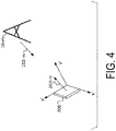
- FIG. 4 is a diagram illustrating a relationship between a base station apparatus 10 - m and the terminal antenna 200 of the terminal apparatus 20 .
- the terminal antenna 200 is a planar antenna on a plane formed by an x′ axis and a z′ axis of a local coordinate system of the terminal 20 .
- a base station beam direction 102 - m and a terminal beam direction 202 - m can be determined by the above-described beam sweeping and the like.
- An example of estimating the orientation of the terminal apparatus 20 will be described below, by estimating a rotation matrix from the global coordinate system to the local coordinate system of the terminal apparatus 20 .
- a direction vector obtained by multiplying the vector representing the base station beam direction 102 - m in the global coordinate system by ⁇ 1 is taken as c m
- a vector representing the terminal beam direction 202 - m in the local coordinate system of the terminal apparatus 20 is taken as e m .
- the number of base station apparatuses is taken as M.
- diag( ) represents a diagonal matrix in which the arguments are diagonally arranged
- det( ) represents a determinant of a matrix indicated by the argument.
- the quaternion can be expressed by the sum of a scalar and a three-dimensional vector.
- the right-hand screw rotation of an angle ⁇ with a certain direction vector n as an axis can be represented by a quaternion that is cos(0.5 ⁇ )+nsin(0.5 ⁇ ).
- the matrix M described above is used.
- a p-row q-column component of the matrix M is taken as m pq .
- a 4 ⁇ 4 dimensional matrix N such as Equation (1) below, is calculated.
- Equation ⁇ ⁇ 1 N ( m 11 + m 22 + m 33 m 23 - m 32 m 31 - m 13 m 12 - m 21 m 23 - m 32 m 11 - m 22 - m 33 m 12 + m 21 m 31 + m 13 m 31 - m 13 m 12 + m 21 - m 11 + m 23 + m 32 m 22 - m 33 m 12 - m 21 m 31 + m 13 m 23 + m 32 - m 11 - m 22 + m 33 ) ( 1 )
- N is subjected to eigenvalue decomposition, and a normalized eigenvector of size four corresponding to the maximum eigenvalue thereof is taken as b.
- the quaternion is expressed by the sum of the scalar and the three-dimensional vector, the quaternion in which a first component of a vector b is taken as the scalar portion and a three-dimensional vector including second, third, and fourth components of the vector b is taken as a vector portion is a quaternion to be obtained.
- FIG. 5 is a schematic block diagram illustrating a configuration example of the base station apparatus 10 according to the present embodiment.
- the base station apparatus 10 is configured to include a higher layer processing unit (higher layer processing step) 1001 , a controller (controlling step) 1002 , a transmitter (transmitting step) 1003 , a receiver (receiving step) 1004 , a physical signal generating unit (physical signal generating step) 10031 , a transmission beam configuring unit (transmission beam configuring step) 10032 , a radio receiving unit (radio receiving step) 10041 , and a beam information receiving unit (beam information receiving step) 10042 .
- the transmitter 1003 may include a transmit antenna.
- the receiver 1005 may include a receive antenna. Additionally, the transmit antenna and the receive antenna may be the same antenna.
- the higher layer processing unit 1001 performs processing of a Medium Access Control (MAC) layer, a Packet Data Convergence Protocol (PDCP) layer, a Radio Link Control (RLC) layer, and a Radio Resource Control (RRC) layer. Furthermore, the higher layer processing unit 1001 generates information necessary for control of the transmitter 1003 and the receiver 1004 , and outputs the generated information to the controller 1002 .
- MAC Medium Access Control
- PDCP Packet Data Convergence Protocol
- RLC Radio Link Control
- RRC Radio Resource Control
- the higher layer processing unit 1001 receives information of a terminal apparatus, such as a capability of the terminal apparatus (UE capability), from the terminal apparatus.
- a terminal apparatus such as a capability of the terminal apparatus (UE capability)
- the terminal apparatus transmits the function of the terminal itself to the base station apparatus by higher layer signaling.
- information of a terminal apparatus includes information for indicating whether the terminal apparatus supports a prescribed function, or information for indicating that the terminal apparatus has completed the introduction and test of a prescribed function.
- information of whether the prescribed function is supported includes information of whether the introduction and test of the prescribed function have been completed.
- the terminal apparatus transmits information (parameters) for indicating whether the prescribed function is supported.
- the terminal apparatus does not transmit information (parameters) for indicating whether the prescribed function is supported.
- whether the prescribed function is supported is reported by whether information (parameters) indicating whether the prescribed function is supported is transmitted.
- the information (parameters) indicating whether the prescribed function is supported may be reported using one bit of 1 or 0.
- the higher layer processing unit 1001 generates, or acquires from a higher node, downlink data (transport block), system information, an RRC message, a MAC Control Element (CE), and the like.
- the higher layer processing unit 1001 outputs the downlink data to the transmitter 1003 , and outputs other information to the controller 1002 .
- the higher layer processing unit 1001 manages various types of configuration information about the terminal apparatus.
- the higher layer processing unit 1001 determines a frequency and a subframe to which a physical channel is allocated, a coding rate and modulation scheme (or MCS) for the physical channel, transmit power, and the like.
- the higher layer processing unit 1001 outputs the determined information to the controller 1002 .
- the higher layer processing unit 1001 generates information to be used for scheduling the physical channel, based on the result of the scheduling.
- the higher layer processing unit 1001 outputs the generated information to the controller 1002 .
- the controller 1002 Based on the information input from the higher layer processing unit 1001 , the controller 1002 generates a control signal for controlling the transmitter 1003 and the receiver 1004 .
- the controller 1002 generates downlink control information based on the information input from the higher layer processing unit 1001 , and outputs the generated information to the transmitter 1003 .
- the transmitter 1003 generates a downlink reference signal in accordance with the control signal input from the controller 1002 , codes and modulates an HARQ indicator, the downlink control information, and the downlink data that are input from the higher layer processing unit 1001 , multiplexes the downlink physical channel and the downlink reference signal, and transmits a signal obtained through the multiplexing to the terminal apparatus 20 through the transmit and/or receive antenna.
- the physical signal generating unit 10031 generates an Orthogonal Frequency Division Multiplexing (OFDM) signal from the HARQ indicator, the downlink control information, the downlink reference signal, and the downlink data input from the higher layer processing unit 1001 .
- OFDM Orthogonal Frequency Division Multiplexing
- a cyclic prefix (CP) is added to the OFDM symbol, and a baseband digital signal is generated.
- the baseband digital signal is converted into an analog signal, excess frequency components are removed therefrom by filtering, up-conversion to a carrier frequency is performed, power amplification is performed, and the resultant signal is output through the transmit antenna.
- the generated signal is not limited to the OFDM signal, and may be a single carrier signal, a Code Division Multiple Access (CDMA) signal, or the like.
- CDMA Code Division Multiple Access
- the transmission beam configuring unit 10032 configures the transmission beam used by the base station apparatus 10 .
- the transmission beam configuring unit 10032 can configure the transmission beam by using the beam sweeping. Specifically, it is possible to configure the transmission beam candidate, which is received by the beam information receiving unit 10042 described later, with the maximum SNR in the terminal apparatus 20 , to the transmission beam.
- the transmission beam configuring unit 10032 can report a direction of the configured transmission beam in the global coordinate system to the location server 40 via the higher layer processing unit 1001 . Information relating to the direction of the transmission beam can be referred to as transmission beam information.
- the radio receiving unit 10041 demultiplexes, demodulates, and decodes a reception signal received from the terminal apparatus, and outputs information resulting from the decoding to the higher layer processing unit 1001 or the beam information receiving unit 10042 .
- the radio receiving unit 10041 converts, by down-conversion, an uplink signal received through the receive antenna into a baseband signal, removes unnecessary frequency components from the baseband signal, controls the amplification level in such a manner as to suitably maintain a signal level, performs orthogonal demodulation based on an in-phase component and an orthogonal component of the received signal, and converts the resulting orthogonally-demodulated analog signal into a digital signal.
- the radio receiving unit 10041 removes a portion corresponding to the CP from the digital signal resulting from the conversion.
- the radio receiving unit 10041 performs Fast Fourier Transform (FFT) on the signal from which the CP has been removed, and extracts a signal in the frequency domain.
- FFT Fast Fourier Transform
- the extracted signal in the frequency domain is demultiplexed into an uplink physical channel, a signal such as an uplink reference signal, and the like.
- the radio receiving unit 10041 performs Inverse Discrete Fourier Transform (IDFT) of PUSCH/NPUSCH, acquires a modulation symbol, and demodulates the reception signal.
- IDFT Inverse Discrete Fourier Transform
- IFFT corresponding to the number of points of the above-described inverse discrete Fourier transform may be used.
- the radio receiving unit 10041 decodes the coded bits that have been demodulated, at a coding rate, in compliance with a predetermined coding scheme, that is predetermined or notified from the base station apparatus to the terminal apparatus 20 in advance by using the uplink grant, and outputs the decoded uplink data and uplink control information to the higher layer processing unit 1001 .
- the decoding is performed by using the coded bits input from the higher layer processing unit 1001 and retained in an HARQ buffer, and the demodulated coded bits.
- the beam information receiving unit 10042 receives beam information from the terminal apparatus 20 necessary for the transmission beam configuring unit 10032 to configure the transmission beam.
- the beam information is, for example, identification information of the transmission beam in which the SNR measured by the terminal apparatus 20 is maximized at the time of the beam sweeping.
- the identification information may be, for example, a transmission beam number (transmission beam index) or a resource number (resource index).
- FIG. 6 is a schematic block diagram illustrating a configuration of the terminal apparatus 20 according to the present embodiment.
- the terminal apparatus 20 is configured to include a higher layer processing unit (higher layer processing step) 2001 , a controller (controlling step) 2002 , a transmitter (transmitting step) 2003 , and a receiver (receiving step) 2004 .
- the transmitter 2003 is configured to include a physical signal generating unit (physical signal generating step) 20031 , a beam information generating unit (beam information generating step) 20032 , and a local direction configuring unit (second direction configuring unit, local direction configuring step, second direction configuring step) 20033 .
- the receiver 2004 is configured to include a radio receiving unit (radio receiving step) 20041 , a global direction configuring unit (first direction configuring unit, global direction configuring step, first direction configuring step) 20042 , and an orientation measuring unit (orientation measuring step) 20044 .
- a radio receiving unit radio receiving step
- a global direction configuring unit first direction configuring unit, global direction configuring step, first direction configuring step
- an orientation measuring unit orientation measuring step
- the higher layer processing unit 2001 outputs, to the transmitter 2003 , uplink data (transport block) generated by a user operation or the like. Additionally, the higher layer processing unit 2001 performs processing of the Medium Access Control (MAC) layer, the Packet Data Convergence Protocol (PDCP) layer, the Radio Link Control (RLC) layer, the Radio Resource Control (RRC) layer, and the like.
- MAC Medium Access Control
- PDCP Packet Data Convergence Protocol
- RLC Radio Link Control
- RRC Radio Resource Control
- the higher layer processing unit 2001 outputs, to the transmitter 2003 , information for indicating a terminal apparatus function supported by the terminal apparatus.
- the higher layer processing unit 2001 manages various types of configuration information about the terminal apparatus. Furthermore, the higher layer processing unit 2001 generates information to be mapped to each uplink channel, and outputs the generated information to the transmitter 2003 .
- the higher layer processing unit 2001 interprets the downlink control information received through the receiver 2004 , and determines scheduling information. Furthermore, the higher layer processing unit 2001 generates control information in order to control the receiver 2004 and the transmitter 2003 in accordance with the scheduling information, and outputs the generated information to the controller 2002 .
- the higher layer processing unit 2001 interprets the data (information) required for the orientation measurement, such as direction information or the like of the transmission beam of the base station apparatus 10 - m , from the location server 40 , and outputs the result to the controller 2002 .
- the controller 2002 Based on the information input from the higher layer processing unit 2001 , the controller 2002 generates a control signal for controlling the receiver 2004 and the transmitter 2003 .
- the controller 2002 outputs the generated control signal to the receiver 2004 and the transmitter 2003 to control the receiver 2004 and the transmitter 2003 .
- the receiver 2004 demultiplexes, demodulates, and decodes a reception signal received from the base station apparatus through the receive antenna, and outputs the decoded information to the higher layer processing unit 2001 .
- the radio receiving unit 20041 converts, by down-conversion, a downlink signal received through the transmit and/or receive antenna into a baseband signal, removes unnecessary frequency components from the baseband signal, controls an amplification level in such a manner as to suitably maintain a signal level, orthogonally demodulates the signal based on an in-phase component and an orthogonal component of the received signal, and converts the resulting orthogonally-demodulated analog signal into a digital signal.
- the radio receiving unit 20041 removes a portion corresponding to the CP from the digital signal resulting from the conversion, performs fast Fourier transform of the signal from which the CP has been removed, and extracts a signal in the frequency domain.
- the extracted signal is demultiplexed into the downlink physical channel and the downlink reference signal.
- the radio receiving unit 20041 performs channel compensation for the downlink physical channel based on a channel estimation value of a desired signal obtained from channel measurement, detects downlink control information, and outputs the detected downlink control information to the controller 2002 .
- the radio receiving unit 20041 by using the channel estimation value, detects a signal, and outputs the detected signal to the higher layer processing unit 2001 .
- the radio receiving unit 20041 configures the reception beam. For example, the beam sweeping is performed with the base station apparatus 10 - m , and a beam in which the SNR is maximized is configured to the reception beam. Information relating to the direction of the reception beam can be referred to as reception beam information.
- the global direction configuring unit 20042 configures a global direction vector, which is a direction vector from the base station apparatus 10 - m to the terminal apparatus 20 in the global coordinate system, based on the direction of the transmission beam.
- the global direction configuring unit 20042 outputs the configured global direction vector to the orientation measuring unit 20044 .
- the local direction configuring unit 20043 configures a local direction vector, which is a direction vector of the reception beam configured by the radio receiving unit 20041 in the local coordinate system.
- the local direction configuring unit 20043 outputs the configured local direction vector to the orientation measuring unit 20044 .
- the orientation measuring unit 20044 measures the orientation of the terminal apparatus based on the global direction input from the global direction configuring unit 20042 and the local direction input from the local direction configuring unit 20043 .
- the orientation measuring unit 20044 may receive beam orientation measurement information, from the location server 40 , indicating whether or not the transmission beam is to be used for the orientation measurement. For example, in a case that the transmission beam used by the base station apparatus 10 - m is received by the reception beam of the terminal apparatus 20 through reflection, it is preferable that this transmission beam be removed from the orientation measurement. The accuracy of the orientation measurement can be improved by using the transmission beam indicated by the beam orientation measurement information.
- the transmitter 2003 generates the uplink reference signal in accordance with the control signal input from the controller 2002 , codes and modulates the uplink data (transport block) input from the higher layer processing unit 2001 , multiplexes the uplink physical channel such as a control channel, a shared channel, or the like, and the generated uplink reference signal, and transmits a signal resulting from the multiplexing to the base station apparatus through the transmit antenna.
- the physical signal generating unit 20031 generates an SC-FDMA symbol from the uplink control information, the uplink data, and the uplink reference signal.
- a CP is added to the SC-FDMA symbol, and a baseband digital signal is generated.
- the baseband digital signal is converted into an analog signal, excess frequency components are removed therefrom, conversion into a carrier frequency by up-conversion is performed, power amplification is performed, and the resultant signal is transmitted.
- the terminal apparatus can perform modulation according to not only the SC-FDMA scheme but also the OFDMA scheme and the CDMA scheme.
- FIG. 7 is a schematic block diagram illustrating a configuration example of the location server 40 .
- the location server 40 is configured to include a controller (controlling step) 4001 , a receiver (receiving step) 4002 , a transmitter (transmitting step) 4003 , and a direction managing unit (direction managing step) 4004 .
- the controller 4001 controls the receiver 4002 , the transmitter 4003 , and the direction managing unit 4004 .
- the receiver 4002 receives the direction of the transmission beam used by the base station apparatus 10 - m for the terminal apparatus 20 , and outputs the received direction to the controller 4001 .
- the receiver 4002 receives the identification information of the transmission beam used by the base station apparatus 10 - m for the terminal apparatus 20 , and outputs the information to the controller 4001 .
- the controller 4001 outputs the direction of the transmission beam or the identification information of the transmission beam to the direction managing unit 4004 .
- the direction managing unit 4004 receives and stores the direction of the transmission beam.
- the direction managing unit 4004 receives the identification information of the transmission beam, determines the direction of the transmission beam based on relevant information of the transmission beam and the direction in the base station apparatus 10 - m , and stores the determined direction.
- the direction managing unit 4004 outputs the direction of the transmission beam of the base station apparatus 10 - m to the controller 4001 .
- the direction managing unit 4004 may estimate the location of the terminal apparatus 20 . For example, by assuming that the location of the base station apparatus 10 - m is known, the location of the terminal apparatus 20 can be calculated from the direction of each transmission beam. At this time, it is possible to determine whether or not each of the transmission beams is through reflection. In a case of determining as the reflection, the beam orientation measurement information indicating whether or not the transmission beam is used for the orientation measurement can be configured to No and output it to the controller 4001 as information addressed to the terminal apparatus 20 .
- the controller 4001 outputs the direction of the transmission beam of the base station apparatus 10 - m to the transmitter 4003 .
- the transmitter 4003 transmits the direction of the transmission beam of the base station apparatus 10 - m . The same applies to the beam orientation measurement information.
- the terminal apparatus can measure the orientation of the terminal apparatus with high accuracy.
- the terminal apparatus measures the orientation of the terminal apparatus based on the direction of the transmission beam of the base station apparatus received from the location server and the direction of the reception beam used by the terminal apparatus.
- a method will be described in which the terminal apparatus reports the direction of the reception beam to the location server, and the location server estimates the orientation of the terminal apparatus.
- a configuration of the base station apparatus 10 according to the present embodiment is the same as that in FIG. 5 .
- an operation of the beam information receiving unit 10042 is different.
- the beam information receiving unit 10042 receives the direction of the reception beam used by the terminal apparatus 20 .
- the received information of the direction is transmitted to the location server 40 via the controller 1002 and the higher layer processing unit 1001 .
- FIG. 8 is a schematic block diagram illustrating a configuration example of the terminal apparatus 20 according to the present embodiment.
- the global direction configuring unit 20042 , the local direction configuring unit 20043 , and the orientation measuring unit 20044 are not included, and an orientation receiving unit (orientation receiving step) 20045 is included.
- the orientation receiving unit 20045 receives the orientation of the terminal apparatus 20 calculated by the location server 40 . This reception processing may be carried out via the higher layer processing unit 2001 and the controller 2002 .
- the operation of the beam information generating unit 20032 is different from that of the first embodiment.
- the beam information generating unit 20032 generates the direction of the reception beam for the base station apparatus 10 - m used by the terminal apparatus 20 , and transmits the generated direction via the transmitter 2003 .
- FIG. 9 is a schematic block diagram illustrating a configuration example of the location server 40 according to the present embodiment.
- the receiver 4002 receives the direction of the reception beam used by the terminal apparatus 20 for the base station apparatus 10 - m , and outputs the received direction to the controller 4001 . Furthermore, the direction managing unit 4004 receives the direction of the transmission beam used by the base station apparatus 10 - m for the terminal apparatus 20 , and outputs the received direction to the controller 4001 .
- the direction managing unit 4004 includes a global direction configuring unit (first direction configuring unit, global direction configuring step, first direction configuring step) 40041 and a local direction configuring unit (second direction configuring unit, local direction configuring step, second direction configuring step) 40042 in the inside.
- the global direction configuring unit 40041 configures the first direction, which is the direction vector of the transmission beam of the base station apparatus 10 - m in the global coordinate system, based on the direction of the transmission beam input from the controller 4001 .
- the first direction may be a direction of the terminal apparatus 20 with respect to the base station apparatus 10 - m .
- the local direction configuring unit 40042 configures the second direction, which is the direction vector of the reception beam of the terminal apparatus 20 in the local coordinate system, based on the direction of the reception beam input from the controller 4001 .
- the second direction may be a direction of the base station apparatus 10 - m with respect to the terminal apparatus 20 .
- the direction managing unit 4004 measures the orientation of the terminal apparatus 20 based on the first direction and the second direction. This measurement may be performed with the exception of a pair of the transmission beam and the reception beam that are through the reflection.
- the direction managing unit 4004 outputs the measured orientation to the controller 4001 .
- the transmitter 4003 transmits the orientation of the terminal apparatus 20 as information addressed to the terminal apparatus 20 .
- the location server can measure the orientation of the terminal apparatus with high accuracy. Additionally, the terminal apparatus can receive the highly accurate orientation.
- the direction of the transmission beam/the direction of the reception beam are estimated by the beam sweeping, an aspect of the present invention is not limited thereto, the direction of the transmission beam/the direction of the reception beam may be estimated by arrival direction estimation.
- a program running on each of the terminal apparatus, the location server, and the method in the terminal apparatus according to an aspect of the present invention is a program (a program for causing a computer to operate) that controls a CPU and the like in such a manner as to realize the functions according to an aspect of the above-described embodiments of the present invention.
- the information handled by these devices is temporarily held in a RAM at the time of processing, and is then stored in various types of ROMs, HDDs, and the like, and read out by the CPU as necessary to be edited and written.
- a semiconductor medium ROM, a non-volatile memory card, or the like, for example
- an optical recording medium DVD, MO, MD, CD, BD, or the like, for example
- a magnetic recording medium magnetic tape, a flexible disk, or the like, for example
- functions according to an aspect of the present invention can be realized by the programs running cooperatively with an operating system, other application programs, or the like in accordance with instructions included in those programs.
- the programs can be stored in a portable recording medium, or transferred to a server computer connected via a network such as the Internet.
- storage devices in the server computer are also included in an aspect of the present invention.
- some or all portions of each of the terminal apparatus, the location server, and the method in the terminal apparatus in the above-described embodiments may be realized as LSI, which is a typical integrated circuit.
- the functional blocks of each reception device may be individually realized as chips, or may be partially or completely integrated into a chip. In a case that the functional blocks are integrated into a chip, an integrated circuit controller for controlling them is added.
- the circuit integration technique is not limited to LSI, and the integrated circuits for the functional blocks may be realized as dedicated circuits or a multi-purpose processor. Furthermore, in a case that with advances in semiconductor technology, a circuit integration technology with which an LSI is replaced appears, it is also possible to use an integrated circuit based on the technology.
- a video generating method according to an aspect of the invention of the present application is not limited to application to a glasses-type terminal, and can be applied to a portable device, a wearable device, or the like.
- An aspect of the present invention can be suitably used in a terminal apparatus, a location server, and a method in the terminal apparatus.
- An aspect of the present invention can be utilized, for example, in a communication system, communication equipment (for example, a cellular phone apparatus, a base station apparatus, a wireless LAN apparatus, or a sensor device), an integrated circuit (for example, a communication chip), or a program.
- communication equipment for example, a cellular phone apparatus, a base station apparatus, a wireless LAN apparatus, or a sensor device
- an integrated circuit for example, a communication chip
Landscapes
- Engineering & Computer Science (AREA)
- Computer Networks & Wireless Communication (AREA)
- Signal Processing (AREA)
- Physics & Mathematics (AREA)
- General Physics & Mathematics (AREA)
- Radar, Positioning & Navigation (AREA)
- Remote Sensing (AREA)
- Mobile Radio Communication Systems (AREA)
Abstract
A terminal apparatus (20) includes: a first direction configuring unit configured to receive transmission beam information that is information of a transmission beam used by a transmission device (10-m) and configure a first direction (102-m) that is a direction vector of the transmission beam in a first coordinate system based on the transmission beam information; a radio receiving unit configured to configure a reception beam used for reception of a signal from the transmission device; a second direction configuring unit configured to configure a second direction (202-m) that is a direction vector of the reception beam in a second coordinate system; and an orientation measuring unit configured to perform measurement of an orientation of the terminal apparatus itself based on the first direction (102-m) and the second direction (202-m).
Description
- The present invention relates to a terminal apparatus, a location server, and a method in the terminal apparatus.
- This application claims priority based on JP 2017-94569 filed on May 11, 2017, the contents of which are incorporated herein by reference.
- In a communication system such as Long Term Evolution (LTE) or LTE-Advanced (LTE-A) standardized by the Third Generation Partnership Project (3GPP), the communication area can be widened by forming a cellular configuration in which multiple areas, covered by base station apparatuses (base stations, transmission stations, transmission points, downlink transmission devices, uplink reception devices, a group of transmit antennas, a group of transmit antenna ports, component carriers, eNodeB, Access Point, AP, transmission devices) or transmission stations equivalent to the base station apparatuses, are deployed in the form of multiple cells (Cells). A terminal apparatus (reception station, reception point, downlink reception apparatus, uplink transmission apparatus, receive antenna group, receive antenna port group, UE, station, and STA) is connected to the base station apparatus. In such a cellular configuration, frequency efficiency can be improved by using the same frequency among neighboring cells or sectors. In the future, a specification for communication using high frequency bands such as millimeter waves is planned to be formulated for further data rate improvement. Beamforming is assumed in the communication in the high frequency band. PTL 1 discloses an operation method for beamforming by beam sweeping.
- Additionally, in LTE and LTE-A, a method for performing terminal position estimation is specified. In the future, position estimation using the high frequency band is also considered to be introduced. NPL 1 discloses a method for position estimation using a signal in a 60 GHz band.
- On the other hand, in recent years, fields such as Augmented Reality (AR), Virtual Reality (VR), and robots have expanded rapidly. In such a field, it is necessary to estimate not only a position but also an orientation, of an AR/VR terminal or the robot with high accuracy.
-
- PTL 1: JP 2016-506112 T
- NPL 1: A. P. Toda et al., “Beamforming antennas for 60 GHz positioning systems,” EuCAP 2014, April 2014, pp. 630-633.
- However, the position estimation method disclosed in NPL 1 has a problem that the orientation of the terminal cannot be estimated.
- An aspect of the present invention has been made in view of such circumstances, and an object of the present invention is to provide a terminal apparatus, a location server, and a method in the terminal apparatus, capable of estimating an orientation of the terminal with high accuracy.
- To address the above-mentioned drawback, a terminal apparatus, a location server, and a method in the terminal apparatus according to an aspect of the present invention are configured as follows.
- A terminal apparatus according to an aspect of the present invention includes: a first direction configuring unit configured to receive transmission beam information that is information of a transmission beam used by a transmission device and configure a first direction that is a direction vector of the transmission beam in a first coordinate system based on the transmission beam information; a radio receiving unit configured to configure a reception beam used for reception of a signal from the transmission device; a second direction configuring unit configured to configure a second direction that is a direction vector of the reception beam in a second coordinate system; and an orientation measuring unit configured to perform measurement of an orientation of the terminal apparatus itself based on the first direction and the second direction.
- Furthermore, in the terminal apparatus according to the aspect of the present invention, the transmission beam information may be an azimuth angle and an elevation angle of the transmission beam used by the transmission device, in the first coordinate system, and the first direction configuring unit may configure the first direction based on the azimuth angle and the elevation angle.
- Furthermore, in the terminal apparatus according to the aspect of the present invention, the transmission beam information may be the direction vector of the transmission beam used by the transmission device, in the first coordinate system, and the first direction configuring unit may configure the first direction based on the direction vector.
- Furthermore, in the terminal apparatus according to the aspect of the present invention, the second coordinate system may be a coordinate system fixed to the orientation.
- Furthermore, in the terminal apparatus according to the aspect of the present invention, the orientation measuring unit may receive beam orientation measurement information for indicating whether or not the transmission beam is used for orientation measurement, and the orientation measuring unit may perform the measurement based on the first direction and the second direction, corresponding to the transmission beam indicated by the beam orientation measurement information.
- A location server according to an aspect of the present invention is a location server in a system in which multiple base station apparatuses and a terminal apparatus communicate using beamforming, the location server includes: a receiver configured to receive transmission beam information that is information of a transmission beam used by the base station apparatus and reception beam information that is information of a reception beam used by the terminal apparatus; a first direction configuring unit configured to configure a first direction that is a direction vector of the transmission beam in a first coordinate system based on the transmission beam information; a second direction managing unit configured to configure a second direction that is a direction vector of the reception beam in a second coordinate system of the terminal apparatus based on the reception beam information; and a direction managing unit configured to perform measurement of an orientation of the terminal apparatus based on the first direction and the second direction.
- Furthermore, in the location server according to the aspect of the present invention, the transmission beam information and the reception beam information may be an azimuth angle and an elevation angle of the transmission beam and an azimuth angle and an elevation angle of the reception beam, in the first coordinate system, the first direction configuring unit may configure the first direction based on the azimuth angle and the elevation angle of the transmission beam, and the second direction configuring unit may configure the second direction based on the azimuth angle and the elevation angle of the reception beam.
- Furthermore, in the location server according to the aspect of the present invention, the transmission beam information and the reception beam information may be a vector of the transmission beam and a vector of the reception beam, in the first coordinate system, the first direction configuring unit may configure the first direction based on the vector of the transmission beam, and the second direction configuring unit may configure the second direction based on the vector of the reception beam.
- Furthermore, in the location server according to the aspect of the present invention, the direction managing unit may estimate whether or not there is reflection between the transmission beam and the reception beam, and may measure the orientation based on the first direction and the second direction of the transmission beam and the reception beam between which there is none of the reflection.
- A method according to an aspect of the present invention is a method in a terminal apparatus for communicating with multiple transmission devices using beamforming, the method includes the steps of: receiving transmission beam information that is information of a transmission beam used by the transmission device and configuring a first direction that is a direction vector of the transmission beam in a first coordinate system based on the transmission beam information; configuring a reception beam used for reception of a signal from the transmission device; configuring a second direction that is a direction vector of the reception beam in a second coordinate system; and performing measurement of an orientation of the terminal apparatus itself based on the first direction and the second direction.
- According to one or multiple aspects of the present invention, a terminal apparatus can estimate an orientation of the terminal apparatus itself with high accuracy.
-
FIG. 1 is a schematic block diagram illustrating a configuration example of a communication system according to a first embodiment. -
FIG. 2 is a schematic block diagram illustrating an example of communication among apparatuses of the communication system according to the first embodiment. -
FIG. 3 is a diagram illustrating an example of a case in which a base station apparatus and a terminal apparatus determine a beam using beam sweeping. -
FIG. 4 is a diagram illustrating an example of a relationship between a base station apparatus and a terminal antenna of a terminal apparatus. -
FIG. 5 is a schematic block diagram illustrating a configuration example of a base station apparatus according to the first embodiment. -
FIG. 6 is a schematic block diagram illustrating a configuration example of a terminal apparatus according to the first embodiment. -
FIG. 7 is a schematic block diagram illustrating a configuration example of a location server. -
FIG. 8 is a schematic block diagram illustrating a configuration example of a terminal apparatus according to a second embodiment. -
FIG. 9 is a schematic block diagram illustrating a configuration example of a location server according to the second embodiment. - A communication system according to the present embodiment includes a base station apparatus (a transmission device, a cell, a transmission point, a group of transmit antennas, a group of transmit antenna ports, a component carrier, eNodeB, and an access point), a terminal apparatus (a terminal, a mobile terminal, a reception point, a reception terminal, a reception device, a group of receive antennas, a group of receive antenna ports, UE, a station), and a location server. The location server includes, for example, an Enhanced Serving Mobile Location Centre (E-SMLC), a Secure User Plane Location (SUPL), and an SUPL Location Platform (SLP). Furthermore, a base station apparatus connected to a terminal apparatus (base station apparatus that establishes a radio link with a terminal apparatus) is referred to as a serving cell.
- The base station apparatus and the terminal apparatus in the present embodiment can communicate in a licensed band and/or an unlicensed band.
- According to the present embodiments, “X/Y” includes the meaning of “X or Y”. According to the present embodiments, “X/Y” includes the meaning of “X and Y”. According to the present embodiments, “X/Y” includes the meaning of “X and/or Y”.
-
FIG. 1 is a diagram illustrating an example of a communication system according to the present embodiment. As illustrated inFIG. 1 , the communication system according to the present embodiment includes base station apparatuses 10-1, 10-2, 10-3, and 10-4, aterminal apparatus 20, acore network 30, and alocation server 40. The base station apparatuses 10-1, 10-2, 10-3, and 10-4 perform radio communication with theterminal apparatus 20. Additionally, the base station apparatuses 10-1, 10-2, 10-3, and 10-4 are connected to thelocation server 40 via thecore network 30. Thelocation server 40 can support location estimation and orientation estimation of theterminal apparatus 20. Here, the orientation refers to an orientation (direction) of theterminal apparatus 20 in a global coordinate system, for example. Note that the orientation is not limited to that in the global coordinate system, and may be the orientation of theterminal apparatus 20 in a coordinate system shared by abase station apparatus 10 and/or thelocation server 40 and theterminal apparatus 20. As described later, theterminal apparatus 20 and thelocation server 40 perform communication by a positioning protocol (e.g. LPP), this communication is relayed by the base station apparatuses 10-1, 10-2, 10-3, and 10-4 and thecore network 30. Additionally, thelocation server 40 and the base station apparatuses 10-1, 10-2, 10-3, and 10-4 perform communication by a positioning protocol A (e.g., LPPa), this communication is relayed by thecore network 30. The base station apparatuses 10-1, 10-2, 10-3, and 10-4 and theterminal apparatus 20 communicate using beamforming. Note that although the description is given using the four base station apparatuses, more or fewer apparatuses than this may be used. -
FIG. 2 is a schematic block diagram illustrating communication among apparatuses of the communication system according to the present embodiment. InFIG. 1 , the communication system includes the four base station apparatuses 10-1, 10-2, 10-3, and 10-4, but thebase station apparatus 10 inFIG. 2 is representative of these four base station apparatuses 10-1, 10-2, 10-3, and 10-4. As illustrated inFIG. 2 , thebase station apparatus 10 performs communication with theterminal apparatus 20 using the beamforming. Thebase station apparatus 10 performs communication with thelocation server 40 by the LPPa. Thelocation server 40 can obtain, via the LPPa, a direction of a beam used by thebase station apparatus 10. Here, the direction of the beam can be a direction vector or a set of an azimuth angle and an elevation angle in the global coordinate system. The global coordinate system can be, for example, a right-handed coordinate system in which an x axis is taken as the east direction, a y axis is taken as the north direction, and a z axis is taken as the zenith direction. Theterminal apparatus 20 performs communication with thelocation server 40 by the LPP. Theterminal apparatus 20 can receive, via the LPP, the direction of the transmission beam used by thebase station apparatus 10 from thelocation server 40. - Note that the
terminal apparatus 20 may receive the location of thebase station apparatus 10 from thelocation server 40. In this case, theterminal apparatus 20 can estimate the direction from thebase station apparatus 10 to theterminal apparatus 20 by measuring the location of the terminal apparatus. -
FIG. 3 is a diagram illustrating an example of a case in which thebase station apparatus 10 and theterminal apparatus 20 determine a beam using beam sweeping. Note that for the beam sweeping, a reference signal (a positioning reference signal, a channel state information reference signal, a cell-specific reference signal, or the like) or a synchronization signal can be used. InFIG. 3 , abase station antenna 100 includes base station beam candidates 101-1, 101-2, 101-3, and 101-4. InFIG. 3 , aterminal antenna 200 includes terminal beam candidates 201-1, 201-2, 201-3, and 201-4. For example, thebase station apparatus 10 can transmit a signal, by using the base station beam candidate 101-1 as a transmission beam, to theterminal apparatus 20. At this time, theterminal apparatus 20 can receive the signal from thebase station apparatus 10, by using the terminal beam candidates 201-1, 201-2, 201-3, and 201-4 as a reception beam. Theterminal apparatus 20 can make the beam candidate, among the terminal beam candidates 201-1, 201-2, 201-3, and 201-4, in which a Signal to Noise Ratio (SNR), a beam gain, Reference Signal Received Power (RSRP), Reference Signal Received Quality (RSRQ), or the like is maximized, a reception beam. Furthermore, thebase station apparatus 10 can attempt signal transmission using a beam candidate 101-m (m=2, . . . , 4) as the transmission beam at any time. For each m, theterminal apparatus 20 can choose a reception beam in which the SNR is maximized from among beam candidates 201-n (n=1, . . . , 4). As a result of the above-described searching process, from among 42 transmission and/or reception beam patterns that can be taken, it is possible to make, in a case that the SNR is maximized, the base station beam candidate 101-m the transmission beam of thebase station apparatus 10 and the terminal beam candidate 201-n the reception beam of theterminal apparatus 20. Note that in the above description, the number of base station beam candidates and the number of terminal beam candidates are described as four, but the number may be greater or less than this. Note that in the above description, the case that thebase station apparatus 10 performs transmission and theterminal apparatus 20 performs reception has been described, but theterminal apparatus 20 may perform transmission and thebase station apparatus 10 may perform reception. Additionally, the m base station beam candidates described above may be all possible beam candidates by thebase station apparatus 10, or may be some beam candidates thereof. Additionally, the n terminal beam candidates described above may be all possible beam candidates by theterminal apparatus 20, or may be some beam candidates thereof. Additionally, the beam candidate described above may also be a horizontal beam or a vertical beam. In this case, each of thebase station apparatus 10/theterminal apparatus 20 searches for the suitable horizontal beam and vertical beam. Note that in the following embodiments, a vertical direction of the antenna is also referred to as a first dimension and a horizontal direction of the antenna is also referred to as a second dimension. - The
base station apparatus 10 reports the base station beam direction of the determined base station beam candidate in the global coordinate system to thelocation server 40 via the LPPa. Thelocation server 40 notifies theterminal apparatus 20 of the base station beam direction via the LPP. -
FIG. 4 is a diagram illustrating a relationship between a base station apparatus 10-m and theterminal antenna 200 of theterminal apparatus 20. InFIG. 4 , theterminal antenna 200 is a planar antenna on a plane formed by an x′ axis and a z′ axis of a local coordinate system of the terminal 20. A base station beam direction 102-m and a terminal beam direction 202-m can be determined by the above-described beam sweeping and the like. An example of estimating the orientation of theterminal apparatus 20 will be described below, by estimating a rotation matrix from the global coordinate system to the local coordinate system of theterminal apparatus 20. A direction vector obtained by multiplying the vector representing the base station beam direction 102-m in the global coordinate system by −1 is taken as cm, and a vector representing the terminal beam direction 202-m in the local coordinate system of theterminal apparatus 20 is taken as em. The number of base station apparatuses is taken as M. Note thatFIG. 1 illustrates an example in the case of M=4. In this case, in a case that a 3×M dimensional matrix is taken as C in which the direction vectors cm in the global coordinate system are arranged in order of m=1, M, C=(c1, . . . , cM) is obtained. In the same manner, in a case that a 3×M dimensional matrix is taken as E in which the direction vectors em in the local coordinate system are arranged in order of m=1, M, E=(e1, . . . , eM) is obtained. Next, a result of performing singular value decomposition on a 3×3 matrix M=CET obtained by multiplying C and ET is taken as USVT. Note that T represents a transposition, U is a 3×3 dimensional orthogonal matrix, S is a 3×3 dimensional diagonal matrix, and VT is a 3×3 dimensional orthogonal matrix. At this time, a rotation matrix R from the global coordinate system to the local coordinate system can be estimated as R=Vdiag[1, 1, det(VUT)] UT. Note that diag( ) represents a diagonal matrix in which the arguments are diagonally arranged, and det( ) represents a determinant of a matrix indicated by the argument. - Next, an example of estimating the orientation of the
terminal apparatus 20 will be described, by estimating a quaternion from the global coordinate system to the local coordinate system. The quaternion can be expressed by the sum of a scalar and a three-dimensional vector. The right-hand screw rotation of an angle θ with a certain direction vector n as an axis can be represented by a quaternion that is cos(0.5θ)+nsin(0.5θ). In this case as well, the matrix M described above is used. A p-row q-column component of the matrix M is taken as mpq. Next, a 4×4 dimensional matrix N, such as Equation (1) below, is calculated. -
- N is subjected to eigenvalue decomposition, and a normalized eigenvector of size four corresponding to the maximum eigenvalue thereof is taken as b. In a case that the quaternion is expressed by the sum of the scalar and the three-dimensional vector, the quaternion in which a first component of a vector b is taken as the scalar portion and a three-dimensional vector including second, third, and fourth components of the vector b is taken as a vector portion is a quaternion to be obtained.
-
FIG. 5 is a schematic block diagram illustrating a configuration example of thebase station apparatus 10 according to the present embodiment. As illustrated inFIG. 5 , thebase station apparatus 10 is configured to include a higher layer processing unit (higher layer processing step) 1001, a controller (controlling step) 1002, a transmitter (transmitting step) 1003, a receiver (receiving step) 1004, a physical signal generating unit (physical signal generating step) 10031, a transmission beam configuring unit (transmission beam configuring step) 10032, a radio receiving unit (radio receiving step) 10041, and a beam information receiving unit (beam information receiving step) 10042. Note that although not illustrated in the diagram, thetransmitter 1003 may include a transmit antenna. Additionally, although not illustrated in the diagram, the receiver 1005 may include a receive antenna. Additionally, the transmit antenna and the receive antenna may be the same antenna. - The higher
layer processing unit 1001 performs processing of a Medium Access Control (MAC) layer, a Packet Data Convergence Protocol (PDCP) layer, a Radio Link Control (RLC) layer, and a Radio Resource Control (RRC) layer. Furthermore, the higherlayer processing unit 1001 generates information necessary for control of thetransmitter 1003 and thereceiver 1004, and outputs the generated information to thecontroller 1002. - The higher
layer processing unit 1001 receives information of a terminal apparatus, such as a capability of the terminal apparatus (UE capability), from the terminal apparatus. To rephrase, the terminal apparatus transmits the function of the terminal itself to the base station apparatus by higher layer signaling. - Note that in the following description, information of a terminal apparatus includes information for indicating whether the terminal apparatus supports a prescribed function, or information for indicating that the terminal apparatus has completed the introduction and test of a prescribed function. In the following description, information of whether the prescribed function is supported includes information of whether the introduction and test of the prescribed function have been completed.
- For example, in a case that a terminal apparatus supports a prescribed function, the terminal apparatus transmits information (parameters) for indicating whether the prescribed function is supported. In a case that a terminal apparatus does not support a prescribed function, the terminal apparatus does not transmit information (parameters) for indicating whether the prescribed function is supported. In other words, whether the prescribed function is supported is reported by whether information (parameters) indicating whether the prescribed function is supported is transmitted. The information (parameters) indicating whether the prescribed function is supported may be reported using one bit of 1 or 0.
- The higher
layer processing unit 1001 generates, or acquires from a higher node, downlink data (transport block), system information, an RRC message, a MAC Control Element (CE), and the like. The higherlayer processing unit 1001 outputs the downlink data to thetransmitter 1003, and outputs other information to thecontroller 1002. Furthermore, the higherlayer processing unit 1001 manages various types of configuration information about the terminal apparatus. - The higher
layer processing unit 1001 determines a frequency and a subframe to which a physical channel is allocated, a coding rate and modulation scheme (or MCS) for the physical channel, transmit power, and the like. The higherlayer processing unit 1001 outputs the determined information to thecontroller 1002. - The higher
layer processing unit 1001 generates information to be used for scheduling the physical channel, based on the result of the scheduling. The higherlayer processing unit 1001 outputs the generated information to thecontroller 1002. - Based on the information input from the higher
layer processing unit 1001, thecontroller 1002 generates a control signal for controlling thetransmitter 1003 and thereceiver 1004. Thecontroller 1002 generates downlink control information based on the information input from the higherlayer processing unit 1001, and outputs the generated information to thetransmitter 1003. - The
transmitter 1003 generates a downlink reference signal in accordance with the control signal input from thecontroller 1002, codes and modulates an HARQ indicator, the downlink control information, and the downlink data that are input from the higherlayer processing unit 1001, multiplexes the downlink physical channel and the downlink reference signal, and transmits a signal obtained through the multiplexing to theterminal apparatus 20 through the transmit and/or receive antenna. - The physical
signal generating unit 10031 generates an Orthogonal Frequency Division Multiplexing (OFDM) signal from the HARQ indicator, the downlink control information, the downlink reference signal, and the downlink data input from the higherlayer processing unit 1001. A cyclic prefix (CP) is added to the OFDM symbol, and a baseband digital signal is generated. The baseband digital signal is converted into an analog signal, excess frequency components are removed therefrom by filtering, up-conversion to a carrier frequency is performed, power amplification is performed, and the resultant signal is output through the transmit antenna. Note that the generated signal is not limited to the OFDM signal, and may be a single carrier signal, a Code Division Multiple Access (CDMA) signal, or the like. - The transmission
beam configuring unit 10032 configures the transmission beam used by thebase station apparatus 10. For example, the transmissionbeam configuring unit 10032 can configure the transmission beam by using the beam sweeping. Specifically, it is possible to configure the transmission beam candidate, which is received by the beaminformation receiving unit 10042 described later, with the maximum SNR in theterminal apparatus 20, to the transmission beam. The transmissionbeam configuring unit 10032 can report a direction of the configured transmission beam in the global coordinate system to thelocation server 40 via the higherlayer processing unit 1001. Information relating to the direction of the transmission beam can be referred to as transmission beam information. - In accordance with the control signal input from the
controller 1002, theradio receiving unit 10041 demultiplexes, demodulates, and decodes a reception signal received from the terminal apparatus, and outputs information resulting from the decoding to the higherlayer processing unit 1001 or the beaminformation receiving unit 10042. - The
radio receiving unit 10041 converts, by down-conversion, an uplink signal received through the receive antenna into a baseband signal, removes unnecessary frequency components from the baseband signal, controls the amplification level in such a manner as to suitably maintain a signal level, performs orthogonal demodulation based on an in-phase component and an orthogonal component of the received signal, and converts the resulting orthogonally-demodulated analog signal into a digital signal. - The
radio receiving unit 10041 removes a portion corresponding to the CP from the digital signal resulting from the conversion. Theradio receiving unit 10041 performs Fast Fourier Transform (FFT) on the signal from which the CP has been removed, and extracts a signal in the frequency domain. The extracted signal in the frequency domain is demultiplexed into an uplink physical channel, a signal such as an uplink reference signal, and the like. - The
radio receiving unit 10041 performs Inverse Discrete Fourier Transform (IDFT) of PUSCH/NPUSCH, acquires a modulation symbol, and demodulates the reception signal. Note that IFFT corresponding to the number of points of the above-described inverse discrete Fourier transform may be used. - The
radio receiving unit 10041 decodes the coded bits that have been demodulated, at a coding rate, in compliance with a predetermined coding scheme, that is predetermined or notified from the base station apparatus to theterminal apparatus 20 in advance by using the uplink grant, and outputs the decoded uplink data and uplink control information to the higherlayer processing unit 1001. In a case that the PUSCH is retransmitted, the decoding is performed by using the coded bits input from the higherlayer processing unit 1001 and retained in an HARQ buffer, and the demodulated coded bits. - The beam
information receiving unit 10042 receives beam information from theterminal apparatus 20 necessary for the transmissionbeam configuring unit 10032 to configure the transmission beam. Here, the beam information is, for example, identification information of the transmission beam in which the SNR measured by theterminal apparatus 20 is maximized at the time of the beam sweeping. The identification information may be, for example, a transmission beam number (transmission beam index) or a resource number (resource index). -
FIG. 6 is a schematic block diagram illustrating a configuration of theterminal apparatus 20 according to the present embodiment. As illustrated inFIG. 6 , theterminal apparatus 20 is configured to include a higher layer processing unit (higher layer processing step) 2001, a controller (controlling step) 2002, a transmitter (transmitting step) 2003, and a receiver (receiving step) 2004. Furthermore, thetransmitter 2003 is configured to include a physical signal generating unit (physical signal generating step) 20031, a beam information generating unit (beam information generating step) 20032, and a local direction configuring unit (second direction configuring unit, local direction configuring step, second direction configuring step) 20033. Thereceiver 2004 is configured to include a radio receiving unit (radio receiving step) 20041, a global direction configuring unit (first direction configuring unit, global direction configuring step, first direction configuring step) 20042, and an orientation measuring unit (orientation measuring step) 20044. - The higher
layer processing unit 2001 outputs, to thetransmitter 2003, uplink data (transport block) generated by a user operation or the like. Additionally, the higherlayer processing unit 2001 performs processing of the Medium Access Control (MAC) layer, the Packet Data Convergence Protocol (PDCP) layer, the Radio Link Control (RLC) layer, the Radio Resource Control (RRC) layer, and the like. - The higher
layer processing unit 2001 outputs, to thetransmitter 2003, information for indicating a terminal apparatus function supported by the terminal apparatus. - The higher
layer processing unit 2001 manages various types of configuration information about the terminal apparatus. Furthermore, the higherlayer processing unit 2001 generates information to be mapped to each uplink channel, and outputs the generated information to thetransmitter 2003. - The higher
layer processing unit 2001 interprets the downlink control information received through thereceiver 2004, and determines scheduling information. Furthermore, the higherlayer processing unit 2001 generates control information in order to control thereceiver 2004 and thetransmitter 2003 in accordance with the scheduling information, and outputs the generated information to thecontroller 2002. - The higher
layer processing unit 2001 interprets the data (information) required for the orientation measurement, such as direction information or the like of the transmission beam of the base station apparatus 10-m, from thelocation server 40, and outputs the result to thecontroller 2002. - Based on the information input from the higher
layer processing unit 2001, thecontroller 2002 generates a control signal for controlling thereceiver 2004 and thetransmitter 2003. Thecontroller 2002 outputs the generated control signal to thereceiver 2004 and thetransmitter 2003 to control thereceiver 2004 and thetransmitter 2003. - In accordance with the control signal input from the
controller 2002, thereceiver 2004 demultiplexes, demodulates, and decodes a reception signal received from the base station apparatus through the receive antenna, and outputs the decoded information to the higherlayer processing unit 2001. - The
radio receiving unit 20041 converts, by down-conversion, a downlink signal received through the transmit and/or receive antenna into a baseband signal, removes unnecessary frequency components from the baseband signal, controls an amplification level in such a manner as to suitably maintain a signal level, orthogonally demodulates the signal based on an in-phase component and an orthogonal component of the received signal, and converts the resulting orthogonally-demodulated analog signal into a digital signal. - The
radio receiving unit 20041 removes a portion corresponding to the CP from the digital signal resulting from the conversion, performs fast Fourier transform of the signal from which the CP has been removed, and extracts a signal in the frequency domain. The extracted signal is demultiplexed into the downlink physical channel and the downlink reference signal. Furthermore, theradio receiving unit 20041 performs channel compensation for the downlink physical channel based on a channel estimation value of a desired signal obtained from channel measurement, detects downlink control information, and outputs the detected downlink control information to thecontroller 2002. - The
radio receiving unit 20041, by using the channel estimation value, detects a signal, and outputs the detected signal to the higherlayer processing unit 2001. - The
radio receiving unit 20041 configures the reception beam. For example, the beam sweeping is performed with the base station apparatus 10-m, and a beam in which the SNR is maximized is configured to the reception beam. Information relating to the direction of the reception beam can be referred to as reception beam information. - The global
direction configuring unit 20042 configures a global direction vector, which is a direction vector from the base station apparatus 10-m to theterminal apparatus 20 in the global coordinate system, based on the direction of the transmission beam. The globaldirection configuring unit 20042 outputs the configured global direction vector to theorientation measuring unit 20044. - The local
direction configuring unit 20043 configures a local direction vector, which is a direction vector of the reception beam configured by theradio receiving unit 20041 in the local coordinate system. The localdirection configuring unit 20043 outputs the configured local direction vector to theorientation measuring unit 20044. - The
orientation measuring unit 20044 measures the orientation of the terminal apparatus based on the global direction input from the globaldirection configuring unit 20042 and the local direction input from the localdirection configuring unit 20043. - The
orientation measuring unit 20044 may receive beam orientation measurement information, from thelocation server 40, indicating whether or not the transmission beam is to be used for the orientation measurement. For example, in a case that the transmission beam used by the base station apparatus 10-m is received by the reception beam of theterminal apparatus 20 through reflection, it is preferable that this transmission beam be removed from the orientation measurement. The accuracy of the orientation measurement can be improved by using the transmission beam indicated by the beam orientation measurement information. - The
transmitter 2003 generates the uplink reference signal in accordance with the control signal input from thecontroller 2002, codes and modulates the uplink data (transport block) input from the higherlayer processing unit 2001, multiplexes the uplink physical channel such as a control channel, a shared channel, or the like, and the generated uplink reference signal, and transmits a signal resulting from the multiplexing to the base station apparatus through the transmit antenna. - The physical
signal generating unit 20031 generates an SC-FDMA symbol from the uplink control information, the uplink data, and the uplink reference signal. A CP is added to the SC-FDMA symbol, and a baseband digital signal is generated. The baseband digital signal is converted into an analog signal, excess frequency components are removed therefrom, conversion into a carrier frequency by up-conversion is performed, power amplification is performed, and the resultant signal is transmitted. - Note that the terminal apparatus can perform modulation according to not only the SC-FDMA scheme but also the OFDMA scheme and the CDMA scheme.
-
FIG. 7 is a schematic block diagram illustrating a configuration example of thelocation server 40. Thelocation server 40 is configured to include a controller (controlling step) 4001, a receiver (receiving step) 4002, a transmitter (transmitting step) 4003, and a direction managing unit (direction managing step) 4004. - The
controller 4001 controls thereceiver 4002, thetransmitter 4003, and thedirection managing unit 4004. - The
receiver 4002 receives the direction of the transmission beam used by the base station apparatus 10-m for theterminal apparatus 20, and outputs the received direction to thecontroller 4001. Alternatively, thereceiver 4002 receives the identification information of the transmission beam used by the base station apparatus 10-m for theterminal apparatus 20, and outputs the information to thecontroller 4001. Thecontroller 4001 outputs the direction of the transmission beam or the identification information of the transmission beam to thedirection managing unit 4004. Thedirection managing unit 4004 receives and stores the direction of the transmission beam. Alternatively, thedirection managing unit 4004 receives the identification information of the transmission beam, determines the direction of the transmission beam based on relevant information of the transmission beam and the direction in the base station apparatus 10-m, and stores the determined direction. As information addressed to theterminal apparatus 20, thedirection managing unit 4004 outputs the direction of the transmission beam of the base station apparatus 10-m to thecontroller 4001. - The
direction managing unit 4004 may estimate the location of theterminal apparatus 20. For example, by assuming that the location of the base station apparatus 10-m is known, the location of theterminal apparatus 20 can be calculated from the direction of each transmission beam. At this time, it is possible to determine whether or not each of the transmission beams is through reflection. In a case of determining as the reflection, the beam orientation measurement information indicating whether or not the transmission beam is used for the orientation measurement can be configured to No and output it to thecontroller 4001 as information addressed to theterminal apparatus 20. - As information addressed to the
terminal apparatus 20, thecontroller 4001 outputs the direction of the transmission beam of the base station apparatus 10-m to thetransmitter 4003. As information addressed to theterminal apparatus 20, thetransmitter 4003 transmits the direction of the transmission beam of the base station apparatus 10-m. The same applies to the beam orientation measurement information. - As described above, according to the present embodiment, the terminal apparatus can measure the orientation of the terminal apparatus with high accuracy.
- In the first embodiment, the terminal apparatus measures the orientation of the terminal apparatus based on the direction of the transmission beam of the base station apparatus received from the location server and the direction of the reception beam used by the terminal apparatus. In the present embodiment, a method will be described in which the terminal apparatus reports the direction of the reception beam to the location server, and the location server estimates the orientation of the terminal apparatus.
- A configuration of the
base station apparatus 10 according to the present embodiment is the same as that inFIG. 5 . However, an operation of the beaminformation receiving unit 10042 is different. In the present embodiment, the beaminformation receiving unit 10042 receives the direction of the reception beam used by theterminal apparatus 20. The received information of the direction is transmitted to thelocation server 40 via thecontroller 1002 and the higherlayer processing unit 1001. -
FIG. 8 is a schematic block diagram illustrating a configuration example of theterminal apparatus 20 according to the present embodiment. In a case of comparingFIG. 8 with theterminal apparatus 20 according to the first embodiment (FIG. 6 ), the globaldirection configuring unit 20042, the localdirection configuring unit 20043, and theorientation measuring unit 20044 are not included, and an orientation receiving unit (orientation receiving step) 20045 is included. Theorientation receiving unit 20045 receives the orientation of theterminal apparatus 20 calculated by thelocation server 40. This reception processing may be carried out via the higherlayer processing unit 2001 and thecontroller 2002. - Furthermore, the operation of the beam
information generating unit 20032 is different from that of the first embodiment. In the present embodiment, the beaminformation generating unit 20032 generates the direction of the reception beam for the base station apparatus 10-m used by theterminal apparatus 20, and transmits the generated direction via thetransmitter 2003. - Other functions are the same as in the schematic block diagram (
FIG. 6 ) illustrating the configuration example of theterminal apparatus 20 according to the first embodiment. Description of the blocks having the same function will be omitted. -
FIG. 9 is a schematic block diagram illustrating a configuration example of thelocation server 40 according to the present embodiment. - The
receiver 4002 receives the direction of the reception beam used by theterminal apparatus 20 for the base station apparatus 10-m, and outputs the received direction to thecontroller 4001. Furthermore, thedirection managing unit 4004 receives the direction of the transmission beam used by the base station apparatus 10-m for theterminal apparatus 20, and outputs the received direction to thecontroller 4001. - In addition, since the operation of the
direction managing unit 4004 is different, this will be described. Thedirection managing unit 4004 includes a global direction configuring unit (first direction configuring unit, global direction configuring step, first direction configuring step) 40041 and a local direction configuring unit (second direction configuring unit, local direction configuring step, second direction configuring step) 40042 in the inside. The globaldirection configuring unit 40041 configures the first direction, which is the direction vector of the transmission beam of the base station apparatus 10-m in the global coordinate system, based on the direction of the transmission beam input from thecontroller 4001. Note that the first direction may be a direction of theterminal apparatus 20 with respect to the base station apparatus 10-m. The localdirection configuring unit 40042 configures the second direction, which is the direction vector of the reception beam of theterminal apparatus 20 in the local coordinate system, based on the direction of the reception beam input from thecontroller 4001. Note that the second direction may be a direction of the base station apparatus 10-m with respect to theterminal apparatus 20. Thedirection managing unit 4004 measures the orientation of theterminal apparatus 20 based on the first direction and the second direction. This measurement may be performed with the exception of a pair of the transmission beam and the reception beam that are through the reflection. Thedirection managing unit 4004 outputs the measured orientation to thecontroller 4001. - In addition, since the operation of the
transmitter 4003 is different, this will be described. Thetransmitter 4003 transmits the orientation of theterminal apparatus 20 as information addressed to theterminal apparatus 20. - As described above, according to the present embodiment, by using the direction of the transmission beam and the direction of the reception beam, the location server can measure the orientation of the terminal apparatus with high accuracy. Additionally, the terminal apparatus can receive the highly accurate orientation.
- Note that in the above-described embodiments, although the direction of the transmission beam/the direction of the reception beam are estimated by the beam sweeping, an aspect of the present invention is not limited thereto, the direction of the transmission beam/the direction of the reception beam may be estimated by arrival direction estimation.
- A program running on each of the terminal apparatus, the location server, and the method in the terminal apparatus according to an aspect of the present invention is a program (a program for causing a computer to operate) that controls a CPU and the like in such a manner as to realize the functions according to an aspect of the above-described embodiments of the present invention. The information handled by these devices is temporarily held in a RAM at the time of processing, and is then stored in various types of ROMs, HDDs, and the like, and read out by the CPU as necessary to be edited and written. Here, a semiconductor medium (ROM, a non-volatile memory card, or the like, for example), an optical recording medium (DVD, MO, MD, CD, BD, or the like, for example), a magnetic recording medium (magnetic tape, a flexible disk, or the like, for example), and the like can be given as examples of recording media for storing the programs. In addition to realizing the functions of the above-described embodiments by performing loaded programs, functions according to an aspect of the present invention can be realized by the programs running cooperatively with an operating system, other application programs, or the like in accordance with instructions included in those programs.
- In a case of delivering these programs to market, the programs can be stored in a portable recording medium, or transferred to a server computer connected via a network such as the Internet. In this case, storage devices in the server computer are also included in an aspect of the present invention. Furthermore, some or all portions of each of the terminal apparatus, the location server, and the method in the terminal apparatus in the above-described embodiments may be realized as LSI, which is a typical integrated circuit. The functional blocks of each reception device may be individually realized as chips, or may be partially or completely integrated into a chip. In a case that the functional blocks are integrated into a chip, an integrated circuit controller for controlling them is added.
- The circuit integration technique is not limited to LSI, and the integrated circuits for the functional blocks may be realized as dedicated circuits or a multi-purpose processor. Furthermore, in a case that with advances in semiconductor technology, a circuit integration technology with which an LSI is replaced appears, it is also possible to use an integrated circuit based on the technology.
- Note that the invention of the present patent application is not limited to the above-described embodiments. It goes without saying that a video generating method according to an aspect of the invention of the present application is not limited to application to a glasses-type terminal, and can be applied to a portable device, a wearable device, or the like.
- The embodiments according to an aspect of the invention have been described in detail thus far with reference to the drawings, but the specific configuration is not limited to the embodiments according to the aspect. Other designs and the like that do not depart from the essential spirit of the invention also fall within the scope of the patent claims.
- An aspect of the present invention can be suitably used in a terminal apparatus, a location server, and a method in the terminal apparatus. An aspect of the present invention can be utilized, for example, in a communication system, communication equipment (for example, a cellular phone apparatus, a base station apparatus, a wireless LAN apparatus, or a sensor device), an integrated circuit (for example, a communication chip), or a program.
-
- 10, 10-1, 10-2, 10-3, 10-4, 10-m Base station apparatus
- 100 Base station antenna
- 101-1, 101-2, 101-3, 101-4 Base station beam candidate
- 102-m Base station beam direction
- 1001 Higher layer processing unit
- 1002 Controller
- 1003 Transmitter
- 10031 Physical signal generating unit
- 10032 Transmission beam configuring unit
- 1004 Receiver
- 10041 Radio receiving unit
- 10042 Beam information receiving unit
- 20 Terminal apparatus
- 200 Terminal antenna
- 201-1, 201-2, 201-3, 201-4 Terminal beam candidate
- 202-m Terminal beam direction
- 2001 Higher layer processing unit
- 2002 Controller
- 2003 Transmitter
- 20031 Physical signal generating unit
- 20032 Beam information generating unit
- 2004 Receiver
- 20041 Radio receiving unit
- 20042 Global direction configuring unit
- 20043 Local direction configuring unit
- 20044 Orientation measuring unit
- 20045 Orientation receiving unit
- 30 Core network
- 40 Location server
- 4001 Controller
- 4002 Receiver
- 4003 Transmitter
- 4004 Direction managing unit
- 40041 Global direction configuring unit
- 40042 Local direction configuring unit
Claims (10)
1. A terminal apparatus comprising:
a first direction configuring unit configured to receive transmission beam information that is information of a transmission beam used by a transmission device and configure a first direction that is a direction vector of the transmission beam in a first coordinate system based on the transmission beam information;
a radio receiving unit configured to configure a reception beam used for reception of a signal from the transmission device;
a second direction configuring unit configured to configure a second direction that is a direction vector of the reception beam in a second coordinate system; and
an orientation measuring unit configured to perform measurement of an orientation of the terminal apparatus itself based on the first direction and the second direction.
2. The terminal apparatus according to claim 1 ,
wherein the transmission beam information is an azimuth angle and an elevation angle of the transmission beam used by the transmission device, in the first coordinate system, and
the first direction configuring unit configures the first direction based on the azimuth angle and the elevation angle.
3. The terminal apparatus according to claim 1 ,
wherein the transmission beam information is the direction vector of the transmission beam used by the transmission device, in the first coordinate system, and
the first direction configuring unit configures the first direction based on the direction vector.
4. The terminal apparatus according to claim 1 ,
wherein the second coordinate system is a coordinate system fixed to the orientation.
5. The terminal apparatus according to claim 1 ,
wherein the orientation measuring unit receives beam orientation measurement information for indicating Whether or not the transmission beam is used for orientation measurement, and
the orientation measuring unit performs the measurement based on the first direction and the second direction, corresponding to the transmission beam indicated by the beam orientation measurement information.
6. A location server in a system in which multiple base station apparatuses and a terminal apparatus communicate using beamforming, the location server comprising:
a receiver configured to receive transmission beam information that is information of a transmission beam used by the base station apparatus and reception beam information that is information of a reception beam used by the terminal apparatus;
a first direction configuring unit configured to configure a first direction that is a direction vector of the transmission beam in a first coordinate system based on the transmission beam information;
a second direction configuring unit configured to configure a second direction that is a direction vector of the reception beam in a second coordinate system of the terminal apparatus based on the reception beam information; and
a direction managing unit configured to perform measurement of an orientation of the terminal apparatus based on the first direction and the second direction.
7. The location server according to claim 6 ,
wherein the transmission beam information and the reception beam information are an azimuth angle and an elevation angle of the transmission beam and an azimuth angle and an elevation angle of the reception beam, in the first coordinate system,
the first direction configuring unit configures the first direction based on the azimuth angle and the elevation angle of the transmission beam, and
the second direction configuring unit configures the second direction based on the azimuth angle and the elevation angle of the reception beam.
8. The location server according to claim 6 ,
wherein the transmission beam information and the reception beam information are a vector of the transmission beam and a vector of the reception beam, in the first coordinate system,
the first direction configuring unit configures the first direction based on the vector of the transmission beam, and
the second direction configuring unit configures the second direction based on the vector of the reception beam.
9. The location server according to claim 6 ,
wherein the direction managing unit
estimates whether or not there is reflection between the transmission beam and the reception beam, and
measures the orientation based on the first direction and the second direction of the transmission beam and the reception beam between which there is none of the reflection.
10. A method in a terminal apparatus for communicating with multiple transmission devices using beamforming, the method comprising the steps of:
receiving transmission beam information that is information of a transmission beam used by the transmission device and configuring a first direction that is a direction vector of the transmission beam in a first coordinate system based on the transmission beam information;
configuring a reception beam used for reception of a signal from the transmission device;
configuring a second direction that is a direction vector of the reception beam in a second coordinate system; and
performing measurement of an orientation of the terminal apparatus itself based on the first direction and the second direction.
Applications Claiming Priority (3)
| Application Number | Priority Date | Filing Date | Title |
|---|---|---|---|
| JP2017094569A JP2020112354A (en) | 2017-05-11 | 2017-05-11 | Terminal device, location server, and method in terminal device |
| JP2017-094569 | 2017-05-11 | ||
| PCT/JP2018/018434 WO2018207941A1 (en) | 2017-05-11 | 2018-05-11 | Terminal device, location server, and method in terminal device |
Publications (1)
| Publication Number | Publication Date |
|---|---|
| US20200059889A1 true US20200059889A1 (en) | 2020-02-20 |
Family
ID=64102739
Family Applications (1)
| Application Number | Title | Priority Date | Filing Date |
|---|---|---|---|
| US16/610,235 Abandoned US20200059889A1 (en) | 2017-05-11 | 2018-05-11 | Terminal apparatus, location server, and method in terminal apparatus |
Country Status (3)
| Country | Link |
|---|---|
| US (1) | US20200059889A1 (en) |
| JP (1) | JP2020112354A (en) |
| WO (1) | WO2018207941A1 (en) |
Cited By (3)
| Publication number | Priority date | Publication date | Assignee | Title |
|---|---|---|---|---|
| US20200358515A1 (en) * | 2019-05-08 | 2020-11-12 | Apple Inc. | Beam Tracking Using Downlink Data Reception and Motion Sensing Information |
| CN113573343A (en) * | 2020-04-29 | 2021-10-29 | 上海华为技术有限公司 | Method for positioning orientation of sky surface and related equipment |
| WO2022191743A1 (en) * | 2021-03-08 | 2022-09-15 | Telefonaktiebolaget Lm Ericsson (Publ) | Orientation determination of a wireless device |
Families Citing this family (2)
| Publication number | Priority date | Publication date | Assignee | Title |
|---|---|---|---|---|
| JP7379499B2 (en) | 2019-01-11 | 2023-11-14 | アップル インコーポレイテッド | Resource allocation, reference signal design, and beam management for new radio (NR) positioning |
| US20220330041A1 (en) * | 2021-04-06 | 2022-10-13 | Lg Electronics Inc. | Method for angle based positioning measurement and apparatus therefor |
Citations (9)
| Publication number | Priority date | Publication date | Assignee | Title |
|---|---|---|---|---|
| US20020147032A1 (en) * | 2000-08-16 | 2002-10-10 | Samsung Electronics Co., Ltd. | Antenna array apparatus and beamforming method using GPS signal for base station in mobile telecommunication system |
| US20180132116A1 (en) * | 2016-10-26 | 2018-05-10 | Invensense Inc. | Systems and methods for motion assisted communication |
| US20180199138A1 (en) * | 2017-01-09 | 2018-07-12 | Apple Inc. | Locating wireless devices |
| US20190007123A1 (en) * | 2017-06-28 | 2019-01-03 | Telefonaktiebolaget Lm Ericsson (Publ) | Beam Sweep or Scan in a Wireless Communication System |
| US20190116506A1 (en) * | 2017-10-13 | 2019-04-18 | At&T Intellectual Property I, L.P. | Minimization of drive tests in beamformed wireless communication systems |
| US10285015B2 (en) * | 2016-09-28 | 2019-05-07 | Panasonic Intellectual Property Corporation Of America | Location estimation system, location estimation method, and base station control device |
| US20190199457A1 (en) * | 2017-12-22 | 2019-06-27 | At&T Intellectual Property I, L.P. | Radio-based channel sounding using phased array antennas |
| US10517061B1 (en) * | 2018-10-10 | 2019-12-24 | Qualcomm Incorporated | Enhanced cell identification location determination |
| US10564251B1 (en) * | 2018-10-03 | 2020-02-18 | Bastille Networks, Inc. | Localization of mobile high-speed wireless user equipment from downlink channels |
Family Cites Families (4)
| Publication number | Priority date | Publication date | Assignee | Title |
|---|---|---|---|---|
| JPS62215817A (en) * | 1986-03-18 | 1987-09-22 | Mitsubishi Electric Corp | Posture sensor apparatus for artificial satellite |
| CN101399586B (en) * | 2007-09-29 | 2012-04-18 | 鼎桥通信技术有限公司 | Signal processing method |
| US8321166B2 (en) * | 2010-03-17 | 2012-11-27 | Qualcomm Incorporated | Methods and systems for wireless platform attitude determination |
| CN106304031B (en) * | 2015-05-30 | 2019-07-09 | 北京智谷睿拓技术服务有限公司 | Motion state of mobile terminal determines method and determining device |
-
2017
- 2017-05-11 JP JP2017094569A patent/JP2020112354A/en active Pending
-
2018
- 2018-05-11 WO PCT/JP2018/018434 patent/WO2018207941A1/en active Application Filing
- 2018-05-11 US US16/610,235 patent/US20200059889A1/en not_active Abandoned
Patent Citations (9)
| Publication number | Priority date | Publication date | Assignee | Title |
|---|---|---|---|---|
| US20020147032A1 (en) * | 2000-08-16 | 2002-10-10 | Samsung Electronics Co., Ltd. | Antenna array apparatus and beamforming method using GPS signal for base station in mobile telecommunication system |
| US10285015B2 (en) * | 2016-09-28 | 2019-05-07 | Panasonic Intellectual Property Corporation Of America | Location estimation system, location estimation method, and base station control device |
| US20180132116A1 (en) * | 2016-10-26 | 2018-05-10 | Invensense Inc. | Systems and methods for motion assisted communication |
| US20180199138A1 (en) * | 2017-01-09 | 2018-07-12 | Apple Inc. | Locating wireless devices |
| US20190007123A1 (en) * | 2017-06-28 | 2019-01-03 | Telefonaktiebolaget Lm Ericsson (Publ) | Beam Sweep or Scan in a Wireless Communication System |
| US20190116506A1 (en) * | 2017-10-13 | 2019-04-18 | At&T Intellectual Property I, L.P. | Minimization of drive tests in beamformed wireless communication systems |
| US20190199457A1 (en) * | 2017-12-22 | 2019-06-27 | At&T Intellectual Property I, L.P. | Radio-based channel sounding using phased array antennas |
| US10564251B1 (en) * | 2018-10-03 | 2020-02-18 | Bastille Networks, Inc. | Localization of mobile high-speed wireless user equipment from downlink channels |
| US10517061B1 (en) * | 2018-10-10 | 2019-12-24 | Qualcomm Incorporated | Enhanced cell identification location determination |
Cited By (4)
| Publication number | Priority date | Publication date | Assignee | Title |
|---|---|---|---|---|
| US20200358515A1 (en) * | 2019-05-08 | 2020-11-12 | Apple Inc. | Beam Tracking Using Downlink Data Reception and Motion Sensing Information |
| US11658726B2 (en) * | 2019-05-08 | 2023-05-23 | Apple Inc. | Beam tracking using downlink data reception and motion sensing information |
| CN113573343A (en) * | 2020-04-29 | 2021-10-29 | 上海华为技术有限公司 | Method for positioning orientation of sky surface and related equipment |
| WO2022191743A1 (en) * | 2021-03-08 | 2022-09-15 | Telefonaktiebolaget Lm Ericsson (Publ) | Orientation determination of a wireless device |
Also Published As
| Publication number | Publication date |
|---|---|
| JP2020112354A (en) | 2020-07-27 |
| WO2018207941A1 (en) | 2018-11-15 |
Similar Documents
| Publication | Publication Date | Title |
|---|---|---|
| US20200059889A1 (en) | Terminal apparatus, location server, and method in terminal apparatus | |
| US11637596B2 (en) | Electronic device, communication method and storage medium in wireless communication system to make an optimum compromise between the accuracy of the channel state information and the overhead | |
| US11496910B2 (en) | Electronic equipment, user equipment, wireless communication method, and storage medium | |
| CN110972156B (en) | Interference measurement method, device, chip and storage medium | |
| US10736068B2 (en) | Electronic device for wireless communications, and wireless communication method | |
| US11528647B2 (en) | Device and method for measuring a channel state | |
| US10194333B2 (en) | Terminal apparatus, base station, and program | |
| US10911117B2 (en) | Electronic device in wireless communication system, method, and computer readable storage medium | |
| EP3768026A1 (en) | Electronic device and method for wireless communication, and computer-readable storage medium | |
| RU2739588C2 (en) | Terminal device, base station, method and data medium | |
| US20210288711A1 (en) | Network device, user equipment, wireless communication method and storage medium | |
| US11251852B2 (en) | Device for calculating a received quality of reference signal | |
| US10897296B2 (en) | Terminal apparatus, base station, method and recording medium | |
| US10349359B2 (en) | Device and method for controlling transmission power in wireless communication system | |
| US20200396012A1 (en) | Electronic device, method and storage medium for wireless communication system | |
| US20240276274A1 (en) | Method for determining priority of csi report and related devices | |
| US20170325238A1 (en) | Device | |
| US10051574B2 (en) | Base station, terminal device, and core network device | |
| WO2019024928A1 (en) | Method, device and system for inter-cell interference coordination and measurement reporting | |
| US12143188B2 (en) | Network device, user equipment, wireless communication method and storage medium | |
| US20240089033A1 (en) | Repetition scheme for transmission | |
| CN117501718A (en) | Base station side electronic device and terminal side electronic device for wireless communication system | |
| CN116939818A (en) | Electronic device and method for wireless communication, computer-readable storage medium |
Legal Events
| Date | Code | Title | Description |
|---|---|---|---|
| AS | Assignment |
Owner name: SHARP KABUSHIKI KAISHA, JAPAN Free format text: ASSIGNMENT OF ASSIGNORS INTEREST;ASSIGNORS:KATO, KATSUYA;YAMADA, RYOTA;HAMAGUCHI, YASUHIRO;SIGNING DATES FROM 20191006 TO 20191008;REEL/FRAME:050890/0900 |
|
| STPP | Information on status: patent application and granting procedure in general |
Free format text: NON FINAL ACTION MAILED |
|
| STCB | Information on status: application discontinuation |
Free format text: ABANDONED -- FAILURE TO RESPOND TO AN OFFICE ACTION |