US20170137260A1 - Remote-Controlled Vertical Ascending and Descending Workstation - Google Patents
Remote-Controlled Vertical Ascending and Descending Workstation Download PDFInfo
- Publication number
- US20170137260A1 US20170137260A1 US15/187,436 US201615187436A US2017137260A1 US 20170137260 A1 US20170137260 A1 US 20170137260A1 US 201615187436 A US201615187436 A US 201615187436A US 2017137260 A1 US2017137260 A1 US 2017137260A1
- Authority
- US
- United States
- Prior art keywords
- workstation
- columnar object
- frame
- drive system
- tracked
- Prior art date
- Legal status (The legal status is an assumption and is not a legal conclusion. Google has not performed a legal analysis and makes no representation as to the accuracy of the status listed.)
- Abandoned
Links
Images


Classifications
-
- B—PERFORMING OPERATIONS; TRANSPORTING
- B66—HOISTING; LIFTING; HAULING
- B66B—ELEVATORS; ESCALATORS OR MOVING WALKWAYS
- B66B9/00—Kinds or types of lifts in, or associated with, buildings or other structures
- B66B9/16—Mobile or transportable lifts specially adapted to be shifted from one part of a building or other structure to another part or to another building or structure
- B66B9/187—Mobile or transportable lifts specially adapted to be shifted from one part of a building or other structure to another part or to another building or structure with a liftway specially adapted for temporary connection to a building or other structure
-
- A—HUMAN NECESSITIES
- A01—AGRICULTURE; FORESTRY; ANIMAL HUSBANDRY; HUNTING; TRAPPING; FISHING
- A01G—HORTICULTURE; CULTIVATION OF VEGETABLES, FLOWERS, RICE, FRUIT, VINES, HOPS OR SEAWEED; FORESTRY; WATERING
- A01G23/00—Forestry
- A01G23/02—Transplanting, uprooting, felling or delimbing trees
- A01G23/095—Delimbers
- A01G23/0955—Self-propelled along standing trees
-
- A—HUMAN NECESSITIES
- A01—AGRICULTURE; FORESTRY; ANIMAL HUSBANDRY; HUNTING; TRAPPING; FISHING
- A01G—HORTICULTURE; CULTIVATION OF VEGETABLES, FLOWERS, RICE, FRUIT, VINES, HOPS OR SEAWEED; FORESTRY; WATERING
- A01G3/00—Cutting implements specially adapted for horticultural purposes; Delimbing standing trees
- A01G3/08—Other tools for pruning, branching or delimbing standing trees
-
- B—PERFORMING OPERATIONS; TRANSPORTING
- B25—HAND TOOLS; PORTABLE POWER-DRIVEN TOOLS; MANIPULATORS
- B25J—MANIPULATORS; CHAMBERS PROVIDED WITH MANIPULATION DEVICES
- B25J11/00—Manipulators not otherwise provided for
- B25J11/008—Manipulators for service tasks
-
- B—PERFORMING OPERATIONS; TRANSPORTING
- B25—HAND TOOLS; PORTABLE POWER-DRIVEN TOOLS; MANIPULATORS
- B25J—MANIPULATORS; CHAMBERS PROVIDED WITH MANIPULATION DEVICES
- B25J13/00—Controls for manipulators
- B25J13/006—Controls for manipulators by means of a wireless system for controlling one or several manipulators
-
- B—PERFORMING OPERATIONS; TRANSPORTING
- B25—HAND TOOLS; PORTABLE POWER-DRIVEN TOOLS; MANIPULATORS
- B25J—MANIPULATORS; CHAMBERS PROVIDED WITH MANIPULATION DEVICES
- B25J19/00—Accessories fitted to manipulators, e.g. for monitoring, for viewing; Safety devices combined with or specially adapted for use in connection with manipulators
- B25J19/02—Sensing devices
- B25J19/021—Optical sensing devices
-
- B—PERFORMING OPERATIONS; TRANSPORTING
- B25—HAND TOOLS; PORTABLE POWER-DRIVEN TOOLS; MANIPULATORS
- B25J—MANIPULATORS; CHAMBERS PROVIDED WITH MANIPULATION DEVICES
- B25J5/00—Manipulators mounted on wheels or on carriages
- B25J5/02—Manipulators mounted on wheels or on carriages travelling along a guideway
-
- B—PERFORMING OPERATIONS; TRANSPORTING
- B25—HAND TOOLS; PORTABLE POWER-DRIVEN TOOLS; MANIPULATORS
- B25J—MANIPULATORS; CHAMBERS PROVIDED WITH MANIPULATION DEVICES
- B25J9/00—Programme-controlled manipulators
- B25J9/0009—Constructional details, e.g. manipulator supports, bases
-
- B—PERFORMING OPERATIONS; TRANSPORTING
- B66—HOISTING; LIFTING; HAULING
- B66B—ELEVATORS; ESCALATORS OR MOVING WALKWAYS
- B66B9/00—Kinds or types of lifts in, or associated with, buildings or other structures
-
- B—PERFORMING OPERATIONS; TRANSPORTING
- B66—HOISTING; LIFTING; HAULING
- B66B—ELEVATORS; ESCALATORS OR MOVING WALKWAYS
- B66B9/00—Kinds or types of lifts in, or associated with, buildings or other structures
- B66B9/02—Kinds or types of lifts in, or associated with, buildings or other structures actuated mechanically otherwise than by rope or cable
-
- F—MECHANICAL ENGINEERING; LIGHTING; HEATING; WEAPONS; BLASTING
- F03—MACHINES OR ENGINES FOR LIQUIDS; WIND, SPRING, OR WEIGHT MOTORS; PRODUCING MECHANICAL POWER OR A REACTIVE PROPULSIVE THRUST, NOT OTHERWISE PROVIDED FOR
- F03D—WIND MOTORS
- F03D80/00—Details, components or accessories not provided for in groups F03D1/00 - F03D17/00
- F03D80/50—Maintenance or repair
Definitions
- This disclosure relates generally to the field of workstations and more specifically relates to remote-controlled workstations.
- Trees normally present a problem to persons attempting to perform tasks requiring ascending and descending, since tree trunks are not typically uniform in thickness or in surface consistency and may have limbs and other obstacles that may impede such endeavors.
- Safety equipment may be provided to protect persons from falling hazards; however the equipment may be expensive, restrictive and uncomfortable for a user to wear. Further, the safety equipment such as for example, a safety harness may only provide minimal protection against falling hazards and offer no protection against electrocution should the user come into contact with a live electrical wire.
- Scaffolding may be used as a means to work on columnar objects; however scaffolding is not conducive to portability and still leaves the person at risk to accidents from contact and falling injuries. Further, the scaffolding requires significant set-up and teardown time which may be expensive and time-consuming.
- a workstation would be stable, would separate users from many of the dangers described above, would require minimal maintenance, would operate safely and reliably, and would be manufactured at a modest expense.
- the present invention relates to the field of workstations and more specifically relates to remote-controlled workstations.
- An aspect of the present disclosure includes a vertical climbing workstation apparatus, the workstation apparatus comprising a frame, a powered drive system functionally coupled to the frame, a suspension system functionally coupled to the powered drive system, wherein the powered drive system is configured to engage a columnar object and under the condition that the powered drive system is operated the vertical climbing workstation apparatus moves with respect to the columnar object.
- Another aspect of the present disclosure includes the columnar object having one end thereof embedded in a surface and an opposing end thereof that extends from the surface, and wherein the workstation apparatus is adapted to travel along the centrally located axis of the columnar object.
- Another aspect of the present disclosure includes the frame further comprising an adjustable rail and one or more corner sections, the adjustable rail being functionally coupled between neighboring corner sections, the adjustable rail being adapted to adjust the distance between neighboring corner sections to adjust the frame.
- Another aspect of the present disclosure includes the frame being configured to removably surround the columnar object and configured to be offset from the columnar object, and wherein the powered drive system engages the columnar object.
- adjustable suspension system being functionally coupled between the frame and the powered drive system and wherein the adjustable suspension system supports the powered drive system against columnar object.
- adjustable suspension system further comprising a linear actuator that is adapted to adjust the positional relationship between the powered drive system and the frame to support the powered drive system against the columnar object as the powered drive system engages irregularities on the columnar object.
- adjustable suspension system being retractable to release the powered drive system from the columnar object to allow rapid descent of the workstation apparatus from the columnar object
- Another aspect of the present disclosure includes the apparatus being configured to be operated by a user remotely positioned from the apparatus, the apparatus being controlled by a control unit in communication with a remote control operated by the user.
- Another aspect of the present disclosure includes a semi-robotic arm, the semi-robotic arm being releasably coupled to the frame and the semi-robotic arm comprising one or more appendages functionally coupled together in succession by a joint therebetween.
- Another aspect of the present disclosure includes the joint further comprising a pivot assembly and a rotation assembly, wherein the pivot assembly provides pivoting motion between successive appendages with respect to one another and wherein the rotation assembly provides rotational motion between successive appendages with respect to one another.
- Another aspect of the present disclosure includes the semi-robotic arm further comprising a tool holder for engaging a tool.
- Another aspect of the present disclosure includes the semi-robotic arm further comprising a camera for observing the tool.
- the workstation apparatus comprising an adjustable frame having adjustable rails configured to expand or contract to adjust dimensions of the adjustable frame, a powered drive system functionally coupled to the frame, the powered drive system having a tracked-climber, and a suspension system functionally coupled between the powered drive system and the adjustable frame, wherein the tracked-climber is configured to engage a columnar object and under the condition that the powered drive system is operated the workstation apparatus moves with respect to the columnar object.
- the tracked-climber further comprising a motor, a gear set functionally engaged by the motor, a power pulley functionally engaged by the gear set, and a track functionally engaged by the power pulley, wherein the motor provides power to rotate the gear set to provide rotation to the power pulley, wherein the rotation of the power pulley causes the track to move tangentially in relation to the power pulley, and wherein the tangential movement of the track results in the workstation apparatus traveling along the axis of the columnar object.
- Another aspect of the present disclosure includes the powered drive system comprising three tracked-climbers individually coupled to the frame.
- each of the tracked-climbers being coupled to a respective suspension system and each suspension system being configured to support the corresponding tracked-climber against the columnar object as the workstation apparatus ascends and descends the columnar object and thereby engages irregularities in the columnar object.
- Another aspect of the present disclosure includes the motor being pneumatically, hydraulically, or electrically controlled.
- Another aspect of the present disclosure includes the tracked-climber further comprising a tensioning member that is adapted to adjust a tension of the track.
- Another aspect of the present disclosure includes a method of use for a vertical climbing workstation apparatus comprising, placing the workstation apparatus around a columnar object, bringing tracked-climbers of a powered drive system into contact with the columnar object using a remote control, activating tracks of the tracked-climbers to control ascension and decent of the workstation with respect to the axis of the columnar object, and performing tasks on the columnar object.
- Another aspect of the present disclosure includes the method of use for a vertical climbing workstation apparatus further comprising, removing an adjustable rail from a frame of the workstation apparatus to place the workstation apparatus around the columnar object, replacing the adjustable rail in the frame after the workstation apparatus has been placed around the columnar object, adjusting the adjustable rail to expand or contract the frame, operating the tracked-climbers by remote control to control the ascension and decent of the workstation apparatus on the columnar object, performing tasks on the columnar object using a semi-robotic arm having a tool and a camera attached thereto, retracting the tracks from the columnar object to allow the workstation to descend rapidly from the columnar object, operating the tracked-climbers to control the descent of the columnar object until the columnar object reaches a ground surface, removing the adjustable rail to remove the workstation apparatus from around the columnar object, and removing the workstation from around the columnar object.
- FIG. 1 is a perspective view of an embodiment of a workstation in accordance with the present disclosure.
- FIG. 2 is a perspective view of an embodiment of a workstation in accordance with the present disclosure.
- FIG. 3 is a perspective view of components of an embodiment of a workstation in accordance with the present disclosure.
- FIG. 4 is a perspective view of components of an embodiment of a workstation in accordance with the present disclosure.
- FIG. 5A is a perspective view of components of an embodiment of a workstation in accordance with the present disclosure.
- FIG. 5B is an exploded view of a component of an embodiment of a workstation in accordance with the present disclosure.
- FIG. 6 is a perspective view of components of an embodiment of a workstation in accordance with the present disclosure.
- FIG. 7 is a perspective view of components of the embodiment of the workstation depicted in FIG. 6 in accordance with the present disclosure.
- the housing 142 is shown in broken- or dotted-lines to reveal the interior of the housing 142 .
- FIG. 8 is an exploded view of components of the embodiment of the workstation depicted in FIGS. 6 and 7 in accordance with the present disclosure.
- FIG. 9 is a perspective view of components of an embodiment of a workstation in accordance with the present disclosure.
- FIG. 10 is a perspective view of components of the embodiment of the workstation depicted in FIG. 9 in accordance with the present disclosure.
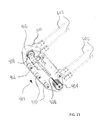
- FIG. 11 is a cut-away perspective view of components of the embodiment of the workstation depicted in FIG. 9 in accordance with the present disclosure.
- FIG. 12 is a perspective view of components of an embodiment of a workstation in accordance with the present disclosure.
- FIG. 13 is an exploded view of components of the embodiment of the workstation depicted in FIG. 12 in accordance with the present disclosure.
- FIG. 14 is a perspective view of components of an embodiment of a workstation in accordance with the present disclosure.
- FIG. 15 is a perspective view of components of an embodiment of a workstation in accordance with the present disclosure.
- FIG. 16 is an exploded perspective view of components of the embodiment of the workstation depicted in FIG. 15 in accordance with the present disclosure.
- FIG. 17 is an exploded perspective view of components of an embodiment of a workstation in accordance with the present disclosure.
- FIG. 18 is an exploded perspective view of components of the embodiment of the workstation depicted in FIG. 17 in accordance with the present disclosure.
- FIG. 19 is an exploded perspective view of components of the embodiment of the workstation depicted in FIG. 17 in accordance with the present disclosure.
- FIG. 20 is a perspective view of components of an embodiment of a workstation in accordance with the present disclosure.
- FIG. 21 is a schematic view of a method of using embodiments of the workstation in accordance with the present disclosure.
- FIG. 22 is a schematic view of an operation of an embodiment of a workstation in accordance with the present disclosure.
- FIGS. 1-3 depict perspective views, respectively, illustrating vertical climbing workstation apparatus 100 at rest, preceding use on columnar object 120 in FIG. 1 , and workstation 100 in use, on columnar object 120 in FIG. 2 , and workstation 100 not surrounding a columnar object 120 , all according to embodiments of the present disclosure.
- Workstation apparatus 100 is shown in FIG. 1 in a non-employed position 104 .
- Workstation apparatus 100 is resting on ground 102 , surrounding the base of tree 122 as would be realized during a typical setup or dismantle process.
- FIG. 2 illustrates workstation apparatus 100 in employed-position 204 in use on utility pole 222 .
- FIG. 3 depicts a perspective view of an embodiment of the workstation 100 .
- a vertical climbing workstation apparatus 100 comprises an adjustable frame 140 , a powered drive system 130 , an adjustable suspension system 160 , and a remote control 170 that may be operated by a user 110 .
- portions of the workstation apparatus 100 are shown separate from columnar object 120 to provide an unobstructed view of the relation between these components of the workstation apparatus 100 .
- the overall design of the workstation apparatus 100 is targeted at durability for longevity, cost-effectiveness in use and to protect the user 110 from unnecessary risk during repair or maintenance tasks.
- the workstation apparatus 100 is shown in pre-use and in-use in FIGS. 1 and 2 , respectively.
- the workstation apparatus 100 may comprise a variety of sizes and shapes and be manufactured from various materials.
- the workstation apparatus 100 is grounded and/or comprises non-conductive materials to insulate user 110 from electrical shock. Moreover, by the user 110 being remotely positioned from the workstation 100 while operating the workstation 100 via remote control, the user 110 is also separated, or otherwise removed, from the possibility of electric shock.
- the workstation 100 may be powered by on-board battery power, via one or more batteries 9 positioned on the workstation 100 , and operated via one or more wireless controllers that communicate wirelessly with the control unit 8 on the workstation 100 , the control unit 8 comprising a computer system, including, but not limited to, for example, a processor (CPU), an internal storage unit, random access memory (RAM), software, a network card, alternative inputs for a keyboard, mouse, joystick or other input device, a motherboard, and components, such as receivers and transmitters, for sending and receiving wireless signals.
- the computer system herein described is configured to control the operational aspects of the workstation 100 .
- the software may be a computer program that is developed and configured to operate the workstation 100 according to its intended operation, as described herein.
- control unit 8 may be utilized to control the adjustable frame 140 , the powered drive system 150 , the camera(s) 108 , the arm 106 , the compressor 7 , the individual motors, the tool 5 and the tool holder 312 , and other operational aspects of the workstation 100 , as depicted in FIG. 22 .
- the workstation 100 may be powered by batteries 9 positioned remotely from the workstation 100 and the workstation may be controlled, or otherwise operated, via a combined power supply and a wired controller, such as, for example, a wiring harness.
- the adjustable frame 140 of workstation apparatus 100 may be offset from and surround an entire exterior circumference of the columnar object 120 , such as the tree 122 as shown in FIG. 1 or the utility pole 222 of FIG. 2 , to which adjustable frame 140 may be functionally and removably coupled.
- the workstation may also be powered by pneumatic control or hydraulic control as will be herein described.
- embodiments of the workstation 100 may include the adjustable frame 140 and can be manufactured from square or rectangular tubing for cost-effectiveness in manufacturing.
- the adjustable frame 140 may comprise one or more corner sections 145 and an adjustable rail 139 coupled between consecutive cornering sections 145 .
- the adjustable rail 139 may further comprise at least one frame expansion housing 142 and a corresponding frame expansion rod 143 that is inserted therein and is configured to move therein.
- the adjustable frame 140 may be adapted and configured to be expandable and contractible using at least one frame expansion housing 142 and a corresponding frame expansion rod 143 , wherein the frame expansion rod 143 may move with respect to the frame expansion housing 142 to thereby allow workstation apparatus 100 to expand or retract in size, as needed.
- standard wireless feedback sensors may be positioned on the workstation 100 to sense the changing diameter or changing surface conditions of the columnar object 120 as the workstation 100 travels along the axis of the columnar object 120 .
- the adjustable frame 140 may be configured to allow the frame expansion rods 143 and the frame expansion housing 142 to move with respect to one another in response to the feedback from the sensors to adjust the size of the adjustable frame 140 .
- the sensors may communicate with the control unit 8 to instruct the adjustable frame 140 to automatically expand in response to the increasing diameter of the columnar object 120 .
- the sensors may communicate with the control unit 8 to instruct the adjustable frame 140 to automatically retract in response to the decreasing diameter of the columnar object 120 .
- the workstation 100 is adaptable to be fitted around columnar objects 120 of varying dimensions and perimeters of round and semi-round profiles.
- one or more frame expansion rods 143 may be decoupled from or coupled to corner sections 145 , so as to permit the one or more frame expansion rods 143 to detach from the workstation 100 to allow the workstation 100 to be taken off of and transported away from the columnar object 120 .
- the corner section 145 may further comprise vertical support beams 146 and horizontal support beams 147 .
- the vertical support beams 146 may have attached thereto the horizontal support beams 147 on each distal end thereof.
- the vertical support beams 146 may further comprise powered drive system mounts 131 thereon to support the functional operation of the powered drive system 130 .
- Each of the mounts 131 may have a through bore therein 131 a .
- the corner section 145 may further comprise a bracket mount 148 .
- the bracket mount 148 may be configured to receive and releasably couple thereto a bracket 149 that may be configured to receive and releasably couple thereto an arm base 107 that may be configured to receive and releasably couple thereto a semi-robotic arm 106 , to be discussed in greater detail below.
- the corner section 145 may further comprise one or more corner frame couplers 180 , wherein each of the corner frame couplers 180 may be configured to receive a corresponding frame expansion end cap 143 c positioned on a distal end of a frame expansion rod 143 , as depicted in FIGS. 6-8 .
- Embodiments of the workstation 100 include the coupler 180 being operated to functionally engage the end cap 143 c to thereby secure the frame expansion rod 143 to the corner section 145 via the mechanical locking relationship between the coupler 180 and the corresponding end cap 143 c.
- each of the couplers 180 may further comprise a body 181 , one or more pins 188 , a quick release member 190 , and a securing ring 194 .
- the body 181 may be further comprised of a securing member 181 a and a circular portion 181 b .
- the securing member 181 a may be configured to engage a corresponding horizontal support beam 147 of the corner section 145 .
- the support beam 147 may be hollow.
- the support beam 147 and the securing member 181 a may be configured to have corresponding shapes, such that the securing member 181 a may be inserted within the hollow portion of the support beam 147 .
- the securing member 181 a may be fixedly coupled to the support beam 147 , such that the support beam 147 supports and secures thereto the coupler body 181 .
- the circular portion 181 b may further comprise engagement openings 184 positioned at regular intervals around the circumference of the outer surface of the circular portion 181 b .
- the circular portion 181 b may also comprise slits 186 in the outer surface positioned at regular intervals.
- the circular portion 181 b may also comprise holes 187 positioned in the outer surface positioned at regular intervals.
- the circular portion 181 b may be configured to define a hollow cavity 185 therein.
- the engagement openings 184 may be configured to extend completely through the circular portion 181 b and into the hollow cavity 185 .
- the slits 186 and the holes 187 may also be configured to extend completely through the circular portion 181 b.
- Each of the pins 188 may be comprised of a pin head 188 a and a pin tail 188 b .
- Each of the pins 188 may be configured to engage the outer surface of the circular portion 181 b , such that the pin head 188 a of one of the pins 188 may engage a corresponding engagement opening 184 .
- the pin tail 188 b of one of the pins 188 may be configured to engage a corresponding slit 186 . In this way, each of the pins 188 may be anchored to the circular portion 181 b while at the same time allowing the pin head 188 a of each of the pins 188 to slidably engage the axial opening of the engagement opening 184 .
- the pin head 188 a may be configured to be circular in shape to correspond to the circular shape of the engagement opening 184 .
- the pin tail 188 b may be configured to flex, or otherwise bend, to allow the pin head 188 a to move in or out of the engagement opening 184 in response to force applied to the pin 188 .
- a quick release member 190 may be configured to engage each of the pins 188 on the circular portion 181 b , as well as rotatably communicate with the circular portion 181 b .
- the quick release member 190 may be configured to have a throughbore therein, the throughbore being configured to fit over and functionally communicate with the outer surface of the circular portion 181 b and the pins 188 .
- the quick release member 190 may have an internal indention 191 along the inside circumference of the quick release member 190 .
- the internal indention 191 may be configured to functionally engage, and house, the pins 188 , including the pin tail 188 b and the pin head 188 a of each of the pins 188 .
- the internal indention 191 may further comprise one or more graduated depressions 192 therein.
- the graduated depressions 192 may be configured to communicate with the pins 188 , such that at the deepest point of the graduated depression 192 , the pin head 188 a does not functionally engage the engagement opening 184 , or at least does not pass completely through the circular portion 181 b and into the hollow cavity 185 . In this position, the pin head 188 a is in a non-engaged position, which purpose will be described hereinafter in greater detail. At the shallowest point of the graduated depression 192 , the pin head 188 a functionally engages the engagement opening 184 and passes completely through the circular portion 181 b and into the hollow cavity 185 .
- the quick release member 190 may be rotated about the circular portion 181 b to transition the pins 188 from the deepest portion of the graduated depression 192 to the shallowest portion of the graduated depression 192 to transition the pin head 188 a from the non-engaged position to the engaged position, respectively.
- the quick release member 190 may be rotated about the circular portion 181 b to transition the pins 188 from the shallowest portion of the graduated depression 192 to the deepest portion of the graduated depression 192 to transition the pin head 188 a from the engaged position to the non-engaged position, respectively.
- the rotational movement of the quick release member 190 may be repeatedly performed to transition the pins 188 between their respective engaged and non-engaged positions.
- the securing ring 194 may be configured to functionally engage the circular portion 181 b and function to maintain the engagement of the quick release member 190 on the circular portion 181 b .
- the securing ring 194 may have holes 195 that are configured to correspond to the holes 187 in the circular portion 181 b , such that a fastener (now shown) may be inserted through the holes 195 and 187 to secure the securing ring 194 to the circular portion 181 b.
- the end cap 143 c of the frame expansion rod 143 may be configured to repeatedly and releasably couple to the coupler 180 on the corner section 145 .
- the end cap 143 c may be configured with engagement ports 184 a that are positioned at regular intervals around the outer circumference of the end cap 143 c .
- the engagement ports 184 a may be configured to correspond to the engagement openings 184 in the circular portion 181 b .
- the engagement ports 184 a may be configured to likewise receive a corresponding pin head 188 a that has been forcibly inserted completely through the engagement opening 184 under the condition that the pins 188 are in the engaged position.
- the pin head 188 a of each of the pins 188 functionally engages both the engagement opening 184 of the circular portion 181 b and the respective engagement port 184 a in the end cap 143 c .
- the pins 188 function to functionally engage the frame expansion rod 143 to the corner section 145 , via the mechanical and functional engagement of the end cap 143 c and the coupler 180 .
- the pins 188 release the end cap 143 c from the coupler 180 and permit the frame expansion rod 143 to be removed from the corner section 145 .
- the simple operation of rotating the quick release member 190 about the circular portion 181 b permits the pins 188 to transition easily and quickly between an engaged position and a non-engaged position to easily and quickly release or couple, as the case may be, the frame expansion rods 143 to the corner sections 145 .
- This quick release design permits the user 110 to quickly and easily assemble or disassemble the workstation 100 form around the columnar object 100 .
- the workstation 100 may comprise the adjustable rail 139 .
- the adjustable rail 139 may further comprise a frame expansion housing 142 and one or more corresponding frame expansion rods 143 .
- Embodiments of the workstation 100 include the frame expansion housing 142 being hollow in portions thereof to permit each of the frame expansion rods 143 to partially reside therein.
- portions of the frame expansion rods 143 may reside within the hollow portion of the frame expansion housing 142 and other portions of the frame expansion rods 143 may reside outside of the housing 142 .
- FIG. 7 shows the housing 142 in dotted lines, to reveal the interior of the housing 142 , such that the portions of the frame expansion rods 143 that are within the frame expansion housing 142 are visible within the housing.
- the frame expansion rods 143 may be configured to functionally engage the hollow portion of the housing 142 .
- a frame expansion rod head 143 a may be coupled to a distal end portion of the frame expansion rod 143 that is placed within the hollow portions of the frame expansion housing 142 .
- the frame expansion rod head 143 a may be configured to slidably engage, or otherwise communicate with, the interior surface of the hollow frame expansion housing 142 .
- a head seal 143 b may be placed over the rod head 143 a to seal the communication between the frame expansion rod 143 and the interior of the frame expansion housing 142 , such that an airtight chamber 141 c is established.
- a frame expansion housing cap 142 a may be coupled to an end portion of the frame expansion housing 142 , or otherwise fixed with respect to the frame expansion housing 142 , and the frame expansion housing cap 142 a may be configured to slidably engage, or otherwise communicate with, the frame expansion rod 143 .
- the housing cap 142 a may be a linear bearing that permits the slidable communication between the expansion rod 143 and the housing 142 .
- a cap seal 142 b may be positioned against the internal side of the housing cap 142 a , such that the seal 142 b completes the airtight chamber 141 c mentioned above.
- the head seal 143 b and the cap seal 142 b each communicate with the interior surface of the housing 142 to create the airtight chamber 141 c within the housing 142 between the cap seal 142 b and the head seal 143 b.
- the expansion rod head 143 a may be further configured to prevent the expansion rod 143 from disengaging from the frame expansion housing 142 , such that the frame expansion rod head 143 a remains within the housing 142 .
- the expansion housing cap 142 a may be manually removed from the housing 142 to allow the frame expansion rod 143 to disengage and be removed from the housing 142 , if desired by the user, for maintenance and repair, or the like.
- the frame expansion rods 143 may pneumatically communicate with the frame housing 142 .
- an air line 141 a and an air valve 141 b may be provided to facilitate pneumatic communication between the frame expansion rods 143 and the interior of the frame housing 142 .
- Air within an air tank may be compressed in a compressor 7 , and the resulting high-pressure air may flow through the air valve 141 b and through the air line 141 a and into the airtight chamber 141 c created between each set of the cap seal 142 b and the head seal 143 b .
- Air pressure may be increased by flowing air into the airtight chamber 141 c to push against both the frame expansion rod head 143 a and the housing cap 142 a to force the frame expansion rod 143 to move axially inward with respect to the housing 142 .
- the force of the pressure causes the frame expansion rod head 143 a and the housing cap 142 a to move apart from one another, which reduces the length of the frame expansion rod 143 that extends outside the housing 142 , which reduces the overall length of the adjustable rail 139 .
- air pressure may be reduced by flowing air out of the airtight chamber 141 c to reduce the force against both the frame expansion rod head 143 a and the housing cap 142 a to allow the frame expansion rod 143 to move axially outward with respect to the housing 142 .
- the reduced force of the pressure causes the frame expansion rod head 143 a and the housing cap 142 a to move toward one another, which increases the length of the frame expansion rod 143 that extends outside the housing 142 , which increases the overall length of the adjustable rail 139 .
- such a pneumatic configuration may be used to fix the positional relationship between the frame expansion rods 143 and the interior of the frame housing 142 , as determined by the user 110 , to adjust the overall length of the adjustable rail 139 as determined by the diameter or size of the columnar object 120 on which the workstation 100 is mounted.
- the pneumatic configuration may be used to fix the positional relationship between the frame expansion rods 143 and the interior of the frame housing 142 , as determined by wireless communication with the operator's computerized control unit, the computer program controlling the pressure to achieve the desired movement within predetermined parameters, making this function transparent to the user except when attaching or removing the workstation 100 from a columnar object 120 .
- the outward pressure and movement of the adjustable rail 139 is provided by the columnar object 120 and is communicated to the frame expansion rods 143 via the push back pressure of the columnar object 120 on the powered drive system 130 which is attached to the frame corner assemblies 145 to which the adjustable rails 139 are attached via the locking mechanism between the coupler 180 and the end cap 143 c .
- the respective tracked climbers 150 of the powered drive system 130 pushes against the respective corner sections 145 to which the tracked climbers 150 are functionally coupled.
- the adjustable rail 139 may need to adjust to maintain the tracked climbers 150 on the columnar object 120 . Therefore, sensors on the workstation 100 communicate with the control unit 8 which communicates with the air compressor which communicates with the airtight chamber 141 c which adjusts the length of the adjustable rail 139 .
- the pressurized interior of the airtight chamber 141 c may be depressurized to manually adjust the frame expansion rods 143 with respect to the housing 142 or to disengage the frame expansion rods 143 from the housing 142 .
- the pressurized interior of the airtight chamber 141 c may alternatively be automatically adjusted to adjust the frame expansion rods 143 with respect to the housing 142 or to disengage the frame expansion rods 143 from the housing 142 .
- the automatic adjustment of the size of each of the adjustable rails 139 may be facilitated by feedback received by the powered drive system 130 . To maintain the powered drive system 130 in contact with the columnar object 120 , the adjustable rail 139 may need to automatically adjusted, as described above, in real time to accommodate for the changing diameter of the columnar object 120 .
- hydraulic or mechanical means may be utilized to automatically or manually adjust and fix the positional relationship between the frame expansion rods 143 and the interior of the frame housing 142 , as described herein. In fact, the structural configuration above provides that.
- embodiments of the workstation 100 further comprise a powered drive system 130 coupled thereto.
- the powered drive system 130 may further comprise one or more tracked climbers 150 , as depicted in FIGS. 9-11 , that work together to result in the workstation 100 being able to ascend and descend on the columnar object 120 .
- Columnar objects 120 may be inconsistent with respect to the circumference size, such as the tree 122 that may narrow from bottom to top of the tree 122 .
- the columnar object 120 may have many surface variations such as knots, small limbs, bark irregularities, and other such conditions.
- the powered drive system 130 may be configured to accommodate for these inconsistent irregularities.
- a tracked climber 150 comprises a track 412 , enclosure panels 500 , and rails 602 .
- the track 412 may be supported and oriented between opposing enclosure panels 500 and configured to move therebetween, as will be described in greater detail below.
- the enclosure panels 500 are configured to releasably and lockably enclose each vertical side of track-climber 150 , as shown in FIGS. 8 and 9 .
- Enclosure panels 500 are preferably held in place using removable fasteners, not shown.
- the rails 602 may extend from the panels 500 and may be configured to engage the through bore 131 a on the mount 131 to functionally engage the tracked climber 150 with the adjustable frame 140 .
- Each of the through bores 131 a may be configured to house a linear bearing therein that helps facilitate the functional communication of the rails 602 with the respective through bore 131 a .
- Each rail 602 may be configured to engage a corresponding through bore 131 a .
- each rail 602 may be configured to slidably engage its corresponding through bore 131 a , such that the rails 602 may slide back and forth within the corresponding through bore 131 a but not completely detach, or otherwise disengage, therefrom, unless of course the user 110 manually disengages the rails 602 from within the through bore 131 a , as needed.
- the configuration of the rails 602 and the corresponding through bores 131 a may permit each tracked climber 150 to move toward or away from the columnar object 120 in response to the contours, irregularities, and other variations in the surface of the columnar object 120 , as discussed above. Moreover, the configuration of the rails 602 and the corresponding through bores 131 a may restrict the side-to-side movement of the tracked climber 150 to maintain the track 412 of each tracked climber 150 more or less centered on the columnar object 120 , despite the contours, irregularities, and other variations in the surface of the columnar object 120 discussed above.
- Embodiments of the tracked climber 150 include the track 412 comprising grips 414 , which can be oriented in any direction on the track 412 .
- Embodiments of the tracked climber 150 include the grips 414 being oriented transverse to the direction of motion of the track 412 .
- the grips 414 may run parallel with the direction of motion of the track 412 .
- embodiments of the tracked climber 150 include the grips 414 being positioned on the track 412 in arbitrary locations and positions, or on the other hand, in a repeated pattern on the track 412 .
- the grips 414 may be configured on the track 412 in a continuous or repeated manner or in an arbitrary manner, and the grips 414 may have the same or varying patterns, designs, shapes, profiles, and sizes with respect to one another to facilitate adequate gripping of the track 412 on the columnar object 120 .
- the track 412 may be interchangeable from one tracked climber 150 to another by removing one of the panels 500 and removing the track 412 .
- individual tracks 412 with varying grips 414 can be interchanged in the tracked climber 150 for use in the workstation 100 depending upon the surface characteristics of the columnar object 120 on which the workstation 100 will be used, as determined by the user 110 .
- embodiments of the workstation 100 include the tracked-climber 150 further comprising a motor 402 , a gear set 404 , a power pulley 408 , and a plurality of idler pulleys 410 housed within the tracked-climber 150 and between opposing enclosure panels 500 (one of which is removed in the embodiment depicted in FIG. 11 , so as to expose the inner components of the tracked-climber 150 ).
- the motor 402 may be configured to drive a gear shaft 405 that drives the gear set 404 .
- the motor 402 may be configured to drive the gear shaft 405 in a clockwise or counterclockwise rotation, thus controlling the movement of the workstation 100 , as described herein.
- the motor 402 may be AC or DC electrically controlled, hydraulically-controlled, or pneumatically-controlled, depending on preference of user 110 , or the desired work application. Under the condition that the motor 402 is electrically controlled, the motor 402 may be powered by on-board batteries 9 or through the wiring harness described herein.
- the electrical motor 402 may be configured to provide rotational motion to the gear shaft 405 , which thus powers the gear set 404 , which thus provides rotational motion to the power pulley 408 , which thus provides motion to the track 412 to control the movement of the workstation 100 , as described herein. As depicted in FIG.
- the motor 402 may be pneumatically powered and may further comprise an air vane 403 that may be configured within the motor 402 and may be further configured to receive high pressure air therein from the compressor 7 to rotate the air vane 403 to provide rotational motion to the gear shaft 405 , which thus powers the gear set 404 , which thus provides rotational motion to the power pulley 408 , which thus provides motion to the track 412 to control the movement of the workstation 100 , as described herein.
- the gear set 404 may be configured to comprise one or more gears 406 that transfer rotational motion of the motor 402 to rotational motion of the power pulley 408 .
- the gears 406 may comprise a worm gear set 407 a and a helical gear set 407 b that function to communicate rotational motion of the motor 402 to rotational motion of the power pulley 408 .
- the worm gear set 407 a may be coupled to a distal end of the shaft 405 , such that as the shaft 405 rotates, so too does the worm gear set 407 a .
- the worm gear set 407 a may also be in mechanical communication with the helical gear set 407 b , such that as the worm gear set 407 a rotates, so too does the helical gear set 407 b .
- the helical gear set 407 b may be in mechanical communication with a pulley drive shaft 416 , such that as the helical gear set 407 b rotates, so too does the pulley drive shaft 416 .
- the pulley drive shaft 416 may be in mechanical communication with the power pulley 408 , such that as the pulley drive shaft 416 rotates, so too does the power pulley 408 .
- the gears 406 function to transfer rotational motion of the motor 402 to rotational motion of the power pulley 408 .
- Embodiments of the tracked-climber 150 further comprise the motor 402 , the gear set 404 and the power pulley 408 being engaged and held in place by a first-side drive carriage 422 and a second-side drive carriage 424 that are configured to secure to one another with the motor 402 , the gear set 404 , and at least a power pulley 408 being housed therebetween.
- the carriages 422 and 424 may be functionally coupled to the tracked-climber 150 .
- a tension member 426 may be coupled to one or more of the power pulleys 408 .
- the tension member 426 may be configured to maintain the positional relationship between opposing power pulleys 408 .
- the tension member 426 may further be configured to increase or decrease the distance between opposing power pulleys 408 to respectively increase or decrease the tension of the track 412 that travels about the power pulleys 408 and the idler pulleys 410 .
- the power pulley 408 may be further configured to comprise one or more friction members 409 on the surface thereof, such as ridges or elevations on the outer surface of the power pulley that function to grip the interior surface of the track 412 .
- the friction members 409 of the power pulley 408 function to enhance the frictional contact between the power pulley 408 and the interior surface of the track 412 , such that the rotational movement of the power pulley 408 causes the track 412 to move tangentially in relation to the rotational movement of the power pulley 408 and to the idler pulleys 410 .
- the motor 402 and the gears 406 are configured to drive the track 412 in a clockwise or counterclockwise rotation about the power pulley 408 .
- the resulting rotation of the track 412 and the frictional contact of the track 412 when placed against the columnar object 120 results in the workstation 100 being configured, or otherwise adapted, to ascend or descend the columnar object 120 . Further, movement of the workstation 100 with respect to the columnar object 120 , i.e., upward or downward movement, is a result of the direction the track 412 is rotated.
- the configuration of the three drive system in a triangle formation causes the workstation 100 to automatically self-center on columnar objects 120 , even when the columnar object 120 may be oriented at any angle with respect to the surface from which the columnar object 120 extends.
- the enclosure panels 500 comprise durable and tough material to be reliable in service.
- the enclosure panels 500 are configured to keep debris out of the interior of tracked-climber 150 to protect the track 412 , the motor 402 , the gear set 404 , the power pulleys 408 , the idler pulley 410 , and any other interior component from prematurely wearing.
- the enclosure panels 500 further comprise mounting holes 504 , as shown, and bearing seats. The bearing seats are provided to accommodate idler pulleys 410 .
- the profile of the enclosure panels 500 and mounting holes 504 may be changed to permit different sizes and combinations of the tracked-climbers 150 or different sizes and combinations of the powered drive system 130 .
- embodiments of the workstation 100 include the adjustable suspension system 160 .
- the adjustable suspension system 160 comprises one or more adjustable linear actuators 604 that can be functionally coupled to the workstation 100 between the adjustable frame 140 and each of the tracked climbers 150 .
- Embodiments of the workstation 100 include the linear actuators 604 being, for example and not by way of limitation, a gas spring shock absorber, or other like shock absorber.
- the linear actuator 604 may be placed, respectively, between the upper and lower pairs of rails 602 on the tracked climber 150 , such that each tracked climber 150 is configured to have one or more linear actuator 604 paired with the upper pair of rails 602 and one or more linear actuator 604 paired with the lower pair of rails 602 to permit the tracked climber 150 to adjust to the contours of the columnar object 120 , as needed.
- the configuration and placement of the actuators 604 between the tracked climber 150 and the adjustable frame 140 permits the each linear actuator 604 to independently react to the varying contours and irregularities on the surface of the columnar object 120 to keep the respective track 412 of each tracked climber 150 in contact with the columnar object 120 as the workstation 100 ascends or descends the columnar object 120 .
- the adjustable suspension system 160 secures and manipulates each tracked-climber 150 of powered drive system 130 to accommodate for differences in contours on columnar object 120 while workstation apparatus 100 is ascending on the surface of columnar object 120 .
- the required pressure is independently exerted on each of the actuators 604 positioned near the upper and lower pairs of rails 602 .
- each of the actuators 604 exerts the required force and also reacts independently to the surface irregularities of the columnar object 120 to keep the respective track 412 against the columnar object 120 by providing the necessary force against the columnar object 120 .
- the actuators 604 press the track 412 against the columnar object near portion 413 of the tracked-climber 150 .
- each of the tracked-climbers 150 may adjust according to the contours of the columnar object 120 .
- the contact angle and contact area (footprint) of track 412 on tracked-climbers 150 can self-adjust against the surface of the columnar object according to the varying contours of columnar object 120 to keep the portion 413 of the track 412 up against the columnar object 120 .
- Such frictional force exerted by linear actuators 604 on the tracked-climbers 150 causes the track 412 to press against the columnar object 120 to maintain the workstation 100 in a desired position against the object 120 .
- the force exerted by the linear actuators 604 is not so great as to prevent the tracked-climbers 150 from adjusting in real time to the contours of the columnar object 120 .
- the linear actuators 604 are configured to move back and forth, in and out, to keep the track 412 of the tracked-climber 150 up against the surface of the columnar object 120 .
- Operation of the track 412 in either direction also causes the workstation 100 to ascend or descend the columnar object 120 .
- the speed of rotation of the track 412 can be adjusted by adjusting the rotational speed of the power pulley 408 via the motor 402 , according to user 110 preference and/or preset limits supplied to the motor 402 via the wired or wireless control station operated by the user.
- Embodiments of the workstation 100 include a remote control 170 that may be manipulated by user 110 to control the operation of the workstation 100 .
- the remote control 170 may be wired or wireless.
- the remote control 170 may be utilized to instruct the system 160 to immediately release, or otherwise retract, from the surface of the columnar object 120 to permit the workstation 100 to rapidly descend down the columnar object 120 , and in some cases to free fall from the columnar object 120 .
- emergency, non-powered descents are possible with the workstation 100 by allowing the suspension system 160 to be released via the remote control 170 .
- Embodiments of the workstation 100 include one or more adjustable rotatable wheels 116 .
- the workstation 100 may include one or more wheels 116 that swivel, one wheel 116 coupled to each corner of the frame 140 , as depicted in FIG. 14 .
- the wheels 116 may be releasable, or otherwise detachable from the workstation 100 once the workstation 100 is secured to the columnar object 120 and may be recoupled to the workstation 100 when preparing to move the workstation to another location or to another columnar object 120 .
- Other suitable rotatable mechanisms such as casters may also be used.
- the wheels 116 may be adjusted vertically to level the workstation apparatus 100 , as well as provide a means to easily move and position the workstation apparatus 100 when on the ground 102 .
- Embodiments of the workstation 100 include a mounting surface 112 on adjustable frame 140 , as depicted in FIG. 1 , adapted to secure at least one semi-robotic arm 106 which may further comprise at least one camera 108 mounted thereon.
- the camera(s) 108 may be configured to be wired or wireless.
- the camera 108 preferably uses virtual reality feedback, thus providing the user 110 the ability to position the robotic arm 106 in real-time.
- Each camera 108 may be configured to send the views to both a virtual reality type of head gear worn by the operator and also to a monitor mounted and sized appropriately to the operator's remote control station.
- the camera 108 can be used to allow user 110 to view and potentially visually record the work that is performed by the robotic arm 106 , in both semi-robotic and robotic states of the arm, because the operator directly controls the arm via wireless or wired remote control station with a joystick and/or other switches as various job applications require the direct control by the operator.
- Camera 108 may be wired or wireless, and camera 108 may be powered by on-board batteries 9 or through the wiring harness described herein.
- embodiments of the workstation 100 include brackets 149 on corner sections 145 that may be configured to receive and releasably couple thereto an arm base 107 that may be configured to receive and releasably couple thereto the semi-robotic arm 106 , as discussed herein.
- the semi-robotic arm 106 may be mounted on workstation apparatus 100 , as depicted in FIGS. 1-3 and 15 .
- the semi-robotic arm 106 may be operated by the user 110 using a wired or wireless version of the remote control 170 .
- at least one camera 108 may be operated in embodiments of the present disclosure and may be mounted to semi-robotic arm 106 using camera mounting bracket 308 , as depicted.
- the camera 108 can be used to allow the user 110 to view the work being performed by the camera 108 transmitting images and/or video in real time to a monitor or screen (not shown), such that the user 110 can view the images and/or video.
- the camera 108 can also visually record any work done by the semi-robotic arm 106 in real-time.
- the camera 108 may also be configured to transmit digital data, either wirelessly or through wires, to a remote viewing device, such as a smart phone or other similar device, or to a hard drive or memory storage device positioned either on the workstation 100 or remotely therefrom.
- a remote viewing device such as a smart phone or other similar device
- a hard drive or memory storage device positioned either on the workstation 100 or remotely therefrom.
- embodiments of the workstation 100 include the semi-robotic arm 106 being mounted to workstation apparatus 100 .
- embodiments of the workstation 100 include the arm 106 being releasably coupled to the workstation 100 through engagement of the arm base 107 with the bracket 149 .
- Embodiments of the workstation 100 include the arm base 107 further comprising a tube 103 and a tube casing 105 , the tube casing 105 being configured to slidably and rotationally engage the tube 103 .
- the tube 103 may be configured to be hollow and may also be configured to have sidewall openings 103 a therein, to provide access to the hollow interior space of the tube 103 .
- the sidewall openings 103 a may be on either side of the tube 103 , such that the tube 103 has several sidewall openings 103 a therein, some of the sidewall openings 103 a being on opposite sides of the tube 103 , whereas other sidewall openings 103 a are arranged in parallel with one another along an axial length of the tube 103 .
- the casing 105 may be configured to be hollow and may also be configured to have sidewall openings 105 a therein, to provide access to the hollow interior space of the casing 105 .
- the sidewall openings 105 a may be on either side of the casing 105 , such that the casing 105 has several sidewall openings 105 a therein, some of the sidewall openings 105 a being on opposite sides of the casing 105 , whereas other sidewall openings 105 a are arranged in parallel with one another along an axial length of the tube 105 , as depicted in FIG. 16 . Because the tube 103 and the casing 105 are hollow, components of the workstation 100 may be stored therein, such as, for example, and not by way of limitation, the on-board battery 9 , the air tank, the air compressor 7 , the computer system, and other workstation components.
- these components may functionally communicate with their respective components located on other portions of the workstation 100 , such as, for example, the air compressor 7 communicating through the air valve 141 d and through the air line 141 c with the frame expansion housing 142 and a corresponding frame expansion rod 143 , as described herein.
- the user 110 may rotate the casing 105 to align the sidewall openings 105 a with the sidewall openings 103 a of the tube 103 to access the interior of the tube 103 and the workstation components housed therein to repair, monitor, upgrade, and/or replace, as needed, these components.
- the tube 103 and the tube casing 105 may be manufactured of lightweight and sturdy materials, such as, for example, light-weight metals, plastics, and polymers, such as carbon fiber.
- embodiments of the workstation 100 include the arm 106 further comprising one or more appendages 390 , one or more joints 350 , the arm base 107 described herein, and a tool holder 312 .
- the appendages 390 may further comprise an inner tube member 392 and an outer casing 394 that may be configured to slidably engage the inner tube member 392 .
- Embodiments of the workstation 100 include the outer casing 394 completely covering the inner tube member 392 .
- the inner tube member 392 may be hollow to provide an interior space for housing therein wiring components, compressed air lines, and/or other components, including a rotation assembly 370 to be described herein.
- the inner tube member 392 may have sidewall openings 392 a therein to provide access to the hollow interior.
- the inner tube member 392 and the outer casing 394 may be manufactured of lightweight and sturdy materials, such as, for example, light-weight metals, plastics, and polymers, such as carbon fiber.
- embodiments of the workstation 100 include the joints 350 being configured between each consecutive appendage 390 , between the arm base 107 and an appendage 390 , and between an appendage 390 and the tool holder 312 .
- Each of the joints 350 may further comprise one or both of a pivot assembly 352 and a rotation assembly 370 .
- the pivot assembly 352 may be configured to provide pivoting motion to the joint 350
- the rotation assembly 370 may be configured to provide rotational motion to the joint 350 .
- Each joint 350 may have one or more pivot assemblies 352 or one or more rotational assemblies 370 .
- embodiments of the workstation 100 may further comprise a pivot assembly 352 .
- the pivot assembly 352 may further comprise opposing braces 354 and 362 that may be configured to engage one another with the remaining pivot assembly 352 components housed therebetween.
- the braces 354 and 362 are releasably coupled to their respective appendages 390 , such that one appendage 390 is releasably coupled to the brace 354 and another appendage 390 is coupled to the brace 362 , as depicted in FIG. 17 .
- the pivot assembly 352 may further comprise a bearing assembly 356 , a motor 358 , and gears 360 .
- the bearing assembly 356 , the motor 358 , and the gears 360 may be aligned along a common axis of rotation defined by a pin 364 that also functions to secure the pivot assembly 352 together.
- the bearing assembly 356 , the motor 358 , and the gears 360 may be configured about the axis defined by the axis of the pin 364 .
- the motor 358 may provide rotational motion to the pivot assembly 352 by way of the gears 360 .
- the motor 358 may be electrically powered, pneumatically powered, or hydraulically powered.
- the motor 358 is a pneumatically powered motor that further comprises air vanes therein that are configured to receive compressed air and translate the flow of the compressed air into rotational force. This rotational force is then transferred to the gears 360 .
- the gears 360 transfer this rotational motion to one of the braces 354 or 362 , such that one of these braces 354 and 362 rotates with respect to the other to cause the joint 350 to pivot in a range of at least 180 degrees.
- the bearing assembly 356 functions to facilitate the rotation of the braces 354 and 362 with respect to one another.
- the bearing assembly 356 may comprise one or more thrust bearings 356 a and a needle bearing configuration 356 b .
- One thrust bearing 356 a may be positioned between the motor 358 and the gears 360 .
- Another thrust bearing 356 a may be positioned between a plate 356 d housed against the brace 354 and a cap 356 e that is configured to cap the needle bearing 356 a within a needle bearing housing 356 c such that the needle bearing 356 a resides within the needle bearing housing 356 c .
- the needle bearing 356 b may communicate with the needle bearing housing 356 c and the motor 358 . In certain embodiments, the needle bearing 356 b may reside between the needle bearing housing 356 c and the motor 358 .
- embodiments of the workstation 100 may further comprise a rotation assembly 370 .
- the rotation assembly 370 may further comprise a base 372 , a motor housing 374 , a motor 376 , and a planetary gear set 378 .
- the base 372 may be configured to releasably couple to the brace 362 .
- the base 372 may also be configured to engage the motor housing 374 .
- the motor housing 374 may be configured to house the motor 376 .
- the motor 376 may provide rotational force to the rotation assembly 370 .
- the motor 376 may be electrically powered, pneumatically powered, or hydraulically powered.
- the motor 376 is a pneumatically powered motor that further comprises air vanes 377 therein that are configured to receive compressed air and translate the flow of the compressed air into rotational force.
- the resulting rotational force of the motor 376 is transferred to the planetary gear set 378 to drive the central gear 380 .
- the central gear 380 thereafter drives the outer gear 382 through the relationship of the outer gear 382 and the central gear 380 in the planetary gear set 378 .
- the outer gear 382 may be configured with bores 384 that are configured to correspond to the openings 396 in both the tube 392 and the casing 394 , such that the appendage 390 may be releasably coupled to the bores 384 of the outer gear 382 .
- each appendage 390 likewise rotates.
- the central gear 380 may be configured to rotate at least 360 degrees in a clockwise or counterclockwise rotation, thus causing the outer gear 382 to rotate in a corresponding manner, in either a clockwise or counterclockwise rotation.
- each appendage 390 is configured to rotate through 360 degrees, as needed.
- each joint 350 may provide pivoting motion of 180 degrees in either a clockwise or counterclockwise direction and may provide rotational motion through 360 degrees in either a clockwise or counterclockwise direction.
- each rotation joint 370 and each pivot joint 352 of each joint 350 may be independently controlled by the user 110 via the control unit 8 and the controller 170 , such that the arm 106 may be positioned in any number of positions, configurations, and orientations.
- embodiments of the workstation 100 further comprise a tool holder 312 .
- the tool holder 312 may comprise an engagement member 316 , a safety lock mechanism 318 , and an access port 322 .
- the tool holder 312 may be configured to releasably and repeatedly couple thereto tools (not shown), such as, for example, saws, blades, shears, grippers, clippers, and other tools needed to trim, cut, or otherwise administer pruning to, tree limbs and other portions of trees.
- the tool holder 312 may comprise an engagement member 316 that may be configured to functionally engage the tools coupled to the tool holder 312 .
- the various tools that are to be coupled to the tool holder 312 may be engaged by the tool holder 312 via the engagement member 316 .
- the engagement member 316 may be threads that correspond to threads on the tools to be attached to the tool holder 312 .
- the tool holder 312 may further comprise a safety lock mechanism 318 .
- the safety lock mechanism 318 may be configured to receive pins (not shown) on the tools to be coupled to the tool holder 312 .
- the safety lock mechanism 318 may be configured to have a slit 319 in the sidewall of the tool holder 312 .
- the slit 319 may be configured to receive and functionally engage the corresponding pins of the tools to be coupled to the tool holder 312 .
- the safety lock mechanism 318 may serve as additional coupling of the tool to the tool holder 312 , in addition to the coupling of the tool to the tool holder 312 via the mechanical engagement of the engagement member 316 .
- the configuration of the tool holder 312 and the semi-robotic arm 106 permits the tool that is coupled to the tool holder 312 to reach into and access difficult spots, positions, angles, crevices, and other like parts of the columnar object 120 , to perform various tasks while in those spots, including, but not limited to, the tasks of pruning, shearing, clipping, etc.
- the tool holder 312 may comprise an access port 322 that provides access for cables, electric cables, pneumatic air lines, and other power lines or communication lines through the tool holder 312 to power the tool.
- the tool that is to be coupled to the tool holder 312 may require power and/or communication with the control unit 8 , the compressor 7 , or the battery 9 , as needed, to function properly.
- These cables, lines, or other similar components may be fed from their respective sources, usually found in the arm base 107 , through the joints 350 and hollow appendages 390 of the arm 106 up through the tool holder 312 and to the tool.
- these lines can communicate with any of the components of the arm 106 as these lines travel up to the tool in the tool holder 312 .
- compressed air from the compressor 7 in the arm base 107 may be fed up through the appendages of the arm 106 to each of the joints 350 to drive the motors 358 and 376 , as well as drive the operation of the tool.
- electrical wires from the on-board battery 9 may be fed in a similar manner to provide power to the joints 350 , if the motors 358 and 376 are electric motors, and to provide power to the camera 108 and the tool in the tool holder 312 .
- the semi-robotic arm 106 may further comprise the following components: sensors, dust seal(s), bearing(s), attachment sleeve(s), appropriate gearing, thrust bearing(s), motor(s), motor securing bracket(s) and other suitable parts to enable the semi-robotic arm 106 to rotate along a plurality of axis at its various joints. Sensors may be included within the joints 350 of the semi-robotic arm 106 to provide feedback of the position of each appendage 390 to the user 110 . It should be noted that the specific semi-robotic arm 106 , as shown and described in the present figure, is not intended to be limited to the various combinations, configurations and uses disclosed herein. It should be realized that other equivalent means to achieve the same purpose may be employed to perform the same or similar task(s).
- the workstation apparatus 100 is very versatile and may be used for assisting in tasks ranging from de-limbing of the tree 122 and/or working to service the utility wire 224 on the utility pole 222 or other such tall columnar objects 120 that may be difficult and dangerous to reach.
- workstation apparatus 100 is designed to essentially remove the user 110 from the danger of working in hazardous environments such as next to the utility wires 224 and at dangerous heights above the ground 102 , thereby enabling the tasks to be performed from a safe distance.
- Workstation apparatus 100 may be used to readily perform a range of tasks from trimming or de-limbing as previously mentioned to disconnecting and/or reconnecting the utility wire 224 as shown in FIGS. 1 and 2 .
- a method of use 700 is depicted according to an embodiment of the workstation 100 .
- the method comprises unlocking the adjustable frame of workstation apparatus 701 ; placing workstation apparatus around columnar object 702 , as shown in FIG. 1 ; fine-tune positioning workstation apparatus using rotatable wheels 703 .
- step 703 is an optional step and may not be implemented in all cases.
- Other optional steps of method 700 are also illustrated using dotted lines in FIG. 21 so as to distinguish them from the other steps of method 700 .
- the method further comprises locking adjustable frame of workstation apparatus 704 .
- Such locking can occur by activating the compressor 7 to flow high pressure air into the adjustable rails 139 to fix the adjustable rails 139 in place, such that the adjustable frame 140 is fixed, or otherwise locked, into position.
- the method further comprises bringing the tracked-climbers of the powered drive system into contact with the columnar object 705 ; activating tracks of said track-climbers in a forward motion allowing workstation apparatus to ascend columnar object 706 ; locking workstation apparatus in place and performing the desired tasks on columnar object using semi-robotic arm and camera(s) 707 ; reversing power to the tracks to allow workstation apparatus to descend columnar object 708 ; unlocking adjustable frame 709 ; and removing workstation apparatus from around columnar object 710 .
- Additional or clarifying method steps include the following: placing the workstation apparatus around a columnar object, bringing tracked-climbers of a powered drive system into contact with the columnar object using a remote control, activating tracks of the tracked-climbers to control ascension and decent of the workstation with respect to the columnar object, and performing tasks on the columnar object.
- the method of use for the vertical climbing workstation apparatus 100 further includes, removing an adjustable rail from a frame of the workstation apparatus to place the workstation apparatus around the columnar object, replacing the adjustable rail in the frame after the workstation apparatus has been placed around the columnar object, adjusting the adjustable rail to expand or contract the frame, operating the tracked-climbers by remote control to control the ascension and decent of the workstation apparatus on the columnar object, performing tasks on the columnar object using a semi-robotic arm having a tool and a camera attached thereto, retracting the tracks from the columnar object to allow the workstation to descend rapidly from the columnar object, operating the tracked-climbers to control the descent of the columnar object until the columnar object reaches a ground surface, removing the adjustable rail to remove the workstation apparatus from around the columnar object, and removing the workstation from around the columnar object.
- Retracting the tracks from the columnar object may further comprise reducing the pressure of the actuators for a controlled descent along the columnar object, whereas in emergency situations the full depressurization of the actuators allows the workstation to freefall or rapidly descend the object to which it is attached.
Landscapes
- Engineering & Computer Science (AREA)
- Life Sciences & Earth Sciences (AREA)
- Mechanical Engineering (AREA)
- Robotics (AREA)
- Structural Engineering (AREA)
- Biodiversity & Conservation Biology (AREA)
- Automation & Control Theory (AREA)
- Ecology (AREA)
- Forests & Forestry (AREA)
- Environmental Sciences (AREA)
- Civil Engineering (AREA)
- Computer Networks & Wireless Communication (AREA)
- Transportation (AREA)
- Rehabilitation Tools (AREA)
Abstract
An apparatus designed for climbing poles, trees and other such columnar objects. The apparatus is a remote-controlled work station that provides a scaffold for mounting semi-robotic articulated arms and video cameras. The articulated arm has a quick-release coupler on an end thereof that is able to repeatedly and releasably couple attachments thereto, such as saws, blades, and other pruning objects. The device includes an expandable frame that may be opened and closed to fit around the vertical structure to be climbed. The frame has horizontal and vertical supports, drive system compression supports, and wheels. A drive system is mounted to each of the drive system compression supports. The drive system includes motorized tracked-climbers that are maintained in contact with the vertical structure to be climbed via adjustable independent suspension. The suspension uses adjustable spring shocks and drive system slide rails to connect the frame to the drive system.
Description
- Technical Field
- This disclosure relates generally to the field of workstations and more specifically relates to remote-controlled workstations.
- State of the Art
- Problems emerge when tall, natural and artificial objects need to be installed, maintained or repaired. Many natural columnar objects such as trees, especially palm trees, also require maintenance tasks such as de-limbing or cutting palm fronds to be performed at various intervals. Trees normally present a problem to persons attempting to perform tasks requiring ascending and descending, since tree trunks are not typically uniform in thickness or in surface consistency and may have limbs and other obstacles that may impede such endeavors.
- In addition to trees, artificial structures such as those used to support above-ground utility and communication lines often require periodic or regular maintenance. The service of these structures and lines may cause persons to undergo undue risk from falling from great heights, electrocution from high-voltage electric lines, or other such inherent dangers.
- Safety equipment may be provided to protect persons from falling hazards; however the equipment may be expensive, restrictive and uncomfortable for a user to wear. Further, the safety equipment such as for example, a safety harness may only provide minimal protection against falling hazards and offer no protection against electrocution should the user come into contact with a live electrical wire.
- Scaffolding may be used as a means to work on columnar objects; however scaffolding is not conducive to portability and still leaves the person at risk to accidents from contact and falling injuries. Further, the scaffolding requires significant set-up and teardown time which may be expensive and time-consuming.
- Ideally, a workstation would be stable, would separate users from many of the dangers described above, would require minimal maintenance, would operate safely and reliably, and would be manufactured at a modest expense. Thus, a need exists for a workstation to protect workers from dangerous conditions and to avoid the above-mentioned problems.
- The present invention relates to the field of workstations and more specifically relates to remote-controlled workstations.
- An aspect of the present disclosure includes a vertical climbing workstation apparatus, the workstation apparatus comprising a frame, a powered drive system functionally coupled to the frame, a suspension system functionally coupled to the powered drive system, wherein the powered drive system is configured to engage a columnar object and under the condition that the powered drive system is operated the vertical climbing workstation apparatus moves with respect to the columnar object.
- Another aspect of the present disclosure includes the columnar object having one end thereof embedded in a surface and an opposing end thereof that extends from the surface, and wherein the workstation apparatus is adapted to travel along the centrally located axis of the columnar object.
- Another aspect of the present disclosure includes the frame further comprising an adjustable rail and one or more corner sections, the adjustable rail being functionally coupled between neighboring corner sections, the adjustable rail being adapted to adjust the distance between neighboring corner sections to adjust the frame.
- Another aspect of the present disclosure includes the frame being configured to removably surround the columnar object and configured to be offset from the columnar object, and wherein the powered drive system engages the columnar object.
- Another aspect of the present disclosure includes the adjustable suspension system being functionally coupled between the frame and the powered drive system and wherein the adjustable suspension system supports the powered drive system against columnar object.
- Another aspect of the present disclosure includes the adjustable suspension system further comprising a linear actuator that is adapted to adjust the positional relationship between the powered drive system and the frame to support the powered drive system against the columnar object as the powered drive system engages irregularities on the columnar object.
- Another aspect of the present disclosure includes the adjustable suspension system being retractable to release the powered drive system from the columnar object to allow rapid descent of the workstation apparatus from the columnar object
- Another aspect of the present disclosure includes the apparatus being configured to be operated by a user remotely positioned from the apparatus, the apparatus being controlled by a control unit in communication with a remote control operated by the user.
- Another aspect of the present disclosure includes a semi-robotic arm, the semi-robotic arm being releasably coupled to the frame and the semi-robotic arm comprising one or more appendages functionally coupled together in succession by a joint therebetween.
- Another aspect of the present disclosure includes the joint further comprising a pivot assembly and a rotation assembly, wherein the pivot assembly provides pivoting motion between successive appendages with respect to one another and wherein the rotation assembly provides rotational motion between successive appendages with respect to one another.
- Another aspect of the present disclosure includes the semi-robotic arm further comprising a tool holder for engaging a tool.
- Another aspect of the present disclosure includes the semi-robotic arm further comprising a camera for observing the tool.
- Another aspect of the present disclosure includes the workstation apparatus comprising an adjustable frame having adjustable rails configured to expand or contract to adjust dimensions of the adjustable frame, a powered drive system functionally coupled to the frame, the powered drive system having a tracked-climber, and a suspension system functionally coupled between the powered drive system and the adjustable frame, wherein the tracked-climber is configured to engage a columnar object and under the condition that the powered drive system is operated the workstation apparatus moves with respect to the columnar object.
- Another aspect of the present disclosure includes the tracked-climber further comprising a motor, a gear set functionally engaged by the motor, a power pulley functionally engaged by the gear set, and a track functionally engaged by the power pulley, wherein the motor provides power to rotate the gear set to provide rotation to the power pulley, wherein the rotation of the power pulley causes the track to move tangentially in relation to the power pulley, and wherein the tangential movement of the track results in the workstation apparatus traveling along the axis of the columnar object.
- Another aspect of the present disclosure includes the powered drive system comprising three tracked-climbers individually coupled to the frame.
- Another aspect of the present disclosure includes each of the tracked-climbers being coupled to a respective suspension system and each suspension system being configured to support the corresponding tracked-climber against the columnar object as the workstation apparatus ascends and descends the columnar object and thereby engages irregularities in the columnar object.
- Another aspect of the present disclosure includes the motor being pneumatically, hydraulically, or electrically controlled.
- Another aspect of the present disclosure includes the tracked-climber further comprising a tensioning member that is adapted to adjust a tension of the track.
- Another aspect of the present disclosure includes a method of use for a vertical climbing workstation apparatus comprising, placing the workstation apparatus around a columnar object, bringing tracked-climbers of a powered drive system into contact with the columnar object using a remote control, activating tracks of the tracked-climbers to control ascension and decent of the workstation with respect to the axis of the columnar object, and performing tasks on the columnar object.
- Another aspect of the present disclosure includes the method of use for a vertical climbing workstation apparatus further comprising, removing an adjustable rail from a frame of the workstation apparatus to place the workstation apparatus around the columnar object, replacing the adjustable rail in the frame after the workstation apparatus has been placed around the columnar object, adjusting the adjustable rail to expand or contract the frame, operating the tracked-climbers by remote control to control the ascension and decent of the workstation apparatus on the columnar object, performing tasks on the columnar object using a semi-robotic arm having a tool and a camera attached thereto, retracting the tracks from the columnar object to allow the workstation to descend rapidly from the columnar object, operating the tracked-climbers to control the descent of the columnar object until the columnar object reaches a ground surface, removing the adjustable rail to remove the workstation apparatus from around the columnar object, and removing the workstation from around the columnar object.
- The foregoing and other features, advantages, and construction of the present disclosure will be more readily apparent and fully appreciated from the following more detailed description of the particular embodiments, taken in conjunction with the accompanying drawings.
- Some of the embodiments will be described in detail, with reference to the following figures, wherein like designations denote like members:
-
FIG. 1 is a perspective view of an embodiment of a workstation in accordance with the present disclosure. -
FIG. 2 is a perspective view of an embodiment of a workstation in accordance with the present disclosure. -
FIG. 3 is a perspective view of components of an embodiment of a workstation in accordance with the present disclosure. -
FIG. 4 is a perspective view of components of an embodiment of a workstation in accordance with the present disclosure. -
FIG. 5A is a perspective view of components of an embodiment of a workstation in accordance with the present disclosure. -
FIG. 5B is an exploded view of a component of an embodiment of a workstation in accordance with the present disclosure. -
FIG. 6 is a perspective view of components of an embodiment of a workstation in accordance with the present disclosure. -
FIG. 7 is a perspective view of components of the embodiment of the workstation depicted inFIG. 6 in accordance with the present disclosure. Thehousing 142 is shown in broken- or dotted-lines to reveal the interior of thehousing 142. -
FIG. 8 is an exploded view of components of the embodiment of the workstation depicted inFIGS. 6 and 7 in accordance with the present disclosure. -
FIG. 9 is a perspective view of components of an embodiment of a workstation in accordance with the present disclosure. -
FIG. 10 is a perspective view of components of the embodiment of the workstation depicted inFIG. 9 in accordance with the present disclosure. -
FIG. 11 is a cut-away perspective view of components of the embodiment of the workstation depicted inFIG. 9 in accordance with the present disclosure. -
FIG. 12 is a perspective view of components of an embodiment of a workstation in accordance with the present disclosure. -
FIG. 13 is an exploded view of components of the embodiment of the workstation depicted inFIG. 12 in accordance with the present disclosure. -
FIG. 14 is a perspective view of components of an embodiment of a workstation in accordance with the present disclosure. -
FIG. 15 is a perspective view of components of an embodiment of a workstation in accordance with the present disclosure. -
FIG. 16 is an exploded perspective view of components of the embodiment of the workstation depicted inFIG. 15 in accordance with the present disclosure. -
FIG. 17 is an exploded perspective view of components of an embodiment of a workstation in accordance with the present disclosure. -
FIG. 18 is an exploded perspective view of components of the embodiment of the workstation depicted inFIG. 17 in accordance with the present disclosure. -
FIG. 19 is an exploded perspective view of components of the embodiment of the workstation depicted inFIG. 17 in accordance with the present disclosure. -
FIG. 20 is a perspective view of components of an embodiment of a workstation in accordance with the present disclosure. -
FIG. 21 is a schematic view of a method of using embodiments of the workstation in accordance with the present disclosure. -
FIG. 22 is a schematic view of an operation of an embodiment of a workstation in accordance with the present disclosure. - A detailed description of the hereinafter described embodiments of the disclosed apparatus and method are presented herein by way of exemplification and not limitation with reference to the Figures listed above. Although certain embodiments are shown and described in detail, it should be understood that various changes and modifications may be made without departing from the scope of the appended claims. The scope of the present disclosure will in no way be limited to the number of constituting components, the materials thereof, the shapes thereof, the relative arrangement thereof, etc., and are disclosed simply as an example of embodiments of the present disclosure.
- As a preface to the detailed description, it should be noted that, as used in this specification and the appended claims, the singular forms “a”, “an” and “the” include plural referents, unless the context clearly dictates otherwise.
- Referring to the drawings,
FIGS. 1-3 depict perspective views, respectively, illustrating verticalclimbing workstation apparatus 100 at rest, preceding use oncolumnar object 120 inFIG. 1 , andworkstation 100 in use, oncolumnar object 120 inFIG. 2 , andworkstation 100 not surrounding acolumnar object 120, all according to embodiments of the present disclosure.Workstation apparatus 100 is shown inFIG. 1 in anon-employed position 104.Workstation apparatus 100 is resting onground 102, surrounding the base oftree 122 as would be realized during a typical setup or dismantle process.FIG. 2 illustratesworkstation apparatus 100 in employed-position 204 in use onutility pole 222.FIG. 3 depicts a perspective view of an embodiment of theworkstation 100. - A vertical
climbing workstation apparatus 100 according to the present disclosure comprises anadjustable frame 140, apowered drive system 130, anadjustable suspension system 160, and aremote control 170 that may be operated by auser 110. As depicted inFIG. 3 , portions of theworkstation apparatus 100 are shown separate fromcolumnar object 120 to provide an unobstructed view of the relation between these components of theworkstation apparatus 100. The overall design of theworkstation apparatus 100 is targeted at durability for longevity, cost-effectiveness in use and to protect theuser 110 from unnecessary risk during repair or maintenance tasks. Theworkstation apparatus 100 is shown in pre-use and in-use inFIGS. 1 and 2 , respectively. Theworkstation apparatus 100 may comprise a variety of sizes and shapes and be manufactured from various materials. Ideally, theworkstation apparatus 100 is grounded and/or comprises non-conductive materials to insulateuser 110 from electrical shock. Moreover, by theuser 110 being remotely positioned from theworkstation 100 while operating theworkstation 100 via remote control, theuser 110 is also separated, or otherwise removed, from the possibility of electric shock. - The
workstation 100 may be powered by on-board battery power, via one ormore batteries 9 positioned on theworkstation 100, and operated via one or more wireless controllers that communicate wirelessly with thecontrol unit 8 on theworkstation 100, thecontrol unit 8 comprising a computer system, including, but not limited to, for example, a processor (CPU), an internal storage unit, random access memory (RAM), software, a network card, alternative inputs for a keyboard, mouse, joystick or other input device, a motherboard, and components, such as receivers and transmitters, for sending and receiving wireless signals. The computer system herein described is configured to control the operational aspects of theworkstation 100. For example, the software may be a computer program that is developed and configured to operate theworkstation 100 according to its intended operation, as described herein. In embodiments of theworkstation 100, thecontrol unit 8 may be utilized to control theadjustable frame 140, thepowered drive system 150, the camera(s) 108, thearm 106, thecompressor 7, the individual motors, thetool 5 and thetool holder 312, and other operational aspects of theworkstation 100, as depicted inFIG. 22 . - Alternatively, the
workstation 100 may be powered bybatteries 9 positioned remotely from theworkstation 100 and the workstation may be controlled, or otherwise operated, via a combined power supply and a wired controller, such as, for example, a wiring harness. Theadjustable frame 140 ofworkstation apparatus 100 may be offset from and surround an entire exterior circumference of thecolumnar object 120, such as thetree 122 as shown inFIG. 1 or theutility pole 222 ofFIG. 2 , to whichadjustable frame 140 may be functionally and removably coupled. The workstation may also be powered by pneumatic control or hydraulic control as will be herein described. - As depicted in
FIGS. 3-4 , embodiments of theworkstation 100 may include theadjustable frame 140 and can be manufactured from square or rectangular tubing for cost-effectiveness in manufacturing. Theadjustable frame 140 may comprise one ormore corner sections 145 and anadjustable rail 139 coupled between consecutive corneringsections 145. Theadjustable rail 139 may further comprise at least oneframe expansion housing 142 and a correspondingframe expansion rod 143 that is inserted therein and is configured to move therein. For example, theadjustable frame 140 may be adapted and configured to be expandable and contractible using at least oneframe expansion housing 142 and a correspondingframe expansion rod 143, wherein theframe expansion rod 143 may move with respect to theframe expansion housing 142 to thereby allowworkstation apparatus 100 to expand or retract in size, as needed. For example, standard wireless feedback sensors may be positioned on theworkstation 100 to sense the changing diameter or changing surface conditions of thecolumnar object 120 as theworkstation 100 travels along the axis of thecolumnar object 120. For example, theadjustable frame 140 may be configured to allow theframe expansion rods 143 and theframe expansion housing 142 to move with respect to one another in response to the feedback from the sensors to adjust the size of theadjustable frame 140. The sensors may communicate with thecontrol unit 8 to instruct theadjustable frame 140 to automatically expand in response to the increasing diameter of thecolumnar object 120. Conversely, the sensors may communicate with thecontrol unit 8 to instruct theadjustable frame 140 to automatically retract in response to the decreasing diameter of thecolumnar object 120. In this way, theworkstation 100 is adaptable to be fitted aroundcolumnar objects 120 of varying dimensions and perimeters of round and semi-round profiles. Moreover, one or moreframe expansion rods 143 may be decoupled from or coupled to cornersections 145, so as to permit the one or moreframe expansion rods 143 to detach from theworkstation 100 to allow theworkstation 100 to be taken off of and transported away from thecolumnar object 120. - As depicted in
FIG. 5 , thecorner section 145 may further comprise vertical support beams 146 and horizontal support beams 147. The vertical support beams 146 may have attached thereto the horizontal support beams 147 on each distal end thereof. The vertical support beams 146 may further comprise powered drive system mounts 131 thereon to support the functional operation of thepowered drive system 130. Each of themounts 131 may have a through bore therein 131 a. Thecorner section 145 may further comprise abracket mount 148. Thebracket mount 148 may be configured to receive and releasably couple thereto abracket 149 that may be configured to receive and releasably couple thereto anarm base 107 that may be configured to receive and releasably couple thereto asemi-robotic arm 106, to be discussed in greater detail below. - As depicted in
FIG. 5A , thecorner section 145 may further comprise one or morecorner frame couplers 180, wherein each of thecorner frame couplers 180 may be configured to receive a corresponding frameexpansion end cap 143 c positioned on a distal end of aframe expansion rod 143, as depicted inFIGS. 6-8 . Embodiments of theworkstation 100 include thecoupler 180 being operated to functionally engage theend cap 143 c to thereby secure theframe expansion rod 143 to thecorner section 145 via the mechanical locking relationship between thecoupler 180 and thecorresponding end cap 143 c. - As depicted in
FIG. 5B , each of thecouplers 180 may further comprise abody 181, one ormore pins 188, aquick release member 190, and a securingring 194. Thebody 181 may be further comprised of a securingmember 181 a and a circular portion 181 b. The securingmember 181 a may be configured to engage a correspondinghorizontal support beam 147 of thecorner section 145. Thesupport beam 147 may be hollow. Thesupport beam 147 and the securingmember 181 a may be configured to have corresponding shapes, such that the securingmember 181 a may be inserted within the hollow portion of thesupport beam 147. Thereafter, the securingmember 181 a may be fixedly coupled to thesupport beam 147, such that thesupport beam 147 supports and secures thereto thecoupler body 181. On the other hand, the circular portion 181 b may further compriseengagement openings 184 positioned at regular intervals around the circumference of the outer surface of the circular portion 181 b. The circular portion 181 b may also comprise slits 186 in the outer surface positioned at regular intervals. The circular portion 181 b may also compriseholes 187 positioned in the outer surface positioned at regular intervals. The circular portion 181 b may be configured to define a hollow cavity 185 therein. Theengagement openings 184 may be configured to extend completely through the circular portion 181 b and into the hollow cavity 185. The slits 186 and theholes 187 may also be configured to extend completely through the circular portion 181 b. - Each of the
pins 188 may be comprised of a pin head 188 a and a pin tail 188 b. Each of thepins 188 may be configured to engage the outer surface of the circular portion 181 b, such that the pin head 188 a of one of thepins 188 may engage acorresponding engagement opening 184. Likewise, the pin tail 188 b of one of thepins 188 may be configured to engage a corresponding slit 186. In this way, each of thepins 188 may be anchored to the circular portion 181 b while at the same time allowing the pin head 188 a of each of thepins 188 to slidably engage the axial opening of theengagement opening 184. The pin head 188 a may be configured to be circular in shape to correspond to the circular shape of theengagement opening 184. The pin tail 188 b may be configured to flex, or otherwise bend, to allow the pin head 188 a to move in or out of theengagement opening 184 in response to force applied to thepin 188. - A
quick release member 190 may be configured to engage each of thepins 188 on the circular portion 181 b, as well as rotatably communicate with the circular portion 181 b. Thequick release member 190 may be configured to have a throughbore therein, the throughbore being configured to fit over and functionally communicate with the outer surface of the circular portion 181 b and thepins 188. Thequick release member 190 may have aninternal indention 191 along the inside circumference of thequick release member 190. Theinternal indention 191 may be configured to functionally engage, and house, thepins 188, including the pin tail 188 b and the pin head 188 a of each of thepins 188. Theinternal indention 191 may further comprise one or moregraduated depressions 192 therein. The graduateddepressions 192 may be configured to communicate with thepins 188, such that at the deepest point of the graduateddepression 192, the pin head 188 a does not functionally engage theengagement opening 184, or at least does not pass completely through the circular portion 181 b and into the hollow cavity 185. In this position, the pin head 188 a is in a non-engaged position, which purpose will be described hereinafter in greater detail. At the shallowest point of the graduateddepression 192, the pin head 188 a functionally engages theengagement opening 184 and passes completely through the circular portion 181 b and into the hollow cavity 185. In this position, the pin head 188 a is in an engaged position, which purpose will be described hereinafter in greater detail. Thus, thequick release member 190 may be rotated about the circular portion 181 b to transition thepins 188 from the deepest portion of the graduateddepression 192 to the shallowest portion of the graduateddepression 192 to transition the pin head 188 a from the non-engaged position to the engaged position, respectively. Likewise, thequick release member 190 may be rotated about the circular portion 181 b to transition thepins 188 from the shallowest portion of the graduateddepression 192 to the deepest portion of the graduateddepression 192 to transition the pin head 188 a from the engaged position to the non-engaged position, respectively. The rotational movement of thequick release member 190 may be repeatedly performed to transition thepins 188 between their respective engaged and non-engaged positions. - The securing
ring 194 may be configured to functionally engage the circular portion 181 b and function to maintain the engagement of thequick release member 190 on the circular portion 181 b. The securingring 194 may haveholes 195 that are configured to correspond to theholes 187 in the circular portion 181 b, such that a fastener (now shown) may be inserted through theholes ring 194 to the circular portion 181 b. - As previously mentioned, the
end cap 143 c of theframe expansion rod 143 may be configured to repeatedly and releasably couple to thecoupler 180 on thecorner section 145. Theend cap 143 c may be configured withengagement ports 184 a that are positioned at regular intervals around the outer circumference of theend cap 143 c. Theengagement ports 184 a may be configured to correspond to theengagement openings 184 in the circular portion 181 b. As such, theengagement ports 184 a may be configured to likewise receive a corresponding pin head 188 a that has been forcibly inserted completely through theengagement opening 184 under the condition that thepins 188 are in the engaged position. As suggested, in the engagedposition 188, the pin head 188 a of each of thepins 188 functionally engages both theengagement opening 184 of the circular portion 181 b and therespective engagement port 184 a in theend cap 143 c. In this way, in the engaged position, thepins 188 function to functionally engage theframe expansion rod 143 to thecorner section 145, via the mechanical and functional engagement of theend cap 143 c and thecoupler 180. In the non-engaged position, thepins 188 release theend cap 143 c from thecoupler 180 and permit theframe expansion rod 143 to be removed from thecorner section 145. As a result of the above, the simple operation of rotating thequick release member 190 about the circular portion 181 b permits thepins 188 to transition easily and quickly between an engaged position and a non-engaged position to easily and quickly release or couple, as the case may be, theframe expansion rods 143 to thecorner sections 145. This quick release design permits theuser 110 to quickly and easily assemble or disassemble theworkstation 100 form around thecolumnar object 100. - As depicted in
FIG. 6 , theworkstation 100 may comprise theadjustable rail 139. Theadjustable rail 139 may further comprise aframe expansion housing 142 and one or more correspondingframe expansion rods 143. Embodiments of theworkstation 100 include theframe expansion housing 142 being hollow in portions thereof to permit each of theframe expansion rods 143 to partially reside therein. For example, as depicted inFIG. 7 , portions of theframe expansion rods 143 may reside within the hollow portion of theframe expansion housing 142 and other portions of theframe expansion rods 143 may reside outside of thehousing 142.FIG. 7 shows thehousing 142 in dotted lines, to reveal the interior of thehousing 142, such that the portions of theframe expansion rods 143 that are within theframe expansion housing 142 are visible within the housing. Theframe expansion rods 143 may be configured to functionally engage the hollow portion of thehousing 142. For example, as depicted inFIGS. 7 and 8 , a frameexpansion rod head 143 a may be coupled to a distal end portion of theframe expansion rod 143 that is placed within the hollow portions of theframe expansion housing 142. The frameexpansion rod head 143 a may be configured to slidably engage, or otherwise communicate with, the interior surface of the hollowframe expansion housing 142. Ahead seal 143 b may be placed over therod head 143 a to seal the communication between theframe expansion rod 143 and the interior of theframe expansion housing 142, such that an airtight chamber 141 c is established. Further in example, a frameexpansion housing cap 142 a may be coupled to an end portion of theframe expansion housing 142, or otherwise fixed with respect to theframe expansion housing 142, and the frameexpansion housing cap 142 a may be configured to slidably engage, or otherwise communicate with, theframe expansion rod 143. For example, thehousing cap 142 a may be a linear bearing that permits the slidable communication between theexpansion rod 143 and thehousing 142. In this way, theframe expansion rod 143 and theframe expansion housing 142 may move with respect to one another. A cap seal 142 b may be positioned against the internal side of thehousing cap 142 a, such that the seal 142 b completes the airtight chamber 141 c mentioned above. Specifically, thehead seal 143 b and the cap seal 142 b each communicate with the interior surface of thehousing 142 to create the airtight chamber 141 c within thehousing 142 between the cap seal 142 b and thehead seal 143 b. - The
expansion rod head 143 a may be further configured to prevent theexpansion rod 143 from disengaging from theframe expansion housing 142, such that the frameexpansion rod head 143 a remains within thehousing 142. Of course, theexpansion housing cap 142 a may be manually removed from thehousing 142 to allow theframe expansion rod 143 to disengage and be removed from thehousing 142, if desired by the user, for maintenance and repair, or the like. - The
frame expansion rods 143 may pneumatically communicate with theframe housing 142. As depicted inFIGS. 7 and 8 , an air line 141 a and an air valve 141 b may be provided to facilitate pneumatic communication between theframe expansion rods 143 and the interior of theframe housing 142. Air within an air tank may be compressed in acompressor 7, and the resulting high-pressure air may flow through the air valve 141 b and through the air line 141 a and into the airtight chamber 141 c created between each set of the cap seal 142 b and thehead seal 143 b. Air pressure may be increased by flowing air into the airtight chamber 141 c to push against both the frameexpansion rod head 143 a and thehousing cap 142 a to force theframe expansion rod 143 to move axially inward with respect to thehousing 142. In other words, as the pressure inside the airtight chamber 141 c is increased, the force of the pressure causes the frameexpansion rod head 143 a and thehousing cap 142 a to move apart from one another, which reduces the length of theframe expansion rod 143 that extends outside thehousing 142, which reduces the overall length of theadjustable rail 139. Similarly, air pressure may be reduced by flowing air out of the airtight chamber 141 c to reduce the force against both the frameexpansion rod head 143 a and thehousing cap 142 a to allow theframe expansion rod 143 to move axially outward with respect to thehousing 142. In other words, as the pressure inside the airtight chamber 141 c is decreased, the reduced force of the pressure causes the frameexpansion rod head 143 a and thehousing cap 142 a to move toward one another, which increases the length of theframe expansion rod 143 that extends outside thehousing 142, which increases the overall length of theadjustable rail 139. Accordingly, such a pneumatic configuration may be used to fix the positional relationship between theframe expansion rods 143 and the interior of theframe housing 142, as determined by theuser 110, to adjust the overall length of theadjustable rail 139 as determined by the diameter or size of thecolumnar object 120 on which theworkstation 100 is mounted. Further, the pneumatic configuration may be used to fix the positional relationship between theframe expansion rods 143 and the interior of theframe housing 142, as determined by wireless communication with the operator's computerized control unit, the computer program controlling the pressure to achieve the desired movement within predetermined parameters, making this function transparent to the user except when attaching or removing theworkstation 100 from acolumnar object 120. - In embodiments of the
workstation 100, the outward pressure and movement of theadjustable rail 139 is provided by thecolumnar object 120 and is communicated to theframe expansion rods 143 via the push back pressure of thecolumnar object 120 on thepowered drive system 130 which is attached to theframe corner assemblies 145 to which theadjustable rails 139 are attached via the locking mechanism between thecoupler 180 and theend cap 143 c. In other words, as pressure is produced by thecolumnar object 120 on thepowered drive system 130, the respective trackedclimbers 150 of thepowered drive system 130 pushes against therespective corner sections 145 to which the trackedclimbers 150 are functionally coupled. As pressure is thus exerted on thecorner sections 145, theadjustable rail 139 may need to adjust to maintain the trackedclimbers 150 on thecolumnar object 120. Therefore, sensors on theworkstation 100 communicate with thecontrol unit 8 which communicates with the air compressor which communicates with the airtight chamber 141 c which adjusts the length of theadjustable rail 139. - The pressurized interior of the airtight chamber 141 c may be depressurized to manually adjust the
frame expansion rods 143 with respect to thehousing 142 or to disengage theframe expansion rods 143 from thehousing 142. The pressurized interior of the airtight chamber 141 c may alternatively be automatically adjusted to adjust theframe expansion rods 143 with respect to thehousing 142 or to disengage theframe expansion rods 143 from thehousing 142. The automatic adjustment of the size of each of theadjustable rails 139 may be facilitated by feedback received by thepowered drive system 130. To maintain thepowered drive system 130 in contact with thecolumnar object 120, theadjustable rail 139 may need to automatically adjusted, as described above, in real time to accommodate for the changing diameter of thecolumnar object 120. In a similar manner, hydraulic or mechanical means may be utilized to automatically or manually adjust and fix the positional relationship between theframe expansion rods 143 and the interior of theframe housing 142, as described herein. In fact, the structural configuration above provides that. - As depicted in
FIGS. 1-3 , embodiments of theworkstation 100 further comprise apowered drive system 130 coupled thereto. Thepowered drive system 130 may further comprise one or more trackedclimbers 150, as depicted inFIGS. 9-11 , that work together to result in theworkstation 100 being able to ascend and descend on thecolumnar object 120. Columnar objects 120 may be inconsistent with respect to the circumference size, such as thetree 122 that may narrow from bottom to top of thetree 122. In addition, thecolumnar object 120 may have many surface variations such as knots, small limbs, bark irregularities, and other such conditions. As a result, thepowered drive system 130 may be configured to accommodate for these inconsistent irregularities. - As depicted in
FIGS. 9-11 , a trackedclimber 150 comprises atrack 412,enclosure panels 500, and rails 602. Thetrack 412 may be supported and oriented between opposingenclosure panels 500 and configured to move therebetween, as will be described in greater detail below. Theenclosure panels 500 are configured to releasably and lockably enclose each vertical side of track-climber 150, as shown inFIGS. 8 and 9 .Enclosure panels 500 are preferably held in place using removable fasteners, not shown. Therails 602 may extend from thepanels 500 and may be configured to engage the throughbore 131 a on themount 131 to functionally engage the trackedclimber 150 with theadjustable frame 140. Each of the throughbores 131 a may be configured to house a linear bearing therein that helps facilitate the functional communication of therails 602 with the respective throughbore 131 a. Eachrail 602 may be configured to engage a corresponding throughbore 131 a. Moreover, eachrail 602 may be configured to slidably engage its corresponding throughbore 131 a, such that therails 602 may slide back and forth within the corresponding throughbore 131 a but not completely detach, or otherwise disengage, therefrom, unless of course theuser 110 manually disengages therails 602 from within the throughbore 131 a, as needed. The configuration of therails 602 and the corresponding throughbores 131 a may permit each trackedclimber 150 to move toward or away from thecolumnar object 120 in response to the contours, irregularities, and other variations in the surface of thecolumnar object 120, as discussed above. Moreover, the configuration of therails 602 and the corresponding throughbores 131 a may restrict the side-to-side movement of the trackedclimber 150 to maintain thetrack 412 of each trackedclimber 150 more or less centered on thecolumnar object 120, despite the contours, irregularities, and other variations in the surface of thecolumnar object 120 discussed above. - Embodiments of the tracked
climber 150 include thetrack 412 comprisinggrips 414, which can be oriented in any direction on thetrack 412. Embodiments of the trackedclimber 150 include thegrips 414 being oriented transverse to the direction of motion of thetrack 412. Alternatively, as depicted, thegrips 414 may run parallel with the direction of motion of thetrack 412. Moreover, embodiments of the trackedclimber 150 include thegrips 414 being positioned on thetrack 412 in arbitrary locations and positions, or on the other hand, in a repeated pattern on thetrack 412. Indeed, thegrips 414 may be configured on thetrack 412 in a continuous or repeated manner or in an arbitrary manner, and thegrips 414 may have the same or varying patterns, designs, shapes, profiles, and sizes with respect to one another to facilitate adequate gripping of thetrack 412 on thecolumnar object 120. Additionally, thetrack 412 may be interchangeable from one trackedclimber 150 to another by removing one of thepanels 500 and removing thetrack 412. Thus,individual tracks 412 with varyinggrips 414 can be interchanged in the trackedclimber 150 for use in theworkstation 100 depending upon the surface characteristics of thecolumnar object 120 on which theworkstation 100 will be used, as determined by theuser 110. - As depicted in
FIGS. 11-13 , embodiments of theworkstation 100 include the tracked-climber 150 further comprising amotor 402, agear set 404, apower pulley 408, and a plurality ofidler pulleys 410 housed within the tracked-climber 150 and between opposing enclosure panels 500 (one of which is removed in the embodiment depicted inFIG. 11 , so as to expose the inner components of the tracked-climber 150). Themotor 402 may be configured to drive agear shaft 405 that drives the gear set 404. Themotor 402 may be configured to drive thegear shaft 405 in a clockwise or counterclockwise rotation, thus controlling the movement of theworkstation 100, as described herein. Themotor 402 may be AC or DC electrically controlled, hydraulically-controlled, or pneumatically-controlled, depending on preference ofuser 110, or the desired work application. Under the condition that themotor 402 is electrically controlled, themotor 402 may be powered by on-board batteries 9 or through the wiring harness described herein. Theelectrical motor 402 may be configured to provide rotational motion to thegear shaft 405, which thus powers the gear set 404, which thus provides rotational motion to thepower pulley 408, which thus provides motion to thetrack 412 to control the movement of theworkstation 100, as described herein. As depicted inFIG. 13 , themotor 402 may be pneumatically powered and may further comprise anair vane 403 that may be configured within themotor 402 and may be further configured to receive high pressure air therein from thecompressor 7 to rotate theair vane 403 to provide rotational motion to thegear shaft 405, which thus powers the gear set 404, which thus provides rotational motion to thepower pulley 408, which thus provides motion to thetrack 412 to control the movement of theworkstation 100, as described herein. - The gear set 404 may be configured to comprise one or
more gears 406 that transfer rotational motion of themotor 402 to rotational motion of thepower pulley 408. Thegears 406 may comprise a worm gear set 407 a and a helical gear set 407 b that function to communicate rotational motion of themotor 402 to rotational motion of thepower pulley 408. The worm gear set 407 a may be coupled to a distal end of theshaft 405, such that as theshaft 405 rotates, so too does the worm gear set 407 a. The worm gear set 407 a may also be in mechanical communication with the helical gear set 407 b, such that as the worm gear set 407 a rotates, so too does the helical gear set 407 b. The helical gear set 407 b may be in mechanical communication with apulley drive shaft 416, such that as the helical gear set 407 b rotates, so too does thepulley drive shaft 416. Thepulley drive shaft 416 may be in mechanical communication with thepower pulley 408, such that as thepulley drive shaft 416 rotates, so too does thepower pulley 408. Thus, thegears 406 function to transfer rotational motion of themotor 402 to rotational motion of thepower pulley 408. - Embodiments of the tracked-
climber 150 further comprise themotor 402, the gear set 404 and thepower pulley 408 being engaged and held in place by a first-side drive carriage 422 and a second-side drive carriage 424 that are configured to secure to one another with themotor 402, the gear set 404, and at least apower pulley 408 being housed therebetween. Thecarriages climber 150. In addition, atension member 426 may be coupled to one or more of the power pulleys 408. Thetension member 426 may be configured to maintain the positional relationship between opposing power pulleys 408. Thetension member 426 may further be configured to increase or decrease the distance between opposing power pulleys 408 to respectively increase or decrease the tension of thetrack 412 that travels about the power pulleys 408 and the idler pulleys 410. - The
power pulley 408 may be further configured to comprise one ormore friction members 409 on the surface thereof, such as ridges or elevations on the outer surface of the power pulley that function to grip the interior surface of thetrack 412. In this way, thefriction members 409 of thepower pulley 408 function to enhance the frictional contact between thepower pulley 408 and the interior surface of thetrack 412, such that the rotational movement of thepower pulley 408 causes thetrack 412 to move tangentially in relation to the rotational movement of thepower pulley 408 and to the idler pulleys 410. Themotor 402 and thegears 406 are configured to drive thetrack 412 in a clockwise or counterclockwise rotation about thepower pulley 408. The resulting rotation of thetrack 412 and the frictional contact of thetrack 412 when placed against thecolumnar object 120 results in theworkstation 100 being configured, or otherwise adapted, to ascend or descend thecolumnar object 120. Further, movement of theworkstation 100 with respect to thecolumnar object 120, i.e., upward or downward movement, is a result of the direction thetrack 412 is rotated. The configuration of the three drive system in a triangle formation causes theworkstation 100 to automatically self-center oncolumnar objects 120, even when thecolumnar object 120 may be oriented at any angle with respect to the surface from which thecolumnar object 120 extends. - The
enclosure panels 500 comprise durable and tough material to be reliable in service. Theenclosure panels 500 are configured to keep debris out of the interior of tracked-climber 150 to protect thetrack 412, themotor 402, the gear set 404, the power pulleys 408, theidler pulley 410, and any other interior component from prematurely wearing. Theenclosure panels 500 furthercomprise mounting holes 504, as shown, and bearing seats. The bearing seats are provided to accommodateidler pulleys 410. The profile of theenclosure panels 500 and mountingholes 504 may be changed to permit different sizes and combinations of the tracked-climbers 150 or different sizes and combinations of thepowered drive system 130. - As depicted in
FIG. 14 , embodiments of theworkstation 100 include theadjustable suspension system 160. Theadjustable suspension system 160 comprises one or more adjustablelinear actuators 604 that can be functionally coupled to theworkstation 100 between theadjustable frame 140 and each of the trackedclimbers 150. Embodiments of theworkstation 100 include thelinear actuators 604 being, for example and not by way of limitation, a gas spring shock absorber, or other like shock absorber. Thelinear actuator 604 may be placed, respectively, between the upper and lower pairs ofrails 602 on the trackedclimber 150, such that each trackedclimber 150 is configured to have one or morelinear actuator 604 paired with the upper pair ofrails 602 and one or morelinear actuator 604 paired with the lower pair ofrails 602 to permit the trackedclimber 150 to adjust to the contours of thecolumnar object 120, as needed. In other words, the configuration and placement of theactuators 604 between the trackedclimber 150 and theadjustable frame 140 permits the eachlinear actuator 604 to independently react to the varying contours and irregularities on the surface of thecolumnar object 120 to keep therespective track 412 of each trackedclimber 150 in contact with thecolumnar object 120 as theworkstation 100 ascends or descends thecolumnar object 120. - The
adjustable suspension system 160 secures and manipulates each tracked-climber 150 ofpowered drive system 130 to accommodate for differences in contours oncolumnar object 120 whileworkstation apparatus 100 is ascending on the surface ofcolumnar object 120. As discussed herein, the required pressure is independently exerted on each of theactuators 604 positioned near the upper and lower pairs ofrails 602. Or, in other words, each of theactuators 604 exerts the required force and also reacts independently to the surface irregularities of thecolumnar object 120 to keep therespective track 412 against thecolumnar object 120 by providing the necessary force against thecolumnar object 120. Specifically, theactuators 604 press thetrack 412 against the columnar object nearportion 413 of the tracked-climber 150. By configuring the tracked-climber 150 to have thelinear actuators 604 positioned between the tracked-climber 150 and theframe 140, each of the tracked-climbers 150 may adjust according to the contours of thecolumnar object 120. In this way the contact angle and contact area (footprint) oftrack 412 on tracked-climbers 150 can self-adjust against the surface of the columnar object according to the varying contours ofcolumnar object 120 to keep theportion 413 of thetrack 412 up against thecolumnar object 120. Such frictional force exerted bylinear actuators 604 on the tracked-climbers 150 causes thetrack 412 to press against thecolumnar object 120 to maintain theworkstation 100 in a desired position against theobject 120. However, as described herein, the force exerted by thelinear actuators 604 is not so great as to prevent the tracked-climbers 150 from adjusting in real time to the contours of thecolumnar object 120. Indeed thelinear actuators 604 are configured to move back and forth, in and out, to keep thetrack 412 of the tracked-climber 150 up against the surface of thecolumnar object 120. Operation of thetrack 412 in either direction also causes theworkstation 100 to ascend or descend thecolumnar object 120. Also, the speed of rotation of thetrack 412 can be adjusted by adjusting the rotational speed of thepower pulley 408 via themotor 402, according touser 110 preference and/or preset limits supplied to themotor 402 via the wired or wireless control station operated by the user. - Embodiments of the
workstation 100 include aremote control 170 that may be manipulated byuser 110 to control the operation of theworkstation 100. Theremote control 170 may be wired or wireless. With regard to theadjustable suspension system 160, theremote control 170 may be utilized to instruct thesystem 160 to immediately release, or otherwise retract, from the surface of thecolumnar object 120 to permit theworkstation 100 to rapidly descend down thecolumnar object 120, and in some cases to free fall from thecolumnar object 120. Indeed, emergency, non-powered descents are possible with theworkstation 100 by allowing thesuspension system 160 to be released via theremote control 170. - Embodiments of the
workstation 100 include one or more adjustablerotatable wheels 116. As depicted, theworkstation 100 may include one ormore wheels 116 that swivel, onewheel 116 coupled to each corner of theframe 140, as depicted inFIG. 14 . Thewheels 116 may be releasable, or otherwise detachable from theworkstation 100 once theworkstation 100 is secured to thecolumnar object 120 and may be recoupled to theworkstation 100 when preparing to move the workstation to another location or to anothercolumnar object 120. Other suitable rotatable mechanisms such as casters may also be used. Thewheels 116 may be adjusted vertically to level theworkstation apparatus 100, as well as provide a means to easily move and position theworkstation apparatus 100 when on theground 102. - Embodiments of the
workstation 100 include a mountingsurface 112 onadjustable frame 140, as depicted inFIG. 1 , adapted to secure at least onesemi-robotic arm 106 which may further comprise at least onecamera 108 mounted thereon. The camera(s) 108 may be configured to be wired or wireless. Thecamera 108 preferably uses virtual reality feedback, thus providing theuser 110 the ability to position therobotic arm 106 in real-time. Eachcamera 108 may be configured to send the views to both a virtual reality type of head gear worn by the operator and also to a monitor mounted and sized appropriately to the operator's remote control station. - The
camera 108 can be used to allowuser 110 to view and potentially visually record the work that is performed by therobotic arm 106, in both semi-robotic and robotic states of the arm, because the operator directly controls the arm via wireless or wired remote control station with a joystick and/or other switches as various job applications require the direct control by the operator. -
Camera 108 may be wired or wireless, andcamera 108 may be powered by on-board batteries 9 or through the wiring harness described herein. As mentioned herein, embodiments of theworkstation 100 includebrackets 149 oncorner sections 145 that may be configured to receive and releasably couple thereto anarm base 107 that may be configured to receive and releasably couple thereto thesemi-robotic arm 106, as discussed herein. - The
semi-robotic arm 106 may be mounted onworkstation apparatus 100, as depicted inFIGS. 1-3 and 15 . Thesemi-robotic arm 106 may be operated by theuser 110 using a wired or wireless version of theremote control 170. Additionally, at least onecamera 108 may be operated in embodiments of the present disclosure and may be mounted tosemi-robotic arm 106 using camera mounting bracket 308, as depicted. Thecamera 108 can be used to allow theuser 110 to view the work being performed by thecamera 108 transmitting images and/or video in real time to a monitor or screen (not shown), such that theuser 110 can view the images and/or video. Thecamera 108 can also visually record any work done by thesemi-robotic arm 106 in real-time. Moreover, thecamera 108 may also be configured to transmit digital data, either wirelessly or through wires, to a remote viewing device, such as a smart phone or other similar device, or to a hard drive or memory storage device positioned either on theworkstation 100 or remotely therefrom. - As depicted in
FIGS. 1-3, 15 and 16 , embodiments of theworkstation 100 include thesemi-robotic arm 106 being mounted toworkstation apparatus 100. As depicted inFIG. 15 , embodiments of theworkstation 100 include thearm 106 being releasably coupled to theworkstation 100 through engagement of thearm base 107 with thebracket 149. Embodiments of theworkstation 100 include thearm base 107 further comprising atube 103 and atube casing 105, thetube casing 105 being configured to slidably and rotationally engage thetube 103. Thetube 103 may be configured to be hollow and may also be configured to have sidewall openings 103 a therein, to provide access to the hollow interior space of thetube 103. The sidewall openings 103 a may be on either side of thetube 103, such that thetube 103 has several sidewall openings 103 a therein, some of the sidewall openings 103 a being on opposite sides of thetube 103, whereas other sidewall openings 103 a are arranged in parallel with one another along an axial length of thetube 103. Similarly, thecasing 105 may be configured to be hollow and may also be configured to havesidewall openings 105 a therein, to provide access to the hollow interior space of thecasing 105. Thesidewall openings 105 a may be on either side of thecasing 105, such that thecasing 105 hasseveral sidewall openings 105 a therein, some of thesidewall openings 105 a being on opposite sides of thecasing 105, whereasother sidewall openings 105 a are arranged in parallel with one another along an axial length of thetube 105, as depicted inFIG. 16 . Because thetube 103 and thecasing 105 are hollow, components of theworkstation 100 may be stored therein, such as, for example, and not by way of limitation, the on-board battery 9, the air tank, theair compressor 7, the computer system, and other workstation components. From this position within thearm base 107, these components may functionally communicate with their respective components located on other portions of theworkstation 100, such as, for example, theair compressor 7 communicating through the air valve 141 d and through the air line 141 c with theframe expansion housing 142 and a correspondingframe expansion rod 143, as described herein. Additionally, because thecasing 105 is rotatable with respect to thetube 103, theuser 110 may rotate thecasing 105 to align thesidewall openings 105 a with the sidewall openings 103 a of thetube 103 to access the interior of thetube 103 and the workstation components housed therein to repair, monitor, upgrade, and/or replace, as needed, these components. Thetube 103 and thetube casing 105 may be manufactured of lightweight and sturdy materials, such as, for example, light-weight metals, plastics, and polymers, such as carbon fiber. - Referring to
FIGS. 15 and 17 , embodiments of theworkstation 100 include thearm 106 further comprising one ormore appendages 390, one ormore joints 350, thearm base 107 described herein, and atool holder 312. Theappendages 390 may further comprise aninner tube member 392 and anouter casing 394 that may be configured to slidably engage theinner tube member 392. Embodiments of theworkstation 100 include theouter casing 394 completely covering theinner tube member 392. Theinner tube member 392 may be hollow to provide an interior space for housing therein wiring components, compressed air lines, and/or other components, including arotation assembly 370 to be described herein. Theinner tube member 392 may have sidewall openings 392 a therein to provide access to the hollow interior. Theinner tube member 392 and theouter casing 394 may be manufactured of lightweight and sturdy materials, such as, for example, light-weight metals, plastics, and polymers, such as carbon fiber. - Referring still to
FIGS. 15 and 17 , embodiments of theworkstation 100 include thejoints 350 being configured between eachconsecutive appendage 390, between thearm base 107 and anappendage 390, and between anappendage 390 and thetool holder 312. Each of thejoints 350 may further comprise one or both of apivot assembly 352 and arotation assembly 370. Thepivot assembly 352 may be configured to provide pivoting motion to the joint 350, whereas therotation assembly 370 may be configured to provide rotational motion to the joint 350. Each joint 350 may have one ormore pivot assemblies 352 or one or morerotational assemblies 370. - As depicted in
FIG. 18 , embodiments of theworkstation 100 may further comprise apivot assembly 352. Thepivot assembly 352 may further comprise opposingbraces pivot assembly 352 components housed therebetween. Thebraces respective appendages 390, such that oneappendage 390 is releasably coupled to thebrace 354 and anotherappendage 390 is coupled to thebrace 362, as depicted inFIG. 17 . - Referring again to
FIG. 18 , thepivot assembly 352 may further comprise abearing assembly 356, amotor 358, and gears 360. The bearingassembly 356, themotor 358, and thegears 360 may be aligned along a common axis of rotation defined by apin 364 that also functions to secure thepivot assembly 352 together. The bearingassembly 356, themotor 358, and thegears 360 may be configured about the axis defined by the axis of thepin 364. Themotor 358 may provide rotational motion to thepivot assembly 352 by way of thegears 360. Themotor 358 may be electrically powered, pneumatically powered, or hydraulically powered. As depicted, themotor 358 is a pneumatically powered motor that further comprises air vanes therein that are configured to receive compressed air and translate the flow of the compressed air into rotational force. This rotational force is then transferred to thegears 360. Once the rotational motion provided by themotor 358, whether electrically, pneumatically, or hydraulically produced, arrives at thegears 360, thegears 360 transfer this rotational motion to one of thebraces braces braces assembly 356 may comprise one ormore thrust bearings 356 a and aneedle bearing configuration 356 b. One thrust bearing 356 a may be positioned between themotor 358 and thegears 360. Another thrust bearing 356 a may be positioned between aplate 356 d housed against thebrace 354 and a cap 356 e that is configured to cap theneedle bearing 356 a within a needle bearing housing 356 c such that theneedle bearing 356 a resides within the needle bearing housing 356 c. Theneedle bearing 356 b may communicate with the needle bearing housing 356 c and themotor 358. In certain embodiments, theneedle bearing 356 b may reside between the needle bearing housing 356 c and themotor 358. - As depicted in
FIG. 19 , embodiments of theworkstation 100 may further comprise arotation assembly 370. Therotation assembly 370 may further comprise a base 372, a motor housing 374, amotor 376, and a planetary gear set 378. The base 372 may be configured to releasably couple to thebrace 362. The base 372 may also be configured to engage the motor housing 374. The motor housing 374 may be configured to house themotor 376. Themotor 376 may provide rotational force to therotation assembly 370. Themotor 376 may be electrically powered, pneumatically powered, or hydraulically powered. As depicted, themotor 376 is a pneumatically powered motor that further comprisesair vanes 377 therein that are configured to receive compressed air and translate the flow of the compressed air into rotational force. The resulting rotational force of themotor 376 is transferred to the planetary gear set 378 to drive thecentral gear 380. Thecentral gear 380 thereafter drives theouter gear 382 through the relationship of theouter gear 382 and thecentral gear 380 in the planetary gear set 378. Theouter gear 382 may be configured withbores 384 that are configured to correspond to theopenings 396 in both thetube 392 and thecasing 394, such that theappendage 390 may be releasably coupled to thebores 384 of theouter gear 382. Accordingly, as theouter gear 382 rotates with respect to thecentral gear 380 that is driven by themotor 376, theappendage 390 likewise rotates. Thecentral gear 380 may be configured to rotate at least 360 degrees in a clockwise or counterclockwise rotation, thus causing theouter gear 382 to rotate in a corresponding manner, in either a clockwise or counterclockwise rotation. In this way, eachappendage 390 is configured to rotate through 360 degrees, as needed. - Combining the pivoting rotation provided by the configuration of the pivot joint 352 and the rotational motion provided by the configuration of the rotation joint 370, each joint 350 may provide pivoting motion of 180 degrees in either a clockwise or counterclockwise direction and may provide rotational motion through 360 degrees in either a clockwise or counterclockwise direction. Moreover, each rotation joint 370 and each
pivot joint 352 of each joint 350 may be independently controlled by theuser 110 via thecontrol unit 8 and thecontroller 170, such that thearm 106 may be positioned in any number of positions, configurations, and orientations. - As depicted in
FIG. 20 , embodiments of theworkstation 100 further comprise atool holder 312. Thetool holder 312 may comprise anengagement member 316, asafety lock mechanism 318, and anaccess port 322. Thetool holder 312 may be configured to releasably and repeatedly couple thereto tools (not shown), such as, for example, saws, blades, shears, grippers, clippers, and other tools needed to trim, cut, or otherwise administer pruning to, tree limbs and other portions of trees. Thetool holder 312 may comprise anengagement member 316 that may be configured to functionally engage the tools coupled to thetool holder 312. In this way, the various tools that are to be coupled to thetool holder 312 may be engaged by thetool holder 312 via theengagement member 316. As depicted, theengagement member 316 may be threads that correspond to threads on the tools to be attached to thetool holder 312. - Additionally, the
tool holder 312 may further comprise asafety lock mechanism 318. Thesafety lock mechanism 318 may be configured to receive pins (not shown) on the tools to be coupled to thetool holder 312. Thesafety lock mechanism 318 may be configured to have a slit 319 in the sidewall of thetool holder 312. The slit 319 may be configured to receive and functionally engage the corresponding pins of the tools to be coupled to thetool holder 312. Thesafety lock mechanism 318 may serve as additional coupling of the tool to thetool holder 312, in addition to the coupling of the tool to thetool holder 312 via the mechanical engagement of theengagement member 316. The configuration of thetool holder 312 and thesemi-robotic arm 106 permits the tool that is coupled to thetool holder 312 to reach into and access difficult spots, positions, angles, crevices, and other like parts of thecolumnar object 120, to perform various tasks while in those spots, including, but not limited to, the tasks of pruning, shearing, clipping, etc. - Additionally, the
tool holder 312 may comprise anaccess port 322 that provides access for cables, electric cables, pneumatic air lines, and other power lines or communication lines through thetool holder 312 to power the tool. The tool that is to be coupled to thetool holder 312 may require power and/or communication with thecontrol unit 8, thecompressor 7, or thebattery 9, as needed, to function properly. These cables, lines, or other similar components may be fed from their respective sources, usually found in thearm base 107, through thejoints 350 andhollow appendages 390 of thearm 106 up through thetool holder 312 and to the tool. Moreover, these lines can communicate with any of the components of thearm 106 as these lines travel up to the tool in thetool holder 312. For example, compressed air from thecompressor 7 in thearm base 107 may be fed up through the appendages of thearm 106 to each of thejoints 350 to drive themotors board battery 9 may be fed in a similar manner to provide power to thejoints 350, if themotors camera 108 and the tool in thetool holder 312. - The
semi-robotic arm 106 may further comprise the following components: sensors, dust seal(s), bearing(s), attachment sleeve(s), appropriate gearing, thrust bearing(s), motor(s), motor securing bracket(s) and other suitable parts to enable thesemi-robotic arm 106 to rotate along a plurality of axis at its various joints. Sensors may be included within thejoints 350 of thesemi-robotic arm 106 to provide feedback of the position of eachappendage 390 to theuser 110. It should be noted that the specificsemi-robotic arm 106, as shown and described in the present figure, is not intended to be limited to the various combinations, configurations and uses disclosed herein. It should be realized that other equivalent means to achieve the same purpose may be employed to perform the same or similar task(s). - In accordance with the description herein, the
workstation apparatus 100 is very versatile and may be used for assisting in tasks ranging from de-limbing of thetree 122 and/or working to service theutility wire 224 on theutility pole 222 or other such tallcolumnar objects 120 that may be difficult and dangerous to reach. In thisway workstation apparatus 100 is designed to essentially remove theuser 110 from the danger of working in hazardous environments such as next to theutility wires 224 and at dangerous heights above theground 102, thereby enabling the tasks to be performed from a safe distance.Workstation apparatus 100 may be used to readily perform a range of tasks from trimming or de-limbing as previously mentioned to disconnecting and/or reconnecting theutility wire 224 as shown inFIGS. 1 and 2 . - Referring to
FIG. 21 , a method ofuse 700 is depicted according to an embodiment of theworkstation 100. The method comprises unlocking the adjustable frame ofworkstation apparatus 701; placing workstation apparatus aroundcolumnar object 702, as shown inFIG. 1 ; fine-tune positioning workstation apparatus usingrotatable wheels 703. It should be noted thatstep 703 is an optional step and may not be implemented in all cases. Other optional steps ofmethod 700 are also illustrated using dotted lines inFIG. 21 so as to distinguish them from the other steps ofmethod 700. - The method further comprises locking adjustable frame of
workstation apparatus 704. Such locking can occur by activating thecompressor 7 to flow high pressure air into theadjustable rails 139 to fix theadjustable rails 139 in place, such that theadjustable frame 140 is fixed, or otherwise locked, into position. The method further comprises bringing the tracked-climbers of the powered drive system into contact with thecolumnar object 705; activating tracks of said track-climbers in a forward motion allowing workstation apparatus to ascendcolumnar object 706; locking workstation apparatus in place and performing the desired tasks on columnar object using semi-robotic arm and camera(s) 707; reversing power to the tracks to allow workstation apparatus to descendcolumnar object 708; unlockingadjustable frame 709; and removing workstation apparatus from aroundcolumnar object 710. - Additional or clarifying method steps include the following: placing the workstation apparatus around a columnar object, bringing tracked-climbers of a powered drive system into contact with the columnar object using a remote control, activating tracks of the tracked-climbers to control ascension and decent of the workstation with respect to the columnar object, and performing tasks on the columnar object.
- The method of use for the vertical
climbing workstation apparatus 100 further includes, removing an adjustable rail from a frame of the workstation apparatus to place the workstation apparatus around the columnar object, replacing the adjustable rail in the frame after the workstation apparatus has been placed around the columnar object, adjusting the adjustable rail to expand or contract the frame, operating the tracked-climbers by remote control to control the ascension and decent of the workstation apparatus on the columnar object, performing tasks on the columnar object using a semi-robotic arm having a tool and a camera attached thereto, retracting the tracks from the columnar object to allow the workstation to descend rapidly from the columnar object, operating the tracked-climbers to control the descent of the columnar object until the columnar object reaches a ground surface, removing the adjustable rail to remove the workstation apparatus from around the columnar object, and removing the workstation from around the columnar object. Retracting the tracks from the columnar object may further comprise reducing the pressure of the actuators for a controlled descent along the columnar object, whereas in emergency situations the full depressurization of the actuators allows the workstation to freefall or rapidly descend the object to which it is attached. - It should be noted that the steps described in the method of use can be carried out in many different orders according to user preference. Upon reading this specification, those with ordinary skill in the art will now appreciate that, under appropriate circumstances, considering such issues as design preference, user preferences, marketing preferences, cost, structural requirements, available materials, technological advances, etc., other methods of use arrangements such as, for example, different orders within above-mentioned list, elimination or addition of certain steps, including or excluding certain maintenance steps, etc., may suffice.
- While this disclosure has been described in conjunction with the specific embodiments outlined above, it is evident that many alternatives, modifications and variations will be apparent to those skilled in the art. Accordingly, the preferred embodiments of the present disclosure as set forth above are intended to be illustrative, not limiting. Various changes may be made without departing from the spirit and scope of the present disclosure, as required by the following claims. The claims provide the scope of the coverage of the present disclosure and should not be limited to the specific examples provided herein.
Claims (7)
1. A vertical climbing workstation apparatus, the workstation apparatus comprising:
a frame;
a powered drive system functionally coupled to the frame;
a suspension system functionally coupled to the powered drive system;
wherein the powered drive system is configured to engage a columnar object and under the condition that the powered drive system is operated the vertical climbing workstation apparatus moves with respect to the columnar object.
2. The workstation apparatus of claim 1 , wherein the adjustable suspension system is functionally coupled between the frame and the powered drive system and wherein the adjustable suspension system supports the powered drive system against columnar object.
3. A vertical climbing workstation apparatus, the workstation apparatus comprising:
an adjustable frame having adjustable rails configured to expand or contract to adjust dimensions of the adjustable frame;
a powered drive system functionally coupled to the frame, the powered drive system having a tracked-climber; and
a suspension system functionally coupled between the powered drive system and the adjustable frame, wherein the tracked-climber is configured to engage a columnar object and under the condition that the powered drive system is operated the workstation apparatus moves with respect to the columnar object.
4. The workstation apparatus of claim 3 , wherein the powered drive system comprises three tracked-climbers individually coupled to the frame.
5. The workstation apparatus of claim 3 , wherein each of the tracked-climbers is coupled to a respective suspension system and each suspension system is configured to support the corresponding tracked-climber against the columnar object as the workstation apparatus ascends and descends the columnar object and thereby engages irregularities in the columnar object.
6. A method of use for a vertical climbing workstation apparatus comprising:
placing the workstation apparatus around a columnar object;
bringing tracked-climbers of a powered drive system into contact with the columnar object using a remote control;
activating tracks of the tracked-climbers to control ascension and decent of the workstation with respect to the columnar object; and
performing tasks on the columnar object.
7. The method of claim 6 , further comprising:
removing an adjustable rail from a frame of the workstation apparatus to place the workstation apparatus around the columnar object;
replacing the adjustable rail in the frame after the workstation apparatus has been placed around the columnar object;
adjusting the adjustable rail to expand or contract the frame;
operating the tracked-climbers by remote control to control the ascension and decent of the workstation apparatus on the columnar object;
performing tasks on the columnar object using a semi-robotic arm having a tool and a camera attached thereto;
retracting the tracks from the columnar object to allow the workstation to descend rapidly from the columnar object;
operating the tracked-climbers to control the descent of the columnar object until the columnar object reaches a ground surface;
removing the adjustable rail to remove the workstation apparatus from around the columnar object; and
removing the workstation from around the columnar object.
Priority Applications (1)
| Application Number | Priority Date | Filing Date | Title |
|---|---|---|---|
| US15/187,436 US20170137260A1 (en) | 2012-06-27 | 2016-06-20 | Remote-Controlled Vertical Ascending and Descending Workstation |
Applications Claiming Priority (2)
| Application Number | Priority Date | Filing Date | Title |
|---|---|---|---|
| US13/535,137 US9370142B2 (en) | 2012-06-27 | 2012-06-27 | Remote-controlled vertical ascending and descending workstation |
| US15/187,436 US20170137260A1 (en) | 2012-06-27 | 2016-06-20 | Remote-Controlled Vertical Ascending and Descending Workstation |
Related Parent Applications (1)
| Application Number | Title | Priority Date | Filing Date |
|---|---|---|---|
| US13/535,137 Continuation US9370142B2 (en) | 2012-06-27 | 2012-06-27 | Remote-controlled vertical ascending and descending workstation |
Publications (1)
| Publication Number | Publication Date |
|---|---|
| US20170137260A1 true US20170137260A1 (en) | 2017-05-18 |
Family
ID=49776976
Family Applications (2)
| Application Number | Title | Priority Date | Filing Date |
|---|---|---|---|
| US13/535,137 Active US9370142B2 (en) | 2012-06-27 | 2012-06-27 | Remote-controlled vertical ascending and descending workstation |
| US15/187,436 Abandoned US20170137260A1 (en) | 2012-06-27 | 2016-06-20 | Remote-Controlled Vertical Ascending and Descending Workstation |
Family Applications Before (1)
| Application Number | Title | Priority Date | Filing Date |
|---|---|---|---|
| US13/535,137 Active US9370142B2 (en) | 2012-06-27 | 2012-06-27 | Remote-controlled vertical ascending and descending workstation |
Country Status (1)
| Country | Link |
|---|---|
| US (2) | US9370142B2 (en) |
Cited By (6)
| Publication number | Priority date | Publication date | Assignee | Title |
|---|---|---|---|---|
| CN108163079A (en) * | 2017-12-26 | 2018-06-15 | 武汉科技大学 | Double collet climbing level robot |
| CN108858216A (en) * | 2018-06-21 | 2018-11-23 | 长沙理工大学 | A kind of Work robot with taper roofbolt climbing function |
| CN109179235A (en) * | 2018-08-17 | 2019-01-11 | 上海宇航系统工程研究所 | Special-shaped chain clamps device for climbing rope |
| CN109571506A (en) * | 2019-01-05 | 2019-04-05 | 韩志勇 | One kind is climbed tree method |
| CN113615417A (en) * | 2021-08-23 | 2021-11-09 | 广东电网有限责任公司 | Liftable formula circular orbit beta pruning device |
| WO2024192499A1 (en) * | 2023-03-21 | 2024-09-26 | Joshua Meilinger | A rotary arm system and method |
Families Citing this family (29)
| Publication number | Priority date | Publication date | Assignee | Title |
|---|---|---|---|---|
| US10006462B2 (en) * | 2012-09-18 | 2018-06-26 | Regal Beloit America, Inc. | Systems and method for wirelessly communicating with electric motors |
| US9358684B1 (en) * | 2015-02-18 | 2016-06-07 | Merry Electronics Co., Ltd. | Wireless transmission device and robot arm using the same |
| US9361011B1 (en) | 2015-06-14 | 2016-06-07 | Google Inc. | Methods and systems for presenting multiple live video feeds in a user interface |
| CN105373050B (en) * | 2015-12-10 | 2018-01-30 | 山东农业大学 | A kind of control device and control method of tall and big trees pruning mechanical arm |
| CN107618823B (en) * | 2016-07-14 | 2019-12-03 | 电子科技大学 | A kind of synchronous belt pole climbing device |
| CN106688654A (en) * | 2017-03-21 | 2017-05-24 | 南京林业大学 | Triangular-prism-shaped electrically driven branch trimming robot |
| DE102017109373B3 (en) * | 2017-05-02 | 2018-10-11 | Advaligno Gmbh | Device for metrological recording of forestry data and vitality parameters on living trees |
| CN107211747B (en) * | 2017-07-07 | 2022-10-28 | 浙江农林大学暨阳学院 | Spiral climbing bamboo shoot harvester |
| US10674667B2 (en) * | 2017-09-04 | 2020-06-09 | Amrita Vishwa Vidyapeetham | Method and apparatus for wireless network-based control of a robotic machine |
| CN108656223A (en) * | 2018-03-23 | 2018-10-16 | 广东电网有限责任公司清远供电局 | A kind of robot that chops at a tree of electric system |
| IT201800004275A1 (en) * | 2018-04-06 | 2019-10-06 | ROBOTIC SYSTEM FOR CUTTING HIGH DRUM PLANTS | |
| CN108476765A (en) * | 2018-05-28 | 2018-09-04 | 安徽工程大学 | A kind of device of trimming bamboo |
| CN108849008A (en) * | 2018-06-14 | 2018-11-23 | 安徽工程大学 | A kind of trimming plant side shoot device |
| US11823548B2 (en) * | 2018-06-27 | 2023-11-21 | Husqvarna Ab | Arboriculture safety system |
| CN108749945B (en) * | 2018-07-27 | 2023-10-20 | 贵州电网有限责任公司 | Multifunctional pole climbing robot |
| CN109050702B (en) * | 2018-07-27 | 2024-05-14 | 宁波昂霖智能装备有限公司 | Climbing robot |
| WO2020028807A1 (en) | 2018-08-03 | 2020-02-06 | Walmart Apollo, Llc | Mobile assembly apparatus |
| CN109895114B (en) * | 2019-03-12 | 2024-02-27 | 广东机电职业技术学院 | Pneumatic muscle driven climbing robot with polygonal structure |
| CN110053681A (en) * | 2019-03-20 | 2019-07-26 | 北京木业邦科技有限公司 | A kind of robot capable of climbing trees adaptively clamped and its control method |
| USD896693S1 (en) | 2019-06-28 | 2020-09-22 | Douglas H. Jennings, Jr. | Flag display device |
| CN111296103A (en) * | 2020-02-25 | 2020-06-19 | 六安正辉优产机电科技有限公司 | A scramble component for nursery stock is automatic to be pruned |
| CN112473096B (en) * | 2020-11-21 | 2021-10-19 | 湖南方园电力设备有限公司 | Electric power iron tower overhauls climbing device |
| CN114303678A (en) * | 2021-12-30 | 2022-04-12 | 内蒙古农业大学 | Ring shearing device for quickly removing side branches of salix mongolica sand barrier |
| US11840856B1 (en) * | 2022-02-08 | 2023-12-12 | Melina Ford | Tree climbing tarp securing cuff |
| CN114667855A (en) * | 2022-04-20 | 2022-06-28 | 南京国骄装饰工程有限公司 | Afforestation pruning equipment |
| CN114770556B (en) * | 2022-05-26 | 2024-03-08 | 中清德镧智能机器人(浙江)有限公司 | Combined type live working robot capable of being installed rapidly |
| CN115617044B (en) * | 2022-10-28 | 2023-04-07 | 华中科技大学 | Non-singular finite time unmanned ship preset performance dynamic positioning control method and system |
| US11952062B1 (en) * | 2023-04-07 | 2024-04-09 | King Faisal University | Tree climbing robot |
| US11877543B1 (en) * | 2023-05-04 | 2024-01-23 | Thomas Berg | Palm tree trimmer system |
Citations (26)
| Publication number | Priority date | Publication date | Assignee | Title |
|---|---|---|---|---|
| US2581479A (en) * | 1948-04-19 | 1952-01-08 | Charles W Grasham | Palm tree pruner |
| US3030986A (en) * | 1957-08-20 | 1962-04-24 | Longert Christian Leo | Process and device for the mechanical working of unfelled trees |
| US3181578A (en) * | 1961-08-03 | 1965-05-04 | Christian L Longert | Device for the mechanical processing of standing trees |
| US3504767A (en) * | 1968-07-15 | 1970-04-07 | Sherman & Reilly | Mechanical pole climber |
| US4624293A (en) * | 1984-05-31 | 1986-11-25 | Kaisei Kogyo Corporation | Tree pruning machine |
| US4766939A (en) * | 1986-04-11 | 1988-08-30 | Osa Ab | Assembly for limbing tree stems |
| US5636705A (en) * | 1995-05-24 | 1997-06-10 | St-Germain; Andre | Apparatus for moving a work platform along a rail |
| US5746290A (en) * | 1995-07-27 | 1998-05-05 | Gestion De Brevets Fraco Ltee | Self erecting scaffolding |
| US6619432B1 (en) * | 1998-07-10 | 2003-09-16 | Takako Yasui | Object transport apparatus, drive mechanism for object transport apparatus and method of using object transport apparatus |
| US6672346B1 (en) * | 2000-10-24 | 2004-01-06 | Rainer F. Heckmaier | Palm tree trimming machine |
| US20040187462A1 (en) * | 2001-05-21 | 2004-09-30 | Ernst Jordan | Pruning device for removing branches from living trees |
| US20060130933A1 (en) * | 2004-12-22 | 2006-06-22 | Smith George E | Tree trimming apparatus |
| US20060144639A1 (en) * | 2004-12-30 | 2006-07-06 | Iacoviello Arnold Jr | Building escape railing system |
| US20070181217A1 (en) * | 2006-02-03 | 2007-08-09 | Ned Ahdoot | Tree climbing and cutting apparatus |
| US20080105491A1 (en) * | 2006-11-03 | 2008-05-08 | National Automated Palm Tree Company | Self-propelled climbing apparatus for stripping, trimming and coating palm trees |
| US20080203246A1 (en) * | 2005-01-19 | 2008-08-28 | Iti Scotland Limited | Clamp, Self-Advancing Climbing Device, and Method of Coupling Same to a Tubular |
| US20090277536A1 (en) * | 2006-04-11 | 2009-11-12 | John Scott | Tree climbing and trimming device |
| US7882864B2 (en) * | 2007-02-15 | 2011-02-08 | Raymond Fargeot | Tree pruning and trimming head |
| US20110318496A1 (en) * | 2010-06-23 | 2011-12-29 | Jensen dustin | Wind turbine blade treatment apparatuses and methods |
| US20120131880A1 (en) * | 2009-09-09 | 2012-05-31 | National Oilwell Varco, L.P. | Method and apparatus for wind turbine erection |
| US8307865B1 (en) * | 2010-06-16 | 2012-11-13 | Joe Cuffel | Palm tree trimming system |
| US8517066B1 (en) * | 2012-08-21 | 2013-08-27 | Vandypalm, Inc. | Multi-axis controlled self-climbing tree trimmer |
| US20130228397A1 (en) * | 2012-03-02 | 2013-09-05 | Tom D. Horn | Wind tower maintenance platforms and techniques |
| US20130248679A1 (en) * | 2010-10-19 | 2013-09-26 | White Puma Pty Limited | Device for traversing an object |
| US20130284869A1 (en) * | 2010-12-30 | 2013-10-31 | Meclimb Oy | Method and apparatus for conveying tools to work site along an elongated object and use of the apparatus |
| US10066413B2 (en) * | 2014-04-16 | 2018-09-04 | University Of Southern California | Automated construction of towers and columns |
Family Cites Families (8)
| Publication number | Priority date | Publication date | Assignee | Title |
|---|---|---|---|---|
| US860359A (en) * | 1906-05-15 | 1907-07-16 | Frank R Dudley | Scaffold. |
| US2482392A (en) * | 1945-12-15 | 1949-09-20 | Rolfe E Whitaker | Machine for trimming branches from standing trees |
| US2477922A (en) * | 1946-09-18 | 1949-08-02 | Walter B Emery | Machine for debarking and trimming either standing or felled tree trunks |
| US2541767A (en) * | 1947-07-07 | 1951-02-13 | Barry N Jones | Palm tree trimming machine |
| US2727335A (en) * | 1952-12-02 | 1955-12-20 | Charles M Susil | Machine for trimming palm tree trunks |
| GB1204587A (en) * | 1968-02-03 | 1970-09-09 | Robert Henry Jones | Stack climbing systems |
| US3520383A (en) * | 1968-10-29 | 1970-07-14 | Willi Loock | Apparatus for climbing pole-like objects |
| US6079517A (en) * | 1999-09-28 | 2000-06-27 | Payne; Robert W. | Power driven tree stand |
-
2012
- 2012-06-27 US US13/535,137 patent/US9370142B2/en active Active
-
2016
- 2016-06-20 US US15/187,436 patent/US20170137260A1/en not_active Abandoned
Patent Citations (26)
| Publication number | Priority date | Publication date | Assignee | Title |
|---|---|---|---|---|
| US2581479A (en) * | 1948-04-19 | 1952-01-08 | Charles W Grasham | Palm tree pruner |
| US3030986A (en) * | 1957-08-20 | 1962-04-24 | Longert Christian Leo | Process and device for the mechanical working of unfelled trees |
| US3181578A (en) * | 1961-08-03 | 1965-05-04 | Christian L Longert | Device for the mechanical processing of standing trees |
| US3504767A (en) * | 1968-07-15 | 1970-04-07 | Sherman & Reilly | Mechanical pole climber |
| US4624293A (en) * | 1984-05-31 | 1986-11-25 | Kaisei Kogyo Corporation | Tree pruning machine |
| US4766939A (en) * | 1986-04-11 | 1988-08-30 | Osa Ab | Assembly for limbing tree stems |
| US5636705A (en) * | 1995-05-24 | 1997-06-10 | St-Germain; Andre | Apparatus for moving a work platform along a rail |
| US5746290A (en) * | 1995-07-27 | 1998-05-05 | Gestion De Brevets Fraco Ltee | Self erecting scaffolding |
| US6619432B1 (en) * | 1998-07-10 | 2003-09-16 | Takako Yasui | Object transport apparatus, drive mechanism for object transport apparatus and method of using object transport apparatus |
| US6672346B1 (en) * | 2000-10-24 | 2004-01-06 | Rainer F. Heckmaier | Palm tree trimming machine |
| US20040187462A1 (en) * | 2001-05-21 | 2004-09-30 | Ernst Jordan | Pruning device for removing branches from living trees |
| US20060130933A1 (en) * | 2004-12-22 | 2006-06-22 | Smith George E | Tree trimming apparatus |
| US20060144639A1 (en) * | 2004-12-30 | 2006-07-06 | Iacoviello Arnold Jr | Building escape railing system |
| US20080203246A1 (en) * | 2005-01-19 | 2008-08-28 | Iti Scotland Limited | Clamp, Self-Advancing Climbing Device, and Method of Coupling Same to a Tubular |
| US20070181217A1 (en) * | 2006-02-03 | 2007-08-09 | Ned Ahdoot | Tree climbing and cutting apparatus |
| US20090277536A1 (en) * | 2006-04-11 | 2009-11-12 | John Scott | Tree climbing and trimming device |
| US20080105491A1 (en) * | 2006-11-03 | 2008-05-08 | National Automated Palm Tree Company | Self-propelled climbing apparatus for stripping, trimming and coating palm trees |
| US7882864B2 (en) * | 2007-02-15 | 2011-02-08 | Raymond Fargeot | Tree pruning and trimming head |
| US20120131880A1 (en) * | 2009-09-09 | 2012-05-31 | National Oilwell Varco, L.P. | Method and apparatus for wind turbine erection |
| US8307865B1 (en) * | 2010-06-16 | 2012-11-13 | Joe Cuffel | Palm tree trimming system |
| US20110318496A1 (en) * | 2010-06-23 | 2011-12-29 | Jensen dustin | Wind turbine blade treatment apparatuses and methods |
| US20130248679A1 (en) * | 2010-10-19 | 2013-09-26 | White Puma Pty Limited | Device for traversing an object |
| US20130284869A1 (en) * | 2010-12-30 | 2013-10-31 | Meclimb Oy | Method and apparatus for conveying tools to work site along an elongated object and use of the apparatus |
| US20130228397A1 (en) * | 2012-03-02 | 2013-09-05 | Tom D. Horn | Wind tower maintenance platforms and techniques |
| US8517066B1 (en) * | 2012-08-21 | 2013-08-27 | Vandypalm, Inc. | Multi-axis controlled self-climbing tree trimmer |
| US10066413B2 (en) * | 2014-04-16 | 2018-09-04 | University Of Southern California | Automated construction of towers and columns |
Cited By (6)
| Publication number | Priority date | Publication date | Assignee | Title |
|---|---|---|---|---|
| CN108163079A (en) * | 2017-12-26 | 2018-06-15 | 武汉科技大学 | Double collet climbing level robot |
| CN108858216A (en) * | 2018-06-21 | 2018-11-23 | 长沙理工大学 | A kind of Work robot with taper roofbolt climbing function |
| CN109179235A (en) * | 2018-08-17 | 2019-01-11 | 上海宇航系统工程研究所 | Special-shaped chain clamps device for climbing rope |
| CN109571506A (en) * | 2019-01-05 | 2019-04-05 | 韩志勇 | One kind is climbed tree method |
| CN113615417A (en) * | 2021-08-23 | 2021-11-09 | 广东电网有限责任公司 | Liftable formula circular orbit beta pruning device |
| WO2024192499A1 (en) * | 2023-03-21 | 2024-09-26 | Joshua Meilinger | A rotary arm system and method |
Also Published As
| Publication number | Publication date |
|---|---|
| US20140000982A1 (en) | 2014-01-02 |
| US9370142B2 (en) | 2016-06-21 |
Similar Documents
| Publication | Publication Date | Title |
|---|---|---|
| US9370142B2 (en) | Remote-controlled vertical ascending and descending workstation | |
| US20130284869A1 (en) | Method and apparatus for conveying tools to work site along an elongated object and use of the apparatus | |
| EP2414671B1 (en) | Work platform | |
| US20130299046A1 (en) | Method and apparatus for handling a tree | |
| KR101780007B1 (en) | Pruning robot | |
| US5301459A (en) | Tree climbing device | |
| CN106655004A (en) | Multidimensional removal device for fittings of overhead transmission line | |
| US5438793A (en) | Tree climbing device | |
| EP3110678B1 (en) | Mobile assembly trolley | |
| US20130167434A1 (en) | Pole Saw Guide | |
| AU2023206199A1 (en) | Gravity assist system | |
| CN108421228A (en) | A kind of concrete bar climbing workbench and its climbing device | |
| CN209861696U (en) | Green engineering gardens trimming machine with spraying function | |
| US5638619A (en) | Protective operator's station for a remotely controlled stump cutter or similar apparatus | |
| WO1992004269A1 (en) | Pole climbing robot | |
| CN206542121U (en) | Overhead transmission line gold utensil various dimensions remove device | |
| US20220338419A1 (en) | Multiple robotic arm tree and shrub cutting and trimming device | |
| CN211874371U (en) | Safety protection type branch is pruned and is used cat ladder | |
| US11877543B1 (en) | Palm tree trimmer system | |
| CN105480909B (en) | Screen of trees cleaning equipment | |
| US20240365726A1 (en) | Palm tree trimmer system | |
| CN212069275U (en) | Fixing device is used in production of vertical manipulator of moulding plastics | |
| CN112678002B (en) | Rail car for agricultural greenhouse operation | |
| KR20240087031A (en) | Moving device applicable to rail with various intervals in greenhouse and agriculture machine having the same | |
| CN209922836U (en) | Lifting device |
Legal Events
| Date | Code | Title | Description |
|---|---|---|---|
| STCB | Information on status: application discontinuation |
Free format text: ABANDONED -- FAILURE TO RESPOND TO AN OFFICE ACTION |
|
| STCC | Information on status: application revival |
Free format text: WITHDRAWN ABANDONMENT, AWAITING EXAMINER ACTION |
|
| STPP | Information on status: patent application and granting procedure in general |
Free format text: DOCKETED NEW CASE - READY FOR EXAMINATION |
|
| STPP | Information on status: patent application and granting procedure in general |
Free format text: NON FINAL ACTION MAILED |
|
| STPP | Information on status: patent application and granting procedure in general |
Free format text: RESPONSE TO NON-FINAL OFFICE ACTION ENTERED AND FORWARDED TO EXAMINER |
|
| STPP | Information on status: patent application and granting procedure in general |
Free format text: FINAL REJECTION MAILED |
|
| STCB | Information on status: application discontinuation |
Free format text: ABANDONED -- FAILURE TO RESPOND TO AN OFFICE ACTION |