US20140336601A1 - Systems and methods for treating a tissue site with reduced pressure involving a reduced-pressure interface having a cutting element - Google Patents
Systems and methods for treating a tissue site with reduced pressure involving a reduced-pressure interface having a cutting element Download PDFInfo
- Publication number
- US20140336601A1 US20140336601A1 US14/276,853 US201414276853A US2014336601A1 US 20140336601 A1 US20140336601 A1 US 20140336601A1 US 201414276853 A US201414276853 A US 201414276853A US 2014336601 A1 US2014336601 A1 US 2014336601A1
- Authority
- US
- United States
- Prior art keywords
- reduced
- pressure
- interface
- cutting element
- sealing member
- Prior art date
- Legal status (The legal status is an assumption and is not a legal conclusion. Google has not performed a legal analysis and makes no representation as to the accuracy of the status listed.)
- Granted
Links
- 238000000034 method Methods 0.000 title claims abstract description 31
- 238000007789 sealing Methods 0.000 claims abstract description 98
- 210000001519 tissue Anatomy 0.000 claims description 64
- 239000000463 material Substances 0.000 claims description 25
- 230000008878 coupling Effects 0.000 claims description 22
- 238000010168 coupling process Methods 0.000 claims description 22
- 238000005859 coupling reaction Methods 0.000 claims description 22
- 241001422033 Thestylus Species 0.000 claims description 20
- 239000007788 liquid Substances 0.000 claims description 20
- 239000002195 soluble material Substances 0.000 claims description 11
- FAPWRFPIFSIZLT-UHFFFAOYSA-M Sodium chloride Chemical compound [Na+].[Cl-] FAPWRFPIFSIZLT-UHFFFAOYSA-M 0.000 claims description 9
- 210000002615 epidermis Anatomy 0.000 claims description 9
- 125000002887 hydroxy group Chemical group [H]O* 0.000 claims description 9
- 229920003171 Poly (ethylene oxide) Polymers 0.000 claims description 8
- 239000002202 Polyethylene glycol Substances 0.000 claims description 8
- 239000004372 Polyvinyl alcohol Substances 0.000 claims description 8
- CDBYLPFSWZWCQE-UHFFFAOYSA-L Sodium Carbonate Chemical compound [Na+].[Na+].[O-]C([O-])=O CDBYLPFSWZWCQE-UHFFFAOYSA-L 0.000 claims description 8
- UIIMBOGNXHQVGW-UHFFFAOYSA-M Sodium bicarbonate Chemical compound [Na+].OC([O-])=O UIIMBOGNXHQVGW-UHFFFAOYSA-M 0.000 claims description 8
- 229920001223 polyethylene glycol Polymers 0.000 claims description 8
- 229920002451 polyvinyl alcohol Polymers 0.000 claims description 8
- XLYOFNOQVPJJNP-UHFFFAOYSA-N water Substances O XLYOFNOQVPJJNP-UHFFFAOYSA-N 0.000 claims description 8
- -1 carboxyl modified acrylics Chemical class 0.000 claims description 6
- 230000007423 decrease Effects 0.000 claims description 6
- 239000005715 Fructose Substances 0.000 claims description 4
- 229930091371 Fructose Natural products 0.000 claims description 4
- RFSUNEUAIZKAJO-ARQDHWQXSA-N Fructose Chemical compound OC[C@H]1O[C@](O)(CO)[C@@H](O)[C@@H]1O RFSUNEUAIZKAJO-ARQDHWQXSA-N 0.000 claims description 4
- WQZGKKKJIJFFOK-GASJEMHNSA-N Glucose Natural products OC[C@H]1OC(O)[C@H](O)[C@@H](O)[C@@H]1O WQZGKKKJIJFFOK-GASJEMHNSA-N 0.000 claims description 4
- 229920002472 Starch Polymers 0.000 claims description 4
- CZMRCDWAGMRECN-UGDNZRGBSA-N Sucrose Chemical compound O[C@H]1[C@H](O)[C@@H](CO)O[C@@]1(CO)O[C@@H]1[C@H](O)[C@@H](O)[C@H](O)[C@@H](CO)O1 CZMRCDWAGMRECN-UGDNZRGBSA-N 0.000 claims description 4
- 229930006000 Sucrose Natural products 0.000 claims description 4
- 239000002253 acid Substances 0.000 claims description 4
- 150000007513 acids Chemical class 0.000 claims description 4
- WQZGKKKJIJFFOK-VFUOTHLCSA-N beta-D-glucose Chemical compound OC[C@H]1O[C@@H](O)[C@H](O)[C@@H](O)[C@@H]1O WQZGKKKJIJFFOK-VFUOTHLCSA-N 0.000 claims description 4
- 125000003178 carboxy group Chemical group [H]OC(*)=O 0.000 claims description 4
- 239000001913 cellulose Substances 0.000 claims description 4
- 229920002678 cellulose Polymers 0.000 claims description 4
- 239000008103 glucose Substances 0.000 claims description 4
- 229920000036 polyvinylpyrrolidone Polymers 0.000 claims description 4
- 239000001267 polyvinylpyrrolidone Substances 0.000 claims description 4
- 235000013855 polyvinylpyrrolidone Nutrition 0.000 claims description 4
- 150000003839 salts Chemical class 0.000 claims description 4
- 229910000030 sodium bicarbonate Inorganic materials 0.000 claims description 4
- 235000017557 sodium bicarbonate Nutrition 0.000 claims description 4
- 229910000029 sodium carbonate Inorganic materials 0.000 claims description 4
- 239000011780 sodium chloride Substances 0.000 claims description 4
- 239000008107 starch Substances 0.000 claims description 4
- 235000019698 starch Nutrition 0.000 claims description 4
- 239000005720 sucrose Substances 0.000 claims description 4
- 235000000346 sugar Nutrition 0.000 claims description 4
- 150000008163 sugars Chemical class 0.000 claims description 4
- 239000000853 adhesive Substances 0.000 claims description 3
- 230000001070 adhesive effect Effects 0.000 claims description 3
- 230000002459 sustained effect Effects 0.000 claims description 3
- 230000008569 process Effects 0.000 claims description 2
- 239000012530 fluid Substances 0.000 description 19
- 230000008901 benefit Effects 0.000 description 9
- 229920001971 elastomer Polymers 0.000 description 9
- 206010052428 Wound Diseases 0.000 description 8
- 208000027418 Wounds and injury Diseases 0.000 description 8
- 239000000806 elastomer Substances 0.000 description 8
- 238000001514 detection method Methods 0.000 description 7
- 239000006260 foam Substances 0.000 description 6
- 239000004814 polyurethane Substances 0.000 description 5
- 230000010261 cell growth Effects 0.000 description 4
- 238000002955 isolation Methods 0.000 description 4
- 229920000954 Polyglycolide Polymers 0.000 description 3
- 238000004891 communication Methods 0.000 description 3
- 239000000203 mixture Substances 0.000 description 3
- 239000004633 polyglycolic acid Substances 0.000 description 3
- 229920002635 polyurethane Polymers 0.000 description 3
- 239000000126 substance Substances 0.000 description 3
- 238000002560 therapeutic procedure Methods 0.000 description 3
- 229920000089 Cyclic olefin copolymer Polymers 0.000 description 2
- 239000004713 Cyclic olefin copolymer Substances 0.000 description 2
- 229920012485 Plasticized Polyvinyl chloride Polymers 0.000 description 2
- 229920002614 Polyether block amide Polymers 0.000 description 2
- NIXOWILDQLNWCW-UHFFFAOYSA-N acrylic acid group Chemical group C(C=C)(=O)O NIXOWILDQLNWCW-UHFFFAOYSA-N 0.000 description 2
- 230000004075 alteration Effects 0.000 description 2
- 230000015572 biosynthetic process Effects 0.000 description 2
- 230000001419 dependent effect Effects 0.000 description 2
- 238000010586 diagram Methods 0.000 description 2
- 210000000416 exudates and transudate Anatomy 0.000 description 2
- 230000037361 pathway Effects 0.000 description 2
- 239000004626 polylactic acid Substances 0.000 description 2
- 229920001296 polysiloxane Polymers 0.000 description 2
- 239000004800 polyvinyl chloride Substances 0.000 description 2
- 239000011148 porous material Substances 0.000 description 2
- 229920005573 silicon-containing polymer Polymers 0.000 description 2
- 229920002725 thermoplastic elastomer Polymers 0.000 description 2
- 206010003445 Ascites Diseases 0.000 description 1
- 235000014653 Carica parviflora Nutrition 0.000 description 1
- 241000243321 Cnidaria Species 0.000 description 1
- 102000008186 Collagen Human genes 0.000 description 1
- 108010035532 Collagen Proteins 0.000 description 1
- 229920002943 EPDM rubber Polymers 0.000 description 1
- 229920000181 Ethylene propylene rubber Polymers 0.000 description 1
- 206010063560 Excessive granulation tissue Diseases 0.000 description 1
- 244000043261 Hevea brasiliensis Species 0.000 description 1
- 241001465754 Metazoa Species 0.000 description 1
- 229920000459 Nitrile rubber Polymers 0.000 description 1
- 239000005062 Polybutadiene Substances 0.000 description 1
- 239000004820 Pressure-sensitive adhesive Substances 0.000 description 1
- 229920001247 Reticulated foam Polymers 0.000 description 1
- 210000000577 adipose tissue Anatomy 0.000 description 1
- 230000000844 anti-bacterial effect Effects 0.000 description 1
- 229940088710 antibiotic agent Drugs 0.000 description 1
- 230000004888 barrier function Effects 0.000 description 1
- 239000000560 biocompatible material Substances 0.000 description 1
- 230000000903 blocking effect Effects 0.000 description 1
- 210000000988 bone and bone Anatomy 0.000 description 1
- 229920005549 butyl rubber Polymers 0.000 description 1
- 239000001506 calcium phosphate Substances 0.000 description 1
- 229910000389 calcium phosphate Inorganic materials 0.000 description 1
- 235000011010 calcium phosphates Nutrition 0.000 description 1
- 150000004649 carbonic acid derivatives Chemical class 0.000 description 1
- 210000000845 cartilage Anatomy 0.000 description 1
- 230000001413 cellular effect Effects 0.000 description 1
- 238000000576 coating method Methods 0.000 description 1
- 229920001436 collagen Polymers 0.000 description 1
- 210000002808 connective tissue Anatomy 0.000 description 1
- 230000003247 decreasing effect Effects 0.000 description 1
- 239000003814 drug Substances 0.000 description 1
- 229940079593 drug Drugs 0.000 description 1
- 230000002500 effect on skin Effects 0.000 description 1
- 230000005489 elastic deformation Effects 0.000 description 1
- 239000013536 elastomeric material Substances 0.000 description 1
- 239000005038 ethylene vinyl acetate Substances 0.000 description 1
- 238000009472 formulation Methods 0.000 description 1
- 239000000499 gel Substances 0.000 description 1
- 210000001126 granulation tissue Anatomy 0.000 description 1
- 230000012010 growth Effects 0.000 description 1
- 239000003102 growth factor Substances 0.000 description 1
- 230000035876 healing Effects 0.000 description 1
- 230000002209 hydrophobic effect Effects 0.000 description 1
- 230000002706 hydrostatic effect Effects 0.000 description 1
- 229920002681 hypalon Polymers 0.000 description 1
- 230000003116 impacting effect Effects 0.000 description 1
- 210000003041 ligament Anatomy 0.000 description 1
- 238000002483 medication Methods 0.000 description 1
- 230000004048 modification Effects 0.000 description 1
- 238000012986 modification Methods 0.000 description 1
- 210000003205 muscle Anatomy 0.000 description 1
- 229920003052 natural elastomer Polymers 0.000 description 1
- 229920001194 natural rubber Polymers 0.000 description 1
- 238000009581 negative-pressure wound therapy Methods 0.000 description 1
- 206010033675 panniculitis Diseases 0.000 description 1
- 239000002245 particle Substances 0.000 description 1
- 230000002093 peripheral effect Effects 0.000 description 1
- 229920001084 poly(chloroprene) Polymers 0.000 description 1
- 229920000747 poly(lactic acid) Polymers 0.000 description 1
- 229920002857 polybutadiene Polymers 0.000 description 1
- 239000004417 polycarbonate Substances 0.000 description 1
- 229920000515 polycarbonate Polymers 0.000 description 1
- 229920000728 polyester Polymers 0.000 description 1
- 229920001195 polyisoprene Polymers 0.000 description 1
- 239000005077 polysulfide Substances 0.000 description 1
- 229920001021 polysulfide Polymers 0.000 description 1
- 150000008117 polysulfides Polymers 0.000 description 1
- 229920006264 polyurethane film Polymers 0.000 description 1
- 230000009467 reduction Effects 0.000 description 1
- 230000004044 response Effects 0.000 description 1
- 230000000717 retained effect Effects 0.000 description 1
- 239000005060 rubber Substances 0.000 description 1
- 238000004513 sizing Methods 0.000 description 1
- 229920003048 styrene butadiene rubber Polymers 0.000 description 1
- 210000004304 subcutaneous tissue Anatomy 0.000 description 1
- 238000006467 substitution reaction Methods 0.000 description 1
- 210000002435 tendon Anatomy 0.000 description 1
- 230000032258 transport Effects 0.000 description 1
- QORWJWZARLRLPR-UHFFFAOYSA-H tricalcium bis(phosphate) Chemical compound [Ca+2].[Ca+2].[Ca+2].[O-]P([O-])([O-])=O.[O-]P([O-])([O-])=O QORWJWZARLRLPR-UHFFFAOYSA-H 0.000 description 1
- 230000002792 vascular Effects 0.000 description 1
- 230000000007 visual effect Effects 0.000 description 1
Images


Classifications
-
- A61F13/00068—
-
- A—HUMAN NECESSITIES
- A61—MEDICAL OR VETERINARY SCIENCE; HYGIENE
- A61F—FILTERS IMPLANTABLE INTO BLOOD VESSELS; PROSTHESES; DEVICES PROVIDING PATENCY TO, OR PREVENTING COLLAPSING OF, TUBULAR STRUCTURES OF THE BODY, e.g. STENTS; ORTHOPAEDIC, NURSING OR CONTRACEPTIVE DEVICES; FOMENTATION; TREATMENT OR PROTECTION OF EYES OR EARS; BANDAGES, DRESSINGS OR ABSORBENT PADS; FIRST-AID KITS
- A61F13/00—Bandages or dressings; Absorbent pads
- A61F13/05—Bandages or dressings; Absorbent pads specially adapted for use with sub-pressure or over-pressure therapy, wound drainage or wound irrigation, e.g. for use with negative-pressure wound therapy [NPWT]
-
- A—HUMAN NECESSITIES
- A61—MEDICAL OR VETERINARY SCIENCE; HYGIENE
- A61M—DEVICES FOR INTRODUCING MEDIA INTO, OR ONTO, THE BODY; DEVICES FOR TRANSDUCING BODY MEDIA OR FOR TAKING MEDIA FROM THE BODY; DEVICES FOR PRODUCING OR ENDING SLEEP OR STUPOR
- A61M1/00—Suction or pumping devices for medical purposes; Devices for carrying-off, for treatment of, or for carrying-over, body-liquids; Drainage systems
-
- A61M1/0025—
-
- A61M1/0088—
-
- A—HUMAN NECESSITIES
- A61—MEDICAL OR VETERINARY SCIENCE; HYGIENE
- A61M—DEVICES FOR INTRODUCING MEDIA INTO, OR ONTO, THE BODY; DEVICES FOR TRANSDUCING BODY MEDIA OR FOR TAKING MEDIA FROM THE BODY; DEVICES FOR PRODUCING OR ENDING SLEEP OR STUPOR
- A61M1/00—Suction or pumping devices for medical purposes; Devices for carrying-off, for treatment of, or for carrying-over, body-liquids; Drainage systems
- A61M1/71—Suction drainage systems
- A61M1/73—Suction drainage systems comprising sensors or indicators for physical values
-
- A—HUMAN NECESSITIES
- A61—MEDICAL OR VETERINARY SCIENCE; HYGIENE
- A61M—DEVICES FOR INTRODUCING MEDIA INTO, OR ONTO, THE BODY; DEVICES FOR TRANSDUCING BODY MEDIA OR FOR TAKING MEDIA FROM THE BODY; DEVICES FOR PRODUCING OR ENDING SLEEP OR STUPOR
- A61M1/00—Suction or pumping devices for medical purposes; Devices for carrying-off, for treatment of, or for carrying-over, body-liquids; Drainage systems
- A61M1/90—Negative pressure wound therapy devices, i.e. devices for applying suction to a wound to promote healing, e.g. including a vacuum dressing
- A61M1/91—Suction aspects of the dressing
- A61M1/912—Connectors between dressing and drainage tube
-
- A—HUMAN NECESSITIES
- A61—MEDICAL OR VETERINARY SCIENCE; HYGIENE
- A61M—DEVICES FOR INTRODUCING MEDIA INTO, OR ONTO, THE BODY; DEVICES FOR TRANSDUCING BODY MEDIA OR FOR TAKING MEDIA FROM THE BODY; DEVICES FOR PRODUCING OR ENDING SLEEP OR STUPOR
- A61M1/00—Suction or pumping devices for medical purposes; Devices for carrying-off, for treatment of, or for carrying-over, body-liquids; Drainage systems
- A61M1/90—Negative pressure wound therapy devices, i.e. devices for applying suction to a wound to promote healing, e.g. including a vacuum dressing
- A61M1/91—Suction aspects of the dressing
- A61M1/915—Constructional details of the pressure distribution manifold
-
- A—HUMAN NECESSITIES
- A61—MEDICAL OR VETERINARY SCIENCE; HYGIENE
- A61M—DEVICES FOR INTRODUCING MEDIA INTO, OR ONTO, THE BODY; DEVICES FOR TRANSDUCING BODY MEDIA OR FOR TAKING MEDIA FROM THE BODY; DEVICES FOR PRODUCING OR ENDING SLEEP OR STUPOR
- A61M1/00—Suction or pumping devices for medical purposes; Devices for carrying-off, for treatment of, or for carrying-over, body-liquids; Drainage systems
- A61M1/90—Negative pressure wound therapy devices, i.e. devices for applying suction to a wound to promote healing, e.g. including a vacuum dressing
- A61M1/96—Suction control thereof
- A61M1/966—Suction control thereof having a pressure sensor on or near the dressing
-
- A—HUMAN NECESSITIES
- A61—MEDICAL OR VETERINARY SCIENCE; HYGIENE
- A61M—DEVICES FOR INTRODUCING MEDIA INTO, OR ONTO, THE BODY; DEVICES FOR TRANSDUCING BODY MEDIA OR FOR TAKING MEDIA FROM THE BODY; DEVICES FOR PRODUCING OR ENDING SLEEP OR STUPOR
- A61M25/00—Catheters; Hollow probes
-
- A—HUMAN NECESSITIES
- A61—MEDICAL OR VETERINARY SCIENCE; HYGIENE
- A61F—FILTERS IMPLANTABLE INTO BLOOD VESSELS; PROSTHESES; DEVICES PROVIDING PATENCY TO, OR PREVENTING COLLAPSING OF, TUBULAR STRUCTURES OF THE BODY, e.g. STENTS; ORTHOPAEDIC, NURSING OR CONTRACEPTIVE DEVICES; FOMENTATION; TREATMENT OR PROTECTION OF EYES OR EARS; BANDAGES, DRESSINGS OR ABSORBENT PADS; FIRST-AID KITS
- A61F13/00—Bandages or dressings; Absorbent pads
- A61F2013/00089—Wound bandages
- A61F2013/0017—Wound bandages possibility of applying fluid
- A61F2013/00174—Wound bandages possibility of applying fluid possibility of applying pressure
-
- A—HUMAN NECESSITIES
- A61—MEDICAL OR VETERINARY SCIENCE; HYGIENE
- A61F—FILTERS IMPLANTABLE INTO BLOOD VESSELS; PROSTHESES; DEVICES PROVIDING PATENCY TO, OR PREVENTING COLLAPSING OF, TUBULAR STRUCTURES OF THE BODY, e.g. STENTS; ORTHOPAEDIC, NURSING OR CONTRACEPTIVE DEVICES; FOMENTATION; TREATMENT OR PROTECTION OF EYES OR EARS; BANDAGES, DRESSINGS OR ABSORBENT PADS; FIRST-AID KITS
- A61F13/00—Bandages or dressings; Absorbent pads
- A61F2013/00361—Plasters
- A61F2013/00365—Plasters use
- A61F2013/00536—Plasters use for draining or irrigating wounds
-
- A—HUMAN NECESSITIES
- A61—MEDICAL OR VETERINARY SCIENCE; HYGIENE
- A61F—FILTERS IMPLANTABLE INTO BLOOD VESSELS; PROSTHESES; DEVICES PROVIDING PATENCY TO, OR PREVENTING COLLAPSING OF, TUBULAR STRUCTURES OF THE BODY, e.g. STENTS; ORTHOPAEDIC, NURSING OR CONTRACEPTIVE DEVICES; FOMENTATION; TREATMENT OR PROTECTION OF EYES OR EARS; BANDAGES, DRESSINGS OR ABSORBENT PADS; FIRST-AID KITS
- A61F13/00—Bandages or dressings; Absorbent pads
- A61F2013/00361—Plasters
- A61F2013/00365—Plasters use
- A61F2013/0054—Plasters use for deep wounds
-
- A—HUMAN NECESSITIES
- A61—MEDICAL OR VETERINARY SCIENCE; HYGIENE
- A61M—DEVICES FOR INTRODUCING MEDIA INTO, OR ONTO, THE BODY; DEVICES FOR TRANSDUCING BODY MEDIA OR FOR TAKING MEDIA FROM THE BODY; DEVICES FOR PRODUCING OR ENDING SLEEP OR STUPOR
- A61M1/00—Suction or pumping devices for medical purposes; Devices for carrying-off, for treatment of, or for carrying-over, body-liquids; Drainage systems
- A61M1/90—Negative pressure wound therapy devices, i.e. devices for applying suction to a wound to promote healing, e.g. including a vacuum dressing
- A61M1/96—Suction control thereof
-
- A—HUMAN NECESSITIES
- A61—MEDICAL OR VETERINARY SCIENCE; HYGIENE
- A61M—DEVICES FOR INTRODUCING MEDIA INTO, OR ONTO, THE BODY; DEVICES FOR TRANSDUCING BODY MEDIA OR FOR TAKING MEDIA FROM THE BODY; DEVICES FOR PRODUCING OR ENDING SLEEP OR STUPOR
- A61M2205/00—General characteristics of the apparatus
- A61M2205/33—Controlling, regulating or measuring
- A61M2205/3331—Pressure; Flow
- A61M2205/3344—Measuring or controlling pressure at the body treatment site
Definitions
- the present disclosure relates generally to medical treatment systems and, more particularly, but not by way of limitation, to systems, methods, and apparatuses for treating a tissue site with reduced pressure involving a reduced-pressure interface having a cutting element.
- a conduit port is coupled to the cavity wall and has a conduit aperture, such that the conduit port is adapted to receive a reduced-pressure delivery conduit.
- An attachment device is coupled to a tissue-facing side of the flange portion of the housing such that the attachment device couples the housing to the sealing member.
- a cutting element is at least temporarily coupled to the housing proximate to the tissue-facing cavity opening such that the cutting element is adapted to form an aperture in the sealing member when the cutting element is driven into the sealing member with a driving force.
- a system for treating a tissue site on a patient with reduced pressure includes a distribution manifold for placing proximate to the tissue site, a sealing member for covering the distribution manifold and a portion of intact epidermis of the patient to form a sealed space, a reduced-pressure interface for providing reduced pressure through the sealing member to the distribution manifold, a reduced-pressure source, and a reduced-pressure delivery conduit for fluidly coupling the reduced-pressure source to the reduced-pressure interface.
- the reduced-pressure interface includes a housing having a flange portion and a cavity wall portion such that the cavity wall portion forms a cavity having a tissue-facing cavity opening, a conduit port coupled to the cavity wall and having a conduit aperture such that the conduit port is adapted to receive the reduced-pressure delivery conduit, an attachment device coupled to a tissue-facing side of the flange portion of the housing such that the attachment device couples the housing to the sealing member, and a cutting element at least temporarily coupled to the housing proximate to the tissue-facing cavity opening.
- the cutting element is adapted to form an aperture in the sealing member when the cutting element is driven into the sealing member with a driving force.
- a method for treating a tissue site on a patient with reduced pressure includes disposing a distribution manifold proximate to the tissue site and covering the distribution manifold and a portion of intact epidermis of the patient with a sealing member to form a sealed space in which the distribution manifold is disposed.
- the sealing member has a first side and a second, tissue-facing side.
- the method further includes providing a reduced-pressure source, coupling a reduced-pressure interface proximate to the first side of the sealing member, and fluidly coupling a reduced-pressure delivery conduit between the reduced pressure source and the reduced-pressure interface.
- the reduced-pressure interface includes a housing having a wall portion such that the wall portion forms a cavity having a tissue-facing cavity opening, a conduit port coupled to the cavity wall for receiving the reduced-pressure delivery conduit, an attachment device for coupling the reduced-pressure interface to the sealing member, and a cutting element at least temporarily coupled to the housing proximate to the tissue-facing cavity opening such that the cutting element is adapted to perforate the sealing member when the cutting element is driven into the sealing member with a driving force.
- the method also includes applying a driving force to the reduced-pressure interface of sufficient strength to cause the cutting element to perforate the sealing member.
- an interface for providing reduced pressure through a drape to a manifold includes a housing having a flange portion and a cavity wall portion.
- the cavity wall portion forms a cavity and a cavity wall aperture is formed within the cavity wall portion for receiving a tube.
- the interface further includes a coupler positioned on a tissue-facing side of the flange portion of the housing for attaching the housing to the drape and a protrusion coupled to the housing proximate to the flange portion.
- the protrusion extends beyond the tissue-facing side of the flange portion of the housing and is configured to form an aperture in the drape when the protrusion is driven into the drape with the reduced pressure.
- a system for treating a wound with reduced pressure includes a manifold for positioning adjacent the wound, a drape for covering the manifold and a portion of intact epidermis of the patient to form a sealed space, a reduced-pressure interface for providing reduced pressure through the drape to the manifold, a reduced-pressure source, and a conduit for fluidly coupling the reduced-pressure source to the reduced-pressure interface.
- the reduced-pressure interface includes a housing having a flange portion and a cavity wall portion. The cavity wall portion forms a cavity and a cavity wall aperture is formed within the cavity wall portion for receiving a tube.
- the reduced-pressure interface further includes a coupler positioned on a tissue-facing side of the flange portion of the housing for attaching the housing to the drape and a protrusion coupled to the housing proximate to the flange portion.
- the protrusion extends beyond the tissue-facing side of the flange portion of the housing and is configured to form an aperture in the drape when the protrusion is driven into the drape with the reduced pressure.
- a method for treating a wound on a patient with reduced pressure includes disposing a manifold proximate to the wound, covering the manifold and a portion of intact epidermis of the patient with a drape to form a sealed space in which the manifold is disposed.
- the drape has a first side and a second, tissue-facing side.
- the method further includes providing a reduced-pressure source, coupling a reduced-pressure interface proximate to the first side of the drape, and fluidly coupling a tube between the reduced-pressure source and the reduced-pressure interface.
- the reduced-pressure interface includes a housing having a flange portion and a cavity wall portion.
- the cavity wall portion forms a cavity and a cavity wall aperture is formed within the cavity wall portion for receiving a tube.
- the reduced-pressure interface further includes a coupler positioned on a tissue-facing side of the flange portion of the housing for attaching the housing to the drape and a protrusion coupled to the housing proximate to the flange portion.
- the protrusion extends beyond the tissue-facing side of the flange portion of the housing and is configured to form an aperture in the drape when the protrusion is driven into the drape with a driving force.
- the method further includes applying the driving force to the reduced-pressure interface of sufficient strength to cause the protrusion to perforate the drape.
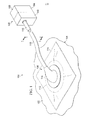
- FIG. 1 is a schematic perspective view of an illustrative embodiment of a system for treating a tissue site with reduced pressure
- FIG. 2 is a schematic, cross-sectional view of an illustrative embodiment of a multi-lumen conduit of the system shown in FIG. 1 taken along line 2 - 2 ;
- FIG. 3 is a schematic, cross-sectional view of one illustrative embodiment of a reduced-pressure interface having a cutting element for use as part of a system for treating a tissue site with reduced pressure;
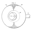
- FIG. 4 is a schematic, bottom view of the reduced-pressure interface of FIG. 3 ;
- FIG. 5A is a schematic, cross-sectional view of the reduced-pressure interface of FIG. 3 under reduced pressure prior to the cutting element perforating a sealing member;
- FIG. 5B is another schematic, cross-sectional view of the reduced-pressure interface of FIG. 3 under reduced pressure after the cutting member has perforated the sealing member;
- FIG. 5C is another schematic, cross-sectional view of the reduced-pressure interface of FIG. 3 under reduced pressure after the cutting member has perforated the sealing member and the cutting element has been removed;
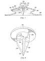
- FIG. 6 is a schematic, top perspective view of another illustrative embodiment of a reduced-pressure interface having a cutting element for use as part of a system for treating a tissue site with reduced pressure;
- FIG. 7 is a schematic, cross-sectional view of the reduced-pressure interface of FIG. 6 ;
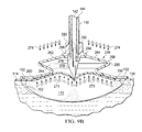
- FIG. 8 is a schematic, bottom perspective view of a portion of the reduced-pressure interface of FIG. 6 ;
- FIG. 9A is a schematic, cross-sectional view of the reduced-pressure interface of FIGS. 6-8 being applied and prior to reduced pressure being supplied;
- FIG. 9B is a schematic, cross-sectional view of the reduced-pressure interface of FIGS. 6-8 under reduced pressure prior to the cutting element perforating a sealing member;
- FIG. 9C is a schematic, cross-sectional view of the reduced-pressure interface of FIGS. 6-8 under reduced pressure after the cutting member has perforated the sealing member and the cutting element has been removed;
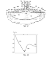
- FIG. 10 is a schematic diagram of a representative pressure set-up pattern.
- reduced pressure generally refers to a pressure less than the ambient pressure at a tissue site that is being subjected to treatment. In most cases, this reduced pressure will be less than the atmospheric pressure at which the patient is located. Alternatively, the reduced pressure may be less than a hydrostatic pressure associated with tissue at the tissue site. Unless otherwise indicated, values of pressure stated herein are gauge pressures. References to increases in reduced pressure typically refer to a decrease in absolute pressure, and decreases in reduced pressure typically refer to an increase in absolute pressure.
- the system 100 includes a reduced-pressure dressing 106 for disposing proximate the tissue site 102 .
- the system 100 also includes a reduced-pressure treatment unit 108 fluidly connected to the reduced-pressure dressing 106 through a reduced-pressure delivery conduit 110 for applying reduced pressure to the tissue site 102 .
- the reduced-pressure dressing 106 may further include a distribution manifold 112 , a sealing member 114 , and a reduced-pressure interface 116 .
- the reduced-pressure interface 116 includes a cutting element 118 adapted to form an aperture 120 (see FIG.
- Including the cutting element 118 on the reduced-pressure interface 116 provides a number of potential benefits.
- the benefits may include ease of application and the reduction of error when forming the aperture 120 .
- errors in (1) positioning the aperture 120 on the dressing, (2) sizing of the aperture 120 , and (3) the formation of the aperture 120 may be reduced.
- Incorrectly forming the aperture 120 may leave portions of the sealing member 114 in a position that can block the aperture 120 when reduced pressure is applied.
- the system 100 may be used with various different types of tissue sites 102 .
- the tissue site 102 may be a wound 122 or wound cavity. As shown in at least FIGS. 5A-5C , the tissue site 102 or wound 122 , may be through an epidermis 124 and into a subcutaneous tissue 126 or any other tissue.
- the tissue site 102 may be the bodily tissue of any human, animal, or other organism, including bone tissue, adipose tissue, muscle tissue, dermal tissue, vascular tissue, connective tissue, cartilage, tendons, ligaments, body cavity or any other tissue. Treatment of the tissue site 102 may include removal of fluids, e.g., exudate or ascites.
- the distribution manifold 112 is proximate the tissue site 102 and has a first side 128 and a second, tissue-facing side 130 .
- the term “distribution manifold” as used herein generally refers to a substance or structure that is provided to assist in applying reduced pressure to, delivering fluids to, or removing fluids from the tissue site 102 .
- the distribution manifold 112 typically includes a plurality of flow channels or pathways that distribute fluids provided to and removed from the tissue site 102 around the distribution manifold 112 . In one illustrative embodiment, the flow channels or pathways are interconnected to improve distribution of fluids provided or removed from the tissue site 102 .
- the distribution manifold 112 may be a biocompatible material that is capable of being placed in contact with the tissue site 102 and distributing reduced pressure to the tissue site 102 .
- Examples of the distribution manifold 112 may include, without limitation, devices that have structural elements arranged to form flow channels, such as, for example, cellular foam, open-cell foam, porous tissue collections, liquids, gels, and foams that include, or cure to include, flow channels.
- the distribution manifold 112 may be porous and may be made from foam, gauze, felted mat, or any other material suited to a particular biological application.
- the distribution manifold 112 is a porous foam and includes a plurality of interconnected cells or pores that act as flow channels.
- the porous foam may be a polyurethane, open-cell, reticulated foam such as GranuFoam® material manufactured by Kinetic Concepts, Incorporated of San Antonio, Tex.
- the distribution manifold 112 may also be used to distribute fluids such as medications, antibacterials, growth factors, and various solutions to the tissue site 102 .
- Other layers may be included in or on the distribution manifold 112 , such as absorptive materials, wicking materials, hydrophobic materials, and hydrophilic materials.
- the distribution manifold 112 may be constructed from bioresorbable materials that do not have to be removed from a patient's body following use of the system 100 .
- Suitable bioresorbable materials may include, without limitation, a polymeric blend of polylactic acid (PLA) and polyglycolic acid (PGA).
- the polymeric blend may also include without limitation polycarbonates, polyfumarates, and capralactones.
- the distribution manifold 112 may further serve as a scaffold for new cell-growth, or a scaffold material may be used in conjunction with the distribution manifold 112 to promote cell-growth.
- a scaffold is a substance or structure used to enhance or promote the growth of cells or formation of tissue, such as a three-dimensional porous structure that provides a template for cell growth.
- Illustrative examples of scaffold materials include calcium phosphate, collagen, PLA/PGA, coral hydroxy apatites, carbonates, or processed allograft materials.
- the distribution manifold 112 may be covered by the sealing member 114 , which may also be referred to as a drape.
- the sealing member 114 forms a sealed space 132 over the tissue site 102 .
- the sealing member 114 has a first side 134 , and a second, tissue-facing side 136 .
- the sealing member 114 may be any material that provides a fluid seal. “Fluid seal,” or “seal,” means a seal adequate to maintain reduced pressure at a desired site given the particular reduced-pressure source or subsystem involved.
- the sealing member 114 may, for example, be an impermeable or semi-permeable, elastomeric material. “Elastomeric” means having the properties of an elastomer.
- Elastomer generally refers to a polymeric material that has rubber-like properties. More specifically, most elastomers have ultimate elongations greater than 100% and a significant amount of resilience. The resilience of a material refers to the material's ability to recover from an elastic deformation. Elastomers that are relatively less resilient may also be used as these elastomers are more likely to tear when faced with the cutting element 118 .
- elastomers may include, but are not limited to, natural rubbers, polyisoprene, styrene butadiene rubber, chloroprene rubber, polybutadiene, nitrile rubber, butyl rubber, ethylene propylene rubber, ethylene propylene diene monomer, chlorosulfonated polyethylene, polysulfide rubber, polyurethane (PU), EVA film, co-polyester, and silicones.
- Additional, specific examples of dressing sealing member materials include a silicone drape, 3M Tegaderm® drape, polyurethane (PU) drape such as one available from Avery Dennison Corporation of Pasadena, Calif.
- An additional, specific non-limiting example of a dressing sealing member material includes a 30 ⁇ m matt polyurethane film such as the InspireTM 2317 manufactured by ExopackTM Advanced Coatings of Matthews, N.C..
- An attachment device 134 may be used to hold the sealing member 114 against a portion of the patient's intact epidermis 124 or another layer, such as a gasket or additional sealing member.
- the attachment device 134 may take numerous forms.
- the attachment device 134 may be a medically acceptable adhesive, such as a pressure-sensitive adhesive, that extends about a periphery or all of the sealing member 114 .
- the attachment device 134 may also be a sealing ring or other device.
- the attachment device 134 is disposed on the second, tissue-facing side of the sealing member 114 . Before use, the attachment device 134 may be covered by a release liner (not shown).
- the reduced-pressure interface 116 may be positioned adjacent to or coupled to the sealing member 114 to provide fluid access to the distribution manifold 112 .
- Another attachment device 138 similar to the attachment device 134 may be used to hold the reduced-pressure interface 116 against the sealing member 114 .
- the reduced-pressure delivery conduit 110 fluidly couples the reduced-pressure treatment unit 108 and the reduced-pressure interface 116 .
- the reduced-pressure interface 116 allows the reduced pressure to be delivered to the tissue site 102 .
- the reduced pressure will typically be between ⁇ 5 mm Hg ( ⁇ 667 Pa) and ⁇ 500 mm Hg ( ⁇ 66.7 kPa) and more typically between ⁇ 75 mm Hg ( ⁇ 9.9 kPa) and ⁇ 300 mm Hg ( ⁇ 39.9 kPa).
- the pressure may be ⁇ 12, ⁇ 12.5, ⁇ 13, ⁇ 14, ⁇ 14.5, ⁇ 15, ⁇ 15.5, ⁇ 16, ⁇ 16.5, ⁇ 17, ⁇ 17.5, ⁇ 18, ⁇ 18.5, ⁇ 19, ⁇ 19.5, ⁇ 20, ⁇ 20.5, ⁇ 21, ⁇ 21.5, ⁇ 22, ⁇ 22.5, ⁇ 23, ⁇ 23.5, ⁇ 24, ⁇ 24.5, ⁇ 25, ⁇ 25.5, ⁇ 26, ⁇ 26.5 kPa or another pressure.
- the reduced-pressure delivery conduit 110 is a multi-lumen conduit. It should be understood, however, that the reduced-pressure delivery conduit 110 may be in many forms and may comprise a single lumen.
- the reduced-pressure delivery conduit 110 may include a primary lumen 142 and at least one sensing lumen 144 .
- the primary lumen 142 is a central lumen 146 and the at least one sensing lumen 144 is one or more peripheral lumens 148 .
- the primary lumen 142 and the at least one sensing lumen 144 are adapted to maintain fluid isolation between the primary lumen 142 and the at least one sensing lumen 144 as the reduced-pressure delivery conduit 110 transports fluids from the reduced-pressure interface 116 to the reduced-pressure treatment unit 108 .
- Liquids or exudates communicated from the distribution manifold 112 through the primary lumen 142 are removed from the reduced-pressure delivery conduit 110 and retained within a liquid-collection chamber (not explicitly shown) in fluid communication with the reduced-pressure treatment unit 108 .
- the at least one sensing lumen 144 fluidly communicates reduced pressure representative of the tissue site 102 to an instrumentation unit 150 .
- the reduced-pressure treatment unit 108 may include a liquid-collection chamber, or a collection canister, and the instrumentation unit 150 in fluid communication with a reduced-pressure source 140 .
- the instrumentation unit 150 may include a microprocessor 154 adapted to process pressure signals received by the reduced-pressure delivery conduit 110 , monitor the pressure signals, and issue alerts according to a pre-determined pressure configuration.
- the pre-determined pressure configuration may include a pressure set-up pattern of sustained decrease, increase, and relative stability within an application time period as will be described in more detail with respect to FIG. 10 below.
- the reduced-pressure source 140 is an electrically-driven vacuum pump. In another implementation, the reduced-pressure source 140 may instead be a manually-actuated or manually-charged pump that does not require electrical power. The reduced-pressure source 140 instead may be any other type of reduced pressure pump, or alternatively a wall suction port such as those available in hospitals and other medical facilities.
- the reduced-pressure source 140 may be housed within or used in conjunction with the reduced-pressure treatment unit 108 , which may also include the instrumentation unit 150 .
- the instrumentation unit 150 may include sensors, processing units, alarm indicators, memory, databases, software, display units, and user interfaces that further facilitate the application of reduced pressure treatment to the tissue site 102 .
- pressure-detection sensors located in the instrumentation unit 150 may be disposed at or near the reduced-pressure source 140 .
- the pressure-detection sensors may receive pressure data, or a pressure signal, from the reduced-pressure interface 116 via the at least one sensing lumen 144 that is dedicated to delivering reduced pressure data to the pressure-detection sensors.
- the pressure signal or data may be representative of a pressure at a distal end 186 of the at least one sensing lumen 144 .
- the pressure-detection sensors may communicate with a processing unit that monitors and controls the reduced pressure that is delivered by the reduced-pressure source 140 .
- the pressure-detection sensors communicate with the processing unit to monitor whether the pressure signal follows the pressure set-up pattern. In the event the pressure signal does not follow the pressure set-up pattern within an application time period that may be predetermined, the instrumentation unit 150 provides an indication to a caregiver. The indication may be in the form of a visual or audible alert or alarm. Other indications may be used.
- the pressure-detection sensors may communicate with the processing unit to monitor whether the pressure signal does follow the pressure set-up pattern within an application time period. In the event the pressure signal does follow the pressure set-up pattern, the instrumentation unit 150 provides an indication to the caregiver. The indication that the pressure set-up pattern has been followed may be different than the indication that the pressure set-up pattern has not been followed.
- the reduced-pressure interface 116 includes a housing 158 , a conduit port 168 coupled to the housing 158 , and the attachment device 152 for coupling the reduced-pressure interface 116 to the sealing member 114 .
- the reduced-pressure interface 116 further includes the cutting element 118 .
- the housing 158 may have a flange portion 160 and a cavity wall portion 162 .
- the cavity wall portion 162 forms a cavity 164 having a tissue-facing cavity opening 166 .
- the conduit port 168 is coupled to or formed as part of the cavity wall portion 162 of the housing 158 .
- the conduit port 168 includes a conduit aperture 170 whereby the conduit port 168 is adapted to receive the reduced-pressure delivery conduit 110 .
- the attachment device 138 may be coupled to a tissue-facing side 172 of the flange portion 160 for coupling the housing 158 to the first side 134 of the sealing member 114 .
- the housing 158 is made of a semi-rigid material that is capable of collapsing under a force such as a driving force 174 .
- the reduced-pressure interface 116 may be made from a plasticized polyvinyl chloride (PVC), polyurethane, cyclic olefin copolymer elastomer, thermoplastic elastomer, poly acrylic, silicone polymer, and polyether block amide copolymer.
- PVC polyvinyl chloride
- polyurethane polyurethane
- cyclic olefin copolymer elastomer cyclic olefin copolymer elastomer
- thermoplastic elastomer poly acrylic, silicone polymer, and polyether block amide copolymer.
- the cutting element 118 may be at least temporarily coupled to the housing 158 proximate to the tissue-facing cavity opening 166 .
- the cutting element 118 is adapted to form the aperture 120 in the sealing member 114 when the cutting element 118 is driven into the sealing member 114 with the driving force 174 .
- the driving force 174 may also cause the cutting element 118 to penetrate or cut a portion of the distribution manifold 112 .
- the driving force 174 may be manually applied to an exterior 184 of the reduced-pressure interface 116 causing the housing 158 to collapse and thereby driving or pushing the cutting element 118 into the sealing member 114 .
- the driving force 174 is applied by applying reduced pressure to the cavity 164 such that a cavity pressure (P c ) in the cavity 164 is less than a threshold pressure (P t ).
- a cavity pressure (P c ) in the cavity 164 is less than a threshold pressure (P t ).
- P t threshold pressure
- the threshold pressure (P t ) is at least in part dependent on the type and thickness of the material used for the housing 158 .
- a tensile force may be applied to the sealing member 114 causing the sealing member 114 to pull into the cavity 164 . This movement further assists with the cutting element 118 moving into the sealing member 114 .
- the cutting element 118 includes a base member 176 and a stylus member 178 coupled to the base member 176 .
- the stylus member 178 has a leading edge 180 and is configured to perforate the sealing member 114 to form the aperture 120 in the sealing member 114 .
- the leading edge 180 is serrated.
- the leading edge 180 is serrated or configured to perforate the sealing member 114 orthogonally.
- the sealing member 114 may be perforated orthogonally to inhibit the cut sealing member 114 from blocking the reduced-pressure delivery conduit 110 during reduced pressure therapy.
- the base member 176 may be sized and configured to form an interference fit with the tissue-facing cavity opening 166 , whereby the cutting element 118 is releasably coupled to the housing 158 .
- the cutting element 118 may be removed prior to use if not desired or after perforating the sealing member 114 .
- the cutting element 118 may have a piercing length (L p ) extending the length (L) of the stylus member 178 .
- the length (L) of the stylus member 178 extends from the base member 176 to a tip 182 of the stylus member 178 .
- the piercing length (L p ) is less than 3 centimeters.
- the piercing length (L p ) is less than 2 centimeters.
- the distribution manifold 112 may have a thickness greater than T when subject to reduced pressure such that the piercing length (L p ) of the cutting element 118 is less than the thickness T, i.e., L p ⁇ T.
- One benefit of the piercing length (L p ) being less than the thickness, T, of the distribution manifold 112 under reduced pressure is that the cutting element 118 cannot completely cut through the distribution manifold 112 and reach the tissue site 102 .
- the cutting element 118 may be only temporarily coupled to the housing 158 .
- the cutting element 118 may be removed by a care giver.
- the cutting element 118 may be formed from a liquid soluble material such as a water soluble material adapted to allow the cutting element 118 to dissolve.
- the water soluble material may include at least one of the following: Polyvinyl alcohol (PVOH), polyvinyl pyrrolidone, hydroxyl and carboxyl modified cellulose, hydroxyl and carboxyl modified acrylics, starch, sugars (sucrose, glucose, fructose), weak acids (tartaric, citric, malic), salts (sodium chloride, sodium carbonate, sodium bicarbonate), polyethylene oxide (PEO), polyethylene glycol (PEG).
- PVOH Polyvinyl alcohol
- polyvinyl pyrrolidone polyvinyl pyrrolidone
- hydroxyl and carboxyl modified cellulose hydroxyl and carboxyl modified acrylics
- starch sugars (sucrose, glucose, fructose), weak acids (tartaric, citric, malic), salts (sodium chloride, sodium carbonate, sodium bicarbonate), polyethylene oxide (PEO), polyethylene glycol (PEG).
- PEO polyethylene oxide
- PEG polyethylene glyco
- liquids removed from the tissue site 102 cause the cutting element 118 to substantially dissolve.
- the cutting element 118 may dissolve within 2 minutes, 5 minutes, 10 minutes, or another time period.
- a liquid, e.g., saline solution may also be introduced through the reduced-pressure delivery conduit 110 or otherwise to dissolve the cutting element 118 .
- reduced pressure applied through the reduced-pressure interface 116 creates sufficient reduced pressure in the cavity 164 to pull a portion of the distribution manifold 112 into the cavity 164 such that the distribution manifold 112 abuts a distal end of the reduced-pressure delivery conduit 110 to include a distal aperture 186 of the at least one sensing lumen 144 . Allowing the distribution manifold 112 to completely abut the distal end of the reduced-pressure delivery conduit 110 may help ensure fluid isolation between each of the lumens in the reduced-pressure delivery conduit 110 .
- the distribution manifold 112 may provide a barrier between the primary lumen 142 and the at least one sensing lumen 144 .
- having the reduced-pressure delivery conduit 110 in direct contact with the distribution manifold 112 may help ensure that there is a constant low velocity liquid flow into the reduced-pressure delivery conduit 110 which may minimize the instance of aerosolized particles being deposited around the at least one sensing lumen 144 and may also provide a filter to liquids entering the at least one sensing lumen 144 .
- a caregiver may treat the tissue site 102 on the patient 104 with a method that includes disposing the distribution manifold 112 proximate to the tissue site 102 .
- the distribution manifold 112 and a portion of intact epidermis 124 of the patient 104 is covered with the sealing member 114 to form the sealed space 132 in which the distribution manifold 112 is disposed.
- the reduced-pressure interface 116 is coupled to the sealing member 114 .
- the reduced-pressure delivery conduit 110 is fluidly coupled on one end to the reduced-pressure source 140 and on the opposing end to the reduced-pressure interface 116 .
- the driving force 174 is then applied to the reduced-pressure interface 116 with sufficient strength to cause the cutting element 118 to perforate (e.g., pierce, tear, cut or otherwise create the aperture 120 ) the sealing member 114 .
- the reduced-pressure interface 116 includes the housing 158 having the wall portion, wherein the wall portion forms the cavity 164 having the tissue-facing cavity opening 166 .
- the housing 158 is formed of a semi-rigid material that collapses when under reduced pressure less than the threshold pressure (P t ).
- the conduit port 168 is coupled to the wall portion of the housing 158 .
- the conduit port 168 is further coupled to the reduced-pressure delivery conduit 110 . Reduced pressure is supplied to the reduced-pressure interface 116 through the reduced-pressure delivery conduit 110 and the conduit port 168 .
- the wall portion collapses under the driving force 174 and impacts the cutting element 118 , driving a portion of the cutting element 118 through the sealing member 114 to perforate the sealing member 114 .
- liquid in response to the sealing member 114 being perforated, liquid is removed from the tissue site 102 through the reduced-pressure delivery conduit 110 .
- Liquid is removed from the tissue site 102 by virtue of reduced pressure.
- the liquid causes the cutting element 118 to dissolve.
- reduced pressure within the cavity 164 of the reduced-pressure interface 116 causes a portion of the distribution manifold 112 to be pulled into the cavity 164 and abut the reduced-pressure delivery conduit 110 . Fluid may then be directly transferred from the distribution manifold 112 to the reduced-pressure delivery conduit 110 without going through an additional medium or open space.
- the reduced-pressure interface 216 is analogous in many respects to the reduced-pressure interface 116 of FIGS. 3-5C .
- the reduced-pressure interface 216 includes a housing 258 and a cutting element 218 .
- the housing 258 may have a flange portion 260 and a cavity wall portion 262 .
- the flange portion 260 may be coupled to the sealing member 114 by the attachment device 138 .
- the cavity wall portion 262 is collapsible under reduced pressure.
- the cavity wall portion 262 may include a bellows configuration 290 for permitting the cavity wall portion 262 to collapse when a cavity 164 pressure (P c ) inside a cavity 264 is less than a threshold pressure (P t ) on an absolute pressure side.
- the cutting element 218 may include a conduit adapter 292 , an adapter flange 294 , a tube extension 296 , a base member 276 , and a stylus member 278 .
- the conduit adapter 292 is configured to receive the reduced-pressure delivery conduit 110 to provide fluid communication between the reduced-pressure treatment unit 108 and the tissue site 102 .
- the conduit adapter 292 includes a protrusion 293 for engaging the primary lumen 142 of the reduced-pressure delivery conduit 110 .
- the protrusion 293 may be sized and configured to extend into the primary lumen 142 and to form an interference fit. The protrusion 293 may help maintain fluid isolation between the primary lumen 142 and the at least one sensing lumen 144 .
- the adapter flange 294 is positioned on an exterior 284 of the cavity wall portion 262 .
- the tube extension 296 is connected to the adapter flange 294 and is sized and configured to mate with a conduit aperture 298 .
- the tube extension 296 is further configured to extend through the conduit aperture 298 .
- the conduit adapter 292 , the adapter flange 294 , and the tube extension 296 may be formed from materials to include plasticized polyvinyl chloride (PVC), polyurethane, cyclic olefin copolymer elastomer, thermoplastic elastomer, poly acrylic, silicone polymer, and polyether block amide copolymer.
- PVC plasticized polyvinyl chloride
- polyurethane polyurethane
- cyclic olefin copolymer elastomer cyclic olefin copolymer elastomer
- thermoplastic elastomer poly acrylic, silicone polymer, and polyether block
- the base member 276 may be at least temporarily coupled to the tube extension 296 .
- the stylus member 278 is directly coupled to the base member 276 and may include a first blade 297 and a second blade 299 configured to make orthogonal cuts in the sealing member 114 when the housing 258 is compressed with a driving force thereby impacting the cutting element 218 .
- the stylus member 278 is thus driven into the sealing member 114 .
- the driving force may be manually applied to the exterior 284 of the reduced-pressure interface 216 causing the housing 258 to collapse and thereby driving or pushing the cutting element 218 into the sealing member 114 .
- the driving force is applied by applying reduced pressure to the cavity 264 such that the cavity pressure (P c ) in the cavity 264 is less than a threshold pressure (P t ).
- P t a threshold pressure
- the cavity wall portion 262 collapses and impacts the cutting element 218 .
- the threshold pressure (P t ) is at least in part dependent on the type and thickness of material used for the housing 258 .
- a tensile force 273 may be applied to the sealing member 114 causing the sealing member 114 to be pulled into the cavity 264 . This movement helps the cutting element 218 to be driven into the sealing member 114 .
- the base member 276 may be only temporarily coupled to the housing 258 .
- the base member 276 and the stylus member 278 may be formed from a liquid soluble material such as a water soluble material adapted to allow the cutting element 118 to dissolve.
- the water soluble material may include at least one of the following: Polyvinyl alcohol (PVOH), polyvinyl pyrrolidone, hydroxyl and carboxyl modified cellulose, hydroxyl and carboxyl modified acrylics, starch, sugars (sucrose, glucose, fructose), weak acids (tartaric, citric, malic), salts (sodium chloride, sodium carbonate, sodium bicarbonate), polyethylene oxide (PEO), polyethylene glycol (PEG).
- the base member 276 and the stylus member 278 may dissolve as liquids are removed from the tissue site 102 .
- Reduced pressure is applied to the reduced-pressure interface 216 typically causing liquids to be removed from the tissue site 102 .
- liquids removed from the tissue site 102 may cause the base member 276 and the stylus member 278 to substantially dissolve.
- the base member 276 and the stylus member 278 may dissolve within 2 minutes, 5 minutes, 8 minutes, 10 minutes, or another time period.
- the base member 276 and the stylus member 278 are removed by the reduced-pressure delivery conduit 110 with the liquids from the tissue site 102 . While the base member 276 and the stylus member 278 may be dissolvable, it is worth noting that the conduit adapter 292 , the adapter flange 294 , and the tube extension 296 do not dissolve.
- reduced pressure applied through the reduced-pressure interface 216 creates sufficient reduced pressure in the cavity 264 to pull a portion of the distribution manifold 112 into the cavity 264 and the primary lumen 142 of the reduced-pressure delivery conduit 110 .
- the distribution manifold 112 abuts the distal end of the reduced-pressure delivery conduit 110 including the distal aperture 186 of the at least one sensing lumen 144 . Allowing the distribution manifold 112 to completely abut the distal end of the reduced-pressure delivery conduit 110 may help ensure fluid isolation between each of the lumens in the reduced-pressure delivery conduit 110 .
- the pressure set-up pattern may be a pre-determined pressure configuration.
- Pressure-detection sensors may communicate with a processing unit to monitor whether pressure signals received from a reduced-pressure interface follow or is consistent with the pressure set-up pattern.
- the pressure set-up pattern may be representative of whether a cutting element of the reduced-pressure interface has pierced a sealing member.
- the pressure set-up pattern may represent four main events. First, a period of sustained pressure decrease (reduced pressure increase) may be indicative of a period of time prior to the cutting element piercing the sealing member. This segment is shown generally by reference numeral 302 .
Landscapes
- Health & Medical Sciences (AREA)
- Heart & Thoracic Surgery (AREA)
- Life Sciences & Earth Sciences (AREA)
- Veterinary Medicine (AREA)
- Animal Behavior & Ethology (AREA)
- Engineering & Computer Science (AREA)
- Biomedical Technology (AREA)
- Public Health (AREA)
- General Health & Medical Sciences (AREA)
- Vascular Medicine (AREA)
- Hematology (AREA)
- Anesthesiology (AREA)
- Pulmonology (AREA)
- Biophysics (AREA)
- Media Introduction/Drainage Providing Device (AREA)
- Materials For Medical Uses (AREA)
- Surgical Instruments (AREA)
- External Artificial Organs (AREA)
Abstract
Description
- This application is a continuation of U.S. application Ser. No. 13/554,620, filed Jul. 20, 2012, which claims the benefit, under 35 USC §119(e), of the filing of U.S. Provisional Patent Application Ser. No. 61/511,840, entitled “Systems and Methods for Treating a Tissue Site with Reduced Pressure Involving a Reduced-Pressure Interface having a Cutting Element,” filed Jul. 26, 2011, and U.S. Provisional Patent Application Ser. No. 61/511,827, entitled “Systems and Methods for Treating a Tissue Site with Reduced Pressure Involving a Reduced-Pressure Interface having a Multi-Lumen Conduit for Contacting a Manifold,” filed Jul. 26, 2011, which is incorporated herein by reference for all purposes.
- The present disclosure relates generally to medical treatment systems and, more particularly, but not by way of limitation, to systems, methods, and apparatuses for treating a tissue site with reduced pressure involving a reduced-pressure interface having a cutting element.
- Clinical studies and practice have shown that providing a reduced pressure in proximity to a tissue site augments and accelerates the growth of new tissue at the tissue site. The applications of this phenomenon are numerous, but application of reduced pressure has been particularly successful in treating wounds. This treatment (frequently referred to in the medical community as “negative pressure wound therapy,” “reduced pressure therapy,” or “vacuum therapy”) provides a number of benefits, which may include faster healing and increased formulation of granulation tissue. Typically, reduced pressure is applied to tissue through a manifold device. The porous pad contains cells or pores distributes reduced pressure to the tissue and channel fluids that are drawn from the tissue.
- According to an illustrative embodiment a reduced-pressure interface for providing reduced pressure through a sealing member to a distribution manifold includes a housing having a flange portion and a cavity wall portion such that the cavity wall portion forms a cavity having a tissue-facing cavity opening. A conduit port is coupled to the cavity wall and has a conduit aperture, such that the conduit port is adapted to receive a reduced-pressure delivery conduit. An attachment device is coupled to a tissue-facing side of the flange portion of the housing such that the attachment device couples the housing to the sealing member. Additionally, a cutting element is at least temporarily coupled to the housing proximate to the tissue-facing cavity opening such that the cutting element is adapted to form an aperture in the sealing member when the cutting element is driven into the sealing member with a driving force.
- According to another illustrative embodiment a system for treating a tissue site on a patient with reduced pressure includes a distribution manifold for placing proximate to the tissue site, a sealing member for covering the distribution manifold and a portion of intact epidermis of the patient to form a sealed space, a reduced-pressure interface for providing reduced pressure through the sealing member to the distribution manifold, a reduced-pressure source, and a reduced-pressure delivery conduit for fluidly coupling the reduced-pressure source to the reduced-pressure interface. The reduced-pressure interface includes a housing having a flange portion and a cavity wall portion such that the cavity wall portion forms a cavity having a tissue-facing cavity opening, a conduit port coupled to the cavity wall and having a conduit aperture such that the conduit port is adapted to receive the reduced-pressure delivery conduit, an attachment device coupled to a tissue-facing side of the flange portion of the housing such that the attachment device couples the housing to the sealing member, and a cutting element at least temporarily coupled to the housing proximate to the tissue-facing cavity opening. The cutting element is adapted to form an aperture in the sealing member when the cutting element is driven into the sealing member with a driving force.
- According to another illustrative embodiment a method for treating a tissue site on a patient with reduced pressure includes disposing a distribution manifold proximate to the tissue site and covering the distribution manifold and a portion of intact epidermis of the patient with a sealing member to form a sealed space in which the distribution manifold is disposed. The sealing member has a first side and a second, tissue-facing side. The method further includes providing a reduced-pressure source, coupling a reduced-pressure interface proximate to the first side of the sealing member, and fluidly coupling a reduced-pressure delivery conduit between the reduced pressure source and the reduced-pressure interface. The reduced-pressure interface includes a housing having a wall portion such that the wall portion forms a cavity having a tissue-facing cavity opening, a conduit port coupled to the cavity wall for receiving the reduced-pressure delivery conduit, an attachment device for coupling the reduced-pressure interface to the sealing member, and a cutting element at least temporarily coupled to the housing proximate to the tissue-facing cavity opening such that the cutting element is adapted to perforate the sealing member when the cutting element is driven into the sealing member with a driving force. The method also includes applying a driving force to the reduced-pressure interface of sufficient strength to cause the cutting element to perforate the sealing member.
- According to yet another illustrative embodiment, an interface for providing reduced pressure through a drape to a manifold includes a housing having a flange portion and a cavity wall portion. The cavity wall portion forms a cavity and a cavity wall aperture is formed within the cavity wall portion for receiving a tube. The interface further includes a coupler positioned on a tissue-facing side of the flange portion of the housing for attaching the housing to the drape and a protrusion coupled to the housing proximate to the flange portion. The protrusion extends beyond the tissue-facing side of the flange portion of the housing and is configured to form an aperture in the drape when the protrusion is driven into the drape with the reduced pressure.
- According to another illustrative embodiment, a system for treating a wound with reduced pressure includes a manifold for positioning adjacent the wound, a drape for covering the manifold and a portion of intact epidermis of the patient to form a sealed space, a reduced-pressure interface for providing reduced pressure through the drape to the manifold, a reduced-pressure source, and a conduit for fluidly coupling the reduced-pressure source to the reduced-pressure interface. The reduced-pressure interface includes a housing having a flange portion and a cavity wall portion. The cavity wall portion forms a cavity and a cavity wall aperture is formed within the cavity wall portion for receiving a tube. The reduced-pressure interface further includes a coupler positioned on a tissue-facing side of the flange portion of the housing for attaching the housing to the drape and a protrusion coupled to the housing proximate to the flange portion. The protrusion extends beyond the tissue-facing side of the flange portion of the housing and is configured to form an aperture in the drape when the protrusion is driven into the drape with the reduced pressure.
- In another illustrative embodiment, a method for treating a wound on a patient with reduced pressure includes disposing a manifold proximate to the wound, covering the manifold and a portion of intact epidermis of the patient with a drape to form a sealed space in which the manifold is disposed. The drape has a first side and a second, tissue-facing side. The method further includes providing a reduced-pressure source, coupling a reduced-pressure interface proximate to the first side of the drape, and fluidly coupling a tube between the reduced-pressure source and the reduced-pressure interface. The reduced-pressure interface includes a housing having a flange portion and a cavity wall portion. The cavity wall portion forms a cavity and a cavity wall aperture is formed within the cavity wall portion for receiving a tube. The reduced-pressure interface further includes a coupler positioned on a tissue-facing side of the flange portion of the housing for attaching the housing to the drape and a protrusion coupled to the housing proximate to the flange portion. The protrusion extends beyond the tissue-facing side of the flange portion of the housing and is configured to form an aperture in the drape when the protrusion is driven into the drape with a driving force. The method further includes applying the driving force to the reduced-pressure interface of sufficient strength to cause the protrusion to perforate the drape.
- Other features and advantages of the illustrative embodiments will become apparent with reference to the drawings and detailed description that follow.
-
FIG. 1 is a schematic perspective view of an illustrative embodiment of a system for treating a tissue site with reduced pressure; -
FIG. 2 is a schematic, cross-sectional view of an illustrative embodiment of a multi-lumen conduit of the system shown inFIG. 1 taken along line 2-2; -
FIG. 3 is a schematic, cross-sectional view of one illustrative embodiment of a reduced-pressure interface having a cutting element for use as part of a system for treating a tissue site with reduced pressure; -
FIG. 4 is a schematic, bottom view of the reduced-pressure interface ofFIG. 3 ; -
FIG. 5A is a schematic, cross-sectional view of the reduced-pressure interface ofFIG. 3 under reduced pressure prior to the cutting element perforating a sealing member; -
FIG. 5B is another schematic, cross-sectional view of the reduced-pressure interface ofFIG. 3 under reduced pressure after the cutting member has perforated the sealing member; -
FIG. 5C is another schematic, cross-sectional view of the reduced-pressure interface ofFIG. 3 under reduced pressure after the cutting member has perforated the sealing member and the cutting element has been removed; -
FIG. 6 is a schematic, top perspective view of another illustrative embodiment of a reduced-pressure interface having a cutting element for use as part of a system for treating a tissue site with reduced pressure; -
FIG. 7 is a schematic, cross-sectional view of the reduced-pressure interface ofFIG. 6 ; -
FIG. 8 is a schematic, bottom perspective view of a portion of the reduced-pressure interface ofFIG. 6 ; -
FIG. 9A is a schematic, cross-sectional view of the reduced-pressure interface ofFIGS. 6-8 being applied and prior to reduced pressure being supplied; -
FIG. 9B is a schematic, cross-sectional view of the reduced-pressure interface ofFIGS. 6-8 under reduced pressure prior to the cutting element perforating a sealing member; -
FIG. 9C is a schematic, cross-sectional view of the reduced-pressure interface ofFIGS. 6-8 under reduced pressure after the cutting member has perforated the sealing member and the cutting element has been removed; and -
FIG. 10 is a schematic diagram of a representative pressure set-up pattern. - In the following detailed description of the illustrative embodiments, reference is made to the accompanying drawings that form a part hereof. These embodiments are described in sufficient detail to enable those skilled in the art to practice the invention, and it is understood that other embodiments may be utilized and that logical structural, mechanical, electrical, and chemical changes may be made without departing from the spirit or scope of the invention. To avoid detail not necessary to enable those skilled in the art to practice the embodiments described herein, the description may omit certain information known to those skilled in the art. The following detailed description is, therefore, not to be taken in a limiting sense, and the scope of the illustrative embodiments are defined only by the appended claims. Unless otherwise indicated, as used herein, “or” does not require mutual exclusivity.
- The term “reduced pressure” as used herein generally refers to a pressure less than the ambient pressure at a tissue site that is being subjected to treatment. In most cases, this reduced pressure will be less than the atmospheric pressure at which the patient is located. Alternatively, the reduced pressure may be less than a hydrostatic pressure associated with tissue at the tissue site. Unless otherwise indicated, values of pressure stated herein are gauge pressures. References to increases in reduced pressure typically refer to a decrease in absolute pressure, and decreases in reduced pressure typically refer to an increase in absolute pressure.
- Referring now to the drawings and initially to
FIGS. 1-5C , and specifically toFIGS. 1 and 3 , asystem 100 for treating atissue site 102 on apatient 104 with reduced pressure is presented. Thesystem 100 includes a reduced-pressure dressing 106 for disposing proximate thetissue site 102. Thesystem 100 also includes a reduced-pressure treatment unit 108 fluidly connected to the reduced-pressure dressing 106 through a reduced-pressure delivery conduit 110 for applying reduced pressure to thetissue site 102. The reduced-pressure dressing 106 may further include adistribution manifold 112, a sealingmember 114, and a reduced-pressure interface 116. The reduced-pressure interface 116 includes acutting element 118 adapted to form an aperture 120 (seeFIG. 5B ) in the sealingmember 114. Including the cuttingelement 118 on the reduced-pressure interface 116 provides a number of potential benefits. The benefits may include ease of application and the reduction of error when forming theaperture 120. In a non-limiting example, errors in (1) positioning theaperture 120 on the dressing, (2) sizing of theaperture 120, and (3) the formation of theaperture 120 may be reduced. Incorrectly forming theaperture 120 may leave portions of the sealingmember 114 in a position that can block theaperture 120 when reduced pressure is applied. - The
system 100 may be used with various different types oftissue sites 102. Thetissue site 102 may be awound 122 or wound cavity. As shown in at leastFIGS. 5A-5C , thetissue site 102 or wound 122, may be through anepidermis 124 and into asubcutaneous tissue 126 or any other tissue. Thetissue site 102 may be the bodily tissue of any human, animal, or other organism, including bone tissue, adipose tissue, muscle tissue, dermal tissue, vascular tissue, connective tissue, cartilage, tendons, ligaments, body cavity or any other tissue. Treatment of thetissue site 102 may include removal of fluids, e.g., exudate or ascites. - Referring still to
FIGS. 1-5C , thedistribution manifold 112 is proximate thetissue site 102 and has afirst side 128 and a second, tissue-facingside 130. The term “distribution manifold” as used herein generally refers to a substance or structure that is provided to assist in applying reduced pressure to, delivering fluids to, or removing fluids from thetissue site 102. Thedistribution manifold 112 typically includes a plurality of flow channels or pathways that distribute fluids provided to and removed from thetissue site 102 around thedistribution manifold 112. In one illustrative embodiment, the flow channels or pathways are interconnected to improve distribution of fluids provided or removed from thetissue site 102. Thedistribution manifold 112 may be a biocompatible material that is capable of being placed in contact with thetissue site 102 and distributing reduced pressure to thetissue site 102. Examples of thedistribution manifold 112 may include, without limitation, devices that have structural elements arranged to form flow channels, such as, for example, cellular foam, open-cell foam, porous tissue collections, liquids, gels, and foams that include, or cure to include, flow channels. Thedistribution manifold 112 may be porous and may be made from foam, gauze, felted mat, or any other material suited to a particular biological application. In one embodiment, thedistribution manifold 112 is a porous foam and includes a plurality of interconnected cells or pores that act as flow channels. The porous foam may be a polyurethane, open-cell, reticulated foam such as GranuFoam® material manufactured by Kinetic Concepts, Incorporated of San Antonio, Tex. In some situations, thedistribution manifold 112 may also be used to distribute fluids such as medications, antibacterials, growth factors, and various solutions to thetissue site 102. Other layers may be included in or on thedistribution manifold 112, such as absorptive materials, wicking materials, hydrophobic materials, and hydrophilic materials. - In one illustrative the
distribution manifold 112 may be constructed from bioresorbable materials that do not have to be removed from a patient's body following use of thesystem 100. Suitable bioresorbable materials may include, without limitation, a polymeric blend of polylactic acid (PLA) and polyglycolic acid (PGA). The polymeric blend may also include without limitation polycarbonates, polyfumarates, and capralactones. Thedistribution manifold 112 may further serve as a scaffold for new cell-growth, or a scaffold material may be used in conjunction with thedistribution manifold 112 to promote cell-growth. A scaffold is a substance or structure used to enhance or promote the growth of cells or formation of tissue, such as a three-dimensional porous structure that provides a template for cell growth. Illustrative examples of scaffold materials include calcium phosphate, collagen, PLA/PGA, coral hydroxy apatites, carbonates, or processed allograft materials. - The
distribution manifold 112 may be covered by the sealingmember 114, which may also be referred to as a drape. The sealingmember 114 forms a sealedspace 132 over thetissue site 102. The sealingmember 114 has afirst side 134, and a second, tissue-facing side 136. The sealingmember 114 may be any material that provides a fluid seal. “Fluid seal,” or “seal,” means a seal adequate to maintain reduced pressure at a desired site given the particular reduced-pressure source or subsystem involved. The sealingmember 114 may, for example, be an impermeable or semi-permeable, elastomeric material. “Elastomeric” means having the properties of an elastomer. Elastomer generally refers to a polymeric material that has rubber-like properties. More specifically, most elastomers have ultimate elongations greater than 100% and a significant amount of resilience. The resilience of a material refers to the material's ability to recover from an elastic deformation. Elastomers that are relatively less resilient may also be used as these elastomers are more likely to tear when faced with the cuttingelement 118. Examples of elastomers may include, but are not limited to, natural rubbers, polyisoprene, styrene butadiene rubber, chloroprene rubber, polybutadiene, nitrile rubber, butyl rubber, ethylene propylene rubber, ethylene propylene diene monomer, chlorosulfonated polyethylene, polysulfide rubber, polyurethane (PU), EVA film, co-polyester, and silicones. Additional, specific examples of dressing sealing member materials include a silicone drape, 3M Tegaderm® drape, polyurethane (PU) drape such as one available from Avery Dennison Corporation of Pasadena, Calif. An additional, specific non-limiting example of a dressing sealing member material includes a 30 μm matt polyurethane film such as the Inspire™ 2317 manufactured by Exopack™ Advanced Coatings of Matthews, N.C.. - An
attachment device 134 may be used to hold the sealingmember 114 against a portion of the patient'sintact epidermis 124 or another layer, such as a gasket or additional sealing member. Theattachment device 134 may take numerous forms. For example, theattachment device 134 may be a medically acceptable adhesive, such as a pressure-sensitive adhesive, that extends about a periphery or all of the sealingmember 114. Theattachment device 134 may also be a sealing ring or other device. Theattachment device 134 is disposed on the second, tissue-facing side of the sealingmember 114. Before use, theattachment device 134 may be covered by a release liner (not shown). - The reduced-
pressure interface 116 may be positioned adjacent to or coupled to the sealingmember 114 to provide fluid access to thedistribution manifold 112. Anotherattachment device 138 similar to theattachment device 134 may be used to hold the reduced-pressure interface 116 against the sealingmember 114. The reduced-pressure delivery conduit 110 fluidly couples the reduced-pressure treatment unit 108 and the reduced-pressure interface 116. The reduced-pressure interface 116 allows the reduced pressure to be delivered to thetissue site 102. While the amount and nature of reduced pressure applied to a tissue site will typically vary according to the application, the reduced pressure will typically be between −5 mm Hg (−667 Pa) and −500 mm Hg (−66.7 kPa) and more typically between −75 mm Hg (−9.9 kPa) and −300 mm Hg (−39.9 kPa). For example, and not by way of limitation, the pressure may be −12, −12.5, −13, −14, −14.5, −15, −15.5, −16, −16.5, −17, −17.5, −18, −18.5, −19, −19.5, −20, −20.5, −21, −21.5, −22, −22.5, −23, −23.5, −24, −24.5, −25, −25.5, −26, −26.5 kPa or another pressure. - As shown, the reduced-
pressure delivery conduit 110 is a multi-lumen conduit. It should be understood, however, that the reduced-pressure delivery conduit 110 may be in many forms and may comprise a single lumen. The reduced-pressure delivery conduit 110 may include aprimary lumen 142 and at least onesensing lumen 144. In one illustrative embodiment theprimary lumen 142 is acentral lumen 146 and the at least onesensing lumen 144 is one or moreperipheral lumens 148. Theprimary lumen 142 and the at least onesensing lumen 144 are adapted to maintain fluid isolation between theprimary lumen 142 and the at least onesensing lumen 144 as the reduced-pressure delivery conduit 110 transports fluids from the reduced-pressure interface 116 to the reduced-pressure treatment unit 108. Liquids or exudates communicated from thedistribution manifold 112 through theprimary lumen 142 are removed from the reduced-pressure delivery conduit 110 and retained within a liquid-collection chamber (not explicitly shown) in fluid communication with the reduced-pressure treatment unit 108. The at least onesensing lumen 144 fluidly communicates reduced pressure representative of thetissue site 102 to aninstrumentation unit 150. - The reduced-
pressure treatment unit 108 may include a liquid-collection chamber, or a collection canister, and theinstrumentation unit 150 in fluid communication with a reduced-pressure source 140. Theinstrumentation unit 150 may include amicroprocessor 154 adapted to process pressure signals received by the reduced-pressure delivery conduit 110, monitor the pressure signals, and issue alerts according to a pre-determined pressure configuration. The pre-determined pressure configuration may include a pressure set-up pattern of sustained decrease, increase, and relative stability within an application time period as will be described in more detail with respect toFIG. 10 below. - In an illustrative embodiment, the reduced-
pressure source 140 is an electrically-driven vacuum pump. In another implementation, the reduced-pressure source 140 may instead be a manually-actuated or manually-charged pump that does not require electrical power. The reduced-pressure source 140 instead may be any other type of reduced pressure pump, or alternatively a wall suction port such as those available in hospitals and other medical facilities. The reduced-pressure source 140 may be housed within or used in conjunction with the reduced-pressure treatment unit 108, which may also include theinstrumentation unit 150. Theinstrumentation unit 150 may include sensors, processing units, alarm indicators, memory, databases, software, display units, and user interfaces that further facilitate the application of reduced pressure treatment to thetissue site 102. - In one example, pressure-detection sensors (not shown) located in the
instrumentation unit 150 may be disposed at or near the reduced-pressure source 140. The pressure-detection sensors may receive pressure data, or a pressure signal, from the reduced-pressure interface 116 via the at least onesensing lumen 144 that is dedicated to delivering reduced pressure data to the pressure-detection sensors. The pressure signal or data may be representative of a pressure at adistal end 186 of the at least onesensing lumen 144. The pressure-detection sensors may communicate with a processing unit that monitors and controls the reduced pressure that is delivered by the reduced-pressure source 140. In one embodiment, the pressure-detection sensors communicate with the processing unit to monitor whether the pressure signal follows the pressure set-up pattern. In the event the pressure signal does not follow the pressure set-up pattern within an application time period that may be predetermined, theinstrumentation unit 150 provides an indication to a caregiver. The indication may be in the form of a visual or audible alert or alarm. Other indications may be used. In an alternative, but not mutually exclusive, embodiment, the pressure-detection sensors may communicate with the processing unit to monitor whether the pressure signal does follow the pressure set-up pattern within an application time period. In the event the pressure signal does follow the pressure set-up pattern, theinstrumentation unit 150 provides an indication to the caregiver. The indication that the pressure set-up pattern has been followed may be different than the indication that the pressure set-up pattern has not been followed. - Referring now primarily to
FIGS. 3-5C , an illustrative embodiment of the reduced-pressure interface 116 is presented in more detail. The reduced-pressure interface 116 includes ahousing 158, aconduit port 168 coupled to thehousing 158, and theattachment device 152 for coupling the reduced-pressure interface 116 to the sealingmember 114. The reduced-pressure interface 116 further includes the cuttingelement 118. - The
housing 158 may have aflange portion 160 and acavity wall portion 162. Thecavity wall portion 162 forms acavity 164 having a tissue-facingcavity opening 166. Theconduit port 168 is coupled to or formed as part of thecavity wall portion 162 of thehousing 158. Theconduit port 168 includes aconduit aperture 170 whereby theconduit port 168 is adapted to receive the reduced-pressure delivery conduit 110. Theattachment device 138 may be coupled to a tissue-facingside 172 of theflange portion 160 for coupling thehousing 158 to thefirst side 134 of the sealingmember 114. Thehousing 158 is made of a semi-rigid material that is capable of collapsing under a force such as a drivingforce 174. In a non-limiting example, the reduced-pressure interface 116, and thus thehousing 158, may be made from a plasticized polyvinyl chloride (PVC), polyurethane, cyclic olefin copolymer elastomer, thermoplastic elastomer, poly acrylic, silicone polymer, and polyether block amide copolymer. - The cutting
element 118 may be at least temporarily coupled to thehousing 158 proximate to the tissue-facingcavity opening 166. The cuttingelement 118 is adapted to form theaperture 120 in the sealingmember 114 when the cuttingelement 118 is driven into the sealingmember 114 with the drivingforce 174. The drivingforce 174 may also cause thecutting element 118 to penetrate or cut a portion of thedistribution manifold 112. The drivingforce 174 may be manually applied to anexterior 184 of the reduced-pressure interface 116 causing thehousing 158 to collapse and thereby driving or pushing the cuttingelement 118 into the sealingmember 114. In another embodiment, the drivingforce 174 is applied by applying reduced pressure to thecavity 164 such that a cavity pressure (Pc) in thecavity 164 is less than a threshold pressure (Pt). When the cavity pressure (Pc) is less than the threshold pressure (Pt), thecavity wall portion 162 collapses and with continued reduced pressure impacts thecutting element 118 thereby driving a portion of the cuttingelement 118 through the sealingmember 114. The threshold pressure (Pt) is at least in part dependent on the type and thickness of the material used for thehousing 158. In the event reduced pressure is applied to thecavity 164, a tensile force may be applied to the sealingmember 114 causing the sealingmember 114 to pull into thecavity 164. This movement further assists with the cuttingelement 118 moving into the sealingmember 114. - In one embodiment, the cutting
element 118 includes abase member 176 and astylus member 178 coupled to thebase member 176. Thestylus member 178 has aleading edge 180 and is configured to perforate the sealingmember 114 to form theaperture 120 in the sealingmember 114. In one embodiment, theleading edge 180 is serrated. In another embodiment, theleading edge 180 is serrated or configured to perforate the sealingmember 114 orthogonally. The sealingmember 114 may be perforated orthogonally to inhibit thecut sealing member 114 from blocking the reduced-pressure delivery conduit 110 during reduced pressure therapy. Thebase member 176 may be sized and configured to form an interference fit with the tissue-facingcavity opening 166, whereby the cuttingelement 118 is releasably coupled to thehousing 158. Thus, in one embodiment, the cuttingelement 118 may be removed prior to use if not desired or after perforating the sealingmember 114. - The cutting
element 118 may have a piercing length (Lp) extending the length (L) of thestylus member 178. The length (L) of thestylus member 178 extends from thebase member 176 to atip 182 of thestylus member 178. In one embodiment, the piercing length (Lp) is less than 3 centimeters. In another embodiment, the piercing length (Lp) is less than 2 centimeters. Thedistribution manifold 112 may have a thickness greater than T when subject to reduced pressure such that the piercing length (Lp) of the cuttingelement 118 is less than the thickness T, i.e., Lp<T. One benefit of the piercing length (Lp) being less than the thickness, T, of thedistribution manifold 112 under reduced pressure is that the cuttingelement 118 cannot completely cut through thedistribution manifold 112 and reach thetissue site 102. - As previously mentioned, the cutting
element 118 may be only temporarily coupled to thehousing 158. In one embodiment, the cuttingelement 118 may be removed by a care giver. In another embodiment, the cuttingelement 118 may be formed from a liquid soluble material such as a water soluble material adapted to allow thecutting element 118 to dissolve. For example, the water soluble material may include at least one of the following: Polyvinyl alcohol (PVOH), polyvinyl pyrrolidone, hydroxyl and carboxyl modified cellulose, hydroxyl and carboxyl modified acrylics, starch, sugars (sucrose, glucose, fructose), weak acids (tartaric, citric, malic), salts (sodium chloride, sodium carbonate, sodium bicarbonate), polyethylene oxide (PEO), polyethylene glycol (PEG). The cuttingelement 118 may dissolve as liquids are removed from thetissue site 102. Reduced pressure is applied to the reduced-pressure interface 116 after perforating the sealingmember 114 typically causing liquids to be removed from thetissue site 102. After a sufficient amount of time, liquids removed from thetissue site 102 cause thecutting element 118 to substantially dissolve. The cuttingelement 118 may dissolve within 2 minutes, 5 minutes, 10 minutes, or another time period. As thecutting element 118 is dissolved it is removed by the reduced-pressure delivery conduit 110 with liquids from thetissue site 102. A liquid, e.g., saline solution, may also be introduced through the reduced-pressure delivery conduit 110 or otherwise to dissolve thecutting element 118. - As shown in
FIG. 5C , once the cuttingelement 118 has substantially dissolved, reduced pressure applied through the reduced-pressure interface 116 creates sufficient reduced pressure in thecavity 164 to pull a portion of thedistribution manifold 112 into thecavity 164 such that thedistribution manifold 112 abuts a distal end of the reduced-pressure delivery conduit 110 to include adistal aperture 186 of the at least onesensing lumen 144. Allowing thedistribution manifold 112 to completely abut the distal end of the reduced-pressure delivery conduit 110 may help ensure fluid isolation between each of the lumens in the reduced-pressure delivery conduit 110. Thedistribution manifold 112 may provide a barrier between theprimary lumen 142 and the at least onesensing lumen 144. Additionally, having the reduced-pressure delivery conduit 110 in direct contact with thedistribution manifold 112 may help ensure that there is a constant low velocity liquid flow into the reduced-pressure delivery conduit 110 which may minimize the instance of aerosolized particles being deposited around the at least onesensing lumen 144 and may also provide a filter to liquids entering the at least onesensing lumen 144. - In operation, a caregiver may treat the
tissue site 102 on thepatient 104 with a method that includes disposing thedistribution manifold 112 proximate to thetissue site 102. Thedistribution manifold 112 and a portion ofintact epidermis 124 of thepatient 104 is covered with the sealingmember 114 to form the sealedspace 132 in which thedistribution manifold 112 is disposed. The reduced-pressure interface 116 is coupled to the sealingmember 114. The reduced-pressure delivery conduit 110 is fluidly coupled on one end to the reduced-pressure source 140 and on the opposing end to the reduced-pressure interface 116. The drivingforce 174 is then applied to the reduced-pressure interface 116 with sufficient strength to cause thecutting element 118 to perforate (e.g., pierce, tear, cut or otherwise create the aperture 120) the sealingmember 114. - In one embodiment, the reduced-
pressure interface 116 includes thehousing 158 having the wall portion, wherein the wall portion forms thecavity 164 having the tissue-facingcavity opening 166. Thehousing 158 is formed of a semi-rigid material that collapses when under reduced pressure less than the threshold pressure (Pt). Theconduit port 168 is coupled to the wall portion of thehousing 158. Theconduit port 168 is further coupled to the reduced-pressure delivery conduit 110. Reduced pressure is supplied to the reduced-pressure interface 116 through the reduced-pressure delivery conduit 110 and theconduit port 168. When reduced pressure levels in thecavity 164 are less than the threshold pressure (Pt), the wall portion collapses under the drivingforce 174 and impacts thecutting element 118, driving a portion of the cuttingelement 118 through the sealingmember 114 to perforate the sealingmember 114. - In one embodiment, in response to the sealing
member 114 being perforated, liquid is removed from thetissue site 102 through the reduced-pressure delivery conduit 110. Liquid is removed from thetissue site 102 by virtue of reduced pressure. The liquid causes thecutting element 118 to dissolve. Once the cuttingelement 118 has substantially dissolved, reduced pressure within thecavity 164 of the reduced-pressure interface 116 causes a portion of thedistribution manifold 112 to be pulled into thecavity 164 and abut the reduced-pressure delivery conduit 110. Fluid may then be directly transferred from thedistribution manifold 112 to the reduced-pressure delivery conduit 110 without going through an additional medium or open space. - Referring now primarily to
FIGS. 6-9C , another illustrative embodiment of a reduced-pressure interface 216 is presented. The reduced-pressure interface 216 is analogous in many respects to the reduced-pressure interface 116 ofFIGS. 3-5C . The reduced-pressure interface 216 includes ahousing 258 and a cutting element 218. Thehousing 258 may have aflange portion 260 and acavity wall portion 262. Theflange portion 260 may be coupled to the sealingmember 114 by theattachment device 138. Thecavity wall portion 262 is collapsible under reduced pressure. Thecavity wall portion 262 may include abellows configuration 290 for permitting thecavity wall portion 262 to collapse when acavity 164 pressure (Pc) inside acavity 264 is less than a threshold pressure (Pt) on an absolute pressure side. - The cutting element 218 may include a
conduit adapter 292, anadapter flange 294, atube extension 296, abase member 276, and astylus member 278. Theconduit adapter 292 is configured to receive the reduced-pressure delivery conduit 110 to provide fluid communication between the reduced-pressure treatment unit 108 and thetissue site 102. Theconduit adapter 292 includes aprotrusion 293 for engaging theprimary lumen 142 of the reduced-pressure delivery conduit 110. Theprotrusion 293 may be sized and configured to extend into theprimary lumen 142 and to form an interference fit. Theprotrusion 293 may help maintain fluid isolation between theprimary lumen 142 and the at least onesensing lumen 144. Theadapter flange 294 is positioned on anexterior 284 of thecavity wall portion 262. Thetube extension 296 is connected to theadapter flange 294 and is sized and configured to mate with aconduit aperture 298. Thetube extension 296 is further configured to extend through theconduit aperture 298. In a specific, non-limiting example, theconduit adapter 292, theadapter flange 294, and thetube extension 296 may be formed from materials to include plasticized polyvinyl chloride (PVC), polyurethane, cyclic olefin copolymer elastomer, thermoplastic elastomer, poly acrylic, silicone polymer, and polyether block amide copolymer. - The
base member 276 may be at least temporarily coupled to thetube extension 296. Thestylus member 278 is directly coupled to thebase member 276 and may include afirst blade 297 and asecond blade 299 configured to make orthogonal cuts in the sealingmember 114 when thehousing 258 is compressed with a driving force thereby impacting the cutting element 218. Thestylus member 278 is thus driven into the sealingmember 114. The driving force may be manually applied to theexterior 284 of the reduced-pressure interface 216 causing thehousing 258 to collapse and thereby driving or pushing the cutting element 218 into the sealingmember 114. In another embodiment, the driving force is applied by applying reduced pressure to thecavity 264 such that the cavity pressure (Pc) in thecavity 264 is less than a threshold pressure (Pt). When the cavity pressure (Pc) in thecavity 264 is less than the threshold pressure (Pt), thecavity wall portion 262 collapses and impacts the cutting element 218. With continued reduced pressure, a portion of the cutting element 218 is driven through the sealingmember 114. The threshold pressure (Pt) is at least in part dependent on the type and thickness of material used for thehousing 258. In the event reduced pressure is applied to thecavity 264, atensile force 273 may be applied to the sealingmember 114 causing the sealingmember 114 to be pulled into thecavity 264. This movement helps the cutting element 218 to be driven into the sealingmember 114. - As previously mentioned, the
base member 276 may be only temporarily coupled to thehousing 258. In one embodiment, thebase member 276 and thestylus member 278 may be formed from a liquid soluble material such as a water soluble material adapted to allow thecutting element 118 to dissolve. The water soluble material may include at least one of the following: Polyvinyl alcohol (PVOH), polyvinyl pyrrolidone, hydroxyl and carboxyl modified cellulose, hydroxyl and carboxyl modified acrylics, starch, sugars (sucrose, glucose, fructose), weak acids (tartaric, citric, malic), salts (sodium chloride, sodium carbonate, sodium bicarbonate), polyethylene oxide (PEO), polyethylene glycol (PEG). Thebase member 276 and thestylus member 278 may dissolve as liquids are removed from thetissue site 102. Reduced pressure is applied to the reduced-pressure interface 216 typically causing liquids to be removed from thetissue site 102. After a sufficient amount of time, liquids removed from thetissue site 102 may cause thebase member 276 and thestylus member 278 to substantially dissolve. Thebase member 276 and thestylus member 278 may dissolve within 2 minutes, 5 minutes, 8 minutes, 10 minutes, or another time period. As thebase member 276 and thestylus member 278 are dissolved, thebase member 276 and thestylus member 278 are removed by the reduced-pressure delivery conduit 110 with the liquids from thetissue site 102. While thebase member 276 and thestylus member 278 may be dissolvable, it is worth noting that theconduit adapter 292, theadapter flange 294, and thetube extension 296 do not dissolve. - Once the
base member 276 and thestylus member 278 have substantially dissolved, reduced pressure applied through the reduced-pressure interface 216 creates sufficient reduced pressure in thecavity 264 to pull a portion of thedistribution manifold 112 into thecavity 264 and theprimary lumen 142 of the reduced-pressure delivery conduit 110. Thedistribution manifold 112 abuts the distal end of the reduced-pressure delivery conduit 110 including thedistal aperture 186 of the at least onesensing lumen 144. Allowing thedistribution manifold 112 to completely abut the distal end of the reduced-pressure delivery conduit 110 may help ensure fluid isolation between each of the lumens in the reduced-pressure delivery conduit 110. - Referring now primarily to
FIG. 10 , a schematic diagram of a pressure set-up pattern is presented. The pressure set-up pattern may be a pre-determined pressure configuration. Pressure-detection sensors may communicate with a processing unit to monitor whether pressure signals received from a reduced-pressure interface follow or is consistent with the pressure set-up pattern. The pressure set-up pattern may be representative of whether a cutting element of the reduced-pressure interface has pierced a sealing member. The pressure set-up pattern may represent four main events. First, a period of sustained pressure decrease (reduced pressure increase) may be indicative of a period of time prior to the cutting element piercing the sealing member. This segment is shown generally byreference numeral 302. During this period of time, pressure is decreasing in a cavity of the reduced-pressure interface causing the cavity to collapse. Second, a threshold pressure (Pt) is reached and pressure increases (reduced pressure decreases) indicating that the cutting element has pierced the sealing member. This segment is generally shown bynumeral 304. The pressure should increase as the pressure in the sealed space beneath the sealing member stabilizes. And third, a period of pressure stability is reached as shown generally asreference numeral 306. - Although the present invention and its advantages have been disclosed in the context of certain illustrative, non-limiting embodiments, it should be understood that various changes, substitutions, permutations, and alterations can be made without departing from the scope of the invention as defined by the appended claims. It will be appreciated that any feature that is described in connection to any one embodiment may also be applicable to any other embodiment.
- It will be understood that the benefits and advantages described above may relate to one embodiment or may relate to several embodiments. It will further be understood that reference to ‘an’ item refers to one or more of those items.
- The steps of the methods described herein may be carried out in any suitable order, or simultaneously where appropriate.
- Where appropriate, aspects of any of the examples described above may be combined with aspects of any of the other examples described to form further examples having comparable or different properties and addressing the same or different problems.
- It will be understood that the above description of preferred embodiments is given by way of example only and that various modifications may be made by those skilled in the art. The above specification, examples and data provide a complete description of the structure and use of exemplary embodiments of the invention. Although various embodiments of the invention have been described above with a certain degree of particularity, or with reference to one or more individual embodiments, those skilled in the art could make numerous alterations to the disclosed embodiments without departing from the scope of the claims.
Claims (46)
Priority Applications (3)
| Application Number | Priority Date | Filing Date | Title |
|---|---|---|---|
| US14/276,853 US9878077B2 (en) | 2011-07-26 | 2014-05-13 | Systems and methods for treating a tissue site with reduced pressure involving a reduced-pressure interface having a cutting element |
| US15/842,274 US10576189B2 (en) | 2011-07-26 | 2017-12-14 | Systems and methods for treating a tissue site with reduced pressure involving a reduced-pressure interface having a cutting element |
| US16/750,224 US20200155736A1 (en) | 2011-07-26 | 2020-01-23 | Systems and methods for treating a tissue site with reduced pressure involving a reduced-pressure interface having a cutting element |
Applications Claiming Priority (4)
| Application Number | Priority Date | Filing Date | Title |
|---|---|---|---|
| US201161511840P | 2011-07-26 | 2011-07-26 | |
| US201161511827P | 2011-07-26 | 2011-07-26 | |
| US13/554,620 US8758328B2 (en) | 2011-07-26 | 2012-07-20 | Systems and methods for treating a tissue site with reduced pressure involving a reduced-pressure interface having a cutting element |
| US14/276,853 US9878077B2 (en) | 2011-07-26 | 2014-05-13 | Systems and methods for treating a tissue site with reduced pressure involving a reduced-pressure interface having a cutting element |
Related Parent Applications (1)
| Application Number | Title | Priority Date | Filing Date |
|---|---|---|---|
| US13/554,620 Continuation US8758328B2 (en) | 2011-07-26 | 2012-07-20 | Systems and methods for treating a tissue site with reduced pressure involving a reduced-pressure interface having a cutting element |
Related Child Applications (1)
| Application Number | Title | Priority Date | Filing Date |
|---|---|---|---|
| US15/842,274 Continuation US10576189B2 (en) | 2011-07-26 | 2017-12-14 | Systems and methods for treating a tissue site with reduced pressure involving a reduced-pressure interface having a cutting element |
Publications (2)
| Publication Number | Publication Date |
|---|---|
| US20140336601A1 true US20140336601A1 (en) | 2014-11-13 |
| US9878077B2 US9878077B2 (en) | 2018-01-30 |
Family
ID=46584414
Family Applications (8)
| Application Number | Title | Priority Date | Filing Date |
|---|---|---|---|
| US13/554,542 Active 2032-07-25 US9023012B2 (en) | 2011-07-26 | 2012-07-20 | Systems and methods for treating a tissue site with reduced pressure involving a reduced-pressure interface having a multi-lumen conduit for contacting a manifold |
| US13/554,620 Active 2032-07-25 US8758328B2 (en) | 2011-07-26 | 2012-07-20 | Systems and methods for treating a tissue site with reduced pressure involving a reduced-pressure interface having a cutting element |
| US14/276,853 Active 2033-01-24 US9878077B2 (en) | 2011-07-26 | 2014-05-13 | Systems and methods for treating a tissue site with reduced pressure involving a reduced-pressure interface having a cutting element |
| US14/678,698 Active 2033-01-25 US9750857B2 (en) | 2011-07-26 | 2015-04-03 | Systems and methods for treating a tissue site with reduced pressure involving a reduced-pressure interface having a multi-lumen conduit for contacting a manifold |
| US15/657,989 Active 2033-03-29 US10660993B2 (en) | 2011-07-26 | 2017-07-24 | Systems and methods for treating a tissue site with reduced pressure involving a reduced-pressure interface having a multi-lumen conduit for contacting a manifold |
| US15/842,274 Active 2033-02-02 US10576189B2 (en) | 2011-07-26 | 2017-12-14 | Systems and methods for treating a tissue site with reduced pressure involving a reduced-pressure interface having a cutting element |
| US16/750,224 Abandoned US20200155736A1 (en) | 2011-07-26 | 2020-01-23 | Systems and methods for treating a tissue site with reduced pressure involving a reduced-pressure interface having a cutting element |
| US16/789,671 Abandoned US20200179581A1 (en) | 2011-07-26 | 2020-02-13 | Systems And Methods For Treating A Tissue Site With Reduced Pressure Involving A Reduced-Pressure Interface Having A Multi-Lumen Conduit For Contacting A Manifold |
Family Applications Before (2)
| Application Number | Title | Priority Date | Filing Date |
|---|---|---|---|
| US13/554,542 Active 2032-07-25 US9023012B2 (en) | 2011-07-26 | 2012-07-20 | Systems and methods for treating a tissue site with reduced pressure involving a reduced-pressure interface having a multi-lumen conduit for contacting a manifold |
| US13/554,620 Active 2032-07-25 US8758328B2 (en) | 2011-07-26 | 2012-07-20 | Systems and methods for treating a tissue site with reduced pressure involving a reduced-pressure interface having a cutting element |
Family Applications After (5)
| Application Number | Title | Priority Date | Filing Date |
|---|---|---|---|
| US14/678,698 Active 2033-01-25 US9750857B2 (en) | 2011-07-26 | 2015-04-03 | Systems and methods for treating a tissue site with reduced pressure involving a reduced-pressure interface having a multi-lumen conduit for contacting a manifold |
| US15/657,989 Active 2033-03-29 US10660993B2 (en) | 2011-07-26 | 2017-07-24 | Systems and methods for treating a tissue site with reduced pressure involving a reduced-pressure interface having a multi-lumen conduit for contacting a manifold |
| US15/842,274 Active 2033-02-02 US10576189B2 (en) | 2011-07-26 | 2017-12-14 | Systems and methods for treating a tissue site with reduced pressure involving a reduced-pressure interface having a cutting element |
| US16/750,224 Abandoned US20200155736A1 (en) | 2011-07-26 | 2020-01-23 | Systems and methods for treating a tissue site with reduced pressure involving a reduced-pressure interface having a cutting element |
| US16/789,671 Abandoned US20200179581A1 (en) | 2011-07-26 | 2020-02-13 | Systems And Methods For Treating A Tissue Site With Reduced Pressure Involving A Reduced-Pressure Interface Having A Multi-Lumen Conduit For Contacting A Manifold |
Country Status (7)
| Country | Link |
|---|---|
| US (8) | US9023012B2 (en) |
| EP (5) | EP2736549B1 (en) |
| JP (3) | JP6193855B2 (en) |
| CN (2) | CN103781501B (en) |
| AU (2) | AU2012287137B2 (en) |
| CA (2) | CA2843317C (en) |
| WO (2) | WO2013016239A1 (en) |
Families Citing this family (109)
| Publication number | Priority date | Publication date | Assignee | Title |
|---|---|---|---|---|
| US11298453B2 (en) | 2003-10-28 | 2022-04-12 | Smith & Nephew Plc | Apparatus and method for wound cleansing with actives |
| US10058642B2 (en) | 2004-04-05 | 2018-08-28 | Bluesky Medical Group Incorporated | Reduced pressure treatment system |
| US7909805B2 (en) | 2004-04-05 | 2011-03-22 | Bluesky Medical Group Incorporated | Flexible reduced pressure treatment appliance |
| GB0508531D0 (en) | 2005-04-27 | 2005-06-01 | Smith & Nephew | Sai with ultrasound |
| GB0723872D0 (en) | 2007-12-06 | 2008-01-16 | Smith & Nephew | Apparatus for topical negative pressure therapy |
| GB2455962A (en) | 2007-12-24 | 2009-07-01 | Ethicon Inc | Reinforced adhesive backing sheet, for plaster |
| EP2249761B1 (en) | 2008-03-05 | 2017-04-19 | KCI Licensing, Inc. | Dressing for applying reduced pressure to and collecting and storing fluid from a tissue site |
| US8298200B2 (en) | 2009-06-01 | 2012-10-30 | Tyco Healthcare Group Lp | System for providing continual drainage in negative pressure wound therapy |
| GB0808376D0 (en) | 2008-05-08 | 2008-06-18 | Bristol Myers Squibb Co | Wound dressing |
| JP5502083B2 (en) | 2008-08-08 | 2014-05-28 | スミス アンド ネフュー インコーポレイテッド | Continuous fiber wound dressing |
| GB0817796D0 (en) | 2008-09-29 | 2008-11-05 | Convatec Inc | wound dressing |
| GB0902816D0 (en) | 2009-02-19 | 2009-04-08 | Smith & Nephew | Fluid communication path |
| US20100324516A1 (en) | 2009-06-18 | 2010-12-23 | Tyco Healthcare Group Lp | Apparatus for Vacuum Bridging and/or Exudate Collection |
| US8814842B2 (en) | 2010-03-16 | 2014-08-26 | Kci Licensing, Inc. | Delivery-and-fluid-storage bridges for use with reduced-pressure systems |
| AU2011316599B2 (en) | 2010-10-12 | 2018-09-20 | Smith & Nephew, Inc. | Medical device |
| GB201020236D0 (en) | 2010-11-30 | 2011-01-12 | Convatec Technologies Inc | A composition for detecting biofilms on viable tissues |
| CN103347561B (en) | 2010-12-08 | 2016-09-07 | 康沃特克科技公司 | For assessing the integrated system of wound exudate |
| DK2648795T3 (en) | 2010-12-08 | 2023-03-27 | Convatec Technologies Inc | System for removing exudates from a wound site |
| CN103347562B (en) | 2010-12-08 | 2016-08-10 | 康沃特克科技公司 | Wound exudate system accessory |
| BR112013018320A2 (en) | 2010-12-22 | 2018-09-11 | Smith & Nephew, Inc. | negative pressure wound therapy apparatus and methods |
| GB2488749A (en) | 2011-01-31 | 2012-09-12 | Systagenix Wound Man Ip Co Bv | Laminated silicone coated wound dressing |
| GB201106491D0 (en) | 2011-04-15 | 2011-06-01 | Systagenix Wound Man Ip Co Bv | Patterened silicone coating |
| AU2012333210B2 (en) | 2011-06-24 | 2017-01-19 | Solventum Intellectual Properties Company | Reduced-pressure dressings employing tissue-fixation elements |
| EP2736549B1 (en) * | 2011-07-26 | 2018-05-16 | KCI Licensing, Inc. | Systems for treating a tissue site with reduced pressure involving a reduced-pressure interface having a cutting element |
| GB201115182D0 (en) | 2011-09-02 | 2011-10-19 | Trio Healthcare Ltd | Skin contact material |
| GB2497406A (en) | 2011-11-29 | 2013-06-12 | Webtec Converting Llc | Dressing with a perforated binder layer |
| GB201120693D0 (en) | 2011-12-01 | 2012-01-11 | Convatec Technologies Inc | Wound dressing for use in vacuum therapy |
| US10940047B2 (en) | 2011-12-16 | 2021-03-09 | Kci Licensing, Inc. | Sealing systems and methods employing a hybrid switchable drape |
| JP6320930B2 (en) | 2011-12-16 | 2018-05-09 | ケーシーアイ ライセンシング インコーポレイテッド | Peelable medical drape |
| EP2825220B2 (en) | 2012-03-12 | 2021-03-03 | Smith & Nephew PLC | Reduced pressure apparatus and methods |
| US9907703B2 (en) | 2012-05-23 | 2018-03-06 | Smith & Nephew Plc | Apparatuses and methods for negative pressure wound therapy |
| ES2625709T3 (en) | 2012-08-01 | 2017-07-20 | Smith & Nephew Plc. | Wound dressing |
| US10076449B2 (en) | 2012-08-01 | 2018-09-18 | Smith & Nephew Plc | Wound dressing and method of treatment |
| CN111991092A (en) | 2012-11-16 | 2020-11-27 | 凯希特许有限公司 | Medical drape having patterned adhesive layer and method of making same |
| GB201222770D0 (en) | 2012-12-18 | 2013-01-30 | Systagenix Wound Man Ip Co Bv | Wound dressing with adhesive margin |
| KR20150099776A (en) | 2012-12-20 | 2015-09-01 | 컨바텍 테크놀러지스 인크 | Processing of chemically modified cellulosic fibres |
| USD738487S1 (en) * | 2013-01-28 | 2015-09-08 | Molnlycke Health Care Ab | Suction device for negative pressure therapy |
| US9662429B2 (en) | 2013-03-14 | 2017-05-30 | Kci Licensing, Inc. | Negative pressure therapy with dynamic profile capability |
| US9737649B2 (en) | 2013-03-14 | 2017-08-22 | Smith & Nephew, Inc. | Systems and methods for applying reduced pressure therapy |
| EP2968012B1 (en) | 2013-03-14 | 2017-04-26 | KCI Licensing, Inc. | Absorbent dressing with hybrid drape |
| US10328188B2 (en) | 2013-03-14 | 2019-06-25 | Smith & Nephew, Inc. | Systems and methods for applying reduced pressure therapy |
| EP2994176B1 (en) | 2013-05-10 | 2020-07-08 | Smith & Nephew plc | Fluidic connector for irrigation and aspiration of wounds |
| AU2014306876B2 (en) | 2013-08-13 | 2019-05-02 | Smith & Nephew, Inc. | Systems and methods for applying reduced pressure therapy |
| WO2015030963A1 (en) | 2013-08-26 | 2015-03-05 | Kci Licensing, Inc. | Dressing interface with moisture controlling feature and sealing function |
| EP3470030B1 (en) | 2013-10-28 | 2024-06-26 | Solventum Intellectual Properties Company | Hybrid sealing tape |
| WO2015065615A1 (en) * | 2013-10-30 | 2015-05-07 | Kci Licensing, Inc. | Absorbent conduit and system |
| US10398814B2 (en) | 2013-10-30 | 2019-09-03 | Kci Licensing, Inc. | Condensate absorbing and dissipating system |
| AU2014342903B2 (en) | 2013-10-30 | 2018-09-20 | Solventum Intellectual Properties Company | Dressing with differentially sized perforations |
| US9956120B2 (en) | 2013-10-30 | 2018-05-01 | Kci Licensing, Inc. | Dressing with sealing and retention interface |
| EP3479803B1 (en) | 2014-02-28 | 2021-03-31 | 3M Innovative Properties Company | Hybrid drape having a gel-coated perforated mesh |
| US11026844B2 (en) | 2014-03-03 | 2021-06-08 | Kci Licensing, Inc. | Low profile flexible pressure transmission conduit |
| WO2015168681A1 (en) | 2014-05-02 | 2015-11-05 | Kci Licensing, Inc. | Fluid storage devices, systems, and methods |
| CA2951043A1 (en) | 2014-06-05 | 2015-12-10 | Kci Licensing, Inc. | Dressing with fluid acquisition and distribution characteristics |
| USD758572S1 (en) * | 2014-06-20 | 2016-06-07 | Integrated Healing Technologies, Llc. | Wound drain dome |
| US12133789B2 (en) | 2014-07-31 | 2024-11-05 | Smith & Nephew, Inc. | Reduced pressure therapy apparatus construction and control |
| JP6644764B2 (en) | 2014-07-31 | 2020-02-12 | スミス アンド ネフュー インコーポレイテッド | Systems and methods for delivering decompression therapy |
| US9770369B2 (en) | 2014-08-08 | 2017-09-26 | Neogenix, Llc | Wound care devices, apparatus, and treatment methods |
| EP3233001B1 (en) | 2014-12-17 | 2020-06-17 | KCI Licensing, Inc. | Dressing with offloading capability |
| SG11201707188XA (en) | 2015-04-27 | 2017-11-29 | Smith & Nephew | Reduced pressure apparatuses |
| EP3294245B1 (en) | 2015-05-08 | 2019-09-04 | KCI Licensing, Inc. | Low acuity dressing with integral pump |
| US10076594B2 (en) | 2015-05-18 | 2018-09-18 | Smith & Nephew Plc | Fluidic connector for negative pressure wound therapy |
| USD809122S1 (en) * | 2015-06-25 | 2018-01-30 | Moris Topaz | Medical apparatus |
| EP3978042A1 (en) * | 2015-07-14 | 2022-04-06 | 3M Innovative Properties Company | Medical dressing interface devices, systems, and methods |
| WO2017019939A1 (en) | 2015-07-29 | 2017-02-02 | Innovative Therapies, Inc. | Wound therapy device pressure monitoring and control system |
| EP3344205B1 (en) | 2015-09-01 | 2020-09-30 | KCI Licensing, Inc. | Dressing with increased apposition force |
| EP3349807B1 (en) | 2015-09-17 | 2021-02-24 | 3M Innovative Properties Company | Hybrid silicone and acrylic adhesive cover for use with wound treatment |
| CN109069301B (en) | 2016-03-07 | 2021-11-30 | 史密夫及内修公开有限公司 | Wound therapy apparatus and method utilizing a negative pressure source integrated into a wound dressing |
| JP2019513238A (en) | 2016-03-30 | 2019-05-23 | クオリザイム・ダイアグノスティクス・ゲゼルシャフト・ミット・ベシュレンクテル・ハフツング・ウント・コムパニー・コマンディットゲゼルシャフトQualizyme Diagnostics Gmbh And Co. Kg | Detection of microbial infections in wounds |
| US20190142642A1 (en) | 2016-03-30 | 2019-05-16 | Convatec Technologies Inc. | Detecting microbial infections in wounds |
| WO2017186771A1 (en) | 2016-04-26 | 2017-11-02 | Smith & Nephew Plc | Wound dressings and methods of use with integrated negative pressure source having a fluid ingress inhibition component |
| CA3022587A1 (en) | 2016-05-03 | 2017-11-09 | Smith & Nephew Plc | Systems and methods for driving negative pressure sources in negative pressure therapy systems |
| CN109069710B (en) | 2016-05-03 | 2022-04-12 | 史密夫及内修公开有限公司 | Optimizing power delivery to a negative pressure source in a negative pressure therapy system |
| WO2017191154A1 (en) | 2016-05-03 | 2017-11-09 | Smith & Nephew Plc | Negative pressure wound therapy device activation and control |
| EP3454917B1 (en) | 2016-05-13 | 2022-04-06 | Smith & Nephew, Inc | Automatic wound coupling detection in negative pressure wound therapy systems |
| CN105944221B (en) * | 2016-06-15 | 2020-10-02 | 武汉维斯第医用科技股份有限公司 | Negative pressure closed drainage system for deep cavity wound surface operation nursing |
| US11266774B2 (en) | 2016-07-08 | 2022-03-08 | Convatec Technologies Inc. | Fluid collection apparatus |
| BR112019000316A2 (en) | 2016-07-08 | 2019-04-16 | Convatec Technologies Inc. | fluid flow detection |
| JP7071957B2 (en) | 2016-07-08 | 2022-05-19 | コンバテック・テクノロジーズ・インコーポレイテッド | Flexible negative pressure system |
| EP3503857B1 (en) | 2016-08-25 | 2024-04-17 | Smith & Nephew plc | Absorbent negative pressure wound therapy dressing |
| JP7055795B2 (en) | 2016-09-30 | 2022-04-18 | スミス アンド ネフュー ピーエルシー | Negative pressure wound healing equipment and methods with integrated electronic devices |
| AU2017375560B2 (en) | 2016-12-12 | 2023-07-06 | Smith & Nephew Plc | Pressure wound therapy status indication via external device |
| WO2018162613A1 (en) | 2017-03-08 | 2018-09-13 | Smith & Nephew Plc | Negative pressure wound therapy device control in presence of fault condition |
| CN110612131B (en) | 2017-05-09 | 2023-05-16 | 史密夫及内修公开有限公司 | Redundant control for negative pressure wound therapy system |
| AU201716716S (en) | 2017-05-11 | 2017-11-21 | MAƒA¶LNLYCKE HEALTH CARE AB | Wound dressings |
| EP3681550B1 (en) | 2017-09-13 | 2023-11-08 | Smith & Nephew PLC | Negative pressure wound treatment apparatuses |
| GB201718070D0 (en) | 2017-11-01 | 2017-12-13 | Smith & Nephew | Negative pressure wound treatment apparatuses and methods with integrated electronics |
| GB201718054D0 (en) | 2017-11-01 | 2017-12-13 | Smith & Nephew | Sterilization of integrated negative pressure wound treatment apparatuses and sterilization methods |
| GB201718014D0 (en) | 2017-11-01 | 2017-12-13 | Smith & Nephew | Dressing for negative pressure wound therapy with filter |
| GB201718072D0 (en) | 2017-11-01 | 2017-12-13 | Smith & Nephew | Negative pressure wound treatment apparatuses and methods with integrated electronics |
| WO2019086332A1 (en) | 2017-11-01 | 2019-05-09 | Smith & Nephew Plc | Negative pressure wound treatment apparatuses and methods with integrated electronics |
| GB2569995A (en) * | 2018-01-09 | 2019-07-10 | Arnold Peter | Conversion sealed puncture device for wound negative pressure treatment |
| KR102565968B1 (en) | 2018-03-26 | 2023-08-09 | 디로얄 인더스트리즈, 인코퍼레이티드 | Multi Lumen Bridge for Negative Pressure Wound Care System |
| MX2021000104A (en) * | 2018-06-28 | 2021-05-27 | Equinox Ophthalmic Inc | Eye treatment apparatus and method with independent pressure sources. |
| GB201811449D0 (en) | 2018-07-12 | 2018-08-29 | Smith & Nephew | Apparatuses and methods for negative pressure wound therapy |
| USD898925S1 (en) | 2018-09-13 | 2020-10-13 | Smith & Nephew Plc | Medical dressing |
| USD888255S1 (en) * | 2018-10-25 | 2020-06-23 | Kci Licensing, Inc. | Therapy device |
| US11950964B2 (en) * | 2019-02-15 | 2024-04-09 | Gyrus Acmi, Inc. | Medical device with mitigation for tissue perforation |
| GB201903774D0 (en) | 2019-03-20 | 2019-05-01 | Smith & Nephew | Negative pressure wound treatment apparatuses and methods with integrated electronics |
| GB201907716D0 (en) | 2019-05-31 | 2019-07-17 | Smith & Nephew | Systems and methods for extending operational time of negative pressure wound treatment apparatuses |
| CN113939321A (en) | 2019-06-03 | 2022-01-14 | 康沃特克有限公司 | Methods and devices for destroying and controlling pathogens |
| USD884906S1 (en) * | 2019-12-23 | 2020-05-19 | Kci Licensing, Inc. | Wound dressing |
| US11331221B2 (en) | 2019-12-27 | 2022-05-17 | Convatec Limited | Negative pressure wound dressing |
| US11771819B2 (en) | 2019-12-27 | 2023-10-03 | Convatec Limited | Low profile filter devices suitable for use in negative pressure wound therapy systems |
| GB202000574D0 (en) | 2020-01-15 | 2020-02-26 | Smith & Nephew | Fluidic connectors for negative pressure wound therapy |
| GB202110650D0 (en) * | 2021-07-23 | 2021-09-08 | Convatec Ltd | Port with piercing means |
| GB202110651D0 (en) * | 2021-07-23 | 2021-09-08 | Convatec Ltd | Kit for use with a selectively configurable wound dressing |
| US11806222B2 (en) | 2021-08-06 | 2023-11-07 | John Baeke | Apparatus for cutting a material and a method for cutting a negative pressure wound therapy dressing |
| WO2023166392A1 (en) * | 2022-03-01 | 2023-09-07 | 3M Innovative Properties Company | Negative pressure wound therapy system |
| JP7391259B1 (en) | 2023-08-04 | 2023-12-04 | 三菱重工環境・化学エンジニアリング株式会社 | ash extrusion equipment |
Citations (2)
| Publication number | Priority date | Publication date | Assignee | Title |
|---|---|---|---|---|
| US6562014B2 (en) * | 1999-12-16 | 2003-05-13 | Alza Corporation | Device and method for enhancing transdermal flux of agents being sampled |
| US8758328B2 (en) * | 2011-07-26 | 2014-06-24 | Kci Licensing, Inc. | Systems and methods for treating a tissue site with reduced pressure involving a reduced-pressure interface having a cutting element |
Family Cites Families (151)
| Publication number | Priority date | Publication date | Assignee | Title |
|---|---|---|---|---|
| US1355846A (en) | 1920-02-06 | 1920-10-19 | David A Rannells | Medical appliance |
| US2547758A (en) | 1949-01-05 | 1951-04-03 | Wilmer B Keeling | Instrument for treating the male urethra |
| US2632443A (en) | 1949-04-18 | 1953-03-24 | Eleanor P Lesher | Surgical dressing |
| GB692578A (en) | 1949-09-13 | 1953-06-10 | Minnesota Mining & Mfg | Improvements in or relating to drape sheets for surgical use |
| US2682873A (en) | 1952-07-30 | 1954-07-06 | Johnson & Johnson | General purpose protective dressing |
| NL189176B (en) | 1956-07-13 | 1900-01-01 | Hisamitsu Pharmaceutical Co | PLASTER BASED ON A SYNTHETIC RUBBER. |
| US2969057A (en) | 1957-11-04 | 1961-01-24 | Brady Co W H | Nematodic swab |
| US3066672A (en) | 1960-09-27 | 1962-12-04 | Jr William H Crosby | Method and apparatus for serial sampling of intestinal juice |
| US3367332A (en) | 1965-08-27 | 1968-02-06 | Gen Electric | Product and process for establishing a sterile area of skin |
| US3520300A (en) | 1967-03-15 | 1970-07-14 | Amp Inc | Surgical sponge and suction device |
| US3568675A (en) | 1968-08-30 | 1971-03-09 | Clyde B Harvey | Fistula and penetrating wound dressing |
| US3682180A (en) | 1970-06-08 | 1972-08-08 | Coilform Co Inc | Drain clip for surgical drain |
| BE789293Q (en) | 1970-12-07 | 1973-01-15 | Parke Davis & Co | MEDICO-SURGICAL DRESSING FOR BURNS AND SIMILAR LESIONS |
| US3826254A (en) | 1973-02-26 | 1974-07-30 | Verco Ind | Needle or catheter retaining appliance |
| DE2527706A1 (en) | 1975-06-21 | 1976-12-30 | Hanfried Dr Med Weigand | DEVICE FOR THE INTRODUCTION OF CONTRAST AGENTS INTO AN ARTIFICIAL INTESTINAL OUTLET |
| DE2640413C3 (en) | 1976-09-08 | 1980-03-27 | Richard Wolf Gmbh, 7134 Knittlingen | Catheter monitor |
| NL7710909A (en) | 1976-10-08 | 1978-04-11 | Smith & Nephew | COMPOSITE STRAPS. |
| GB1562244A (en) | 1976-11-11 | 1980-03-05 | Lock P M | Wound dressing materials |
| US4080970A (en) | 1976-11-17 | 1978-03-28 | Miller Thomas J | Post-operative combination dressing and internal drain tube with external shield and tube connector |
| US4139004A (en) | 1977-02-17 | 1979-02-13 | Gonzalez Jr Harry | Bandage apparatus for treating burns |
| US4184510A (en) | 1977-03-15 | 1980-01-22 | Fibra-Sonics, Inc. | Valued device for controlling vacuum in surgery |
| US4165748A (en) | 1977-11-07 | 1979-08-28 | Johnson Melissa C | Catheter tube holder |
| US4256109A (en) | 1978-07-10 | 1981-03-17 | Nichols Robert L | Shut off valve for medical suction apparatus |
| SE414994B (en) | 1978-11-28 | 1980-09-01 | Landstingens Inkopscentral | VENKATETERFORBAND |
| GB2047543B (en) | 1978-12-06 | 1983-04-20 | Svedman Paul | Device for treating tissues for example skin |
| US4266545A (en) | 1979-04-06 | 1981-05-12 | Moss James P | Portable suction device for collecting fluids from a closed wound |
| US4284079A (en) | 1979-06-28 | 1981-08-18 | Adair Edwin Lloyd | Method for applying a male incontinence device |
| US4261363A (en) | 1979-11-09 | 1981-04-14 | C. R. Bard, Inc. | Retention clips for body fluid drains |
| US4569348A (en) | 1980-02-22 | 1986-02-11 | Velcro Usa Inc. | Catheter tube holder strap |
| ATE14835T1 (en) | 1980-03-11 | 1985-08-15 | Schmid Eduard | SKIN GRAFT PRESSURE BANDAGE. |
| US4297995A (en) | 1980-06-03 | 1981-11-03 | Key Pharmaceuticals, Inc. | Bandage containing attachment post |
| US4333468A (en) | 1980-08-18 | 1982-06-08 | Geist Robert W | Mesentery tube holder apparatus |
| US4465485A (en) | 1981-03-06 | 1984-08-14 | Becton, Dickinson And Company | Suction canister with unitary shut-off valve and filter features |
| US4392853A (en) | 1981-03-16 | 1983-07-12 | Rudolph Muto | Sterile assembly for protecting and fastening an indwelling device |
| US4373519A (en) | 1981-06-26 | 1983-02-15 | Minnesota Mining And Manufacturing Company | Composite wound dressing |
| US4392858A (en) | 1981-07-16 | 1983-07-12 | Sherwood Medical Company | Wound drainage device |
| US4419097A (en) | 1981-07-31 | 1983-12-06 | Rexar Industries, Inc. | Attachment for catheter tube |
| AU550575B2 (en) | 1981-08-07 | 1986-03-27 | Richard Christian Wright | Wound drainage device |
| SE429197B (en) | 1981-10-14 | 1983-08-22 | Frese Nielsen | SAR TREATMENT DEVICE |
| DE3146266A1 (en) | 1981-11-21 | 1983-06-01 | B. Braun Melsungen Ag, 3508 Melsungen | COMBINED DEVICE FOR A MEDICAL SUCTION DRAINAGE |
| US4551139A (en) | 1982-02-08 | 1985-11-05 | Marion Laboratories, Inc. | Method and apparatus for burn wound treatment |
| US4475909A (en) | 1982-05-06 | 1984-10-09 | Eisenberg Melvin I | Male urinary device and method for applying the device |
| EP0100148B1 (en) | 1982-07-06 | 1986-01-08 | Dow Corning Limited | Medical-surgical dressing and a process for the production thereof |
| NZ206837A (en) | 1983-01-27 | 1986-08-08 | Johnson & Johnson Prod Inc | Thin film adhesive dressing:backing material in three sections |
| US4548202A (en) | 1983-06-20 | 1985-10-22 | Ethicon, Inc. | Mesh tissue fasteners |
| US4540412A (en) | 1983-07-14 | 1985-09-10 | The Kendall Company | Device for moist heat therapy |
| US4543100A (en) | 1983-11-01 | 1985-09-24 | Brodsky Stuart A | Catheter and drain tube retainer |
| US4525374A (en) | 1984-02-27 | 1985-06-25 | Manresa, Inc. | Treating hydrophobic filters to render them hydrophilic |
| GB2157958A (en) | 1984-05-03 | 1985-11-06 | Ernest Edward Austen Bedding | Ball game net support |
| US4897081A (en) | 1984-05-25 | 1990-01-30 | Thermedics Inc. | Percutaneous access device |
| US5215522A (en) | 1984-07-23 | 1993-06-01 | Ballard Medical Products | Single use medical aspirating device and method |
| GB8419745D0 (en) | 1984-08-02 | 1984-09-05 | Smith & Nephew Ass | Wound dressing |
| US4872450A (en) | 1984-08-17 | 1989-10-10 | Austad Eric D | Wound dressing and method of forming same |
| US4826494A (en) | 1984-11-09 | 1989-05-02 | Stryker Corporation | Vacuum wound drainage system |
| US4655754A (en) | 1984-11-09 | 1987-04-07 | Stryker Corporation | Vacuum wound drainage system and lipids baffle therefor |
| US4605399A (en) | 1984-12-04 | 1986-08-12 | Complex, Inc. | Transdermal infusion device |
| US5037397A (en) | 1985-05-03 | 1991-08-06 | Medical Distributors, Inc. | Universal clamp |
| US4640688A (en) | 1985-08-23 | 1987-02-03 | Mentor Corporation | Urine collection catheter |
| US4710165A (en) | 1985-09-16 | 1987-12-01 | Mcneil Charles B | Wearable, variable rate suction/collection device |
| US4758220A (en) | 1985-09-26 | 1988-07-19 | Alcon Laboratories, Inc. | Surgical cassette proximity sensing and latching apparatus |
| US4733659A (en) | 1986-01-17 | 1988-03-29 | Seton Company | Foam bandage |
| WO1987004626A1 (en) | 1986-01-31 | 1987-08-13 | Osmond, Roger, L., W. | Suction system for wound and gastro-intestinal drainage |
| US4838883A (en) | 1986-03-07 | 1989-06-13 | Nissho Corporation | Urine-collecting device |
| JPS62281965A (en) | 1986-05-29 | 1987-12-07 | テルモ株式会社 | Catheter and catheter fixing member |
| GB8621884D0 (en) | 1986-09-11 | 1986-10-15 | Bard Ltd | Catheter applicator |
| GB2195255B (en) | 1986-09-30 | 1991-05-01 | Vacutec Uk Limited | Apparatus for vacuum treatment of an epidermal surface |
| US4743232A (en) | 1986-10-06 | 1988-05-10 | The Clinipad Corporation | Package assembly for plastic film bandage |
| DE3634569A1 (en) | 1986-10-10 | 1988-04-21 | Sachse Hans E | CONDOM CATHETER, A URINE TUBE CATHETER FOR PREVENTING RISING INFECTIONS |
| JPS63135179A (en) | 1986-11-26 | 1988-06-07 | 立花 俊郎 | Subcataneous drug administration set |
| GB8628564D0 (en) | 1986-11-28 | 1987-01-07 | Smiths Industries Plc | Anti-foaming agent suction apparatus |
| US5322695A (en) * | 1987-01-09 | 1994-06-21 | Hercon Laboratories Corporation | Moisture-vapor-permeable dressing |
| GB8706116D0 (en) | 1987-03-14 | 1987-04-15 | Smith & Nephew Ass | Adhesive dressings |
| US4787888A (en) | 1987-06-01 | 1988-11-29 | University Of Connecticut | Disposable piezoelectric polymer bandage for percutaneous delivery of drugs and method for such percutaneous delivery (a) |
| US4863449A (en) | 1987-07-06 | 1989-09-05 | Hollister Incorporated | Adhesive-lined elastic condom cathether |
| US5176663A (en) | 1987-12-02 | 1993-01-05 | Pal Svedman | Dressing having pad with compressibility limiting elements |
| US4906240A (en) | 1988-02-01 | 1990-03-06 | Matrix Medica, Inc. | Adhesive-faced porous absorbent sheet and method of making same |
| US4985019A (en) | 1988-03-11 | 1991-01-15 | Michelson Gary K | X-ray marker |
| GB8812803D0 (en) | 1988-05-28 | 1988-06-29 | Smiths Industries Plc | Medico-surgical containers |
| US4919654A (en) | 1988-08-03 | 1990-04-24 | Kalt Medical Corporation | IV clamp with membrane |
| US5000741A (en) | 1988-08-22 | 1991-03-19 | Kalt Medical Corporation | Transparent tracheostomy tube dressing |
| JPH02270874A (en) | 1989-01-16 | 1990-11-05 | Roussel Uclaf | Azabicyclo compounds and their salts, their production, pharmaceutical compound containing them and their use as remedy |
| GB8906100D0 (en) | 1989-03-16 | 1989-04-26 | Smith & Nephew | Laminates |
| US5261893A (en) | 1989-04-03 | 1993-11-16 | Zamierowski David S | Fastening system and method |
| US5527293A (en) | 1989-04-03 | 1996-06-18 | Kinetic Concepts, Inc. | Fastening system and method |
| US5100396A (en) | 1989-04-03 | 1992-03-31 | Zamierowski David S | Fluidic connection system and method |
| US4969880A (en) | 1989-04-03 | 1990-11-13 | Zamierowski David S | Wound dressing and treatment method |
| US5358494A (en) | 1989-07-11 | 1994-10-25 | Svedman Paul | Irrigation dressing |
| JP2719671B2 (en) | 1989-07-11 | 1998-02-25 | 日本ゼオン株式会社 | Wound dressing |
| US5232453A (en) | 1989-07-14 | 1993-08-03 | E. R. Squibb & Sons, Inc. | Catheter holder |
| GB2235877A (en) | 1989-09-18 | 1991-03-20 | Antonio Talluri | Closed wound suction apparatus |
| US5134994A (en) | 1990-02-12 | 1992-08-04 | Say Sam L | Field aspirator in a soft pack with externally mounted container |
| US5092858A (en) | 1990-03-20 | 1992-03-03 | Becton, Dickinson And Company | Liquid gelling agent distributor device |
| JP2941918B2 (en) | 1990-09-19 | 1999-08-30 | テルモ株式会社 | Weighing device |
| US5149331A (en) | 1991-05-03 | 1992-09-22 | Ariel Ferdman | Method and device for wound closure |
| US5278100A (en) | 1991-11-08 | 1994-01-11 | Micron Technology, Inc. | Chemical vapor deposition technique for depositing titanium silicide on semiconductor wafers |
| US5645081A (en) | 1991-11-14 | 1997-07-08 | Wake Forest University | Method of treating tissue damage and apparatus for same |
| US5636643A (en) | 1991-11-14 | 1997-06-10 | Wake Forest University | Wound treatment employing reduced pressure |
| US5279550A (en) | 1991-12-19 | 1994-01-18 | Gish Biomedical, Inc. | Orthopedic autotransfusion system |
| US5167613A (en) | 1992-03-23 | 1992-12-01 | The Kendall Company | Composite vented wound dressing |
| FR2690617B1 (en) | 1992-04-29 | 1994-06-24 | Cbh Textile | TRANSPARENT ADHESIVE DRESSING. |
| DE4306478A1 (en) | 1993-03-02 | 1994-09-08 | Wolfgang Dr Wagner | Drainage device, in particular pleural drainage device, and drainage method |
| US5342376A (en) | 1993-05-03 | 1994-08-30 | Dermagraphics, Inc. | Inserting device for a barbed tissue connector |
| US6241747B1 (en) | 1993-05-03 | 2001-06-05 | Quill Medical, Inc. | Barbed Bodily tissue connector |
| US5344415A (en) | 1993-06-15 | 1994-09-06 | Deroyal Industries, Inc. | Sterile system for dressing vascular access site |
| US5437651A (en) | 1993-09-01 | 1995-08-01 | Research Medical, Inc. | Medical suction apparatus |
| US5549584A (en) | 1994-02-14 | 1996-08-27 | The Kendall Company | Apparatus for removing fluid from a wound |
| US5556375A (en) | 1994-06-16 | 1996-09-17 | Hercules Incorporated | Wound dressing having a fenestrated base layer |
| US5607388A (en) | 1994-06-16 | 1997-03-04 | Hercules Incorporated | Multi-purpose wound dressing |
| US5664270A (en) | 1994-07-19 | 1997-09-09 | Kinetic Concepts, Inc. | Patient interface system |
| EP1219311B1 (en) | 1994-08-22 | 2004-07-07 | Kinetic Concepts, Inc. | Canister |
| DE29504378U1 (en) | 1995-03-15 | 1995-09-14 | MTG Medizinisch, technische Gerätebau GmbH, 66299 Friedrichsthal | Electronically controlled low-vacuum pump for chest and wound drainage |
| JP2724811B2 (en) * | 1995-06-09 | 1998-03-09 | 株式会社八光電機製作所 | Suction tube with suction needle |
| GB9523253D0 (en) | 1995-11-14 | 1996-01-17 | Mediscus Prod Ltd | Portable wound treatment apparatus |
| US6135116A (en) | 1997-07-28 | 2000-10-24 | Kci Licensing, Inc. | Therapeutic method for treating ulcers |
| AU755496B2 (en) | 1997-09-12 | 2002-12-12 | Kci Licensing, Inc. | Surgical drape and suction head for wound treatment |
| GB9719520D0 (en) | 1997-09-12 | 1997-11-19 | Kci Medical Ltd | Surgical drape and suction heads for wound treatment |
| US6071267A (en) | 1998-02-06 | 2000-06-06 | Kinetic Concepts, Inc. | Medical patient fluid management interface system and method |
| US6488643B1 (en) | 1998-10-08 | 2002-12-03 | Kci Licensing, Inc. | Wound healing foot wrap |
| US6287316B1 (en) | 1999-03-26 | 2001-09-11 | Ethicon, Inc. | Knitted surgical mesh |
| US20070014837A1 (en) * | 1999-04-02 | 2007-01-18 | Kci Licensing, Inc. | System and method for use of agent in combination with subatmospheric pressure tissue treatment |
| US6856821B2 (en) | 2000-05-26 | 2005-02-15 | Kci Licensing, Inc. | System for combined transcutaneous blood gas monitoring and vacuum assisted wound closure |
| US7799004B2 (en) | 2001-03-05 | 2010-09-21 | Kci Licensing, Inc. | Negative pressure wound treatment apparatus and infection identification system and method |
| US6991643B2 (en) | 2000-12-20 | 2006-01-31 | Usgi Medical Inc. | Multi-barbed device for retaining tissue in apposition and methods of use |
| EP1257313B1 (en) | 2000-02-24 | 2004-05-12 | Venetec International, Inc. | Universal catheter anchoring system |
| US6540705B2 (en) | 2001-02-22 | 2003-04-01 | Core Products International, Inc. | Ankle brace providing upper and lower ankle adjustment |
| ATE526918T1 (en) * | 2002-02-28 | 2011-10-15 | Kci Medical Resources | EXTERNAL CATHETER ACCESS TO A VACUUM DRESSING |
| US7846141B2 (en) | 2002-09-03 | 2010-12-07 | Bluesky Medical Group Incorporated | Reduced pressure treatment system |
| US6979324B2 (en) * | 2002-09-13 | 2005-12-27 | Neogen Technologies, Inc. | Closed wound drainage system |
| US7815616B2 (en) * | 2002-09-16 | 2010-10-19 | Boehringer Technologies, L.P. | Device for treating a wound |
| GB0224986D0 (en) | 2002-10-28 | 2002-12-04 | Smith & Nephew | Apparatus |
| US7976519B2 (en) * | 2002-12-31 | 2011-07-12 | Kci Licensing, Inc. | Externally-applied patient interface system and method |
| GB0325126D0 (en) | 2003-10-28 | 2003-12-03 | Smith & Nephew | Apparatus with heat |
| GB0325120D0 (en) | 2003-10-28 | 2003-12-03 | Smith & Nephew | Apparatus with actives |
| US7909805B2 (en) | 2004-04-05 | 2011-03-22 | Bluesky Medical Group Incorporated | Flexible reduced pressure treatment appliance |
| US8529548B2 (en) | 2004-04-27 | 2013-09-10 | Smith & Nephew Plc | Wound treatment apparatus and method |
| JP2006245154A (en) * | 2005-03-02 | 2006-09-14 | Rohm Co Ltd | Semiconductor integrated circuit device |
| AU2006287460A1 (en) | 2005-09-07 | 2007-03-15 | Tyco Healthcare Group Lp | Wound dressing with vacuum reservoir |
| EP3533478B1 (en) * | 2006-02-06 | 2021-08-11 | 3M Innovative Properties Company | Systems for improved connection to wound dressings in conjunction with reduced pressure wound treatment |
| AU2007290494A1 (en) * | 2006-08-30 | 2008-03-06 | Southeastern Medical Technologies | Methods, compositions and apparatuses to treat wounds with pressures altered from atmospheric |
| CA2674025C (en) * | 2007-02-09 | 2016-06-21 | Kci Licensing, Inc. | Apparatus and method for administering reduced pressure treatment to a tissue site |
| WO2009070306A1 (en) | 2007-11-27 | 2009-06-04 | Teva Pharmaceutical Industries Ltd. | Processes for preparing crystal forms of 9-hydroxy-risperidone (paliperidone) |
| WO2009070905A1 (en) * | 2007-12-07 | 2009-06-11 | Medela Holding Ag | Wound cover connecting device |
| US8021347B2 (en) | 2008-07-21 | 2011-09-20 | Tyco Healthcare Group Lp | Thin film wound dressing |
| US8007481B2 (en) | 2008-07-17 | 2011-08-30 | Tyco Healthcare Group Lp | Subatmospheric pressure mechanism for wound therapy system |
| US8216198B2 (en) | 2009-01-09 | 2012-07-10 | Tyco Healthcare Group Lp | Canister for receiving wound exudate in a negative pressure therapy system |
| US8251979B2 (en) | 2009-05-11 | 2012-08-28 | Tyco Healthcare Group Lp | Orientation independent canister for a negative pressure wound therapy device |
| DK2358425T3 (en) * | 2008-11-25 | 2014-12-01 | Spiracur Inc | A device for the supply of reduced pressure on the body surfaces |
| GB0902816D0 (en) * | 2009-02-19 | 2009-04-08 | Smith & Nephew | Fluid communication path |
| US8529526B2 (en) | 2009-10-20 | 2013-09-10 | Kci Licensing, Inc. | Dressing reduced-pressure indicators, systems, and methods |
| CN102770165B (en) * | 2009-12-22 | 2016-07-06 | 史密夫和内修有限公司 | Equipment for negative pressure wound therapy |
| US9061095B2 (en) * | 2010-04-27 | 2015-06-23 | Smith & Nephew Plc | Wound dressing and method of use |
-
2012
- 2012-07-20 EP EP12740851.6A patent/EP2736549B1/en active Active
- 2012-07-20 US US13/554,542 patent/US9023012B2/en active Active
- 2012-07-20 CA CA2843317A patent/CA2843317C/en not_active Expired - Fee Related
- 2012-07-20 AU AU2012287137A patent/AU2012287137B2/en not_active Ceased
- 2012-07-20 CN CN201280043868.9A patent/CN103781501B/en not_active Expired - Fee Related
- 2012-07-20 EP EP17192291.7A patent/EP3281652A1/en not_active Withdrawn
- 2012-07-20 EP EP12740850.8A patent/EP2736548B1/en active Active
- 2012-07-20 JP JP2014522915A patent/JP6193855B2/en active Active
- 2012-07-20 US US13/554,620 patent/US8758328B2/en active Active
- 2012-07-20 WO PCT/US2012/047733 patent/WO2013016239A1/en active Application Filing
- 2012-07-20 EP EP19186562.5A patent/EP3574930A1/en not_active Withdrawn
- 2012-07-20 CN CN201280036290.4A patent/CN103764186B/en active Active
- 2012-07-20 CA CA2841811A patent/CA2841811C/en active Active
- 2012-07-20 AU AU2012287136A patent/AU2012287136B2/en active Active
- 2012-07-20 JP JP2014522916A patent/JP6204355B2/en not_active Expired - Fee Related
- 2012-07-20 EP EP18172201.8A patent/EP3381483B1/en active Active
- 2012-07-20 WO PCT/US2012/047736 patent/WO2013016240A1/en active Application Filing
-
2014
- 2014-05-13 US US14/276,853 patent/US9878077B2/en active Active
-
2015
- 2015-04-03 US US14/678,698 patent/US9750857B2/en active Active
-
2017
- 2017-07-20 JP JP2017140831A patent/JP2018008063A/en active Pending
- 2017-07-24 US US15/657,989 patent/US10660993B2/en active Active
- 2017-12-14 US US15/842,274 patent/US10576189B2/en active Active
-
2020
- 2020-01-23 US US16/750,224 patent/US20200155736A1/en not_active Abandoned
- 2020-02-13 US US16/789,671 patent/US20200179581A1/en not_active Abandoned
Patent Citations (2)
| Publication number | Priority date | Publication date | Assignee | Title |
|---|---|---|---|---|
| US6562014B2 (en) * | 1999-12-16 | 2003-05-13 | Alza Corporation | Device and method for enhancing transdermal flux of agents being sampled |
| US8758328B2 (en) * | 2011-07-26 | 2014-06-24 | Kci Licensing, Inc. | Systems and methods for treating a tissue site with reduced pressure involving a reduced-pressure interface having a cutting element |
Also Published As
Similar Documents
| Publication | Publication Date | Title |
|---|---|---|
| US10576189B2 (en) | Systems and methods for treating a tissue site with reduced pressure involving a reduced-pressure interface having a cutting element | |
| US10773000B2 (en) | Wound connection pad with pneumatic connection confirmation ability |
Legal Events
| Date | Code | Title | Description |
|---|---|---|---|
| AS | Assignment |
Owner name: WILMINGTON TRUST, NATIONAL ASSOCIATION, AS COLLATERAL AGENT, MINNESOTA Free format text: SECOND LIEN SECURITY AGREEMENT;ASSIGNORS:KCI USA, INC.;LIFECELL CORPORATION;KCI LICENSING, INC.;REEL/FRAME:040098/0268 Effective date: 20160920 Owner name: WILMINGTON TRUST, NATIONAL ASSOCIATION, AS COLLATE Free format text: SECOND LIEN SECURITY AGREEMENT;ASSIGNORS:KCI USA, INC.;LIFECELL CORPORATION;KCI LICENSING, INC.;REEL/FRAME:040098/0268 Effective date: 20160920 |
|
| AS | Assignment |
Owner name: WILMINGTON TRUST, NATIONAL ASSOCIATION, AS COLLATERAL AGENT, MINNESOTA Free format text: LIMITED THIRD LIEN INTELLECTUAL PROPERTY SECURITY AGREEMENT;ASSIGNORS:KCI USA, INC.;LIFECELL CORPORATION;KCI LICENSING, INC.;REEL/FRAME:040291/0237 Effective date: 20161006 Owner name: WILMINGTON TRUST, NATIONAL ASSOCIATION, AS COLLATE Free format text: LIMITED THIRD LIEN INTELLECTUAL PROPERTY SECURITY AGREEMENT;ASSIGNORS:KCI USA, INC.;LIFECELL CORPORATION;KCI LICENSING, INC.;REEL/FRAME:040291/0237 Effective date: 20161006 |
|
| AS | Assignment |
Owner name: KCI USA, INC., TEXAS Free format text: RELEASE OF SECURITY INTEREST REEL/FRAME 040098/0268;ASSIGNOR:WILMINGTON TRUST;REEL/FRAME:041666/0320 Effective date: 20170203 |
|
| STCF | Information on status: patent grant |
Free format text: PATENTED CASE |
|
| AS | Assignment |
Owner name: KCI LICENSING, INC., TEXAS Free format text: RELEASE OF SECURITY INTEREST IN PATENTS;ASSIGNOR:WILMINGTON TRUST, NATIONAL ASSOCIATION;REEL/FRAME:050966/0547 Effective date: 20191011 Owner name: KCI USA, INC., TEXAS Free format text: RELEASE OF SECURITY INTEREST IN PATENTS;ASSIGNOR:WILMINGTON TRUST, NATIONAL ASSOCIATION;REEL/FRAME:050966/0547 Effective date: 20191011 |
|
| AS | Assignment |
Owner name: KCI LICENSING, INC., TEXAS Free format text: ASSIGNMENT OF ASSIGNORS INTEREST;ASSIGNORS:LOCKE, CHRISTOPHER BRIAN;ROBINSON, TIMOTHY MARK;TOUT, AIDAN MARCUS;SIGNING DATES FROM 20120813 TO 20120820;REEL/FRAME:051570/0797 |
|
| MAFP | Maintenance fee payment |
Free format text: PAYMENT OF MAINTENANCE FEE, 4TH YEAR, LARGE ENTITY (ORIGINAL EVENT CODE: M1551); ENTITY STATUS OF PATENT OWNER: LARGE ENTITY Year of fee payment: 4 |
|
| AS | Assignment |
Owner name: 3M INNOVATIVE PROPERTIES COMPANY, MINNESOTA Free format text: ASSIGNMENT OF ASSIGNORS INTEREST;ASSIGNOR:KCI LICENSING, INC.;REEL/FRAME:064718/0544 Effective date: 20230824 |
|
| AS | Assignment |
Owner name: SOLVENTUM INTELLECTUAL PROPERTIES COMPANY, MINNESOTA Free format text: ASSIGNMENT OF ASSIGNORS INTEREST;ASSIGNOR:3M INNOVATIVE PROPERTIES COMPANY;REEL/FRAME:066432/0345 Effective date: 20240201 |