US20120277677A1 - Powered Irrigator for Sinus Cavity Rinse with Detachable Reservoir - Google Patents
Powered Irrigator for Sinus Cavity Rinse with Detachable Reservoir Download PDFInfo
- Publication number
- US20120277677A1 US20120277677A1 US13/545,764 US201213545764A US2012277677A1 US 20120277677 A1 US20120277677 A1 US 20120277677A1 US 201213545764 A US201213545764 A US 201213545764A US 2012277677 A1 US2012277677 A1 US 2012277677A1
- Authority
- US
- United States
- Prior art keywords
- reservoir
- handle portion
- irrigator
- tabs
- nozzle
- Prior art date
- Legal status (The legal status is an assumption and is not a legal conclusion. Google has not performed a legal analysis and makes no representation as to the accuracy of the status listed.)
- Granted
Links
Images


Classifications
-
- A—HUMAN NECESSITIES
- A61—MEDICAL OR VETERINARY SCIENCE; HYGIENE
- A61M—DEVICES FOR INTRODUCING MEDIA INTO, OR ONTO, THE BODY; DEVICES FOR TRANSDUCING BODY MEDIA OR FOR TAKING MEDIA FROM THE BODY; DEVICES FOR PRODUCING OR ENDING SLEEP OR STUPOR
- A61M3/00—Medical syringes, e.g. enemata; Irrigators
- A61M3/02—Enemata; Irrigators
- A61M3/0279—Cannula; Nozzles; Tips; their connection means
-
- A—HUMAN NECESSITIES
- A61—MEDICAL OR VETERINARY SCIENCE; HYGIENE
- A61M—DEVICES FOR INTRODUCING MEDIA INTO, OR ONTO, THE BODY; DEVICES FOR TRANSDUCING BODY MEDIA OR FOR TAKING MEDIA FROM THE BODY; DEVICES FOR PRODUCING OR ENDING SLEEP OR STUPOR
- A61M3/00—Medical syringes, e.g. enemata; Irrigators
- A61M3/02—Enemata; Irrigators
- A61M3/0204—Physical characteristics of the irrigation fluid, e.g. conductivity or turbidity
- A61M3/0208—Physical characteristics of the irrigation fluid, e.g. conductivity or turbidity before use
-
- A—HUMAN NECESSITIES
- A61—MEDICAL OR VETERINARY SCIENCE; HYGIENE
- A61M—DEVICES FOR INTRODUCING MEDIA INTO, OR ONTO, THE BODY; DEVICES FOR TRANSDUCING BODY MEDIA OR FOR TAKING MEDIA FROM THE BODY; DEVICES FOR PRODUCING OR ENDING SLEEP OR STUPOR
- A61M3/00—Medical syringes, e.g. enemata; Irrigators
- A61M3/02—Enemata; Irrigators
- A61M3/0204—Physical characteristics of the irrigation fluid, e.g. conductivity or turbidity
- A61M3/0216—Pressure
-
- A—HUMAN NECESSITIES
- A61—MEDICAL OR VETERINARY SCIENCE; HYGIENE
- A61M—DEVICES FOR INTRODUCING MEDIA INTO, OR ONTO, THE BODY; DEVICES FOR TRANSDUCING BODY MEDIA OR FOR TAKING MEDIA FROM THE BODY; DEVICES FOR PRODUCING OR ENDING SLEEP OR STUPOR
- A61M3/00—Medical syringes, e.g. enemata; Irrigators
- A61M3/02—Enemata; Irrigators
- A61M3/0233—Enemata; Irrigators characterised by liquid supply means, e.g. from pressurised reservoirs
- A61M3/0254—Enemata; Irrigators characterised by liquid supply means, e.g. from pressurised reservoirs the liquid being pumped
- A61M3/0258—Enemata; Irrigators characterised by liquid supply means, e.g. from pressurised reservoirs the liquid being pumped by means of electric pumps
-
- A—HUMAN NECESSITIES
- A61—MEDICAL OR VETERINARY SCIENCE; HYGIENE
- A61M—DEVICES FOR INTRODUCING MEDIA INTO, OR ONTO, THE BODY; DEVICES FOR TRANSDUCING BODY MEDIA OR FOR TAKING MEDIA FROM THE BODY; DEVICES FOR PRODUCING OR ENDING SLEEP OR STUPOR
- A61M2202/00—Special media to be introduced, removed or treated
- A61M2202/06—Solids
- A61M2202/064—Powder
-
- A—HUMAN NECESSITIES
- A61—MEDICAL OR VETERINARY SCIENCE; HYGIENE
- A61M—DEVICES FOR INTRODUCING MEDIA INTO, OR ONTO, THE BODY; DEVICES FOR TRANSDUCING BODY MEDIA OR FOR TAKING MEDIA FROM THE BODY; DEVICES FOR PRODUCING OR ENDING SLEEP OR STUPOR
- A61M2205/00—General characteristics of the apparatus
- A61M2205/82—Internal energy supply devices
- A61M2205/8206—Internal energy supply devices battery-operated
-
- A—HUMAN NECESSITIES
- A61—MEDICAL OR VETERINARY SCIENCE; HYGIENE
- A61M—DEVICES FOR INTRODUCING MEDIA INTO, OR ONTO, THE BODY; DEVICES FOR TRANSDUCING BODY MEDIA OR FOR TAKING MEDIA FROM THE BODY; DEVICES FOR PRODUCING OR ENDING SLEEP OR STUPOR
- A61M2210/00—Anatomical parts of the body
- A61M2210/06—Head
- A61M2210/0618—Nose
-
- A—HUMAN NECESSITIES
- A61—MEDICAL OR VETERINARY SCIENCE; HYGIENE
- A61M—DEVICES FOR INTRODUCING MEDIA INTO, OR ONTO, THE BODY; DEVICES FOR TRANSDUCING BODY MEDIA OR FOR TAKING MEDIA FROM THE BODY; DEVICES FOR PRODUCING OR ENDING SLEEP OR STUPOR
- A61M3/00—Medical syringes, e.g. enemata; Irrigators
- A61M3/02—Enemata; Irrigators
- A61M3/0233—Enemata; Irrigators characterised by liquid supply means, e.g. from pressurised reservoirs
- A61M3/0245—Containers therefor, e.g. with heating means or with storage means for cannula
Definitions
- This invention relates to powered irrigators for use in rinsing one's sinus cavities.
- the benefits of rinsing one's sinus cavities have been well established, and include improving resistance to sinus infections, clogged sinuses, allergies, and general health. Oftentimes, however, the articles which one uses to rinse their sinus cavities are difficult to use and make the process unnecessarily difficult and uncomfortable.
- One of the issues is related to the inability to obtain an effective seal between the nozzle of one of these articles and the user's nasal passage. If the seal is not adequate, during use the fluid can leak from between the nozzle and the nasal passage, thereby making the rinsing process messy.
- the vessels used for sinus rinsing can be difficult to use, and sometimes require challenging coordination.
- the flow control of the flow from the vessel into the nasal passage has not been adequate in the past, and users have found it difficult to regulate the volume of flow so as to make the rinsing process comfortable.
- Typical products utilize either gravity flow from a generally large volume of water flowing out of a vessel, or pressurized flow from a squeeze bottle. Both are difficult to accurately control how much liquid is used, and when the liquid flow starts and stops.
- These products can also require hand strength and dexterity not available to some individuals. And, these products can require bending over a sink or other receptacle at an odd angle, which may be challenging for users with limited flexibility.
- the present invention relates to a powered nasal cavity irrigator that includes a main body having a detachably connected handle portion and reservoir portion.
- the handle portion includes a pump mechanism, power source, and switch for turning on and off the power source to actuate the pump mechanism. Fluid flows from the reservoir portion through the handle portion and out a nozzle disposed at the handle portion upon actuating the pump mechanism.
- the reservoir includes a generally cylindrical body defining a cavity; and at least two tabs operably connected to the cylindrical body and extending inwards from the cylindrical body towards the cavity. The at least two tabs operably connect the reservoir to the handle portion to releasably secure the reservoir to the handle portion.
- the powered nasal cavity irrigator in one embodiment, includes a rigidly constructed main body having a handle and fluid reservoir detachably connected to each other. An outlet nozzle extends from a top end of the handle.
- a pump mechanism operably couples to a power source, and a switch is operably couples to the power source for turning the pump mechanism on and off.
- the switch is arranged at an external surface of the handle, and when the switch turns on the pump mechanism, fluid flows from the fluid reservoir into a first fluid coupling between the reservoir and the pump mechanism and into a second fluid coupling between the pump mechanism to the outlet nozzle.
- a powered nasal cavity irrigator in another embodiment, includes a rigidly constructed main body including a handle and fluid reservoir.
- the handle and the fluid reservoir are detachably connected to each other.
- a top end of the handle provides a portion being angled relative to a longitudinal axis of the main body.
- An outlet nozzle extends from the top end of the handle at a substantially right angle to the angled portion of the top end.
- a pump mechanism operably couples to a power source, and switch operably couples to the power source for turning the pump mechanism on and off.
- the switch is arranged at an external surface of the handle, and when the switch turns on the pump mechanism, fluid flows from the fluid reservoir into a first fluid coupling between the reservoir and the pump mechanism and into a second fluid coupling between the pump mechanism to the outlet nozzle.
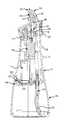
- FIG. 1 is an isometric view of the powered irrigator of the present invention.
- FIG. 2 is an elevation view of the powered irrigator of the present invention with another embodiment of a nozzle.
- FIG. 3 is a section taken through the irrigator of FIG. 2 .
- FIG. 4 is an enlarged section similar to FIG. 3 .
- FIG. 5 is a section view similar to FIG. 4 .
- FIG. 6 is a partial section view similar to FIG. 5 with the diaphragm pump at the end of the intake stroke.
- FIG. 7 is a partial section view similar to FIG. 6 , with the diaphragm pump at the end of the compression stroke.
- FIG. 8 is a partial section view similar to FIG. 7 .
- FIG. 9 is an isometric view of the powered irrigator with the reservoir removed.
- FIG. 10 is an isometric view of the reservoir of the powered irrigator.
- FIG. 11 is a section view of the lower portion of the handle and the reservoir attached by a bayonet connection around the bottom rim of the handle and the top rim of the reservoir.
- FIG. 12 is an isometric view of another powered irrigator of the present invention.
- FIG. 13 is an isometric view of the reservoir of the powered irrigator of FIG. 12 .
- FIG. 14 is an isometric view of the handle of the powered irrigator if FIG. 12 .
- FIG. 15 is a partial section taken through the irrigator of FIG. 12 .
- FIG. 16 is a section view of taken through the irrigator of FIG. 12 .
- FIG. 17 is a section view of the irrigator of FIG. 1 with the nozzle of FIG. 2 .
- FIG. 18A is a top perspective isometric view of the nozzle of FIG. 2 removed from the powered irrigator.
- FIG. 18B is a top plan view of the nozzle illustrated in FIG. 18A .
- FIG. 18C is a side elevation view of the nozzle illustrated in FIG. 18A .
- FIG. 18D is a bottom plan view of the nozzle illustrated in FIG. 18A .
- FIG. 18E is a bottom isometric view of the nozzle illustrated in FIG. 18A .
- FIG. 19 is a section of the nozzle illustrated in FIG. 18A , viewed along line 19 - 19 in FIG. 18B .
- FIGS. 1 and 2 show a powered irrigator 100 for use in rinsing a user's nasal cavities.
- the irrigator has a main body 110 formed by a top handle portion 112 and a bottom reservoir portion 114 .
- the handle portion 112 includes a pump mechanism 116 , power source 118 for the pump mechanism 116 , fluid flow paths 120 for the fluid to pass up to, through, and from the pump mechanism 116 , a switch 122 operably connected to the power source 118 to turn the pump 116 on and off, and a nozzle 124 at the outlet end 126 of the fluid flow paths 120 to comfortably engage and seal with a user's nostril to direct the fluid under pressure into the sinus cavities of the user.
- the reservoir portion 114 is releasably connected to the top handle portion 112 and holds the rinse solution.
- a fluid supply tube 128 extends from the pump mechanism 116 into the reservoir portion 114 to draw the rinse solution out of the reservoir portion 114 and into the pump mechanism 116 .
- the main body 110 has a profiled shape 130 along its length.
- the width and depth dimension of the reservoir portion 114 is relatively large and rounded about its perimeter.
- the bottom of the reservoir 114 is relatively flat to allow the main body to sit upright on a support surface.
- the dimensions of the main body 110 smoothly decrease to a narrower structure 132 which fits well in the hand.
- Two contour grip features 134 , 136 are positioned below the switch 122 for a user's fingers to engage. The body contours to a minimum dimension 138 approximately in the same position as the top grip feature 136 , and then begins to widen out again until the top 140 of the main body, where it flares outwardly.
- the switch 122 is positioned just below the rim 142 of the top 140 of the main body.
- the switch 122 is spring-loaded to thus be actuated upon compression by a user, and automatically terminate actuation upon being released.
- the top 140 of the main body is planar, and extends or tapers down at an angle facing away from the side where the switch 122 is positioned.
- the nozzle 124 extends at an angle ⁇ , which may be approximately at 90 degrees from the main body 110 top surface 144 , and thus at an angle from the longitudinal axis L of the main body 110 . This angle between the nozzle extension and the longitudinal axis of the main body allows for a comfortable and convenient orientation of the irrigator 100 relative to a user's nose and face.
- the angle between the longitudinal axis of the main body 110 and the nozzle 124 extends at an angle ⁇ , which may be about 16 degrees to about 20 degrees, or abut 17.5 degrees.
- the nozzle 124 is removable from an end portion 145 formed at the top 140 of the pump mechanism.
- the nozzle 124 is positioned on the end portion 145 and thus is disposed very near the top surface 144 of the top end 140 of the irrigator 100 . This allows for accurate positioning of the nozzle 124 in the user's nostril without the distraction of the nozzle 124 being on the end of a longer jet tip as is known.
- the nozzle 124 has a collapsible skirt wall 146 (see FIG. 4 ) for a comfortable fit in the user's nostril. This is described in greater detail below.
- the low profile positioning of the nozzle 124 on the top 140 of the handle portion 112 provides for a more secure positioning of the nozzle 124 .
- the nozzle 124 does not extend up from the top surface 144 of the handle 112 more than approximately two height dimensions of the nozzle.
- the nozzle 124 has an outer skirt wall 146 having a bottom rim that is free to move, the outer skirt wall 146 will provide a better peripheral fit with the nostril sidewall since the skirt walls 146 are only engaged at the tip 149 and are free to move and flex without being engaged at the free lower end of the outer skirt wall 146 .
- the outer skirt wall 146 can compress and flex uniquely into the void 205 space between the inner collar 147 of the nozzle 124 (see FIG. 4 ) and the outer skirt wall 146 of the nozzle 124 and into the void 205 space formed between the skirt wall 146 and the crown 228 formed on the top surface of the irrigator, described below.
- FIG. 2 shows the irrigator 100 with a faceted nozzle 410 having a faceted surface that allows the nozzle to create a seal within the nasal cavity better than an oval or purely round nozzle.
- the faceted or circumferentially stepped nozzle external surface is made up of regions having flat extensions or mixed flat and curved extensions, as the faceted nozzle 410 extends downwards.
- the faceted nozzle 410 is self-sealing and is made of a soft elastomeric material, such as food grade silicone rubber.
- FIG. 3 is a cross section of the irrigator 100 , and shows reservoir portion 114 releasably connected to a bottom rim of the top handle portion 112 by a bayonet latch mechanism 148 .
- the fluid supply tube 128 extends from the reservoir portion 114 into the pump mechanism 116 positioned centrally in the handle portion 112 .
- the pump mechanism 116 is powered by a motor 150 , which, as shown in FIG. 4 , drives a gear train 152 to actuate an offset cam mechanism 154 , which rotates around a cam shaft 156 .
- a cam follower 158 is trained around the cam mechanism 154 , and causes the diaphragm 160 to move linearly (i.e., transversely to the longitudinal axis of the irrigator 100 ) within the compression chamber 162 , between an intake stroke and a compression stroke, as is described in more detail below.
- the main body 110 also includes a power source 118 such as a battery (or batteries).
- the power source 118 is connected to the motor 150 and the switch 122 to activate the power source 118 upon actuation of the switch 122 .
- the motor 150 has an output shaft 170 that drives a gear train 152 , which drives the cam shaft 156 as noted above.
- a fluid supply tube 128 extends from the handle into the reservoir to allow fluid to be drawn from the reservoir into the pump mechanism 116 upon actuation of the motor 150 .
- FIGS. 4 and 5 show the pump mechanism 116 and related structure in more detail.
- the gear train 152 turns such that a gear on the end of the shaft turns a larger gear in a gear reduction relationship.
- the larger gear of the gear train 152 turns a cam shaft 156 , which in turn rotates the offset cam mechanism 154 that rotates with the cam shaft 156 .
- the cam shaft 156 ends are supported in a bearing relationship with a part of the pump mechanism housing 172 located inside the handle 112 .
- the offset cam mechanism 154 is entrained in a cam follower 158 .
- the cam follower 158 includes a pushrod 174 that is connected at one end to the diaphragm 160 positioned in the compression chamber 162 of the pump mechanism 116 .
- the actuation of the cam follower 158 by the offset cam mechanism 154 causes the pushrod 174 to move the diaphragm 160 from an intake stroke (shown in FIG. 6 to a compression stroke (shown in FIGS. 7 and 8 ) and back, repeatedly.
- the chamber 180 in the pump mechanism is divided into two regions by the diaphragm 160 .
- the first region 182 behind the diaphragm 160 is primarily to allow the movement of the pushrod 174 and typically does not have fluid in it.
- the region on the other side of the diaphragm is the compression chamber 162 .
- the diaphragm 160 moves toward the first region 182 and enlarges the compression chamber 162 .
- a vacuum is formed.
- the fluid supply tube 128 is in fluid communication with the compression chamber 162 at a fluid inlet 184 .
- An inlet check valve 186 is positioned operably in the connection between fluid supply tube 128 and the compression chamber 162 at the fluid inlet 184 to allow fluid to flow into the compression chamber 162 from the supply tube 128 , but not out of the compression chamber 162 into the supply tube 128 .
- the inlet check valve 186 is open when the diaphragm 160 moves from the compression stroke to the inlet stroke.
- an outlet conduit 190 extends from the compression chamber 162 to a connection portion 192 having a channel 194 formed there through.
- One end of the connection portion 192 is sealingly engaged with the outlet conduit 190 .
- the other end of the connection portion 192 forms the end portion 145 that receives the nozzle 124 as described above and in more detail below.
- An outlet check valve 196 is positioned between the end of the outlet conduit and the channel 194 of the connection portion 192 .
- the check valve 196 is open when the pump mechanism 116 moves from the intake stroke through the compression stroke, and is closed when the diaphragm 160 moves from the compression stroke through the intake stroke.
- the outlet check valve 196 also forms an anti-backflow device to help keep any residual fluid from the nasal passage from flowing back into the pump mechanism 116 .
- a vacuum is formed, which closes the outlet check valve 196 and opens the inlet check valve 186 to allow fluid to be drawn into the compression chamber 162 .
- the positive pressure in the compression chamber 162 causes the inlet check valve 186 to close and the outlet check valve 196 to open, which allows the fluid to be pushed out of the compression chamber 162 and into the outlet conduit 190 .
- the fluid flows through the outlet check valve 196 into the channel 194 in the connection portion 192 .
- This channel 194 may have a diameter of 0.110 inches, and is what primarily controls the pressure flow of the outlet flow.
- the pump mechanism 116 runs at about 2000-3000 cycles per minute, with a flow rate of about 500 to 600 ml per minute.
- the geometry of the flow path 120 creates a relatively low back pressure of approximately 5 psi.
- This type of pump mechanism 116 is efficient, and allows the generation of the appropriate fluid flows and pressures while drawing relatively little current from the power source 118 , such as batteries.
- Such a pump mechanism 116 may be described as a positive displacement pump that uses a diaphragm.
- the power source 118 may be permanent, rechargeable or replaceable.
- FIG. 6 shows the diaphragm at the end of the intake stroke, where the compression chamber 162 now contains fluid drawn in from the reservoir portion 114 through the supply tube 128 and the open inlet check valve 186 .
- FIGS. 7 and 8 show the diaphragm 160 at the end of the compression stroke, where the fluid has been pushed out of the compression chamber 162 and through the outlet conduit 190 past the outlet check valve 196 into the connection portion 192 and out the aperture 198 of the nozzle 124 . In this position, of the diaphragm 160 , the inlet check valve 186 is closed, thereby preventing fluid from entering or exiting the inlet check valve 186 .
- FIG. 9 shows the handle portion 112 of the irrigator 100 with the reservoir portion 114 removed.
- the fluid supply tube 128 extends from the end of the handle portion 112 to be positioned in the reservoir portion 114 to draw fluid therefrom.
- the end of the handle portion 112 includes at least one bayonet latch component 210 , in this example a slot 212 for receiving the bayonet tabs 214 formed on the upper rim of the reservoir portion 114 (see FIG. 10 ).
- the slot 212 is formed on a rim 216 that extends down from the bottom panel 218 of the handle portion 112 .
- the rim 216 fits within the upper edge 220 of the reservoir portion 114 .
- the power source 118 such as batteries may be replaced in this embodiment by removing the bottom panel 218 of the handle portion 112 to open a cavity 222 (see FIG. 3 ) for receiving the batteries.
- a sealing element 223 such as an o-ring.
- the bottom of the handle portion 112 may include a sealing element 223 disposed thereon facing the bottom panel 218 so that when the bottom panel 218 is attached after receiving batteries, a fluid tight seal is provided.
- the bottom panel 218 may also include a sealing element 219 , such as a D-ring disposed within an interior portion of the bottom panel 218 , and a protruding wall forming the cavity 222 extending from the bottom of the handle portion 112 may be shaped complementarily to the shape of the sealing element 219 to contact an internal circumference of the sealing element 219 .
- a fluid tight seal may thus be provided between the protruding wall of the handle portion 112 and the bottom panel 218 to prevent fluids from entering the cavity 222 .
- FIG. 10 shows the reservoir portion 114 removed from the bottom of the handle portion 112 .
- the upper edge 220 of the reservoir portion 114 forms at least one tab 214 on its inner diameter 224 to be received in at least one slot 212 on the bottom of the handle portion 112 to secure the reservoir portion 114 to the handle portion 112 .
- the tab 214 is secured in the slot by aligning the tab(s) 214 with the slot(s) 212 and rotating the reservoir with respect to the handle to engage the tab 214 in the slot 212 . In this way, the entire bottom portion of the main body 110 may be removed to fill the reservoir portion 114 with fluid.
- the reservoir has a wide opening to make filling the reservoir relatively simple.
- FIG. 11 shows a cross section of the bayonet latch mechanism 148 in which an assembled engagement is provided between the slot 212 of the handle portion 112 and the tab 214 of the reservoir portion 114 .
- the fluid supply tube 128 may be continuous, or may extend through the bottom panel 218 of the handle portion 112 by a tubular fitting 225 .
- the end portion 145 is formed at an exterior surface of the irrigator 100 , receives the nozzle 124 .
- the end portion 145 includes both the distal end of the connection portion 192 and the crown 228 .
- the connection portion 192 forming a part of the end portion 145 is an exposed distal end that extends through the crown 228 .
- the proximal end of the connection portion 192 is recessed within and sealingly engages with the handle portion 112 , and at a terminal end, the connection portion 192 engages with the distal end of the outlet conduit 190 , described above.
- the end portion 145 extends or protrudes upwardly from the angled top surface 144 of the irrigator and receives the nozzle 124 .
- the end portion 145 at the proximal end of the crown 228 includes a base section 240 having a first diameter, a shoulder 242 formed annularly around the base section 240 extending to a decreased diameter to form a first portion 244 of the end portion 145 , which then transitions into the conical section 246 extending further away from the base section 240 and tapering down and decreasing the diameter even further until the second portion 248 formed by the connection portion 192 , where the second portion 248 forms a cylindrical wall and extends away from the conical section 246 .
- An annular rib 250 is formed on the outer diameter of the second portion 248 .
- the base section 240 , first portion 244 and the second portion 248 are generally cylindrical in shape, with the inner diameters and outer diameters being largest at the base portion 240 , somewhat smaller for the second portion 244 , decreasing with the angle of the conical section 246 , down to the size of the second portion 248 .
- the conical section 246 is formed by both the tapering portion of the crown 228 as well as a tapering proximal section of the exposed connection portion 192 .
- the outer diameter of the second portion 248 forming the annular rib 250 is about the same diameter as the inner diameter of the inner collar 147 of the nozzle such that when the nozzle 124 is positioned over the second portion 248 , the inner collar 147 of the nozzle engages the outer walls of the second portion 248 , and the rib 250 of the second portion 248 snaps into the annular channel 252 formed in the inner diameter of the inner collar 147 to hold the nozzle 124 onto the end portion 145 at a predefined position.
- This engagement structure 254 allows secure placement of the nozzle 124 on top of the end portion 145 , but allows it to be removed for cleaning or replacement if desired.
- the aperture 198 of the engagement tip 149 aligns with the aperture 210 formed in the second portion 248 of the end portion 145 .
- the terminal edge 230 of the inner collar 147 of the nozzle may engage the outer wall of the conical section 246 somewhat near the intersection between the conical section 246 and the second portion 248 of the end portion 145 .
- the terminal edge 230 of the inner collar 147 may be beveled at an angle complementary to the angle of the conical section 246 of the end portion 145 to connect with the conical section 196 and to provide sealing.
- the engagement of the terminal edge 230 of the inner collar 147 provides additional sealing to help keep the fluid flowing through the end portion 145 and the nozzle 124 and from passing between the engagement of the nozzle 124 and the second portion 248 .
- the end of the second portion 248 also engages a shoulder 258 formed in the tip 149 of the nozzle, with the shoulder 258 being formed around the aperture 198 extending through the tip 149 .
- the tip 149 of the nozzle is solid in the area surrounding the aperture 198 extending through the tip 149 .
- the outer wall extending downwardly and away from the tip 149 forms an outer skirt 146 , starting at about the position from where the inner collar 147 extends downwardly from the base of the tip 149 .
- An annular spacing or void 205 is formed between the outer skirt 146 and the inner collar 147 and between the outer skirt 146 and the conical section 246 . That is, the void space 205 is formed in the area of the nozzle 124 between where the outer skirt 146 and inner collar 147 extend down, and because the wall forming the outer skirt 146 extends further from the tip 149 than does the wall forming the inner collar 147 , the continuing void 205 is formed between the skirt 146 and conical section 246 beyond the terminal edge 230 of the inner collar 147 .
- the terminal edge 260 of the skirt 146 is positioned around the first portion 244 of the end portion 145 .
- the terminal edge 260 of the skirt, as well as the adjacent wall structure of the skirt 146 closely fits with the first portion 244 of the end portion but does not necessarily engage the first portion 244 . Also, a gap 262 may be formed between the shoulder 242 extending between the base portion 240 and the first portion 244 and the terminal edge 260 of the skirt.
- the terminal edge 206 of the skirt 146 does not attach to or otherwise affix to the first portion 194 of the end portion 145 and may move relative thereto.
- the inner collar 147 connects to the end portion 145 at a position closer to the tip 149 of the nozzle and is spaced above the edge of the skirt wall.
- the nozzle 124 is made of a soft elastomeric material, such as food grade silicone rubber.
- the skirt 146 when positioned in the user's nasal passage, flexes inwardly into the void space 205 formed between the skirt 146 and the inner collar 147 and the void space 205 between the skirt 146 and the conical section 246 and may do so radially and/or irregularly around its circumference in order to closely match the shape of the user's nostril. This helps create an adequate seal between the user's nostril and the self-sealing nozzle structure.
- the nozzle 124 is removed from the user's nostril, the elastomeric material springs back into its original shape.
- the wall thickness of the skirt 146 is 0.040 inches and the wall thickness of the inner collar 147 is 0.060 inches.
- the gently curving, cone-like shape of the nozzle 124 from the tip 149 down to the terminal edge 260 of the skirt allows for a close fit with a variety of sizes of nasal passages.
- the void space 205 may be annular, or may be discontinuous within the skirt wall.
- One feature that allows the skirt structure to provide an adequate seal for the user's nasal passages is the engagement of the terminal edge 260 of the skirt with the first portion 244 of the end portion 145 .
- the terminal end 260 of the skirt engages the first portion 244 of the end portion 145 and keeps that portion of the skirt 146 from deflecting further inwardly, thus providing some structural rigidity to the flexion of the portion of the skirt 146 extending between the tip and the terminal end.
- the terminal end 260 is not joined to first portion 244 and may move relative thereto.
- FIGS. 12-16 show another embodiment of an irrigator 300 with a main body 310 including a handle portion 312 connected to a reservoir portion 314 .
- the reservoir portion 314 differs from the reservoir portion 114 described above in connection with FIGS. 1-11 by the reservoir portion 314 addition of a locking ring 320 movably held in the reservoir portion by the retaining ring 322 , a tab 324 formed on the locking ring 320 , a reservoir outlet 326 , and a reservoir flip cap 328 covering a reservoir sidewall aperture 330 forming a reservoir inlet.
- the handle portion 312 differs from the handle portion 112 described above in connection with FIGS.
- the handle portion 312 is similar to the handle portion 112 in other respects, and includes a pump mechanism 116 , power source 118 for the pump mechanism 116 , a switch 122 operably connected to the power source 118 to turn the pump 116 on and off, and receives a nozzle 124 (not shown) at the end portion 145 .
- the reservoir part 314 is configured as a substantially enclosed structure forming an inlet and a relatively small outlet.
- the sidewall aperture 330 defines the reservoir inlet for the reservoir part 314 .
- the sidewall aperture 330 includes a sealing ring 336 such as a silicone grommet extending between an interior and an external recessed portion 338 of the reservoir part 314 .
- the sidewall aperture 330 allows the reservoir part be opened when the flip cap 328 is rotated down or flipped away from the reservoir part 314 , and the sidewall aperture 330 is fluidly sealed by the reservoir flip cap 328 (see FIG. 12 ) mating with the sealing ring 336 when the reservoir flip cap 328 is pressed into the recessed portion 338 .
- the user rotates the flip cap 328 away from the recessed portion 338 and pours the rinse solution through the sidewall aperture 330 and into the substantially enclosed interior of the reservoir part 314 .
- the cylindrical tubular-shaped reservoir outlet 326 projects vertically from a top surface 340 of the reservoir part 314 and provides fluid access to the handle portion 312 .
- the reservoir outlet 326 is aligned with the recessed tubular fitting 334 and the handle portion 312 first connects to the reservoir portion 314 by forming a connection by the recessed tubular fitting 334 receiving the reservoir outlet 326 .
- the rim 342 forming the bottom of the handle portion 312 is inserted into an upper circumferential recess 344 formed in the reservoir portion 314 .
- the locking ring 320 is rotatable from an unlocked position to a locked position, and during the fitting process, the locking ring 320 is rotated by a user moving the sliding flange 350 to the unlocked position in which the tab 324 of the locking ring 320 is arranged so that the rim 342 passes into the circumferential recess 344 .
- the user slides the locking ring flange 350 to the locked position in which the tab 324 of the locking ring enters the slot 352 formed in the rim 342 of the handle portion.
- the user is able to identify whether the flange 350 is in a locked or an unlocked position by aligning the flange 350 with the lock and unlock indicia 354 arranged on the external surface of the reservoir portion 314 .
- the locking ring 320 is held on the reservoir portion 314 by the retaining ring 322 .
- FIG. 15 shows a cross-section of the handle portion 312 connected to the reservoir portion 314 in a locked position of the bayonet latch mechanism 358 established between the slot 352 and the rim 342 .
- the tab 324 of the locking ring 320 has been rotated to enter the slot 352 in the handle portion 312 and locks the handle portion 312 to the reservoir portion 314 .
- the bayonet latch mechanism 358 engaged in the locked position prevents the portions from relative rotation and from detaching.
- the flange 350 is simply shifted in the direction transverse to the longitudinal axis of the main body 310 .
- a fluid intake tube 360 connects to a passage 362 of the reservoir outlet 326 at a tubular fitting 364 projecting from a top enclosing wall 366 of the reservoir portion 314 .
- the projecting tubular fitting 364 receives the fluid intake tube 360 within its internal circumference.
- An annular seal 368 is provided around an external circumference of the fluid intake tube 360 and the internal circumference of the tubular fitting 364 in order to facilitate providing a fluid tight connection between the fluid intake tube 360 and the reservoir outlet 326 .
- the reservoir outlet 326 and the recessed tubular fitting 334 of the handle portion 312 establish a fluid tight connection, which is facilitated by the annular seal 370 disposed in an internal circumference of the tubular fitting 334 that seals around the external circumference of the reservoir outlet 326 upon insertion of the reservoir outlet 326 into the tubular fitting 334 .
- the fluid connection 332 of the handle portion 312 includes a projecting tubular fitting 382 that is configured to fit within a fluid passage 384 leading from a bottom of the handle portion 312 to the pump mechanism 116 . Accordingly, when a user presses the switch 122 , the power source 118 actuates the pump mechanism 116 , which draws the rinse solution from the reservoir portion 314 .
- the rinse solution follows a fluid pathway 390 from the fluid intake tube 360 into passage 362 and exits the reservoir portion 314 at the reservoir outlet 326 , which empties into the recessed tubular fitting 334 of the handle portion 312 and continues into the projecting tubular fitting 382 and through the fluid passage 384 .
- the inlet check valve 186 When the inlet check valve 186 is in an opened position, the solution enters the pump mechanism 116 for delivery from the nozzle 124 .
- the reservoir portion 314 includes a sloped floor 386 recessed from the top surface 340 .
- the sloped floor 386 terminates the upper circumferential recess 344 , and encloses the interior of the reservoir portion 314 .
- the sloped floor 386 extends downwardly at an angle as it extends away from the area of the reservoir portion 314 carrying the reservoir outlet 326 .
- the reservoir part forms a slit 388 leading to the exterior of the reservoir portion 314 that extends vertically to the top surface 340 .
- the slit 388 in combination with the downward sloping floor 386 allows fluid escaping the reservoir portion 314 , for example via the reservoir outlet 326 , to be carried by gravity down the sloped floor 386 and out the slit 388 . This allows fluid to escape from the reservoir portion 314 before the fluid can enter the cavity 222 holding the power source 118 .
- the fluid pathway 390 of irrigator 300 differs from the fluid pathway 120 of irrigator 100 .
- the fluid supply tube 128 extends from handle portion 112 into the opening defined by the upper edge 220 of the reservoir portion 114 .
- the fluid pathway 120 of irrigator 100 is substantially provided by components associated with the handle portion 112 .
- the fluid pathway 390 of irrigator 300 includes components within both the handle portion 312 and the reservoir portion 314 .
- the irrigator 300 like the irrigator 100 includes a pump mechanism 116 , power source 118 for the pump mechanism 116 , switch 122 operably connected to the power source 118 to turn the pump 116 , but in irrigator 300 , these components cooperate to draw fluid through fluid pathway 390 described above for delivering the rinse solution from the nozzle.
- FIG. 17 is a section view of the faceted nozzle 410 of FIG. 2 attached to the irrigator 100 by the end portion 145 .
- the faceted nozzle 410 has a skirt 422 that extends outwardly and away from a tip 450 , an inner collar 428 extending downwardly and away from the tip and forms a cylindrical wall 420 creating a conduit or passageway within the inner surface of the faceted nozzle 410 .
- the inner collar 428 may be formed integrally with the skirt 422 .
- the inner collar 428 may terminate at the tip 450 creating the outlet aperture 412 .
- the distal end of the inner collar 428 terminates inside the skirt 422 .
- the inner collar 428 may extend as far as the terminal edge 424 of the skirt 422 and in other implementations (such as the implementation illustrated in FIG. 17 ) the inner collar 428 may have a terminal edge 454 that terminates at a point above the terminal edge 424 of the skirt 422 .
- the wall thickness of the inner collar 428 in some embodiments may be approximately 0.060 inches.
- the inner collar 428 of the faceted nozzle 410 connects with the end portion 145 formed by the crown 228 and the connection portion 192 .
- the faceted nozzle 410 is placed above the end portion 145 and the end portion 145 may be inserted partially into the inner collar 428 .
- the end portion 145 may extend only partially into the inner collar 428 .
- an o-ring (not shown) may be secured within the annular recess 452 to create a fluid-tight seal between the inner collar 428 and the end portion 145 .
- the skirt 422 extends away from the second portion 248 and the inner collar 428 creating a void 440 or open space between the conical section 246 of the end portion 145 and the skirt 422 .
- the void 440 or annular spacing is also formed between the skirt 422 and the inner collar 428 , and the wall forming the skirt 422 extends further from the tip 450 than does the wall forming the inner collar 428 such that the terminal edge 424 of the skirt 422 is positioned around a cylindrical first portion 244 of the end portion 145 .
- the void space 440 may be annular and may be continuous or discontinuous within the skirt wall.
- the terminal edge 424 of the skirt 422 may closely fit with the cylindrical first portion 244 of the end portion 145 , but not necessarily engage with the cylindrical first portion 244 . Also, a small gap 418 may be formed between the shoulder 242 of the end portion 145 and the terminal edge 424 of the skirt 422 . As discussed above, the terminal edge 424 of the skirt 422 may not attach to or otherwise be affixed to the cylindrical first portion 244 and may move relative thereto. In other implementations the skirt 422 may rest along the cylindrical first portion 244 or otherwise contact the cylindrical first portion 244 of the end portion.
- the inner collar 428 extends downward from the outlet aperture 412 and may mate and fluidly connect with the end portion 145 , attaching the faceted nozzle 410 to the irrigator 100 .
- the inner collar 428 may include an annular recess 452 along its inner walls to receive the circumferential rib 250 on the second portion 248 of the end portion 145 .
- the terminal edge 454 of the inner collar 428 may be beveled at an angle complementary to the angle of the conical section 246 of the end portion 145 to connect with the conical section 196 and to provide sealing.
- the terminal edge 454 of the inner collar 428 may connect with the conical section 246 to provide additional sealing and help keep the fluid flowing through the end portion 145 and the faceted nozzle 410 and prevent fluid from passing between the engagement of the faceted nozzle 410 and the second portion 148 .
- the tip 450 of the faceted nozzle 410 above the annular recess 452 extends down to a cylindrical wall 420 that defines the outlet aperture 412 and the tip 450 may be thicker than the wall of the inner collar 428 , the inner collar 428 thus may have a larger inner diameter than the cylindrical wall 420 forming the outlet aperture 412 .
- a shoulder 426 formed in the tip 450 of the faceted nozzle 410 may be formed around the aperture 412 and engage with the end of the second portion 248 of the end portion 145 .
- FIG. 18A is a top isometric view of the faceted nozzle 410 ;
- FIG. 18B is a top plan view of the faceted nozzle 410 ;
- FIG. 18C is a side elevation view of the faceted nozzle 410 ;
- FIG. 18D is a bottom plan view of the faceted nozzle 410 ;
- FIG. 18E is a bottom isometric view of the faceted nozzle 410 ;
- FIG. 19 is a cross-section view of the faceted nozzle 410 , as indicated by line 19 - 19 in FIG. 18C .
- the faceted nozzle 410 is self-sealing and is made of a soft elastomeric material, such as food grade silicone rubber.
- the nozzle 410 includes a tip 450 or apex which is the first portion of the nozzle 410 to enter the user's nostril when attached to the irrigator 100 .
- At a center portion of the tip 450 is an outlet aperture 412 .
- a skirt 422 or body is formed by a wall extending downwardly and away from the tip 450 , as can be see from FIG. 18A , the skirt 422 is faceted or stepped circumferentially, or otherwise made up of regions having flat extensions or mixed flat and curved extensions, as the skirt 422 extends downwards.
- the skirt 422 may have a wall thickness of approximately 0.040 inches.
- the skirt 422 of the faceted nozzle 410 acts to form a seal with the user's nostril when the faceted nozzle 410 is attached to the irrigator 100 .
- the skirt 422 includes steps 446 a - 446 e , which create ridges on the outer surface of the skirt 422 .
- the steps 446 a - 446 e may be approximately the same height; however each step 446 a - 446 e may have a different average or center diameter.
- each step 446 a - 446 e increases the overall outer diameter of the skirt 422 and the faceted nozzle 410 maintains a generally rounded shape.
- the first step 446 a has a smaller average diameter than the second step 446 b , and so on.
- the steps 446 a - 446 e may have different widths, such that the first step 446 a may cover a greater portion of the outer surface of the skirt 422 than the second step 446 b.
- the steps 446 a - 446 e may be a series of stacked frustums having different outer wall angles.
- Each step 446 a - 446 e is sloped at a predetermined angled and the outer wall has a larger diameter at the bottom edge of the steps 446 a - 446 e than at the top edge of each step 446 a - 446 e .
- each step 446 a - 446 e decreases in diameter from the bottom edge to the top edge.
- each step 446 a - 446 e may have a different average diameter than the preceding step 446 a - 446 e ; this is because each step 446 a - 446 e may have a different outer wall angle than the previous step 446 a - 446 e .
- the configuration of stacked frustum sections on top of one another may include ridges between each of the steps 446 a - 446 e at the point of transition, from one step 446 a - 446 e to the next; this gives the skirt 422 a faceted appearance and feel.
- the user inserts the tip 450 into a user's nostril and then actuates the irrigator 100 , allowing the solution to travel from the main body 110 to the end portion 145 .
- the solution enters the inner collar 428 proximate the tip 450 and exits into the nasal cavity via the outlet aperture 412 .
- the faceted nozzle 410 creates a seal between the nostril wall and the skirt 422 via the facets or steps 446 a - 446 e , the nasal solution is deposited into the nasal cavity without substantially leaking around the faceted nozzle 410 and the user's nostril.
- one of the steps 446 a - 446 e creates a seal between the faceted nozzle 410 and the nostril walls.
- the particular step 446 a - 446 e that engages the user's nostril depends upon the size of the user's nostril. For example, the larger the user's nostril the lower the step 446 a - 446 e may be that engages the nostril wall.
- the steps 446 a - 446 e create a better seal than a purely rounded nozzle, as the steps 446 a - 446 e better conform to the nostril wall—the nostril wall is not purely oval-shaped or conical-shaped—and the steps 446 a - 446 e better mimic the inner surface of the nostril wall. It should be noted that although five steps 446 a - 446 e have been illustrated, any number of steps 446 a - 446 e may be included. The number of steps 446 a - 446 e may be altered to create a smoother or rougher skirt 422 . For example, depending on the desired sealing level the number of steps 446 a - 446 e may be increased or decreased.
- the skirt 422 when positioned in the user's nasal passage, flexes inwardly into the void 440 formed as the skirt 422 extends away from the connection between the faceted nozzle 410 and the second portion 248 of the end portion 145 .
- the skirt 422 may do so irregularly around its circumference in order to closely match the shape of the user's nostril. This helps create an adequate seal between the user's nostril and the faceted nozzle 410 structure.
- the elastomeric material of the skirt 422 springs back into its original shape.
- the gently curving, cone-like shape of the faceted nozzle 410 from the tip 450 down to the terminal edge 424 of the skirt 422 allows for a close fit with a variety of sizes of nasal passages.
- the skirt 422 terminates at a terminal edge 424 .
- the terminal edge 424 may be a continuation of the steps 446 a - 446 e and in other embodiments the terminal edge 424 may extend past the steps 446 a - 446 e creating a shoulder, flange, or the like.
- the faceted nozzle 410 may be substantially free-standing along the skirt 422 , i.e., the skirt 422 and/or other outer surfaces of the faceted nozzle 410 may be substantially unrestricted. As can be seen from FIG. 17 , the terminal edge 424 is unrestricted by the first portion 194 of the end portion 145 .
- the user may rinse her nasal cavities using the irrigators 100 , 300 provided herein, and may use the nozzle 124 and the faceted nozzle 410 on either irrigator 100 and 300 .
- the index finger can control the switch 122 , with the middle and ring finger engaging the finger grips.
- the user then can hold the nozzle 124 , 410 in line with the user's right nostril, with the irrigator 100 , 300 underneath the user's nose, for easy insertion of the nozzle 124 , 410 into the user's right nostril for the rinse operation.
- the nozzle 124 , 410 due to its position on the angled top surface 144 of the handle is angled away from the user's septum and towards a right or outer wall of the right nostril.
- the user may hold the irrigator 100 , 300 in her left hand, with the index finger on the switch 122 , and the middle and ring finger on the finger grips.
- the nozzle 124 , 410 can then be positioned in line with the user's left nostril, with the main body of the irrigator 100 , 300 extending down past the user's left cheek.
- the nozzle 124 , 410 can then be positioned in the user's left nostril for the rinse operation.
- the main body 110 , 310 has a rigid construction, and the main body 110 , 310 or portions thereof may be composed of plastic or other polymers, composites, non-corrosive metals, and/or combinations thereof. Components may be molded, extruded, laser cut, or otherwise formed into the desired shape.
- the powered irrigators of the present invention allow a user to irrigate her nasal cavity without using a gravity-fed supply vessel, which may be more comfortable. While the methods disclosed herein have been described and shown with reference to particular steps performed in a particular order, it will be understood that these steps may be combined, subdivided, or re-ordered to form an equivalent method without departing from the teachings of the present invention. Accordingly, unless specifically indicated herein, the order and grouping of the steps are not generally intended to be a limitation of the present invention.
- references herein to “up” or “top”, “bottom” or “down”, “lateral” or “side”, and “horizontal” and “vertical”, as well as any other relative position descriptor are given by way of example for the particular embodiment described and not as a requirement or limitation of the powered irrigator or the apparatus and method for assembling the powered irrigator.
- Reference herein to “is”, “are”, “should”, “would”, or other words implying a directive or positive requirement are intended to be inclusive of the permissive use, such as “may”, “might”, “could” unless specifically indicated otherwise.
Landscapes
- Health & Medical Sciences (AREA)
- Engineering & Computer Science (AREA)
- Anesthesiology (AREA)
- Biomedical Technology (AREA)
- Heart & Thoracic Surgery (AREA)
- Hematology (AREA)
- Life Sciences & Earth Sciences (AREA)
- Animal Behavior & Ethology (AREA)
- General Health & Medical Sciences (AREA)
- Public Health (AREA)
- Veterinary Medicine (AREA)
- Infusion, Injection, And Reservoir Apparatuses (AREA)
Abstract
Description
- This continuation application claims under 35 U.S.C. §120 the benefit of U.S. patent application Ser. No. 12/970,345, entitled “Powered Irrigator for Sinus Cavity Rinse” and filed Dec. 16, 2010; as a continuation-in-part of U.S. design application No. 29/352,098, entitled “Powered Irrigator for Sinus Cavity Rinse” and filed Dec. 16, 2009, and as a continuation-in-part of U.S. design application No. 29/364,670 entitled “Faceted Nasal Seal” and filed Jun. 25, 2010, the disclosures of which are hereby incorporated by reference in their entireties. This application claims under 35 U.S.C. §119(e) the benefit of U.S. provisional application No. 61/287,100, entitled “Powered Irrigator for Sinus Cavity Rinse” and filed Dec. 16, 2009, U.S. provisional application No. 61/287,026, entitled “Vessel for Sinus Cavity Rinse” and filed Dec. 16, 2009, and U.S. provisional application No. 61/369,378, entitled “Faceted Nasal Seal” and filed Jul. 30, 2010, the disclosures of which are hereby incorporated by reference in their entireties.
- This application is related to U.S. patent application No. ______, entitled “Pump for Powered Irrigator for Sinus Cavity Rinse,” filed Jul. 10, 2012 and having Attorney Docket No. P201813.US.05; U.S. application Ser. No. 12/970,610, entitled “Pot for Sinus Cavity Rinse” filed Dec. 16, 2010, and U.S. patent application Ser. No. 12/970,788, entitled “Bottle for Sinus Cavity Rinse” filed Dec. 16, 2010, and U.S. patent application Ser. No. 12/970,854, entitled “Faceted Nasal Seal” filed Dec. 16, 2010, and U.S. patent application Ser. No. 12/970,415, entitled “Squeeze Bottle for Sinus Cavity Rinse” filed Dec. 16, 2010, and U.S. design application No. 29/381,243, entitled “Powered Irrigator for Sinus Cavity Rinse” filed Dec. 16, 2010, the disclosures of which are herein incorporated by reference in their entireties.
- This invention relates to powered irrigators for use in rinsing one's sinus cavities.
- The benefits of rinsing one's sinus cavities have been well established, and include improving resistance to sinus infections, clogged sinuses, allergies, and general health. Oftentimes, however, the articles which one uses to rinse their sinus cavities are difficult to use and make the process unnecessarily difficult and uncomfortable. One of the issues is related to the inability to obtain an effective seal between the nozzle of one of these articles and the user's nasal passage. If the seal is not adequate, during use the fluid can leak from between the nozzle and the nasal passage, thereby making the rinsing process messy.
- In addition, the vessels used for sinus rinsing can be difficult to use, and sometimes require challenging coordination. The flow control of the flow from the vessel into the nasal passage has not been adequate in the past, and users have found it difficult to regulate the volume of flow so as to make the rinsing process comfortable. Typical products utilize either gravity flow from a generally large volume of water flowing out of a vessel, or pressurized flow from a squeeze bottle. Both are difficult to accurately control how much liquid is used, and when the liquid flow starts and stops. These products can also require hand strength and dexterity not available to some individuals. And, these products can require bending over a sink or other receptacle at an odd angle, which may be challenging for users with limited flexibility.
- It is to satisfy the above-recognized issues that the present invention has been developed.
- The present invention relates to a powered nasal cavity irrigator that includes a main body having a detachably connected handle portion and reservoir portion. The handle portion includes a pump mechanism, power source, and switch for turning on and off the power source to actuate the pump mechanism. Fluid flows from the reservoir portion through the handle portion and out a nozzle disposed at the handle portion upon actuating the pump mechanism. The reservoir includes a generally cylindrical body defining a cavity; and at least two tabs operably connected to the cylindrical body and extending inwards from the cylindrical body towards the cavity. The at least two tabs operably connect the reservoir to the handle portion to releasably secure the reservoir to the handle portion.
- The powered nasal cavity irrigator, in one embodiment, includes a rigidly constructed main body having a handle and fluid reservoir detachably connected to each other. An outlet nozzle extends from a top end of the handle. A pump mechanism operably couples to a power source, and a switch is operably couples to the power source for turning the pump mechanism on and off. The switch is arranged at an external surface of the handle, and when the switch turns on the pump mechanism, fluid flows from the fluid reservoir into a first fluid coupling between the reservoir and the pump mechanism and into a second fluid coupling between the pump mechanism to the outlet nozzle.
- In another embodiment, a powered nasal cavity irrigator includes a rigidly constructed main body including a handle and fluid reservoir. The handle and the fluid reservoir are detachably connected to each other. A top end of the handle provides a portion being angled relative to a longitudinal axis of the main body. An outlet nozzle extends from the top end of the handle at a substantially right angle to the angled portion of the top end. A pump mechanism operably couples to a power source, and switch operably couples to the power source for turning the pump mechanism on and off. The switch is arranged at an external surface of the handle, and when the switch turns on the pump mechanism, fluid flows from the fluid reservoir into a first fluid coupling between the reservoir and the pump mechanism and into a second fluid coupling between the pump mechanism to the outlet nozzle.
- The features and advantages of the present invention will be more readily apparent from the following detailed description, illustrated by way of example in the drawing figures, wherein:
-
FIG. 1 is an isometric view of the powered irrigator of the present invention. -
FIG. 2 is an elevation view of the powered irrigator of the present invention with another embodiment of a nozzle. -
FIG. 3 is a section taken through the irrigator ofFIG. 2 . -
FIG. 4 is an enlarged section similar toFIG. 3 . -
FIG. 5 is a section view similar toFIG. 4 . -
FIG. 6 is a partial section view similar toFIG. 5 with the diaphragm pump at the end of the intake stroke. -
FIG. 7 is a partial section view similar toFIG. 6 , with the diaphragm pump at the end of the compression stroke. -
FIG. 8 is a partial section view similar toFIG. 7 . -
FIG. 9 is an isometric view of the powered irrigator with the reservoir removed. -
FIG. 10 is an isometric view of the reservoir of the powered irrigator. -
FIG. 11 is a section view of the lower portion of the handle and the reservoir attached by a bayonet connection around the bottom rim of the handle and the top rim of the reservoir. -
FIG. 12 is an isometric view of another powered irrigator of the present invention. -
FIG. 13 is an isometric view of the reservoir of the powered irrigator ofFIG. 12 . -
FIG. 14 is an isometric view of the handle of the powered irrigator ifFIG. 12 . -
FIG. 15 is a partial section taken through the irrigator ofFIG. 12 . -
FIG. 16 is a section view of taken through the irrigator ofFIG. 12 . -
FIG. 17 is a section view of the irrigator ofFIG. 1 with the nozzle ofFIG. 2 . -
FIG. 18A is a top perspective isometric view of the nozzle ofFIG. 2 removed from the powered irrigator. -
FIG. 18B is a top plan view of the nozzle illustrated inFIG. 18A . -
FIG. 18C is a side elevation view of the nozzle illustrated inFIG. 18A . -
FIG. 18D is a bottom plan view of the nozzle illustrated inFIG. 18A . -
FIG. 18E is a bottom isometric view of the nozzle illustrated inFIG. 18A . -
FIG. 19 is a section of the nozzle illustrated inFIG. 18A , viewed along line 19-19 inFIG. 18B . -
FIGS. 1 and 2 show apowered irrigator 100 for use in rinsing a user's nasal cavities. The irrigator has amain body 110 formed by atop handle portion 112 and abottom reservoir portion 114. As shown inFIG. 3 , thehandle portion 112 includes apump mechanism 116,power source 118 for thepump mechanism 116,fluid flow paths 120 for the fluid to pass up to, through, and from thepump mechanism 116, aswitch 122 operably connected to thepower source 118 to turn thepump 116 on and off, and anozzle 124 at theoutlet end 126 of thefluid flow paths 120 to comfortably engage and seal with a user's nostril to direct the fluid under pressure into the sinus cavities of the user. Thereservoir portion 114 is releasably connected to thetop handle portion 112 and holds the rinse solution. Afluid supply tube 128 extends from thepump mechanism 116 into thereservoir portion 114 to draw the rinse solution out of thereservoir portion 114 and into thepump mechanism 116. - The
main body 110 has a profiledshape 130 along its length. The width and depth dimension of thereservoir portion 114 is relatively large and rounded about its perimeter. The bottom of thereservoir 114 is relatively flat to allow the main body to sit upright on a support surface. At or just above where thereservoir 114 connects to thehandle 112, the dimensions of themain body 110 smoothly decrease to anarrower structure 132 which fits well in the hand. Two contour grip features 134, 136 are positioned below theswitch 122 for a user's fingers to engage. The body contours to aminimum dimension 138 approximately in the same position as thetop grip feature 136, and then begins to widen out again until the top 140 of the main body, where it flares outwardly. Theswitch 122 is positioned just below therim 142 of the top 140 of the main body. Theswitch 122 is spring-loaded to thus be actuated upon compression by a user, and automatically terminate actuation upon being released. The top 140 of the main body is planar, and extends or tapers down at an angle facing away from the side where theswitch 122 is positioned. Thenozzle 124 extends at an angle α, which may be approximately at 90 degrees from themain body 110top surface 144, and thus at an angle from the longitudinal axis L of themain body 110. This angle between the nozzle extension and the longitudinal axis of the main body allows for a comfortable and convenient orientation of theirrigator 100 relative to a user's nose and face. The angle between the longitudinal axis of themain body 110 and thenozzle 124 extends at an angle θ, which may be about 16 degrees to about 20 degrees, or abut 17.5 degrees. - The
nozzle 124 is removable from anend portion 145 formed at the top 140 of the pump mechanism. Thenozzle 124 is positioned on theend portion 145 and thus is disposed very near thetop surface 144 of thetop end 140 of theirrigator 100. This allows for accurate positioning of thenozzle 124 in the user's nostril without the distraction of thenozzle 124 being on the end of a longer jet tip as is known. Thenozzle 124 has a collapsible skirt wall 146 (seeFIG. 4 ) for a comfortable fit in the user's nostril. This is described in greater detail below. The low profile positioning of thenozzle 124 on the top 140 of thehandle portion 112 provides for a more secure positioning of thenozzle 124. Generally, thenozzle 124 does not extend up from thetop surface 144 of thehandle 112 more than approximately two height dimensions of the nozzle. - The
nozzle 124 has anouter skirt wall 146 having a bottom rim that is free to move, theouter skirt wall 146 will provide a better peripheral fit with the nostril sidewall since theskirt walls 146 are only engaged at thetip 149 and are free to move and flex without being engaged at the free lower end of theouter skirt wall 146. When the nozzle is inserted into the nostril, theouter skirt wall 146 can compress and flex uniquely into the void 205 space between theinner collar 147 of the nozzle 124 (seeFIG. 4 ) and theouter skirt wall 146 of thenozzle 124 and into the void 205 space formed between theskirt wall 146 and thecrown 228 formed on the top surface of the irrigator, described below. -
FIG. 2 shows theirrigator 100 with afaceted nozzle 410 having a faceted surface that allows the nozzle to create a seal within the nasal cavity better than an oval or purely round nozzle. As described further below in connection withFIGS. 17-19 , the faceted or circumferentially stepped nozzle external surface is made up of regions having flat extensions or mixed flat and curved extensions, as thefaceted nozzle 410 extends downwards. Like thenozzle 110, thefaceted nozzle 410 is self-sealing and is made of a soft elastomeric material, such as food grade silicone rubber. -
FIG. 3 is a cross section of theirrigator 100, and showsreservoir portion 114 releasably connected to a bottom rim of thetop handle portion 112 by abayonet latch mechanism 148. Thefluid supply tube 128 extends from thereservoir portion 114 into thepump mechanism 116 positioned centrally in thehandle portion 112. Thepump mechanism 116 is powered by amotor 150, which, as shown inFIG. 4 , drives agear train 152 to actuate an offsetcam mechanism 154, which rotates around acam shaft 156. Acam follower 158 is trained around thecam mechanism 154, and causes thediaphragm 160 to move linearly (i.e., transversely to the longitudinal axis of the irrigator 100) within thecompression chamber 162, between an intake stroke and a compression stroke, as is described in more detail below. Themain body 110 also includes apower source 118 such as a battery (or batteries). Thepower source 118 is connected to themotor 150 and theswitch 122 to activate thepower source 118 upon actuation of theswitch 122. Themotor 150 has anoutput shaft 170 that drives agear train 152, which drives thecam shaft 156 as noted above. Afluid supply tube 128 extends from the handle into the reservoir to allow fluid to be drawn from the reservoir into thepump mechanism 116 upon actuation of themotor 150. -
FIGS. 4 and 5 show thepump mechanism 116 and related structure in more detail. As themotor output shaft 170 turns, thegear train 152 turns such that a gear on the end of the shaft turns a larger gear in a gear reduction relationship. The larger gear of thegear train 152 turns acam shaft 156, which in turn rotates the offsetcam mechanism 154 that rotates with thecam shaft 156. Thecam shaft 156 ends are supported in a bearing relationship with a part of thepump mechanism housing 172 located inside thehandle 112. The offsetcam mechanism 154 is entrained in acam follower 158. Thecam follower 158 includes apushrod 174 that is connected at one end to thediaphragm 160 positioned in thecompression chamber 162 of thepump mechanism 116. The actuation of thecam follower 158 by the offsetcam mechanism 154 causes thepushrod 174 to move thediaphragm 160 from an intake stroke (shown inFIG. 6 to a compression stroke (shown inFIGS. 7 and 8 ) and back, repeatedly. Thechamber 180 in the pump mechanism is divided into two regions by thediaphragm 160. Thefirst region 182 behind thediaphragm 160 is primarily to allow the movement of thepushrod 174 and typically does not have fluid in it. The region on the other side of the diaphragm is thecompression chamber 162. During the intake stroke, thediaphragm 160 moves toward thefirst region 182 and enlarges thecompression chamber 162. As thecompression chamber 162 is enlarged, a vacuum is formed. - The
fluid supply tube 128 is in fluid communication with thecompression chamber 162 at afluid inlet 184. Aninlet check valve 186 is positioned operably in the connection betweenfluid supply tube 128 and thecompression chamber 162 at thefluid inlet 184 to allow fluid to flow into thecompression chamber 162 from thesupply tube 128, but not out of thecompression chamber 162 into thesupply tube 128. Thus, theinlet check valve 186 is open when thediaphragm 160 moves from the compression stroke to the inlet stroke. - Continuing with these same figures, an
outlet conduit 190 extends from thecompression chamber 162 to aconnection portion 192 having achannel 194 formed there through. One end of theconnection portion 192 is sealingly engaged with theoutlet conduit 190. The other end of theconnection portion 192 forms theend portion 145 that receives thenozzle 124 as described above and in more detail below. Anoutlet check valve 196 is positioned between the end of the outlet conduit and thechannel 194 of theconnection portion 192. Thecheck valve 196 is open when thepump mechanism 116 moves from the intake stroke through the compression stroke, and is closed when thediaphragm 160 moves from the compression stroke through the intake stroke. Theoutlet check valve 196 also forms an anti-backflow device to help keep any residual fluid from the nasal passage from flowing back into thepump mechanism 116. - During the intake stroke, a vacuum is formed, which closes the
outlet check valve 196 and opens theinlet check valve 186 to allow fluid to be drawn into thecompression chamber 162. When the intake stroke is completed, and the compression stroke begins, the positive pressure in thecompression chamber 162 causes theinlet check valve 186 to close and theoutlet check valve 196 to open, which allows the fluid to be pushed out of thecompression chamber 162 and into theoutlet conduit 190. From theoutlet conduit 190, the fluid flows through theoutlet check valve 196 into thechannel 194 in theconnection portion 192. Thischannel 194 may have a diameter of 0.110 inches, and is what primarily controls the pressure flow of the outlet flow. From thechannel 194 in theconnection portion 192 the fluid flows through thenozzle aperture 198 and into the user's nasal cavity. Generally, thepump mechanism 116 runs at about 2000-3000 cycles per minute, with a flow rate of about 500 to 600 ml per minute. The geometry of theflow path 120 creates a relatively low back pressure of approximately 5 psi. This type ofpump mechanism 116 is efficient, and allows the generation of the appropriate fluid flows and pressures while drawing relatively little current from thepower source 118, such as batteries. Such apump mechanism 116 may be described as a positive displacement pump that uses a diaphragm. Thepower source 118 may be permanent, rechargeable or replaceable. -
FIG. 6 shows the diaphragm at the end of the intake stroke, where thecompression chamber 162 now contains fluid drawn in from thereservoir portion 114 through thesupply tube 128 and the openinlet check valve 186.FIGS. 7 and 8 show thediaphragm 160 at the end of the compression stroke, where the fluid has been pushed out of thecompression chamber 162 and through theoutlet conduit 190 past theoutlet check valve 196 into theconnection portion 192 and out theaperture 198 of thenozzle 124. In this position, of thediaphragm 160, theinlet check valve 186 is closed, thereby preventing fluid from entering or exiting theinlet check valve 186. -
FIG. 9 shows thehandle portion 112 of theirrigator 100 with thereservoir portion 114 removed. Thefluid supply tube 128 extends from the end of thehandle portion 112 to be positioned in thereservoir portion 114 to draw fluid therefrom. The end of thehandle portion 112 includes at least onebayonet latch component 210, in this example aslot 212 for receiving thebayonet tabs 214 formed on the upper rim of the reservoir portion 114 (seeFIG. 10 ). Theslot 212 is formed on arim 216 that extends down from thebottom panel 218 of thehandle portion 112. Therim 216 fits within theupper edge 220 of thereservoir portion 114. Thepower source 118 such as batteries may be replaced in this embodiment by removing thebottom panel 218 of thehandle portion 112 to open a cavity 222 (seeFIG. 3 ) for receiving the batteries. With further reference toFIG. 3 , at the interface between thebottom panel 218 and the bottom of thehandle portion 112 may be provided asealing element 223 such as an o-ring. For example, the bottom of thehandle portion 112 may include a sealingelement 223 disposed thereon facing thebottom panel 218 so that when thebottom panel 218 is attached after receiving batteries, a fluid tight seal is provided. Thebottom panel 218 may also include a sealingelement 219, such as a D-ring disposed within an interior portion of thebottom panel 218, and a protruding wall forming thecavity 222 extending from the bottom of thehandle portion 112 may be shaped complementarily to the shape of the sealingelement 219 to contact an internal circumference of the sealingelement 219. A fluid tight seal may thus be provided between the protruding wall of thehandle portion 112 and thebottom panel 218 to prevent fluids from entering thecavity 222. -
FIG. 10 shows thereservoir portion 114 removed from the bottom of thehandle portion 112. Theupper edge 220 of thereservoir portion 114 forms at least onetab 214 on itsinner diameter 224 to be received in at least oneslot 212 on the bottom of thehandle portion 112 to secure thereservoir portion 114 to thehandle portion 112. Thetab 214 is secured in the slot by aligning the tab(s) 214 with the slot(s) 212 and rotating the reservoir with respect to the handle to engage thetab 214 in theslot 212. In this way, the entire bottom portion of themain body 110 may be removed to fill thereservoir portion 114 with fluid. The reservoir has a wide opening to make filling the reservoir relatively simple. -
FIG. 11 shows a cross section of thebayonet latch mechanism 148 in which an assembled engagement is provided between theslot 212 of thehandle portion 112 and thetab 214 of thereservoir portion 114. Thefluid supply tube 128 may be continuous, or may extend through thebottom panel 218 of thehandle portion 112 by atubular fitting 225. - Returning to
FIG. 5 , theend portion 145 is formed at an exterior surface of theirrigator 100, receives thenozzle 124. Theend portion 145 includes both the distal end of theconnection portion 192 and thecrown 228. Theconnection portion 192 forming a part of theend portion 145 is an exposed distal end that extends through thecrown 228. The proximal end of theconnection portion 192 is recessed within and sealingly engages with thehandle portion 112, and at a terminal end, theconnection portion 192 engages with the distal end of theoutlet conduit 190, described above. - The
end portion 145 extends or protrudes upwardly from the angledtop surface 144 of the irrigator and receives thenozzle 124. Theend portion 145 at the proximal end of thecrown 228 includes abase section 240 having a first diameter, ashoulder 242 formed annularly around thebase section 240 extending to a decreased diameter to form afirst portion 244 of theend portion 145, which then transitions into theconical section 246 extending further away from thebase section 240 and tapering down and decreasing the diameter even further until thesecond portion 248 formed by theconnection portion 192, where thesecond portion 248 forms a cylindrical wall and extends away from theconical section 246. Anannular rib 250 is formed on the outer diameter of thesecond portion 248. Thebase section 240,first portion 244 and thesecond portion 248 are generally cylindrical in shape, with the inner diameters and outer diameters being largest at thebase portion 240, somewhat smaller for thesecond portion 244, decreasing with the angle of theconical section 246, down to the size of thesecond portion 248. Theconical section 246 is formed by both the tapering portion of thecrown 228 as well as a tapering proximal section of the exposedconnection portion 192. - The outer diameter of the
second portion 248 forming theannular rib 250 is about the same diameter as the inner diameter of theinner collar 147 of the nozzle such that when thenozzle 124 is positioned over thesecond portion 248, theinner collar 147 of the nozzle engages the outer walls of thesecond portion 248, and therib 250 of thesecond portion 248 snaps into theannular channel 252 formed in the inner diameter of theinner collar 147 to hold thenozzle 124 onto theend portion 145 at a predefined position. Thisengagement structure 254 allows secure placement of thenozzle 124 on top of theend portion 145, but allows it to be removed for cleaning or replacement if desired. - When the
nozzle 124 is positioned on theend portion 145, theaperture 198 of theengagement tip 149 aligns with theaperture 210 formed in thesecond portion 248 of theend portion 145. Theterminal edge 230 of theinner collar 147 of the nozzle may engage the outer wall of theconical section 246 somewhat near the intersection between theconical section 246 and thesecond portion 248 of theend portion 145. Theterminal edge 230 of theinner collar 147 may be beveled at an angle complementary to the angle of theconical section 246 of theend portion 145 to connect with theconical section 196 and to provide sealing. The engagement of theterminal edge 230 of theinner collar 147 provides additional sealing to help keep the fluid flowing through theend portion 145 and thenozzle 124 and from passing between the engagement of thenozzle 124 and thesecond portion 248. In the predefined position of the nozzle, the end of thesecond portion 248 also engages ashoulder 258 formed in thetip 149 of the nozzle, with theshoulder 258 being formed around theaperture 198 extending through thetip 149. Thetip 149 of the nozzle is solid in the area surrounding theaperture 198 extending through thetip 149. However, the outer wall extending downwardly and away from thetip 149 forms anouter skirt 146, starting at about the position from where theinner collar 147 extends downwardly from the base of thetip 149. An annular spacing or void 205 is formed between theouter skirt 146 and theinner collar 147 and between theouter skirt 146 and theconical section 246. That is, thevoid space 205 is formed in the area of thenozzle 124 between where theouter skirt 146 andinner collar 147 extend down, and because the wall forming theouter skirt 146 extends further from thetip 149 than does the wall forming theinner collar 147, the continuingvoid 205 is formed between theskirt 146 andconical section 246 beyond theterminal edge 230 of theinner collar 147. Theterminal edge 260 of theskirt 146 is positioned around thefirst portion 244 of theend portion 145. Theterminal edge 260 of the skirt, as well as the adjacent wall structure of theskirt 146, closely fits with thefirst portion 244 of the end portion but does not necessarily engage thefirst portion 244. Also, agap 262 may be formed between theshoulder 242 extending between thebase portion 240 and thefirst portion 244 and theterminal edge 260 of the skirt. The terminal edge 206 of theskirt 146 does not attach to or otherwise affix to thefirst portion 194 of theend portion 145 and may move relative thereto. Theinner collar 147 connects to theend portion 145 at a position closer to thetip 149 of the nozzle and is spaced above the edge of the skirt wall. - The
nozzle 124 is made of a soft elastomeric material, such as food grade silicone rubber. Theskirt 146, when positioned in the user's nasal passage, flexes inwardly into thevoid space 205 formed between theskirt 146 and theinner collar 147 and thevoid space 205 between theskirt 146 and theconical section 246 and may do so radially and/or irregularly around its circumference in order to closely match the shape of the user's nostril. This helps create an adequate seal between the user's nostril and the self-sealing nozzle structure. When thenozzle 124 is removed from the user's nostril, the elastomeric material springs back into its original shape. The wall thickness of theskirt 146 is 0.040 inches and the wall thickness of theinner collar 147 is 0.060 inches. The gently curving, cone-like shape of thenozzle 124 from thetip 149 down to theterminal edge 260 of the skirt allows for a close fit with a variety of sizes of nasal passages. Thevoid space 205 may be annular, or may be discontinuous within the skirt wall. - One feature that allows the skirt structure to provide an adequate seal for the user's nasal passages is the engagement of the
terminal edge 260 of the skirt with thefirst portion 244 of theend portion 145. When thenozzle 124 is inserted into the user's nasal passage, and theskirt 146 compresses radially inwardly to conform to the shape of the user's nasal passage, theterminal end 260 of the skirt engages thefirst portion 244 of theend portion 145 and keeps that portion of theskirt 146 from deflecting further inwardly, thus providing some structural rigidity to the flexion of the portion of theskirt 146 extending between the tip and the terminal end. This provides some resistance to flexure to help create a firm but comfortable fit of thenozzle 124 within the user's nasal passage, and also facilitates the rebound of theskirt 146 back to its original shape after being removed from the user's nasal passage. However, theterminal end 260 is not joined tofirst portion 244 and may move relative thereto. -
FIGS. 12-16 show another embodiment of anirrigator 300 with amain body 310 including ahandle portion 312 connected to areservoir portion 314. Thereservoir portion 314 differs from thereservoir portion 114 described above in connection withFIGS. 1-11 by thereservoir portion 314 addition of alocking ring 320 movably held in the reservoir portion by the retainingring 322, atab 324 formed on thelocking ring 320, areservoir outlet 326, and areservoir flip cap 328 covering areservoir sidewall aperture 330 forming a reservoir inlet. Thehandle portion 312 differs from thehandle portion 112 described above in connection withFIGS. 1-11 by thehandle portion 312 modification of the handle portionfluid flow path 332, which includes a recessed tubular fitting 334 configured to receive thereservoir outlet 326 of the reservoir portion 316. Thehandle portion 312 is similar to thehandle portion 112 in other respects, and includes apump mechanism 116,power source 118 for thepump mechanism 116, aswitch 122 operably connected to thepower source 118 to turn thepump 116 on and off, and receives a nozzle 124 (not shown) at theend portion 145. - With reference to
FIGS. 13 and 15 , thereservoir part 314 is configured as a substantially enclosed structure forming an inlet and a relatively small outlet. Thesidewall aperture 330 defines the reservoir inlet for thereservoir part 314. Thesidewall aperture 330 includes asealing ring 336 such as a silicone grommet extending between an interior and an external recessedportion 338 of thereservoir part 314. Thesidewall aperture 330 allows the reservoir part be opened when theflip cap 328 is rotated down or flipped away from thereservoir part 314, and thesidewall aperture 330 is fluidly sealed by the reservoir flip cap 328 (seeFIG. 12 ) mating with the sealingring 336 when thereservoir flip cap 328 is pressed into the recessedportion 338. When the reservoir is to be filled with the rinse solution, the user rotates theflip cap 328 away from the recessedportion 338 and pours the rinse solution through thesidewall aperture 330 and into the substantially enclosed interior of thereservoir part 314. As described further below, the cylindrical tubular-shapedreservoir outlet 326 projects vertically from atop surface 340 of thereservoir part 314 and provides fluid access to thehandle portion 312. - When the
reservoir portion 314 is to be connected to thehandle portion 312, thereservoir outlet 326 is aligned with the recessedtubular fitting 334 and thehandle portion 312 first connects to thereservoir portion 314 by forming a connection by the recessed tubular fitting 334 receiving thereservoir outlet 326. As this connection is formed, therim 342 forming the bottom of thehandle portion 312 is inserted into an uppercircumferential recess 344 formed in thereservoir portion 314. Thelocking ring 320 is rotatable from an unlocked position to a locked position, and during the fitting process, thelocking ring 320 is rotated by a user moving the slidingflange 350 to the unlocked position in which thetab 324 of thelocking ring 320 is arranged so that therim 342 passes into thecircumferential recess 344. Upon fitting thereservoir outlet 326 to the recessedtubular fitting 334 and arranging therim 342 in thecircumferential recess 344, the user slides the lockingring flange 350 to the locked position in which thetab 324 of the locking ring enters theslot 352 formed in therim 342 of the handle portion. The user is able to identify whether theflange 350 is in a locked or an unlocked position by aligning theflange 350 with the lock and unlockindicia 354 arranged on the external surface of thereservoir portion 314. Thelocking ring 320 is held on thereservoir portion 314 by the retainingring 322. -
FIG. 15 shows a cross-section of thehandle portion 312 connected to thereservoir portion 314 in a locked position of thebayonet latch mechanism 358 established between theslot 352 and therim 342. In the locked position of thelocking ring 320, thetab 324 of thelocking ring 320 has been rotated to enter theslot 352 in thehandle portion 312 and locks thehandle portion 312 to thereservoir portion 314. Thus, if a user attempts to rotate thehandle portion 312 or thereservoir portion 314 relative to the other, thebayonet latch mechanism 358 engaged in the locked position prevents the portions from relative rotation and from detaching. If the user desires to detach thehandle portion 312 from thereservoir portion 314, theflange 350 is simply shifted in the direction transverse to the longitudinal axis of themain body 310. - In
FIG. 16 , afluid intake tube 360 connects to apassage 362 of thereservoir outlet 326 at atubular fitting 364 projecting from atop enclosing wall 366 of thereservoir portion 314. The projectingtubular fitting 364 receives thefluid intake tube 360 within its internal circumference. Anannular seal 368 is provided around an external circumference of thefluid intake tube 360 and the internal circumference of thetubular fitting 364 in order to facilitate providing a fluid tight connection between thefluid intake tube 360 and thereservoir outlet 326. Thereservoir outlet 326 and the recessed tubular fitting 334 of thehandle portion 312 establish a fluid tight connection, which is facilitated by theannular seal 370 disposed in an internal circumference of thetubular fitting 334 that seals around the external circumference of thereservoir outlet 326 upon insertion of thereservoir outlet 326 into thetubular fitting 334. Thefluid connection 332 of thehandle portion 312 includes a projecting tubular fitting 382 that is configured to fit within afluid passage 384 leading from a bottom of thehandle portion 312 to thepump mechanism 116. Accordingly, when a user presses theswitch 122, thepower source 118 actuates thepump mechanism 116, which draws the rinse solution from thereservoir portion 314. The rinse solution follows afluid pathway 390 from thefluid intake tube 360 intopassage 362 and exits thereservoir portion 314 at thereservoir outlet 326, which empties into the recessed tubular fitting 334 of thehandle portion 312 and continues into the projectingtubular fitting 382 and through thefluid passage 384. When theinlet check valve 186 is in an opened position, the solution enters thepump mechanism 116 for delivery from thenozzle 124. - The
reservoir portion 314 includes asloped floor 386 recessed from thetop surface 340. Thesloped floor 386 terminates the uppercircumferential recess 344, and encloses the interior of thereservoir portion 314. Thesloped floor 386 extends downwardly at an angle as it extends away from the area of thereservoir portion 314 carrying thereservoir outlet 326. At the bottom end of the downward slopedfloor 386, the reservoir part forms aslit 388 leading to the exterior of thereservoir portion 314 that extends vertically to thetop surface 340. Theslit 388 in combination with the downwardsloping floor 386 allows fluid escaping thereservoir portion 314, for example via thereservoir outlet 326, to be carried by gravity down thesloped floor 386 and out theslit 388. This allows fluid to escape from thereservoir portion 314 before the fluid can enter thecavity 222 holding thepower source 118. - Because the
reservoir portion 314 is a substantially enclosed structure, thefluid pathway 390 ofirrigator 300 differs from thefluid pathway 120 ofirrigator 100. Inirrigator 100, thefluid supply tube 128 extends fromhandle portion 112 into the opening defined by theupper edge 220 of thereservoir portion 114. Thus, thefluid pathway 120 ofirrigator 100 is substantially provided by components associated with thehandle portion 112. In contrast, thefluid pathway 390 ofirrigator 300 includes components within both thehandle portion 312 and thereservoir portion 314. Theirrigator 300, like theirrigator 100 includes apump mechanism 116,power source 118 for thepump mechanism 116, switch 122 operably connected to thepower source 118 to turn thepump 116, but inirrigator 300, these components cooperate to draw fluid throughfluid pathway 390 described above for delivering the rinse solution from the nozzle. -
FIG. 17 is a section view of thefaceted nozzle 410 ofFIG. 2 attached to theirrigator 100 by theend portion 145. Thefaceted nozzle 410 has askirt 422 that extends outwardly and away from atip 450, aninner collar 428 extending downwardly and away from the tip and forms acylindrical wall 420 creating a conduit or passageway within the inner surface of thefaceted nozzle 410. Theinner collar 428 may be formed integrally with theskirt 422. Theinner collar 428 may terminate at thetip 450 creating theoutlet aperture 412. The distal end of theinner collar 428 terminates inside theskirt 422. In some implementations theinner collar 428 may extend as far as theterminal edge 424 of theskirt 422 and in other implementations (such as the implementation illustrated inFIG. 17 ) theinner collar 428 may have aterminal edge 454 that terminates at a point above theterminal edge 424 of theskirt 422. The wall thickness of theinner collar 428 in some embodiments may be approximately 0.060 inches. - As can be seen from
FIG. 17 , theinner collar 428 of thefaceted nozzle 410 connects with theend portion 145 formed by thecrown 228 and theconnection portion 192. Thefaceted nozzle 410 is placed above theend portion 145 and theend portion 145 may be inserted partially into theinner collar 428. In some implementations theend portion 145 may extend only partially into theinner collar 428. Furthermore, an o-ring (not shown) may be secured within theannular recess 452 to create a fluid-tight seal between theinner collar 428 and theend portion 145. - The
skirt 422 extends away from thesecond portion 248 and theinner collar 428 creating a void 440 or open space between theconical section 246 of theend portion 145 and theskirt 422. The void 440 or annular spacing is also formed between theskirt 422 and theinner collar 428, and the wall forming theskirt 422 extends further from thetip 450 than does the wall forming theinner collar 428 such that theterminal edge 424 of theskirt 422 is positioned around a cylindricalfirst portion 244 of theend portion 145. Thevoid space 440 may be annular and may be continuous or discontinuous within the skirt wall. - The
terminal edge 424 of theskirt 422, as well as the adjacent wall structure of theskirt 422, may closely fit with the cylindricalfirst portion 244 of theend portion 145, but not necessarily engage with the cylindricalfirst portion 244. Also, asmall gap 418 may be formed between theshoulder 242 of theend portion 145 and theterminal edge 424 of theskirt 422. As discussed above, theterminal edge 424 of theskirt 422 may not attach to or otherwise be affixed to the cylindricalfirst portion 244 and may move relative thereto. In other implementations theskirt 422 may rest along the cylindricalfirst portion 244 or otherwise contact the cylindricalfirst portion 244 of the end portion. - The
inner collar 428 extends downward from theoutlet aperture 412 and may mate and fluidly connect with theend portion 145, attaching thefaceted nozzle 410 to theirrigator 100. Theinner collar 428 may include anannular recess 452 along its inner walls to receive thecircumferential rib 250 on thesecond portion 248 of theend portion 145. Theterminal edge 454 of theinner collar 428 may be beveled at an angle complementary to the angle of theconical section 246 of theend portion 145 to connect with theconical section 196 and to provide sealing. Theterminal edge 454 of theinner collar 428 may connect with theconical section 246 to provide additional sealing and help keep the fluid flowing through theend portion 145 and thefaceted nozzle 410 and prevent fluid from passing between the engagement of thefaceted nozzle 410 and thesecond portion 148. - The
tip 450 of thefaceted nozzle 410 above theannular recess 452 extends down to acylindrical wall 420 that defines theoutlet aperture 412 and thetip 450 may be thicker than the wall of theinner collar 428, theinner collar 428 thus may have a larger inner diameter than thecylindrical wall 420 forming theoutlet aperture 412. Ashoulder 426 formed in thetip 450 of thefaceted nozzle 410 may be formed around theaperture 412 and engage with the end of thesecond portion 248 of theend portion 145. -
FIG. 18A is a top isometric view of thefaceted nozzle 410;FIG. 18B is a top plan view of thefaceted nozzle 410;FIG. 18C is a side elevation view of thefaceted nozzle 410;FIG. 18D is a bottom plan view of thefaceted nozzle 410;FIG. 18E is a bottom isometric view of thefaceted nozzle 410; andFIG. 19 is a cross-section view of thefaceted nozzle 410, as indicated by line 19-19 inFIG. 18C . Referring toFIGS. 18A-19 , thefaceted nozzle 410 is self-sealing and is made of a soft elastomeric material, such as food grade silicone rubber. Thenozzle 410 includes atip 450 or apex which is the first portion of thenozzle 410 to enter the user's nostril when attached to theirrigator 100. At a center portion of thetip 450 is anoutlet aperture 412. - A
skirt 422 or body is formed by a wall extending downwardly and away from thetip 450, as can be see fromFIG. 18A , theskirt 422 is faceted or stepped circumferentially, or otherwise made up of regions having flat extensions or mixed flat and curved extensions, as theskirt 422 extends downwards. In some implementations theskirt 422 may have a wall thickness of approximately 0.040 inches. - The
skirt 422 of thefaceted nozzle 410 acts to form a seal with the user's nostril when thefaceted nozzle 410 is attached to theirrigator 100. Theskirt 422 includes steps 446 a-446 e, which create ridges on the outer surface of theskirt 422. In some implementations the steps 446 a-446 e may be approximately the same height; however each step 446 a-446 e may have a different average or center diameter. In these implementations, each step 446 a-446 e increases the overall outer diameter of theskirt 422 and thefaceted nozzle 410 maintains a generally rounded shape. For example, thefirst step 446 a has a smaller average diameter than thesecond step 446 b, and so on. In other implementations the steps 446 a-446 e may have different widths, such that thefirst step 446 a may cover a greater portion of the outer surface of theskirt 422 than thesecond step 446 b. - For example, as can been seen in
FIG. 18A , the steps 446 a-446 e may be a series of stacked frustums having different outer wall angles. Each step 446 a-446 e is sloped at a predetermined angled and the outer wall has a larger diameter at the bottom edge of the steps 446 a-446 e than at the top edge of each step 446 a-446 e. In these implementations, each step 446 a-446 e decreases in diameter from the bottom edge to the top edge. Additionally, each step 446 a-446 e may have a different average diameter than the preceding step 446 a-446 e; this is because each step 446 a-446 e may have a different outer wall angle than the previous step 446 a-446 e. In some embodiments, the configuration of stacked frustum sections on top of one another may include ridges between each of the steps 446 a-446 e at the point of transition, from one step 446 a-446 e to the next; this gives the skirt 422 a faceted appearance and feel. - In these implementations, the user inserts the
tip 450 into a user's nostril and then actuates theirrigator 100, allowing the solution to travel from themain body 110 to theend portion 145. Once the nasal solution enters theend portion 145, the solution enters theinner collar 428 proximate thetip 450 and exits into the nasal cavity via theoutlet aperture 412. As thefaceted nozzle 410 creates a seal between the nostril wall and theskirt 422 via the facets or steps 446 a-446 e, the nasal solution is deposited into the nasal cavity without substantially leaking around thefaceted nozzle 410 and the user's nostril. - While the
tip 450 is be inserted into a user's nostril, one of the steps 446 a-446 e creates a seal between thefaceted nozzle 410 and the nostril walls. The particular step 446 a-446 e that engages the user's nostril depends upon the size of the user's nostril. For example, the larger the user's nostril the lower the step 446 a-446 e may be that engages the nostril wall. The steps 446 a-446 e create a better seal than a purely rounded nozzle, as the steps 446 a-446 e better conform to the nostril wall—the nostril wall is not purely oval-shaped or conical-shaped—and the steps 446 a-446 e better mimic the inner surface of the nostril wall. It should be noted that although five steps 446 a-446 e have been illustrated, any number of steps 446 a-446 e may be included. The number of steps 446 a-446 e may be altered to create a smoother orrougher skirt 422. For example, depending on the desired sealing level the number of steps 446 a-446 e may be increased or decreased. - The
skirt 422, when positioned in the user's nasal passage, flexes inwardly into the void 440 formed as theskirt 422 extends away from the connection between thefaceted nozzle 410 and thesecond portion 248 of theend portion 145. As theskirt 422 flexes when sealing with the user's nostril, it may do so irregularly around its circumference in order to closely match the shape of the user's nostril. This helps create an adequate seal between the user's nostril and thefaceted nozzle 410 structure. When thefaceted nozzle 410 is removed from the user's nostril, the elastomeric material of theskirt 422 springs back into its original shape. Additionally, the gently curving, cone-like shape of thefaceted nozzle 410 from thetip 450 down to theterminal edge 424 of theskirt 422 allows for a close fit with a variety of sizes of nasal passages. - The
skirt 422 terminates at aterminal edge 424. In some embodiments theterminal edge 424 may be a continuation of the steps 446 a-446 e and in other embodiments theterminal edge 424 may extend past the steps 446 a-446 e creating a shoulder, flange, or the like. In these embodiments, thefaceted nozzle 410 may be substantially free-standing along theskirt 422, i.e., theskirt 422 and/or other outer surfaces of thefaceted nozzle 410 may be substantially unrestricted. As can be seen fromFIG. 17 , theterminal edge 424 is unrestricted by thefirst portion 194 of theend portion 145. - It will be understood the user may rinse her nasal cavities using the
irrigators nozzle 124 and thefaceted nozzle 410 on eitherirrigator irrigator switch 122, with the middle and ring finger engaging the finger grips. The user then can hold thenozzle irrigator nozzle nozzle top surface 144 of the handle is angled away from the user's septum and towards a right or outer wall of the right nostril. Alternatively, the user may hold theirrigator switch 122, and the middle and ring finger on the finger grips. Thenozzle irrigator nozzle irrigator main body main body - Accordingly, the powered irrigators of the present invention allow a user to irrigate her nasal cavity without using a gravity-fed supply vessel, which may be more comfortable. While the methods disclosed herein have been described and shown with reference to particular steps performed in a particular order, it will be understood that these steps may be combined, subdivided, or re-ordered to form an equivalent method without departing from the teachings of the present invention. Accordingly, unless specifically indicated herein, the order and grouping of the steps are not generally intended to be a limitation of the present invention.
- A variety of embodiments and variations of structures and methods are disclosed herein. Where appropriate, common reference numbers were used for common structural and method features. However, unique reference numbers were sometimes used for similar or the same structural or method elements for descriptive purposes. As such, the use of common or different reference numbers for similar or the same structural or method elements is not intended to imply a similarity or difference beyond that described herein.
- The references herein to “up” or “top”, “bottom” or “down”, “lateral” or “side”, and “horizontal” and “vertical”, as well as any other relative position descriptor are given by way of example for the particular embodiment described and not as a requirement or limitation of the powered irrigator or the apparatus and method for assembling the powered irrigator. Reference herein to “is”, “are”, “should”, “would”, or other words implying a directive or positive requirement are intended to be inclusive of the permissive use, such as “may”, “might”, “could” unless specifically indicated otherwise.
- The apparatus and associated method in accordance with the present invention has been described with reference to particular embodiments thereof. Therefore, the above description is by way of illustration and not by way of limitation. Accordingly, it is intended that all such alterations and variations and modifications of the embodiments are within the scope of the present invention as defined by the appended claims.
Claims (20)
Priority Applications (1)
| Application Number | Priority Date | Filing Date | Title |
|---|---|---|---|
| US13/545,764 US8808245B2 (en) | 2009-12-16 | 2012-07-10 | Powered irrigator for sinus cavity rinse with detachable reservoir |
Applications Claiming Priority (7)
| Application Number | Priority Date | Filing Date | Title |
|---|---|---|---|
| US28710009P | 2009-12-16 | 2009-12-16 | |
| US28702609P | 2009-12-16 | 2009-12-16 | |
| US29/352,098 USD629884S1 (en) | 2009-12-16 | 2009-12-16 | Powered irrigator for sinus cavity rinse |
| US29/364,670 USD676126S1 (en) | 2010-06-25 | 2010-06-25 | Faceted nasal seal |
| US36937810P | 2010-07-30 | 2010-07-30 | |
| US12/970,345 US9061096B2 (en) | 2009-12-16 | 2010-12-16 | Powered irrigator for sinus cavity rinse |
| US13/545,764 US8808245B2 (en) | 2009-12-16 | 2012-07-10 | Powered irrigator for sinus cavity rinse with detachable reservoir |
Related Parent Applications (1)
| Application Number | Title | Priority Date | Filing Date |
|---|---|---|---|
| US12/970,345 Continuation US9061096B2 (en) | 2009-12-16 | 2010-12-16 | Powered irrigator for sinus cavity rinse |
Publications (2)
| Publication Number | Publication Date |
|---|---|
| US20120277677A1 true US20120277677A1 (en) | 2012-11-01 |
| US8808245B2 US8808245B2 (en) | 2014-08-19 |
Family
ID=44143749
Family Applications (3)
| Application Number | Title | Priority Date | Filing Date |
|---|---|---|---|
| US12/970,345 Active US9061096B2 (en) | 2009-12-16 | 2010-12-16 | Powered irrigator for sinus cavity rinse |
| US13/545,764 Expired - Fee Related US8808245B2 (en) | 2009-12-16 | 2012-07-10 | Powered irrigator for sinus cavity rinse with detachable reservoir |
| US13/545,838 Expired - Fee Related US8801667B2 (en) | 2009-12-16 | 2012-07-10 | Pump for powered irrigator for sinus cavity rinse |
Family Applications Before (1)
| Application Number | Title | Priority Date | Filing Date |
|---|---|---|---|
| US12/970,345 Active US9061096B2 (en) | 2009-12-16 | 2010-12-16 | Powered irrigator for sinus cavity rinse |
Family Applications After (1)
| Application Number | Title | Priority Date | Filing Date |
|---|---|---|---|
| US13/545,838 Expired - Fee Related US8801667B2 (en) | 2009-12-16 | 2012-07-10 | Pump for powered irrigator for sinus cavity rinse |
Country Status (1)
| Country | Link |
|---|---|
| US (3) | US9061096B2 (en) |
Cited By (63)
| Publication number | Priority date | Publication date | Assignee | Title |
|---|---|---|---|---|
| USD694398S1 (en) * | 2010-12-16 | 2013-11-26 | Water Pik, Inc. | Powered irrigator for sinus cavity rinse |
| US8641649B2 (en) | 2006-02-24 | 2014-02-04 | Water Pik, Inc. | Pump for dental water jet |
| USD707350S1 (en) | 2012-10-11 | 2014-06-17 | Water Pik, Inc. | Handheld water flosser |
| USD714930S1 (en) | 2013-03-14 | 2014-10-07 | Water Pik, Inc. | Reservoir for water flosser |
| USD714929S1 (en) | 2013-03-14 | 2014-10-07 | Water Pik, Inc. | Base for water flosser |
| USD717427S1 (en) | 2013-03-14 | 2014-11-11 | Water Pik, Inc. | Handle for water flosser |
| USD725770S1 (en) | 2013-03-14 | 2015-03-31 | Water Pik, Inc. | Reservoir for water flosser |
| US9061096B2 (en) | 2009-12-16 | 2015-06-23 | Water Pik, Inc. | Powered irrigator for sinus cavity rinse |
| USD772397S1 (en) | 2014-12-01 | 2016-11-22 | Water Pik, Inc. | Oral irrigator with a charging device |
| USD772396S1 (en) | 2014-12-01 | 2016-11-22 | Water Pik, Inc. | Handheld oral irrigator |
| USD780908S1 (en) | 2015-11-03 | 2017-03-07 | Water Pik, Inc. | Handheld oral irrigator |
| USD782656S1 (en) | 2016-01-25 | 2017-03-28 | Water Pik, Inc. | Oral irrigator |
| USD782657S1 (en) | 2016-03-02 | 2017-03-28 | Water Pik, Inc. | Oral irrigator handle |
| USD783810S1 (en) | 2016-02-22 | 2017-04-11 | Water Pik, Inc. | Handle for an oral irrigator |
| USD783809S1 (en) | 2016-01-25 | 2017-04-11 | Water Pik, Inc. | Oral irrigator handle |
| USD786422S1 (en) | 2016-01-25 | 2017-05-09 | Water Pik, Inc. | Oral irrigator |
| USD788907S1 (en) | 2013-03-14 | 2017-06-06 | Water Pik, Inc. | Water flosser base unit with reservoir lid |
| USD794773S1 (en) | 2016-07-19 | 2017-08-15 | Water Pik, Inc. | Oral irrigator |
| USD796028S1 (en) | 2016-07-19 | 2017-08-29 | Water Pik, Inc. | Oral irrigator |
| USD802119S1 (en) | 2016-03-02 | 2017-11-07 | Water Pik, Inc. | Oral irrigator |
| USD802747S1 (en) | 2016-07-19 | 2017-11-14 | Water Pik, Inc. | Reservoir for oral irrigator |
| USD804018S1 (en) | 2016-07-19 | 2017-11-28 | Water Pik, Inc. | Base for an oral irrigator |
| USD804016S1 (en) | 2016-02-05 | 2017-11-28 | Water Pik, Inc. | Handheld oral irrigator |
| USD807822S1 (en) | 2016-07-19 | 2018-01-16 | Water Pik, Inc. | Power supply cartridge |
| USD809650S1 (en) | 2016-02-22 | 2018-02-06 | Water Pik, Inc. | Oral irrigator |
| USD809651S1 (en) | 2016-07-19 | 2018-02-06 | Water Pik, Inc. | Combination base and reservoir for an oral irrigator |
| US9980793B2 (en) | 2013-11-27 | 2018-05-29 | Water Pik, Inc. | Oral hygiene system |
| USD819956S1 (en) | 2016-01-25 | 2018-06-12 | Water Pik, Inc. | Kit bag |
| USD822196S1 (en) | 2016-01-14 | 2018-07-03 | Water Pik, Inc. | Oral irrigator |
| US10016254B2 (en) | 2013-12-20 | 2018-07-10 | Water Pik, Inc. | Dental water jet |
| USD822826S1 (en) | 2016-12-15 | 2018-07-10 | Water Pik, Inc. | Oral irrigator base |
| USD822825S1 (en) | 2016-12-15 | 2018-07-10 | Water Pik, Inc. | Oral irrigator unit |
| US10022207B2 (en) | 2013-11-27 | 2018-07-17 | Water Pik, Inc. | Oral irrigator with slide pause switch |
| USD825741S1 (en) | 2016-12-15 | 2018-08-14 | Water Pik, Inc. | Oral irrigator handle |
| USD829886S1 (en) | 2016-12-15 | 2018-10-02 | Water Pik, Inc. | Oral irrigator base |
| USD829887S1 (en) | 2017-02-06 | 2018-10-02 | Water Pik, Inc. | Oral irrigator reservoir |
| US10105201B2 (en) | 2012-10-11 | 2018-10-23 | Water Pik, Inc. | Interdental cleaner using water supply |
| USD832418S1 (en) | 2016-12-15 | 2018-10-30 | Water Pik, Inc. | Oral irrigator base |
| USD832420S1 (en) | 2016-12-15 | 2018-10-30 | Water Pik, Inc. | Oral irrigator base |
| USD832419S1 (en) | 2016-12-15 | 2018-10-30 | Water Pik, Inc. | Oral irrigator unit |
| USD833000S1 (en) | 2016-12-15 | 2018-11-06 | Water Pik, Inc. | Oral irrigator unit |
| USD833602S1 (en) | 2017-02-06 | 2018-11-13 | Water Pik, Inc. | Oral irrigator base |
| USD833601S1 (en) | 2017-02-06 | 2018-11-13 | Water Pik, Inc. | Oral irrigator |
| USD833600S1 (en) | 2016-12-15 | 2018-11-13 | Water Pik, Inc. | Oral irrigator reservoir |
| USD834180S1 (en) | 2016-12-15 | 2018-11-20 | Water Pik, Inc. | Oral irrigator base |
| USD839409S1 (en) | 2016-12-15 | 2019-01-29 | Water Pik, Inc. | Oral irrigator unit |
| USD840023S1 (en) | 2016-12-15 | 2019-02-05 | Water Pik, Inc. | Oral irrigator reservoir |
| USD840022S1 (en) | 2016-12-15 | 2019-02-05 | Water Pik, Inc. | Oral irrigator handle |
| US10258442B2 (en) | 2009-03-20 | 2019-04-16 | Water Pik, Inc. | Oral irrigator appliance with radiant energy delivery for bactericidal effect |
| USD867579S1 (en) | 2016-12-15 | 2019-11-19 | Water Pik, Inc. | Oral irrigator unit |
| USD868243S1 (en) | 2018-03-16 | 2019-11-26 | Water Pik, Inc. | Oral irrigator tip |
| USD877324S1 (en) | 2018-05-17 | 2020-03-03 | Water Pik, Inc. | Oral irrigator handle |
| USD888936S1 (en) | 2019-02-22 | 2020-06-30 | Water Pik, Inc. | Cordless water flosser |
| USD889636S1 (en) | 2019-02-22 | 2020-07-07 | Water Pik, Inc. | Water flosser |
| US10779922B2 (en) | 2016-12-15 | 2020-09-22 | Water Pik, Inc. | Pause valve and swivel assemblies for oral irrigator handle |
| US10835356B2 (en) | 2016-01-25 | 2020-11-17 | Water Pik, Inc. | Swivel assembly for oral irrigator handle |
| US10993867B2 (en) | 2016-03-02 | 2021-05-04 | Water Pik, Inc. | Actuation assembly for an oral irrigator |
| US11213376B2 (en) | 2016-01-25 | 2022-01-04 | Water Pik, Inc. | Reduced form factor oral irrigator |
| US11389279B2 (en) | 2016-12-15 | 2022-07-19 | Water Pik, Inc. | Oral irrigator with magnetic attachment |
| USD966498S1 (en) | 2020-09-15 | 2022-10-11 | Water Pik, Inc. | Oral irrigator |
| US11744687B2 (en) | 2018-05-24 | 2023-09-05 | Braun Gmbh | Oral irrigator |
| US11826214B2 (en) | 2014-12-01 | 2023-11-28 | Water Pik, Inc. | Oral irrigator |
| USD1016274S1 (en) | 2021-02-16 | 2024-02-27 | Water Pik, Inc. | Oral irrigator |
Families Citing this family (74)
| Publication number | Priority date | Publication date | Assignee | Title |
|---|---|---|---|---|
| EP1988845B1 (en) * | 2006-02-27 | 2018-03-28 | Water Pik, Inc. | Tip for Oral Irrigator |
| US7670141B2 (en) * | 2006-07-07 | 2010-03-02 | Water Pik, Inc. | Oral irrigator |
| USD802120S1 (en) | 2007-02-27 | 2017-11-07 | Water Pik, Inc. | Tip for oral irrigator |
| KR20140009537A (en) * | 2009-03-20 | 2014-01-22 | 워터 피크 인코포레이티드 | Oral irrigator appliance with radiant energy delivery for bactericidal effect |
| US8343114B2 (en) | 2009-09-25 | 2013-01-01 | Mehta Ketan C | Nasal rinse tip |
| US8888752B2 (en) * | 2009-12-16 | 2014-11-18 | Water Pik, Inc. | Bottle for sinus cavity rinse |
| US8486029B2 (en) * | 2009-12-16 | 2013-07-16 | Water Pik, Inc. | Pot for sinus cavity rinse |
| US8991660B2 (en) * | 2009-12-16 | 2015-03-31 | Water Pik, Inc. | Squeeze bottle for sinus cavity rinse |
| US8409152B2 (en) | 2010-06-25 | 2013-04-02 | Water Pik, Inc. | Faceted nasal seal |
| AU2015203726B2 (en) * | 2011-04-28 | 2017-03-09 | Ketan C. Mehta | Nasal rinse tip |
| BR112013027779A2 (en) * | 2011-04-28 | 2017-02-21 | C Mehta Ketan | nasal rinse tip |
| US9095296B2 (en) * | 2011-11-10 | 2015-08-04 | C. Paxton Designs, Inc. | Therapeutic gum irrigator |
| USD739930S1 (en) * | 2012-05-11 | 2015-09-29 | Seastar Corporation | Electronic nasal aspirator |
| USD731638S1 (en) * | 2012-10-24 | 2015-06-09 | Skunkworks3Research, Inc. | Nasal aspirator assembly |
| US11980352B2 (en) | 2012-10-30 | 2024-05-14 | Preva, Llc | Nasal irrigation diagnostic assembly |
| US9433724B2 (en) * | 2012-10-30 | 2016-09-06 | Preva, Llc. | Irrigation assembly |
| US11179513B2 (en) | 2012-10-30 | 2021-11-23 | Preva, Llc | Irrigation assembly |
| US10478547B2 (en) | 2012-10-30 | 2019-11-19 | Preva, Llc. | Irrigation assembly |
| US10493226B2 (en) | 2013-03-15 | 2019-12-03 | Seedlings Life Science Ventures, Llc | System and assembly for inflating and monitoring pressure within a retaining cuff |
| USD737951S1 (en) * | 2013-11-26 | 2015-09-01 | Church & Dwight Co., Inc. | Nozzle |
| USD754310S1 (en) * | 2013-12-13 | 2016-04-19 | The Procter & Gamble Company | Air purifier |
| USD743019S1 (en) * | 2014-01-28 | 2015-11-10 | Joseph P. Schultz | Nasal-irrigation fitting |
| USD777903S1 (en) * | 2014-01-28 | 2017-01-31 | Splash Medical Devices, LLC | Nasal-irrigation fitting |
| US10265462B2 (en) | 2014-02-13 | 2019-04-23 | Preva, Llc. | Nasal irrigation assembly and system |
| US9289547B2 (en) | 2014-02-13 | 2016-03-22 | Preva, Llc | Nasal irrigation assembly and system |
| US11311706B2 (en) | 2014-02-13 | 2022-04-26 | Preva, Llc | Nasal irrigation assembly and system |
| USD743020S1 (en) * | 2014-05-30 | 2015-11-10 | Ketan C. Mehta | Nasal rinse tip |
| USD763434S1 (en) * | 2014-12-22 | 2016-08-09 | Medinvent, Llc | Intranasal therapy delivery system |
| USD754502S1 (en) * | 2015-03-04 | 2016-04-26 | Lifetime Brands, Inc. | Corkscrew |
| USD778433S1 (en) * | 2015-09-30 | 2017-02-07 | Toilettree Products, Inc. | Irrigator |
| CA3030144C (en) | 2016-07-08 | 2022-06-14 | Hollister Incorporated | Body cavity irrigation integrated manual controller and pump device, system and method |
| EP3481460B1 (en) | 2016-07-08 | 2020-05-13 | Hollister Incorporated | Wireless electronic pump design for a body cavity irrigation device |
| IT201600080879A1 (en) * | 2016-08-01 | 2018-02-01 | Giorgio Mezzoli | REGULATOR |
| CN114521719A (en) | 2016-10-26 | 2022-05-24 | 耐克创新有限合伙公司 | Heel spring device for shoes |
| EP3531855B1 (en) | 2016-10-26 | 2021-12-01 | Nike Innovate C.V. | Upper component for an article of footwear |
| CN116509105A (en) | 2016-10-26 | 2023-08-01 | 耐克创新有限合伙公司 | Hinged footwear sole structure for foot access and method of manufacture |
| EP3534863A1 (en) | 2016-11-03 | 2019-09-11 | Hollister Incorporated | Adjustable bowel treatment arm |
| EP3554580B1 (en) | 2016-12-14 | 2020-10-07 | Hollister Incorporated | Transanal irrigation device and system |
| USD806229S1 (en) * | 2017-02-08 | 2017-12-26 | Panasonic Intellectual Property Management Co., Ltd. | Oral waterjet tooth cleaning implement |
| US11304479B2 (en) | 2017-02-28 | 2022-04-19 | Nike, Inc. | Footwear with laceless fastening system |
| US10758010B2 (en) | 2017-04-17 | 2020-09-01 | Nike, Inc. | Increased access footwear |
| USD864918S1 (en) * | 2017-05-08 | 2019-10-29 | Dadong Liu | Earphone |
| EP3629808B1 (en) | 2017-05-23 | 2021-10-13 | Nike Innovate C.V. | Footwear upper with lace-engaged zipper system |
| CN114747831B (en) | 2017-05-23 | 2024-10-11 | 耐克创新有限合伙公司 | Rear-entry article of footwear with movable heel portion |
| US10159310B2 (en) | 2017-05-25 | 2018-12-25 | Nike, Inc. | Rear closing upper for an article of footwear with front zipper to rear cord connection |
| WO2019199511A1 (en) | 2018-04-13 | 2019-10-17 | Nike Innovate C.V. | Footwear fastening system |
| USD853707S1 (en) | 2018-06-14 | 2019-07-16 | Nike, Inc. | Shoe |
| USD840663S1 (en) | 2018-06-14 | 2019-02-19 | Nike, Inc. | Shoe |
| USD854303S1 (en) | 2018-06-14 | 2019-07-23 | Nike, Inc. | Shoe |
| JP1629781S (en) * | 2018-08-06 | 2019-12-23 | ||
| USD913420S1 (en) | 2018-08-10 | 2021-03-16 | Kao Corporation | Fluid emitting device |
| EP3866984A4 (en) | 2018-10-17 | 2022-08-10 | Kao Corporation | Electrospinning devices and systems and methods thereof |
| USD897493S1 (en) * | 2018-11-21 | 2020-09-29 | Kao Corporation | Fluid emitting device |
| USD942586S1 (en) * | 2018-11-27 | 2022-02-01 | Church & Dwight Co., Inc. | Front band on a spray nozzle |
| CN114224013B (en) | 2018-12-28 | 2024-10-29 | 耐克创新有限合伙公司 | Easy access footwear with an articulating sole structure |
| US11191320B2 (en) | 2018-12-28 | 2021-12-07 | Nike, Inc. | Footwear with vertically extended heel counter |
| CN113194775B (en) | 2018-12-28 | 2023-08-29 | 耐克创新有限合伙公司 | Footwear element with locating pegs and method of manufacturing an article of footwear |
| CN113301824B (en) | 2019-02-13 | 2023-06-27 | 耐克创新有限合伙公司 | Heel support device for footwear |
| AU2020226871B2 (en) | 2019-02-22 | 2023-03-16 | Water Pik, Inc. | Cordless water flosser |
| CN109847181B (en) * | 2019-03-25 | 2024-07-23 | 日照市中医医院 | Obstetrical department cleaning device |
| USD903099S1 (en) * | 2019-08-13 | 2020-11-24 | Shenzhen Lebond Technology Co., Ltd. | Portable oral irrigator |
| USD908208S1 (en) * | 2019-08-21 | 2021-01-19 | Shenzhen Baolijie Technology Co., Ltd. | Oral irrigator |
| WO2021076440A1 (en) | 2019-10-18 | 2021-04-22 | Nike Innovate C.V. | Easy-access article of footwear with cord lock |
| JP2022552094A (en) * | 2019-10-21 | 2022-12-15 | コーニンクレッカ フィリップス エヌ ヴェ | soundproof suspension system |
| USD883470S1 (en) * | 2019-10-23 | 2020-05-05 | Junjie Wei | Nasal aspirator |
| US11589653B2 (en) | 2019-11-25 | 2023-02-28 | Nike, Inc. | Tension-retaining system for a wearable article |
| CN212041086U (en) * | 2020-01-19 | 2020-12-01 | 深圳市华匠技术有限公司 | Diaphragm pump squirt |
| CN111888561B (en) * | 2020-05-28 | 2021-12-21 | 青岛大学附属医院 | Apparatus for cleaning intestinal tract before enteroscopy in gastroenterology |
| USD930709S1 (en) * | 2020-07-06 | 2021-09-14 | Zhaoyun Mao | Digital inflator |
| CN214909155U (en) * | 2020-12-30 | 2021-11-30 | 宁波洛孚纳克塑业有限公司 | Ear washing equipment |
| CN216824306U (en) * | 2021-12-24 | 2022-06-28 | 深圳市东疆科技有限公司 | Automatic nasal discharge collecting device |
| USD1018780S1 (en) * | 2022-01-13 | 2024-03-19 | Victor I. Bared | Vapor blast gun |
| US11910867B2 (en) | 2022-03-28 | 2024-02-27 | Nike, Inc. | Article of footwear with heel entry device |
| USD991445S1 (en) * | 2023-03-07 | 2023-07-04 | Shenzhen Shufang Innovation Technology Co., Ltd. | Nasal irrigator |
Citations (1)
| Publication number | Priority date | Publication date | Assignee | Title |
|---|---|---|---|---|
| US20070105065A1 (en) * | 2002-12-31 | 2007-05-10 | Water Pik, Inc. | Hand held oral irrigator |
Family Cites Families (609)
| Publication number | Priority date | Publication date | Assignee | Title |
|---|---|---|---|---|
| US555588A (en) | 1896-03-03 | Valve for piping | ||
| CA851479A (en) | 1970-09-15 | A. Cammack Michael | Fluid pressure control for oral hygiene apparatus of the water jet type | |
| US465559A (en) | 1891-12-22 | Oil-can | ||
| US491728A (en) * | 1893-02-14 | Belt-tightener | ||
| US670373A (en) * | 1900-10-25 | 1901-03-19 | Henry B A Keiser | Shears. |
| US1278225A (en) | 1918-02-07 | 1918-09-10 | Morris I Schamberg | Tooth and mouth cleanser. |
| US1464419A (en) | 1921-01-04 | 1923-08-07 | Walter K Gill | Liquid container |
| US1498267A (en) | 1921-08-27 | 1924-06-17 | Elmer E Hachman | Syringe and guard |
| US1669889A (en) | 1922-04-17 | 1928-05-15 | Couzens Ice Machine Company | Compressor valve |
| US1650686A (en) | 1925-11-07 | 1927-11-29 | Binks Spray Equipment Co | Spray gun |
| US1681320A (en) | 1926-08-03 | 1928-08-21 | Firm Max Gottlieb | Process for the preparation of a liquid for rinsing the mouth and means for applyingit |
| US1933454A (en) | 1932-04-12 | 1933-10-31 | Sidney Arthur Alexander | Delivery valve of reciprocating pumps |
| US2107686A (en) | 1935-09-27 | 1938-02-08 | Binks Mfg Co | Spray gun for spraying fabrics |
| US2115959A (en) | 1936-02-03 | 1938-05-03 | Beverly Products Corp | Combined dropper and atomizer |
| US2230238A (en) | 1937-04-23 | 1941-02-04 | American Sundries Co Inc | Sterilizer |
| US2417759A (en) | 1945-07-03 | 1947-03-18 | Sonja V Johnson | Inhalator |
| US2571921A (en) | 1948-06-02 | 1951-10-16 | Morris Robert | Atomizer of single piece construction |
| US2578864A (en) | 1948-12-01 | 1951-12-18 | Earl S Tupper | Seal for flexible containers |
| US2722458A (en) | 1952-06-02 | 1955-11-01 | Spraying Systems Co | Nozzles of flat spray type |
| US2669233A (en) | 1952-10-21 | 1954-02-16 | Homer C Friend | Article of feminine hygiene |
| US2794437A (en) | 1954-06-01 | 1957-06-04 | Joseph A Rosenberg | Sealed package |
| US2783919A (en) | 1954-06-28 | 1957-03-05 | S H Ansell & Sons | Fluid dispenser |
| US2811283A (en) | 1956-04-06 | 1957-10-29 | John D Bowen | Squeeze-to-use fluid dispensers |
| GB881807A (en) | 1957-10-22 | 1961-11-08 | Eli Aloin Zackheim | Dispensing device |
| US2870932A (en) | 1958-03-21 | 1959-01-27 | Peter J Davis | Minnow and tackle container |
| US2984452A (en) | 1958-09-04 | 1961-05-16 | William J Hooper | Syringe |
| US2987261A (en) | 1958-10-09 | 1961-06-06 | Robert E Mccuiston | Atomizers |
| US3089490A (en) | 1960-03-14 | 1963-05-14 | Graham Chemical Corp | Disposable cartridge type hypodermic syringes |
| US3227158A (en) | 1961-05-08 | 1966-01-04 | Aquatec Corp | Method and apparatus for oral hygiene |
| US3230238A (en) * | 1961-09-15 | 1966-01-18 | Robert S Yost | Process for the preparation of alkenyl and furfuryl trifluoroacetates |
| US3096913A (en) | 1962-03-02 | 1963-07-09 | Corley Clifton | Dispensing container and apparatus |
| US3144867A (en) | 1962-08-24 | 1964-08-18 | Trupp Garrison | Dental prophylactic |
| US3216619A (en) | 1962-08-27 | 1965-11-09 | Liquid Controls Corp | Liquid transmission system |
| US3176883A (en) | 1963-04-15 | 1965-04-06 | Jr George B Davis | Fluid dispenser |
| US3225759A (en) | 1963-05-31 | 1965-12-28 | Myron E Drapen | Dental cleaning and massaging device |
| US3266623A (en) | 1964-06-22 | 1966-08-16 | Kenneth J Poferl | Sectional container |
| US3840795A (en) | 1964-07-07 | 1974-10-08 | Sunbeam Corp | Hand held battery operated device and charging means therefor |
| US3370214A (en) | 1964-07-27 | 1968-02-20 | Aymar Julian Robert | Stable recharging stand for battery operated toothbrush |
| US3209956A (en) | 1964-08-24 | 1965-10-05 | Walker Mfg Co | Metering dispenser operated by the pressure of material dispensed |
| IL22041A (en) | 1964-09-04 | 1969-03-27 | Goldstein S | Dental appliance including brush and water dispenser |
| US3297558A (en) | 1965-03-12 | 1967-01-10 | Instrumentation Labor Inc | Fluid control apparatus |
| US3418552A (en) | 1965-06-08 | 1968-12-24 | Gen Electric | Separable transformer battery charger |
| DE1466963A1 (en) | 1965-10-19 | 1969-05-22 | Hugo Brennenstuhl | Oral and dental spray equipment |
| US3391696A (en) | 1966-01-04 | 1968-07-09 | Walter F. Woodward | Dental hygiene liquid pressure device |
| US3455294A (en) | 1966-02-25 | 1969-07-15 | Richard H Adler | Respiratory device |
| US3363808A (en) | 1966-06-07 | 1968-01-16 | Sterling Drug Inc | Liquid metering device |
| US3465751A (en) | 1966-06-21 | 1969-09-09 | Milton A Powers | Dental cleaning and gum massaging device |
| US3425410A (en) | 1966-09-08 | 1969-02-04 | Aqua Tec Corp | Fluid pressure control for oral hygiene apparatus of the water jet type |
| US3467083A (en) | 1966-09-08 | 1969-09-16 | Aqua Tec Corp | Oral hygiene apparatus of the water jet type |
| US3537444A (en) | 1966-09-12 | 1970-11-03 | Bernard J Garn | Pulsating dental syringe |
| US3502072A (en) | 1966-09-23 | 1970-03-24 | Theodore Stillman | Water jet tooth cleansing and therapeutic implement |
| US3420228A (en) | 1966-11-17 | 1969-01-07 | Jack W Kalbfeld | Massaging and cleaning dental syringe |
| US3487828A (en) | 1967-03-06 | 1970-01-06 | A J Armstrong Co Inc | Spray nozzle |
| US3500824A (en) | 1967-03-16 | 1970-03-17 | Hydro Mfg Inc | Oral hydrotherapeutic apparatus |
| US3572375A (en) | 1967-06-02 | 1971-03-23 | David Rosenberg | Twin valve t-connector |
| US3783364A (en) | 1967-06-21 | 1974-01-01 | Sunbeam Corp | Electric appliance |
| US3496933A (en) | 1967-08-07 | 1970-02-24 | Sales Research Dev Co | Oral cleaning device |
| CH471560A (en) | 1967-10-21 | 1969-04-30 | Sophindar Ets | Oral hygiene device |
| US3453969A (en) | 1967-12-13 | 1969-07-08 | Aqua Tec Corp | Liquid pump for oral hygiene apparatus and the like |
| US3517669A (en) | 1968-03-12 | 1970-06-30 | Becton Dickinson Co | Valved suction catheter |
| US3547110A (en) | 1968-04-18 | 1970-12-15 | Ultrasonic Systems | Method and apparatus for maintaining tooth and gingival structures with ultrasonic energy |
| US3499440A (en) | 1968-05-08 | 1970-03-10 | Alan Gibbs | Cleaning device |
| US3501203A (en) | 1968-05-17 | 1970-03-17 | Wagner Electric Corp | Control valve |
| US3489268A (en) | 1968-05-29 | 1970-01-13 | American Home Prod | Pilferproof package |
| GB1182031A (en) | 1968-06-21 | 1970-02-25 | Leslie Joseph Kovach | Dental Cleaning and Massaging Device |
| US3561433A (en) | 1968-07-22 | 1971-02-09 | Leslie J Kovach | Dental cleaning and massaging device |
| US3522801A (en) | 1968-08-06 | 1970-08-04 | Hydrosonic Corp | Ultrasonic dental hygiene device |
| US3532221A (en) | 1968-09-23 | 1970-10-06 | Harry K Kaluhlokalani | Beauty operator's permanent-wave tray |
| US3669101A (en) | 1969-03-11 | 1972-06-13 | Willy Kleiner | Device for the rinsing of body cavities |
| US3608548A (en) | 1969-03-24 | 1971-09-28 | Terreil D Lewis | Oral hygiene device |
| US3590813A (en) | 1969-04-15 | 1971-07-06 | Sunbeam Corp | Oral hygiene appliance |
| US3538950A (en) | 1969-04-16 | 1970-11-10 | Locking Devices Inc | Quick connect lugged coupling |
| US3578884A (en) | 1969-05-08 | 1971-05-18 | Gen Electric | Oral hygiene apparatus |
| US3583609A (en) | 1969-06-16 | 1971-06-08 | Globar Inc | Dispensing device useable as an oral spray |
| CH519907A (en) | 1969-12-24 | 1972-03-15 | Woog Inst Rech | Oral hygiene device |
| US3651576A (en) | 1970-05-18 | 1972-03-28 | Dynamics Corp America | Electroacoustic massager for the gums |
| US3636947A (en) | 1970-12-03 | 1972-01-25 | Ultrasonic Systems | Ultrasonic home dental instrument and method |
| US3809977A (en) | 1971-02-26 | 1974-05-07 | Ultrasonic Systems | Ultrasonic kits and motor systems |
| US3703170A (en) | 1971-03-04 | 1972-11-21 | Gen Electric | Oral hygiene apparatus |
| US3827147A (en) | 1971-04-30 | 1974-08-06 | J Condon | Dental tool |
| US3747595A (en) | 1971-06-18 | 1973-07-24 | M Grossan | Jet throat irrigation |
| US3768472A (en) | 1972-02-07 | 1973-10-30 | M Hodosh | Fluid dispensing gun |
| US3854209A (en) | 1972-06-23 | 1974-12-17 | J Schmidt | Impression syringe |
| US3874506A (en) | 1972-10-24 | 1975-04-01 | Allied Ind | Article display and storage structure |
| US3820532A (en) * | 1972-11-08 | 1974-06-28 | R Eberhardt | Dental irrigator |
| US3898739A (en) | 1973-02-16 | 1975-08-12 | Donald W Gayso | Vibrating dental packer |
| US3847145A (en) * | 1973-04-13 | 1974-11-12 | M Grossan | Nasal irrigation system |
| DE2409752A1 (en) | 1974-03-01 | 1975-09-04 | Heck Geb Luig Elli | DEVICE FOR CLEANING THE TEETH, IN PARTICULAR TOOTH CABLES, TOOTH POCKETS AND THE LIKE |
| US3881868A (en) | 1974-03-06 | 1975-05-06 | Edna Mae Duke | Toothbrush holder and sterilizer |
| US3943628A (en) | 1974-03-19 | 1976-03-16 | Kronman Joseph H | Spoon excavator for applying chemically acting tooth decay attacking fluid |
| US4001526A (en) | 1974-07-12 | 1977-01-04 | Molex Incorporated | Alternate action switch |
| IL45391A (en) | 1974-08-02 | 1977-01-31 | Bron Dan | Fluid-operated hypodermic syringe used for domestic animals |
| US3912125A (en) | 1974-08-12 | 1975-10-14 | Calgon Corp | Dispenser for fluent materials and container |
| US3973558A (en) | 1974-09-30 | 1976-08-10 | Bowles Fluidics Corporation | Swept jet oral irrigator |
| US4052002A (en) | 1974-09-30 | 1977-10-04 | Bowles Fluidics Corporation | Controlled fluid dispersal techniques |
| CH591235A5 (en) | 1975-04-08 | 1977-09-15 | Lpa Les Produits Associes | |
| CH601437A5 (en) | 1975-04-24 | 1978-07-14 | Sandoz Ag | |
| US4004302A (en) | 1975-05-23 | 1977-01-25 | Sanji Hori | Air-foam generating apparatus for bath |
| DE2533189B2 (en) | 1975-07-24 | 1978-01-12 | Siemens AG, 1000 Berlin und 8000 München | DENTAL HANDPIECE |
| US4122845A (en) | 1975-09-30 | 1978-10-31 | Bowles Fluidics Corporation | Personal care spray device |
| DE2544534C3 (en) * | 1975-10-04 | 1981-03-19 | Kuno Moser, GmbH, Fabrik für Feinmechanik und Elektrotechnik, 7731 Unterkirnach | Spray device for cleaning and care of teeth and gums |
| DE2545936A1 (en) | 1975-10-14 | 1977-04-28 | Moser Gmbh Kuno | Dental and oral hygiene system - has twin section body housing with internal pump and water storage container |
| US4144646A (en) | 1975-12-05 | 1979-03-20 | Lion Hamigaki Kabushiki Kaisha | Torsional ultrasonic vibrators |
| CH604678A5 (en) | 1975-12-09 | 1978-09-15 | Lpa Les Produits Associes | |
| DE2558064C3 (en) | 1975-12-22 | 1987-01-22 | Siemens AG, 1000 Berlin und 8000 München | Dental handpiece arrangement |
| US4060870A (en) | 1975-12-23 | 1977-12-06 | Anthony Cannarella | Toothpaste administering automatic toothbrush |
| USD246667S (en) | 1976-12-13 | 1977-12-13 | Teledyne Industries, Inc. | Motor pump housing for a dental irrigator |
| CH614619A5 (en) | 1977-01-28 | 1979-12-14 | Micro Mega Sa | |
| US4108167A (en) | 1977-01-31 | 1978-08-22 | Teledyne Industries, Inc. | Dental syringe |
| US4149315A (en) | 1977-02-14 | 1979-04-17 | Den-Tal-Ez Mfg. Co. | Dental syringe |
| FR2383655A1 (en) | 1977-03-14 | 1978-10-13 | Kaltenbach & Voigt | INSTRUMENT FOR DENTISTRY |
| JPS6037499Y2 (en) | 1977-03-16 | 1985-11-08 | 株式会社デンソー | reed valve |
| US4215476A (en) | 1977-03-25 | 1980-08-05 | Armstrong Alexander S | Health services combination irrigator and aspirator |
| US4108178A (en) | 1977-04-28 | 1978-08-22 | Progessive Machine Products, Inc. | Pinch valve syringe |
| US4135501A (en) | 1977-05-04 | 1979-01-23 | Leunissan Henry P | Dental massage device |
| US4370131A (en) | 1977-06-24 | 1983-01-25 | Surgical Design | Ultrasonic transducer tips |
| US4179051A (en) | 1977-08-01 | 1979-12-18 | Ryder International Corporation | One-piece check valve for use in a fluid dispenser |
| US4201200A (en) | 1977-08-05 | 1980-05-06 | Huebner Otto | Appliance for the care and cleaning of teeth and gums |
| USD250546S (en) | 1977-09-08 | 1978-12-12 | The Purdue Frederick Company | Douche appliance |
| USD250601S (en) | 1977-09-08 | 1978-12-19 | The Purdue Frederick Company | Douche appliance |
| US4154375A (en) | 1977-09-28 | 1979-05-15 | Rockwell International Corporation | Personal care sprayer |
| US4160383A (en) | 1977-12-27 | 1979-07-10 | Will Ross Inc. | Unitary sample-vent-valve assembly |
| US4229634A (en) | 1978-02-21 | 1980-10-21 | Teledyne Industries, Inc. | Insulated switch arrangement for electric motor |
| US4236889A (en) | 1978-03-28 | 1980-12-02 | Wright Winston F | Dental cleaning device |
| GB2018605A (en) | 1978-03-28 | 1979-10-24 | Wright W F | Dental cleaning device |
| FR2435244A1 (en) | 1978-09-11 | 1980-04-04 | Micro Mega Sa | DENTAL HANDPIECE PROVIDED WITH A DEVICE FOR ADJUSTING THE TOOL SPRAYING LIQUIDS |
| US4276880A (en) | 1978-09-14 | 1981-07-07 | Oscar Malmin | Cannula and process |
| USD266117S (en) | 1978-11-03 | 1982-09-14 | Braun Aktiengesellschaft | Electric toothbrush and hydraulic jet cleaner |
| US4248589A (en) | 1978-12-29 | 1981-02-03 | A-Dec, Inc. | Dental syringe with quick disconnect tip |
| DE2901136C2 (en) | 1979-01-12 | 1982-03-18 | Bosch-Siemens Hausgeräte GmbH, 7000 Stuttgart | Handheld device for dental care or dental treatment |
| US4249899A (en) | 1979-02-14 | 1981-02-10 | A-Dec, Inc. | Warm water dental syringe |
| JPS55123075A (en) | 1979-03-15 | 1980-09-22 | Matsushita Electric Works Ltd | Hose contained electric wire |
| DE2910982A1 (en) | 1979-03-21 | 1980-10-02 | Gimelli & Co Ag | INTERMITTENTLY WORKING PISTON PUMP PUMP |
| US4303064A (en) | 1979-04-06 | 1981-12-01 | Buffa Michael J | Oral hygiene device |
| IT1126150B (en) | 1979-05-08 | 1986-05-14 | Pisanu Antonio | ANTI-POLLUTING DETERGENT FOR DENTAL USE |
| DE2930853C2 (en) | 1979-07-30 | 1986-10-02 | Siemens AG, 1000 Berlin und 8000 München | Dental handpiece with a valve for controlling the flow of a flowing medium |
| US4262799A (en) | 1979-08-07 | 1981-04-21 | Synthes Ag | Support post body |
| US4276023A (en) | 1979-09-28 | 1981-06-30 | Stryker Corporation | Fluid flow control console |
| JPS5918427B2 (en) | 1979-10-09 | 1984-04-27 | テルモ株式会社 | gasket for syringe |
| US4319568A (en) | 1979-10-29 | 1982-03-16 | Vickers Limited | Liquid dispensing apparatus |
| US4302186A (en) | 1979-11-23 | 1981-11-24 | Teledyne Industries, Inc. | Oral hygiene appliances |
| US4337040A (en) | 1979-11-23 | 1982-06-29 | Teledyne Industries, Inc. | Oral hygiene appliances |
| US4353694A (en) | 1980-01-25 | 1982-10-12 | Pelerin Joseph J | Dental kit for performing root canals |
| US4382167A (en) | 1980-03-14 | 1983-05-03 | Alps Electric Co., Ltd. | Push-button switch |
| US4363626A (en) | 1980-05-15 | 1982-12-14 | Sybron Corporation | Dental syringe |
| US4356941A (en) | 1980-05-19 | 1982-11-02 | Republic Tool & Manufacturing Corporation | Squeeze-type dispenser for powdered materials |
| JPS5951299B2 (en) | 1980-07-21 | 1984-12-13 | 松下電器産業株式会社 | oral cleaning device |
| USD270000S (en) | 1980-08-01 | 1983-08-02 | Seb | Combined oral jet cleaning housing and cover therefor |
| US4410110A (en) | 1980-08-04 | 1983-10-18 | Luigi Del Bon | Valve-and-lid assembly for a container |
| US4331422A (en) | 1980-08-14 | 1982-05-25 | The United States Of America As Represented By The Administrator Of The National Aeronautics And Space Administration | Acoustic tooth cleaner |
| DE3034930A1 (en) | 1980-09-16 | 1982-04-22 | Kaltenbach & Voigt Gmbh & Co, 7950 Biberach | DEVICE FOR SUPPLYING DENTAL HANDPIECES WITH OPERATING MEDIA |
| US4340368A (en) | 1980-09-17 | 1982-07-20 | Lococo Michael P | Dental handpiece or the like |
| US4489535A (en) | 1980-10-02 | 1984-12-25 | Veltman Preston Leonard | Materials and method for preparing dialysis solutions containing bicarbonate ions |
| DE3100077A1 (en) | 1981-01-03 | 1982-08-05 | Hoechst Ag, 6000 Frankfurt | LIGHT SENSITIVE MIXTURE CONTAINING A NAPHTHOCHINONDIAZIDESULPHONIC ACID ESTER, AND METHOD FOR PRODUCING THE NAPHTHOCHINONDIAZIDESULPHONIC ACID ESTER |
| US4526797A (en) | 1981-02-11 | 1985-07-02 | Wood Manufacturing Co., Inc. | Decanter for reducing oxidation and evaporation of coffee |
| USD271028S (en) | 1981-03-05 | 1983-10-18 | Adams Patrick J | Paint spreading tip for a collapsible tube |
| US4374354A (en) | 1981-06-23 | 1983-02-15 | Teledyne Industries, Inc. | Rechargeable electric portable appliance |
| DE8118390U1 (en) | 1981-06-24 | 1981-10-08 | Gimelli & Co. AG, 3052 Zollikofen | MOUTH SHOWER |
| US4454866A (en) | 1981-09-16 | 1984-06-19 | Fayen Carl F | Bathroom appliance for concurrently sharpening razor blades and treating gum tissue by spaced pressure pulses of liquid |
| DE3147153A1 (en) | 1981-11-27 | 1983-06-01 | Bayer Ag, 5090 Leverkusen | COLORING PROCEDURE |
| US4592728A (en) | 1981-12-07 | 1986-06-03 | Davis Dennis R | Periodontal lavage delivery system |
| US4432496A (en) | 1981-12-08 | 1984-02-21 | Toyo Seikan Kaisha, Ltd. | Foam liquid dispensing device |
| GB2111393B (en) | 1981-12-11 | 1984-11-28 | Wolf Gmbh Richard | Endoscopes for endonasal surgery |
| DE3206843A1 (en) | 1982-02-26 | 1983-09-15 | Gimelli & Co. AG, 3052 Zollikofen | ORAL CARE EQUIPMENT |
| DE3208666A1 (en) | 1982-03-10 | 1983-09-22 | Siemens AG, 1000 Berlin und 8000 München | DENTAL INJECTION HANDPIECE |
| US4513891A (en) | 1982-04-15 | 1985-04-30 | Sterling Drug Inc. | Spray dispensing container and valve therefor |
| NZ205033A (en) | 1982-08-12 | 1986-07-11 | Univ Alabama | Dispensing syringe with longitudinal slits in barrel |
| US4824368A (en) | 1982-08-23 | 1989-04-25 | Teledyne Industries, Inc. | Oral hygiene appliances |
| US4452238A (en) | 1982-09-30 | 1984-06-05 | Teledyne Industries, Inc. | In handle dispensing device |
| US4442831A (en) | 1982-09-30 | 1984-04-17 | Teledyne Industries, Inc. | On/off handle for oral hygiene apparatus |
| US4465472A (en) | 1982-11-22 | 1984-08-14 | American Hospital Supply Corp. | Syringe cartridge and method |
| US4669453A (en) | 1982-12-01 | 1987-06-02 | Snyder Laboratories, Inc. | Lavage system |
| JPS59160431A (en) | 1983-03-01 | 1984-09-11 | オリンパス光学工業株式会社 | Air and liquid feeding apparatus of endoscope |
| DE3311382C2 (en) | 1983-03-29 | 1985-02-21 | Alfred Kärcher GmbH & Co, 7057 Winnenden | Method for controlling a high-pressure cleaning device and high-pressure cleaning device for carrying out this method |
| DE3312451A1 (en) | 1983-04-07 | 1984-10-11 | Gimelli & Co. AG, Zollikofen | MOUTH AND DENTAL SPRAYER |
| DE3316016A1 (en) | 1983-05-03 | 1984-11-08 | Gimelli & Co. AG, Zollikofen | MOUTH AND DENTAL SPRAYER |
| DE3316130C1 (en) | 1983-05-03 | 1984-08-02 | Etablissement Dentaire Ivoclar, Schaan | Dental device for the application of powdery polymers |
| USD283374S (en) | 1983-05-09 | 1986-04-15 | Blue Box Toy Factory Limited | Combined electric toothbrush holder and stand |
| US4531913A (en) | 1983-05-26 | 1985-07-30 | Takara Nakajima Co., Ltd. | Dental syringe |
| US4512769A (en) | 1983-07-05 | 1985-04-23 | George Kozam | Patient employed digital operated syringe device for irrigating periodontal pockets and other soft tissue spaces |
| US4534340A (en) | 1983-08-01 | 1985-08-13 | Teledyne Industries, Inc. | Combination handle |
| DE8329505U1 (en) | 1983-10-12 | 1986-04-30 | Siemens Ag, 1000 Berlin Und 8000 Muenchen | Dental spray handpiece |
| DE3346651A1 (en) | 1983-12-23 | 1985-07-04 | Petz Electro, Schmitten | Handpiece for oral douches |
| US4642037A (en) | 1984-03-08 | 1987-02-10 | White Consolidated Industries, Inc. | Reed valve for refrigeration compressor |
| DE3420213A1 (en) | 1984-05-30 | 1985-12-05 | Gimelli & Co. AG, Zollikofen | HAND DEVICE FOR BODY CARE |
| USD291354S (en) | 1984-08-20 | 1987-08-11 | U.S. Philips Corporation | Dental water jet base |
| US4607627A (en) | 1984-09-10 | 1986-08-26 | Teledyne Industries, Inc. | Solenoid-actuated hygienic appliance |
| US4591777A (en) | 1984-12-17 | 1986-05-27 | Solid State Chargers Research & Development | Multi-station modular charging system for cordless tools and appliances |
| US4783321A (en) | 1984-12-18 | 1988-11-08 | Instrumed, Inc. | Sterlization container system |
| US4716352A (en) | 1984-12-26 | 1987-12-29 | Black & Decker, Inc. | Charging base for a battery-powered appliance |
| DE3500085C2 (en) | 1985-01-03 | 1995-06-22 | Kaltenbach & Voigt | Dental functional handpiece |
| US4629425A (en) | 1985-01-16 | 1986-12-16 | Detsch Steven G | Dental mirror |
| US4787847A (en) | 1985-03-26 | 1988-11-29 | The University Of Washington | Dental hygiene device |
| US4672953A (en) | 1985-06-06 | 1987-06-16 | Divito Enrico E | Oral hygiene apparatus |
| US4650475A (en) | 1985-07-18 | 1987-03-17 | Carol Smith | Method and apparatus for the injection of pharmaceuticals |
| FR2584916B1 (en) | 1985-07-19 | 1990-05-25 | Satelec Soc | APPARATUS FOR CURETYING OR EXERTING BIOLOGICAL TISSUES BY AN INSTRUMENT VIBRATING AT ULTRASONIC FREQUENCIES |
| JPS6266848A (en) | 1985-09-20 | 1987-03-26 | 住友ベークライト株式会社 | Surgical operation appliance |
| JPH0335899Y2 (en) | 1985-10-21 | 1991-07-30 | ||
| US4636198A (en) | 1985-11-18 | 1987-01-13 | Mallinckrodt, Inc. | Power syringe with volume reducing adapter |
| US4770632A (en) | 1985-12-30 | 1988-09-13 | National Patent Development Corporation | Delivery system for dental treatment solution |
| US4979504A (en) | 1986-01-16 | 1990-12-25 | Mills Herbert J | Oral irrigator |
| US4647831A (en) | 1986-04-04 | 1987-03-03 | John Zink Company | Rechargeable battery operated appliance system |
| DE3611690A1 (en) | 1986-04-08 | 1987-10-15 | Pfeiffer Erich Gmbh & Co Kg | DISCHARGE DEVICE FOR MIXED MEDIA |
| DE3719561C2 (en) | 1986-06-12 | 1998-12-10 | Morita Mfg | Medical light irradiation handpiece |
| US4760937A (en) | 1986-06-16 | 1988-08-02 | Evezich Paul D | Squeezable device for ejecting retained materials |
| CA1277160C (en) | 1986-06-17 | 1990-12-04 | John Baum | Irrigation appliance |
| US4880382A (en) | 1986-12-03 | 1989-11-14 | Les Produits Associes, Lpa Sa | Integrated oral hygiene system |
| US4787845A (en) | 1987-03-16 | 1988-11-29 | Valentine Rodney F | Oral irrigator |
| US4828149A (en) | 1987-03-19 | 1989-05-09 | Hester Kenneth D | Tiltable metering dispenser |
| US4925450A (en) | 1987-03-20 | 1990-05-15 | The Cooper Companies, Inc. | Surgical aspirator cannula |
| US4798292A (en) | 1987-04-03 | 1989-01-17 | Biomedical Laser Industries | Sterilization, storage, and presentation container for surgical instruments |
| US4820152A (en) | 1987-04-21 | 1989-04-11 | Dentsply Research & Development Corp. | Single multi-function handpiece for dental instruments |
| US4925128A (en) | 1987-04-22 | 1990-05-15 | Norvey, Inc. | Spout for squeeze bottle |
| US4818229A (en) | 1987-04-29 | 1989-04-04 | Engler Engineering Corporation | Dental ultrasonic endodontic unit |
| US4969874A (en) | 1987-05-18 | 1990-11-13 | Disetronic Ag | Infusion device |
| US5062795A (en) | 1987-06-22 | 1991-11-05 | Woog Philippe G E | Therapeutically caring for the mouth and throat |
| US4900252A (en) | 1987-07-24 | 1990-02-13 | Siemens Aktiengesellschaft | Recognition system for tools insertable into dental treatment instruments |
| USD305262S (en) | 1987-08-03 | 1989-12-26 | Playschool Baby, Inc. | Nasal aspirator |
| DE3731587A1 (en) | 1987-09-19 | 1989-04-06 | Braun Ag | HOUSING FOR RECEIVING EQUIPMENT FOR ORAL AND DENTAL CARE |
| US4854869A (en) | 1987-09-21 | 1989-08-08 | Lawhorn Timothy M | Unilateral direction control for dental syringe |
| US4803974A (en) | 1987-10-07 | 1989-02-14 | Powell James R | Oral lavage apparatus |
| DE3734864C2 (en) | 1987-10-14 | 1994-06-09 | Kaltenbach & Voigt | Dental spray handpiece |
| DE3734861A1 (en) | 1987-10-14 | 1989-04-27 | Kaltenbach & Voigt | DENTAL SYRINGE HANDPIECE |
| DE3734862C2 (en) | 1987-10-14 | 1993-10-21 | Kaltenbach & Voigt | Dental spray handpiece |
| US4928675A (en) | 1987-10-26 | 1990-05-29 | Thornton Thomas F | Dental treatment apparatus |
| US4998880A (en) | 1987-11-09 | 1991-03-12 | Robert Nerli | Dental syringe safety sheath apparatus |
| USD314702S (en) | 1988-01-19 | 1991-02-19 | Iolab Corporation | Bottle |
| US4959199A (en) | 1988-02-19 | 1990-09-25 | Brewer Charles A | Autoclavable modular cassette and tray for holding dental instruments |
| DK162433C (en) | 1988-03-15 | 1992-03-23 | Fluegger As | LIQUID CONTAINER |
| US4907744A (en) | 1988-05-03 | 1990-03-13 | Les Produits Associes Lpa-Broxo S.A. | Oral hygiene device |
| US4869720A (en) | 1988-05-05 | 1989-09-26 | E-Z-Em, Inc. | Hypodermic syringe assembly |
| USD317940S (en) | 1988-06-07 | 1991-07-02 | Lovett Industries | Crayon |
| US5029576A (en) | 1988-06-13 | 1991-07-09 | Evans Sr Don A | Method and apparatus for cleaning teeth and gums |
| US4958629A (en) | 1988-06-21 | 1990-09-25 | Teledyne Industries, Inc. | Water-powered oral hygiene device |
| US4966551A (en) | 1988-06-28 | 1990-10-30 | Betush Frank A | Vacuum evacuator for dental debris |
| US4906187A (en) | 1988-08-01 | 1990-03-06 | Koichi Okano | Device for scaling at the gum pocket |
| US5027798A (en) | 1988-08-10 | 1991-07-02 | Primiano Michael J | Water jet teeth flossing apparatus |
| US4862876A (en) | 1988-08-18 | 1989-09-05 | Lih Sheng Ke | Dental and throat cleaning system |
| US4903687A (en) | 1988-08-18 | 1990-02-27 | Lih Sheng Ke | Portable dental cleaning system |
| US5049071A (en) | 1988-09-06 | 1991-09-17 | Warren Davis | Dental syringe tip and adaptor |
| US4861340A (en) | 1988-10-17 | 1989-08-29 | Cordis Corporation | Hand-held pneumatic power assisted syringe |
| DE3916021A1 (en) | 1988-10-25 | 1990-11-22 | Wunsch Erich | SPRAY CAN |
| USD318918S (en) | 1988-10-28 | 1991-08-06 | Braun Aktiengesellschaft | Combined water jet and toothbrush unit |
| JP2758618B2 (en) | 1988-11-15 | 1998-05-28 | 松下電工株式会社 | Oral washing device |
| IE883722L (en) | 1988-12-14 | 1990-06-14 | Galway Dental Technology Ltd | Fluid dispenser for the treatment of a dental disorder |
| US5092773A (en) | 1989-01-18 | 1992-03-03 | Endo Technic Corporation | Method and apparatus for filling a tooth canal |
| US5046486A (en) | 1989-01-13 | 1991-09-10 | Stryker Corporation | Compact pulsing pump for irrigation handpiece |
| DE68925428T2 (en) | 1989-01-16 | 1996-08-14 | Alan Julian Hale Cheshire Segal | DENTAL DEVICE |
| US4930660A (en) | 1989-03-06 | 1990-06-05 | Porteous Don D | Combination working tray and sterilization case for medical instruments |
| US4973250A (en) | 1989-03-13 | 1990-11-27 | Milman Anita S | Apparatus and method for irrigating and aspirating periodontal pockets |
| US4958751A (en) | 1989-04-14 | 1990-09-25 | Colgate-Palmolive Company | Sub-gingival medicament applicator |
| US5098291A (en) | 1989-04-14 | 1992-03-24 | Colgate-Palmolive Company | Pressurized medicant applicator |
| US4975054A (en) | 1989-04-18 | 1990-12-04 | Esrock Bernard S | Dental tool |
| US5317691A (en) | 1989-05-02 | 1994-05-31 | Norand Corporation | Data communication system with communicating and recharging docking apparatus for hand-held terminal |
| US4941459A (en) | 1989-06-07 | 1990-07-17 | Mathur Sandip K | Dental hygiene device |
| US4961698A (en) | 1989-06-16 | 1990-10-09 | Vlock D G | Ultrasonic device with additive chamber |
| US5197460A (en) | 1989-06-20 | 1993-03-30 | Ricoh Elemex Corporation | Mouth cavity sanitary device |
| US5246367A (en) | 1989-06-23 | 1993-09-21 | Ricoh Elemex Corporation | Mouth cavity sanitary device |
| US5197458A (en) | 1989-06-23 | 1993-03-30 | Ricoh Elemex Corporation | Mouth cavity sanitary device |
| USD322314S (en) | 1989-06-26 | 1991-12-10 | Ricoh Elemex Corporation | Water jet mouth cleaning appliance |
| US4950159A (en) | 1989-08-28 | 1990-08-21 | Hansen James W | Filter cartridge for dental syringe |
| US5150841A (en) | 1989-09-11 | 1992-09-29 | Dowbrands Inc. | Liquid spray dispenser |
| US5013241A (en) | 1989-09-18 | 1991-05-07 | Von Gutfeld Robert J | Ultrasonic jet dental tool and method |
| US4973247A (en) | 1989-09-20 | 1990-11-27 | Varnes Dewayne L | Dental handpiece assembly |
| US5019054A (en) | 1989-11-06 | 1991-05-28 | Mectra Labs, Inc. | Medical device valving mechanism |
| US5203769A (en) | 1989-11-06 | 1993-04-20 | Mectra Labs, Inc. | Medical device valving mechanism |
| DE3937875A1 (en) | 1989-11-14 | 1991-05-16 | Braun Ag | ELECTRICALLY OPERATED ORAL CARE DEVICE |
| US5261448A (en) | 1989-11-16 | 1993-11-16 | Atsugi Unisia Corp. | Vibration mode responsive variable damping force shock absorber with feature of automatic selection of damping mode depending upon vibration mode of vehicular body |
| FR2654627B1 (en) | 1989-11-23 | 1992-02-28 | Micro Mega Sa | FLOW REGULATING DEVICE, PARTICULARLY FOR MEDICAL OR DENTAL USE. |
| US4979503A (en) | 1989-12-01 | 1990-12-25 | Hydrodent Laboratories Inc. | Hand-held oral irrigating device |
| US5321865A (en) | 1990-02-09 | 1994-06-21 | Trisa Burstenfabrik Ag Triengen | Oral hygiene device |
| GB2242504B (en) | 1990-03-27 | 1994-04-06 | Hartley Simon Ltd | A flap valve |
| US5060825A (en) | 1990-05-04 | 1991-10-29 | Sultan Chemists, Inc. | Irrigation system and method for delivering a selected one of multiple liquid solutions to a treatment site |
| DE4027320C2 (en) | 1990-08-29 | 1993-09-30 | Ursapharm Arzneimittel Gmbh | Fluid dispenser for aseptic fluid |
| US5127553A (en) | 1990-09-17 | 1992-07-07 | Primary Delivery Systems, Inc. | Metered liquid squeeze bottle |
| US5173273A (en) | 1990-10-11 | 1992-12-22 | Brewer Charles A | Cassette for dental instruments |
| US5071346A (en) | 1990-11-01 | 1991-12-10 | Domaas David E | Dental burr storage system |
| US5208933A (en) | 1990-11-09 | 1993-05-11 | L. Paul Lustig | Dental tool with liquid dispensing, and cartridge |
| US5142723A (en) | 1990-11-09 | 1992-09-01 | L. Paul Lustig | Tooth cleaning apparatus having powered brush and spray |
| US5086756A (en) | 1991-01-03 | 1992-02-11 | Powell James R | Hand operated oral irrigation device for packaged liquids |
| US5098676B2 (en) | 1991-01-04 | 1997-11-25 | Poly Vac Inc | Sterilization and storage container tray |
| US5064168A (en) | 1991-01-23 | 1991-11-12 | Burron Medical, Inc. | Spool valve with offset outlet |
| US5252064A (en) | 1991-02-19 | 1993-10-12 | Teledyne Industries, Inc. | Subgingival irrigator |
| US5110051A (en) | 1991-03-01 | 1992-05-05 | Bennett Robert A | Squeeze sprayer device |
| DE9102463U1 (en) | 1991-03-01 | 1992-06-25 | Perfect-Valois Ventil GmbH, 4600 Dortmund | spray bottle |
| US5082116A (en) * | 1991-03-26 | 1992-01-21 | Schanne Nancy E | Traveling card table |
| CH682667A5 (en) | 1991-03-30 | 1993-10-29 | Sandoz Ag | Anionic disazo. |
| US5125543A (en) | 1991-04-01 | 1992-06-30 | Cliff Rohrabacher | Squeeze type bottle including anti-syphon device |
| USD341943S (en) | 1991-04-18 | 1993-12-07 | Si-Hoe Kok S | Combined electric toothbrush and holder therefor |
| US5095893A (en) | 1991-04-23 | 1992-03-17 | Rawden Jr Walter J | Faucet connected oral cleaning device with pulsating flow |
| US5082115A (en) | 1991-05-07 | 1992-01-21 | Hutcheson Steven R | Meal container |
| GB2257635B (en) | 1991-05-20 | 1995-03-15 | Air Brush Ltd | Dental device |
| US5490779A (en) | 1991-05-23 | 1996-02-13 | Malmin; Oscar | Dental irrigating and aspiration system |
| US5203697A (en) | 1991-05-23 | 1993-04-20 | Oscar Malmin | Dental irrigating and aspiration system |
| FR2676913B1 (en) | 1991-05-28 | 1993-08-13 | Lasag Ag | MATERIAL ABLATION DEVICE, PARTICULARLY FOR DENTISTRY. |
| US5127831A (en) | 1991-06-03 | 1992-07-07 | Bab Itai | Flexible-end irrigation probe |
| DE9107574U1 (en) | 1991-06-20 | 1991-08-01 | Heraeus Kulzer GmbH & Co. KG, 63450 Hanau | Syringe-like device for dosing liquids or pastes |
| US5125835A (en) | 1991-06-25 | 1992-06-30 | Dental Components, Inc. | Dental syringe with finger actuated tip retainer assembly |
| US5241714A (en) | 1991-07-26 | 1993-09-07 | Barry Paul C | Shower personal hygiene system |
| US5183186A (en) | 1991-08-15 | 1993-02-02 | Emson Research Inc. | Spray dispensing device having a tapered mixing chamber |
| US5218956A (en) | 1991-11-01 | 1993-06-15 | Hydrodent Laboratories, Inc. | Hand-held oral irrigating device |
| EP0540800B1 (en) | 1991-11-04 | 1996-06-05 | Les Produits Associes L.P.A. Broxo S.A. | Nozzle handpiece for body care |
| US5172810A (en) | 1991-11-06 | 1992-12-22 | Brewer Charles A | Receptacle for holding dental burrs |
| EP0540802B1 (en) | 1991-11-07 | 1996-04-17 | Les Produits Associes L.P.A. Broxo S.A. | Hydraulic apparatus for body care especially for oral care |
| FI90818C (en) | 1991-11-08 | 1994-04-11 | Planmeca Oy | Dentist suction device closing mechanism |
| US5183035A (en) | 1991-11-22 | 1993-02-02 | Weir Roy A | Oral hygiene device |
| JP3227677B2 (en) * | 1991-12-13 | 2001-11-12 | ソニー株式会社 | Recording medium drive |
| US5235968A (en) | 1992-01-29 | 1993-08-17 | Lpa-Broxo S.A. | Apparatus for therapeutically caring for the mouth and throat |
| US5685829A (en) | 1992-01-31 | 1997-11-11 | Allen; Winston E. | Hand operated hydro-therapy device |
| US5487877A (en) | 1992-02-01 | 1996-01-30 | Choi; Min K. | Restroom organizer and sterilizing apparatus |
| US5215193A (en) | 1992-03-05 | 1993-06-01 | Dennis Lloyd I | Dental storage apparatus |
| US5525058A (en) | 1992-03-27 | 1996-06-11 | American Dental Technologies, Inc. | Dental treatment system |
| US5282745A (en) | 1992-03-29 | 1994-02-01 | Dental Components, Inc. | Dental handpiece purging device |
| US5199871A (en) | 1992-04-03 | 1993-04-06 | Dci International, Inc. | Actuator for a control valve of a dental syringe |
| USD346212S (en) | 1992-04-13 | 1994-04-19 | Ernst Hosl | Portable oral douche |
| US5204004A (en) | 1992-05-29 | 1993-04-20 | Johnston Simon E | Method and apparatus for preventing bacteriological contamination by a dental tool water line |
| FR2692174B1 (en) | 1992-06-16 | 1994-08-19 | Valois | Compressed gas device for projecting in finely divided form a single dose of a fluid substance. |
| US5286192A (en) | 1992-06-19 | 1994-02-15 | Dixon David J | Oral irrigation apparatus |
| US5228646A (en) | 1992-07-06 | 1993-07-20 | Kenneth Raines | Latching trumpet valve for medical infusions |
| US5505916A (en) | 1992-08-25 | 1996-04-09 | C/T Med--Systems Ltd. Inc. | Autoclave cassette |
| US5330634A (en) | 1992-08-28 | 1994-07-19 | Via Medical Corporation | Calibration solutions useful for analyses of biological fluids and methods employing same |
| US5269684A (en) | 1992-08-31 | 1993-12-14 | Ultradent Products, Inc. | Adjustable brush delivery tip with secondary flow path |
| US5346677A (en) | 1992-09-04 | 1994-09-13 | Risk William B | Instrument cassette |
| US5360338A (en) | 1992-09-10 | 1994-11-01 | Waggoner Family Corporation | Portable sterilizable water supply for dental appliances |
| JPH0631708U (en) | 1992-10-09 | 1994-04-26 | 株式会社中西歯科器械製作所 | Dental handpiece device |
| US5220914A (en) | 1992-10-26 | 1993-06-22 | Thompson Thomas W | Plaque dislodging apparatus |
| US5370534A (en) | 1992-11-09 | 1994-12-06 | Time Motion Systems Company | Water purification system for dental instrument |
| US5230624A (en) | 1992-11-09 | 1993-07-27 | Wolf Leo H | Water purification system for dental instrument |
| USD351892S (en) | 1992-11-09 | 1994-10-25 | Time Motion Systems Company | Water purification cartridge for a dental instrument |
| USD341200S (en) | 1992-12-28 | 1993-11-09 | Coherent, Inc. | Fiber optic handpiece |
| US5302123A (en) | 1993-01-04 | 1994-04-12 | Bechard Craig A | Dental handpiece lubrication purging apparatus |
| US5281139A (en) | 1993-01-21 | 1994-01-25 | Frank Glenn R | Dental equipment cleaning device |
| USD356864S (en) | 1993-03-01 | 1995-03-28 | Les Produits Associes-LPA Broxo S.A. | Combined therapeutic water jet and housing |
| USD354168S (en) | 1993-04-16 | 1995-01-10 | Braun Aktiengesellschaft | Combined charging unit and set of electric toothbrushes |
| US5470305A (en) | 1993-04-19 | 1995-11-28 | Stryker Corporation | Irrigation handpiece with built in pulsing pump |
| US5316054A (en) | 1993-04-30 | 1994-05-31 | The Procter & Gamble Company | Self-contained package for housing, dispensing and diluting concentrated liquid |
| US5331704A (en) | 1993-05-12 | 1994-07-26 | Rosen Sidney W | Multi-purpose toothbrush |
| US5286201A (en) | 1993-06-21 | 1994-02-15 | Yu Chih Ming | Air dryer device for a dental 3-way syringe |
| USD403511S (en) | 1993-06-25 | 1999-01-05 | Teledyne Industries, Inc. | Combined toothbrush handle and irrigator appliance unit |
| US5636987A (en) | 1993-07-20 | 1997-06-10 | Serfaty; Raphael | Apparatus and instrument for the elimination of subgingival bacteria |
| DE4325933A1 (en) | 1993-08-02 | 1995-02-09 | Kaltenbach & Voigt | Dental tooth cleaning instrument with a machine-powered tooth cleaning tool |
| US5399089A (en) | 1993-08-11 | 1995-03-21 | Teledyne Industries, Inc. | Oral hygiene appliance |
| US5526841A (en) | 1993-08-20 | 1996-06-18 | Detsch; Steven G. | Water line decontamination system |
| US5378149A (en) | 1993-08-30 | 1995-01-03 | Stropko; John J. | Fluid dispensing assembly and adapter means therefor |
| US5476379A (en) | 1993-11-04 | 1995-12-19 | Disel; Jimmy D. | Illumination system and connector assembly for a dental handpiece |
| IT1266794B1 (en) | 1993-11-09 | 1997-01-21 | Faustino Ballini | MICRONIZED SHOWER DEVICE FOR WASHING THE NASAL AND NEIGHBORING CAVITIES |
| USD362340S (en) | 1993-11-25 | 1995-09-19 | U.S. Philips Corporation | Electric toothbrush |
| DE4343218C2 (en) | 1993-12-17 | 1996-02-01 | Rechmann Peter Dr Med Dent | Device and method for removing deposits on teeth |
| US5468148A (en) | 1993-12-28 | 1995-11-21 | Ricks; Melvin D. | Remotely controlled dental syringe |
| US5474451A (en) | 1994-02-02 | 1995-12-12 | Regents Of The University Of Minnesota | Dental water and air purification equipment |
| US5474450A (en) | 1994-02-08 | 1995-12-12 | Chronister; Stephen H. | Dental instrument |
| DE69527561D1 (en) | 1994-02-12 | 2002-09-05 | Santos Vicente Laserna | irrigator |
| US5484281A (en) | 1994-03-21 | 1996-01-16 | Renow; Alex | Showerhead tooth cleansing apparatus |
| US5465445A (en) | 1994-05-04 | 1995-11-14 | Yeh; Richard T. | Hydraulically operated toothbrush |
| US5556001A (en) | 1994-06-07 | 1996-09-17 | Weissman; William R. | Mixing apparatus for fluids operative from a pressurized liquid 1 supply-design I |
| US5564629A (en) | 1994-06-07 | 1996-10-15 | William R. Weissman | Oral irrigating apparatus and method for selectively mixing and discharging a plurality of liquids |
| DE59507506D1 (en) | 1994-06-21 | 2000-02-03 | Koninkl Philips Electronics Nv | Oral irrigator with a handpiece and mouthpiece for an oral irrigator |
| EP0688543B1 (en) | 1994-06-22 | 1999-12-15 | Koninklijke Philips Electronics N.V. | Teeth cleaning device with a hand-piece |
| US5640735A (en) | 1994-06-22 | 1997-06-24 | Manning; Peter T. | Turbine powered toothbrush having gear flushing system |
| JPH0833656A (en) | 1994-07-26 | 1996-02-06 | Matsushita Electric Works Ltd | Dental washer |
| USD373631S (en) | 1994-08-31 | 1996-09-10 | Matsushita Electric Works, Ltd. | Oral cavity cleaner |
| USD386576S (en) | 1994-09-08 | 1997-11-18 | Duracraft Corp. | Humidifier |
| US5547374A (en) | 1994-10-21 | 1996-08-20 | Coleman; Thomas A. | Rate controlled fluid delivery in dental applications |
| US5554025A (en) | 1995-03-02 | 1996-09-10 | Gelman Sciences | Disposable point of use air and water filter for dental syringes |
| US5749726A (en) | 1995-03-02 | 1998-05-12 | Gelman Sciences | Disposable point of use filtration element for purifying air and water supplies to dental handpieces |
| US6089865A (en) | 1995-03-08 | 2000-07-18 | Edgar; Gary W | Tongue cleaning device |
| IT1275907B1 (en) | 1995-03-14 | 1997-10-24 | Mefar Srl | MICRONIZED SHOWER DEVICE FOR WASHING THE NASAL AND NEIGHBORING CAVITIES |
| IT1281763B1 (en) | 1995-03-23 | 1998-03-03 | Giorgio Mezzoli | DEVICE FOR IRRIGATION OR WASHING OF THE NASAL CAVITIES AND NASOPHARYNX |
| US6056548A (en) | 1995-04-26 | 2000-05-02 | Ceramoptec Industries, Inc. | Hygienic dental laser photo treatment method |
| US5570966A (en) | 1995-05-08 | 1996-11-05 | Phelan; John J. | Flow-through brush fluid dispensing container |
| USD377091S (en) | 1995-05-12 | 1996-12-31 | Scott Sr Jack J | Instrument for administering medication to the nose |
| US5611376A (en) | 1995-05-16 | 1997-03-18 | Chuang; Shiao-Cheng | Vacuum container |
| US5655686A (en) | 1995-05-30 | 1997-08-12 | Jermyn; Arthur Charles | Device for unidirectionally dispensing a hygienic cleaning liquid |
| US5685851A (en) | 1995-06-06 | 1997-11-11 | Eams Industries, Inc. | Irrigation syringe |
| US5709545A (en) | 1995-11-01 | 1998-01-20 | Scitech Dental, Inc. | Method and apparatus for protecting against cross contamination of patients caused by oral reflux in dental instrument water and air lines |
| DE69619802T2 (en) | 1995-12-28 | 2002-11-14 | Koninklijke Philips Electronics N.V., Eindhoven | DEVICE FOR TEETH BRUSHING AND ACCESSORIES FOR THIS DEVICE |
| US5716007A (en) | 1995-12-29 | 1998-02-10 | Nottingham-Spirk Design Associates, Inc. | Battery operated fluid dispenser |
| US5746595A (en) | 1996-02-06 | 1998-05-05 | Ford; Frank E. | Toothbrush |
| DE29602605U1 (en) | 1996-02-15 | 1996-04-11 | Thurn, Adolf, 53804 Much | Cardboard packaging |
| US5683192A (en) | 1996-04-15 | 1997-11-04 | Kilfoil; Dennis C. | Toothbrush system with an internal water delivery system operable from a shower |
| US5806723A (en) | 1996-07-17 | 1998-09-15 | Dubose; Robert W. | Device for lavaging |
| US5807313A (en) * | 1996-07-19 | 1998-09-15 | C. R. Bard, Inc. | Battery powered surgical irrigator |
| US5659995A (en) | 1996-07-24 | 1997-08-26 | Hoffman; Eric G. | Bucket sized fisherman's tackle box |
| US5796325A (en) | 1996-08-30 | 1998-08-18 | Optiva Corporation | Charging coil core insert for electric toothbrushes |
| JP3345316B2 (en) | 1996-09-27 | 2002-11-18 | カルテンバハ アンド フォイト ゲー エム ベー ハー アンド カンパニー | Hand instrument for medical or dental care |
| CH691885A5 (en) | 1996-10-09 | 2001-11-30 | Samuel Wennek | Appliance with container and dispenser for rinsing agent, applicator with dispenser and filler openings, and closed wall part |
| USD390744S (en) | 1996-10-24 | 1998-02-17 | Plasticos De Galicia, S.A. | Teapot with warning whistle |
| US5851079A (en) | 1996-10-25 | 1998-12-22 | The Procter & Gamble Company | Simplified undirectional twist-up dispensing device with incremental dosing |
| DE19645643A1 (en) | 1996-11-06 | 1998-05-07 | Braun Ag | Pressure relief valve for an oral irrigator |
| USD408511S (en) | 1996-12-12 | 1999-04-20 | Honeywell Inc. | Humidifier |
| CN1215319A (en) | 1996-12-17 | 1999-04-28 | 皇家菲利浦电子有限公司 | Toothbrush comprising a brush member having bristles of different lengths, and brush member having bristles of different lengths for a toothbrush |
| KR19990082564A (en) | 1996-12-17 | 1999-11-25 | 제이. 지. 에이. 롤페스 | Toothbrush with brush holder movable against spring force |
| US6238377B1 (en) | 1997-01-27 | 2001-05-29 | Jin-Zhou Liu | Nasal-nasopharyngeal cleaning system |
| JPH10213077A (en) | 1997-01-30 | 1998-08-11 | Kasei Optonix Co Ltd | Reed valve for pump |
| US5759502A (en) | 1997-01-31 | 1998-06-02 | Sterilization Cassette Systems, Inc. | Instrument cassette having a mechanism to prevent lateral movement of an instrument support relative to an instrument support holder |
| US5779654A (en) | 1997-03-26 | 1998-07-14 | Foley; Rita S. | Clean breath wand |
| JP3001195B2 (en) | 1997-04-16 | 2000-01-24 | 光金属工業株式会社 | Preservation method of cooked food and vacuum sealed storage container used for it |
| US6129547A (en) | 1997-05-06 | 2000-10-10 | Ballard Medical Products | Oral care system |
| US6234205B1 (en) | 1997-07-08 | 2001-05-22 | Cabot Technology Corporation | Surgical probe adapted for smoke evacuation |
| US6497572B2 (en) | 1997-07-09 | 2002-12-24 | Surgijet, Inc. | Apparatus for dental treatment using high pressure liquid jet |
| USD406334S (en) | 1997-07-22 | 1999-03-02 | Inventive Care Technologies | Portable dental irrigator for pets |
| US5876201A (en) | 1997-08-28 | 1999-03-02 | Wilson; Audrey J. | Dental device and methods |
| US6502584B1 (en) | 1997-09-08 | 2003-01-07 | Geka Manufacturing Ltd. | Mascara applicator assembly having inturning wiper fingers |
| JPH11107912A (en) | 1997-10-08 | 1999-04-20 | Sanden Corp | Swash plate type compressor |
| IT1295352B1 (en) | 1997-10-17 | 1999-05-12 | Mefar S P A | MICRONIZED NASAL SHOWER APPARATUS |
| USD402744S (en) | 1997-10-31 | 1998-12-15 | Hunter Fan Company | Humidifier |
| US6189239B1 (en) * | 1997-10-31 | 2001-02-20 | D. Gasparovic | Articulated footwear having a flexure member |
| US5897872A (en) | 1997-11-12 | 1999-04-27 | Picciano; Dante J. | Iodine-containing nasal moisturizing saline solution |
| US5833065A (en) | 1997-12-15 | 1998-11-10 | Burgess; Larry R. | Combination tool box |
| JPH11253538A (en) | 1997-12-17 | 1999-09-21 | Ethicon Inc | Sterilization container, tool holder used for sterilization container and method for sterilization |
| US6233773B1 (en) | 1997-12-23 | 2001-05-22 | Hans J. Karge | Combination motorized toothbrush and plaque removal device |
| USD417082S (en) | 1998-01-23 | 1999-11-30 | Robert Krups Gmbh & Co. Kg | Combined tooth brush and water jet |
| JP2002502627A (en) | 1998-02-06 | 2002-01-29 | エイル・モールスゴード | Dental equipment for periodontal pocket treatment using laser light |
| US6006952A (en) | 1998-02-06 | 1999-12-28 | Lucas; Monty J. | Sports bottle |
| US5968459A (en) | 1998-02-12 | 1999-10-19 | Case Medical, Inc. | Filtered flash sterilization apparatus |
| US6048503A (en) | 1998-03-31 | 2000-04-11 | Riley Medical, Inc. | Sterilization container |
| US5934902A (en) | 1998-04-16 | 1999-08-10 | Abahusayn; Mansur | Oral cleansing device |
| USD441861S1 (en) | 1998-04-28 | 2001-05-08 | Trisa Holding Ag | Plaque remover |
| USD413975S (en) | 1998-05-08 | 1999-09-14 | Matsushita Electric Works, Ltd. | Oral cavity cleaner |
| USD405525S (en) | 1998-06-11 | 1999-02-09 | Baxter International Inc. | Patient controlled analgesia actuator |
| US5899878A (en) | 1998-06-24 | 1999-05-04 | Bradley Pharmaceuticals, Inc. | Nasal irrigation system |
| US5858829A (en) * | 1998-06-29 | 1999-01-12 | Vanguard International Semiconductor Corporation | Method for fabricating dynamic random access memory (DRAM) cells with minimum active cell areas using sidewall-spacer bit lines |
| US6030215A (en) | 1998-09-04 | 2000-02-29 | Ellion; M. Edmund | Hand-held self-contained oral irrigation device |
| JP2000090985A (en) | 1998-09-11 | 2000-03-31 | Matsushita Electric Ind Co Ltd | Battery charger |
| US6164967A (en) | 1998-09-15 | 2000-12-26 | Professional Dental Technologies, Inc. | Fluid delivery dental cleaning device |
| USD426300S (en) | 1998-10-23 | 2000-06-06 | The First Years, Inc. | Aspirator |
| USD425615S (en) | 1998-12-18 | 2000-05-23 | Teledyne Industries, Inc. | Oral irrigator cover |
| USD435905S1 (en) | 1998-12-18 | 2001-01-02 | Water Pik, Inc., a California corporation | Oral irrigator handle |
| US6247929B1 (en) | 1998-12-18 | 2001-06-19 | Teledyne Industries, Inc. | Oral irrigator handle assembly having a pressure control valve and stop valve assembly |
| USD425981S (en) | 1998-12-18 | 2000-05-30 | Teledyne Industries, Inc. | Oral irrigator medicament reservoir |
| USD426633S (en) | 1998-12-18 | 2000-06-13 | Teledyne Industries, Inc. | Oral irrigator base |
| US6056710A (en) | 1998-12-18 | 2000-05-02 | Teledyne Industries, Inc. | Oral irrigator housing |
| US6159006A (en) | 1999-01-06 | 2000-12-12 | Conair Corporation | Portable oral irrigator |
| DE19900765A1 (en) | 1999-01-12 | 2000-07-13 | Braun Gmbh | Device for removing plaques and for cleaning interdental spaces |
| US6402410B1 (en) | 1999-01-13 | 2002-06-11 | Philips Oral Healthcare | Fluid-dispensing and refilling system for a power toothbrush |
| USD424197S (en) | 1999-02-12 | 2000-05-02 | Thermolase Corporation | Laser handpiece housing |
| US6039180A (en) | 1999-03-18 | 2000-03-21 | Grant; Selwyn E. | Protective shipping container for flowers |
| US5967377A (en) | 1999-03-25 | 1999-10-19 | Primary Delivery Systems, Inc. | Metered liquid dispenser with lift fill mechanism |
| US6343174B1 (en) | 1999-07-30 | 2002-01-29 | Ceramoptec Industries, Inc. | Laser delivery system with optical fibers having fluid delivery channels |
| WO2001010327A1 (en) | 1999-08-11 | 2001-02-15 | Ceramoptec Industries, Inc. | Dental laser scaling device and method |
| US6199239B1 (en) | 1999-09-01 | 2001-03-13 | Herbert A. Dickerson | Toothbrush with audible reminder mechanism |
| US7270274B2 (en) | 1999-10-04 | 2007-09-18 | Hand Held Products, Inc. | Imaging module comprising support post for optical reader |
| USD434500S (en) | 1999-10-13 | 2000-11-28 | Dentsply Research & Development Corp. | Dental scaler and reservoir system |
| US6293436B2 (en) | 1999-10-29 | 2001-09-25 | Wd-40 Company | Liquid container with extensible dispensing tube |
| USD470660S1 (en) | 1999-11-11 | 2003-02-25 | Smithkline Beecham Gmbh & Co., Kg | Toothbrush |
| US6241705B1 (en) | 1999-11-16 | 2001-06-05 | Shih-Kang Medical Instruments Co., Ltd. | Nasal irrigator |
| USD439781S1 (en) | 2000-01-31 | 2001-04-03 | Marcia Spore | Electric toothbrush brush holder |
| US6497375B1 (en) | 2000-02-22 | 2002-12-24 | Bowles Fluidics Corporation | Fluidic nozzle with multiple operating modes |
| USD448236S1 (en) | 2000-03-16 | 2001-09-25 | U.S. Philips Corporation | Bottle warmer |
| US6293792B1 (en) | 2000-04-21 | 2001-09-25 | Dci International, Inc. | Dental syringe tip |
| US6193512B1 (en) | 2000-04-25 | 2001-02-27 | Stephen C. Wallace | Water jet teeth cleaning apparatus |
| US6485451B1 (en) | 2000-08-02 | 2002-11-26 | Welch Allyn, Inc. | Body cavity irrigation system |
| NL1016109C2 (en) | 2000-09-05 | 2002-03-11 | Vacu Vin Innovations Ltd | Valve. |
| USD449884S1 (en) | 2000-12-20 | 2001-10-30 | Conair Corporation | Oral irrigator |
| US6602071B1 (en) | 2001-01-13 | 2003-08-05 | M. Edmund Ellion | Hand-held self-contained cleaning system |
| US6558344B2 (en) | 2001-02-09 | 2003-05-06 | Westmed, Inc. | Wound irrigation device |
| US20020119415A1 (en) | 2001-02-23 | 2002-08-29 | Young Dental Manufacturing Company | Lighted air/water syringe |
| US6835181B2 (en) | 2001-03-30 | 2004-12-28 | Joseph B. Hippensteel | Oral hygiene apparatuses using faucet water flow to produce spray jet |
| US6766549B2 (en) | 2001-04-20 | 2004-07-27 | Michael F. Klupt | Toothbrush system with a three-dimensional brushing action and fluid irrigation |
| USD453453S1 (en) | 2001-04-26 | 2002-02-12 | Theresa International Limited | Electric wine opener |
| US6688497B2 (en) | 2001-04-30 | 2004-02-10 | Ketan C. Mehta | Apparatus and method for tissue rinse |
| US6520384B2 (en) | 2001-04-30 | 2003-02-18 | Ketan C. Mehta | Apparatus and method for nasal rinse |
| ITMI20011083A1 (en) | 2001-05-23 | 2002-11-23 | Iniziativa Ct Sud S R L | DENTAL HYGIENE DEVICE |
| BR0211045A (en) | 2001-06-29 | 2004-07-20 | Unilever Nv | Cover for a motorized toothbrush handle and method of individualizing a motorized toothbrush |
| US6884069B2 (en) | 2001-07-12 | 2005-04-26 | The Gillette Company | Oral care device |
| US6659674B2 (en) | 2001-09-14 | 2003-12-09 | Conair Corporation | Oral irrigator and brush assembly |
| US6561808B2 (en) | 2001-09-27 | 2003-05-13 | Ceramoptec Industries, Inc. | Method and tools for oral hygiene |
| US20030062367A1 (en) | 2001-09-29 | 2003-04-03 | Meredith Robinson | Beverage container lids and beverage containers |
| US6640999B2 (en) | 2001-11-13 | 2003-11-04 | Unilever Home & Personal Care Usa, Division Of Conopco, Inc. | Dose dispensing pump for dispensing two or more materials |
| US20030098249A1 (en) | 2001-11-28 | 2003-05-29 | Rollock Debra Anita | Brace case |
| USD489183S1 (en) | 2002-01-09 | 2004-05-04 | Matsushita Electric Works, Ltd. | Electronic toothbrush body |
| US6907879B2 (en) * | 2002-02-04 | 2005-06-21 | Ndt | Agent delivery and aspiration device |
| US6647577B2 (en) | 2002-03-07 | 2003-11-18 | Kwong Pui Tam | Electric toothbrush |
| US6740053B2 (en) | 2002-03-20 | 2004-05-25 | Millenium Media Marketing, Llc | Water jet flossing apparatus |
| US6837708B2 (en) | 2002-04-29 | 2005-01-04 | Chien-Liang Chen | Device for generating a jet stream of air entrained water |
| USD475346S1 (en) | 2002-04-30 | 2003-06-03 | Koninklijke Philips Electronics N.V. | Charging stand for an electric toothbrush |
| US7367803B2 (en) | 2002-04-30 | 2008-05-06 | Zoltan Egeresi | Multi user oral cleansing device, DentalJet |
| US20030204155A1 (en) | 2002-04-30 | 2003-10-30 | Zoltan Egeresi | Oral cleansing device |
| US20030213075A1 (en) | 2002-05-14 | 2003-11-20 | Fung Kut Hui | Powered toothbrush having a decorative facade |
| CA99563S (en) | 2002-05-27 | 2003-09-22 | Neks Rech Et Dev Inc | Tartar detection device |
| US20120064480A1 (en) | 2002-06-03 | 2012-03-15 | Hegemann Kenneth J | Oral Irrigation and/or Brushing Devices and/or Methods |
| DE20209298U1 (en) | 2002-06-14 | 2002-10-24 | Chang, Ti-Li, Ta Ya, Taichung | Vacuum gun for a suction device |
| USD497107S1 (en) | 2002-06-25 | 2004-10-12 | Taoka Chemical Co., Ltd. | Container for wrapping purpose |
| JP4098008B2 (en) * | 2002-07-03 | 2008-06-11 | オリンパス株式会社 | Optical gain correction filter and bar code reader having the same |
| US6938294B2 (en) | 2002-07-17 | 2005-09-06 | Colgate-Palmolive Company | Toothbrush with movable head sections for enhanced oral care |
| US20060026784A1 (en) | 2002-08-09 | 2006-02-09 | Colgate-Palmolive Company | Oral care implement |
| US6622333B1 (en) | 2002-09-04 | 2003-09-23 | Rehco, Llc | Pneumatic-operated toothbrush |
| JP3686409B2 (en) | 2002-09-04 | 2005-08-24 | レーコ、エルエルシー | Oral cleaning device |
| USD486066S1 (en) | 2002-09-05 | 2004-02-03 | The Dial Corporation | Bottle |
| US20040045107A1 (en) | 2002-09-10 | 2004-03-11 | Zoltan Egeresi | Water pressure driven tooth brush (hydratoothbrush) with dental jet |
| USD481794S1 (en) | 2002-09-16 | 2003-11-04 | Lotus Brands Incorporated | Nasal cleansing neti pot |
| US6783004B1 (en) | 2002-09-17 | 2004-08-31 | Pilling Weck Incorporated | Kit of medical tools for removing screws |
| US7029277B2 (en) | 2002-10-17 | 2006-04-18 | Coltene / Whaledent Inc. | Curing light with engineered spectrum and power compressor guide |
| MXPA05004280A (en) | 2002-10-29 | 2005-08-03 | Colgate Palmolive Co | Powered toothbrush having a decorative sleeve. |
| USD482451S1 (en) | 2002-11-12 | 2003-11-18 | Bliss Essence Page | Dental hygiene center |
| DE10255390A1 (en) | 2002-11-28 | 2004-06-17 | Braun Gmbh | Electric toothbrush |
| USD492996S1 (en) | 2002-12-12 | 2004-07-13 | Rehco, Llc | Oral cleaning device |
| US6783505B1 (en) | 2002-12-17 | 2004-08-31 | Cheng-Fu Lai | High-pressure water-spray device for cleaning teeth |
| US20040122377A1 (en) | 2002-12-19 | 2004-06-24 | Fischer Dan E. | Syringe delivery tip adapted to provide controlled flow rate |
| USD486573S1 (en) | 2002-12-31 | 2004-02-10 | Water Pik, Inc. | Hand held oral irrigator |
| USD500599S1 (en) | 2002-12-31 | 2005-01-11 | Water Pik, Inc. | Toothbrush handle |
| CA103765S (en) | 2003-02-03 | 2005-01-10 | Braun Gmbh | Dental center incorporating electric tooth brush and dental water jet |
| USD493888S1 (en) | 2003-02-04 | 2004-08-03 | Sherwood Services Ag | Electrosurgical pencil with pistol grip |
| USD491728S1 (en) | 2003-02-28 | 2004-06-22 | Colgate-Palmolive Company | Electric toothbrush handle |
| USD490896S1 (en) | 2003-03-11 | 2004-06-01 | Tyco Healthcare Group Lp | Instrument handle |
| US6739782B1 (en) | 2003-03-17 | 2004-05-25 | Rehco, L.L.C. | Oral cleaning device with internal water bladder |
| US6814259B1 (en) | 2003-04-15 | 2004-11-09 | Continental Afa Dispensing Company | Child resistant closure with safety lock ring |
| AU156642S (en) | 2003-05-07 | 2004-10-12 | Glaxosmithkline Consumer Healthcare G M B H & Co K G | A toothbrush |
| AU156743S (en) | 2003-05-07 | 2004-10-22 | Glaxosmithkline Consumer Healthcare G M B H & Co K G | A toothbrush |
| USD495954S1 (en) | 2003-05-28 | 2004-09-14 | Hana R. Solomon | Nasal rinse bottle |
| USD499885S1 (en) | 2003-06-19 | 2004-12-21 | Colgate-Palmolive Company | Toothbrush |
| GB2403153A (en) | 2003-06-26 | 2004-12-29 | Bespak Plc | Hand held nasal dispensing device |
| US7080980B2 (en) | 2003-07-03 | 2006-07-25 | Michael Klupt | Dental hygiene device |
| USD498643S1 (en) | 2003-07-17 | 2004-11-23 | Hamilton Beach/Proctor-Silex, Inc. | Blender base |
| USD522652S1 (en) | 2003-08-28 | 2006-06-06 | Btg International Limited | Head unit |
| US20050049620A1 (en) | 2003-09-02 | 2005-03-03 | Hueydy Chang | Electric nose suction-washer |
| US7145558B2 (en) * | 2003-09-03 | 2006-12-05 | Motorola, Inc. | Selective illumination of regions of an electronic display |
| US7775989B2 (en) * | 2003-09-03 | 2010-08-17 | Granit Medical Innovations, Llc | Needle biopsy forceps with integral sample ejector |
| USD513638S1 (en) | 2004-01-20 | 2006-01-17 | Ya Horng Electronic Co., Ltd. | Tooth flushing machine |
| US7455521B2 (en) | 2004-02-11 | 2008-11-25 | Fishburne Jr Cotesworth | Interproximal devices and methods of using same |
| USD530010S1 (en) | 2004-03-17 | 2006-10-10 | Water Pik, Inc. | Base for an oral implement |
| USD530815S1 (en) | 2004-03-19 | 2006-10-24 | Optinose As | Nasal delivery device |
| US7703696B2 (en) | 2004-03-23 | 2010-04-27 | Hasbro, Inc. | Sprinkler toy with geyser-like burst of water |
| USD548334S1 (en) | 2004-05-21 | 2007-08-07 | Matsushita Electric Works, Ltd. | Oral irrigator |
| US20050271531A1 (en) | 2004-06-03 | 2005-12-08 | Brown William R Jr | Oral care device |
| US6902337B1 (en) | 2004-06-23 | 2005-06-07 | Youti Kuo | Dentifrice dispensing electrical toothbrush |
| DE102004032976A1 (en) * | 2004-07-08 | 2006-02-09 | Gimelli Produktions Ag | Oral irrigator with two detachably connectable housings |
| US20060079818A1 (en) | 2004-09-23 | 2006-04-13 | Yande Chandrakant R | Dental hygiene pulsatory slit apparatus |
| US20060078844A1 (en) | 2004-10-07 | 2006-04-13 | Goldman Paul D | Oral care systems, oral care devices and methods of use |
| US7306121B2 (en) | 2005-03-21 | 2007-12-11 | Hygiene-Technik Inc. | Gooseneck squeezable dispenser |
| US20060253087A1 (en) | 2005-04-22 | 2006-11-09 | Aner Vlodaver | Medication delivery device |
| AU305979S (en) | 2005-04-28 | 2006-03-17 | Braun Gmbh | Charger unit |
| US7276035B2 (en) | 2005-06-10 | 2007-10-02 | Sung-Seng Lu | Teeth cleaner |
| US7485521B2 (en) * | 2005-07-05 | 2009-02-03 | International Business Machines Corporation | Self-aligned dual stressed layers for NFET and PFET |
| US7677888B1 (en) | 2005-07-05 | 2010-03-16 | Halm Gary V | Combination placement tool and light |
| USD558510S1 (en) | 2005-07-20 | 2008-01-01 | Pi-Design, Ag | Teapot |
| CA114056S (en) | 2005-07-22 | 2007-04-30 | Pi Design Ag | Teapot |
| USD590492S1 (en) | 2005-08-09 | 2009-04-14 | Enormx, Llc | Phototherapy device |
| USD577198S1 (en) | 2005-08-17 | 2008-09-23 | Colgate-Palmolive Company | Electric toothbrush handle |
| USD538474S1 (en) | 2005-08-31 | 2007-03-13 | The Procter & Gamble Company | Hair treatment applicator device |
| US7314456B2 (en) | 2005-09-29 | 2008-01-01 | Health & Hygiene, Inc. | Shower head attachment for cleaning teeth |
| US20070082316A1 (en) | 2005-10-06 | 2007-04-12 | Sam Zhadanov | Device for oral care in showers and baths |
| US20070082317A1 (en) * | 2005-10-11 | 2007-04-12 | Ya Horng Electronic Co., Ltd. | Atomization apparatus of a washing machine for washing a human cavity tissue |
| USD529661S1 (en) | 2005-10-19 | 2006-10-03 | Creative Bath Products, Inc. | Canister |
| USD547200S1 (en) | 2005-11-22 | 2007-07-24 | Sidel Participations | Bottle |
| TWM293020U (en) | 2005-11-24 | 2006-07-01 | Jung-Ting Tsai | Water-driven toothbrush comprising washing tooth and brushing tooth functions |
| US20070254260A1 (en) | 2005-12-02 | 2007-11-01 | Alden Wayne S Iv | Oral care compositions, methods, devices and systems |
| DE102005063196A1 (en) | 2005-12-30 | 2007-07-05 | Braun Gmbh | Application material container for electrical tooth brush, has data carrier readable by tooth brush, and comprising data memory writeable by tooth brush, where container can be filled with tooth paste or other application material |
| USD565175S1 (en) | 2006-02-24 | 2008-03-25 | Water Pik, Inc. | Water jet base |
| USD574952S1 (en) | 2006-02-24 | 2008-08-12 | Water Pik, Inc. | Water jet handle |
| US20070203439A1 (en) | 2006-02-24 | 2007-08-30 | Water Pik, Inc. | Water jet unit and handle |
| EP1988845B1 (en) | 2006-02-27 | 2018-03-28 | Water Pik, Inc. | Tip for Oral Irrigator |
| US7670141B2 (en) | 2006-07-07 | 2010-03-02 | Water Pik, Inc. | Oral irrigator |
| USD562404S1 (en) | 2006-09-27 | 2008-02-19 | Henkel Kommanditgesellschaft Auf Aktien | Correction roller |
| US7971761B1 (en) | 2006-10-20 | 2011-07-05 | Narasimha Kudlu | Apparatus and method for nasal passage rinse |
| US7814585B1 (en) | 2006-10-30 | 2010-10-19 | Reich Bonnie E | Dental shower water pick |
| US8435207B2 (en) | 2006-11-06 | 2013-05-07 | Aardvark Medical, Inc. | Irrigation and aspiration devices and methods |
| JP2010527636A (en) * | 2006-11-06 | 2010-08-19 | アードバーク メディカル, エルエルシー | Cleaning and suction apparatus and method |
| USD565713S1 (en) | 2006-11-24 | 2008-04-01 | Tianyu Gao | Humidifier |
| USD577814S1 (en) | 2006-12-25 | 2008-09-30 | Matsushita Electric Works, Ltd. | Electric facial pore cleaner |
| US8366024B2 (en) | 2006-12-28 | 2013-02-05 | Water Pik, Inc. | Low speed pulsating showerhead |
| US20080202592A1 (en) | 2007-02-26 | 2008-08-28 | Nanma Manufacturing Co. Ltd. | Direction control valve for shower irrigating applications |
| USD595136S1 (en) | 2007-05-11 | 2009-06-30 | Aniceto Canamasas Puigbo | Bottle |
| US8845598B2 (en) | 2007-05-24 | 2014-09-30 | Ketan C. Mehta | Lavage device |
| US20090070949A1 (en) | 2007-05-31 | 2009-03-19 | The Gillette Company | Oral Care Compositions, Methods, Devices and Systems |
| TW200848010A (en) | 2007-06-15 | 2008-12-16 | Avita Corp | Nose vacuum device |
| CA123537S (en) | 2007-06-18 | 2008-09-03 | Unilever Plc | Jar |
| US20100186780A1 (en) | 2007-06-18 | 2010-07-29 | Larocca Michael J | Dental applicance cleaning apparatus |
| JP2009039455A (en) | 2007-08-10 | 2009-02-26 | Tohoku Univ | Dental appliance |
| US20090082706A1 (en) | 2007-09-13 | 2009-03-26 | Health And Hygiene Inc. | Shower head attachment with a pulsator used to clean teeth |
| US8047840B2 (en) | 2007-10-15 | 2011-11-01 | Health And Hygiene, Inc. | Shower head attachment for mixing liquids used to clean teeth |
| US20090124945A1 (en) | 2007-11-08 | 2009-05-14 | Reich Bonnie E | High Efficiency Water Pick Cleaning Apparatus and Showerhead |
| US8012111B2 (en) | 2007-12-21 | 2011-09-06 | Carolyn Marlow Ream | Oral hygiene device |
| USD584151S1 (en) | 2008-01-14 | 2009-01-06 | Kranson Industries | Bottle cap |
| US20090234325A1 (en) | 2008-03-17 | 2009-09-17 | Allan Rozenberg | Methods and devices for non-invasive cerebral and systemic cooling |
| USD601697S1 (en) | 2008-03-28 | 2009-10-06 | Reliant Technologies, Inc. | Handpiece for a dermatological optical delivery system |
| USD590493S1 (en) | 2008-04-18 | 2009-04-14 | Med-Systems, Inc. | Device to wash nasal passages |
| ITRM20080263A1 (en) | 2008-05-16 | 2009-11-17 | Emsar Spa | FLUID PRODUCTS DISPENSER. |
| USD613601S1 (en) | 2008-05-20 | 2010-04-13 | Natura Cosmeticos S.A. | Flask |
| BRPI0822722A2 (en) | 2008-05-23 | 2015-07-07 | Colgate Palmolive Co | Implement for oral care. |
| US7981077B2 (en) | 2008-12-11 | 2011-07-19 | Rhinosystems, Inc. | Systems and methods for nasal lavage |
| USD621949S1 (en) | 2008-12-19 | 2010-08-17 | Panasonic Electric Works Co., Ltd | Light irradiation facial apparatus |
| US20100190132A1 (en) | 2009-01-28 | 2010-07-29 | Water Pik, Inc. | Oral irrigator tip |
| USD608645S1 (en) | 2009-01-30 | 2010-01-26 | Method Products, Inc. | Bottle |
| USD603708S1 (en) | 2009-02-26 | 2009-11-10 | Method Products, Inc. | Bottle |
| US10258442B2 (en) | 2009-03-20 | 2019-04-16 | Water Pik, Inc. | Oral irrigator appliance with radiant energy delivery for bactericidal effect |
| KR20140009537A (en) | 2009-03-20 | 2014-01-22 | 워터 피크 인코포레이티드 | Oral irrigator appliance with radiant energy delivery for bactericidal effect |
| USD612736S1 (en) | 2009-03-31 | 2010-03-30 | Platinum Brands, Inc. | Bottle |
| JP5505414B2 (en) | 2009-06-04 | 2014-05-28 | サンスター株式会社 | Oral care equipment |
| USD640872S1 (en) | 2009-06-04 | 2011-07-05 | Dr. Fresh, Inc. | Toothbrush |
| US9375299B2 (en) | 2009-07-30 | 2016-06-28 | Seemie N. Syed | Water floss pick |
| USD613550S1 (en) | 2009-09-22 | 2010-04-13 | Sunbeam Products, Inc. | Blender |
| US8220726B2 (en) | 2009-09-29 | 2012-07-17 | Globe Union Industrial Corp. | Adjustable module spray head and adjusting method thereof |
| US8297534B2 (en) | 2009-11-18 | 2012-10-30 | Xiamen Solex High-Tech Industries Co., Ltd. | Shower with rotatable top and bottom rotating covers |
| USD634630S1 (en) | 2009-12-16 | 2011-03-22 | Water Pik, Inc. | Nozzle |
| US9061096B2 (en) | 2009-12-16 | 2015-06-23 | Water Pik, Inc. | Powered irrigator for sinus cavity rinse |
| US8486029B2 (en) | 2009-12-16 | 2013-07-16 | Water Pik, Inc. | Pot for sinus cavity rinse |
| USD653953S1 (en) | 2009-12-16 | 2012-02-14 | Water Pik, Inc. | Squeeze bottle |
| USD634631S1 (en) | 2009-12-16 | 2011-03-22 | Water Pik, Inc. | Nozzle and collar |
| US8991660B2 (en) | 2009-12-16 | 2015-03-31 | Water Pik, Inc. | Squeeze bottle for sinus cavity rinse |
| USD630314S1 (en) | 2009-12-16 | 2011-01-04 | Water Pik, Inc. | Vessel with handle for sinus cavity rinse |
| US8888752B2 (en) | 2009-12-16 | 2014-11-18 | Water Pik, Inc. | Bottle for sinus cavity rinse |
| USD627458S1 (en) | 2009-12-16 | 2010-11-16 | Water Pik, Inc. | Vessel for sinus cavity rinse |
| USD629884S1 (en) | 2009-12-16 | 2010-12-28 | Water Pik, Inc. | Powered irrigator for sinus cavity rinse |
| US8409152B2 (en) | 2010-06-25 | 2013-04-02 | Water Pik, Inc. | Faceted nasal seal |
| USD634213S1 (en) | 2010-07-23 | 2011-03-15 | Scentsy, Inc. | Dispenser bottle |
| US20120021374A1 (en) | 2010-07-23 | 2012-01-26 | Water Pik, Inc. | Oscillating spray tip for oral irrigator |
| USD670373S1 (en) | 2010-12-16 | 2012-11-06 | Water Pik, Inc. | Powered irrigator for sinus cavity rinse |
| GB2515929A (en) | 2012-02-24 | 2015-01-07 | Rotite Ltd | Device for and method of connecting two items together |
-
2010
- 2010-12-16 US US12/970,345 patent/US9061096B2/en active Active
-
2012
- 2012-07-10 US US13/545,764 patent/US8808245B2/en not_active Expired - Fee Related
- 2012-07-10 US US13/545,838 patent/US8801667B2/en not_active Expired - Fee Related
Patent Citations (1)
| Publication number | Priority date | Publication date | Assignee | Title |
|---|---|---|---|---|
| US20070105065A1 (en) * | 2002-12-31 | 2007-05-10 | Water Pik, Inc. | Hand held oral irrigator |
Cited By (102)
| Publication number | Priority date | Publication date | Assignee | Title |
|---|---|---|---|---|
| US10010389B2 (en) | 2006-02-24 | 2018-07-03 | Water Pik, Inc. | Dental water jet device |
| US8641649B2 (en) | 2006-02-24 | 2014-02-04 | Water Pik, Inc. | Pump for dental water jet |
| US8808209B2 (en) | 2006-02-24 | 2014-08-19 | Water Pik, Inc. | Dental water jet irrigator handle |
| US11872097B2 (en) | 2006-02-24 | 2024-01-16 | Water Pik, Inc. | Dental water jet with storage container reservoir cover |
| US11432916B2 (en) | 2006-02-24 | 2022-09-06 | Water Pik, Inc. | Oral irrigator with handle support |
| US11197745B2 (en) | 2006-02-24 | 2021-12-14 | Water Pik, Inc. | Removable fluid connection fitting for oral irrigator |
| US9050157B2 (en) | 2006-02-24 | 2015-06-09 | Water Pik, Inc. | Dental water jet with storage container reservoir cover |
| US10258442B2 (en) | 2009-03-20 | 2019-04-16 | Water Pik, Inc. | Oral irrigator appliance with radiant energy delivery for bactericidal effect |
| US11173020B2 (en) | 2009-03-20 | 2021-11-16 | Water Pik, Inc. | Oral irrigator appliance with radiant energy delivery for bactericidal effect |
| US9061096B2 (en) | 2009-12-16 | 2015-06-23 | Water Pik, Inc. | Powered irrigator for sinus cavity rinse |
| USD694398S1 (en) * | 2010-12-16 | 2013-11-26 | Water Pik, Inc. | Powered irrigator for sinus cavity rinse |
| USD707350S1 (en) | 2012-10-11 | 2014-06-17 | Water Pik, Inc. | Handheld water flosser |
| US10105201B2 (en) | 2012-10-11 | 2018-10-23 | Water Pik, Inc. | Interdental cleaner using water supply |
| USD731640S1 (en) | 2013-03-14 | 2015-06-09 | Water Pik, Inc. | Reservoir for a water flosser |
| USD725770S1 (en) | 2013-03-14 | 2015-03-31 | Water Pik, Inc. | Reservoir for water flosser |
| USD714930S1 (en) | 2013-03-14 | 2014-10-07 | Water Pik, Inc. | Reservoir for water flosser |
| USD714929S1 (en) | 2013-03-14 | 2014-10-07 | Water Pik, Inc. | Base for water flosser |
| US9597161B2 (en) | 2013-03-14 | 2017-03-21 | Water Pik, Inc. | Oral irrigator with integrated lid and base |
| USD754330S1 (en) | 2013-03-14 | 2016-04-19 | Water Pik, Inc. | Handle for a water flosser |
| USD717427S1 (en) | 2013-03-14 | 2014-11-11 | Water Pik, Inc. | Handle for water flosser |
| USD718855S1 (en) | 2013-03-14 | 2014-12-02 | Water Pik, Inc. | Base for water flosser |
| US10945912B2 (en) | 2013-03-14 | 2021-03-16 | Water Pik, Inc. | Oral irrigator with variable output fluid characteristics |
| US9642677B2 (en) | 2013-03-14 | 2017-05-09 | Water Pik, Inc. | Oral irrigator with massage mode |
| USD798440S1 (en) | 2013-03-14 | 2017-09-26 | Water Pik, Inc. | Water flosser base unit |
| USD788907S1 (en) | 2013-03-14 | 2017-06-06 | Water Pik, Inc. | Water flosser base unit with reservoir lid |
| USD740936S1 (en) | 2013-03-14 | 2015-10-13 | Water Pik, Inc. | Water flosser base unit |
| US10022207B2 (en) | 2013-11-27 | 2018-07-17 | Water Pik, Inc. | Oral irrigator with slide pause switch |
| US11039906B2 (en) | 2013-11-27 | 2021-06-22 | Water Pik, Inc. | Tip ejection assembly for an oral irrigator |
| US9980793B2 (en) | 2013-11-27 | 2018-05-29 | Water Pik, Inc. | Oral hygiene system |
| US10016254B2 (en) | 2013-12-20 | 2018-07-10 | Water Pik, Inc. | Dental water jet |
| USD772397S1 (en) | 2014-12-01 | 2016-11-22 | Water Pik, Inc. | Oral irrigator with a charging device |
| US11826214B2 (en) | 2014-12-01 | 2023-11-28 | Water Pik, Inc. | Oral irrigator |
| USD772396S1 (en) | 2014-12-01 | 2016-11-22 | Water Pik, Inc. | Handheld oral irrigator |
| USD819196S1 (en) | 2014-12-01 | 2018-05-29 | Water Pik, Inc. | Handheld oral irrigator |
| USD780908S1 (en) | 2015-11-03 | 2017-03-07 | Water Pik, Inc. | Handheld oral irrigator |
| USD907763S1 (en) | 2016-01-14 | 2021-01-12 | Water Pik, Inc. | Oral irrigator |
| USD880688S1 (en) | 2016-01-14 | 2020-04-07 | Water Pik, Inc. | Oral irrigator handle |
| USD873025S1 (en) | 2016-01-14 | 2020-01-21 | Water Pik, Inc. | Toothbrush handle |
| USD822196S1 (en) | 2016-01-14 | 2018-07-03 | Water Pik, Inc. | Oral irrigator |
| US11642203B2 (en) | 2016-01-25 | 2023-05-09 | Water Pik, Inc. | Oral irrigator handle with hose connector fittings |
| US11213376B2 (en) | 2016-01-25 | 2022-01-04 | Water Pik, Inc. | Reduced form factor oral irrigator |
| USD782656S1 (en) | 2016-01-25 | 2017-03-28 | Water Pik, Inc. | Oral irrigator |
| US10835356B2 (en) | 2016-01-25 | 2020-11-17 | Water Pik, Inc. | Swivel assembly for oral irrigator handle |
| USD783809S1 (en) | 2016-01-25 | 2017-04-11 | Water Pik, Inc. | Oral irrigator handle |
| USD786422S1 (en) | 2016-01-25 | 2017-05-09 | Water Pik, Inc. | Oral irrigator |
| USD819956S1 (en) | 2016-01-25 | 2018-06-12 | Water Pik, Inc. | Kit bag |
| USD804016S1 (en) | 2016-02-05 | 2017-11-28 | Water Pik, Inc. | Handheld oral irrigator |
| USD815274S1 (en) | 2016-02-05 | 2018-04-10 | Water Pik, Inc. | Handheld oral irrigator |
| USD809650S1 (en) | 2016-02-22 | 2018-02-06 | Water Pik, Inc. | Oral irrigator |
| USD873409S1 (en) | 2016-02-22 | 2020-01-21 | Water Pik, Inc. | Oral irrigator |
| USD839410S1 (en) | 2016-02-22 | 2019-01-29 | Water Pik, Inc. | Oral irrigator |
| USD783810S1 (en) | 2016-02-22 | 2017-04-11 | Water Pik, Inc. | Handle for an oral irrigator |
| USD802119S1 (en) | 2016-03-02 | 2017-11-07 | Water Pik, Inc. | Oral irrigator |
| US10993867B2 (en) | 2016-03-02 | 2021-05-04 | Water Pik, Inc. | Actuation assembly for an oral irrigator |
| USD782657S1 (en) | 2016-03-02 | 2017-03-28 | Water Pik, Inc. | Oral irrigator handle |
| US11607359B2 (en) | 2016-03-02 | 2023-03-21 | Water Pik, Inc. | Actuation assembly for an oral irrigator |
| USD807822S1 (en) | 2016-07-19 | 2018-01-16 | Water Pik, Inc. | Power supply cartridge |
| USD794773S1 (en) | 2016-07-19 | 2017-08-15 | Water Pik, Inc. | Oral irrigator |
| USD796028S1 (en) | 2016-07-19 | 2017-08-29 | Water Pik, Inc. | Oral irrigator |
| USD804018S1 (en) | 2016-07-19 | 2017-11-28 | Water Pik, Inc. | Base for an oral irrigator |
| USD809651S1 (en) | 2016-07-19 | 2018-02-06 | Water Pik, Inc. | Combination base and reservoir for an oral irrigator |
| USD802747S1 (en) | 2016-07-19 | 2017-11-14 | Water Pik, Inc. | Reservoir for oral irrigator |
| USD832420S1 (en) | 2016-12-15 | 2018-10-30 | Water Pik, Inc. | Oral irrigator base |
| USD833000S1 (en) | 2016-12-15 | 2018-11-06 | Water Pik, Inc. | Oral irrigator unit |
| USD870268S1 (en) | 2016-12-15 | 2019-12-17 | Water Pik, Inc. | Oral irrigator handle |
| USD872855S1 (en) | 2016-12-15 | 2020-01-14 | Water Pik, Inc. | Oral irrigator unit |
| USD867579S1 (en) | 2016-12-15 | 2019-11-19 | Water Pik, Inc. | Oral irrigator unit |
| USD840022S1 (en) | 2016-12-15 | 2019-02-05 | Water Pik, Inc. | Oral irrigator handle |
| USD822826S1 (en) | 2016-12-15 | 2018-07-10 | Water Pik, Inc. | Oral irrigator base |
| USD840023S1 (en) | 2016-12-15 | 2019-02-05 | Water Pik, Inc. | Oral irrigator reservoir |
| USD822825S1 (en) | 2016-12-15 | 2018-07-10 | Water Pik, Inc. | Oral irrigator unit |
| USD825741S1 (en) | 2016-12-15 | 2018-08-14 | Water Pik, Inc. | Oral irrigator handle |
| USD829886S1 (en) | 2016-12-15 | 2018-10-02 | Water Pik, Inc. | Oral irrigator base |
| USD893017S1 (en) | 2016-12-15 | 2020-08-11 | Water Pik, Inc. | Oral irrigator unit |
| US10779922B2 (en) | 2016-12-15 | 2020-09-22 | Water Pik, Inc. | Pause valve and swivel assemblies for oral irrigator handle |
| USD839409S1 (en) | 2016-12-15 | 2019-01-29 | Water Pik, Inc. | Oral irrigator unit |
| US11389279B2 (en) | 2016-12-15 | 2022-07-19 | Water Pik, Inc. | Oral irrigator with magnetic attachment |
| USD834180S1 (en) | 2016-12-15 | 2018-11-20 | Water Pik, Inc. | Oral irrigator base |
| USD832418S1 (en) | 2016-12-15 | 2018-10-30 | Water Pik, Inc. | Oral irrigator base |
| USD832419S1 (en) | 2016-12-15 | 2018-10-30 | Water Pik, Inc. | Oral irrigator unit |
| USD833600S1 (en) | 2016-12-15 | 2018-11-13 | Water Pik, Inc. | Oral irrigator reservoir |
| USD829887S1 (en) | 2017-02-06 | 2018-10-02 | Water Pik, Inc. | Oral irrigator reservoir |
| USD833601S1 (en) | 2017-02-06 | 2018-11-13 | Water Pik, Inc. | Oral irrigator |
| USD833602S1 (en) | 2017-02-06 | 2018-11-13 | Water Pik, Inc. | Oral irrigator base |
| USD868243S1 (en) | 2018-03-16 | 2019-11-26 | Water Pik, Inc. | Oral irrigator tip |
| USD890917S1 (en) | 2018-03-16 | 2020-07-21 | Water Pik, Inc. | Oral irrigator tip |
| USD877324S1 (en) | 2018-05-17 | 2020-03-03 | Water Pik, Inc. | Oral irrigator handle |
| USD950710S1 (en) | 2018-05-17 | 2022-05-03 | Water Pik, Inc. | Oral irrigator handle |
| USD975843S1 (en) | 2018-05-17 | 2023-01-17 | Water Pik, Inc. | Oral irrigator handle |
| US11744687B2 (en) | 2018-05-24 | 2023-09-05 | Braun Gmbh | Oral irrigator |
| USD969994S1 (en) | 2019-02-22 | 2022-11-15 | Water Pik, Inc. | Cordless water flosser |
| USD902385S1 (en) | 2019-02-22 | 2020-11-17 | Water Pik, Inc. | Cordless water flosser |
| USD956957S1 (en) | 2019-02-22 | 2022-07-05 | Water Pik, Inc. | Reservoir for water flosser |
| USD980414S1 (en) | 2019-02-22 | 2023-03-07 | Water Pik, Inc. | Reservoir for water flosser |
| USD945601S1 (en) | 2019-02-22 | 2022-03-08 | Water Pik, Inc. | Cordless water flosser |
| USD889636S1 (en) | 2019-02-22 | 2020-07-07 | Water Pik, Inc. | Water flosser |
| USD992728S1 (en) | 2019-02-22 | 2023-07-18 | Water Pik, Inc. | Base for water flosser |
| USD912241S1 (en) | 2019-02-22 | 2021-03-02 | Water Pik, Inc. | Water flosser |
| USD888936S1 (en) | 2019-02-22 | 2020-06-30 | Water Pik, Inc. | Cordless water flosser |
| USD913486S1 (en) | 2019-02-22 | 2021-03-16 | Water Pik, Inc. | Cordless water flosser |
| USD966498S1 (en) | 2020-09-15 | 2022-10-11 | Water Pik, Inc. | Oral irrigator |
| USD1016274S1 (en) | 2021-02-16 | 2024-02-27 | Water Pik, Inc. | Oral irrigator |
Also Published As
| Publication number | Publication date |
|---|---|
| US20110144588A1 (en) | 2011-06-16 |
| US8808245B2 (en) | 2014-08-19 |
| US8801667B2 (en) | 2014-08-12 |
| US9061096B2 (en) | 2015-06-23 |
| US20120277678A1 (en) | 2012-11-01 |
Similar Documents
| Publication | Publication Date | Title |
|---|---|---|
| US8808245B2 (en) | Powered irrigator for sinus cavity rinse with detachable reservoir | |
| WO2011075581A1 (en) | Powered irrigator for sinus cavity rinse | |
| US8888752B2 (en) | Bottle for sinus cavity rinse | |
| US8734385B2 (en) | Manual breast pump | |
| CN110730641B (en) | Oral irrigator handle for use with oral agents | |
| US20120179118A1 (en) | Faceted nasal seal | |
| US20220151753A1 (en) | Personal Care Device | |
| CN111470178B (en) | Water bottle device assembly | |
| JP5876068B2 (en) | Aspirator and housing cap for aspirator | |
| US20120323221A1 (en) | Adapter Cap and Nasal Washing System Using the Cap | |
| US20020022797A1 (en) | Medical instrument | |
| US20080081079A1 (en) | Portable saline nasal spray | |
| EP3646912B1 (en) | Percussive ventilation breathing head | |
| CN102427794A (en) | Spraying cleaner for health care | |
| US10357345B2 (en) | Automatic filling mechanism and method for a hand-held oral cleaning device | |
| CN205612721U (en) | Nose ware is washed to portable | |
| WO2012015456A1 (en) | Faceted nasal seal | |
| KR100979592B1 (en) | The nasal cavity washer | |
| CN214017929U (en) | Oral cavity flushing device | |
| JP3246513U (en) | Ceiling water injection structure for oral irrigator and portable oral irrigator | |
| CN213048135U (en) | Portable human body cleaner | |
| CN219354835U (en) | Portable breast pump | |
| CN210812639U (en) | Medicine feeding appliance suitable for the elder | |
| CN109646283A (en) | A kind of atomizing nose washer with isolation and recycling function | |
| CN115707436A (en) | Tooth flushing device and water tank thereof |
Legal Events
| Date | Code | Title | Description |
|---|---|---|---|
| AS | Assignment |
Owner name: WATER PIK, INC., COLORADO Free format text: ASSIGNMENT OF ASSIGNORS INTEREST;ASSIGNORS:TAYLOR, KURT M.;SOKOL, GARY L.;HAIR, KENNETH A.;AND OTHERS;REEL/FRAME:028580/0481 Effective date: 20110106 |
|
| AS | Assignment |
Owner name: CREDIT SUISSE AG, CAYMAN ISLANDS BRANCH, AS FIRST Free format text: PATENT SECURITY AGREEMENT;ASSIGNOR:WATER PIK, INC.;REEL/FRAME:030805/0910 Effective date: 20130708 Owner name: CREDIT SUISSE AG, CAYMAN ISLANDS BRANCH, AS SECOND Free format text: PATENT SECURITY AGREEMENT;ASSIGNOR:WATER PIK, INC.;REEL/FRAME:030805/0940 Effective date: 20130708 |
|
| FEPP | Fee payment procedure |
Free format text: PAYOR NUMBER ASSIGNED (ORIGINAL EVENT CODE: ASPN); ENTITY STATUS OF PATENT OWNER: SMALL ENTITY |
|
| AS | Assignment |
Owner name: WATER PIK, INC., COLORADO Free format text: RELEASE SECOND LIEN;ASSIGNOR:CREDIT SUISSE AG, CAYMAN ISLANDS BRANCH;REEL/FRAME:043511/0834 Effective date: 20170807 Owner name: WATER PIK, INC., COLORADO Free format text: RELEASE FIRST LIEN;ASSIGNOR:CREDIT SUISSE AG, CAYMAN ISLANDS BRANCH;REEL/FRAME:043511/0797 Effective date: 20170807 |
|
| FEPP | Fee payment procedure |
Free format text: MAINTENANCE FEE REMINDER MAILED (ORIGINAL EVENT CODE: REM.) |
|
| LAPS | Lapse for failure to pay maintenance fees |
Free format text: PATENT EXPIRED FOR FAILURE TO PAY MAINTENANCE FEES (ORIGINAL EVENT CODE: EXP.); ENTITY STATUS OF PATENT OWNER: SMALL ENTITY |
|
| STCH | Information on status: patent discontinuation |
Free format text: PATENT EXPIRED DUE TO NONPAYMENT OF MAINTENANCE FEES UNDER 37 CFR 1.362 |
|
| FP | Lapsed due to failure to pay maintenance fee |
Effective date: 20180819 |