US20120252462A1 - Handover procedure in a coordinated multipoint (comp) transmission network - Google Patents
Handover procedure in a coordinated multipoint (comp) transmission network Download PDFInfo
- Publication number
- US20120252462A1 US20120252462A1 US13/516,342 US201013516342A US2012252462A1 US 20120252462 A1 US20120252462 A1 US 20120252462A1 US 201013516342 A US201013516342 A US 201013516342A US 2012252462 A1 US2012252462 A1 US 2012252462A1
- Authority
- US
- United States
- Prior art keywords
- base station
- mobile station
- group
- channel quality
- station
- Prior art date
- Legal status (The legal status is an assumption and is not a legal conclusion. Google has not performed a legal analysis and makes no representation as to the accuracy of the status listed.)
- Granted
Links
- 238000000034 method Methods 0.000 title claims abstract description 47
- 230000005540 biological transmission Effects 0.000 title claims abstract description 8
- 230000000977 initiatory effect Effects 0.000 claims description 5
- 238000010586 diagram Methods 0.000 description 8
- 238000004891 communication Methods 0.000 description 5
- 230000007246 mechanism Effects 0.000 description 2
- 238000012545 processing Methods 0.000 description 2
- 241000282326 Felis catus Species 0.000 description 1
- 238000013500 data storage Methods 0.000 description 1
- 238000011156 evaluation Methods 0.000 description 1
- 238000005259 measurement Methods 0.000 description 1
- 238000012546 transfer Methods 0.000 description 1
Images


Classifications
-
- H—ELECTRICITY
- H04—ELECTRIC COMMUNICATION TECHNIQUE
- H04B—TRANSMISSION
- H04B7/00—Radio transmission systems, i.e. using radiation field
- H04B7/02—Diversity systems; Multi-antenna system, i.e. transmission or reception using multiple antennas
- H04B7/04—Diversity systems; Multi-antenna system, i.e. transmission or reception using multiple antennas using two or more spaced independent antennas
- H04B7/06—Diversity systems; Multi-antenna system, i.e. transmission or reception using multiple antennas using two or more spaced independent antennas at the transmitting station
- H04B7/0613—Diversity systems; Multi-antenna system, i.e. transmission or reception using multiple antennas using two or more spaced independent antennas at the transmitting station using simultaneous transmission
- H04B7/0615—Diversity systems; Multi-antenna system, i.e. transmission or reception using multiple antennas using two or more spaced independent antennas at the transmitting station using simultaneous transmission of weighted versions of same signal
- H04B7/0619—Diversity systems; Multi-antenna system, i.e. transmission or reception using multiple antennas using two or more spaced independent antennas at the transmitting station using simultaneous transmission of weighted versions of same signal using feedback from receiving side
- H04B7/0621—Feedback content
- H04B7/0632—Channel quality parameters, e.g. channel quality indicator [CQI]
-
- G—PHYSICS
- G01—MEASURING; TESTING
- G01S—RADIO DIRECTION-FINDING; RADIO NAVIGATION; DETERMINING DISTANCE OR VELOCITY BY USE OF RADIO WAVES; LOCATING OR PRESENCE-DETECTING BY USE OF THE REFLECTION OR RERADIATION OF RADIO WAVES; ANALOGOUS ARRANGEMENTS USING OTHER WAVES
- G01S5/00—Position-fixing by co-ordinating two or more direction or position line determinations; Position-fixing by co-ordinating two or more distance determinations
- G01S5/02—Position-fixing by co-ordinating two or more direction or position line determinations; Position-fixing by co-ordinating two or more distance determinations using radio waves
- G01S5/0269—Inferred or constrained positioning, e.g. employing knowledge of the physical or electromagnetic environment, state of motion or other contextual information to infer or constrain a position
-
- H—ELECTRICITY
- H04—ELECTRIC COMMUNICATION TECHNIQUE
- H04B—TRANSMISSION
- H04B7/00—Radio transmission systems, i.e. using radiation field
- H04B7/02—Diversity systems; Multi-antenna system, i.e. transmission or reception using multiple antennas
- H04B7/022—Site diversity; Macro-diversity
- H04B7/024—Co-operative use of antennas of several sites, e.g. in co-ordinated multipoint or co-operative multiple-input multiple-output [MIMO] systems
-
- H—ELECTRICITY
- H04—ELECTRIC COMMUNICATION TECHNIQUE
- H04W—WIRELESS COMMUNICATION NETWORKS
- H04W36/00—Hand-off or reselection arrangements
- H04W36/24—Reselection being triggered by specific parameters
- H04W36/32—Reselection being triggered by specific parameters by location or mobility data, e.g. speed data
- H04W36/322—Reselection being triggered by specific parameters by location or mobility data, e.g. speed data by location data
-
- G—PHYSICS
- G01—MEASURING; TESTING
- G01S—RADIO DIRECTION-FINDING; RADIO NAVIGATION; DETERMINING DISTANCE OR VELOCITY BY USE OF RADIO WAVES; LOCATING OR PRESENCE-DETECTING BY USE OF THE REFLECTION OR RERADIATION OF RADIO WAVES; ANALOGOUS ARRANGEMENTS USING OTHER WAVES
- G01S5/00—Position-fixing by co-ordinating two or more direction or position line determinations; Position-fixing by co-ordinating two or more distance determinations
- G01S5/02—Position-fixing by co-ordinating two or more direction or position line determinations; Position-fixing by co-ordinating two or more distance determinations using radio waves
-
- H—ELECTRICITY
- H04—ELECTRIC COMMUNICATION TECHNIQUE
- H04W—WIRELESS COMMUNICATION NETWORKS
- H04W36/00—Hand-off or reselection arrangements
- H04W36/08—Reselecting an access point
-
- H—ELECTRICITY
- H04—ELECTRIC COMMUNICATION TECHNIQUE
- H04W—WIRELESS COMMUNICATION NETWORKS
- H04W36/00—Hand-off or reselection arrangements
- H04W36/24—Reselection being triggered by specific parameters
- H04W36/30—Reselection being triggered by specific parameters by measured or perceived connection quality data
- H04W36/302—Reselection being triggered by specific parameters by measured or perceived connection quality data due to low signal strength
-
- H—ELECTRICITY
- H04—ELECTRIC COMMUNICATION TECHNIQUE
- H04W—WIRELESS COMMUNICATION NETWORKS
- H04W64/00—Locating users or terminals or network equipment for network management purposes, e.g. mobility management
Definitions
- the invention relates to a method for performing a handover procedure in a wireless coordinated multipoint (CoMP) transmission network.
- CoMP wireless coordinated multipoint
- handover procedures are performed, when a mobile station moves from one cell of the network to another cell of the network.
- the connection of a mobile station is always controlled by only one base station.
- the mobile station receives connection data from this base station.
- 3GPP TS 36.300 version 8.9.0 Release 8 discloses an overview and overall description of the E-UTRAN radio interface protocol architecture.
- the Intra-E-UTRAN-Access Mobility Support for mobile stations handles all necessary steps for relocation/handover procedures, like processes that precede the final handover decision on the source network side (control and evaluation of mobile station and base station measurements taking into account certain mobile station specific are restrictions), preparation of resources on the target network side, commanding the mobile station to the new radio resource and finally releasing resources on the (old) source network side. It contains mechanisms to transfer context data between evolved nodes, and to update node relations on C-plane and U-plane.
- WO 00/67512A1 discloses a method for performing a handover procedure for a mobile station, said method comprising the steps of processing location information related to the mobile stations and position information related to base transceiver station, and deciding on the basis of the result of said processing, whether a first handover condition is fulfilled.
- the invention provides a method for performing a handover procedure in a wireless coordinated multipoint (CoMP) transmission network of a mobile station from a first base station to a second base station.
- the first base station coordinates a first group of base stations.
- the first base station is a member of the first group.
- the second base station coordinates a second group of base stations.
- the second base station is a member of the second group.
- a network component is adapted to transmit data to the first base station and the first group of base stations and/or to the second base station and the second group of base stations.
- a data stream meant to be transmitted to the mobile station is transmitted from the network component to the first group of base stations and then forwarded to the mobile station.
- the data which shall be transmitted to the mobile station must be directed to the second base station and the second group of base stations instead of the first group in the first group of base stations.
- the same applies for data being sent from the mobile station to a base station of the first group the data being meant to be sent to another component in the network, for example another mobile station or a gateway to another network.
- the data being transmitted from the mobile station to the first group of base stations is first transmitted from the first group of base stations to the network component which then forwards the data to other network means.
- the location of the mobile station is estimated.
- the location estimation is based on channel quality information.
- the first base station has requested channel quality information from the second base station and the first base station has received channel quality information from the second base station.
- Channel quality information of the channels between the mobile station and each base station of the first group of base stations are transmitted periodically from the mobile station to the first base station or on request of the first base station.
- a first signal is sent to the second base station, the first signal being indicative of requesting the handover procedure.
- the first signal is transmitted from the first base station to the second base station.
- a second signal is sent to the network component, preferably from the second base station.
- the second signal is indicative of initiating the handover procedure.
- the data stream from the network component is directed to the second base station and the second group.
- the connection of the mobile station to the network is controlled by the second base station and every base station of the second group is used for transmitting and receiving data to and from the mobile station according to a coordinated multipoint transmission scheme.
- the location estimation is performed based on channel quality information, the channel quality information being information of connections between the mobile station and the first group and/or information of connections between the mobile station and the second group.
- a fourth signal is sent to the second base station before location estimation.
- the fourth signal is indicative of requesting a channel quality report.
- the fourth signal is transmitted from the first base station to the second base station.
- a channel quality report always comprises the quality of the channel of the connection between a mobile station and at least one base station.
- one channel quality report always comprises the channel quality of the connection between the mobile station and each base station of one of the first and the second group.
- a channel quality report being transmitted from the mobile station to the first base station comprises the channel quality of the connections between the mobile station and each base station of the first group.
- a channel quality report be ing sent from the mobile station to the second base station comprises the channel quality of the connection of the mobile station to each base station of the second group.
- the location of the mobile station can be estimated. Location estimation is also feasible based only on the channel quality of the connections of one group. Preferably this is the first group. Alternatively it can also be the channel quality of only the second group.
- first channel quality information is transmitted from the mobile station to the first base station and second channel quality information is transmitted from the second base station to the first base station.
- the second channel quality information comprises information about the channel quality of the connection between the mobile station and the second group of base stations.
- the first channel quality information comprises information about a first connection quality between the mobile station and the first base station.
- the second channel quality information comprises information about a second connection quality between the base station and the second base station.
- the handover procedure is initiated when the second connection quality of the connection between the mobile station and the second base station is above a first threshold.
- the handover procedure is initiated when the first connection quality of the connection between the mobile station and the first base station is below a second threshold.
- the first base station is also a member of the second group and the second base station is also a member of the first group.
- the method comprises a further step of sending a third signal from the network component to the first base station and a fourth signal from the network component to the second base station.
- the third and the fourth signal are indicative of initiating the handover procedure.
- the invention in another aspect relates to a computer readable storage medium containing instructions that when executed by a base station cause the base station to perform a method according to embodiments of the invention.
- the invention in yet another aspect relates to a base station apparatus, which comprises means for estimating a location of the mobile station, means for sending a first signal to the second base station, means for sending a second signal to the network component and means for transmitting data to the second base station.
- the invention relates to a telecommunication system comprising a plurality of base stations as described above.
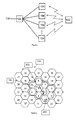
- FIG. 1 is a schematic view showing the data stream between a network component and a mobile station
- FIG. 2 is a schematic view of a wireless telecommunication network
- FIG. 3 is a diagram of set of channel quality information
- FIG. 4 is a diagram of set of channel quality information
- FIG. 5 is a diagram of set of channel quality information
- FIG. 6 is messaging diagram
- FIG. 7 is a block diagram of a wireless telecommunication network.
- FIG. 1 is a schematic view showing a plurality of base stations 104 , a mobile station 100 , a network component 102 and the core network 106 .
- Data can be transmitted from the mobile station to the plurality of base stations 104 or from the base stations 104 to the mobile station 100 according to a coordinated multipoint transmission scheme.
- the data being transmitted from the mobile station 100 to the base stations 104 is then forwarded to the network component 102 , which then transmits the data to the core network 106 .
- the data being sent to the mobile station 100 from the base stations 104 originates from the network component 102 .
- the network component 102 has received this data from the core network 106 .
- FIG. 2 is a schematic view of a wireless telecommunication network 200 comprising a plurality of cells 1 - 37 and a mobile station 100 . Each cell 1 - 37 is served by a corresponding base station 1 - 37 (not depicted)
- the mobile station 100 is first located at position A in cluster 202 .
- Cluster 202 is a CoMP cluster, which is coordinated by the base station of cell 1 .
- the mobile station 100 is located at position B in cell 2 .
- Cell 2 being also in the CoMP cluster 202 and in the CoMP cluster 204 , which comprises the cells 1 , 2 , 3 , 7 , 8 , 9 and 10 , the base station of cell 2 coordinating cluster 204 .
- Cluster 202 consists of cells 1 , 2 , 3 , 4 , 5 , 6 , 7 , the base station of cell 1 coordinating duster 202 .
- a handover is initiated when the mobile station 100 is located at position B because the connection quality of the connection to the base stations of cluster 204 is much better than the connection quality to the base stations of cluster 202 , when the mobile station 100 is located at position B.
- FIG. 3 is a diagram of the set of channel quality information (CQIS) of the mobile station 100 at location A in FIG. 2 .
- the CQIS is an indicator for the channel quality.
- CQIS reports are sent periodically from the mobile station to the serving base station.
- CQIS reports are transmitted from the mobile base station to the base station coordinating the cluster, to which the mobile station is currently connected.
- the CQIS report in FIG. 3 shows the channel state, which corresponds to the channel quality, between the mobile station 100 and the base stations serving cells 1 , 2 , 3 , 4 , 5 , 6 and 7 in FIG. 2 .
- the channel quality of the connection between the mobile station 100 and the base station of cell 1 is the best channel quality in comparison to the other depicted cells because the mobile station 100 is located in cell 1 with a similar distance to each of the other cells of cluster 202 .
- FIG. 4 shows the CQIS of mobile station 100 at location B in FIG. 2 .
- This CQIS report is reported periodically from the mobile station to the first base station serving cell 1 .
- the channel quality between the mobile station 100 and the base station serving cell 2 is better than the channel quality to any other base station. Especially the channel quality between the mobile station 100 and the base station of cells 4 , 5 and 6 is much worse than the channel quality of the connection between the mobile station 100 and base station serving cell number 2 .
- the channel quality of the connection between the mobile station 100 and the base stations of cells 1 , 3 and 7 is in between the other channel qualities.
- the channel quality between the mobile station 100 and base station number 1 is a bit worse than the channel quality between the mobile station 100 and base stations number 3 and 7 .
- FIG. 5 shows a CQIS report transmitted from the mobile station to the second base station number 2 .
- the channel state, which corresponds to the channel quality, between the mobile station 100 and the base station serving cell number 2 is best in comparison to the other base stations belonging to cluster 204 .
- this CQIS reported is requested by the base station serving cell number 1 after having determined that the channel quality between base station number 2 and mobile station 100 is better than the channel quality between base station number 1 and mobile station 100 .
- base station number 1 initiates a handover to base station number 2 .
- the handover procedure can be performed according to common handover procedures.
- FIG. 6 shows a detailed view of the messaging between mobile station 100 , base station number 1 , base station number 2 and the network component 102 .
- base station number 1 receives a CQIS report 600 from mobile station 100 .
- CQIS report 600 is reported periodically to base station number 1 from mobile station 100 .
- base station number 1 requests a CQIS report from base station number 2 with a first signal 602 .
- base station number 2 requests a CQIS report from mobile station 100 .
- Mobile station 100 sends a second CQIS report 606 to base station number 2 .
- the CQIS report 606 comprises the channel states between the mobile station 100 and each base station of cluster 204 , cluster 204 being coordinated by base station number 2 .
- CQIS report 606 is transmitted from base station number 2 to base station number 1 with the CQIS report acknowledgement signal 608 .
- the two received CQIS reports 600 and 606 are compared in base station number 1 during CQIS comparison 610 . This is the location estimation of the mobile station 100 .
- the handover procedure is initiated with a handover request message 612 transmitted from base station number 1 to base station number 2 .
- the handover procedure is indicated to network component 106 from base station number 2 by a handover indication signal 614 .
- the handover indication is acknowledged with a signal 616 and 618 transmitted to the base station number 1 and base station number 2 .
- the data flow is switched 620 .
- the data flow is switched such that the data is not any longer transmitted from the core network 106 to the first group of base stations but to the second group of base stations.
- data transmitted from the mobile station 100 to the core network 106 is received from the second group of base stations instead of the first group of base stations.
- the first group of base stations belongs to cluster 202
- the second group of base stations belongs to cluster 204 .
- the master basestation 1 of CoMP cluster 202 inspects the CQIS of every mobile station 100 which is administered by this master basestation. The time period is preconfigured. Based on the CQIS of the different basestations 2 , 3 , 4 , 5 , 6 and 7 , the master basestation 1 computes a performance index from on the CQIS and a coarse location of the mobile station.
- Basestation 1 which acts as the master basestation of the blue CoMP cluster 202 , inspects the CQIS as shown in FIG. 3 . Based in this CQIS the basestation 1 computes a performance index and a location estimation of the mobile station 100 .
- the result of this location estimation ( FIG. 3 ) indicates that the mobile station is probably located in the centre of cell 1 , because CQI 1 is significantly better than all other and the CQIs of the surrounding cells and the CQIs 2 to 7 are nearly similar.
- the performance index and the location estimation point out, that a hand over is currently not necessary.
- CQIS values change as shown in FIG. 4 .
- Basestation 1 initiates now a report request from basestation 2 which is the master of a neighbour cluster 204 .
- Basestation 2 collects CQIS from its cluster, as shown in FIG. 5 , and reports this information back to basestation 1 by sending a report acknowledge message ( FIG. 6 ).
- Basestation 1 generates a performance index and location estimation based on the received CQIS of cluster 204 ( FIG. 5 ).
- the CQIS of cluster 204 ( FIG. 5 ) gives a significantly better performance index and the location estimation points out that the mobile station is now located in the coverage area of basestation 2 , Basestation 1 decides that the mobile station should be serviced from basestation 2 and sends a handover request message to basestation 2 .
- Basestation 2 sends a handover indication message to the network component 102 which servers both basestations 1 and 2 .
- the backhaul node figures out the data packet number at which a flow switch has to be performed and sends a handover indication message to both basestations 1 and 2 including the packet number.
- the packet number defines the last packet which has to send out to CoMP cluster 202 which is controlled by basestation 1 .
- Packet number n+1 defines the first packet which has to be sent to CoMP cluster 204 which is controlled by basestation 2 .
- FIG. 7 is a block diagram of a wireless telecommunication network 700 comprising a first base station 702 , a plurality of base stations 104 and a plurality of mobile stations 100 .
- the base stations 104 form a cluster coordinated by the first base station 702 .
- the mobile stations 100 are connected to this coordinated multipoint cluster.
- the first base station 702 comprises means 704 for sending and receiving signals to the mobile stations 100 . Also data can be transmitted and received via means 704 .
- Means 704 serve as communication means for communications between the first base station 702 and mobile stations 100 .
- base station 702 comprises means 716 for location estimation of a mobile station 100 .
- base station 702 can transmit and receive signals to and from the network component 102 .
- a processor 710 executes a program 714 in storage 712 , the program causing the processor to perform a method as described above.
Landscapes
- Engineering & Computer Science (AREA)
- Computer Networks & Wireless Communication (AREA)
- Signal Processing (AREA)
- Physics & Mathematics (AREA)
- Electromagnetism (AREA)
- General Physics & Mathematics (AREA)
- Radar, Positioning & Navigation (AREA)
- Remote Sensing (AREA)
- Mobile Radio Communication Systems (AREA)
Abstract
Description
- The invention relates to a method for performing a handover procedure in a wireless coordinated multipoint (CoMP) transmission network.
- In common radio communication systems handover procedures are performed, when a mobile station moves from one cell of the network to another cell of the network. The connection of a mobile station is always controlled by only one base station. The mobile station receives connection data from this base station.
- In coordinated multipoint networks multiple base stations send information in a coordinated manner to the mobile station. Common handover mechanisms are not applicable for CoMP networks.
- 3GPP TS 36.300 version 8.9.0
Release 8 discloses an overview and overall description of the E-UTRAN radio interface protocol architecture. The Intra-E-UTRAN-Access Mobility Support for mobile stations handles all necessary steps for relocation/handover procedures, like processes that precede the final handover decision on the source network side (control and evaluation of mobile station and base station measurements taking into account certain mobile station specific are restrictions), preparation of resources on the target network side, commanding the mobile station to the new radio resource and finally releasing resources on the (old) source network side. It contains mechanisms to transfer context data between evolved nodes, and to update node relations on C-plane and U-plane. - WO 00/67512A1 discloses a method for performing a handover procedure for a mobile station, said method comprising the steps of processing location information related to the mobile stations and position information related to base transceiver station, and deciding on the basis of the result of said processing, whether a first handover condition is fulfilled.
- The invention provides a method for performing a handover procedure in a wireless coordinated multipoint (CoMP) transmission network of a mobile station from a first base station to a second base station. The first base station coordinates a first group of base stations. The first base station is a member of the first group. The second base station coordinates a second group of base stations. The second base station is a member of the second group. A network component is adapted to transmit data to the first base station and the first group of base stations and/or to the second base station and the second group of base stations.
- In other words, a data stream meant to be transmitted to the mobile station is transmitted from the network component to the first group of base stations and then forwarded to the mobile station. When a handover of the mobile station from the first base station to the second base station shall be performed the data which shall be transmitted to the mobile station must be directed to the second base station and the second group of base stations instead of the first group in the first group of base stations. The same applies for data being sent from the mobile station to a base station of the first group, the data being meant to be sent to another component in the network, for example another mobile station or a gateway to another network. The data being transmitted from the mobile station to the first group of base stations is first transmitted from the first group of base stations to the network component which then forwards the data to other network means.
- Both data streams, the first one from the network component to the mobile station and the second one from the mobile station to the network component, must be redirected in case of a handover procedure. Therefore, the location of the mobile station is estimated. Preferably, the location estimation is based on channel quality information. Most preferably, the first base station has requested channel quality information from the second base station and the first base station has received channel quality information from the second base station. Channel quality information of the channels between the mobile station and each base station of the first group of base stations are transmitted periodically from the mobile station to the first base station or on request of the first base station.
- After location estimation a first signal is sent to the second base station, the first signal being indicative of requesting the handover procedure. Preferably, the first signal is transmitted from the first base station to the second base station.
- A second signal is sent to the network component, preferably from the second base station. The second signal is indicative of initiating the handover procedure. Then, the data stream from the network component is directed to the second base station and the second group. Then, the connection of the mobile station to the network is controlled by the second base station and every base station of the second group is used for transmitting and receiving data to and from the mobile station according to a coordinated multipoint transmission scheme.
- According to embodiments of the invention the location estimation is performed based on channel quality information, the channel quality information being information of connections between the mobile station and the first group and/or information of connections between the mobile station and the second group.
- According to embodiments of the invention a fourth signal is sent to the second base station before location estimation. The fourth signal is indicative of requesting a channel quality report. Preferably the fourth signal is transmitted from the first base station to the second base station. A channel quality report always comprises the quality of the channel of the connection between a mobile station and at least one base station. In a coordinated multipoint transmission network one channel quality report always comprises the channel quality of the connection between the mobile station and each base station of one of the first and the second group. Thus, a channel quality report being transmitted from the mobile station to the first base station comprises the channel quality of the connections between the mobile station and each base station of the first group. A channel quality report be ing sent from the mobile station to the second base station comprises the channel quality of the connection of the mobile station to each base station of the second group.
- By knowing the channel quality of the connections of the mobile station to each base station of the first and of the second group the location of the mobile station can be estimated. Location estimation is also feasible based only on the channel quality of the connections of one group. Preferably this is the first group. Alternatively it can also be the channel quality of only the second group.
- According to embodiments of the invention first channel quality information is transmitted from the mobile station to the first base station and second channel quality information is transmitted from the second base station to the first base station. Preferably, the second channel quality information comprises information about the channel quality of the connection between the mobile station and the second group of base stations.
- According to embodiments of the invention the first channel quality information comprises information about a first connection quality between the mobile station and the first base station. The second channel quality information comprises information about a second connection quality between the base station and the second base station.
- According to embodiments of the invention the handover procedure is initiated when the second connection quality of the connection between the mobile station and the second base station is above a first threshold.
- According to embodiments of the invention the handover procedure is initiated when the first connection quality of the connection between the mobile station and the first base station is below a second threshold.
- According to embodiments of the invention the first base station is also a member of the second group and the second base station is also a member of the first group.
- According to embodiments of the invention the method comprises a further step of sending a third signal from the network component to the first base station and a fourth signal from the network component to the second base station. The third and the fourth signal are indicative of initiating the handover procedure.
- In another aspect the invention relates to a computer readable storage medium containing instructions that when executed by a base station cause the base station to perform a method according to embodiments of the invention.
- In yet another aspect the invention relates to a base station apparatus, which comprises means for estimating a location of the mobile station, means for sending a first signal to the second base station, means for sending a second signal to the network component and means for transmitting data to the second base station.
- In yet another aspect the invention relates to a telecommunication system comprising a plurality of base stations as described above.
- In the following preferred embodiments of the invention will be described, by way of example only, and with reference to the drawings in which:
-
FIG. 1 is a schematic view showing the data stream between a network component and a mobile station; -
FIG. 2 is a schematic view of a wireless telecommunication network; -
FIG. 3 is a diagram of set of channel quality information; -
FIG. 4 is a diagram of set of channel quality information; -
FIG. 5 is a diagram of set of channel quality information; -
FIG. 6 is messaging diagram; and -
FIG. 7 is a block diagram of a wireless telecommunication network. - Like numbered elements in these Figs. are either identical elements or perform the same function. Elements which have been discussed previously will not necessarily be discussed in later Figs. if the function is identical.
-
FIG. 1 is a schematic view showing a plurality ofbase stations 104, amobile station 100, anetwork component 102 and thecore network 106. - Data can be transmitted from the mobile station to the plurality of
base stations 104 or from thebase stations 104 to themobile station 100 according to a coordinated multipoint transmission scheme. The data being transmitted from themobile station 100 to thebase stations 104 is then forwarded to thenetwork component 102, which then transmits the data to thecore network 106. In the other direction, the data being sent to themobile station 100 from thebase stations 104 originates from thenetwork component 102. Thenetwork component 102 has received this data from thecore network 106. -
FIG. 2 is a schematic view of awireless telecommunication network 200 comprising a plurality of cells 1-37 and amobile station 100. Each cell 1-37 is served by a corresponding base station 1-37 (not depicted) - The
mobile station 100 is first located at position A incluster 202.Cluster 202 is a CoMP cluster, which is coordinated by the base station ofcell 1. At a second time point themobile station 100 is located at position B incell 2.Cell 2 being also in theCoMP cluster 202 and in theCoMP cluster 204, which comprises thecells cell 2 coordinatingcluster 204.Cluster 202 consists ofcells cell 1coordinating duster 202. - A handover is initiated when the
mobile station 100 is located at position B because the connection quality of the connection to the base stations ofcluster 204 is much better than the connection quality to the base stations ofcluster 202, when themobile station 100 is located at position B. -
FIG. 3 is a diagram of the set of channel quality information (CQIS) of themobile station 100 at location A inFIG. 2 . The CQIS is an indicator for the channel quality. CQIS reports are sent periodically from the mobile station to the serving base station. In CoMP networks CQIS reports are transmitted from the mobile base station to the base station coordinating the cluster, to which the mobile station is currently connected. - The CQIS report in
FIG. 3 shows the channel state, which corresponds to the channel quality, between themobile station 100 and the basestations serving cells FIG. 2 . At location A the channel quality of the connection between themobile station 100 and the base station ofcell 1 is the best channel quality in comparison to the other depicted cells because themobile station 100 is located incell 1 with a similar distance to each of the other cells ofcluster 202. -
FIG. 4 shows the CQIS ofmobile station 100 at location B inFIG. 2 . This CQIS report is reported periodically from the mobile station to the first basestation serving cell 1. The channel quality between themobile station 100 and the basestation serving cell 2 is better than the channel quality to any other base station. Especially the channel quality between themobile station 100 and the base station ofcells mobile station 100 and base station servingcell number 2. The channel quality of the connection between themobile station 100 and the base stations ofcells mobile station 100 andbase station number 1 is a bit worse than the channel quality between themobile station 100 andbase stations number -
FIG. 5 shows a CQIS report transmitted from the mobile station to the secondbase station number 2. The channel state, which corresponds to the channel quality, between themobile station 100 and the base station servingcell number 2 is best in comparison to the other base stations belonging to cluster 204. Preferably, this CQIS reported is requested by the base station servingcell number 1 after having determined that the channel quality betweenbase station number 2 andmobile station 100 is better than the channel quality betweenbase station number 1 andmobile station 100. - By knowing the diagrams of
FIG. 4 andFIG. 5 ,base station number 1 initiates a handover tobase station number 2. This means, the data flow frommobile station 100 to thecore network 106 and vice versa has to be directed to thecluster 204 coordinated bybase station number 2. The handover procedure can be performed according to common handover procedures. -
FIG. 6 shows a detailed view of the messaging betweenmobile station 100,base station number 1,base station number 2 and thenetwork component 102. First,base station number 1 receives aCQIS report 600 frommobile station 100.CQIS report 600 is reported periodically tobase station number 1 frommobile station 100. Then,base station number 1 requests a CQIS report frombase station number 2 with afirst signal 602. Then, with asecond signal 604,base station number 2 requests a CQIS report frommobile station 100.Mobile station 100 sends asecond CQIS report 606 tobase station number 2. TheCQIS report 606 comprises the channel states between themobile station 100 and each base station ofcluster 204,cluster 204 being coordinated bybase station number 2. Then,CQIS report 606 is transmitted frombase station number 2 tobase station number 1 with the CQISreport acknowledgement signal 608. - The two received CQIS reports 600 and 606 are compared in
base station number 1 duringCQIS comparison 610. This is the location estimation of themobile station 100. AfterCQIS comparison 610 the handover procedure is initiated with ahandover request message 612 transmitted frombase station number 1 tobase station number 2. The handover procedure is indicated tonetwork component 106 frombase station number 2 by ahandover indication signal 614. The handover indication is acknowledged with asignal base station number 1 andbase station number 2. Afterwards the data flow is switched 620. The data flow is switched such that the data is not any longer transmitted from thecore network 106 to the first group of base stations but to the second group of base stations. In the other direction data transmitted from themobile station 100 to thecore network 106 is received from the second group of base stations instead of the first group of base stations. The first group of base stations belongs to cluster 202, while the second group of base stations belongs to cluster 204. - Periodically the
master basestation 1 ofCoMP cluster 202 inspects the CQIS of everymobile station 100 which is administered by this master basestation. The time period is preconfigured. Based on the CQIS of thedifferent basestations master basestation 1 computes a performance index from on the CQIS and a coarse location of the mobile station. -
Basestation 1, which acts as the master basestation of theblue CoMP cluster 202, inspects the CQIS as shown inFIG. 3 . Based in this CQIS thebasestation 1 computes a performance index and a location estimation of themobile station 100. The result of this location estimation (FIG. 3 ) indicates that the mobile station is probably located in the centre ofcell 1, becauseCQI 1 is significantly better than all other and the CQIs of the surrounding cells and theCQIs 2 to 7 are nearly similar. The performance index and the location estimation point out, that a hand over is currently not necessary. - When the mobile station changes its location from A to B, CQIS values change as shown in
FIG. 4 . By inspecting theseCQIS basestation 1 assumes that the mobile station has changed its location and is now located in the coverage area ofbasestation 2, because CQIs ofbasestation 2 is the best channel condition, while Cats of the opposite locatedbasestation Basestation 1 initiates now a report request frombasestation 2 which is the master of aneighbour cluster 204.Basestation 2 collects CQIS from its cluster, as shown inFIG. 5 , and reports this information back tobasestation 1 by sending a report acknowledge message (FIG. 6 ).Basestation 1 generates a performance index and location estimation based on the received CQIS of cluster 204 (FIG. 5 ). The CQIS of cluster 204 (FIG. 5 ) gives a significantly better performance index and the location estimation points out that the mobile station is now located in the coverage area ofbasestation 2,Basestation 1 decides that the mobile station should be serviced frombasestation 2 and sends a handover request message tobasestation 2. -
Basestation 2 sends a handover indication message to thenetwork component 102 which servers bothbasestations basestations CoMP cluster 202 which is controlled bybasestation 1. Packet number n+1 defines the first packet which has to be sent toCoMP cluster 204 which is controlled bybasestation 2. -
FIG. 7 is a block diagram of awireless telecommunication network 700 comprising afirst base station 702, a plurality ofbase stations 104 and a plurality ofmobile stations 100. Thebase stations 104 form a cluster coordinated by thefirst base station 702. Themobile stations 100 are connected to this coordinated multipoint cluster. Thefirst base station 702 comprisesmeans 704 for sending and receiving signals to themobile stations 100. Also data can be transmitted and received viameans 704.Means 704 serve as communication means for communications between thefirst base station 702 andmobile stations 100. - Further,
base station 702 comprisesmeans 716 for location estimation of amobile station 100. With means 718base station 702 can transmit and receive signals to and from thenetwork component 102. - Preferably a
processor 710 executes aprogram 714 instorage 712, the program causing the processor to perform a method as described above. -
-
- 100 mobile station
- 102 network component
- 104 base station
- 106 core network
- 200 wireless telecommunication network
- 202 GoMP cluster
- 204 GoMP cluster
- 600 GQIS report
- 602 signal
- 604 signal
- 606 CQIS report
- 608 CQIS report ack
- 610 CQIS comparison
- 612 handover request
- 614 handover indication
- 616 handover indication ack
- 618 handover indication ack
- 620 flow switch
- 700 wireless telecommunication network
- 702 base station
- 704 communication means
- 710 processor
- 712 data storage
- 714 program
- 716 location estimation means
- 718 communication means
Claims (12)
Applications Claiming Priority (4)
| Application Number | Priority Date | Filing Date | Title |
|---|---|---|---|
| EP09290959A EP2337400B1 (en) | 2009-12-17 | 2009-12-17 | Handover procedure in a coordinated multipoint (CoMP) transmission network |
| EP09290959 | 2009-12-17 | ||
| EP09290959.7 | 2009-12-17 | ||
| PCT/EP2010/068295 WO2011073011A1 (en) | 2009-12-17 | 2010-11-26 | Handover procedure in a coordinated multipoint (comp) transmission network |
Publications (2)
| Publication Number | Publication Date |
|---|---|
| US20120252462A1 true US20120252462A1 (en) | 2012-10-04 |
| US8738001B2 US8738001B2 (en) | 2014-05-27 |
Family
ID=42154331
Family Applications (1)
| Application Number | Title | Priority Date | Filing Date |
|---|---|---|---|
| US13/516,342 Active US8738001B2 (en) | 2009-12-17 | 2010-11-26 | Handover procedure in a coordinated multipoint (CoMP) transmission network |
Country Status (7)
| Country | Link |
|---|---|
| US (1) | US8738001B2 (en) |
| EP (1) | EP2337400B1 (en) |
| JP (1) | JP5657022B2 (en) |
| KR (1) | KR101355012B1 (en) |
| CN (1) | CN102668636B (en) |
| AT (1) | ATE554617T1 (en) |
| WO (1) | WO2011073011A1 (en) |
Cited By (13)
| Publication number | Priority date | Publication date | Assignee | Title |
|---|---|---|---|---|
| US20130028120A1 (en) * | 2011-07-28 | 2013-01-31 | Futurewei Technologies, Inc. | System and Method for Measuring and Reporting Uplink Channel Condition |
| US20130170474A1 (en) * | 2012-01-04 | 2013-07-04 | Futurewei Technologies, Inc. | System and Method for Primary Point Handovers |
| CN104301883A (en) * | 2013-07-16 | 2015-01-21 | 电信科学技术研究院 | Coordinated multiple-point transmission control method and device for use in cell handover process |
| US20150215162A1 (en) * | 2011-12-16 | 2015-07-30 | Futurewei Technologies, Inc. | System and Method of Radio Bearer Management for Multiple Point Transmission |
| US20160248483A1 (en) * | 2011-12-02 | 2016-08-25 | Apple Inc. | Methods for Operating Wireless Electronic Devices in Coordinated Multipoint Transmission Networks |
| US9467494B1 (en) * | 2011-12-30 | 2016-10-11 | Rupaka Mahalingaiah | Method and apparatus for enabling mobile cluster computing |
| US20170142621A1 (en) * | 2015-06-01 | 2017-05-18 | Telefonaktiebolaget Lm Ericsson (Publ) | Methods used in cluster manager, radio node and control node, and associated devices |
| US20170164252A1 (en) * | 2015-12-04 | 2017-06-08 | Wipro Limited | Methods and Systems for Coordination Multi Point Set Determination for a Wireless Network |
| US20180019829A1 (en) * | 2016-07-15 | 2018-01-18 | Fujitsu Limited | Controller, communication system, and radio control method |
| US10237759B1 (en) * | 2017-03-29 | 2019-03-19 | Sprint Spectrum L.P. | Coordinated multipoint set selection based on donor status |
| US10243638B2 (en) * | 2016-10-04 | 2019-03-26 | At&T Intellectual Property I, L.P. | Forward error correction code selection in wireless systems |
| US10270559B2 (en) | 2016-10-04 | 2019-04-23 | At&T Intellectual Property I, L.P. | Single encoder and decoder for forward error correction coding |
| US10271257B2 (en) | 2016-03-29 | 2019-04-23 | Wipro Limited | Methods and systems for coordinated multipoint (CoMP) enabled handover in wireless communication networks |
Families Citing this family (7)
| Publication number | Priority date | Publication date | Assignee | Title |
|---|---|---|---|---|
| EP2795960B1 (en) * | 2011-12-21 | 2020-02-26 | Nokia Solutions and Networks Oy | Providing mobility control for local area networks |
| CN103200629B (en) | 2012-01-10 | 2016-08-03 | 华为技术有限公司 | Base station switch method, X2 interface method for building up, base station, user terminal and system |
| WO2013141508A1 (en) * | 2012-03-19 | 2013-09-26 | 엘지전자 주식회사 | Method for performing high-speed handover in base station cooperative wireless communication system, and device for same |
| JP5759417B2 (en) * | 2012-05-16 | 2015-08-05 | 日本電信電話株式会社 | Wireless communication system and connection switching method |
| US9439097B2 (en) * | 2014-02-10 | 2016-09-06 | Alcatel Lucent | Selective signaling information sharing for CoMP enhancement |
| MX2018006467A (en) | 2014-08-07 | 2022-04-25 | One Media Llc | Dynamic configuration of a flexible orthogonal frequency division multiplexing phy transport data frame. |
| KR20170051437A (en) | 2014-08-07 | 2017-05-11 | 코히어런트 로직스, 인코포레이티드 | Multi-partition radio frames |
Citations (2)
| Publication number | Priority date | Publication date | Assignee | Title |
|---|---|---|---|---|
| US20090239536A1 (en) * | 2005-12-09 | 2009-09-24 | Anna Fallgren | Network Evaluated Hard Hardover Using Predictions |
| US8498267B2 (en) * | 2009-05-01 | 2013-07-30 | At&T Mobility Ii Llc | Access control for macrocell to femtocell handover |
Family Cites Families (4)
| Publication number | Priority date | Publication date | Assignee | Title |
|---|---|---|---|---|
| US6321090B1 (en) * | 1998-11-06 | 2001-11-20 | Samir S. Soliman | Mobile communication system with position detection to facilitate hard handoff |
| WO2000067512A1 (en) * | 1999-04-30 | 2000-11-09 | Nokia Networks Oy | Method and device for performing handover using location information |
| US20110044290A1 (en) * | 2006-04-28 | 2011-02-24 | Panasonic Corporation | Communication terminal apparatus and handover method |
| CN101483873B (en) * | 2008-12-26 | 2010-09-08 | 西安电子科技大学 | Uplink multipoint collaboration implementing method combining inter-cell interference coordination |
-
2009
- 2009-12-17 AT AT09290959T patent/ATE554617T1/en active
- 2009-12-17 EP EP09290959A patent/EP2337400B1/en not_active Not-in-force
-
2010
- 2010-11-26 JP JP2012543579A patent/JP5657022B2/en not_active Expired - Fee Related
- 2010-11-26 KR KR1020127018107A patent/KR101355012B1/en active IP Right Grant
- 2010-11-26 CN CN201080059361.3A patent/CN102668636B/en not_active Expired - Fee Related
- 2010-11-26 WO PCT/EP2010/068295 patent/WO2011073011A1/en active Application Filing
- 2010-11-26 US US13/516,342 patent/US8738001B2/en active Active
Patent Citations (2)
| Publication number | Priority date | Publication date | Assignee | Title |
|---|---|---|---|---|
| US20090239536A1 (en) * | 2005-12-09 | 2009-09-24 | Anna Fallgren | Network Evaluated Hard Hardover Using Predictions |
| US8498267B2 (en) * | 2009-05-01 | 2013-07-30 | At&T Mobility Ii Llc | Access control for macrocell to femtocell handover |
Cited By (26)
| Publication number | Priority date | Publication date | Assignee | Title |
|---|---|---|---|---|
| US10560860B2 (en) | 2011-07-28 | 2020-02-11 | Futurewei Technologies, Inc. | System and method for measuring and reporting uplink channel condition |
| US20130028120A1 (en) * | 2011-07-28 | 2013-01-31 | Futurewei Technologies, Inc. | System and Method for Measuring and Reporting Uplink Channel Condition |
| US9848349B2 (en) * | 2011-07-28 | 2017-12-19 | Futurewei Technologies, Inc. | System and method for measuring and reporting uplink channel condition |
| US20160248483A1 (en) * | 2011-12-02 | 2016-08-25 | Apple Inc. | Methods for Operating Wireless Electronic Devices in Coordinated Multipoint Transmission Networks |
| US10284263B2 (en) * | 2011-12-02 | 2019-05-07 | Apple Inc. | Methods for operating wireless electronic devices in coordinated multipoint transmission networks |
| US10680881B2 (en) * | 2011-12-16 | 2020-06-09 | Futurewei Technologies, Inc. | System and method of radio bearer management for multiple point transmission |
| US20150215162A1 (en) * | 2011-12-16 | 2015-07-30 | Futurewei Technologies, Inc. | System and Method of Radio Bearer Management for Multiple Point Transmission |
| US9467494B1 (en) * | 2011-12-30 | 2016-10-11 | Rupaka Mahalingaiah | Method and apparatus for enabling mobile cluster computing |
| US10212254B1 (en) | 2011-12-30 | 2019-02-19 | Rupaka Mahalingaiah | Method and apparatus for enabling mobile cluster computing |
| US8724590B2 (en) * | 2012-01-04 | 2014-05-13 | Futurewei Technologies, Inc. | System and method for primary point handovers |
| USRE47613E1 (en) * | 2012-01-04 | 2019-09-17 | Futurewei Technologies, Inc. | System and method for primary point handovers |
| US20130170474A1 (en) * | 2012-01-04 | 2013-07-04 | Futurewei Technologies, Inc. | System and Method for Primary Point Handovers |
| CN104301883B (en) * | 2013-07-16 | 2018-01-16 | 电信科学技术研究院 | A kind of cooperative multipoint transmission control method and device in cell switch process |
| CN104301883A (en) * | 2013-07-16 | 2015-01-21 | 电信科学技术研究院 | Coordinated multiple-point transmission control method and device for use in cell handover process |
| US20170142621A1 (en) * | 2015-06-01 | 2017-05-18 | Telefonaktiebolaget Lm Ericsson (Publ) | Methods used in cluster manager, radio node and control node, and associated devices |
| US9848361B2 (en) * | 2015-06-01 | 2017-12-19 | Telefonaktiebolaget Lm Ericsson (Publ) | Methods used in cluster manager, radio node and control node, and associated devices |
| US20170164252A1 (en) * | 2015-12-04 | 2017-06-08 | Wipro Limited | Methods and Systems for Coordination Multi Point Set Determination for a Wireless Network |
| US10271257B2 (en) | 2016-03-29 | 2019-04-23 | Wipro Limited | Methods and systems for coordinated multipoint (CoMP) enabled handover in wireless communication networks |
| US10056994B2 (en) * | 2016-07-15 | 2018-08-21 | Fujitsu Limited | Controller, communication system, and radio control method |
| US20180019829A1 (en) * | 2016-07-15 | 2018-01-18 | Fujitsu Limited | Controller, communication system, and radio control method |
| US10270559B2 (en) | 2016-10-04 | 2019-04-23 | At&T Intellectual Property I, L.P. | Single encoder and decoder for forward error correction coding |
| US10243638B2 (en) * | 2016-10-04 | 2019-03-26 | At&T Intellectual Property I, L.P. | Forward error correction code selection in wireless systems |
| US10666339B2 (en) | 2016-10-04 | 2020-05-26 | At&T Intellectual Property I, L.P. | Forward error correction code selection in wireless systems |
| US10700813B2 (en) | 2016-10-04 | 2020-06-30 | At&T Intellectual Property I, L.P. | Single encoder and decoder for forward error correction coding |
| US10979124B2 (en) | 2016-10-04 | 2021-04-13 | At&T Intellectual Property I, L.P. | Forward error correction code selection in wireless systems |
| US10237759B1 (en) * | 2017-03-29 | 2019-03-19 | Sprint Spectrum L.P. | Coordinated multipoint set selection based on donor status |
Also Published As
| Publication number | Publication date |
|---|---|
| CN102668636B (en) | 2016-04-20 |
| CN102668636A (en) | 2012-09-12 |
| KR101355012B1 (en) | 2014-01-24 |
| US8738001B2 (en) | 2014-05-27 |
| JP2013514693A (en) | 2013-04-25 |
| ATE554617T1 (en) | 2012-05-15 |
| KR20120112540A (en) | 2012-10-11 |
| WO2011073011A1 (en) | 2011-06-23 |
| EP2337400A1 (en) | 2011-06-22 |
| JP5657022B2 (en) | 2015-01-21 |
| EP2337400B1 (en) | 2012-04-18 |
Similar Documents
| Publication | Publication Date | Title |
|---|---|---|
| US8738001B2 (en) | Handover procedure in a coordinated multipoint (CoMP) transmission network | |
| US8548476B2 (en) | Method of managing X2 interface, handover method, interference coordination method and apparatus | |
| CN105848222B (en) | Method and base station equipment for switching | |
| US8442007B2 (en) | Bearer establishing method and system based on handover | |
| EP1946601B1 (en) | Select diversity for radio communications | |
| EP2914035B1 (en) | Base station handover method and system for communications system | |
| US8787317B2 (en) | Wireless handover optimization | |
| US9510259B2 (en) | Methods and arrangement for handling a data transferral in a cellular network | |
| CN104937967B (en) | Method and apparatus for cooperative communication in wireless communication system | |
| US20090156212A1 (en) | Data transfer method and base station | |
| US9144000B2 (en) | Cell specifying method, base station, and mobile station | |
| CN104956731A (en) | Method and apparatus for controlling mobility for a cell having a small cell service area in a mobile communication system | |
| US20140200011A1 (en) | LTE/HSDPA Carrier Aggregation | |
| US7489929B2 (en) | Hard handoff procedure for dedicated and high speed shared channels | |
| KR20100070688A (en) | Method of optimal handover based on wireless link quality of user equipment | |
| CN109219978A (en) | Cut-in method, user equipment, control equipment and communication system | |
| EP1411739A1 (en) | A method of selecting cells of base stations for soft-handover connection, and a network for mobile telecommunications | |
| US10813023B2 (en) | Handover between a source access node and a target access node using a control device | |
| CN114390609B (en) | Data transmission method, device and equipment | |
| WO2017026444A1 (en) | Wireless terminal and base station | |
| US20240121683A1 (en) | Upf based transmision of user data for selective activation to selective activation candidate nodes |
Legal Events
| Date | Code | Title | Description |
|---|---|---|---|
| AS | Assignment |
Owner name: ALCATEL LUCENT, FRANCE Free format text: ASSIGNMENT OF ASSIGNORS INTEREST;ASSIGNOR:FAHLDIECK, TORSTEN;REEL/FRAME:028383/0066 Effective date: 20101202 |
|
| AS | Assignment |
Owner name: CREDIT SUISSE AG, NEW YORK Free format text: SECURITY AGREEMENT;ASSIGNOR:LUCENT, ALCATEL;REEL/FRAME:029821/0001 Effective date: 20130130 Owner name: CREDIT SUISSE AG, NEW YORK Free format text: SECURITY AGREEMENT;ASSIGNOR:ALCATEL LUCENT;REEL/FRAME:029821/0001 Effective date: 20130130 |
|
| FEPP | Fee payment procedure |
Free format text: PAYOR NUMBER ASSIGNED (ORIGINAL EVENT CODE: ASPN); ENTITY STATUS OF PATENT OWNER: LARGE ENTITY |
|
| STCF | Information on status: patent grant |
Free format text: PATENTED CASE |
|
| AS | Assignment |
Owner name: ALCATEL LUCENT, FRANCE Free format text: RELEASE BY SECURED PARTY;ASSIGNOR:CREDIT SUISSE AG;REEL/FRAME:033868/0555 Effective date: 20140819 |
|
| MAFP | Maintenance fee payment |
Free format text: PAYMENT OF MAINTENANCE FEE, 4TH YEAR, LARGE ENTITY (ORIGINAL EVENT CODE: M1551) Year of fee payment: 4 |
|
| MAFP | Maintenance fee payment |
Free format text: PAYMENT OF MAINTENANCE FEE, 8TH YEAR, LARGE ENTITY (ORIGINAL EVENT CODE: M1552); ENTITY STATUS OF PATENT OWNER: LARGE ENTITY Year of fee payment: 8 |