US20120172655A1 - Impeller housing for percutaneous heart pump - Google Patents
Impeller housing for percutaneous heart pump Download PDFInfo
- Publication number
- US20120172655A1 US20120172655A1 US13/343,617 US201213343617A US2012172655A1 US 20120172655 A1 US20120172655 A1 US 20120172655A1 US 201213343617 A US201213343617 A US 201213343617A US 2012172655 A1 US2012172655 A1 US 2012172655A1
- Authority
- US
- United States
- Prior art keywords
- impeller
- housing
- catheter assembly
- distal
- proximal
- Prior art date
- Legal status (The legal status is an assumption and is not a legal conclusion. Google has not performed a legal analysis and makes no representation as to the accuracy of the status listed.)
- Granted
Links
- 210000002216 heart Anatomy 0.000 title claims abstract description 95
- 239000011248 coating agent Substances 0.000 claims description 41
- 238000000576 coating method Methods 0.000 claims description 41
- 239000000463 material Substances 0.000 claims description 30
- 210000004369 blood Anatomy 0.000 claims description 29
- 239000008280 blood Substances 0.000 claims description 29
- 230000001965 increasing effect Effects 0.000 claims description 22
- 239000012530 fluid Substances 0.000 claims description 19
- 210000003484 anatomy Anatomy 0.000 claims description 18
- 230000000916 dilatatory effect Effects 0.000 claims description 17
- 238000005452 bending Methods 0.000 claims description 11
- 238000003780 insertion Methods 0.000 claims description 9
- 230000037431 insertion Effects 0.000 claims description 9
- 230000003247 decreasing effect Effects 0.000 claims description 6
- 210000005242 cardiac chamber Anatomy 0.000 claims description 5
- 230000002093 peripheral effect Effects 0.000 claims description 5
- 230000004888 barrier function Effects 0.000 claims description 3
- 230000000694 effects Effects 0.000 claims description 3
- 238000011144 upstream manufacturing Methods 0.000 claims description 3
- 238000000034 method Methods 0.000 description 30
- 239000000306 component Substances 0.000 description 22
- 230000008901 benefit Effects 0.000 description 15
- 230000007704 transition Effects 0.000 description 14
- 230000008878 coupling Effects 0.000 description 10
- 238000010168 coupling process Methods 0.000 description 10
- 238000005859 coupling reaction Methods 0.000 description 10
- 210000001765 aortic valve Anatomy 0.000 description 9
- 238000001802 infusion Methods 0.000 description 9
- 210000005240 left ventricle Anatomy 0.000 description 9
- 239000000853 adhesive Substances 0.000 description 8
- 230000001070 adhesive effect Effects 0.000 description 8
- 230000008859 change Effects 0.000 description 8
- 230000002708 enhancing effect Effects 0.000 description 8
- 230000004044 response Effects 0.000 description 8
- 239000012781 shape memory material Substances 0.000 description 8
- 230000002861 ventricular Effects 0.000 description 7
- 238000006073 displacement reaction Methods 0.000 description 6
- 230000003993 interaction Effects 0.000 description 6
- 238000007493 shaping process Methods 0.000 description 6
- 210000005166 vasculature Anatomy 0.000 description 6
- 206010018910 Haemolysis Diseases 0.000 description 5
- 210000000709 aorta Anatomy 0.000 description 5
- 230000017531 blood circulation Effects 0.000 description 5
- 230000008588 hemolysis Effects 0.000 description 5
- 238000005086 pumping Methods 0.000 description 5
- 230000003044 adaptive effect Effects 0.000 description 4
- 210000004027 cell Anatomy 0.000 description 4
- 238000004891 communication Methods 0.000 description 4
- 230000006378 damage Effects 0.000 description 4
- 210000003743 erythrocyte Anatomy 0.000 description 4
- 208000014674 injury Diseases 0.000 description 4
- 229910001000 nickel titanium Inorganic materials 0.000 description 4
- 206010007556 Cardiac failure acute Diseases 0.000 description 3
- 238000013459 approach Methods 0.000 description 3
- 230000000712 assembly Effects 0.000 description 3
- 238000000429 assembly Methods 0.000 description 3
- 239000012503 blood component Substances 0.000 description 3
- 230000000747 cardiac effect Effects 0.000 description 3
- 230000001276 controlling effect Effects 0.000 description 3
- 238000013461 design Methods 0.000 description 3
- 238000004519 manufacturing process Methods 0.000 description 3
- 238000012544 monitoring process Methods 0.000 description 3
- HLXZNVUGXRDIFK-UHFFFAOYSA-N nickel titanium Chemical compound [Ti].[Ti].[Ti].[Ti].[Ti].[Ti].[Ti].[Ti].[Ti].[Ti].[Ti].[Ni].[Ni].[Ni].[Ni].[Ni].[Ni].[Ni].[Ni].[Ni].[Ni].[Ni].[Ni].[Ni].[Ni] HLXZNVUGXRDIFK-UHFFFAOYSA-N 0.000 description 3
- 210000001147 pulmonary artery Anatomy 0.000 description 3
- 230000008733 trauma Effects 0.000 description 3
- 230000000472 traumatic effect Effects 0.000 description 3
- 208000006117 ST-elevation myocardial infarction Diseases 0.000 description 2
- FAPWRFPIFSIZLT-UHFFFAOYSA-M Sodium chloride Chemical compound [Na+].[Cl-] FAPWRFPIFSIZLT-UHFFFAOYSA-M 0.000 description 2
- 208000007536 Thrombosis Diseases 0.000 description 2
- 230000002411 adverse Effects 0.000 description 2
- 230000003466 anti-cipated effect Effects 0.000 description 2
- 230000015572 biosynthetic process Effects 0.000 description 2
- 230000036772 blood pressure Effects 0.000 description 2
- 238000010276 construction Methods 0.000 description 2
- -1 copper-zinc-aluminum Chemical compound 0.000 description 2
- 230000007423 decrease Effects 0.000 description 2
- 229940079593 drug Drugs 0.000 description 2
- 239000003814 drug Substances 0.000 description 2
- 230000006870 function Effects 0.000 description 2
- 238000002955 isolation Methods 0.000 description 2
- 238000005304 joining Methods 0.000 description 2
- 230000013011 mating Effects 0.000 description 2
- 238000012986 modification Methods 0.000 description 2
- 230000004048 modification Effects 0.000 description 2
- 208000010125 myocardial infarction Diseases 0.000 description 2
- 210000004165 myocardium Anatomy 0.000 description 2
- 238000011176 pooling Methods 0.000 description 2
- 230000008569 process Effects 0.000 description 2
- 210000005241 right ventricle Anatomy 0.000 description 2
- 238000000926 separation method Methods 0.000 description 2
- 239000011780 sodium chloride Substances 0.000 description 2
- 210000001519 tissue Anatomy 0.000 description 2
- 230000002792 vascular Effects 0.000 description 2
- WQZGKKKJIJFFOK-GASJEMHNSA-N Glucose Natural products OC[C@H]1OC(O)[C@H](O)[C@@H](O)[C@@H]1O WQZGKKKJIJFFOK-GASJEMHNSA-N 0.000 description 1
- 208000010496 Heart Arrest Diseases 0.000 description 1
- 206010019280 Heart failures Diseases 0.000 description 1
- 208000027418 Wounds and injury Diseases 0.000 description 1
- HZEWFHLRYVTOIW-UHFFFAOYSA-N [Ti].[Ni] Chemical compound [Ti].[Ni] HZEWFHLRYVTOIW-UHFFFAOYSA-N 0.000 description 1
- 230000001154 acute effect Effects 0.000 description 1
- 239000012790 adhesive layer Substances 0.000 description 1
- 210000002376 aorta thoracic Anatomy 0.000 description 1
- 206010003119 arrhythmia Diseases 0.000 description 1
- 238000010009 beating Methods 0.000 description 1
- 230000009286 beneficial effect Effects 0.000 description 1
- 239000013060 biological fluid Substances 0.000 description 1
- 210000000601 blood cell Anatomy 0.000 description 1
- 210000004204 blood vessel Anatomy 0.000 description 1
- WJCRZORJJRCRAW-UHFFFAOYSA-N cadmium gold Chemical compound [Cd].[Au] WJCRZORJJRCRAW-UHFFFAOYSA-N 0.000 description 1
- 206010007625 cardiogenic shock Diseases 0.000 description 1
- 239000000919 ceramic Substances 0.000 description 1
- 239000012141 concentrate Substances 0.000 description 1
- TVZPLCNGKSPOJA-UHFFFAOYSA-N copper zinc Chemical compound [Cu].[Zn] TVZPLCNGKSPOJA-UHFFFAOYSA-N 0.000 description 1
- 238000009792 diffusion process Methods 0.000 description 1
- 230000010339 dilation Effects 0.000 description 1
- 238000009826 distribution Methods 0.000 description 1
- 230000002526 effect on cardiovascular system Effects 0.000 description 1
- 230000008030 elimination Effects 0.000 description 1
- 238000003379 elimination reaction Methods 0.000 description 1
- 210000001105 femoral artery Anatomy 0.000 description 1
- 239000008103 glucose Substances 0.000 description 1
- 230000005484 gravity Effects 0.000 description 1
- 230000005802 health problem Effects 0.000 description 1
- 208000019622 heart disease Diseases 0.000 description 1
- 210000005003 heart tissue Anatomy 0.000 description 1
- 230000001771 impaired effect Effects 0.000 description 1
- 239000000314 lubricant Substances 0.000 description 1
- 230000001050 lubricating effect Effects 0.000 description 1
- 238000005461 lubrication Methods 0.000 description 1
- 230000007246 mechanism Effects 0.000 description 1
- 239000000203 mixture Substances 0.000 description 1
- 238000000465 moulding Methods 0.000 description 1
- 210000000056 organ Anatomy 0.000 description 1
- 230000037452 priming Effects 0.000 description 1
- 230000009467 reduction Effects 0.000 description 1
- 230000001105 regulatory effect Effects 0.000 description 1
- 230000003014 reinforcing effect Effects 0.000 description 1
- 229910001285 shape-memory alloy Inorganic materials 0.000 description 1
- 229920000431 shape-memory polymer Polymers 0.000 description 1
- 239000002356 single layer Substances 0.000 description 1
- 238000009987 spinning Methods 0.000 description 1
- 230000000087 stabilizing effect Effects 0.000 description 1
- 239000010935 stainless steel Substances 0.000 description 1
- 229910001220 stainless steel Inorganic materials 0.000 description 1
- 239000013589 supplement Substances 0.000 description 1
- 238000001356 surgical procedure Methods 0.000 description 1
- 230000008719 thickening Effects 0.000 description 1
- 230000001052 transient effect Effects 0.000 description 1
- 239000011800 void material Substances 0.000 description 1
- 239000002699 waste material Substances 0.000 description 1
Images


Classifications
-
- A—HUMAN NECESSITIES
- A61—MEDICAL OR VETERINARY SCIENCE; HYGIENE
- A61M—DEVICES FOR INTRODUCING MEDIA INTO, OR ONTO, THE BODY; DEVICES FOR TRANSDUCING BODY MEDIA OR FOR TAKING MEDIA FROM THE BODY; DEVICES FOR PRODUCING OR ENDING SLEEP OR STUPOR
- A61M25/00—Catheters; Hollow probes
- A61M25/01—Introducing, guiding, advancing, emplacing or holding catheters
- A61M25/02—Holding devices, e.g. on the body
- A61M25/04—Holding devices, e.g. on the body in the body, e.g. expansible
-
- A—HUMAN NECESSITIES
- A61—MEDICAL OR VETERINARY SCIENCE; HYGIENE
- A61M—DEVICES FOR INTRODUCING MEDIA INTO, OR ONTO, THE BODY; DEVICES FOR TRANSDUCING BODY MEDIA OR FOR TAKING MEDIA FROM THE BODY; DEVICES FOR PRODUCING OR ENDING SLEEP OR STUPOR
- A61M60/00—Blood pumps; Devices for mechanical circulatory actuation; Balloon pumps for circulatory assistance
- A61M60/10—Location thereof with respect to the patient's body
- A61M60/122—Implantable pumps or pumping devices, i.e. the blood being pumped inside the patient's body
- A61M60/126—Implantable pumps or pumping devices, i.e. the blood being pumped inside the patient's body implantable via, into, inside, in line, branching on, or around a blood vessel
- A61M60/13—Implantable pumps or pumping devices, i.e. the blood being pumped inside the patient's body implantable via, into, inside, in line, branching on, or around a blood vessel by means of a catheter allowing explantation, e.g. catheter pumps temporarily introduced via the vascular system
-
- A—HUMAN NECESSITIES
- A61—MEDICAL OR VETERINARY SCIENCE; HYGIENE
- A61M—DEVICES FOR INTRODUCING MEDIA INTO, OR ONTO, THE BODY; DEVICES FOR TRANSDUCING BODY MEDIA OR FOR TAKING MEDIA FROM THE BODY; DEVICES FOR PRODUCING OR ENDING SLEEP OR STUPOR
- A61M60/00—Blood pumps; Devices for mechanical circulatory actuation; Balloon pumps for circulatory assistance
- A61M60/20—Type thereof
- A61M60/205—Non-positive displacement blood pumps
- A61M60/216—Non-positive displacement blood pumps including a rotating member acting on the blood, e.g. impeller
-
- A—HUMAN NECESSITIES
- A61—MEDICAL OR VETERINARY SCIENCE; HYGIENE
- A61M—DEVICES FOR INTRODUCING MEDIA INTO, OR ONTO, THE BODY; DEVICES FOR TRANSDUCING BODY MEDIA OR FOR TAKING MEDIA FROM THE BODY; DEVICES FOR PRODUCING OR ENDING SLEEP OR STUPOR
- A61M60/00—Blood pumps; Devices for mechanical circulatory actuation; Balloon pumps for circulatory assistance
- A61M60/40—Details relating to driving
- A61M60/403—Details relating to driving for non-positive displacement blood pumps
- A61M60/408—Details relating to driving for non-positive displacement blood pumps the force acting on the blood contacting member being mechanical, e.g. transmitted by a shaft or cable
- A61M60/411—Details relating to driving for non-positive displacement blood pumps the force acting on the blood contacting member being mechanical, e.g. transmitted by a shaft or cable generated by an electromotor
-
- A—HUMAN NECESSITIES
- A61—MEDICAL OR VETERINARY SCIENCE; HYGIENE
- A61M—DEVICES FOR INTRODUCING MEDIA INTO, OR ONTO, THE BODY; DEVICES FOR TRANSDUCING BODY MEDIA OR FOR TAKING MEDIA FROM THE BODY; DEVICES FOR PRODUCING OR ENDING SLEEP OR STUPOR
- A61M60/00—Blood pumps; Devices for mechanical circulatory actuation; Balloon pumps for circulatory assistance
- A61M60/80—Constructional details other than related to driving
- A61M60/802—Constructional details other than related to driving of non-positive displacement blood pumps
- A61M60/804—Impellers
- A61M60/806—Vanes or blades
-
- A—HUMAN NECESSITIES
- A61—MEDICAL OR VETERINARY SCIENCE; HYGIENE
- A61M—DEVICES FOR INTRODUCING MEDIA INTO, OR ONTO, THE BODY; DEVICES FOR TRANSDUCING BODY MEDIA OR FOR TAKING MEDIA FROM THE BODY; DEVICES FOR PRODUCING OR ENDING SLEEP OR STUPOR
- A61M60/00—Blood pumps; Devices for mechanical circulatory actuation; Balloon pumps for circulatory assistance
- A61M60/80—Constructional details other than related to driving
- A61M60/802—Constructional details other than related to driving of non-positive displacement blood pumps
- A61M60/81—Pump housings
-
- A—HUMAN NECESSITIES
- A61—MEDICAL OR VETERINARY SCIENCE; HYGIENE
- A61M—DEVICES FOR INTRODUCING MEDIA INTO, OR ONTO, THE BODY; DEVICES FOR TRANSDUCING BODY MEDIA OR FOR TAKING MEDIA FROM THE BODY; DEVICES FOR PRODUCING OR ENDING SLEEP OR STUPOR
- A61M25/00—Catheters; Hollow probes
- A61M25/0021—Catheters; Hollow probes characterised by the form of the tubing
- A61M25/0023—Catheters; Hollow probes characterised by the form of the tubing by the form of the lumen, e.g. cross-section, variable diameter
- A61M2025/0024—Expandable catheters or sheaths
-
- A—HUMAN NECESSITIES
- A61—MEDICAL OR VETERINARY SCIENCE; HYGIENE
- A61M—DEVICES FOR INTRODUCING MEDIA INTO, OR ONTO, THE BODY; DEVICES FOR TRANSDUCING BODY MEDIA OR FOR TAKING MEDIA FROM THE BODY; DEVICES FOR PRODUCING OR ENDING SLEEP OR STUPOR
- A61M25/00—Catheters; Hollow probes
- A61M25/0067—Catheters; Hollow probes characterised by the distal end, e.g. tips
- A61M25/0082—Catheter tip comprising a tool
- A61M2025/0096—Catheter tip comprising a tool being laterally outward extensions or tools, e.g. hooks or fibres
-
- A—HUMAN NECESSITIES
- A61—MEDICAL OR VETERINARY SCIENCE; HYGIENE
- A61M—DEVICES FOR INTRODUCING MEDIA INTO, OR ONTO, THE BODY; DEVICES FOR TRANSDUCING BODY MEDIA OR FOR TAKING MEDIA FROM THE BODY; DEVICES FOR PRODUCING OR ENDING SLEEP OR STUPOR
- A61M60/00—Blood pumps; Devices for mechanical circulatory actuation; Balloon pumps for circulatory assistance
- A61M60/10—Location thereof with respect to the patient's body
- A61M60/122—Implantable pumps or pumping devices, i.e. the blood being pumped inside the patient's body
- A61M60/126—Implantable pumps or pumping devices, i.e. the blood being pumped inside the patient's body implantable via, into, inside, in line, branching on, or around a blood vessel
- A61M60/148—Implantable pumps or pumping devices, i.e. the blood being pumped inside the patient's body implantable via, into, inside, in line, branching on, or around a blood vessel in line with a blood vessel using resection or like techniques, e.g. permanent endovascular heart assist devices
-
- A—HUMAN NECESSITIES
- A61—MEDICAL OR VETERINARY SCIENCE; HYGIENE
- A61M—DEVICES FOR INTRODUCING MEDIA INTO, OR ONTO, THE BODY; DEVICES FOR TRANSDUCING BODY MEDIA OR FOR TAKING MEDIA FROM THE BODY; DEVICES FOR PRODUCING OR ENDING SLEEP OR STUPOR
- A61M60/00—Blood pumps; Devices for mechanical circulatory actuation; Balloon pumps for circulatory assistance
- A61M60/40—Details relating to driving
- A61M60/403—Details relating to driving for non-positive displacement blood pumps
- A61M60/408—Details relating to driving for non-positive displacement blood pumps the force acting on the blood contacting member being mechanical, e.g. transmitted by a shaft or cable
- A61M60/411—Details relating to driving for non-positive displacement blood pumps the force acting on the blood contacting member being mechanical, e.g. transmitted by a shaft or cable generated by an electromotor
- A61M60/414—Details relating to driving for non-positive displacement blood pumps the force acting on the blood contacting member being mechanical, e.g. transmitted by a shaft or cable generated by an electromotor transmitted by a rotating cable, e.g. for blood pumps mounted on a catheter
Definitions
- This application is directed to heart pumps that can be applied percutaneously.
- Heart disease is a major health problem that claims many lives per year. After a heart attack, only a small number of patients can be treated with medicines or other non-invasive treatment. However, a significant number of patients can recover from a heart attack or cardiogenic shock if provided with mechanical circulatory support.
- a blood pump having a fixed cross-section is surgically inserted a heart chamber, such as into the left ventricle of the heart and the aortic arch to assist the pumping function of the heart.
- Other known applications involve providing for pumping venous blood from the right ventricle to the pulmonary artery for support of the right side of the heart.
- the object of the surgically inserted pump is to reduce the load on the heart muscle for a period of time, which may be as long as a week, allowing the affected heart muscle to recover and heal. Surgical insertion, however, can cause additional serious stresses in heart failure patients.
- LVAD left ventricular assist device
- RVD right ventricular assist device
- biVAD a system for both sides of the heart
- Conventional fixed cross-section ventricular assist devices designed to provide near full heart flow rate are too large to be advanced percutaneously, e.g., through the femoral artery.
- a pumping device that can be inserted percutaneous and also provide full cardiac rate flows of the left, right, or both the left and right sides of the heart when called for.
- a catheter assembly for a heart pump includes an elongate tubular member and a hub coupled with a proximal end of the elongate tubular member.
- the hub has an increasing outer profile along its length.
- the catheter assembly includes a plurality of structural members forming a distal portion of an impeller housing and a locking device disposed between the structural members and the hub. The locking device is configured to prevent the elongate tubular member from being separated from the structural members when the catheter assembly is in use.
- an impeller assembly for a heart pump includes an impeller housing, an impeller assembly, and a stiffening member.
- the impeller housing comprises a fixed profile proximal portion, an expandable portion, and a plurality of struts extending therebetween.
- the struts have a proximal end coupled with the proximal portion of the impeller housing and a distal end coupled with the expandable portion of the impeller housing and movable with the expandable portion of the impeller housing from a low profile configuration to a higher profile configuration.
- the an impeller assembly includes an impeller shaft journaled for rotation within the impeller housing and at least one impeller blade supported by the impeller shaft for rotation within the expandable portion of the impeller housing.
- the stiffening member is coupled with the proximal portion of the impeller housing and with the expandable portion of the impeller housing.
- the stiffening member is configured to limit deflection of at least one of the impeller shaft, the impeller blade or the impeller housing from a desired position relative to a central axis of the impeller assembly.
- a catheter assembly for a heart pump in another embodiment, includes an impeller shaft and an impeller blade extending from the impeller shaft and a housing in which the impeller shaft is journaled for rotation.
- the housing has an elongate wall structure disposed circumferentially about the impeller blade.
- the elongate wall structure extends distally and proximally of the impeller blade.
- the wall structure is sufficiently deformable to be displaced by ambient conditions during operation of the impeller assembly within a patient.
- impeller assembly is modified such that the wall structure is made stiffer to control deflections of the wall of the housing at the location of the impeller blade or blades.
- the stiffness of the housing varies along the length thereof such that more deflection or deformation is provided for proximal, distal or proximal and distal of the region of the impeller blade or blades.
- the stiffness of the housing is increased such that little if any deflection of the wall is anticipated under normal operating conditions of a heart pump in which the impeller housing is incorporated. This arrangement may be useful where deflections during rotation of the impeller shaft and blade or blades are very tightly controlled in normal operational conditions.
- a catheter assembly for a heart pump in another embodiment, includes an impeller shaft and an impeller blade extending from the impeller shaft and an impeller housing in which the impeller shaft is journaled for rotation.
- the housing includes an inlet, an outlet, and an elongate wall structure disposed circumferentially about the impeller blade. The housing extends distally and proximally of the impeller blade between the inlet and outlet.
- the wall structure adjacent to at least one of the inlet and the outlet is configured to maintain a bulbous shape when deployed.
- an impeller assembly for a heart pump in another embodiment, includes an impeller shaft and an impeller blade extending from the impeller shaft.
- the impeller assembly also includes a housing in which the impeller shaft is journaled for rotation.
- the housing comprising an impeller blade zone, an inlet zone, and an outlet zone, the impeller blade zone being elongate and having a substantially constant transverse size zone at least from proximal of the impeller blade to distal of the impeller blade.
- the impeller zone is disposed between the inlet zone and the outlet zone. At least one of the inlet zone and the outlet zone is configured to reduce fluttering of the housing when the heart pump is operating.
- a catheter assembly for a heart pump in another embodiment, includes an elongate tubular member, and an expandable housing disposed at the distal end of the elongate tubular member, and an expandable tip.
- the expandable housing is configured to house an impeller and to convey blood from an intake toward the impeller in use.
- the expandable tip is coupled with the distal end of the expandable housing.
- the expandable tip has a collapsed configuration in which a tapered profile is provided for facilitating advancement through an anatomical structure.
- the expandable tip has an expanded configuration for spacing the intake from the anatomy adjacent to where the pump operates.
- a catheter assembly for a heart pump comprising an impeller shaft and an impeller blade extending from the impeller shaft.
- the catheter assembly further includes a housing in which the impeller shaft is journaled for rotation, the housing having an elongate wall structure disposed circumferentially about the impeller blade and extending distally and proximally thereof.
- a distal region of the wall structure can be configured to isolate a proximal region of the wall structure from deflection due to application of loads by the heart during operation of the impeller assembly within the patient.
- a percutaneous heart pump in another embodiment, comprises a catheter assembly having a proximal end, a distal end, and an elongate body disposed therebetween.
- the elongate body can be configured such that the distal end can be disposed inside heart chamber of a human patient while a proximal end is disposed outside the patient.
- the distal end can comprise an expandable housing being configured to be insertable into a peripheral vessel in a low profile configuration and to be expanded to a larger profile within the patient.
- the percutaneous heart pump can further include an impeller shaft and an impeller blade extending from the impeller shaft, the impeller shaft being journaled for rotation in the distal portion of the catheter assembly.
- the expandable housing can comprise an elongate wall structure disposed circumferentially about the impeller blade and extending distally and proximally thereof, the wall being configured to maintain a gap between the blade an inner surface of the wall structure within a selected range over a range of transverse loading corresponding to forces generated during systole and diastole of the heart.
- a catheter assembly for a heart pump can comprise an impeller shaft and an impeller blade extending from the impeller shaft.
- the catheter assembly can further include a housing in which the impeller shaft is journaled for rotation, and the housing can have an elongate wall structure, a portion of which is disposed circumferentially about the impeller blade and the impeller shaft.
- the wall structure can be configured to provide a first stiffness over the impeller blade and a second stiffness greater than the first stiffness at a location proximal of the impeller blade to reduce bending of the housing proximal of the blade.
- FIG. 1 illustrates one embodiment of a heart pump configured for percutaneous application and operation
- FIG. 1A is a plan view of one embodiment of a catheter assembly adapted to be used with the heart pump of FIG. 1 ;
- FIG. 2 is a detail view of a distal portion of the catheter assembly illustrated in FIG. 1A ;
- FIG. 3 is an exploded view of a portion of an impeller assembly of the catheter assembly of FIG. 1A ;
- FIG. 4A is a cross-sectional view of a distal portion of the catheter assembly, taken through the section plane 4 A- 4 A shown in FIG. 2 ;
- FIG. 4B is a detail view of the distal portion of the catheter assembly, taken at 4 B- 4 B shown in FIG. 4A ;
- FIG. 5 is a cross-sectional perspective view of a bearing assembly of the heart pump of FIG. 1A ;
- FIG. 6 is a cross-sectional view of a bearing housing of the bearing assembly of FIG. 5 ;
- FIG. 7 is a perspective view of one embodiment of a catheter body that can be used to house a drive shaft and to convey an infusant to the bearing housing of FIG. 5 ;
- FIGS. 7A-7C show variations of the catheter body of FIG. 7 ;
- FIG. 8 illustrates a surface configuration of one embodiment of a bearing adapted to enhance or control flow of an infusant in the bearing assembly of FIG. 5 ;
- FIG. 9 illustrates one embodiment of an impeller assembly
- FIGS. 9A , 9 B- 1 , 9 B- 2 , 10 and 10 A illustrate details of further embodiments of impeller blade
- FIG. 11 is a cross-sectional view of a proximal portion of the catheter assembly, taken through the section plane 11 - 11 on FIG. 1A .
- FIGS. 12 , 12 A, and 12 B are cross-section views similar to that of FIG. 11 , illustrating an infusant outflow path;
- FIGS. 13A-13B illustrate side views of various embodiments of the flexible tip assembly.
- FIG. 14 is a perspective view of an embodiment of a flexible tip assembly that can be used in a heart pump
- FIG. 15 is an exploded view of the flexible tip assembly of FIGS. 13A-B ;
- FIG. 16A illustrates another embodiment of a flexible tip assembly
- FIG. 16 is a cross-sectional view of a portion of another embodiment of a flexible tip assembly in which a barrier structure is provided for separating components of an interlocking assembly from a lumen of the tip assembly;
- FIG. 17 is a cross-section view of a portion of another embodiment of a flexible tip assembly that is configured to resist detachment of components thereof due to opposed forced being applied at opposite ends of the flexible tip assembly;
- FIGS. 18A-18B illustrate another embodiment of a flexible tip assembly having an extended dilating structure
- FIG. 19 is a perspective view of another embodiment of a flexible tip assembly
- FIG. 19A is a perspective view of another embodiment of a flexible tip assembly
- FIG. 20 is an exploded view of another embodiment of a flexible tip assembly
- FIG. 21-21B illustrate embodiments of a portion of an impeller housing that is configured to be securely integrated into an insert molded hub of a flexible tip assembly
- FIGS. 22-22B illustrate the relative position of an impeller blade and an inner surface of an impeller housing in a steady-state undeflected configuration
- FIGS. 23-23B illustrate the relative position of an impeller blade and an inner surface of an impeller housing in a transient deflected configuration
- FIGS. 24-25 illustrate embodiments of impeller housings that are configured to provide enhanced support to minimize deflections of the housing
- FIG. 26 is a side elevational view of the distal end of an expandable cannula
- FIGS. 27 and 28 are schematic side elevational view of the proximal end of an embodiment of an expandable cannula showing a diffuser arrangement
- FIG. 29 is a schematic side elevational view of the proximal end of an embodiment of an expandable cannula showing its relationship to an impeller hub diffuser;
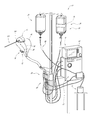
- FIGS. 30 illustrate another embodiment of catheter assembly in which a dilating structure is integrated into an impeller housing
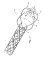
- FIG. 31 show the catheter assembly of FIG. 30 in an expanded configuration with a guidewire in position
- FIG. 32 is a plan view of the catheter assembly of FIG. 30 in an expanded configuration with the guidewire removed;
- FIG. 33 is a detailed view of the distal end of an impeller assembly showing details of an expandable tip
- FIG. 34 show the catheter assembly of FIG. 30 in position within the anatomy
- FIG. 35 illustrates deflection of an impeller housing when a load is applied to a distal portion thereof
- FIG. 36 illustrates a wall pattern in a flat configuration that is configured to isolate an impeller region of an impeller assembly from a load such as that illustrated in FIG. 35 ;
- FIG. 36A-D illustrate in greater detail various regions of the wall pattern in FIG. 36 ;
- FIG. 37A-B illustrates additional techniques for isolating an impeller region of an impeller housing from a load
- FIGS. 38-40 illustrates further embodiments of wall patterns than can be incorporated into an impeller housing
- FIG. 41 illustrates another embodiment of a wall pattern than can be incorporated into an impeller housing to enhance the efficiency of an impeller disposed therein.
- Section II describes distal end features application and performance of heart pumps.
- Section II(A) describes structures that facilitate advancement of a heart pump within the vasculature;
- Section II(B) describes impeller housing configurations that enhance fluid handling performance;
- Section II(C) describes stabilizing structures for an impeller housing to control tip gap clearance.
- Section III illustrates techniques for reducing the complexity and crossing profile of a catheter assembly.
- Section IV describes features of an impeller assembly for improved performance when subject to operational loads during a heart pumping procedure.
- Section V discloses embodiments of an impeller housing for enhancing the flow of blood during operation of the impeller.
- Section VI illustrates methods for use in connection with specific structures of heart pumps.
- FIG. 1 illustrates one embodiment of a heart pump 10 that includes a catheter assembly 100 having a proximal end 104 adapted to connect to a motor 14 and a distal end 108 (as shown in FIG. 1A ) adapted to be inserted percutaneously into a patient.
- the motor 14 is connected by a signal line 18 to a control module 22 that provides power and/or control signals to the motor 14 .
- the heart pump 10 may have an infusion system 26 and a patient monitoring system 30 .
- the infusion system 26 can provide a number of benefits to the heart pump 10 which are discussed below.
- the infusion system 26 includes a source of infusant 34 , a fluid conduit 38 extending from the infusant source 34 to the proximal end 104 of the catheter assembly 100 and a fluid conduit 42 extending from the proximal end of the catheter assembly 100 to a waste container 46 .
- the flow of infusant to and from the catheter assembly 100 can be by any means, including a gravity system or one or more pumps.
- the infusant source 34 includes an elevated container 50 , which may be saline or another infusant as discussed below. Flow from the elevated container 50 can be regulated by a pressure cuff 54 to elevate the pressure of the fluid in the container 50 to increase flow or by a pinch valve 58 or by other means.
- the patient monitoring system 30 can be used to monitor the operation of the patient and/or the pump 10 .
- the patient monitoring system 30 can include a user interface 60 coupled with a source of data 64 .
- the data source 64 can include one or more patient conditions sensors, such as pressure sensors 68 that are in pressure communication with the patient and/or operating components within the patient.
- the pressure sensors 68 fluidly communicate by a conduit 72 that extends between the sensors and a proximal portion of the catheter assembly 100 .
- the conduit 72 can include a plurality of separable segments and can include a valve 76 to enable or disable the pressure communication to the sensors 68 .
- the heart pump 10 is adapted to provide an acute or other short-term treatment.
- a short-term treatment can be for less than a day or up to several days or weeks in some cases. With certain configurations the pump 10 can be used for a month or more.
- FIG. 1A illustrates one embodiment of a catheter assembly to be used with the heart pump 10 .
- An impeller assembly 116 disposed at the distal end 108 is configured to pump blood proximally or distally through or along a portion of the heart pump 10 to convey blood from one body cavity to another.
- the impeller assembly 116 can be arranged to pump blood distally, such as in a right heart assist mode to move blood from the right ventricle to the pulmonary artery. Proximal flow is optimal for left heart support to move blood from the left ventricle to the aorta.
- the heart pump 10 can be used to treat patients with acute heart failure, ST elevation myocardial infarction (STEMI), cardiac arrest, cardiac arrhythmia or other heart maladies.
- the heart pump 10 also can be used in connection with a surgical treatment to support the patient without providing full cardiovascular bypass. A patient could be supported on the device for longer term with proper controls and design.
- the catheter assembly 100 with a low profile configuration.
- the distal end 108 of the catheter assembly 100 can be configured to have about an 11 French (approximately 3.5 mm) size in a first configuration for insertion and an expanded configuration, such as up to about 21 French (approximately 7 mm) once in place in the body.
- the larger size facilitates greater flow rates by the impeller assembly 116 as discussed below.
- the catheter assembly 100 is configured to enable the distal end 108 to reach a heart chamber after being inserted initially into a peripheral vessel.
- the catheter assembly 100 can have a suitable length to reach the left ventricle and sufficient pushability and torquability to traverse the intervening vasculature.
- the catheter assembly 100 may include a multilumen catheter body 120 that is arranged to facilitate delivery and operation of an impeller of the impeller assembly 116 . Further details concerning various embodiments of the catheter body 120 are illustrated in FIGS. 7-7B and described in more detail in U.S. Provisional Application No. 61/430,129, filed Jan. 5, 2010.
- a drive system is provided to drive an impeller within the impeller assembly 116 .
- the drive system includes the motor 14 and a drive controller, which can be integrated into the control module 22 .
- the motor 14 may be configured to be disposed outside the patient, some structures and assemblies described herein could be incorporated into a system in which a motor is miniaturized sufficiently to be inserted into the patient in use, including into the vasculature.
- a torque coupling system is provided for transferring torque from the motor 14 to the impeller assembly 116 .
- the torque coupling system is discussed further in U.S. Provisional Application No. 61/430,129, filed Jan. 5, 2010, but in general can include a mechanical or magnetic interface disposed between the motor 14 and a drive assembly illustrated in FIG. 11 that is disposed at the proximal end 104 of the catheter assembly 100 .
- the drive assembly is coupled with a proximal end of an elongate drive shaft 148 in one embodiment.
- the drive shaft 148 extends between the drive assembly 146 and the impeller assembly 116 .
- a distal portion of the drive shaft 148 is coupled with the impeller assembly 116 as illustrated below in connection with one embodiment illustrated in FIGS. 4A and 4B .
- FIG. 11 shows one manner of coupling the proximal end of the drive shaft 148 with the drive assembly 146 .
- FIG. 1A shows an infusion inflow assembly 150 that can form a part of the infusion system 26 (see FIG. 1 ).
- the infusion in the assembly 150 is provided adjacent the proximal end 104 in one embodiment.
- the infusion system 26 is configured to convey one or more fluids therein in connection with operation of the impeller assembly 116 or the conducting of the treatment.
- an infusant e.g., a medication or a lubricating fluid, such as saline or other beneficial medium, is conveyed distally along the pump, e.g., within the catheter body 120 , toward operating components adjacent the distal end 108 .
- the infusant can include lubrication fluids such as glucose or other biocompatible lubricants.
- the infusion inflow assembly 150 includes a catheter body 154 having a luer or other suitable connector 158 disposed at a proximal end thereof and an inflow port in fluid communication with one or more lumens within the catheter assembly 100 .
- a lumen extending through the catheter body 154 is adapted to be fluidly coupled with a fluid source connected to the connector 158 , to deliver the fluid into the catheter assembly 100 and through one or more flow paths as discussed below in connection with FIGS. 4A , 4 B, and 7 - 7 B.
- the infusion system 26 may also include an outlet positioned at a location that is outside the patient when the heart pump 10 is in use, such that at least a portion of the infusant can be removed from the heart pump 10 and the patient during or after the treatment.
- An infusant outlet assembly can include a lumen, e.g., within the fluid conduit 42 , that is fluidly coupled with an infusant return flow path in the catheter body 120 through a proximal end mechanical interface, for example.
- the catheter assembly 100 can also include a sheath assembly 162 configured to constrain the impeller assembly 116 in a low profile configuration in a first state and to permit the impeller assembly 116 to expand to the enlarged configuration in a second state.
- the sheath assembly 162 has a proximal end 166 , a distal end 170 , and an elongate body 174 extending therebetween.
- the elongate body 174 has a lumen extending between the proximal and distal ends 166 , 170 .
- the lumen is configured to be slidably disposed over the catheter body 120 .
- the arrangement permits the sheath assembly 162 to be positioned between an advanced position corresponding to the low profile configuration and a retracted position corresponding to the enlarged configuration.
- a luer 102 or other suitable connector is in fluid communication with the proximal end 166 of the sheath assembly 162 .
- the luer 102 can be configured to deliver fluids to the catheter assembly 100 , such as priming fluid, infusant, or any other suitable fluid.
- FIG. 1A illustrates a retracted position, in which the distal end 170 of the elongate body 174 is at a position proximal of the impeller assembly 116 .
- the distal end 170 of the elongate body 174 is positioned distal of at least a portion of the impeller assembly 116 .
- the sheath assembly 162 can be configured such that distal advancement of the distal end 170 over the impeller assembly 116 actuates the impeller assembly 116 to a low profile configuration, e.g., causing a change from the second state to the first state, as discussed above.
- the elongate body 174 can include a multilayer construction.
- FIGS. 1A and 2 show that a housing 202 is disposed at the distal end 108 .
- the housing 202 can be considered part of the impeller assembly 116 in that it houses an impeller and provides clearance between the impeller and the anatomy to prevent any harmful interactions therebetween.
- the housing 202 and the impeller are also carefully integrated to maintain an appropriate flow regime, e.g., from distal to proximal within the housing.
- FIGS. 2 , 21 A-B, 22 - 23 , and 35 A- 41 show that in some embodiments the housing 202 includes a cage or mesh structure 203 of filaments that extend axially along the housing and that wrap circumferentially around a central area of the housing in which an impeller of the impeller assembly 116 is disposed.
- the mesh structure 203 can take any suitable form, such as being constructed to prevent kinking upon delivery or to control the spacing between a radially outer edge of an impeller and the housing 202 , as discussed below.
- the housing 202 forms a cannula through which blood flows during use of the system.
- the heart pump 10 and intake 202 A is provided at a distal end of the housing 202 .
- the intake can be configured to remain open in operational conditions such as by having a shape that reduces or eliminate suck-down (e.g., suction causing the inlet to get stuck against wall surface) and to keep the inlet open. For example, as shown in FIGS.
- various embodiments of the housing can be arranged with a bulbous shape (e.g., round, spherical, egg-shaped, oblate spheroidal, or any other shape that includes an enlarged portion having a non-linear curved outer surface) to prevent heart tissue from being drawn into the inlet to interfere with operation of the heart pump 10 .
- the shape also is useful to position the inlet from the wall.
- FIGS. 1A and 2 also show that the distal end 108 of the catheter assembly 100 includes an atraumatic tip 182 disposed distal of the impeller assembly 116 in one embodiment.
- the atraumatic tip 182 can have an arcuate configuration such that interactions with a patient's internal tissues are controlled and do not cause trauma thereto.
- the tip 182 can take any suitable shape, which can vary depending on the degree of curvature of the tip.
- the tip is designed to be atraumatic so that after retraction of the guidewire, when the tip is left inside, for example, a ventricle, it cannot cause injury or trauma to the inner wall or endocardial surface of the ventricle resulting from motion of the ventricle.
- the atraumatic tip 182 can include a 180° bend, wherein the distal-most end of the tip 182 is generally parallel to the non-arcuate portion of the atraumatic tip 182 , but extending in the opposite direction (e.g., a j-tip).
- the distal-most end of the tip 182 can be generally perpendicular to the non-arcuate portion of the atraumatic tip 182 , for example as illustrated in FIG. 19A , or at an angle between about 90° and about 180°, for example as illustrated in FIGS. 13A-B .
- the distal-most end of the tip 182 can include a 360° bend, wherein the distal-most end of the tip 182 is generally parallel to the non-arcuate portion of the atraumatic tip, while extending in generally the same direction.
- the arcuate portion of the tip 182 can be coiled greater than 360°. The latter two embodiments may herein be referred to as a pigtail tip.
- FIGS. 3-12B illustrate additional features of the heart pump, as discussed in U.S. Provisional Application No. 61/430,129, filed Jan. 5, 2010 and as set forth in the appendix below.
- FIGS. 13-25 illustrate a variety of heart pumps embodiments that have advantageous distal or working end arrangements. These embodiments provide atraumatic distal tips and coupling of the same with distal portions of a catheter based heart pump. These embodiments also relate to particularly useful constructions of impeller housings that are able to collapse and expand as needed and also interact with blood cells in a minimally traumatic way. These embodiments also provide for secure engagement of an impeller housing with a proximal portion of the heart pump. Features of these embodiments can be interchanged and combined to arrive at different embodiments within the scope of this application.
- the heart pump 10 is configured as a catheter device that will be placed within the heart after being advanced through the vasculature.
- the distal portion of the pump 100 should be as minimally traumatic as possible to the anatomy to be encountered.
- the connection of the distal end of the housing 202 to the tip 182 can be achieved by advantageous mechanical arrangements.
- FIGS. 13-19A illustrate a variety of embodiments for connecting the atraumatic tip 182 to the distal end of the impeller housing 202 .
- FIGS. 13A-13B illustrate another embodiment of the flexible tip assembly 600 and how it can be attached to the impeller housing 202 .
- FIG. 13A shows the distal end of an embodiment of the pump 100 , including the flexible tip assembly 600 , and the sheath assembly 162 disposed proximally thereof.
- the embodiment of FIG. 13A also shows a hub 608 and a flexible member 602 .
- FIG. 13B shows flexible tip assembly 600 and distal members 648 of the impeller housing 202 .
- FIGS. 14 and 15 include a flexible tip assembly 600 having a locking arrangement for coupling the impeller housing 202 to the flexible member 602 .
- the locking arrangement can be configured to lock or secure a component of the impeller housing 202 between two components of the tip assembly 600 .
- These arrangements are sometimes referred to herein as an interface lock because in some cases they secure a distal structure of the housing at an interface between two separable structures.
- separable includes arrangements that can be assembled and disassembled rather than unitary arrangements.
- the flexible tip assembly 600 includes a core member 604 and the hub 608 .
- the flexible member 602 can take any suitable form, but as illustrated in FIG. 15 may include a proximal portion 612 , a distal portion 616 , and an elongate body 620 extending therebetween.
- the distal portion 616 can take any suitable form, but may be made atraumatic, such as by including an arcuate portion as shown in FIG. 15 .
- the proximal portion 612 may be configured to be coupled with a distal portion of the hub 608 .
- the proximal portion 612 can include a flared body that is adapted to be advanced onto the hub 608 .
- the hub 608 is configured to be disposed between the flexible member 602 and the housing 202 .
- the hub 608 may include a distal portion 628 configured to be coupled with a proximal portion 612 of the flexible member 602 .
- an enlarged structure 632 is disposed at the distal end of a tubular body 636 in one embodiment.
- the enlarged structure 632 can be a barb located at the distal end of the hub 608 .
- the proximal end of the hub 608 can include a recess 640 configured to receive the core member 604 therein.
- the core member 604 and the hub 608 are configured to secure therebetween the distal portion of impeller housing 202 .
- FIGS. 14 and 15 show that in one arrangement a recess 644 is provided that is configured to receive a plurality of distal members 648 of the impeller housing 202 .
- the recess 644 can be provided with a profile with a shape similar to the shape of the distal member 648 .
- the core member 604 can be provided with a plurality of recesses dispose in an outer surface thereof.
- each of the recesses 644 is provided with a shape that matches a shape of the distal end of a corresponding one of the members 648 .
- FIG. 14 illustrates one embodiment in which a T-shaped configuration is provided at the distal end of each of the members 648 .
- Each of the recesses 644 similarly is provided with a T-shaped configuration.
- the recess 644 comprises a narrow proximal portion 644 A and a wide distal portion 644 B.
- the narrow proximal portion 644 A is configured to receive a slender length of the members 648 and the wide distal portion 644 B is configured to receive a distal-most end portion of the member 648 , which has a transverse width that is greater than the width of the slender length portion of the member 648 .
- the core member 604 and the hub 608 are configured to be securely coupled together such that the members 648 of the impeller housing 202 are secured within the flexible tip assembly 600 .
- FIGS. 14 and 15 illustrate that in one arrangement, a plurality of members 648 is disposed about the perimeter of the distal portion of the impeller housing 202 . In the illustrated embodiment, there are four members 648 at the distal end of the housing 202 . Each of the four members 648 can be received within a corresponding recess 644 of the core member 604 . Thereafter the core member 604 along with the distal ends of the four members 648 disposed in the recesses 644 can be inserted into the recess 640 of the hub 608 .
- a proximal portion of the core member 604 can be provided with an engagement feature 660 configured to couple with a corresponding engagement feature 664 disposed on the hub 608 .
- the engagement feature 660 disposed on the core member 604 comprises an arcuate protrusion extending away from a side surface 668 of the core member 604 .
- the corresponding engagement feature 664 disposed on the hub 608 includes an arcuate recess 672 disposed within the recess 640 of the hub 608 .
- the engagement feature 660 and recesses 640 , 672 are more clearly shown on FIG.
- the arcuate protrusion that forms a least a part of the engagement feature 660 can include a plurality of protrusions disposed about the core member 604 . In various embodiments, protrusions are disposed at least on opposite sides of the core member 604 . In one embodiment the engagement feature 660 substantially surrounds the outer surface of the core member 604 . In one embodiment, the recess 672 comprises a circumferential channel surrounding the recess 640 of the hub 608 .
- a lumen 676 extends through at least one of the components of the flexible tip assembly 600 .
- the lumen 676 extends from the proximal end of the core member 604 to the distal end of the flexible member 602 .
- the lumen 676 enables advancement of a guide wire through the pump, e.g., from the distal end of the elongate body 620 into the impeller housing 202 .
- FIG. 16A shows the proximal end of the elongate body 602 advanced over the enlarged structure 632 of the hub 608 .
- the proximal end of the elongate body 602 is advanced into engagement with a distal-facing shoulder 682 of the hub 608 .
- a length of the hub 608 extending proximally from the distal-facing shoulder 682 of the hub has a progressively larger outer perimeter, forming a dilating structure 686 .
- the dilating structure 686 is disposed between the distal facing shoulder 682 and a proximal-facing shoulder 690 of the hub 608 .
- the proximal facing shoulder 690 is disposed proximal of the distal end of the recess 640 .
- FIGS. 13A and 16A shows that the proximal-facing shoulder 690 is configured to abut against a distal end of the sheath assembly 162 .
- This configuration provides a generally smooth transition between the distal-facing shoulders 682 and the proximal-facing shoulder 690 as well as at the interface between the sheath assembly 162 and the proximal-facing shoulder 690 .
- a smooth transition is provided along the entire length from the distal facing shoulders 682 to the proximal facing shoulders 690 .
- a securement device 694 can be provided for coupling one or more of the members 648 to the core member 604 or within the hub 608 .
- the securement device 694 can be used to supplement the locking arrangement between the core member 604 and the hub 608 .
- a mating arrangement is provided between the distal end of the members 648 and a corresponding recess in at least one of the core member 604 and the hub 608 .
- the mating arrangement can include the recess 644 as discussed above.
- the recess 644 can be eliminated and the securement device 694 can be relied upon primarily for securing the member 648 .
- the securement device 694 can comprise an adhesive layer disposed over the distal end portion of one or more the members 648 .
- the securement device 694 can extend distally from the distal end of one or more of the member 648 onto the outer surface of the core member 604 .
- FIG. 16 illustrates another embodiment that is similar to embodiment of FIGS. 13 A/B- 16 A except as set forth below.
- FIG. 16 illustrates a flexible tip assembly 600 A that is configured to provide a barrier to isolate certain components of the flexible tip assembly 600 from the lumen 676 .
- a secondary securement device 694 includes an adhesive
- a distal portion of the recess 640 includes an annular protrusion 710 .
- the annular protrusion 710 can have a portion of the lumen 676 extending therein.
- a well 714 is disposed around the annular protrusion 710 in one embodiment.
- the well 714 can be configured as an annular recess extending distally of the proximal end of the annular protrusion 710 .
- the well 714 is configured to receive at least a portion of the core member 604 .
- the volume within the well 714 is sufficient to also accommodate at least a distal portion of the secondary securement device 694 which, as discussed above, can be an adhesive.
- a distal portion of the core member 604 comprises a recess 718 configured to receive the annular protrusion 710 .
- the interface between the annular protrusion 710 and the recess 718 is configured to minimize or prevent any adhesive or other portion of the secondary securement device 694 from entering the lumen 676 .
- the flexible tip assembly 600 A is similar to the flexible to assembly 600 .
- FIG. 17 illustrates a flexible tip assembly 600 B as similar to the flexible tip assembly 600 except as set forth below.
- the flexible tip assembly 600 B is configured to minimize the likelihood of the hub 608 becoming decoupled from the core member 604 B, for example if forces in opposite directions are applied to the flexible member 602 (e.g., distally directed) and the members 648 (e.g., proximally directed) or a portion of the impeller housing 202 . In one embodiment, this benefit is achieved by modifying the core member 604 B to enable the core member 604 B to directly connect to the proximal portion 612 of the elongate body 620 .
- the core member 604 B can have an elongated distal portion 730 that extends distally of the distal end of the hub 608 .
- elongated distal portion 730 comprises an enlarged portion 734 in the distal end there of, a distal facing shoulder 738 , and the lumen 676 extending therethrough.
- the proximal portion 612 of the elongate body 620 can be received over the enlarged portion 734 and advanced into engagement with the distal facing shoulder 738 .
- Securement of the core member 604 B within the hub 608 is similar to that described in connection with FIG. 13 A/B- 16 A.
- FIGS. 18A-18B illustrate an embodiment of a flexible tip assembly 600 C that is similar to the embodiment of FIG. 17 except as set forth below.
- a hub 608 C having an elongated distal portion is provided.
- the elongated distal portion can comprise a distal end 742 that is disposed distally of the enlarged portion 734 and the core member 604 B when the flexible tip assembly 600 C is assembled.
- the hub 608 C includes a tapered outer surface 746 extending from the distal end 742 toward the proximal facing shoulder 690 .
- the hub 608 C includes a bore 750 extending from the proximal end thereof to the distal end 742 .
- the bore 750 is configured with different widths at different longitudinal positions.
- the bore 750 can be stepped such that it has a smallest diameter at or adjacent to the distal end.
- the diameter can be larger at the location where the enlarged portion 734 of the core member 604 B is disposed when the tip assembly 600 C is assembled.
- the hub 608 C can impede axial, e.g., distal motion of the core member 604 B relative to the hub 608 C.
- the diameter of the bore 750 can be substantially constant along the length between the location where the enlarged portion 734 is disposed and the location where a further enlargement of the bore 750 is provided.
- the region of further enlargement can be configured to receive a portion of the core member 604 B that couples with the members 648 of the impeller housing 202 .
- FIG. 18A shows a transition from the flexible member 602 to the tapered outer surface 746 and from the tapered outer surface to the outer surface 164 of the distal portion of the sheath assembly 162 .
- Such tapering can be advantageously configured to facilitate advancement of a percutaneous heart pump within the body.
- the outer surface 746 can act as a dilating structure in use.
- the flexible member 602 is eliminated and the complexity of the distal section can be reduced by integrating a dilating structure into a distal portion of the housing 202 as discussed in connection with FIGS. 30-34 below.
- FIG. 19 shows another embodiment of a flexible tip assembly in which a plurality of members 648 of an impeller housing 202 are joined at their distal ends by a circumferential structure 760 .
- the circumferential structure 760 includes an arcuate structure extending at least between each of the members 648 .
- the arcuate structure can be a ring that can be joined to each of the members 648 or a unitary ring-like arrangement bridging the distal ends of the members.
- the circumferential structure 760 is disposed between the core member 604 and the hub 608 .
- the circumferential structure 760 is received within a recess formed in the outer surface of the core member 604 .
- the circumferential structure 760 can enhance the security of the distal ends of the member 648 .
- twisting or movement due to torque on the members 648 or the impeller housing 202 can be reduced or eliminated.
- FIG. 19 Another advantage of the embodiment of FIG. 19 is that a rounded surface on the proximal portion of the core member is provided facing proximally toward the impeller housing 202 .
- This rounded surface is one arrangement that can reduce the tendency of thrombogenesis at the proximal portion of the core member or adjacent to the impeller housing 202 .
- this feature can be combined with those of other embodiments to provide additional embodiments.
- FIG. 19A illustrates another embodiment of a flexible tip assembly 600 D.
- the flexible tip assembly 600 D can include a hub 608 D, a core member 604 D, and a flexible member 602 D.
- the hub 608 D can have an increasing outer profile (e.g., outer diameter) along its length.
- the hub 608 D can have a generally constant outer profile (e.g., outer diameter) along its length.
- the hub 608 D can at least partially enclose the core member 604 D, described further below.
- the hub 608 D can have one or more other characteristics of the hubs of the other flexible tip assemblies described herein.
- the hub 608 D can be coupled with a proximal end of the flexible member 602 D. As illustrated in FIG. 19A , the hub 608 D can be coupled with the flexible member 602 D through the core member 604 D.
- the core member 604 D can include a rounded proximal surface facing proximally toward the impeller housing. As described herein, this rounded surface is one arrangement that can reduce the tendency of blood to pool in or adjacent to the impeller housing.
- the core member 604 D can have an elongated distal portion 730 D that extends distally of the distal end of the hub 608 D.
- elongated distal portion 730 D comprises an enlarged portion 734 in the distal end thereof, a distal facing shoulder 738 D, and a lumen 676 D extending therethrough.
- the proximal portion 612 D of the elongate body 620 D can be received over the enlarged portion 734 D and advanced into engagement with the distal facing shoulder 738 D.
- Securement of the core member 604 B within the hub 608 D can be similar to that described in connection with FIG. 13 A/B- 16 A.
- the flexible member 602 D which can be an elongate tubular member, can take any suitable form, but as illustrated in FIG. 19A , can include a proximal portion 612 D, a distal portion 616 D, and an intermediate portion 620 D extending therebetween.
- the distal portion 616 D can advantageously be made atraumatic, for example by including a tapered portion as illustrated in FIG. 19A .
- the proximal portion 612 D can be configured to be coupled with (e.g., advanced over a portion of) the core member 604 D, for example, via friction fit and/or an adhesive.
- the proximal portion 612 D can have a tapered outer diameter that tapers distally towards the intermediate portion 620 D.
- the tapered outer diameter of the proximal portion 612 D can advantageously contribute to the atraumatic and pliable nature of the flexible member 602 D through a gradually decreasing wall thickness (stiffness) from proximal to distal portion of the member.
- the intermediate portion 620 D can be curved and/or can include a constant outer diameter.
- the curvature of the intermediate portion 620 D can take any suitable form, such as those described herein with respect to the atraumatic tip 182 .
- the intermediate portion 620 D can take the shape of a j-tip or a pigtail tip.
- the distal-most end of the intermediate portion 620 D can curve around such that the distal portion 616 D is generally perpendicular to the proximal-most end of the intermediate portion 620 D, as illustrated in FIG. 19A .
- the distal portion 616 D can have a tapered outer diameter that can be configured to reduce trauma to the patient upon insertion and/or retrieval.
- the inner diameter of these structures can remain constant, e.g., the lumen 676 D that extends through the flexible tip assembly 600 D can have a constant diameter.
- the flexible tip assembly 600 D can be configured to be coupled with the distal members 648 D (e.g., structural members) of the impeller housing as described herein.
- the distal members 648 D can be received within a space created between the core member 604 D and the hub 608 D.
- the flexible tip assembly 600 D can include a locking device as described herein that is disposed between the distal members 648 D and the hub 608 D to prevent the flexible member 602 D from being separated from the distal members 648 D.
- the components of the various flexible tip assemblies described herein can be interchangeable, as desired by those skilled in the art.
- a unitary hub structure and enable coupling of the hub to a distal portion of an impeller housing.
- a distal portion of an impeller housing is insertable in a secure manner into slots in a hub.
- the hub can be molded around a distal portion of an impeller housing with the distal portion having features to enhance the mechanical connection between these components.
- FIG. 20 illustrates further features for coupling portions of a flexible tip assembly similar to those discussed above in which a plurality of slots 784 is formed in a proximal aspect of an atraumatic tip.
- the atraumatic tip can include a flexible J-tip (e.g., an atraumatic tip) member and a hub 788 formed with or coupled with the J-tip member, similar to those described above or formed as a unitary body.
- the slots 784 can be formed in a proximal end of the body of the hub 788 and can be configured to receive and be secured to distal end portions of a plurality of members 792 , which extend from or form a portion of the impeller housing 202 .
- the members 792 can be adapted to be inserted into the slots 784 .
- the end portion of the members 792 can include a locking feature configured to be engaged by a receiving feature in a proximal aspect of the hub 788 .
- the receiving feature can be a narrow aperture into a wider portion of the slot 784 .
- the locking feature on the members 792 can include an enlarged section that is adapted to be insertable through the receiving feature but not to be retractable under forces experienced in the use in the body.
- the enlarged section can include as a barb or a plurality of barbs in some embodiments.
- a further enhancement of the flexible tip assembly can include an adhesive or other securement device at least partially disposed in the slots 784 .
- the adhesive can be configured to substantially fill the slots 784 to reduce any space for blood pooling around the tip assembly, which could lead to thrombus formation.
- the slots 784 are covered with a material that prevents pooling around the tip assembly without providing an adhesive or other device for providing securement.
- FIG. 21-21B illustrate other embodiments for enhancing the securing of a connection between a distal portion of an impeller housing and a hub.
- a distal portion of a member 796 forming a distal portion of a variation of the impeller housing 202 includes a feature for integrating the member 796 with a hub body or other component of a flexible tip assembly.
- the feature for integrating the member 796 comprises a through-hole 800 through which a moldable material may flow or bridge.
- the through-hole 800 permits a first portion of molded material to be formed on an inside portion of the member 796 , a second portion of molded material to be formed on an outside portion of the member 796 and a third portion to extend through the through-hole 800 to integrally form with the first and second portions to create a unitary body through and surrounding the member 796 .
- the through-hole 800 is replaced with a recess that extends only partly through the thickness of the member 796 .
- the recess is configured such that a volume of material that forms a hub into which the member 796 can be incorporated can be received therein.
- a step or ledge is formed between the recess and the surface of the member 796 . Interactions between this step or ledge and material of the hub spanning across the step or ledge limits or prevents relative movement therebetween.
- FIG. 21A shows details of a distal portion of one embodiment of an impeller housing 202 A having a mesh structure 203 A. Details of variations of the pattern of the mesh structure are set forth in U.S. application Ser. No. 12/829,359, filed Jul. 1, 2010 and in U.S. Pat. No. 7,841,976, issued Nov. 30, 2010. These documents are hereby incorporated by reference herein in their entirety for all purposes.
- FIG. 21A shows that a distal portion 806 of the mesh 203 A includes a plurality of elongate filaments 808 extending from distal apices 809 of the mesh 203 A. The elongate filaments 808 terminate in a securement feature 810 .
- FIG. 21A shows that a distal portion 806 of the mesh 203 A includes a plurality of elongate filaments 808 extending from distal apices 809 of the mesh 203 A. The elongate filaments 808 terminate in a securement feature 810 .
- the securement feature 810 is the distal most structure of the mesh 203 A.
- the securement feature 810 comprises a circular structure branching laterally from a longitudinal axis of each of the filaments 808 .
- the circular structure can be an annulus as illustrated in FIG. 21A or can be a disc that is configured to enhance securement of the filament 808 to a hub, similar to the hub 788 or to other distal structure.
- a disc could be provided with a recess or cavity on the inner side or outer side of the mesh structure 203 A.
- a disc could be provided with one or more protrusions on one or more of the inside and outside of the mesh 203 A.
- FIG. 21B is a variation of the structure of FIG. 21A with modified filaments 808 A that are configured to provide for securement of the distal portion 806 over a distal length 812 rather than at the distal end of the filament as in FIG. 21A .
- FIG. 21B shows that in one embodiment, each of the filaments 808 A can be provided with a plurality of securement features 810 A disposed along the distal length 812 . In one embodiment, more than one securement feature 810 A is provided.
- the securement features 810 A can be through-holes recesses, or protrusions. As shown, three securement features configured as through-holes can be provided along the distal length 812 of each of the filaments 808 A.
- the coupling can be spread over multiple points, providing redundancy in the securement to assure that the mesh will not be inadvertently detached from a hub with which it is connected. Also, by securing these components over a length, any twisting of the filaments 808 A relative to a hub due to a torque applied to either structure will be reduced or eliminated.
- the impeller housing 202 provides critical functions for the heart pump 10 .
- a key functional capability of the housing 202 in certain embodiments is to be able to significantly change in diameter, e.g., to be collapsed and expanded, repeatedly. Also, in certain embodiment the housing 202 is configured to deform in use in response to the approach of the impeller blades 212 as a way to manage separation between the blades and an inner wall of the housing 202 .
- FIGS. 2 and 4A illustrate expanded arrangements of the housing 202 .
- the housing 202 and the impeller blades 212 are collapsed into a profile no larger than the inner diameter of the sheath assembly 162 .
- the housing 202 may be cycled between the collapsed and expanded configurations multiple times.
- the housing 202 can be formed from a shape memory material.
- Shape memory materials include materials that will expand to a predetermined state after being compressed or otherwise stressed. For example, a suitable material will permit the housing 202 to expand from a collapsed state within the transverse profile of the sheath to the expanded state of FIGS. 4A-4B .
- Shape memory materials can also include materials capable of reversibly deforming and/or changing shape in response to a temperature change.
- Suitable shape memory alloys include, but are not limited to, nickel-titanium (nitinol), copper-zinc, copper-zinc-aluminum, copper-aluminum-nickel, and gold-cadmium.
- nitinol nickel-titanium
- copper-zinc copper-zinc-aluminum
- copper-aluminum-nickel copper-aluminum-nickel
- gold-cadmium examples include, but are not limited to, nickel-titanium (nitinol), copper-zinc, copper-zinc-aluminum, copper-aluminum-nickel, and gold-cadmium.
- at least a portion of the housing 202 can be formed from nitinol. In one embodiment, essentially the entire housing 202 can be formed from nitinol. In other embodiments, other shape memory materials, such as shape memory polymers and/or ceramics, can be used. In yet other embodiments, at least a portion of the housing
- shape memory materials can undergo significant deflections and deformation, yet maintain rigidity. Expansion can be due to the elasticity of the material or due to exposure to temperatures above a specific value. Accordingly, incorporating a shape memory material into the housing 202 can contribute to the ability of the housing 202 to significantly change in diameter (e.g., collapse and/or expand radially). Thus, in some embodiments, the housing 202 can be radially collapsible and configured for percutaneous insertion, while also being expandable to an operable diameter to allow the impeller assembly 116 to expand to an operable configuration.
- variations of the impeller housing 202 can have enhanced stiffness or relaxed stiffness.
- one or more blades 212 of the impeller 200 are disposed and rotate within the housing 202 .
- the operation of the pump 100 is highly dynamic, however, because many of the components of the pump are flexible and the pump is positioned in dynamic anatomical structures. Accordingly, the gap between the blades 212 and the housing 202 (also called tip-gap) can be dynamic in some embodiments.
- the tip gap can be controlled by enhancing the stiffness of one or more structures defining the gap, e.g., minimizing deflection of the housing 202 relative to the impeller blade(s) 212 during operation.
- FIGS. 26-29 illustrate embodiments for reducing flow disturbing effects at inlet and outlet locations, some of which involve enhancing stiffness of the housing. Enhancing flexibility is a strategy for enabling the housing 202 to react to pressure to move away from the blade(s) 212 , as illustrated by the embodiments of FIGS. 22 and 23 .
- Controlling tip-gap can be advantageously employed in some embodiments to compensate for movement of the catheter pump system.
- external forces can be applied to the impeller housing during manipulation or operation of the heart pump. These external forces may cause the impeller housing to deflect inwardly toward the blades and can cause contact between the housing and the blades. Maintaining sufficiently large tip-gap can therefore prevent undesirable contact between the impeller housing and the blades of the impeller.
- Example of embodiments that can help to maintain sufficient tip-gap by reinforcing or stiffening a proximal portion and/or an expandable portion of the impeller housing are discussed further in connection with FIGS. 24 and 25 .
- Example of embodiments that help to isolate a zone of the impeller housing disposed about the blades from distal forces applied to the impeller housing distal of the blades are discussed in connection with FIG. 35 and following.
- the pressure created by the operation of the impeller blades can cause the coating material covering the impeller housing to deflect.
- Large deflections of the coating material may be undesirable if the coating contacts the blades during operation, while in other embodiments, at least some deflection of the coating may be desirable (e.g., to prevent an overly rigid coating or to enable the coating to move away from a blade that is deflect toward the coating).
- the compliance of the coating can therefore be modulated by selecting a coating material with the desired material properties, by modulating the thickness of the coating, and determining the appropriate cell size in which the coating is formed, as discussed herein.
- the housing 202 is stiffened to limit movement of a wall of the housing 202 .
- Factors such as pressures or pressure gradients along the length of or transversely across the housing 202 and loads applied to the impeller, impeller blades 212 , or tip of the impeller assembly 116 can cause the clearance between the blades 212 and an inner surface of the housing 202 to vary.
- Other factors include varying pressure in a heart chamber or in a blood vessel adjacent the heart due to the heart being in systole and diastole, which can cause the housing 202 to dynamically change shape if the ventricular walls collapse during systole, which can affect the clearance between the blades and the inner wall of the housing 202 .
- manipulation or operation of the device can induce external forces on the housing, which can also vary the clearance between the blades 212 and the inner surface of the housing.
- the housing is capable of having different stiffnesses at different regions attributed to a mix and match of different characteristics.
- the housing 202 is configured to not flex in response to operational conditions so that a clearance distribution along the length of the cannula is kept above a minimum.
- the stiffness of the housing 202 can be increased to limit movement of the housing relative to the impeller blades in response to external pressures or factors.
- the density of the mesh can be increased. For example, more rings per unit length can be provided to make the housing 202 less responsive to operational conditions.
- the geometry of the circumferential rings can be changed, such as by thickening the cross-section of the individual rings to be stiffer, thus making the housing 202 stiffer.
- a thicker or less compliant coating can be provided over a portion of the length of the housing to enhance the stiffness in the coated region.
- Another embodiment would provide an enhanced connectedness between adjacent rings, such as by increasing the number of connectors between adjacent rings to increase the stiffness of the housing 202 .
- stiffer axial connectors can be provided between adjacent rings to reduce changes in clearance at the stiffened region.
- FIGS. 26-29 illustrate further embodiments that advantageously control the stiffness of the housing 202 to enhance performance.
- the hydrodynamic performance of the heart pump 10 may be impaired by the flexibility of the housing 202 at an inlet 110 into the housing 202 .
- the housing 202 can include a mesh-like structure 203 that is covered or coated with a coating 204 to provide a cannula structure.
- the cannula structure provides a blood flow channel through the housing 202 .
- flapping or other deformation of the coating 204 at inlet 110 may result in an undesirable or too large pressure drop for a given blood flow rate, and may also result in blood damage via hemolysis and/or thrombus formation.
- the expandable portion of the housing 202 may be provided with various inlet and outlet features.
- FIG. 26 shows the distal end of an expandable housing 202 formed using any suitable manufacturing technique to provide a thicker coating 204 and a lip 976 , e.g., a distally oriented protrusion, at the free end of the housing 202 .
- the thickness of the lip 976 has been greatly exaggerated to make the lip 976 more visible.
- the enhanced thickness is not so great as to substantially increase the crossing profile of the catheter assembly 100 .
- the increased thickness of coating 204 and the lip 976 improve the structural stiffness of the cannula inlet.
- FIGS. 27 and 28 show a proximal end portion of a cannula 202 that can be shaped using any suitable process.
- the outlet 111 has a diffuser arrangement 980 at the proximal end of the housing 202 .
- the housing 202 of FIGS. 27 and 28 may have an outwardly flared portion 982 of the outlet 111 and optionally a crisp lip 984 , e.g., a ring, at the proximal end of the coating 204 .
- the outlet 111 may include a plurality of leaflets 986 defined by the end wire structure of mesh 203 and filled with the material of coating 204 .
- each cell or portion of the mesh can be completely filled with the coating material such that no cell is only partially filled with the coating material.
- the coating material can be completely surrounded by struts in the housing.
- the complex geometry of the housing 202 around the outlet 111 can be configured to cooperate with the impeller assembly disposed in the housing 202 .
- a diffuser 990 can be disposed downstream of the blades 212 of the impeller.
- the diffuser 990 can have a tapered outer surface that is configured to create a divergent flow in the housing 202 .
- the outwardly flared portion 982 can advantageously accommodate the flow regime induced by the impeller blades 212 and the diffuser 990 .
- generally axial flow (from left to right in the figure) can be altered to have a radial component by the diffuser 990 .
- the housing 202 has the outwardly flared portion 982 at the location of the diffuser 990 , the radial flow is accommodated without creating excessive back-pressure in the housing 202 .
- the dashed line in FIG. 29 shows that in one embodiment, the outwardly flared portion 982 has a largest radially extent at substantially the same axial position in the heart pump illustrated therein as the largest radial extent of the diffuser 990 .
- the outwardly flared portion 982 enables higher flows for comparable pump configurations compared to an impeller assembly having a diffuser and being mounted in a straight housing.
- the outwardly flared portion 982 also could minimize hemolysis by reducing radial concentration of red blood cells at the axial position of the diffuser 990 .
- the leaflets 986 are advantageous in that they spread out axially the position of the pressure drop that occurs at the outlet 111 from the inside of the housing 202 to the outside thereof. If the pressure drop across the inside-to-outside boundary were concentrated at a single axial location, a generally conical flow pattern might result. Although such a pattern may be acceptable, it would be unlike typical arterial flow which is more random due to the varying pressure in the arterial system. In contrast, by providing the leaflets 986 the outflow is much more random and more consistent with native vascular, e.g., arterial flow.
- the stiffness of the housing 202 can be reduced to permit the housing to flex in response to conditions such as instantaneous pressure rise at the wall. Such a pressure rise may result from the blades 212 being deflected toward the inner wall of the housing 202 .
- the wall is able to expand or be deflected in an advantageous manner.
- a reduction of the stiffness of the housing 202 can be achieved by reducing the density of the mesh in the region where stiffness is desired to be reduced.
- the stiffness of the housing 202 can be reduced by providing fewer circumferential rings or other members per unit length in the region to be made less stiff. In one embodiment illustrated by FIGS.
- the housing 202 can be made less stiff by reducing the stiffness of individual components of the mesh, such as making the rings thinner in a region where enhanced flexibility is desired.
- FIG. 22B shows a detail view of a tip of blade 212 of an impeller adjacent an inner wall W of the housing 202 .
- a gap G between the wall W and the blade 212 corresponds to the clearance between the blade 212 and the wall W.
- FIG. 22B the gap G is illustrated as being very small. A too-small gap can result in hemolysis as discussed herein.
- FIG. 23 illustrates how a pressure adaptive housing 202 A can be configured to maintain an acceptable gap.
- the housing 202 A is made more flexible at least in the region of the blades 212 .
- the wall W of the housing 202 A will be deflected by local pressures due to the operation of the impeller of which the blades 212 are a part.
- the housing 202 A can be configured with a flexible impeller zone 207 (e.g., void or cell area defined by struts with coating material) that will be radially deformed in certain operational conditions.
- a flexible impeller zone 207 e.g., void or cell area defined by struts with coating material
- FIG. 23B shows a portion of the housing 202 A corresponding generally to the flexible impeller zone 207 , e.g., when in use, protrudes from an otherwise continuous cylindrical surface of the wall W to form an internal channel within the housing 202 A corresponding to the shape of the blade 212 .
- the protruding portion creates a gap G 1 that is greater than the gap G in FIG. 22B .
- the enlarged gap G 1 corresponds to more clearance between the blade 212 and the wall W so that red blood cells or other blood components will not be damaged flowing through the impeller zone.
- the protruding portion of the housing 202 A may not always protrude from the otherwise continuous cylindrical surface of the wall W.
- the protruding portion may be configured to protrude only when the heart pump is in use, e.g., when the impeller is deflected under operating conditions.
- the housing 202 A can be used to cause the housing 202 A to provide an enlarged gap or to protrude radially at the impeller zone.
- the housing 202 is coated along its length, but the coating is made thinner in a region where enhanced flexibility would be advantageous.
- housing 202 may be adaptive to the pressures to which it is exposed in use.
- pressure responsive shaping of the housing 202 immediately adjacent to in the impeller inlet plane to be straight or slightly converging or slightly diverging may be useful to optimize radial velocity profile to the impeller.
- These arrangements may be the result of exposing a housing 202 that is configured to be responsive to differences in pressure across cannula due to blood pressure and instantaneous pump through-flow velocity and other factors discussed above. This arrangement may be preferable to requiring significant bell-mouth inlet convergence shaping well upstream of impeller.
- Adaptive cannula shaping can provide a more robust configuration.
- clearances between the impeller blade tips and the cannula inner surface are very difficult to control with realistic manufacturing tolerances and due to deflections in the impeller shaft that can occur due to the impeller shaft not being a perfectly rigid element. If this clearance is too wide, there is a loss of performance. If it is too small, undesirably high fluidic stresses can occur and result in unacceptably high hemolysis, or even result in potentially damaging contact between the impeller blade tip and the cannula inner surface.
- a portion of the housing 202 downstream of the impeller blades 212 is made pressure responsive such that the shape of the housing is induced by the ambient pressure.
- the housing 202 can be configured to present a shape that would provide flow benefits downstream of the blades 212 .
- the housing 202 can be configured to be diverging downstream of the impeller exit plane in a manner that optimizes diffusion downstream of the impeller.
- the housing 202 can be configured downstream of the impeller exit plane in a manner that optimizes deswirl in the downstream flow region.
- Such a shaping can be induced by pressure in the housing 202 during operation or by other conditions, such as blood pressure and instantaneous pump throughflow velocity.
- advantages can be achieved by making the housing 202 pressure adaptive or by configuring the cannula 202 to respond in a predicted manner to the ambient conditions. This can result in a gentler handling of red blood cells and other blood components that can be damaged by conditions such as a too narrow gap between the blades 212 and the housing 202 .
- FIGS. 24-25 illustrate techniques for increasing the stiffness between the expandable portion of the housing 202 and the non-expandable section of the catheter assembly 112 proximally thereof.
- FIG. 24 illustrates an impeller housing 900 that is similar to the impeller housing 202 except as described differently below.
- the impeller housing 900 includes an expandable distal portion 904 and a proximal portion 908 that has a generally fixed profile.
- the proximal portion 908 houses a proximal portion of impeller similar to the impeller 200 .
- An impeller can be supported in a cantilevered manner from the proximal portion 908 of the housing 902 .
- a plurality of members 912 extends between the proximal portion 908 and the expandable distal portion 904 .
- the plurality of members 912 can include a first group of struts 912 A to provide a secure connection between the distal and proximal portions 904 , 908 .
- a plurality of gaps 916 defined between adjacent struts 912 A can be configured to permit blood flowing from an upstream location through the housing 900 to exit the housing at a downstream location.
- the gaps 916 can be disposed within a portion of the vasculature, e.g., the pulmonary artery or the aorta while an intake in of the pump of which the housing 900 is a part can be disposed in a fluid source, such as a chamber of the heart.
- a fluid source such as a chamber of the heart.
- proximal end of the proximal portion 908 of the impeller housing 900 is coupled to a catheter body 920 similar to the catheter body 120 discussed above.
- a proximal section of the impeller housing 900 it is desired to stiffen a proximal section of the impeller housing 900 .
- This can be achieved by providing one or more stiffening members coupled with the proximal portion 908 and a distal portion 904 .
- a second group of struts 912 B is provided between distal and proximal portions 904 , 908 .
- the struts 912 B are located on opposite sides of the impeller housing 900 .
- Each of the struts 912 B includes a distal end 918 coupled with the distal portion 904 and a proximal end 922 coupled with the proximal portion 908 .
- the distal end 918 is coupled with the distal portion 904 at approximately the same longitudinal position as the longitudinal position where the struts 912 A connect to the distal portion 904 .
- the proximal end 922 of the struts 912 B are coupled with the proximal portion 908 at a longitudinal position that is proximal of the longitudinal position where the struts 912 A are coupled with the proximal portion 908 .
- each of the struts 912 B is coupled with the proximal portion 908 at the same longitudinal position.
- a circumferential member 924 which can be a ring, extends between and couples the proximal ends 922 of the struts 912 B.
- FIG. 24 illustrates embodiments that advantageously stiffen the impeller housing 900 , particularly in the region of the proximal portion 908 and in at least a portion of the distal portion 904 in which impeller operates.
- the enhanced stiffness is due to a triangular structure formed between adjacent struts 912 A, 912 B and a length of the proximal portion 908 extending between the proximal ends of the struts 912 A, 912 B.
- This triangular structure provides a rigid configuration like a truss that resists deflection of this proximal zone from a central longitudinal axis of the impeller housing 900 .
- the forced to collapse the expandable distal portion 904 can be increased by the presence of the struts 912 B.
- FIG. 25 illustrates another embodiment of an impeller housing 930 in which the stiffening benefit of struts 912 B is provided while maintaining or reducing the collapsing force needed to collapse the expandable distal portion 904 .
- the impeller housing 930 is similar to the impeller housing 900 except as described differently below.
- at least the struts 912 B are coupled with the structure that is locked in an axial position in a first configuration and that is capable of sliding proximally to a second axial position in a second configuration.
- proximal ends 922 of the struts 912 B are coupled with a slidable circumferential structure 924 B.
- the slidable circumferential structure 924 B can comprise a short sleeve disposed about proximal portion 908 .
- a locking device 934 is provided to hold the circumferential structure 924 B in a first axial position about the proximal portion 908 .
- the locking device 934 may have a first configuration in which at least one of a shoulder is provided to limit the axial travel of the circumferential structure 924 B.
- a distal-facing shoulder is provided.
- proximal and distal-facing shoulders capture the circumferential structure therebetween.
- the locking device 934 includes a ramped proximal portion 938 .
- the locking device 934 can be actuated to a second configuration in which the circumferential structure 924 B is permitted to slide proximally on the proximal portion 908 .
- advancement of the distal end 170 of the sheath assembly 162 into engagement with the ramped proximal portion 938 causes the forward facing shoulder of the locking device 934 to be retracted such that the forward facing shoulder does not prevent proximal movement of the circumferential structure 924 B. Further advance of the distal end 170 of the sheath assembly 162 causes the distal end to engage the struts 912 B.
- the locking device 934 can be actuated by a mechanism disposed on the proximal end of modified version of the pump 100 .
- a tension member such as a wire can be disposed within the catheter assembly 112 .
- a pull wire can be disposed within a peripheral lumen formed in a catheter body similar to the catheter body 120 .
- one of the lumens 282 illustrated in FIG. 7-7C can be configured to house a pull wire. Actuation of the pull wire from the proximal end of the modified pump can cause the locking device 934 to disengage from the circumferential structure 924 B, e.g., to be actuated to a retracted position, permitting movement of the circumferential structure 924 B.
- the locking device 934 can be configured with a proximal locking component and a distal locking component in one embodiment. Where proximal and distal locking components are provided, axial sliding of the circumferential structure 924 B is prevented in both the proximal and distal directions when the locking device 934 is actuated to a locked configuration.
- the locking device 934 includes a retractable latch.
- the enhancement of the stiffness of the proximal portion and a proximal zone of the distal, expandable portion of an impeller housing in embodiments illustrated by FIGS. 24-25 is advantageous in that it provides one approach to controlling undesirable interactions between impeller blades 212 and inner surfaces of the impeller housing. Contact between impeller blades 212 and inner surface of the impeller housing can lead to damage to certain blood components such as red blood cells. At the relatively high blood pump pressures and flows anticipated in the pump 100 , minimizing hemolysis is a significant advantage.
- FIGS. 30-33 illustrate a catheter assembly 1000 with a sheath assembly 1028 and a tip assembly 1004 having an integral dilating structure 1008 .
- the catheter assembly 1000 can be used with a heart pump, as discussed above, and can provide several advantages. For example, by integrating the dilating structure 1008 into the tip assembly, the tip assembly can be used to dilate anatomical structures such as the aortic valve. Also, the configuration of the dilating structure 1008 can be selected to space an intake structure from the anatomy to prevent the anatomy from being sucked into the intake. These embodiments advantageously can be made with fewer parts and benefit from not including a distal flexible member as in some of the other embodiments herein.
- FIG. 31 shows that the catheter assembly 1000 is capable of percutaneous insertion and includes an impeller 1012 having one or more foldable blades 1016 and an expandable housing 1020 surrounding the impeller.
- the housing 1020 can be configured as a cannula in some embodiments.
- the housing 1020 has a collapsed configuration for delivery to a desired location within the body and an expanded configuration in which the impeller can rotate to pump blood.
- the collapsed configuration is illustrated in FIG. 30 and the expanded configuration is illustrated in FIGS. 31-33 .
- FIG. 34 shows the catheter assembly 1000 deployed in the anatomy and in the expanded condition.
- the catheter assembly 1000 includes the sheath assembly 1028 that is similar to those hereinbefore described and can be advanced over a guidewire 1024 .
- the guidewire 1024 can be used to access the anatomy, e.g., the left ventricle as illustrated in FIG. 34 .
- the catheter assembly 1000 can track over the guidewire 1024 to a selected position, e.g., with a proximal portion of the impeller housing 1020 residing in the ascending aorta, the distal portion of the impeller housing 1020 (including the dilating structure 1008 ) residing within the left ventricle, and the impeller housing 1020 generally crossing the aortic valve.
- the dilating structure 1008 positioned within the left ventricle, can then be urged into contact with the aortic valve, e.g., at the ventricular side of the aortic valve, to separate the aortic valve leaflets from each other.
- the catheter assembly 1000 can advantageously enable the catheter assembly 1000 to be advanced through the aortic valve into the heart in a minimally traumatic manner, protecting the aortic valve.
- the dilating structure 1008 may be positioned sufficiently distal to the aortic valve such that it does not contact the aortic valve upon expansion/dilation. Thereafter, the distal portion 1032 of the housing 1020 is disposed in the left ventricle and a proximal portion of the housing 1020 is located in the ascending aorta, as illustrated in FIG. 34 .
- the catheter assembly 1000 When positioned in the anatomy, the catheter assembly 1000 extends proximally to a peripheral access site, such as a femoral access site. After delivery, the guidewire 1024 can be retracted by applying a proximally directed force while holding the proximal end of the catheter assembly in place.
- FIG. 34 illustrates a method in which the guidewire 1024 is left in place after the sheath 1028 , shown in FIG. 32 has been retracted.
- the housing 1020 is expanded before the guidewire 1024 is removed.
- the guidewire 1024 is first removed, then the sheath assembly 1028 is retracted permitting the housing 1020 and the impeller blades 1016 to be expanded.
- the guidewire 1024 should be completely retracted prior to and/or during operation of the device (e.g., the guidewire 1024 should be removed before the device is operated.)
- FIGS. 31 and 33 show that the dilator 1008 includes a port 1040 configured to receive the guidewire 1024 .
- the guidewire 1024 can also be advanced through the impeller 1012 in various embodiments. Further features that facilitate advancement of a guidewire through an impeller are described in U.S. patent application Ser. No. 12/829,359, filed Jul. 1, 2010.
- the dilator 1008 can be configured as a plurality of arms 1044 extending outward and proximally from the port 1040 .
- the arms 1044 form a substantially continuous surface extending proximally from the port 1040 in the collapsed state (see FIG. 30 ) and a substantially blunt structure in the expanded state (see FIG. 32-33 ).
- each arm 1044 can extend from a central hub 1048 disposed around the port 1040 to a proximal end 1052 disposed away from the hub 1048 .
- the proximal end 1052 may be joined to a distal end 1054 of an elongate structural member 1058 , a proximal end 1062 of the member extending from a mesh of expandable members forming the housing 1020 .
- the housing 1020 can optionally include a covering or coating and in the embodiment of FIGS. 30-34 , a distal portion 1070 of the coating extends a portion of the length of the elongate members 1058 .
- FIG. 32 illustrates that coating the distal end presents a transverse size (e.g., cross-sectional area, diameter, or height in the view of FIG. 32 ) that is significant larger than the transverse size of the central portion of the housing 1020 . This enables a gentle intake of blood into the lumen in the housing 1020 .
- Each arm 1044 may be configured to couple with a distal portion of the sheath assembly 1028 .
- a proximal portion of each arm 1044 has a reduced thickness such that the distal end of the sheath assembly 1028 can be urged up into abutment with a proximal ridge 1072 of the thicker, distal portion of the arms 1044 .
- This sliding and abutting provides a minimum step up in diameter from the diameter of the arms 1044 to the diameter of the sheath assembly 1028 so that transition from the arms 1044 to the sheath assembly will slide through the anatomy with ease.
- FIG. 33 illustrates a relief area 1066 provided between adjacent arms 1044 to enable the arms 1044 to more closely conform to a gradually proximally expanding structure that would be suitable for dilating tissue.
- the dilator 1008 as an integrated part of the expandable housing structure, enables the catheter assembly 1000 to be advanced through the vasculature without an independent delivery sheath being disposed between the sheath assembly 1028 and the patient, which is typical in percutaneous procedures.
- the elimination of the independent delivery sheath preserves a greater percentage of the crossing profile for the catheter assembly 1000 .
- This can be advantageous in permitting an increase in the size of the impeller 1012 , which can enhance flow output of a heart pump incorporating the catheter assembly 1000 .
- catheter assembly 1000 provides efficient intake of blood in use. Additionally, the blunt configuration of this inlet portion overall greatly reduces the likelihood that the anatomy adjacent the intake will be sucked into the intake to interfere with operation of the pump. In other words, expansion of the cannula simultaneously expands the tip of the dilator 1008 , which serves to space the inlet of the cannula assembly 1000 from the inner heart wall W and other structures within the heart during a pumping operation.
- FIGS. 35-38 illustrate embodiments that advantageously isolate the portion of a housing (e.g., the housing 202 , 1020 or other housings described herein) in which an impeller operates from deflections that could be induced by the moving anatomy in which the heart pump 10 operates.
- a housing e.g., any housing described herein
- the heart pump 10 operates more effectively when a controlled gap is provided between the spinning impeller 200 and the inner wall of the housing 202 , which forms a cannula. This also applies to the housing 1020 and impeller 1012 of the catheter assembly 1000 .
- FIG. 34 shows that the tip assembly 1004 of the catheter assembly 1000 is disposed in the left ventricle and may be exposed in use to the movement of the beating heart, such as the wall W. This motion may adversely affect the alignment between the impeller 1012 and the inner wall of the housing 1020 .
- FIG. 35 shows that movement at the distal portion of the housing 202 (or housing 1020 ) due to interaction with the wall W could result in bending at the proximal portion of the housing in the area where the impeller 200 (or impeller 1012 ) operates.
- a bending load L applied at the distal end 108 of the housing 202 or a transverse displacement D of the distal end 108 from a straight projection of the orientation of the proximal end 104 can create a transition zone 1090 adjacent to an impeller zone 1092 where the impeller 200 operates.
- Having uniform stiffness along the length of the housing 202 distal the impeller 200 can potentially result in a substantially straight length of the housing 202 between the transition 1090 and the distal end 108 .
- This can cause the transition zone 1090 to be localized adjacent to the impeller 200 , which is disadvantageous when the cannula collapses where stress concentrates at the localized region. This can adversely affect the gap between the impeller and the housing 202 .
- FIG. 36-36D illustrate in a flat form a wall pattern 1100 that can be used to form a structure similar to the cage or mesh structure 203 .
- the pattern 1100 includes a proximal portion 1102 a distal portion 1104 and an elongate pattern 1106 extending therebetween.
- the proximal portion 1102 can take any form, but may be rigid enough to be securely coupled with the bearing housing 220 .
- the proximal portion 1102 can form a generally fixed perimeter hollow cylinder configured to be fitted over the bearing housing 220 .
- the distal portion 1104 can be configured to have a low profile for delivery and to expand to permit efficient intake of blood, such as by forming openings similar to the openings 1074 discussed above when expanded.
- the low profile can be the same as or similar to or smaller than that of the proximal portion 1102 .
- the distal portion 1104 is coupled with an atraumatic tip, such as illustrated and described in connection with FIGS. 13-21B .
- the distal portion 1104 forms a portion of a dilating structure such as the integrated dilating structure 1008 .
- the elongated pattern 1106 can take any suitable form, but may include a plurality of expandable zones with different rigidities to enable isolation of the impeller zone 1092 from the load L illustrated in FIG. 35 .
- the elongate pattern 1106 includes a first expandable zone 1108 disposed adjacent to the proximal zone 1102 .
- the first expandable zone 1108 is configured to closely control the gap between an impeller and the inner wall of a housing into which the wall pattern 1100 is incorporated.
- the first expandable zone 1108 can be configured with the greatest rigidity of all the expandable zones in the elongated pattern 1106 .
- the first expandable zone 1108 corresponds to the location of (e.g., is disposed over) an impeller such as the impeller 202 and can extend along approximately the proximal one third of the elongated pattern 1106 .
- the expandable zone(s) distal of the first expandable zone 1108 provide sufficient ability to isolate the impeller from the load L or displacement D (see FIG. 35 ) that the length of the stiffest portion of the housing can be shortened to less than one-third the length of the housing.
- the elongated pattern 1106 comprises a plurality of zones of different rigidities distal of the first expandable zone 1108 .
- at least one zone can be the same, more, or less rigid compared to the first expandable zone 1108 depending on the flex pattern desired along the housing.
- a second expandable zone 1110 and the third expandable zone 1112 are both less rigid and disposed distally of the first extendable zone 1108 .
- the second expandable zone 1110 can be disposed between the first expandable zone 1108 and the third expandable zone 1112 .
- the second zone 1110 may have a rigidity that is less than that of the first expandable zone 1108 .
- the third expandable zone 1112 has a rigidity that is less than the second expandable zone 1110 .
- the second zone 1110 has a greater ability to deflect in response to the load L or displacement D than does the first expandable zone 1108 .
- the third zone 1112 has the greatest ability to deflect in response to the load L or displacement D of the first, second, and third zones 1108 , 1110 , 1112 . It may even be desirable to configure the second and third expandable zones 1110 , 1112 to deform with the deformation.
- the pattern 1100 can be configured to deform most in the third expandable zone 1112 and progressively less proximally thereof toward the first expandable zone 1108 .
- the distal portion 1104 can be considered a fourth expandable zone dispose distally of the third expandable zone 1112 .
- the distal portion 1104 has a rigidity that is greater than that of the third expandable zone 1112 .
- at least a proximal section 1104 A of the distal portion 1104 can be configured to provide a rigidity that is similar to that of the proximal portion 1102 .
- the distal section 1104 B of the distal portion 1104 can be provided with a plurality of elongate gaps therebetween to provide generally unimpeded intake of blood as discussed above.
- the distal section 1104 B of the distal portion 1104 can also have enhanced flexibility to provide atraumatic interactions with the anatomy.
- FIG. 36A illustrates more detail of one embodiment of the first expandable zone 1108 .
- the first expandable zone 1108 comprises a proximal end 1116 comprising a plurality of longitudinally oriented members 1118 coupled with the proximal portion 1102 .
- the first expandable zone 1108 also includes a plurality of circumferentially oriented rings 1120 arranged along the longitudinal axis of the pattern.
- the rings 1120 may have a sinusoidal configuration.
- the number of rings 1120 can be varied, and may depend on the configuration of the impeller to be disposed within the housing into which the pattern 1100 is incorporated.
- the first expandable zone 1108 includes eight circumferential rings 1120 , while in other embodiments the first expandable zone 1108 includes six or seven circumferential rings 1120 .
- the first expandable zone 1108 can include any suitable number of rings 1120 .
- the circumferential rings 1120 of the first expandable zone 1108 may comprise a plurality of crests and troughs 1122 , 1124 that are distally and proximally oriented.
- FIG. 36A illustrates that the crests 1122 of a first ring in the first expandable zone 1108 are overlap with (e.g., are nested within) the troughs 1124 of a second circumferential ring 1120 , where the second circumferential ring is located distal of the first circumferential ring.
- This arrangement enables a connector 1126 to extend substantially circumferentially from a first location on the first ring to a second location on the second ring.
- the first and second locations can be located just off (e.g., proximal of) a corresponding crest 1122 and just off (e.g., distal of) a corresponding trough 1124 .
- the connector 1126 is relatively short in one embodiment, e.g., having a length that is about equal to the width of the portion of the rings 1120 that extends between the crests and troughs 1122 , 1124 .
- FIG. 38 illustrates an embodiment in which at least some circumferential connectors are widened to enhance stiffness of the structure.
- the width of the connectors 1026 are about equal to or in some cases greater than the length thereof.
- a connector 1126 provides a circumferential connection between a strut forming a crest and a strut forming a trough of different adjacent rings 1120 . Accordingly, the connector 1126 can be referred to herein as a radial/adjacent connector. In the first expandable zone 1108 , the connectors 1126 are located at the same axial position such that a cross-section perpendicular to the length of the pattern 1100 would intersect all of the connectors 1126 .
- the nested arrangement of the crests and troughs 1122 , 1124 of the adjacent circumferential rings 1120 (i.e., the proximity between adjacent crests and troughs) provides enhanced rigidity in the first expandable zone 1108 .
- the nested arrangement of the crests and troughs 1122 , 1124 of the adjacent circumferential rings 1120 is approximately 50% overlapped in width. In some arrangements, nesting of crests and troughs 1122 , 1124 is not provided, which would result in a more flexible structure all else remaining equal.
- nesting of the crests and troughs 1122 , 1124 can be as much as 80% overlapped in width, or limited by the material and manufacturing capabilities, which would result in a less flexible structure all else remaining equal.
- connectors 1126 between each adjacent crest and troughs 1122 , 1124 further enhancement of the rigidity of the first expandable zone 1108 is provided.
- a connector 1128 that is generally axially oriented is provided between adjacent circumferential rings 1120 .
- the connector 1128 extends from a first end 1128 A (e.g., a crest) coupled with proximal side of each trough 1124 and a second end 1128 B coupled with a side portion (e.g. an arm extending between a crest and trough) of a circumferential ring 1120 disposed proximally of the first end 1128 A.
- the connector 1128 can be referred to herein as an axial-to-side connector.
- the connector 1128 can take any suitable form, and in some embodiments are included mainly to facilitate collapsing of the housing into which the pattern 1100 is incorporated.
- the connector 1128 can be sinusoidal in form, for example having, in one example, a plurality of apices, such as at least three apices between the first and second ends 1128 A, 1128 B.
- the connectors 1128 can be straight to provide greater rigidity to facilitate retraction of the housing into a sheath, as discussed above.
- at least the proximal pair of rings 1120 are connected by variations of the connectors 1128 that are stiffened (e.g., made straight, thicker or wider) to reduce bending adjacent the proximal portion 1102 .
- the second expandable zone 1110 can be made more flexible by any suitable means.
- FIG. 36B illustrates that the second extendable zone 1110 can be configured with enhanced flexibility by eliminating the connector 1126 between at least some of the rings 1120 .
- FIG. 36B illustrates that in one embodiment at least a plurality of (e.g., at least four) adjacent rings 1120 are not connected to each other circumferentially, however in some embodiments at least five or six adjacent rings 1120 are not connected to each other circumferentially.
- the second expandable zone 1110 can be made more flexible by including a connector 1128 ′, which extends generally axially, instead of connector 1128 .
- the connector 1128 ′ can be elongated, as compared to connector 1128 , to provide enhanced flexibility.
- One technique for making the connector 1128 ′ longer than connector 1128 is to connect the second end 1128 B′ with the trough 1124 of the next-proximal circumferential ring 1120 instead of at a location on the next proximal ring between adjacent troughs and crests. By disposing the first and second ends 1128 A, 1128 B′ farther apart, the connector 1128 ′ can be made longer than an otherwise similar connector 1128 to permit more apices along its length.
- Another technique for enhancing the flexibility of the second expandable zone 1110 is to lengthen the connector 1128 and/or the connector 1128 ′ by increasing the amplitude of the waves along the length of the connector compared to the amplitude in the first expandable section 1108 .
- the connectors are made longer and are able to stretch and move upon application of a similar or lower force, thus being more flexible.
- further flexibility can be obtained by creating a gap between adjacent rings and progressively increasing the amount of gap.
- the flexibility of the expandable zone 1110 is progressively greater in the distal direction. This can be accomplished by lengthening the connectors 1128 and/or the connectors 1128 ′ from one circumferential ring to the next along the length of the second expandable zone 1110 .
- a proximal aspect of the second expandable zone 1110 can include connectors 1128 ′ with a first number of apices (e.g., five apices) and a distal aspect of the second extendable zone 1110 can include connectors 1128 ′ with a second number of apices greater than the first number (e.g., seven apices).
- a proximal aspect of the second expandable zone 1110 can include connectors 1128 ′ with apices having a first average amplitude and a distal aspect of the second extendable zone 1110 can include connectors 1128 ′ with apices having a second average amplitude greater than the first average amplitude.
- Another technique for enhancing the flexibility of an expandable zone is to progressively decrease the amount of nesting of peaks and troughs of adjacent rings.
- the crests and troughs of a first adjacent pair of circumferential rings 1120 can overlap to a greater extent than those of a second adjacent pair of circumferential rings 1120 where the first pair is proximal of the second pair.
- a third expandable zone 1112 can be configured for greater flexibility than the second expandable zone 1110 by decreasing the amount of overlap between adjacent crests and troughs of adjacent circumferential rings 1120 .
- a first pair of adjacent rings 1120 A and a second pair of adjacent rings 1120 B are provided with overlap of length OL 1 and OL 2 respectively.
- the first pair of rings 1120 A is distal to the second pair of rings 1120 B.
- the second pair of rings are disposed in the second expandable zone 1110 and the first pair are disposed in the third expandable zone 1112 .
- the third expandable zone 1112 has an amount of overlap between adjacent rings that varies along the length of the third expandable zone 1112 .
- the overlap amount can vary between each pair of adjacent rings or in a less discrete manner.
- FIG. 40 shows a variation in which overlap is eliminated and spacing is provided that can increase distally.
- Flexibility of the pattern 1106 in the third expandable zone 1112 can also be varied in other ways, such as by lengthening the connectors 1128 ′. Because of their sinusoidal shape, the length of the connectors 1128 ′ can be increased (while incidentally reducing the wavelength of the connectors 1128 ′) without increasing the distance between the adjacent rings (e.g., adjacent rings 1120 A). As illustrated in FIG. 36C , in the distal portion of the third expandable zone 1112 , such as near the first pair of adjacent rings 1120 A, the longitudinal distance between the first and second ends of the connectors 1128 ′ is approximately equal to the longitudinal distance between the peaks and troughs of each circumferential ring 1120 .
- the length of the secondary connector 1128 ′ is much longer than this longitudinal distance. These factors, e.g., the length of the connector 1128 ′, relative to the distance between adjacent rings, can provide greatly enhanced flexibility toward the distal and the third expandable zone 1112 .
- FIG. 36D illustrates in greater detail one embodiment of the distal portion 1104 .
- the proximal section 1104 A for the distal portion 1104 includes a circumferential ring 1120 and a plurality of connectors extending distally thereof.
- a connector 1128 ′ having a sinusoidal form can extend distally of a trough 1122 of the ring 1120 .
- the connector 1128 ′ can include a plurality of apices, for example three apices.
- a connector 1128 ′ expends distally from each trough 1122 of the circumferential ring 1120 .
- a connector 1126 can extend generally circumferentially from a side surface of an arm extending between each trough 1122 and each crest 1124 of the ring 1120 .
- the connector 1126 enhances the stiffness of pattern 1100 in the region of opening for blood intake so that the openings will remain open when a housing incorporating the pattern 1100 is expanded.
- the distal section 1104 B of the distal portion 1104 includes a circumferential ring 1132 and a plurality of axial members 1134 .
- the circumferential ring 1132 may be configured to provide a larger expanded shape than the shape provided by the circumferential rings 1120 .
- the circumferential ring 1132 can include a plurality of proximal troughs 1136 , a plurality of distal crest 1138 , and a plurality of elongate members 1140 extending between the crests and troughs.
- the elongate members 1140 are substantially longer than the corresponding elongate members of the circumferential rings 1120 .
- circumferential ring 1132 when expanded, circumferential ring 1132 provides enlarged perimeter compared to the circumferential rings 1120 .
- the axial members 1134 can take any suitable shape, but may be configured to be integrated into an atraumatic distal structure, as discussed above. Openings are formed between adjacent axial members 1134 , the elongate members 1140 and the troughs 1136 .
- the techniques discussed above advantageously reduce the stiffness of the wall pattern 1100 at a distal location compared to a location at which an impeller will operate in a manner that spreads out deformation of the housing over a length. This isolates the impeller zone from the effect of the load L or displacement D illustrated in FIG. 35 .
- the length of the housing that is deformed is elongated to prevent focused bending that could result in a kinking of the housing, which could result in damage or significant flow blockage.
- the axial spacing between the circumferential rings can be varied at discrete locations or continuously along the length of the housing.
- the first expandable zone 1108 can have a first axial density of circumferential rings 1120
- the second expandable zone 1110 can have a second axial density of circumferential rings 1120
- the third expandable zone 1112 can have a third axial density of circumferential rings 1120 , where at least the third density is less than the first density.
- Example embodiments provide a first axial density of about 8 circumferential structures per inch and a third axial density of about 4 circumferential structures per inch.
- circumferential structure in other embodiments, about one-half the axial density of circumferential structure can be provided in a more flexible zone compared to a less flexible zone. Further embodiments of enhanced flexibility due to changes in spacing of circumferential rings or structures are described below in connection with FIGS. 39 and 40 .
- Varying at least one aspect of sinusoidal rings e.g., the number of crests and troughs, the frequency of crests and/or troughs, and/or amplitude of the rings can also provide stiffness variation along the length of the pattern 1100 .
- the first expandable zone 1108 can have circumferential rings 1120 with a first number of distal peaks and proximal peaks and a portion of the pattern 1100 distal of the first expandable zone 1108 can have circumferential rings 1120 with a second number of distal and proximal peaks, and the first number of distal and proximal peaks can be less than the second number of distal and proximal peaks.
- a transition zone is provided that is configured to have a continuously varying stiffness from the distal end of the first expandable zone 1108 to the proximal section 1104 A of the distal portion 1104 .
- the continuous variation of the transition zone produces an arcuate shape upon application of the load L or displacement D in FIG. 35 . This advantageously eliminates or minimizes the risk of buckling or kinking of the housing into which this modified pattern is incorporated.
- a transition zone can be configured to minimize focused bending or kinking but to assure that if focused bending or kinking occurs, it will occur closer to the distal portion 1104 than to the first expandable zone 1108 .
- FIGS. 37A-37B illustrate a number of connector variations that could be incorporated into the pattern 1100 to modify the stiffness between or within one of the expandable zones.
- a wall pattern 1232 corresponding to the first expandable zone 1108 has a connector 1128 ′ that has a linear configuration, for example, having only 3 apices on the connector and with a smallest amplitude compared to patterns 1240 and 1244 , with a first plurality of (e.g., three) bends or apices that provides a first longitudinal stiffness.
- a wall pattern 1240 corresponding to a portion of the pattern 1100 that is more flexible than the first expandable zone 1108 has a connector 1128 ′ that has a linear configuration with a second plurality of (e.g., five) apices and each with a larger amplitude than the pattern 1232 , that provides a second longitudinal stiffness.
- the second plurality of apices includes more bends than the first plurality.
- a wall pattern 1244 corresponding to a portion of the pattern 1100 that is more flexible than the first expandable zone 1108 has a connector 1128 ′ that is much longer (i.e., having a larger amplitude or connecting material between apices) than the connectors in the patterns 1232 , 1240 and as a result comprises a third longitudinal stiffness that is less than the first or second longitudinal stiffnesses.
- the connector 1128 ′ of the wall pattern 1244 is much longer by spanning the entire width of a trough a plurality of times between tends connected to axially aligned troughs of adjacent rings 1120 .
- FIG. 37B shows further variants in which other variable are modified.
- a wall pattern 1248 is provided in which the radius of curvature of an apex toward the proximal end of a connector 1128 ′ is increased compared to the curvature of other apices.
- one segment of the connector is curved rather than straight.
- This arrangement can be used in a portion of a wall structure where greater stiffness is needed, such as near the members 1118 connect the proximal most circumferential ring to the proximal portion 1120 .
- a wall pattern 1252 can include a connector 1128 with a greater number of apices, e.g., five apices compared to three in pattern 1248 , with comparable amounts of overlap.
- a wall pattern 1256 can provide both a larger number of apices and a lesser amount of nesting or overlap between adjacent rings 1120 .
- the pattern 1256 includes seven apices. The apices have progressively larger amplitude to maximize the length of the connector 1128 ′ for a given trough to trough spacing.
- a wall pattern 1260 provides another means for varying the stiffness of the structure.
- a similar number of apices is provided compared to the pattern 1256 , however, the average amplitude is less.
- gaps G are provided in the unexpanded state between the connector 1128 ′ and the arms of the ring 1120 .
- the length of the connector 1128 ′ is less than it could be given the arrangement of the rings 1120 .
- Wall pattern 1264 provides another variation similar to pattern 1260 except that the average amplitude is maximized by eliminating the gap G and a greater amount of nesting or overlap is provided.
- the resulting structure may have comparable stiffness to that of wall pattern 1264 but provide more material coverage which reduces the surface area that needs to be coated. Also, this arrangement may reduce the percentage contribution of the coating to the mechanical performance of a housing into which it is incorporated.
- a difference in stiffness can also be provided by changing properties of a coating disposed over the pattern 1100 .
- the coating is provided to enclose a space in a housing formed with the pattern 1100 such that blood can flow therethrough.
- the coating can be made with varying thickness to change the stiffness of the housing at a location where less stiffness is preferred.
- the first expandable zone 1108 can be coated with a first thickness and the second expandable zone 1110 can be coated with a second thickness that is less than the first thickness.
- the third expandable zone 1112 can be coated with a third thickness that is less than the first and second thicknesses.
- a continuous and not varying mesh structure is provided and at least the second thickness of the coated material is less than the first thickness of the coated material.
- the mesh 203 or pattern 1100 can be coated with a continuous thickness of coating but with a varying stiffness.
- different materials could be used to coat the first expandable zone 1108 and at least one of the second and third expandable zones 1110 , 1112 .
- the porosity of the coating can be varied along the length of the housing to change the flexibility.
- the porosity of the first expandable zone 1108 can be less than that of a portion of the housing distal the first expandable zone 1108 .
- the porosity of the first expandable zone 1108 is less than that of the second and third expandable zones 1110 , 1112 .
- FIG. 38 shows another embodiment of a wall pattern 1290 that provides enhanced stiffness. Is it desirable to enhance the stiffness of the first expandable zone 1108 particularly adjacent to the proximal portion 1102 . This is in part because the connection between the expandable zone 1108 and the non-expanding proximal portion can be an area of focused bending. One technique for reducing the bending at this area is to provide connectors 1126 A that are wider the connectors 1126 .
- the connectors 1126 have a width that is similar to the length thereof.
- the length is considered the distance that the connector spans between adjacent arms of axially overlapping neighboring rings 1120 and the width is a distance perpendicular to the length.
- the connectors 1126 A are much wider and/or longer than the connectors 1126 , and are similar to the connectors 1126 while acting as a merged section along the length or a portion of the length between the adjacent arms of the nested circumferential rings.
- the connectors 1126 A have a width that is several times the length thereof. In one embodiment the width of the connector 1126 A is at least about two times the length of the connector 1126 A.
- the width of the connector 1126 A is at least about four times the length of the connector 1126 A.
- the connector 1126 A is configured to extend from a crest 1122 of a first circumferential ring 1120 to a trough 1124 of a second circumferential ring 1120 that is immediately distal the first circumferential ring.
- the connector 1126 A has a first radius portion 1294 that extends from a crest 1122 of the first circumferential ring to a location on an arm of the second circumferential ring that is distal of the crest 1122 .
- the connector 1126 A also can have a second radius portion 1298 that extends from a trough 1124 of the second circumferential ring to a location on an arm of the first circumferential ring that is proximal of the trough 1124 of the first circumferential ring.
- changing overlap between neighboring crests and troughs is a primary technique for modifying the stiffness of a portion of a wall pattern 1300 .
- the pattern 1300 can be incorporated into the housing 202 .
- the pattern 1300 includes a relatively stiff proximal zone 1304 , a transition zone 1308 , and a distal zone 1312 .
- Other aspects of the pattern can be similar to those described above.
- the distal zone 1312 is configured to be progressively more flexible toward the distal end of the pattern 1300 .
- the spacing or overlap between neighboring rings 1320 is greatest adjacent to the transition zone 1308 and decreases toward the distal end of the distal zone 1312 .
- a portion of the distal zone 1312 has no overlap between crests 1322 of a ring 1320 and troughs 1324 of a neighboring ring 1320 .
- a gap G defined between nearest peaks 1322 and troughs 1324 increases toward the distal end of the distal zone 1312 .
- the axial connectors 1328 in the distal zone 1312 are straight and are longitudinally aligned with the longitudinal axis of the pattern 1300 .
- the connectors 1328 will be stiffer than other axial connectors described herein that include sinusoidal patterns.
- the decreasing overlap and/or increasing gap in the distal zone 1312 compensates for the relatively stiff straight connectors 1328 to provide acceptable load dampening performance.
- FIG. 40 shows a variation of the wall pattern 1100 in which the region illustrated in FIG. 36C is modified to transition from at least some overlap between neighboring crests and troughs to no overlap and then to progressively larger spacing between neighboring crests and troughs.
- the connector 1128 ′′ can include a plurality of sharp, generally linear and/or angled apices/peaks (e.g., zigzag-shaped), as opposed to the sinusoidal, wave-like connector 1128 ′ described herein. This embodiment is similar to that of FIG. 39 but has greater flexibility, particularly in bending.
- FIG. 41 illustrates another wall pattern 1400 that advantageously enhances the flow of the blood through the housing (e.g., the housing 202 , 1020 or other housings described herein) in which an impeller operates.
- the housing e.g., the housing 202 , 1020 or other housings described herein.
- the wall pattern 1400 includes a proximal portion 1404 that has a relatively stiff arrangement.
- the proximal portion 1404 corresponds to the location where an impeller operates when the wall pattern is disposed in an impeller housing.
- At least two proximal rings 1420 are connected by a plurality of circumferential connectors, similar to those discussed above.
- a distal portion 1428 of the wall pattern 1400 disposed distal of the proximal portion 1404 is configured to enhance flow by providing a distally expanding configuration.
- the inner diameter or cross-sectional size of the housing in which the distal portion 1428 of the wall pattern 1400 is disposed can be larger than the inner diameter or cross-sectional size of the housing corresponding to the proximal portion 1404 .
- the size is progressively larger, e.g., with each ring being configured to be larger than the next proximal ring.
- the wall pattern 1400 provides a distally expanding configuration by making the crest to trough distance greater in the distal portion 1428 than in the proximal portion 1404 .
- the crest to trough can be larger toward the distal end of the distal portion 1428 than adjacent to the proximal end of the distal portion 1428 .
- the crest to trough distance of each ring can be lengthened by increasing the length of each ring that spans between a crest and adjacent trough.
- Another technique for increasing the expanded size of the housing is to enlarge the crests and/or the troughs. These can be enlarged by increasing an inner radius of the crest and/or trough.
- the wall pattern 1400 and associated housing is advantageous in that a heart pump operates more effectively when the inner wall of the housing directs the blood flow to the impeller.
- significant pump efficiency increase can be obtained by configuring the wall pattern 1400 to expand in the distal portion 1428 to a diameter that is approximately 50% or more larger than in the proximal portion 1404 .
- cavitation can be reduced and flow efficiency is increased.
- the inner size e.g., diameter
- the length of the distal portion 1428 or a portion of the housing distal the impeller can be increased.
- a housing incorporating the wall pattern 1400 can be both elongated and configured to have a distally expanding configuration to increase pump efficiency.
- the device of the present invention may also be used as a right ventricular assist device in a manner similar to that described above.
- Other applications of the device according to the present invention include providing additional blood flow to other organs, assisting the heart during operations and the like.
- inventions described herein are not limited to ventricular assist devices.
- the improved cannula and impeller designs are useful for any application where a stored configuration having a reduced diameter is useful for locating the pump at a desired location.
- a fluid pump operating underground may be introduced into a pipe, channel or cavity through an opening of lesser diameter, and operate at a diameter greater than that of the opening used.
- Applications of an impeller deploying within an expandable cannula include a collapsible fire hose with an integral booster pump, a collapsible propeller, a biomedical pump for a biological fluid, and the like.
- the heart pump 10 is inserted in a less invasive manner, e.g., using techniques that can be employed in a catheter lab.
- a less invasive manner e.g., using techniques that can be employed in a catheter lab.
- Various general techniques pertinent to the heart pump 10 are described in U.S. patent application Ser. No. 12/829,359, filed on Jul. 1, 2010, and entitled Blood Pump With Expandable Cannula , which is incorporated by reference herein in its entirety and for all purposes.
Landscapes
- Health & Medical Sciences (AREA)
- Engineering & Computer Science (AREA)
- Heart & Thoracic Surgery (AREA)
- Life Sciences & Earth Sciences (AREA)
- Hematology (AREA)
- Anesthesiology (AREA)
- Biomedical Technology (AREA)
- Animal Behavior & Ethology (AREA)
- General Health & Medical Sciences (AREA)
- Public Health (AREA)
- Veterinary Medicine (AREA)
- Cardiology (AREA)
- Mechanical Engineering (AREA)
- Pulmonology (AREA)
- Biophysics (AREA)
- Vascular Medicine (AREA)
- External Artificial Organs (AREA)
Abstract
Description
- This application claims priority to U.S. Provisional Application Ser. No. 61/430,146 filed Jan. 5, 2011 entitled Impeller Housing For Percutaneous Heart Pump, which is hereby incorporated by reference herein for all purposes.
- 1. Field of the Invention
- This application is directed to heart pumps that can be applied percutaneously.
- 2. Description of the Related Art
- Heart disease is a major health problem that claims many lives per year. After a heart attack, only a small number of patients can be treated with medicines or other non-invasive treatment. However, a significant number of patients can recover from a heart attack or cardiogenic shock if provided with mechanical circulatory support.
- In a conventional approach, a blood pump having a fixed cross-section is surgically inserted a heart chamber, such as into the left ventricle of the heart and the aortic arch to assist the pumping function of the heart. Other known applications involve providing for pumping venous blood from the right ventricle to the pulmonary artery for support of the right side of the heart. The object of the surgically inserted pump is to reduce the load on the heart muscle for a period of time, which may be as long as a week, allowing the affected heart muscle to recover and heal. Surgical insertion, however, can cause additional serious stresses in heart failure patients.
- Percutaneous insertion of a left ventricular assist device (“LVAD”), a right ventricular assist device (“RVAD”) or in some cases a system for both sides of the heart (sometimes called biVAD) therefore is desired. Conventional fixed cross-section ventricular assist devices designed to provide near full heart flow rate are too large to be advanced percutaneously, e.g., through the femoral artery. There is an urgent need for a pumping device that can be inserted percutaneous and also provide full cardiac rate flows of the left, right, or both the left and right sides of the heart when called for.
- A catheter assembly for a heart pump is provided that includes an elongate tubular member and a hub coupled with a proximal end of the elongate tubular member. Optionally, the hub has an increasing outer profile along its length. The catheter assembly includes a plurality of structural members forming a distal portion of an impeller housing and a locking device disposed between the structural members and the hub. The locking device is configured to prevent the elongate tubular member from being separated from the structural members when the catheter assembly is in use.
- In another embodiment, an impeller assembly for a heart pump is provided that includes an impeller housing, an impeller assembly, and a stiffening member. The impeller housing comprises a fixed profile proximal portion, an expandable portion, and a plurality of struts extending therebetween. The struts have a proximal end coupled with the proximal portion of the impeller housing and a distal end coupled with the expandable portion of the impeller housing and movable with the expandable portion of the impeller housing from a low profile configuration to a higher profile configuration. The an impeller assembly includes an impeller shaft journaled for rotation within the impeller housing and at least one impeller blade supported by the impeller shaft for rotation within the expandable portion of the impeller housing. The stiffening member is coupled with the proximal portion of the impeller housing and with the expandable portion of the impeller housing. The stiffening member is configured to limit deflection of at least one of the impeller shaft, the impeller blade or the impeller housing from a desired position relative to a central axis of the impeller assembly.
- In another embodiment, a catheter assembly for a heart pump is provided. The catheter assembly includes an impeller shaft and an impeller blade extending from the impeller shaft and a housing in which the impeller shaft is journaled for rotation. The housing has an elongate wall structure disposed circumferentially about the impeller blade. The elongate wall structure extends distally and proximally of the impeller blade. The wall structure is sufficiently deformable to be displaced by ambient conditions during operation of the impeller assembly within a patient.
- In some embodiments impeller assembly is modified such that the wall structure is made stiffer to control deflections of the wall of the housing at the location of the impeller blade or blades.
- In some variations the stiffness of the housing varies along the length thereof such that more deflection or deformation is provided for proximal, distal or proximal and distal of the region of the impeller blade or blades.
- In some variations the stiffness of the housing is increased such that little if any deflection of the wall is anticipated under normal operating conditions of a heart pump in which the impeller housing is incorporated. This arrangement may be useful where deflections during rotation of the impeller shaft and blade or blades are very tightly controlled in normal operational conditions.
- In another embodiment, a catheter assembly for a heart pump is provided. The catheter assembly includes an impeller shaft and an impeller blade extending from the impeller shaft and an impeller housing in which the impeller shaft is journaled for rotation. The housing includes an inlet, an outlet, and an elongate wall structure disposed circumferentially about the impeller blade. The housing extends distally and proximally of the impeller blade between the inlet and outlet. The wall structure adjacent to at least one of the inlet and the outlet is configured to maintain a bulbous shape when deployed.
- In another embodiment, an impeller assembly for a heart pump is provided that includes an impeller shaft and an impeller blade extending from the impeller shaft. The impeller assembly also includes a housing in which the impeller shaft is journaled for rotation. The housing comprising an impeller blade zone, an inlet zone, and an outlet zone, the impeller blade zone being elongate and having a substantially constant transverse size zone at least from proximal of the impeller blade to distal of the impeller blade. The impeller zone is disposed between the inlet zone and the outlet zone. At least one of the inlet zone and the outlet zone is configured to reduce fluttering of the housing when the heart pump is operating.
- In another embodiment, a catheter assembly for a heart pump is provided that includes an elongate tubular member, and an expandable housing disposed at the distal end of the elongate tubular member, and an expandable tip. The expandable housing is configured to house an impeller and to convey blood from an intake toward the impeller in use. The expandable tip is coupled with the distal end of the expandable housing. The expandable tip has a collapsed configuration in which a tapered profile is provided for facilitating advancement through an anatomical structure. The expandable tip has an expanded configuration for spacing the intake from the anatomy adjacent to where the pump operates.
- In another embodiment, a catheter assembly for a heart pump is disclosed that comprises an impeller shaft and an impeller blade extending from the impeller shaft. The catheter assembly further includes a housing in which the impeller shaft is journaled for rotation, the housing having an elongate wall structure disposed circumferentially about the impeller blade and extending distally and proximally thereof. A distal region of the wall structure can be configured to isolate a proximal region of the wall structure from deflection due to application of loads by the heart during operation of the impeller assembly within the patient.
- In another embodiment, a percutaneous heart pump is disclosed that comprises a catheter assembly having a proximal end, a distal end, and an elongate body disposed therebetween. The elongate body can be configured such that the distal end can be disposed inside heart chamber of a human patient while a proximal end is disposed outside the patient. The distal end can comprise an expandable housing being configured to be insertable into a peripheral vessel in a low profile configuration and to be expanded to a larger profile within the patient. The percutaneous heart pump can further include an impeller shaft and an impeller blade extending from the impeller shaft, the impeller shaft being journaled for rotation in the distal portion of the catheter assembly. The expandable housing can comprise an elongate wall structure disposed circumferentially about the impeller blade and extending distally and proximally thereof, the wall being configured to maintain a gap between the blade an inner surface of the wall structure within a selected range over a range of transverse loading corresponding to forces generated during systole and diastole of the heart.
- In another embodiment, a catheter assembly for a heart pump is disclosed. The catheter assembly can comprise an impeller shaft and an impeller blade extending from the impeller shaft. The catheter assembly can further include a housing in which the impeller shaft is journaled for rotation, and the housing can have an elongate wall structure, a portion of which is disposed circumferentially about the impeller blade and the impeller shaft. The wall structure can be configured to provide a first stiffness over the impeller blade and a second stiffness greater than the first stiffness at a location proximal of the impeller blade to reduce bending of the housing proximal of the blade.
- A more complete appreciation of the subject matter of the present inventions and the various advantages thereof can be realized by reference to the following detailed description, in which reference is made to the accompanying drawings in which:
-
FIG. 1 illustrates one embodiment of a heart pump configured for percutaneous application and operation; -
FIG. 1A is a plan view of one embodiment of a catheter assembly adapted to be used with the heart pump ofFIG. 1 ; -
FIG. 2 is a detail view of a distal portion of the catheter assembly illustrated inFIG. 1A ; -
FIG. 3 is an exploded view of a portion of an impeller assembly of the catheter assembly ofFIG. 1A ; -
FIG. 4A is a cross-sectional view of a distal portion of the catheter assembly, taken through thesection plane 4A-4A shown inFIG. 2 ; -
FIG. 4B is a detail view of the distal portion of the catheter assembly, taken at 4B-4B shown inFIG. 4A ; -
FIG. 5 is a cross-sectional perspective view of a bearing assembly of the heart pump ofFIG. 1A ; -
FIG. 6 is a cross-sectional view of a bearing housing of the bearing assembly ofFIG. 5 ; -
FIG. 7 is a perspective view of one embodiment of a catheter body that can be used to house a drive shaft and to convey an infusant to the bearing housing ofFIG. 5 ; -
FIGS. 7A-7C show variations of the catheter body ofFIG. 7 ; -
FIG. 8 illustrates a surface configuration of one embodiment of a bearing adapted to enhance or control flow of an infusant in the bearing assembly ofFIG. 5 ; -
FIG. 9 illustrates one embodiment of an impeller assembly; -
FIGS. 9A , 9B-1, 9B-2, 10 and 10A illustrate details of further embodiments of impeller blade; -
FIG. 11 is a cross-sectional view of a proximal portion of the catheter assembly, taken through the section plane 11-11 onFIG. 1A . -
FIGS. 12 , 12A, and 12B are cross-section views similar to that ofFIG. 11 , illustrating an infusant outflow path; -
FIGS. 13A-13B illustrate side views of various embodiments of the flexible tip assembly. -
FIG. 14 is a perspective view of an embodiment of a flexible tip assembly that can be used in a heart pump; -
FIG. 15 is an exploded view of the flexible tip assembly ofFIGS. 13A-B ; -
FIG. 16A illustrates another embodiment of a flexible tip assembly; -
FIG. 16 is a cross-sectional view of a portion of another embodiment of a flexible tip assembly in which a barrier structure is provided for separating components of an interlocking assembly from a lumen of the tip assembly; -
FIG. 17 is a cross-section view of a portion of another embodiment of a flexible tip assembly that is configured to resist detachment of components thereof due to opposed forced being applied at opposite ends of the flexible tip assembly; -
FIGS. 18A-18B illustrate another embodiment of a flexible tip assembly having an extended dilating structure; -
FIG. 19 is a perspective view of another embodiment of a flexible tip assembly; -
FIG. 19A is a perspective view of another embodiment of a flexible tip assembly; -
FIG. 20 is an exploded view of another embodiment of a flexible tip assembly; -
FIG. 21-21B illustrate embodiments of a portion of an impeller housing that is configured to be securely integrated into an insert molded hub of a flexible tip assembly; -
FIGS. 22-22B illustrate the relative position of an impeller blade and an inner surface of an impeller housing in a steady-state undeflected configuration; -
FIGS. 23-23B illustrate the relative position of an impeller blade and an inner surface of an impeller housing in a transient deflected configuration; -
FIGS. 24-25 illustrate embodiments of impeller housings that are configured to provide enhanced support to minimize deflections of the housing; -
FIG. 26 is a side elevational view of the distal end of an expandable cannula; -
FIGS. 27 and 28 are schematic side elevational view of the proximal end of an embodiment of an expandable cannula showing a diffuser arrangement; and -
FIG. 29 is a schematic side elevational view of the proximal end of an embodiment of an expandable cannula showing its relationship to an impeller hub diffuser; -
FIGS. 30 illustrate another embodiment of catheter assembly in which a dilating structure is integrated into an impeller housing; -
FIG. 31 show the catheter assembly ofFIG. 30 in an expanded configuration with a guidewire in position; -
FIG. 32 is a plan view of the catheter assembly ofFIG. 30 in an expanded configuration with the guidewire removed; -
FIG. 33 is a detailed view of the distal end of an impeller assembly showing details of an expandable tip; -
FIG. 34 show the catheter assembly ofFIG. 30 in position within the anatomy; -
FIG. 35 illustrates deflection of an impeller housing when a load is applied to a distal portion thereof; -
FIG. 36 illustrates a wall pattern in a flat configuration that is configured to isolate an impeller region of an impeller assembly from a load such as that illustrated inFIG. 35 ; -
FIG. 36A-D illustrate in greater detail various regions of the wall pattern inFIG. 36 ; -
FIG. 37A-B illustrates additional techniques for isolating an impeller region of an impeller housing from a load; -
FIGS. 38-40 illustrates further embodiments of wall patterns than can be incorporated into an impeller housing; and -
FIG. 41 illustrates another embodiment of a wall pattern than can be incorporated into an impeller housing to enhance the efficiency of an impeller disposed therein. - More detailed descriptions of various embodiments of components for heart pumps useful to treat patients experiencing cardiac stress, including acute heart failure, are set forth below.
- This application is directed to aspects of heart pumps and components therefor that can be used to treat a patient experiencing cardiac stress, including acute heart failure. Major components of catheter-based pumps that can be applied to a patient percutaneously are described below in Section I. Section II describes distal end features application and performance of heart pumps. In particular, Section II(A) describes structures that facilitate advancement of a heart pump within the vasculature; Section II(B) describes impeller housing configurations that enhance fluid handling performance; and Section II(C) describes stabilizing structures for an impeller housing to control tip gap clearance. Section III illustrates techniques for reducing the complexity and crossing profile of a catheter assembly. Section IV describes features of an impeller assembly for improved performance when subject to operational loads during a heart pumping procedure. Section V discloses embodiments of an impeller housing for enhancing the flow of blood during operation of the impeller. Section VI illustrates methods for use in connection with specific structures of heart pumps.
- I. Heart Pump System Overview
-
FIG. 1 illustrates one embodiment of aheart pump 10 that includes acatheter assembly 100 having aproximal end 104 adapted to connect to amotor 14 and a distal end 108 (as shown inFIG. 1A ) adapted to be inserted percutaneously into a patient. Themotor 14 is connected by asignal line 18 to acontrol module 22 that provides power and/or control signals to themotor 14. As discussed further below, theheart pump 10 may have aninfusion system 26 and apatient monitoring system 30. - The
infusion system 26 can provide a number of benefits to theheart pump 10 which are discussed below. In one embodiment, theinfusion system 26 includes a source ofinfusant 34, afluid conduit 38 extending from theinfusant source 34 to theproximal end 104 of thecatheter assembly 100 and afluid conduit 42 extending from the proximal end of thecatheter assembly 100 to awaste container 46. The flow of infusant to and from thecatheter assembly 100 can be by any means, including a gravity system or one or more pumps. In the illustrated embodiment, theinfusant source 34 includes anelevated container 50, which may be saline or another infusant as discussed below. Flow from theelevated container 50 can be regulated by apressure cuff 54 to elevate the pressure of the fluid in thecontainer 50 to increase flow or by apinch valve 58 or by other means. - The
patient monitoring system 30 can be used to monitor the operation of the patient and/or thepump 10. For example, thepatient monitoring system 30 can include auser interface 60 coupled with a source ofdata 64. Thedata source 64 can include one or more patient conditions sensors, such aspressure sensors 68 that are in pressure communication with the patient and/or operating components within the patient. In one embodiment, thepressure sensors 68 fluidly communicate by aconduit 72 that extends between the sensors and a proximal portion of thecatheter assembly 100. Theconduit 72 can include a plurality of separable segments and can include avalve 76 to enable or disable the pressure communication to thesensors 68. - The
heart pump 10 is adapted to provide an acute or other short-term treatment. A short-term treatment can be for less than a day or up to several days or weeks in some cases. With certain configurations thepump 10 can be used for a month or more. -
FIG. 1A illustrates one embodiment of a catheter assembly to be used with theheart pump 10. Animpeller assembly 116 disposed at thedistal end 108 is configured to pump blood proximally or distally through or along a portion of theheart pump 10 to convey blood from one body cavity to another. Theimpeller assembly 116 can be arranged to pump blood distally, such as in a right heart assist mode to move blood from the right ventricle to the pulmonary artery. Proximal flow is optimal for left heart support to move blood from the left ventricle to the aorta. As discussed below, theheart pump 10 can be used to treat patients with acute heart failure, ST elevation myocardial infarction (STEMI), cardiac arrest, cardiac arrhythmia or other heart maladies. Theheart pump 10 also can be used in connection with a surgical treatment to support the patient without providing full cardiovascular bypass. A patient could be supported on the device for longer term with proper controls and design. - One feature that facilitates percutaneous insertion is providing the
catheter assembly 100 with a low profile configuration. For example, thedistal end 108 of thecatheter assembly 100 can be configured to have about an 11 French (approximately 3.5 mm) size in a first configuration for insertion and an expanded configuration, such as up to about 21 French (approximately 7 mm) once in place in the body. The larger size facilitates greater flow rates by theimpeller assembly 116 as discussed below. - The
catheter assembly 100 is configured to enable thedistal end 108 to reach a heart chamber after being inserted initially into a peripheral vessel. For example, thecatheter assembly 100 can have a suitable length to reach the left ventricle and sufficient pushability and torquability to traverse the intervening vasculature. Thecatheter assembly 100 may include amultilumen catheter body 120 that is arranged to facilitate delivery and operation of an impeller of theimpeller assembly 116. Further details concerning various embodiments of thecatheter body 120 are illustrated inFIGS. 7-7B and described in more detail in U.S. Provisional Application No. 61/430,129, filed Jan. 5, 2010. - A drive system is provided to drive an impeller within the
impeller assembly 116. The drive system includes themotor 14 and a drive controller, which can be integrated into thecontrol module 22. Although themotor 14 may be configured to be disposed outside the patient, some structures and assemblies described herein could be incorporated into a system in which a motor is miniaturized sufficiently to be inserted into the patient in use, including into the vasculature. - A torque coupling system is provided for transferring torque from the
motor 14 to theimpeller assembly 116. The torque coupling system is discussed further in U.S. Provisional Application No. 61/430,129, filed Jan. 5, 2010, but in general can include a mechanical or magnetic interface disposed between themotor 14 and a drive assembly illustrated inFIG. 11 that is disposed at theproximal end 104 of thecatheter assembly 100. The drive assembly is coupled with a proximal end of anelongate drive shaft 148 in one embodiment. Thedrive shaft 148 extends between thedrive assembly 146 and theimpeller assembly 116. A distal portion of thedrive shaft 148 is coupled with theimpeller assembly 116 as illustrated below in connection with one embodiment illustrated inFIGS. 4A and 4B .FIG. 11 shows one manner of coupling the proximal end of thedrive shaft 148 with thedrive assembly 146. -
FIG. 1A shows aninfusion inflow assembly 150 that can form a part of the infusion system 26 (seeFIG. 1 ). The infusion in theassembly 150 is provided adjacent theproximal end 104 in one embodiment. Theinfusion system 26 is configured to convey one or more fluids therein in connection with operation of theimpeller assembly 116 or the conducting of the treatment. In one embodiment, an infusant, e.g., a medication or a lubricating fluid, such as saline or other beneficial medium, is conveyed distally along the pump, e.g., within thecatheter body 120, toward operating components adjacent thedistal end 108. The infusant can include lubrication fluids such as glucose or other biocompatible lubricants. Theinfusion inflow assembly 150 includes acatheter body 154 having a luer or othersuitable connector 158 disposed at a proximal end thereof and an inflow port in fluid communication with one or more lumens within thecatheter assembly 100. A lumen extending through thecatheter body 154 is adapted to be fluidly coupled with a fluid source connected to theconnector 158, to deliver the fluid into thecatheter assembly 100 and through one or more flow paths as discussed below in connection withFIGS. 4A , 4B, and 7-7B. - As discussed further below in connection with
FIGS. 1A and 12 , theinfusion system 26 may also include an outlet positioned at a location that is outside the patient when theheart pump 10 is in use, such that at least a portion of the infusant can be removed from theheart pump 10 and the patient during or after the treatment. An infusant outlet assembly can include a lumen, e.g., within thefluid conduit 42, that is fluidly coupled with an infusant return flow path in thecatheter body 120 through a proximal end mechanical interface, for example. - The
catheter assembly 100 can also include asheath assembly 162 configured to constrain theimpeller assembly 116 in a low profile configuration in a first state and to permit theimpeller assembly 116 to expand to the enlarged configuration in a second state. Thesheath assembly 162 has aproximal end 166, adistal end 170, and anelongate body 174 extending therebetween. Theelongate body 174 has a lumen extending between the proximal anddistal ends catheter body 120. The arrangement permits thesheath assembly 162 to be positioned between an advanced position corresponding to the low profile configuration and a retracted position corresponding to the enlarged configuration. In some embodiments, aluer 102 or other suitable connector is in fluid communication with theproximal end 166 of thesheath assembly 162. Theluer 102 can be configured to deliver fluids to thecatheter assembly 100, such as priming fluid, infusant, or any other suitable fluid. -
FIG. 1A illustrates a retracted position, in which thedistal end 170 of theelongate body 174 is at a position proximal of theimpeller assembly 116. In an advanced position, thedistal end 170 of theelongate body 174 is positioned distal of at least a portion of theimpeller assembly 116. Thesheath assembly 162 can be configured such that distal advancement of thedistal end 170 over theimpeller assembly 116 actuates theimpeller assembly 116 to a low profile configuration, e.g., causing a change from the second state to the first state, as discussed above. Although shown inFIGS. 4A & 4B as a single layer, theelongate body 174 can include a multilayer construction. -
FIGS. 1A and 2 show that ahousing 202 is disposed at thedistal end 108. Thehousing 202 can be considered part of theimpeller assembly 116 in that it houses an impeller and provides clearance between the impeller and the anatomy to prevent any harmful interactions therebetween. Thehousing 202 and the impeller are also carefully integrated to maintain an appropriate flow regime, e.g., from distal to proximal within the housing.FIGS. 2 , 21A-B, 22-23, and 35A-41 show that in some embodiments thehousing 202 includes a cage ormesh structure 203 of filaments that extend axially along the housing and that wrap circumferentially around a central area of the housing in which an impeller of theimpeller assembly 116 is disposed. Themesh structure 203 can take any suitable form, such as being constructed to prevent kinking upon delivery or to control the spacing between a radially outer edge of an impeller and thehousing 202, as discussed below. Thehousing 202 forms a cannula through which blood flows during use of the system. - If the
catheter assembly 100 is used for left heart support, theheart pump 10 andintake 202A is provided at a distal end of thehousing 202. The intake can be configured to remain open in operational conditions such as by having a shape that reduces or eliminate suck-down (e.g., suction causing the inlet to get stuck against wall surface) and to keep the inlet open. For example, as shown inFIGS. 31-33 , various embodiments of the housing can be arranged with a bulbous shape (e.g., round, spherical, egg-shaped, oblate spheroidal, or any other shape that includes an enlarged portion having a non-linear curved outer surface) to prevent heart tissue from being drawn into the inlet to interfere with operation of theheart pump 10. The shape also is useful to position the inlet from the wall. -
FIGS. 1A and 2 also show that thedistal end 108 of thecatheter assembly 100 includes anatraumatic tip 182 disposed distal of theimpeller assembly 116 in one embodiment. Theatraumatic tip 182 can have an arcuate configuration such that interactions with a patient's internal tissues are controlled and do not cause trauma thereto. Thetip 182 can take any suitable shape, which can vary depending on the degree of curvature of the tip. The tip is designed to be atraumatic so that after retraction of the guidewire, when the tip is left inside, for example, a ventricle, it cannot cause injury or trauma to the inner wall or endocardial surface of the ventricle resulting from motion of the ventricle. - For example, the
atraumatic tip 182 can include a 180° bend, wherein the distal-most end of thetip 182 is generally parallel to the non-arcuate portion of theatraumatic tip 182, but extending in the opposite direction (e.g., a j-tip). In other embodiments, the distal-most end of thetip 182 can be generally perpendicular to the non-arcuate portion of theatraumatic tip 182, for example as illustrated inFIG. 19A , or at an angle between about 90° and about 180°, for example as illustrated inFIGS. 13A-B . In yet another embodiment, the distal-most end of thetip 182 can include a 360° bend, wherein the distal-most end of thetip 182 is generally parallel to the non-arcuate portion of the atraumatic tip, while extending in generally the same direction. In some embodiments, the arcuate portion of thetip 182 can be coiled greater than 360°. The latter two embodiments may herein be referred to as a pigtail tip. -
FIGS. 3-12B illustrate additional features of the heart pump, as discussed in U.S. Provisional Application No. 61/430,129, filed Jan. 5, 2010 and as set forth in the appendix below. - II. Heart Pump Distal End Configurations
-
FIGS. 13-25 illustrate a variety of heart pumps embodiments that have advantageous distal or working end arrangements. These embodiments provide atraumatic distal tips and coupling of the same with distal portions of a catheter based heart pump. These embodiments also relate to particularly useful constructions of impeller housings that are able to collapse and expand as needed and also interact with blood cells in a minimally traumatic way. These embodiments also provide for secure engagement of an impeller housing with a proximal portion of the heart pump. Features of these embodiments can be interchanged and combined to arrive at different embodiments within the scope of this application. - As discussed above, the
heart pump 10 is configured as a catheter device that will be placed within the heart after being advanced through the vasculature. As such the distal portion of thepump 100 should be as minimally traumatic as possible to the anatomy to be encountered. As discussed further below, the connection of the distal end of thehousing 202 to thetip 182 can be achieved by advantageous mechanical arrangements. - 1. Interlock Configurations for Joining Flexible Tip to Impeller Housing
-
FIGS. 13-19A illustrate a variety of embodiments for connecting theatraumatic tip 182 to the distal end of theimpeller housing 202.FIGS. 13A-13B illustrate another embodiment of theflexible tip assembly 600 and how it can be attached to theimpeller housing 202.FIG. 13A shows the distal end of an embodiment of thepump 100, including theflexible tip assembly 600, and thesheath assembly 162 disposed proximally thereof. The embodiment ofFIG. 13A also shows ahub 608 and aflexible member 602.FIG. 13B showsflexible tip assembly 600 anddistal members 648 of theimpeller housing 202. - The embodiments of
FIGS. 14 and 15 include aflexible tip assembly 600 having a locking arrangement for coupling theimpeller housing 202 to theflexible member 602. The locking arrangement can be configured to lock or secure a component of theimpeller housing 202 between two components of thetip assembly 600. These arrangements are sometimes referred to herein as an interface lock because in some cases they secure a distal structure of the housing at an interface between two separable structures. In this context, separable includes arrangements that can be assembled and disassembled rather than unitary arrangements. - The
flexible tip assembly 600 includes acore member 604 and thehub 608. Theflexible member 602 can take any suitable form, but as illustrated inFIG. 15 may include aproximal portion 612, adistal portion 616, and anelongate body 620 extending therebetween. Thedistal portion 616 can take any suitable form, but may be made atraumatic, such as by including an arcuate portion as shown inFIG. 15 . Theproximal portion 612 may be configured to be coupled with a distal portion of thehub 608. For example, theproximal portion 612 can include a flared body that is adapted to be advanced onto thehub 608. - The
hub 608 is configured to be disposed between theflexible member 602 and thehousing 202. Thehub 608 may include adistal portion 628 configured to be coupled with aproximal portion 612 of theflexible member 602. For example, anenlarged structure 632 is disposed at the distal end of atubular body 636 in one embodiment. Theenlarged structure 632 can be a barb located at the distal end of thehub 608. The proximal end of thehub 608 can include arecess 640 configured to receive thecore member 604 therein. - In one embodiment, the
core member 604 and thehub 608 are configured to secure therebetween the distal portion ofimpeller housing 202.FIGS. 14 and 15 show that in one arrangement arecess 644 is provided that is configured to receive a plurality ofdistal members 648 of theimpeller housing 202. Therecess 644 can be provided with a profile with a shape similar to the shape of thedistal member 648. Thecore member 604 can be provided with a plurality of recesses dispose in an outer surface thereof. In one embodiment, each of therecesses 644 is provided with a shape that matches a shape of the distal end of a corresponding one of themembers 648. -
FIG. 14 illustrates one embodiment in which a T-shaped configuration is provided at the distal end of each of themembers 648. Each of therecesses 644 similarly is provided with a T-shaped configuration. In one arrangement therecess 644 comprises a narrowproximal portion 644A and a widedistal portion 644B. The narrowproximal portion 644A is configured to receive a slender length of themembers 648 and the widedistal portion 644B is configured to receive a distal-most end portion of themember 648, which has a transverse width that is greater than the width of the slender length portion of themember 648. - In one embodiment the
core member 604 and thehub 608 are configured to be securely coupled together such that themembers 648 of theimpeller housing 202 are secured within theflexible tip assembly 600.FIGS. 14 and 15 illustrate that in one arrangement, a plurality ofmembers 648 is disposed about the perimeter of the distal portion of theimpeller housing 202. In the illustrated embodiment, there are fourmembers 648 at the distal end of thehousing 202. Each of the fourmembers 648 can be received within acorresponding recess 644 of thecore member 604. Thereafter thecore member 604 along with the distal ends of the fourmembers 648 disposed in therecesses 644 can be inserted into therecess 640 of thehub 608. - Securement of the
core member 604 within thehub 608 can be provided by any suitable technique. For example, as illustrated inFIGS. 14 and 15 , a proximal portion of thecore member 604 can be provided with anengagement feature 660 configured to couple with acorresponding engagement feature 664 disposed on thehub 608. In the illustrated embodiment, theengagement feature 660 disposed on thecore member 604 comprises an arcuate protrusion extending away from aside surface 668 of thecore member 604. In the illustrated embodiment, thecorresponding engagement feature 664 disposed on thehub 608 includes anarcuate recess 672 disposed within therecess 640 of thehub 608. Theengagement feature 660 and recesses 640, 672 are more clearly shown onFIG. 16A , which is discussed in more detail below. In one embodiment, the arcuate protrusion that forms a least a part of theengagement feature 660 can include a plurality of protrusions disposed about thecore member 604. In various embodiments, protrusions are disposed at least on opposite sides of thecore member 604. In one embodiment theengagement feature 660 substantially surrounds the outer surface of thecore member 604. In one embodiment, therecess 672 comprises a circumferential channel surrounding therecess 640 of thehub 608. - In one embodiment, a lumen 676 (shown in
FIG. 16A ) extends through at least one of the components of theflexible tip assembly 600. In some embodiments, thelumen 676 extends from the proximal end of thecore member 604 to the distal end of theflexible member 602. Thelumen 676 enables advancement of a guide wire through the pump, e.g., from the distal end of theelongate body 620 into theimpeller housing 202. -
FIG. 16A shows the proximal end of theelongate body 602 advanced over theenlarged structure 632 of thehub 608. The proximal end of theelongate body 602 is advanced into engagement with a distal-facingshoulder 682 of thehub 608. A length of thehub 608 extending proximally from the distal-facingshoulder 682 of the hub has a progressively larger outer perimeter, forming a dilatingstructure 686. The dilatingstructure 686 is disposed between the distal facingshoulder 682 and a proximal-facingshoulder 690 of thehub 608. In the embodiment ofFIG. 16A the proximal facingshoulder 690 is disposed proximal of the distal end of therecess 640. -
FIGS. 13A and 16A shows that the proximal-facingshoulder 690 is configured to abut against a distal end of thesheath assembly 162. This configuration provides a generally smooth transition between the distal-facingshoulders 682 and the proximal-facingshoulder 690 as well as at the interface between thesheath assembly 162 and the proximal-facingshoulder 690. In one embodiment, a smooth transition is provided along the entire length from the distal facingshoulders 682 to the proximal facing shoulders 690. - In some embodiments, a
securement device 694 can be provided for coupling one or more of themembers 648 to thecore member 604 or within thehub 608. In some variations, thesecurement device 694 can be used to supplement the locking arrangement between thecore member 604 and thehub 608. In other embodiments, a mating arrangement is provided between the distal end of themembers 648 and a corresponding recess in at least one of thecore member 604 and thehub 608. The mating arrangement can include therecess 644 as discussed above. In another arrangement therecess 644 can be eliminated and thesecurement device 694 can be relied upon primarily for securing themember 648. Thesecurement device 694 can comprise an adhesive layer disposed over the distal end portion of one or more themembers 648. Thesecurement device 694 can extend distally from the distal end of one or more of themember 648 onto the outer surface of thecore member 604. -
FIG. 16 illustrates another embodiment that is similar to embodiment of FIGS. 13A/B-16A except as set forth below.FIG. 16 illustrates aflexible tip assembly 600A that is configured to provide a barrier to isolate certain components of theflexible tip assembly 600 from thelumen 676. For example, in some embodiments where asecondary securement device 694 includes an adhesive, it may be advantageous to provide an additional degree of separation between the adhesive and any blood disposed near or within thelumen 676. - In one embodiment, a distal portion of the
recess 640 includes anannular protrusion 710. Theannular protrusion 710 can have a portion of thelumen 676 extending therein. A well 714 is disposed around theannular protrusion 710 in one embodiment. The well 714 can be configured as an annular recess extending distally of the proximal end of theannular protrusion 710. The well 714 is configured to receive at least a portion of thecore member 604. The volume within thewell 714 is sufficient to also accommodate at least a distal portion of thesecondary securement device 694 which, as discussed above, can be an adhesive. - A distal portion of the
core member 604 comprises arecess 718 configured to receive theannular protrusion 710. In various embodiments the interface between theannular protrusion 710 and therecess 718 is configured to minimize or prevent any adhesive or other portion of thesecondary securement device 694 from entering thelumen 676. In other aspects, theflexible tip assembly 600A is similar to the flexible toassembly 600. -
FIG. 17 illustrates aflexible tip assembly 600B as similar to theflexible tip assembly 600 except as set forth below. Theflexible tip assembly 600B is configured to minimize the likelihood of thehub 608 becoming decoupled from thecore member 604B, for example if forces in opposite directions are applied to the flexible member 602 (e.g., distally directed) and the members 648 (e.g., proximally directed) or a portion of theimpeller housing 202. In one embodiment, this benefit is achieved by modifying thecore member 604B to enable thecore member 604B to directly connect to theproximal portion 612 of theelongate body 620. Thecore member 604B can have an elongateddistal portion 730 that extends distally of the distal end of thehub 608. In one embodiment, elongateddistal portion 730 comprises anenlarged portion 734 in the distal end there of, a distal facingshoulder 738, and thelumen 676 extending therethrough. Theproximal portion 612 of theelongate body 620 can be received over theenlarged portion 734 and advanced into engagement with the distal facingshoulder 738. Securement of thecore member 604B within thehub 608 is similar to that described in connection with FIG. 13A/B-16A. -
FIGS. 18A-18B illustrate an embodiment of aflexible tip assembly 600C that is similar to the embodiment ofFIG. 17 except as set forth below. Ahub 608C having an elongated distal portion is provided. The elongated distal portion can comprise adistal end 742 that is disposed distally of theenlarged portion 734 and thecore member 604B when theflexible tip assembly 600C is assembled. Thehub 608C includes a taperedouter surface 746 extending from thedistal end 742 toward the proximal facingshoulder 690. Thehub 608C includes abore 750 extending from the proximal end thereof to thedistal end 742. Thebore 750 is configured with different widths at different longitudinal positions. For example, thebore 750 can be stepped such that it has a smallest diameter at or adjacent to the distal end. The diameter can be larger at the location where theenlarged portion 734 of thecore member 604B is disposed when thetip assembly 600C is assembled. By decreasing the width of thebore 750 at or distal to theenlarged portion 734 thehub 608C can impede axial, e.g., distal motion of thecore member 604B relative to thehub 608C. The diameter of thebore 750 can be substantially constant along the length between the location where theenlarged portion 734 is disposed and the location where a further enlargement of thebore 750 is provided. The region of further enlargement can be configured to receive a portion of thecore member 604B that couples with themembers 648 of theimpeller housing 202. -
FIG. 18A shows a transition from theflexible member 602 to the taperedouter surface 746 and from the tapered outer surface to theouter surface 164 of the distal portion of thesheath assembly 162. Such tapering can be advantageously configured to facilitate advancement of a percutaneous heart pump within the body. Theouter surface 746 can act as a dilating structure in use. In certain embodiments, theflexible member 602 is eliminated and the complexity of the distal section can be reduced by integrating a dilating structure into a distal portion of thehousing 202 as discussed in connection withFIGS. 30-34 below. -
FIG. 19 shows another embodiment of a flexible tip assembly in which a plurality ofmembers 648 of animpeller housing 202 are joined at their distal ends by acircumferential structure 760. In one variation, thecircumferential structure 760 includes an arcuate structure extending at least between each of themembers 648. The arcuate structure can be a ring that can be joined to each of themembers 648 or a unitary ring-like arrangement bridging the distal ends of the members. In one embodiment, thecircumferential structure 760 is disposed between thecore member 604 and thehub 608. In one embodiment, thecircumferential structure 760 is received within a recess formed in the outer surface of thecore member 604. Thecircumferential structure 760 can enhance the security of the distal ends of themember 648. In particular, by coupling the distal ends of themember 648 together, twisting or movement due to torque on themembers 648 or theimpeller housing 202 can be reduced or eliminated. - Another advantage of the embodiment of
FIG. 19 is that a rounded surface on the proximal portion of the core member is provided facing proximally toward theimpeller housing 202. This rounded surface is one arrangement that can reduce the tendency of thrombogenesis at the proximal portion of the core member or adjacent to theimpeller housing 202. Like other features discussed herein, this feature can be combined with those of other embodiments to provide additional embodiments. -
FIG. 19A illustrates another embodiment of aflexible tip assembly 600D. Theflexible tip assembly 600D can include ahub 608D, a core member 604D, and aflexible member 602D. In some embodiments, thehub 608D can have an increasing outer profile (e.g., outer diameter) along its length. In other embodiments, thehub 608D can have a generally constant outer profile (e.g., outer diameter) along its length. Thehub 608D can at least partially enclose the core member 604D, described further below. Thehub 608D can have one or more other characteristics of the hubs of the other flexible tip assemblies described herein. Thehub 608D can be coupled with a proximal end of theflexible member 602D. As illustrated inFIG. 19A , thehub 608D can be coupled with theflexible member 602D through the core member 604D. - The core member 604D can include a rounded proximal surface facing proximally toward the impeller housing. As described herein, this rounded surface is one arrangement that can reduce the tendency of blood to pool in or adjacent to the impeller housing.
- The core member 604D can have an elongated
distal portion 730D that extends distally of the distal end of thehub 608D. In one embodiment, elongateddistal portion 730D comprises anenlarged portion 734 in the distal end thereof, a distal facingshoulder 738D, and alumen 676D extending therethrough. The proximal portion 612D of theelongate body 620D can be received over theenlarged portion 734D and advanced into engagement with the distal facingshoulder 738D. Securement of thecore member 604B within thehub 608D can be similar to that described in connection with FIG. 13A/B-16A. - The
flexible member 602D, which can be an elongate tubular member, can take any suitable form, but as illustrated inFIG. 19A , can include a proximal portion 612D, adistal portion 616D, and anintermediate portion 620D extending therebetween. Thedistal portion 616D can advantageously be made atraumatic, for example by including a tapered portion as illustrated inFIG. 19A , The proximal portion 612D can be configured to be coupled with (e.g., advanced over a portion of) the core member 604D, for example, via friction fit and/or an adhesive. In some embodiments, the proximal portion 612D can have a tapered outer diameter that tapers distally towards theintermediate portion 620D. The tapered outer diameter of the proximal portion 612D can advantageously contribute to the atraumatic and pliable nature of theflexible member 602D through a gradually decreasing wall thickness (stiffness) from proximal to distal portion of the member. As illustrated inFIG. 19A , theintermediate portion 620D can be curved and/or can include a constant outer diameter. The curvature of theintermediate portion 620D can take any suitable form, such as those described herein with respect to theatraumatic tip 182. For example, theintermediate portion 620D can take the shape of a j-tip or a pigtail tip. In yet another example, the distal-most end of theintermediate portion 620D can curve around such that thedistal portion 616D is generally perpendicular to the proximal-most end of theintermediate portion 620D, as illustrated inFIG. 19A . As illustrated inFIG. 19A , thedistal portion 616D can have a tapered outer diameter that can be configured to reduce trauma to the patient upon insertion and/or retrieval. Advantageously, although the outer diameters of the proximal portion 612D and thedistal portion 616D may taper distally, the inner diameter of these structures can remain constant, e.g., thelumen 676D that extends through theflexible tip assembly 600D can have a constant diameter. - As illustrated in
FIG. 19A , theflexible tip assembly 600D can be configured to be coupled with thedistal members 648D (e.g., structural members) of the impeller housing as described herein. For example, thedistal members 648D can be received within a space created between the core member 604D and thehub 608D. Theflexible tip assembly 600D can include a locking device as described herein that is disposed between thedistal members 648D and thehub 608D to prevent theflexible member 602D from being separated from thedistal members 648D. Advantageously, the components of the various flexible tip assemblies described herein can be interchangeable, as desired by those skilled in the art. - 2. Unitary Hub Configurations Joining Flexible Tip to Impeller Housing
- While the foregoing embodiments provide advantages as discussed above, other embodiments are simplified in that they include a unitary hub structure and enable coupling of the hub to a distal portion of an impeller housing. In certain unitary hub embodiments, a distal portion of an impeller housing is insertable in a secure manner into slots in a hub. In other embodiments, the hub can be molded around a distal portion of an impeller housing with the distal portion having features to enhance the mechanical connection between these components.
-
FIG. 20 illustrates further features for coupling portions of a flexible tip assembly similar to those discussed above in which a plurality ofslots 784 is formed in a proximal aspect of an atraumatic tip. The atraumatic tip can include a flexible J-tip (e.g., an atraumatic tip) member and ahub 788 formed with or coupled with the J-tip member, similar to those described above or formed as a unitary body. Theslots 784 can be formed in a proximal end of the body of thehub 788 and can be configured to receive and be secured to distal end portions of a plurality ofmembers 792, which extend from or form a portion of theimpeller housing 202. Themembers 792 can be adapted to be inserted into theslots 784. In one arrangement, the end portion of themembers 792 can include a locking feature configured to be engaged by a receiving feature in a proximal aspect of thehub 788. In one embodiment, the receiving feature can be a narrow aperture into a wider portion of theslot 784. In one embodiment, the locking feature on themembers 792 can include an enlarged section that is adapted to be insertable through the receiving feature but not to be retractable under forces experienced in the use in the body. The enlarged section can include as a barb or a plurality of barbs in some embodiments. - Although the receiving feature and locking feature described in connection with
FIG. 20 is sufficient to provide a robust connection between themembers 792 and theslots 784, a further enhancement of the flexible tip assembly can include an adhesive or other securement device at least partially disposed in theslots 784. In some embodiments, where provided, the adhesive can be configured to substantially fill theslots 784 to reduce any space for blood pooling around the tip assembly, which could lead to thrombus formation. In one variation, theslots 784 are covered with a material that prevents pooling around the tip assembly without providing an adhesive or other device for providing securement. -
FIG. 21-21B illustrate other embodiments for enhancing the securing of a connection between a distal portion of an impeller housing and a hub. - In
FIG. 21 , a distal portion of amember 796 forming a distal portion of a variation of theimpeller housing 202 includes a feature for integrating themember 796 with a hub body or other component of a flexible tip assembly. In one embodiment, the feature for integrating themember 796 comprises a through-hole 800 through which a moldable material may flow or bridge. In other words, the through-hole 800 permits a first portion of molded material to be formed on an inside portion of themember 796, a second portion of molded material to be formed on an outside portion of themember 796 and a third portion to extend through the through-hole 800 to integrally form with the first and second portions to create a unitary body through and surrounding themember 796. The arrangement ofFIG. 21 is advantageous for use in an insert-molding process. In one variation of the embodiment ofFIG. 21 , the through-hole 800 is replaced with a recess that extends only partly through the thickness of themember 796. The recess is configured such that a volume of material that forms a hub into which themember 796 can be incorporated can be received therein. A step or ledge is formed between the recess and the surface of themember 796. Interactions between this step or ledge and material of the hub spanning across the step or ledge limits or prevents relative movement therebetween. -
FIG. 21A shows details of a distal portion of one embodiment of animpeller housing 202A having amesh structure 203A. Details of variations of the pattern of the mesh structure are set forth in U.S. application Ser. No. 12/829,359, filed Jul. 1, 2010 and in U.S. Pat. No. 7,841,976, issued Nov. 30, 2010. These documents are hereby incorporated by reference herein in their entirety for all purposes.FIG. 21A shows that adistal portion 806 of themesh 203A includes a plurality ofelongate filaments 808 extending fromdistal apices 809 of themesh 203A. Theelongate filaments 808 terminate in asecurement feature 810. In the embodiment ofFIG. 21A , thesecurement feature 810 is the distal most structure of themesh 203A. Thesecurement feature 810 comprises a circular structure branching laterally from a longitudinal axis of each of thefilaments 808. The circular structure can be an annulus as illustrated inFIG. 21A or can be a disc that is configured to enhance securement of thefilament 808 to a hub, similar to thehub 788 or to other distal structure. For example, a disc could be provided with a recess or cavity on the inner side or outer side of themesh structure 203A. In another variation a disc could be provided with one or more protrusions on one or more of the inside and outside of themesh 203A. -
FIG. 21B is a variation of the structure ofFIG. 21A with modifiedfilaments 808A that are configured to provide for securement of thedistal portion 806 over adistal length 812 rather than at the distal end of the filament as inFIG. 21A .FIG. 21B shows that in one embodiment, each of thefilaments 808A can be provided with a plurality of securement features 810A disposed along thedistal length 812. In one embodiment, more than onesecurement feature 810A is provided. As discussed above, the securement features 810A can be through-holes recesses, or protrusions. As shown, three securement features configured as through-holes can be provided along thedistal length 812 of each of thefilaments 808A. By providing a plurality of securement features 810A, the coupling can be spread over multiple points, providing redundancy in the securement to assure that the mesh will not be inadvertently detached from a hub with which it is connected. Also, by securing these components over a length, any twisting of thefilaments 808A relative to a hub due to a torque applied to either structure will be reduced or eliminated. - The
impeller housing 202 provides critical functions for theheart pump 10. - A key functional capability of the
housing 202 in certain embodiments is to be able to significantly change in diameter, e.g., to be collapsed and expanded, repeatedly. Also, in certain embodiment thehousing 202 is configured to deform in use in response to the approach of theimpeller blades 212 as a way to manage separation between the blades and an inner wall of thehousing 202. - 1. Housing Configurations Using Shape Memory Materials
-
FIGS. 2 and 4A illustrate expanded arrangements of thehousing 202. In a collapsed state, thehousing 202 and theimpeller blades 212 are collapsed into a profile no larger than the inner diameter of thesheath assembly 162. In the course of using thepump 100, thehousing 202 may be cycled between the collapsed and expanded configurations multiple times. - The intended deformability of the housing is facilitated by one or both of structure and material choices. In some embodiments, at least a portion of the
housing 202 can be formed from a shape memory material. Shape memory materials include materials that will expand to a predetermined state after being compressed or otherwise stressed. For example, a suitable material will permit thehousing 202 to expand from a collapsed state within the transverse profile of the sheath to the expanded state ofFIGS. 4A-4B . Shape memory materials can also include materials capable of reversibly deforming and/or changing shape in response to a temperature change. Examples of suitable shape memory alloys include, but are not limited to, nickel-titanium (nitinol), copper-zinc, copper-zinc-aluminum, copper-aluminum-nickel, and gold-cadmium. In some embodiments, at least a portion of thehousing 202 can be formed from nitinol. In one embodiment, essentially theentire housing 202 can be formed from nitinol. In other embodiments, other shape memory materials, such as shape memory polymers and/or ceramics, can be used. In yet other embodiments, at least a portion of thehousing 202 may not be formed from a shape memory material. For example, in some embodiments, at least a portion of thehousing 202 can be formed from stainless steel. Thehousing 202 can comprise commercially available materials that provide suitable collapsibility or expandability. - Advantageously, shape memory materials can undergo significant deflections and deformation, yet maintain rigidity. Expansion can be due to the elasticity of the material or due to exposure to temperatures above a specific value. Accordingly, incorporating a shape memory material into the
housing 202 can contribute to the ability of thehousing 202 to significantly change in diameter (e.g., collapse and/or expand radially). Thus, in some embodiments, thehousing 202 can be radially collapsible and configured for percutaneous insertion, while also being expandable to an operable diameter to allow theimpeller assembly 116 to expand to an operable configuration. - 2. Stiffened and Relaxed Impeller Housing Configurations
- Depending on the performance desired, variations of the
impeller housing 202 can have enhanced stiffness or relaxed stiffness. As discussed above, one ormore blades 212 of theimpeller 200 are disposed and rotate within thehousing 202. There is a nominal gap between theblades 212 and thehousing 200 in the rest state. The operation of thepump 100 is highly dynamic, however, because many of the components of the pump are flexible and the pump is positioned in dynamic anatomical structures. Accordingly, the gap between theblades 212 and the housing 202 (also called tip-gap) can be dynamic in some embodiments. The tip gap can be controlled by enhancing the stiffness of one or more structures defining the gap, e.g., minimizing deflection of thehousing 202 relative to the impeller blade(s) 212 during operation. Also,FIGS. 26-29 illustrate embodiments for reducing flow disturbing effects at inlet and outlet locations, some of which involve enhancing stiffness of the housing. Enhancing flexibility is a strategy for enabling thehousing 202 to react to pressure to move away from the blade(s) 212, as illustrated by the embodiments ofFIGS. 22 and 23 . - Controlling tip-gap can be advantageously employed in some embodiments to compensate for movement of the catheter pump system. For instance, external forces can be applied to the impeller housing during manipulation or operation of the heart pump. These external forces may cause the impeller housing to deflect inwardly toward the blades and can cause contact between the housing and the blades. Maintaining sufficiently large tip-gap can therefore prevent undesirable contact between the impeller housing and the blades of the impeller. Example of embodiments that can help to maintain sufficient tip-gap by reinforcing or stiffening a proximal portion and/or an expandable portion of the impeller housing are discussed further in connection with
FIGS. 24 and 25 . Example of embodiments that help to isolate a zone of the impeller housing disposed about the blades from distal forces applied to the impeller housing distal of the blades are discussed in connection withFIG. 35 and following. - In some embodiments, the pressure created by the operation of the impeller blades can cause the coating material covering the impeller housing to deflect. Large deflections of the coating material may be undesirable if the coating contacts the blades during operation, while in other embodiments, at least some deflection of the coating may be desirable (e.g., to prevent an overly rigid coating or to enable the coating to move away from a blade that is deflect toward the coating). The compliance of the coating can therefore be modulated by selecting a coating material with the desired material properties, by modulating the thickness of the coating, and determining the appropriate cell size in which the coating is formed, as discussed herein.
- a. Impeller Housing Having Stiffened Configurations for Reducing Housing Wall Deflection
- In one embodiment, the
housing 202 is stiffened to limit movement of a wall of thehousing 202. Factors such as pressures or pressure gradients along the length of or transversely across thehousing 202 and loads applied to the impeller,impeller blades 212, or tip of theimpeller assembly 116 can cause the clearance between theblades 212 and an inner surface of thehousing 202 to vary. Other factors include varying pressure in a heart chamber or in a blood vessel adjacent the heart due to the heart being in systole and diastole, which can cause thehousing 202 to dynamically change shape if the ventricular walls collapse during systole, which can affect the clearance between the blades and the inner wall of thehousing 202. In addition, manipulation or operation of the device can induce external forces on the housing, which can also vary the clearance between theblades 212 and the inner surface of the housing. - There are different ways to modulate stiffness of the housing and each of these characteristic can be applied to any section of the housing. In other words, the housing is capable of having different stiffnesses at different regions attributed to a mix and match of different characteristics. In one embodiment, the
housing 202 is configured to not flex in response to operational conditions so that a clearance distribution along the length of the cannula is kept above a minimum. For example, the stiffness of thehousing 202 can be increased to limit movement of the housing relative to the impeller blades in response to external pressures or factors. To increase the stiffness in any portion of the housing, the density of the mesh can be increased. For example, more rings per unit length can be provided to make thehousing 202 less responsive to operational conditions. In another embodiment, the geometry of the circumferential rings can be changed, such as by thickening the cross-section of the individual rings to be stiffer, thus making thehousing 202 stiffer. In another embodiment, a thicker or less compliant coating can be provided over a portion of the length of the housing to enhance the stiffness in the coated region. Another embodiment would provide an enhanced connectedness between adjacent rings, such as by increasing the number of connectors between adjacent rings to increase the stiffness of thehousing 202. In another embodiment, stiffer axial connectors can be provided between adjacent rings to reduce changes in clearance at the stiffened region. -
FIGS. 26-29 illustrate further embodiments that advantageously control the stiffness of thehousing 202 to enhance performance. The hydrodynamic performance of theheart pump 10 may be impaired by the flexibility of thehousing 202 at an inlet 110 into thehousing 202. As discussed above, thehousing 202 can include a mesh-like structure 203 that is covered or coated with acoating 204 to provide a cannula structure. The cannula structure provides a blood flow channel through thehousing 202. In some operational conditions, flapping or other deformation of thecoating 204 at inlet 110 may result in an undesirable or too large pressure drop for a given blood flow rate, and may also result in blood damage via hemolysis and/or thrombus formation. Accordingly, it is desirable to providehousing 202 with a stiffened region at the inlet 110 while maintaining the overall flexibility of the cannula both to accommodate the patient's vascular geometry and to facilitate the compressibility of the cannula for percutaneous insertion. - The expandable portion of the
housing 202 may be provided with various inlet and outlet features. -
FIG. 26 shows the distal end of anexpandable housing 202 formed using any suitable manufacturing technique to provide athicker coating 204 and alip 976, e.g., a distally oriented protrusion, at the free end of thehousing 202. InFIG. 26 , the thickness of thelip 976 has been greatly exaggerated to make thelip 976 more visible. Although thicker, in some embodiments, the enhanced thickness is not so great as to substantially increase the crossing profile of thecatheter assembly 100. The increased thickness ofcoating 204 and thelip 976 improve the structural stiffness of the cannula inlet. - The benefits of cannula shaping may also be applied to an
outlet 111 at the proximal end of thehousing 202.FIGS. 27 and 28 show a proximal end portion of acannula 202 that can be shaped using any suitable process. Theoutlet 111 has adiffuser arrangement 980 at the proximal end of thehousing 202. Thehousing 202 ofFIGS. 27 and 28 may have an outwardly flaredportion 982 of theoutlet 111 and optionally acrisp lip 984, e.g., a ring, at the proximal end of thecoating 204. In addition tolip 984, theoutlet 111 may include a plurality ofleaflets 986 defined by the end wire structure ofmesh 203 and filled with the material ofcoating 204. In some embodiments, each cell or portion of the mesh can be completely filled with the coating material such that no cell is only partially filled with the coating material. Thus, in some embodiments, the coating material can be completely surrounded by struts in the housing. - The complex geometry of the
housing 202 around theoutlet 111 can be configured to cooperate with the impeller assembly disposed in thehousing 202. For example, as shown inFIG. 29 , in some embodiments adiffuser 990 can be disposed downstream of theblades 212 of the impeller. Thediffuser 990 can have a tapered outer surface that is configured to create a divergent flow in thehousing 202. The outwardly flaredportion 982 can advantageously accommodate the flow regime induced by theimpeller blades 212 and thediffuser 990. For example, generally axial flow (from left to right in the figure) can be altered to have a radial component by thediffuser 990. Because thehousing 202 has the outwardly flaredportion 982 at the location of thediffuser 990, the radial flow is accommodated without creating excessive back-pressure in thehousing 202. The dashed line inFIG. 29 shows that in one embodiment, the outwardly flaredportion 982 has a largest radially extent at substantially the same axial position in the heart pump illustrated therein as the largest radial extent of thediffuser 990. Thus the outwardly flaredportion 982 enables higher flows for comparable pump configurations compared to an impeller assembly having a diffuser and being mounted in a straight housing. The outwardly flaredportion 982 also could minimize hemolysis by reducing radial concentration of red blood cells at the axial position of thediffuser 990. - The
leaflets 986 are advantageous in that they spread out axially the position of the pressure drop that occurs at theoutlet 111 from the inside of thehousing 202 to the outside thereof. If the pressure drop across the inside-to-outside boundary were concentrated at a single axial location, a generally conical flow pattern might result. Although such a pattern may be acceptable, it would be unlike typical arterial flow which is more random due to the varying pressure in the arterial system. In contrast, by providing theleaflets 986 the outflow is much more random and more consistent with native vascular, e.g., arterial flow. - b. Impeller Housing Having Enhanced Flexibility for Dynamic Tip-Gap Control
- In another embodiment, the stiffness of the
housing 202 can be reduced to permit the housing to flex in response to conditions such as instantaneous pressure rise at the wall. Such a pressure rise may result from theblades 212 being deflected toward the inner wall of thehousing 202. By reducing the stiffness of thehousing 202, the wall is able to expand or be deflected in an advantageous manner. A reduction of the stiffness of thehousing 202 can be achieved by reducing the density of the mesh in the region where stiffness is desired to be reduced. In another embodiment, the stiffness of thehousing 202 can be reduced by providing fewer circumferential rings or other members per unit length in the region to be made less stiff. In one embodiment illustrated byFIGS. 22 and 23 , thehousing 202 can be made less stiff by reducing the stiffness of individual components of the mesh, such as making the rings thinner in a region where enhanced flexibility is desired. For example,FIG. 22B shows a detail view of a tip ofblade 212 of an impeller adjacent an inner wall W of thehousing 202. A gap G between the wall W and theblade 212 corresponds to the clearance between theblade 212 and the wall W. - In
FIG. 22B , the gap G is illustrated as being very small. A too-small gap can result in hemolysis as discussed herein.FIG. 23 illustrates how a pressureadaptive housing 202A can be configured to maintain an acceptable gap. In particular, thehousing 202A is made more flexible at least in the region of theblades 212. As a result, the wall W of thehousing 202A will be deflected by local pressures due to the operation of the impeller of which theblades 212 are a part. More particularly, thehousing 202A can be configured with a flexible impeller zone 207 (e.g., void or cell area defined by struts with coating material) that will be radially deformed in certain operational conditions. For example, if the impeller is deflected from a nominal central position toward the wall of thehousing 202A, an area of thehousing 202A at the same axial position, e.g.,flexible impeller zone 207, will be radially deflected outward. This is shown inFIG. 23B in which a portion of thehousing 202A corresponding generally to theflexible impeller zone 207, e.g., when in use, protrudes from an otherwise continuous cylindrical surface of the wall W to form an internal channel within thehousing 202A corresponding to the shape of theblade 212. The protruding portion creates a gap G1 that is greater than the gap G inFIG. 22B . The enlarged gap G1 corresponds to more clearance between theblade 212 and the wall W so that red blood cells or other blood components will not be damaged flowing through the impeller zone. Those skilled in the art may appreciate that the protruding portion of thehousing 202A may not always protrude from the otherwise continuous cylindrical surface of the wall W. For example, the protruding portion may be configured to protrude only when the heart pump is in use, e.g., when the impeller is deflected under operating conditions. - A variety of techniques can be used to cause the
housing 202A to provide an enlarged gap or to protrude radially at the impeller zone. In one embodiment, thehousing 202 is coated along its length, but the coating is made thinner in a region where enhanced flexibility would be advantageous. In another arrangement, it may be advantageous to increase the flexibility of the housing by reducing the number of axial connectors or entirely eliminating connectors between adjacent rings in the region to be made more flexible. - Additional advantages of enabling the
housing 202 to be adaptive to the pressures to which it is exposed in use may result. For example, in some embodiments, pressure responsive shaping of thehousing 202 immediately adjacent to in the impeller inlet plane to be straight or slightly converging or slightly diverging may be useful to optimize radial velocity profile to the impeller. These arrangements may be the result of exposing ahousing 202 that is configured to be responsive to differences in pressure across cannula due to blood pressure and instantaneous pump through-flow velocity and other factors discussed above. This arrangement may be preferable to requiring significant bell-mouth inlet convergence shaping well upstream of impeller. - Adaptive cannula shaping can provide a more robust configuration. For example, clearances between the impeller blade tips and the cannula inner surface are very difficult to control with realistic manufacturing tolerances and due to deflections in the impeller shaft that can occur due to the impeller shaft not being a perfectly rigid element. If this clearance is too wide, there is a loss of performance. If it is too small, undesirably high fluidic stresses can occur and result in unacceptably high hemolysis, or even result in potentially damaging contact between the impeller blade tip and the cannula inner surface.
- Although shaping of the cannula structure for significant bell-mouth inlet convergence generally can be helpful, other important factors include impeller radial runout and shaft deflection. By having a cannula coating that deflects in response to the localized pressure force produced at and near the impeller blade tip, a desirable tip-to-cannula gap can be maintained.
- In some embodiment, a portion of the
housing 202 downstream of theimpeller blades 212 is made pressure responsive such that the shape of the housing is induced by the ambient pressure. For example, thehousing 202 can be configured to present a shape that would provide flow benefits downstream of theblades 212. Thehousing 202 can be configured to be diverging downstream of the impeller exit plane in a manner that optimizes diffusion downstream of the impeller. Thehousing 202 can be configured downstream of the impeller exit plane in a manner that optimizes deswirl in the downstream flow region. Such a shaping can be induced by pressure in thehousing 202 during operation or by other conditions, such as blood pressure and instantaneous pump throughflow velocity. - As discussed above, advantages can be achieved by making the
housing 202 pressure adaptive or by configuring thecannula 202 to respond in a predicted manner to the ambient conditions. This can result in a gentler handling of red blood cells and other blood components that can be damaged by conditions such as a too narrow gap between theblades 212 and thehousing 202. - Various techniques are discussed above for enhancing the stiffness of the
housing 202. Another technique for controlling clearance within the flow channel of thehousing 202 is to increase the stiffness of the area within and adjacent to where the impeller is mounted.FIGS. 24-25 illustrate techniques for increasing the stiffness between the expandable portion of thehousing 202 and the non-expandable section of the catheter assembly 112 proximally thereof. By stiffening a proximal portion of theimpeller housing 202, transverse deviations of the proximal portion of thehousing 202 or components housed therein can be reduced. A stiffening structure can be provided to maintain theimpeller shaft 204 in a centered position within theimpeller housing 202. These arrangements are particularly useful where theimpeller shaft 204 is cantilevered from the proximal portion of theimpeller housing 202. These features can be combined with an assembly that provides distal support to theimpeller shaft 204, as described in U.S. application Ser. No. 12/829,359. -
FIG. 24 illustrates animpeller housing 900 that is similar to theimpeller housing 202 except as described differently below. Theimpeller housing 900 includes an expandabledistal portion 904 and aproximal portion 908 that has a generally fixed profile. In one embodiment theproximal portion 908 houses a proximal portion of impeller similar to theimpeller 200. An impeller can be supported in a cantilevered manner from theproximal portion 908 of the housing 902. - A plurality of members 912 extends between the
proximal portion 908 and the expandabledistal portion 904. The plurality of members 912 can include a first group ofstruts 912A to provide a secure connection between the distal andproximal portions gaps 916 defined betweenadjacent struts 912A can be configured to permit blood flowing from an upstream location through thehousing 900 to exit the housing at a downstream location. For example thegaps 916 can be disposed within a portion of the vasculature, e.g., the pulmonary artery or the aorta while an intake in of the pump of which thehousing 900 is a part can be disposed in a fluid source, such as a chamber of the heart. When the pump including theimpeller housing 900 is in operation, blood drawn from the left ventricle can flow through thehousing 900 and be expelled through thegaps 916 into the aorta. - In one embodiment the proximal end of the
proximal portion 908 of theimpeller housing 900 is coupled to acatheter body 920 similar to thecatheter body 120 discussed above. - In certain embodiments it is desired to stiffen a proximal section of the
impeller housing 900. This can be achieved by providing one or more stiffening members coupled with theproximal portion 908 and adistal portion 904. For example, in the embodiment ofFIG. 24 a second group ofstruts 912B is provided between distal andproximal portions struts 912B are located on opposite sides of theimpeller housing 900. Each of thestruts 912B includes adistal end 918 coupled with thedistal portion 904 and aproximal end 922 coupled with theproximal portion 908. In one embodiment, thedistal end 918 is coupled with thedistal portion 904 at approximately the same longitudinal position as the longitudinal position where thestruts 912A connect to thedistal portion 904. - In one embodiment, the
proximal end 922 of thestruts 912B are coupled with theproximal portion 908 at a longitudinal position that is proximal of the longitudinal position where thestruts 912A are coupled with theproximal portion 908. In one embodiment, each of thestruts 912B is coupled with theproximal portion 908 at the same longitudinal position. In one arrangement, acircumferential member 924, which can be a ring, extends between and couples the proximal ends 922 of thestruts 912B. -
FIG. 24 illustrates embodiments that advantageously stiffen theimpeller housing 900, particularly in the region of theproximal portion 908 and in at least a portion of thedistal portion 904 in which impeller operates. In part, the enhanced stiffness is due to a triangular structure formed betweenadjacent struts proximal portion 908 extending between the proximal ends of thestruts impeller housing 900. - Depending on the materials and arrangement of
impeller housing 900, the forced to collapse the expandabledistal portion 904 can be increased by the presence of thestruts 912B. -
FIG. 25 illustrates another embodiment of animpeller housing 930 in which the stiffening benefit ofstruts 912B is provided while maintaining or reducing the collapsing force needed to collapse the expandabledistal portion 904. Theimpeller housing 930 is similar to theimpeller housing 900 except as described differently below. In theimpeller housing 930, at least thestruts 912B are coupled with the structure that is locked in an axial position in a first configuration and that is capable of sliding proximally to a second axial position in a second configuration. - In one embodiment the proximal ends 922 of the
struts 912B are coupled with a slidablecircumferential structure 924B. The slidablecircumferential structure 924B can comprise a short sleeve disposed aboutproximal portion 908. In one embodiment alocking device 934 is provided to hold thecircumferential structure 924B in a first axial position about theproximal portion 908. Thelocking device 934 may have a first configuration in which at least one of a shoulder is provided to limit the axial travel of thecircumferential structure 924B. In one embodiment, a distal-facing shoulder is provided. In another embodiment, proximal and distal-facing shoulders capture the circumferential structure therebetween. In one embodiment, thelocking device 934 includes a rampedproximal portion 938. Thelocking device 934 can be actuated to a second configuration in which thecircumferential structure 924B is permitted to slide proximally on theproximal portion 908. In one embodiment, advancement of thedistal end 170 of thesheath assembly 162 into engagement with the rampedproximal portion 938 causes the forward facing shoulder of thelocking device 934 to be retracted such that the forward facing shoulder does not prevent proximal movement of thecircumferential structure 924B. Further advance of thedistal end 170 of thesheath assembly 162 causes the distal end to engage thestruts 912B. Continued advancement of thedistal end 170 of thesheath 162 causes the struts 912 b to be collapsed against theproximal portion 908 and also causes thecircumferential structure 924B to slide along theproximal portion 908. Depending on the configuration of theimpeller housing 930, thecircumferential structure 924B can slide proximally or distally during the collapsing of thedistal portion 904. - In another embodiment, the
locking device 934 can be actuated by a mechanism disposed on the proximal end of modified version of thepump 100. For example, a tension member such as a wire can be disposed within the catheter assembly 112. For example, a pull wire can be disposed within a peripheral lumen formed in a catheter body similar to thecatheter body 120. For example, one of thelumens 282 illustrated inFIG. 7-7C can be configured to house a pull wire. Actuation of the pull wire from the proximal end of the modified pump can cause thelocking device 934 to disengage from thecircumferential structure 924B, e.g., to be actuated to a retracted position, permitting movement of thecircumferential structure 924B. - The
locking device 934 can be configured with a proximal locking component and a distal locking component in one embodiment. Where proximal and distal locking components are provided, axial sliding of thecircumferential structure 924B is prevented in both the proximal and distal directions when thelocking device 934 is actuated to a locked configuration. - In one embodiment, the
locking device 934 includes a retractable latch. - The enhancement of the stiffness of the proximal portion and a proximal zone of the distal, expandable portion of an impeller housing in embodiments illustrated by
FIGS. 24-25 is advantageous in that it provides one approach to controlling undesirable interactions betweenimpeller blades 212 and inner surfaces of the impeller housing. Contact betweenimpeller blades 212 and inner surface of the impeller housing can lead to damage to certain blood components such as red blood cells. At the relatively high blood pump pressures and flows anticipated in thepump 100, minimizing hemolysis is a significant advantage. - III. Catheter Assembly Having Integral Dilating Structure
-
FIGS. 30-33 illustrate acatheter assembly 1000 with asheath assembly 1028 and atip assembly 1004 having anintegral dilating structure 1008. Thecatheter assembly 1000 can be used with a heart pump, as discussed above, and can provide several advantages. For example, by integrating the dilatingstructure 1008 into the tip assembly, the tip assembly can be used to dilate anatomical structures such as the aortic valve. Also, the configuration of the dilatingstructure 1008 can be selected to space an intake structure from the anatomy to prevent the anatomy from being sucked into the intake. These embodiments advantageously can be made with fewer parts and benefit from not including a distal flexible member as in some of the other embodiments herein. -
FIG. 31 shows that thecatheter assembly 1000 is capable of percutaneous insertion and includes animpeller 1012 having one or morefoldable blades 1016 and anexpandable housing 1020 surrounding the impeller. Thehousing 1020 can be configured as a cannula in some embodiments. Thehousing 1020 has a collapsed configuration for delivery to a desired location within the body and an expanded configuration in which the impeller can rotate to pump blood. The collapsed configuration is illustrated inFIG. 30 and the expanded configuration is illustrated inFIGS. 31-33 .FIG. 34 shows thecatheter assembly 1000 deployed in the anatomy and in the expanded condition. - The
catheter assembly 1000 includes thesheath assembly 1028 that is similar to those hereinbefore described and can be advanced over aguidewire 1024. Theguidewire 1024 can be used to access the anatomy, e.g., the left ventricle as illustrated inFIG. 34 . - The
catheter assembly 1000 can track over theguidewire 1024 to a selected position, e.g., with a proximal portion of theimpeller housing 1020 residing in the ascending aorta, the distal portion of the impeller housing 1020 (including the dilating structure 1008) residing within the left ventricle, and theimpeller housing 1020 generally crossing the aortic valve. Optionally, the dilatingstructure 1008, positioned within the left ventricle, can then be urged into contact with the aortic valve, e.g., at the ventricular side of the aortic valve, to separate the aortic valve leaflets from each other. This can advantageously enable thecatheter assembly 1000 to be advanced through the aortic valve into the heart in a minimally traumatic manner, protecting the aortic valve. In other embodiments, for example as illustrated inFIG. 34 , the dilatingstructure 1008 may be positioned sufficiently distal to the aortic valve such that it does not contact the aortic valve upon expansion/dilation. Thereafter, thedistal portion 1032 of thehousing 1020 is disposed in the left ventricle and a proximal portion of thehousing 1020 is located in the ascending aorta, as illustrated inFIG. 34 . - When positioned in the anatomy, the
catheter assembly 1000 extends proximally to a peripheral access site, such as a femoral access site. After delivery, theguidewire 1024 can be retracted by applying a proximally directed force while holding the proximal end of the catheter assembly in place. -
FIG. 34 illustrates a method in which theguidewire 1024 is left in place after thesheath 1028, shown inFIG. 32 has been retracted. In this method, thehousing 1020 is expanded before theguidewire 1024 is removed. In another method theguidewire 1024 is first removed, then thesheath assembly 1028 is retracted permitting thehousing 1020 and theimpeller blades 1016 to be expanded. Those skilled in the art may appreciate that regardless of the order in which theguidewire 1024 and thesheath 1028 are retracted, theguidewire 1024 should be completely retracted prior to and/or during operation of the device (e.g., theguidewire 1024 should be removed before the device is operated.) -
FIGS. 31 and 33 show that thedilator 1008 includes aport 1040 configured to receive theguidewire 1024. Theguidewire 1024 can also be advanced through theimpeller 1012 in various embodiments. Further features that facilitate advancement of a guidewire through an impeller are described in U.S. patent application Ser. No. 12/829,359, filed Jul. 1, 2010. Thedilator 1008 can be configured as a plurality ofarms 1044 extending outward and proximally from theport 1040. Thearms 1044 form a substantially continuous surface extending proximally from theport 1040 in the collapsed state (seeFIG. 30 ) and a substantially blunt structure in the expanded state (seeFIG. 32-33 ). More particularly eacharm 1044 can extend from acentral hub 1048 disposed around theport 1040 to aproximal end 1052 disposed away from thehub 1048. Theproximal end 1052 may be joined to adistal end 1054 of an elongatestructural member 1058, aproximal end 1062 of the member extending from a mesh of expandable members forming thehousing 1020. - As in other embodiments, the
housing 1020 can optionally include a covering or coating and in the embodiment ofFIGS. 30-34 , adistal portion 1070 of the coating extends a portion of the length of theelongate members 1058.FIG. 32 illustrates that coating the distal end presents a transverse size (e.g., cross-sectional area, diameter, or height in the view ofFIG. 32 ) that is significant larger than the transverse size of the central portion of thehousing 1020. This enables a gentle intake of blood into the lumen in thehousing 1020. In other words, there is a much more gradual pressure change in the blood that flows from outside thestructural members 1058, through themembers 1058 and proximally across thedistal portion 1070 into the lumen in thehousing 1020. This provides a more atraumatic conveyance of blood into thecatheter assembly 1000. - Each
arm 1044 may be configured to couple with a distal portion of thesheath assembly 1028. In one embodiment, a proximal portion of eacharm 1044 has a reduced thickness such that the distal end of thesheath assembly 1028 can be urged up into abutment with aproximal ridge 1072 of the thicker, distal portion of thearms 1044. This sliding and abutting provides a minimum step up in diameter from the diameter of thearms 1044 to the diameter of thesheath assembly 1028 so that transition from thearms 1044 to the sheath assembly will slide through the anatomy with ease. -
FIG. 33 illustrates arelief area 1066 provided betweenadjacent arms 1044 to enable thearms 1044 to more closely conform to a gradually proximally expanding structure that would be suitable for dilating tissue. - One advantage of the embodiments illustrated by
FIGS. 30-34 is that thedilator 1008, as an integrated part of the expandable housing structure, enables thecatheter assembly 1000 to be advanced through the vasculature without an independent delivery sheath being disposed between thesheath assembly 1028 and the patient, which is typical in percutaneous procedures. The elimination of the independent delivery sheath preserves a greater percentage of the crossing profile for thecatheter assembly 1000. This can be advantageous in permitting an increase in the size of theimpeller 1012, which can enhance flow output of a heart pump incorporating thecatheter assembly 1000. - Another advantage provided by the
catheter assembly 1000 is that in the expanded state,wide openings 1074 are provided between pairs of adjacent elongate atraumaticstructural members 1058. Theopenings 1074 provide efficient intake of blood in use. Additionally, the blunt configuration of this inlet portion overall greatly reduces the likelihood that the anatomy adjacent the intake will be sucked into the intake to interfere with operation of the pump. In other words, expansion of the cannula simultaneously expands the tip of thedilator 1008, which serves to space the inlet of thecannula assembly 1000 from the inner heart wall W and other structures within the heart during a pumping operation. - IV. Impeller Assembly Having Load Isolation Configuration
-
FIGS. 35-38 illustrate embodiments that advantageously isolate the portion of a housing (e.g., thehousing heart pump 10 operates. For example, in some embodiments, a housing (e.g., any housing described herein) can have a wall structure that is configured to minimize and/or reduce deflection in a proximal region of the housing. As discussed herein and in U.S. Provisional Application No. 61/430,129, filed Jan. 5, 2011, theheart pump 10 operates more effectively when a controlled gap is provided between the spinningimpeller 200 and the inner wall of thehousing 202, which forms a cannula. This also applies to thehousing 1020 andimpeller 1012 of thecatheter assembly 1000. -
FIG. 34 shows that thetip assembly 1004 of thecatheter assembly 1000 is disposed in the left ventricle and may be exposed in use to the movement of the beating heart, such as the wall W. This motion may adversely affect the alignment between theimpeller 1012 and the inner wall of thehousing 1020. -
FIG. 35 shows that movement at the distal portion of the housing 202 (or housing 1020) due to interaction with the wall W could result in bending at the proximal portion of the housing in the area where the impeller 200 (or impeller 1012) operates. A bending load L applied at thedistal end 108 of thehousing 202 or a transverse displacement D of thedistal end 108 from a straight projection of the orientation of theproximal end 104 can create atransition zone 1090 adjacent to animpeller zone 1092 where theimpeller 200 operates. Having uniform stiffness along the length of thehousing 202 distal theimpeller 200 can potentially result in a substantially straight length of thehousing 202 between thetransition 1090 and thedistal end 108. This can cause thetransition zone 1090 to be localized adjacent to theimpeller 200, which is disadvantageous when the cannula collapses where stress concentrates at the localized region. This can adversely affect the gap between the impeller and thehousing 202. -
FIG. 36-36D illustrate in a flat form awall pattern 1100 that can be used to form a structure similar to the cage ormesh structure 203. Thepattern 1100 includes a proximal portion 1102 adistal portion 1104 and anelongate pattern 1106 extending therebetween. - The
proximal portion 1102 can take any form, but may be rigid enough to be securely coupled with the bearinghousing 220. Theproximal portion 1102 can form a generally fixed perimeter hollow cylinder configured to be fitted over the bearinghousing 220. Thedistal portion 1104 can be configured to have a low profile for delivery and to expand to permit efficient intake of blood, such as by forming openings similar to theopenings 1074 discussed above when expanded. The low profile can be the same as or similar to or smaller than that of theproximal portion 1102. In one embodiment, thedistal portion 1104 is coupled with an atraumatic tip, such as illustrated and described in connection withFIGS. 13-21B . In another embodiment, thedistal portion 1104 forms a portion of a dilating structure such as theintegrated dilating structure 1008. - The
elongated pattern 1106 can take any suitable form, but may include a plurality of expandable zones with different rigidities to enable isolation of theimpeller zone 1092 from the load L illustrated inFIG. 35 . In one embodiment, theelongate pattern 1106 includes a firstexpandable zone 1108 disposed adjacent to theproximal zone 1102. The firstexpandable zone 1108 is configured to closely control the gap between an impeller and the inner wall of a housing into which thewall pattern 1100 is incorporated. The firstexpandable zone 1108 can be configured with the greatest rigidity of all the expandable zones in theelongated pattern 1106. The firstexpandable zone 1108 corresponds to the location of (e.g., is disposed over) an impeller such as theimpeller 202 and can extend along approximately the proximal one third of theelongated pattern 1106. In some embodiments, the expandable zone(s) distal of the firstexpandable zone 1108 provide sufficient ability to isolate the impeller from the load L or displacement D (seeFIG. 35 ) that the length of the stiffest portion of the housing can be shortened to less than one-third the length of the housing. - In one embodiment, the
elongated pattern 1106 comprises a plurality of zones of different rigidities distal of the firstexpandable zone 1108. For example, at least one zone can be the same, more, or less rigid compared to the firstexpandable zone 1108 depending on the flex pattern desired along the housing. In one embodiment, a secondexpandable zone 1110 and the thirdexpandable zone 1112 are both less rigid and disposed distally of the firstextendable zone 1108. The secondexpandable zone 1110 can be disposed between the firstexpandable zone 1108 and the thirdexpandable zone 1112. Thesecond zone 1110 may have a rigidity that is less than that of the firstexpandable zone 1108. In one embodiment, the thirdexpandable zone 1112 has a rigidity that is less than the secondexpandable zone 1110. In some embodiments, thesecond zone 1110 has a greater ability to deflect in response to the load L or displacement D than does the firstexpandable zone 1108. In some embodiments, thethird zone 1112 has the greatest ability to deflect in response to the load L or displacement D of the first, second, andthird zones expandable zones pattern 1100 can be configured to deform most in the thirdexpandable zone 1112 and progressively less proximally thereof toward the firstexpandable zone 1108. - The
distal portion 1104 can be considered a fourth expandable zone dispose distally of the thirdexpandable zone 1112. In one embodiment thedistal portion 1104 has a rigidity that is greater than that of the thirdexpandable zone 1112. For example, at least aproximal section 1104A of thedistal portion 1104 can be configured to provide a rigidity that is similar to that of theproximal portion 1102. In some embodiments, thedistal section 1104B of thedistal portion 1104 can be provided with a plurality of elongate gaps therebetween to provide generally unimpeded intake of blood as discussed above. Thedistal section 1104B of thedistal portion 1104 can also have enhanced flexibility to provide atraumatic interactions with the anatomy. -
FIG. 36A illustrates more detail of one embodiment of the firstexpandable zone 1108. The firstexpandable zone 1108 comprises aproximal end 1116 comprising a plurality of longitudinally orientedmembers 1118 coupled with theproximal portion 1102. The firstexpandable zone 1108 also includes a plurality of circumferentially orientedrings 1120 arranged along the longitudinal axis of the pattern. Therings 1120 may have a sinusoidal configuration. The number ofrings 1120 can be varied, and may depend on the configuration of the impeller to be disposed within the housing into which thepattern 1100 is incorporated. In one embodiment the firstexpandable zone 1108 includes eightcircumferential rings 1120, while in other embodiments the firstexpandable zone 1108 includes six or sevencircumferential rings 1120. A skilled artisan would understand that the firstexpandable zone 1108 can include any suitable number ofrings 1120. - The circumferential rings 1120 of the first
expandable zone 1108 may comprise a plurality of crests andtroughs FIG. 36A illustrates that thecrests 1122 of a first ring in the firstexpandable zone 1108 are overlap with (e.g., are nested within) thetroughs 1124 of a secondcircumferential ring 1120, where the second circumferential ring is located distal of the first circumferential ring. This arrangement enables aconnector 1126 to extend substantially circumferentially from a first location on the first ring to a second location on the second ring. The first and second locations can be located just off (e.g., proximal of) acorresponding crest 1122 and just off (e.g., distal of) acorresponding trough 1124. Theconnector 1126 is relatively short in one embodiment, e.g., having a length that is about equal to the width of the portion of therings 1120 that extends between the crests andtroughs FIG. 38 illustrates an embodiment in which at least some circumferential connectors are widened to enhance stiffness of the structure. The width of the connectors 1026 are about equal to or in some cases greater than the length thereof. In one embodiment, aconnector 1126 provides a circumferential connection between a strut forming a crest and a strut forming a trough of differentadjacent rings 1120. Accordingly, theconnector 1126 can be referred to herein as a radial/adjacent connector. In the firstexpandable zone 1108, theconnectors 1126 are located at the same axial position such that a cross-section perpendicular to the length of thepattern 1100 would intersect all of theconnectors 1126. - The nested arrangement of the crests and
troughs expandable zone 1108. In one embodiment, the nested arrangement of the crests andtroughs troughs troughs connectors 1126 between each adjacent crest andtroughs expandable zone 1108 is provided. - In one embodiment, a
connector 1128 that is generally axially oriented is provided between adjacent circumferential rings 1120. Theconnector 1128 extends from afirst end 1128A (e.g., a crest) coupled with proximal side of eachtrough 1124 and asecond end 1128B coupled with a side portion (e.g. an arm extending between a crest and trough) of acircumferential ring 1120 disposed proximally of thefirst end 1128A. Accordingly, theconnector 1128 can be referred to herein as an axial-to-side connector. Theconnector 1128 can take any suitable form, and in some embodiments are included mainly to facilitate collapsing of the housing into which thepattern 1100 is incorporated. Theconnector 1128 can be sinusoidal in form, for example having, in one example, a plurality of apices, such as at least three apices between the first and second ends 1128A, 1128B. In other embodiments, theconnectors 1128 can be straight to provide greater rigidity to facilitate retraction of the housing into a sheath, as discussed above. In one arrangements, at least the proximal pair ofrings 1120 are connected by variations of theconnectors 1128 that are stiffened (e.g., made straight, thicker or wider) to reduce bending adjacent theproximal portion 1102. - The second
expandable zone 1110 can be made more flexible by any suitable means. For example,FIG. 36B illustrates that the secondextendable zone 1110 can be configured with enhanced flexibility by eliminating theconnector 1126 between at least some of therings 1120.FIG. 36B illustrates that in one embodiment at least a plurality of (e.g., at least four)adjacent rings 1120 are not connected to each other circumferentially, however in some embodiments at least five or sixadjacent rings 1120 are not connected to each other circumferentially. Also, the secondexpandable zone 1110 can be made more flexible by including aconnector 1128′, which extends generally axially, instead ofconnector 1128. In one embodiment, theconnector 1128′ can be elongated, as compared toconnector 1128, to provide enhanced flexibility. One technique for making theconnector 1128′ longer thanconnector 1128 is to connect thesecond end 1128B′ with thetrough 1124 of the next-proximal circumferential ring 1120 instead of at a location on the next proximal ring between adjacent troughs and crests. By disposing the first and second ends 1128A, 1128B′ farther apart, theconnector 1128′ can be made longer than an otherwisesimilar connector 1128 to permit more apices along its length. - Another technique for enhancing the flexibility of the second
expandable zone 1110 is to lengthen theconnector 1128 and/or theconnector 1128′ by increasing the amplitude of the waves along the length of the connector compared to the amplitude in the firstexpandable section 1108. By increasing the amplitude, the connectors are made longer and are able to stretch and move upon application of a similar or lower force, thus being more flexible. Additionally, rather than having nesting between peaks and troughs of adjacent rings, further flexibility can be obtained by creating a gap between adjacent rings and progressively increasing the amount of gap. - In one embodiment, the flexibility of the
expandable zone 1110 is progressively greater in the distal direction. This can be accomplished by lengthening theconnectors 1128 and/or theconnectors 1128′ from one circumferential ring to the next along the length of the secondexpandable zone 1110. For example, a proximal aspect of the secondexpandable zone 1110 can includeconnectors 1128′ with a first number of apices (e.g., five apices) and a distal aspect of the secondextendable zone 1110 can includeconnectors 1128′ with a second number of apices greater than the first number (e.g., seven apices). Or, a proximal aspect of the secondexpandable zone 1110 can includeconnectors 1128′ with apices having a first average amplitude and a distal aspect of the secondextendable zone 1110 can includeconnectors 1128′ with apices having a second average amplitude greater than the first average amplitude. - Another technique for enhancing the flexibility of an expandable zone is to progressively decrease the amount of nesting of peaks and troughs of adjacent rings. For example, the crests and troughs of a first adjacent pair of
circumferential rings 1120 can overlap to a greater extent than those of a second adjacent pair ofcircumferential rings 1120 where the first pair is proximal of the second pair. - As show in
FIG. 36C , a thirdexpandable zone 1112 can be configured for greater flexibility than the secondexpandable zone 1110 by decreasing the amount of overlap between adjacent crests and troughs of adjacent circumferential rings 1120. For example, a first pair ofadjacent rings 1120A and a second pair ofadjacent rings 1120B are provided with overlap of length OL1 and OL2 respectively. The first pair ofrings 1120A is distal to the second pair ofrings 1120B. In one embodiment, the second pair of rings are disposed in the secondexpandable zone 1110 and the first pair are disposed in the thirdexpandable zone 1112. In another embodiment, the thirdexpandable zone 1112 has an amount of overlap between adjacent rings that varies along the length of the thirdexpandable zone 1112. The overlap amount can vary between each pair of adjacent rings or in a less discrete manner.FIG. 40 shows a variation in which overlap is eliminated and spacing is provided that can increase distally. - Flexibility of the
pattern 1106 in the thirdexpandable zone 1112 can also be varied in other ways, such as by lengthening theconnectors 1128′. Because of their sinusoidal shape, the length of theconnectors 1128′ can be increased (while incidentally reducing the wavelength of theconnectors 1128′) without increasing the distance between the adjacent rings (e.g.,adjacent rings 1120A). As illustrated inFIG. 36C , in the distal portion of the thirdexpandable zone 1112, such as near the first pair ofadjacent rings 1120A, the longitudinal distance between the first and second ends of theconnectors 1128′ is approximately equal to the longitudinal distance between the peaks and troughs of eachcircumferential ring 1120. Because of the sinusoidal shape of thesecondary connector 1128′, the length of thesecondary connector 1128′ is much longer than this longitudinal distance. These factors, e.g., the length of theconnector 1128′, relative to the distance between adjacent rings, can provide greatly enhanced flexibility toward the distal and the thirdexpandable zone 1112. -
FIG. 36D illustrates in greater detail one embodiment of thedistal portion 1104. Theproximal section 1104A for thedistal portion 1104 includes acircumferential ring 1120 and a plurality of connectors extending distally thereof. For example aconnector 1128′ having a sinusoidal form can extend distally of atrough 1122 of thering 1120. Theconnector 1128′ can include a plurality of apices, for example three apices. In one embodiment, aconnector 1128′ expends distally from eachtrough 1122 of thecircumferential ring 1120. Aconnector 1126 can extend generally circumferentially from a side surface of an arm extending between eachtrough 1122 and eachcrest 1124 of thering 1120. Theconnector 1126 enhances the stiffness ofpattern 1100 in the region of opening for blood intake so that the openings will remain open when a housing incorporating thepattern 1100 is expanded. - In one embodiment the
distal section 1104B of thedistal portion 1104 includes acircumferential ring 1132 and a plurality ofaxial members 1134. Thecircumferential ring 1132 may be configured to provide a larger expanded shape than the shape provided by the circumferential rings 1120. For example, thecircumferential ring 1132 can include a plurality ofproximal troughs 1136, a plurality ofdistal crest 1138, and a plurality ofelongate members 1140 extending between the crests and troughs. Theelongate members 1140 are substantially longer than the corresponding elongate members of the circumferential rings 1120. As a result, when expanded,circumferential ring 1132 provides enlarged perimeter compared to the circumferential rings 1120. Theaxial members 1134 can take any suitable shape, but may be configured to be integrated into an atraumatic distal structure, as discussed above. Openings are formed between adjacentaxial members 1134, theelongate members 1140 and thetroughs 1136. - The techniques discussed above advantageously reduce the stiffness of the
wall pattern 1100 at a distal location compared to a location at which an impeller will operate in a manner that spreads out deformation of the housing over a length. This isolates the impeller zone from the effect of the load L or displacement D illustrated inFIG. 35 . In various embodiments, the length of the housing that is deformed is elongated to prevent focused bending that could result in a kinking of the housing, which could result in damage or significant flow blockage. - Other techniques can be employed for modifying the location of or elongating the
transition zone 1090 can be employed. For example, in one technique, the axial spacing between the circumferential rings can be varied at discrete locations or continuously along the length of the housing. The firstexpandable zone 1108 can have a first axial density ofcircumferential rings 1120, the secondexpandable zone 1110 can have a second axial density ofcircumferential rings 1120, and the thirdexpandable zone 1112 can have a third axial density ofcircumferential rings 1120, where at least the third density is less than the first density. Example embodiments provide a first axial density of about 8 circumferential structures per inch and a third axial density of about 4 circumferential structures per inch. In other embodiments, about one-half the axial density of circumferential structure can be provided in a more flexible zone compared to a less flexible zone. Further embodiments of enhanced flexibility due to changes in spacing of circumferential rings or structures are described below in connection withFIGS. 39 and 40 . - Varying at least one aspect of sinusoidal rings, e.g., the number of crests and troughs, the frequency of crests and/or troughs, and/or amplitude of the rings can also provide stiffness variation along the length of the
pattern 1100. - One variation on the embodiment of
FIG. 36 provides for varying the pattern of thecircumferential rings 1120 in different zones. For example, the firstexpandable zone 1108 can havecircumferential rings 1120 with a first number of distal peaks and proximal peaks and a portion of thepattern 1100 distal of the firstexpandable zone 1108 can havecircumferential rings 1120 with a second number of distal and proximal peaks, and the first number of distal and proximal peaks can be less than the second number of distal and proximal peaks. - In another variation, a transition zone is provided that is configured to have a continuously varying stiffness from the distal end of the first
expandable zone 1108 to theproximal section 1104A of thedistal portion 1104. The continuous variation of the transition zone produces an arcuate shape upon application of the load L or displacement D inFIG. 35 . This advantageously eliminates or minimizes the risk of buckling or kinking of the housing into which this modified pattern is incorporated. Alternatively, a transition zone can be configured to minimize focused bending or kinking but to assure that if focused bending or kinking occurs, it will occur closer to thedistal portion 1104 than to the firstexpandable zone 1108. -
FIGS. 37A-37B illustrate a number of connector variations that could be incorporated into thepattern 1100 to modify the stiffness between or within one of the expandable zones. In one variation, awall pattern 1232 corresponding to the firstexpandable zone 1108 has aconnector 1128′ that has a linear configuration, for example, having only 3 apices on the connector and with a smallest amplitude compared topatterns wall pattern 1240 corresponding to a portion of thepattern 1100 that is more flexible than the firstexpandable zone 1108 has aconnector 1128′ that has a linear configuration with a second plurality of (e.g., five) apices and each with a larger amplitude than thepattern 1232, that provides a second longitudinal stiffness. The second plurality of apices includes more bends than the first plurality. Awall pattern 1244 corresponding to a portion of thepattern 1100 that is more flexible than the firstexpandable zone 1108 has aconnector 1128′ that is much longer (i.e., having a larger amplitude or connecting material between apices) than the connectors in thepatterns connector 1128′ of thewall pattern 1244 is much longer by spanning the entire width of a trough a plurality of times between tends connected to axially aligned troughs ofadjacent rings 1120. -
FIG. 37B shows further variants in which other variable are modified. For example, awall pattern 1248 is provided in which the radius of curvature of an apex toward the proximal end of aconnector 1128′ is increased compared to the curvature of other apices. In other words, one segment of the connector is curved rather than straight. This arrangement can be used in a portion of a wall structure where greater stiffness is needed, such as near themembers 1118 connect the proximal most circumferential ring to theproximal portion 1120. - A
wall pattern 1252 can include aconnector 1128 with a greater number of apices, e.g., five apices compared to three inpattern 1248, with comparable amounts of overlap. - A
wall pattern 1256 can provide both a larger number of apices and a lesser amount of nesting or overlap betweenadjacent rings 1120. Thepattern 1256 includes seven apices. The apices have progressively larger amplitude to maximize the length of theconnector 1128′ for a given trough to trough spacing. - A
wall pattern 1260 provides another means for varying the stiffness of the structure. In thepattern 1260, a similar number of apices is provided compared to thepattern 1256, however, the average amplitude is less. In this embodiment, gaps G are provided in the unexpanded state between theconnector 1128′ and the arms of thering 1120. Thus, the length of theconnector 1128′ is less than it could be given the arrangement of therings 1120. By reducing the average amplitude, the overall stiffness can be enhanced other variable being held constant. -
Wall pattern 1264 provides another variation similar topattern 1260 except that the average amplitude is maximized by eliminating the gap G and a greater amount of nesting or overlap is provided. The resulting structure may have comparable stiffness to that ofwall pattern 1264 but provide more material coverage which reduces the surface area that needs to be coated. Also, this arrangement may reduce the percentage contribution of the coating to the mechanical performance of a housing into which it is incorporated. - Although the foregoing discussion of
FIGS. 35-37B has focused on varying thepattern 1100 to control the stiffness of a housing into which it is integrated, a difference in stiffness can also be provided by changing properties of a coating disposed over thepattern 1100. The coating is provided to enclose a space in a housing formed with thepattern 1100 such that blood can flow therethrough. In some embodiments, the coating can be made with varying thickness to change the stiffness of the housing at a location where less stiffness is preferred. For example, the firstexpandable zone 1108 can be coated with a first thickness and the secondexpandable zone 1110 can be coated with a second thickness that is less than the first thickness. In other variations, the thirdexpandable zone 1112 can be coated with a third thickness that is less than the first and second thicknesses. In other embodiments, a continuous and not varying mesh structure is provided and at least the second thickness of the coated material is less than the first thickness of the coated material. - Other techniques can be applied for coating the
mesh 203 orpattern 1100 with a continuous thickness of coating but with a varying stiffness. For example, different materials could be used to coat the firstexpandable zone 1108 and at least one of the second and thirdexpandable zones expandable zone 1108 can be less than that of a portion of the housing distal the firstexpandable zone 1108. In one embodiment, the porosity of the firstexpandable zone 1108 is less than that of the second and thirdexpandable zones -
FIG. 38 shows another embodiment of awall pattern 1290 that provides enhanced stiffness. Is it desirable to enhance the stiffness of the firstexpandable zone 1108 particularly adjacent to theproximal portion 1102. This is in part because the connection between theexpandable zone 1108 and the non-expanding proximal portion can be an area of focused bending. One technique for reducing the bending at this area is to provideconnectors 1126A that are wider theconnectors 1126. - As discussed above, the
connectors 1126 have a width that is similar to the length thereof. In this context, the length is considered the distance that the connector spans between adjacent arms of axially overlapping neighboringrings 1120 and the width is a distance perpendicular to the length. In contrast, theconnectors 1126A are much wider and/or longer than theconnectors 1126, and are similar to theconnectors 1126 while acting as a merged section along the length or a portion of the length between the adjacent arms of the nested circumferential rings. Theconnectors 1126A have a width that is several times the length thereof. In one embodiment the width of theconnector 1126A is at least about two times the length of theconnector 1126A. In another embodiment, the width of theconnector 1126A is at least about four times the length of theconnector 1126A. In one embodiment, theconnector 1126A is configured to extend from acrest 1122 of a firstcircumferential ring 1120 to atrough 1124 of a secondcircumferential ring 1120 that is immediately distal the first circumferential ring. In one embodiment, theconnector 1126A has afirst radius portion 1294 that extends from acrest 1122 of the first circumferential ring to a location on an arm of the second circumferential ring that is distal of thecrest 1122. Theconnector 1126A also can have a second radius portion 1298 that extends from atrough 1124 of the second circumferential ring to a location on an arm of the first circumferential ring that is proximal of thetrough 1124 of the first circumferential ring. - In the embodiments of
FIGS. 39 and 40 , changing overlap between neighboring crests and troughs is a primary technique for modifying the stiffness of a portion of awall pattern 1300. Thepattern 1300 can be incorporated into thehousing 202. Thepattern 1300 includes a relatively stiffproximal zone 1304, atransition zone 1308, and adistal zone 1312. Other aspects of the pattern can be similar to those described above. - The
distal zone 1312 is configured to be progressively more flexible toward the distal end of thepattern 1300. In this embodiment, the spacing or overlap between neighboringrings 1320 is greatest adjacent to thetransition zone 1308 and decreases toward the distal end of thedistal zone 1312. In theFIG. 39 embodiment, a portion of thedistal zone 1312 has no overlap betweencrests 1322 of aring 1320 andtroughs 1324 of a neighboringring 1320. Also, a gap G defined betweennearest peaks 1322 andtroughs 1324 increases toward the distal end of thedistal zone 1312. - In the embodiment of
FIG. 39 , theaxial connectors 1328 in thedistal zone 1312 are straight and are longitudinally aligned with the longitudinal axis of thepattern 1300. Theconnectors 1328 will be stiffer than other axial connectors described herein that include sinusoidal patterns. The decreasing overlap and/or increasing gap in thedistal zone 1312 compensates for the relatively stiffstraight connectors 1328 to provide acceptable load dampening performance. -
FIG. 40 shows a variation of thewall pattern 1100 in which the region illustrated inFIG. 36C is modified to transition from at least some overlap between neighboring crests and troughs to no overlap and then to progressively larger spacing between neighboring crests and troughs. In addition, as illustrated inFIG. 40 , theconnector 1128″ can include a plurality of sharp, generally linear and/or angled apices/peaks (e.g., zigzag-shaped), as opposed to the sinusoidal, wave-like connector 1128′ described herein. This embodiment is similar to that ofFIG. 39 but has greater flexibility, particularly in bending. - V. Impeller Housing Configurations Providing Flow Enhancement
-
FIG. 41 illustrates anotherwall pattern 1400 that advantageously enhances the flow of the blood through the housing (e.g., thehousing - The
wall pattern 1400 includes aproximal portion 1404 that has a relatively stiff arrangement. Theproximal portion 1404 corresponds to the location where an impeller operates when the wall pattern is disposed in an impeller housing. At least twoproximal rings 1420 are connected by a plurality of circumferential connectors, similar to those discussed above. Adistal portion 1428 of thewall pattern 1400 disposed distal of theproximal portion 1404 is configured to enhance flow by providing a distally expanding configuration. For example, the inner diameter or cross-sectional size of the housing in which thedistal portion 1428 of thewall pattern 1400 is disposed can be larger than the inner diameter or cross-sectional size of the housing corresponding to theproximal portion 1404. In one embodiment, the size is progressively larger, e.g., with each ring being configured to be larger than the next proximal ring. - The
wall pattern 1400 provides a distally expanding configuration by making the crest to trough distance greater in thedistal portion 1428 than in theproximal portion 1404. The crest to trough can be larger toward the distal end of thedistal portion 1428 than adjacent to the proximal end of thedistal portion 1428. The crest to trough distance of each ring can be lengthened by increasing the length of each ring that spans between a crest and adjacent trough. Another technique for increasing the expanded size of the housing is to enlarge the crests and/or the troughs. These can be enlarged by increasing an inner radius of the crest and/or trough. - The
wall pattern 1400 and associated housing is advantageous in that a heart pump operates more effectively when the inner wall of the housing directs the blood flow to the impeller. In one technique significant pump efficiency increase can be obtained by configuring thewall pattern 1400 to expand in thedistal portion 1428 to a diameter that is approximately 50% or more larger than in theproximal portion 1404. By both maximizing the diameter at thedistal portion 1428, cavitation can be reduced and flow efficiency is increased. In addition to enlarging the inner size (e.g., diameter) of location of a housing corresponding thedistal portion 1428, the length of thedistal portion 1428 or a portion of the housing distal the impeller can be increased. In some embodiments, a housing incorporating thewall pattern 1400 can be both elongated and configured to have a distally expanding configuration to increase pump efficiency. - In addition to use as an LVAD, the device of the present invention may also be used as a right ventricular assist device in a manner similar to that described above. Other applications of the device according to the present invention include providing additional blood flow to other organs, assisting the heart during operations and the like.
- Applications of the improved fluid pump design described herein are not limited to ventricular assist devices. The improved cannula and impeller designs are useful for any application where a stored configuration having a reduced diameter is useful for locating the pump at a desired location. For example, a fluid pump operating underground may be introduced into a pipe, channel or cavity through an opening of lesser diameter, and operate at a diameter greater than that of the opening used. Applications of an impeller deploying within an expandable cannula include a collapsible fire hose with an integral booster pump, a collapsible propeller, a biomedical pump for a biological fluid, and the like.
- VI. Methods
- As discussed above, in various embodiments the
heart pump 10 is inserted in a less invasive manner, e.g., using techniques that can be employed in a catheter lab. Various general techniques pertinent to theheart pump 10 are described in U.S. patent application Ser. No. 12/829,359, filed on Jul. 1, 2010, and entitled Blood Pump With Expandable Cannula, which is incorporated by reference herein in its entirety and for all purposes. - Although the inventions herein have been described with reference to particular embodiments, it is to be understood that these embodiments are merely illustrative of the principles and applications of the present inventions. It is therefore to be understood that numerous modifications can be made to the illustrative embodiments and that other arrangements can be devised without departing from the spirit and scope of the present inventions as defined by the appended claims. Thus, it is intended that the present application cover the modifications and variations of these embodiments and their equivalents.
Claims (51)
Priority Applications (7)
| Application Number | Priority Date | Filing Date | Title |
|---|---|---|---|
| US13/343,617 US8485961B2 (en) | 2011-01-05 | 2012-01-04 | Impeller housing for percutaneous heart pump |
| AU2012204321A AU2012204321B2 (en) | 2011-01-05 | 2012-01-05 | Impeller housing for percutaneous heart pump |
| PCT/US2012/020369 WO2012094525A2 (en) | 2011-01-05 | 2012-01-05 | Impeller housing for percutaneous heart pump |
| CA2823950A CA2823950A1 (en) | 2011-01-05 | 2012-01-05 | Impeller housing for percutaneous heart pump |
| EP12732506.6A EP2661303B1 (en) | 2011-01-05 | 2012-01-05 | Impeller housing for percutaneous heart pump |
| EP20187044.1A EP3777948B1 (en) | 2011-01-05 | 2012-01-05 | Impeller housing for percutaneous heart pump |
| EP22205329.0A EP4166186A1 (en) | 2011-01-05 | 2012-01-05 | Impeller housing for percutaneous heart pump |
Applications Claiming Priority (2)
| Application Number | Priority Date | Filing Date | Title |
|---|---|---|---|
| US201161430146P | 2011-01-05 | 2011-01-05 | |
| US13/343,617 US8485961B2 (en) | 2011-01-05 | 2012-01-04 | Impeller housing for percutaneous heart pump |
Publications (2)
| Publication Number | Publication Date |
|---|---|
| US20120172655A1 true US20120172655A1 (en) | 2012-07-05 |
| US8485961B2 US8485961B2 (en) | 2013-07-16 |
Family
ID=46381350
Family Applications (1)
| Application Number | Title | Priority Date | Filing Date |
|---|---|---|---|
| US13/343,617 Active US8485961B2 (en) | 2011-01-05 | 2012-01-04 | Impeller housing for percutaneous heart pump |
Country Status (6)
| Country | Link |
|---|---|
| US (1) | US8485961B2 (en) |
| EP (3) | EP2661303B1 (en) |
| AU (1) | AU2012204321B2 (en) |
| CA (1) | CA2823950A1 (en) |
| TW (1) | TW201247254A (en) |
| WO (1) | WO2012094525A2 (en) |
Cited By (77)
| Publication number | Priority date | Publication date | Assignee | Title |
|---|---|---|---|---|
| US20110071338A1 (en) * | 2004-09-17 | 2011-03-24 | The Penn State Research Foundation | Heart assist device with expandable impeller pump |
| US20120178986A1 (en) * | 2011-01-06 | 2012-07-12 | Campbell Robert L | Percutaneous heart pump |
| US8376707B2 (en) | 2004-09-17 | 2013-02-19 | Thoratec Corporation | Expandable impeller pump |
| US8535211B2 (en) | 2009-07-01 | 2013-09-17 | Thoratec Corporation | Blood pump with expandable cannula |
| DE102013008168A1 (en) | 2012-05-14 | 2013-11-14 | Thoratec Corporation | Impeller for catheter pump |
| DE102013008159A1 (en) | 2012-05-14 | 2013-11-14 | Thoratec Corporation | Sheath system for catheter pump |
| DE102013008158A1 (en) | 2012-05-14 | 2013-11-14 | Thoratec Corporation | Distal bearing carrier |
| WO2013173239A1 (en) | 2012-05-14 | 2013-11-21 | Thoratec Corporation | Distal bearing support |
| WO2013173245A1 (en) | 2012-05-14 | 2013-11-21 | Thoratec Corporation | Impeller for catheter pump |
| WO2013173240A1 (en) | 2012-05-14 | 2013-11-21 | Thoratec Corporation | Sheath system for catheter pump |
| US8591393B2 (en) | 2011-01-06 | 2013-11-26 | Thoratec Corporation | Catheter pump |
| US8597170B2 (en) | 2011-01-05 | 2013-12-03 | Thoratec Corporation | Catheter pump |
| WO2014008102A1 (en) | 2012-07-03 | 2014-01-09 | Thoratec Corporation | Motor assembly for catheter pump |
| WO2014008105A1 (en) | 2012-07-03 | 2014-01-09 | Thoratec Corporation | Catheter pump |
| DE102013011042A1 (en) | 2012-07-03 | 2014-01-09 | Thoratec Corporation | Motor assembly for catheter pump |
| WO2014143593A1 (en) | 2013-03-15 | 2014-09-18 | Thoratec Corporation | Catheter pump assembly including a stator |
| WO2014164136A1 (en) | 2013-03-13 | 2014-10-09 | Thoratec Corporation | Fluid handling system |
| FR3004113A1 (en) * | 2013-04-08 | 2014-10-10 | Harobase Innovations Inc | ASSEMBLY FOR IMPLANTING A LEFT VENTRICULAR HEART SUPPORT PUMP |
| FR3004111A1 (en) * | 2013-04-08 | 2014-10-10 | Harobase Innovations Inc | LEFT VENTRICULAR HEART SUPPORT PUMP |
| WO2015017388A1 (en) * | 2013-07-30 | 2015-02-05 | Heartware, Inc. | Wire scaffold device for ventricular assist device |
| EP2868331A3 (en) * | 2013-11-01 | 2015-05-20 | ECP Entwicklungsgesellschaft mbH | Pump, in particular blood pump |
| WO2015160942A1 (en) * | 2014-04-15 | 2015-10-22 | Thoratec Corporation | Catheter pump with off-set motor position |
| WO2015175718A1 (en) * | 2014-05-13 | 2015-11-19 | Abiomed, Inc. | Cannula assembly |
| EP2983732A4 (en) * | 2013-04-08 | 2017-01-04 | Harobase Innovations Inc. | Left ventricular cardiac assist pump and methods therefor |
| US20170021069A1 (en) * | 2015-07-21 | 2017-01-26 | Thoratec Corporation | Cantilevered rotor pump and methods for axial flow blood pumping |
| WO2017048733A1 (en) | 2015-09-14 | 2017-03-23 | Thoratec Corporation | Fluid handling system |
| US9616159B2 (en) | 2014-03-05 | 2017-04-11 | Medtronic Vascular Galway | Modular implantable ventricular assist device |
| US9827357B2 (en) | 2011-12-03 | 2017-11-28 | Indiana University Research And Technology Corporation | Cavopulmonary viscous impeller assist device and method |
| WO2018017678A1 (en) | 2016-07-21 | 2018-01-25 | Thoratec Corporation | Fluid seals for catheter pump motor assembly |
| WO2018017683A1 (en) | 2016-07-21 | 2018-01-25 | Thoratec Corporation | Gas-filled chamber for catheter pump motor assembly |
| WO2018089970A1 (en) | 2016-11-14 | 2018-05-17 | Tc1 Llc | Sheath assembly for catheter pump |
| US9987404B2 (en) | 2015-01-22 | 2018-06-05 | Tc1 Llc | Motor assembly with heat exchanger for catheter pump |
| US10071192B2 (en) | 2013-03-15 | 2018-09-11 | Tc1 Llp | Catheter pump assembly including a stator |
| US10130742B2 (en) | 2014-03-17 | 2018-11-20 | Nuheart As | Transcatheter system and method for regulating flow of fluid between two anatomical compartments |
| WO2018234454A1 (en) * | 2017-06-21 | 2018-12-27 | Abiomed Europe Gmbh | Cannula for intravascular blood pump |
| EP3437668A1 (en) * | 2017-06-21 | 2019-02-06 | Abiomed Europe GmbH | Cannula for intravascular blood pump |
| CN109789255A (en) * | 2016-10-07 | 2019-05-21 | 纽哈特股份公司 | For deliver vivo devices through conduit device and system |
| US10335528B2 (en) | 2016-10-07 | 2019-07-02 | Nuheart As | Transcatheter method and system for the delivery of intracorporeal devices |
| US10413649B2 (en) | 2014-10-01 | 2019-09-17 | Heartware, Inc. | Back up controller system with updating |
| US10449279B2 (en) | 2014-08-18 | 2019-10-22 | Tc1 Llc | Guide features for percutaneous catheter pump |
| US20190344001A1 (en) * | 2017-06-07 | 2019-11-14 | Amr Salahieh | Intravascular fluid movement devices, systems, and methods of use |
| WO2019229214A1 (en) * | 2018-05-30 | 2019-12-05 | Kardion Gmbh | Pump housing device, method for producing a pump housing device, and pump having a pump housing device |
| US10537670B2 (en) | 2017-04-28 | 2020-01-21 | Nuheart As | Ventricular assist device and method |
| US10537672B2 (en) * | 2016-10-07 | 2020-01-21 | Nuheart As | Transcatheter device and system for the delivery of intracorporeal devices |
| US10660998B2 (en) | 2016-08-12 | 2020-05-26 | Tci Llc | Devices and methods for monitoring bearing and seal performance |
| US10709830B2 (en) | 2015-01-22 | 2020-07-14 | Tc1 Llc | Reduced rotational mass motor assembly for catheter pump |
| US20200330664A1 (en) * | 2019-04-18 | 2020-10-22 | Abiomed, Inc. | Variable-stiffness distal extension for a blood pump system |
| US10857273B2 (en) | 2016-07-21 | 2020-12-08 | Tc1 Llc | Rotary seal for cantilevered rotor pump and methods for axial flow blood pumping |
| WO2020247612A1 (en) * | 2019-06-05 | 2020-12-10 | Shifamed Holdings, Llc | Catheter blood pumps and methods of use and manufacture |
| US10864308B2 (en) | 2014-04-15 | 2020-12-15 | Tc1 Llc | Sensors for catheter pumps |
| US10888646B2 (en) | 2017-04-28 | 2021-01-12 | Nuheart As | Ventricular assist device and method |
| US10893847B2 (en) | 2015-12-30 | 2021-01-19 | Nuheart As | Transcatheter insertion system |
| WO2021046275A1 (en) * | 2019-09-05 | 2021-03-11 | Boston Scientific Scimed Inc | Circulatory support device with integrated cannula |
| US20210085850A1 (en) * | 2017-01-12 | 2021-03-25 | California Cardiac Solutions, Inc. | Ventricular Assist Device |
| US11033728B2 (en) | 2013-03-13 | 2021-06-15 | Tc1 Llc | Fluid handling system |
| US11077294B2 (en) * | 2013-03-13 | 2021-08-03 | Tc1 Llc | Sheath assembly for catheter pump |
| WO2021231995A1 (en) | 2020-05-15 | 2021-11-18 | Shifamed Holdings, Llc | Catheter blood pumps and collapsible pump housings |
| US11191944B2 (en) * | 2019-01-24 | 2021-12-07 | Magenta Medical Ltd. | Distal tip element for a ventricular assist device |
| US11219753B2 (en) * | 2018-07-30 | 2022-01-11 | Cardiovascular Systems, Inc. | Intravascular pump with expandable and collapsible inlet region and methods thereof |
| CN113995952A (en) * | 2021-10-25 | 2022-02-01 | 苏州心擎医疗技术有限公司 | Catheter device |
| US11260212B2 (en) | 2016-10-25 | 2022-03-01 | Magenta Medical Ltd. | Ventricular assist device |
| US11291826B2 (en) | 2018-01-10 | 2022-04-05 | Magenta Medical Ltd. | Axially-elongatable frame and impeller |
| US11331467B2 (en) * | 2018-04-24 | 2022-05-17 | Tc1 Llc | Percutaneous heart pump transitionable between separated and operational configurations |
| CN114588533A (en) * | 2022-04-03 | 2022-06-07 | 苏州心擎医疗技术有限公司 | Foldable support and catheter pump thereof |
| US11368081B2 (en) | 2018-01-24 | 2022-06-21 | Kardion Gmbh | Magnetic coupling element with a magnetic bearing function |
| WO2022204400A1 (en) * | 2021-03-24 | 2022-09-29 | Shifamed Holdings, Llc | Catheter blood pumps |
| CN116236683A (en) * | 2021-07-12 | 2023-06-09 | 苏州心擎医疗技术有限公司 | Impeller assembly, pump head and interventional catheter device |
| US11684275B2 (en) | 2018-01-10 | 2023-06-27 | Magenta Medical Ltd. | Distal tip element for blood pump |
| US11754075B2 (en) | 2018-07-10 | 2023-09-12 | Kardion Gmbh | Impeller for an implantable, vascular support system |
| US11944805B2 (en) | 2020-01-31 | 2024-04-02 | Kardion Gmbh | Pump for delivering a fluid and method of manufacturing a pump |
| US12005248B2 (en) | 2018-05-16 | 2024-06-11 | Kardion Gmbh | Rotor bearing system |
| US12053623B2 (en) | 2019-03-26 | 2024-08-06 | Puzzle Medical Devices Inc. | Modular mammalian body implantable fluid flow influencing device and related methods |
| US12064615B2 (en) | 2018-05-30 | 2024-08-20 | Kardion Gmbh | Axial-flow pump for a ventricular assist device and method for producing an axial-flow pump for a ventricular assist device |
| US12076549B2 (en) | 2018-07-20 | 2024-09-03 | Kardion Gmbh | Feed line for a pump unit of a cardiac assistance system, cardiac assistance system and method for producing a feed line for a pump unit of a cardiac assistance system |
| US12107474B2 (en) | 2018-05-16 | 2024-10-01 | Kardion Gmbh | End-face rotating joint for transmitting torques |
| US12128227B2 (en) | 2020-04-07 | 2024-10-29 | Magenta Medical Ltd. | Manufacture of an impeller |
| US12144976B2 (en) | 2018-06-21 | 2024-11-19 | Kardion Gmbh | Method and device for detecting a wear condition of a ventricular assist device and for operating same, and ventricular assist device |
Families Citing this family (23)
| Publication number | Priority date | Publication date | Assignee | Title |
|---|---|---|---|---|
| US9327067B2 (en) | 2012-05-14 | 2016-05-03 | Thoratec Corporation | Impeller for catheter pump |
| EP3479854A1 (en) | 2014-04-15 | 2019-05-08 | Tc1 Llc | Catheter pump with access ports |
| WO2015160990A1 (en) | 2014-04-15 | 2015-10-22 | Thoratec Corporation | Catheter pump introducer systems and methods |
| US10293090B2 (en) | 2014-04-25 | 2019-05-21 | Yale University | Percutaneous device and method for promoting movement of a bodily fluid |
| US9675738B2 (en) | 2015-01-22 | 2017-06-13 | Tc1 Llc | Attachment mechanisms for motor of catheter pump |
| US9907890B2 (en) | 2015-04-16 | 2018-03-06 | Tc1 Llc | Catheter pump with positioning brace |
| CN111556763B (en) | 2017-11-13 | 2023-09-01 | 施菲姆德控股有限责任公司 | Intravascular fluid movement device and system |
| US11596769B2 (en) | 2018-01-16 | 2023-03-07 | Daniel Ezra Walzman | Bypass catheter |
| US11596438B2 (en) * | 2018-01-16 | 2023-03-07 | Daniel Ezra Walzman | Bypass catheter |
| US10799674B2 (en) | 2018-01-16 | 2020-10-13 | Daniel Ezra Walzman | Bypass catheter |
| US11006996B2 (en) | 2018-01-16 | 2021-05-18 | Daniel Ezra Walzman | Torus balloon with energy emitters for intravascular lithotripsy |
| CN117959583A (en) | 2018-02-01 | 2024-05-03 | 施菲姆德控股有限责任公司 | Intravascular blood pump and methods of use and manufacture |
| EP3801671B1 (en) | 2018-06-01 | 2022-08-03 | FBR Medical, Inc. | Catheter pump with fixed-diameter impeller |
| US11690606B2 (en) | 2019-05-01 | 2023-07-04 | Tc1 Llc | Introducer sheath assembly for catheter systems and methods of using same |
| EP3996797A4 (en) | 2019-07-12 | 2023-08-02 | Shifamed Holdings, LLC | Intravascular blood pumps and methods of manufacture and use |
| US11654275B2 (en) | 2019-07-22 | 2023-05-23 | Shifamed Holdings, Llc | Intravascular blood pumps with struts and methods of use and manufacture |
| WO2021062260A1 (en) | 2019-09-25 | 2021-04-01 | Shifamed Holdings, Llc | Catheter blood pumps and collapsible blood conduits |
| US11724089B2 (en) | 2019-09-25 | 2023-08-15 | Shifamed Holdings, Llc | Intravascular blood pump systems and methods of use and control thereof |
| WO2021062270A1 (en) | 2019-09-25 | 2021-04-01 | Shifamed Holdings, Llc | Catheter blood pumps and collapsible pump housings |
| CN110743051B (en) * | 2019-12-24 | 2020-05-15 | 丰凯医疗器械(上海)有限公司 | Quick-connection type magnetic transmission device for medical interventional instrument |
| EP4126186A4 (en) * | 2020-03-27 | 2024-01-24 | Shifamed Holdings, LLC | Intravascular blood pumps |
| WO2021243263A1 (en) * | 2020-05-29 | 2021-12-02 | Shifamed Holdings, Llc | Intravascular blood pumps |
| US11963671B2 (en) | 2020-07-09 | 2024-04-23 | Tc1 Llc | Catheter system for introducing expandable medical device and methods of using same |
Citations (2)
| Publication number | Priority date | Publication date | Assignee | Title |
|---|---|---|---|---|
| US6610004B2 (en) * | 1997-10-09 | 2003-08-26 | Orqis Medical Corporation | Implantable heart assist system and method of applying same |
| US7264606B2 (en) * | 1996-10-04 | 2007-09-04 | United States Surgical Corporation | Circulatory support system |
Family Cites Families (221)
| Publication number | Priority date | Publication date | Assignee | Title |
|---|---|---|---|---|
| US1902418A (en) | 1931-11-02 | 1933-03-21 | Jensen Salsbery Lab Inc | Surgical instrument |
| US2356659A (en) | 1941-11-24 | 1944-08-22 | Aguiar Clovis De Paiva | Nozzle for duodenal pump tubes |
| US2649052A (en) | 1947-04-17 | 1953-08-18 | Marine Products Company | Rotary pump or motor |
| US2684035A (en) | 1947-10-02 | 1954-07-20 | Philip G Kemp | Fluid pump |
| US2664050A (en) | 1949-03-02 | 1953-12-29 | Gen Motors Corp | Domestic appliance |
| US2789511A (en) | 1953-05-25 | 1957-04-23 | Jabsco Pump Co | Flexible vane pump impeller |
| US2935068A (en) | 1955-08-04 | 1960-05-03 | Donaldson John Shearman | Surgical procedure and apparatus for use in carrying out the same |
| US2896926A (en) | 1956-01-10 | 1959-07-28 | Chapman Harold Eric | Device for mixing or treating fluids or free-flowing powders |
| US3080824A (en) | 1961-02-27 | 1963-03-12 | James A Boyd | Fluid moving device |
| US3455540A (en) | 1968-01-04 | 1969-07-15 | Emil G Marcmann | Stirring device |
| JPS4823295Y1 (en) | 1968-03-09 | 1973-07-06 | ||
| US3510229A (en) | 1968-07-23 | 1970-05-05 | Maytag Co | One-way pump |
| US3860968A (en) | 1969-11-20 | 1975-01-21 | Max Shapiro | Compact, implantable apparatus for pumping blood to sustain blood circulation in a living body |
| US3995617A (en) | 1972-05-31 | 1976-12-07 | Watkins David H | Heart assist method and catheter |
| CH591178A5 (en) | 1972-11-03 | 1977-09-15 | Anvar | |
| US3812812A (en) | 1973-06-25 | 1974-05-28 | M Hurwitz | Trolling propeller with self adjusting hydrodynamic spoilers |
| FR2267800A1 (en) | 1974-04-17 | 1975-11-14 | Anvar | Catheter insertion system - uses auxiliary fluid injected in catheter and forming propulsion jets |
| US4458366C1 (en) | 1975-05-09 | 2001-02-20 | David C Macgregor | Artificial implantable blood pump |
| LU77252A1 (en) | 1976-05-06 | 1977-08-22 | ||
| US4135253A (en) | 1976-11-30 | 1979-01-23 | Medtronic, Inc. | Centrifugal blood pump for cardiac assist |
| US4129129A (en) | 1977-03-18 | 1978-12-12 | Sarns, Inc. | Venous return catheter and a method of using the same |
| GB2058231B (en) | 1979-09-07 | 1982-01-20 | Woodcoxon Eng International Lt | Variable pitch marine propellers |
| JPH0247496Y2 (en) | 1980-05-21 | 1990-12-13 | ||
| DE3214397C2 (en) | 1982-04-20 | 1984-07-26 | Karl Dr. 6301 Pohlheim Aigner | Double lumen perfusion catheter |
| US4625712A (en) | 1983-09-28 | 1986-12-02 | Nimbus, Inc. | High-capacity intravascular blood pump utilizing percutaneous access |
| US4704121A (en) | 1983-09-28 | 1987-11-03 | Nimbus, Inc. | Anti-thrombogenic blood pump |
| US4589822A (en) | 1984-07-09 | 1986-05-20 | Mici Limited Partnership Iv | Centrifugal blood pump with impeller |
| US4686982A (en) | 1985-06-19 | 1987-08-18 | John Nash | Spiral wire bearing for rotating wire drive catheter |
| US4769006A (en) | 1985-05-13 | 1988-09-06 | Kos Medical Technologies, Ltd. | Hydrodynamically propelled pacing catheter |
| US4655745A (en) | 1985-07-29 | 1987-04-07 | Corbett Joseph E | Ventricular catheter |
| US4753221A (en) | 1986-10-22 | 1988-06-28 | Intravascular Surgical Instruments, Inc. | Blood pumping catheter and method of use |
| US4902272A (en) | 1987-06-17 | 1990-02-20 | Abiomed Cardiovascular, Inc. | Intra-arterial cardiac support system |
| US4846152A (en) | 1987-11-24 | 1989-07-11 | Nimbus Medical, Inc. | Single-stage axial flow blood pump |
| US4817586A (en) | 1987-11-24 | 1989-04-04 | Nimbus Medical, Inc. | Percutaneous bloom pump with mixed-flow output |
| WO1989005164A1 (en) | 1987-12-07 | 1989-06-15 | Nimbus Medical, Inc. | Inflow cannula for intravascular blood pumps |
| US4895557A (en) | 1987-12-07 | 1990-01-23 | Nimbus Medical, Inc. | Drive mechanism for powering intravascular blood pumps |
| US4906229A (en) | 1988-05-03 | 1990-03-06 | Nimbus Medical, Inc. | High-frequency transvalvular axisymmetric blood pump |
| FR2632686B1 (en) | 1988-06-14 | 1993-07-16 | Thomson Brandt Armements | |
| US4908012A (en) | 1988-08-08 | 1990-03-13 | Nimbus Medical, Inc. | Chronic ventricular assist system |
| US4964864A (en) | 1988-09-27 | 1990-10-23 | American Biomed, Inc. | Heart assist pump |
| JPH0653161B2 (en) | 1988-09-28 | 1994-07-20 | 東洋紡績株式会社 | Circulator |
| US4919647A (en) | 1988-10-13 | 1990-04-24 | Kensey Nash Corporation | Aortically located blood pumping catheter and method of use |
| US4957504A (en) | 1988-12-02 | 1990-09-18 | Chardack William M | Implantable blood pump |
| US4969865A (en) | 1989-01-09 | 1990-11-13 | American Biomed, Inc. | Helifoil pump |
| US4944722A (en) | 1989-02-23 | 1990-07-31 | Nimbus Medical, Inc. | Percutaneous axial flow blood pump |
| US4976270A (en) | 1989-03-28 | 1990-12-11 | Vanderbilt University | Apparatus for continuously sampling plasma |
| US4995857A (en) | 1989-04-07 | 1991-02-26 | Arnold John R | Left ventricular assist device and method for temporary and permanent procedures |
| US5049134A (en) | 1989-05-08 | 1991-09-17 | The Cleveland Clinic Foundation | Sealless heart pump |
| US5089016A (en) | 1989-06-15 | 1992-02-18 | Abiomed Cardiovascular, Inc. | Blood pump |
| US4955856A (en) | 1989-06-30 | 1990-09-11 | Phillips Steven J | Method and apparatus for installing a ventricular assist device cannulae |
| US4985014A (en) | 1989-07-11 | 1991-01-15 | Orejola Wilmo C | Ventricular venting loop |
| US5147186A (en) | 1989-08-04 | 1992-09-15 | Bio Medicus, Inc. | Blood pump drive system |
| US5021048A (en) | 1989-08-04 | 1991-06-04 | Medtronic, Inc. | Blood pump drive system |
| US5098256A (en) | 1989-11-21 | 1992-03-24 | The Cleveland Clinic Foundation | Viscous seal blood pump |
| US5092844A (en) | 1990-04-10 | 1992-03-03 | Mayo Foundation For Medical Education And Research | Intracatheter perfusion pump apparatus and method |
| US5163910A (en) | 1990-04-10 | 1992-11-17 | Mayo Foundation For Medical Education And Research | Intracatheter perfusion pump apparatus and method |
| US5106368A (en) | 1990-04-20 | 1992-04-21 | Cook Incorporated | Collapsible lumen catheter for extracorporeal treatment |
| US5112200A (en) | 1990-05-29 | 1992-05-12 | Nu-Tech Industries, Inc. | Hydrodynamically suspended rotor axial flow blood pump |
| US5211546A (en) | 1990-05-29 | 1993-05-18 | Nu-Tech Industries, Inc. | Axial flow blood pump with hydrodynamically suspended rotor |
| DE4020120A1 (en) | 1990-06-25 | 1991-01-31 | Klaus Prof Dr Ing Affeld | MEDICAL DEVICE FOR GENERATING AN ALTERNATING VOLUME FLOW FOR DRIVING IMPLANTABLE BLOOD PUMPS |
| CA2022019C (en) | 1990-07-26 | 1992-12-29 | Michael Black | Catheter |
| US5190528A (en) | 1990-10-19 | 1993-03-02 | Boston University | Percutaneous transseptal left atrial cannulation system |
| US5171212A (en) | 1991-02-08 | 1992-12-15 | Minnesota Mining And Manufacturing Company | Blood pumping system with backflow warning |
| US5584803A (en) | 1991-07-16 | 1996-12-17 | Heartport, Inc. | System for cardiac procedures |
| JP2713515B2 (en) | 1991-09-17 | 1998-02-16 | 禎祐 山内 | Catheter device |
| US5449342A (en) | 1991-09-30 | 1995-09-12 | Nippon Zeon Co., Ltd. | Apparatus for assisting blood circulation |
| US5201679A (en) | 1991-12-13 | 1993-04-13 | Attwood Corporation | Marine propeller with breakaway hub |
| US5300112A (en) | 1992-07-14 | 1994-04-05 | Aai Corporation | Articulated heart pump |
| EP0653022B1 (en) | 1992-07-30 | 2001-12-05 | Cobe Cardiovascular, Inc. | Centrifugal blood pump |
| US5458459A (en) | 1992-07-30 | 1995-10-17 | Haemonetics Corporation | Centrifugal blood pump with impeller blades forming a spin inducer |
| US5676651A (en) | 1992-08-06 | 1997-10-14 | Electric Boat Corporation | Surgically implantable pump arrangement and method for pumping body fluids |
| US5290227A (en) | 1992-08-06 | 1994-03-01 | Pasque Michael K | Method of implanting blood pump in ascending aorta or main pulmonary artery |
| US5312341A (en) | 1992-08-14 | 1994-05-17 | Wayne State University | Retaining apparatus and procedure for transseptal catheterization |
| SE501215C2 (en) * | 1992-09-02 | 1994-12-12 | Oeyvind Reitan | catheter Pump |
| JP3265650B2 (en) | 1992-09-30 | 2002-03-11 | 日本ゼオン株式会社 | Blood circulation assist device |
| US5376114A (en) | 1992-10-30 | 1994-12-27 | Jarvik; Robert | Cannula pumps for temporary cardiac support and methods of their application and use |
| US5643226A (en) | 1993-02-24 | 1997-07-01 | Minnesota Mining And Manufacturing | Low velocity aortic cannula |
| US5527159A (en) | 1993-11-10 | 1996-06-18 | The United States Of America As Represented By The Administrator Of The National Aeronautics And Space Administration | Rotary blood pump |
| ES2077519B1 (en) | 1993-11-22 | 1996-07-01 | Fernandez De Lomana Euge Anaya | INTRAAORTIC CATHETER FOR RENAL PERFUSION AND CONSERVATION. |
| US5437541A (en) | 1993-12-30 | 1995-08-01 | Vainrub; John | Blade for axial fan |
| US5597377A (en) | 1994-05-06 | 1997-01-28 | Trustees Of Boston University | Coronary sinus reperfusion catheter |
| US5613935A (en) | 1994-12-16 | 1997-03-25 | Jarvik; Robert | High reliability cardiac assist system |
| US5588812A (en) | 1995-04-19 | 1996-12-31 | Nimbus, Inc. | Implantable electric axial-flow blood pump |
| US5707218A (en) | 1995-04-19 | 1998-01-13 | Nimbus, Inc. | Implantable electric axial-flow blood pump with blood cooled bearing |
| US5793974A (en) | 1995-06-30 | 1998-08-11 | Sun Microsystems, Inc. | Network navigation and viewing system for network management system |
| US6007479A (en) | 1996-07-08 | 1999-12-28 | H.D.S. Systems Ltd. | Heart assist system and method |
| DE19535781C2 (en) | 1995-09-26 | 1999-11-11 | Fraunhofer Ges Forschung | Device for active flow support of body fluids |
| US5824070A (en) | 1995-10-30 | 1998-10-20 | Jarvik; Robert | Hybrid flow blood pump |
| US5911685A (en) | 1996-04-03 | 1999-06-15 | Guidant Corporation | Method and apparatus for cardiac blood flow assistance |
| DE19613564C1 (en) | 1996-04-04 | 1998-01-08 | Guenter Prof Dr Rau | Intravascular blood pump |
| US5868703A (en) | 1996-04-10 | 1999-02-09 | Endoscopic Technologies, Inc. | Multichannel catheter |
| US5738649A (en) | 1996-04-16 | 1998-04-14 | Cardeon Corporation | Peripheral entry biventricular catheter system for providing access to the heart for cardiopulmonary surgery or for prolonged circulatory support of the heart |
| US5814011A (en) | 1996-04-25 | 1998-09-29 | Medtronic, Inc. | Active intravascular lung |
| US5746709A (en) | 1996-04-25 | 1998-05-05 | Medtronic, Inc. | Intravascular pump and bypass assembly and method for using the same |
| US6254359B1 (en) | 1996-05-10 | 2001-07-03 | The United States Of America As Represented By The Administrator Of The National Aeronautics And Space Administration | Method for providing a jewel bearing for supporting a pump rotor shaft |
| DE19622335C2 (en) | 1996-06-04 | 1999-03-18 | Voelker Wolfram Priv Doz Dr Me | Balloon catheter |
| US6015272A (en) | 1996-06-26 | 2000-01-18 | University Of Pittsburgh | Magnetically suspended miniature fluid pump and method of designing the same |
| US5741234A (en) | 1996-07-16 | 1998-04-21 | Aboul-Hosn; Walid Nagib | Anatomical cavity access sealing condit |
| DE19629614A1 (en) | 1996-07-23 | 1998-01-29 | Cardiotools Herzchirurgietechn | Left-heart assist pump for post-operative period |
| US5851174A (en) | 1996-09-17 | 1998-12-22 | Robert Jarvik | Cardiac support device |
| US6783328B2 (en) | 1996-09-30 | 2004-08-31 | Terumo Cardiovascular Systems Corporation | Method and apparatus for controlling fluid pumps |
| US6071093A (en) | 1996-10-18 | 2000-06-06 | Abiomed, Inc. | Bearingless blood pump and electronic drive system |
| US5888242A (en) | 1996-11-01 | 1999-03-30 | Nimbus, Inc. | Speed control system for implanted blood pumps |
| US5776111A (en) | 1996-11-07 | 1998-07-07 | Medical Components, Inc. | Multiple catheter assembly |
| US5807311A (en) | 1996-11-29 | 1998-09-15 | Palestrant; Aubrey M. | Dialysis catheter having rigid and collapsible lumens and related method |
| US5964694A (en) | 1997-04-02 | 1999-10-12 | Guidant Corporation | Method and apparatus for cardiac blood flow assistance |
| AUPO902797A0 (en) | 1997-09-05 | 1997-10-02 | Cortronix Pty Ltd | A rotary blood pump with hydrodynamically suspended impeller |
| US6709418B1 (en) | 1997-07-11 | 2004-03-23 | A-Med Systems, Inc. | Apparatus and methods for entering cavities of the body |
| US6395026B1 (en) | 1998-05-15 | 2002-05-28 | A-Med Systems, Inc. | Apparatus and methods for beating heart bypass surgery |
| US6123725A (en) | 1997-07-11 | 2000-09-26 | A-Med Systems, Inc. | Single port cardiac support apparatus |
| US6532964B2 (en) | 1997-07-11 | 2003-03-18 | A-Med Systems, Inc. | Pulmonary and circulatory blood flow support devices and methods for heart surgery procedures |
| US6250880B1 (en) | 1997-09-05 | 2001-06-26 | Ventrassist Pty. Ltd | Rotary pump with exclusively hydrodynamically suspended impeller |
| EP1019115A4 (en) | 1997-09-30 | 2008-03-12 | Lvad Technology Inc | Cardiovascular support control system |
| US6889082B2 (en) | 1997-10-09 | 2005-05-03 | Orqis Medical Corporation | Implantable heart assist system and method of applying same |
| US6387037B1 (en) | 1997-10-09 | 2002-05-14 | Orqis Medical Corporation | Implantable heart assist system and method of applying same |
| UA56262C2 (en) | 1997-10-09 | 2003-05-15 | Орквіс Медікел Корпорейшн | Extracardiac pumping system for supplementing blood circulation |
| US6007478A (en) | 1997-11-13 | 1999-12-28 | Impella Cardiotechnik Aktiengesellschaft | Cannula having constant wall thickness with increasing distal flexibility and method of making |
| US6422990B1 (en) | 1997-11-26 | 2002-07-23 | Vascor, Inc. | Blood pump flow rate control method and apparatus utilizing multiple sensors |
| US6056719A (en) | 1998-03-04 | 2000-05-02 | Scimed Life Systems, Inc. | Convertible catheter incorporating a collapsible lumen |
| DE29804046U1 (en) | 1998-03-07 | 1998-04-30 | Günther, Rolf W., Prof. Dr.med., 52074 Aachen | Percutaneously implantable, self-expanding axial pump for temporary heart support |
| US6176822B1 (en) | 1998-03-31 | 2001-01-23 | Impella Cardiotechnik Gmbh | Intracardiac blood pump |
| US6086527A (en) | 1998-04-02 | 2000-07-11 | Scimed Life Systems, Inc. | System for treating congestive heart failure |
| US6508777B1 (en) | 1998-05-08 | 2003-01-21 | Cardeon Corporation | Circulatory support system and method of use for isolated segmental perfusion |
| DE19821307C1 (en) | 1998-05-13 | 1999-10-21 | Impella Cardiotech Gmbh | Intra-cardiac blood pump |
| JP2002518106A (en) | 1998-06-19 | 2002-06-25 | エイ−メド システムズ, インコーポレイテッド | Apparatus and method for entering a body cavity |
| US6135943A (en) | 1998-08-07 | 2000-10-24 | Cardiac Assist Technologies, Inc. | Non-invasive flow indicator for a rotary blood pump |
| US6554798B1 (en) | 1998-08-18 | 2003-04-29 | Medtronic Minimed, Inc. | External infusion device with remote programming, bolus estimator and/or vibration alarm capabilities |
| US6086570A (en) | 1998-09-29 | 2000-07-11 | A-Med Systems, Inc. | Hemostasis valve with membranes having offset apertures |
| US6113536A (en) | 1998-09-30 | 2000-09-05 | A-Med Systems, Inc. | Device and method of attaching a blood pump and tubes to a surgical retractor |
| US6641558B1 (en) | 1998-09-30 | 2003-11-04 | A-Med Systems, Inc. | Method and apparatus for preventing air embolisms |
| US6234960B1 (en) | 1998-09-30 | 2001-05-22 | A-Med Systems, Inc. | Heart stabilizer apparatus |
| US6210133B1 (en) | 1998-09-30 | 2001-04-03 | A-Med Systems, Inc. | Blood pump with sterile motor housing |
| US6152704A (en) | 1998-09-30 | 2000-11-28 | A-Med Systems, Inc. | Blood pump with turbine drive |
| WO2000037139A1 (en) | 1998-12-23 | 2000-06-29 | A-Med Systems, Inc. | Left and right side heart support |
| GB9828696D0 (en) | 1998-12-29 | 1999-02-17 | Houston J G | Blood-flow tubing |
| US7329236B2 (en) | 1999-01-11 | 2008-02-12 | Flowmedica, Inc. | Intra-aortic renal drug delivery catheter |
| US6749598B1 (en) | 1999-01-11 | 2004-06-15 | Flowmedica, Inc. | Apparatus and methods for treating congestive heart disease |
| US7780628B1 (en) | 1999-01-11 | 2010-08-24 | Angiodynamics, Inc. | Apparatus and methods for treating congestive heart disease |
| US7122019B1 (en) | 2000-11-28 | 2006-10-17 | Flowmedica Inc. | Intra-aortic renal drug delivery catheter |
| US6210397B1 (en) | 1999-01-13 | 2001-04-03 | A-Med Systems, Inc. | Sealing cannula device |
| US6123659A (en) | 1999-01-26 | 2000-09-26 | Nimbus Inc. | Blood pump with profiled outflow region |
| US6245007B1 (en) | 1999-01-28 | 2001-06-12 | Terumo Cardiovascular Systems Corporation | Blood pump |
| DE19904975A1 (en) | 1999-02-06 | 2000-09-14 | Impella Cardiotech Ag | Device for intravascular heart valve surgery |
| EP1034808A1 (en) | 1999-03-09 | 2000-09-13 | Paul Frederik Gründeman | A device for transventricular mechanical circulatory support |
| US6295877B1 (en) | 1999-03-30 | 2001-10-02 | A-Med Systems, Inc. | Pressure sensing cannula |
| US6287319B1 (en) | 1999-03-30 | 2001-09-11 | Amed Systems, Inc. | Cannula with balloon tip |
| AUPP995999A0 (en) | 1999-04-23 | 1999-05-20 | University Of Technology, Sydney | Non-contact estimation and control system |
| US20050165269A9 (en) | 1999-06-18 | 2005-07-28 | Aboul-Hosn Walid N. | Cannulation system and related methods |
| US6190304B1 (en) | 1999-07-13 | 2001-02-20 | University Of North Texas Health Science Center At Fort Worth | Enhanced intra-aortic balloon assist device |
| US6247892B1 (en) | 1999-07-26 | 2001-06-19 | Impsa International Inc. | Continuous flow rotary pump |
| US6136025A (en) | 1999-07-27 | 2000-10-24 | Barbut; Denise R. | Endoscopic arterial pumps for treatment of cardiac insufficiency and venous pumps for right-sided cardiac support |
| JP4159781B2 (en) | 1999-09-03 | 2008-10-01 | エイ−メド システムズ, インコーポレイテッド | Guideable intravascular blood pump and related methods |
| US7022100B1 (en) | 1999-09-03 | 2006-04-04 | A-Med Systems, Inc. | Guidable intravascular blood pump and related methods |
| US20030205233A1 (en) | 1999-12-02 | 2003-11-06 | A-Med Systems, Inc. | Surgical drape and panel assembly |
| DE29921352U1 (en) | 1999-12-04 | 2001-04-12 | Impella Cardiotechnik AG, 52074 Aachen | Intravascular blood pump |
| DE10016422B4 (en) | 2000-04-01 | 2013-10-31 | Impella Cardiosystems Ag | Paracardiac blood pump |
| US6613008B2 (en) | 2000-06-13 | 2003-09-02 | A-Med Systems, Inc. | Integrated system for cardiopulmonary bypass and related methods |
| DE10040403A1 (en) | 2000-08-18 | 2002-02-28 | Impella Cardiotech Ag | Intracardiac blood pump |
| DE10043151A1 (en) | 2000-08-31 | 2002-03-28 | Peter Steinruecke | Bone cement with antimicrobial effectiveness |
| GB0024304D0 (en) | 2000-10-04 | 2000-11-15 | Mcgill Shane R | Food blending apparatus |
| DE10058669B4 (en) | 2000-11-25 | 2004-05-06 | Impella Cardiotechnik Ag | micromotor |
| DE10059714C1 (en) | 2000-12-01 | 2002-05-08 | Impella Cardiotech Ag | Intravasal pump has pump stage fitted with flexible expandible sleeve contricted during insertion through blood vessel |
| DE10060275A1 (en) | 2000-12-05 | 2002-06-13 | Impella Cardiotech Ag | Method for calibrating a pressure sensor or a flow sensor on a rotary pump |
| US6547519B2 (en) | 2001-04-13 | 2003-04-15 | Hewlett Packard Development Company, L.P. | Blower impeller apparatus with pivotable blades |
| US6814713B2 (en) | 2001-04-25 | 2004-11-09 | A-Med Systems, Inc. | Systems for performing minimally invasive cardiac medical procedures |
| DE10123139B4 (en) | 2001-04-30 | 2005-08-11 | Berlin Heart Ag | Method for controlling a support pump for pulsatile pressure fluid delivery systems |
| US6517315B2 (en) | 2001-05-29 | 2003-02-11 | Hewlett-Packard Company | Enhanced performance fan with the use of winglets |
| US20020188167A1 (en) | 2001-06-06 | 2002-12-12 | Anthony Viole | Multilumen catheter for minimizing limb ischemia |
| WO2003015609A2 (en) | 2001-08-16 | 2003-02-27 | Apex Medical, Inc. | Physiological heart pump control |
| US6692318B2 (en) | 2001-10-26 | 2004-02-17 | The Penn State Research Foundation | Mixed flow pump |
| US6981942B2 (en) | 2001-11-19 | 2006-01-03 | University Of Medicine And Dentristy Of New Jersey | Temporary blood circulation assist device |
| DE10158146A1 (en) | 2001-11-28 | 2003-06-18 | Horn Gmbh & Co Kg | Self-priming hybrid pump |
| US7175588B2 (en) | 2002-01-08 | 2007-02-13 | Micromed Technology, Inc. | Method and system for detecting ventricular collapse |
| EP1551500A2 (en) | 2002-06-11 | 2005-07-13 | Walid Najib Aboul-Hosn | Percutaneously introduced blood pump and related methods |
| US20030231959A1 (en) | 2002-06-12 | 2003-12-18 | William Hackett | Impeller assembly for centrifugal pumps |
| US7241257B1 (en) | 2002-06-28 | 2007-07-10 | Abbott Cardiovascular Systems, Inc. | Devices and methods to perform minimally invasive surgeries |
| US6949066B2 (en) | 2002-08-21 | 2005-09-27 | World Heart Corporation | Rotary blood pump diagnostics and cardiac output controller |
| US6817836B2 (en) | 2002-09-10 | 2004-11-16 | Miwatec Incorporated | Methods and apparatus for controlling a continuous flow rotary blood pump |
| US7284956B2 (en) | 2002-09-10 | 2007-10-23 | Miwatec Co., Ltd. | Methods and apparatus for controlling a continuous flow rotary blood pump |
| US6860713B2 (en) | 2002-11-27 | 2005-03-01 | Nidec Corporation | Fan with collapsible blades, redundant fan system, and related method |
| US6972956B2 (en) | 2003-01-16 | 2005-12-06 | Hewlett-Packard Development Company, L.P. | Collapsible fan and system and method incorporating same |
| DE10336902C5 (en) | 2003-08-08 | 2019-04-25 | Abiomed Europe Gmbh | Intracardiac pumping device |
| US20050085683A1 (en) | 2003-10-15 | 2005-04-21 | Bolling Steven F. | Implantable heart assist system and method of applying same |
| US7037069B2 (en) | 2003-10-31 | 2006-05-02 | The Gorman-Rupp Co. | Impeller and wear plate |
| US20050113631A1 (en) | 2003-11-12 | 2005-05-26 | Bolling Steven F. | Cannulae having a redirecting tip |
| DE102004001594B4 (en) | 2004-01-09 | 2006-09-21 | Bio-Gate Ag | Wound dressing and process for its preparation |
| US7160243B2 (en) | 2004-03-25 | 2007-01-09 | Terumo Corporation | Method and system for controlling blood pump flow |
| US7172551B2 (en) | 2004-04-12 | 2007-02-06 | Scimed Life Systems, Inc. | Cyclical pressure coronary assist pump |
| US7942804B2 (en) | 2004-05-20 | 2011-05-17 | Cor-Med Vascular, Inc. | Replaceable expandable transmyocardial ventricular assist device |
| EP1789112B1 (en) | 2004-08-13 | 2010-09-29 | Delgado, Reynolds M., III | Apparatus for long-term assisting a left ventricle to pump blood |
| US20060058869A1 (en) | 2004-09-14 | 2006-03-16 | Vascular Architects, Inc., A Delaware Corporation | Coiled ladder stent |
| US7393181B2 (en) | 2004-09-17 | 2008-07-01 | The Penn State Research Foundation | Expandable impeller pump |
| AU2005297800B2 (en) | 2004-10-29 | 2011-02-03 | Zeria Pharmaceutical Co., Ltd. | Carbazole derivative, solvate thereof, or pharmaceutically acceptable salt thereof |
| DE102004054714A1 (en) | 2004-11-12 | 2006-05-24 | Impella Cardiosystems Gmbh | Foldable intravascular insertable blood pump |
| EP2438936B1 (en) | 2005-06-06 | 2015-10-07 | The Cleveland Clinic Foundation | Blood pump |
| EP1894035A2 (en) | 2005-06-08 | 2008-03-05 | Nxp B.V. | Gps processing arrangement |
| CN101448535B (en) | 2006-03-23 | 2011-10-19 | 宾州研究基金会 | Heart assist device with expandable impeller pump |
| US7942844B2 (en) | 2006-04-28 | 2011-05-17 | Medtronic Minimed, Inc. | Remote monitoring for networked fluid infusion systems |
| EP2650029B1 (en) | 2006-08-30 | 2015-01-14 | CircuLite, Inc. | Devices and systems for establishing supplemental blood flow in the circulatory system |
| WO2008034068A2 (en) | 2006-09-14 | 2008-03-20 | Circulite, Inc. | Intravascular blood pump and catheter |
| US20080167679A1 (en) | 2007-01-06 | 2008-07-10 | Papp John E | Cage and Sleeve Assembly for a Filtering Device |
| DE102007012817A1 (en) | 2007-03-16 | 2008-09-18 | Mwf Consult Ltd. | Device for supporting the heart and the circulation |
| US7828710B2 (en) | 2007-06-05 | 2010-11-09 | Medical Value Partners, Llc | Apparatus comprising a drive cable for a medical device |
| DE602007004842D1 (en) | 2007-07-18 | 2010-04-01 | Surgery In Motion Ltd | Device for assisting in cardiac treatment |
| WO2009011993A1 (en) | 2007-07-19 | 2009-01-22 | Circulite, Inc. | Cannula for heart chamber implantation and related systems and methods |
| US8079948B2 (en) | 2007-08-29 | 2011-12-20 | NuCardia, Inc. | Article comprising an impeller |
| US8489190B2 (en) | 2007-10-08 | 2013-07-16 | Ais Gmbh Aachen Innovative Solutions | Catheter device |
| US8439859B2 (en) | 2007-10-08 | 2013-05-14 | Ais Gmbh Aachen Innovative Solutions | Catheter device |
| WO2009048600A2 (en) | 2007-10-09 | 2009-04-16 | Glenn Bradley J | Enhanced stability implantable medical device |
| ES2457845T3 (en) * | 2007-12-07 | 2014-04-29 | NuCardia, Inc. | Medical device |
| EP2127864A1 (en) | 2008-05-30 | 2009-12-02 | Jacob Zeilon AB | Multi-layered structure, product comprising said structure and a method for producing said structure |
| CN102065924B (en) | 2008-06-23 | 2013-08-14 | 卡迪奥布里奇有限公司 | Catheter pump for circulatory support |
| EP3050537A1 (en) | 2008-10-06 | 2016-08-03 | Indiana University Research and Technology Corporation | Methods and apparatus for active or passive assistance in the circulatory system |
| US20100127871A1 (en) | 2008-11-26 | 2010-05-27 | Pontin Srl | System and method for verification of shipped products using rfid tags |
| US7993259B2 (en) | 2009-01-23 | 2011-08-09 | Wei-Chang Kang | Percutaneous intra-aortic ventricular assist device |
| BRPI1010988B8 (en) * | 2009-05-18 | 2021-06-22 | Cardiobridge Gmbh | "catheter pump" |
| JP2011000620A (en) | 2009-06-19 | 2011-01-06 | Showa Denko Kk | Method of joining pipe and member to be joined |
| CA2769631A1 (en) | 2009-07-01 | 2011-01-06 | The Penn State Research Foundation | Blood pump with expandable cannula |
| US8597170B2 (en) | 2011-01-05 | 2013-12-03 | Thoratec Corporation | Catheter pump |
| WO2012094641A2 (en) | 2011-01-06 | 2012-07-12 | Thoratec Corporation | Percutaneous heart pump |
| WO2012094535A2 (en) | 2011-01-06 | 2012-07-12 | Thoratec Corporation | Percutaneous heart pump |
-
2012
- 2012-01-04 US US13/343,617 patent/US8485961B2/en active Active
- 2012-01-05 EP EP12732506.6A patent/EP2661303B1/en active Active
- 2012-01-05 TW TW101100510A patent/TW201247254A/en unknown
- 2012-01-05 CA CA2823950A patent/CA2823950A1/en not_active Abandoned
- 2012-01-05 WO PCT/US2012/020369 patent/WO2012094525A2/en active Application Filing
- 2012-01-05 EP EP20187044.1A patent/EP3777948B1/en active Active
- 2012-01-05 AU AU2012204321A patent/AU2012204321B2/en not_active Ceased
- 2012-01-05 EP EP22205329.0A patent/EP4166186A1/en active Pending
Patent Citations (2)
| Publication number | Priority date | Publication date | Assignee | Title |
|---|---|---|---|---|
| US7264606B2 (en) * | 1996-10-04 | 2007-09-04 | United States Surgical Corporation | Circulatory support system |
| US6610004B2 (en) * | 1997-10-09 | 2003-08-26 | Orqis Medical Corporation | Implantable heart assist system and method of applying same |
Cited By (229)
| Publication number | Priority date | Publication date | Assignee | Title |
|---|---|---|---|---|
| US8376707B2 (en) | 2004-09-17 | 2013-02-19 | Thoratec Corporation | Expandable impeller pump |
| US20110071338A1 (en) * | 2004-09-17 | 2011-03-24 | The Penn State Research Foundation | Heart assist device with expandable impeller pump |
| US11434921B2 (en) | 2004-09-17 | 2022-09-06 | Tc1 Llc | Expandable impeller pump |
| US11428236B2 (en) | 2004-09-17 | 2022-08-30 | Tc1 Llc | Expandable impeller pump |
| US9364592B2 (en) | 2004-09-17 | 2016-06-14 | The Penn State Research Foundation | Heart assist device with expandable impeller pump |
| US8992163B2 (en) | 2004-09-17 | 2015-03-31 | Thoratec Corporation | Expandable impeller pump |
| US10149932B2 (en) | 2006-03-23 | 2018-12-11 | The Penn State Research Foundation | Heart assist device with expandable impeller pump |
| US11708833B2 (en) | 2006-03-23 | 2023-07-25 | The Penn State Research Foundation | Heart assist device with expandable impeller pump |
| US10864309B2 (en) | 2006-03-23 | 2020-12-15 | The Penn State Research Foundation | Heart assist device with expandable impeller pump |
| US8684904B2 (en) | 2009-07-01 | 2014-04-01 | Thoratec Corporation | Blood pump with expandable cannula |
| US8535211B2 (en) | 2009-07-01 | 2013-09-17 | Thoratec Corporation | Blood pump with expandable cannula |
| US8597170B2 (en) | 2011-01-05 | 2013-12-03 | Thoratec Corporation | Catheter pump |
| US8591393B2 (en) | 2011-01-06 | 2013-11-26 | Thoratec Corporation | Catheter pump |
| US20120178986A1 (en) * | 2011-01-06 | 2012-07-12 | Campbell Robert L | Percutaneous heart pump |
| US20160082167A1 (en) * | 2011-01-06 | 2016-03-24 | Thoratec Corporation | Percutaneous heart pump |
| US10960116B2 (en) | 2011-01-06 | 2021-03-30 | Tci Llc | Percutaneous heart pump |
| US9962475B2 (en) * | 2011-01-06 | 2018-05-08 | Tc1 Llc | Percutaneous heart pump |
| US9138518B2 (en) * | 2011-01-06 | 2015-09-22 | Thoratec Corporation | Percutaneous heart pump |
| US10744245B2 (en) | 2011-12-03 | 2020-08-18 | Indiana University Research And Technology Corporation | Cavopulmonary viscous impeller assist device and method |
| US9827357B2 (en) | 2011-12-03 | 2017-11-28 | Indiana University Research And Technology Corporation | Cavopulmonary viscous impeller assist device and method |
| US11311712B2 (en) | 2012-05-14 | 2022-04-26 | Tc1 Llc | Impeller for catheter pump |
| WO2013173239A1 (en) | 2012-05-14 | 2013-11-21 | Thoratec Corporation | Distal bearing support |
| WO2013173240A1 (en) | 2012-05-14 | 2013-11-21 | Thoratec Corporation | Sheath system for catheter pump |
| EP3718581A1 (en) | 2012-05-14 | 2020-10-07 | Tc1 Llc | Distal bearing support |
| US11229786B2 (en) | 2012-05-14 | 2022-01-25 | Tc1 Llc | Impeller for catheter pump |
| US11045638B2 (en) | 2012-05-14 | 2021-06-29 | Tc1 Llc | Sheath system for catheter pump |
| US11260213B2 (en) | 2012-05-14 | 2022-03-01 | Tc1 Llc | Impeller for catheter pump |
| EP3799915A1 (en) | 2012-05-14 | 2021-04-07 | Tc1 Llc | Impeller for a catheter pump |
| US8721517B2 (en) | 2012-05-14 | 2014-05-13 | Thoratec Corporation | Impeller for catheter pump |
| US11357967B2 (en) | 2012-05-14 | 2022-06-14 | Tc1 Llc | Impeller for catheter pump |
| WO2013173245A1 (en) | 2012-05-14 | 2013-11-21 | Thoratec Corporation | Impeller for catheter pump |
| US10765789B2 (en) | 2012-05-14 | 2020-09-08 | Tc1 Llc | Impeller for catheter pump |
| DE102013008158A1 (en) | 2012-05-14 | 2013-11-14 | Thoratec Corporation | Distal bearing carrier |
| US9446179B2 (en) | 2012-05-14 | 2016-09-20 | Thoratec Corporation | Distal bearing support |
| DE102013008159A1 (en) | 2012-05-14 | 2013-11-14 | Thoratec Corporation | Sheath system for catheter pump |
| DE102013008168A1 (en) | 2012-05-14 | 2013-11-14 | Thoratec Corporation | Impeller for catheter pump |
| EP3799914A1 (en) | 2012-05-14 | 2021-04-07 | Tc1 Llc | Impeller for a catheter pump |
| EP4378494A2 (en) | 2012-05-14 | 2024-06-05 | Tc1 Llc | Distal bearing support |
| US10117980B2 (en) | 2012-05-14 | 2018-11-06 | Tc1 Llc | Distal bearing support |
| US10039872B2 (en) | 2012-05-14 | 2018-08-07 | Tc1 Llc | Impeller for catheter pump |
| US11964144B2 (en) | 2012-05-14 | 2024-04-23 | Tc1 Llc | Sheath system for catheter pump |
| EP3799916A2 (en) | 2012-05-14 | 2021-04-07 | Tc1 Llc | Impeller for a catheter pump |
| US9872947B2 (en) | 2012-05-14 | 2018-01-23 | Tc1 Llc | Sheath system for catheter pump |
| US12102813B2 (en) | 2012-07-03 | 2024-10-01 | Tc1 Llc | Motor assembly for catheter pump |
| US9421311B2 (en) | 2012-07-03 | 2016-08-23 | Thoratec Corporation | Motor assembly for catheter pump |
| US11944801B2 (en) | 2012-07-03 | 2024-04-02 | Tc1 Llc | Motor assembly for catheter pump |
| EP3808405A1 (en) | 2012-07-03 | 2021-04-21 | Tc1 Llc | Motor assembly for catheter pump |
| US11925797B2 (en) | 2012-07-03 | 2024-03-12 | Tc1 Llc | Motor assembly for catheter pump |
| US11925796B2 (en) | 2012-07-03 | 2024-03-12 | Tc1 Llc | Motor assembly for catheter pump |
| US11058865B2 (en) | 2012-07-03 | 2021-07-13 | Tc1 Llc | Catheter pump |
| US11219756B2 (en) | 2012-07-03 | 2022-01-11 | Tc1 Llc | Motor assembly for catheter pump |
| US10576193B2 (en) | 2012-07-03 | 2020-03-03 | Tc1 Llc | Motor assembly for catheter pump |
| EP3811996A1 (en) | 2012-07-03 | 2021-04-28 | Tc1 Llc | Motor assembly for catheter pump |
| WO2014008102A1 (en) | 2012-07-03 | 2014-01-09 | Thoratec Corporation | Motor assembly for catheter pump |
| WO2014008105A1 (en) | 2012-07-03 | 2014-01-09 | Thoratec Corporation | Catheter pump |
| US11833342B2 (en) | 2012-07-03 | 2023-12-05 | Tc1 Llc | Motor assembly for catheter pump |
| DE102013011042A1 (en) | 2012-07-03 | 2014-01-09 | Thoratec Corporation | Motor assembly for catheter pump |
| US9358329B2 (en) | 2012-07-03 | 2016-06-07 | Thoratec Corporation | Catheter pump |
| US11944802B2 (en) | 2012-07-03 | 2024-04-02 | Tc1 Llc | Motor assembly for catheter pump |
| US11654276B2 (en) | 2012-07-03 | 2023-05-23 | Tc1 Llc | Catheter pump |
| EP3769805A2 (en) | 2012-07-03 | 2021-01-27 | Tc1 Llc | Motor assembly for catheter pump |
| EP3815736A1 (en) | 2012-07-03 | 2021-05-05 | Tc1 Llc | Motor assembly for catheter pump |
| US11660441B2 (en) | 2012-07-03 | 2023-05-30 | Tc1 Llc | Catheter pump |
| EP3815735A1 (en) | 2012-07-03 | 2021-05-05 | Tc1 Llc | Motor assembly for catheter pump |
| EP4186557A1 (en) | 2012-07-03 | 2023-05-31 | Tc1 Llc | Motor assembly for catheter pump |
| US10632241B2 (en) * | 2013-03-13 | 2020-04-28 | Tc1 Llc | Fluid handling system |
| US20160303302A1 (en) * | 2013-03-13 | 2016-10-20 | Thoratec Corporation | Fluid handling system |
| US11077294B2 (en) * | 2013-03-13 | 2021-08-03 | Tc1 Llc | Sheath assembly for catheter pump |
| EP4122520A1 (en) | 2013-03-13 | 2023-01-25 | Tc1 Llc | Fluid handling system |
| US11850414B2 (en) | 2013-03-13 | 2023-12-26 | Tc1 Llc | Fluid handling system |
| US11547845B2 (en) | 2013-03-13 | 2023-01-10 | Tc1 Llc | Fluid handling system |
| US11964119B2 (en) | 2013-03-13 | 2024-04-23 | Tc1 Llc | Sheath assembly for catheter pump |
| US11033728B2 (en) | 2013-03-13 | 2021-06-15 | Tc1 Llc | Fluid handling system |
| WO2014164136A1 (en) | 2013-03-13 | 2014-10-09 | Thoratec Corporation | Fluid handling system |
| EP3834876A1 (en) | 2013-03-13 | 2021-06-16 | Tc1 Llc | Fluid handling system |
| US10525178B2 (en) | 2013-03-15 | 2020-01-07 | Tc1 Llc | Catheter pump assembly including a stator |
| EP3808390A1 (en) | 2013-03-15 | 2021-04-21 | Tc1 Llc | Catheter pump assembly including a stator |
| US10071192B2 (en) | 2013-03-15 | 2018-09-11 | Tc1 Llp | Catheter pump assembly including a stator |
| EP3797810A1 (en) | 2013-03-15 | 2021-03-31 | Tc1 Llc | Catheter pump assembly including a stator |
| US10786610B2 (en) | 2013-03-15 | 2020-09-29 | Tc1 Llc | Catheter pump assembly including a stator |
| EP4190376A1 (en) | 2013-03-15 | 2023-06-07 | Tc1 Llc | Catheter pump assembly including a stator |
| WO2014143593A1 (en) | 2013-03-15 | 2014-09-18 | Thoratec Corporation | Catheter pump assembly including a stator |
| EP2983732A4 (en) * | 2013-04-08 | 2017-01-04 | Harobase Innovations Inc. | Left ventricular cardiac assist pump and methods therefor |
| FR3004111A1 (en) * | 2013-04-08 | 2014-10-10 | Harobase Innovations Inc | LEFT VENTRICULAR HEART SUPPORT PUMP |
| US10420869B2 (en) | 2013-04-08 | 2019-09-24 | Systol Dynamics | Left ventricular cardiac assist pump and methods therefor |
| FR3004113A1 (en) * | 2013-04-08 | 2014-10-10 | Harobase Innovations Inc | ASSEMBLY FOR IMPLANTING A LEFT VENTRICULAR HEART SUPPORT PUMP |
| WO2015017388A1 (en) * | 2013-07-30 | 2015-02-05 | Heartware, Inc. | Wire scaffold device for ventricular assist device |
| US9968719B2 (en) | 2013-07-30 | 2018-05-15 | Heartware, Inc. | Wire scaffold device for ventricular assist device |
| US10272186B2 (en) | 2013-07-30 | 2019-04-30 | Heartware, Inc. | Wire scaffold device for ventricular assist device |
| US10478540B2 (en) | 2013-11-01 | 2019-11-19 | Ecp Entwicklungsgesellschaft Mbh | Pump, in particular a blood pump |
| EP2868331A3 (en) * | 2013-11-01 | 2015-05-20 | ECP Entwicklungsgesellschaft mbH | Pump, in particular blood pump |
| US11679249B2 (en) | 2013-11-01 | 2023-06-20 | Ecp Entwicklungsgesellschaft Mbh | Pump, in particular a blood pump |
| CN105682699A (en) * | 2013-11-01 | 2016-06-15 | Ecp发展有限责任公司 | Folding device for side curtain airbag and method for folding side curtain airbag using same |
| WO2015063277A3 (en) * | 2013-11-01 | 2015-07-30 | Ecp Entwicklungsgesellschaft Mbh | Pump, in particular a blood pump |
| US10183104B2 (en) | 2014-03-05 | 2019-01-22 | Medtronic Vascular Galway | Modular implantable ventricular assist device |
| US9616159B2 (en) | 2014-03-05 | 2017-04-11 | Medtronic Vascular Galway | Modular implantable ventricular assist device |
| US10130742B2 (en) | 2014-03-17 | 2018-11-20 | Nuheart As | Transcatheter system and method for regulating flow of fluid between two anatomical compartments |
| US11110266B2 (en) | 2014-03-17 | 2021-09-07 | Nuheari As | Transcatheter system and method for regulating flow of fluid between two anatomical compartments |
| US11173297B2 (en) | 2014-04-15 | 2021-11-16 | Tc1 Llc | Catheter pump with off-set motor position |
| WO2015160942A1 (en) * | 2014-04-15 | 2015-10-22 | Thoratec Corporation | Catheter pump with off-set motor position |
| US10864308B2 (en) | 2014-04-15 | 2020-12-15 | Tc1 Llc | Sensors for catheter pumps |
| US11786720B2 (en) | 2014-04-15 | 2023-10-17 | Tc1 Llc | Catheter pump with off-set motor position |
| EP3799918A1 (en) | 2014-04-15 | 2021-04-07 | Tc1 Llc | Sensors for catheter pumps |
| US12059559B2 (en) | 2014-04-15 | 2024-08-13 | Tc1 Llc | Sensors for catheter pumps |
| US10207037B2 (en) | 2014-05-13 | 2019-02-19 | Abiomed, Inc. | Cannula assembly |
| US11305105B2 (en) * | 2014-05-13 | 2022-04-19 | Abiomed, Inc. | Cannula assembly |
| JP2021058791A (en) * | 2014-05-13 | 2021-04-15 | アビオメド インコーポレイテッド | Cannula assembly |
| JP2017515581A (en) * | 2014-05-13 | 2017-06-15 | アビオメド インコーポレイテッド | Cannula assembly |
| US9814814B2 (en) | 2014-05-13 | 2017-11-14 | Abiomed, Inc. | Cannula assembly |
| JP2020044446A (en) * | 2014-05-13 | 2020-03-26 | アビオメド インコーポレイテッド | Cannula assembly |
| JP7086237B2 (en) | 2014-05-13 | 2022-06-17 | アビオメド インコーポレイテッド | Cannula assembly |
| JP2022118042A (en) * | 2014-05-13 | 2022-08-12 | アビオメド インコーポレイテッド | cannula assembly |
| JP7569354B2 (en) | 2014-05-13 | 2024-10-17 | アビオメド インコーポレイテッド | Cannula Assembly |
| EP4046678A1 (en) * | 2014-05-13 | 2022-08-24 | Abiomed, Inc. | Cannula assembly |
| WO2015175718A1 (en) * | 2014-05-13 | 2015-11-19 | Abiomed, Inc. | Cannula assembly |
| EP3583973A1 (en) | 2014-08-18 | 2019-12-25 | Tc1 Llc | Guide features for percutaneous catheter pump |
| US10449279B2 (en) | 2014-08-18 | 2019-10-22 | Tc1 Llc | Guide features for percutaneous catheter pump |
| US10413649B2 (en) | 2014-10-01 | 2019-09-17 | Heartware, Inc. | Back up controller system with updating |
| US9987404B2 (en) | 2015-01-22 | 2018-06-05 | Tc1 Llc | Motor assembly with heat exchanger for catheter pump |
| US11911579B2 (en) | 2015-01-22 | 2024-02-27 | Tc1 Llc | Reduced rotational mass motor assembly for catheter pump |
| US11497896B2 (en) | 2015-01-22 | 2022-11-15 | Tc1 Llc | Reduced rotational mass motor assembly for catheter pump |
| US11759612B2 (en) | 2015-01-22 | 2023-09-19 | Tc1 Llc | Reduced rotational mass motor assembly for catheter pump |
| US11633586B2 (en) | 2015-01-22 | 2023-04-25 | Tc1 Llc | Motor assembly with heat exchanger for catheter pump |
| US11998729B2 (en) | 2015-01-22 | 2024-06-04 | Tc1 Llc | Motor assembly with heat exchanger for catheter pump |
| US10737005B2 (en) | 2015-01-22 | 2020-08-11 | Tc1 Llc | Motor assembly with heat exchanger for catheter pump |
| US12053598B2 (en) | 2015-01-22 | 2024-08-06 | Tc1 Llc | Reduced rotational mass motor assembly for catheter pump |
| EP3804797A1 (en) | 2015-01-22 | 2021-04-14 | Tc1 Llc | Motor assembly with heat exchanger for catheter pump |
| EP3598986A1 (en) | 2015-01-22 | 2020-01-29 | Tc1 Llc | Motor assembly with heat exchanger for catheter pump |
| US10709830B2 (en) | 2015-01-22 | 2020-07-14 | Tc1 Llc | Reduced rotational mass motor assembly for catheter pump |
| US10029038B2 (en) * | 2015-07-21 | 2018-07-24 | Tc1 Llc | Cantilevered rotor pump and methods for axial flow blood pumping |
| US10646630B2 (en) | 2015-07-21 | 2020-05-12 | Tc1 Llc | Cantilevered rotor pump and methods for axial flow blood pumping |
| US20170021069A1 (en) * | 2015-07-21 | 2017-01-26 | Thoratec Corporation | Cantilevered rotor pump and methods for axial flow blood pumping |
| EP3848089A1 (en) | 2015-09-14 | 2021-07-14 | Tc1 Llc | Fluid handling system |
| WO2017048733A1 (en) | 2015-09-14 | 2017-03-23 | Thoratec Corporation | Fluid handling system |
| US10893847B2 (en) | 2015-12-30 | 2021-01-19 | Nuheart As | Transcatheter insertion system |
| EP3808401A1 (en) | 2016-07-21 | 2021-04-21 | Tc1 Llc | Gas-filled chamber for catheter pump motor assembly |
| US11918800B2 (en) | 2016-07-21 | 2024-03-05 | Tc1 Llc | Gas-filled chamber for catheter pump motor assembly |
| WO2018017678A1 (en) | 2016-07-21 | 2018-01-25 | Thoratec Corporation | Fluid seals for catheter pump motor assembly |
| WO2018017683A1 (en) | 2016-07-21 | 2018-01-25 | Thoratec Corporation | Gas-filled chamber for catheter pump motor assembly |
| US10857273B2 (en) | 2016-07-21 | 2020-12-08 | Tc1 Llc | Rotary seal for cantilevered rotor pump and methods for axial flow blood pumping |
| EP3808403A1 (en) | 2016-07-21 | 2021-04-21 | Tc1 Llc | Fluid seals for catheter pump motor assembly |
| EP3804804A1 (en) | 2016-07-21 | 2021-04-14 | Tc1 Llc | Fluid seals for catheter pump motor assembly |
| US11160970B2 (en) | 2016-07-21 | 2021-11-02 | Tc1 Llc | Fluid seals for catheter pump motor assembly |
| US11413443B2 (en) | 2016-07-21 | 2022-08-16 | Tc1 Llc | Rotary seal for cantilevered rotor pump and methods for axial flow blood pumping |
| US11491322B2 (en) | 2016-07-21 | 2022-11-08 | Tc1 Llc | Gas-filled chamber for catheter pump motor assembly |
| US11925795B2 (en) | 2016-07-21 | 2024-03-12 | Tc1 Llc | Fluid seals for catheter pump motor assembly |
| US12011582B2 (en) | 2016-07-21 | 2024-06-18 | Tc1 Llc | Fluid seals for catheter pump motor assembly |
| EP3808402A1 (en) | 2016-07-21 | 2021-04-21 | Tc1 Llc | Gas-filled chamber for catheter pump motor assembly |
| US10660998B2 (en) | 2016-08-12 | 2020-05-26 | Tci Llc | Devices and methods for monitoring bearing and seal performance |
| CN109789255A (en) * | 2016-10-07 | 2019-05-21 | 纽哈特股份公司 | For deliver vivo devices through conduit device and system |
| US10335528B2 (en) | 2016-10-07 | 2019-07-02 | Nuheart As | Transcatheter method and system for the delivery of intracorporeal devices |
| AU2017339103B2 (en) * | 2016-10-07 | 2022-07-28 | Nuheart As | Transcatheter device and system for the delivery of intracorporeal devices |
| US10537672B2 (en) * | 2016-10-07 | 2020-01-21 | Nuheart As | Transcatheter device and system for the delivery of intracorporeal devices |
| US12090314B2 (en) | 2016-10-25 | 2024-09-17 | Magenta Medical Ltd. | Ventricular assist device |
| US11260212B2 (en) | 2016-10-25 | 2022-03-01 | Magenta Medical Ltd. | Ventricular assist device |
| US11291825B2 (en) | 2016-10-25 | 2022-04-05 | Magenta Medical Ltd. | Ventricular assist device |
| US11839754B2 (en) | 2016-10-25 | 2023-12-12 | Magenta Medical Ltd | Ventricular assist device |
| EP3858421A1 (en) | 2016-11-14 | 2021-08-04 | Tc1 Llc | Sheath assembly for catheter pump |
| EP3884991A2 (en) | 2016-11-14 | 2021-09-29 | Tc1 Llc | Sheath assembly for catheter pump |
| EP3884992A2 (en) | 2016-11-14 | 2021-09-29 | Tc1 Llc | Sheath assembly for catheter pump |
| EP4190390A2 (en) | 2016-11-14 | 2023-06-07 | Tc1 Llc | Sheath assembly for catheter pump |
| WO2018089970A1 (en) | 2016-11-14 | 2018-05-17 | Tc1 Llc | Sheath assembly for catheter pump |
| US20210085850A1 (en) * | 2017-01-12 | 2021-03-25 | California Cardiac Solutions, Inc. | Ventricular Assist Device |
| US10888646B2 (en) | 2017-04-28 | 2021-01-12 | Nuheart As | Ventricular assist device and method |
| US10537670B2 (en) | 2017-04-28 | 2020-01-21 | Nuheart As | Ventricular assist device and method |
| US11253694B2 (en) | 2017-04-28 | 2022-02-22 | Nuheart As | Ventricular assist device and method |
| US20190344001A1 (en) * | 2017-06-07 | 2019-11-14 | Amr Salahieh | Intravascular fluid movement devices, systems, and methods of use |
| US11185677B2 (en) * | 2017-06-07 | 2021-11-30 | Shifamed Holdings, Llc | Intravascular fluid movement devices, systems, and methods of use |
| AU2018288541B2 (en) * | 2017-06-21 | 2024-03-28 | Abiomed Europe Gmbh | Cannula for intravascular blood pump |
| US11752322B2 (en) | 2017-06-21 | 2023-09-12 | Abiomed Europe Gmbh | Cannula for intravascular blood pump |
| CN110785191A (en) * | 2017-06-21 | 2020-02-11 | 阿比奥梅德欧洲股份有限公司 | Cannula for intravascular blood pump |
| WO2018234454A1 (en) * | 2017-06-21 | 2018-12-27 | Abiomed Europe Gmbh | Cannula for intravascular blood pump |
| EP3437668A1 (en) * | 2017-06-21 | 2019-02-06 | Abiomed Europe GmbH | Cannula for intravascular blood pump |
| US11844592B2 (en) | 2018-01-10 | 2023-12-19 | Magenta Medical Ltd. | Impeller and frame for blood pump |
| US11806116B2 (en) | 2018-01-10 | 2023-11-07 | Magenta Medical Ltd. | Sensor for blood pump |
| US11950889B2 (en) | 2018-01-10 | 2024-04-09 | Magenta Medical Ltd. | Ventricular assist device |
| US11684275B2 (en) | 2018-01-10 | 2023-06-27 | Magenta Medical Ltd. | Distal tip element for blood pump |
| US11690521B2 (en) | 2018-01-10 | 2023-07-04 | Magenta Medical Ltd. | Impeller for blood pump |
| US11291826B2 (en) | 2018-01-10 | 2022-04-05 | Magenta Medical Ltd. | Axially-elongatable frame and impeller |
| US12127820B2 (en) | 2018-01-10 | 2024-10-29 | Magenta Medical Ltd. | Ventricular assist device |
| US11944413B2 (en) | 2018-01-10 | 2024-04-02 | Magenta Medical Ltd. | Ventricular assist device |
| US12059235B2 (en) | 2018-01-10 | 2024-08-13 | Magenta Medical Ltd. | Blood pump catheter with dual-function continuous lumen |
| US11806117B2 (en) | 2018-01-10 | 2023-11-07 | Magenta Medical Ltd. | Drive cable for blood pump |
| US11804767B2 (en) | 2018-01-24 | 2023-10-31 | Kardion Gmbh | Magnetic coupling element with a magnetic bearing function |
| US11368081B2 (en) | 2018-01-24 | 2022-06-21 | Kardion Gmbh | Magnetic coupling element with a magnetic bearing function |
| US12097333B2 (en) * | 2018-04-24 | 2024-09-24 | Tc1 Llc | Catheter pump with separable flared cannula and impeller |
| US20230110809A1 (en) * | 2018-04-24 | 2023-04-13 | Tc1 Llc | Catheter pump with cannula and selectively positionable impeller blade |
| US20230111885A1 (en) * | 2018-04-24 | 2023-04-13 | Tc1 Llc | Catheter pump with separable flared cannula and impeller |
| US11679234B2 (en) | 2018-04-24 | 2023-06-20 | Tc1 Llc | Percutaneous heart pump transitionable between separated and operational configurations |
| US11331467B2 (en) * | 2018-04-24 | 2022-05-17 | Tc1 Llc | Percutaneous heart pump transitionable between separated and operational configurations |
| US12109367B2 (en) * | 2018-04-24 | 2024-10-08 | Tc1 Llc | Catheter pump with cannula and selectively positionable impeller blade |
| US12005248B2 (en) | 2018-05-16 | 2024-06-11 | Kardion Gmbh | Rotor bearing system |
| US12107474B2 (en) | 2018-05-16 | 2024-10-01 | Kardion Gmbh | End-face rotating joint for transmitting torques |
| US12064615B2 (en) | 2018-05-30 | 2024-08-20 | Kardion Gmbh | Axial-flow pump for a ventricular assist device and method for producing an axial-flow pump for a ventricular assist device |
| WO2019229214A1 (en) * | 2018-05-30 | 2019-12-05 | Kardion Gmbh | Pump housing device, method for producing a pump housing device, and pump having a pump housing device |
| US12144976B2 (en) | 2018-06-21 | 2024-11-19 | Kardion Gmbh | Method and device for detecting a wear condition of a ventricular assist device and for operating same, and ventricular assist device |
| US11754075B2 (en) | 2018-07-10 | 2023-09-12 | Kardion Gmbh | Impeller for an implantable, vascular support system |
| US12076549B2 (en) | 2018-07-20 | 2024-09-03 | Kardion Gmbh | Feed line for a pump unit of a cardiac assistance system, cardiac assistance system and method for producing a feed line for a pump unit of a cardiac assistance system |
| US11219753B2 (en) * | 2018-07-30 | 2022-01-11 | Cardiovascular Systems, Inc. | Intravascular pump with expandable and collapsible inlet region and methods thereof |
| US11944800B2 (en) | 2019-01-24 | 2024-04-02 | Magenta Medical Ltd. | Atraumatic balloon for blood pump |
| US11471663B2 (en) | 2019-01-24 | 2022-10-18 | Magenta Medical Ltd. | Frame for blood pump |
| US11298523B2 (en) | 2019-01-24 | 2022-04-12 | Magenta Medical Ltd. | Impeller housing |
| US11666747B2 (en) | 2019-01-24 | 2023-06-06 | Magenta Medical Ltd. | Manufacturing an impeller |
| US11285309B2 (en) | 2019-01-24 | 2022-03-29 | Magenta Medical Ltd. | Ventricular assist device with stabilized impeller |
| US11484699B2 (en) | 2019-01-24 | 2022-11-01 | Magenta Medical Ltd. | Welding overtube |
| US12023476B2 (en) | 2019-01-24 | 2024-07-02 | Magenta Medical Ltd. | Duckbill valve for use with percutaneous medical devices |
| US11191944B2 (en) * | 2019-01-24 | 2021-12-07 | Magenta Medical Ltd. | Distal tip element for a ventricular assist device |
| US11964143B2 (en) | 2019-01-24 | 2024-04-23 | Magenta Medical Ltd. | Flexible drive cable with rigid axial shaft |
| US12053623B2 (en) | 2019-03-26 | 2024-08-06 | Puzzle Medical Devices Inc. | Modular mammalian body implantable fluid flow influencing device and related methods |
| CN113905780A (en) * | 2019-04-18 | 2022-01-07 | 阿比奥梅德公司 | Variable stiffness distal extension for blood pump systems |
| JP2022529938A (en) * | 2019-04-18 | 2022-06-27 | アビオメド インコーポレイテッド | Variable stiffness distal extension for blood pump system |
| WO2020214943A1 (en) * | 2019-04-18 | 2020-10-22 | Abiomed, Inc. | Variable-stiffness distal extension for a blood pump system |
| US20200330664A1 (en) * | 2019-04-18 | 2020-10-22 | Abiomed, Inc. | Variable-stiffness distal extension for a blood pump system |
| WO2020247612A1 (en) * | 2019-06-05 | 2020-12-10 | Shifamed Holdings, Llc | Catheter blood pumps and methods of use and manufacture |
| CN114206408A (en) * | 2019-06-05 | 2022-03-18 | 施菲姆德控股有限责任公司 | Catheter blood pump and methods of use and manufacture thereof |
| AU2020341540B2 (en) * | 2019-09-05 | 2023-11-23 | Boston Scientific Scimed Inc. | Circulatory support device with integrated cannula |
| WO2021046275A1 (en) * | 2019-09-05 | 2021-03-11 | Boston Scientific Scimed Inc | Circulatory support device with integrated cannula |
| JP2022546598A (en) * | 2019-09-05 | 2022-11-04 | ボストン サイエンティフィック サイムド,インコーポレイテッド | Cannula-integrated circulatory support device |
| US11975182B2 (en) | 2019-09-05 | 2024-05-07 | Boston Scientific Scimed, Inc. | Circulatory support device with integrated cannula |
| JP7375172B2 (en) | 2019-09-05 | 2023-11-07 | ボストン サイエンティフィック サイムド,インコーポレイテッド | Cannula-integrated circulatory support device |
| CN114340718A (en) * | 2019-09-05 | 2022-04-12 | 波士顿科学国际有限公司 | Circulation support device with integrated cannula |
| US11944805B2 (en) | 2020-01-31 | 2024-04-02 | Kardion Gmbh | Pump for delivering a fluid and method of manufacturing a pump |
| US12128227B2 (en) | 2020-04-07 | 2024-10-29 | Magenta Medical Ltd. | Manufacture of an impeller |
| EP4149605A4 (en) * | 2020-05-15 | 2024-01-24 | Shifamed Holdings, LLC | Catheter blood pumps and collapsible pump housings |
| WO2021231995A1 (en) | 2020-05-15 | 2021-11-18 | Shifamed Holdings, Llc | Catheter blood pumps and collapsible pump housings |
| WO2022204400A1 (en) * | 2021-03-24 | 2022-09-29 | Shifamed Holdings, Llc | Catheter blood pumps |
| CN116236683A (en) * | 2021-07-12 | 2023-06-09 | 苏州心擎医疗技术有限公司 | Impeller assembly, pump head and interventional catheter device |
| CN113995952A (en) * | 2021-10-25 | 2022-02-01 | 苏州心擎医疗技术有限公司 | Catheter device |
| CN114588533A (en) * | 2022-04-03 | 2022-06-07 | 苏州心擎医疗技术有限公司 | Foldable support and catheter pump thereof |
Also Published As
| Publication number | Publication date |
|---|---|
| EP4166186A1 (en) | 2023-04-19 |
| EP3777948A1 (en) | 2021-02-17 |
| US8485961B2 (en) | 2013-07-16 |
| EP2661303A2 (en) | 2013-11-13 |
| EP2661303B1 (en) | 2020-09-09 |
| WO2012094525A2 (en) | 2012-07-12 |
| CA2823950A1 (en) | 2012-07-12 |
| EP3777948B1 (en) | 2024-06-05 |
| AU2012204321B2 (en) | 2016-07-21 |
| WO2012094525A3 (en) | 2013-01-10 |
| AU2012204321A1 (en) | 2013-07-25 |
| EP2661303A4 (en) | 2015-10-28 |
| TW201247254A (en) | 2012-12-01 |
Similar Documents
| Publication | Publication Date | Title |
|---|---|---|
| US8485961B2 (en) | Impeller housing for percutaneous heart pump | |
| US11654276B2 (en) | Catheter pump | |
| US8535211B2 (en) | Blood pump with expandable cannula | |
| US20230390544A1 (en) | Intravascular blood pumps | |
| US20160022890A1 (en) | Renal pump | |
| US20240149046A1 (en) | Intravascular blood pumps and pumps with expandable scaffolds | |
| WO2023150634A2 (en) | Pump systems and methods | |
| WO2023150631A2 (en) | Hubs for catheter blood pumps | |
| WO2023107833A1 (en) | Catheter blood pump with deployable intra-cardiac anti-migration brace | |
| CN117120137A (en) | Intravascular blood pump and pump with expandable stent |
Legal Events
| Date | Code | Title | Description |
|---|---|---|---|
| AS | Assignment |
Owner name: THORATEC CORPORATION, CALIFORNIA Free format text: ASSIGNMENT OF ASSIGNORS INTEREST;ASSIGNORS:WALTERS, DANIEL A.;LESCHINSKY, BORIS;SIGNING DATES FROM 20120501 TO 20120502;REEL/FRAME:028778/0096 Owner name: THE PENN STATE RESEARCH FOUNDATION, PENNSYLVANIA Free format text: ASSIGNMENT OF ASSIGNORS INTEREST;ASSIGNORS:CAMPBELL, ROBERT L.;MCBRIDE, MARK W.;MALLISON, THOMAS M.;AND OTHERS;SIGNING DATES FROM 20120208 TO 20120727;REEL/FRAME:028776/0718 Owner name: THORATEC CORPORATION, CALIFORNIA Free format text: ASSIGNMENT OF ASSIGNORS INTEREST;ASSIGNORS:FITZGERALD, KEIF;HARRISON, WILLIAM JAMES;YUEN, PHYLLIS;SIGNING DATES FROM 20120208 TO 20120210;REEL/FRAME:028776/0793 |
|
| STCF | Information on status: patent grant |
Free format text: PATENTED CASE |
|
| CC | Certificate of correction | ||
| FPAY | Fee payment |
Year of fee payment: 4 |
|
| AS | Assignment |
Owner name: THORATEC LLC, CALIFORNIA Free format text: CONFIRMATORY ASSIGNMENT;ASSIGNOR:THORATEC CORPORATION;REEL/FRAME:042261/0587 Effective date: 20161128 Owner name: TC1 LLC, CALIFORNIA Free format text: ASSIGNMENT OF ASSIGNORS INTEREST;ASSIGNOR:THORATEC LLC;REEL/FRAME:042261/0615 Effective date: 20161128 |
|
| MAFP | Maintenance fee payment |
Free format text: PAYMENT OF MAINTENANCE FEE, 8TH YEAR, LARGE ENTITY (ORIGINAL EVENT CODE: M1552); ENTITY STATUS OF PATENT OWNER: LARGE ENTITY Year of fee payment: 8 |