US20110112539A1 - Tissue modification devices - Google Patents
Tissue modification devices Download PDFInfo
- Publication number
- US20110112539A1 US20110112539A1 US13/007,381 US201113007381A US2011112539A1 US 20110112539 A1 US20110112539 A1 US 20110112539A1 US 201113007381 A US201113007381 A US 201113007381A US 2011112539 A1 US2011112539 A1 US 2011112539A1
- Authority
- US
- United States
- Prior art keywords
- tissue
- rungs
- rung
- cutting
- flexible
- Prior art date
- Legal status (The legal status is an assumption and is not a legal conclusion. Google has not performed a legal analysis and makes no representation as to the accuracy of the status listed.)
- Granted
Links
- 238000012986 modification Methods 0.000 title claims abstract description 168
- 230000004048 modification Effects 0.000 title abstract description 140
- 238000005520 cutting process Methods 0.000 claims abstract description 267
- 125000006850 spacer group Chemical group 0.000 claims abstract description 41
- 210000001519 tissue Anatomy 0.000 claims description 451
- 210000004872 soft tissue Anatomy 0.000 claims description 49
- 210000004749 ligamentum flavum Anatomy 0.000 claims description 24
- 230000004323 axial length Effects 0.000 claims description 17
- 230000001681 protective effect Effects 0.000 claims description 5
- 238000004891 communication Methods 0.000 claims description 3
- 238000000034 method Methods 0.000 abstract description 60
- 239000000758 substrate Substances 0.000 abstract description 44
- 230000002966 stenotic effect Effects 0.000 abstract 1
- 239000000463 material Substances 0.000 description 39
- 210000000988 bone and bone Anatomy 0.000 description 30
- 230000006870 function Effects 0.000 description 28
- 210000005036 nerve Anatomy 0.000 description 25
- 230000006837 decompression Effects 0.000 description 24
- 208000005198 spinal stenosis Diseases 0.000 description 21
- 230000001537 neural effect Effects 0.000 description 19
- 210000003041 ligament Anatomy 0.000 description 18
- 238000001356 surgical procedure Methods 0.000 description 16
- 239000000523 sample Substances 0.000 description 12
- 210000002414 leg Anatomy 0.000 description 11
- 210000003484 anatomy Anatomy 0.000 description 10
- 230000004807 localization Effects 0.000 description 10
- 230000036961 partial effect Effects 0.000 description 9
- 210000003164 cauda equina Anatomy 0.000 description 6
- 230000003447 ipsilateral effect Effects 0.000 description 6
- 230000008878 coupling Effects 0.000 description 5
- 238000010168 coupling process Methods 0.000 description 5
- 238000005859 coupling reaction Methods 0.000 description 5
- 230000004927 fusion Effects 0.000 description 5
- 238000002684 laminectomy Methods 0.000 description 5
- 230000008569 process Effects 0.000 description 5
- 230000007704 transition Effects 0.000 description 5
- 238000011282 treatment Methods 0.000 description 5
- 210000002517 zygapophyseal joint Anatomy 0.000 description 5
- 230000006378 damage Effects 0.000 description 4
- 239000000126 substance Substances 0.000 description 4
- 208000024891 symptom Diseases 0.000 description 4
- 208000008558 Osteophyte Diseases 0.000 description 3
- 208000002193 Pain Diseases 0.000 description 3
- 230000004888 barrier function Effects 0.000 description 3
- 230000008859 change Effects 0.000 description 3
- 238000012790 confirmation Methods 0.000 description 3
- 238000002788 crimping Methods 0.000 description 3
- 238000013461 design Methods 0.000 description 3
- 238000003384 imaging method Methods 0.000 description 3
- 230000033001 locomotion Effects 0.000 description 3
- 229910052751 metal Inorganic materials 0.000 description 3
- 239000002184 metal Substances 0.000 description 3
- 210000000944 nerve tissue Anatomy 0.000 description 3
- 230000036407 pain Effects 0.000 description 3
- 230000001012 protector Effects 0.000 description 3
- 239000007787 solid Substances 0.000 description 3
- 230000000638 stimulation Effects 0.000 description 3
- 238000002604 ultrasonography Methods 0.000 description 3
- 238000012800 visualization Methods 0.000 description 3
- 0 C*1*C=CCC1 Chemical compound C*1*C=CCC1 0.000 description 2
- WYTGDNHDOZPMIW-RCBQFDQVSA-N alstonine Natural products C1=CC2=C3C=CC=CC3=NC2=C2N1C[C@H]1[C@H](C)OC=C(C(=O)OC)[C@H]1C2 WYTGDNHDOZPMIW-RCBQFDQVSA-N 0.000 description 2
- 239000011324 bead Substances 0.000 description 2
- 238000005452 bending Methods 0.000 description 2
- 238000006243 chemical reaction Methods 0.000 description 2
- 239000013013 elastic material Substances 0.000 description 2
- 230000005672 electromagnetic field Effects 0.000 description 2
- 230000002401 inhibitory effect Effects 0.000 description 2
- 238000002347 injection Methods 0.000 description 2
- 239000007924 injection Substances 0.000 description 2
- 210000003127 knee Anatomy 0.000 description 2
- 230000007774 longterm Effects 0.000 description 2
- 210000003141 lower extremity Anatomy 0.000 description 2
- 150000002739 metals Chemical class 0.000 description 2
- 231100000862 numbness Toxicity 0.000 description 2
- 230000037361 pathway Effects 0.000 description 2
- 239000004033 plastic Substances 0.000 description 2
- 229920003023 plastic Polymers 0.000 description 2
- 229920000642 polymer Polymers 0.000 description 2
- 230000002829 reductive effect Effects 0.000 description 2
- 210000000278 spinal cord Anatomy 0.000 description 2
- 239000010935 stainless steel Substances 0.000 description 2
- 229910001220 stainless steel Inorganic materials 0.000 description 2
- 210000000707 wrist Anatomy 0.000 description 2
- 208000008035 Back Pain Diseases 0.000 description 1
- 229920000049 Carbon (fiber) Polymers 0.000 description 1
- YXFVVABEGXRONW-UHFFFAOYSA-N Cc1ccccc1 Chemical compound Cc1ccccc1 YXFVVABEGXRONW-UHFFFAOYSA-N 0.000 description 1
- 206010011732 Cyst Diseases 0.000 description 1
- 208000029549 Muscle injury Diseases 0.000 description 1
- 206010028980 Neoplasm Diseases 0.000 description 1
- -1 PEAK Polymers 0.000 description 1
- 208000004550 Postoperative Pain Diseases 0.000 description 1
- 241000283984 Rodentia Species 0.000 description 1
- 208000007103 Spondylolisthesis Diseases 0.000 description 1
- 208000005400 Synovial Cyst Diseases 0.000 description 1
- RTAQQCXQSZGOHL-UHFFFAOYSA-N Titanium Chemical compound [Ti] RTAQQCXQSZGOHL-UHFFFAOYSA-N 0.000 description 1
- 208000027418 Wounds and injury Diseases 0.000 description 1
- 229910045601 alloy Inorganic materials 0.000 description 1
- 239000000956 alloy Substances 0.000 description 1
- 229910052782 aluminium Inorganic materials 0.000 description 1
- XAGFODPZIPBFFR-UHFFFAOYSA-N aluminium Chemical compound [Al] XAGFODPZIPBFFR-UHFFFAOYSA-N 0.000 description 1
- 229940035676 analgesics Drugs 0.000 description 1
- 210000003423 ankle Anatomy 0.000 description 1
- 239000000730 antalgic agent Substances 0.000 description 1
- 230000003110 anti-inflammatory effect Effects 0.000 description 1
- 238000013459 approach Methods 0.000 description 1
- 239000004760 aramid Substances 0.000 description 1
- 229920006231 aramid fiber Polymers 0.000 description 1
- 230000009286 beneficial effect Effects 0.000 description 1
- 230000008901 benefit Effects 0.000 description 1
- 230000002146 bilateral effect Effects 0.000 description 1
- 210000004204 blood vessel Anatomy 0.000 description 1
- 239000004917 carbon fiber Substances 0.000 description 1
- 210000000845 cartilage Anatomy 0.000 description 1
- 239000002872 contrast media Substances 0.000 description 1
- 208000031513 cyst Diseases 0.000 description 1
- 238000001514 detection method Methods 0.000 description 1
- 238000011161 development Methods 0.000 description 1
- 230000018109 developmental process Effects 0.000 description 1
- 230000003467 diminishing effect Effects 0.000 description 1
- 239000003814 drug Substances 0.000 description 1
- 229940079593 drug Drugs 0.000 description 1
- 230000004064 dysfunction Effects 0.000 description 1
- 238000009760 electrical discharge machining Methods 0.000 description 1
- 238000005516 engineering process Methods 0.000 description 1
- 238000009207 exercise therapy Methods 0.000 description 1
- 201000010934 exostosis Diseases 0.000 description 1
- 238000001125 extrusion Methods 0.000 description 1
- 239000004744 fabric Substances 0.000 description 1
- 210000005117 flexor retinaculum Anatomy 0.000 description 1
- 239000012530 fluid Substances 0.000 description 1
- 238000002594 fluoroscopy Methods 0.000 description 1
- 210000002683 foot Anatomy 0.000 description 1
- 239000000499 gel Substances 0.000 description 1
- 238000002695 general anesthesia Methods 0.000 description 1
- 239000003365 glass fiber Substances 0.000 description 1
- 238000009499 grossing Methods 0.000 description 1
- 210000001624 hip Anatomy 0.000 description 1
- 238000011065 in-situ storage Methods 0.000 description 1
- 238000010348 incorporation Methods 0.000 description 1
- 230000002757 inflammatory effect Effects 0.000 description 1
- 208000014674 injury Diseases 0.000 description 1
- 230000002262 irrigation Effects 0.000 description 1
- 238000003973 irrigation Methods 0.000 description 1
- 208000027906 leg weakness Diseases 0.000 description 1
- 230000000670 limiting effect Effects 0.000 description 1
- 206010025005 lumbar spinal stenosis Diseases 0.000 description 1
- 238000003754 machining Methods 0.000 description 1
- 230000013011 mating Effects 0.000 description 1
- 230000007246 mechanism Effects 0.000 description 1
- 210000001617 median nerve Anatomy 0.000 description 1
- 238000002483 medication Methods 0.000 description 1
- 238000002324 minimally invasive surgery Methods 0.000 description 1
- 238000000465 moulding Methods 0.000 description 1
- 210000003205 muscle Anatomy 0.000 description 1
- 230000007383 nerve stimulation Effects 0.000 description 1
- 230000007935 neutral effect Effects 0.000 description 1
- 229910001000 nickel titanium Inorganic materials 0.000 description 1
- 238000012856 packing Methods 0.000 description 1
- 238000002559 palpation Methods 0.000 description 1
- 230000037368 penetrate the skin Effects 0.000 description 1
- 229920001296 polysiloxane Polymers 0.000 description 1
- 238000003825 pressing Methods 0.000 description 1
- 238000011084 recovery Methods 0.000 description 1
- 231100000241 scar Toxicity 0.000 description 1
- 238000000926 separation method Methods 0.000 description 1
- 239000012781 shape memory material Substances 0.000 description 1
- 238000007493 shaping process Methods 0.000 description 1
- 239000011343 solid material Substances 0.000 description 1
- 210000000273 spinal nerve root Anatomy 0.000 description 1
- 150000003431 steroids Chemical class 0.000 description 1
- 230000004936 stimulating effect Effects 0.000 description 1
- 210000002435 tendon Anatomy 0.000 description 1
- 238000002560 therapeutic procedure Methods 0.000 description 1
- 239000010936 titanium Substances 0.000 description 1
- 229910052719 titanium Inorganic materials 0.000 description 1
- 238000012285 ultrasound imaging Methods 0.000 description 1
- 150000003673 urethanes Chemical class 0.000 description 1
- 238000003466 welding Methods 0.000 description 1
Images


Classifications
-
- A—HUMAN NECESSITIES
- A61—MEDICAL OR VETERINARY SCIENCE; HYGIENE
- A61B—DIAGNOSIS; SURGERY; IDENTIFICATION
- A61B17/00—Surgical instruments, devices or methods
- A61B17/16—Instruments for performing osteoclasis; Drills or chisels for bones; Trepans
- A61B17/1662—Instruments for performing osteoclasis; Drills or chisels for bones; Trepans for particular parts of the body
- A61B17/1671—Instruments for performing osteoclasis; Drills or chisels for bones; Trepans for particular parts of the body for the spine
-
- A—HUMAN NECESSITIES
- A61—MEDICAL OR VETERINARY SCIENCE; HYGIENE
- A61B—DIAGNOSIS; SURGERY; IDENTIFICATION
- A61B17/00—Surgical instruments, devices or methods
- A61B17/14—Surgical saws
- A61B17/149—Chain, wire or band saws
-
- A—HUMAN NECESSITIES
- A61—MEDICAL OR VETERINARY SCIENCE; HYGIENE
- A61B—DIAGNOSIS; SURGERY; IDENTIFICATION
- A61B17/00—Surgical instruments, devices or methods
- A61B17/16—Instruments for performing osteoclasis; Drills or chisels for bones; Trepans
- A61B17/1659—Surgical rasps, files, planes, or scrapers
-
- A—HUMAN NECESSITIES
- A61—MEDICAL OR VETERINARY SCIENCE; HYGIENE
- A61B—DIAGNOSIS; SURGERY; IDENTIFICATION
- A61B17/00—Surgical instruments, devices or methods
- A61B17/32—Surgical cutting instruments
- A61B17/320016—Endoscopic cutting instruments, e.g. arthroscopes, resectoscopes
-
- A—HUMAN NECESSITIES
- A61—MEDICAL OR VETERINARY SCIENCE; HYGIENE
- A61B—DIAGNOSIS; SURGERY; IDENTIFICATION
- A61B17/00—Surgical instruments, devices or methods
- A61B17/32—Surgical cutting instruments
- A61B17/320016—Endoscopic cutting instruments, e.g. arthroscopes, resectoscopes
- A61B17/32002—Endoscopic cutting instruments, e.g. arthroscopes, resectoscopes with continuously rotating, oscillating or reciprocating cutting instruments
-
- A—HUMAN NECESSITIES
- A61—MEDICAL OR VETERINARY SCIENCE; HYGIENE
- A61B—DIAGNOSIS; SURGERY; IDENTIFICATION
- A61B17/00—Surgical instruments, devices or methods
- A61B17/32—Surgical cutting instruments
- A61B17/3205—Excision instruments
- A61B17/3207—Atherectomy devices working by cutting or abrading; Similar devices specially adapted for non-vascular obstructions
-
- A—HUMAN NECESSITIES
- A61—MEDICAL OR VETERINARY SCIENCE; HYGIENE
- A61B—DIAGNOSIS; SURGERY; IDENTIFICATION
- A61B17/00—Surgical instruments, devices or methods
- A61B17/00234—Surgical instruments, devices or methods for minimally invasive surgery
- A61B2017/00238—Type of minimally invasive operation
- A61B2017/00261—Discectomy
-
- A—HUMAN NECESSITIES
- A61—MEDICAL OR VETERINARY SCIENCE; HYGIENE
- A61B—DIAGNOSIS; SURGERY; IDENTIFICATION
- A61B17/00—Surgical instruments, devices or methods
- A61B17/32—Surgical cutting instruments
- A61B2017/320004—Surgical cutting instruments abrasive
-
- A—HUMAN NECESSITIES
- A61—MEDICAL OR VETERINARY SCIENCE; HYGIENE
- A61B—DIAGNOSIS; SURGERY; IDENTIFICATION
- A61B17/00—Surgical instruments, devices or methods
- A61B17/32—Surgical cutting instruments
- A61B2017/320004—Surgical cutting instruments abrasive
- A61B2017/320008—Scrapers
-
- A—HUMAN NECESSITIES
- A61—MEDICAL OR VETERINARY SCIENCE; HYGIENE
- A61B—DIAGNOSIS; SURGERY; IDENTIFICATION
- A61B17/00—Surgical instruments, devices or methods
- A61B17/32—Surgical cutting instruments
- A61B2017/32006—Surgical cutting instruments with a cutting strip, band or chain, e.g. like a chainsaw
-
- A—HUMAN NECESSITIES
- A61—MEDICAL OR VETERINARY SCIENCE; HYGIENE
- A61B—DIAGNOSIS; SURGERY; IDENTIFICATION
- A61B17/00—Surgical instruments, devices or methods
- A61B17/32—Surgical cutting instruments
- A61B17/320068—Surgical cutting instruments using mechanical vibrations, e.g. ultrasonic
- A61B2017/320072—Working tips with special features, e.g. extending parts
- A61B2017/32008—Working tips with special features, e.g. extending parts preventing clogging of suction channel
-
- A—HUMAN NECESSITIES
- A61—MEDICAL OR VETERINARY SCIENCE; HYGIENE
- A61B—DIAGNOSIS; SURGERY; IDENTIFICATION
- A61B90/00—Instruments, implements or accessories specially adapted for surgery or diagnosis and not covered by any of the groups A61B1/00 - A61B50/00, e.g. for luxation treatment or for protecting wound edges
- A61B90/39—Markers, e.g. radio-opaque or breast lesions markers
- A61B2090/3925—Markers, e.g. radio-opaque or breast lesions markers ultrasonic
-
- A—HUMAN NECESSITIES
- A61—MEDICAL OR VETERINARY SCIENCE; HYGIENE
- A61B—DIAGNOSIS; SURGERY; IDENTIFICATION
- A61B90/00—Instruments, implements or accessories specially adapted for surgery or diagnosis and not covered by any of the groups A61B1/00 - A61B50/00, e.g. for luxation treatment or for protecting wound edges
- A61B90/39—Markers, e.g. radio-opaque or breast lesions markers
- A61B2090/3954—Markers, e.g. radio-opaque or breast lesions markers magnetic, e.g. NMR or MRI
-
- A—HUMAN NECESSITIES
- A61—MEDICAL OR VETERINARY SCIENCE; HYGIENE
- A61B—DIAGNOSIS; SURGERY; IDENTIFICATION
- A61B90/00—Instruments, implements or accessories specially adapted for surgery or diagnosis and not covered by any of the groups A61B1/00 - A61B50/00, e.g. for luxation treatment or for protecting wound edges
- A61B90/39—Markers, e.g. radio-opaque or breast lesions markers
- A61B2090/3966—Radiopaque markers visible in an X-ray image
Definitions
- the present invention relates generally to medical/surgical devices and methods. More specifically, the present invention relates to flexible tissue modification devices and methods of modifying tissue using such devices, particularly for treatment of spinal stenosis.
- Minimally invasive (or “less invasive”) surgical procedures often involve modifying tissue through one or more small incisions or percutaneous access, and thus may be more technically challenging procedures.
- Some of the challenges of minimally invasive tissue modification procedures include working in a smaller operating field, working with smaller devices, and trying to operate with reduced or even no direct visualization of the tissue (or tissues) being modified.
- arthroscopic surgical techniques for repairing joints such as the knee or the shoulder, it may be quite challenging to modify certain tissues to achieve a desired result, due to the required small size of arthroscopic instruments, the confined surgical space of the joint, lack of direct visualization of the surgical space, and the like. It may be particularly challenging in some surgical procedures, for example, to cut or contour bone or ligamentous tissue with currently available minimally invasive tools and techniques. For example, trying to shave a thin slice of bone off a curved bony surface, using a small-diameter tool in a confined space with little or no ability to see the surface being cut, as may be required in some procedures, may be incredibly challenging or even impossible using currently available devices.
- spinal stenosis occurs when nerve tissue and/or the blood vessels supplying nerve tissue in the spine become impinged by one or more structures pressing against them, causing symptoms.
- the most common form of spinal stenosis occurs in the lower (or lumbar) spine and can cause severe pain, numbness and/or loss of function in the lower back and/or one or both lower limb.
- FIG. 1 is a top view of a vertebra with the cauda equina (the bundle of nerves that extends from the base of the spinal cord) shown in cross section and two nerve roots branching from the cauda equina to exit the central spinal canal and extend through intervertebral foramina on either side of the vertebra.
- Spinal stenosis can occur when the spinal cord, cauda equina and/or nerve root(s) are impinged by one or more tissues in the spine, such as buckled or thickened ligamentum flavum, hypertrophied facet joint (shown as superior articular processes in FIG.
- osteophytes or “bone spurs” on vertebrae
- spondylolisthesis sliding of one vertebra relative to an adjacent vertebra
- facet joint synovial cysts and/or collapse, bulging or herniation of an intervertebral disc. Impingement of neural and/or neurovascular tissue in the spine by one or more of these tissues may cause pain, numbness and/or loss of strength or mobility in one or both of a patient's lower limbs and/or of the patient's back.
- spinal stenosis occurs with an incidence of between 4% and 6% (or more) of adults aged 50 and older and is the most frequent reason cited for back surgery in patients aged 60 and older.
- Patients suffering from spinal stenosis are typically first treated with conservative approaches such as exercise therapy, analgesics, anti-inflammatory medications, and epidural steroid injections. When these conservative treatment options fail and symptoms are severe, as is frequently the case, surgery may be required to remove impinging tissue and decompress the impinged nerve tissue.
- Lumbar spinal stenosis surgery involves first making an incision in the back and stripping muscles and supporting structures away from the spine to expose the posterior aspect of the vertebral column. Thickened ligamentum flavum is then exposed by complete or partial removal of the bony arch (lamina) covering the back of the spinal canal (laminectomy or laminotomy). In addition, the surgery often includes partial or complete facetectomy (removal of all or part of one or more facet joints), to remove impinging ligamentum flavum or bone tissue.
- Spinal stenosis surgery is performed under general anesthesia, and patients are usually admitted to the hospital for five to seven days after surgery, with full recovery from surgery requiring between six weeks and three months. Many patients need extended therapy at a rehabilitation facility to regain enough mobility to live independently.
- these devices may be included as part of a system for modifying tissue.
- these devices include a plurality of blades positioned on (or formed from) rungs that are flexibly connected.
- the rungs may be rigid, somewhat flat and wider than they are long (e.g., rectangular), or they may have other shapes.
- the rungs may be arranged, ladder like, to a flexible substrate, or to one or more cable(s). Different sized rungs may be used.
- the blades (on the rungs) may be arranged toward the side edges of the rungs and/or in a staggered arrangement.
- tissue decompression e.g., spinal decompression
- soft tissue e.g., ligamentum flavum, etc.
- hard tissue e.g., bone
- these devices may be used as part of a spinal decompression technique within a spinal foramen.
- tissue-collection or tissue capture element e.g., chamber, bag, or the like
- tissue capture element e.g., chamber, bag, or the like
- a single device may include two or more different kinds of cutting rungs (e.g., runs including cutting elements).
- the devices may include two or more regions, in which each region has a different type of rung.
- a rungs adapted for side cutting may be located proximally or distally to rungs adapted for cutting bone, or for cutting material perpendicular to the face of the device.
- the devices may include one or more spacers between individual rungs.
- the spacers may be rigid or flexible, and may be shaped. Shaping the spacers my help determine profile of the cutting surface, and may allow for tissue collection/capture between the rungs. Variations of spacers are described herein.
- a spacer may be attached to the same substrate (e.g., cable, mesh, etc.) to which the cutting rungs are attached.
- the devices described herein may use a guidewire-based system that is configured so that the device may be pulled into position and/or tensioned so as to be urged against a tissue, and thereby modify the tissue.
- This configuration may be referred to as a bimanual system, since both ends (e.g., the proximal end and the distal end of the device) may be tensioned or pulled to modify the tissue.
- Tissue may be modified by removal or smoothing of the tissue, and may be performed by pulling the devices described herein through the tissue so that the working surface (e.g., the blades on the rungs) contacts one or more tissue surfaces.
- a flexible tissue-modification device for removing tissue from a patient.
- These devices may have a flexible elongate body with an axial length, a width and a thickness, wherein the axial length is greater than the width and the width is greater than the thickness.
- These devices may also include: a connector extending longitudinally along the axial length of the device; a plurality of tissue-cutting rungs that are flexibly connected by the connector, wherein each rung extends at least partially across the width of the body; at least one cutting edge on each of the tissue-cutting rungs; and a plurality of spacers wherein each rung is separated from an adjacent rung by one or more spacers along the connector.
- These plurality of tissue-cutting rungs may include rungs of having different configurations and/or sizes.
- the blades may be placed in different locations or have different shapes.
- the rungs may also be different shapes or sizes.
- the different rungs may be grouped together (to for a first region, a second region, etc.). Different rungs may interact with the tissue differently, leading to different ways of cutting and handling tissue of various types (e.g., soft tissue, bone, etc.).
- the connector may be a at least one cable, a mesh or woven material, a hinged joint, or the like.
- the tissue-cutting rungs and spacers may be threaded on the connector.
- tissue modification devices may also include a guidewire coupler at the distal end of the device.
- the devices include a protective side guard extending along the length of the flexible elongate body.
- the cutting edge may project from the surface of the rung. Any appropriate cutting edge, as described below, may be used.
- the devices may also include a tissue collection region in communication with the rung.
- the tissue modification devices include at least one electrode configured for neural detection.
- the spacer may be configured to provide a passage between adjacent rungs.
- the spacer is a ferrule.
- flexible tissue-modification device for removing tissue from a patient comprising: a flexible elongate body having a length, a width and a thickness, wherein the length is greater than the width and the width is greater than the thickness; an anterior surface extending proximally and distally across the width of the flexible elongate body; a plurality of cutting edges communicating with the anterior surface; wherein the flexible tissue-modification device is convertible from a first configuration, in which the anterior surface has a first proximal to distal shape, and a second configuration in which the anterior surface has a second proximal to distal shape; and a lock for locking the proximal to distal shape of the anterior surface of the tissue-modification device.
- a flexible tissue-modification device for removing tissue from a patient, the device includes: a flexible elongate body having a length, a width and a thickness, wherein the length is greater than the width and the width is greater than the thickness; a plurality of rungs that are flexibly connected, wherein each rung extends across the width of the body and forms an anterior surface; at least one cutting edge on two or more of the rungs; wherein the flexible tissue-modification device is convertible from a first configuration, in which the anterior surface has a first proximal to distal shape, and a second configuration, in which the anterior surface has a second proximal to distal shape; and a lock for locking the proximal to distal shape of the anterior surface of the tissue-modification device.
- any of these devices may include a connector, such as a cable extending proximally and distally in the device and configured to change the shape of the proximal to distal shape of the anterior surface by applying tension to the cable.
- a connector such as a cable extending proximally and distally in the device and configured to change the shape of the proximal to distal shape of the anterior surface by applying tension to the cable.
- the first proximal to distal shape of the anterior surface may be linear.
- the second proximal to distal shape of the anterior surface may be curved.
- the second proximal to distal shape may be a C-shape, an S-shape, etc.
- any of the devices described herein may include a guidewire coupler at the distal end of the flexible elongate body. Any of these devices may also include a handle or handle attachment region in communication with the proximal end of the flexible elongate body.
- the anterior surface of the device may include a plurality of flexibly connected rungs, wherein each rung extends across the width of the flexible elongate body.
- the device may also include a tissue collection region, such as a pouch, a bag, or the like.
- the tissue collection region may be expandable.
- a flexible tissue-modification device for removing tissue from a patient, the device having a flexible elongate body with an axial length, a width and a thickness, wherein the axial length is greater than the width and the width is greater than the thickness, the device comprising: a proximal handle; a connector extending longitudinally along the axial length of the device; a first set of tissue-cutting rungs that are flexibly connected to the connector, wherein the first set of tissue-cutting rungs include at least one cutting edge positioned between the lateral edges of each rung; a second set of tissue-cutting rungs that are flexibly connected to the connector, wherein the second set of tissue-cutting rungs include at least one cutting edge positioned at a lateral edge of the rung; and a guidewire coupler at the distal end.
- the device includes a flexible elongate body having an axial length, a width and a thickness.
- the axial length is greater than the width and the width is greater than the thickness.
- the flexible elongate body includes a plurality of rungs that are flexibly connected and each rung extends at least partially across the width of the body.
- the device also includes at least one cutting edge on two or more of the rungs. The cutting edges are sized and configured to cut soft tissue.
- the device for removing tissue from a patient includes at least two flexible elongate cables that extend substantially adjacent to each other from the proximal end of the device to the distal end of the device.
- the device also includes a plurality of rungs that each extend between the cables.
- the device also includes at least one cutting edge on two or more of the rungs. The cutting edges are sized and configured to cut soft tissue.
- the plurality of rungs may each have rounded edges along their length and may be connected such that a first rung is substantially contacting an adjacent rung along the length of the rung.
- the cutting edges may project from the surface of the rung.
- the cutting edge may project from the surface of the rung toward the outer edges of the rung and the cutting edge may be sized and configured to cut a strip of soft tissue and/or to cut an outline of the strip in the soft tissue.
- the cutting edge may include a serrated edge, a hooked shape, a concave curvature, a rounded convex curvature (e.g. a tombstone shaped edge).
- the cutting edge may be hatchet shaped or hook shaped.
- the cutting edge may be sized and configured to engage with soft tissue (e.g. ligamentum flavum)
- the rung may further include an axel about which the cutting edge may rotate.
- the device further includes at least one tensioning cleat on two or more of the rungs.
- the tensioning cleat may be sized and configured to tension soft tissue (e.g. ligamentum flavum).
- the device further includes at least one raised platform on two or more of the rungs.
- the raised platform may include a first cutting edge and a second cutting edge.
- the first cutting edge may be sized and configured to cut soft tissue
- the second cutting edge may be sized and configured to engage with soft tissue (e.g. ligamentum flavum).
- two or more rungs include a base portion and at least two leg portions that define a U-shaped cross section.
- the leg portions may be flexible and/or have different lengths.
- the rung may define an opening sized and configured to receive a cable. The opening may be larger than the diameter than the cable.
- two or more rungs have a cambered shape.
- the rung may be sized and configured to engage with a soft tissue such that the soft tissue bunches in the concave portion of the rung and the cutting edge may project from the surface of the concave portion of the rung.
- a hook shaped cutting edge may project from the surface of the concave portion of the rung, toward the center of the rung.
- the rung may be sized and configured to engage with a soft tissue such that the soft tissue is over the convex portion of the rung and the cutting edge may project from the surface of the convex portion of the rung.
- a hooked shaped cutting edge may project from the surface of the convex portion of the rung, toward the center of the rung.
- the device includes at least two flexible elongate cables.
- the cables may extend substantially adjacent to each other from the proximal end of the device to the distal end of the device.
- the device further includes at least one cutting edge on at least one flexible elongate cable.
- the cutting edge is crimped onto the cable.
- the device further includes a plurality of rungs and each rung extends between the cables.
- the device may further include at least one cutting edge on two or more of the rungs.
- the device further includes a second set of at least two flexible elongate cables. The second set of cables extend substantially in line with the first set of cables, and each rung extends between the second set of cables.
- the device includes a flexible elongate body having an axial length, a width and a thickness.
- the axial length is greater than the width and the width is greater than the thickness.
- the device includes a flexible elongate center cable that extends from the proximal end of the device to the distal end of the device and the elongate body includes a plurality of rungs coupled to the cable.
- the cable is coupled to each rung toward the center of each rung, and each rung extends at least partially across the width of the body.
- the device also includes at least one cutting edge on two or more of the rungs.
- the device also includes a second set of at least two flexible elongate cables, coupled to each rung at substantially the edge of each rung.
- the rungs may be sized and configured to rotate about the center cable such that the rungs maintain a substantially constant pressure against tissue across the surface of the rung.
- the rungs may be sized and configured to rotate about the center cable such that the rungs maintain a substantially constant contact with tissue across the surface of the rung.
- FIG. 1 is a top view of a vertebra with the cauda equina shown in cross section and two nerve roots branching from the cauda equina to exit the central spinal canal and extend through intervertebral foramina on either side of the vertebra.
- FIG. 2A is a partially exploded, perspective view of a flexible tissue modification device including a plurality of flexibly connected rungs.
- FIG. 2B is a perspective view of another variation of a tissue modification device with progressively larger and smaller blades arranged along the length.
- FIG. 2C is another variation of a tissue modification device.
- FIG. 2D is another variation of a tissue modification device including two ramp regions.
- FIG. 3A shows one variation of a distal end of a tissue modification device, including a guidewire coupler.
- FIG. 3B shows another variation of the distal end of a tissue modification device, including a guidewire coupler.
- FIG. 4 shows a partial perspective view of a region of a tissue modification device.
- FIG. 5A is a partial perspective view of another region of a tissue modification device.
- FIG. 5B is a partial perspective view of another variation of a tissue modification device.
- FIG. 6 shows one variation of flexibly connected rungs of a tissue modification device.
- FIG. 7 shows another variation of flexibly connected rungs of a tissue modification device.
- FIG. 8A shows another variation of flexibly connected rungs of a tissue modification device
- FIG. 8B illustrates the bending of the flexibly connected rungs illustrated in FIG. 8A .
- FIG. 9A shows a flexible material that may be used as a connector to connect rungs forming a tissue modification device.
- FIG. 9B illustrate one variation of a rung that may be used with the connector shown in FIG. 9A .
- FIG. 9C illustrates the attachment of the rung of FIG. 9B onto the material of FIG. 9A
- FIG. 9D shows the rung assembled on the connector material.
- FIG. 9E shows an alternative attachment of the rung of FIG. 9B onto a material such as the connector material of FIG. 9A
- FIG. 9F shows a bottom view of the rung and connector assembly of FIG. 9E .
- FIG. 9G is a partial perspective view of one variation of a tissue modification device.
- FIG. 9H is a side cross-section through the tissue modification device of FIG. 9G .
- FIG. 10 is a bottom view of a tissue modification device including protective side covers.
- FIG. 11 is a top view of a tissue modification device including protective side covers.
- FIG. 12A is a side view of one variation of a tissue modification device including a fixed minimum open volume tissue collection region.
- FIG. 12B is a cross-sectional view through the tissue modification device of FIG. 12A .
- FIG. 12C is a top view of the tissue modification device of FIG. 12A .
- FIG. 12D shows a partial perspective view of a portion of a tissue modification device.
- FIG. 12E is a top view of the tissue collection region of FIG. 12D .
- FIGS. 12F and 12G illustrate sections through the device shown in FIG. 12D .
- FIG. 13A shows one variation of a substrate of a tissue collection region such as the one shown in FIG. 12A-12C .
- FIGS. 13 B 1 - 13 B 3 illustrate one variation of a substrate for a tissue collection region in which the substrate may accordion.
- FIG. 14A shows another variation of a substrate for a tissue collection region having expandable regions and semi-rigid regions
- FIG. 14B is a top view of a semi-rigid frame for a tissue collection region such as the one in FIG. 14A .
- FIG. 15A is a cross-section through another tissue modification device having a fixed minimum open volume tissue collection region.
- FIG. 15B shows a partial side view of a tissue modification device having a fixed minimum open volume tissue collection region.
- FIG. 15C is a cross-section through another tissue modification device having a fixed minimum open volume tissue collection region.
- FIG. 16A shows perspective views of two adjacent rungs having alternating tissue cutting edges or blades
- FIG. 16B shows a side view of both of the two rungs illustrated in FIG. 16A .
- FIG. 16C shows a side view of the two rungs shown in FIGS. 16A and 16B when the two rung has been positioned adjacent to each other.
- FIG. 17A shows one variation of a tissue modification device having a non-linear axial shape.
- FIGS. 17B-17C illustrate one variation of a tissue modification device that may be expanded from a first, narrower, configuration (shown in FIG. 17B ), into a second, wider, configuration (shown in FIG. 17C ).
- FIGS. 17D-17E illustrate another variation of a tissue modification device that may be expanded from a first, narrower, configuration (shown in FIG. 17D ), into a second, wider, configuration (shown in FIG. 17E ).
- FIG. 18 is a partial perspective view of a flexible tissue modification device having a non-linear axial shape.
- FIG. 19A is a posterior view of the spine indicating decompression paths at disk level and along the nerve root.
- FIG. 19B is a posterior view of the spine indicating a decompression path for adjacent level lateral recess decompression.
- FIG. 19C is a posterior view of the spine indicating a decompression path for central canal decompression.
- FIGS. 20A-21 illustrate a variation of a rung of the tissue modification device having a curved shape.
- FIGS. 22A-22B illustrate a variation of a rung of the tissue modification device having a U-shaped cross section.
- FIGS. 23A-23B illustrate another variation of a rung of the tissue modification device having a U-shaped cross section.
- FIGS. 24A-F illustrate a variation of the tissue modification device.
- FIG. 25 illustrates a variation of rungs having angles cutting edges.
- FIGS. 26-32 illustrate variations of cutting edges of a tissue modification device.
- FIGS. 33-34 illustrate variations of cutting edges and tensioning cleats of a tissue modification device.
- FIG. 35 illustrates a rung of a tissue modification device having a raised platform.
- FIG. 36 illustrates a variation of a cutting edge.
- FIGS. 37-38 illustrate variations of a tissue modification device having a cutting cable.
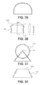
- FIGS. 39-40 illustrate variations of a tissue modification device having a center cable.
- FIGS. 41-42 illustrate variations of a rung of a tissue modification device.
- FIG. 43A-F illustrate one variation of a system including tools for treating spinal stenosis.
- This system includes two variations of a guidewire positioning probe tool ( 43 A and 43 B), a flexible neural localization tool ( 43 C), a tissue modification device ( 43 D), a removable guidewire handle ( 43 E), and a guidewire ( 43 F).
- FIGS. 44A-E illustrates one variation of a tissue modification device being inserted into the tissue and manipulated to modify the tissue. Tools such as those shown in FIG. 43A-43F may be used for this procedure.
- tissue modification devices and systems are provided herein.
- a flexible tissue-modification device as described herein is configured to remove tissue from a patient.
- these tissue-modification devices may be configured to decompress spinal stenosis.
- These devices typically include a flexible elongate body that extends proximally to distally (proximal/distal), and is configured to be inserted into a patient so that it extends around the target tissue, so that it can be bimanually pulled against the target tissue by applying tension to either end of the device.
- the device may be extended into, through, and/or around a spinal foramen.
- the device is flexible in at least one plane.
- the device in variations in which the device has an elongated ribbon shape that is long and flat with a width greater than the thickness, the device includes a first major surface (e.g., a front) and a second major surface (a back), and has edges (minor surfaces) between the first and second major surfaces.
- the first major surface may be referred to as the anterior or front surface and the second major surface may be referred to as the posterior or back surface.
- the devices described herein may be flexible along the anterior and posterior surfaces, and the anterior or front surface may include one or more cutting edges configured to cut tissue as the anterior surface of the device is urged against a tissue.
- the posterior surface may be configured to shield or protect non-target tissue.
- tissue modification devices described herein also typically include one or more of the following features: all or a portion of the device maybe formed of flexibly connected rungs or links; the devices may include a tissue capture region having a fixed minimum volume; and the device may be configured so that the major/minor surfaces may have non-linear shapes along their length, or may be stitched between linear and non-linear shapes.
- a tissue modification device may include one or more of these features in any combination. Each of these features is described and illustrated in greater detail below.
- devices, systems and methods of the present invention may be used in any of a number of other anatomical locations in a patient's body.
- the flexible tissue modification devices of the present invention may be used in minimally invasive procedures in the shoulder, elbow, wrist, hand, hip, knee, foot, ankle, other joints, or other anatomical locations in the body.
- some embodiments may be used to remove or otherwise modify ligamentum flavum and/or bone in a spine to treat spinal stenosis
- other tissues may be modified to treat any of a number of other conditions.
- treated tissues may include but are not limited to ligament, tendon, bone, tumor, cyst, cartilage, scar, osteophyte, inflammatory tissue and the like.
- Non-target tissues may include neural tissue and/or neurovascular tissue in some embodiments or any of a number of other tissues and/or structures in other embodiments.
- a flexible tissue modification device may be used to incise a transverse carpal ligament in a wrist while inhibiting damage to the median nerve, to perform a minimally invasive carpal tunnel release procedure.
- various embodiments described herein may be used to modify any of a number of different tissues, in any of a number of anatomical locations in the body, to treat any of a number of different conditions.
- a tissue modification device is formed from a plurality of flexibly connected rungs.
- a rung may also be referred to as a link or crosspiece.
- a rung may be stiff (e.g., made of a relatively rigid material) or flexible.
- the rungs may be connected to or may form the anterior (front) major surface. At least some of these rungs include one or more cutting edges, which may be configured as blades. The cutting edges may be formed as part of the rung, or attached to the rung.
- Individual rungs may have any appropriate shape.
- a rung may have a rectangular shape, an oval shape, a trapezoidal shape, or the like.
- the rung is relatively flat (e.g., having a thickness that is substantially less than the length and width).
- a rung may be smooth, rough or some combination. Different rungs in the same device may be different shapes and sizes, as illustrated below.
- a rung may be directly or indirectly connected to adjacent rungs.
- rung 2001 has a cambered shape.
- the cambered rung may be sized and configured to cut a swath of tissue 2002 , for example, that may be wider than a swath of tissue cut by a non-curved rung.
- the cambered rung may be sized and configured to cut a swath of ligament or other flexible and/or soft tissues.
- the flexible and/or soft tissue may be ligamentum flavum in a spine of a patient.
- the cambered rung may be sized and configured such that, as shown in FIG.
- a concave portion 2003 of the rung contacts the tissue such that the tissue may bunch or collect within the space defined by the concave portion of the cambered rung. Due to the bunching of the tissue, cutting edges 2004 (as described below) coupled to the rung (particularly, cutting edges toward the side edges of the rung) may contact the tissue at points further apart than blades on anon-curved rung may contact the tissue, thereby cutting a wider swath of tissue.
- the cambered rung may be sized and configured such that, as shown in FIG. 20B , a convex portion 2005 of the rung contacts the tissue such that the tissue may be pushed apart by or stretched over the convex portion of the cambered rung.
- a cambered rung 2101 may have cutting edges 2102 coupled to the rung toward the center of the rung in addition to or in alternative to cutting edges 2103 coupled to the rung toward the side edges of the rung.
- the cutting edges may be hook-shaped as described in more detail below.
- the rung may have a “U” shape (e.g. a rounded or a squared off U-shape).
- the rung may include two leg portions 2201 and a base portion 2202 .
- the leg portions may be perpendicular to the base portion, or may be configured in any other suitable fashion.
- the leg portions may be substantially straight, or may have a curved configuration
- the rung may define an opening 2204 through which a cable 2205 or other connector may be threaded.
- the rung may include a cutting edge 2203 . The cutting edge may be coupled to the leg portions of the rung above the opening 2204 . As shown in FIG.
- the U-shaped rungs may function to allow the legs of the rungs to pass through soft tissue 2208 , such as ligament, as the cutting edges cut through the tissue, such that the base portion of the rung does not catch on the tissue or otherwise obstruct the cutting of the tissue.
- a number of U-shaped rungs may be coupled to a cable to form a modification device.
- spacers 2206 may be coupled to the cable between two adjacent U-shaped rungs.
- the spacers 2206 may include a cutting edge 2207 .
- the leg portions may be flexible. As shown in FIGS.
- the leg portion 2301 of the U-shaped rung may be made from an expandable or stretchable material, such that as the cutting edge 2302 cuts through a tissue, the cutting edges and leg portions may extend further into the tissue ( FIG. 23B ), while the base portion 2302 remains on the surface of the tissue and does not catch on the tissue or otherwise obstruct the cutting of the tissue.
- Rungs are flexibly connected to adjacent rungs and/or to another portion of the tissue modification device.
- a connector such as a cable, wire, chain, string, sheet, ribbon, mesh, fabric, or the like, may be used to connect adjacent rungs.
- the connector may be flexible, or stiff.
- a connector may extend only between adjacent rungs, or it may extend along all or a portion of the length of the device so that multiple rungs may be attached to the same connector. More than one connector may be used to connect adjacent rungs. For example, as shown in FIGS. 24A-F , mugs may be connected between two parallel wires. As shown in FIGS.
- the rungs may be coupled to two parallel wires such that each rung is touching, or close to touching an adjacent rung, such that there are substantially no gaps between adjacent rungs.
- the edges of the rungs are rounded such that, as the device flexes and bends, the adjacent rungs can fold or bend against one another and/or articulate relative to one another.
- the rungs spaced in this manner i.e. such that the spacing between the rungs is reduced, and/or there are no gaps between the rungs, may function to reduce the risk of the edges of the rungs from tearing the soft tissue.
- the rungs spaced in this manner may allow the rungs to move over the soft tissue without tearing it, and may allow the cutting edges, coupled to the rungs, to cut the soft tissue.
- the rungs are directly connected to adjacent rungs by a hinge joint or the like. Combinations of connectors and direct connections between rungs may be used.
- rungs may be separated from each other by a space. The space may be an opening.
- one or more spacers are used to separate adjacent rungs. The spacing between adjacent rungs may be different.
- the spaces between rungs may provide a passage (or via) between the cutting surface on the anterior-facing surface of the rung, on which a cutting edge may be located (or may extend from) and the tissue collection region.
- FIG. 2A illustrates one variation of a tissue modification device having a plurality of rungs.
- FIG. 2A is a partially exploded, perspective view illustrating enlargements of various regions.
- the tissue-modification device shown in FIG. 2A is flexible and includes individual rungs that may articulate relative to each other.
- This device includes two parallel cables 201 , 201 ′ and a plurality of rungs 205 , 205 ′, 206 , 203 extend between the cables.
- the cables are the connectors that link adjacent rungs.
- the two cables are joined at the proximal 233 and distal 235 regions.
- the cable is joined at the proximal and distal ends, or is formed from a single cable; in some variations the two cables are separate. At least a portion of the cable is flexible. Any appropriate cable may be used, including metal or polymeric cables. Cables may be single-filament or formed of multiple filaments. The portion of the cable towards the distal end of the device, as shown in this example, may be hinged, and the links between distal and proximal sections may be connected in flexible junctions.
- FIG. 24A illustrates another variation of a tissue modification device having a plurality of rungs.
- the tissue-modification device shown in FIG. 24A is flexible and includes individual rungs that may articulate relative to each other. This device includes two parallel cables and a plurality of rungs 2401 , 2402 , 2403 , 2404 , 2405 , 2406 , 2407 , for example, that extend between the cables.
- the links or rungs 205 , 205 ′, 206 , 203 spanning the cables have different shapes and sizes.
- the rungs 203 in the central region each include one or more cutting edges 211 projecting from the anterior (target tissue facing) surface. These cutting rungs 203 may form a tissue modifying region of the device.
- the cutting edges shown are triangular or pointed, although any appropriate shape may be used. Further, these cutting edges may be oriented in any desired manner; the orientation of the cutting edges may help steer or guide the device as it is urged against a target tissue to cut the tissue. In this example the cutting edges are oriented in parallel with the long axis (the distal/proximal axis) of the device.
- the cutting edged may be angled inward toward the longitudinal center of the modification device.
- each rung may have cutting edges with the same orientation, or each rung may have a different orientation or an alternating orientation.
- an adjacent pair of rungs may have cutting edges that are angled in opposite directions, such that the cutting edges are oriented or angled toward a center point.
- the angled cutting edges may be sized and configured to guide or collect tissue toward the center point. More specifically, in some embodiments, the angled cutting edges may be sized and configured to guide or collect ligament or other flexible and/or soft tissues.
- the flexible and/or soft tissue may be ligamentum flavum in a spine of a patient.
- the cutting edges may have one of several suitable shapes and sizes, or any combination of shapes and sizes.
- the cutting edges and/or the rungs of the tissue modification device are configured to cut soft tissue, such as ligament.
- the cutting edges may function to cut the ligament rather than to tear and/or shred it.
- the cutting edges may have serrated edges ( FIG. 26 ), skate edges ( FIG. 27 ), “shark-tooth” shaped edges ( FIG. 28 ), “tombstone” shaped edges ( FIG. 29 ), hatchet shaped edges ( FIG. 30 ), roller edges ( FIG. 31 ), and/or any other suitable cutting edge configuration or shape.
- a serrated edge includes several smaller edges around a portion of the cutting edge.
- the cutting edge may include serrated portions along the sides 3201 of the cutting edge, while the top portion 3202 may not have serrated edges.
- the cutting edge may have a flat top portion, rather than a pointed top portion.
- a skate edge includes a curved portion of the blade oriented toward the cutting edge of the blade.
- a “shark-tooth” edge may also include a serrated edge, and may have a curved or hooked shape.
- a “tombstone” shaped edge may include a rounded edge. In some embodiments, the heights of the “tombstone” shaped edge vary from rung to rung.
- the variation shown in FIGS. 24A-F includes both rungs having a triangular (or other suitable shaped cutting edge) and rungs having tombstone shaped cutting edges.
- the tombstone shaped cutting edges are located toward the outer side or edge of the rung ( FIGS. 24D and 24F ), while the triangular shaped cutting edges may be located toward the center of the rung ( FIG. 24E ).
- the tombstone cutting edges may be sized and configured to cut a flexible and/or soft tissue, including ligament, such as ligamentum flavum in a patient's spine; while the triangular shaped cutting edges may be sized and configured to cut a rigid tissue, including bone, such as the bone of a facet joint, the bone that defines a central canal, and/or the bone that defines a neural foramen of a spine of a patient, including a pedicle.
- the tombstone cutting edges positioned toward the outer edges of the rung will cut a swath or strip of soft tissue. By positioning the cutting edge toward the outer edge of the rung, the cutting edge will cut an outline of the swath or strip into the soft tissue.
- a rung may include fixed bone cutting edges and soft tissue cutting edges that are flexible or foldable, such that they engage with tissue and/or pop up from the rung only as desired.
- the soft tissue cutting edges may be fixed while the bone cutting edges are movable.
- a cutting edge has a hatchet shape.
- the sides 3001 of the hatchet shaped cutting edge i.e. leading and trailing edges
- a top surface 3002 of the cutting edge may apply pressure to a tissue and cut it. For example, the top surface may apply pressure to a soft tissue against a bone to cut the soft tissue.
- the top edge of the blade may also act as a lead when traveling over the bone to avoid ratcheting of the modification device, for example to prevent a portion of the device (such as the rungs) from catching on tissue or otherwise.
- a portion of the rungs of the device may include hatchet shaped cutting edges 3301 , while a portion of the rungs may include tensioning cleats 3302 that function to pull and tension a soft tissue.
- the cleats are low profile and may have a blunt shape such as a blunt triangular shape or a blunt conical shape.
- the cleats are distal to the cutting edges, such that as the device is pulled distally across the target tissue, the cleats are pulled across the tissue first and may function to tension the tissue. The cutting edges may then be pulled across the tissue and cut the tensioned tissue.
- a modification device may have cutting edges on rungs toward the center of the device, and may have tensioning cleats on rungs toward the proximal and distal portion of the device. In this embodiment, the tissue may be tensioned as the device is pulled both distally and proximally. In FIG.
- the tension cleats are blunt on one side 3401 , and have a sharp, barbed, and/or hooked configuration 3402 on the opposite side, such that the opposite side of the cleat may function to couple to and remove tissue.
- the cleat may function to tension the tissue as the device is pulled distally, and then may function to couple to and remove the tissue as the device is pulled proximally.
- the cutting edges may be roller edges.
- the cutting edges may have an axel 3101 about which the cutting edge 3102 may rotate.
- the cutting edge may be circular, but may alternatively have other suitable shapes such as oval or polygonal, (e.g., a star shape).
- the axel may be coupled to a rung of the device.
- the cutting edge includes a raised platform 3501 .
- the raised platform is coupled to the rung 3502 toward one side of the rung such that it may angle up from the rung, as shown.
- the raised platform may include a first cutting edge 3503 and a second cutting edge 3504 .
- the first cutting edge is coupled to the top side of the raised platform, and in some embodiments, the second cutting edge is the exposed edge of the raised platform or may be coupled to the exposed edge or underside of the raised platform.
- the first cutting edge may be located toward the outer side or edge of the rung.
- the first cutting edge may be sized and configured to cut a flexible and/or soft tissue, such as ligament (e.g. ligamentum flavum in a patient's spine).
- the second cutting edge is sized and configured to scrape and/or remove tissue soft tissue cut by the first cutting edge.
- the first cutting edge may be oriented towards the distal end of the tissue modification device, such that, for example, as the device is pulled into a patient, and/or toward a target anatomy, the first cutting edge cuts the target tissue.
- the second cutting edge is oriented towards the proximal end of the tissue modification device, such that, for example, as the device is pulled out of a patient, and/or away from target anatomy, the second cutting edge may contact and/or engage with the swath of tissue, and pull the swath of tissue along with the device.
- the cutting edges may be hook-shaped.
- the hook-shaped cutting edges are sized and configured to couple to and remove a swath of tissue. More specifically, the hook-shaped cutting edges may be sized and configured to couple to and remove a swath of ligament or other flexible and/or soft tissues.
- the cutting edges may be configured to remove ligamentum flavum in a patient's spine.
- the tips 3601 of the hook-shaped cutting edges are oriented towards the proximal end of the tissue modification device, such that, for example, as the device is pulled out of a patient, or away from target anatomy, the tips of the hooked-shaped cutting edges may couple to the swath of tissue, and pull the swath of tissue along with the device.
- the hooked-shaped cutting edges may contact and/or engage with the swath of tissue by piercing the tissue and hooking onto the tissue.
- a rung may include hook-shaped cutting edges toward the center of the rung and blade shaped (e.g. triangular or tombstone shaped) cutting edges toward the side or edge of the rung.
- the side edges function to cut a swath of tissue
- the hooked-shaped edges function to contact and/or engage with and remove that swath of tissue.
- a portion of the rungs may include hooked shaped cutting edges, while a portion of the rungs may have side edges.
- the hooked rungs and the blade rungs alternate, while in some embodiments, a portion of the device includes hooked rungs and a second portion of the device includes blade rungs.
- the device further includes a sheath that covers the cutting edges while the device is being introduced into a patient. Once the device has been introduced, and/or once a swath of tissue, for example, has been cut, the sheath may be removed, and the hook-shaped (or other suitable shaped) cutting edges may contact and/or engage with and remove the swath of tissue. In some embodiments, the sheath further functions to remove the cut tissue.
- the hook-shaped cutting edges may be flexible or foldable such that when they are pulled in a distal direction (toward a target tissue), they do not engage with the tissue, and alternatively, when they are pulled in a proximal direction (away from a target tissue), the hooks engage with the tissue, and may contact and/or engage with and remove the tissue.
- the hook-shaped cutting edges contacting and/or engaged with tissue may be pulled out of a patient, pulling along the tissue.
- a user may remove (by suction, irrigation, manually, etc.) the tissue from the hooks. The device may then be reinserted to cut and/or capture additional tissue.
- the tissue modification device may include cutting edges directly coupled to a cable, rather than including a rung with a cutting blade.
- the cable 3701 may include cutting elements 3702 such as beads, blades, wires, or other suitable cutting elements.
- the cutting elements may be crimped onto the wire or attached by other suitable methods.
- the cutting cables may cut tissue using an energy such as heat or radio frequency energy. The energy may function to desiccate and/or shrink the tissue, rather than cutting it.
- a portion of the device may include cutting cables, while a portion of the device includes rungs threaded onto cables (with or without cutting edges on the rungs).
- a tissue modification device may include rungs 3801 along a portion of the device, and may further include a cutting cable 3802 coupled to the rung portion of the device.
- the cutting cables may be coupled to a U-shaped rung.
- the U-shaped rung may function to allow the legs of the rungs to pass through soft tissue 2208 , such as ligament, as the cutting edges cut through the tissue, such that the base portion 2202 of the rung does not catch on the tissue or otherwise obstruct the cutting of the tissue.
- the U-shaped rung may further function to support the cutting cable, and prevent two parallel cables from approximating toward one another.
- spacers 2206 may be coupled to the cable between two adjacent U-shaped rungs.
- the spacers 2206 may include a cutting edge 2207 .
- the device may include a shield coupled to the cutting cables.
- the shield may be coupled to the cutting cables such that while the cables are adjacent to the target tissue, the shield protects the adjacent non-target tissue, such as neural tissue, and/or may collect the tissue cut by the cutting cable.
- the cutting cables function to slide distally and proximally within or over a substantially stationary shield.
- the shield may function to contact and/or engage with and remove a swath of tissue (for example, soft tissue such as ligament) cut by the cutting cables.
- the rungs may have varying widths along the length of the tissue modification device.
- the rungs toward the distal end of the device e.g. rungs 2401
- the rungs towards the proximal end of the device e.g. rungs 2404 , 2405 , and 2406
- the small width may be on the order of 1 to 6 mm
- the large width may be on the order of 6 to 8 mm.
- the width of the device may be approximately the width of the rungs in some variations.
- the cutting edges may have different heights on different rungs.
- the cutting edges on the rungs toward the center of the device 298 may have a first height
- the cutting edges on the rungs toward the proximal 299 and/or distal 299 ′ ends of the device may have a second height.
- the first height may be larger than the second height, allowing the device to cut first a shallow cut, and then a deeper cut as the device is pulled along against tissue.
- the cutting edges in this configuration may function to provide a smooth transition as the device is pulled along against tissue and the sequentially higher cutting edges begin to engage with the tissue.
- the second height may be larger than the first height.
- adjacent cutting edges may have different heights.
- a first set of cutting edges includes a cutting edge having a first height, a cutting edge having a second height, and a third cutting edge also having the first height.
- the second height is taller than the first height.
- a tissue modification device may include a second set of cutting edges having a third height.
- the third height may be taller than the second and/or first height.
- the first set of cutting edges may be distal to the second set of cutting edges.
- the cutting edges are formed from the material forming the rung, and the cutting edge (e.g., blade) is machined as part of the rung.
- a rung may have an initial thickness measuring the height of the rung and the blade. The material at this initial thickness is machined (or otherwise removed) to form a series of blades projecting from the surface of the rung.
- the cutting edges may be cut out of the surface of the rung, and bent out of the surface of the rung such that the cutting edge or blade is substantially perpendicular to the rung.
- the cutting edge may be cut by Wire EDM machining (Electrical Discharge Machining), or any other suitable process.
- the cutting edges or blades may be manufactured separately and connected to the rung.
- the rungs are threaded onto the cables by openings or channels formed in the rung.
- a tissue-modification device such as the one shown in FIG. 2A and 24 A may be formed by threading the various components (e.g., rungs, spacers, etc.) onto the cable(s) connecting them.
- a tissue collection region may be connected below the rungs.
- the rungs may be rings, or may include space for tissue collection or a tissue-collection region.
- crimping elements 272 , 272 ′ may also be threaded onto the cables by openings or channels formed in the crimping elements. Once in place, the elements may be crimped to the cable or fixed to the cable in any other suitable fashion, such as by welding.
- the crimping elements fixed to the cable function to hold the rungs and other various components in place, and may further function to avoid loading the proximal and/or distal portions and/or ends of the tissue modification device.
- the proximal portions of the tissue modification device includes a protector region, such as a solid material or covering element over the cables.
- the tissue modification device may have a solid proximal end protector region or portion 274 .
- This solid portion may be a polymer extrusion, or any other suitable material in any suitable configuration.
- FIG. 2D shows one variation of a tissue modification device having ramp regions 288 , 288 ′ at the proximal and distal portions of the tissue modification device.
- the ramp begins towards the proximal and/or distal ends of the device, at a height approximately flush with the device, and increase.
- the height may increase to approximately the height of any blades or cutting surfaces, or slightly higher.
- the height of the ramp increases to a height approximately equal to or just below the height of the blades.
- the ramp may function to provide a smooth transition as the device is pulled along against tissue and the cutting edges begin to engage with the tissue.
- the ramp may extend across multiple rungs, a single rung, or may be coupled to the cables of the device.
- the ramp may be a solid structure, or a ribbed structure (as shown in FIG. 2D ).
- Rungs 203 with cutting edges 211 may extend over a portion of the length of the device.
- the device may include two or more rungs with cutting edges or blades 203 (e.g., “cutting rungs”).
- these cutting rungs 203 are separated by a gap formed by spacing elements 209 between the rungs.
- These spacing elements are also attached to the connector 201 , 201 ′ that flexibly connects the rungs.
- the spacers are threaded on the two parallel cables.
- the sizes of the connectors and/or spacing elements 209 may be varied to change the spacing between the rungs, and also the longitudinal shape (curvature) of the device, as described in greater detail, below. As shown in FIG.
- a spacer 2408 may be integrated into the rung 2404 .
- the spacer may be sized and configured such that two adjacent rungs define a space 2409 between them (cable 2410 can be seen in the space 2409 between the adjacent rungs).
- linking rungs 205 , 205 ′ may be used.
- distal linking rungs 205 are shown removed from the device, but may be included. These rungs may protect the cable, and/or the tissue, and may be different sizes.
- smaller rungs 206 may be used to house the cable or cables connecting the rungs. These rungs 206 may be shaped to allow the device to be flexible in one or more direction (e.g., up/down relative to the major surface), while limiting the flexibility in other directions.
- the cutting rungs, non-cutting rungs, spacing elements, or any other suitable portion of the device may include a tracking element.
- a tracking element may be disposed in the distal end of the device, such that the tip of the device may be tracked as it is inserted into a patient and/or moved within the patient.
- the device may include multiple tracking elements disposed along the length of the device, or multiple tracking elements disposed along a portion of the length of the device (for example along the cutting region of the device).
- the tracking element is a material that is detectable by an imaging system.
- suitable tracking elements include echogenic materials or substances (i.e.
- the tracking element may be configured to form an echogenic surface) detectable by an ultrasound system, and radio-opaque materials detectable by a radiograph system, such as a fluoroscope.
- the tracking element may be configured to be detectable by an MRI or Infrared system.
- the tracking element is preferably a coil configured to be detected by an electromagnetic tracking or navigation system.
- the devices described herein may incorporate a tracking system such as the AXIEMTM Electromagnetic Tracking Technology, e.g., the StealthStation® AXIEMTM (Medtronic Navigation, Louisville, Colo. USA).
- the device is configured to generate an electromagnetic field around a patient's target anatomy that can be tracked to triangulate the positioning of devices having tracking elements.
- the proximal end 233 of the device shown in FIG. 2A includes a handle 231 which may be permanently or removeably attached to the proximal end.
- the distal end 235 shown in FIG. 2A includes a guidewire coupler 237 that is flexibly attached to the distal end of the device.
- guidewire coupler 2411 is also flexibly attached to the distal end of the device.
- the guidewire coupler has a tapered shape such that it has a first width at the distal end and has a wider width toward the proximal end of the coupler.
- the proximal end of the coupler has substantially the same width as rungs 2401 .
- a guidewire coupler as shown in FIG. 24B may function to move (and thereby guide the trailing device) over, under, or around a soft tissue, such as ligament, rather than cutting or ripping through the tissue.
- a guidewire coupler is configured to attach to a guidewire (e.g., one end of a guidewire) so that the device can be manipulated, at least in part, by pulling on the guidewire after the guidewire has been secured to the device.
- a guidewire may be inserted into the body from a first location outside of the body, then passed around the target tissue (e.g., around a spinal foramen) and out of the body from a second position.
- the distal end of the guidewire may then be coupled to the flexible tissue modification device (such as the one shown in FIG. 2A ) and pulled through the body until the tissue modifying region of the device, e.g., the portion of the device including cutting rungs 203 , is positioned opposite the target tissue.
- the guidewire used includes a tip region that is enlarged and may engage the guidewire coupler.
- the guidewire may have a proximal end with a flange or ball. This enlarged region may be configured to fit into an opening on the guidewire coupler 242 so that the guidewire can be pulled distally from outside of the patient.
- the distal end of the device may be completely withdrawn, so that it can be grasped and manipulated.
- the distal end of the tissue-modification device remains coupled to the guidewire, and the guidewire may be grasped to manipulate the distal end of the tissue-modification device.
- a handle may be attached to the guidewire.
- the overall tissue-modification device shown in FIG. 2A has an elongate body formed of the plurality of substantially rigid rungs. This variation has a length (an axial length, from proximal to distal) and a width. The length of the device is longer than the width of each rung. In some embodiments, the ratio of the length of the device to the width of each rung is greater than five. Alternatively, in some embodiments, the ratio may be greater than ten. The device is also relatively thin; in this variation the thickness is smaller than the width of each rung. In some embodiments, the ratio of the width of each rung to the thickness of each rung is greater than two. Alternatively, in some embodiments, the ratio may be greater than five. The use of two cables for the device shown in FIG. 2A allows the articulation of the links.
- FIG. 3A illustrates one variation of the distal end of the tissue modification device in which the distal end includes a guidewire coupler 237 that is rotatably connected to the tissue modification device, more specifically to cable 201 , by connector 301 .
- the distal end, including a guidewire coupler may be rigidly attached to the cable, as shown in FIG. 3B .
- the distal ends of the cable include rungs 206 (as shown in FIG. 2A ), protector portion, or links that cover the cable, and may help prevent damage to tissue by presenting a relatively atraumatic surface.
- the flexible portion of the device formed by connected rungs or links is joined to the proximal end of the device, which may be less flexible, and may include a handle or an attachment region for a handle.
- This interface between the links forming the flexible region and the proximal end is shown as joint 252 .
- the proximal joint 252 near the proximal end 233 is a ball joint 207 to which the cables are attached.
- the ball joint allows the rotation of the handle and/or proximal portion of the device with respect to the tissue modification region of the device.
- the proximal handle may be rotated along the long axis of the tissue modification device, but will not substantially torque the tissue modification region of the device.
- the variation shown in FIG. 2A may also include a proximal connecting region 262 near the proximal end 233 of the device to which the handle 231 is attached.
- This connecting region may be relatively stiff (or inflexible), or it may also be flexible.
- the device is urged against the target tissue and may be moved in the proximal/distal direction to modify (e.g., cut) the target tissue.
- both the proximal and distal ends of the tissue-modification device may be pulled to urge the device against the target tissue, and may each be alternately pulled to a greater degree than the other handle to slide the device over the target tissue, allowing the cutting edges to cut and modify the target tissue.
- the blade(s) cut the tissue a moment is generated between the tip of the blade and the base of the blade, on the rung, where the cable runs through the rung.
- the base of the blade rung must be sufficiently wide to resist rotating about the length of the cable.
- a portion of a rung may contact the target tissue, while a second portion of the rung may not. Furthermore, a portion of a rung may contact the target tissue with a larger pressure than a second portion of the rung. It may be advantageous to maintain a substantially equal pressure and or substantially equal contact across the width of a rung. This may be achieved in one of several ways.
- the rungs may be flexible or jointed. In this embodiment, as the device is urged against the target tissue, the rungs may function to conform across their width around the target tissue, and thereby maintain a substantially equal pressure and or substantially equal contact across the width of a rung.
- the rungs 3901 are coupled to a single load bearing cable 3902 , running longitudinally along the device, coupled toward the center of the device, such that the rungs may rotate about the center cable, and thereby maintain a substantially equal pressure and or substantially equal contact across the width of a rung.
- the rungs of the tissue modification device will be maintained substantially parallel and/or flush to the plane of soft tissue (e.g. ligamentum flavum), preventing the device from preferentially cutting on one side.
- soft tissue e.g. ligamentum flavum
- the device can slide under the soft tissue rather than cutting a swath or strip of tissue, thereby potentially leaving target soft tissue behind after the procedure, which may be undesirable. As shown in FIG.
- the rung may include a channel or opening 3903 toward the center of the rung such that the rungs can be threaded onto a load bearing cable through the opening or channel formed in the center of the rung.
- the rung may include more than a single load bearing cable toward the center of the width of the device.
- the rung 4001 may include openings 4002 toward the sides of the rung in addition to the center opening 4003 .
- the rungs may be threaded onto additional side cables.
- the side cables may include spacers 4004 between the rungs as described above.
- the rung is held at a first height 4101 above a first cable and a second height 4102 above a second cable.
- the first height is greater than the second height, such that the rung is at an angle, and may thereby maintain a substantially equal pressure and or substantially equal contact across the width of a rung.
- the rung may include a channel or opening 4201 that is larger than the diameter of the cable 4202 onto which the rung is threaded. As shown, the rung may move on the cable such that it may maintain a substantially equal pressure and or substantially equal contact across the width of a rung.
- the cable(s) onto which the rungs are threaded remain lose prior to inserting the device into a patient.
- the cables may be tightened such that both sides of the rung contact the tissue and maintain a substantially equal pressure and or substantially equal contact across the width of a rung.
- the cables are tightened to different lengths.
- a larger force may be applied to a first cable than to a second cable.
- a larger force may be applied to the second cable than to the first cable.
- the cables are stretchable.
- a first cable may stretch to a length longer than the second cable such that both sides of the rung contact the tissue and maintain a substantially equal pressure and or substantially equal contact across the width of a rung.
- the cables and/or rungs may be made out of an elastic or shape memory material.
- the device may be inserted into a patient in a first configuration, and then once in portion, the device may shape change or reshape into a second configuration, wherein the second configuration is one that conforms to the target tissue, thereby maintaining a substantially equal pressure and or substantially equal contact across the width of a rung.
- the rungs forming the device may be flexibly connected by hinges between the rungs.
- the connections shown in FIG. 2A are flexible connections, and individual rungs are not directly connected, but are instead connected via a cable. Since the cable is flexible, the flexion point is concentrated between rung and mating ferrule (spacer).
- FIG. 4 shows a portion of a tissue modification device similar to that shown in FIG. 2A .
- the cutting rungs each include a plurality of cutting edges. These cutting edges are again shown as oriented along the long axis of the device, although other orientations may be used.
- the cutting edges may be offset from each other along the long axis of the device, so a wider cutting area is formed. Alternating adjacent rungs may have different cutting edge configurations such that the cutting edges may be offset from each other along the long axis of the device.
- a first rung may have cutting edges in configuration 2412 such that the position of the blades is biased toward a first side of the device (toward the top of FIG.
- a second rung may have cutting edges in configuration 2413 such that the position of the blades is biased toward a second side of the device (toward the bottom of FIG. 24A ), a third rung may have cutting edges in configuration 2412 such that the position of the blades is biased toward the first side of the device, and so on.
- FIG. 4 also illustrates spacers between each rung or link, on either side of the device (i.e., on each of the cables).
- different spacers are shown, including relatively long ferrules 401 , and bead-like spacers 403 .
- the different spacers may modify the flexibility of the device.
- FIG. 5A illustrates a portion of the proximal end of the tissue modification device shown in FIG. 2A in which the cables are attached to the joint 207 by coils 501 that permit the cables to flex during operation.
- these coils may be springs.
- the rungs forming the device may be flexibly connected by hinges between the rungs without spacers.
- the connections shown in FIG. 5B are flexible connections. Individual rungs are not directly connected, but are instead connected via a cable. Since the cable is flexible, the flexion point is concentrated between each rung. The length of each rung may be designed such that every transition point between each rung is a hinge point. As shown in FIG. 5B , the rungs may be configured such that a pair of rungs defines an opening between them. This opening may provide a location through which tissue may travel and/or be collected.
- a tissue-modification device may include flexibly connected rungs or links that do not require the connection by a proximal-distal cable illustrated in FIG. 2A .
- FIGS. 6-8A show various methods of flexibly connecting rungs or links.
- two adjacent cutting rungs are joined together so that they may move relative to each other as the device is flexed.
- the devices are hinged.
- FIGS. 7 and 8A illustrate alternative variations similar to FIG. 6 .
- the adjacent rungs or links are directly connected to each other and can be bent or moved as illustrated by the arrows. As shown in FIG.
- the devices can be bent (at least partially).
- the hinged region may be formed by bending two regions of the adjacent links over each other.
- a separate connector e.g., cable, etc.
- the hinged regions may include a hinge pin (not shown).
- FIGS. 9A-9D illustrate another alternative method of connecting adjacent rungs or links to allow flexion or provide flexibility.
- FIGS. 9A-9D show an embodiment in which adjacent links are connected via a woven ribbon to which the rungs are secured.
- a portion of flexible material is shown in FIG. 9A .
- Any appropriate (flexible) material including meshes, woven, non-woven, and polymeric materials may be used.
- the flexible material could be made from several materials, for example: stainless steel, aramid fibers, carbon fibers, glass fibers etc. Rungs can be attached to the flexible material by any appropriate method.
- FIG. 9A any appropriate (flexible) material, including meshes, woven, non-woven, and polymeric materials may be used.
- the flexible material could be made from several materials, for example: stainless steel, aramid fibers, carbon fibers, glass fibers etc.
- Rungs can be attached to the flexible material by any appropriate method.
- FIG. 9B shows a rung having downward-pointed edges configured to either pierce the woven ribbon or to be bent around the connector material, as illustrated in FIGS. 9C and 9D .
- the bottom side of the material and/or rungs can be softened by molding a polymer 904 to the material, as illustrated in FIG. 9H .
- the material may be formed into a ribbon or band shape. Additional rungs (of different or similar dimensions), may also be secured to the connector material forming the device.
- FIGS. 9E and 9F show another variation in which the downward-pointed edges of the rungs penetrate the material and pass through it so that they can be and secured to it.
- the downward pointing edges pierce the material (though the material may also include pre-formed holes). The downward-pointed regions can then be bent back up to secure the rung to the connector material. Other means for fastening the rung to the connector material may also be used.
- the edge of the rungs is not concurrent with the edge of the tissue-modification device.
- FIG. 9G shows a portion of an exemplary tissue-modification device including a flexible connector connecting multiple rungs having cutting edges extending from them.
- the rungs are spaced from the edge of the tissue cutting device, and an atraumatic edge 903 is included along the outer periphery (along the major surface).
- FIGS. 10 and 11 Spacing the rungs from the edge in this manner may reduce the risk of side cutting.
- the cable and rungs can be protected on the side by a separate tube like elements on the edges that are interlaced with the rungs and the cable, as illustrated in FIGS. 10 and 11 .
- the cables 1001 , 1001 ′ on either sides of the device are covered by a protective cover 1003 .
- Rungs 1005 span the distance between the two cables.
- FIG. 11 shows a slightly higher magnification of the tissue modification region of the device shown in FIG. 10 .
- the cutting edges 1101 are shown extending from the rungs.
- the blade rung “ladder” design described above for the tissue modification devices having flexibly linked rungs may include spaces between the rungs.
- the tissue cutting region may also include holes or openings. These spaces between the rungs, holes, and/or openings may form part of a tissue capture region, or may act as vias or channels to direct cut tissue into a tissue capture region.
- the tissue modification region modifies and/or removes the tissue, at least a portion of (and preferably the majority of) the cut tissue may be lodged between the cutting edges or blades and/or between the rungs of the device, such that the captured tissue is removed from the patient along with the device as the device is removed from the patient.
- the space between the rungs may channel cut tissue into a tissue capture region.
- the tissue may be driven into a tissue capturing or collection region.
- the edge of the adjacent rung may shear the tissue as the device is urged against the tissue and moved.
- the edge of the rung may also be sharp, or may include a sharp region.
- tissue may pass through the blade rungs and into a tissue collection region. The (typically upward) pressure of urging the device against the target tissue may therefore aide in packing the tissue into a tissue capture region.
- the device may have elements to aid in the movement of the cut tissue.
- the rungs may be designed such that two adjacent rungs function as a one way valve, allowing the tissue to enter through the space between the rungs, and then kept between or below the rungs and prevented from moving back out.
- Each rung may include a flap or a wing that couples to a flap or wing of an adjacent rung to function as a one way valve.
- the rungs may alternatively be designed in any other suitable fashion.
- a tissue capture region may require some amount of force or pressure to drive the cut tissue into the capture region. This may be particularly true for expandable tissue capture regions, such as an expandable bag that is attached behind the tissue modification region behind or within the rungs including cutting edges). As the tissue fills the area below the blades, the bag may expand to accommodate the increase volume. Increased pressure may be required to ‘pack’ the tissue into the tissue cutting region.
- tissue capture regions having a minimum volume that is fixed.
- the fixed minimum volume typically refers to a fixed open volume.
- Fixed minimum volume tissue capture regions typically include a minimum open volume, but this open volume may be increased as the device is operated; for example, the volume may be expandable from the fixed minimum open volume.
- the total volume of the tissue capture region maybe fixed or predetermined. Having a fixed minimum open volume allows tissue to enter the tissue capture region without having to apply additional force to drive the tissue into the tissue capture region.
- a tissue collection region having a fixed minimum open space may be defined by the space between the openings into the tissue collection region (which may be the rungs of the tissue modification region) and a tissue collection substrate.
- the tissue collection substrate is typically spaced apart from the tissue modification side of the rungs by a thickness that forms the open space.
- the tissue collection region may have a length that extends at least along the tissue modification region of the tissue modification device (e.g., the cutting rungs in variations including rungs), but may extend further proximally/distally.
- FIGS. 12A-12C illustrate one variation of a tissue modification device including a tissue collection region having a fixed minimum open space.
- FIG. 12A shows a cross-section along the tong (distal/proximal) axis of the device.
- the device includes a plurality of flexibly connected rungs 1205 that are connected by a connector (a cable 1215 ).
- the rungs in the tissue modification region include cutting edges 1209 .
- a tissue collection region 1219 (illustrated in FIG. 12B ) is formed between the top of the rungs 1205 and a tissue collection substrate 1211 .
- the tissue collection substrate 1211 is a semi-rigid substrate element that extends along the proximal/distal length of the device.
- the substrate element may additionally include guiding features to move and/or position the tissue in a desired direction, such as toward the outer portions of the device, beneath the non-cutting rungs.
- a guiding element may be one or more ridges in the substrate that are arrow or chevron shaped, with the vertex of the shape pointed toward the outer regions of the device.
- the distal end of this variation also includes a guidewire coupler or coupling region 1252 , and individual links 1205 may be separated by spacers (shown as ferrules) 1245 .
- FIG. 12B shows a cross-section through one of the rung elements 1205 shown in FIG. 12A .
- the rung 1205 includes two channels 1216 and 1216 ′ through which the cables 1215 ( FIG. 12A ) may pass.
- the top (anterior) of the rung includes a plurality of cutting edges 1209 .
- Within the rung 1205 is a fixed open volume 1219 that is formed between the top of the rung and a tissue collection substrate 1211 on the bottom of the rung.
- the tissue collection substrate may be secured within the rung by loops or straps 1223 that extend across the bottom of the rung.
- FIG. 12C shows a top view of the tissue modification device of FIGS. 12A and 12B .
- the tissue-collection substrate portion of the tissue modification device shown in FIGS. 12A-12C is slideable within the rungs (e.g., along the straps of the rungs).
- One end of the tissue collection substrate may be fixed (e.g., near the distal end of the device) and the other end may include an elastic or spring element 1272 that allows the tissue-collection substrate to slide as the tissue modification device is bent during operation.
- FIGS. 13A-13D illustrate variations of tissue-collection substrates that may be used.
- the tissue collection substrate 1211 is a semi-rigid sheet of material as shown in FIG. 12A-12C .
- the tissue-collection substrate may be formed of any appropriate material, including metals or alloys (e.g., stainless steel, titanium, NiTi, aluminum, etc.), plastics (e.g., PEAK, PET, PP, EP, PET, etc.), and elastic materials (e.g., urethanes, silicones, etc.). Other materials may also be used. Since the overall device (including the tissue collection substrate) is flexible at least in the plane forming the major surfaces, the tissue collection substrate may be bendable. Thus, when more rigid materials are used (e.g., metals) to form the substrate, the substrate may be relatively thin.
- metals or alloys e.g., stainless steel, titanium, NiTi, aluminum, etc.
- plastics e.g., PEAK, PET, PP, EP, PET, etc.
- elastic materials e.g., urethanes, silicones, etc.
- FIGS. 12D-12G illustrate another variation of a tissue modification device including a tissue collection region having a fixed minimum open space.
- FIG. 12D shows a perspective view of a portion of a tissue modification device including a tissue collection region 1262 .
- This tissue collection region has sides and a bottom region, and includes a channel through which connectors (shown as cables 1266 , 1266 ′ in FIG. 12D ) may pass.
- the tissue collection region may be a single, flexible piece, as indicated in FIG. 12D , or it may be a plurality of pieces linked by the connector.
- the tissue collection region also includes spaced into which rungs may fit so that the connectors may pass through the rungs. This is also apparent from the top view shown in FIG. 12E .
- FIGS. 12F and 12G illustrate sectional views taken through a portion of the tissue modification device including a cutting run (shown in FIG. 12F ) and a portion of the tissue modification device that is between adjacent cutting rungs (shown in FIG.
- the tissue collection region may include projections that project into a space or slot formed on the rungs; the connectors may pass through these projections and through the rungs.
- spacers e.g., ferrules, beads, etc.
- the substrate may be configured to expand/contract as the tissue modification device is flexed.
- the tissue collection substrate may be connected at one (or both) axial ends via a spring or elastic member.
- FIGS. 13 B 1 to 13 B 3 illustrate a side view of another variation of a substrate that is configured to accordion along its length as the device it is attached to is flexed.
- the substrate may contract or accordion closed, as shown in FIG. 13 B 1 .
- the substrate In the relaxed state the substrate is ‘neutral’, with folds that may be expanded or contracted, as shown in FIG. 13 B 2 .
- the tissue modification device is bent in a second direction the substrate may expand or accordion open, as shown in FIG. 13 B 3 .
- the substrate is expandable, and includes rigid edge with an expandable element between, as illustrated in FIG. 14A .
- the rigid portion may be secured to the tissue collection device (e.g., to the links of a tissue collection device), and the expandable portion may be made of a mesh or thin plastic material.
- FIG. 14B shows just the rigid portion of one variation of this embodiment, in which the rigid frame 1401 surrounding an expandable portion 1403 includes cross-struts 1407 . Substrates including expandable regions may be useful to allow the tissue collection region to expand even beyond the minimum fixed volume, allowing the collection of additional tissue even after the minimum fixed volume is filled.
- the tissue collection substrate may be held to the tissue modification device by one or more connectors linking the tissue collection substrate to the rung.
- the tissue collection region is bounded by the tissue collection substrate that is secured to the link via a strap or loop that is formed by the rung.
- the connectors are not part of the rungs, but are separate elements.
- FIGS. 15A-15C illustrate variations in which the tissue collection substrate is secured to the device by a cable or rod connector between each rung and the tissue collection substrate.
- the connector is formed as a part of the tissue collection substrate.
- FIG. 15A shows a cross-section through a flexible tissue modification device having rungs 1501 and a tissue collection region 1509 that is formed between the top of the rung 1501 and a substrate 1511 that is secured to the rung by a pair of cables 1515 , 1515 ′ or rods.
- FIG. 15C shows a similar variation in which the substrate is secured to the rung by connectors that may swing or slide. As described, the rung shown may be flexibly connected via one or more cables 1503 , 1503 ′.
- tissue collection regions there is a minimum open volume that has a fixed minimum, so that, even when flexed, the tissue collection region has a non-collapsible open space so that tissue can enter the space. In some variations this minimum fixed space is formed by a separation of between about 2 and about 6 mm between the rung forming the top of the space and the substrate.
- FIG. 15B shows a cross-section through the tissue modification region of a tissue modification device including rung and tissue collection design shown in FIG. 15A .
- the tissue collection substrate in this example is shown axially connected to the device via a spring 1511 .
- tissue cut by the blades may be collected into the tissue collection regions described.
- openings between the rungs may act as channels or vias through which cut tissue may pass into the collection region(s).
- the tissue modification device may include openings adjacent to the cutting edge(s) through which tissue may pass.
- tissue capturing mechanisms which may be used are described, for example, in U.S. Ser. No. 11/687,558 (titled “FLEXIBLE TISSUE REMOVAL DEVICES AND METHODS”), filed on Mar. 16, 2007, and U.S. Ser. No. 11/687,548 (titled “TISSUE REMOVAL WITH AT LEAST PARTIALLY FLEXIBLE DEVICES”), filed on Mar. 16, 2007, and U.S. Ser. No. 11/952,934 (titled “TISSUE REMOVAL DEVICES AND METHODS”), filed on Dec. 7, 2007; these references are all incorporated by reference herein.
- FIG. 16A to 16C illustrate one arrangement of cutting edges (blades) in which adjacent rungs have blades that are offset from each other. Offsetting the blade in this manner may allow them to more uniformly cut as the device is operated to modify tissue. Blade density may be important when it comes to cutting both soft tissue and bone. To improve the density and allow for material to pass through blade teeth, the leading and following blades may be interdigitated.
- FIGS. 16A-16C show the interdigitation of a set of blades. The first rung 1601 (Rung-A) cuts a leading path and the second rung 1603 (Rung-B) cuts a following path. This arrangement of cutting edges and rungs may help maximize the material removal for one cut stroke.
- FIG. 16C is a side view of Rung-A directly in front of Rung-B.
- any of these tissue-modification devices may also be configured to have a non-linear shape (e.g., axial shape) and/or be shape-morphing devices that can convert between linear and non-linear shapes.
- Non-linear devices may be pre-formed into a curved or bent shape (such as “s”-shaped, or serpentine, device or “c”-shaped devices, or the like).
- a non-linear device may be a shape-morphing device that can be changed from a linear to a non-linear shape, either before or during use of the device to modify tissue.
- linear and non-linear shapes typically refer to the shape of the device along the major (distal/proximal) axis, when looking down on the major (tissue-modifying) surface.
- FIG. 17A illustrates a device having S-shape (or serpentine) shape.
- This is a non-linear device (since the major surface does not travel in a line, but is curved).
- the device can be constructed using the cable (or wire) rung design, as illustrated in FIG. 18 .
- the links are separated by one or more spacers that are unequal in length from one side of the device (e.g., one cable) to the other. This difference in spacing causes the device to curve, as shown.
- the side of a device with a larger radius of curvature may include spacers such as relatively long ferrules 401 (shown in FIG.
- Curved devices may have a wider stroke length when cutting the tissue, and may therefore cut a wider region of tissue. For given stroke length, the amplitude (peak to peak of the curve) becomes the effective width of the device, producing a kerf wider than the individual rung.
- the devices can be deployed into the spine in a linear configuration and then changed to a non linear configuration.
- This conversion in shape may be achieved in-situ by pulling on a cable on one side of the rung more than the other side.
- the cable wire(s) could be locked in position near the proximal end and/or handle.
- the cables could be readjusted to form a linear shape to the device prior to device removal.
- a device may be increased in width by shift parallel links from an oblique angle to perpendicular with the cable, shown in the images below.
- the shape-morphing devices may be transitioned between a first straight (e.g., linear) configuration and a second straight configuration, with the first configuration being narrower than the second configuration.
- a first straight e.g., linear
- a second straight configuration with the first configuration being narrower than the second configuration.
- FIGS. 17B-17C and 17 D- 17 E Two examples of this are shown in FIGS. 17B-17C and 17 D- 17 E.
- the tissue modification device has a relatively narrow profile and can be expanded into a wider profile as illustrated in FIG. 17C .
- the rungs in 17 B are initially diagonal, relative to the parallel cables flexibly connecting them. By pulling on one of the cables, one side of the device to which the rungs are connected, may be pulled to align the rungs perpendicular to the long axis of the device. Since the rungs are relatively rigid, this will expand the width of the tissue modification device, as indicated in FIG. 17C .
- FIGS. 17D and 17E illustrate a similar variation, in which the tissue modification device may be expanded from a first linear configuration, in which the rungs are chevron-shaped when viewed from the top as in FIG. 17D , to a second linear configuration that is wider, in which the rungs can be pulled so that they are perpendicular to the long axis (proximal/distal axis) of the device, as illustrated in FIG. 17E .
- a cable, pull wire, or the like may be connected to the rungs to convert them from the first to the second shapes.
- the rungs may be adapted hinged) for conversion.
- each run is actually a two rungs that are joined end-to-end.
- any of the tissue modification devices described herein may be used to decompress one or more spinal regions, as mentioned above.
- any of these devices may be used to decompress nerve roots placed within the spinal anatomy along various paths, including those shown in FIGS. 19A-19C .
- these devices are flexible, and may be appropriately sized and shaped to fit within a neural foramen, these devices may be used to accesses appropriate regions of the spine from a single access point (e.g., from the patient's midline or near-midline region). The procedure may be used to decompress spinal nerve roots on the unilateral or bilateral side from the access point.
- a probe or guide may be introduced into the spinal epidural space (or along or just within the ligamentum flavum) at an appropriate spinal level using image guidance and/or tracking (e.g., electromagnetic tracking).
- image guidance and/or tracking e.g., electromagnetic tracking
- the device in which the probe or guide may be introduced just within the ligamentum flavum, the device may be used to cut a portion of the ligamentum flavum and in some cases may be used to cut a portion of the underlying bone, while leaving the surface of the ligamentum flavum intact. Introduction may be either via percutaneous puncture or open laminotomy.
- the device may be used to decompress an ipsilateral or contralateral proximal nerve (in a lateral recess).
- a guide may be deployed immediately cephalad to the caudal segment pedicle on the appropriate side (e.g., location 1810 ). This access point can be confirmed radiographically. If neural structures adjacent to the guide cannot be directly visualized, the relationship of these structures to the guide or tissue modification devices can be determined using electrical stimulation, ultrasound imaging, endoscopic mean or other techniques.
- a guidewire is passed via the cannulated guide. The guidewire can be sharp on its distal end and penetrate the skin dorsolaterally after exiting the foramen.
- the guidewire may include a wire exchange tip on its proximal end, as mentioned above. As shown in FIG. 19A , the guidewire may be threaded along a path from location 1810 to where it exits through the foramen, as shown by at least one of arrows 1812 (for ipsilateral decompression of the nerve root origin at the disk level) and 1814 (for contralateral decompression of the nerve root origin at the disk level). In some embodiments, the probe/guide is removed once the guidewire has been positioned.
- a flexible tissue modification device is attached to the proximal wire exchange tip, and a distal handle may be secured to the distal wire tip.
- the device can then be introduced into the epidural space and then into the lateral recess by careful upward force applied to the distal handle.
- the device is pulled by the guidewire on the path through the spinal anatomy.
- suitable paths include paths shown by arrows 1812 and 1814 to decompress the nerve root origin at disk level.
- bimanual reciprocating strokes may be utilized to decompress dorsal impinging bone or soft tissue at the nerve root origin. In some embodiments, approximately 30-40 reciprocating strokes are required to complete the decompression. This may be confirmed radiographically or with palpation by instruments.
- the device may then be detached and the wire removed.
- the probe/guide may be reinserted to decompress the ipsilateral or contralateral distal (foraminal) portion of the nerve root, so that the same (or a different) tissue modification device may be used to decompress another region of the spine (or nerve root) using the same access or entry site.
- a guide may be deployed immediately caudal to the caudal segment pedicle on the appropriate side.
- the guide may be deployed in the same access point (location 1810 ) as described above.
- Transforaminal positioning and the relationship to neural elements can again be confirmed visually, radiographically, and/or with electrical stimulation, ultrasound or alternative means. Once appropriate localization is confirmed, the guidewire can be passed and probe/guide removed. As shown in FIG.
- the guidewire may be threaded along a path from location 1810 to where it exits through the foramen, as shown by at least one of arrows 1816 (for ipsilateral decompression along the nerve root) and 1818 (for contralateral decompression along the nerve root).
- a handle is attached to the distal guidewire and the tissue modification device to the proximal exchange tip.
- the device is then introduced into the spine (e.g., the epidural space, or the region anterior to the posterior edge of the ligamentum flavum) with careful upward force applied to the distal handle.
- the device is pulled by the guidewire on the path through the spinal anatomy. As described above, and as shown in FIG.
- suitable paths include paths shown by arrows 1816 and 1818 to decompress along the nerve root.
- the foraminal decompression is performed using bimanual reciprocating strokes to remove impinging bone and soft tissue. In some embodiments, approximately 30-40 strokes are required to decompress the root. Confirmation of decompression may be done radiographically or using instruments to palpate along the root. The device can then be detached and the guidewire removed.
- the devices described herein can used to decompress the ipsilateral or contralateral (not shown), or both, regions adjacent the level proximal to the nerve root (lateral recess).
- a guide may be deployed in the same access point (location 1810 ) as described above. Transforaminal positioning and the relationship to neural elements are once again confirmed visually, radiographically, and/or with electrical stimulation, ultrasound or alternative means. Once appropriate localization is confirmed, the guidewire may be passed and the probe/guide removed. As shown in FIG. 19B , the guidewire can then be threaded along a path from location 210 to where it exits through the foramen, as shown by arrow 220 (for ipsilateral decompression of the adjacent nerve root origin).
- a handle can be attached to the distal guidewire and the guidewire can then be attached to the distal end of one of the tissue modification devices described herein.
- the device can then be introduced into the spine by pulling on the guidewire.
- the decompression device is pulled by the guidewire on the path through the spinal anatomy as illustrated in FIG. 19A , 19 B, or 19 C.
- suitable paths include the path shown by arrow 1820 the adjacent nerve root origin.
- the lateral recess decompression may be performed using bimanual reciprocating strokes to remove impinging bone and soft tissue. In some embodiments, approximately 30-40 strokes are required to decompress the nerve. Confirmation of decompression may be done radiographically or using instruments to palpate along the root.
- a probe/guide may be used to introduce a tissue modification device as described herein to decompress the central canal.
- the guide may be deployed in the same access point (location 1810 ) as described above. Once appropriate localization is confirmed, the guidewire may be passed and probe/guide removed. As shown in FIG. 5 , the guidewire can be threaded along a path from location 1810 to where it exits through the intralaminar window, as shown by arrow 1822 (not the adjacent foramen).
- a handle may be attached to the distal guidewire and, the tissue modification device may be coupled to the proximal end of the guidewire.
- the device can then be introduced into the epidural space by pulling the distal end of the guidewire on the path through the spinal anatomy, drawing the device into position adjacent the target tissue in the spinal canal.
- suitable paths include the path shown by arrow 1822 to decompress tissue associated with the central canal and may be effective in treating patients with central spinal stenosis.
- the decompression may be performed using bimanual reciprocating strokes to remove impinging bone and soft tissue. In some embodiments, approximately 30-40 strokes are required to decompress the root. Confirmation of decompression may be done radiographically or using instruments to palpate along the nerve.
- the probe, guide, or guidewire may also include a tracking element or plurality of tracking elements.
- the tracking element may be similar to the tracking element of the tissue modification device.
- the tracking element is a material that is detectable by an imaging system, while in some embodiments the tracking element is preferably a coil configured to be detected by an electromagnetic tracking or navigation system.
- any of the procedures described herein can be done in combination with other techniques including an open or minimally invasive decompression procedure where tools such as rongeurs and powered drills are used to remove tissue primarily around the proximal end of nerve root (lateral recess).
- tools such as rongeurs and powered drills are used to remove tissue primarily around the proximal end of nerve root (lateral recess).
- Such techniques may include laminotomies, etc.
- FIGS. 43A-F illustrate one variation of a system including one embodiments of the tissue modification device described above.
- Any of the tissue modification devices (and embodiments of these devices) described herein may be included in a system for treating spinal stenosis.
- the system includes two types of tools for positioning a guidewire ( 43 F), as shown in 43 A and 43 B.
- These tools are typically cannulated devices that may be used to position the guidewire around the target tissue.
- These cannulated tools may be steerable, or may have distal ends that are curved and/or extendable for steering the guidewire around the target tissue.
- the location of one or more nerves may be configured using a neural localization device (e.g., FIG.
- the neural localization device may include one or more electrodes for creating a localized electromagnetic field capable of stimulating only nearby nerves (thereby confirming they are adjacent to the pathway of the guidewire, or one or more sides of the guidewire pathway).
- the tissue modification device includes one or more neural localization devices.
- a handle may also be included, for attaching to the guidewire, better control of the guidewire. For example, in the system shown in FIGS. 43A-43F , the handle ( FIG. 43E ) is configured to connect to the guidewire ( FIG. 43F ), allowing the distal end of the guidewire to be pulled when the proximal end of the guidewire is coupled to the tool (e.g., the tissue modification device, FIG. 43D ).
- FIGS. 44A-44E illustrate one embodiment of a method for modifying tissue using one of the flexible tissue modification devices 10 described herein.
- a patient's skin, target tissue TT and non-target tissue NTT are shown diagrammatically, rather than as specific structures.
- the method of FIGS. 44A-44E may be employed in the spine, to remove ligamentum flavum, bone or both, with device 10 passing through an intervertebral foramen between two vertebrae.
- other tissue in other areas of the body may be removed.
- guidewire 22 with sharp tip 23 and shaped end 27 may be passed into the skin, between target and non-target tissue, and out of the skin.
- the guidewire may also be referred to a pullwire, since it is used to pull one or more devices into position, as described.
- Methods for passing guidewire/pullwire 22 are described further, for example, in U.S. patent application Ser. Nos. 11/457,416, 11/468,247 and 11/468,252, which were previously incorporated by reference.
- guidewire 22 may be placed using a percutaneous method, such as with a needle, or using an open method, such as with a probe.
- localization of neural tissue such as with nerve stimulation on a guidewire passing probe or guidewire passing guide member may be used, to confirm that guidewire 22 is passed between target and non-target tissue.
- a neural localization device as shown in FIG. 43C , above may be used by pulling into position using the guidewire/pullwire.
- one or more substances or devices may be placed into the epidural space of the spine before or after placing guidewire 22 , to create additional space between target tissues, such as ligamentum flavum, and non-target tissues, such as cauda equina and nerve root.
- Substances may include, for example, any of a number of fluids or gels, such as radiographic contrast medium.
- Devices may include, for example, a barrier or shield device. Injection of substances into the epidural space to create a safety zone is described in U.S.
- distal handle 24 (another variation of which is shown in FIG. 43E ) may be passed over sharp tip 23 and tightened around guidewire 22 , such as by moving tightening lever 25 .
- the handle captures or otherwise holds the sharp distal tip, to prevent injury or interference.
- Distal handle 24 may be coupled with guidewire 22 at this point in the process or at a later point, according to various embodiments.
- guidewire 22 may next be coupled with proximal device portion 11 , by coupling shaped guidewire end 27 (not visible) with guidewire coupler 18 .
- guidewire shaped end 27 may be placed into coupling member 18 (hollow-tipped arrow).
- distal handle 24 may then be pulled (hollow-tipped arrow) to pull device 10 into the patient and to thus position tissue modifying members 16 in contact with target tissue TT.
- a surgeon or other physician user may use tactile feedback of device 10 passing into the foramen, such as when coupling member 18 and/or tissue modifying members 16 pass into the foramen, to determine when tissue modifying members 16 are positioned in a desired location relative to target tissue TT.
- a surgeon may confirm that a desired placement has been achieved by using radiographic imaging, such as fluoroscopy, direct visualization, such as in an open surgical case, or a combination of multiple methods.
- device 10 may be passed into the patient and to a position for modifying tissue without removing any vertebral bone. More specifically, in some embodiments, device 10 may be advanced into the patient, through an intervertebral foramen, and out of the patient without removing bone. This is contrary to the majority of current surgical methods for treating spinal stenosis, which typically include removal of at least some vertebral bone, such as performing a laminotomy or laminectomy, and which often remove significant amounts of vertebral lamina, spinous process, facet and/or pedicle bony tissue, simply to access the surgical site. In one embodiment, for example, device 10 may be advanced percutaneously into the patient, used to remove ligamentum flavum only, and withdrawn from the patient, without removing any vertebral bone.
- tissue modifying members 16 e.g., rungs including tissue modification surfaces, as described above
- proximal handle 20 and guidewire handle 24 may be pulled (hollow-tipped arrows) to urge tissue modifying members 16 against target tissue TT (solid-tipped, single-headed arrows).
- handles 20 , 24 While maintaining pulling/tensioning force, handles 20 , 24 may be used to reciprocate device 10 back and forth (solid-tipped, double-headed arrows) to remove target tissue TT.
- the tissue modification device includes a rigid (or semi-rigid or rigidifiable) proximal shaft portion 13 that may be used to help steer device 10 , or more specifically flexible distal shaft portion 114 , relative to the target TT.
- a rigid shaft portion 113 may be used to move flexible portion 14 laterally or to pivot shaft 12 about an axis located along flexible portion 14 .
- rigid portion 13 may be used to manipulate flexible portion 14 within an intervertebral foramen, such as by pivoting shaft 12 or moving flexible portion 14 laterally in a caudal and/or cephalad direction, relative to the patient.
- the rigidity of rigid proximal shaft portion 13 may generally facilitate such steering, as compared to a completely flexible device.
- device 10 When a desired amount of tissue is removed, device 10 may be removed from the patient, such as by detaching guidewire handle 24 from guidewire 22 and pulling proximal handle 20 to withdraw device 10 and guidewire 22 out of the patient. In some embodiments, device 10 or an additional device may be reinserted into the patient and used in a second location to remove additional tissue. For example, in a spinal stenosis treatment procedure, device 10 may be used to remove tissue from (and thus decompress) a first intervertebral foramen and then my be removed and reinserted to remove tissue from a second foramen. This process may be repeated to remove tissue from any number of foramina.
- device 10 may include a guidewire lumen, so that a guidewire may be placed into a second foramen while device 10 is in the epidural space of the patient. Device 10 may then be removed along with the first guidewire 22 , attached to the second guidewire, and reinserted into the second foramen to remove tissue. In some embodiments, tissue may be removed from device 10 before reinserting device 10 into the patient to remove more tissue.
Landscapes
- Health & Medical Sciences (AREA)
- Surgery (AREA)
- Life Sciences & Earth Sciences (AREA)
- Medical Informatics (AREA)
- Animal Behavior & Ethology (AREA)
- Engineering & Computer Science (AREA)
- Biomedical Technology (AREA)
- Heart & Thoracic Surgery (AREA)
- Veterinary Medicine (AREA)
- Molecular Biology (AREA)
- Nuclear Medicine, Radiotherapy & Molecular Imaging (AREA)
- General Health & Medical Sciences (AREA)
- Public Health (AREA)
- Orthopedic Medicine & Surgery (AREA)
- Dentistry (AREA)
- Oral & Maxillofacial Surgery (AREA)
- Vascular Medicine (AREA)
- Surgical Instruments (AREA)
- Prostheses (AREA)
Abstract
Description
- This application is a continuation of International Patent Application No. PCT/US2009/050492, filed on Jul. 14, 2009, published as WO 2010/009093, which claims priority to U.S. Provisional Patent Application No. 61/080,647, filed on Jul. 14, 2008; U.S. Provisional Patent Application No. 61/081,685, filed on Jul. 17, 2008; and U.S. Provisional Patent Application 61/163,699, filed on Mar. 26, 2009, each of which are herein incorporated by reference in their entirety.
- This application is also a continuation-in-part of U.S. patent application Ser. No. 12/324,147, filed on Nov. 26, 2008, published as 2009/0149865, which claims priority to U.S. Provisional Patent Application No. 61/080,647, filed on Jul. 14, 2008 and U.S. Provisional Patent Application No. 61/081,685, filed on Jul. 17, 2008, each of which are herein incorporated by reference in their entirety.
- All publications and patent applications mentioned in this specification are herein incorporated by reference in their entirety as if each individual publication or patent application was specifically and individually indicated to be incorporated by reference.
- The present invention relates generally to medical/surgical devices and methods. More specifically, the present invention relates to flexible tissue modification devices and methods of modifying tissue using such devices, particularly for treatment of spinal stenosis.
- A significant number of surgical procedures involve modifying tissue in a patient's body, such as by removing, cutting, shaving, abrading, shrinking, ablating or otherwise modifying tissue. Minimally invasive (or “less invasive”) surgical procedures often involve modifying tissue through one or more small incisions or percutaneous access, and thus may be more technically challenging procedures. Some of the challenges of minimally invasive tissue modification procedures include working in a smaller operating field, working with smaller devices, and trying to operate with reduced or even no direct visualization of the tissue (or tissues) being modified. For example, using arthroscopic surgical techniques for repairing joints such as the knee or the shoulder, it may be quite challenging to modify certain tissues to achieve a desired result, due to the required small size of arthroscopic instruments, the confined surgical space of the joint, lack of direct visualization of the surgical space, and the like. It may be particularly challenging in some surgical procedures, for example, to cut or contour bone or ligamentous tissue with currently available minimally invasive tools and techniques. For example, trying to shave a thin slice of bone off a curved bony surface, using a small-diameter tool in a confined space with little or no ability to see the surface being cut, as may be required in some procedures, may be incredibly challenging or even impossible using currently available devices.
- One area of surgery which would likely benefit from the development of less invasive techniques is the treatment of spinal stenosis. Spinal stenosis occurs when nerve tissue and/or the blood vessels supplying nerve tissue in the spine become impinged by one or more structures pressing against them, causing symptoms. The most common form of spinal stenosis occurs in the lower (or lumbar) spine and can cause severe pain, numbness and/or loss of function in the lower back and/or one or both lower limb.
-
FIG. 1 is a top view of a vertebra with the cauda equina (the bundle of nerves that extends from the base of the spinal cord) shown in cross section and two nerve roots branching from the cauda equina to exit the central spinal canal and extend through intervertebral foramina on either side of the vertebra. Spinal stenosis can occur when the spinal cord, cauda equina and/or nerve root(s) are impinged by one or more tissues in the spine, such as buckled or thickened ligamentum flavum, hypertrophied facet joint (shown as superior articular processes inFIG. 1 ), osteophytes (or “bone spurs”) on vertebrae, spondylolisthesis (sliding of one vertebra relative to an adjacent vertebra), facet joint synovial cysts, and/or collapse, bulging or herniation of an intervertebral disc. Impingement of neural and/or neurovascular tissue in the spine by one or more of these tissues may cause pain, numbness and/or loss of strength or mobility in one or both of a patient's lower limbs and/or of the patient's back. - In the United States, spinal stenosis occurs with an incidence of between 4% and 6% (or more) of adults aged 50 and older and is the most frequent reason cited for back surgery in patients aged 60 and older. Patients suffering from spinal stenosis are typically first treated with conservative approaches such as exercise therapy, analgesics, anti-inflammatory medications, and epidural steroid injections. When these conservative treatment options fail and symptoms are severe, as is frequently the case, surgery may be required to remove impinging tissue and decompress the impinged nerve tissue.
- Lumbar spinal stenosis surgery involves first making an incision in the back and stripping muscles and supporting structures away from the spine to expose the posterior aspect of the vertebral column. Thickened ligamentum flavum is then exposed by complete or partial removal of the bony arch (lamina) covering the back of the spinal canal (laminectomy or laminotomy). In addition, the surgery often includes partial or complete facetectomy (removal of all or part of one or more facet joints), to remove impinging ligamentum flavum or bone tissue. Spinal stenosis surgery is performed under general anesthesia, and patients are usually admitted to the hospital for five to seven days after surgery, with full recovery from surgery requiring between six weeks and three months. Many patients need extended therapy at a rehabilitation facility to regain enough mobility to live independently.
- Removal of vertebral bone, as occurs in laminectomy and facetectomy, often leaves the affected area of the spine very unstable, leading to a need for an additional highly invasive fusion procedure that puts extra demands on the patient's vertebrae and limits the patient's ability to move. Unfortunately, a surgical spine fusion results in a loss of ability to move the fused section of the back, diminishing the patient's range of motion and causing stress on the discs and facet joints of adjacent vertebral segments. Such stress on adjacent vertebrae often leads to further dysfunction of the spine, back pain, lower leg weakness or pain, and/or other symptoms. Furthermore, using current surgical techniques, gaining sufficient access to the spine to perform a laminectomy, facetectomy and spinal fusion requires dissecting through a wide incision on the back and typically causes extensive muscle damage, leading to significant post-operative pain and lengthy rehabilitation. Thus, while laminectomy, facetectomy, and spinal fusion frequently improve symptoms of neural and neurovascular impingement in the short term, these procedures are highly invasive, diminish spinal function, drastically disrupt normal anatomy, and increase long-term morbidity above levels seen in untreated patients.
- Therefore, it would be desirable to have less invasive methods and devices for modifying target tissue in a spine to help ameliorate or treat spinal stenosis, while inhibiting unwanted damage to non-target tissues. Ideally, such techniques and devices would reduce neural and/or neurovascular impingement without removing significant amounts of vertebral bone, joint, or other spinal support structures, thereby avoiding the need for spinal fusion and, ideally, reducing the long-term morbidity resulting from currently available surgical treatments. Furthermore, such techniques may also remove both ligament and bone during spinal stenosis decompression. Such techniques could substantially cut ligament rather than substantially tearing, ripping, or shredding it, and remove ligament without leaving a substantial amount of target ligament present after the procedure. It may also be advantageous to have minimally invasive or less invasive tissue modification devices capable of treating target tissues in parts of the body other than the spine. At least some of these objectives will be met by the present invention.
- Described herein are improved devices for modifying tissue and methods of using them. These devices may be included as part of a system for modifying tissue. In general, these devices include a plurality of blades positioned on (or formed from) rungs that are flexibly connected. The rungs may be rigid, somewhat flat and wider than they are long (e.g., rectangular), or they may have other shapes. The rungs may be arranged, ladder like, to a flexible substrate, or to one or more cable(s). Different sized rungs may be used. The blades (on the rungs) may be arranged toward the side edges of the rungs and/or in a staggered arrangement. Any of the devices described herein may be used as part of a tissue decompression (e.g., spinal decompression) method to modify tissue such as soft tissue (e.g., ligamentum flavum, etc.) and hard tissue (e.g., bone). In particular, these devices may be used as part of a spinal decompression technique within a spinal foramen.
- In some variations, a tissue-collection or tissue capture element (e.g., chamber, bag, or the like) may be used to collect the cut or modified tissue.
- As mentioned, different shaped, or differently configured rungs may be used. For example, a single device may include two or more different kinds of cutting rungs (e.g., runs including cutting elements). In some variations, the devices may include two or more regions, in which each region has a different type of rung. For example, a rungs adapted for side cutting may be located proximally or distally to rungs adapted for cutting bone, or for cutting material perpendicular to the face of the device.
- In any of the variations described herein, the devices may include one or more spacers between individual rungs. The spacers may be rigid or flexible, and may be shaped. Shaping the spacers my help determine profile of the cutting surface, and may allow for tissue collection/capture between the rungs. Variations of spacers are described herein. A spacer may be attached to the same substrate (e.g., cable, mesh, etc.) to which the cutting rungs are attached.
- The devices described herein may be used as part of a guide-based access and decompression system, including those previously described in any of the following patent applications and provisional patent applications, each of which is herein incorporated by reference in its entirety: U.S. patent application Ser. No. 11/250,332, titled “DEVICES AND METHODS FOR SELECTIVE SURGICAL REMOVAL OF TISSUE” (filed Oct. 15, 2005), U.S. patent application Ser. No. 11/251,199, titled “DEVICES AND METHODS FOR TISSUE ACCESS” (Oct. 15, 2005), U.S. patent application Ser. No. 11/375,265, titled “METHODS AND APPARATUS FOR TISSUE MODIFICATION” (filed Mar. 13, 2006), U.S. patent application Ser. No. 11/405,848, titled “MECHANICAL TISSUE MODIFICATION DEVICES AND METHODS” (filed Apr. 17, 2006), U.S. patent application Ser. No. 11/429,377, titled “FLEXIBLE TISSUE RASP” (filed May 4, 2006), U.S. patent application Ser. No. 11/538,345, titled “ARTICULATING TISSUE CUTTING DEVICE” (filed Oct. 3, 2006), U.S. patent application Ser. No. 11/687,548, titled “TISSUE REMOVAL WITH AT LEAST PARTIALLY FLEXIBLE DEVICES” (filed Mar. 16, 2007), U.S. patent application Ser. No. 11/687,558, titled “FLEXIBLE TISSUE REMOVAL DEVICES AND METHODS” (filed Mar. 16, 2007), U.S. patent application Ser. No. 11/870,370, titled “PERCUTANEOUS SPINAL STENOSIS TREATMENT” (filed Oct. 10, 2007), and U.S. patent application Ser. No. 12/127,535, titled “GUIDEWIRE EXCHANGE SYSTEMS TO TREAT SPINAL STENOSIS” (filed May 27, 2008).
- In particular, the devices described herein may use a guidewire-based system that is configured so that the device may be pulled into position and/or tensioned so as to be urged against a tissue, and thereby modify the tissue. This configuration may be referred to as a bimanual system, since both ends (e.g., the proximal end and the distal end of the device) may be tensioned or pulled to modify the tissue. Tissue may be modified by removal or smoothing of the tissue, and may be performed by pulling the devices described herein through the tissue so that the working surface (e.g., the blades on the rungs) contacts one or more tissue surfaces.
- For example, described herein are flexible tissue-modification devices for removing tissue from a patient. These devices may have a flexible elongate body with an axial length, a width and a thickness, wherein the axial length is greater than the width and the width is greater than the thickness. These devices may also include: a connector extending longitudinally along the axial length of the device; a plurality of tissue-cutting rungs that are flexibly connected by the connector, wherein each rung extends at least partially across the width of the body; at least one cutting edge on each of the tissue-cutting rungs; and a plurality of spacers wherein each rung is separated from an adjacent rung by one or more spacers along the connector.
- Another variation of a flexible tissue-modification device for removing tissue from a patient includes: a proximal handle; a connector comprising at least two flexible elongate cables, wherein the cables extend substantially adjacent to each other from the proximal end region of the device to the distal end region of the device; a plurality of tissue-cutting rungs extending between the cables; a plurality of spacers wherein one or more spaces separates the tissue-cutting rungs; and at least one cutting edge on the tissue-cutting rungs, wherein the at least one cutting edge is sized and configured to cut soft tissue.
- These plurality of tissue-cutting rungs may include rungs of having different configurations and/or sizes. For example, the blades may be placed in different locations or have different shapes. The rungs may also be different shapes or sizes. In some variations the different rungs may be grouped together (to for a first region, a second region, etc.). Different rungs may interact with the tissue differently, leading to different ways of cutting and handling tissue of various types (e.g., soft tissue, bone, etc.).
- Any appropriate connector may be used. For example, the connector may be a at least one cable, a mesh or woven material, a hinged joint, or the like. The tissue-cutting rungs and spacers may be threaded on the connector.
- Any of these tissue modification devices may also include a guidewire coupler at the distal end of the device. In some variations, the devices include a protective side guard extending along the length of the flexible elongate body.
- In any of the variations described herein, the cutting edge may project from the surface of the rung. Any appropriate cutting edge, as described below, may be used.
- The devices may also include a tissue collection region in communication with the rung. In some variations, the tissue modification devices include at least one electrode configured for neural detection.
- Any appropriate spacer may be used. For example, the spacer may be configured to provide a passage between adjacent rungs. In some variations, the spacer is a ferrule.
- Also described herein are flexible tissue-modification device for removing tissue from a patient comprising: a flexible elongate body having a length, a width and a thickness, wherein the length is greater than the width and the width is greater than the thickness; an anterior surface extending proximally and distally across the width of the flexible elongate body; a plurality of cutting edges communicating with the anterior surface; wherein the flexible tissue-modification device is convertible from a first configuration, in which the anterior surface has a first proximal to distal shape, and a second configuration in which the anterior surface has a second proximal to distal shape; and a lock for locking the proximal to distal shape of the anterior surface of the tissue-modification device.
- In some variations, a flexible tissue-modification device for removing tissue from a patient, the device includes: a flexible elongate body having a length, a width and a thickness, wherein the length is greater than the width and the width is greater than the thickness; a plurality of rungs that are flexibly connected, wherein each rung extends across the width of the body and forms an anterior surface; at least one cutting edge on two or more of the rungs; wherein the flexible tissue-modification device is convertible from a first configuration, in which the anterior surface has a first proximal to distal shape, and a second configuration, in which the anterior surface has a second proximal to distal shape; and a lock for locking the proximal to distal shape of the anterior surface of the tissue-modification device.
- As mentioned, any of these devices may include a connector, such as a cable extending proximally and distally in the device and configured to change the shape of the proximal to distal shape of the anterior surface by applying tension to the cable.
- The first proximal to distal shape of the anterior surface may be linear. The second proximal to distal shape of the anterior surface may be curved. For example, the second proximal to distal shape may be a C-shape, an S-shape, etc.
- In addition, any of the devices described herein may include a guidewire coupler at the distal end of the flexible elongate body. Any of these devices may also include a handle or handle attachment region in communication with the proximal end of the flexible elongate body.
- As mentioned, the anterior surface of the device may include a plurality of flexibly connected rungs, wherein each rung extends across the width of the flexible elongate body. The device may also include a tissue collection region, such as a pouch, a bag, or the like. The tissue collection region may be expandable.
- Also described herein are flexible tissue-modification device for removing tissue from a patient, the device having a flexible elongate body with an axial length, a width and a thickness, wherein the axial length is greater than the width and the width is greater than the thickness, the device comprising: a proximal handle; a connector extending longitudinally along the axial length of the device; a first set of tissue-cutting rungs that are flexibly connected to the connector, wherein the first set of tissue-cutting rungs include at least one cutting edge positioned between the lateral edges of each rung; a second set of tissue-cutting rungs that are flexibly connected to the connector, wherein the second set of tissue-cutting rungs include at least one cutting edge positioned at a lateral edge of the rung; and a guidewire coupler at the distal end.
- One aspect of the devices described herein includes a flexible tissue-modification device for removing tissue from a patient. In some embodiments, the device includes a flexible elongate body having an axial length, a width and a thickness. The axial length is greater than the width and the width is greater than the thickness. The flexible elongate body includes a plurality of rungs that are flexibly connected and each rung extends at least partially across the width of the body. The device also includes at least one cutting edge on two or more of the rungs. The cutting edges are sized and configured to cut soft tissue.
- In some embodiments, the device for removing tissue from a patient includes at least two flexible elongate cables that extend substantially adjacent to each other from the proximal end of the device to the distal end of the device. The device also includes a plurality of rungs that each extend between the cables. The device also includes at least one cutting edge on two or more of the rungs. The cutting edges are sized and configured to cut soft tissue.
- The plurality of rungs may each have rounded edges along their length and may be connected such that a first rung is substantially contacting an adjacent rung along the length of the rung. The cutting edges may project from the surface of the rung. The cutting edge may project from the surface of the rung toward the outer edges of the rung and the cutting edge may be sized and configured to cut a strip of soft tissue and/or to cut an outline of the strip in the soft tissue. The cutting edge may include a serrated edge, a hooked shape, a concave curvature, a rounded convex curvature (e.g. a tombstone shaped edge). The cutting edge may be hatchet shaped or hook shaped. The cutting edge may be sized and configured to engage with soft tissue (e.g. ligamentum flavum) The rung may further include an axel about which the cutting edge may rotate.
- In some embodiments, the device further includes at least one tensioning cleat on two or more of the rungs. The tensioning cleat may be sized and configured to tension soft tissue (e.g. ligamentum flavum). In some embodiments, the device further includes at least one raised platform on two or more of the rungs. The raised platform may include a first cutting edge and a second cutting edge. The first cutting edge may be sized and configured to cut soft tissue, and the second cutting edge may be sized and configured to engage with soft tissue (e.g. ligamentum flavum).
- In some embodiments, two or more rungs include a base portion and at least two leg portions that define a U-shaped cross section. The leg portions may be flexible and/or have different lengths. The rung may define an opening sized and configured to receive a cable. The opening may be larger than the diameter than the cable. In some embodiments, two or more rungs have a cambered shape. The rung may be sized and configured to engage with a soft tissue such that the soft tissue bunches in the concave portion of the rung and the cutting edge may project from the surface of the concave portion of the rung. A hook shaped cutting edge may project from the surface of the concave portion of the rung, toward the center of the rung.
- The rung may be sized and configured to engage with a soft tissue such that the soft tissue is over the convex portion of the rung and the cutting edge may project from the surface of the convex portion of the rung. A hooked shaped cutting edge may project from the surface of the convex portion of the rung, toward the center of the rung.
- Another aspect of the devices described herein includes a flexible tissue-modification device for removing tissue from a patient. In some embodiments, the device includes at least two flexible elongate cables. The cables may extend substantially adjacent to each other from the proximal end of the device to the distal end of the device. The device further includes at least one cutting edge on at least one flexible elongate cable. In some embodiments, the cutting edge is crimped onto the cable. In some embodiments, the device further includes a plurality of rungs and each rung extends between the cables. The device may further include at least one cutting edge on two or more of the rungs. In some embodiments, the device further includes a second set of at least two flexible elongate cables. The second set of cables extend substantially in line with the first set of cables, and each rung extends between the second set of cables.
- Another aspect of the devices described herein includes a flexible tissue-modification device for removing tissue from a patient. In some embodiments, the device includes a flexible elongate body having an axial length, a width and a thickness. The axial length is greater than the width and the width is greater than the thickness. The device includes a flexible elongate center cable that extends from the proximal end of the device to the distal end of the device and the elongate body includes a plurality of rungs coupled to the cable. The cable is coupled to each rung toward the center of each rung, and each rung extends at least partially across the width of the body. The device also includes at least one cutting edge on two or more of the rungs.
- In some embodiments, the device also includes a second set of at least two flexible elongate cables, coupled to each rung at substantially the edge of each rung. The rungs may be sized and configured to rotate about the center cable such that the rungs maintain a substantially constant pressure against tissue across the surface of the rung. The rungs may be sized and configured to rotate about the center cable such that the rungs maintain a substantially constant contact with tissue across the surface of the rung.
-
FIG. 1 is a top view of a vertebra with the cauda equina shown in cross section and two nerve roots branching from the cauda equina to exit the central spinal canal and extend through intervertebral foramina on either side of the vertebra. -
FIG. 2A is a partially exploded, perspective view of a flexible tissue modification device including a plurality of flexibly connected rungs. -
FIG. 2B is a perspective view of another variation of a tissue modification device with progressively larger and smaller blades arranged along the length. -
FIG. 2C is another variation of a tissue modification device. -
FIG. 2D is another variation of a tissue modification device including two ramp regions. -
FIG. 3A shows one variation of a distal end of a tissue modification device, including a guidewire coupler. -
FIG. 3B shows another variation of the distal end of a tissue modification device, including a guidewire coupler. -
FIG. 4 shows a partial perspective view of a region of a tissue modification device. -
FIG. 5A is a partial perspective view of another region of a tissue modification device. -
FIG. 5B is a partial perspective view of another variation of a tissue modification device. -
FIG. 6 shows one variation of flexibly connected rungs of a tissue modification device. -
FIG. 7 shows another variation of flexibly connected rungs of a tissue modification device. -
FIG. 8A shows another variation of flexibly connected rungs of a tissue modification device, andFIG. 8B illustrates the bending of the flexibly connected rungs illustrated inFIG. 8A . -
FIG. 9A shows a flexible material that may be used as a connector to connect rungs forming a tissue modification device. -
FIG. 9B illustrate one variation of a rung that may be used with the connector shown inFIG. 9A .FIG. 9C illustrates the attachment of the rung ofFIG. 9B onto the material ofFIG. 9A , andFIG. 9D shows the rung assembled on the connector material. -
FIG. 9E shows an alternative attachment of the rung ofFIG. 9B onto a material such as the connector material ofFIG. 9A , andFIG. 9F shows a bottom view of the rung and connector assembly ofFIG. 9E . -
FIG. 9G is a partial perspective view of one variation of a tissue modification device. -
FIG. 9H is a side cross-section through the tissue modification device ofFIG. 9G . -
FIG. 10 is a bottom view of a tissue modification device including protective side covers. -
FIG. 11 is a top view of a tissue modification device including protective side covers. -
FIG. 12A is a side view of one variation of a tissue modification device including a fixed minimum open volume tissue collection region. -
FIG. 12B is a cross-sectional view through the tissue modification device ofFIG. 12A . -
FIG. 12C is a top view of the tissue modification device ofFIG. 12A . -
FIG. 12D shows a partial perspective view of a portion of a tissue modification device. -
FIG. 12E is a top view of the tissue collection region ofFIG. 12D . -
FIGS. 12F and 12G illustrate sections through the device shown inFIG. 12D . -
FIG. 13A shows one variation of a substrate of a tissue collection region such as the one shown inFIG. 12A-12C . - FIGS. 13B1-13B3 illustrate one variation of a substrate for a tissue collection region in which the substrate may accordion.
-
FIG. 14A shows another variation of a substrate for a tissue collection region having expandable regions and semi-rigid regions, andFIG. 14B is a top view of a semi-rigid frame for a tissue collection region such as the one inFIG. 14A . -
FIG. 15A is a cross-section through another tissue modification device having a fixed minimum open volume tissue collection region. -
FIG. 15B shows a partial side view of a tissue modification device having a fixed minimum open volume tissue collection region. -
FIG. 15C is a cross-section through another tissue modification device having a fixed minimum open volume tissue collection region. -
FIG. 16A shows perspective views of two adjacent rungs having alternating tissue cutting edges or blades, andFIG. 16B shows a side view of both of the two rungs illustrated inFIG. 16A . -
FIG. 16C shows a side view of the two rungs shown inFIGS. 16A and 16B when the two rung has been positioned adjacent to each other. -
FIG. 17A shows one variation of a tissue modification device having a non-linear axial shape. -
FIGS. 17B-17C illustrate one variation of a tissue modification device that may be expanded from a first, narrower, configuration (shown inFIG. 17B ), into a second, wider, configuration (shown inFIG. 17C ). -
FIGS. 17D-17E illustrate another variation of a tissue modification device that may be expanded from a first, narrower, configuration (shown inFIG. 17D ), into a second, wider, configuration (shown inFIG. 17E ). -
FIG. 18 is a partial perspective view of a flexible tissue modification device having a non-linear axial shape. -
FIG. 19A is a posterior view of the spine indicating decompression paths at disk level and along the nerve root. -
FIG. 19B is a posterior view of the spine indicating a decompression path for adjacent level lateral recess decompression. -
FIG. 19C is a posterior view of the spine indicating a decompression path for central canal decompression. -
FIGS. 20A-21 illustrate a variation of a rung of the tissue modification device having a curved shape. -
FIGS. 22A-22B illustrate a variation of a rung of the tissue modification device having a U-shaped cross section. -
FIGS. 23A-23B illustrate another variation of a rung of the tissue modification device having a U-shaped cross section. -
FIGS. 24A-F illustrate a variation of the tissue modification device. -
FIG. 25 illustrates a variation of rungs having angles cutting edges. -
FIGS. 26-32 illustrate variations of cutting edges of a tissue modification device. -
FIGS. 33-34 illustrate variations of cutting edges and tensioning cleats of a tissue modification device. -
FIG. 35 illustrates a rung of a tissue modification device having a raised platform. -
FIG. 36 illustrates a variation of a cutting edge. -
FIGS. 37-38 illustrate variations of a tissue modification device having a cutting cable. -
FIGS. 39-40 illustrate variations of a tissue modification device having a center cable. -
FIGS. 41-42 illustrate variations of a rung of a tissue modification device. -
FIG. 43A-F illustrate one variation of a system including tools for treating spinal stenosis. This system includes two variations of a guidewire positioning probe tool (43A and 43B), a flexible neural localization tool (43C), a tissue modification device (43D), a removable guidewire handle (43E), and a guidewire (43F). -
FIGS. 44A-E illustrates one variation of a tissue modification device being inserted into the tissue and manipulated to modify the tissue. Tools such as those shown inFIG. 43A-43F may be used for this procedure. - Various embodiments of tissue modification devices and systems, as well as methods for making and using tissue modification devices and systems, are provided herein. In general, a flexible tissue-modification device as described herein is configured to remove tissue from a patient. In particular, these tissue-modification devices may be configured to decompress spinal stenosis. These devices typically include a flexible elongate body that extends proximally to distally (proximal/distal), and is configured to be inserted into a patient so that it extends around the target tissue, so that it can be bimanually pulled against the target tissue by applying tension to either end of the device. Thus, the device may be extended into, through, and/or around a spinal foramen. The device is flexible in at least one plane. For example, in variations in which the device has an elongated ribbon shape that is long and flat with a width greater than the thickness, the device includes a first major surface (e.g., a front) and a second major surface (a back), and has edges (minor surfaces) between the first and second major surfaces. The first major surface may be referred to as the anterior or front surface and the second major surface may be referred to as the posterior or back surface. The devices described herein may be flexible along the anterior and posterior surfaces, and the anterior or front surface may include one or more cutting edges configured to cut tissue as the anterior surface of the device is urged against a tissue. The posterior surface may be configured to shield or protect non-target tissue.
- The tissue modification devices described herein also typically include one or more of the following features: all or a portion of the device maybe formed of flexibly connected rungs or links; the devices may include a tissue capture region having a fixed minimum volume; and the device may be configured so that the major/minor surfaces may have non-linear shapes along their length, or may be stitched between linear and non-linear shapes. A tissue modification device may include one or more of these features in any combination. Each of these features is described and illustrated in greater detail below.
- Although much of the following description and accompanying figures generally focuses on surgical procedures in spine, in alternative embodiments, devices, systems and methods of the present invention may be used in any of a number of other anatomical locations in a patient's body. For example, in some embodiments, the flexible tissue modification devices of the present invention may be used in minimally invasive procedures in the shoulder, elbow, wrist, hand, hip, knee, foot, ankle, other joints, or other anatomical locations in the body. Similarly, although some embodiments may be used to remove or otherwise modify ligamentum flavum and/or bone in a spine to treat spinal stenosis, alternative embodiments, other tissues may be modified to treat any of a number of other conditions. For example, in various embodiments, treated tissues may include but are not limited to ligament, tendon, bone, tumor, cyst, cartilage, scar, osteophyte, inflammatory tissue and the like. Non-target tissues may include neural tissue and/or neurovascular tissue in some embodiments or any of a number of other tissues and/or structures in other embodiments. In one alternative embodiment, for example, a flexible tissue modification device may be used to incise a transverse carpal ligament in a wrist while inhibiting damage to the median nerve, to perform a minimally invasive carpal tunnel release procedure. Thus, various embodiments described herein may be used to modify any of a number of different tissues, in any of a number of anatomical locations in the body, to treat any of a number of different conditions.
- In some variations, a tissue modification device is formed from a plurality of flexibly connected rungs. As used herein, a rung may also be referred to as a link or crosspiece. A rung may be stiff (e.g., made of a relatively rigid material) or flexible. The rungs may be connected to or may form the anterior (front) major surface. At least some of these rungs include one or more cutting edges, which may be configured as blades. The cutting edges may be formed as part of the rung, or attached to the rung.
- Individual rungs may have any appropriate shape. For example, a rung may have a rectangular shape, an oval shape, a trapezoidal shape, or the like. In general, the rung is relatively flat (e.g., having a thickness that is substantially less than the length and width). A rung may be smooth, rough or some combination. Different rungs in the same device may be different shapes and sizes, as illustrated below. A rung may be directly or indirectly connected to adjacent rungs.
- Some of the rungs may be curved. For example, as shown in
FIGS. 20A-20B ,rung 2001 has a cambered shape. In some embodiments, the cambered rung may be sized and configured to cut a swath oftissue 2002, for example, that may be wider than a swath of tissue cut by a non-curved rung. More specifically, the cambered rung may be sized and configured to cut a swath of ligament or other flexible and/or soft tissues. For example, the flexible and/or soft tissue may be ligamentum flavum in a spine of a patient. In some embodiments, the cambered rung may be sized and configured such that, as shown inFIG. 20A , aconcave portion 2003 of the rung contacts the tissue such that the tissue may bunch or collect within the space defined by the concave portion of the cambered rung. Due to the bunching of the tissue, cutting edges 2004 (as described below) coupled to the rung (particularly, cutting edges toward the side edges of the rung) may contact the tissue at points further apart than blades on anon-curved rung may contact the tissue, thereby cutting a wider swath of tissue. In some embodiments, the cambered rung may be sized and configured such that, as shown inFIG. 20B , aconvex portion 2005 of the rung contacts the tissue such that the tissue may be pushed apart by or stretched over the convex portion of the cambered rung. Due to the stretching of the tissue, cutting edges 2006 (as described below) coupled to the rung (particularly, cutting edges toward the side edges of the rung) may contact the tissue at points further apart than blades on a non-curved rung may contact the tissue, thereby cutting a wider swath of tissue. In some embodiments, as shown inFIG. 21 , acambered rung 2101 may have cuttingedges 2102 coupled to the rung toward the center of the rung in addition to or in alternative to cuttingedges 2103 coupled to the rung toward the side edges of the rung. The cutting edges may be hook-shaped as described in more detail below. - As shown in
FIG. 22A , the rung may have a “U” shape (e.g. a rounded or a squared off U-shape). The rung may include twoleg portions 2201 and abase portion 2202. The leg portions may be perpendicular to the base portion, or may be configured in any other suitable fashion. The leg portions may be substantially straight, or may have a curved configuration The rung may define anopening 2204 through which acable 2205 or other connector may be threaded. In some embodiments, the rung may include acutting edge 2203. The cutting edge may be coupled to the leg portions of the rung above theopening 2204. As shown inFIG. 22B , the U-shaped rungs may function to allow the legs of the rungs to pass throughsoft tissue 2208, such as ligament, as the cutting edges cut through the tissue, such that the base portion of the rung does not catch on the tissue or otherwise obstruct the cutting of the tissue. As shown, a number of U-shaped rungs may be coupled to a cable to form a modification device. In some embodiments,spacers 2206 may be coupled to the cable between two adjacent U-shaped rungs. Thespacers 2206 may include acutting edge 2207. In some embodiments, the leg portions may be flexible. As shown inFIGS. 23A-B , theleg portion 2301 of the U-shaped rung may be made from an expandable or stretchable material, such that as thecutting edge 2302 cuts through a tissue, the cutting edges and leg portions may extend further into the tissue (FIG. 23B ), while thebase portion 2302 remains on the surface of the tissue and does not catch on the tissue or otherwise obstruct the cutting of the tissue. - Rungs are flexibly connected to adjacent rungs and/or to another portion of the tissue modification device. A connector, such as a cable, wire, chain, string, sheet, ribbon, mesh, fabric, or the like, may be used to connect adjacent rungs. The connector may be flexible, or stiff. A connector may extend only between adjacent rungs, or it may extend along all or a portion of the length of the device so that multiple rungs may be attached to the same connector. More than one connector may be used to connect adjacent rungs. For example, as shown in
FIGS. 24A-F , mugs may be connected between two parallel wires. As shown inFIGS. 24B-C , the rungs may be coupled to two parallel wires such that each rung is touching, or close to touching an adjacent rung, such that there are substantially no gaps between adjacent rungs. In some embodiments, the edges of the rungs are rounded such that, as the device flexes and bends, the adjacent rungs can fold or bend against one another and/or articulate relative to one another. The rungs spaced in this manner (i.e. such that the spacing between the rungs is reduced, and/or there are no gaps between the rungs), may function to reduce the risk of the edges of the rungs from tearing the soft tissue. The rungs spaced in this manner may allow the rungs to move over the soft tissue without tearing it, and may allow the cutting edges, coupled to the rungs, to cut the soft tissue. In some variations, the rungs are directly connected to adjacent rungs by a hinge joint or the like. Combinations of connectors and direct connections between rungs may be used. In some variations, rungs may be separated from each other by a space. The space may be an opening. In some variations, one or more spacers are used to separate adjacent rungs. The spacing between adjacent rungs may be different. In variations including one or more tissue collection regions, the spaces between rungs may provide a passage (or via) between the cutting surface on the anterior-facing surface of the rung, on which a cutting edge may be located (or may extend from) and the tissue collection region. - For example,
FIG. 2A illustrates one variation of a tissue modification device having a plurality of rungs.FIG. 2A is a partially exploded, perspective view illustrating enlargements of various regions. The tissue-modification device shown inFIG. 2A is flexible and includes individual rungs that may articulate relative to each other. This device includes twoparallel cables rungs FIG. 24A illustrates another variation of a tissue modification device having a plurality of rungs. The tissue-modification device shown inFIG. 24A is flexible and includes individual rungs that may articulate relative to each other. This device includes two parallel cables and a plurality ofrungs - In some embodiments, the links or
rungs rungs 203 in the central region each include one ormore cutting edges 211 projecting from the anterior (target tissue facing) surface. These cuttingrungs 203 may form a tissue modifying region of the device. The cutting edges shown are triangular or pointed, although any appropriate shape may be used. Further, these cutting edges may be oriented in any desired manner; the orientation of the cutting edges may help steer or guide the device as it is urged against a target tissue to cut the tissue. In this example the cutting edges are oriented in parallel with the long axis (the distal/proximal axis) of the device. - In some embodiments, the cutting edged may be angled inward toward the longitudinal center of the modification device. In some embodiments, each rung may have cutting edges with the same orientation, or each rung may have a different orientation or an alternating orientation. For example, as shown in
FIG. 25 , an adjacent pair of rungs may have cutting edges that are angled in opposite directions, such that the cutting edges are oriented or angled toward a center point. In some embodiments, the angled cutting edges may be sized and configured to guide or collect tissue toward the center point. More specifically, in some embodiments, the angled cutting edges may be sized and configured to guide or collect ligament or other flexible and/or soft tissues. For example, in some embodiments, the flexible and/or soft tissue may be ligamentum flavum in a spine of a patient. - The cutting edges may have one of several suitable shapes and sizes, or any combination of shapes and sizes. In some embodiments, the cutting edges and/or the rungs of the tissue modification device are configured to cut soft tissue, such as ligament. The cutting edges may function to cut the ligament rather than to tear and/or shred it. The cutting edges may have serrated edges (
FIG. 26 ), skate edges (FIG. 27 ), “shark-tooth” shaped edges (FIG. 28 ), “tombstone” shaped edges (FIG. 29 ), hatchet shaped edges (FIG. 30 ), roller edges (FIG. 31 ), and/or any other suitable cutting edge configuration or shape. As shown inFIG. 26 , in some embodiments, a serrated edge includes several smaller edges around a portion of the cutting edge. As shown inFIG. 32 , for example, in some embodiments, the cutting edge may include serrated portions along thesides 3201 of the cutting edge, while thetop portion 3202 may not have serrated edges. InFIG. 32 , the cutting edge may have a flat top portion, rather than a pointed top portion. As shown inFIG. 27 , in some embodiments, a skate edge includes a curved portion of the blade oriented toward the cutting edge of the blade. As shown inFIG. 28 , a “shark-tooth” edge may also include a serrated edge, and may have a curved or hooked shape. A “tombstone” shaped edge may include a rounded edge. In some embodiments, the heights of the “tombstone” shaped edge vary from rung to rung. - The variation shown in
FIGS. 24A-F , includes both rungs having a triangular (or other suitable shaped cutting edge) and rungs having tombstone shaped cutting edges. In some embodiments, the tombstone shaped cutting edges are located toward the outer side or edge of the rung (FIGS. 24D and 24F ), while the triangular shaped cutting edges may be located toward the center of the rung (FIG. 24E ). For example, the tombstone cutting edges may be sized and configured to cut a flexible and/or soft tissue, including ligament, such as ligamentum flavum in a patient's spine; while the triangular shaped cutting edges may be sized and configured to cut a rigid tissue, including bone, such as the bone of a facet joint, the bone that defines a central canal, and/or the bone that defines a neural foramen of a spine of a patient, including a pedicle. The tombstone cutting edges positioned toward the outer edges of the rung, will cut a swath or strip of soft tissue. By positioning the cutting edge toward the outer edge of the rung, the cutting edge will cut an outline of the swath or strip into the soft tissue. A rung may include fixed bone cutting edges and soft tissue cutting edges that are flexible or foldable, such that they engage with tissue and/or pop up from the rung only as desired. Alternatively, the soft tissue cutting edges may be fixed while the bone cutting edges are movable. - In some embodiments, as shown in
FIG. 30 , a cutting edge has a hatchet shape. Thesides 3001 of the hatchet shaped cutting edge (i.e. leading and trailing edges), may function to hook into and slice a target tissue. More specifically, the sides of the cutting edge may function to hook into and slice a soft tissue, such as a ligament, such as a ligamentum flavum in a spine of a patient. Atop surface 3002 of the cutting edge may apply pressure to a tissue and cut it. For example, the top surface may apply pressure to a soft tissue against a bone to cut the soft tissue. The top edge of the blade may also act as a lead when traveling over the bone to avoid ratcheting of the modification device, for example to prevent a portion of the device (such as the rungs) from catching on tissue or otherwise. As shown inFIG. 33 , a portion of the rungs of the device may include hatchet shapedcutting edges 3301, while a portion of the rungs may include tensioningcleats 3302 that function to pull and tension a soft tissue. In some embodiments, the cleats are low profile and may have a blunt shape such as a blunt triangular shape or a blunt conical shape. In some embodiments, the cleats are distal to the cutting edges, such that as the device is pulled distally across the target tissue, the cleats are pulled across the tissue first and may function to tension the tissue. The cutting edges may then be pulled across the tissue and cut the tensioned tissue. A modification device may have cutting edges on rungs toward the center of the device, and may have tensioning cleats on rungs toward the proximal and distal portion of the device. In this embodiment, the tissue may be tensioned as the device is pulled both distally and proximally. InFIG. 34 , the tension cleats are blunt on oneside 3401, and have a sharp, barbed, and/or hookedconfiguration 3402 on the opposite side, such that the opposite side of the cleat may function to couple to and remove tissue. For example, the cleat may function to tension the tissue as the device is pulled distally, and then may function to couple to and remove the tissue as the device is pulled proximally. - In some embodiments, as shown in
FIG. 31 , the cutting edges may be roller edges. The cutting edges may have anaxel 3101 about which thecutting edge 3102 may rotate. The cutting edge may be circular, but may alternatively have other suitable shapes such as oval or polygonal, (e.g., a star shape). In some embodiments, the axel may be coupled to a rung of the device. - In the embodiments, shown in
FIG. 35 , the cutting edge includes a raisedplatform 3501. In some embodiments, the raised platform is coupled to therung 3502 toward one side of the rung such that it may angle up from the rung, as shown. The raised platform may include afirst cutting edge 3503 and asecond cutting edge 3504. In some embodiments, the first cutting edge is coupled to the top side of the raised platform, and in some embodiments, the second cutting edge is the exposed edge of the raised platform or may be coupled to the exposed edge or underside of the raised platform. The first cutting edge may be located toward the outer side or edge of the rung. - The first cutting edge may be sized and configured to cut a flexible and/or soft tissue, such as ligament (e.g. ligamentum flavum in a patient's spine). In some embodiments, the second cutting edge is sized and configured to scrape and/or remove tissue soft tissue cut by the first cutting edge. The first cutting edge may be oriented towards the distal end of the tissue modification device, such that, for example, as the device is pulled into a patient, and/or toward a target anatomy, the first cutting edge cuts the target tissue. In some embodiments, the second cutting edge is oriented towards the proximal end of the tissue modification device, such that, for example, as the device is pulled out of a patient, and/or away from target anatomy, the second cutting edge may contact and/or engage with the swath of tissue, and pull the swath of tissue along with the device.
- As shown in
FIG. 36 , the cutting edges may be hook-shaped. In some embodiments, the hook-shaped cutting edges are sized and configured to couple to and remove a swath of tissue. More specifically, the hook-shaped cutting edges may be sized and configured to couple to and remove a swath of ligament or other flexible and/or soft tissues. For example, the cutting edges may be configured to remove ligamentum flavum in a patient's spine. In some embodiments, the tips 3601 of the hook-shaped cutting edges are oriented towards the proximal end of the tissue modification device, such that, for example, as the device is pulled out of a patient, or away from target anatomy, the tips of the hooked-shaped cutting edges may couple to the swath of tissue, and pull the swath of tissue along with the device. In some embodiments, the hooked-shaped cutting edges may contact and/or engage with the swath of tissue by piercing the tissue and hooking onto the tissue. - A rung may include hook-shaped cutting edges toward the center of the rung and blade shaped (e.g. triangular or tombstone shaped) cutting edges toward the side or edge of the rung. In some embodiments, the side edges function to cut a swath of tissue, and the hooked-shaped edges function to contact and/or engage with and remove that swath of tissue. In some embodiments, a portion of the rungs may include hooked shaped cutting edges, while a portion of the rungs may have side edges. In some embodiments, the hooked rungs and the blade rungs alternate, while in some embodiments, a portion of the device includes hooked rungs and a second portion of the device includes blade rungs.
- In some embodiments, the device further includes a sheath that covers the cutting edges while the device is being introduced into a patient. Once the device has been introduced, and/or once a swath of tissue, for example, has been cut, the sheath may be removed, and the hook-shaped (or other suitable shaped) cutting edges may contact and/or engage with and remove the swath of tissue. In some embodiments, the sheath further functions to remove the cut tissue. The hook-shaped cutting edges may be flexible or foldable such that when they are pulled in a distal direction (toward a target tissue), they do not engage with the tissue, and alternatively, when they are pulled in a proximal direction (away from a target tissue), the hooks engage with the tissue, and may contact and/or engage with and remove the tissue. The hook-shaped cutting edges contacting and/or engaged with tissue may be pulled out of a patient, pulling along the tissue. In some embodiments, once outside of the patient, a user may remove (by suction, irrigation, manually, etc.) the tissue from the hooks. The device may then be reinserted to cut and/or capture additional tissue.
- The tissue modification device may include cutting edges directly coupled to a cable, rather than including a rung with a cutting blade. As shown in
FIG. 37 , thecable 3701 may include cuttingelements 3702 such as beads, blades, wires, or other suitable cutting elements. In some embodiments, the cutting elements may be crimped onto the wire or attached by other suitable methods. The cutting cables may cut tissue using an energy such as heat or radio frequency energy. The energy may function to desiccate and/or shrink the tissue, rather than cutting it. As shown inFIG. 37 , a portion of the device may include cutting cables, while a portion of the device includes rungs threaded onto cables (with or without cutting edges on the rungs). The cutting cables and the cables onto which the rungs are threaded may be the same or different cables. As shown inFIG. 38 , a tissue modification device may includerungs 3801 along a portion of the device, and may further include a cuttingcable 3802 coupled to the rung portion of the device. - As mentioned above in reference to
FIGS. 22A-B , the cutting cables may be coupled to a U-shaped rung. The U-shaped rung may function to allow the legs of the rungs to pass throughsoft tissue 2208, such as ligament, as the cutting edges cut through the tissue, such that thebase portion 2202 of the rung does not catch on the tissue or otherwise obstruct the cutting of the tissue. The U-shaped rung may further function to support the cutting cable, and prevent two parallel cables from approximating toward one another. In some embodiments,spacers 2206 may be coupled to the cable between two adjacent U-shaped rungs. Thespacers 2206 may include acutting edge 2207. - The device may include a shield coupled to the cutting cables. The shield may be coupled to the cutting cables such that while the cables are adjacent to the target tissue, the shield protects the adjacent non-target tissue, such as neural tissue, and/or may collect the tissue cut by the cutting cable. In some embodiments, the cutting cables function to slide distally and proximally within or over a substantially stationary shield. In some embodiments, the shield may function to contact and/or engage with and remove a swath of tissue (for example, soft tissue such as ligament) cut by the cutting cables.
- In some embodiments, the rungs may have varying widths along the length of the tissue modification device. For example, as shown in
FIG. 24A , the rungs toward the distal end of the device (e.g. rungs 2401) may have a small width, while rungs towards the proximal end of the device (e.g. rungs - In one variation, as shown in
FIG. 2B , the cutting edges may have different heights on different rungs. For example, inFIG. 2B the cutting edges on the rungs toward the center of thedevice 298 may have a first height, while the cutting edges on the rungs toward the proximal 299 and/or distal 299′ ends of the device may have a second height. The first height may be larger than the second height, allowing the device to cut first a shallow cut, and then a deeper cut as the device is pulled along against tissue. The cutting edges in this configuration may function to provide a smooth transition as the device is pulled along against tissue and the sequentially higher cutting edges begin to engage with the tissue. Alternatively, the second height may be larger than the first height. In some embodiments, as shown inFIG. 24 , adjacent cutting edges may have different heights. For example, inFIG. 24D a first set of cutting edges includes a cutting edge having a first height, a cutting edge having a second height, and a third cutting edge also having the first height. InFIG. 24D , the second height is taller than the first height. There may be any suitable number of adjacent cutting edges having each of either the first height or the second height, and in some variations, there may be a number of cutting edges having any other suitable height. As shown inFIG. 24F , a tissue modification device may include a second set of cutting edges having a third height. For example,FIG. 24A , the third height may be taller than the second and/or first height. In some embodiments (e.g.FIG. 24A ) the first set of cutting edges may be distal to the second set of cutting edges. - In some variations, the cutting edges are formed from the material forming the rung, and the cutting edge (e.g., blade) is machined as part of the rung. For example, a rung may have an initial thickness measuring the height of the rung and the blade. The material at this initial thickness is machined (or otherwise removed) to form a series of blades projecting from the surface of the rung. Alternatively, the cutting edges may be cut out of the surface of the rung, and bent out of the surface of the rung such that the cutting edge or blade is substantially perpendicular to the rung. The cutting edge may be cut by Wire EDM machining (Electrical Discharge Machining), or any other suitable process. In some embodiments, the cutting edges or blades may be manufactured separately and connected to the rung.
- In
FIGS. 2A and 24A the rungs are threaded onto the cables by openings or channels formed in the rung. For example, a tissue-modification device such as the one shown inFIG. 2A and 24A may be formed by threading the various components (e.g., rungs, spacers, etc.) onto the cable(s) connecting them. In some variations (described in greater detail below), a tissue collection region may be connected below the rungs. In some variations the rungs may be rings, or may include space for tissue collection or a tissue-collection region. - In some embodiments, as shown in
FIG. 2C , crimpingelements - The cables or rungs in one or more regions along the device may be covered or protected. For example, in
FIG. 2C , the proximal portions of the tissue modification device includes a protector region, such as a solid material or covering element over the cables. Thus, the tissue modification device may have a solid proximal end protector region orportion 274. This solid portion may be a polymer extrusion, or any other suitable material in any suitable configuration. - A widener or ramp region or regions may also be included as part of the tissue modification device. For example,
FIG. 2D shows one variation of a tissue modification device havingramp regions FIG. 2D ). -
Rungs 203 with cuttingedges 211 may extend over a portion of the length of the device. As illustrated inFIG. 2A , the device may include two or more rungs with cutting edges or blades 203 (e.g., “cutting rungs”). In this example, these cuttingrungs 203 are separated by a gap formed by spacingelements 209 between the rungs. These spacing elements are also attached to theconnector FIG. 2A the spacers are threaded on the two parallel cables. The sizes of the connectors and/orspacing elements 209 may be varied to change the spacing between the rungs, and also the longitudinal shape (curvature) of the device, as described in greater detail, below. As shown inFIG. 24D , in some embodiments, aspacer 2408 may be integrated into therung 2404. The spacer may be sized and configured such that two adjacent rungs define aspace 2409 between them (cable 2410 can be seen in thespace 2409 between the adjacent rungs). - Returning to
FIG. 2A , in addition to the cuttingrungs 203, other rungs may also be included that do not have a cutting surface. For example, linkingrungs FIG. 2A distal linkingrungs 205 are shown removed from the device, but may be included. These rungs may protect the cable, and/or the tissue, and may be different sizes. Nearer to thedistal end 235 of the device shown inFIG. 2A ,smaller rungs 206 may be used to house the cable or cables connecting the rungs. Theserungs 206 may be shaped to allow the device to be flexible in one or more direction (e.g., up/down relative to the major surface), while limiting the flexibility in other directions. - In some embodiments, the cutting rungs, non-cutting rungs, spacing elements, or any other suitable portion of the device may include a tracking element. For example, a tracking element may be disposed in the distal end of the device, such that the tip of the device may be tracked as it is inserted into a patient and/or moved within the patient. Alternatively, the device may include multiple tracking elements disposed along the length of the device, or multiple tracking elements disposed along a portion of the length of the device (for example along the cutting region of the device). In some embodiments, the tracking element is a material that is detectable by an imaging system. Some examples of suitable tracking elements include echogenic materials or substances (i.e. configured to form an echogenic surface) detectable by an ultrasound system, and radio-opaque materials detectable by a radiograph system, such as a fluoroscope. Alternatively, the tracking element may be configured to be detectable by an MRI or Infrared system. In some embodiments the tracking element is preferably a coil configured to be detected by an electromagnetic tracking or navigation system. For example, the devices described herein may incorporate a tracking system such as the AXIEM™ Electromagnetic Tracking Technology, e.g., the StealthStation® AXIEM™ (Medtronic Navigation, Louisville, Colo. USA). In some embodiments, the device is configured to generate an electromagnetic field around a patient's target anatomy that can be tracked to triangulate the positioning of devices having tracking elements.
- The
proximal end 233 of the device shown inFIG. 2A includes ahandle 231 which may be permanently or removeably attached to the proximal end. Thedistal end 235 shown inFIG. 2A includes aguidewire coupler 237 that is flexibly attached to the distal end of the device. As shownFIGS. 24A and B,guidewire coupler 2411 is also flexibly attached to the distal end of the device. In some embodiments, the guidewire coupler has a tapered shape such that it has a first width at the distal end and has a wider width toward the proximal end of the coupler. In some embodiments, the proximal end of the coupler has substantially the same width asrungs 2401. A guidewire coupler as shown inFIG. 24B , may function to move (and thereby guide the trailing device) over, under, or around a soft tissue, such as ligament, rather than cutting or ripping through the tissue. - A guidewire coupler is configured to attach to a guidewire (e.g., one end of a guidewire) so that the device can be manipulated, at least in part, by pulling on the guidewire after the guidewire has been secured to the device. For example, in some variations a guidewire may be inserted into the body from a first location outside of the body, then passed around the target tissue (e.g., around a spinal foramen) and out of the body from a second position. The distal end of the guidewire may then be coupled to the flexible tissue modification device (such as the one shown in
FIG. 2A ) and pulled through the body until the tissue modifying region of the device, e.g., the portion of the device including cuttingrungs 203, is positioned opposite the target tissue. In some variations the guidewire used includes a tip region that is enlarged and may engage the guidewire coupler. For example, the guidewire may have a proximal end with a flange or ball. This enlarged region may be configured to fit into an opening on theguidewire coupler 242 so that the guidewire can be pulled distally from outside of the patient. In some variations the distal end of the device may be completely withdrawn, so that it can be grasped and manipulated. In other variations, the distal end of the tissue-modification device remains coupled to the guidewire, and the guidewire may be grasped to manipulate the distal end of the tissue-modification device. A handle may be attached to the guidewire. - The overall tissue-modification device shown in
FIG. 2A has an elongate body formed of the plurality of substantially rigid rungs. This variation has a length (an axial length, from proximal to distal) and a width. The length of the device is longer than the width of each rung. In some embodiments, the ratio of the length of the device to the width of each rung is greater than five. Alternatively, in some embodiments, the ratio may be greater than ten. The device is also relatively thin; in this variation the thickness is smaller than the width of each rung. In some embodiments, the ratio of the width of each rung to the thickness of each rung is greater than two. Alternatively, in some embodiments, the ratio may be greater than five. The use of two cables for the device shown inFIG. 2A allows the articulation of the links. - The distal end of the device 235 (including the guidewire coupler region) is hinged, as is the connection to the
proximal end 252. In some variations the couplings at the proximal and distal regions allow rotation of the connection with respect to the tissue modification region such that torque (twisting motion) is not transferred to the tissue modification region. For example,FIG. 3A illustrates one variation of the distal end of the tissue modification device in which the distal end includes aguidewire coupler 237 that is rotatably connected to the tissue modification device, more specifically tocable 201, byconnector 301. Alternatively, the distal end, including a guidewire coupler, may be rigidly attached to the cable, as shown inFIG. 3B . The distal ends of the cable include rungs 206 (as shown inFIG. 2A ), protector portion, or links that cover the cable, and may help prevent damage to tissue by presenting a relatively atraumatic surface. - In
FIG. 2A , the flexible portion of the device formed by connected rungs or links is joined to the proximal end of the device, which may be less flexible, and may include a handle or an attachment region for a handle. This interface between the links forming the flexible region and the proximal end is shown as joint 252. The proximal joint 252 near theproximal end 233 is a ball joint 207 to which the cables are attached. The ball joint allows the rotation of the handle and/or proximal portion of the device with respect to the tissue modification region of the device. Thus, the proximal handle may be rotated along the long axis of the tissue modification device, but will not substantially torque the tissue modification region of the device. - The variation shown in
FIG. 2A may also include a proximal connectingregion 262 near theproximal end 233 of the device to which thehandle 231 is attached. This connecting region may be relatively stiff (or inflexible), or it may also be flexible. - As mentioned, in operation, the device is urged against the target tissue and may be moved in the proximal/distal direction to modify (e.g., cut) the target tissue. For example, both the proximal and distal ends of the tissue-modification device may be pulled to urge the device against the target tissue, and may each be alternately pulled to a greater degree than the other handle to slide the device over the target tissue, allowing the cutting edges to cut and modify the target tissue. In this example, as the blade(s) cut the tissue, a moment is generated between the tip of the blade and the base of the blade, on the rung, where the cable runs through the rung. Thus, in some variations, the base of the blade rung must be sufficiently wide to resist rotating about the length of the cable. Furthermore, it may be advantageous to include fixed rigid sections.
- In some embodiments, as rungs of the device are urged against the target tissue, a portion of a rung may contact the target tissue, while a second portion of the rung may not. Furthermore, a portion of a rung may contact the target tissue with a larger pressure than a second portion of the rung. It may be advantageous to maintain a substantially equal pressure and or substantially equal contact across the width of a rung. This may be achieved in one of several ways. For example, the rungs may be flexible or jointed. In this embodiment, as the device is urged against the target tissue, the rungs may function to conform across their width around the target tissue, and thereby maintain a substantially equal pressure and or substantially equal contact across the width of a rung.
- In
FIG. 39 , therungs 3901 are coupled to a singleload bearing cable 3902, running longitudinally along the device, coupled toward the center of the device, such that the rungs may rotate about the center cable, and thereby maintain a substantially equal pressure and or substantially equal contact across the width of a rung. In this fashion, the rungs of the tissue modification device will be maintained substantially parallel and/or flush to the plane of soft tissue (e.g. ligamentum flavum), preventing the device from preferentially cutting on one side. In some cases, if the device cuts preferentially with one side, the device can slide under the soft tissue rather than cutting a swath or strip of tissue, thereby potentially leaving target soft tissue behind after the procedure, which may be undesirable. As shown inFIG. 39 , the rung may include a channel oropening 3903 toward the center of the rung such that the rungs can be threaded onto a load bearing cable through the opening or channel formed in the center of the rung. The rung may include more than a single load bearing cable toward the center of the width of the device. As shown inFIG. 40 , therung 4001 may includeopenings 4002 toward the sides of the rung in addition to thecenter opening 4003. The rungs may be threaded onto additional side cables. For example, the side cables may includespacers 4004 between the rungs as described above. - In some embodiments, as shown in
FIG. 41 , the rung is held at afirst height 4101 above a first cable and asecond height 4102 above a second cable. A shown, the first height is greater than the second height, such that the rung is at an angle, and may thereby maintain a substantially equal pressure and or substantially equal contact across the width of a rung. As shown inFIG. 42 , the rung may include a channel oropening 4201 that is larger than the diameter of thecable 4202 onto which the rung is threaded. As shown, the rung may move on the cable such that it may maintain a substantially equal pressure and or substantially equal contact across the width of a rung. - In some embodiments, the cable(s) onto which the rungs are threaded remain lose prior to inserting the device into a patient. Once the device has been inserted, and the rungs are adjacent to the target tissue, the cables may be tightened such that both sides of the rung contact the tissue and maintain a substantially equal pressure and or substantially equal contact across the width of a rung. In this embodiment, the cables are tightened to different lengths. In some embodiments, as the device is urged against the target tissue, and pulled in a distal direction, a larger force may be applied to a first cable than to a second cable. Then, as the device is urged against the target tissue, and pulled in a proximal direction, a larger force may be applied to the second cable than to the first cable.
- In some embodiments, the cables are stretchable. For example, a first cable may stretch to a length longer than the second cable such that both sides of the rung contact the tissue and maintain a substantially equal pressure and or substantially equal contact across the width of a rung. In some embodiments, the cables and/or rungs may be made out of an elastic or shape memory material. In this embodiment, the device may be inserted into a patient in a first configuration, and then once in portion, the device may shape change or reshape into a second configuration, wherein the second configuration is one that conforms to the target tissue, thereby maintaining a substantially equal pressure and or substantially equal contact across the width of a rung.
- As mentioned, the rungs forming the device may be flexibly connected by hinges between the rungs. The connections shown in
FIG. 2A are flexible connections, and individual rungs are not directly connected, but are instead connected via a cable. Since the cable is flexible, the flexion point is concentrated between rung and mating ferrule (spacer). -
FIG. 4 shows a portion of a tissue modification device similar to that shown inFIG. 2A . InFIG. 4 , the cutting rungs each include a plurality of cutting edges. These cutting edges are again shown as oriented along the long axis of the device, although other orientations may be used. The cutting edges may be offset from each other along the long axis of the device, so a wider cutting area is formed. Alternating adjacent rungs may have different cutting edge configurations such that the cutting edges may be offset from each other along the long axis of the device. For example, as shown inFIG. 24E , a first rung may have cutting edges inconfiguration 2412 such that the position of the blades is biased toward a first side of the device (toward the top ofFIG. 24A ), a second rung may have cutting edges inconfiguration 2413 such that the position of the blades is biased toward a second side of the device (toward the bottom ofFIG. 24A ), a third rung may have cutting edges inconfiguration 2412 such that the position of the blades is biased toward the first side of the device, and so on. - In addition the cutting edges may be spaced from the sides of the rungs, allowing the edges of the tissue modification device to be relatively atraumatic.
FIG. 4 also illustrates spacers between each rung or link, on either side of the device (i.e., on each of the cables). InFIG. 4 , different spacers are shown, including relativelylong ferrules 401, and bead-like spacers 403. The different spacers may modify the flexibility of the device. -
FIG. 5A illustrates a portion of the proximal end of the tissue modification device shown inFIG. 2A in which the cables are attached to the joint 207 bycoils 501 that permit the cables to flex during operation. In some variations, these coils may be springs. - In some variations, as shown in
FIG. 5B , the rungs forming the device may be flexibly connected by hinges between the rungs without spacers. The connections shown inFIG. 5B are flexible connections. Individual rungs are not directly connected, but are instead connected via a cable. Since the cable is flexible, the flexion point is concentrated between each rung. The length of each rung may be designed such that every transition point between each rung is a hinge point. As shown inFIG. 5B , the rungs may be configured such that a pair of rungs defines an opening between them. This opening may provide a location through which tissue may travel and/or be collected. - In some embodiments, as shown in
FIGS. 6-8A , a tissue-modification device may include flexibly connected rungs or links that do not require the connection by a proximal-distal cable illustrated inFIG. 2A . For example,FIGS. 6-8A show various methods of flexibly connecting rungs or links. InFIG. 6 , two adjacent cutting rungs are joined together so that they may move relative to each other as the device is flexed. In this example the devices are hinged.FIGS. 7 and 8A illustrate alternative variations similar toFIG. 6 . InFIGS. 6-8B , the adjacent rungs or links are directly connected to each other and can be bent or moved as illustrated by the arrows. As shown inFIG. 8B , the devices can be bent (at least partially). InFIG. 8B , the hinged region may be formed by bending two regions of the adjacent links over each other. In these variations, a separate connector (e.g., cable, etc.) is not necessary to allow adjacent links to flex. Alternatively, the hinged regions may include a hinge pin (not shown). -
FIGS. 9A-9D illustrate another alternative method of connecting adjacent rungs or links to allow flexion or provide flexibility.FIGS. 9A-9D show an embodiment in which adjacent links are connected via a woven ribbon to which the rungs are secured. A portion of flexible material is shown inFIG. 9A . Any appropriate (flexible) material, including meshes, woven, non-woven, and polymeric materials may be used. For example, the flexible material could be made from several materials, for example: stainless steel, aramid fibers, carbon fibers, glass fibers etc. Rungs can be attached to the flexible material by any appropriate method. For example,FIG. 9B shows a rung having downward-pointed edges configured to either pierce the woven ribbon or to be bent around the connector material, as illustrated inFIGS. 9C and 9D . The bottom side of the material and/or rungs can be softened by molding apolymer 904 to the material, as illustrated inFIG. 9H . The material may be formed into a ribbon or band shape. Additional rungs (of different or similar dimensions), may also be secured to the connector material forming the device. -
FIGS. 9E and 9F show another variation in which the downward-pointed edges of the rungs penetrate the material and pass through it so that they can be and secured to it. For example, InFIG. 9E , the downward pointing edges pierce the material (though the material may also include pre-formed holes). The downward-pointed regions can then be bent back up to secure the rung to the connector material. Other means for fastening the rung to the connector material may also be used. In the example shown inFIGS. 9E-9G , the edge of the rungs is not concurrent with the edge of the tissue-modification device.FIG. 9G shows a portion of an exemplary tissue-modification device including a flexible connector connecting multiple rungs having cutting edges extending from them. InFIG. 9 , the rungs are spaced from the edge of the tissue cutting device, and anatraumatic edge 903 is included along the outer periphery (along the major surface). - Spacing the rungs from the edge in this manner may reduce the risk of side cutting. Other variations, including variations having a connector cable(s), the cable and rungs can be protected on the side by a separate tube like elements on the edges that are interlaced with the rungs and the cable, as illustrated in
FIGS. 10 and 11 . InFIG. 10 , for example, thecables protective cover 1003.Rungs 1005 span the distance between the two cables.FIG. 11 shows a slightly higher magnification of the tissue modification region of the device shown inFIG. 10 . InFIG. 11 , thecutting edges 1101 are shown extending from the rungs. - The blade rung “ladder” design described above for the tissue modification devices having flexibly linked rungs may include spaces between the rungs. In some variations the tissue cutting region may also include holes or openings. These spaces between the rungs, holes, and/or openings may form part of a tissue capture region, or may act as vias or channels to direct cut tissue into a tissue capture region. As the tissue modification region modifies and/or removes the tissue, at least a portion of (and preferably the majority of) the cut tissue may be lodged between the cutting edges or blades and/or between the rungs of the device, such that the captured tissue is removed from the patient along with the device as the device is removed from the patient. Alternatively, in some variations, the space between the rungs may channel cut tissue into a tissue capture region. As the cutting edges (e.g., the triangular “teeth” shown in some of the figures, above) cut the tissue, the tissue may be driven into a tissue capturing or collection region. In some variations, the edge of the adjacent rung may shear the tissue as the device is urged against the tissue and moved. In some variations, the edge of the rung may also be sharp, or may include a sharp region. Thus, tissue may pass through the blade rungs and into a tissue collection region. The (typically upward) pressure of urging the device against the target tissue may therefore aide in packing the tissue into a tissue capture region. In some embodiments, the device may have elements to aid in the movement of the cut tissue. For example, the rungs may be designed such that two adjacent rungs function as a one way valve, allowing the tissue to enter through the space between the rungs, and then kept between or below the rungs and prevented from moving back out. Each rung may include a flap or a wing that couples to a flap or wing of an adjacent rung to function as a one way valve. The rungs may alternatively be designed in any other suitable fashion.
- In general, a tissue capture region may require some amount of force or pressure to drive the cut tissue into the capture region. This may be particularly true for expandable tissue capture regions, such as an expandable bag that is attached behind the tissue modification region behind or within the rungs including cutting edges). As the tissue fills the area below the blades, the bag may expand to accommodate the increase volume. Increased pressure may be required to ‘pack’ the tissue into the tissue cutting region.
- In some applications it would be beneficial to provide pre-expanded tissue capture regions, or tissue capture regions having a minimum volume that is fixed. The fixed minimum volume typically refers to a fixed open volume. Fixed minimum volume tissue capture regions typically include a minimum open volume, but this open volume may be increased as the device is operated; for example, the volume may be expandable from the fixed minimum open volume. Alternatively, the total volume of the tissue capture region maybe fixed or predetermined. Having a fixed minimum open volume allows tissue to enter the tissue capture region without having to apply additional force to drive the tissue into the tissue capture region.
- In some variations a tissue collection region having a fixed minimum open space may be defined by the space between the openings into the tissue collection region (which may be the rungs of the tissue modification region) and a tissue collection substrate. The tissue collection substrate is typically spaced apart from the tissue modification side of the rungs by a thickness that forms the open space. The tissue collection region may have a length that extends at least along the tissue modification region of the tissue modification device (e.g., the cutting rungs in variations including rungs), but may extend further proximally/distally.
- For example,
FIGS. 12A-12C illustrate one variation of a tissue modification device including a tissue collection region having a fixed minimum open space.FIG. 12A shows a cross-section along the tong (distal/proximal) axis of the device. In this variation the device includes a plurality of flexibly connectedrungs 1205 that are connected by a connector (a cable 1215). The rungs in the tissue modification region include cuttingedges 1209. A tissue collection region 1219 (illustrated inFIG. 12B ) is formed between the top of therungs 1205 and atissue collection substrate 1211. In this example, thetissue collection substrate 1211 is a semi-rigid substrate element that extends along the proximal/distal length of the device. In some embodiments, the substrate element may additionally include guiding features to move and/or position the tissue in a desired direction, such as toward the outer portions of the device, beneath the non-cutting rungs. For example, a guiding element may be one or more ridges in the substrate that are arrow or chevron shaped, with the vertex of the shape pointed toward the outer regions of the device. The distal end of this variation also includes a guidewire coupler orcoupling region 1252, andindividual links 1205 may be separated by spacers (shown as ferrules) 1245. -
FIG. 12B shows a cross-section through one of therung elements 1205 shown inFIG. 12A . In this variation, therung 1205 includes twochannels FIG. 12A ) may pass. The top (anterior) of the rung includes a plurality of cuttingedges 1209. Within therung 1205 is a fixedopen volume 1219 that is formed between the top of the rung and atissue collection substrate 1211 on the bottom of the rung. The tissue collection substrate may be secured within the rung by loops orstraps 1223 that extend across the bottom of the rung.FIG. 12C shows a top view of the tissue modification device ofFIGS. 12A and 12B . - The tissue-collection substrate portion of the tissue modification device shown in
FIGS. 12A-12C is slideable within the rungs (e.g., along the straps of the rungs). One end of the tissue collection substrate may be fixed (e.g., near the distal end of the device) and the other end may include an elastic or spring element 1272 that allows the tissue-collection substrate to slide as the tissue modification device is bent during operation.FIGS. 13A-13D illustrate variations of tissue-collection substrates that may be used. For example, inFIG. 13A , thetissue collection substrate 1211 is a semi-rigid sheet of material as shown inFIG. 12A-12C . The tissue-collection substrate may be formed of any appropriate material, including metals or alloys (e.g., stainless steel, titanium, NiTi, aluminum, etc.), plastics (e.g., PEAK, PET, PP, EP, PET, etc.), and elastic materials (e.g., urethanes, silicones, etc.). Other materials may also be used. Since the overall device (including the tissue collection substrate) is flexible at least in the plane forming the major surfaces, the tissue collection substrate may be bendable. Thus, when more rigid materials are used (e.g., metals) to form the substrate, the substrate may be relatively thin. -
FIGS. 12D-12G illustrate another variation of a tissue modification device including a tissue collection region having a fixed minimum open space.FIG. 12D shows a perspective view of a portion of a tissue modification device including atissue collection region 1262. This tissue collection region has sides and a bottom region, and includes a channel through which connectors (shown ascables FIG. 12D ) may pass. The tissue collection region may be a single, flexible piece, as indicated inFIG. 12D , or it may be a plurality of pieces linked by the connector. In this variation, the tissue collection region also includes spaced into which rungs may fit so that the connectors may pass through the rungs. This is also apparent from the top view shown inFIG. 12E .FIGS. 12F and 12G illustrate sectional views taken through a portion of the tissue modification device including a cutting run (shown inFIG. 12F ) and a portion of the tissue modification device that is between adjacent cutting rungs (shown inFIG. 12G ). - Alternatively, the tissue collection region may include projections that project into a space or slot formed on the rungs; the connectors may pass through these projections and through the rungs. In addition, spacers (e.g., ferrules, beads, etc.) may be used between the rungs.
- In some variations, the substrate may be configured to expand/contract as the tissue modification device is flexed. For example, as described above, in some variations the tissue collection substrate may be connected at one (or both) axial ends via a spring or elastic member. FIGS. 13B1 to 13B3 illustrate a side view of another variation of a substrate that is configured to accordion along its length as the device it is attached to is flexed. For example, when the tissue modification device is flexed or bent in a first direction the substrate may contract or accordion closed, as shown in FIG. 13B1. In the relaxed state the substrate is ‘neutral’, with folds that may be expanded or contracted, as shown in FIG. 13B2. When the tissue modification device is bent in a second direction the substrate may expand or accordion open, as shown in FIG. 13B3.
- In an alternative variation the substrate is expandable, and includes rigid edge with an expandable element between, as illustrated in
FIG. 14A . In this variation the rigid portion may be secured to the tissue collection device (e.g., to the links of a tissue collection device), and the expandable portion may be made of a mesh or thin plastic material.FIG. 14B shows just the rigid portion of one variation of this embodiment, in which therigid frame 1401 surrounding anexpandable portion 1403 includes cross-struts 1407. Substrates including expandable regions may be useful to allow the tissue collection region to expand even beyond the minimum fixed volume, allowing the collection of additional tissue even after the minimum fixed volume is filled. - In general, the tissue collection substrate may be held to the tissue modification device by one or more connectors linking the tissue collection substrate to the rung. In
FIGS. 12A-12C the tissue collection region is bounded by the tissue collection substrate that is secured to the link via a strap or loop that is formed by the rung. In some variations the connectors are not part of the rungs, but are separate elements. For example,FIGS. 15A-15C illustrate variations in which the tissue collection substrate is secured to the device by a cable or rod connector between each rung and the tissue collection substrate. In some variations, the connector is formed as a part of the tissue collection substrate.FIG. 15A shows a cross-section through a flexible tissue modificationdevice having rungs 1501 and atissue collection region 1509 that is formed between the top of therung 1501 and asubstrate 1511 that is secured to the rung by a pair ofcables FIG. 15C shows a similar variation in which the substrate is secured to the rung by connectors that may swing or slide. As described, the rung shown may be flexibly connected via one ormore cables -
FIG. 15B shows a cross-section through the tissue modification region of a tissue modification device including rung and tissue collection design shown inFIG. 15A . As before, the tissue collection substrate in this example is shown axially connected to the device via aspring 1511. - In operation, tissue cut by the blades may be collected into the tissue collection regions described. As mentioned, openings between the rungs may act as channels or vias through which cut tissue may pass into the collection region(s). In some variations, the tissue modification device may include openings adjacent to the cutting edge(s) through which tissue may pass. Although the examples described above include tissue collection regions having a fixed minimum open volume as part of a tissue modification device comprising a plurality of rungs, a fixed minimum open volume tissue collection region may be incorporated as part of any tissue collection region, even those not having rungs.
- Other examples of tissue capturing mechanisms which may be used are described, for example, in U.S. Ser. No. 11/687,558 (titled “FLEXIBLE TISSUE REMOVAL DEVICES AND METHODS”), filed on Mar. 16, 2007, and U.S. Ser. No. 11/687,548 (titled “TISSUE REMOVAL WITH AT LEAST PARTIALLY FLEXIBLE DEVICES”), filed on Mar. 16, 2007, and U.S. Ser. No. 11/952,934 (titled “TISSUE REMOVAL DEVICES AND METHODS”), filed on Dec. 7, 2007; these references are all incorporated by reference herein.
- As mentioned above, the spacing and orientation of the cutting edges of the tissue modification devices may be arranged to optimize performance. For example,
FIG. 16A to 16C illustrate one arrangement of cutting edges (blades) in which adjacent rungs have blades that are offset from each other. Offsetting the blade in this manner may allow them to more uniformly cut as the device is operated to modify tissue. Blade density may be important when it comes to cutting both soft tissue and bone. To improve the density and allow for material to pass through blade teeth, the leading and following blades may be interdigitated.FIGS. 16A-16C show the interdigitation of a set of blades. The first rung 1601 (Rung-A) cuts a leading path and the second rung 1603 (Rung-B) cuts a following path. This arrangement of cutting edges and rungs may help maximize the material removal for one cut stroke.FIG. 16C is a side view of Rung-A directly in front of Rung-B. - In addition to the substantially linear tissue modification devices described above, any of these tissue-modification devices may also be configured to have a non-linear shape (e.g., axial shape) and/or be shape-morphing devices that can convert between linear and non-linear shapes. Non-linear devices may be pre-formed into a curved or bent shape (such as “s”-shaped, or serpentine, device or “c”-shaped devices, or the like). Alternatively, a non-linear device may be a shape-morphing device that can be changed from a linear to a non-linear shape, either before or during use of the device to modify tissue.
- The phrase ‘linear’ and ‘non-linear’ shapes typically refer to the shape of the device along the major (distal/proximal) axis, when looking down on the major (tissue-modifying) surface.
- For example,
FIG. 17A illustrates a device having S-shape (or serpentine) shape. This is a non-linear device (since the major surface does not travel in a line, but is curved). The device can be constructed using the cable (or wire) rung design, as illustrated inFIG. 18 . InFIG. 18 , the links are separated by one or more spacers that are unequal in length from one side of the device (e.g., one cable) to the other. This difference in spacing causes the device to curve, as shown. For example, the side of a device with a larger radius of curvature may include spacers such as relatively long ferrules 401 (shown inFIG. 4 ), and the side of a device with a smaller radius of curvature may include bead-like spacers 403 (shown inFIG. 4 ). Curved devices may have a wider stroke length when cutting the tissue, and may therefore cut a wider region of tissue. For given stroke length, the amplitude (peak to peak of the curve) becomes the effective width of the device, producing a kerf wider than the individual rung. - Additionally the devices can be deployed into the spine in a linear configuration and then changed to a non linear configuration. This conversion in shape may be achieved in-situ by pulling on a cable on one side of the rung more than the other side. Alternatively, you can pull both sides with the same tension in combination with variably compressible ferrules/spacers between the rungs in selected locations. For example to achieve a concave curve to the device on the right side, the right side would have more compressible ferrules (elastomeric) than the left side. Once the new non-linear shape was achieved, the cable wire(s) could be locked in position near the proximal end and/or handle. If desired, the cables could be readjusted to form a linear shape to the device prior to device removal. For example, a device may be increased in width by shift parallel links from an oblique angle to perpendicular with the cable, shown in the images below.
- In some variations, the shape-morphing devices may be transitioned between a first straight (e.g., linear) configuration and a second straight configuration, with the first configuration being narrower than the second configuration. Two examples of this are shown in
FIGS. 17B-17C and 17D-17E. InFIG. 17B the tissue modification device has a relatively narrow profile and can be expanded into a wider profile as illustrated inFIG. 17C . The rungs in 17B are initially diagonal, relative to the parallel cables flexibly connecting them. By pulling on one of the cables, one side of the device to which the rungs are connected, may be pulled to align the rungs perpendicular to the long axis of the device. Since the rungs are relatively rigid, this will expand the width of the tissue modification device, as indicated inFIG. 17C . -
FIGS. 17D and 17E illustrate a similar variation, in which the tissue modification device may be expanded from a first linear configuration, in which the rungs are chevron-shaped when viewed from the top as inFIG. 17D , to a second linear configuration that is wider, in which the rungs can be pulled so that they are perpendicular to the long axis (proximal/distal axis) of the device, as illustrated inFIG. 17E . In this variation, a cable, pull wire, or the like may be connected to the rungs to convert them from the first to the second shapes. The rungs may be adapted hinged) for conversion. In some variations each run is actually a two rungs that are joined end-to-end. - Any of the tissue modification devices described herein may be used to decompress one or more spinal regions, as mentioned above. In particular, any of these devices may be used to decompress nerve roots placed within the spinal anatomy along various paths, including those shown in
FIGS. 19A-19C . Because these devices are flexible, and may be appropriately sized and shaped to fit within a neural foramen, these devices may be used to accesses appropriate regions of the spine from a single access point (e.g., from the patient's midline or near-midline region). The procedure may be used to decompress spinal nerve roots on the unilateral or bilateral side from the access point. A probe or guide may be introduced into the spinal epidural space (or along or just within the ligamentum flavum) at an appropriate spinal level using image guidance and/or tracking (e.g., electromagnetic tracking). In some embodiments, in which the probe or guide may be introduced just within the ligamentum flavum, the device may be used to cut a portion of the ligamentum flavum and in some cases may be used to cut a portion of the underlying bone, while leaving the surface of the ligamentum flavum intact. Introduction may be either via percutaneous puncture or open laminotomy. - As shown in
FIG. 19A , the device may be used to decompress an ipsilateral or contralateral proximal nerve (in a lateral recess). A guide may be deployed immediately cephalad to the caudal segment pedicle on the appropriate side (e.g., location 1810). This access point can be confirmed radiographically. If neural structures adjacent to the guide cannot be directly visualized, the relationship of these structures to the guide or tissue modification devices can be determined using electrical stimulation, ultrasound imaging, endoscopic mean or other techniques. In some variations, once the guide is deployed and optional neural localization is complete, a guidewire is passed via the cannulated guide. The guidewire can be sharp on its distal end and penetrate the skin dorsolaterally after exiting the foramen. The guidewire may include a wire exchange tip on its proximal end, as mentioned above. As shown inFIG. 19A , the guidewire may be threaded along a path fromlocation 1810 to where it exits through the foramen, as shown by at least one of arrows 1812 (for ipsilateral decompression of the nerve root origin at the disk level) and 1814 (for contralateral decompression of the nerve root origin at the disk level). In some embodiments, the probe/guide is removed once the guidewire has been positioned. - Next, a flexible tissue modification device is attached to the proximal wire exchange tip, and a distal handle may be secured to the distal wire tip. The device can then be introduced into the epidural space and then into the lateral recess by careful upward force applied to the distal handle. In some embodiments, the device is pulled by the guidewire on the path through the spinal anatomy. As described above, suitable paths include paths shown by
arrows - The probe/guide may be reinserted to decompress the ipsilateral or contralateral distal (foraminal) portion of the nerve root, so that the same (or a different) tissue modification device may be used to decompress another region of the spine (or nerve root) using the same access or entry site. Thus, a guide may be deployed immediately caudal to the caudal segment pedicle on the appropriate side. The guide may be deployed in the same access point (location 1810) as described above. Transforaminal positioning and the relationship to neural elements can again be confirmed visually, radiographically, and/or with electrical stimulation, ultrasound or alternative means. Once appropriate localization is confirmed, the guidewire can be passed and probe/guide removed. As shown in
FIG. 19A , the guidewire may be threaded along a path fromlocation 1810 to where it exits through the foramen, as shown by at least one of arrows 1816 (for ipsilateral decompression along the nerve root) and 1818 (for contralateral decompression along the nerve root). A handle is attached to the distal guidewire and the tissue modification device to the proximal exchange tip. The device is then introduced into the spine (e.g., the epidural space, or the region anterior to the posterior edge of the ligamentum flavum) with careful upward force applied to the distal handle. In some embodiments, the device is pulled by the guidewire on the path through the spinal anatomy. As described above, and as shown inFIG. 19A , suitable paths include paths shown byarrows - As shown in
FIG. 19B , the devices described herein can used to decompress the ipsilateral or contralateral (not shown), or both, regions adjacent the level proximal to the nerve root (lateral recess). A guide may be deployed in the same access point (location 1810) as described above. Transforaminal positioning and the relationship to neural elements are once again confirmed visually, radiographically, and/or with electrical stimulation, ultrasound or alternative means. Once appropriate localization is confirmed, the guidewire may be passed and the probe/guide removed. As shown inFIG. 19B , the guidewire can then be threaded along a path from location 210 to where it exits through the foramen, as shown by arrow 220 (for ipsilateral decompression of the adjacent nerve root origin). A handle can be attached to the distal guidewire and the guidewire can then be attached to the distal end of one of the tissue modification devices described herein. The device can then be introduced into the spine by pulling on the guidewire. In some embodiments, the decompression device is pulled by the guidewire on the path through the spinal anatomy as illustrated inFIG. 19A , 19B, or 19C. As described above, and as shown inFIG. 19B , suitable paths include the path shown byarrow 1820 the adjacent nerve root origin. The lateral recess decompression may be performed using bimanual reciprocating strokes to remove impinging bone and soft tissue. In some embodiments, approximately 30-40 strokes are required to decompress the nerve. Confirmation of decompression may be done radiographically or using instruments to palpate along the root. - As shown in
FIG. 19C , a probe/guide may be used to introduce a tissue modification device as described herein to decompress the central canal. The guide may be deployed in the same access point (location 1810) as described above. Once appropriate localization is confirmed, the guidewire may be passed and probe/guide removed. As shown inFIG. 5 , the guidewire can be threaded along a path fromlocation 1810 to where it exits through the intralaminar window, as shown by arrow 1822 (not the adjacent foramen). A handle may be attached to the distal guidewire and, the tissue modification device may be coupled to the proximal end of the guidewire. The device can then be introduced into the epidural space by pulling the distal end of the guidewire on the path through the spinal anatomy, drawing the device into position adjacent the target tissue in the spinal canal. As described above, and as shown inFIG. 19C , suitable paths include the path shown byarrow 1822 to decompress tissue associated with the central canal and may be effective in treating patients with central spinal stenosis. The decompression may be performed using bimanual reciprocating strokes to remove impinging bone and soft tissue. In some embodiments, approximately 30-40 strokes are required to decompress the root. Confirmation of decompression may be done radiographically or using instruments to palpate along the nerve. - In some embodiments, the probe, guide, or guidewire may also include a tracking element or plurality of tracking elements. The tracking element may be similar to the tracking element of the tissue modification device. As described above, in some embodiments the tracking element is a material that is detectable by an imaging system, while in some embodiments the tracking element is preferably a coil configured to be detected by an electromagnetic tracking or navigation system.
- Any of the procedures described herein can be done in combination with other techniques including an open or minimally invasive decompression procedure where tools such as rongeurs and powered drills are used to remove tissue primarily around the proximal end of nerve root (lateral recess). Such techniques may include laminotomies, etc.
-
FIGS. 43A-F illustrate one variation of a system including one embodiments of the tissue modification device described above. Any of the tissue modification devices (and embodiments of these devices) described herein may be included in a system for treating spinal stenosis. In this variation, the system includes two types of tools for positioning a guidewire (43F), as shown in 43A and 43B. These tools are typically cannulated devices that may be used to position the guidewire around the target tissue. These cannulated tools may be steerable, or may have distal ends that are curved and/or extendable for steering the guidewire around the target tissue. During guidewire positioning, the location of one or more nerves may be configured using a neural localization device (e.g.,FIG. 43C ) that is configured to be positioned by pulling into place using the guidewire, similar to the method described herein for positioning an operating the tissue modification device. The neural localization device may include one or more electrodes for creating a localized electromagnetic field capable of stimulating only nearby nerves (thereby confirming they are adjacent to the pathway of the guidewire, or one or more sides of the guidewire pathway). In some variations the tissue modification device includes one or more neural localization devices. A handle may also be included, for attaching to the guidewire, better control of the guidewire. For example, in the system shown inFIGS. 43A-43F , the handle (FIG. 43E ) is configured to connect to the guidewire (FIG. 43F ), allowing the distal end of the guidewire to be pulled when the proximal end of the guidewire is coupled to the tool (e.g., the tissue modification device,FIG. 43D ). - Any of the devices illustrated herein may be used to modify tissue, as discussed above.
FIGS. 44A-44E illustrate one embodiment of a method for modifying tissue using one of the flexibletissue modification devices 10 described herein. InFIGS. 44A-44E , a patient's skin, target tissue TT and non-target tissue NTT are shown diagrammatically, rather than as specific structures. In one embodiment, the method ofFIGS. 44A-44E may be employed in the spine, to remove ligamentum flavum, bone or both, withdevice 10 passing through an intervertebral foramen between two vertebrae. In other embodiments, other tissue in other areas of the body may be removed. - As shown in
FIG. 44A , guidewire 22 withsharp tip 23 and shapedend 27 may be passed into the skin, between target and non-target tissue, and out of the skin. The guidewire may also be referred to a pullwire, since it is used to pull one or more devices into position, as described. Methods for passing guidewire/pullwire 22 are described further, for example, in U.S. patent application Ser. Nos. 11/457,416, 11/468,247 and 11/468,252, which were previously incorporated by reference. As described in those references, in various embodiments, guidewire 22 may be placed using a percutaneous method, such as with a needle, or using an open method, such as with a probe. In some embodiments, localization of neural tissue, such as with nerve stimulation on a guidewire passing probe or guidewire passing guide member may be used, to confirm thatguidewire 22 is passed between target and non-target tissue. For example, a neural localization device (as shown inFIG. 43C , above) may be used by pulling into position using the guidewire/pullwire. - In some embodiments where the method is performed in the spine, one or more substances or devices may be placed into the epidural space of the spine before or after placing
guidewire 22, to create additional space between target tissues, such as ligamentum flavum, and non-target tissues, such as cauda equina and nerve root. Substances may include, for example, any of a number of fluids or gels, such as radiographic contrast medium. Devices may include, for example, a barrier or shield device. Injection of substances into the epidural space to create a safety zone is described in U.S. patent application Ser. No. 11/193,557 (Pub. No. 2006/0036211), titled “Spinal Ligament Modification Kit,” assigned to X-Sten, Inc., and filed Jul. 29, 2005, the full disclosure of which is hereby incorporated by reference. Various barrier devices for placement in the spine are described, for example, in U.S. patent application Ser. No. 11/405,859 (Attorney Docket No. 026445-000722US), titled “Tissue Modification Barrier Devices and Methods,” and filed Apr. 17, 2005, the full disclosure of which is hereby incorporated by reference. - Referring to
FIG. 44B , distal handle 24 (another variation of which is shown inFIG. 43E ) may be passed oversharp tip 23 and tightened aroundguidewire 22, such as by moving tighteninglever 25. In some variations, the handle captures or otherwise holds the sharp distal tip, to prevent injury or interference.Distal handle 24 may be coupled withguidewire 22 at this point in the process or at a later point, according to various embodiments. - As shown in
FIG. 44C , guidewire 22 may next be coupled withproximal device portion 11, by coupling shaped guidewire end 27 (not visible) withguidewire coupler 18. In the embodiment shown, for example, guidewire shapedend 27 may be placed into coupling member 18 (hollow-tipped arrow). - Referring to
FIG. 44D ,distal handle 24 may then be pulled (hollow-tipped arrow) to pulldevice 10 into the patient and to thus positiontissue modifying members 16 in contact with target tissue TT. In some embodiments, such as whendevice 10 is used in a spinal procedure and passes through an intervertebral foramen, a surgeon or other physician user may use tactile feedback ofdevice 10 passing into the foramen, such as when couplingmember 18 and/ortissue modifying members 16 pass into the foramen, to determine whentissue modifying members 16 are positioned in a desired location relative to target tissue TT. Alternatively or additionally, a surgeon may confirm that a desired placement has been achieved by using radiographic imaging, such as fluoroscopy, direct visualization, such as in an open surgical case, or a combination of multiple methods. - In some embodiments in which
device 10 is used in the spine to treat spinal stenosis and/or neural or neurovascular impingement,device 10 may be passed into the patient and to a position for modifying tissue without removing any vertebral bone. More specifically, in some embodiments,device 10 may be advanced into the patient, through an intervertebral foramen, and out of the patient without removing bone. This is contrary to the majority of current surgical methods for treating spinal stenosis, which typically include removal of at least some vertebral bone, such as performing a laminotomy or laminectomy, and which often remove significant amounts of vertebral lamina, spinous process, facet and/or pedicle bony tissue, simply to access the surgical site. In one embodiment, for example,device 10 may be advanced percutaneously into the patient, used to remove ligamentum flavum only, and withdrawn from the patient, without removing any vertebral bone. - As shown in
FIG. 44E , once tissue modifying members 16 (e.g., rungs including tissue modification surfaces, as described above) are positioned as desired, relative to target tissue IT,proximal handle 20 and guidewire handle 24 may be pulled (hollow-tipped arrows) to urgetissue modifying members 16 against target tissue TT (solid-tipped, single-headed arrows). While maintaining pulling/tensioning force, handles 20, 24 may be used to reciprocatedevice 10 back and forth (solid-tipped, double-headed arrows) to remove target tissue TT. In some variations, the tissue modification device includes a rigid (or semi-rigid or rigidifiable)proximal shaft portion 13 that may be used to help steerdevice 10, or more specifically flexible distal shaft portion 114, relative to the target TT. For example, a rigid shaft portion 113 may be used to moveflexible portion 14 laterally or to pivotshaft 12 about an axis located alongflexible portion 14. In one embodiment, for example,rigid portion 13 may be used to manipulateflexible portion 14 within an intervertebral foramen, such as by pivotingshaft 12 or movingflexible portion 14 laterally in a caudal and/or cephalad direction, relative to the patient. The rigidity of rigidproximal shaft portion 13 may generally facilitate such steering, as compared to a completely flexible device. - When a desired amount of tissue is removed,
device 10 may be removed from the patient, such as by detaching guidewire handle 24 fromguidewire 22 and pullingproximal handle 20 to withdrawdevice 10 and guidewire 22 out of the patient. In some embodiments,device 10 or an additional device may be reinserted into the patient and used in a second location to remove additional tissue. For example, in a spinal stenosis treatment procedure,device 10 may be used to remove tissue from (and thus decompress) a first intervertebral foramen and then my be removed and reinserted to remove tissue from a second foramen. This process may be repeated to remove tissue from any number of foramina. In one embodiment,device 10 may include a guidewire lumen, so that a guidewire may be placed into a second foramen whiledevice 10 is in the epidural space of the patient.Device 10 may then be removed along with thefirst guidewire 22, attached to the second guidewire, and reinserted into the second foramen to remove tissue. In some embodiments, tissue may be removed fromdevice 10 before reinsertingdevice 10 into the patient to remove more tissue. - Although various illustrative embodiments are described above, any of a number of changes may be made to various embodiments without departing from the scope of the invention as described by the claims. For example, the order in which various described method steps are performed may often be changed in alternative embodiments, and in other alternative embodiments one or more method steps may be skipped altogether. Optional features of various device and system embodiments may be included in some embodiments and not in others. Therefore, the foregoing description is provided primarily for exemplary purposes and should not be interpreted to limit the scope of the invention as it is set forth in the claims.
Claims (20)
Priority Applications (1)
| Application Number | Priority Date | Filing Date | Title |
|---|---|---|---|
| US13/007,381 US8845639B2 (en) | 2008-07-14 | 2011-01-14 | Tissue modification devices |
Applications Claiming Priority (6)
| Application Number | Priority Date | Filing Date | Title |
|---|---|---|---|
| US8064708P | 2008-07-14 | 2008-07-14 | |
| US8168508P | 2008-07-17 | 2008-07-17 | |
| US12/324,147 US8192436B2 (en) | 2007-12-07 | 2008-11-26 | Tissue modification devices |
| US16369909P | 2009-03-26 | 2009-03-26 | |
| PCT/US2009/050492 WO2010009093A2 (en) | 2008-07-14 | 2009-07-14 | Tissue modification devices |
| US13/007,381 US8845639B2 (en) | 2008-07-14 | 2011-01-14 | Tissue modification devices |
Related Parent Applications (1)
| Application Number | Title | Priority Date | Filing Date |
|---|---|---|---|
| PCT/US2009/050492 Continuation WO2010009093A2 (en) | 2008-07-01 | 2009-07-14 | Tissue modification devices |
Publications (2)
| Publication Number | Publication Date |
|---|---|
| US20110112539A1 true US20110112539A1 (en) | 2011-05-12 |
| US8845639B2 US8845639B2 (en) | 2014-09-30 |
Family
ID=41550983
Family Applications (1)
| Application Number | Title | Priority Date | Filing Date |
|---|---|---|---|
| US13/007,381 Active 2029-01-06 US8845639B2 (en) | 2008-07-14 | 2011-01-14 | Tissue modification devices |
Country Status (6)
| Country | Link |
|---|---|
| US (1) | US8845639B2 (en) |
| EP (1) | EP2328489B1 (en) |
| AU (1) | AU2009271047B2 (en) |
| CA (1) | CA2730732A1 (en) |
| MX (1) | MX348805B (en) |
| WO (1) | WO2010009093A2 (en) |
Cited By (30)
| Publication number | Priority date | Publication date | Assignee | Title |
|---|---|---|---|---|
| US20100274250A1 (en) * | 2008-07-01 | 2010-10-28 | Wallace Michael P | Tissue modification devices and methods |
| US20110004207A1 (en) * | 2004-10-15 | 2011-01-06 | Baxano, Inc. | Flexible Neural Localization Devices and Methods |
| US20110087255A1 (en) * | 2009-08-07 | 2011-04-14 | Mccormack Bruce M | Systems and methods for treatment of compressed nerves |
| US8062300B2 (en) | 2006-05-04 | 2011-11-22 | Baxano, Inc. | Tissue removal with at least partially flexible devices |
| US8092456B2 (en) | 2005-10-15 | 2012-01-10 | Baxano, Inc. | Multiple pathways for spinal nerve root decompression from a single access point |
| US8192436B2 (en) | 2007-12-07 | 2012-06-05 | Baxano, Inc. | Tissue modification devices |
| US8221397B2 (en) | 2004-10-15 | 2012-07-17 | Baxano, Inc. | Devices and methods for tissue modification |
| USD666725S1 (en) | 2010-09-15 | 2012-09-04 | Thayer Intellectual Property, Inc. | Handle for a medical device |
| US8257356B2 (en) | 2004-10-15 | 2012-09-04 | Baxano, Inc. | Guidewire exchange systems to treat spinal stenosis |
| US8303516B2 (en) | 2007-09-06 | 2012-11-06 | Baxano, Inc. | Method, system and apparatus for neural localization |
| USD673683S1 (en) | 2010-09-15 | 2013-01-01 | Thayer Intellectual Property, Inc. | Medical device |
| USD674489S1 (en) | 2010-09-15 | 2013-01-15 | Thayer Intellectual Property, Inc. | Handle for a medical device |
| US8366712B2 (en) | 2005-10-15 | 2013-02-05 | Baxano, Inc. | Multiple pathways for spinal nerve root decompression from a single access point |
| US8394102B2 (en) | 2009-06-25 | 2013-03-12 | Baxano, Inc. | Surgical tools for treatment of spinal stenosis |
| US8398641B2 (en) | 2008-07-01 | 2013-03-19 | Baxano, Inc. | Tissue modification devices and methods |
| US8419653B2 (en) | 2005-05-16 | 2013-04-16 | Baxano, Inc. | Spinal access and neural localization |
| US8430881B2 (en) | 2004-10-15 | 2013-04-30 | Baxano, Inc. | Mechanical tissue modification devices and methods |
| US8551097B2 (en) | 2006-08-29 | 2013-10-08 | Baxano Surgical, Inc. | Tissue access guidewire system and method |
| US8568416B2 (en) | 2004-10-15 | 2013-10-29 | Baxano Surgical, Inc. | Access and tissue modification systems and methods |
| US8579902B2 (en) | 2004-10-15 | 2013-11-12 | Baxano Signal, Inc. | Devices and methods for tissue modification |
| US8585704B2 (en) | 2006-05-04 | 2013-11-19 | Baxano Surgical, Inc. | Flexible tissue removal devices and methods |
| US8613745B2 (en) | 2004-10-15 | 2013-12-24 | Baxano Surgical, Inc. | Methods, systems and devices for carpal tunnel release |
| US8652138B2 (en) | 2004-10-15 | 2014-02-18 | Baxano Surgical, Inc. | Flexible tissue rasp |
| US8652157B2 (en) | 2009-08-07 | 2014-02-18 | Thayer Intellectual Property, Inc. | Systems and methods for treatment of compressed nerves |
| US8753364B2 (en) | 2009-08-07 | 2014-06-17 | Thayer Intellectual Property, Inc. | Systems and methods for treatment of compressed nerves |
| US20150190149A1 (en) * | 2014-01-09 | 2015-07-09 | Zyga Technology, Inc. | Undercutting system for use in conjunction with sacroiliac fusion |
| US9314253B2 (en) | 2008-07-01 | 2016-04-19 | Amendia, Inc. | Tissue modification devices and methods |
| US9314260B2 (en) | 2010-05-04 | 2016-04-19 | Brian S. Porshinsky | Surgical device, method of performing surgery using same, and surgical device kit |
| US9456829B2 (en) | 2004-10-15 | 2016-10-04 | Amendia, Inc. | Powered tissue modification devices and methods |
| US10596002B2 (en) | 2010-01-04 | 2020-03-24 | Rti Surgical, Inc. | Sacroiliac fusion system |
Families Citing this family (13)
| Publication number | Priority date | Publication date | Assignee | Title |
|---|---|---|---|---|
| US9101386B2 (en) | 2004-10-15 | 2015-08-11 | Amendia, Inc. | Devices and methods for treating tissue |
| WO2010138919A2 (en) | 2009-05-28 | 2010-12-02 | Angiodynamics, Inc. | System and method for synchronizing energy delivery to the cardiac rhythm |
| US9895189B2 (en) | 2009-06-19 | 2018-02-20 | Angiodynamics, Inc. | Methods of sterilization and treating infection using irreversible electroporation |
| US9700368B2 (en) | 2010-10-13 | 2017-07-11 | Angiodynamics, Inc. | System and method for electrically ablating tissue of a patient |
| US9078665B2 (en) | 2011-09-28 | 2015-07-14 | Angiodynamics, Inc. | Multiple treatment zone ablation probe |
| US9414881B2 (en) | 2012-02-08 | 2016-08-16 | Angiodynamics, Inc. | System and method for increasing a target zone for electrical ablation |
| US12114911B2 (en) | 2014-08-28 | 2024-10-15 | Angiodynamics, Inc. | System and method for ablating a tissue site by electroporation with real-time pulse monitoring |
| US10507036B2 (en) | 2016-01-13 | 2019-12-17 | Covidien LLP | Tissue-removing catheter, tissue-removing element, and method of making same |
| ES2870603T3 (en) | 2016-09-07 | 2021-10-27 | Vertos Medical Inc | Percutaneous lateral recess resection instruments |
| KR102042646B1 (en) * | 2016-10-06 | 2019-11-08 | 아주대학교산학협력단 | Device for supporting hoop stress of meniscus |
| US10905492B2 (en) | 2016-11-17 | 2021-02-02 | Angiodynamics, Inc. | Techniques for irreversible electroporation using a single-pole tine-style internal device communicating with an external surface electrode |
| US11160577B2 (en) | 2017-08-01 | 2021-11-02 | Advance Research System, Llc | Lateral disc cutter |
| US11633205B1 (en) | 2017-08-01 | 2023-04-25 | Advance Research System, Llc | Lateral disc cutter with replaceable blades |
Citations (99)
| Publication number | Priority date | Publication date | Assignee | Title |
|---|---|---|---|---|
| US2106186A (en) * | 1936-11-02 | 1938-01-25 | David E Mulholland | Abrasive sleeve and method of forming the same |
| US2269749A (en) * | 1940-09-16 | 1942-01-13 | Continental Machines | File band |
| US2820281A (en) * | 1956-11-30 | 1958-01-21 | Red Devil Tools | Abrasive article |
| US3214824A (en) * | 1964-03-06 | 1965-11-02 | Otho O Brown | Scaling device for cylindrical objects and the like |
| US3297014A (en) * | 1964-05-13 | 1967-01-10 | Snow Diamond Products Inc | Cable-type stone cutting saw |
| US3491776A (en) * | 1967-06-08 | 1970-01-27 | Floxite Co Inc | Dental cleaner for the removal of tobacco and other stains from teeth |
| US3495590A (en) * | 1967-03-15 | 1970-02-17 | Warren Zeiller | Surgical cast and cast removal saw |
| US3640280A (en) * | 1969-11-26 | 1972-02-08 | Daniel R Slanker | Power-driven reciprocating bone surgery instrument |
| US4794931A (en) * | 1986-02-28 | 1989-01-03 | Cardiovascular Imaging Systems, Inc. | Catheter apparatus, system and method for intravascular two-dimensional ultrasonography |
| US4808157A (en) * | 1987-07-13 | 1989-02-28 | Neuro Delivery Technology, Inc. | Multi-lumen epidural-spinal needle |
| US4894063A (en) * | 1983-05-24 | 1990-01-16 | Baxter International Inc. | Barrier layer for implantable tendons and ligaments |
| US4912799A (en) * | 1989-01-30 | 1990-04-03 | Coleman Jr Lewis E | Water main scraper |
| US4990148A (en) * | 1989-01-13 | 1991-02-05 | Codman & Shurtleff, Inc. | Thin footplate rongeur |
| US4994036A (en) * | 1988-09-09 | 1991-02-19 | B. Braun Melsungen Ag | Catheter set for spinal anaesthesia |
| US4994072A (en) * | 1988-08-31 | 1991-02-19 | Meadox Medicals, Inc. | Dilation catheter |
| US4995200A (en) * | 1990-02-27 | 1991-02-26 | Edward Eberhart | Sanding tool |
| US4995153A (en) * | 1990-03-09 | 1991-02-26 | Equalizer Tools, Inc. | Glass cut-out wire gripper apparatus and method |
| US5078137A (en) * | 1986-05-05 | 1992-01-07 | Massachusetts Institute Of Technology | Apparatus for measuring oxygen partial pressure and temperature, in living tissue |
| US5080086A (en) * | 1988-10-28 | 1992-01-14 | Tomlinson Peter N | Wire saw with diamond cutting edge |
| US5089003A (en) * | 1989-12-22 | 1992-02-18 | Zimmer, Inc. | Rasp tool including detachable handle member |
| US5176649A (en) * | 1991-01-28 | 1993-01-05 | Akio Wakabayashi | Insertion device for use with curved, rigid endoscopic instruments and the like |
| US5178161A (en) * | 1988-09-02 | 1993-01-12 | The Board Of Trustees Of The Leland Stanford Junior University | Microelectronic interface |
| US5178145A (en) * | 1991-07-24 | 1993-01-12 | Rea James L | Self retaining laryngeal surface electrode and method for independent identification of human recurrent laryngeal nerve |
| US5281218A (en) * | 1992-06-05 | 1994-01-25 | Cardiac Pathways Corporation | Catheter having needle electrode for radiofrequency ablation |
| US5284153A (en) * | 1992-04-14 | 1994-02-08 | Brigham And Women's Hospital | Method for locating a nerve and for protecting nerves from injury during surgery |
| US5377659A (en) * | 1992-09-21 | 1995-01-03 | Tank; Klaus | Wire saw |
| US5383879A (en) * | 1990-01-22 | 1995-01-24 | Phillips; Arnold G. | Bone wax applicator and method for dressing bone tissue |
| US5385146A (en) * | 1993-01-08 | 1995-01-31 | Goldreyer; Bruce N. | Orthogonal sensing for use in clinical electrophysiology |
| US5387218A (en) * | 1990-12-06 | 1995-02-07 | University College London | Surgical instrument for shaping a bone |
| US5591170A (en) * | 1994-10-14 | 1997-01-07 | Genesis Orthopedics | Intramedullary bone cutting saw |
| US5598848A (en) * | 1994-03-31 | 1997-02-04 | Ep Technologies, Inc. | Systems and methods for positioning multiple electrode structures in electrical contact with the myocardium |
| US5709697A (en) * | 1995-11-22 | 1998-01-20 | United States Surgical Corporation | Apparatus and method for removing tissue |
| US5865844A (en) * | 1989-08-18 | 1999-02-02 | Endovascular Instruments, Inc. | Anti-stenotic method and product for occluded and partially occluded arteries |
| US5868767A (en) * | 1994-12-23 | 1999-02-09 | Devices For Vascular Intervention | Universal catheter with interchangeable work element |
| US6010493A (en) * | 1992-07-06 | 2000-01-04 | Catheter Imaging Systems | Method of epidural surgery |
| US6015406A (en) * | 1996-01-09 | 2000-01-18 | Gyrus Medical Limited | Electrosurgical instrument |
| US6022362A (en) * | 1998-09-03 | 2000-02-08 | Rubicor Medical, Inc. | Excisional biopsy devices and methods |
| US6030401A (en) * | 1998-10-07 | 2000-02-29 | Nuvasive, Inc. | Vertebral enplate decorticator and osteophyte resector |
| US6030383A (en) * | 1996-05-21 | 2000-02-29 | Benderev; Theodore V. | Electrosurgical instrument and method of use |
| US6169916B1 (en) * | 1996-08-08 | 2001-01-02 | Medtronic Inc. | Electrophysiology catheter with multifunctional wire and method for making |
| US6178960B1 (en) * | 1996-06-17 | 2001-01-30 | Hagby Asahi Ab | Hand-held motor-driven saw |
| US6343226B1 (en) * | 1999-06-25 | 2002-01-29 | Neurokinetic Aps | Multifunction electrode for neural tissue stimulation |
| US20020022788A1 (en) * | 1999-08-19 | 2002-02-21 | Tim Corvi | Apparatus and methods for material capture and removal |
| US6446621B1 (en) * | 1998-01-21 | 2002-09-10 | Hagby Asahi Ab | Saw wire |
| US20030015203A1 (en) * | 1995-12-01 | 2003-01-23 | Joshua Makower | Device, system and method for implantation of filaments and particles in the body |
| US6512958B1 (en) * | 2001-04-26 | 2003-01-28 | Medtronic, Inc. | Percutaneous medical probe and flexible guide wire |
| US6516223B2 (en) * | 1997-08-01 | 2003-02-04 | Genetronics, Inc. | Apparatus for electroporation mediated delivery for drugs and genes |
| US6520907B1 (en) * | 1996-03-22 | 2003-02-18 | Sdgi Holdings, Inc. | Methods for accessing the spinal column |
| US6673063B2 (en) * | 2000-10-06 | 2004-01-06 | Expanding Concepts, Llc. | Epidural thermal posterior annuloplasty |
| US6673068B1 (en) * | 2000-04-12 | 2004-01-06 | Afx, Inc. | Electrode arrangement for use in a medical instrument |
| US20040006391A1 (en) * | 1999-10-22 | 2004-01-08 | Archus Orthopedics Inc. | Facet arthroplasty devices and methods |
| US20040006379A1 (en) * | 2000-10-06 | 2004-01-08 | Expanding Concepts, L.L.C. | Epidural thermal posterior annuloplasty |
| US6682535B2 (en) * | 1999-06-16 | 2004-01-27 | Thomas Hoogland | Apparatus for decompressing herniated intervertebral discs |
| US6682536B2 (en) * | 2000-03-22 | 2004-01-27 | Advanced Stent Technologies, Inc. | Guidewire introducer sheath |
| US20040019359A1 (en) * | 2002-07-24 | 2004-01-29 | Worley Seth J. | Telescopic introducer with a compound curvature for inducing alignment and method of using the same |
| US6685709B2 (en) * | 1996-06-04 | 2004-02-03 | Joseph H. Sklar | Apparatus and method for reconstructing ligaments |
| US20040030330A1 (en) * | 2002-04-18 | 2004-02-12 | Brassell James L. | Electrosurgery systems |
| US6845264B1 (en) * | 1998-10-08 | 2005-01-18 | Victor Skladnev | Apparatus for recognizing tissue types |
| US6847849B2 (en) * | 2000-11-15 | 2005-01-25 | Medtronic, Inc. | Minimally invasive apparatus for implanting a sacral stimulation lead |
| US20050027199A1 (en) * | 2001-04-11 | 2005-02-03 | Clarke Dana S. | Tissue structure identification in advance of instrument |
| US6851430B2 (en) * | 2000-05-01 | 2005-02-08 | Paul M. Tsou | Method and apparatus for endoscopic spinal surgery |
| US20050033393A1 (en) * | 2003-08-08 | 2005-02-10 | Advanced Neuromodulation Systems, Inc. | Apparatus and method for implanting an electrical stimulation system and a paddle style electrical stimulation lead |
| US20060004369A1 (en) * | 2004-06-17 | 2006-01-05 | Scimed Life Systems, Inc. | Slidable sheaths for tissue removal devices |
| US20060015035A1 (en) * | 2000-07-19 | 2006-01-19 | Rock Emilio S | Impedance spectroscopy system for ischemic mucosal damage monitoring in hollow viscous organs |
| US6991643B2 (en) * | 2000-12-20 | 2006-01-31 | Usgi Medical Inc. | Multi-barbed device for retaining tissue in apposition and methods of use |
| US20060025702A1 (en) * | 2004-07-29 | 2006-02-02 | Medtronic Xomed, Inc. | Stimulator handpiece for an evoked potential monitoring system |
| US20060025703A1 (en) * | 2003-08-05 | 2006-02-02 | Nuvasive, Inc. | System and methods for performing dynamic pedicle integrity assessments |
| US20060025797A1 (en) * | 2004-07-15 | 2006-02-02 | James Lock | Cannula for in utero surgery |
| US6994693B2 (en) * | 2001-07-17 | 2006-02-07 | Yale University | Tunneler-needle combination for tunneled catheter placement |
| US20060030854A1 (en) * | 2004-02-02 | 2006-02-09 | Haines Timothy G | Methods and apparatus for wireplasty bone resection |
| US6999820B2 (en) * | 2003-05-29 | 2006-02-14 | Advanced Neuromodulation Systems, Inc. | Winged electrode body for spinal cord stimulation |
| US6997934B2 (en) * | 1999-08-19 | 2006-02-14 | Fox Hollow Technologies, Inc. | Atherectomy catheter with aligned imager |
| US20060036211A1 (en) * | 2004-07-29 | 2006-02-16 | X-Sten, Inc. | Spinal ligament modification kit |
| US7001333B2 (en) * | 2000-12-20 | 2006-02-21 | Hamel Ross J | Surgical retractor system |
| US20070010717A1 (en) * | 2000-02-16 | 2007-01-11 | Cragg Andrew H | Methods of performing procedures in the spine |
| US20070016097A1 (en) * | 2003-01-15 | 2007-01-18 | Nuvasive, Inc. | System and methods for determining nerve direction to a surgical instrument |
| US20070016185A1 (en) * | 2005-04-29 | 2007-01-18 | Tullis Philip J | Medical Bipolar Electrode Assembly With A Cannula Having A Bipolar Active Tip And A Separate Supply Electrode And Medical Monopolar Electrode Assembly With A Cannula Having A Monopolar Active Tip And A Separate Temperature-Transducer Post |
| US7166081B2 (en) * | 2002-11-22 | 2007-01-23 | Mckinley Laurence M | Method for locating, measuring, and evaluating the enlargement of a foramen |
| US7166107B2 (en) * | 2000-09-11 | 2007-01-23 | D. Greg Anderson | Percutaneous technique and implant for expanding the spinal canal |
| US7166073B2 (en) * | 2000-09-29 | 2007-01-23 | Stephen Ritland | Method and device for microsurgical intermuscular spinal surgery |
| US7169107B2 (en) * | 2002-01-25 | 2007-01-30 | Karen Jersey-Willuhn | Conductivity reconstruction based on inverse finite element measurements in a tissue monitoring system |
| US7169147B2 (en) * | 2003-05-30 | 2007-01-30 | Olympus Winter & Ibe Gmbh | Ureter resectoscope |
| US20070027514A1 (en) * | 2005-07-29 | 2007-02-01 | Medtronic, Inc. | Electrical stimulation lead with conformable array of electrodes |
| US20070027464A1 (en) * | 2005-07-29 | 2007-02-01 | X-Sten, Corp. | Device for resecting spinal tissue |
| US7177677B2 (en) * | 1999-11-24 | 2007-02-13 | Nuvasive, Inc. | Nerve proximity and status detection system and method |
| US7181289B2 (en) * | 2000-03-20 | 2007-02-20 | Pflueger D Russell | Epidural nerve root access catheter and treatment methods |
| US7189240B1 (en) * | 1999-08-01 | 2007-03-13 | Disc-O-Tech Medical Technologies Ltd. | Method and apparatus for spinal procedures |
| US7318823B2 (en) * | 1995-04-13 | 2008-01-15 | Arthrocare Corporation | Methods for repairing damaged intervertebral discs |
| US7476226B2 (en) * | 2000-09-01 | 2009-01-13 | Synthes (U.S.A.) | Tools and methods for creating cavities in bone |
| US20090018610A1 (en) * | 2004-10-07 | 2009-01-15 | James Gharib | System and methods for assessing the neuromuscular pathway prior to nerve testing |
| US20090018507A1 (en) * | 2007-07-09 | 2009-01-15 | Baxano, Inc. | Spinal access system and method |
| US7641658B2 (en) * | 2002-11-08 | 2010-01-05 | Warsaw Orthopedic, Inc. | Transpedicular intervertebral disk access methods and devices |
| US20100004654A1 (en) * | 2008-07-01 | 2010-01-07 | Schmitz Gregory P | Access and tissue modification systems and methods |
| US20100010334A1 (en) * | 2005-05-16 | 2010-01-14 | Bleich Jeffery L | Spinal access and neural localization |
| US7648521B2 (en) * | 2007-03-15 | 2010-01-19 | Zimmer Spine, Inc. | System and method for minimally invasive spinal surgery |
| US20110004207A1 (en) * | 2004-10-15 | 2011-01-06 | Baxano, Inc. | Flexible Neural Localization Devices and Methods |
| US20120016368A1 (en) * | 2004-10-15 | 2012-01-19 | Bleich Jeffery L | Flexible tissue rasp |
| US20120022538A1 (en) * | 2006-05-04 | 2012-01-26 | Schmitz Gregory P | Flexible tissue removal devices and methods |
| US20130012831A1 (en) * | 2007-09-06 | 2013-01-10 | Schmitz Gregory P | Method, system and apparatus for neural localization |
Family Cites Families (612)
| Publication number | Priority date | Publication date | Assignee | Title |
|---|---|---|---|---|
| US289104A (en) | 1883-11-27 | Combined rasp and saw | ||
| US1938200A (en) | 1933-12-05 | Band-saw operating mechanism | ||
| USRE25582E (en) | 1964-05-19 | D a vi es | ||
| US184804A (en) | 1876-11-28 | Improvement in surgical saws | ||
| US863389A (en) | 1906-06-07 | 1907-08-13 | E N Dickerson | Flexible file. |
| US1039487A (en) | 1912-03-09 | 1912-09-24 | Williams Patent Crusher & Pulv | Abrasive. |
| US1201467A (en) | 1915-04-26 | 1916-10-17 | Emil J Hoglund | Bone-cutting instrument. |
| US1374638A (en) | 1920-01-06 | 1921-04-12 | Cew Charles A De | Hand power-driven band-saw |
| US1543195A (en) | 1921-07-07 | 1925-06-23 | Thygesen Jens Peter Nielsen | Device for cutting up fetal and like objects in animals |
| US1690812A (en) | 1927-10-08 | 1928-11-06 | John P Benning | File |
| US1967116A (en) | 1932-06-13 | 1934-07-17 | Louis F Gerdetz | Cutter chain |
| US1967117A (en) | 1933-08-03 | 1934-07-17 | Louis F Gerdetz | Cutter chain |
| US2043603A (en) | 1935-03-01 | 1936-06-09 | George A Allward | Band saw and the like |
| US2243757A (en) | 1939-11-09 | 1941-05-27 | Continental Machines | File band |
| US2372553A (en) | 1942-06-11 | 1945-03-27 | Continental Machines | File band |
| US2437697A (en) | 1946-04-01 | 1948-03-16 | Kalom Lawrence | Electrical probe |
| US2516882A (en) | 1948-01-22 | 1950-08-01 | Kalom Lawrence | Electrical probe |
| US2599920A (en) | 1948-06-07 | 1952-06-10 | Internat Ytong Stabalite Compa | Apparatus for severing plastic bodies |
| US2982005A (en) | 1952-02-06 | 1961-05-02 | Simmonds Aerocessories Ltd | Cutting and abrading machines |
| US2679839A (en) | 1952-09-05 | 1954-06-01 | Super Cut | Cable variety stone cutting saw |
| GB723197A (en) | 1952-09-05 | 1955-02-02 | Super Cut | Stone-cutting cable saw |
| US2704064A (en) | 1952-09-10 | 1955-03-15 | Meditron Company | Neurosurgical stimulator |
| US2752964A (en) | 1953-04-15 | 1956-07-03 | Prusinski Stanley | Flexible hand saw |
| US2773495A (en) | 1953-12-09 | 1956-12-11 | Hubert M Lefevre | Method of fabricating a cable variety stone cutting saw |
| US2843128A (en) | 1957-03-18 | 1958-07-15 | Storz Instr Co | Adenotome |
| US3150470A (en) | 1961-08-11 | 1964-09-29 | Lee H Barron | Diamond coated wire saw |
| US3200814A (en) | 1963-03-12 | 1965-08-17 | Ellis R Taylor | Apparatus for measuring reflexes, tremors and the like |
| FR1381297A (en) | 1963-08-02 | 1964-12-14 | Tubest Sa | Pocket saw |
| US3528152A (en) | 1966-03-17 | 1970-09-15 | Shinnosuke Funakubo | Band-type file |
| US3389447A (en) | 1967-05-26 | 1968-06-25 | Theobald Elwin | Omnidirectional cutting tool |
| US3598101A (en) | 1968-10-01 | 1971-08-10 | Carborundum Co | Wire saw |
| GB1239984A (en) | 1968-10-18 | 1971-07-21 | Derek Henry George Prowse | Saw elements |
| AU424672B2 (en) | 1968-12-13 | 1972-05-30 | Improved oscillator circuit configuration | |
| US3682162A (en) | 1968-12-13 | 1972-08-08 | Wellcome Found | Combined electrode and hypodermic syringe needle |
| IE34766B1 (en) | 1969-12-24 | 1975-08-06 | Cigarette Components Ltd | Tobacco smoke filter |
| US3651844A (en) | 1970-02-24 | 1972-03-28 | Terry B C Barnes | All purpose saw |
| US3664329A (en) | 1970-03-09 | 1972-05-23 | Concept | Nerve locator/stimulator |
| US3699729A (en) | 1971-05-14 | 1972-10-24 | Carrier Craft Corp | Sanding hand tool |
| US3774355A (en) | 1971-10-15 | 1973-11-27 | Remington Arms Co Inc | Armored metal file band and production thereof |
| US3741192A (en) | 1972-01-21 | 1973-06-26 | Carborundum Co | Abrasive cable saw cutting member |
| US3835859A (en) | 1973-02-22 | 1974-09-17 | R Roberts | Surgical instrument |
| USRE29491E (en) | 1973-05-18 | 1977-12-13 | Helen E. Snow | Method of making a cable-type saw |
| US3830226A (en) | 1973-06-15 | 1974-08-20 | Concept | Variable output nerve locator |
| US3960518A (en) | 1973-07-19 | 1976-06-01 | Hall George H | Method of forming a cutting tool |
| US3884212A (en) | 1973-11-01 | 1975-05-20 | Meyers W F Co | Wire saw |
| US3956858A (en) | 1973-11-23 | 1976-05-18 | Remington Arms Company, Inc. | Flexible hand held abrading tool |
| US3978862A (en) | 1974-08-26 | 1976-09-07 | Stryker Corporation | Surgical cutting device |
| US4016857A (en) | 1974-10-10 | 1977-04-12 | Hall George H | Epoxy bond diamond saw |
| US3957036A (en) | 1975-02-03 | 1976-05-18 | Baylor College Of Medicine | Method and apparatus for recording activity in intact nerves |
| US3958332A (en) | 1975-04-14 | 1976-05-25 | Gates Elmer L | Cable saw |
| US4015931A (en) | 1975-09-29 | 1977-04-05 | Engelhard Minerals & Chemicals Corporation | Bonded-abrasive wire saw |
| US4031878A (en) | 1975-11-12 | 1977-06-28 | Hall George H | Crown cutting wire |
| US4172440A (en) | 1976-03-27 | 1979-10-30 | Hoechst Aktiengesellschaft | Cutting monofilament |
| US3999294A (en) | 1976-05-07 | 1976-12-28 | George Shoben | Flexible bladed saw |
| US4097246A (en) | 1976-07-01 | 1978-06-27 | Olson Manufacturing Company | Method of making an abrasive wire for sawing stone |
| GB1534162A (en) | 1976-07-21 | 1978-11-29 | Lloyd J | Cyosurgical probe |
| US4099519A (en) | 1977-01-14 | 1978-07-11 | Warren Fred E | Diagnostic device |
| US4108182A (en) | 1977-02-16 | 1978-08-22 | Concept Inc. | Reciprocation vitreous suction cutter head |
| US4160320A (en) | 1977-04-06 | 1979-07-10 | Best & Donovan | Hand held band saw |
| GB1580924A (en) | 1977-06-24 | 1980-12-10 | Smiths Industries Ltd | Methods of hole-forming in plastics workpieces and products manufactured using such methods |
| US4203444A (en) | 1977-11-07 | 1980-05-20 | Dyonics, Inc. | Surgical instrument suitable for closed surgery such as of the knee |
| US4193188A (en) | 1978-09-29 | 1980-03-18 | Johnson Robert M | Flexible saw |
| US4258763A (en) | 1978-11-20 | 1981-03-31 | Fernando Figueredo | Cutting device having a flexible cutting element |
| US4273169A (en) | 1979-04-12 | 1981-06-16 | J. I. Case Company | Cable saw for tree harvesting apparatus |
| US4621636A (en) | 1979-07-23 | 1986-11-11 | Fogarty Thomas J | Endarterectomy method and apparatus |
| USD273806S (en) | 1981-08-03 | 1984-05-08 | Zimmer, Inc. | Reamer/rasp tool, with disposable, debris retaining cutting surface |
| US4405061A (en) | 1981-08-18 | 1983-09-20 | National Instrument Co., Inc. | Filling machine |
| US5147364A (en) | 1981-08-20 | 1992-09-15 | Ohio Medical Instrument Company | Osteotomy saw/file, cutting guide and method |
| DE3209403A1 (en) | 1982-03-16 | 1983-09-22 | M.A.N. Maschinenfabrik Augsburg-Nürnberg AG, 8000 München | Device for making an excavation in a bone |
| US5421819A (en) | 1992-08-12 | 1995-06-06 | Vidamed, Inc. | Medical probe device |
| US4545374A (en) | 1982-09-03 | 1985-10-08 | Jacobson Robert E | Method and instruments for performing a percutaneous lumbar diskectomy |
| US4464836A (en) | 1982-09-15 | 1984-08-14 | Hissa Robert E | Friction saw and handle assembly |
| US4518022A (en) | 1982-09-29 | 1985-05-21 | Valdes Guillermo A | Oscillating cutting element |
| US4502184A (en) | 1983-06-30 | 1985-03-05 | Kentmaster Manufacturing Co., Inc. | Reversible carcass saw |
| US4515168A (en) | 1983-07-22 | 1985-05-07 | Chester Martin H | Clamp-on nerve stimulator and locator |
| US4625725A (en) | 1983-08-30 | 1986-12-02 | Snowden-Pencer, Inc. | Surgical rasp and method of manufacture |
| US4573448A (en) | 1983-10-05 | 1986-03-04 | Pilling Co. | Method for decompressing herniated intervertebral discs |
| US4580545A (en) | 1984-02-29 | 1986-04-08 | Florida Wire And Cable Company | Stone sawing strand |
| IT8453307V0 (en) | 1984-04-27 | 1984-04-27 | Brocco Emilio E Oberto Tarena | DIAMOND WIRE FOR STONE AND MARBLE CUTTING |
| US4678459A (en) | 1984-07-23 | 1987-07-07 | E-Z-Em, Inc. | Irrigating, cutting and aspirating system for percutaneous surgery |
| USRE33258E (en) | 1984-07-23 | 1990-07-10 | Surgical Dynamics Inc. | Irrigating, cutting and aspirating system for percutaneous surgery |
| US4590949A (en) | 1984-11-01 | 1986-05-27 | Cordis Corporation | Neural stimulating lead with stabilizing mechanism and method for using same |
| JPS61113442A (en) | 1984-11-09 | 1986-05-31 | 而至歯科工業株式会社 | Dental polishing strip |
| US4616660A (en) | 1984-12-10 | 1986-10-14 | Suncoast Medical Manufacturing, Inc. | Variable alternating current output nerve locator/stimulator |
| US4741343A (en) | 1985-05-06 | 1988-05-03 | Massachusetts Institute Of Technology | Method and apparatus for measuring oxygen partial pressure and temperature in living tissue |
| FR2581916B1 (en) | 1985-05-20 | 1987-07-24 | Arrive Sa | CUTTING DEVICE, ESPECIALLY BETWEEN TWO DIFFERENT HARDNESS AREAS |
| US4660571A (en) | 1985-07-18 | 1987-04-28 | Cordis Corporation | Percutaneous lead having radially adjustable electrode |
| IT1215303B (en) | 1985-08-14 | 1990-01-31 | Diamond Pauber Srl | DIAMOND CYLINDER FOR THE MANUFACTURE OF DIAMOND WIRE FOR THE CUTTING OF STONE MATERIALS, AND WIRE PRODUCED WITH SUCH CYLINDERS |
| US4817628A (en) | 1985-10-18 | 1989-04-04 | David L. Zealear | System and method for evaluating neurological function controlling muscular movements |
| US4700702A (en) | 1985-12-09 | 1987-10-20 | Tatiana Nilsson | Instrument for cutting tissues in surgery |
| US4709699A (en) | 1986-08-06 | 1987-12-01 | Fort Wayne Metals Research Products Corporation | Surgeon's Gigli saw and method |
| US4674474A (en) | 1986-08-06 | 1987-06-23 | Engelhard Corporation | Stone cutting wire saw |
| US4750249A (en) | 1986-09-08 | 1988-06-14 | Richardson Henry A | Pipe scraping tool |
| CA1328123C (en) | 1986-10-08 | 1994-03-29 | Nigel John Randall | Intrauterine probe |
| CH671692A5 (en) | 1987-01-08 | 1989-09-29 | Sulzer Ag | |
| ATE112199T1 (en) | 1987-03-24 | 1994-10-15 | Mvz Maschbau Verzahnung | SAW ROPE LOCK. |
| US4856193A (en) | 1987-07-24 | 1989-08-15 | Grachan Ronald A | Saw |
| US4856490A (en) | 1987-09-09 | 1989-08-15 | Osaka Diamond Industrial Co., Ltd. | Wire saw |
| DE3852463T2 (en) | 1987-10-13 | 1995-05-18 | United States Surgical Corp | Trocar cutlery. |
| US4907564A (en) | 1987-11-24 | 1990-03-13 | Sumitomo Rubber Industries, Ltd. | Wire saw |
| US4873978A (en) | 1987-12-04 | 1989-10-17 | Robert Ginsburg | Device and method for emboli retrieval |
| US4883460A (en) | 1988-04-25 | 1989-11-28 | Zanetti Paul H | Technique for removing deposits from body vessels |
| US4973329A (en) | 1988-05-16 | 1990-11-27 | Medical Innovations Corporation | Assembly of wire inserter and lock for a medical wire |
| US4867155A (en) | 1988-06-21 | 1989-09-19 | Nu-Tech Industries, Inc. | Arthroscopic cutting device |
| US4943295A (en) | 1988-07-13 | 1990-07-24 | Hartlaub Thaddeus J | Surgical cutting tool |
| US5374261A (en) | 1990-07-24 | 1994-12-20 | Yoon; Inbae | Multifunctional devices for use in endoscopic surgical procedures and methods-therefor |
| US4936055A (en) | 1988-09-23 | 1990-06-26 | Nobuo Ishihara | Spring file |
| US4957117A (en) | 1988-11-03 | 1990-09-18 | Ramsey Foundation | One-handed percutaneous transluminal angioplasty steering device and method |
| US4946462A (en) | 1988-12-12 | 1990-08-07 | Watanabe Robert S | Arthroscopic guide and method |
| US5353799A (en) | 1991-01-22 | 1994-10-11 | Non Invasive Technology, Inc. | Examination of subjects using photon migration with high directionality techniques |
| US5026386A (en) | 1988-12-23 | 1991-06-25 | Michelson Gary K | Flaval separator |
| US4872452A (en) | 1989-01-09 | 1989-10-10 | Minnesota Mining And Manufacturing Company | Bone rasp |
| US5318570A (en) | 1989-01-31 | 1994-06-07 | Advanced Osseous Technologies, Inc. | Ultrasonic tool |
| US5125928A (en) | 1989-04-13 | 1992-06-30 | Everest Medical Corporation | Ablation catheter with selectively deployable electrodes |
| US6200320B1 (en) | 1989-04-24 | 2001-03-13 | Gary Karlin Michelson | Surgical rongeur |
| US4962766A (en) | 1989-07-19 | 1990-10-16 | Herzon Garrett D | Nerve locator and stimulator |
| US6004330A (en) | 1989-08-16 | 1999-12-21 | Medtronic, Inc. | Device or apparatus for manipulating matter |
| US5201704A (en) | 1989-11-07 | 1993-04-13 | Ray Joel W | Method of making and using a hemostatic agent applicator |
| US5215105A (en) | 1989-11-14 | 1993-06-01 | Custom Medical Concepts, Inc. | Method of treating epidural lesions |
| US5026379A (en) | 1989-12-05 | 1991-06-25 | Inbae Yoon | Multi-functional instruments and stretchable ligating and occluding devices |
| AT393988B (en) | 1990-04-03 | 1992-01-10 | Swarovski Tyrolit Schleif | SAW ROPE |
| GB2243094A (en) | 1990-04-17 | 1991-10-23 | Neil George Reid | Wire saws |
| US5813405A (en) | 1990-04-18 | 1998-09-29 | Cordis Corporation | Snap-in connection assembly for extension guidewire system |
| US5191888A (en) | 1990-04-18 | 1993-03-09 | Cordis Corporation | Assembly of an extension guidewire and an alignment tool for same |
| US5100424A (en) | 1990-05-21 | 1992-03-31 | Cardiovascular Imaging Systems, Inc. | Intravascular catheter having combined imaging abrasion head |
| US5269785A (en) | 1990-06-28 | 1993-12-14 | Bonutti Peter M | Apparatus and method for tissue removal |
| US5300077A (en) | 1990-07-16 | 1994-04-05 | Arthrotek | Method and instruments for ACL reconstruction |
| JP2960140B2 (en) | 1990-10-02 | 1999-10-06 | ユニチカ株式会社 | Surgical suture assembly |
| SE466987B (en) | 1990-10-18 | 1992-05-11 | Stiftelsen Ct Foer Dentaltekni | DEVICE FOR DEEP-SELECTIVE NON-INVASIVE, LOCAL SEATING OF ELECTRICAL IMPEDANCE IN ORGANIC AND BIOLOGICAL MATERIALS AND PROBE FOR SEATING ELECTRICAL IMPEDANCE |
| FR2668695B1 (en) | 1990-11-06 | 1995-09-29 | Ethnor | ENDOSCOPIC SURGICAL INSTRUMENT FOR MOVING TISSUES OR ORGANS. |
| US5108403A (en) | 1990-11-09 | 1992-04-28 | Stern Mark S | Bone waxing device |
| DE4036804A1 (en) | 1990-11-19 | 1992-05-21 | Univ Halle Wittenberg | Instruments for decompression of cervical narrow spinal channel - act to remove dorsal edge points of vertebrae and ventral bridge building of damaged segments |
| US5216999A (en) | 1991-01-25 | 1993-06-08 | Ehwa Diamond Ind. Co., Ltd. | Wire saw |
| US5456254A (en) | 1991-02-15 | 1995-10-10 | Cardiac Pathways Corp | Flexible strip assembly having insulating layer with conductive pads exposed through insulating layer and device utilizing the same |
| US5234435A (en) | 1991-03-08 | 1993-08-10 | Seagrave Jr Richard A | Surgical method and apparatus |
| US5123400A (en) | 1991-06-20 | 1992-06-23 | Blount, Inc. | Saw chain having headless fastener |
| US5163939A (en) | 1991-06-27 | 1992-11-17 | Frederick Winston | Disk flow and methods therefor |
| US5152749A (en) | 1991-06-28 | 1992-10-06 | American Medical Systems, Inc. | Instrument placement apparatus |
| US5219358A (en) | 1991-08-29 | 1993-06-15 | Ethicon, Inc. | Shape memory effect surgical needles |
| US5161534A (en) | 1991-09-05 | 1992-11-10 | C. R. Bard, Inc. | Tool for manipulating a medical guidewire |
| US5524338A (en) | 1991-10-22 | 1996-06-11 | Pi Medical Corporation | Method of making implantable microelectrode |
| US5762629A (en) | 1991-10-30 | 1998-06-09 | Smith & Nephew, Inc. | Oval cannula assembly and method of use |
| US5255691A (en) | 1991-11-13 | 1993-10-26 | Medtronic, Inc. | Percutaneous epidural lead introducing system and method |
| DE4138172C2 (en) | 1991-11-21 | 1994-06-09 | Draegerwerk Ag | Half mask |
| US6770071B2 (en) | 1995-06-07 | 2004-08-03 | Arthrocare Corporation | Bladed electrosurgical probe |
| US5271415A (en) | 1992-01-28 | 1993-12-21 | Baxter International Inc. | Guidewire extension system |
| EP0563585B1 (en) | 1992-04-01 | 1995-08-09 | Imt Integral Medizintechnik Ag | Plastic bone rasp |
| US5396880A (en) | 1992-04-08 | 1995-03-14 | Danek Medical, Inc. | Endoscope for direct visualization of the spine and epidural space |
| US5250035A (en) | 1992-04-20 | 1993-10-05 | Abbott Laboratories | Cannula and stylet system |
| US5326350A (en) | 1992-05-11 | 1994-07-05 | Li Shu Tung | Soft tissue closure systems |
| US5242418A (en) | 1992-05-22 | 1993-09-07 | Weinstein James D | Protective means for a needle or similar cannula medical device |
| US5341807A (en) | 1992-06-30 | 1994-08-30 | American Cardiac Ablation Co., Inc. | Ablation catheter positioning system |
| US5351679A (en) | 1992-08-17 | 1994-10-04 | Ilya Mayzels | Surgical endoscopic retractor instrument |
| US5360441A (en) | 1992-10-30 | 1994-11-01 | Medtronic, Inc. | Lead with stylet capture member |
| US5611354A (en) | 1992-11-12 | 1997-03-18 | Alleyne; Neville | Cardiac protection device |
| US5365928A (en) | 1992-11-25 | 1994-11-22 | Medrad, Inc. | Endorectal probe with planar moveable MRI coil |
| US5735792A (en) | 1992-11-25 | 1998-04-07 | Clarus Medical Systems, Inc. | Surgical instrument including viewing optics and an atraumatic probe |
| US5385570A (en) | 1993-01-12 | 1995-01-31 | R. J. Surgical Instruments, Inc. | Surgical cutting instrument |
| US5833692A (en) | 1993-01-29 | 1998-11-10 | Smith & Nephew, Inc. | Surgical instrument |
| US5620447A (en) | 1993-01-29 | 1997-04-15 | Smith & Nephew Dyonics Inc. | Surgical instrument |
| US5643304A (en) | 1993-02-16 | 1997-07-01 | Danek Medical, Inc. | Method and apparatus for minimally invasive tissue removal |
| US5439464A (en) | 1993-03-09 | 1995-08-08 | Shapiro Partners Limited | Method and instruments for performing arthroscopic spinal surgery |
| US6491646B1 (en) | 1993-03-11 | 2002-12-10 | Lake Region Manufacturing, Inc. | Guidewire extension system |
| US5353784A (en) | 1993-04-02 | 1994-10-11 | The Research Foundation Of Suny | Endoscopic device and method of use |
| US5472262A (en) | 1993-04-28 | 1995-12-05 | Buyens; Marc O. R. G. | Double slot wire sawing apparatus and method |
| US5325868A (en) | 1993-05-04 | 1994-07-05 | Kimmelstiel Carey D | Self-gripping medical wire torquer |
| CA2163025C (en) | 1993-05-17 | 1999-09-14 | Michael S.H. Chu | Instrument for collecting multiple biopsy specimens |
| US5531749A (en) | 1993-06-10 | 1996-07-02 | Gary K. Michelson | Spinal bone waxer |
| US5480404A (en) | 1993-06-16 | 1996-01-02 | Ethicon, Inc. | Surgical tissue retrieval instrument |
| FR2706309B1 (en) | 1993-06-17 | 1995-10-06 | Sofamor | Instrument for surgical treatment of an intervertebral disc by the anterior route. |
| US5441044A (en) | 1993-08-16 | 1995-08-15 | United States Surgical Corporation | Surgical retractor |
| US5441510A (en) | 1993-09-01 | 1995-08-15 | Technology Development Center | Bi-axial cutter apparatus for catheter |
| WO1995008294A1 (en) | 1993-09-24 | 1995-03-30 | Cardiometrics, Inc. | Extension device, assembly thereof, heater for use therewith and method |
| ZA948393B (en) | 1993-11-01 | 1995-06-26 | Polartechnics Ltd | Method and apparatus for tissue type recognition |
| DE4338295C1 (en) | 1993-11-10 | 1995-06-22 | Mariotti Norberto | Cutting up block into smaller units |
| US5421348A (en) | 1993-11-29 | 1995-06-06 | Cordis Corporation | Rotating guidewire extension system with mechanically locking extension wire |
| SE502226C2 (en) | 1994-01-04 | 1995-09-18 | Thomas Aasum | Grinding or polishing device for dental use |
| WO1995020344A1 (en) | 1994-01-28 | 1995-08-03 | Ep Technologies, Inc. | System for examining cardiac tissue electrical characteristics |
| US5560372A (en) | 1994-02-02 | 1996-10-01 | Cory; Philip C. | Non-invasive, peripheral nerve mapping device and method of use |
| US5620458A (en) | 1994-03-16 | 1997-04-15 | United States Surgical Corporation | Surgical instruments useful for endoscopic spinal procedures |
| CA2144211C (en) | 1994-03-16 | 2005-05-24 | David T. Green | Surgical instruments useful for endoscopic spinal procedures |
| US5437661A (en) | 1994-03-23 | 1995-08-01 | Rieser; Bernhard | Method for removal of prolapsed nucleus pulposus material on an intervertebral disc using a laser |
| US5649547A (en) | 1994-03-24 | 1997-07-22 | Biopsys Medical, Inc. | Methods and devices for automated biopsy and collection of soft tissue |
| US5546958A (en) | 1994-03-31 | 1996-08-20 | Lake Region Manufacturing Company, Inc. | Guidewire extension system with tactile connection indication |
| US5512037A (en) | 1994-05-12 | 1996-04-30 | United States Surgical Corporation | Percutaneous surgical retractor |
| USRE38335E1 (en) | 1994-05-24 | 2003-11-25 | Endius Incorporated | Surgical instrument |
| US5680860A (en) | 1994-07-07 | 1997-10-28 | Cardiac Pathways Corporation | Mapping and/or ablation catheter with coilable distal extremity and method for using same |
| US5897583A (en) | 1994-07-13 | 1999-04-27 | Fraunhofer Gesellschaft Zur Forderung Der Angewandten Forschung E.V. | Flexible artificial nerve plates |
| US5496325A (en) | 1994-08-09 | 1996-03-05 | Mclees; Donald J. | Split stem surgical saw blade |
| US5899909A (en) | 1994-08-30 | 1999-05-04 | Medscand Medical Ab | Surgical instrument for treating female urinary incontinence |
| US5634475A (en) | 1994-09-01 | 1997-06-03 | Datascope Investment Corp. | Guidewire delivery assist device and system |
| RU2107459C1 (en) | 1994-09-29 | 1998-03-27 | Нижегородский государственный научно-исследовательский институт травматологии и ортопедии | Method and device for searching nerves and plexus nervosus |
| US5803902A (en) | 1994-10-06 | 1998-09-08 | United States Surgical Corporation | Surgical retractor |
| US5656012A (en) | 1994-10-06 | 1997-08-12 | United States Surgical Corporation | Surgical retractor |
| CA2159685C (en) | 1994-10-07 | 2007-07-31 | Scott W. Larsen | Endoscopic surgical instruments useful for spinal procedures |
| US6142994A (en) | 1994-10-07 | 2000-11-07 | Ep Technologies, Inc. | Surgical method and apparatus for positioning a diagnostic a therapeutic element within the body |
| US6678552B2 (en) | 1994-10-24 | 2004-01-13 | Transscan Medical Ltd. | Tissue characterization based on impedance images and on impedance measurements |
| US5462479A (en) | 1994-11-07 | 1995-10-31 | Michael L. Hajek | Wild game dressing tool |
| US5555892A (en) | 1994-11-14 | 1996-09-17 | Tipton; Clyde C. | Biopsy shaver |
| US5562695A (en) | 1995-01-10 | 1996-10-08 | Obenchain; Theodore G. | Nerve deflecting conduit needle and method |
| US5601561A (en) | 1995-01-17 | 1997-02-11 | W. L. Gore & Associates, Inc. | Guided bone rasp |
| US5665062A (en) | 1995-01-23 | 1997-09-09 | Houser; Russell A. | Atherectomy catheter and RF cutting method |
| US5630426A (en) | 1995-03-03 | 1997-05-20 | Neovision Corporation | Apparatus and method for characterization and treatment of tumors |
| US5795308A (en) | 1995-03-09 | 1998-08-18 | Russin; Lincoln D. | Apparatus for coaxial breast biopsy |
| US5728118A (en) | 1995-03-29 | 1998-03-17 | Linvatec Corporation | Apparatus and method for harvesting a bone-tendon-bone ligament graft |
| CA2229391C (en) | 1995-04-10 | 2005-09-27 | Admir Hadzic | Peripheral nerve stimulation device for unassisted nerve blockade |
| DE19516999A1 (en) | 1995-05-09 | 1996-11-14 | Thaler Gmbh | Diamond saw-cable for working on masonry |
| US6772012B2 (en) | 1995-06-07 | 2004-08-03 | Arthrocare Corporation | Methods for electrosurgical treatment of spinal tissue |
| US5775331A (en) | 1995-06-07 | 1998-07-07 | Uromed Corporation | Apparatus and method for locating a nerve |
| US20050004634A1 (en) | 1995-06-07 | 2005-01-06 | Arthrocare Corporation | Methods for electrosurgical treatment of spinal tissue |
| AUPN533195A0 (en) | 1995-09-07 | 1995-10-05 | Cochlear Pty. Limited | Derived threshold and comfort level for auditory prostheses |
| EP0853464A4 (en) | 1995-09-18 | 2001-02-07 | Exactech Inc | Counter-balanced oscillating surgical saw |
| US5749882A (en) | 1995-10-18 | 1998-05-12 | Applied Medical Resources Corporation | Apparatus for disrupting vein valves |
| US6122549A (en) | 1996-08-13 | 2000-09-19 | Oratec Interventions, Inc. | Apparatus for treating intervertebral discs with resistive energy |
| IT1282487B1 (en) | 1995-11-08 | 1998-03-23 | Benetti Meyers International S | DIAMOND BELT FOR STONE CUTTING. |
| US5824040A (en) | 1995-12-01 | 1998-10-20 | Medtronic, Inc. | Endoluminal prostheses and therapies for highly variable body lumens |
| NL1001890C2 (en) | 1995-12-13 | 1997-06-17 | Cordis Europ | Catheter with plate-shaped electrode array. |
| US5766168A (en) | 1996-01-11 | 1998-06-16 | Northgate Technologies, Inc. | Perforated resectoscope electrode assembly |
| US5779642A (en) | 1996-01-16 | 1998-07-14 | Nightengale; Christopher | Interrogation device and method |
| US5851209A (en) | 1996-01-16 | 1998-12-22 | Hospital For Joint Diseases | Bone cerclage tool |
| ES2236791T3 (en) | 1996-02-15 | 2005-07-16 | Biosense Webster, Inc. | PROCEDURE FOR CALIBRATION OF A PROBE. |
| US5695513A (en) | 1996-03-01 | 1997-12-09 | Metagen, Llc | Flexible cutting tool and methods for its use |
| US5895417A (en) | 1996-03-06 | 1999-04-20 | Cardiac Pathways Corporation | Deflectable loop design for a linear lesion ablation apparatus |
| US7198598B2 (en) | 1996-03-22 | 2007-04-03 | Warsaw Orthopedic, Inc. | Devices and methods for percutaneous surgery |
| US6679833B2 (en) | 1996-03-22 | 2004-01-20 | Sdgi Holdings, Inc. | Devices and methods for percutaneous surgery |
| ES2224228T3 (en) | 1996-03-22 | 2005-03-01 | Sdgi Holdings, Inc. | DEVICE FOR PERCUTANEOUS SURGERY. |
| US5788653A (en) | 1996-04-03 | 1998-08-04 | Cordis Corporation | Guidewire extension with sliding release mechanism |
| JP2000508201A (en) | 1996-04-04 | 2000-07-04 | メドトロニック・インコーポレーテッド | Biological tissue stimulation and recording technology |
| DE69726491T2 (en) | 1996-05-09 | 2004-10-28 | Olympus Optical Co., Ltd. | Bone surgery tool to hold a cavity, surgical tool to hold a cavity, system for endoscopic surgery using a tool to hold a cavity |
| US5725530A (en) | 1996-06-19 | 1998-03-10 | Popken; John A. | Surgical saw and methods therefor |
| US6726684B1 (en) | 1996-07-16 | 2004-04-27 | Arthrocare Corporation | Methods for electrosurgical spine surgery |
| US5853373A (en) | 1996-08-05 | 1998-12-29 | Becton, Dickinson And Company | Bi-level charge pulse apparatus to facilitate nerve location during peripheral nerve block procedures |
| US6726685B2 (en) | 2001-06-06 | 2004-04-27 | Oratec Interventions, Inc. | Intervertebral disc device employing looped probe |
| US6126682A (en) | 1996-08-13 | 2000-10-03 | Oratec Interventions, Inc. | Method for treating annular fissures in intervertebral discs |
| US7069087B2 (en) | 2000-02-25 | 2006-06-27 | Oratec Interventions, Inc. | Apparatus and method for accessing and performing a function within an intervertebral disc |
| US6733496B2 (en) | 2001-06-06 | 2004-05-11 | Oratec Interventions, Inc. | Intervertebral disc device employing flexible probe |
| US5759159A (en) | 1996-09-25 | 1998-06-02 | Ormco Corporation | Method and apparatus for apical detection with complex impedance measurement |
| WO1998016197A1 (en) | 1996-10-15 | 1998-04-23 | Needham Charles W | Surgical method and composition therefor |
| ATE339917T1 (en) | 1996-10-23 | 2006-10-15 | Oratec Interventions Inc | DEVICE FOR TREATING INTERVERBEL DISCS |
| US5830188A (en) | 1996-12-11 | 1998-11-03 | Board Of Regents, The University Of Texas System | Curved cannula for continuous spinal anesthesia |
| US6332880B1 (en) | 1996-12-19 | 2001-12-25 | Ep Technologies, Inc. | Loop structures for supporting multiple electrode elements |
| US5919190A (en) | 1996-12-20 | 1999-07-06 | Vandusseldorp; Gregg A. | Cutting loop for an electrocautery probe |
| US6068630A (en) | 1997-01-02 | 2000-05-30 | St. Francis Medical Technologies, Inc. | Spine distraction implant |
| US5836948A (en) | 1997-01-02 | 1998-11-17 | Saint Francis Medical Technologies, Llc | Spine distraction implant and method |
| IT1291060B1 (en) | 1997-02-12 | 1998-12-14 | Dulford Properties Limited | DIAMOND WIRE FOR CUTTING STONE AND SIMILAR MATERIALS, AND ITS REALIZATION PROCEDURE. |
| US5918604A (en) | 1997-02-12 | 1999-07-06 | Arthrex, Inc. | Method of loading tendons into the knee |
| AU6156198A (en) | 1997-02-12 | 1998-08-26 | Oratec Interventions, Inc. | Concave probe for arthroscopic surgery |
| EP1017321B1 (en) | 1997-02-13 | 2004-01-14 | Boston Scientific Limited | Percutaneous and hiatal devices for use in minimally invasive pelvic surgery |
| US5769865A (en) | 1997-02-25 | 1998-06-23 | Surgical Insight, Inc. | Instrument and method for transection of a ligament |
| US5904657A (en) | 1997-02-26 | 1999-05-18 | Unsworth; John D. | System for guiding devices in body lumens |
| US5916173A (en) | 1997-02-26 | 1999-06-29 | Kirsner; Vaclav | Methods and apparatus for monitoring fertility status in the mammalian vagina |
| US5941822A (en) | 1997-03-17 | 1999-08-24 | Polartechnics Limited | Apparatus for tissue type recognition within a body canal |
| US6487439B1 (en) | 1997-03-17 | 2002-11-26 | Victor N. Skladnev | Glove-mounted hybrid probe for tissue type recognition |
| US5928158A (en) | 1997-03-25 | 1999-07-27 | Aristides; Arellano | Medical instrument with nerve sensor |
| US5830157A (en) | 1997-05-09 | 1998-11-03 | Merit Medical Systems, Inc. | Guidewire connection guide and method of use |
| US6102930A (en) | 1997-05-16 | 2000-08-15 | Simmons, Jr.; Edward D. | Volumetric measurement device and method in lateral recess and foraminal spinal stenosis |
| US6132387A (en) | 1997-07-01 | 2000-10-17 | Neurometrix, Inc. | Neuromuscular electrode |
| US7628761B2 (en) | 1997-07-01 | 2009-12-08 | Neurometrix, Inc. | Apparatus and method for performing nerve conduction studies with localization of evoked responses |
| US5851191A (en) | 1997-07-01 | 1998-12-22 | Neurometrix, Inc. | Apparatus and methods for assessment of neuromuscular function |
| US5976146A (en) | 1997-07-11 | 1999-11-02 | Olympus Optical Co., Ltd. | Surgical operation system and method of securing working space for surgical operation in body |
| US6324418B1 (en) | 1997-09-29 | 2001-11-27 | Boston Scientific Corporation | Portable tissue spectroscopy apparatus and method |
| AUPO820897A0 (en) | 1997-07-24 | 1997-08-14 | Cardiac Crc Nominees Pty Limited | An intraoperative endocardial and epicardial ablation probe |
| US6004326A (en) | 1997-09-10 | 1999-12-21 | United States Surgical | Method and instrumentation for implant insertion |
| US6106558A (en) | 1997-09-15 | 2000-08-22 | Applied Medical Research, Inc. | Neuro decompression device |
| US5972013A (en) | 1997-09-19 | 1999-10-26 | Comedicus Incorporated | Direct pericardial access device with deflecting mechanism and method |
| US6214001B1 (en) | 1997-09-19 | 2001-04-10 | Oratec Interventions, Inc. | Electrocauterizing tool for orthopedic shave devices |
| US6050955A (en) | 1997-09-19 | 2000-04-18 | United States Surgical Corporation | Biopsy apparatus and method |
| US6416505B1 (en) | 1998-05-05 | 2002-07-09 | Scimed Life Systems, Inc. | Surgical method and apparatus for positioning a diagnostic or therapeutic element within the body and pressure application probe for use with same |
| US6267760B1 (en) | 1998-05-05 | 2001-07-31 | Scimed Life Systems, Inc. | Surgical method and apparatus for positioning a diagnostic or therapeutic element within the body and forming an incision in tissue with minimal blood loss |
| US6033411A (en) | 1997-10-14 | 2000-03-07 | Parallax Medical Inc. | Precision depth guided instruments for use in vertebroplasty |
| US6152894A (en) | 1997-10-27 | 2000-11-28 | Kubler; Harald | Surgical cutting instrument |
| ES2297898T3 (en) | 1997-10-27 | 2008-05-01 | St. Francis Medical Technologies, Inc. | VERTEBRAL DISTRACTION IMPLANT. |
| US5803904A (en) | 1997-10-28 | 1998-09-08 | Mehdizadeh; Hamid | Nerve root retractor and disc space separator |
| DE19748809A1 (en) | 1997-11-05 | 1999-05-06 | Hilti Ag | Handheld cutter |
| US5961522A (en) | 1997-11-10 | 1999-10-05 | Mehdizadeh; Hamid M. | Laminectomy chisel and guide apparatus |
| US6146380A (en) | 1998-01-09 | 2000-11-14 | Radionics, Inc. | Bent tip electrical surgical probe |
| US5976110A (en) | 1998-01-14 | 1999-11-02 | Duke University | Catheter system for administration of continuous peripheral nerve anesthetic |
| DE19802938A1 (en) | 1998-01-27 | 1999-07-29 | Buediam Diamantwerkzeuge R Und | Saw rope with saw pearl |
| WO1999040856A1 (en) | 1998-02-10 | 1999-08-19 | Biosense Inc. | Improved catheter calibration |
| US6808498B2 (en) | 1998-02-13 | 2004-10-26 | Ventrica, Inc. | Placing a guide member into a heart chamber through a coronary vessel and delivering devices for placing the coronary vessel in communication with the heart chamber |
| US6142993A (en) | 1998-02-27 | 2000-11-07 | Ep Technologies, Inc. | Collapsible spline structure using a balloon as an expanding actuator |
| US6113534A (en) | 1998-03-19 | 2000-09-05 | Koros; Tibor B. | Adjustable heart surface stabilizer |
| US6241740B1 (en) | 1998-04-09 | 2001-06-05 | Origin Medsystems, Inc. | System and method of use for ligating and cutting tissue |
| US6666874B2 (en) | 1998-04-10 | 2003-12-23 | Endicor Medical, Inc. | Rotational atherectomy system with serrated cutting tip |
| WO1999055506A1 (en) | 1998-04-24 | 1999-11-04 | Umberto Ferri | Stone cutting apparatus using a saw wire carrying chain like cutting elements |
| US6319241B1 (en) | 1998-04-30 | 2001-11-20 | Medtronic, Inc. | Techniques for positioning therapy delivery elements within a spinal cord or a brain |
| US6161047A (en) | 1998-04-30 | 2000-12-12 | Medtronic Inc. | Apparatus and method for expanding a stimulation lead body in situ |
| US6451335B1 (en) | 1998-07-02 | 2002-09-17 | Euro-Celtique S.A. | Formulations and methods for providing prolonged local anesthesia |
| US6390906B1 (en) | 1998-07-06 | 2002-05-21 | Saint-Gobain Abrasives Technology Company | Flexible abrasive belts |
| US6296639B1 (en) | 1999-02-12 | 2001-10-02 | Novacept | Apparatuses and methods for interstitial tissue removal |
| US6002964A (en) | 1998-07-15 | 1999-12-14 | Feler; Claudio A. | Epidural nerve root stimulation |
| US6080175A (en) | 1998-07-29 | 2000-06-27 | Corvascular, Inc. | Surgical cutting instrument and method of use |
| US6187000B1 (en) | 1998-08-20 | 2001-02-13 | Endius Incorporated | Cannula for receiving surgical instruments |
| US6136014A (en) | 1998-09-01 | 2000-10-24 | Vivant Medical, Inc. | Percutaneous tissue removal device |
| US6385472B1 (en) | 1999-09-10 | 2002-05-07 | Stereotaxis, Inc. | Magnetically navigable telescoping catheter and method of navigating telescoping catheter |
| US6266558B1 (en) | 1998-12-01 | 2001-07-24 | Neurometrix, Inc. | Apparatus and method for nerve conduction measurements with automatic setting of stimulus intensity |
| AU736964B2 (en) | 1998-12-09 | 2001-08-09 | Cook Medical Technologies Llc | Hollow, curved, superelastic medical needle |
| US6105568A (en) | 1998-12-22 | 2000-08-22 | Yu; Fang-Chun | Diamond wire saw |
| US6312443B1 (en) | 1998-12-23 | 2001-11-06 | Nuvasive, Inc. | Expandable cannula |
| US6564078B1 (en) | 1998-12-23 | 2003-05-13 | Nuvasive, Inc. | Nerve surveillance cannula systems |
| WO2000038574A1 (en) | 1998-12-23 | 2000-07-06 | Nuvasive, Inc. | Nerve surveillance cannulae systems |
| US6165140A (en) | 1998-12-28 | 2000-12-26 | Micrus Corporation | Composite guidewire |
| CA2593763C (en) | 1998-12-31 | 2008-11-18 | Kensey Nash Corporation | Tissue fastening devices and delivery means |
| US7449019B2 (en) | 1999-01-25 | 2008-11-11 | Smith & Nephew, Inc. | Intervertebral decompression |
| US6442848B1 (en) | 1999-03-22 | 2002-09-03 | Ethan Dean | Coping saw |
| US6726531B1 (en) | 1999-03-26 | 2004-04-27 | Stephen K. Harrel | Abrasive tool having safe and active areas |
| US6048345A (en) | 1999-04-08 | 2000-04-11 | Joseph J. Berke | Motorized reciprocating surgical file apparatus and method |
| US6606523B1 (en) | 1999-04-14 | 2003-08-12 | Transneuronix Inc. | Gastric stimulator apparatus and method for installing |
| US6478805B1 (en) | 1999-04-16 | 2002-11-12 | Nuvasive, Inc. | System for removing cut tissue from the inner bore of a surgical instrument |
| US6277094B1 (en) | 1999-04-28 | 2001-08-21 | Medtronic, Inc. | Apparatus and method for dilating ligaments and tissue by the alternating insertion of expandable tubes |
| US20010025192A1 (en) | 1999-04-29 | 2001-09-27 | Medtronic, Inc. | Single and multi-polar implantable lead for sacral nerve electrical stimulation |
| DE59900101D1 (en) | 1999-04-29 | 2001-06-28 | Storz Karl Gmbh & Co Kg | Medical instrument for tissue preparation |
| US6214016B1 (en) | 1999-04-29 | 2001-04-10 | Medtronic, Inc. | Medical instrument positioning device internal to a catheter or lead and method of use |
| US6055456A (en) | 1999-04-29 | 2000-04-25 | Medtronic, Inc. | Single and multi-polar implantable lead for sacral nerve electrical stimulation |
| US6259945B1 (en) | 1999-04-30 | 2001-07-10 | Uromed Corporation | Method and device for locating a nerve |
| US6231571B1 (en) | 1999-05-03 | 2001-05-15 | Alan G. Ellman | Electrosurgical handpiece for treating tissue |
| US6805697B1 (en) | 1999-05-07 | 2004-10-19 | University Of Virginia Patent Foundation | Method and system for fusing a spinal region |
| US6607530B1 (en) | 1999-05-10 | 2003-08-19 | Highgate Orthopedics, Inc. | Systems and methods for spinal fixation |
| US6607528B1 (en) | 1999-06-22 | 2003-08-19 | Senorx, Inc. | Shapeable electrosurgical scalpel |
| US7713279B2 (en) | 2000-12-20 | 2010-05-11 | Fox Hollow Technologies, Inc. | Method and devices for cutting tissue |
| WO2001015759A1 (en) | 1999-09-01 | 2001-03-08 | Bacchus Vascular, Inc. | Methods and apparatus for accessing and treating body lumens |
| US6790228B2 (en) | 1999-12-23 | 2004-09-14 | Advanced Cardiovascular Systems, Inc. | Coating for implantable devices and a method of forming the same |
| US6298256B1 (en) | 1999-09-10 | 2001-10-02 | Frank-Egbert Meyer | Device and method for the location and catheterization of the surroundings of a nerve |
| US6334068B1 (en) | 1999-09-14 | 2001-12-25 | Medtronic Xomed, Inc. | Intraoperative neuroelectrophysiological monitor |
| US6533749B1 (en) | 1999-09-24 | 2003-03-18 | Medtronic Xomed, Inc. | Angled rotary tissue cutting instrument with flexible inner member |
| US6368324B1 (en) | 1999-09-24 | 2002-04-09 | Medtronic Xomed, Inc. | Powered surgical handpiece assemblies and handpiece adapter assemblies |
| US6236892B1 (en) | 1999-10-07 | 2001-05-22 | Claudio A. Feler | Spinal cord stimulation lead |
| US6436101B1 (en) | 1999-10-13 | 2002-08-20 | James S. Hamada | Rasp for use in spine surgery |
| US7081122B1 (en) | 1999-10-19 | 2006-07-25 | Kyphon Inc. | Hand-held instruments that access interior body regions |
| US6764491B2 (en) | 1999-10-21 | 2004-07-20 | Sdgi Holdings, Inc. | Devices and techniques for a posterior lateral disc space approach |
| US6830570B1 (en) | 1999-10-21 | 2004-12-14 | Sdgi Holdings, Inc. | Devices and techniques for a posterior lateral disc space approach |
| US6324432B1 (en) | 1999-11-01 | 2001-11-27 | Compex Sa | Electrical neuromuscular stimulator for measuring muscle responses to electrical stimulation pulses |
| EP1237472A4 (en) | 1999-11-24 | 2008-04-30 | Nuvasive Inc | Electromyography system |
| FR2802105B1 (en) | 1999-12-10 | 2002-07-05 | Sedat | MANUAL CONTROL DEVICE FOR A SURGICAL GUIDE |
| US6564088B1 (en) | 2000-01-21 | 2003-05-13 | University Of Massachusetts | Probe for localized tissue spectroscopy |
| US6684886B1 (en) | 2000-01-21 | 2004-02-03 | Prospine, Inc. | Intervertebral disc repair methods and apparatus |
| US6632184B1 (en) | 2000-02-11 | 2003-10-14 | Regents Of The University Of Minnesota | Method and device for deflecting a probe |
| US6558390B2 (en) | 2000-02-16 | 2003-05-06 | Axiamed, Inc. | Methods and apparatus for performing therapeutic procedures in the spine |
| US6790210B1 (en) | 2000-02-16 | 2004-09-14 | Trans1, Inc. | Methods and apparatus for forming curved axial bores through spinal vertebrae |
| US6899716B2 (en) | 2000-02-16 | 2005-05-31 | Trans1, Inc. | Method and apparatus for spinal augmentation |
| US6575979B1 (en) | 2000-02-16 | 2003-06-10 | Axiamed, Inc. | Method and apparatus for providing posterior or anterior trans-sacral access to spinal vertebrae |
| US6973342B1 (en) | 2000-03-02 | 2005-12-06 | Advanced Neuromodulation Systems, Inc. | Flexible bio-probe assembly |
| US6953461B2 (en) | 2002-05-16 | 2005-10-11 | Tissuelink Medical, Inc. | Fluid-assisted medical devices, systems and methods |
| US6805695B2 (en) | 2000-04-04 | 2004-10-19 | Spinalabs, Llc | Devices and methods for annular repair of intervertebral discs |
| US6579291B1 (en) | 2000-10-10 | 2003-06-17 | Spinalabs, Llc | Devices and methods for the treatment of spinal disorders |
| US6312392B1 (en) | 2000-04-06 | 2001-11-06 | Garrett D. Herzon | Bipolar handheld nerve locator and evaluator |
| WO2001082812A1 (en) | 2000-04-27 | 2001-11-08 | Medtronic, Inc. | Vibration sensitive ablation apparatus and method |
| EP1289415A4 (en) | 2000-05-18 | 2008-12-03 | Nuvasive Inc | Tissue discrimination and applications in medical procedures |
| US6306423B1 (en) | 2000-06-02 | 2001-10-23 | Allergan Sales, Inc. | Neurotoxin implant |
| AU2001269768B2 (en) | 2000-06-08 | 2005-09-01 | Nuvasive, Inc. | Relative nerve movement and status detection system and method |
| EP1297860A1 (en) | 2000-06-12 | 2003-04-02 | ACP Japan Co. Ltd. | Medical guide wire doubling as catheter |
| IT1320229B1 (en) | 2000-07-06 | 2003-11-26 | Diasint Italy S R L | DIAMOND WIRE EQUIPPED WITH CUTTING BUSHES PERFECTED FOR THE STONE MATERIAL CUTTING. |
| US6569160B1 (en) | 2000-07-07 | 2003-05-27 | Biosense, Inc. | System and method for detecting electrode-tissue contact |
| US6546270B1 (en) | 2000-07-07 | 2003-04-08 | Biosense, Inc. | Multi-electrode catheter, system and method |
| US7419487B2 (en) | 2000-07-25 | 2008-09-02 | Angiodynamics, Inc. | Apparatus for detecting and treating tumors using localized impedance measurement |
| US6494882B1 (en) | 2000-07-25 | 2002-12-17 | Verimetra, Inc. | Cutting instrument having integrated sensors |
| WO2002007901A1 (en) | 2000-07-25 | 2002-01-31 | Alan Bertram Kingsbury | Flexible file and method for making it |
| US6423071B1 (en) | 2000-07-25 | 2002-07-23 | Kevin Jon Lawson | Surgical tool and method for passing pilot-line sutures through spinal vertebrae |
| US6564079B1 (en) | 2000-07-27 | 2003-05-13 | Ckm Diagnostics, Inc. | Electrode array and skin attachment system for noninvasive nerve location and imaging device |
| US7070596B1 (en) | 2000-08-09 | 2006-07-04 | Arthrocare Corporation | Electrosurgical apparatus having a curved distal section |
| US6895283B2 (en) | 2000-08-10 | 2005-05-17 | Advanced Neuromodulation Systems, Inc. | Stimulation/sensing lead adapted for percutaneous insertion |
| DE60035378T2 (en) | 2000-09-07 | 2008-02-28 | Covidien Ag | Device for the treatment of intervertebral discs |
| US6358254B1 (en) | 2000-09-11 | 2002-03-19 | D. Greg Anderson | Method and implant for expanding a spinal canal |
| US6624510B1 (en) | 2000-09-28 | 2003-09-23 | University Of Iowa Research Foundation | Electrode array having a thin, flexible substrate |
| US6692434B2 (en) | 2000-09-29 | 2004-02-17 | Stephen Ritland | Method and device for retractor for microsurgical intermuscular lumbar arthrodesis |
| AU3407302A (en) | 2000-10-27 | 2002-05-06 | Blackstone Medical, Inc. | Facet fixation devices |
| US7033373B2 (en) | 2000-11-03 | 2006-04-25 | Satiety, Inc. | Method and device for use in minimally invasive placement of space-occupying intragastric devices |
| CA2363821A1 (en) | 2000-11-24 | 2002-05-24 | Alvin Wexler | High definition electrical impedance tomography methods for the detection and diagnosis of early stages of breast cancer |
| US20020072739A1 (en) | 2000-12-07 | 2002-06-13 | Roberta Lee | Methods and devices for radiofrequency electrosurgery |
| AU2002245243B2 (en) | 2001-01-11 | 2007-03-22 | Angiodynamics, Inc. | Bone-treatment instrument and method |
| EP2263743A1 (en) | 2001-01-16 | 2010-12-22 | BMR Research & Development Limited | Apparatus for stimulating a muscle of a subject |
| US7070556B2 (en) | 2002-03-07 | 2006-07-04 | Ams Research Corporation | Transobturator surgical articles and methods |
| US6612977B2 (en) | 2001-01-23 | 2003-09-02 | American Medical Systems Inc. | Sling delivery system and method of use |
| US20020147382A1 (en) | 2001-01-23 | 2002-10-10 | Neisz Johann J. | Surgical articles and methods |
| US6558353B2 (en) | 2001-01-25 | 2003-05-06 | Walter A. Zohmann | Spinal needle |
| FR2820305B1 (en) | 2001-02-06 | 2003-04-18 | Soprane Sa | ENDOSCOPIC RODENT-TYPE SURGICAL INSTRUMENT |
| DE60214170T2 (en) | 2001-02-13 | 2007-07-19 | T. Teresa San Jose Yeung | Compression device and trocar for repairing an intervertebral prosthesis |
| US6929647B2 (en) | 2001-02-21 | 2005-08-16 | Howmedica Osteonics Corp. | Instrumentation and method for implant insertion |
| US6584345B2 (en) | 2001-03-13 | 2003-06-24 | Biosense, Inc. | Apparatus and method for measuring a plurality of electrical signals from the body of a patient |
| US6890353B2 (en) | 2001-03-23 | 2005-05-10 | Viacor, Inc. | Method and apparatus for reducing mitral regurgitation |
| US20020138091A1 (en) | 2001-03-23 | 2002-09-26 | Devonrex, Inc. | Micro-invasive nucleotomy device and method |
| US6562033B2 (en) | 2001-04-09 | 2003-05-13 | Baylis Medical Co. | Intradiscal lesioning apparatus |
| US6648883B2 (en) | 2001-04-26 | 2003-11-18 | Medtronic, Inc. | Ablation system and method of use |
| US6663627B2 (en) | 2001-04-26 | 2003-12-16 | Medtronic, Inc. | Ablation system and method of use |
| US7250048B2 (en) | 2001-04-26 | 2007-07-31 | Medtronic, Inc. | Ablation system and method of use |
| US6881131B2 (en) | 2001-05-03 | 2005-04-19 | The Trustees Of Princeton University | Method and apparatus for diamond wire cutting of metal structures |
| US6746451B2 (en) | 2001-06-01 | 2004-06-08 | Lance M. Middleton | Tissue cavitation device and method |
| US20030105503A1 (en) | 2001-06-08 | 2003-06-05 | Nuvasive, Inc. | Relative nerve movement and status detection system and method |
| AUPR571801A0 (en) | 2001-06-15 | 2001-07-12 | Polartechnics Limited | Apparatus for tissue type recognition using multiple measurement techniques |
| CA2449433A1 (en) | 2001-06-20 | 2003-01-03 | Microvention, Inc. | Medical devices having full or partial polymer coatings and their methods of manufacture |
| WO2003002003A2 (en) | 2001-06-29 | 2003-01-09 | The Trustees Of Columbia University | Optical transesophageal echocardiography probe |
| US6832111B2 (en) | 2001-07-06 | 2004-12-14 | Hosheng Tu | Device for tumor diagnosis and methods thereof |
| US6620129B2 (en) | 2001-07-09 | 2003-09-16 | Eric C. Stecker | Enlargeable multifunctional devices |
| JP4295086B2 (en) | 2001-07-11 | 2009-07-15 | ヌバシブ, インコーポレイテッド | System and method for determining nerve proximity, nerve orientation, and pathology during surgery |
| DE60137976D1 (en) | 2001-07-26 | 2009-04-23 | Smit Engineering Bv | SAW, SAWING DEVICE AND USE OF SAW |
| US6911016B2 (en) | 2001-08-06 | 2005-06-28 | Scimed Life Systems, Inc. | Guidewire extension system |
| US6776765B2 (en) | 2001-08-21 | 2004-08-17 | Synovis Life Technologies, Inc. | Steerable stylet |
| US6736815B2 (en) | 2001-09-06 | 2004-05-18 | Core Medical, Inc. | Apparatus and methods for treating spinal discs |
| US6743228B2 (en) * | 2001-09-12 | 2004-06-01 | Manoa Medical, Inc. | Devices and methods for tissue severing and removal |
| EP1435828A4 (en) | 2001-09-25 | 2009-11-11 | Nuvasive Inc | System and methods for performing surgical procedures and assessments |
| CA2926344C (en) | 2001-10-17 | 2018-06-19 | Compex Technologies, Inc. | Electrical nerve stimulation stimulator |
| JP2003116868A (en) | 2001-10-19 | 2003-04-22 | Yamashita Hiroyuki | Ribbon file for surgery |
| US6788966B2 (en) | 2001-10-22 | 2004-09-07 | Transscan Medical Ltd. | Diagnosis probe |
| US8002775B2 (en) | 2001-10-24 | 2011-08-23 | Warsaw Orthopedic, Inc. | Methods and instruments for treating pseudoarthrosis |
| US7008431B2 (en) | 2001-10-30 | 2006-03-07 | Depuy Spine, Inc. | Configured and sized cannula |
| US6807444B2 (en) | 2001-11-05 | 2004-10-19 | Hosheng Tu | Apparatus and methods for monitoring tissue impedance |
| US7214197B2 (en) | 2001-11-06 | 2007-05-08 | Prass Richard L | Intraoperative neurophysiological monitoring system |
| US6865409B2 (en) | 2001-11-07 | 2005-03-08 | Kinesense, Inc. | Surface electromyographic electrode assembly |
| US20030130738A1 (en) | 2001-11-08 | 2003-07-10 | Arthrocare Corporation | System and method for repairing a damaged intervertebral disc |
| US6916328B2 (en) | 2001-11-15 | 2005-07-12 | Expanding Concepts, L.L.C | Percutaneous cellulite removal system |
| US6993384B2 (en) | 2001-12-04 | 2006-01-31 | Advanced Bionics Corporation | Apparatus and method for determining the relative position and orientation of neurostimulation leads |
| US6875221B2 (en) | 2001-12-14 | 2005-04-05 | Bausch & Lomb Incorporated | Turbine driven vitrectomy cutter |
| US20030113906A1 (en) | 2001-12-14 | 2003-06-19 | Sangha Jangbir S. | Method and apparatus for DNA collection |
| US7715602B2 (en) | 2002-01-18 | 2010-05-11 | Orthosoft Inc. | Method and apparatus for reconstructing bone surfaces during surgery |
| DE10230813A1 (en) | 2002-07-08 | 2004-01-22 | Siemens Ag | Method for localizing at least one focal lesion in a biological tissue section |
| WO2003066147A1 (en) | 2002-02-04 | 2003-08-14 | Kaplan Aaron V | Methods and apparatus for pericardial access |
| US20030167021A1 (en) | 2002-03-04 | 2003-09-04 | Shimm Peter B. | Apparatus for locating and anesthetizing nerve groups |
| US6911003B2 (en) | 2002-03-07 | 2005-06-28 | Ams Research Corporation | Transobturator surgical articles and methods |
| US20030212400A1 (en) | 2002-03-12 | 2003-11-13 | Aesculap Ag & Co. Kg | Methods for treating spinal stenosis by pedicle distraction |
| US6736835B2 (en) | 2002-03-21 | 2004-05-18 | Depuy Acromed, Inc. | Early intervention spinal treatment methods and devices for use therein |
| JP2003291054A (en) | 2002-03-29 | 2003-10-14 | Ngk Insulators Ltd | Manufacturing method for honeycomb structure |
| US20040049208A1 (en) | 2002-04-03 | 2004-03-11 | Thomas Fogarty, M.D. | Methods and systems for vein harvesting and fistula creation |
| US20030188749A1 (en) | 2002-04-05 | 2003-10-09 | Nichols Travis R. | Systems and methods for endotracheal intubation |
| US6969392B2 (en) | 2002-05-01 | 2005-11-29 | Nevmet Corporation | Multiportal device and method for percutaneous surgery |
| US6830561B2 (en) | 2002-05-08 | 2004-12-14 | Scimed Life Systems, Inc. | Catheter with protective sleeve |
| US7118576B2 (en) | 2002-05-15 | 2006-10-10 | Nevmet Corporation | Multiportal device with linked cannulae and method for percutaneous surgery |
| US6949104B2 (en) | 2002-05-31 | 2005-09-27 | Jack Griffis | Guide wire steering handle |
| KR100505133B1 (en) | 2002-06-29 | 2005-08-01 | 메디칸(주) | Facial bone contouring device using non plugging, penetrating, overlapped pass-through lumen rasp |
| US7771366B2 (en) | 2002-07-01 | 2010-08-10 | Vaclav Kirsner | Vaginal fertility probe |
| AU2003276857A1 (en) | 2002-09-04 | 2004-03-29 | William F. Urmey | Positioning system for a nerve stimulator needle |
| JP4517170B2 (en) | 2002-09-27 | 2010-08-04 | サージファイル,インク. | Shielded reciprocating surgical instrument |
| US20060200155A1 (en) | 2002-09-27 | 2006-09-07 | Harp Richard J | Surgical file instrument |
| US6907884B2 (en) | 2002-09-30 | 2005-06-21 | Depay Acromed, Inc. | Method of straddling an intraosseous nerve |
| US7245789B2 (en) | 2002-10-07 | 2007-07-17 | Vascular Imaging Corporation | Systems and methods for minimally-invasive optical-acoustic imaging |
| AU2002952663A0 (en) | 2002-11-14 | 2002-11-28 | Western Sydney Area Health Service | An intramural needle-tipped surgical device |
| US7047084B2 (en) | 2002-11-20 | 2006-05-16 | Advanced Neuromodulation Systems, Inc. | Apparatus for directionally stimulating nerve tissue |
| CA2415173A1 (en) | 2002-12-09 | 2004-06-09 | Thomas Hemmerling | Neuromuscular monitoring using phonomyography |
| US7010352B2 (en) | 2002-12-11 | 2006-03-07 | The Mcw Research Foundation, Inc. | Transcutaneous electrical nerve locator |
| US7069083B2 (en) | 2002-12-13 | 2006-06-27 | Advanced Neuromodulation Systems, Inc. | System and method for electrical stimulation of the intervertebral disc |
| US20040127893A1 (en) | 2002-12-13 | 2004-07-01 | Arthrocare Corporation | Methods for visualizing and treating intervertebral discs |
| US20040122482A1 (en) | 2002-12-20 | 2004-06-24 | James Tung | Nerve proximity method and device |
| US20040143280A1 (en) | 2003-01-17 | 2004-07-22 | Loubert Suddaby | Flexible wire transection the transverse carpal ligament |
| US7216001B2 (en) | 2003-01-22 | 2007-05-08 | Medtronic Xomed, Inc. | Apparatus for intraoperative neural monitoring |
| WO2004078066A2 (en) | 2003-03-03 | 2004-09-16 | Sinus Rhythm Technologies, Inc. | Primary examiner |
| AU2003207922A1 (en) | 2003-03-13 | 2004-09-30 | Warsaw Orthopedic, Inc. | Vertebral endplate preparation tool kit |
| US7238189B2 (en) | 2003-03-18 | 2007-07-03 | Arthrex, Inc. | ACL reconstruction technique using retrodrill |
| EP1613220B1 (en) | 2003-04-11 | 2007-06-06 | NOLDE, Martin, Dr. | Rasp attachment for a motor-driven surgical hand-held device |
| US7473267B2 (en) | 2003-04-25 | 2009-01-06 | Warsaw Orthopedic, Inc. | System and method for minimally invasive posterior fixation |
| US20070213795A1 (en) | 2003-05-08 | 2007-09-13 | Kerry Bradley | Implantable medical lead |
| US20040225233A1 (en) | 2003-05-09 | 2004-11-11 | Frankowski Brian J. | Magnetic guidewires |
| US7645232B2 (en) | 2003-05-16 | 2010-01-12 | Zimmer Spine, Inc. | Access device for minimally invasive surgery |
| US7107104B2 (en) | 2003-05-30 | 2006-09-12 | Medtronic, Inc. | Implantable cortical neural lead and method |
| US20040260358A1 (en) | 2003-06-17 | 2004-12-23 | Robin Vaughan | Triggered electromyographic test device and methods of use thereof |
| KR100582768B1 (en) | 2003-07-24 | 2006-05-23 | 최병관 | Insert complement for vertebra |
| US7494473B2 (en) | 2003-07-30 | 2009-02-24 | Intact Medical Corp. | Electrical apparatus and system with improved tissue capture component |
| AU2004270128B2 (en) | 2003-09-03 | 2010-12-23 | Kyphon Sarl | Devices for creating voids in interior body regions and related methods |
| US8002798B2 (en) | 2003-09-24 | 2011-08-23 | Stryker Spine | System and method for spinal implant placement |
| EP1680177B1 (en) | 2003-09-25 | 2017-04-12 | NuVasive, Inc. | Surgical access system |
| US7905840B2 (en) | 2003-10-17 | 2011-03-15 | Nuvasive, Inc. | Surgical access system and related methods |
| WO2005039651A2 (en) | 2003-10-23 | 2005-05-06 | Trans1 Inc. | Tools and tool kits for performing minimally invasive procedures on the spine |
| US20050159799A1 (en) | 2003-11-25 | 2005-07-21 | Advanced Neuromodulation Systems, Inc. | Percutaneous-insertion needle and method of implanting a lead |
| AU2004294990B2 (en) | 2003-11-28 | 2010-11-11 | Cook Biotech Incorporated | Vascular occlusion methods, systems and devices |
| WO2005057467A2 (en) | 2003-12-02 | 2005-06-23 | Subqiview Inc. | Tissue characterization using an eddy-current probe |
| US20080197024A1 (en) | 2003-12-05 | 2008-08-21 | Dexcom, Inc. | Analyte sensor |
| WO2005058171A1 (en) | 2003-12-15 | 2005-06-30 | Nihon University | Bone cutting device |
| US7527638B2 (en) | 2003-12-16 | 2009-05-05 | Depuy Spine, Inc. | Methods and devices for minimally invasive spinal fixation element placement |
| US8221424B2 (en) | 2004-12-20 | 2012-07-17 | Spinascope, Inc. | Surgical instrument for orthopedic surgery |
| US7295881B2 (en) | 2003-12-29 | 2007-11-13 | Biocontrol Medical Ltd. | Nerve-branch-specific action-potential activation, inhibition, and monitoring |
| US7273469B1 (en) | 2003-12-31 | 2007-09-25 | Advanced Cardiovascular Systems, Inc. | Modified needle catheter for directional orientation delivery |
| US7499746B2 (en) | 2004-01-30 | 2009-03-03 | Encore Medical Asset Corporation | Automated adaptive muscle stimulation method and apparatus |
| FR2865921B1 (en) | 2004-02-11 | 2007-06-01 | Spinevision | EXPLORATION DEVICE FOR TRACKING THE PENETRATION OF AN INSTRUMENT IN AN ANATOMICAL STRUCTURE |
| US20060064101A1 (en) | 2004-02-12 | 2006-03-23 | Arthrocare Corporation | Bone access system |
| US20050187537A1 (en) | 2004-02-19 | 2005-08-25 | Loeb Marvin P. | Angular deflection apparatus for use in confined spaces and method of use |
| EP1720468A4 (en) | 2004-02-27 | 2010-01-27 | Roger P Jackson | Orthopedic implant rod reduction tool set and method |
| US20050209610A1 (en) | 2004-03-03 | 2005-09-22 | Scimed Life Systems, Inc. | Radially adjustable tissue removal device |
| US20050209622A1 (en) | 2004-03-03 | 2005-09-22 | Scimed Life Systems, Inc. | Tissue removal probe with irrigation and aspiration ports |
| US20050197661A1 (en) | 2004-03-03 | 2005-09-08 | Scimed Life Systems, Inc. | Tissue removal probe with sliding burr in cutting window |
| US20050209617A1 (en) | 2004-03-05 | 2005-09-22 | Paul Koven | Valvulotome |
| US7590454B2 (en) | 2004-03-12 | 2009-09-15 | Boston Scientific Neuromodulation Corporation | Modular stimulation lead network |
| US7699864B2 (en) | 2004-03-18 | 2010-04-20 | Onset Medical Corporation | Expandable medical access device |
| US7846165B2 (en) | 2004-03-29 | 2010-12-07 | Depuy Products, Inc. | Method and apparatus for arthroscopic bone preparation |
| US7174219B2 (en) | 2004-03-30 | 2007-02-06 | Medtronic, Inc. | Lead electrode for use in an MRI-safe implantable medical device |
| US20050222598A1 (en) * | 2004-04-05 | 2005-10-06 | Manoa Medical, Inc., A Delaware Corporation | Tissue cutting device |
| US7452351B2 (en) | 2004-04-16 | 2008-11-18 | Kyphon Sarl | Spinal diagnostic methods and apparatus |
| US7507218B2 (en) | 2004-04-26 | 2009-03-24 | Gyrus Acmi, Inc. | Stent with flexible elements |
| US20050267529A1 (en) | 2004-05-13 | 2005-12-01 | Heber Crockett | Devices, systems and methods for tissue repair |
| US20050261692A1 (en) | 2004-05-21 | 2005-11-24 | Scimed Life Systems, Inc. | Articulating tissue removal probe and methods of using the same |
| US7087053B2 (en) | 2004-05-27 | 2006-08-08 | St. Jude Medical, Atrial Fibrillation Division, Inc. | Catheter with bifurcated, collapsible tip for sensing and ablating |
| US7846171B2 (en) | 2004-05-27 | 2010-12-07 | C.R. Bard, Inc. | Method and apparatus for delivering a prosthetic fabric into a patient |
| US8750957B2 (en) | 2004-06-01 | 2014-06-10 | California Institute Of Technology | Microfabricated neural probes and methods of making same |
| US20050283148A1 (en) | 2004-06-17 | 2005-12-22 | Janssen William M | Ablation apparatus and system to limit nerve conduction |
| US7909843B2 (en) | 2004-06-30 | 2011-03-22 | Thompson Surgical Instruments, Inc. | Elongateable surgical port and dilator |
| JP5164571B2 (en) | 2004-08-03 | 2013-03-21 | インターヴェンショナル スパイン インコーポレイテッド | Percutaneous tissue expansion system and related methods |
| US7503920B2 (en) | 2004-08-11 | 2009-03-17 | Tzony Siegal | Spinal surgery system and method |
| US7089925B1 (en) | 2004-08-18 | 2006-08-15 | Kinik Company | Reciprocating wire saw for cutting hard materials |
| AU2005282379B8 (en) | 2004-09-08 | 2012-04-05 | Spinal Modulation Inc. | Neurostimulation methods and systems |
| US7666189B2 (en) | 2004-09-29 | 2010-02-23 | Synthes Usa, Llc | Less invasive surgical system and methods |
| WO2006042206A2 (en) | 2004-10-06 | 2006-04-20 | Nuvasive, Inc. | Systems and methods for direct restoration of foraminal volume |
| US8192435B2 (en) | 2004-10-15 | 2012-06-05 | Baxano, Inc. | Devices and methods for tissue modification |
| US20090171381A1 (en) | 2007-12-28 | 2009-07-02 | Schmitz Gregory P | Devices, methods and systems for neural localization |
| US20120191003A1 (en) | 2004-10-15 | 2012-07-26 | Robert Garabedian | Flexible neural localization devices and methods |
| US7738969B2 (en) | 2004-10-15 | 2010-06-15 | Baxano, Inc. | Devices and methods for selective surgical removal of tissue |
| US20080161809A1 (en) | 2006-10-03 | 2008-07-03 | Baxano, Inc. | Articulating Tissue Cutting Device |
| US7938830B2 (en) | 2004-10-15 | 2011-05-10 | Baxano, Inc. | Powered tissue modification devices and methods |
| US20100331883A1 (en) | 2004-10-15 | 2010-12-30 | Schmitz Gregory P | Access and tissue modification systems and methods |
| US20060122458A1 (en) | 2004-10-15 | 2006-06-08 | Baxano, Inc. | Devices and methods for tissue access |
| US8062300B2 (en) | 2006-05-04 | 2011-11-22 | Baxano, Inc. | Tissue removal with at least partially flexible devices |
| US8430881B2 (en) | 2004-10-15 | 2013-04-30 | Baxano, Inc. | Mechanical tissue modification devices and methods |
| US7887538B2 (en) | 2005-10-15 | 2011-02-15 | Baxano, Inc. | Methods and apparatus for tissue modification |
| US7553307B2 (en) | 2004-10-15 | 2009-06-30 | Baxano, Inc. | Devices and methods for tissue modification |
| US7857813B2 (en) | 2006-08-29 | 2010-12-28 | Baxano, Inc. | Tissue access guidewire system and method |
| US20070213734A1 (en) | 2006-03-13 | 2007-09-13 | Bleich Jeffery L | Tissue modification barrier devices and methods |
| US8257356B2 (en) | 2004-10-15 | 2012-09-04 | Baxano, Inc. | Guidewire exchange systems to treat spinal stenosis |
| US8221397B2 (en) | 2004-10-15 | 2012-07-17 | Baxano, Inc. | Devices and methods for tissue modification |
| US8613745B2 (en) | 2004-10-15 | 2013-12-24 | Baxano Surgical, Inc. | Methods, systems and devices for carpal tunnel release |
| US20080103504A1 (en) | 2006-10-30 | 2008-05-01 | Schmitz Gregory P | Percutaneous spinal stenosis treatment |
| US20110190772A1 (en) | 2004-10-15 | 2011-08-04 | Vahid Saadat | Powered tissue modification devices and methods |
| US20060085048A1 (en) | 2004-10-20 | 2006-04-20 | Nervonix, Inc. | Algorithms for an active electrode, bioimpedance-based tissue discrimination system |
| US9023084B2 (en) | 2004-10-20 | 2015-05-05 | The Board Of Trustees Of The Leland Stanford Junior University | Systems and methods for stabilizing the motion or adjusting the position of the spine |
| WO2006044868A1 (en) | 2004-10-20 | 2006-04-27 | Nervonix, Inc. | An active electrode, bio-impedance based, tissue discrimination system and methods and use |
| US20060089688A1 (en) | 2004-10-25 | 2006-04-27 | Dorin Panescu | Method and apparatus to reduce wrinkles through application of radio frequency energy to nerves |
| US20060106381A1 (en) | 2004-11-18 | 2006-05-18 | Ferree Bret A | Methods and apparatus for treating spinal stenosis |
| US20060195017A1 (en) | 2004-11-22 | 2006-08-31 | Shluzas Alan E | Expandable device for providing access to the spine |
| WO2006058195A2 (en) | 2004-11-23 | 2006-06-01 | Pneumrx, Inc. | Steerable device for accessing a target site and methods |
| ATE524121T1 (en) | 2004-11-24 | 2011-09-15 | Abdou Samy | DEVICES FOR PLACING AN ORTHOPEDIC INTERVERTEBRAL IMPLANT |
| US7483746B2 (en) | 2004-12-06 | 2009-01-27 | Boston Scientific Neuromodulation Corp. | Stimulation of the stomach in response to sensed parameters to treat obesity |
| US7615053B2 (en) | 2004-12-06 | 2009-11-10 | Aeolin, Llc | Surgical rongeur |
| US20060173374A1 (en) | 2005-01-31 | 2006-08-03 | Neubardt Seth L | Electrically insulated surgical probing tool |
| US20090177112A1 (en) | 2005-02-02 | 2009-07-09 | James Gharib | System and Methods for Performing Neurophysiologic Assessments During Spine Surgery |
| US20060195106A1 (en) | 2005-02-02 | 2006-08-31 | Jones Bryan S | Ultrasonic cutting device |
| US8568331B2 (en) | 2005-02-02 | 2013-10-29 | Nuvasive, Inc. | System and methods for monitoring during anterior surgery |
| US20060200219A1 (en) | 2005-03-01 | 2006-09-07 | Ndi Medical, Llc | Systems and methods for differentiating and/or identifying tissue regions innervated by targeted nerves for diagnostic and/or therapeutic purposes |
| US20060206178A1 (en) | 2005-03-11 | 2006-09-14 | Kim Daniel H | Percutaneous endoscopic access tools for the spinal epidural space and related methods of treatment |
| US7920915B2 (en) | 2005-11-16 | 2011-04-05 | Boston Scientific Neuromodulation Corporation | Implantable stimulator |
| US20060235279A1 (en) | 2005-03-18 | 2006-10-19 | Hawkes David T | Less invasive access port system and method for using the same |
| US7850730B2 (en) | 2005-03-29 | 2010-12-14 | Synthes Usa, Llc | Method and apparatus for implanting a hydrogel prosthesis for a nucleus pulposus |
| US7774053B2 (en) | 2005-03-31 | 2010-08-10 | Wisconsin Alumni Research Foundation | Neural probe array |
| US20060276836A1 (en) | 2005-06-07 | 2006-12-07 | Bergin Patrick J | Hemostatic wire guided bandage and method of use |
| JP4493547B2 (en) | 2005-05-10 | 2010-06-30 | マニー株式会社 | Medical saw |
| US7942875B2 (en) | 2005-05-18 | 2011-05-17 | Sonoma Orthopedic Products, Inc. | Methods of using minimally invasive actuable bone fixation devices |
| ITMI20050942A1 (en) | 2005-05-23 | 2006-11-24 | Hb S R L | DIAMOND WIRE EQUIPPED WITH IMPROVED AND INNOVATIVE MEANS FOR FIXING DIAMOND BEARINGS PARTICULARLY FOR CUTTING LAPID-MARBLE MATERIALS GRANITE STONES CONCRETE ECC- |
| US20060276720A1 (en) | 2005-06-03 | 2006-12-07 | Mcginnis William C | Method of using dermatomal somatosensory evoked potentials in real-time for surgical and clinical management |
| US8620435B2 (en) | 2005-06-09 | 2013-12-31 | Medtronic, Inc. | Combination therapy including peripheral nerve field stimulation |
| US7383639B2 (en) | 2005-07-12 | 2008-06-10 | Medtronic Spine Llc | Measurement instrument for percutaneous surgery |
| WO2007016684A2 (en) | 2005-07-29 | 2007-02-08 | X-Sten, Corp. | Tools for percutaneous spinal ligament decompression and device for supporting same |
| AU2006279558B2 (en) | 2005-08-16 | 2012-05-17 | Izi Medical Products, Llc | Spinal tissue distraction devices |
| WO2007041293A2 (en) | 2005-09-29 | 2007-04-12 | Doheny Eye Institute | Microelectrode systems for neuro-stimulation and neuro-sensing and microchip packaging and related methods |
| US8092456B2 (en) | 2005-10-15 | 2012-01-10 | Baxano, Inc. | Multiple pathways for spinal nerve root decompression from a single access point |
| US20080033465A1 (en) * | 2006-08-01 | 2008-02-07 | Baxano, Inc. | Multi-Wire Tissue Cutter |
| US20080091227A1 (en) | 2006-08-25 | 2008-04-17 | Baxano, Inc. | Surgical probe and method of making |
| US8366712B2 (en) | 2005-10-15 | 2013-02-05 | Baxano, Inc. | Multiple pathways for spinal nerve root decompression from a single access point |
| US20080051812A1 (en) | 2006-08-01 | 2008-02-28 | Baxano, Inc. | Multi-Wire Tissue Cutter |
| US20070106219A1 (en) | 2005-10-31 | 2007-05-10 | Andreas Grabinsky | Cleveland round tip (CRT) needle |
| US20070123890A1 (en) | 2005-11-04 | 2007-05-31 | X-Sten, Corp. | Tissue retrieval devices and methods |
| US20070162061A1 (en) | 2005-11-04 | 2007-07-12 | X-Sten, Corp. | Tissue excision devices and methods |
| US7842031B2 (en) | 2005-11-18 | 2010-11-30 | Medtronic Cryocath Lp | Bioimpedance measurement system and method |
| US7963970B2 (en) | 2005-11-23 | 2011-06-21 | Trinity Orthopedics | Percutaneous transpedicular access, fusion, discectomy, and stabilization system and method |
| EP1956972A2 (en) | 2005-12-06 | 2008-08-20 | Epi-Sci, Llc | Method and system for detecting electrophysiological changes in pre-cancerous and cancerous tissue and epithelium |
| US20070162062A1 (en) | 2005-12-08 | 2007-07-12 | Norton Britt K | Reciprocating apparatus and methods for removal of intervertebral disc tissues |
| EP1962699A4 (en) | 2005-12-23 | 2015-07-15 | Azad Najar | Laparoscopic instrument |
| US7655026B2 (en) | 2006-01-31 | 2010-02-02 | Warsaw Orthopedic, Inc. | Expandable spinal rods and methods of use |
| US7520879B2 (en) | 2006-02-07 | 2009-04-21 | Warsaw Orthopedic, Inc. | Surgical instruments and techniques for percutaneous placement of spinal stabilization elements |
| US20070213584A1 (en) | 2006-03-10 | 2007-09-13 | Kim Daniel H | Percutaneous access and visualization of the spine |
| US20070213583A1 (en) | 2006-03-10 | 2007-09-13 | Kim Daniel H | Percutaneous access and visualization of the spine |
| CA2647176A1 (en) | 2006-04-05 | 2007-10-11 | Impliant Ltd. | Spinal reamer with cutter elements on track |
| US8892214B2 (en) | 2006-04-28 | 2014-11-18 | Medtronic, Inc. | Multi-electrode peripheral nerve evaluation lead and related system and method of use |
| US7617006B2 (en) | 2006-04-28 | 2009-11-10 | Medtronic, Inc. | Medical electrical lead for spinal cord stimulation |
| US7942830B2 (en) | 2006-05-09 | 2011-05-17 | Vertos Medical, Inc. | Ipsilateral approach to minimally invasive ligament decompression procedure |
| US20070276286A1 (en) | 2006-05-27 | 2007-11-29 | Craig James Miller | Device for Tissue Diagnosis and Spatial Tissue Mapping |
| US20070282217A1 (en) | 2006-06-01 | 2007-12-06 | Mcginnis William J | Methods & systems for intraoperatively monitoring nerve & muscle frequency latency and amplitude |
| US20070299403A1 (en) | 2006-06-23 | 2007-12-27 | Crowe John E | Directional introducer |
| US20070299459A1 (en) | 2006-06-26 | 2007-12-27 | X-Sten Corp. | Percutaneous Tissue Access Device |
| US7406905B2 (en) | 2006-07-28 | 2008-08-05 | Oceaneering International, Inc | System for driving a wire loop cutting element |
| US7373935B2 (en) | 2006-07-28 | 2008-05-20 | Oceaneering International, Inc. | Carbide wire blade |
| US7801603B2 (en) | 2006-09-01 | 2010-09-21 | Cardiac Pacemakers, Inc. | Method and apparatus for optimizing vagal nerve stimulation using laryngeal activity |
| US8170638B2 (en) | 2006-09-11 | 2012-05-01 | University Of Florida Research Foundation, Inc. | MEMS flexible substrate neural probe and method of fabricating same |
| US20080161810A1 (en) | 2006-10-18 | 2008-07-03 | Warsaw Orthopedic, Inc. | Guide and Cutter for Contouring Facet Joints and Methods of Use |
| WO2008049088A2 (en) | 2006-10-21 | 2008-04-24 | Rollins Aaron M D | Guidewire manipulation device |
| US7853303B2 (en) | 2006-11-16 | 2010-12-14 | National Research Council Of Canada | Neurological probe and method of using same |
| US9427570B2 (en) | 2006-12-06 | 2016-08-30 | St. Jude Medical Luxembourg Holdings SMI S.A.R.L. (“SJM LUX SMI”) | Expandable stimulation leads and methods of use |
| US8983624B2 (en) | 2006-12-06 | 2015-03-17 | Spinal Modulation, Inc. | Delivery devices, systems and methods for stimulating nerve tissue on multiple spinal levels |
| JP5213138B2 (en) * | 2006-12-07 | 2013-06-19 | バクサノ,インク. | Tissue removal instrument and method |
| WO2008098074A2 (en) | 2007-02-06 | 2008-08-14 | Microcube, Llc | A delivery system for delivering a medical device to a location within a patient's body |
| EP2114257B1 (en) | 2007-02-09 | 2013-05-22 | Alphatec Spine, Inc. | Curvilinear spinal access device |
| WO2008100906A2 (en) | 2007-02-12 | 2008-08-21 | Vertos Medical, Inc. | Tissue excision devices and methods |
| US7655004B2 (en) | 2007-02-15 | 2010-02-02 | Ethicon Endo-Surgery, Inc. | Electroporation ablation apparatus, system, and method |
| US20080255624A1 (en) | 2007-03-30 | 2008-10-16 | Gregory Arcenio | Methods and devices for multipoint access of a body part |
| AU2008236665B2 (en) | 2007-04-03 | 2013-08-22 | Nuvasive, Inc. | Neurophysiologic monitoring system |
| WO2008157513A1 (en) | 2007-06-15 | 2008-12-24 | Baxano, Inc. | Devices and methods for measuring the space around a nerve root |
| US8372131B2 (en) | 2007-07-16 | 2013-02-12 | Power Ten , LLC | Surgical site access system and deployment device for same |
| US8052728B2 (en) | 2007-07-31 | 2011-11-08 | Zimmer Spine, Inc. | Method for stabilizing a facet joint |
| JP2010535593A (en) | 2007-08-07 | 2010-11-25 | ジンテス ゲゼルシャフト ミット ベシュレンクテル ハフツング | Dynamic cable system |
| US8295943B2 (en) | 2007-08-20 | 2012-10-23 | Medtronic, Inc. | Implantable medical lead with biased electrode |
| US20090054941A1 (en) | 2007-08-20 | 2009-02-26 | Medtronic, Inc. | Stimulation field management |
| AU2008293549A1 (en) | 2007-08-27 | 2009-03-05 | Spine View, Inc. | Balloon cannula system for accessing and visualizing spine and related methods |
| CA2697170A1 (en) | 2007-09-14 | 2009-03-19 | Synthes Usa, Llc | Interspinous spacer |
| US20090088803A1 (en) | 2007-10-01 | 2009-04-02 | Warsaw Orthopedic, Inc. | Flexible members for correcting spinal deformities |
| US20090105788A1 (en) | 2007-10-18 | 2009-04-23 | Innovative Surgical Solutions, Llc | Minimally invasive nerve monitoring device and method |
| US8043381B2 (en) | 2007-10-29 | 2011-10-25 | Zimmer Spine, Inc. | Minimally invasive interbody device and method |
| US20090118709A1 (en) | 2007-11-06 | 2009-05-07 | Vertos Medical, Inc. A Delaware Corporation | Tissue Excision Tool, Kits and Methods of Using the Same |
| US20090124934A1 (en) | 2007-11-09 | 2009-05-14 | Abbott Laboratories | Guidewire torque device |
| US20090143807A1 (en) | 2007-12-03 | 2009-06-04 | Vertos Medical, Inc., A Delaware Corporation | Percutaneous Devices for Separating Tissue, Kits and Methods of Using the Same |
| US8192436B2 (en) | 2007-12-07 | 2012-06-05 | Baxano, Inc. | Tissue modification devices |
| US8355768B2 (en) | 2007-12-17 | 2013-01-15 | California Institute Of Technology | Micromachined neural probes |
| EP2346416A4 (en) | 2008-05-23 | 2013-07-03 | Spine View Inc | Method and devices for treating spinal stenosis |
| US9314253B2 (en) | 2008-07-01 | 2016-04-19 | Amendia, Inc. | Tissue modification devices and methods |
| US8398641B2 (en) | 2008-07-01 | 2013-03-19 | Baxano, Inc. | Tissue modification devices and methods |
| US8409206B2 (en) | 2008-07-01 | 2013-04-02 | Baxano, Inc. | Tissue modification devices and methods |
| WO2010014538A1 (en) | 2008-07-28 | 2010-02-04 | Spine View, Inc. | Penetrating member with direct visualization |
| US20120143206A1 (en) | 2009-06-25 | 2012-06-07 | Wallace Michael P | Surgical tools for treatment of spinal stenosis |
| US8394102B2 (en) | 2009-06-25 | 2013-03-12 | Baxano, Inc. | Surgical tools for treatment of spinal stenosis |
| US20130172895A1 (en) | 2011-12-29 | 2013-07-04 | Michael P. Wallace | Devices, systems and methods for tissue modification |
-
2009
- 2009-07-14 AU AU2009271047A patent/AU2009271047B2/en not_active Ceased
- 2009-07-14 CA CA2730732A patent/CA2730732A1/en not_active Abandoned
- 2009-07-14 MX MX2011000510A patent/MX348805B/en active IP Right Grant
- 2009-07-14 EP EP09798632.7A patent/EP2328489B1/en active Active
- 2009-07-14 WO PCT/US2009/050492 patent/WO2010009093A2/en active Application Filing
-
2011
- 2011-01-14 US US13/007,381 patent/US8845639B2/en active Active
Patent Citations (103)
| Publication number | Priority date | Publication date | Assignee | Title |
|---|---|---|---|---|
| US2106186A (en) * | 1936-11-02 | 1938-01-25 | David E Mulholland | Abrasive sleeve and method of forming the same |
| US2269749A (en) * | 1940-09-16 | 1942-01-13 | Continental Machines | File band |
| US2820281A (en) * | 1956-11-30 | 1958-01-21 | Red Devil Tools | Abrasive article |
| US3214824A (en) * | 1964-03-06 | 1965-11-02 | Otho O Brown | Scaling device for cylindrical objects and the like |
| US3297014A (en) * | 1964-05-13 | 1967-01-10 | Snow Diamond Products Inc | Cable-type stone cutting saw |
| US3495590A (en) * | 1967-03-15 | 1970-02-17 | Warren Zeiller | Surgical cast and cast removal saw |
| US3491776A (en) * | 1967-06-08 | 1970-01-27 | Floxite Co Inc | Dental cleaner for the removal of tobacco and other stains from teeth |
| US3640280A (en) * | 1969-11-26 | 1972-02-08 | Daniel R Slanker | Power-driven reciprocating bone surgery instrument |
| US4894063A (en) * | 1983-05-24 | 1990-01-16 | Baxter International Inc. | Barrier layer for implantable tendons and ligaments |
| US4794931A (en) * | 1986-02-28 | 1989-01-03 | Cardiovascular Imaging Systems, Inc. | Catheter apparatus, system and method for intravascular two-dimensional ultrasonography |
| US5078137A (en) * | 1986-05-05 | 1992-01-07 | Massachusetts Institute Of Technology | Apparatus for measuring oxygen partial pressure and temperature, in living tissue |
| US4808157A (en) * | 1987-07-13 | 1989-02-28 | Neuro Delivery Technology, Inc. | Multi-lumen epidural-spinal needle |
| US4994072A (en) * | 1988-08-31 | 1991-02-19 | Meadox Medicals, Inc. | Dilation catheter |
| US5178161A (en) * | 1988-09-02 | 1993-01-12 | The Board Of Trustees Of The Leland Stanford Junior University | Microelectronic interface |
| US4994036A (en) * | 1988-09-09 | 1991-02-19 | B. Braun Melsungen Ag | Catheter set for spinal anaesthesia |
| US5080086A (en) * | 1988-10-28 | 1992-01-14 | Tomlinson Peter N | Wire saw with diamond cutting edge |
| US4990148A (en) * | 1989-01-13 | 1991-02-05 | Codman & Shurtleff, Inc. | Thin footplate rongeur |
| US4912799A (en) * | 1989-01-30 | 1990-04-03 | Coleman Jr Lewis E | Water main scraper |
| US5865844A (en) * | 1989-08-18 | 1999-02-02 | Endovascular Instruments, Inc. | Anti-stenotic method and product for occluded and partially occluded arteries |
| US5089003A (en) * | 1989-12-22 | 1992-02-18 | Zimmer, Inc. | Rasp tool including detachable handle member |
| US5383879A (en) * | 1990-01-22 | 1995-01-24 | Phillips; Arnold G. | Bone wax applicator and method for dressing bone tissue |
| US4995200A (en) * | 1990-02-27 | 1991-02-26 | Edward Eberhart | Sanding tool |
| US4995153A (en) * | 1990-03-09 | 1991-02-26 | Equalizer Tools, Inc. | Glass cut-out wire gripper apparatus and method |
| US5387218A (en) * | 1990-12-06 | 1995-02-07 | University College London | Surgical instrument for shaping a bone |
| US5176649A (en) * | 1991-01-28 | 1993-01-05 | Akio Wakabayashi | Insertion device for use with curved, rigid endoscopic instruments and the like |
| US5178145A (en) * | 1991-07-24 | 1993-01-12 | Rea James L | Self retaining laryngeal surface electrode and method for independent identification of human recurrent laryngeal nerve |
| US5284154A (en) * | 1992-04-14 | 1994-02-08 | Brigham And Women's Hospital | Apparatus for locating a nerve and for protecting nerves from injury during surgery |
| US5284153A (en) * | 1992-04-14 | 1994-02-08 | Brigham And Women's Hospital | Method for locating a nerve and for protecting nerves from injury during surgery |
| US5281218A (en) * | 1992-06-05 | 1994-01-25 | Cardiac Pathways Corporation | Catheter having needle electrode for radiofrequency ablation |
| US6010493A (en) * | 1992-07-06 | 2000-01-04 | Catheter Imaging Systems | Method of epidural surgery |
| US5377659A (en) * | 1992-09-21 | 1995-01-03 | Tank; Klaus | Wire saw |
| US5385146A (en) * | 1993-01-08 | 1995-01-31 | Goldreyer; Bruce N. | Orthogonal sensing for use in clinical electrophysiology |
| US5598848A (en) * | 1994-03-31 | 1997-02-04 | Ep Technologies, Inc. | Systems and methods for positioning multiple electrode structures in electrical contact with the myocardium |
| US5591170A (en) * | 1994-10-14 | 1997-01-07 | Genesis Orthopedics | Intramedullary bone cutting saw |
| US5868767A (en) * | 1994-12-23 | 1999-02-09 | Devices For Vascular Intervention | Universal catheter with interchangeable work element |
| US7318823B2 (en) * | 1995-04-13 | 2008-01-15 | Arthrocare Corporation | Methods for repairing damaged intervertebral discs |
| US5709697A (en) * | 1995-11-22 | 1998-01-20 | United States Surgical Corporation | Apparatus and method for removing tissue |
| US20030015203A1 (en) * | 1995-12-01 | 2003-01-23 | Joshua Makower | Device, system and method for implantation of filaments and particles in the body |
| US6015406A (en) * | 1996-01-09 | 2000-01-18 | Gyrus Medical Limited | Electrosurgical instrument |
| US6520907B1 (en) * | 1996-03-22 | 2003-02-18 | Sdgi Holdings, Inc. | Methods for accessing the spinal column |
| US6030383A (en) * | 1996-05-21 | 2000-02-29 | Benderev; Theodore V. | Electrosurgical instrument and method of use |
| US6685709B2 (en) * | 1996-06-04 | 2004-02-03 | Joseph H. Sklar | Apparatus and method for reconstructing ligaments |
| US6178960B1 (en) * | 1996-06-17 | 2001-01-30 | Hagby Asahi Ab | Hand-held motor-driven saw |
| US6169916B1 (en) * | 1996-08-08 | 2001-01-02 | Medtronic Inc. | Electrophysiology catheter with multifunctional wire and method for making |
| US6516223B2 (en) * | 1997-08-01 | 2003-02-04 | Genetronics, Inc. | Apparatus for electroporation mediated delivery for drugs and genes |
| US6446621B1 (en) * | 1998-01-21 | 2002-09-10 | Hagby Asahi Ab | Saw wire |
| US6022362A (en) * | 1998-09-03 | 2000-02-08 | Rubicor Medical, Inc. | Excisional biopsy devices and methods |
| US6030401A (en) * | 1998-10-07 | 2000-02-29 | Nuvasive, Inc. | Vertebral enplate decorticator and osteophyte resector |
| US6845264B1 (en) * | 1998-10-08 | 2005-01-18 | Victor Skladnev | Apparatus for recognizing tissue types |
| US6682535B2 (en) * | 1999-06-16 | 2004-01-27 | Thomas Hoogland | Apparatus for decompressing herniated intervertebral discs |
| US6343226B1 (en) * | 1999-06-25 | 2002-01-29 | Neurokinetic Aps | Multifunction electrode for neural tissue stimulation |
| US7189240B1 (en) * | 1999-08-01 | 2007-03-13 | Disc-O-Tech Medical Technologies Ltd. | Method and apparatus for spinal procedures |
| US20020022788A1 (en) * | 1999-08-19 | 2002-02-21 | Tim Corvi | Apparatus and methods for material capture and removal |
| US6997934B2 (en) * | 1999-08-19 | 2006-02-14 | Fox Hollow Technologies, Inc. | Atherectomy catheter with aligned imager |
| US20040006391A1 (en) * | 1999-10-22 | 2004-01-08 | Archus Orthopedics Inc. | Facet arthroplasty devices and methods |
| US7177677B2 (en) * | 1999-11-24 | 2007-02-13 | Nuvasive, Inc. | Nerve proximity and status detection system and method |
| US20070010717A1 (en) * | 2000-02-16 | 2007-01-11 | Cragg Andrew H | Methods of performing procedures in the spine |
| US7181289B2 (en) * | 2000-03-20 | 2007-02-20 | Pflueger D Russell | Epidural nerve root access catheter and treatment methods |
| US6682536B2 (en) * | 2000-03-22 | 2004-01-27 | Advanced Stent Technologies, Inc. | Guidewire introducer sheath |
| US6673068B1 (en) * | 2000-04-12 | 2004-01-06 | Afx, Inc. | Electrode arrangement for use in a medical instrument |
| US6851430B2 (en) * | 2000-05-01 | 2005-02-08 | Paul M. Tsou | Method and apparatus for endoscopic spinal surgery |
| US20060015035A1 (en) * | 2000-07-19 | 2006-01-19 | Rock Emilio S | Impedance spectroscopy system for ischemic mucosal damage monitoring in hollow viscous organs |
| US7476226B2 (en) * | 2000-09-01 | 2009-01-13 | Synthes (U.S.A.) | Tools and methods for creating cavities in bone |
| US7166107B2 (en) * | 2000-09-11 | 2007-01-23 | D. Greg Anderson | Percutaneous technique and implant for expanding the spinal canal |
| US7166073B2 (en) * | 2000-09-29 | 2007-01-23 | Stephen Ritland | Method and device for microsurgical intermuscular spinal surgery |
| US20040006379A1 (en) * | 2000-10-06 | 2004-01-08 | Expanding Concepts, L.L.C. | Epidural thermal posterior annuloplasty |
| US6673063B2 (en) * | 2000-10-06 | 2004-01-06 | Expanding Concepts, Llc. | Epidural thermal posterior annuloplasty |
| US6847849B2 (en) * | 2000-11-15 | 2005-01-25 | Medtronic, Inc. | Minimally invasive apparatus for implanting a sacral stimulation lead |
| US6991643B2 (en) * | 2000-12-20 | 2006-01-31 | Usgi Medical Inc. | Multi-barbed device for retaining tissue in apposition and methods of use |
| US7001333B2 (en) * | 2000-12-20 | 2006-02-21 | Hamel Ross J | Surgical retractor system |
| US20050027199A1 (en) * | 2001-04-11 | 2005-02-03 | Clarke Dana S. | Tissue structure identification in advance of instrument |
| US6512958B1 (en) * | 2001-04-26 | 2003-01-28 | Medtronic, Inc. | Percutaneous medical probe and flexible guide wire |
| US6994693B2 (en) * | 2001-07-17 | 2006-02-07 | Yale University | Tunneler-needle combination for tunneled catheter placement |
| US7169107B2 (en) * | 2002-01-25 | 2007-01-30 | Karen Jersey-Willuhn | Conductivity reconstruction based on inverse finite element measurements in a tissue monitoring system |
| US20040030330A1 (en) * | 2002-04-18 | 2004-02-12 | Brassell James L. | Electrosurgery systems |
| US20040019359A1 (en) * | 2002-07-24 | 2004-01-29 | Worley Seth J. | Telescopic introducer with a compound curvature for inducing alignment and method of using the same |
| US7641658B2 (en) * | 2002-11-08 | 2010-01-05 | Warsaw Orthopedic, Inc. | Transpedicular intervertebral disk access methods and devices |
| US7166081B2 (en) * | 2002-11-22 | 2007-01-23 | Mckinley Laurence M | Method for locating, measuring, and evaluating the enlargement of a foramen |
| US7172562B2 (en) * | 2002-11-22 | 2007-02-06 | Mckinley Laurence M | System, method and apparatus for locating, measuring and evaluating the enlargement of a foramen |
| US20070016097A1 (en) * | 2003-01-15 | 2007-01-18 | Nuvasive, Inc. | System and methods for determining nerve direction to a surgical instrument |
| US6999820B2 (en) * | 2003-05-29 | 2006-02-14 | Advanced Neuromodulation Systems, Inc. | Winged electrode body for spinal cord stimulation |
| US7169147B2 (en) * | 2003-05-30 | 2007-01-30 | Olympus Winter & Ibe Gmbh | Ureter resectoscope |
| US20060025703A1 (en) * | 2003-08-05 | 2006-02-02 | Nuvasive, Inc. | System and methods for performing dynamic pedicle integrity assessments |
| US20050033393A1 (en) * | 2003-08-08 | 2005-02-10 | Advanced Neuromodulation Systems, Inc. | Apparatus and method for implanting an electrical stimulation system and a paddle style electrical stimulation lead |
| US20060030854A1 (en) * | 2004-02-02 | 2006-02-09 | Haines Timothy G | Methods and apparatus for wireplasty bone resection |
| US20060004369A1 (en) * | 2004-06-17 | 2006-01-05 | Scimed Life Systems, Inc. | Slidable sheaths for tissue removal devices |
| US20060025797A1 (en) * | 2004-07-15 | 2006-02-02 | James Lock | Cannula for in utero surgery |
| US20060025702A1 (en) * | 2004-07-29 | 2006-02-02 | Medtronic Xomed, Inc. | Stimulator handpiece for an evoked potential monitoring system |
| US20060036272A1 (en) * | 2004-07-29 | 2006-02-16 | X-Sten, Inc. | Spinal ligament modification |
| US20060036211A1 (en) * | 2004-07-29 | 2006-02-16 | X-Sten, Inc. | Spinal ligament modification kit |
| US20060036271A1 (en) * | 2004-07-29 | 2006-02-16 | X-Sten, Inc. | Spinal ligament modification devices |
| US20090018610A1 (en) * | 2004-10-07 | 2009-01-15 | James Gharib | System and methods for assessing the neuromuscular pathway prior to nerve testing |
| US20110004207A1 (en) * | 2004-10-15 | 2011-01-06 | Baxano, Inc. | Flexible Neural Localization Devices and Methods |
| US20120016368A1 (en) * | 2004-10-15 | 2012-01-19 | Bleich Jeffery L | Flexible tissue rasp |
| US20070016185A1 (en) * | 2005-04-29 | 2007-01-18 | Tullis Philip J | Medical Bipolar Electrode Assembly With A Cannula Having A Bipolar Active Tip And A Separate Supply Electrode And Medical Monopolar Electrode Assembly With A Cannula Having A Monopolar Active Tip And A Separate Temperature-Transducer Post |
| US20100010334A1 (en) * | 2005-05-16 | 2010-01-14 | Bleich Jeffery L | Spinal access and neural localization |
| US20070027464A1 (en) * | 2005-07-29 | 2007-02-01 | X-Sten, Corp. | Device for resecting spinal tissue |
| US20070027514A1 (en) * | 2005-07-29 | 2007-02-01 | Medtronic, Inc. | Electrical stimulation lead with conformable array of electrodes |
| US20120022538A1 (en) * | 2006-05-04 | 2012-01-26 | Schmitz Gregory P | Flexible tissue removal devices and methods |
| US7648521B2 (en) * | 2007-03-15 | 2010-01-19 | Zimmer Spine, Inc. | System and method for minimally invasive spinal surgery |
| US20090018507A1 (en) * | 2007-07-09 | 2009-01-15 | Baxano, Inc. | Spinal access system and method |
| US20130012831A1 (en) * | 2007-09-06 | 2013-01-10 | Schmitz Gregory P | Method, system and apparatus for neural localization |
| US20100004654A1 (en) * | 2008-07-01 | 2010-01-07 | Schmitz Gregory P | Access and tissue modification systems and methods |
Cited By (52)
| Publication number | Priority date | Publication date | Assignee | Title |
|---|---|---|---|---|
| US9456829B2 (en) | 2004-10-15 | 2016-10-04 | Amendia, Inc. | Powered tissue modification devices and methods |
| US9345491B2 (en) | 2004-10-15 | 2016-05-24 | Amendia, Inc. | Flexible tissue rasp |
| US8617163B2 (en) | 2004-10-15 | 2013-12-31 | Baxano Surgical, Inc. | Methods, systems and devices for carpal tunnel release |
| US8652138B2 (en) | 2004-10-15 | 2014-02-18 | Baxano Surgical, Inc. | Flexible tissue rasp |
| US8647346B2 (en) | 2004-10-15 | 2014-02-11 | Baxano Surgical, Inc. | Devices and methods for tissue modification |
| US8568416B2 (en) | 2004-10-15 | 2013-10-29 | Baxano Surgical, Inc. | Access and tissue modification systems and methods |
| US8221397B2 (en) | 2004-10-15 | 2012-07-17 | Baxano, Inc. | Devices and methods for tissue modification |
| US8613745B2 (en) | 2004-10-15 | 2013-12-24 | Baxano Surgical, Inc. | Methods, systems and devices for carpal tunnel release |
| US8257356B2 (en) | 2004-10-15 | 2012-09-04 | Baxano, Inc. | Guidewire exchange systems to treat spinal stenosis |
| US9320618B2 (en) | 2004-10-15 | 2016-04-26 | Amendia, Inc. | Access and tissue modification systems and methods |
| US8430881B2 (en) | 2004-10-15 | 2013-04-30 | Baxano, Inc. | Mechanical tissue modification devices and methods |
| US8801626B2 (en) | 2004-10-15 | 2014-08-12 | Baxano Surgical, Inc. | Flexible neural localization devices and methods |
| US20110004207A1 (en) * | 2004-10-15 | 2011-01-06 | Baxano, Inc. | Flexible Neural Localization Devices and Methods |
| US8579902B2 (en) | 2004-10-15 | 2013-11-12 | Baxano Signal, Inc. | Devices and methods for tissue modification |
| US8419653B2 (en) | 2005-05-16 | 2013-04-16 | Baxano, Inc. | Spinal access and neural localization |
| US9492151B2 (en) | 2005-10-15 | 2016-11-15 | Amendia, Inc. | Multiple pathways for spinal nerve root decompression from a single access point |
| US8092456B2 (en) | 2005-10-15 | 2012-01-10 | Baxano, Inc. | Multiple pathways for spinal nerve root decompression from a single access point |
| US8366712B2 (en) | 2005-10-15 | 2013-02-05 | Baxano, Inc. | Multiple pathways for spinal nerve root decompression from a single access point |
| US9125682B2 (en) | 2005-10-15 | 2015-09-08 | Amendia, Inc. | Multiple pathways for spinal nerve root decompression from a single access point |
| US8062300B2 (en) | 2006-05-04 | 2011-11-22 | Baxano, Inc. | Tissue removal with at least partially flexible devices |
| US8585704B2 (en) | 2006-05-04 | 2013-11-19 | Baxano Surgical, Inc. | Flexible tissue removal devices and methods |
| US9351741B2 (en) | 2006-05-04 | 2016-05-31 | Amendia, Inc. | Flexible tissue removal devices and methods |
| US8845637B2 (en) | 2006-08-29 | 2014-09-30 | Baxano Surgical, Inc. | Tissue access guidewire system and method |
| US8551097B2 (en) | 2006-08-29 | 2013-10-08 | Baxano Surgical, Inc. | Tissue access guidewire system and method |
| US8303516B2 (en) | 2007-09-06 | 2012-11-06 | Baxano, Inc. | Method, system and apparatus for neural localization |
| US9463029B2 (en) | 2007-12-07 | 2016-10-11 | Amendia, Inc. | Tissue modification devices |
| US8192436B2 (en) | 2007-12-07 | 2012-06-05 | Baxano, Inc. | Tissue modification devices |
| US8663228B2 (en) | 2007-12-07 | 2014-03-04 | Baxano Surgical, Inc. | Tissue modification devices |
| US8409206B2 (en) | 2008-07-01 | 2013-04-02 | Baxano, Inc. | Tissue modification devices and methods |
| US8398641B2 (en) | 2008-07-01 | 2013-03-19 | Baxano, Inc. | Tissue modification devices and methods |
| US20100274250A1 (en) * | 2008-07-01 | 2010-10-28 | Wallace Michael P | Tissue modification devices and methods |
| US9314253B2 (en) | 2008-07-01 | 2016-04-19 | Amendia, Inc. | Tissue modification devices and methods |
| US8394102B2 (en) | 2009-06-25 | 2013-03-12 | Baxano, Inc. | Surgical tools for treatment of spinal stenosis |
| US20110087255A1 (en) * | 2009-08-07 | 2011-04-14 | Mccormack Bruce M | Systems and methods for treatment of compressed nerves |
| US8348966B2 (en) | 2009-08-07 | 2013-01-08 | Thayer Intellectual Property, Inc. | Systems and methods for treatment of compressed nerves |
| US8753364B2 (en) | 2009-08-07 | 2014-06-17 | Thayer Intellectual Property, Inc. | Systems and methods for treatment of compressed nerves |
| US8721668B2 (en) | 2009-08-07 | 2014-05-13 | Thayer Intellectual Property, Inc. | Systems and methods for treatment of compressed nerves |
| US8652157B2 (en) | 2009-08-07 | 2014-02-18 | Thayer Intellectual Property, Inc. | Systems and methods for treatment of compressed nerves |
| US10596002B2 (en) | 2010-01-04 | 2020-03-24 | Rti Surgical, Inc. | Sacroiliac fusion system |
| US11737882B2 (en) | 2010-01-04 | 2023-08-29 | Surgalign Spine Technologies, Inc. | Sacroiliac fusion system |
| US11173036B2 (en) | 2010-01-04 | 2021-11-16 | Surgalign Spine Technologies, Inc. | Sacroiliac fusion system |
| US9314260B2 (en) | 2010-05-04 | 2016-04-19 | Brian S. Porshinsky | Surgical device, method of performing surgery using same, and surgical device kit |
| USD666725S1 (en) | 2010-09-15 | 2012-09-04 | Thayer Intellectual Property, Inc. | Handle for a medical device |
| USD673683S1 (en) | 2010-09-15 | 2013-01-01 | Thayer Intellectual Property, Inc. | Medical device |
| USD674489S1 (en) | 2010-09-15 | 2013-01-15 | Thayer Intellectual Property, Inc. | Handle for a medical device |
| US9861375B2 (en) * | 2014-01-09 | 2018-01-09 | Zyga Technology, Inc. | Undercutting system for use in conjunction with sacroiliac fusion |
| US20180221033A1 (en) * | 2014-01-09 | 2018-08-09 | Rti Surgical, Inc. | Undercutting system for use in conjunction with sacroiliac fusion |
| US10271859B2 (en) * | 2014-01-09 | 2019-04-30 | Rti Surgical, Inc. | Undercutting system for use in conjunction with sacroiliac fusion |
| US10952750B2 (en) * | 2014-01-09 | 2021-03-23 | Surgalign Spine Technologies, Inc. | Undercutting system for use in conjunction with sacroiliac fusion |
| US20210275194A1 (en) * | 2014-01-09 | 2021-09-09 | Surgalign Spine Technologies, Inc. | Undercutting system for use in conjunction with sacroiliac fusion |
| US20150190149A1 (en) * | 2014-01-09 | 2015-07-09 | Zyga Technology, Inc. | Undercutting system for use in conjunction with sacroiliac fusion |
| US11707285B2 (en) * | 2014-01-09 | 2023-07-25 | Surgalign Spine Technologies, Inc. | Undercutting system for use in conjunction with sacroiliac fusion |
Also Published As
| Publication number | Publication date |
|---|---|
| MX2011000510A (en) | 2011-05-23 |
| AU2009271047A1 (en) | 2010-01-21 |
| US8845639B2 (en) | 2014-09-30 |
| WO2010009093A3 (en) | 2010-05-14 |
| MX348805B (en) | 2017-06-28 |
| WO2010009093A2 (en) | 2010-01-21 |
| EP2328489A2 (en) | 2011-06-08 |
| CA2730732A1 (en) | 2010-01-21 |
| AU2009271047B2 (en) | 2014-04-17 |
| EP2328489B1 (en) | 2019-10-09 |
| EP2328489A4 (en) | 2013-05-15 |
Similar Documents
| Publication | Publication Date | Title |
|---|---|---|
| US8845639B2 (en) | Tissue modification devices | |
| US9924953B2 (en) | Tissue modification devices | |
| US8398641B2 (en) | Tissue modification devices and methods | |
| US9314253B2 (en) | Tissue modification devices and methods | |
| US8409206B2 (en) | Tissue modification devices and methods | |
| US9492151B2 (en) | Multiple pathways for spinal nerve root decompression from a single access point | |
| US8062300B2 (en) | Tissue removal with at least partially flexible devices | |
| US8092456B2 (en) | Multiple pathways for spinal nerve root decompression from a single access point | |
| US8062298B2 (en) | Flexible tissue removal devices and methods | |
| US20170172586A1 (en) | Devices, systems and methods for tissue modification | |
| US20080091227A1 (en) | Surgical probe and method of making | |
| US20080051812A1 (en) | Multi-Wire Tissue Cutter | |
| EP2460479A2 (en) | Tissue removal devices and methods | |
| US20110224709A1 (en) | Methods, systems and devices for carpal tunnel release | |
| US20140276848A1 (en) | Tissue modification devices | |
| AU2010246130B2 (en) | Tissue modification devices and methods |
Legal Events
| Date | Code | Title | Description |
|---|---|---|---|
| AS | Assignment |
Owner name: BAXANO, INC., CALIFORNIA Free format text: ASSIGNMENT OF ASSIGNORS INTEREST;ASSIGNORS:WALLACE, MICHAEL P.;GARABEDIAN, ROBERT;SCHMITZ, GREGORY P.;AND OTHERS;SIGNING DATES FROM 20110119 TO 20110126;REEL/FRAME:026270/0935 |
|
| AS | Assignment |
Owner name: BAXANO SURGICAL, INC., NORTH CAROLINA Free format text: CHANGE OF NAME;ASSIGNOR:BAXANO, INC.;REEL/FRAME:031666/0526 Effective date: 20130531 |
|
| STCF | Information on status: patent grant |
Free format text: PATENTED CASE |
|
| AS | Assignment |
Owner name: EXWORKS CAPITAL FUND I, L.P., ILLINOIS Free format text: ASSIGNMENT OF ASSIGNORS INTEREST;ASSIGNOR:BAXANO SURGICAL, INC.;REEL/FRAME:034947/0732 Effective date: 20150130 Owner name: QUANDARY MEDICAL, LLC, COLORADO Free format text: ASSIGNMENT OF ASSIGNORS INTEREST;ASSIGNOR:BAXANO SURGICAL, INC;REEL/FRAME:034954/0526 Effective date: 20150120 |
|
| AS | Assignment |
Owner name: AMENDIA, INC., GEORGIA Free format text: ASSIGNMENT OF ASSIGNORS INTEREST;ASSIGNOR:EXWORKS CAPITAL FUND I, L.P.;REEL/FRAME:035613/0952 Effective date: 20150413 |
|
| AS | Assignment |
Owner name: ANTARES CAPITAL LP, AS AGENT, ILLINOIS Free format text: SECURITY INTEREST;ASSIGNOR:AMENDIA, INC.;REEL/FRAME:038587/0753 Effective date: 20160429 |
|
| AS | Assignment |
Owner name: CORTLAND CAPITAL MARKET SERVICES LLC, AS AGENT, IL Free format text: SECURITY INTEREST;ASSIGNOR:AMENDIA, INC.;REEL/FRAME:038606/0520 Effective date: 20160429 |
|
| MAFP | Maintenance fee payment |
Free format text: PAYMENT OF MAINTENANCE FEE, 4TH YR, SMALL ENTITY (ORIGINAL EVENT CODE: M2551) Year of fee payment: 4 |
|
| AS | Assignment |
Owner name: MIS IP HOLDINGS LLC, COLORADO Free format text: ASSIGNMENT OF ASSIGNORS INTEREST;ASSIGNOR:QUANDARY MEDICAL LLC;REEL/FRAME:044343/0094 Effective date: 20170817 |
|
| AS | Assignment |
Owner name: AMENDIA, INC., CALIFORNIA Free format text: ASSIGNMENT CORRECTION UNDER MPEP 323.01(C) AT REEL 034954 FRAME 0526;ASSIGNOR:AMENDIA, INC.;REEL/FRAME:051364/0541 Effective date: 20190822 |
|
| AS | Assignment |
Owner name: SCHELL, JEFFREY, COLORADO Free format text: SECURITY INTEREST;ASSIGNOR:QUANDARY MEDICAL LLC;REEL/FRAME:051797/0221 Effective date: 20180101 |
|
| AS | Assignment |
Owner name: SPINAL ELEMENTS, INC., CALIFORNIA Free format text: MERGER AND CHANGE OF NAME;ASSIGNORS:SPINAL ELEMENTS, INC.;AMENDIA, INC.;REEL/FRAME:051665/0979 Effective date: 20191231 |
|
| MAFP | Maintenance fee payment |
Free format text: PAYMENT OF MAINTENANCE FEE, 8TH YR, SMALL ENTITY (ORIGINAL EVENT CODE: M2552); ENTITY STATUS OF PATENT OWNER: SMALL ENTITY Year of fee payment: 8 |
|
| AS | Assignment |
Owner name: PERCEPTIVE CREDIT HOLDINGS IV, LP, NEW YORK Free format text: SECURITY INTEREST;ASSIGNORS:SPINAL ELEMENTS, INC.;CUSTOM SPINE ACQUISITION, INC.;OMNI ACQUISITION INC.;REEL/FRAME:067596/0295 Effective date: 20240531 |
|
| AS | Assignment |
Owner name: SPINAL ELEMENTS, INC. (F.K.A. AMENDIA, INC.), CALIFORNIA Free format text: RELEASE BY SECURED PARTY;ASSIGNOR:CORTLAND CAPITAL MARKET SERVICES LLC, AS AGENT;REEL/FRAME:067605/0676 Effective date: 20240531 Owner name: SPINAL ELEMENTS, INC. (F.K.A. AMENDIA, INC.), CALIFORNIA Free format text: RELEASE BY SECURED PARTY;ASSIGNOR:ANTARES CAPITAL LP, AS ADMINISTRATIVE AGENT;REEL/FRAME:067605/0599 Effective date: 20240531 |