US20100192094A1 - Flow generator with patient reminder - Google Patents
Flow generator with patient reminder Download PDFInfo
- Publication number
- US20100192094A1 US20100192094A1 US12/659,963 US65996310A US2010192094A1 US 20100192094 A1 US20100192094 A1 US 20100192094A1 US 65996310 A US65996310 A US 65996310A US 2010192094 A1 US2010192094 A1 US 2010192094A1
- Authority
- US
- United States
- Prior art keywords
- reminder
- flow generator
- patient
- generator according
- request
- Prior art date
- Legal status (The legal status is an assumption and is not a legal conclusion. Google has not performed a legal analysis and makes no representation as to the accuracy of the status listed.)
- Granted
Links
- 238000000034 method Methods 0.000 claims description 18
- 238000004891 communication Methods 0.000 claims description 15
- 208000023504 respiratory system disease Diseases 0.000 claims description 3
- 238000013481 data capture Methods 0.000 claims 6
- 238000009223 counseling Methods 0.000 claims 2
- 230000008092 positive effect Effects 0.000 claims 1
- 239000002184 metal Substances 0.000 abstract description 10
- 229910052751 metal Inorganic materials 0.000 abstract description 10
- 239000002131 composite material Substances 0.000 abstract description 9
- 238000010276 construction Methods 0.000 abstract description 8
- 229920000642 polymer Polymers 0.000 abstract description 6
- XLYOFNOQVPJJNP-UHFFFAOYSA-N water Substances O XLYOFNOQVPJJNP-UHFFFAOYSA-N 0.000 description 100
- 238000010438 heat treatment Methods 0.000 description 21
- 239000000463 material Substances 0.000 description 18
- 239000004033 plastic Substances 0.000 description 14
- 229920003023 plastic Polymers 0.000 description 14
- 238000012546 transfer Methods 0.000 description 14
- 238000007789 sealing Methods 0.000 description 12
- 238000013016 damping Methods 0.000 description 11
- 229920001971 elastomer Polymers 0.000 description 10
- 230000003287 optical effect Effects 0.000 description 10
- 239000000806 elastomer Substances 0.000 description 9
- 230000002093 peripheral effect Effects 0.000 description 9
- 238000010168 coupling process Methods 0.000 description 7
- 238000005859 coupling reaction Methods 0.000 description 7
- 229910000831 Steel Inorganic materials 0.000 description 6
- 230000008901 benefit Effects 0.000 description 6
- 230000005540 biological transmission Effects 0.000 description 6
- 230000008878 coupling Effects 0.000 description 6
- 230000007246 mechanism Effects 0.000 description 6
- 239000010959 steel Substances 0.000 description 6
- 230000033001 locomotion Effects 0.000 description 5
- 230000029058 respiratory gaseous exchange Effects 0.000 description 5
- 230000015572 biosynthetic process Effects 0.000 description 4
- 230000000295 complement effect Effects 0.000 description 4
- 239000006260 foam Substances 0.000 description 4
- 238000005755 formation reaction Methods 0.000 description 4
- 230000001976 improved effect Effects 0.000 description 4
- 230000001965 increasing effect Effects 0.000 description 4
- 238000000465 moulding Methods 0.000 description 4
- 101000741885 Homo sapiens Protection of telomeres protein 1 Proteins 0.000 description 3
- 102100038745 Protection of telomeres protein 1 Human genes 0.000 description 3
- 239000003365 glass fiber Substances 0.000 description 3
- 239000012528 membrane Substances 0.000 description 3
- 208000001797 obstructive sleep apnea Diseases 0.000 description 3
- 230000037361 pathway Effects 0.000 description 3
- 239000004065 semiconductor Substances 0.000 description 3
- 210000002105 tongue Anatomy 0.000 description 3
- PXHVJJICTQNCMI-UHFFFAOYSA-N Nickel Chemical compound [Ni] PXHVJJICTQNCMI-UHFFFAOYSA-N 0.000 description 2
- 230000004888 barrier function Effects 0.000 description 2
- 238000009833 condensation Methods 0.000 description 2
- 230000005494 condensation Effects 0.000 description 2
- 238000001816 cooling Methods 0.000 description 2
- 238000013500 data storage Methods 0.000 description 2
- 238000013461 design Methods 0.000 description 2
- 238000010586 diagram Methods 0.000 description 2
- 230000010354 integration Effects 0.000 description 2
- 230000014759 maintenance of location Effects 0.000 description 2
- 238000004519 manufacturing process Methods 0.000 description 2
- 238000003825 pressing Methods 0.000 description 2
- 230000009467 reduction Effects 0.000 description 2
- 238000005476 soldering Methods 0.000 description 2
- 229910001220 stainless steel Inorganic materials 0.000 description 2
- 239000010935 stainless steel Substances 0.000 description 2
- 238000002560 therapeutic procedure Methods 0.000 description 2
- 229920001169 thermoplastic Polymers 0.000 description 2
- 229920002725 thermoplastic elastomer Polymers 0.000 description 2
- 239000004416 thermosoftening plastic Substances 0.000 description 2
- BHWVLZJTVIYLIV-UHFFFAOYSA-N 3,4,4',5-Tetrachlorobiphenyl Chemical compound C1=CC(Cl)=CC=C1C1=CC(Cl)=C(Cl)C(Cl)=C1 BHWVLZJTVIYLIV-UHFFFAOYSA-N 0.000 description 1
- 229910000906 Bronze Inorganic materials 0.000 description 1
- 206010014561 Emphysema Diseases 0.000 description 1
- 229910001209 Low-carbon steel Inorganic materials 0.000 description 1
- 239000004743 Polypropylene Substances 0.000 description 1
- 208000006011 Stroke Diseases 0.000 description 1
- 238000010521 absorption reaction Methods 0.000 description 1
- 230000004913 activation Effects 0.000 description 1
- 230000001154 acute effect Effects 0.000 description 1
- 239000011324 bead Substances 0.000 description 1
- 239000010974 bronze Substances 0.000 description 1
- 238000011088 calibration curve Methods 0.000 description 1
- 239000000919 ceramic Substances 0.000 description 1
- 238000004140 cleaning Methods 0.000 description 1
- KUNSUQLRTQLHQQ-UHFFFAOYSA-N copper tin Chemical compound [Cu].[Sn] KUNSUQLRTQLHQQ-UHFFFAOYSA-N 0.000 description 1
- 238000005260 corrosion Methods 0.000 description 1
- 230000007797 corrosion Effects 0.000 description 1
- 230000000694 effects Effects 0.000 description 1
- 230000008030 elimination Effects 0.000 description 1
- 238000003379 elimination reaction Methods 0.000 description 1
- 210000003414 extremity Anatomy 0.000 description 1
- 230000002349 favourable effect Effects 0.000 description 1
- 239000000835 fiber Substances 0.000 description 1
- 239000000945 filler Substances 0.000 description 1
- 230000006870 function Effects 0.000 description 1
- 239000011521 glass Substances 0.000 description 1
- 230000017525 heat dissipation Effects 0.000 description 1
- 230000006698 induction Effects 0.000 description 1
- 230000001939 inductive effect Effects 0.000 description 1
- 238000003780 insertion Methods 0.000 description 1
- 230000037431 insertion Effects 0.000 description 1
- 230000003434 inspiratory effect Effects 0.000 description 1
- 238000009434 installation Methods 0.000 description 1
- 230000013011 mating Effects 0.000 description 1
- 238000005399 mechanical ventilation Methods 0.000 description 1
- 239000000203 mixture Substances 0.000 description 1
- 229910052759 nickel Inorganic materials 0.000 description 1
- 238000013021 overheating Methods 0.000 description 1
- 238000002496 oximetry Methods 0.000 description 1
- 230000000737 periodic effect Effects 0.000 description 1
- 239000004417 polycarbonate Substances 0.000 description 1
- 229920000515 polycarbonate Polymers 0.000 description 1
- -1 polypropylene Polymers 0.000 description 1
- 229920001155 polypropylene Polymers 0.000 description 1
- 229920001296 polysiloxane Polymers 0.000 description 1
- 230000008569 process Effects 0.000 description 1
- 230000004044 response Effects 0.000 description 1
- 230000000717 retained effect Effects 0.000 description 1
- 239000005060 rubber Substances 0.000 description 1
- 229920002379 silicone rubber Polymers 0.000 description 1
- 239000004945 silicone rubber Substances 0.000 description 1
- 238000005549 size reduction Methods 0.000 description 1
- 230000008093 supporting effect Effects 0.000 description 1
- 229920003051 synthetic elastomer Polymers 0.000 description 1
- 239000005061 synthetic rubber Substances 0.000 description 1
- 239000000454 talc Substances 0.000 description 1
- 229910052623 talc Inorganic materials 0.000 description 1
- 238000013519 translation Methods 0.000 description 1
- 210000001364 upper extremity Anatomy 0.000 description 1
- 238000009423 ventilation Methods 0.000 description 1
- 238000013022 venting Methods 0.000 description 1
Images


Classifications
-
- A—HUMAN NECESSITIES
- A61—MEDICAL OR VETERINARY SCIENCE; HYGIENE
- A61M—DEVICES FOR INTRODUCING MEDIA INTO, OR ONTO, THE BODY; DEVICES FOR TRANSDUCING BODY MEDIA OR FOR TAKING MEDIA FROM THE BODY; DEVICES FOR PRODUCING OR ENDING SLEEP OR STUPOR
- A61M16/00—Devices for influencing the respiratory system of patients by gas treatment, e.g. ventilators; Tracheal tubes
- A61M16/0051—Devices for influencing the respiratory system of patients by gas treatment, e.g. ventilators; Tracheal tubes with alarm devices
-
- A—HUMAN NECESSITIES
- A61—MEDICAL OR VETERINARY SCIENCE; HYGIENE
- A61M—DEVICES FOR INTRODUCING MEDIA INTO, OR ONTO, THE BODY; DEVICES FOR TRANSDUCING BODY MEDIA OR FOR TAKING MEDIA FROM THE BODY; DEVICES FOR PRODUCING OR ENDING SLEEP OR STUPOR
- A61M16/00—Devices for influencing the respiratory system of patients by gas treatment, e.g. ventilators; Tracheal tubes
- A61M16/0057—Pumps therefor
-
- A—HUMAN NECESSITIES
- A61—MEDICAL OR VETERINARY SCIENCE; HYGIENE
- A61M—DEVICES FOR INTRODUCING MEDIA INTO, OR ONTO, THE BODY; DEVICES FOR TRANSDUCING BODY MEDIA OR FOR TAKING MEDIA FROM THE BODY; DEVICES FOR PRODUCING OR ENDING SLEEP OR STUPOR
- A61M16/00—Devices for influencing the respiratory system of patients by gas treatment, e.g. ventilators; Tracheal tubes
- A61M16/021—Devices for influencing the respiratory system of patients by gas treatment, e.g. ventilators; Tracheal tubes operated by electrical means
- A61M16/022—Control means therefor
- A61M16/024—Control means therefor including calculation means, e.g. using a processor
-
- A—HUMAN NECESSITIES
- A61—MEDICAL OR VETERINARY SCIENCE; HYGIENE
- A61M—DEVICES FOR INTRODUCING MEDIA INTO, OR ONTO, THE BODY; DEVICES FOR TRANSDUCING BODY MEDIA OR FOR TAKING MEDIA FROM THE BODY; DEVICES FOR PRODUCING OR ENDING SLEEP OR STUPOR
- A61M16/00—Devices for influencing the respiratory system of patients by gas treatment, e.g. ventilators; Tracheal tubes
- A61M16/10—Preparation of respiratory gases or vapours
- A61M16/14—Preparation of respiratory gases or vapours by mixing different fluids, one of them being in a liquid phase
- A61M16/16—Devices to humidify the respiration air
-
- A—HUMAN NECESSITIES
- A61—MEDICAL OR VETERINARY SCIENCE; HYGIENE
- A61M—DEVICES FOR INTRODUCING MEDIA INTO, OR ONTO, THE BODY; DEVICES FOR TRANSDUCING BODY MEDIA OR FOR TAKING MEDIA FROM THE BODY; DEVICES FOR PRODUCING OR ENDING SLEEP OR STUPOR
- A61M16/00—Devices for influencing the respiratory system of patients by gas treatment, e.g. ventilators; Tracheal tubes
- A61M16/0057—Pumps therefor
- A61M16/0066—Blowers or centrifugal pumps
-
- A—HUMAN NECESSITIES
- A61—MEDICAL OR VETERINARY SCIENCE; HYGIENE
- A61M—DEVICES FOR INTRODUCING MEDIA INTO, OR ONTO, THE BODY; DEVICES FOR TRANSDUCING BODY MEDIA OR FOR TAKING MEDIA FROM THE BODY; DEVICES FOR PRODUCING OR ENDING SLEEP OR STUPOR
- A61M16/00—Devices for influencing the respiratory system of patients by gas treatment, e.g. ventilators; Tracheal tubes
- A61M16/10—Preparation of respiratory gases or vapours
- A61M16/105—Filters
- A61M16/106—Filters in a path
- A61M16/107—Filters in a path in the inspiratory path
-
- A—HUMAN NECESSITIES
- A61—MEDICAL OR VETERINARY SCIENCE; HYGIENE
- A61M—DEVICES FOR INTRODUCING MEDIA INTO, OR ONTO, THE BODY; DEVICES FOR TRANSDUCING BODY MEDIA OR FOR TAKING MEDIA FROM THE BODY; DEVICES FOR PRODUCING OR ENDING SLEEP OR STUPOR
- A61M2205/00—General characteristics of the apparatus
- A61M2205/14—Detection of the presence or absence of a tube, a connector or a container in an apparatus
-
- A—HUMAN NECESSITIES
- A61—MEDICAL OR VETERINARY SCIENCE; HYGIENE
- A61M—DEVICES FOR INTRODUCING MEDIA INTO, OR ONTO, THE BODY; DEVICES FOR TRANSDUCING BODY MEDIA OR FOR TAKING MEDIA FROM THE BODY; DEVICES FOR PRODUCING OR ENDING SLEEP OR STUPOR
- A61M2205/00—General characteristics of the apparatus
- A61M2205/42—Reducing noise
-
- A—HUMAN NECESSITIES
- A61—MEDICAL OR VETERINARY SCIENCE; HYGIENE
- A61M—DEVICES FOR INTRODUCING MEDIA INTO, OR ONTO, THE BODY; DEVICES FOR TRANSDUCING BODY MEDIA OR FOR TAKING MEDIA FROM THE BODY; DEVICES FOR PRODUCING OR ENDING SLEEP OR STUPOR
- A61M2205/00—General characteristics of the apparatus
- A61M2205/50—General characteristics of the apparatus with microprocessors or computers
- A61M2205/502—User interfaces, e.g. screens or keyboards
-
- A—HUMAN NECESSITIES
- A61—MEDICAL OR VETERINARY SCIENCE; HYGIENE
- A61M—DEVICES FOR INTRODUCING MEDIA INTO, OR ONTO, THE BODY; DEVICES FOR TRANSDUCING BODY MEDIA OR FOR TAKING MEDIA FROM THE BODY; DEVICES FOR PRODUCING OR ENDING SLEEP OR STUPOR
- A61M2205/00—General characteristics of the apparatus
- A61M2205/50—General characteristics of the apparatus with microprocessors or computers
- A61M2205/52—General characteristics of the apparatus with microprocessors or computers with memories providing a history of measured variating parameters of apparatus or patient
-
- A—HUMAN NECESSITIES
- A62—LIFE-SAVING; FIRE-FIGHTING
- A62B—DEVICES, APPARATUS OR METHODS FOR LIFE-SAVING
- A62B9/00—Component parts for respiratory or breathing apparatus
- A62B9/003—Means for influencing the temperature or humidity of the breathing gas
-
- B—PERFORMING OPERATIONS; TRANSPORTING
- B29—WORKING OF PLASTICS; WORKING OF SUBSTANCES IN A PLASTIC STATE IN GENERAL
- B29L—INDEXING SCHEME ASSOCIATED WITH SUBCLASS B29C, RELATING TO PARTICULAR ARTICLES
- B29L2031/00—Other particular articles
- B29L2031/753—Medical equipment; Accessories therefor
Definitions
- This invention relates to breathable gas supply apparatus, and particularly but not exclusively to such apparatus for use in Continuous Positive Airway Pressure (CPAP) treatment of conditions such as Obstructive Sleep Apnea (OSA) and other respiratory disorders and diseases such as emphysema.
- CPAP Continuous Positive Airway Pressure
- OSA Obstructive Sleep Apnea
- emphysema emphysema
- CPAP treatment of OSA involves the delivery of a pressurised breathable gas, usually air, to a patient's airways using a conduit and mask.
- Gas pressures employed for CPAP typically range from 4 cm H 2 O to 28 cm H 2 O, at flow rates of up to 180 L/min (measured at the mask), depending on patient requirements.
- the pressurised gas acts as a pneumatic splint for the patient's airway, preventing airway collapse, especially during the inspiratory phase of respiration.
- CPAP machines comprising an air flow generator for supplying pressurised air to the patient are known, and over recent years there has been commercial imperative for more compact CPAP machines.
- CPAP machines In seeking to reduce the size of the CPAP machines there has been a trade-off between reduced size on the one hand and reduced performance and/or increased noise on the other, for example Malinckrodt/Tyco/Puritan Bennett ‘Goodnight’ Series.
- CPAP machines which incorporate humidifying devices, either separately from the flow generator or integrated therewith.
- An example of an integrated flow generator/humidifier unit is the ResMed® S7 sold by the present Applicant.
- One of the objects of the invention is to provide a simple and compact breathable gas supply apparatus incorporating a humidifier which is simple and economic in its construction, compact, and easy to use. Other objects and advantages of the invention will be described throughout the specification.
- the apparatus described herein incorporates novel aspects of architecture of both the flow generator and the humidifier, and of their integration, which contribute to a reduction in size compared with known units having similar performance. Techniques for noise reduction and damping are described which enable such a smaller machine to have noise performance which is at least as good as known larger machines.
- the apparatus described herein achieves full integration of the humidifier with the flow generator, in the sense that air flow, electrical and, if required, data connection between the flow generator and the humidifier are provided automatically upon the physical engagement of the two devices, without the need for any other process of interconnection.
- data storage devices such as memory cards, smart cards, communication ports and the like
- Another aspect of the invention is to reduce or eliminate the use of foam in the air path.
- the invention provides a flow generator unit for delivering breathable gas to a patient, including:
- a further form of the invention provides a blower enclosure for a flow generator used in delivery of breathable gas to a patient, said blower enclosure including a metal container overmoulded with an acoustically damping polymer lining.
- a further form of the invention provides a blower enclosure for a flow generator used in delivery of breathable gas to a patient, said blower being adapted to reduce noise from the enclosed blower, said enclosure comprising:
- a further form of the invention provides a blower for a flow generator used in delivery of breathable gas to a patient, said blower comprising an electric motor with a shaft, an impeller adapted to be mounted on the shaft, and a volute having an air-inlet and an air-outlet, the volute defining a chamber in which a flow of air at pressure is developed, the volute being moulded from a composite comprising a first plastic material and a second plastic material, the first plastic material being generally rigid and the second material being generally elastomeric.
- the first plastic material is overmoulded with the second plastic material.
- the volute comprises an upper volute and a lower volute, the lower volute incorporating the air-inlet.
- the lower volute includes feet moulded from the second plastics material.
- the upper volute incorporates the air-outlet.
- the upper volute includes a seal constructed from the second plastic material and which in use is adapted to provide a seal between the upper and lower volutes.
- the upper and lower volutes are adapted to be snap-fitted together.
- a further form of the invention provides a flow generator case for a flow generator used in delivery of breathable gas to a patient, said flow generator case comprising a shell of rigid plastics overmoulded with an elastomeric lining.
- said elastomeric lining forms external feet of said flow generator case.
- a further form of the invention provides a fan support arrangement for a flow generator used in delivery of breathable gas to a patient, including a fan housing containing a motor and fan, said support arrangement including a plurality of mounting springs, wherein said springs, fan housing, motor and fan form a spring system having a natural resonant frequency less than one tenth of the frequency of a lowest operating speed of said fan.
- a further form of the invention provides a flow generator unit for delivering breathable gas to a patient, including a flow generator case having an air outlet, a fan volute contained within said case, further including a flexible tube connecting an outlet of said fan volute to said air outlet, said flexible tube having two or more corrugations therein.
- a further form of the invention provides a flow generator and humidifier combination for continuous positive airway pressure treatment of a patient, including a flow generator and a humidifier removably attached to the flow generator, wherein said flow generator includes a humidifier attachment detector including an optical transmitter and an optical sensor and wherein said humidifier includes an optical path connector which, when said flow generator and humidifier are attached, completes an optical path between said optical transmitter and said optical sensor.
- a further form of the invention provides a muffler arrangement in an air flow path of a flow generator used in delivery of breathable gas to a patient, including a first muffler volume, a second muffler volume and a connecting portion linking said first and second muffler portions, wherein said connecting portion is narrow relative to said muffler portions and includes a lead-in portion which narrows in a direction away from said first muffler portion.
- said connecting portion includes a venturi.
- a further form of the invention provides a handle assembly for a flow generator used in delivery of breathable gas to a patient, including a flow generator case, a handle including a pair of attachment arms, each attachment arm having a projection received in a respective track of said case, and a handle retention member which attaches to said case to retain said handle projections against travel along said track.
- a further form of the invention provides a method of attachment of a handle to a flow generator case, said handle including a pair of attachment arms, each attachment arm having a projection received in a respective track of said case, including the steps of sliding said handle projections along respective of said tracks and attaching a handle retention member to said case to retain said projections against travel along said respective tracks.
- said sliding of said handle projections along said track occurs without substantial distortion of said attachment arms.
- a further form of the invention provides a humidifier for delivering humidified breathable gas to a patient, including a humidifier case,
- a further form of the invention provides a humidifier for delivering humidified breathable gas to a patient, including
- said water container defines a water volume which extends both above and below a level of said heating pad upper heating surface.
- a further form of the invention provides a humidifier for delivering humidified breathable gas to a patient, including
- said gas passage inlet is located on a rear face of said water container and aligns with a gas passage aperture on an opposed face of said case.
- a further form of the invention provides, in a humidifier assembly for a flow generator used in delivery of a supply of breathable gas to a patient for treatment of sleep disordered breathing, the humidifier assembly comprising a water tub having an inlet, a base having a blower outlet and a water-tub-receiving-portion, and a hinged lid with an engagable locking mechanism, a method of forming a seal between the water tub inlet and the blower outlet of the base comprising the steps of:
- the blower outlet includes front-facing seal forming surface
- the step of placing the water tub in the water-tub-receiving portion of the base further includes the step of placing the water tub against the seal forming surface of the blower outlet.
- a further form of the invention provides, in a humidifier assembly for a flow generator used in delivery of a supply of breathable gas to a patient for treatment of sleep disordered breathing, the humidifier assembly comprising a water tub having an air outlet and an hinged lid with an engagable locking mechanism and an air delivery portion adapted to mate with an air delivery conduit so that the supply of breathable gas can be provided to a patient interface, a method of forming a seal between the water tub air outlet and the air delivery portion comprising the steps of:
- the hinged lid has an underside, and the underside includes a seal forming surface comprising a removably attachable gasket.
- a further form of the invention provides a humidifier assembly for a flow generator used in delivery of a supply of breathable gas to a patient for treatment of sleep disordered breathing, the humidifier assembly comprising a water tub having an air inlet and an air outlet, a humidifier base having a blower outlet and a water-tub-receiving portion, and a lid having an air delivery portion adapted to mate with an air delivery conduit so that the supply of breathable gas can be provided to a patient interface, wherein said water-tub-receiving portion and water tub have complementary formations adapted to vide drop-in positioning of said water tub to align said air inlet with said blower outlet.
- said complementary formations further guide positioning of said water tub to align said air outlet with a position of said air delivery portion of said lid when said lid is closed.
- a further form of the invention provides a humidifier for delivering humidified breathable gas to a patient, including
- the humidifier further includes a gas passage seal attached to the underside of said lid cooperating with a surface of said water container to form a sealed gas passage between a gas passage inlet and a gas inlet to said gas space.
- said gas outlet seal and said gas passage seal are integrally formed.
- a further form of the invention provides a humidifier for delivering humidified breathable gas to a patient, including
- said gas passage includes a drainage portion below a level of the gas passage inlet, being a forwardmost portion of said gas passage having a front wall below the level of the gas passage inlet.
- a further form of the invention provides a humidifier for delivering humidified breathable gas to a patient, including
- said intermediate gas flow path includes a container air inlet adapted to introduce gas generally tangentially into said container headspace.
- said intermediate gas flow path includes an arcuate gas flow path leading to said container air inlet, and further includes a container air outlet positioned generally centrally of said headspace.
- a further form of the invention provides a control circuit for a humidifier for delivering humidified breathable gas to a patient, including a user operable control for selecting a desired gas humidity setting and a heater control circuit for determining a target heater temperature corresponding to the humidity setting and controlling a heater to attain said temperature, wherein said user operable control includes an off setting for which said heater control selects a target heater temperature less than a lowest operating temperature of said humidifier.
- a further form of the invention provides a control circuit for a humidifier for delivering humidified breathable gas to a patient, including a user operable control for selecting a desired gas humidity setting and a heater control circuit controlling a heater current to a value corresponding to the humidity setting, said user operable control including setting a reference voltage in response to said user operable control and amplifying said voltage to control said heater current.
- a further form of the invention provides a flow generator for delivering breathable gas to a patient, including a processor, a timer, user input means and a display, said processor being programmed to receive a reminder request input and to generate a reminder display at a time specified in said reminder request input.
- said processor is adapted to cancel a reminder request upon receiving a cancellation input from said user input means.
- data storage devices such as memory cards, smart cards, communication ports and the like
- a further form of the invention provides a modular data or electrical connector arrangement for a flow generator unit for delivering breathable gas to a patient, including:
- FIG. 1 is a general view of breathable gas apparatus embodying the various features of the invention
- FIG. 2 is a general view of the flow generator of the apparatus
- FIG. 3 is a general view of the humidifier unit
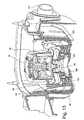
- FIG. 4 is a cutaway view of the flow generator
- FIG. 5 is an exploded view of components of the flow generator
- FIG. 6 is a vertical transverse cross-section of the flow generator
- FIG. 7 is a more detailed illustration of the bottom case and power supply of FIG. 5 ;
- FIG. 8 is a more detailed illustration of the chassis, chassis lid and fan housing of FIG. 5 ;
- FIG. 9 is a more detailed illustration of the PCB, top case and exterior fittings of FIG. 5 ;
- FIG. 9A is a schematic vertical cross-section detail of the connection of the handle to the flow generator top case
- FIG. 10 is an underneath view of a chassis forming part of the flow generator
- FIG. 11 is a vertical cross-section of the chassis through a venturi passage connecting muffler cavities of the flow generator;
- FIG. 12 is a general view of a fan forming part of the flow generator
- FIG. 13 is a vertical cross-section showing the fan mounting arrangement
- FIG. 14 is an exploded view of a humidifier adapted for use with the flow generator of FIG. 5 ;
- FIG. 15 is a rear view of the humidifier assembly
- FIG. 16 is a perspective of a seal for the air flow path
- FIG. 17 is an underside perspective of the humidifier lid of FIG. 14 ;
- FIGS. 18 and 19 are respectively a perspective and a detail cross section of the humidifier lid seal of FIG. 14 ;
- FIGS. 20 and 21 are respectively a perspective and a longitudinal cross section of the humidifier tub lid of FIG. 14 ;
- FIG. 22 is a graph of heater target temperature against humidifier setting
- FIG. 23 is a schematic circuit diagram of a power control circuit to the humidifier heater
- FIG. 24 illustrates reminder menus of the flow generator control
- FIGS. 25 to 34 show various modular data connector arrangements
- the illustrated apparatus comprises a flow generator 50 and a humidifier 150 , shown in their assembled condition in FIG. 1 , and separately in FIGS. 2 and 3 respectively.
- the flow generator engages with the separable humidifier at an engagement face 52 , from which protrudes an air connector 53 for the delivery of air from the fan to the humidifier container, electrical connectors 54 for the delivery of power to the humidifier heater and an optical coupling transmitter 200 and sensor 201 described further below.
- the face 52 also carries a pair of slots 55 which are engaged by corresponding tongues 156 provided on the humidifier engagement face 157 ( FIG. 15 ) by which the flow generator 50 and humidifier 150 are connected together, as will be described in more detail below.
- the flow generator 50 is also provided with an LCD screen 58 and associated keys 59 by which the user can set the operating parameters of the unit.
- the flow generator 50 has an external case of rigid plastics material moulded in two parts, a top case 60 and a bottom case 61 .
- the lower edge of the top case 60 is stepped and flanged at 62 ( FIG. 9 ) to mate with the periphery of the bottom case 61 .
- the bottom case 61 of flow generator 50 has a shell 120 of rigid plastics material, such polycarbonate/ABS blend, forming the structure of the case, integrally overmoulded with a lining 121 of an elastomer such as a synthetic rubber or thermoplastic elastomer which forms the seal 63 between the top and bottom cases and the chassis 64 and also forms the external feet of the case (see FIG. 6 ).
- a shell 120 of rigid plastics material such polycarbonate/ABS blend
- the lining 121 also covers the internal surface of the chassis-receiving cavity of the bottom case and the dividing wall 123 between the power supply cavity 65 and chassis-receiving cavity, the resulting composite of the rigid shell with elastomeric lining serving to reduce radiated noise levels from the flow generator by damping acoustic resonance of the walls.
- a power supply cavity 65 and a first muffler cavity 134 Formed in the bottom case 61 by walls which join the outer wall of the case are the lower parts and of, respectively, a power supply cavity 65 and a first muffler cavity 134 .
- the upper parts of these cavities are formed by the chassis 64 , described below.
- the first muffler cavity forms part of the air flow path from the air inlet 85 to the blower, receiving air from an air inlet path defined by the chassis 64 , as described below.
- the chassis 64 forms the blower or fan cavity 70 , inlet and outlet air flow paths and the top of the power supply cavity 65 .
- the fan cavity 70 includes a metal liner tub 73 insert moulded into the chassis as described below.
- the chassis 64 is formed with a peripheral wall 69 flanged around its lower edge to engage with the inner periphery of the overmoulded sealing flange 63 .
- the chassis 64 includes a downwardly extending fan cavity 70 in which is mounted the fan 90 described below.
- This cavity 70 is formed by moulded side walls 71 and base 72 , which are formed by moulding inner and outer layers of thermoplastic around an inserted steel liner tub 73 .
- the tub may be stainless steel, nickel plated mild steel or other suitable corrosion resistant metal.
- the fan cavity 70 opens to the upper surface of the chassis 64 to enable insertion of the fan 90 , this opening being closed by a lid 74 .
- the density and stiffness of the steel tub creates a highly effective barrier to transmission of the motor and fan noise, while formation of the cavity 70 by insert moulding from differing materials provides very effective acoustic damping, as does the combination by co-moulding of the hard and soft plastics described already and further described below.
- the use of co-moulding or overmoulding in the combination of materials of different, preferably widely different, stiffness and different, preferably widely different, density has been found to be particularly advantageous in providing acoustic damping.
- Preferred materials for the chassis and liner tub are polypropylene thermoplastic for the chassis and metal, preferably steel (optionally stainless steel), for the liner tub.
- the applicant has found that by forming the fan cavity as a composite of metal and polymer—having a differential in density of greater than 5 times, preferably about 7-8 times, and also significantly different stiffness and damping properties—the resonance peaks of the composite structure are well damped so that noise generated by the fan is well-suppressed by the fan cavity construction.
- the polymer for the chassis 64 be a glass fibre-filled polymer containing from 10-40%, and more preferably about 30%, glass fibre.
- the use of this material as a composite with a steel liner tub 73 gives both effective damping of fan noise and a good match in thermal expansion characteristics so that the composite material chassis performs well over a wide range of operating temperatures. Further, the Applicant has found that the use of glass fibres outperformed talc, bronze, glass bead filler materials for this purpose.
- the top of the fan cavity is formed by the chassis lid 74 , which is formed of an embedded steel insert overmoulded with elastomer to provide acoustic damping and sealing of the top of the fan cavity 70
- a preferred polymer lining for the lid is an elastomer, for example of the same type used for the lining 121 of the bottom case.
- the upper part of the power supply cavity 65 is formed by a side wall 75 extending downwardly from the roof of the chassis 64 , which sealingly engages the opposed wall of the lower portion of this cavity.
- the lower wall is provided for this purpose with a co-moulded or overmoulded rubber sealing flange 76 .
- the interior is at the same time acoustically sealed from the power supply cavity, which may not be completely sealed from the exterior, due to the necessity of providing mains power input and low voltage power output to the humidifier, via connectors 77 and 79 mounted in apertures 78 and 80 respectively in the rear and front walls of the cavity, and if necessary the venting of the compartment to outside air for cooling. This reduces assembly time and allows the overall device to be smaller.
- a power supply unit 124 is received in the power supply cavity 65 , for providing electrical power for operation of the fan, control functions and the humidifier heater pad.
- the power supply comprises a printed circuit board 133 , to which are directly attached by soldering or other suitable means a power inlet connector 77 , a fan power outlet connector 126 for the fan motor and a humidifier power outlet 79 .
- Each end of the power supply cavity 65 has mounting guides 136 for supporting the PCB of the power supply in an upright position so that installation of the power supply is achieved by drop-in assembly.
- the fan 90 and fan housing 93 , 94 fit into the fan cavity 70 of the chassis and connect to electrical connector 26 at the top of the power supply PCB. Elastomer overmoulding of the base 94 of the fan housing seals the housing, provides acoustic damping of the fan housing base and forms feet on the bottom of base to act as bump stops protecting the fan in case the unit is bumped or dropped.
- a printed circuit board 81 carrying the electronic control components of the unit.
- the printed circuit board 81 preferably includes an LCD display 58 .
- an edge connector 1082 and a sliding connector 1082 A may be accessible from a connector aperture in the rear of the case 60 , providing for modular connector arrangements to be described in more detail below with reference to FIGS. 25 to 34 .
- an air inlet 84 is also provided in the rear wall of the top case, and this communicates with an air inlet passage 85 formed in the chassis above the roof of the upper portion of the power supply cavity 65 , this passage in turn opening to first muffler cavity 134 surrounding the bottom of the fan cavity of the chassis.
- the top case further defines, an air inlet to the flow generator, and has a replaceable filter 129 of any suitable material, such as foam or fibre, and filter cover 130 fitted to the top case 60 .
- An inlet wedge 131 serves as an airflow guide.
- a blank cover 132 clips in place over apertures in the case which align with connectors 1082 , 1082 A to provide ports on the PCB for communications, etc. Further details of the communications and/other electrical ports in the flow generator case will be described later with reference to FIGS. 25 to 34 .
- connection passage 137 ( FIG. 11 ) into a second muffler volume formed by the space between the fan cavity 70 and the fan.
- the fan cavity and the space between the bottom case and the chassis thus form a pair of serially connected volume mufflers, with a restricted diameter passage therebetween.
- Noise attenuation produced by a muffler system is generally proportional to the ratio of a representative diameter of the muffler volume to that of the constriction, and thus an optimal muffler design must balance optimal noise attenuation against the constraints of available muffler volume—especially in a compact machine—and avoiding unacceptable air flow restriction through the constriction.
- the Applicant has found that a favourable adjustment of this balance may be achieved by forming the intermediate connecting passage 137 between the muffler volumes as a venturi, as shown in FIGS. 10 and 11 , with a relatively short, smoothly varying diameter lead in portion 137 a at the end adjacent the first muffler, an intermediate constriction 137 b and a gradually expanding lead out portion 137 c at the downstream end.
- the muffler system can achieve the noise attenuation according to the representative diameter of the smallest diameter portion, with better pressure drop characteristics.
- FIGS. 12 and 13 It will now be convenient to describe the features of the fan, which are shown in FIGS. 12 and 13 .
- the fan 90 comprises a motor 91 , preferably brushless DC motor, provided with a coaxial impeller 92 , mounted vertically within a fan housing consisting of a cover 93 and a base 94 .
- An air inlet 95 is provided in the floor of the base 94 on the impeller axis, and cavities in the cover and base form a volute 96 which leads from the impeller to an air outlet 97 .
- the cover and base 93 and 94 are joined by means of slotted tabs 98 which extend upwardly from the base to snap over stepped ribs 99 , the tabs 98 being further located by fitting between parallel ribs on the cover 93 .
- the joint between the cover 93 and the base 94 is sealed by an elastomeric over- or co-moulded sealing ring 101 .
- the bottom surface of the fan housing base 94 is provided with radial stiffening ribs, and overmoulded to the base 94 is an elastomer damping member 103 which covers that bottom surface between the ribs, and extends around the edge of the base by a flange portion and peripherally spaced tabs.
- an elastomer damping member 103 which covers that bottom surface between the ribs, and extends around the edge of the base by a flange portion and peripherally spaced tabs.
- feet 106 Moulded integrally with the rigid plastics portion of the fan housing base are feet 106 which extend proud of overmoulded elastomer member 103 to receive helical mounting springs 102 ( FIG. 13 ), preferably of metal, by which the fan is mounted on the base 72 of the fan cavity.
- the degree of size reduction which is an objective of the present invention requires great care to be taken to minimise the transmission of noise and vibration, particularly from the motor and the impeller of the fan 90 .
- the mounting springs are therefore chosen to ensure minimal transmission of the vibration frequencies encountered during operation. This is achieved by choosing the springs with reference to the mass of the fan 90 , such that the natural frequency of the system comprising the springs and the fan is less than approximately one tenth of the shaft speed of the motor when running at its lowest operating speed.
- the air outlet 97 upon the introduction of the fan into the fan cavity, is connected by means of a thermoplastic elastomer or silicone rubber coupling member 108 with an air passage which extends from the side wall of the fan cavity to a connecting nozzle 110 extending through an aperture provided for this purpose in the front face of the flow generator.
- the coupling member 108 includes at least two corrugations which provide flexibility to the connection and improved resistance against transfer of vibration from the fan to the flow generator case.
- the fan 90 therefore floats within its cavity 70 in the chassis 64 with minimum acoustic coupling to the remainder of the flow generator.
- the characteristics of the mounting springs and the coupling member 108 are chosen to minimise the transmission of characteristic vibration frequencies of the fan.
- the illustrated flow generator construction and materials combinations are adapted to result in a compact CPAP flow generator unit of similar performance and noise characteristics to larger units—eg. capable of generating from 4-20 cm H 2 O pressure and a flow rate of 120 L/min and a total radiated noise volume of less than 33 dbA, more preferably less than about 30 dbA, when operating at 10 cm H 2 O—in a flow generator unit having a total volume of about 2 litres or less.
- the handle 128 has opposed arms with inwardly projecting pins 140 at their distal ends.
- the top case 60 includes a pair of channel-shaped tracks 141 with one open and one closed end, for receiving respective of the pins.
- the facia 127 clips onto the top case 60 , and includes projections 142 which trap the pins 140 in the end of their tracks 141 .
- the handle attachment configuration thus provides a quick and simple means of assembly without requiring flexing of the handle arms to locate the pins into small recesses as in the prior art.
- the humidifier 150 comprises a base unit designed for simple attachment to and detachment from the flow generator 50 , which forms a cradle for a water container which is in turn attachable to and detachable from the base unit.
- the general arrangement of the humidifier components includes a base (rear cover 803 and front cover 602 ) onto which is fitted a heater comprising a heater plate (plate 632 with ceramic heater pad 800 ) which supports a water tub (tub base 698 , seal 699 and tub lid 700 ) and a hinged humidifier lid 648 which seals against the tub lid 700 to form an air path into the tub through the tub lid.
- a heater comprising a heater plate (plate 632 with ceramic heater pad 800 ) which supports a water tub (tub base 698 , seal 699 and tub lid 700 ) and a hinged humidifier lid 648 which seals against the tub lid 700 to form an air path into the tub through the tub lid.
- the rear face of the base has a peripheral flange 153 which seats in a corresponding peripheral recess 113 surrounding the front face of the flow generator 50 when the two units are brought together by linear movement towards each other.
- a latch 404 is held in place by latch retainer 404 a to be moveable vertically and resiliently urged downwardly by spring 404 b , so that the tongues 156 engage in the slots 55 and snap home to engage the two units by means of the downwardly extending fingers 158 at the ends of the tongues.
- the PCB of the flow generator is provided at the end adjacent the humidifier with an optical transmitter 200 which emits a periodic flash of light from the end face of the flow generator case, and an optical sensor 201 to detect the presence or absence of the humidifier.
- the rear face of the humidifier contains a curved reflector 202 which, when the humidifier is attached to the flow generator, completes an optical path from the transmitter to the sensor so that the flow generator PCB detects the presence of the humidifier and may adjust the control algorithms accordingly.
- the rear face of the base unit also carries a connector 162 , in this embodiment a pair of flat male blade connectors, for engagement with a mating connector 114 on the front face of the flow generator, to provide power to the humidifier heater from the power supply in the power supply cavity 65 .
- the respective faces may also carry further interconnecting devices, where other electrical or data connections are required to be established between the flow generator and the humidifier or downstream devices including the air conduit or the mask. Such devices may take the form of optically coupled devices, or connectors of other suitable kinds.
- an opto-coupling connector enables the implementation of a simple protocol for communications between the flow generator and the humidifier. For example, the current flow levels of the flow generator can be sent to the humidifier controller which then adjusts the operation of the humidifier according to a predetermined algorithm.
- the back cover 803 which fits to the rear of the front cover 602 provides the air, electrical and communications connections to the flow generator and provide support for a control PCB 804 and the catch assembly.
- the catch assembly includes a latch 404 which is retained by a latch retainer 404 a and spring 404 b , and operates to attach the humidifier to the flow generator generally as described for the earlier embodiments.
- a control knob 805 on the top of the front cover 602 is connected to the PCB 804 to allow patient control over the degree of humidification.
- an aperture 264 ( FIG. 15 ) for electrical connections between the humidifier and the flow generator, or for electrical and signal connections to the humidifier.
- the air port 807 in the humidifier rear face mates with the outlet 110 of the flow generator.
- An elastomer airway seal 722 fits between the front and back covers to connect the air port 807 in the back cover 803 to the aperture 626 of the front cover 602 .
- the seal (shown in more detail in FIG. 16 ) has an inlet connector portion 722 a which connects to the flow generator output via the air port 807 formed in the back cover 803 , and a peripheral seal portion 722 b which extends about the aperture 626 periphery at the front face of the cover 602 .
- a wall portion 722 c of the seal closes off a lower part of the aperture 626 , leaving a smaller aperture 722 d defined by the seal.
- the airway seal 722 defines a closed passage from the circular air port 807 to the rectangular aperture 722 d in the vertical wall of the front cover.
- the heater pad comprises lower and upper parts 806 , 800 and a heater pad cover 632 .
- the heater pad cover 632 has an upper heating surface 634 , a downwardly extending peripheral wall 636 acting as a further heating surface and a rear flange with a pair of attachment portions 640 for attachment of the heater pad to tubular protrusions 628 on the rear of the front cover 602 .
- the heater pad cover 632 is configured to accommodate, below the upper wall 634 and within bounds of the wall 636 , a heater pad or other heating means such as an induction heater, for causing heating of the water in the humidifier water container.
- the front of the heater pad cover 632 has a forwardly extending tab 646 of dog-legged shape, which extends to the front of the humidifier cradle front cover 632 to support the heater and also provide a catch for the humidifier lid 648 .
- the water container consists of a water tub 698 , seal 699 and tub lid 700 .
- the floor of the tub 698 is of complementary shape to the heater pad, and is formed of metal or other material suitable to conduct heat from the heater pad to the water in the tub.
- the floor has a generally horizontal portion 900 corresponding to the upper heating surface 634 of the heater pad and a U-shaped portion below the level of the heater pad upper surface, including a generally vertical heat transfer portion 902 below the horizontal portion corresponding to the peripheral heating surface.
- the rear surface of the tub lid has an air inlet aperture 801 leading to an inlet end of the U-shaped air passage 718 .
- the tub 698 and tub lid 700 are pressed rearwards so that the peripheral seal 722 b abuts the rear surface of the tub lid in a locus surrounding the rear opening of the inlet aperture 801 , creating a sealed air path from the flow generator outlet to air passage 718 and into the headspace of the humidifier tub. This allows the humidifier tub to be removed for refilling and replaced without the need for a separate operation to connect the air flow.
- the inside wall of the tub lid 700 has projections 802 a , 802 b which serve to limit the press fitting of the tub lid onto the tub base 698 .
- One projection 802 a is provided at the front of the tub, and further projections 802 b , or sets of projections, are provided on opposed side walls of the tub lid, forward of the rear of the tub.
- This positioning of the projections 802 b allows one-handed disengagement of the tub base and tub lid by squeezing together of the base and lid at their rear end, causing the connection to pivot about the side projections 802 b and the tub and lid to separate at the front.
- the ability to separate these components one-handed is a feature of considerable utility, especially for stroke patients or other users with limited dexterity.
- the water container lid 700 has an air passage 718 formed as a U-shaped channel, leading to the humidified air entry aperture 720 into the headspace of the water container.
- the channel floor slopes down in the direction of air flow from the air inlet end to the end at which the air enters the water container.
- the water container lid also has an elliptical humidified air exit aperture 722 .
- Water may be added to the water container via the air exit aperture 722 while the tub lid is in place, or by removing the tub lid.
- the tank is intended to be filled via the air outlet 722 , and the apparatus may be provided with a filling bottle with a spout dimensioned for a convenient fit with that outlet.
- a filling bottle with a spout dimensioned for a convenient fit with that outlet.
- Such a bottle may be provided with a spout of the kind incorporating an air bleed passage which will allow the tank to fill to the correct predetermined height.
- filling arrangements may be employed, for example by removing the tub lid.
- the correct filling height may also indicated by filling level graduations scribed or otherwise marked on the wall of the water tub.
- a microswitch (not shown) or other sensing means may be provided to turn off power to the heater pad when the lid is opened, and/or when the water container is removed.
- FIGS. 17 to 19 show the underside of the humidifier lid 648 and the seal 676 which provides a seal to the tub lid 700 about the U-shaped passage 718 and the humidified air exit aperture 716 .
- the seal 676 comprises an edge seal portion 676 a and membrane portion 676 b , as shown in FIGS. 18 and 19 .
- the lid 648 has an upper wall 650 and a front wall 652 which extends downwards, and outwardly, from the upper wall.
- the upper wall 650 has a recess at its rear side, such that the part of the upper wall and front wall 652 on each side of the recess constitutes a rearwardly projecting arm 656 .
- the hubs 658 are configured to be received in the sockets 622 of the humidifier front cover 602 such that each hub and its corresponding socket constitute a hinge connection, for attaching the lid 648 to the front cover.
- the lid 648 During opening of the lid 648 , it may be freely rotated about the hubs through greater than 90° until it reaches a maximum extent of normal travel.
- the lid and front cover are configured such that, if the lid is then rotated further, the hubs pop out of the sockets 622 . This may be achieved, as would be understood by a person skilled in the art, by providing suitable chamfers on the hubs and/or sockets, or other suitable formations on the lid or cover, so that the lid flexes to release the hubs from the sockets.
- each arm 656 is shaped complementarily to the shape of the upper portion of the face of the front cover to accommodate that part of the arm when the lid 648 is in a closed position.
- the lid 648 includes a humidified air outlet pipe 662 which passes through the upper wall 650 and extends upwards and forwards at an acute angle from the top of the upper wall, for attachment of a hose to supply humidified air to a patient.
- the pipe 662 continues below the lower surface of the upper wall 650 to define an elliptical rim 664 .
- a wall 666 Extending downwards from the lower surface of the upper wall 650 is a wall 666 which is configured to define a closed path and hence a U-shaped enclosed region 668 within the confines of the wall.
- a recessed notch 674 on the rear (inner) surface of that wall, for snap-fit engagement with the tab 646 of the heater pad cover to act as the catch for the lid.
- the lid may be opened by flexing the assembly to release the tab from the notch.
- the edge seal portion 676 a of the lid seal includes a channel 676 c which fits over the wall 664 and rim 666 on the bottom of the lid 648 , and a curved sealing flange 676 d which seals against the top surface of the tub lid, so that the space between the U-channel 718 on the tub lid and the seal membrane forms an inlet air passage of the tub, and the air outlet aperture 722 of the tub lid communicates via the elliptical opening 676 e in the lid seal to the air outlet pipe 662 of the humidifier lid 648 . This is achieved without the need to connect and disconnect air tubes to remove the water container.
- the air from the flow generator passes into the water container, the air then travels across the surface of the water so that the air becomes humidified.
- the heating of the water by the heating pad enhances this humidification.
- the air then exits the water container through the outlet opening 716 to the air outlet pipe 662 , which is in turn attached to a suitable hose (not shown) for supplying the humidified air to a patient.
- the air mass within the container is caused to swirl and thus enhance the uptake of water vapour from the water contained in the tub.
- the enhanced uptake of water vapour achieved by inducing the swirling of air as it passes through the tank enables, in an alternative embodiment of the invention, the elimination of the heating of the water in the tub.
- the heating element and its controls, and the heat transfer components including the heating plate and the metal tank base are eliminated, and the humidifier becomes a simpler, passive, device.
- a humidifier assembly in accordance with the present invention has a number of advantages over the prior art.
- One advantage relates to convenience of use. Convenience of use is important for all patients, especially those who have poor dexterity.
- the base of the humidifier assembly includes a generally “negative” U-shaped channel.
- the bottom portion of the water tub has a corresponding “positive” U-shape.
- the outer wall of the U-shape is sloping, whereas the inner wall is generally vertical. Because the base and water tubs have complementary configurations, placing the water tub generally in the correct position means that it will to some extent self-align into the correct position, which as described below, is a sealing position.
- a water tub according to the present design can be easily placed in a sealing position without requiring a patient to connect small fiddly tubes such as used in the prior art.
- An aspect of this is that a seal is provided by placing a generally flat surface such as the rear of the water tub, or the top surface of the water tub, against respective silicone gaskets that present a corresponding flat surface. The respective seals are formed when the two flat surfaces contact.
- the humidifier assembly has a very convenient “drop-in” configuration.
- the water tub is held in position by the simple motion of swinging the pivoting lid through approximately 90° from fully open to closed.
- the lid is locked in position via a robust mechanism which provides and audible and reassuring “click”-sound when engaged. Whilst in the preferred embodiment, a pivoting movement is used for the lid, other movements are contemplated including sliding and translation.
- the lid of the humidifier assembly includes an air delivery tube connector, which in a preferred form is generally cylindrical. Connection of the air delivery tube to the lid can be achieved regardless of whether the water tub is in position. This arrangement means that the water tub can be removed and refilled with water if necessary without requiring disengagement of the air delivery tube from the humidifier assembly.
- the illustrated humidifier construction provides a compact humidifier adapted for ease of manufacture and use, and further provides protection against backflow of water into the flow generator when the humidifier and flow generator units are assembled together.
- Backflow protection is provided by the sloping floor of the air passage and the location of the air inlet aperture 801 and the aperture 722 d in the seal 722 relative to the air inlet 720 from the air passage 718 into the headspace of the humidifier tub 698 .
- the tub is overfilled while in its horizontal position, the water will flow back along the U-shaped air passage 718 only as far as its forwardmost portion, which has a front wall 717 lower than the air inlet aperture 801 , and will drain towards the front of the machine.
- the water will be prevented from flowing back along the air passage from the tub to the air inlet 801 as the intermediate portion of the air passage 718 will be above the level of the aperture 720 . The water will then flow back into the tub once the machine is righted.
- either the air inlet aperture 720 or the air inlet 801 will be above the water level and thus water should not flow back into the low generator. Again, any water which escapes the tub will flow back into the tub once the machine is righted.
- a non-return valve at an appropriate point, for example a flexible membrane supported in the mouth of the humidifier air inlet.
- the contour of the lid seal is adapted to collect condensation which may form in the lid cavity and the headspace of the water receptacle, preventing backflow of this condensation to the flow generator when the lid is opened.
- the configuration of the front and back covers of the humidifier and of the heater pad is adapted to allow fitting together in a vertical orientation, to minimise the need for reorientation during assembly of the humidifier unit on the production line.
- the resilience of the connection between the lid and the water receptacle, provided by the lid seal is adapted to maintain downwards pressure on the water receptacle when the lid is closed, to maintain good heat-transfer contact between the base of the water receptacle and the heater pad without the added complexity and expense of spring-loaded mounting of the heater pad.
- the humidifier is provided with a control knob allowing adjustment of the humidity of the air supply to the patient.
- the control knob may have a smoothly variable control, or a series of discrete humidity settings, and will have an ‘off’ setting where no power is supplied to the heating pad.
- the correlation between the humidity setting and the power to the heater is controlled by a circuit on the PCB 804 .
- FIG. 22 is a sketch of a preferred calibration curve of target water container temperature (y axis) against humidity setting (x axis), including upper and lower tolerances.
- the heater control selects a very low target heater temperature—less than ambient temperature, and preferably lower than the lowest operating temperature of the humidifier. In this way, the heating is turned off when the control knob is in its off position, while allowing use of a less expensive potentiometer without an integral off switch or a separate on/off switch.
- the mounting of the control knob mechanism may provide a tactile ‘click’ at the off position of the control knob, to confirm to the user that the heater is turned off.
- FIG. 23 is a circuit diagram of the humidifier control circuit for controlling the water temperature, including a potentiometer POT 1 actuated by the control knob 805 and an operational amplifier OA 1 providing power to the heater 800 .
- a potentiometer may be used in series with the heating element to set the operating temperature. However, this may result in large heat losses through the potentiometer as in the following equation
- RH the resistance of the heater and is fixed
- RP the resistance of the potentiometer which is variable and provides the temperature control.
- the potentiometer is used in the control path of a semiconductor arrangement to set the operating temperature. This substantially reduces the current through the potentiometer because the potentiometer now only carries a semiconductor control current rather than the load current required to drive the heater element.
- the potentiometer is used in conjunction with a temperature sensing element to control an operational amplifier which drives the heater directly or through a high current semiconductor switch.
- FIG. 23 shows an arrangement for controlling temperature via an operational amplifier OA 1 .
- the operational amplifier n 1 has a pair of inputs, V+ being an adding input and V ⁇ being a subtracting input.
- the output of the amplifier is proportional to the difference between the voltages on the inputs V+ and V ⁇ .
- Input V ⁇ is connected to a reference voltage determined by the ratio of resistors R 21 and R 17 ;
- V ref Vs*R 12/( R 12+ R 17)
- the temperature of the water is sensed by temperature sensitive resistive element, thermistor TH 1 , and the operating point is set by potentiometer POT 1 .
- the operational amplifier input V+ is connected to the junction of R 106 and thermistor TH 1 .
- the operational amplifier switching threshold is determined by the ratio of the resistance of the potentiometer POT 1 plus resistor R 106 to the resistance of the resistance network formed by thermistor TH 1 plus resistor R 11 in parallel with resistor R 10 plus resistor R 10 equals the ratio of resistor R 17 to resistor R 21 . That is, the operational amplifier switches when the junction between the thermistor TH 1 and resistor R 106 crosses over the potential at V ⁇ .
- the operational amplifier is powered from supply points Vss and Vo, so the drive current does not pass through the potentiometer.
- Vss may be the same as Vs
- Vo may be the same as 0 v.
- the operational amplifier may drive the heater element directly or it may control a power transistor which drives the heater element.
- This arrangement significantly reduces the dissipation through the potentiometer, allowing a smaller potentiometer, with smaller cooling needs, to be used.
- the arrangement is also well adapted for use in implementing the ‘soft’ off setting arrangement described above with reference to FIG. 22 .
- FIG. 24 is a flowchart of a Reminder menu to set a number of reminders to alert the patient to specific events; for example, when to replace their mask, when to insert a Data Card (if their device is Data Card enabled) and so on. It can also be used to set special customised reminders.
- a reminder When a reminder is due, a message is displayed on the LCD and remains whenever the device is not delivering therapy.
- the backlight on the LCD flashes when a message is displayed. If more than one reminder for a patient is scheduled for the same date, all scheduled reminders are displayed during that day.
- a patient can clear a message by pressing the LEFT key (or inserting a Data Card, in the case of the Data Card reminder).
- the default setting for all reminders is that they are disabled.
- the patient enters the Reminder Menu from the standby screen by pressing LEFT and DOWN for at least three seconds.
- FIG. 24 summarises the Reminder Menu screens:
- REPLACE MASK to set a timed reminder to remind a patient when they need to replace their mask.
- the patient can press the LEFT (clear) key to remove the message from the LCD.
- CALL PROVIDER to set a reminder for the patient to phone the therapist at a certain time; for example, to discuss how their therapy is going.
- the patient can press the LEFT (clear) key to remove the message from the LCD.
- INSERT CARD if a patient's flow generator is Data Card enabled, the therapist can set a timed reminder on the flow generator to remind them that they need to insert a Data Card to transfer patient data. This enables the therapist to establish compliance. The patient should actually insert the Data Card in order to clear the message from the LCD. (They can also press the LEFT (clear) key to remove the message.)
- REPLACE FILTER to set a timed reminder to remind the patient when to replace the air filter.
- the patient can press the LEFT (clear) key to remove the message from the LCD.
- FIGS. 25 to 32 are rear views of the flow generator, showing various forms of modular data connections foreshadowed earlier, utilising the slot 83 in the rear of the flow generator housing.
- the slot 83 is provided in the wall of a rectangular recess 1115 .
- An arcuate depression 1123 is provided in the upper surface of the unit above the recess 1115 to facilitate removal of closure elements from the depression, as described below.
- an edge connector 1082 and a sliding connector 1082 A are aligned with and accessible through the connector slot 83 in the rear of the case 60 , providing for the modular connector arrangements to be described in more detail below.
- the slot 83 is closed off by a blank closure element 132 , shaped to fit into the recess 1115 .
- the closure element is shown in more detail in FIG. 27 . This element snaps into the recess by means of lower tabs 1118 and an upper tab 1119 which fit corresponding depressions such as 1122 in the walls of the recess 1115 , to close the slot 83 and conform to the contours of the surrounding surface of the unit.
- Complementarily shaped closure elements can be provided for the reception of different kinds of data devices. Shown in FIG. 28 is an element 1116 a provided with a slot for the reception of a smart card 1120 .
- the element 1116 a or the printed circuit board itself may carry the necessary smart card socket.
- FIG. 29 Shown in FIG. 29 is a closure element 1116 b provided with a DB type data socket.
- the element 1116 b is contoured to provide a lower front recess 1121 to facilitate gripping of the associated plug.
- FIG. 29A A cross-section of a modified form of this arrangement is shown in FIG. 29A , illustrating the connection between the internal connector 1086 of the element 1116 b and the edge connector 1082 of the PCB, and the external DB9 connector 1088 .
- element 1116 can be provided to enable the connection of devices such as memory cards and pre-programmed devices as required.
- This facility furthermore enables a wide range of devices to be integrated with the apparatus in modular fashion, for example a clock display which may utilise the system clock contained in the flow generator controller, a voice activation unit, oximetry, ECG and other diagnostic aids, a sound recorder, a light.
- FIGS. 30 to 32 are a series, of rear perspective views of the flow generator, illustrating one embodiment of the modular data connector arrangement.
- FIG. 33 shows the front, inner surface of the USB closure element module
- FIG. 34 is a vertical cross-section of the flow generator.
- FIG. 30 shows the slot 83 open, exposing the edge connector 1082 and sliding connector (not visible in this view) at the rear of the flow generator PCB 81 .
- the connectors 1082 , 1082 A comprise a plurality of electrical contacts for carrying data and/or power between the PCB and an external device.
- FIG. 31 shows the arrangement of FIG. 31 where no data connection is required, with the slot covered by a blank closure element 132 generally as described above with reference to FIGS. 25 to 27 .
- FIG. 32 shows a removable closure element module 1116 c carrying a standard universal serial bus (USB) port 1084 on its rear surface.
- the element 1116 c incorporates an electrical/data pathway to an electrical connector 1090 at its forward, inner surface ( FIGS. 33 and 34 ) adapted to connect with all or selected ones of the contacts of the PCB connector 1082 for electrical and/or data transmission.
- the closure module 1116 c has internal electrical components completing a data and/or electrical pathway between its internal and external connectors so that the module acts as an adaptor between the PCB connector and a standard USB port.
- the cost and size of the flow generator unit may be reduced as the unit may be provided with only those connectors which are needed by that patient, and additional connector modules supplied only if the need arises. Furthermore, the arrangement facilitates upgrade of the data connection arrangement of the flow generator to keep up with technological advances or changes in global data connection standards.
- the word “comprising” is to be understood in its “open” sense, that is, in the sense of “including”, and thus not limited to its “closed” sense, that is the sense of “consisting only of”.
- a corresponding meaning is to be attributed to the corresponding words “comprise, comprised and comprises where they appear.
Landscapes
- Health & Medical Sciences (AREA)
- Emergency Medicine (AREA)
- Pulmonology (AREA)
- Engineering & Computer Science (AREA)
- Anesthesiology (AREA)
- Biomedical Technology (AREA)
- Heart & Thoracic Surgery (AREA)
- Hematology (AREA)
- Life Sciences & Earth Sciences (AREA)
- Animal Behavior & Ethology (AREA)
- General Health & Medical Sciences (AREA)
- Public Health (AREA)
- Veterinary Medicine (AREA)
- Air Humidification (AREA)
Abstract
Description
- 1. Field of the Invention
- This invention relates to breathable gas supply apparatus, and particularly but not exclusively to such apparatus for use in Continuous Positive Airway Pressure (CPAP) treatment of conditions such as Obstructive Sleep Apnea (OSA) and other respiratory disorders and diseases such as emphysema. It will be described herein in its application to CPAP treatment apparatus, but it is to be understood that the features of the invention will have application to other fields of application, such as mechanical ventilation and assisted respiration.
- 2. Description of Related Art
- CPAP treatment of OSA, a form of Noninvasive Positive Pressure Ventilation (NIPPV), involves the delivery of a pressurised breathable gas, usually air, to a patient's airways using a conduit and mask. Gas pressures employed for CPAP typically range from 4 cm H2O to 28 cm H2O, at flow rates of up to 180 L/min (measured at the mask), depending on patient requirements. The pressurised gas acts as a pneumatic splint for the patient's airway, preventing airway collapse, especially during the inspiratory phase of respiration.
- CPAP machines comprising an air flow generator for supplying pressurised air to the patient are known, and over recent years there has been commercial imperative for more compact CPAP machines. However, in seeking to reduce the size of the CPAP machines there has been a trade-off between reduced size on the one hand and reduced performance and/or increased noise on the other, for example Malinckrodt/Tyco/Puritan Bennett ‘Goodnight’ Series.
- The advantages of incorporating humidification of the air supply to a patient are known, and CPAP machines are known which incorporate humidifying devices, either separately from the flow generator or integrated therewith. An example of an integrated flow generator/humidifier unit is the ResMed® S7 sold by the present Applicant.
- Another problem with some flow generators is extensive use of foam in the air path for sound absorption. The foam can degrade with time.
- One of the objects of the invention is to provide a simple and compact breathable gas supply apparatus incorporating a humidifier which is simple and economic in its construction, compact, and easy to use. Other objects and advantages of the invention will be described throughout the specification.
- It is to be understood that apparatus described herein contains a number of advances on the prior art, many of which are independent inventions, although they contribute together to the realisation of the general object expressed above.
- The apparatus described herein incorporates novel aspects of architecture of both the flow generator and the humidifier, and of their integration, which contribute to a reduction in size compared with known units having similar performance. Techniques for noise reduction and damping are described which enable such a smaller machine to have noise performance which is at least as good as known larger machines.
- The apparatus described herein achieves full integration of the humidifier with the flow generator, in the sense that air flow, electrical and, if required, data connection between the flow generator and the humidifier are provided automatically upon the physical engagement of the two devices, without the need for any other process of interconnection.
- In such an integrated device, provisions to guard against flowback of water from the humidifier tank to the flow generator are important, and novel sealing arrangements, and novel arrangements for minimising the occurrence of flowback while at the same time improving the uptake of water vapour in the humidifier are also described. The humidifier is readily detached and replaced on the machine, and has very few parts to be disassembled during cleaning.
- Also described herein are improved, modular, devices for enabling data connection with the apparatus, including the connection of data storage devices such as memory cards, smart cards, communication ports and the like to be selectively attached by the user or by medical personnel.
- Another aspect of the invention is to reduce or eliminate the use of foam in the air path.
- In one form, the invention provides a flow generator unit for delivering breathable gas to a patient, including:
-
- a flow generator case;
- a powered gas flow generator within the case;
- a power supply unit adapted for drop-in assembly in said case, said power supply unit including a printed circuit board, a power input connector rigidly attached to said printed circuit board and a power output connector, and a power supply unit mounting for mounting said power supply unit in said case such that said power input connector aligns with a power input port of said case.
- A further form of the invention provides a blower enclosure for a flow generator used in delivery of breathable gas to a patient, said blower enclosure including a metal container overmoulded with an acoustically damping polymer lining.
- A further form of the invention provides a blower enclosure for a flow generator used in delivery of breathable gas to a patient, said blower being adapted to reduce noise from the enclosed blower, said enclosure comprising:
-
- a cavity within a chassis of the flow generator, the cavity defined by side walls and base, the enclosure being adapted to receive and mount a blower in said cavity and
- a lid adapted to be mounted on said chassis so as to form a top surface of the cavity,
wherein at least one of the chassis and lid is moulded from a composite comprising a metal and a plastic.
- A further form of the invention provides a blower for a flow generator used in delivery of breathable gas to a patient, said blower comprising an electric motor with a shaft, an impeller adapted to be mounted on the shaft, and a volute having an air-inlet and an air-outlet, the volute defining a chamber in which a flow of air at pressure is developed, the volute being moulded from a composite comprising a first plastic material and a second plastic material, the first plastic material being generally rigid and the second material being generally elastomeric.
- Preferably, wherein the first plastic material is overmoulded with the second plastic material.
- Preferably, the volute comprises an upper volute and a lower volute, the lower volute incorporating the air-inlet. Preferably also, the lower volute includes feet moulded from the second plastics material.
- Preferably, the upper volute incorporates the air-outlet. Preferably also, the upper volute includes a seal constructed from the second plastic material and which in use is adapted to provide a seal between the upper and lower volutes.
- In one embodiment the upper and lower volutes are adapted to be snap-fitted together.
- A further form of the invention provides a flow generator case for a flow generator used in delivery of breathable gas to a patient, said flow generator case comprising a shell of rigid plastics overmoulded with an elastomeric lining.
- Preferably, said elastomeric lining forms external feet of said flow generator case.
- A further form of the invention provides a fan support arrangement for a flow generator used in delivery of breathable gas to a patient, including a fan housing containing a motor and fan, said support arrangement including a plurality of mounting springs, wherein said springs, fan housing, motor and fan form a spring system having a natural resonant frequency less than one tenth of the frequency of a lowest operating speed of said fan.
- A further form of the invention provides a flow generator unit for delivering breathable gas to a patient, including a flow generator case having an air outlet, a fan volute contained within said case, further including a flexible tube connecting an outlet of said fan volute to said air outlet, said flexible tube having two or more corrugations therein.
- A further form of the invention provides a flow generator and humidifier combination for continuous positive airway pressure treatment of a patient, including a flow generator and a humidifier removably attached to the flow generator, wherein said flow generator includes a humidifier attachment detector including an optical transmitter and an optical sensor and wherein said humidifier includes an optical path connector which, when said flow generator and humidifier are attached, completes an optical path between said optical transmitter and said optical sensor.
- A further form of the invention provides a muffler arrangement in an air flow path of a flow generator used in delivery of breathable gas to a patient, including a first muffler volume, a second muffler volume and a connecting portion linking said first and second muffler portions, wherein said connecting portion is narrow relative to said muffler portions and includes a lead-in portion which narrows in a direction away from said first muffler portion.
- Preferably said connecting portion includes a venturi.
- A further form of the invention provides a handle assembly for a flow generator used in delivery of breathable gas to a patient, including a flow generator case, a handle including a pair of attachment arms, each attachment arm having a projection received in a respective track of said case, and a handle retention member which attaches to said case to retain said handle projections against travel along said track.
- A further form of the invention provides a method of attachment of a handle to a flow generator case, said handle including a pair of attachment arms, each attachment arm having a projection received in a respective track of said case, including the steps of sliding said handle projections along respective of said tracks and attaching a handle retention member to said case to retain said projections against travel along said respective tracks.
- Preferably, said sliding of said handle projections along said track occurs without substantial distortion of said attachment arms.
- A further form of the invention provides a humidifier for delivering humidified breathable gas to a patient, including a humidifier case,
-
- a water container,
- a heater located in heat transfer communication with said water container, a gas flow path including a gas inlet, a humidified gas outlet and an intermediate gas flow path which contacts the gas with water vapour from said container,
further including a drainage opening adjacent said heater allowing drainage of water past the heater to exit said humidifier case.
- A further form of the invention provides a humidifier for delivering humidified breathable gas to a patient, including
-
- a humidifier case,
- a water container,
- a heater pad located in heat transfer communication with said water container, a gas flow path including a gas inlet, a humidified gas outlet and an intermediate gas flow path which contacts the gas with water vapour from said container,
wherein said heater pad has an upper heating surface and a peripheral heating surface which includes a side wall of said heater pad, and wherein a heat transfer surface of said water container is shaped to correspond to said heater pad so as maintain close heat transfer communication with said upper heating surface and peripheral heating surface of said heater pad.
- Preferably, said water container defines a water volume which extends both above and below a level of said heating pad upper heating surface.
- A further form of the invention provides a humidifier for delivering humidified breathable gas to a patient, including
-
- a humidifier case having a hinged lid,
- a water container adapted for drop-in assembly in said case,
- a heater in heat transfer communication with said water container,
- a gas flow path including a gas inlet, a humidified gas outlet and an intermediate gas flow path which contacts the gas with water vapour from said container,
wherein said water container has a gas passage inlet communicating with said gas flow path,
said humidifier further including a gas passage inlet seal for sealing connection said gas passage inlet to said gas flow path, wherein said sealing connection is actuated by drop-in assembly of said water container and hinged closing of said lid.
- Preferably, said gas passage inlet is located on a rear face of said water container and aligns with a gas passage aperture on an opposed face of said case.
- A further form of the invention provides, in a humidifier assembly for a flow generator used in delivery of a supply of breathable gas to a patient for treatment of sleep disordered breathing, the humidifier assembly comprising a water tub having an inlet, a base having a blower outlet and a water-tub-receiving-portion, and a hinged lid with an engagable locking mechanism, a method of forming a seal between the water tub inlet and the blower outlet of the base comprising the steps of:
-
- placing the water tub in the tub-receiving-portion of the base so as to position the inlet and the outlet adjacent one another;
- closing the hinged lid; and
- engaging the locking mechanism.
- Preferably, the blower outlet includes front-facing seal forming surface, and the step of placing the water tub in the water-tub-receiving portion of the base further includes the step of placing the water tub against the seal forming surface of the blower outlet.
- A further form of the invention provides, in a humidifier assembly for a flow generator used in delivery of a supply of breathable gas to a patient for treatment of sleep disordered breathing, the humidifier assembly comprising a water tub having an air outlet and an hinged lid with an engagable locking mechanism and an air delivery portion adapted to mate with an air delivery conduit so that the supply of breathable gas can be provided to a patient interface, a method of forming a seal between the water tub air outlet and the air delivery portion comprising the steps of:
-
- closing the hinged lid; and
- engaging the locking mechanism.
- Preferably, the hinged lid has an underside, and the underside includes a seal forming surface comprising a removably attachable gasket.
- A further form of the invention provides a humidifier assembly for a flow generator used in delivery of a supply of breathable gas to a patient for treatment of sleep disordered breathing, the humidifier assembly comprising a water tub having an air inlet and an air outlet, a humidifier base having a blower outlet and a water-tub-receiving portion, and a lid having an air delivery portion adapted to mate with an air delivery conduit so that the supply of breathable gas can be provided to a patient interface, wherein said water-tub-receiving portion and water tub have complementary formations adapted to vide drop-in positioning of said water tub to align said air inlet with said blower outlet.
- Preferably, said complementary formations further guide positioning of said water tub to align said air outlet with a position of said air delivery portion of said lid when said lid is closed.
- A further form of the invention provides a humidifier for delivering humidified breathable gas to a patient, including
-
- a humidifier case having a lid,
- a water container within said case,
- a heater in heat transfer communication with said water container, a gas flow path including a gas inlet, a humidified gas outlet in said lid and an intermediate gas flow path which contacts the gas with water vapour from said container, and
- a gas outlet seal operatively associated with said lid whereby closing said lid creates a sealed communication between said humidified gas outlet the seal and a gas space of said water container.
- Preferably, the humidifier further includes a gas passage seal attached to the underside of said lid cooperating with a surface of said water container to form a sealed gas passage between a gas passage inlet and a gas inlet to said gas space.
- Preferably also, said gas outlet seal and said gas passage seal are integrally formed.
- A further form of the invention provides a humidifier for delivering humidified breathable gas to a patient, including
-
- a water container,
- a heater in heat transfer communication with said water container, a gas flow path including a gas inlet, a humidified gas outlet in said lid and an intermediate gas flow path which contacts the gas with water vapour from said container,
- wherein said intermediate gas flow path includes a gas passage between a gas passage inlet and a gas inlet to said gas space, said gas passage having a floor sloping downwards from said gas passage inlet to said gas inlet.
- Preferably, said gas passage includes a drainage portion below a level of the gas passage inlet, being a forwardmost portion of said gas passage having a front wall below the level of the gas passage inlet.
- A further form of the invention provides a humidifier for delivering humidified breathable gas to a patient, including
-
- a water container,
- a gas flow path including a gas inlet, a humidified gas outlet in said lid and an intermediate gas flow path which contacts the gas with water vapour from said container,
wherein said gas flow path is adapted to introduce said gas into a headspace of said water container with a swirling motion.
- Preferably, said intermediate gas flow path includes a container air inlet adapted to introduce gas generally tangentially into said container headspace.
- Preferably also, said intermediate gas flow path includes an arcuate gas flow path leading to said container air inlet, and further includes a container air outlet positioned generally centrally of said headspace.
- A further form of the invention provides a control circuit for a humidifier for delivering humidified breathable gas to a patient, including a user operable control for selecting a desired gas humidity setting and a heater control circuit for determining a target heater temperature corresponding to the humidity setting and controlling a heater to attain said temperature, wherein said user operable control includes an off setting for which said heater control selects a target heater temperature less than a lowest operating temperature of said humidifier.
- A further form of the invention provides a control circuit for a humidifier for delivering humidified breathable gas to a patient, including a user operable control for selecting a desired gas humidity setting and a heater control circuit controlling a heater current to a value corresponding to the humidity setting, said user operable control including setting a reference voltage in response to said user operable control and amplifying said voltage to control said heater current.
- A further form of the invention provides a flow generator for delivering breathable gas to a patient, including a processor, a timer, user input means and a display, said processor being programmed to receive a reminder request input and to generate a reminder display at a time specified in said reminder request input.
- Preferably, said processor is adapted to cancel a reminder request upon receiving a cancellation input from said user input means.
- Also described herein are improved, modular, devices for enabling data connection with the apparatus, including the connection of data storage devices such as memory cards, smart cards, communication ports and the like to be selectively attached by the user or by medical personnel.
- A further form of the invention provides a modular data or electrical connector arrangement for a flow generator unit for delivering breathable gas to a patient, including:
-
- a flow generator case including an aperture;
- a gas flow generator;
- a control circuit for said flow generator, said circuit including a connector positioned to be accessible through said aperture for data or electrical communication with an external device; and
- a plurality of closure modules each adapted to attach to said case to cover said aperture, at least one of said closure modules including an internal connector adapted to connect with said control circuit connector, an external data or electrical port adapted for connection to said external device and a data or electrical pathway between said internal and external connectors.
- The various aspects of the invention will now be described with reference to the accompanying illustrations, which show a presently proposed embodiment.
- In the drawings:
-
FIG. 1 is a general view of breathable gas apparatus embodying the various features of the invention; -
FIG. 2 is a general view of the flow generator of the apparatus; -
FIG. 3 is a general view of the humidifier unit; -
FIG. 4 is a cutaway view of the flow generator; -
FIG. 5 is an exploded view of components of the flow generator; -
FIG. 6 is a vertical transverse cross-section of the flow generator; -
FIG. 7 is a more detailed illustration of the bottom case and power supply ofFIG. 5 ; -
FIG. 8 is a more detailed illustration of the chassis, chassis lid and fan housing ofFIG. 5 ; -
FIG. 9 is a more detailed illustration of the PCB, top case and exterior fittings ofFIG. 5 ; -
FIG. 9A is a schematic vertical cross-section detail of the connection of the handle to the flow generator top case; -
FIG. 10 is an underneath view of a chassis forming part of the flow generator; -
FIG. 11 is a vertical cross-section of the chassis through a venturi passage connecting muffler cavities of the flow generator; -
FIG. 12 is a general view of a fan forming part of the flow generator; -
FIG. 13 is a vertical cross-section showing the fan mounting arrangement; -
FIG. 14 is an exploded view of a humidifier adapted for use with the flow generator ofFIG. 5 ; -
FIG. 15 is a rear view of the humidifier assembly; -
FIG. 16 is a perspective of a seal for the air flow path; -
FIG. 17 is an underside perspective of the humidifier lid ofFIG. 14 ; -
FIGS. 18 and 19 are respectively a perspective and a detail cross section of the humidifier lid seal ofFIG. 14 ; -
FIGS. 20 and 21 are respectively a perspective and a longitudinal cross section of the humidifier tub lid ofFIG. 14 ; -
FIG. 22 is a graph of heater target temperature against humidifier setting; -
FIG. 23 is a schematic circuit diagram of a power control circuit to the humidifier heater; -
FIG. 24 illustrates reminder menus of the flow generator control; and -
FIGS. 25 to 34 show various modular data connector arrangements; - The illustrated apparatus comprises a
flow generator 50 and ahumidifier 150, shown in their assembled condition inFIG. 1 , and separately inFIGS. 2 and 3 respectively. As shown inFIG. 2 , the flow generator engages with the separable humidifier at anengagement face 52, from which protrudes anair connector 53 for the delivery of air from the fan to the humidifier container,electrical connectors 54 for the delivery of power to the humidifier heater and an optical coupling transmitter 200 and sensor 201 described further below. - The
face 52 also carries a pair ofslots 55 which are engaged by correspondingtongues 156 provided on the humidifier engagement face 157 (FIG. 15 ) by which theflow generator 50 andhumidifier 150 are connected together, as will be described in more detail below. - Externally, the
flow generator 50 is also provided with anLCD screen 58 and associatedkeys 59 by which the user can set the operating parameters of the unit. - The
flow generator 50 has an external case of rigid plastics material moulded in two parts, atop case 60 and abottom case 61. The lower edge of thetop case 60 is stepped and flanged at 62 (FIG. 9 ) to mate with the periphery of thebottom case 61. - With reference to
FIG. 7 , thebottom case 61 offlow generator 50 has ashell 120 of rigid plastics material, such polycarbonate/ABS blend, forming the structure of the case, integrally overmoulded with a lining 121 of an elastomer such as a synthetic rubber or thermoplastic elastomer which forms theseal 63 between the top and bottom cases and thechassis 64 and also forms the external feet of the case (seeFIG. 6 ). The lining 121 also covers the internal surface of the chassis-receiving cavity of the bottom case and the dividingwall 123 between thepower supply cavity 65 and chassis-receiving cavity, the resulting composite of the rigid shell with elastomeric lining serving to reduce radiated noise levels from the flow generator by damping acoustic resonance of the walls. - Formed in the
bottom case 61 by walls which join the outer wall of the case are the lower parts and of, respectively, apower supply cavity 65 and afirst muffler cavity 134. The upper parts of these cavities are formed by thechassis 64, described below. - The first muffler cavity forms part of the air flow path from the
air inlet 85 to the blower, receiving air from an air inlet path defined by thechassis 64, as described below. - The
chassis 64 forms the blower orfan cavity 70, inlet and outlet air flow paths and the top of thepower supply cavity 65. Thefan cavity 70 includes ametal liner tub 73 insert moulded into the chassis as described below. - The
chassis 64 is formed with aperipheral wall 69 flanged around its lower edge to engage with the inner periphery of theovermoulded sealing flange 63. Thechassis 64 includes a downwardly extendingfan cavity 70 in which is mounted thefan 90 described below. Thiscavity 70 is formed by mouldedside walls 71 and base 72, which are formed by moulding inner and outer layers of thermoplastic around an insertedsteel liner tub 73. The tub may be stainless steel, nickel plated mild steel or other suitable corrosion resistant metal. Thefan cavity 70 opens to the upper surface of thechassis 64 to enable insertion of thefan 90, this opening being closed by alid 74. - The density and stiffness of the steel tub creates a highly effective barrier to transmission of the motor and fan noise, while formation of the
cavity 70 by insert moulding from differing materials provides very effective acoustic damping, as does the combination by co-moulding of the hard and soft plastics described already and further described below. In this aspect of the present invention, the use of co-moulding or overmoulding in the combination of materials of different, preferably widely different, stiffness and different, preferably widely different, density has been found to be particularly advantageous in providing acoustic damping. - Preferred materials for the chassis and liner tub are polypropylene thermoplastic for the chassis and metal, preferably steel (optionally stainless steel), for the liner tub. The applicant has found that by forming the fan cavity as a composite of metal and polymer—having a differential in density of greater than 5 times, preferably about 7-8 times, and also significantly different stiffness and damping properties—the resonance peaks of the composite structure are well damped so that noise generated by the fan is well-suppressed by the fan cavity construction.
- It is especially preferred that the polymer for the
chassis 64 be a glass fibre-filled polymer containing from 10-40%, and more preferably about 30%, glass fibre. The Applicant has found that the use of this material as a composite with asteel liner tub 73 gives both effective damping of fan noise and a good match in thermal expansion characteristics so that the composite material chassis performs well over a wide range of operating temperatures. Further, the Applicant has found that the use of glass fibres outperformed talc, bronze, glass bead filler materials for this purpose. - The top of the fan cavity is formed by the
chassis lid 74, which is formed of an embedded steel insert overmoulded with elastomer to provide acoustic damping and sealing of the top of the fan cavity 70 A preferred polymer lining for the lid is an elastomer, for example of the same type used for the lining 121 of the bottom case. - Again, the use of a steel and polymer composite creates an effective and well-damped barrier to transmission of fan and motor noise.
- The upper part of the
power supply cavity 65 is formed by aside wall 75 extending downwardly from the roof of thechassis 64, which sealingly engages the opposed wall of the lower portion of this cavity. Preferably, the lower wall is provided for this purpose with a co-moulded or overmouldedrubber sealing flange 76. The power supply compartment is thus sealed against the ingress of moisture from the interior of the unit in the case of backflow from the humidifier. Similarly, the air path is sealed from the power supply compartment. The interior is at the same time acoustically sealed from the power supply cavity, which may not be completely sealed from the exterior, due to the necessity of providing mains power input and low voltage power output to the humidifier, viaconnectors apertures 78 and 80 respectively in the rear and front walls of the cavity, and if necessary the venting of the compartment to outside air for cooling. This reduces assembly time and allows the overall device to be smaller. - With reference to
FIG. 7 , apower supply unit 124 is received in thepower supply cavity 65, for providing electrical power for operation of the fan, control functions and the humidifier heater pad. The power supply comprises a printedcircuit board 133, to which are directly attached by soldering or other suitable means apower inlet connector 77, a fanpower outlet connector 126 for the fan motor and ahumidifier power outlet 79. Each end of thepower supply cavity 65 has mountingguides 136 for supporting the PCB of the power supply in an upright position so that installation of the power supply is achieved by drop-in assembly. By rigid attachment of the connectors by soldering direct to the PCB, the need for connection of wiring looms to the PCB is eliminated and the connectors align with respective ports in thebottom case 61 when the power supply is inserted. - With reference to
FIG. 8 , thefan 90 andfan housing fan cavity 70 of the chassis and connect to electrical connector 26 at the top of the power supply PCB. Elastomer overmoulding of thebase 94 of the fan housing seals the housing, provides acoustic damping of the fan housing base and forms feet on the bottom of base to act as bump stops protecting the fan in case the unit is bumped or dropped. - As shown in
FIG. 9 , supported on the top of thechassis 64, in the space formed between the chassis and the top of thetop case 60, is a printedcircuit board 81 carrying the electronic control components of the unit. The printedcircuit board 81 preferably includes anLCD display 58. Optionally, at the rear of the board anedge connector 1082 and a slidingconnector 1082A may be accessible from a connector aperture in the rear of thecase 60, providing for modular connector arrangements to be described in more detail below with reference toFIGS. 25 to 34 . - Also provided in the rear wall of the top case is an air inlet 84, and this communicates with an
air inlet passage 85 formed in the chassis above the roof of the upper portion of thepower supply cavity 65, this passage in turn opening tofirst muffler cavity 134 surrounding the bottom of the fan cavity of the chassis. - The top case further defines, an air inlet to the flow generator, and has a
replaceable filter 129 of any suitable material, such as foam or fibre, and filtercover 130 fitted to thetop case 60. Aninlet wedge 131 serves as an airflow guide. Ablank cover 132 clips in place over apertures in the case which align withconnectors FIGS. 25 to 34 . - From the
first muffler volume 134 under thefan cavity 70, inlet air passes through a connection passage 137 (FIG. 11 ) into a second muffler volume formed by the space between thefan cavity 70 and the fan. - The fan cavity and the space between the bottom case and the chassis thus form a pair of serially connected volume mufflers, with a restricted diameter passage therebetween. Noise attenuation produced by a muffler system is generally proportional to the ratio of a representative diameter of the muffler volume to that of the constriction, and thus an optimal muffler design must balance optimal noise attenuation against the constraints of available muffler volume—especially in a compact machine—and avoiding unacceptable air flow restriction through the constriction.
- The Applicant has found that a favourable adjustment of this balance may be achieved by forming the intermediate connecting
passage 137 between the muffler volumes as a venturi, as shown inFIGS. 10 and 11 , with a relatively short, smoothly varying diameter lead inportion 137 a at the end adjacent the first muffler, anintermediate constriction 137 b and a gradually expanding lead outportion 137 c at the downstream end. In this way, the muffler system can achieve the noise attenuation according to the representative diameter of the smallest diameter portion, with better pressure drop characteristics. - It will now be convenient to describe the features of the fan, which are shown in
FIGS. 12 and 13 . - The
fan 90 comprises amotor 91, preferably brushless DC motor, provided with acoaxial impeller 92, mounted vertically within a fan housing consisting of acover 93 and abase 94. Anair inlet 95 is provided in the floor of the base 94 on the impeller axis, and cavities in the cover and base form avolute 96 which leads from the impeller to anair outlet 97. The cover andbase tabs 98 which extend upwardly from the base to snap over steppedribs 99, thetabs 98 being further located by fitting between parallel ribs on thecover 93. The joint between thecover 93 and thebase 94 is sealed by an elastomeric over- orco-moulded sealing ring 101. - The bottom surface of the
fan housing base 94 is provided with radial stiffening ribs, and overmoulded to thebase 94 is anelastomer damping member 103 which covers that bottom surface between the ribs, and extends around the edge of the base by a flange portion and peripherally spaced tabs. By overmoulding to the rigid plastics base 94 an elastomer of much lower stiffness substantial acoustical damping is provided to the fan housing. - Moulded integrally with the rigid plastics portion of the fan housing base are
feet 106 which extend proud ofovermoulded elastomer member 103 to receive helical mounting springs 102 (FIG. 13 ), preferably of metal, by which the fan is mounted on the base 72 of the fan cavity. - The degree of size reduction which is an objective of the present invention requires great care to be taken to minimise the transmission of noise and vibration, particularly from the motor and the impeller of the
fan 90. The mounting springs are therefore chosen to ensure minimal transmission of the vibration frequencies encountered during operation. This is achieved by choosing the springs with reference to the mass of thefan 90, such that the natural frequency of the system comprising the springs and the fan is less than approximately one tenth of the shaft speed of the motor when running at its lowest operating speed. - The
air outlet 97, upon the introduction of the fan into the fan cavity, is connected by means of a thermoplastic elastomer or siliconerubber coupling member 108 with an air passage which extends from the side wall of the fan cavity to a connectingnozzle 110 extending through an aperture provided for this purpose in the front face of the flow generator. It is preferred that thecoupling member 108 includes at least two corrugations which provide flexibility to the connection and improved resistance against transfer of vibration from the fan to the flow generator case. - The
fan 90 therefore floats within itscavity 70 in thechassis 64 with minimum acoustic coupling to the remainder of the flow generator. The characteristics of the mounting springs and thecoupling member 108 are chosen to minimise the transmission of characteristic vibration frequencies of the fan. - Further details of the fan construction and fan mounting are described in US20030168064 and WO99/64747, the contents of which are incorporated herein by reference.
- The illustrated flow generator construction and materials combinations are adapted to result in a compact CPAP flow generator unit of similar performance and noise characteristics to larger units—eg. capable of generating from 4-20 cm H2O pressure and a flow rate of 120 L/min and a total radiated noise volume of less than 33 dbA, more preferably less than about 30 dbA, when operating at 10 cm H2O—in a flow generator unit having a total volume of about 2 litres or less.
- A
keypad 59,facia 127 and transport handle 128 attach to thetop case 60. - With reference to
FIGS. 9 and 9A , a novel and easily assembled handle attachment assembly is described and shown. Thehandle 128 has opposed arms with inwardly projectingpins 140 at their distal ends. Thetop case 60 includes a pair of channel-shapedtracks 141 with one open and one closed end, for receiving respective of the pins. To assemble the handle to the top case, the pins are inserted from the open ends of their respective channels and slid toward the closed ends. Thefacia 127 clips onto thetop case 60, and includes projections 142 which trap thepins 140 in the end of theirtracks 141. - The handle attachment configuration thus provides a quick and simple means of assembly without requiring flexing of the handle arms to locate the pins into small recesses as in the prior art.
- As shown in
FIGS. 14 to 21 , thehumidifier 150 comprises a base unit designed for simple attachment to and detachment from theflow generator 50, which forms a cradle for a water container which is in turn attachable to and detachable from the base unit. - The general arrangement of the humidifier components includes a base (
rear cover 803 and front cover 602) onto which is fitted a heater comprising a heater plate (plate 632 with ceramic heater pad 800) which supports a water tub (tub base 698,seal 699 and tub lid 700) and a hingedhumidifier lid 648 which seals against thetub lid 700 to form an air path into the tub through the tub lid. - The rear face of the base has a
peripheral flange 153 which seats in a corresponding peripheral recess 113 surrounding the front face of theflow generator 50 when the two units are brought together by linear movement towards each other. Alatch 404 is held in place bylatch retainer 404 a to be moveable vertically and resiliently urged downwardly by spring 404 b, so that thetongues 156 engage in theslots 55 and snap home to engage the two units by means of the downwardly extending fingers 158 at the ends of the tongues. - The PCB of the flow generator is provided at the end adjacent the humidifier with an optical transmitter 200 which emits a periodic flash of light from the end face of the flow generator case, and an optical sensor 201 to detect the presence or absence of the humidifier. The rear face of the humidifier contains a curved reflector 202 which, when the humidifier is attached to the flow generator, completes an optical path from the transmitter to the sensor so that the flow generator PCB detects the presence of the humidifier and may adjust the control algorithms accordingly.
- The rear face of the base unit also carries a
connector 162, in this embodiment a pair of flat male blade connectors, for engagement with a mating connector 114 on the front face of the flow generator, to provide power to the humidifier heater from the power supply in thepower supply cavity 65. Although not shown in the illustrated embodiment, the respective faces may also carry further interconnecting devices, where other electrical or data connections are required to be established between the flow generator and the humidifier or downstream devices including the air conduit or the mask. Such devices may take the form of optically coupled devices, or connectors of other suitable kinds. - The use of such an opto-coupling connector enables the implementation of a simple protocol for communications between the flow generator and the humidifier. For example, the current flow levels of the flow generator can be sent to the humidifier controller which then adjusts the operation of the humidifier according to a predetermined algorithm.
- In the humidifier construction, the
back cover 803 which fits to the rear of thefront cover 602 provides the air, electrical and communications connections to the flow generator and provide support for acontrol PCB 804 and the catch assembly. The catch assembly includes alatch 404 which is retained by alatch retainer 404 a and spring 404 b, and operates to attach the humidifier to the flow generator generally as described for the earlier embodiments. Acontrol knob 805 on the top of thefront cover 602 is connected to thePCB 804 to allow patient control over the degree of humidification. - There is also provided an aperture 264 (
FIG. 15 ) for electrical connections between the humidifier and the flow generator, or for electrical and signal connections to the humidifier. - The
air port 807 in the humidifier rear face mates with theoutlet 110 of the flow generator. - An
elastomer airway seal 722 fits between the front and back covers to connect theair port 807 in theback cover 803 to theaperture 626 of thefront cover 602. The seal (shown in more detail inFIG. 16 ) has aninlet connector portion 722 a which connects to the flow generator output via theair port 807 formed in theback cover 803, and aperipheral seal portion 722 b which extends about theaperture 626 periphery at the front face of thecover 602. Awall portion 722 c of the seal closes off a lower part of theaperture 626, leaving asmaller aperture 722 d defined by the seal. - As a result, the
airway seal 722 defines a closed passage from thecircular air port 807 to therectangular aperture 722 d in the vertical wall of the front cover. - The heater pad comprises lower and
upper parts heater pad cover 632. - The
heater pad cover 632 has anupper heating surface 634, a downwardly extendingperipheral wall 636 acting as a further heating surface and a rear flange with a pair ofattachment portions 640 for attachment of the heater pad to tubular protrusions 628 on the rear of thefront cover 602. - The
heater pad cover 632 is configured to accommodate, below theupper wall 634 and within bounds of thewall 636, a heater pad or other heating means such as an induction heater, for causing heating of the water in the humidifier water container. - The front of the
heater pad cover 632 has a forwardly extendingtab 646 of dog-legged shape, which extends to the front of the humidifiercradle front cover 632 to support the heater and also provide a catch for thehumidifier lid 648. - The water container consists of a
water tub 698,seal 699 andtub lid 700. - The floor of the
tub 698 is of complementary shape to the heater pad, and is formed of metal or other material suitable to conduct heat from the heater pad to the water in the tub. The floor has a generallyhorizontal portion 900 corresponding to theupper heating surface 634 of the heater pad and a U-shaped portion below the level of the heater pad upper surface, including a generally verticalheat transfer portion 902 below the horizontal portion corresponding to the peripheral heating surface. When the water container is placed in the humidifier cradle and the hingedlid 648 closed, the water tub base is held in close contact with the heater pad to transfer heat into the water in the tub. - By providing a part of the water tub volume and heat transfer surface about the periphery of the heater pad, a similar water volume and heating area to those in prior art humidifiers can be obtained in a more compact assembly.
- As shown in
FIG. 20 , the rear surface of the tub lid has anair inlet aperture 801 leading to an inlet end of theU-shaped air passage 718. When thehumidifier lid 648 is closed, thetub 698 andtub lid 700 are pressed rearwards so that theperipheral seal 722 b abuts the rear surface of the tub lid in a locus surrounding the rear opening of theinlet aperture 801, creating a sealed air path from the flow generator outlet toair passage 718 and into the headspace of the humidifier tub. This allows the humidifier tub to be removed for refilling and replaced without the need for a separate operation to connect the air flow. - With reference to
FIG. 21 , the inside wall of thetub lid 700 hasprojections tub base 698. Oneprojection 802 a is provided at the front of the tub, andfurther projections 802 b, or sets of projections, are provided on opposed side walls of the tub lid, forward of the rear of the tub. This positioning of theprojections 802 b allows one-handed disengagement of the tub base and tub lid by squeezing together of the base and lid at their rear end, causing the connection to pivot about theside projections 802 b and the tub and lid to separate at the front. The ability to separate these components one-handed is a feature of considerable utility, especially for stroke patients or other users with limited dexterity. - As best seen in
FIGS. 20 and 21 , thewater container lid 700 has anair passage 718 formed as a U-shaped channel, leading to the humidifiedair entry aperture 720 into the headspace of the water container. The channel floor slopes down in the direction of air flow from the air inlet end to the end at which the air enters the water container. The water container lid also has an elliptical humidifiedair exit aperture 722. These air passages and apertures co-operate with thehumidifier lid 648 when closed to define the air flow paths within the humidifier, as will be described below. - Water may be added to the water container via the
air exit aperture 722 while the tub lid is in place, or by removing the tub lid. - The tank is intended to be filled via the
air outlet 722, and the apparatus may be provided with a filling bottle with a spout dimensioned for a convenient fit with that outlet. Such a bottle may be provided with a spout of the kind incorporating an air bleed passage which will allow the tank to fill to the correct predetermined height. - In alternative embodiments, other filling arrangements may be employed, for example by removing the tub lid. The correct filling height may also indicated by filling level graduations scribed or otherwise marked on the wall of the water tub.
- A microswitch (not shown) or other sensing means may be provided to turn off power to the heater pad when the lid is opened, and/or when the water container is removed.
-
FIGS. 17 to 19 show the underside of thehumidifier lid 648 and theseal 676 which provides a seal to thetub lid 700 about theU-shaped passage 718 and the humidified air exit aperture 716. Theseal 676 comprises anedge seal portion 676 a andmembrane portion 676 b, as shown inFIGS. 18 and 19 . - The
lid 648 has anupper wall 650 and afront wall 652 which extends downwards, and outwardly, from the upper wall. Theupper wall 650 has a recess at its rear side, such that the part of the upper wall andfront wall 652 on each side of the recess constitutes arearwardly projecting arm 656. At the rearmost extremity of eacharm 656 there is an inwardly projectinghub 658. Thehubs 658 are configured to be received in thesockets 622 of thehumidifier front cover 602 such that each hub and its corresponding socket constitute a hinge connection, for attaching thelid 648 to the front cover. - During opening of the
lid 648, it may be freely rotated about the hubs through greater than 90° until it reaches a maximum extent of normal travel. The lid and front cover are configured such that, if the lid is then rotated further, the hubs pop out of thesockets 622. This may be achieved, as would be understood by a person skilled in the art, by providing suitable chamfers on the hubs and/or sockets, or other suitable formations on the lid or cover, so that the lid flexes to release the hubs from the sockets. - The lower edge of each
arm 656 is shaped complementarily to the shape of the upper portion of the face of the front cover to accommodate that part of the arm when thelid 648 is in a closed position. - The
lid 648 includes a humidifiedair outlet pipe 662 which passes through theupper wall 650 and extends upwards and forwards at an acute angle from the top of the upper wall, for attachment of a hose to supply humidified air to a patient. Thepipe 662 continues below the lower surface of theupper wall 650 to define anelliptical rim 664. - Extending downwards from the lower surface of the
upper wall 650 is awall 666 which is configured to define a closed path and hence a U-shaped enclosed region 668 within the confines of the wall. - At the front extremity of the
front wall 652, that is, adjacent the lower edge of that wall, there is provided a recessednotch 674 on the rear (inner) surface of that wall, for snap-fit engagement with thetab 646 of the heater pad cover to act as the catch for the lid. The lid may be opened by flexing the assembly to release the tab from the notch. - Attached to the
lid 648 is anelastomer lid seal 676, which is illustrated inFIGS. 18 and 20 . Theedge seal portion 676 a of the lid seal includes a channel 676 c which fits over thewall 664 andrim 666 on the bottom of thelid 648, and acurved sealing flange 676 d which seals against the top surface of the tub lid, so that the space between the U-channel 718 on the tub lid and the seal membrane forms an inlet air passage of the tub, and theair outlet aperture 722 of the tub lid communicates via theelliptical opening 676 e in the lid seal to theair outlet pipe 662 of thehumidifier lid 648. This is achieved without the need to connect and disconnect air tubes to remove the water container. - As the air supplied from the flow generator is under pressure, this pressure assists the sealing
flange 676 d of the sealingmember 676 to create a firm seal around therecess 718 by forcing the extension portion outwards and downwards. A similar effect is created on the seal surrounding the elliptical aperture 716 in the tub lid due to the pressure of the air exiting the water receptacle. - Once the air from the flow generator passes into the water container, the air then travels across the surface of the water so that the air becomes humidified. The heating of the water by the heating pad enhances this humidification. The air then exits the water container through the outlet opening 716 to the
air outlet pipe 662, which is in turn attached to a suitable hose (not shown) for supplying the humidified air to a patient. - By providing the air inlet to the water tub headspace via an arcuate path, the air mass within the container is caused to swirl and thus enhance the uptake of water vapour from the water contained in the tub.
- The enhanced uptake of water vapour achieved by inducing the swirling of air as it passes through the tank enables, in an alternative embodiment of the invention, the elimination of the heating of the water in the tub. In such an embodiment the heating element and its controls, and the heat transfer components including the heating plate and the metal tank base are eliminated, and the humidifier becomes a simpler, passive, device.
- A humidifier assembly in accordance with the present invention has a number of advantages over the prior art. One advantage relates to convenience of use. Convenience of use is important for all patients, especially those who have poor dexterity.
- The base of the humidifier assembly includes a generally “negative” U-shaped channel. The bottom portion of the water tub has a corresponding “positive” U-shape. The outer wall of the U-shape is sloping, whereas the inner wall is generally vertical. Because the base and water tubs have complementary configurations, placing the water tub generally in the correct position means that it will to some extent self-align into the correct position, which as described below, is a sealing position.
- A water tub according to the present design can be easily placed in a sealing position without requiring a patient to connect small fiddly tubes such as used in the prior art. An aspect of this is that a seal is provided by placing a generally flat surface such as the rear of the water tub, or the top surface of the water tub, against respective silicone gaskets that present a corresponding flat surface. The respective seals are formed when the two flat surfaces contact. Thus the humidifier assembly has a very convenient “drop-in” configuration.
- The water tub is held in position by the simple motion of swinging the pivoting lid through approximately 90° from fully open to closed. The lid is locked in position via a robust mechanism which provides and audible and reassuring “click”-sound when engaged. Whilst in the preferred embodiment, a pivoting movement is used for the lid, other movements are contemplated including sliding and translation.
- The lid of the humidifier assembly includes an air delivery tube connector, which in a preferred form is generally cylindrical. Connection of the air delivery tube to the lid can be achieved regardless of whether the water tub is in position. This arrangement means that the water tub can be removed and refilled with water if necessary without requiring disengagement of the air delivery tube from the humidifier assembly.
- The illustrated humidifier construction provides a compact humidifier adapted for ease of manufacture and use, and further provides protection against backflow of water into the flow generator when the humidifier and flow generator units are assembled together. Backflow protection is provided by the sloping floor of the air passage and the location of the
air inlet aperture 801 and theaperture 722 d in theseal 722 relative to theair inlet 720 from theair passage 718 into the headspace of thehumidifier tub 698. In particular, if the tub is overfilled while in its horizontal position, the water will flow back along theU-shaped air passage 718 only as far as its forwardmost portion, which has afront wall 717 lower than theair inlet aperture 801, and will drain towards the front of the machine. If the machine is tipped up onto its rear, the water will be prevented from flowing back along the air passage from the tub to theair inlet 801 as the intermediate portion of theair passage 718 will be above the level of theaperture 720. The water will then flow back into the tub once the machine is righted. - If the machine is tipped onto its side, either the
air inlet aperture 720 or theair inlet 801 will be above the water level and thus water should not flow back into the low generator. Again, any water which escapes the tub will flow back into the tub once the machine is righted. - If desired, further security against backflow can be provided by locating a non-return valve at an appropriate point, for example a flexible membrane supported in the mouth of the humidifier air inlet.
- In addition to those features and advantages already described, the components and features of the humidifier according to the present embodiment have various advantages.
- By providing the top seal to the water receptacle as part of the humidifier lid, improved simplicity of use is achieved while minimising the risk of spillage of water. In addition, the contour of the lid seal is adapted to collect condensation which may form in the lid cavity and the headspace of the water receptacle, preventing backflow of this condensation to the flow generator when the lid is opened.
- Furthermore, the configuration of the front and back covers of the humidifier and of the heater pad is adapted to allow fitting together in a vertical orientation, to minimise the need for reorientation during assembly of the humidifier unit on the production line.
- In addition, the resilience of the connection between the lid and the water receptacle, provided by the lid seal, is adapted to maintain downwards pressure on the water receptacle when the lid is closed, to maintain good heat-transfer contact between the base of the water receptacle and the heater pad without the added complexity and expense of spring-loaded mounting of the heater pad.
- The humidifier is provided with a control knob allowing adjustment of the humidity of the air supply to the patient. With increasing humidity setting, the temperature of the water container is increased by providing increased power to the heater, to raise the humidity of the air leaving the humidifier. The control knob may have a smoothly variable control, or a series of discrete humidity settings, and will have an ‘off’ setting where no power is supplied to the heating pad. The correlation between the humidity setting and the power to the heater is controlled by a circuit on the
PCB 804. -
FIG. 22 is a sketch of a preferred calibration curve of target water container temperature (y axis) against humidity setting (x axis), including upper and lower tolerances. - At the left hand end of the correlation curve, corresponding to the low humidity settings and the off position of the control knob, the heater control selects a very low target heater temperature—less than ambient temperature, and preferably lower than the lowest operating temperature of the humidifier. In this way, the heating is turned off when the control knob is in its off position, while allowing use of a less expensive potentiometer without an integral off switch or a separate on/off switch. The mounting of the control knob mechanism may provide a tactile ‘click’ at the off position of the control knob, to confirm to the user that the heater is turned off.
-
FIG. 23 is a circuit diagram of the humidifier control circuit for controlling the water temperature, including a potentiometer POT1 actuated by thecontrol knob 805 and an operational amplifier OA1 providing power to theheater 800. - A potentiometer may be used in series with the heating element to set the operating temperature. However, this may result in large heat losses through the potentiometer as in the following equation
-
P=V 2 /R - where V=the supply voltage and is normally fixed and R=RH+RP where RH is the resistance of the heater and is fixed and RP is the resistance of the potentiometer which is variable and provides the temperature control. The current is: I=V/R, and the proportion of heat through the potentiometer is I2*RP=RP*V2/(RP+RH)2. The remainder of the heat is used by the heater element to heat the water.
- These heat losses in the potentiometer require large heat dissipation surfaces to prevent overheating.
- In the present embodiment, the potentiometer is used in the control path of a semiconductor arrangement to set the operating temperature. This substantially reduces the current through the potentiometer because the potentiometer now only carries a semiconductor control current rather than the load current required to drive the heater element.
- In a preferred embodiment, the potentiometer is used in conjunction with a temperature sensing element to control an operational amplifier which drives the heater directly or through a high current semiconductor switch.
-
FIG. 23 shows an arrangement for controlling temperature via an operational amplifier OA1. - The operational amplifier n1 has a pair of inputs, V+ being an adding input and V− being a subtracting input. The output of the amplifier is proportional to the difference between the voltages on the inputs V+ and V−.
- Input V− is connected to a reference voltage determined by the ratio of resistors R21 and R17;
-
Vref=Vs*R12/(R12+R17) - The temperature of the water is sensed by temperature sensitive resistive element, thermistor TH1, and the operating point is set by potentiometer POT1. The operational amplifier input V+ is connected to the junction of R106 and thermistor TH1. The operational amplifier switching threshold is determined by the ratio of the resistance of the potentiometer POT1 plus resistor R106 to the resistance of the resistance network formed by thermistor TH1 plus resistor R11 in parallel with resistor R10 plus resistor R10 equals the ratio of resistor R17 to resistor R21. That is, the operational amplifier switches when the junction between the thermistor TH1 and resistor R106 crosses over the potential at V−.
- The operational amplifier is powered from supply points Vss and Vo, so the drive current does not pass through the potentiometer. Vss may be the same as Vs, and Vo may be the same as 0 v. The operational amplifier may drive the heater element directly or it may control a power transistor which drives the heater element.
- This arrangement significantly reduces the dissipation through the potentiometer, allowing a smaller potentiometer, with smaller cooling needs, to be used. The arrangement is also well adapted for use in implementing the ‘soft’ off setting arrangement described above with reference to
FIG. 22 . -
FIG. 24 is a flowchart of a Reminder menu to set a number of reminders to alert the patient to specific events; for example, when to replace their mask, when to insert a Data Card (if their device is Data Card enabled) and so on. It can also be used to set special customised reminders. - When a reminder is due, a message is displayed on the LCD and remains whenever the device is not delivering therapy. The backlight on the LCD flashes when a message is displayed. If more than one reminder for a patient is scheduled for the same date, all scheduled reminders are displayed during that day. A patient can clear a message by pressing the LEFT key (or inserting a Data Card, in the case of the Data Card reminder).
- The default setting for all reminders is that they are disabled. To use the reminder menu, the patient enters the Reminder Menu from the standby screen by pressing LEFT and DOWN for at least three seconds.
-
FIG. 24 summarises the Reminder Menu screens: - REPLACE MASK—to set a timed reminder to remind a patient when they need to replace their mask. The patient can press the LEFT (clear) key to remove the message from the LCD.
- CALL PROVIDER—to set a reminder for the patient to phone the therapist at a certain time; for example, to discuss how their therapy is going. The patient can press the LEFT (clear) key to remove the message from the LCD.
- INSERT CARD—if a patient's flow generator is Data Card enabled, the therapist can set a timed reminder on the flow generator to remind them that they need to insert a Data Card to transfer patient data. This enables the therapist to establish compliance. The patient should actually insert the Data Card in order to clear the message from the LCD. (They can also press the LEFT (clear) key to remove the message.)
- REPLACE FILTER—to set a timed reminder to remind the patient when to replace the air filter. The patient can press the LEFT (clear) key to remove the message from the LCD.
-
FIGS. 25 to 32 are rear views of the flow generator, showing various forms of modular data connections foreshadowed earlier, utilising theslot 83 in the rear of the flow generator housing. - With reference to
FIG. 25 , theslot 83 is provided in the wall of arectangular recess 1115. Anarcuate depression 1123 is provided in the upper surface of the unit above therecess 1115 to facilitate removal of closure elements from the depression, as described below. - At the rear of the printed
circuit board 81, anedge connector 1082 and a slidingconnector 1082A are aligned with and accessible through theconnector slot 83 in the rear of thecase 60, providing for the modular connector arrangements to be described in more detail below. - Where, as shown in
FIG. 26 , the flow generator in question is not intended to be employed with any data connection, theslot 83 is closed off by ablank closure element 132, shaped to fit into therecess 1115. The closure element is shown in more detail inFIG. 27 . This element snaps into the recess by means oflower tabs 1118 and anupper tab 1119 which fit corresponding depressions such as 1122 in the walls of therecess 1115, to close theslot 83 and conform to the contours of the surrounding surface of the unit. - Complementarily shaped closure elements can be provided for the reception of different kinds of data devices. Shown in
FIG. 28 is anelement 1116 a provided with a slot for the reception of asmart card 1120. Theelement 1116 a or the printed circuit board itself may carry the necessary smart card socket. - Shown in
FIG. 29 is aclosure element 1116 b provided with a DB type data socket. In this case theelement 1116 b is contoured to provide alower front recess 1121 to facilitate gripping of the associated plug. A cross-section of a modified form of this arrangement is shown inFIG. 29A , illustrating the connection between theinternal connector 1086 of theelement 1116 b and theedge connector 1082 of the PCB, and theexternal DB9 connector 1088. - Other forms of element 1116 can be provided to enable the connection of devices such as memory cards and pre-programmed devices as required. This facility furthermore enables a wide range of devices to be integrated with the apparatus in modular fashion, for example a clock display which may utilise the system clock contained in the flow generator controller, a voice activation unit, oximetry, ECG and other diagnostic aids, a sound recorder, a light.
-
FIGS. 30 to 32 are a series, of rear perspective views of the flow generator, illustrating one embodiment of the modular data connector arrangement.FIG. 33 shows the front, inner surface of the USB closure element module, andFIG. 34 is a vertical cross-section of the flow generator. -
FIG. 30 shows theslot 83 open, exposing theedge connector 1082 and sliding connector (not visible in this view) at the rear of theflow generator PCB 81. Theconnectors -
FIG. 31 shows the arrangement ofFIG. 31 where no data connection is required, with the slot covered by ablank closure element 132 generally as described above with reference toFIGS. 25 to 27 . -
FIG. 32 shows a removableclosure element module 1116 c carrying a standard universal serial bus (USB)port 1084 on its rear surface. Theelement 1116 c incorporates an electrical/data pathway to anelectrical connector 1090 at its forward, inner surface (FIGS. 33 and 34 ) adapted to connect with all or selected ones of the contacts of thePCB connector 1082 for electrical and/or data transmission. Theclosure module 1116 c has internal electrical components completing a data and/or electrical pathway between its internal and external connectors so that the module acts as an adaptor between the PCB connector and a standard USB port. - By providing the modular data connection arrangements as described above, in which a plurality of interchangeable connection modules fit to one or more fixed, standard connectors on the PCB, the cost and size of the flow generator unit may be reduced as the unit may be provided with only those connectors which are needed by that patient, and additional connector modules supplied only if the need arises. Furthermore, the arrangement facilitates upgrade of the data connection arrangement of the flow generator to keep up with technological advances or changes in global data connection standards.
- In this specification, the word “comprising” is to be understood in its “open” sense, that is, in the sense of “including”, and thus not limited to its “closed” sense, that is the sense of “consisting only of”. A corresponding meaning is to be attributed to the corresponding words “comprise, comprised and comprises where they appear.
- While particular embodiments of this invention have been described, it will be evident to those skilled in the art that the present invention may be embodied in other specific forms without departing from the essential characteristics thereof. The present embodiments and examples are therefore to be considered in all respects as illustrative and not restrictive, the scope of the invention being indicated by the appended claims rather than the foregoing description, and all changes which come within the meaning and range of equivalency of the claims are therefore intended to be embraced therein. It will further be understood that any reference herein to known prior art does not, unless the contrary indication appears, constitute an admission that such prior art is commonly known by those skilled in the art to which the invention relates.
Claims (41)
Priority Applications (15)
| Application Number | Priority Date | Filing Date | Title |
|---|---|---|---|
| US12/659,963 US10293125B2 (en) | 2003-06-20 | 2010-03-26 | Flow generator with patient reminder |
| US14/445,152 US9038632B2 (en) | 2003-06-20 | 2014-07-29 | Breathable gas apparatus with humidifier |
| US14/445,143 US9038631B2 (en) | 2003-06-20 | 2014-07-29 | Breathable gas apparatus with humidifier |
| US14/445,190 US9227035B2 (en) | 2003-06-20 | 2014-07-29 | Breathable gas apparatus with humidifier |
| US14/501,253 US9072860B2 (en) | 2003-06-20 | 2014-09-30 | Breathable gas apparatus with humidifier |
| US14/790,693 US9358359B2 (en) | 2003-06-20 | 2015-07-02 | Breathable gas apparatus with humidifier |
| US14/987,275 US9539409B2 (en) | 2003-06-20 | 2016-01-04 | Breathable gas apparatus with humidifier |
| US15/054,820 US9610420B2 (en) | 2003-06-20 | 2016-02-26 | Breathable gas apparatus with humidifier |
| US15/364,874 US10881820B2 (en) | 2003-06-20 | 2016-11-30 | Breathable gas apparatus with humidifier |
| US15/454,534 US11260187B2 (en) | 2003-06-20 | 2017-03-09 | Breathable gas supply apparatus |
| US15/869,491 US10201676B2 (en) | 2003-06-20 | 2018-01-12 | Breathable gas supply apparatus |
| US16/893,663 US10850053B2 (en) | 2003-06-20 | 2020-06-05 | Breathable gas supply apparatus |
| US17/318,393 US11235115B2 (en) | 2003-06-20 | 2021-05-12 | Breathable gas apparatus with humidifier |
| US17/554,124 US11413412B2 (en) | 2003-06-20 | 2021-12-17 | Breathable gas supply apparatus |
| US17/852,962 US20230007968A1 (en) | 2003-06-20 | 2022-06-29 | Device, system, and/or method for treating and monitoring a patient |
Applications Claiming Priority (10)
| Application Number | Priority Date | Filing Date | Title |
|---|---|---|---|
| AU2003903139A AU2003903139A0 (en) | 2003-06-20 | 2003-06-20 | Breathable gas apparatus with humidifier |
| AU2003903139 | 2003-06-20 | ||
| AU2003905136A AU2003905136A0 (en) | 2003-09-22 | Breathable Gas Apparatus with Humidifier | |
| AU2003905136 | 2003-09-22 | ||
| AU2004901008A AU2004901008A0 (en) | 2004-02-27 | Breathable Gas Apparatus with Humidifier | |
| AU2004901008 | 2004-02-27 | ||
| AU2004248855A AU2004248855B8 (en) | 2003-06-20 | 2004-06-21 | Breathable gas apparatus with humidifier |
| PCT/AU2004/000810 WO2004112873A1 (en) | 2003-06-20 | 2004-06-21 | Breathable gas apparatus with humidifier |
| US10/533,940 US8006691B2 (en) | 2003-06-20 | 2004-06-21 | Humidifier with removable water tank |
| US12/659,963 US10293125B2 (en) | 2003-06-20 | 2010-03-26 | Flow generator with patient reminder |
Related Parent Applications (3)
| Application Number | Title | Priority Date | Filing Date |
|---|---|---|---|
| US10/533,940 Continuation US8006691B2 (en) | 2003-06-20 | 2004-06-21 | Humidifier with removable water tank |
| PCT/AU2004/000810 Continuation WO2004112873A1 (en) | 2003-06-20 | 2004-06-21 | Breathable gas apparatus with humidifier |
| US11/533,940 Continuation US7769305B1 (en) | 2005-10-21 | 2006-09-21 | High-speed digital signal processing in a coherent optical receiver |
Related Child Applications (4)
| Application Number | Title | Priority Date | Filing Date |
|---|---|---|---|
| US14/445,143 Continuation US9038631B2 (en) | 2003-06-20 | 2014-07-29 | Breathable gas apparatus with humidifier |
| US14/445,152 Continuation US9038632B2 (en) | 2003-06-20 | 2014-07-29 | Breathable gas apparatus with humidifier |
| US14/445,190 Continuation US9227035B2 (en) | 2003-06-20 | 2014-07-29 | Breathable gas apparatus with humidifier |
| US14/501,253 Continuation US9072860B2 (en) | 2003-06-20 | 2014-09-30 | Breathable gas apparatus with humidifier |
Publications (2)
| Publication Number | Publication Date |
|---|---|
| US20100192094A1 true US20100192094A1 (en) | 2010-07-29 |
| US10293125B2 US10293125B2 (en) | 2019-05-21 |
Family
ID=35976816
Family Applications (2)
| Application Number | Title | Priority Date | Filing Date |
|---|---|---|---|
| US10/533,940 Active 2027-08-31 US8006691B2 (en) | 2003-06-20 | 2004-06-21 | Humidifier with removable water tank |
| US12/659,963 Expired - Lifetime US10293125B2 (en) | 2003-06-20 | 2010-03-26 | Flow generator with patient reminder |
Family Applications Before (1)
| Application Number | Title | Priority Date | Filing Date |
|---|---|---|---|
| US10/533,940 Active 2027-08-31 US8006691B2 (en) | 2003-06-20 | 2004-06-21 | Humidifier with removable water tank |
Country Status (7)
| Country | Link |
|---|---|
| US (2) | US8006691B2 (en) |
| EP (1) | EP1648544B1 (en) |
| CN (1) | CN1809397B (en) |
| AU (6) | AU2003903139A0 (en) |
| CA (1) | CA2528314C (en) |
| NZ (1) | NZ544765A (en) |
| WO (1) | WO2004112873A1 (en) |
Cited By (29)
| Publication number | Priority date | Publication date | Assignee | Title |
|---|---|---|---|---|
| US20080072900A1 (en) * | 2003-06-20 | 2008-03-27 | Resmed Limited | Breathable Gas Apparatus With Humidifier |
| US20110017212A1 (en) * | 2003-06-20 | 2011-01-27 | Resmed Limited | Breathable gas apparatus with humidifier |
| US20110073109A1 (en) * | 1999-08-05 | 2011-03-31 | Map Medizin-Technologie Gmbh | Apparatus for humidifying a respiratory gas |
| US8595639B2 (en) | 2010-11-29 | 2013-11-26 | Covidien Lp | Ventilator-initiated prompt regarding detection of fluctuations in resistance |
| US8607791B2 (en) | 2010-06-30 | 2013-12-17 | Covidien Lp | Ventilator-initiated prompt regarding auto-PEEP detection during pressure ventilation |
| US8607788B2 (en) | 2010-06-30 | 2013-12-17 | Covidien Lp | Ventilator-initiated prompt regarding auto-PEEP detection during volume ventilation of triggering patient exhibiting obstructive component |
| US8607789B2 (en) | 2010-06-30 | 2013-12-17 | Covidien Lp | Ventilator-initiated prompt regarding auto-PEEP detection during volume ventilation of non-triggering patient exhibiting obstructive component |
| US8607790B2 (en) | 2010-06-30 | 2013-12-17 | Covidien Lp | Ventilator-initiated prompt regarding auto-PEEP detection during pressure ventilation of patient exhibiting obstructive component |
| US8638200B2 (en) | 2010-05-07 | 2014-01-28 | Covidien Lp | Ventilator-initiated prompt regarding Auto-PEEP detection during volume ventilation of non-triggering patient |
| US8640699B2 (en) | 2008-03-27 | 2014-02-04 | Covidien Lp | Breathing assistance systems with lung recruitment maneuvers |
| US8757153B2 (en) | 2010-11-29 | 2014-06-24 | Covidien Lp | Ventilator-initiated prompt regarding detection of double triggering during ventilation |
| US8757152B2 (en) | 2010-11-29 | 2014-06-24 | Covidien Lp | Ventilator-initiated prompt regarding detection of double triggering during a volume-control breath type |
| US8783250B2 (en) | 2011-02-27 | 2014-07-22 | Covidien Lp | Methods and systems for transitory ventilation support |
| US8789525B2 (en) | 2007-06-07 | 2014-07-29 | Resmed Limited | Tub for humidifier |
| US9027552B2 (en) | 2012-07-31 | 2015-05-12 | Covidien Lp | Ventilator-initiated prompt or setting regarding detection of asynchrony during ventilation |
| US9038633B2 (en) | 2011-03-02 | 2015-05-26 | Covidien Lp | Ventilator-initiated prompt regarding high delivered tidal volume |
| US9289573B2 (en) | 2012-12-28 | 2016-03-22 | Covidien Lp | Ventilator pressure oscillation filter |
| US9358355B2 (en) | 2013-03-11 | 2016-06-07 | Covidien Lp | Methods and systems for managing a patient move |
| US9375542B2 (en) | 2012-11-08 | 2016-06-28 | Covidien Lp | Systems and methods for monitoring, managing, and/or preventing fatigue during ventilation |
| US9993604B2 (en) | 2012-04-27 | 2018-06-12 | Covidien Lp | Methods and systems for an optimized proportional assist ventilation |
| US10463827B2 (en) | 2005-08-01 | 2019-11-05 | Loewenstein Medical Technology S.A. | Ventilation device |
| US10668239B2 (en) | 2017-11-14 | 2020-06-02 | Covidien Lp | Systems and methods for drive pressure spontaneous ventilation |
| WO2020141412A1 (en) * | 2018-12-31 | 2020-07-09 | Cane' S.P.A. | Shell for a portable electromechanical apparatus for drug infusion |
| US11400247B2 (en) | 2016-12-22 | 2022-08-02 | Fisher & Paykel Healthcare Limited | Breathing assistance apparatus |
| US11401974B2 (en) | 2017-04-23 | 2022-08-02 | Fisher & Paykel Healthcare Limited | Breathing assistance apparatus |
| US11517691B2 (en) | 2018-09-07 | 2022-12-06 | Covidien Lp | Methods and systems for high pressure controlled ventilation |
| US11534565B2 (en) | 2012-12-18 | 2022-12-27 | Fisher & Paykel Healthcare Limited | Impeller and motor assembly |
| US11571536B2 (en) | 2011-07-13 | 2023-02-07 | Fisher & Paykel Healthcare Limited | Impeller and motor assembly |
| US12017001B2 (en) | 2018-10-26 | 2024-06-25 | Bmc Medical Co., Ltd. | Systems and methods for delivering a respiratory gas |
Families Citing this family (194)
| Publication number | Priority date | Publication date | Assignee | Title |
|---|---|---|---|---|
| US5881723A (en) | 1997-03-14 | 1999-03-16 | Nellcor Puritan Bennett Incorporated | Ventilator breath display and graphic user interface |
| DE10139881B4 (en) * | 2001-08-20 | 2017-06-08 | Resmed R&D Germany Gmbh | Apparatus for supplying a breathing gas and method for controlling the same |
| US8517012B2 (en) | 2001-12-10 | 2013-08-27 | Resmed Limited | Multiple stage blowers and volutes therefor |
| FR2875138B1 (en) * | 2004-09-15 | 2008-07-11 | Mallinckrodt Dev France Sa | CONTROL METHOD FOR A HEATING HUMIDIFIER |
| DE102005000819B4 (en) * | 2005-01-05 | 2016-04-14 | Resmed R&D Germany Gmbh | Apparatus for administering a breathable gas at a pressure level above ambient pressure |
| EP1855749A4 (en) | 2005-03-01 | 2011-11-23 | Resmed Ltd | Recognition system for an apparatus that delivers breathable gas to a patient |
| US7195014B2 (en) * | 2005-03-22 | 2007-03-27 | Hoffman Laboratories, Llc | Portable continuous positive airway pressure system |
| US20060231097A1 (en) * | 2005-04-02 | 2006-10-19 | Dougherty Timothy R | Apparatus for CPAP therapy |
| US20060237014A1 (en) * | 2005-04-22 | 2006-10-26 | Makinson Ian D | Breathing assistance apparatus |
| US8893715B2 (en) | 2005-05-26 | 2014-11-25 | Fisher & Paykel Healthcare Limited | Breathing assistance apparatus |
| DE102005031388B4 (en) | 2005-07-05 | 2017-05-04 | Resmed Limited | Device for conveying a respiratory gas |
| US8739780B2 (en) * | 2005-08-15 | 2014-06-03 | Resmed Limited | Low cost CPAP flow generator and humidifier assembly |
| EP1924311B1 (en) | 2005-08-15 | 2015-09-16 | ResMed Ltd. | Humidifier and/or flow generator for cpap device |
| US9707370B2 (en) | 2005-08-15 | 2017-07-18 | Resmed Limited | Humidifier tub for CPAP device |
| US11497407B2 (en) | 2005-09-12 | 2022-11-15 | ResMed Pty Ltd | High flow therapy device utilizing a non-sealing respiratory interface and related methods |
| WO2008060295A2 (en) | 2005-12-14 | 2008-05-22 | Mergenet Medical Inc. | High flow therapy device |
| US8522782B2 (en) | 2005-09-12 | 2013-09-03 | Mergenet Medical, Inc. | High flow therapy device utilizing a non-sealing respiratory interface and related methods |
| US11458270B2 (en) | 2005-09-12 | 2022-10-04 | ResMed Pty Ltd | High flow therapy device utilizing a non-sealing respiratory interface and related methods |
| US11717174B2 (en) | 2005-09-12 | 2023-08-08 | ResMed Pty Ltd | High flow therapy device utilizing a non-sealing respiratory interface and related methods |
| US11833301B2 (en) | 2005-09-12 | 2023-12-05 | ResMed Pty Ltd | High flow therapy device utilizing a non-sealing respiratory interface and related methods |
| US11696992B2 (en) | 2005-09-12 | 2023-07-11 | ResMed Pty Ltd | High flow therapy device utilizing a non-sealing respiratory interface and related methods |
| US7677246B2 (en) | 2005-09-23 | 2010-03-16 | Ric Investments, Llc | Modular pressure support system |
| US8997740B2 (en) * | 2005-09-27 | 2015-04-07 | Ric Investments, Llc | Humidifier with back-flow prevention valve |
| JP2009511218A (en) * | 2005-10-21 | 2009-03-19 | コンピュメディクス・リミテッド | Pressurized gas delivery device |
| CN103185027B (en) * | 2005-10-28 | 2017-12-05 | 瑞思迈发动机及马达技术股份有限公司 | Single-stage or multistage blowers and the air blower nested type spiral case and/or impeller |
| CN101325979B (en) | 2005-12-15 | 2013-08-28 | 菲舍尔和佩克尔保健有限公司 | Breathing assistance apparatus |
| EP3300757B1 (en) * | 2005-12-21 | 2019-07-17 | ResMed Pty Ltd | Identification system and method for mask and ventilator components |
| WO2007098540A1 (en) * | 2006-03-01 | 2007-09-07 | Resmed Ltd | Method and apparatus for reminding user to replace and/or service cpap apparatus and/or component thereof |
| WO2007117716A2 (en) | 2006-04-10 | 2007-10-18 | Aeiomed, Inc. | Apparatus and methods for administration of positive airway pressure therapies |
| US8021310B2 (en) | 2006-04-21 | 2011-09-20 | Nellcor Puritan Bennett Llc | Work of breathing display for a ventilation system |
| EP2063945B1 (en) * | 2006-09-07 | 2019-07-03 | ResMed Ltd. | Mask and flow generator system |
| US11318267B2 (en) | 2006-09-12 | 2022-05-03 | ResMed Pty Ltd | High flow therapy device utilizing a non-sealing respiratory interface and related methods |
| US7784461B2 (en) | 2006-09-26 | 2010-08-31 | Nellcor Puritan Bennett Llc | Three-dimensional waveform display for a breathing assistance system |
| DE102006045739B3 (en) * | 2006-09-27 | 2007-08-30 | Dräger Medical AG & Co. KG | Respiration device for patient, has connection device provided between operating and control units of respirator and humidifier, where device transmits data between control units and has additional unit for transmitting electric energy |
| AU2014233632B2 (en) * | 2006-11-06 | 2017-05-25 | Fisher & Paykel Healthcare Limited | Integrated humidifier chamber and lid |
| JP5518480B2 (en) * | 2006-11-06 | 2014-06-11 | フィッシャー アンド ペイケル ヘルスケア リミテッド | Integrated humidifier chamber and LID |
| CN110141752B (en) | 2006-11-08 | 2022-03-04 | 瑞思迈私人有限公司 | Catheter for use in a respiratory device |
| WO2008091164A1 (en) | 2007-01-23 | 2008-07-31 | Fisher & Paykel Healthcare Limited | Humidification apparatus having rfid tag sensor at patient end of gas pathway |
| AU2008202487B2 (en) | 2007-06-05 | 2013-07-04 | Resmed Motor Technologies Inc. | Blower with Bearing Tube |
| NZ581141A (en) | 2007-06-05 | 2012-08-31 | Resmed Ltd | Humidifier including heater having electrically conductive circuit on surface of polymer film |
| DE102007033404B3 (en) * | 2007-07-18 | 2008-06-12 | Dräger Medical AG & Co. KG | Supply device for respiratory gas has a respiratory gas module with inlet and outlet channels as well as valves, a blower module and a plug-in coupling device |
| EP3871722A1 (en) | 2007-07-18 | 2021-09-01 | Vapotherm, Inc. | System for delivering a heated and humidified gas |
| USD798437S1 (en) | 2007-07-30 | 2017-09-26 | Fisher & Paykel Healthcare Limited | Breathing apparatus |
| US8905023B2 (en) | 2007-10-05 | 2014-12-09 | Vapotherm, Inc. | Hyperthermic humidification system |
| AU2008319519A1 (en) | 2007-10-30 | 2009-05-07 | Fisher & Paykel Healthcare Limited | Fan unit with bypass vent holes |
| EP2217312A4 (en) | 2007-11-05 | 2017-12-06 | ResMed Ltd. | Ventilation system and control thereof |
| NZ574584A (en) * | 2008-01-31 | 2010-10-29 | Resmed Ltd | Respiratory Apparatus including a flow generator with two impellers and a directional stator |
| CN108114357B (en) * | 2008-03-04 | 2021-05-07 | 瑞思迈私人有限公司 | Mask system |
| US9802022B2 (en) | 2008-03-06 | 2017-10-31 | Resmed Limited | Humidification of respiratory gases |
| US20090241956A1 (en) * | 2008-03-27 | 2009-10-01 | Nellcor Puritan Bennett Llc | Method for controlling delivery of breathing gas to a patient using multiple ventilation parameters |
| DE102008022663B4 (en) | 2008-05-07 | 2012-10-31 | Schauenburg Hose Technology Gmbh | Stretch hose |
| US9505164B2 (en) | 2009-12-30 | 2016-11-29 | Schauenburg Technology Se | Tapered helically reinforced hose and its manufacture |
| DK3028732T3 (en) | 2008-05-27 | 2018-08-20 | Fisher & Paykel Healthcare Ltd | CONTROL OF ROOM TEMPERATURE IN A WETTER FOR ACCURATE MOISTURE CONTROL |
| USD659235S1 (en) | 2008-06-19 | 2012-05-08 | Resmed Limited | Positive airway pressure delivery device |
| WO2010003064A1 (en) | 2008-07-02 | 2010-01-07 | Aeiomed, Inc. | Methods for battery power management of positive airway pressure apparatus |
| AU2015264874B2 (en) * | 2008-07-29 | 2017-09-28 | Fisher & Paykel Healthcare Limited | Method and apparatus for increasing therapy compliance |
| AU2014200733B2 (en) * | 2008-07-29 | 2015-12-17 | Fisher & Paykel Healthcare Limited | Method and apparatus for increasing therapy compliance |
| JP2012502672A (en) | 2008-09-17 | 2012-02-02 | レスメド・リミテッド | Display and controller for CPAP device |
| AU2014203009B2 (en) * | 2008-09-17 | 2015-12-24 | Resmed Limited | Humidification of Respiratory Gases |
| US8631789B2 (en) * | 2008-09-17 | 2014-01-21 | Resmed Limited | Humidification of respiratory gases |
| NZ710351A (en) * | 2008-09-17 | 2017-01-27 | Resmed Ltd | Humidification of respiratory gases |
| BRPI0914097A2 (en) * | 2008-10-16 | 2015-10-27 | Koninkl Philips Electronics Nv | "fan and method for operating a fan" |
| DE202008014109U1 (en) * | 2008-10-23 | 2009-02-26 | Weber, Michael | Device for controlling an air pressure applied to respiratory organs |
| US8453640B2 (en) | 2008-11-12 | 2013-06-04 | Resmed Limited | Positive airway pressure device |
| US9964238B2 (en) | 2009-01-15 | 2018-05-08 | Globalmed, Inc. | Stretch hose and hose production method |
| WO2010092496A1 (en) * | 2009-02-13 | 2010-08-19 | Koninklijke Philips Electronics, N.V. | Pressure support device user interface |
| US20100242961A1 (en) * | 2009-03-31 | 2010-09-30 | Nellcor Puritan Bennett Llc | Systems and methods for preventing water damage in a breathing assistance system |
| US9387298B2 (en) * | 2009-04-29 | 2016-07-12 | Fisher & Paykel Healthcare Limited | Fan unit with improved surge characteristics |
| AU2015201791B2 (en) * | 2009-04-29 | 2017-03-09 | Fisher & Paykel Healthcare Limited | A Fan Unit with Improved Surge Characteristics |
| US20100300446A1 (en) * | 2009-05-26 | 2010-12-02 | Nellcor Puritan Bennett Llc | Systems and methods for protecting components of a breathing assistance system |
| AU2010206053B2 (en) | 2009-07-31 | 2014-08-07 | ResMed Pty Ltd | Wire Heated Tube with Temperature Control System, Tube Type Detection, and Active Over Temperature Protection for Humidifier for Respiratory Apparatus |
| WO2011017738A1 (en) * | 2009-08-11 | 2011-02-17 | Resmed Ltd | Sound dampening in positive airway pressure devices |
| IT1395037B1 (en) * | 2009-08-12 | 2012-09-05 | Covidien Ag | HUMIDIFICATION CARTRIDGE |
| WO2011030251A1 (en) * | 2009-09-11 | 2011-03-17 | Koninklijke Philips Electronics N.V. | Humidifier with wireless temperature sensing |
| US9737682B2 (en) | 2009-09-17 | 2017-08-22 | Resmed Limited | Humidification of respiratory gases |
| US11110246B2 (en) | 2009-10-09 | 2021-09-07 | Fisher & Paykel Healthcare Limited | Breathing assistance apparatus |
| AU2010310736B2 (en) * | 2009-10-20 | 2015-03-05 | Deshum Medical, Llc | Integrated positive airway pressure apparatus |
| EP2317150B1 (en) | 2009-10-29 | 2019-12-18 | ResMed Pty Ltd | Patient ventilation device and components thereof |
| US9119925B2 (en) | 2009-12-04 | 2015-09-01 | Covidien Lp | Quick initiation of respiratory support via a ventilator user interface |
| US8335992B2 (en) | 2009-12-04 | 2012-12-18 | Nellcor Puritan Bennett Llc | Visual indication of settings changes on a ventilator graphical user interface |
| US8924878B2 (en) | 2009-12-04 | 2014-12-30 | Covidien Lp | Display and access to settings on a ventilator graphical user interface |
| US8499252B2 (en) | 2009-12-18 | 2013-07-30 | Covidien Lp | Display of respiratory data graphs on a ventilator graphical user interface |
| US9262588B2 (en) | 2009-12-18 | 2016-02-16 | Covidien Lp | Display of respiratory data graphs on a ventilator graphical user interface |
| CN102711892B (en) * | 2009-12-28 | 2015-05-06 | 皇家飞利浦电子股份有限公司 | Humidity control in pressure support system |
| JP6382513B2 (en) * | 2010-04-27 | 2018-08-29 | フィッシャー アンド ペイケル ヘルスケア リミテッド | Device for supplying gas to a patient |
| WO2012031315A1 (en) | 2010-09-06 | 2012-03-15 | Resmed Limited | Methods and apparatus for preventing rainout |
| WO2012123854A1 (en) * | 2011-03-14 | 2012-09-20 | Koninklijke Philips Electronics N.V. | Humidifier with liquid ingress protection |
| JP6130353B2 (en) * | 2011-04-05 | 2017-05-17 | レスメド・リミテッドResMed Limited | Breathing apparatus |
| FR2973846B1 (en) * | 2011-04-11 | 2013-05-24 | Airfan | APPARATUS FOR REGULATED DELIVERY OF GAS, ESPECIALLY RESPIRATORY ASSISTANCE APPARATUS |
| US9038634B2 (en) | 2011-06-22 | 2015-05-26 | Breathe Technologies, Inc. | Ventilation mask with integrated piloted exhalation valve |
| US9486602B2 (en) | 2011-06-22 | 2016-11-08 | Breathe Technologies, Inc. | Ventilation mask with integrated piloted exhalation valve and method of ventilating a patient using the same |
| US8844533B2 (en) | 2011-06-22 | 2014-09-30 | Breathe Technologies, Inc. | Ventilation mask with integrated piloted exhalation valve |
| US9302066B2 (en) * | 2011-09-12 | 2016-04-05 | Resmed Limited | Modularized respiratory treatment apparatus |
| US9649459B2 (en) | 2011-09-26 | 2017-05-16 | Resmed Paris Sas | Ventilator apparatus and method |
| DE102011054136A1 (en) * | 2011-10-01 | 2013-04-04 | Hamilton Bonaduz Ag | humidifier |
| EP2817518B1 (en) * | 2012-02-02 | 2020-05-20 | imtmedical ag | Sound-proofing housing for a respirator |
| JP2015511851A (en) * | 2012-03-01 | 2015-04-23 | コーニンクレッカ フィリップス エヌ ヴェ | Method and apparatus for determining liquid level in a humidifying pressure support device |
| WO2013133889A1 (en) * | 2012-03-06 | 2013-09-12 | Resmed Motor Technologies Inc | Flow generator |
| US10317098B2 (en) * | 2012-03-15 | 2019-06-11 | ResMed Pty Ltd | Heating apparatus |
| CA3176668A1 (en) | 2012-03-15 | 2013-09-19 | Fisher & Paykel Healthcare Limited | Respiratory gas humidification system |
| AU2013244091B2 (en) | 2012-04-05 | 2018-02-08 | Fisher & Paykel Healthcare Limited | Breathing assistance apparatus with serviceability features |
| CN107812293A (en) | 2012-04-05 | 2018-03-20 | 费雪派克医疗保健有限公司 | Respiratory auxiliary system |
| GB2516199B (en) | 2012-04-27 | 2019-09-04 | Fisher & Paykel Healthcare Ltd | Respiratory Humidification Apparatus |
| CN107812294B (en) * | 2012-05-02 | 2021-07-09 | 费雪派克医疗保健有限公司 | Respiratory humidifier communication system and method |
| EP4374905A3 (en) | 2012-05-18 | 2024-07-24 | Fisher & Paykel Healthcare Limited | Control of flow and/or pressure provided by breathing apparatus |
| AU2013264468B2 (en) | 2012-05-23 | 2018-08-09 | Fisher & Paykel Healthcare Limited | Flow path fault detection method for a respiratory assistance apparatus |
| GB2571443B (en) | 2012-06-25 | 2019-11-20 | Fisher & Paykel Healthcare Ltd | A component for a medical circuit comprising a liquid dispenser |
| US10362967B2 (en) | 2012-07-09 | 2019-07-30 | Covidien Lp | Systems and methods for missed breath detection and indication |
| EP2703034B1 (en) * | 2012-08-28 | 2017-05-17 | Löwenstein Medical Technology S.A. | Device for the humidification of respiratory gas |
| SG10201801980RA (en) * | 2012-09-07 | 2018-05-30 | Fisher & Paykel Healthcare Ltd | Humidification chamber for a respiratory assistance apparatus |
| MX2015003087A (en) | 2012-09-13 | 2015-07-14 | Covidien Lp | Docking station for enteral feeding pump. |
| WO2014051436A1 (en) * | 2012-09-25 | 2014-04-03 | Fisher & Paykel Healthcare Limited | Lid construction for breathing apparatus |
| CA3111729C (en) | 2012-11-14 | 2024-01-16 | Fisher & Paykel Healthcare Limited | Zone heating for respiratory circuits |
| EP3912667A1 (en) * | 2013-01-30 | 2021-11-24 | Fisher & Paykel Healthcare Limited | Respiratory assistance apparatus and disinfection method |
| US9517367B2 (en) | 2013-02-01 | 2016-12-13 | 3M Innovative Properties Company | Respiratory mask having a clean air inlet chamber |
| NZ710078A (en) | 2013-02-01 | 2017-01-27 | Resmed Ltd | Wire heated tube with temperature control system for humidifier for respiratory apparatus |
| US11052268B2 (en) | 2013-02-01 | 2021-07-06 | 3M Innovative Properties Company | Respirator negative pressure fit check devices and methods |
| US9950202B2 (en) | 2013-02-01 | 2018-04-24 | 3M Innovative Properties Company | Respirator negative pressure fit check devices and methods |
| US9878121B2 (en) | 2013-03-13 | 2018-01-30 | Breathe Technologies, Inc. | Ventilation mask with heat and moisture exchange device |
| CN108325043B (en) | 2013-03-14 | 2022-01-21 | 费雪派克医疗保健有限公司 | Medical component with microstructures for humidification and condensate management |
| CN110960775B (en) | 2013-03-15 | 2022-09-06 | 瑞思迈私人有限公司 | Humidifier reservoir |
| US9861778B2 (en) | 2013-03-15 | 2018-01-09 | Resmed Limited | Humidifier reservoir |
| EP2968805B1 (en) * | 2013-03-15 | 2017-12-20 | Human Design Medical, LLC | Portable positive airway pressure apparatus and method for attenuating the noise emitted therefrom |
| CA2907433C (en) | 2013-03-15 | 2021-04-27 | Human Design Medical, Llc | Systems and methods for providing low-noise positive airway pressure |
| CN114632245A (en) | 2013-06-25 | 2022-06-17 | 瑞思迈私人有限公司 | Air outlet connecting assembly and manufacturing method thereof |
| US9737680B2 (en) * | 2013-09-03 | 2017-08-22 | Apex Medical Corp. | Humidifier for respiratory apparatus |
| USD746441S1 (en) * | 2013-09-13 | 2015-12-29 | Covidien Lp | Pump |
| BR112016007764B1 (en) * | 2013-09-13 | 2022-05-24 | Fisher & Paykel Healthcare Limited | Connections for humidification system |
| EP4205786A1 (en) | 2013-12-17 | 2023-07-05 | ResMed Pty Ltd | Apparatus for use in treating a respiratory disorder |
| BR122017027130B1 (en) | 2013-12-20 | 2022-07-19 | Fisher & Paykel Healthcare Limited | COUPLER FOR A HUMIDIFICATION SYSTEM AND BASE UNIT FOR A HUMIDIFICATION SYSTEM |
| NZ716318A (en) * | 2014-01-17 | 2017-07-28 | Resmed Motor Technologies Inc | Switched reluctance motor |
| EP3590571B1 (en) * | 2014-01-30 | 2023-05-10 | Fisher & Paykel Healthcare Limited | Breathing assistance apparatus with liquid containment |
| US10449319B2 (en) | 2014-02-07 | 2019-10-22 | Fisher & Paykel Healthcare Limited | Respiratory humidification system |
| CN106535972B (en) | 2014-05-27 | 2019-09-03 | 费雪派克医疗保健有限公司 | Gas mixing and measurement for medical device |
| CN106535971B (en) | 2014-06-03 | 2020-12-04 | 费雪派克医疗保健有限公司 | Flow mixer for respiratory therapy system |
| CA2959303C (en) * | 2014-09-03 | 2023-12-12 | Fisher & Paykel Healthcare Limited | Deterministically controlled humidification system |
| JP1524772S (en) * | 2014-09-05 | 2015-06-01 | ||
| USD756519S1 (en) * | 2014-09-15 | 2016-05-17 | Seeko International Limited | Respiratory apparatus |
| US9950129B2 (en) | 2014-10-27 | 2018-04-24 | Covidien Lp | Ventilation triggering using change-point detection |
| USD748802S1 (en) * | 2014-11-21 | 2016-02-02 | Honeywell International Inc. | Aspiration detector |
| EP3233172B1 (en) * | 2014-12-18 | 2019-04-03 | Koninklijke Philips N.V. | Liquid chamber decoupling system and method |
| US10596345B2 (en) | 2014-12-31 | 2020-03-24 | Vapotherm, Inc. | Systems and methods for humidity control |
| USD794173S1 (en) * | 2015-02-13 | 2017-08-08 | Samsung Electronics Co., Ltd | Bucket for dehumidifier |
| USD787036S1 (en) * | 2015-02-13 | 2017-05-16 | Samsung Electronics Co., Ltd. | Bucket for dehumidifier |
| USD790683S1 (en) * | 2015-03-11 | 2017-06-27 | Resmed Limited | Pressurized air delivery console |
| USD774180S1 (en) | 2015-03-12 | 2016-12-13 | Tecmen Electronics Co., Ltd. | Respirator |
| CN104689441B (en) * | 2015-03-24 | 2017-07-11 | 湖南明康中锦医疗科技发展有限公司 | A kind of lung ventilator fan noise reduction device |
| CN104689443B (en) * | 2015-03-24 | 2016-11-02 | 湖南明康中锦医疗科技发展有限公司 | A kind of lung ventilator blower fan noise reduction air passage structure |
| CN107735135B (en) | 2015-04-02 | 2020-06-26 | 希尔-罗姆服务私人有限公司 | Manifold for a respiratory device |
| CN114272479A (en) | 2015-06-24 | 2022-04-05 | 费雪派克医疗保健有限公司 | Breathing assistance apparatus |
| NZ773792A (en) | 2015-07-07 | 2023-12-22 | ResMed Pty Ltd | Respiratory pressure therapy device |
| USD791925S1 (en) * | 2015-07-13 | 2017-07-11 | Samsung Electronics Co., Ltd | Water box for dehumidifier |
| US10030961B2 (en) | 2015-11-27 | 2018-07-24 | General Electric Company | Gap measuring device |
| CN105268069B (en) * | 2015-11-27 | 2017-11-14 | 吉林省沃鸿医疗器械制造有限公司 | Blower fan cabin |
| CN105288808B (en) * | 2015-11-27 | 2017-11-03 | 吉林省沃鸿医疗器械制造有限公司 | Lung ventilator |
| EP4445934A2 (en) | 2015-12-02 | 2024-10-16 | Fisher & Paykel Healthcare Limited | Flow path sensing for flow therapy apparatus |
| USD844787S1 (en) | 2015-12-28 | 2019-04-02 | Resmed Limited | Pressurized air delivery console |
| EP3399876B1 (en) | 2016-01-07 | 2021-02-17 | Philip Morris Products S.a.s. | Aerosol-generating device with sealed compartment |
| BR112018016679A2 (en) * | 2016-02-19 | 2018-12-26 | Koninklijke Philips N.V. | drive unit, and milk extractor |
| USD857189S1 (en) * | 2016-03-11 | 2019-08-20 | ResMed Pty Ltd | Battery pack for an air delivery module |
| USD827810S1 (en) | 2016-03-28 | 2018-09-04 | 3M Innovative Properties Company | Hardhat suspension adapter for half facepiece respirators |
| AU2017240444B2 (en) | 2016-03-28 | 2019-10-31 | 3M Innovative Properties Company | Multiple chamber respirator sealing devices and methods |
| KR102450400B1 (en) | 2016-03-28 | 2022-10-04 | 쓰리엠 이노베이티브 프로퍼티즈 캄파니 | Respiratory compatibility test sealing device and method |
| USD816209S1 (en) | 2016-03-28 | 2018-04-24 | 3M Innovative Properties Company | Respirator inlet port connection seal |
| USD842982S1 (en) | 2016-03-28 | 2019-03-12 | 3M Innovative Properties Company | Hardhat suspension adapter for half facepiece respirators |
| US11992078B2 (en) | 2016-03-28 | 2024-05-28 | 3M Innovative Properties Company | Headwear suspension attachment element |
| SG11201808886XA (en) | 2016-05-02 | 2018-11-29 | Fisher & Paykel Healthcare Ltd | Humidification chamber and chamber seal for a respiratory assistance apparatus |
| USD864480S1 (en) * | 2016-07-07 | 2019-10-22 | Calor | Water tank for hair straightening apparatus |
| EP4035717B1 (en) | 2016-09-28 | 2024-06-26 | Fisher & Paykel Healthcare Limited | A yoke for headgear |
| CN106762850B (en) * | 2016-11-15 | 2019-04-30 | 美的集团股份有限公司 | Pedestal and bladeless fan |
| EP4063811A1 (en) | 2016-12-07 | 2022-09-28 | Fisher & Paykel Healthcare Limited | Seal/cover for use with a sensing arrangement of a medical device |
| WO2018126100A1 (en) | 2016-12-31 | 2018-07-05 | Pax Water Technologies Inc. | Systems and methods for removing volatile compounds from water-storage tanks |
| EP3597249B1 (en) | 2017-01-30 | 2023-02-15 | GlobalMed, Inc. | Heated respiratory hose assembly |
| JP6844693B2 (en) * | 2017-04-10 | 2021-03-17 | 株式会社村田製作所 | Blower and fluid control device |
| CA181605S (en) * | 2017-12-06 | 2019-12-09 | Maquet Critical Care Ab | Co2 absorber for an anesthesia apparatus |
| JP7161654B2 (en) * | 2018-02-28 | 2022-10-27 | サンデン株式会社 | Blower |
| US11338105B2 (en) | 2018-03-27 | 2022-05-24 | Globalmed, Inc. | Respiratory humidification device |
| EP3793653B1 (en) | 2018-05-14 | 2023-10-25 | Covidien LP | Systems and methods for ventilation humidification |
| USD899598S1 (en) | 2018-09-04 | 2020-10-20 | 3B Medical, Inc. | CPAP device |
| SG11202104678WA (en) * | 2018-11-09 | 2021-06-29 | Fisher & Paykel Healthcare Ltd | Humidification apparatus |
| DE102018129612A1 (en) * | 2018-11-23 | 2020-05-28 | Ebm-Papst St. Georgen Gmbh & Co. Kg | Rotor assembly |
| EP4230247A1 (en) | 2019-04-17 | 2023-08-23 | ResMed Pty Ltd | Cpap system having a water reservoir |
| CN110296095B (en) * | 2019-05-21 | 2022-08-09 | 上海宝钢工业技术服务有限公司 | Intelligent monitoring and diagnosing method for operation state of induced draft fan of power station boiler of thermal power plant |
| JP7275977B2 (en) * | 2019-08-08 | 2023-05-18 | 株式会社村田製作所 | CPAP device |
| US11672934B2 (en) | 2020-05-12 | 2023-06-13 | Covidien Lp | Remote ventilator adjustment |
| CN111939421A (en) * | 2020-07-24 | 2020-11-17 | 天津怡和嘉业医疗科技有限公司 | Ventilation therapy device |
| IL276649A (en) * | 2020-08-11 | 2022-03-01 | Sodastream Ind Ltd | Respiratory machine |
| KR20220030342A (en) * | 2020-08-27 | 2022-03-11 | 주식회사 미로 | Floating and ultrasonic type of humidifier capable of generating ultraviolet |
| CN112253472A (en) * | 2020-09-10 | 2021-01-22 | 自贡市川南泵业制造有限责任公司 | Automatic control drainage system of centrifugal pump |
| GB2599958B (en) * | 2020-10-19 | 2024-09-04 | Kohler Mira Ltd | Control system for one or more ablutionary devices |
| CN114183854A (en) * | 2021-12-14 | 2022-03-15 | 中原工学院 | Intelligent air purification and humidification equipment based on it is domestic |
| US20240325584A1 (en) * | 2022-09-16 | 2024-10-03 | Soclean, Inc. | Disinfection systems and methods |
| US11712530B1 (en) * | 2022-09-23 | 2023-08-01 | Nanotronics Health, LLC. | Non-invasive respiratory device with a vertical connection interface |
| USD1017503S1 (en) * | 2023-11-03 | 2024-03-12 | Dcstar Inc. | Tank |
Citations (105)
| Publication number | Priority date | Publication date | Assignee | Title |
|---|---|---|---|---|
| USRE19826E (en) * | 1936-01-21 | aisenstein | ||
| US2598978A (en) * | 1950-05-29 | 1952-06-03 | Mary De Martin | Bed lamp with alarm clock |
| US2945619A (en) * | 1954-09-21 | 1960-07-19 | Mclure Carl Ballard | Stage expansion reaction turbines |
| US3171353A (en) * | 1962-02-27 | 1965-03-02 | Kenton D Mcmahan | Centrifugal fluid pump |
| US3316910A (en) * | 1963-12-20 | 1967-05-02 | Thomas A Davis | Method and apparatus for dissolving renal calculi |
| US3584401A (en) * | 1969-07-01 | 1971-06-15 | Burtek Inc | Educational display device and method |
| US3638926A (en) * | 1967-09-27 | 1972-02-01 | Alfred W Melville | Humidification |
| US3806102A (en) * | 1972-06-20 | 1974-04-23 | Arirco Inc | Medical humidifier |
| US3864440A (en) * | 1972-01-21 | 1975-02-04 | Respiratory Care | Humidifier and heater for delivered gas |
| US3954920A (en) * | 1973-09-04 | 1976-05-04 | Parkland International Inc. | Gas humidification system |
| US4037994A (en) * | 1975-03-31 | 1977-07-26 | Bird F M | Pressure unloading valve device for compressor |
| US4105372A (en) * | 1975-01-31 | 1978-08-08 | Hitachi, Ltd. | Fluid rotary machine |
| US4243396A (en) * | 1979-04-16 | 1981-01-06 | Becton, Dickinson And Company | Humidifier separator |
| US4336798A (en) * | 1980-10-06 | 1982-06-29 | Anthony V. Beran | Medical corrugated respiratory tube |
| US4523896A (en) * | 1982-06-04 | 1985-06-18 | Creusot-Loire | Centrifugal compressor |
| US4532088A (en) * | 1983-05-19 | 1985-07-30 | Inspiron Corporation | Heated respiratory therapy humidifier |
| US4576616A (en) * | 1982-07-27 | 1986-03-18 | Proto-Med. Inc. | Method and apparatus for concentrating oxygen |
| US4644790A (en) * | 1985-04-01 | 1987-02-24 | Sharp Kabushiki Kaisha | Liquid level indicator for humidifier |
| US4657713A (en) * | 1983-05-19 | 1987-04-14 | Intertech Resources Inc. | Heated respiratory therapy humidifier |
| US4676237A (en) * | 1985-01-29 | 1987-06-30 | Boutade Worldwide Investments Nv | Inhaler device |
| US4753758A (en) * | 1983-05-19 | 1988-06-28 | Intertech Resources Inc. | Respiratory humidifier |
| US4799287A (en) * | 1987-05-04 | 1989-01-24 | Belanger, Inc. | Blower housing construction |
| US4802819A (en) * | 1987-09-14 | 1989-02-07 | Mcneil (Ohio) Corporation | Centrifugal pump |
| US4807616A (en) * | 1987-07-09 | 1989-02-28 | Carmeli Adahan | Portable ventilator apparatus |
| US4838258A (en) * | 1987-10-26 | 1989-06-13 | Gibeck-Dryden Corporation | Gas sampling lumen for breathing system |
| US4906417A (en) * | 1988-02-08 | 1990-03-06 | Associated Mills Inc. | Humidifier |
| US4913140A (en) * | 1987-09-07 | 1990-04-03 | Fisher & Paykel Limited | Float-controlled humidifier |
| US4921642A (en) * | 1987-12-03 | 1990-05-01 | Puritan-Bennett Corporation | Humidifier module for use in a gas humidification assembly |
| US4926856A (en) * | 1985-06-21 | 1990-05-22 | Hudson Oxygen Therapy Sales Company | Feeding system |
| US4941469A (en) * | 1987-11-12 | 1990-07-17 | Carmeli Adahan | Portable ventilator apparatus |
| US4946348A (en) * | 1989-02-14 | 1990-08-07 | Airflow Research & Manufacturing Corporation | Centrifugal fan with airfoil vanes in annular volute envelope |
| US4993411A (en) * | 1990-04-06 | 1991-02-19 | Medway | Ultrasonic oxygen humidifier |
| US5097424A (en) * | 1986-12-31 | 1992-03-17 | Elmed Genevri Srl | Constant flow and controlled ventilation, pressure responsive pulmotor |
| US5127800A (en) * | 1984-03-20 | 1992-07-07 | Baker Hughes Incorporated | Flow-stabilizing volute pump and liner |
| US5231981A (en) * | 1991-03-20 | 1993-08-03 | N.A.D., Inc. | Display panel with pistol grip for use with anesthesia apparatus |
| US5231979A (en) * | 1992-02-14 | 1993-08-03 | Puritan-Bennett Corporation | Humidifier for CPAP device |
| US5329939A (en) * | 1992-12-11 | 1994-07-19 | Cimco, Inc. | Humidifier with liquid level control |
| US5391063A (en) * | 1994-04-25 | 1995-02-21 | General Motors Corporation | Magnet assembly for electric fuel pump |
| US5482031A (en) * | 1991-09-20 | 1996-01-09 | Gibeck Respiration Ab | Arrangement for connecting a patient to a respirator, and the use of a moisture-heat-exchanger in the arrangement |
| US5483616A (en) * | 1994-12-21 | 1996-01-09 | Duracraft Corporation | Humidifier tank with improved handle |
| US5537997A (en) * | 1995-01-26 | 1996-07-23 | Respironics, Inc. | Sleep apnea treatment apparatus and passive humidifier for use therewith |
| US5551419A (en) * | 1994-12-15 | 1996-09-03 | Devilbiss Health Care, Inc. | Control for CPAP apparatus |
| US5598837A (en) * | 1995-06-06 | 1997-02-04 | Respironics, Inc. | Passive humidifier for positive airway pressure devices |
| US5637687A (en) * | 1993-08-31 | 1997-06-10 | Wiggins; James C. | Methods and compositions for isolating nucleic acids |
| US5645531A (en) * | 1993-05-26 | 1997-07-08 | Quest Medical, Inc. | Constant pressure blood mixture delivery system and method |
| US5651775A (en) * | 1995-07-12 | 1997-07-29 | Walker; Richard Bradley | Medication delivery and monitoring system and methods |
| US5682289A (en) * | 1991-12-11 | 1997-10-28 | Hewlett-Packard Company | Chassis of a device |
| US5865171A (en) * | 1996-03-26 | 1999-02-02 | System Assistance Medical | Nebulizer with pressure sensor |
| US5879163A (en) * | 1996-06-24 | 1999-03-09 | Health Hero Network, Inc. | On-line health education and feedback system using motivational driver profile coding and automated content fulfillment |
| US5887133A (en) * | 1997-01-15 | 1999-03-23 | Health Hero Network | System and method for modifying documents sent over a communications network |
| US5888053A (en) * | 1995-02-10 | 1999-03-30 | Ebara Corporation | Pump having first and second outer casing members |
| US5895595A (en) * | 1996-05-23 | 1999-04-20 | D. H. Haden Plc | Apparatus for making beverages |
| US5897493A (en) * | 1997-03-28 | 1999-04-27 | Health Hero Network, Inc. | Monitoring system for remotely querying individuals |
| US5899855A (en) * | 1992-11-17 | 1999-05-04 | Health Hero Network, Inc. | Modular microprocessor-based health monitoring system |
| US5913310A (en) * | 1994-05-23 | 1999-06-22 | Health Hero Network, Inc. | Method for diagnosis and treatment of psychological and emotional disorders using a microprocessor-based video game |
| US5916493A (en) * | 1997-08-12 | 1999-06-29 | Pegasus Research Corporation | Humidifier system |
| US5918603A (en) * | 1994-05-23 | 1999-07-06 | Health Hero Network, Inc. | Method for treating medical conditions using a microprocessor-based video game |
| US6000396A (en) * | 1995-08-17 | 1999-12-14 | University Of Florida | Hybrid microprocessor controlled ventilator unit |
| USD419658S (en) * | 1998-08-28 | 2000-01-25 | Resmed Limited | Humidifier |
| US6023686A (en) * | 1996-02-20 | 2000-02-08 | Health Hero Network | Method for conducting an on-line bidding session with bid pooling |
| US6032119A (en) * | 1997-01-16 | 2000-02-29 | Health Hero Network, Inc. | Personalized display of health information |
| US6052511A (en) * | 1998-12-18 | 2000-04-18 | Honeywell Inc. | Humidifier with removable water supply tank |
| US6186140B1 (en) * | 1997-03-14 | 2001-02-13 | 3M Innovative Properties Company | Respiratory filter element having a storage device for keeping track of filter usage and a system for use therewith |
| US6189870B1 (en) * | 1997-07-01 | 2001-02-20 | Gordon Withall | Dual port medical oxygen humidifier |
| US6202991B1 (en) * | 1999-02-03 | 2001-03-20 | Nicholas Edward Coniglio | Bubble humidifier with valve inlet for supplying liquid therein |
| US6213119B1 (en) * | 1995-10-23 | 2001-04-10 | Resmed Limited | Inspiratory duration in CPAP or assisted respiration treatment |
| US6216691B1 (en) * | 1997-11-03 | 2001-04-17 | Resmed Limited | Mounting body |
| US6257171B1 (en) * | 1998-01-16 | 2001-07-10 | Animal Care Systems, Inc. | Animal caging and biological storage systems |
| US20020020930A1 (en) * | 2000-08-14 | 2002-02-21 | Gary Austin | CPAP humidifier |
| US20020022973A1 (en) * | 2000-03-24 | 2002-02-21 | Jianguo Sun | Medical information management system and patient interface appliance |
| US6349724B1 (en) * | 2000-07-05 | 2002-02-26 | Compumedics Sleep Pty. Ltd. | Dual-pressure blower for positive air pressure device |
| USD454393S1 (en) * | 2000-07-14 | 2002-03-12 | Resmed Limited | Flow generator |
| US20020056453A1 (en) * | 1999-01-18 | 2002-05-16 | Andreas Klopp | Blowing device |
| US6398197B1 (en) * | 1999-05-10 | 2002-06-04 | Fisher & Paykel Limited | Water chamber |
| US6397841B1 (en) * | 1997-06-18 | 2002-06-04 | Resmed Limited | Apparatus for supplying breathable gas |
| US6514053B2 (en) * | 2000-02-10 | 2003-02-04 | Toshiba Tec Kabushiki Kaisha | Motor-driven pump with a plurality of impellers |
| US20030065308A1 (en) * | 2000-01-21 | 2003-04-03 | Lebel Ronald J. | Ambulatory medical apparatus with hand held communication device |
| US20030062045A1 (en) * | 1998-09-18 | 2003-04-03 | Respironics, Inc. | Medical ventilator |
| US6543449B1 (en) * | 1997-09-19 | 2003-04-08 | Respironics, Inc. | Medical ventilator |
| US6546930B1 (en) * | 2000-09-29 | 2003-04-15 | Mallinckrodt Inc. | Bi-level flow generator with manual standard leak adjustment |
| US20030076745A1 (en) * | 2001-10-22 | 2003-04-24 | Chapman Peter A. | Combination clock radio, weather station and message organizer |
| US6554260B1 (en) * | 1999-10-13 | 2003-04-29 | Resmed Limited | Humidifier for breathable gas apparatus |
| US20030084900A1 (en) * | 2001-10-10 | 2003-05-08 | Daniel Leclerc | Respiratory assistance apparatus with two-stage turbine |
| US20030115085A1 (en) * | 2001-12-13 | 2003-06-19 | Allied Telesis Kabushiki Kaisha | Management system and method |
| US6669630B1 (en) * | 1998-04-02 | 2003-12-30 | Koninklijke Philips Electronics N. V. | Remote physiological monitoring system with configurable settings |
| US6672300B1 (en) * | 1999-06-23 | 2004-01-06 | Graham Cameron Grant | Respiration assistor |
| US6678215B1 (en) * | 1999-12-28 | 2004-01-13 | G. Victor Treyz | Digital audio devices |
| US20040035422A1 (en) * | 1999-07-02 | 2004-02-26 | Respironics, Inc. | Pressure support system and method and a pressure control valve for use in such a system and method |
| USD487311S1 (en) * | 2001-08-27 | 2004-03-02 | Resmed Limited | Air delivery device |
| US6718974B1 (en) * | 2000-10-06 | 2004-04-13 | Mallinckrodt, Inc. | CPAP humidifier having sliding access door |
| USD493520S1 (en) * | 2003-05-30 | 2004-07-27 | Resmed Limited | Flow generator casing |
| US6837260B1 (en) * | 1999-11-02 | 2005-01-04 | Respironics, Inc. | Pressure support system having a two-piece assembly |
| US20050005937A1 (en) * | 2003-06-20 | 2005-01-13 | Farrugia Steven Paul | Method and apparatus for improving the comfort of CPAP |
| US6874771B2 (en) * | 2002-08-09 | 2005-04-05 | Kaz, Inc. | Humidifier with a heating disc |
| US20050103339A1 (en) * | 2001-12-10 | 2005-05-19 | Resmed Limited | Multiple stage blowers and volutes therefor |
| US6896478B2 (en) * | 2002-12-16 | 2005-05-24 | Visteon Global Technologies, Inc. | Dual fan blower with axial expansion |
| US6910483B2 (en) * | 2001-12-10 | 2005-06-28 | Resmed Limited | Double-ended blower and volutes therefor |
| US6918389B2 (en) * | 2000-03-21 | 2005-07-19 | Fisher & Paykel Healthcare Limited | Breathing assistance apparatus |
| US7056289B2 (en) * | 2000-11-06 | 2006-06-06 | The Johns Hopkins University | Method and system for outpatient monitoring |
| US7089930B2 (en) * | 2002-08-20 | 2006-08-15 | Audiopack Technologies, Inc. | Wireless heads-up display for a self-contained breathing apparatus |
| US7128729B2 (en) * | 1995-04-20 | 2006-10-31 | Acist Medical Systems, Inc. | Angiographic injector system and method of use |
| US20070036662A1 (en) * | 2005-08-05 | 2007-02-15 | C.R.F Societa Consortilla Per Azioni | Multistage motor-compressor for the compression of a fluid |
| US20080072900A1 (en) * | 2003-06-20 | 2008-03-27 | Resmed Limited | Breathable Gas Apparatus With Humidifier |
| US7478635B2 (en) * | 2002-11-12 | 2009-01-20 | Fisher & Paykel Healthcare Limited | Breathing assistance apparatus |
| US7677246B2 (en) * | 2005-09-23 | 2010-03-16 | Ric Investments, Llc | Modular pressure support system |
Family Cites Families (318)
| Publication number | Priority date | Publication date | Assignee | Title |
|---|---|---|---|---|
| DE275612C (en) | ||||
| US756289A (en) | 1904-01-15 | 1904-04-05 | Talkophone Syndicate Ltd | Graphophone, phonograph, or the like. |
| US1085833A (en) | 1913-04-17 | 1914-02-03 | Clay Wilson | Inhaler. |
| US1974843A (en) | 1932-11-05 | 1934-09-25 | Scanlan Morris Company | Gas humidifying device |
| US2220669A (en) | 1936-06-26 | 1940-11-05 | Allen Sherman Hoff Co | Impeller for centrifugal pumps |
| US2780708A (en) | 1953-06-23 | 1957-02-05 | Blue Ridge Glass Corp | Electric resistance heater |
| US3873806A (en) | 1969-06-11 | 1975-03-25 | George W Schossow | Vaporizer-humidifier |
| US3659604A (en) | 1970-03-30 | 1972-05-02 | Fisher & Paykel | Humidifying means |
| US3612710A (en) | 1970-04-30 | 1971-10-12 | Carrier Corp | Centrifugal refrigerant gas compressor |
| US3620638A (en) | 1970-08-24 | 1971-11-16 | J Arthur Kaye | Liquid propulsion device |
| US3690317A (en) | 1970-10-29 | 1972-09-12 | Bendix Corp | Sonic nebulizer |
| US3789837A (en) | 1970-12-11 | 1974-02-05 | J Liddall | Automatic therapeutic ventilator |
| US4060576A (en) | 1972-09-13 | 1977-11-29 | Graham Cameron Grant | Method and apparatus for vapor saturated gas delivery |
| US4051205A (en) | 1972-09-13 | 1977-09-27 | Graham Cameron Grant | Apparatus for saturated gas delivery |
| US4098853A (en) | 1974-03-25 | 1978-07-04 | Chemetron Corporation | Humidifier and automatic control system therefor |
| AU503578B2 (en) | 1975-09-10 | 1979-09-13 | Grant, Graham Cameron | Task humidifier for respiratory gas |
| US4171190A (en) | 1976-11-08 | 1979-10-16 | Molded Products Company | Blower motor mounting assembly |
| US4152379A (en) | 1977-05-26 | 1979-05-01 | Airco, Inc. | Anesthesia humidifier |
| FR2408739A1 (en) | 1977-11-10 | 1979-06-08 | Materiel Telephonique | MONOBLOC PUMPING DEVICE WITH AMBIVALENT OPERATION |
| US4222971A (en) | 1978-11-14 | 1980-09-16 | Eilert Richard L | Humidifier liner |
| US4237080A (en) | 1979-01-11 | 1980-12-02 | Skuttle Mfg. Co. | Humidifier assemblies |
| JPS5820892B2 (en) | 1979-02-02 | 1983-04-26 | 小名浜堺化学株式会社 | Production method of basic ferric sulfate |
| DE3005094C2 (en) | 1980-02-12 | 1983-02-24 | Klein, Schanzlin & Becker Ag, 6710 Frankenthal | Centrifugal pump with double volute casing |
| DE3007755C2 (en) | 1980-02-29 | 1983-01-27 | Drägerwerk AG, 2400 Lübeck | Anesthetic facility |
| JPS5836560A (en) * | 1981-08-27 | 1983-03-03 | 日本ゼオン株式会社 | Blood pump |
| JPS5868346A (en) | 1981-10-18 | 1983-04-23 | Toshiba Corp | Data transmission system |
| DE3478900D1 (en) | 1983-11-08 | 1989-08-17 | Bunnell Life Systems Inc | Humidifier, particularly for pulmonary assistance systems |
| JPS61179161A (en) | 1983-11-10 | 1986-08-11 | シチズン時計株式会社 | Humidifier for anesthetic device |
| US4629590A (en) | 1984-10-15 | 1986-12-16 | Cimco | Nebulizer |
| US4621632A (en) | 1984-11-01 | 1986-11-11 | Bear Medical Systems, Inc. | Humidifier system |
| EP0185980B1 (en) | 1984-12-27 | 1995-03-01 | Teijin Limited | Oxygen enriching apparatus |
| GB2173274B (en) | 1985-04-04 | 1989-02-01 | Boc Group Plc | Improvements in inhalation apparatus |
| DE3620066A1 (en) | 1985-06-21 | 1987-01-02 | Kendall & Co | DEVICE FOR DELIVERING LIQUID |
| DD239337A1 (en) | 1985-07-15 | 1986-09-24 | Zittau Kreiskrankenhaus | VENTILATION UNIT WITH UNIVERSAL VALVE COMBINATION FOR NEONATOLOGY |
| US4953546A (en) | 1985-07-16 | 1990-09-04 | Transpirator Technologies, Inc. | Method and apparatus for pulmonary and cariovascular conditioning of the young of large animals |
| GB2192136B (en) | 1986-07-04 | 1991-01-02 | Virotherm Lab Ltd | Medical breathing apparatus |
| US4870961A (en) | 1986-09-22 | 1989-10-03 | Barnard Gordon D | Medical ventilator tube and manifold assembly |
| DE3642637A1 (en) * | 1986-12-13 | 1988-06-23 | Ruetgerswerke Ag | METHOD FOR PRODUCING COMPONENTS |
| JP2528471B2 (en) | 1987-06-22 | 1996-08-28 | 出光興産株式会社 | Method for producing dichlorosilanes |
| US5080093A (en) | 1987-07-08 | 1992-01-14 | Vortran Medical Technology, Inc. | Intermittant signal actuated nebulizer |
| US5322057A (en) | 1987-07-08 | 1994-06-21 | Vortran Medical Technology, Inc. | Intermittent signal actuated nebulizer synchronized to operate in the exhalation phase, and its method of use |
| DE3884868T2 (en) | 1987-07-09 | 1994-02-03 | Carmeli Adahan | Portable ventilator. |
| US4823787A (en) | 1987-07-09 | 1989-04-25 | Carmeli Adahan | Portable ventilator apparatus |
| US4819625A (en) | 1987-11-12 | 1989-04-11 | Cimco, Inc. | Nebulizer heater |
| US5259370A (en) | 1987-11-12 | 1993-11-09 | Cimco, Inc. | Nebulizer heater |
| US4883051A (en) | 1988-02-18 | 1989-11-28 | Summa Vest, Inc. | Disposable breathing system and components |
| GB8809039D0 (en) | 1988-04-16 | 1988-05-18 | Virotherm Lab | Medical breathing apparatus |
| DE3823242A1 (en) | 1988-07-08 | 1990-02-22 | Lang Volker | Y adapter with integrated water trap and automatic condensate eliminating system for connecting ventilated patients to ventilator tubing systems |
| JPH0219168A (en) | 1988-07-08 | 1990-01-23 | Atom Kk | Humidifier |
| US5014338A (en) | 1988-12-21 | 1991-05-07 | Glucksman Dov Z | Portable air humidifier |
| US4943704A (en) | 1989-02-06 | 1990-07-24 | Ryder International Corporation | Humidifier apparatus |
| DE3930362A1 (en) | 1989-09-12 | 1991-03-21 | Draegerwerk Ag | CIRCUIT BREATH PROTECTOR |
| US4973234A (en) | 1989-10-23 | 1990-11-27 | Davidson Textron Inc. | Shell mold mechanism |
| US5061405A (en) * | 1990-02-12 | 1991-10-29 | Emerson Electric Co. | Constant humidity evaporative wicking filter humidifier |
| US5237987A (en) * | 1990-06-07 | 1993-08-24 | Infrasonics, Inc. | Human lung ventilator system |
| JPH0469434A (en) | 1990-07-06 | 1992-03-04 | Fujitsu Ltd | Gear device |
| US5048831A (en) | 1990-08-31 | 1991-09-17 | Sides Jim T | Electronic game apparatus and method of use |
| JPH04116746A (en) | 1990-09-06 | 1992-04-17 | Sharp Corp | Communication processor |
| CN2086150U (en) | 1990-10-12 | 1991-10-09 | 吴诗德 | Oxygen thermal insulation damp device |
| DE9014848U1 (en) | 1990-10-26 | 1991-02-07 | Carl Heyer GmbH, 5427 Bad Ems | Device on inhalation devices with a container holder for storing a liquid container |
| FR2674133B1 (en) * | 1991-03-21 | 1993-06-11 | Taema | RESPIRATORY GAS PRESSURE SUPPLY SYSTEM AND METHOD FOR CONTROLLING SUCH A SYSTEM. |
| GB9108370D0 (en) * | 1991-04-18 | 1991-06-05 | Clement Clarke Int | Measurement apparatus |
| JPH04359176A (en) | 1991-06-04 | 1992-12-11 | Fujitsu Ltd | Beacon transmitter |
| US6085747A (en) | 1991-06-14 | 2000-07-11 | Respironics, Inc. | Method and apparatus for controlling sleep disorder breathing |
| US5199009A (en) | 1991-09-03 | 1993-03-30 | Geno Svast | Reminder clock |
| DE69223723T2 (en) | 1991-10-04 | 1998-04-16 | Fisher & Paykel | humidifier |
| JPH05104681A (en) * | 1991-10-15 | 1993-04-27 | Bridgestone Corp | Vibration damping material |
| DE4138098C2 (en) | 1991-11-19 | 1996-07-04 | Devilbiss Medizinische Produkt | Device for providing warm humidified breathing gas |
| US5271391A (en) | 1991-12-20 | 1993-12-21 | Linda Graves | Apparatus for delivering a continuous positive airway pressure to an infant |
| DE4244493A1 (en) | 1992-01-18 | 1993-07-22 | Eilentropp Hew Kabel | |
| DE4202025C2 (en) | 1992-01-25 | 1995-02-02 | Draegerwerk Ag | Fan-assisted breathing apparatus with adjustable fan performance |
| US5364108A (en) | 1992-04-10 | 1994-11-15 | Esnouf Philip S | Game apparatus |
| JPH05285220A (en) | 1992-04-13 | 1993-11-02 | Daikin Ind Ltd | Humidifier |
| US5490502A (en) | 1992-05-07 | 1996-02-13 | New York University | Method and apparatus for optimizing the continuous positive airway pressure for treating obstructive sleep apnea |
| GB9210363D0 (en) | 1992-05-14 | 1992-07-01 | Codemasters Ltd | Computer game systems |
| JPH0626894A (en) | 1992-07-06 | 1994-02-04 | Fujitsu Ten Ltd | Abnormality judging device |
| JPH0623051A (en) | 1992-07-06 | 1994-02-01 | Toransumedo Kk | Heating/humidifying apparatus |
| DE69323518T2 (en) | 1992-09-23 | 1999-06-17 | Fisher & Paykel Ltd., East Tamaki, Auckland | Humidifier with double float valves |
| US6101478A (en) * | 1997-04-30 | 2000-08-08 | Health Hero Network | Multi-user remote health monitoring system |
| US5933136A (en) * | 1996-12-23 | 1999-08-03 | Health Hero Network, Inc. | Network media access control system for encouraging patient compliance with a treatment plan |
| US5940801A (en) * | 1994-04-26 | 1999-08-17 | Health Hero Network, Inc. | Modular microprocessor-based diagnostic measurement apparatus and method for psychological conditions |
| US5832448A (en) | 1996-10-16 | 1998-11-03 | Health Hero Network | Multiple patient monitoring system for proactive health management |
| US5601435A (en) | 1994-11-04 | 1997-02-11 | Intercare | Method and apparatus for interactively monitoring a physiological condition and for interactively providing health related information |
| US5960403A (en) | 1992-11-17 | 1999-09-28 | Health Hero Network | Health management process control system |
| US5794219A (en) * | 1996-02-20 | 1998-08-11 | Health Hero Network, Inc. | Method of conducting an on-line auction with bid pooling |
| US5951300A (en) | 1997-03-10 | 1999-09-14 | Health Hero Network | Online system and method for providing composite entertainment and health information |
| US5985559A (en) | 1997-04-30 | 1999-11-16 | Health Hero Network | System and method for preventing, diagnosing, and treating genetic and pathogen-caused disease |
| US5997476A (en) | 1997-03-28 | 1999-12-07 | Health Hero Network, Inc. | Networked system for interactive communication and remote monitoring of individuals |
| US5956501A (en) | 1997-01-10 | 1999-09-21 | Health Hero Network, Inc. | Disease simulation system and method |
| JP3203846B2 (en) * | 1992-12-25 | 2001-08-27 | 株式会社ブリヂストン | Manufacturing method of laminate |
| GB9307733D0 (en) | 1993-04-14 | 1993-06-02 | Msa Britain Ltd | Respiratory protective device |
| JP2532198B2 (en) | 1993-05-10 | 1996-09-11 | レーム プロパティズ ビーブイ | Communicator and software distribution system using the communicator |
| JP3391050B2 (en) | 1993-06-30 | 2003-03-31 | 株式会社セガ | Voice virtual localization system |
| JP2576762B2 (en) | 1993-06-30 | 1997-01-29 | 日本電気株式会社 | Information collection method between nodes in ring network |
| JP3000826B2 (en) | 1993-07-19 | 2000-01-17 | 株式会社デンソー | In-vehicle receiver for road-to-vehicle communication |
| JPH0795321A (en) | 1993-09-21 | 1995-04-07 | Tec Business Bureen:Kk | Game system and television receiver used therefor |
| DE69433051T2 (en) | 1993-11-05 | 2004-06-03 | Resmed Ltd., North Ryde | Apnea and obstacle sensor in the airway of a respiratory system |
| DE9317450U1 (en) | 1993-11-15 | 1994-06-09 | Metrax Gmbh, 78628 Rottweil | Ventilator |
| JPH07145795A (en) | 1993-11-22 | 1995-06-06 | Pacific Ind Co Ltd | Centrifugal blower with flow sensor and its drive device |
| US5594720A (en) | 1993-11-24 | 1997-01-14 | Lucent Technologies Inc. | Multiple access cellular communication with dynamic slot allocation and reduced co-channel interferences |
| CA2110851C (en) | 1993-12-07 | 2003-04-01 | Technimeca Medic (2002) Inc. | Device for preventing gas-lock during the transfer of a liquid in a closed system, an arrangement containing the same and a method of use |
| FR2714985B1 (en) | 1994-01-11 | 1996-04-12 | Lenfant Jean Pierre | Method for memorizing and restoring a secret code. |
| JPH07275362A (en) | 1994-04-08 | 1995-10-24 | Teijin Ltd | Respiration promoting device of air duct positive pressure type |
| WO1995029447A1 (en) | 1994-04-26 | 1995-11-02 | Raya Systems, Inc. | Modular microprocessor-based diagnostic measurement system for psychological conditions |
| DE9409231U1 (en) | 1994-06-07 | 1994-11-03 | Madaus Schwarzer Medizintechnik GmbH & Co. KG, 81245 München | Respirator for sleep medicine |
| DE19534001B4 (en) | 1994-09-20 | 2006-05-18 | Fisher & Paykel, East Tamaki | humidification chamber |
| US5503146A (en) | 1994-10-26 | 1996-04-02 | Devilbiss Health Care, Inc. | Standby control for CPAP apparatus |
| JP2563766B2 (en) | 1994-12-27 | 1996-12-18 | 株式会社長野計器製作所 | Gas fuel gauge |
| WO1996028093A1 (en) | 1995-03-09 | 1996-09-19 | St. Elizabeth's Medical Center Of Boston, Inc. | Apparatus and process for reducing the frequency and duration of apneic events |
| AUPN191095A0 (en) | 1995-03-23 | 1995-04-27 | Safety Equipment Australia Pty Ltd | Positive air-purifying respirator management system |
| DE19515739C2 (en) | 1995-05-03 | 1997-09-11 | Holger Krohn | Method and device for generating health-friendly breathing air in nasal positive pressure respirators |
| US5573713A (en) | 1995-06-06 | 1996-11-12 | Emerson Electric Co. | Humidifier having multi-stage fans |
| US5564415A (en) | 1995-06-07 | 1996-10-15 | Lifecare International, Inc. | Humidifier for a ventilator |
| US6338473B1 (en) | 1995-06-08 | 2002-01-15 | Resmed Limited | Humidifier |
| AUPN344095A0 (en) | 1995-06-08 | 1995-07-06 | Rescare Limited | A humidifier |
| JP4031062B2 (en) | 1995-08-11 | 2008-01-09 | 株式会社荏原製作所 | Plastic parts and manufacturing method thereof |
| IL114964A (en) | 1995-08-16 | 2000-10-31 | Versamed Medical Systems Ltd | Computer controlled portable ventilator |
| EP0760247A3 (en) | 1995-08-30 | 1997-04-23 | Devilbiss Health Care Inc | Oxygen concentrator monitoring system |
| US5928177A (en) | 1995-09-15 | 1999-07-27 | Cobe Laboratories, Inc. | Technique for loading a pump header within a peristaltic pump of a dialysis machine |
| US5719859A (en) | 1995-09-19 | 1998-02-17 | Matsushita Electric Industrial Co., Ltd. | Time division multiple access radio communication system |
| US5848592A (en) | 1995-09-25 | 1998-12-15 | Sibley; Nels B. | Air filter |
| CN2239819Y (en) | 1995-10-12 | 1996-11-13 | 杨守诠 | Oxygen inhalator for hyperbaric oxygen chamber |
| US5738583A (en) | 1996-02-02 | 1998-04-14 | Motorola, Inc. | Interactive wireless gaming system |
| EP0891199B1 (en) | 1996-03-08 | 1999-09-08 | Medisize BV | Device and process for monitoring the respiration parameters of an artificial respiration system |
| JP3594400B2 (en) | 1996-03-19 | 2004-11-24 | 株式会社ナムコ | Game device |
| JPH09269848A (en) | 1996-03-28 | 1997-10-14 | Internatl Business Mach Corp <Ibm> | Docking device for portable computer |
| US5735017A (en) | 1996-03-29 | 1998-04-07 | Bissell Inc. | Compact wet/dry vacuum cleaner with flexible bladder |
| US6175854B1 (en) | 1996-06-11 | 2001-01-16 | Ameritech Services, Inc. | Computer system architecture and method for multi-user, real-time applications |
| JPH1015245A (en) | 1996-07-05 | 1998-01-20 | Kokusai Electric Co Ltd | Data transmission device, video game machine |
| DE19630466C2 (en) | 1996-07-27 | 1998-05-07 | Nikolaus Netzer | Device for supplying gas for sleep apnea |
| JPH1056417A (en) | 1996-08-07 | 1998-02-24 | Nippon Telegr & Teleph Corp <Ntt> | Scheduling type dead channel control access method |
| US5878743A (en) | 1996-09-23 | 1999-03-09 | Respironics, Inc. | Pressure sensitive flow control valve |
| JP3060967B2 (en) | 1996-10-16 | 2000-07-10 | タイガー魔法瓶株式会社 | humidifier |
| JP2867980B2 (en) | 1996-11-22 | 1999-03-10 | 日本電気株式会社 | Ad hoc communication network system |
| JP2924828B2 (en) | 1996-11-07 | 1999-07-26 | 日本電気株式会社 | Ad hoc network system and connection method |
| JPH10151274A (en) | 1996-11-25 | 1998-06-09 | Taito Corp | Wireless type battle game machine |
| CA2222830C (en) | 1996-12-02 | 2004-03-30 | Fisher & Paykel Limited | Humidifier sleep apnea treatment apparatus |
| FI101564B (en) | 1997-01-17 | 1998-07-15 | Flaekt Woods Ab | High pressure fan |
| AU6262998A (en) | 1997-01-31 | 1998-08-25 | Healthdyne Technologies, Inc. | Method and apparatus for treating airway disorders |
| US5753758A (en) * | 1997-02-05 | 1998-05-19 | Marchese; Frank | Floor finishing composition |
| US5881723A (en) | 1997-03-14 | 1999-03-16 | Nellcor Puritan Bennett Incorporated | Ventilator breath display and graphic user interface |
| US6131571A (en) | 1997-04-30 | 2000-10-17 | University Of Florida | Ventilation apparatus and anesthesia delivery system |
| US6075755A (en) * | 1997-05-12 | 2000-06-13 | Recall Services, Inc. | Medical reminder system and messaging watch |
| US5943473A (en) * | 1997-05-29 | 1999-08-24 | Levine; Walter | Heated cartridge humidifier |
| JPH11398A (en) | 1997-06-11 | 1999-01-06 | Fukuda Sangyo:Kk | Oxygen concentrating device for oxygen therapy |
| CA2443306C (en) | 1997-06-17 | 2005-11-22 | Fisher & Paykel Limited | Respiratory humidification system |
| US5987376A (en) | 1997-07-16 | 1999-11-16 | Microsoft Corporation | System and method for the distribution and synchronization of data and state information between clients in a distributed processing system |
| JPH1133230A (en) | 1997-07-16 | 1999-02-09 | Sega Enterp Ltd | Communication game system |
| DE19732287A1 (en) | 1997-07-26 | 1999-01-28 | Bayerische Motoren Werke Ag | Multifunction control device |
| SE508440C2 (en) | 1997-09-11 | 1998-10-05 | Siemens Elema Ab | inspiration Hose |
| AUPP015197A0 (en) | 1997-11-03 | 1997-11-27 | Resmed Limited | A muffler for an apparatus for supplying breathable gas |
| US6099481A (en) * | 1997-11-03 | 2000-08-08 | Ntc Technology, Inc. | Respiratory profile parameter determination method and apparatus |
| JP3910703B2 (en) | 1997-11-14 | 2007-04-25 | 株式会社共立 | Portable air blower |
| DE19752672C1 (en) * | 1997-11-28 | 1999-03-04 | Buhler Motor Gmbh | Setting drive housing |
| US6119693A (en) | 1998-01-16 | 2000-09-19 | Resmed Limited | Forehead support for facial mask |
| JP3494567B2 (en) | 1998-01-22 | 2004-02-09 | 株式会社ナムコ | Portable communication toy and information storage medium |
| JPH11355867A (en) | 1998-02-24 | 1999-12-24 | Nec Corp | Communication system and its transmitter |
| AUPP240198A0 (en) | 1998-03-17 | 1998-04-09 | Resmed Limited | An apparatus for supplying breathable gas |
| WO1999064747A1 (en) | 1998-06-11 | 1999-12-16 | Resmed Limited | A housing for a centrifugal impeller |
| JP2001038042A (en) | 1998-07-01 | 2001-02-13 | Masanobu Kujirada | Portable electronic creature existing device |
| US5844862A (en) | 1998-07-22 | 1998-12-01 | Cocatre-Zilgien; Jan H. | Skin temperature radio telemetry and alarms |
| US6554798B1 (en) | 1998-08-18 | 2003-04-29 | Medtronic Minimed, Inc. | External infusion device with remote programming, bolus estimator and/or vibration alarm capabilities |
| US6158978A (en) | 1998-08-26 | 2000-12-12 | Cary Products Co., Inc. | Blower housing motor mount adapter and gaskets |
| US6185095B1 (en) | 1998-08-28 | 2001-02-06 | Hewlett-Packard Company | Computer docking station with retractable release lever |
| DE29817685U1 (en) | 1998-10-05 | 1999-05-06 | Hoffrichter, Helmut, 19057 Schwerin | Coupling device for a respirator with a humidifier |
| US6862617B1 (en) | 1998-10-12 | 2005-03-01 | Microsoft Corp. | System and method for synchronizing objects between two devices |
| WO2000021602A1 (en) * | 1998-10-13 | 2000-04-20 | Fisher & Paykel Limited | Respiratory humidification chamber |
| JP4097240B2 (en) | 1998-10-26 | 2008-06-11 | 株式会社バンダイナムコゲームス | GAME SYSTEM AND INFORMATION STORAGE MEDIUM |
| AUPP693398A0 (en) | 1998-11-05 | 1998-12-03 | Resmed Limited | Fault diagnosis in CPAP and NIPPV devices |
| US6210116B1 (en) * | 1998-11-05 | 2001-04-03 | John E. Kuczaj | High efficiency pump impeller |
| JP2000151641A (en) | 1998-11-13 | 2000-05-30 | Sony Corp | Transmission control method and transmitter |
| GB2344055B (en) | 1998-11-18 | 2002-10-23 | Intersurgical Ltd | Medical respiratory apparatus |
| US6360741B2 (en) | 1998-11-25 | 2002-03-26 | Respironics, Inc. | Pressure support system with a low leak alarm and method of using same |
| US6161095A (en) | 1998-12-16 | 2000-12-12 | Health Hero Network, Inc. | Treatment regimen compliance and efficacy with feedback |
| US6279574B1 (en) | 1998-12-04 | 2001-08-28 | Bunnell, Incorporated | Variable flow and pressure ventilation system |
| US6129524A (en) | 1998-12-07 | 2000-10-10 | Turbodyne Systems, Inc. | Motor-driven centrifugal air compressor with axial airflow |
| JP4406475B2 (en) | 1998-12-16 | 2010-01-27 | 任天堂株式会社 | Portable data transmission / reception terminal device and portable communication system using the same |
| AUPP789698A0 (en) * | 1998-12-23 | 1999-01-21 | Resmed Limited | An apparatus for supplying breathable gas |
| JP2000135380A (en) | 1999-01-26 | 2000-05-16 | Snk:Kk | Communication device for game and game devices |
| DE19903732B4 (en) | 1999-01-30 | 2007-12-13 | Gottlieb Weinmann - Geräte für Medizin und Arbeitsschutz - GmbH + Co KG | Apparatus for ventilation and method for processing a respiratory gas |
| JP3895068B2 (en) | 1999-02-17 | 2007-03-22 | 帝人株式会社 | humidifier |
| KR100323389B1 (en) | 1999-04-28 | 2002-02-19 | 오정훈 | A hand-held wireless entertainment system and a method thereof |
| DE10021782B4 (en) | 1999-05-04 | 2018-01-18 | Resmed R&D Germany Gmbh | Device for supplying a breathing gas under overpressure |
| DE29909611U1 (en) * | 1999-06-02 | 1999-09-02 | Hoffrichter, Helmut, Dipl.-Ing., 19057 Schwerin | Arrangement for a heatable humidifier |
| AU6064000A (en) | 1999-06-30 | 2001-01-31 | University Of Florida | Ventilator monitor system and method of using same |
| US6435180B1 (en) | 1999-07-01 | 2002-08-20 | J&M Distributors Limited | Method and apparatus for delivering humidified air to a face mask |
| US6524189B1 (en) | 1999-07-09 | 2003-02-25 | Nokia Corporation | Multi-player game system using mobile telephone and game unit |
| US6192883B1 (en) | 1999-08-03 | 2001-02-27 | Richard L. Miller, Jr. | Oxygen flow control system and method |
| AU6570600A (en) | 1999-08-05 | 2001-03-05 | Map Medizin-Technologie Gmbh | Device for supplying a respiratory gas, humidifying device, respiratory gas tube, and connecting device therefor |
| KR20010016943A (en) | 1999-08-05 | 2001-03-05 | 윤종용 | Method for preforming network game function using potable phone |
| DE19936499A1 (en) | 1999-08-05 | 2001-02-08 | Map Gmbh | Breathing gas moistening arrangement, having dosage arrangement for conveying part of fluid from storage chamber into moistening area |
| US6275652B1 (en) * | 1999-08-09 | 2001-08-14 | The Holmes Group, Inc. | Heating element for a humidifier |
| JP4283397B2 (en) | 1999-08-26 | 2009-06-24 | 任天堂株式会社 | Communication game system, game machine, and information storage medium |
| JP3634204B2 (en) | 1999-08-31 | 2005-03-30 | 長野計器株式会社 | Apnea detector |
| GB2353904A (en) | 1999-09-02 | 2001-03-07 | Alberice Meters Ltd | Mains supply socket attached to a printed circuit board (PCB) |
| US7063086B2 (en) | 1999-09-23 | 2006-06-20 | Fisher & Paykel Healthcare Limited | Breathing assistance apparatus |
| EP1087322A3 (en) | 1999-09-23 | 2001-10-10 | RXVP, Inc. | Method and apparatus for monitoring patient activity |
| US7225809B1 (en) | 1999-11-01 | 2007-06-05 | Ric Investments, Llc | Method and apparatus for monitoring and controlling a medical device |
| JP4039654B2 (en) | 1999-11-22 | 2008-01-30 | 株式会社東芝 | Service system using mobile terminals |
| KR100677078B1 (en) | 1999-11-26 | 2007-02-01 | 삼성전자주식회사 | Method for operating personal ad-hoc network between bluetooth-devices |
| ATE471647T1 (en) | 1999-12-06 | 2010-07-15 | Ericsson Telefon Ab L M | INTELLIGENT PRODUCTION OF PICONETS |
| JP2001168873A (en) | 1999-12-07 | 2001-06-22 | Sony Corp | Radio communication system, its method and radio communication equipment |
| FR2802380B1 (en) | 1999-12-13 | 2002-02-15 | Matra Nortel Communications | METHOD FOR CONTROLLING A COMMUNICATION CHANNEL SHARED BY SEVERAL STATIONS, AND TRANSMITTING / RECEIVING STATION FOR IMPLEMENTING THE METHOD |
| JP2001190849A (en) | 2000-01-14 | 2001-07-17 | Konami Co Ltd | Game system, replacement control method of game data, game machine and computer readable recording medium |
| JP2001212365A (en) | 2000-02-03 | 2001-08-07 | Oki Electric Ind Co Ltd | Game system and game method |
| SE0000605D0 (en) | 2000-02-24 | 2000-02-24 | Siemens Elema Ab | Conduit for connecting a fluid transfer device to a patient |
| JP3654125B2 (en) | 2000-02-29 | 2005-06-02 | 株式会社日立製作所 | Rotating electric machine |
| GB0004919D0 (en) | 2000-03-02 | 2000-04-19 | Koninkl Philips Electronics Nv | Ad-hoc radio communication system |
| US7111624B2 (en) | 2000-03-21 | 2006-09-26 | Fisher & Paykel Healthcare Limited | Apparatus for delivering humidified gases |
| US6804232B1 (en) | 2000-03-27 | 2004-10-12 | Bbnt Solutions Llc | Personal area network with automatic attachment and detachment |
| DE10016005B4 (en) | 2000-03-31 | 2007-11-22 | Map Medizin-Technologie Gmbh | Device for breathing gas humidification |
| JP3333773B2 (en) | 2000-04-14 | 2002-10-15 | コナミ株式会社 | GAME DEVICE, GAME DEVICE CONTROL METHOD, AND INFORMATION STORAGE MEDIUM |
| JP2002011250A (en) | 2000-04-25 | 2002-01-15 | Nintendo Co Ltd | Game system and portable game machine |
| US20020119821A1 (en) | 2000-05-12 | 2002-08-29 | Sanjoy Sen | System and method for joining a broadband multi-user communication session |
| US6314237B1 (en) * | 2000-05-16 | 2001-11-06 | Appliance Development Corporation | Vapor generator |
| US6810463B2 (en) | 2000-05-24 | 2004-10-26 | Nintendo Co., Ltd. | Gaming machine that is usable with different game cartridge types |
| SE0002051D0 (en) | 2000-05-31 | 2000-05-31 | Jan Hedner | leak detector |
| FI20001425A0 (en) | 2000-06-15 | 2000-06-15 | Nokia Corp | A method and arrangement for distributing and executing entertainment applications on and between portable communication devices |
| US6622724B1 (en) | 2000-06-19 | 2003-09-23 | Respironics, Inc. | Impeller and a pressure support system and method using such an impeller |
| US6970448B1 (en) | 2000-06-21 | 2005-11-29 | Pulse-Link, Inc. | Wireless TDMA system and method for network communications |
| US20020002074A1 (en) | 2000-06-30 | 2002-01-03 | Cyop Systems | Method for an online player game payment system |
| US6699125B2 (en) | 2000-07-03 | 2004-03-02 | Yahoo! Inc. | Game server for use in connection with a messenger server |
| KR100620289B1 (en) | 2000-07-25 | 2006-09-07 | 삼성전자주식회사 | Method for managing personal ad-hoc network in disappearance of master |
| DE10037688A1 (en) | 2000-08-01 | 2002-02-21 | Messer Griesheim Gmbh | Device for producing oxygen-enriched breath comprises absorber consisting of outer housing and inner housing and fan with sound absorbing unit arranged in region of its air outlet |
| JP3423977B2 (en) | 2000-08-09 | 2003-07-07 | コナミ株式会社 | Game system having item exchange function, server and game machine used in the game system, and storage medium used in the game system |
| JP3965016B2 (en) | 2000-08-24 | 2007-08-22 | 株式会社コナミデジタルエンタテインメント | Game system, game machine used in the game system, and storage medium used in the game machine |
| WO2002020075A2 (en) | 2000-09-04 | 2002-03-14 | Louw Louis Francois | Nebulizer |
| US6354946B1 (en) | 2000-09-20 | 2002-03-12 | Time Domain Corporation | Impulse radio interactive wireless gaming system and method |
| US6804542B1 (en) | 2000-09-22 | 2004-10-12 | Telefonaktiebolaget Lm Ericsson (Publ) | Sleep modes in peer-to-peer communications |
| KR100356506B1 (en) | 2000-09-27 | 2002-10-18 | 엘지전자 주식회사 | Turbo compressor |
| US20030040347A1 (en) | 2001-06-14 | 2003-02-27 | Roach Alan P. | Wirless interactive electronic toy |
| US6874029B2 (en) | 2000-11-22 | 2005-03-29 | Leap Wireless International, Inc. | Method and system for mediating interactive services over a wireless communications network |
| JP4092530B2 (en) | 2000-11-29 | 2008-05-28 | 富士フイルム株式会社 | Mobile terminal, information exchange mediation system and method |
| US7515718B2 (en) | 2000-12-07 | 2009-04-07 | Igt | Secured virtual network in a gaming environment |
| JP2002175234A (en) | 2000-12-07 | 2002-06-21 | Sony Corp | Device and method for transmitting/receiving contents, and recording medium |
| US20020086271A1 (en) | 2000-12-28 | 2002-07-04 | Murgia Paula J. | Interactive system for personal life patterns |
| WO2002053217A1 (en) | 2000-12-29 | 2002-07-11 | Resmed Ltd. | Characterisation of mask systems |
| JP4606601B2 (en) | 2001-01-10 | 2011-01-05 | 鹿島建設株式会社 | Exhaust fan air volume control system |
| JP2002224449A (en) | 2001-01-31 | 2002-08-13 | Tdk Corp | Video game device |
| US7668958B2 (en) | 2001-10-18 | 2010-02-23 | Intel Corporation | Method for discovery and routing using a priori knowledge in the form of application programme within mobile AD-HOC networks |
| US7186181B2 (en) | 2001-02-02 | 2007-03-06 | Igt | Wide area program distribution and game information communication system |
| NZ527089A (en) | 2001-02-16 | 2005-09-30 | Resmed Ltd | Air pressure signal monitoring in apparatus for treating sleep disordered breathing |
| AU2002233025B2 (en) | 2001-02-16 | 2007-05-31 | ResMed Pty Ltd | Humidifier with structure to prevent backflow of liquid through the humidifier inlet |
| AUPR315401A0 (en) | 2001-02-16 | 2001-03-15 | Resmed Limited | An apparatus for supplying clean breathable gas |
| JP2002245269A (en) | 2001-02-20 | 2002-08-30 | Nec Corp | Portable terminal, digital card distribution system and digital card exchange program |
| JP4754078B2 (en) | 2001-02-23 | 2011-08-24 | テルモ株式会社 | Syringe pump and liquid feeding method |
| JP2002253672A (en) | 2001-03-06 | 2002-09-10 | Teijin Ltd | Method for processing information for apparatus for feeding gas for respiration |
| JP4693269B2 (en) | 2001-04-10 | 2011-06-01 | 帝人株式会社 | Home medical equipment maintenance inspection system |
| KR20020083187A (en) | 2001-04-25 | 2002-11-02 | (주) 그라비티 | Instant messenger server and method for supporting on-line game and storage media having program source thereof |
| US6666660B2 (en) | 2001-04-27 | 2003-12-23 | The Hoover Company | Motor-fan assembly for a floor cleaning machine |
| US6615444B2 (en) * | 2001-05-09 | 2003-09-09 | The Hoover Company | Dirt collection system for a vacuum cleaner |
| US6842460B1 (en) | 2001-06-27 | 2005-01-11 | Nokia Corporation | Ad hoc network discovery menu |
| JP4178539B2 (en) | 2001-07-02 | 2008-11-12 | 富士フイルム株式会社 | Game provision system |
| JP3538397B2 (en) | 2001-07-05 | 2004-06-14 | 株式会社コナミコンピュータエンタテインメントスタジオ | Network game server device, network game progress control method, and network game progress control program |
| USD468017S1 (en) | 2001-08-16 | 2002-12-31 | Airsep Corporation | Portable oxygen supply apparatus |
| AU147283S (en) | 2001-08-27 | 2002-04-05 | Resmed Ltd | An air delivery device |
| AU147335S (en) | 2001-08-27 | 2002-04-17 | Resmed Ltd | An air delivery device |
| GB2379579A (en) | 2001-09-05 | 2003-03-12 | Nokia Corp | Compatibility of a game with a mobile gaming system |
| US7260362B2 (en) | 2001-09-24 | 2007-08-21 | Intel Corporation | Method and apparatus for establishing ad hoc groups in a wireless communication network |
| US20030140924A1 (en) | 2001-11-06 | 2003-07-31 | Aylsworth Alonzo C. | Therapeutic gas conserver and control |
| DE60239114D1 (en) | 2001-12-10 | 2011-03-17 | Resmed Ltd | Blower device of CPAP / NIPPV type |
| US7125336B2 (en) | 2001-12-18 | 2006-10-24 | Nokia Corporation | Distributed game over a wireless telecommunications network |
| DE10163800A1 (en) | 2001-12-22 | 2003-07-03 | Heptec Gmbh | Vaporizer for ventilators and vaporizing process |
| EP1324540B1 (en) | 2001-12-28 | 2011-08-17 | Fujitsu Toshiba Mobile Communications Limited | Radio communication device |
| US6775882B2 (en) * | 2002-01-11 | 2004-08-17 | Royal Appliance Mfg. Co. | Stick vacuum with dirt cup |
| US6604390B1 (en) * | 2002-01-24 | 2003-08-12 | Sean Nooner | Device for securing an insulated chest to a stationary member |
| US8597116B2 (en) | 2002-03-12 | 2013-12-03 | Igt | Virtual player tracking and related services |
| US7102640B1 (en) | 2002-03-21 | 2006-09-05 | Nokia Corporation | Service/device indication with graphical interface |
| US20030208465A1 (en) | 2002-04-12 | 2003-11-06 | Respironics, Inc. | Method for managing medical information and medical information management system |
| AUPS192602A0 (en) | 2002-04-23 | 2002-05-30 | Resmed Limited | Nasal mask |
| US7177911B2 (en) | 2002-05-09 | 2007-02-13 | Pace Micro Technology Plc | System and method for discovery and remote control of computers |
| US6953354B2 (en) | 2002-06-05 | 2005-10-11 | Fisher & Paykel Healthcare Limited | Connector for breathing conduits |
| SE0201854D0 (en) | 2002-06-18 | 2002-06-18 | Siemens Elema Ab | Medical ventilation |
| US20030236450A1 (en) | 2002-06-24 | 2003-12-25 | Kocinski Richard J. | System for remotely monitoring and controlling CPAP apparatus |
| US7780526B2 (en) | 2002-06-28 | 2010-08-24 | Igt | Universal system mediation within gaming environments |
| US20040203354A1 (en) | 2002-06-29 | 2004-10-14 | Lin Yue | Bluetooth remote access device |
| WO2004015530A2 (en) | 2002-08-08 | 2004-02-19 | Versaly Games, Inc. | System and method for combining automatic opponent matching for computer gaming with chat room searchers |
| JP2004080400A (en) | 2002-08-19 | 2004-03-11 | Matsushita Electric Ind Co Ltd | Automatic role determining system |
| DE20213232U1 (en) | 2002-08-23 | 2003-03-20 | EUROmed Medical Partners GmbH, 17268 Groß Dölln | Respirator, comprising noise absorbing housing for accommodation of turbine provided with inner layer of foam rubber |
| US20040063498A1 (en) | 2002-09-30 | 2004-04-01 | Sony Corporation | System and method for flexibly implementing a wireless gaming network |
| KR100739673B1 (en) | 2002-10-10 | 2007-07-13 | 삼성전자주식회사 | Method for managing defect using temporary DFL and temporary DDS |
| JP2004136009A (en) | 2002-10-21 | 2004-05-13 | Nintendo Co Ltd | Radio communication game system |
| US20040082383A1 (en) | 2002-10-24 | 2004-04-29 | Motorola, Inc | Methodology and wireless device for interactive gaming |
| US20060118108A1 (en) | 2002-11-15 | 2006-06-08 | Speight Bryan B | Device for enhancing well-being |
| AU2003293197A1 (en) | 2002-12-02 | 2004-06-23 | Scott Laboratories, Inc. | Respiratory monitoring systems and methods |
| EP1590030B1 (en) | 2003-02-04 | 2017-05-24 | Fisher & Paykel Healthcare Limited | Breathing assistance apparatus |
| USD493884S1 (en) | 2003-05-30 | 2004-08-03 | Resmed Limited | Flow generator casing with humidifier |
| JP4073885B2 (en) | 2003-06-17 | 2008-04-09 | 任天堂株式会社 | GAME SYSTEM, GAME DEVICE, AND GAME PROGRAM |
| CN104353165B (en) | 2003-06-20 | 2017-08-22 | 瑞思迈有限公司 | Breathable gas apparatus with humidifier |
| EP1651158B1 (en) | 2003-07-28 | 2018-11-07 | Salter Labs | Respiratory therapy system including a nasal cannula assembly |
| US7616871B2 (en) | 2003-08-20 | 2009-11-10 | Fisher & Paykel Healthcare Limited | Water chamber for humidifier |
| US20050114182A1 (en) | 2003-09-05 | 2005-05-26 | Randolph Robin L. | Method and apparatus for generating patient reminders |
| US7115097B2 (en) | 2003-10-09 | 2006-10-03 | Johnson Joseph L | Positive airway pressure notification system for treatment of breathing disorders during sleep |
| WO2005037355A1 (en) | 2003-10-17 | 2005-04-28 | Resmed Limited | Methods and apparatus for heart failure treatment |
| US7314451B2 (en) | 2005-04-25 | 2008-01-01 | Earlysense Ltd. | Techniques for prediction and monitoring of clinical episodes |
| WO2005079898A2 (en) | 2004-02-20 | 2005-09-01 | Weinmann Geräte für Medizin GmbH & Co. KG | Modular device for humidifying respiratory air |
| US7148806B2 (en) | 2004-03-25 | 2006-12-12 | Ge Healthcare Finland Oy | Arrangement in connection with a patient circuit and an absorber means |
| US20050217672A1 (en) | 2004-04-05 | 2005-10-06 | Staffan Bengtsson | Combined gas flow generator & control valve housing in a ventilator |
| DE102004037698A1 (en) | 2004-08-02 | 2006-03-16 | Seleon Gmbh | Evaporator as well as evaporation process |
| LT4049703T (en) | 2004-08-20 | 2023-11-10 | Fisher & Paykel Healthcare Limited | Apparatus for measuring properties of gases supplied to a patient |
| US7413173B2 (en) | 2004-09-10 | 2008-08-19 | Ric Investments, Llc | Molded water chamber base plate for use in a humidifier and ventilator assembly |
| JP3888558B2 (en) | 2004-11-18 | 2007-03-07 | 任天堂株式会社 | Wireless network system and wireless communication program |
| EP1855749A4 (en) | 2005-03-01 | 2011-11-23 | Resmed Ltd | Recognition system for an apparatus that delivers breathable gas to a patient |
| US8739780B2 (en) | 2005-08-15 | 2014-06-03 | Resmed Limited | Low cost CPAP flow generator and humidifier assembly |
| NZ591993A (en) | 2005-10-14 | 2013-05-31 | Resmed Ltd | Flow generator message system correlated to event or trigger detected by sensor |
| US8210173B2 (en) | 2006-09-29 | 2012-07-03 | Nellcor Puritan Bennett Llc | Breathing assistance system having integrated electrical conductors communicating data |
| JP5518480B2 (en) | 2006-11-06 | 2014-06-11 | フィッシャー アンド ペイケル ヘルスケア リミテッド | Integrated humidifier chamber and LID |
| US8365726B2 (en) | 2007-06-07 | 2013-02-05 | Resmed Limited | Tub for humidifier |
| US8550075B2 (en) | 2007-06-28 | 2013-10-08 | Resmed Limited | Removable and/or replaceable humidifier |
| NZ581899A (en) | 2007-07-31 | 2012-03-30 | Resmed Ltd | An apparatus for delivering breathable gas to a patient comprising a heating element extending through the flow paths and the humidifier chamber |
| EP2217312A4 (en) | 2007-11-05 | 2017-12-06 | ResMed Ltd. | Ventilation system and control thereof |
| US9802022B2 (en) | 2008-03-06 | 2017-10-31 | Resmed Limited | Humidification of respiratory gases |
| EP2313140B1 (en) | 2008-06-27 | 2016-03-30 | Koninklijke Philips N.V. | Humidifier for a breathing system |
| US8631789B2 (en) | 2008-09-17 | 2014-01-21 | Resmed Limited | Humidification of respiratory gases |
| WO2010070494A1 (en) | 2008-12-16 | 2010-06-24 | Koninklijke Philips Electronics, N.V. | Interface apparatus identification system and method and differentiating feature therefor |
| WO2010092496A1 (en) | 2009-02-13 | 2010-08-19 | Koninklijke Philips Electronics, N.V. | Pressure support device user interface |
| JP5585218B2 (en) | 2010-06-01 | 2014-09-10 | 三菱電機株式会社 | Elevator door control device |
| EP3823242A1 (en) | 2016-04-06 | 2021-05-19 | Karamba Security | Centralized controller management and anomaly detection |
-
2003
- 2003-06-20 AU AU2003903139A patent/AU2003903139A0/en not_active Abandoned
-
2004
- 2004-06-21 US US10/533,940 patent/US8006691B2/en active Active
- 2004-06-21 WO PCT/AU2004/000810 patent/WO2004112873A1/en active Application Filing
- 2004-06-21 AU AU2004248855A patent/AU2004248855B8/en not_active Ceased
- 2004-06-21 NZ NZ544765A patent/NZ544765A/en not_active IP Right Cessation
- 2004-06-21 CA CA2528314A patent/CA2528314C/en not_active Expired - Lifetime
- 2004-06-21 EP EP04737434A patent/EP1648544B1/en not_active Expired - Lifetime
- 2004-06-21 CN CN2004800173151A patent/CN1809397B/en not_active Expired - Fee Related
-
2010
- 2010-03-26 US US12/659,963 patent/US10293125B2/en not_active Expired - Lifetime
- 2010-05-11 AU AU2010201899A patent/AU2010201899B2/en not_active Ceased
- 2010-11-18 AU AU2010241520A patent/AU2010241520B8/en not_active Ceased
- 2010-12-16 AU AU2010257238A patent/AU2010257238B2/en not_active Ceased
-
2022
- 2022-10-19 AU AU2022256140A patent/AU2022256140A1/en active Pending
Patent Citations (106)
| Publication number | Priority date | Publication date | Assignee | Title |
|---|---|---|---|---|
| USRE19826E (en) * | 1936-01-21 | aisenstein | ||
| US2598978A (en) * | 1950-05-29 | 1952-06-03 | Mary De Martin | Bed lamp with alarm clock |
| US2945619A (en) * | 1954-09-21 | 1960-07-19 | Mclure Carl Ballard | Stage expansion reaction turbines |
| US3171353A (en) * | 1962-02-27 | 1965-03-02 | Kenton D Mcmahan | Centrifugal fluid pump |
| US3316910A (en) * | 1963-12-20 | 1967-05-02 | Thomas A Davis | Method and apparatus for dissolving renal calculi |
| US3638926A (en) * | 1967-09-27 | 1972-02-01 | Alfred W Melville | Humidification |
| US3584401A (en) * | 1969-07-01 | 1971-06-15 | Burtek Inc | Educational display device and method |
| US3864440A (en) * | 1972-01-21 | 1975-02-04 | Respiratory Care | Humidifier and heater for delivered gas |
| US3806102A (en) * | 1972-06-20 | 1974-04-23 | Arirco Inc | Medical humidifier |
| US3954920A (en) * | 1973-09-04 | 1976-05-04 | Parkland International Inc. | Gas humidification system |
| US4105372A (en) * | 1975-01-31 | 1978-08-08 | Hitachi, Ltd. | Fluid rotary machine |
| US4037994A (en) * | 1975-03-31 | 1977-07-26 | Bird F M | Pressure unloading valve device for compressor |
| US4243396A (en) * | 1979-04-16 | 1981-01-06 | Becton, Dickinson And Company | Humidifier separator |
| US4336798A (en) * | 1980-10-06 | 1982-06-29 | Anthony V. Beran | Medical corrugated respiratory tube |
| US4523896A (en) * | 1982-06-04 | 1985-06-18 | Creusot-Loire | Centrifugal compressor |
| US4576616A (en) * | 1982-07-27 | 1986-03-18 | Proto-Med. Inc. | Method and apparatus for concentrating oxygen |
| US4657713A (en) * | 1983-05-19 | 1987-04-14 | Intertech Resources Inc. | Heated respiratory therapy humidifier |
| US4753758A (en) * | 1983-05-19 | 1988-06-28 | Intertech Resources Inc. | Respiratory humidifier |
| US4532088A (en) * | 1983-05-19 | 1985-07-30 | Inspiron Corporation | Heated respiratory therapy humidifier |
| US5127800A (en) * | 1984-03-20 | 1992-07-07 | Baker Hughes Incorporated | Flow-stabilizing volute pump and liner |
| US4676237A (en) * | 1985-01-29 | 1987-06-30 | Boutade Worldwide Investments Nv | Inhaler device |
| US4644790A (en) * | 1985-04-01 | 1987-02-24 | Sharp Kabushiki Kaisha | Liquid level indicator for humidifier |
| US4926856A (en) * | 1985-06-21 | 1990-05-22 | Hudson Oxygen Therapy Sales Company | Feeding system |
| US5097424A (en) * | 1986-12-31 | 1992-03-17 | Elmed Genevri Srl | Constant flow and controlled ventilation, pressure responsive pulmotor |
| US4799287A (en) * | 1987-05-04 | 1989-01-24 | Belanger, Inc. | Blower housing construction |
| US4807616A (en) * | 1987-07-09 | 1989-02-28 | Carmeli Adahan | Portable ventilator apparatus |
| US4913140A (en) * | 1987-09-07 | 1990-04-03 | Fisher & Paykel Limited | Float-controlled humidifier |
| US4802819A (en) * | 1987-09-14 | 1989-02-07 | Mcneil (Ohio) Corporation | Centrifugal pump |
| US4838258A (en) * | 1987-10-26 | 1989-06-13 | Gibeck-Dryden Corporation | Gas sampling lumen for breathing system |
| US4941469A (en) * | 1987-11-12 | 1990-07-17 | Carmeli Adahan | Portable ventilator apparatus |
| US4921642A (en) * | 1987-12-03 | 1990-05-01 | Puritan-Bennett Corporation | Humidifier module for use in a gas humidification assembly |
| US4906417A (en) * | 1988-02-08 | 1990-03-06 | Associated Mills Inc. | Humidifier |
| US4946348A (en) * | 1989-02-14 | 1990-08-07 | Airflow Research & Manufacturing Corporation | Centrifugal fan with airfoil vanes in annular volute envelope |
| US4993411A (en) * | 1990-04-06 | 1991-02-19 | Medway | Ultrasonic oxygen humidifier |
| US5231981A (en) * | 1991-03-20 | 1993-08-03 | N.A.D., Inc. | Display panel with pistol grip for use with anesthesia apparatus |
| US5482031A (en) * | 1991-09-20 | 1996-01-09 | Gibeck Respiration Ab | Arrangement for connecting a patient to a respirator, and the use of a moisture-heat-exchanger in the arrangement |
| US5682289A (en) * | 1991-12-11 | 1997-10-28 | Hewlett-Packard Company | Chassis of a device |
| US5231979A (en) * | 1992-02-14 | 1993-08-03 | Puritan-Bennett Corporation | Humidifier for CPAP device |
| US5899855A (en) * | 1992-11-17 | 1999-05-04 | Health Hero Network, Inc. | Modular microprocessor-based health monitoring system |
| US5329939A (en) * | 1992-12-11 | 1994-07-19 | Cimco, Inc. | Humidifier with liquid level control |
| US5645531A (en) * | 1993-05-26 | 1997-07-08 | Quest Medical, Inc. | Constant pressure blood mixture delivery system and method |
| US5637687A (en) * | 1993-08-31 | 1997-06-10 | Wiggins; James C. | Methods and compositions for isolating nucleic acids |
| US5391063A (en) * | 1994-04-25 | 1995-02-21 | General Motors Corporation | Magnet assembly for electric fuel pump |
| US5913310A (en) * | 1994-05-23 | 1999-06-22 | Health Hero Network, Inc. | Method for diagnosis and treatment of psychological and emotional disorders using a microprocessor-based video game |
| US5918603A (en) * | 1994-05-23 | 1999-07-06 | Health Hero Network, Inc. | Method for treating medical conditions using a microprocessor-based video game |
| US5551419A (en) * | 1994-12-15 | 1996-09-03 | Devilbiss Health Care, Inc. | Control for CPAP apparatus |
| US5483616A (en) * | 1994-12-21 | 1996-01-09 | Duracraft Corporation | Humidifier tank with improved handle |
| US5537997A (en) * | 1995-01-26 | 1996-07-23 | Respironics, Inc. | Sleep apnea treatment apparatus and passive humidifier for use therewith |
| US5888053A (en) * | 1995-02-10 | 1999-03-30 | Ebara Corporation | Pump having first and second outer casing members |
| US7128729B2 (en) * | 1995-04-20 | 2006-10-31 | Acist Medical Systems, Inc. | Angiographic injector system and method of use |
| US5598837A (en) * | 1995-06-06 | 1997-02-04 | Respironics, Inc. | Passive humidifier for positive airway pressure devices |
| US5651775A (en) * | 1995-07-12 | 1997-07-29 | Walker; Richard Bradley | Medication delivery and monitoring system and methods |
| US6000396A (en) * | 1995-08-17 | 1999-12-14 | University Of Florida | Hybrid microprocessor controlled ventilator unit |
| US6213119B1 (en) * | 1995-10-23 | 2001-04-10 | Resmed Limited | Inspiratory duration in CPAP or assisted respiration treatment |
| US6023686A (en) * | 1996-02-20 | 2000-02-08 | Health Hero Network | Method for conducting an on-line bidding session with bid pooling |
| US5865171A (en) * | 1996-03-26 | 1999-02-02 | System Assistance Medical | Nebulizer with pressure sensor |
| US5895595A (en) * | 1996-05-23 | 1999-04-20 | D. H. Haden Plc | Apparatus for making beverages |
| US5879163A (en) * | 1996-06-24 | 1999-03-09 | Health Hero Network, Inc. | On-line health education and feedback system using motivational driver profile coding and automated content fulfillment |
| US5887133A (en) * | 1997-01-15 | 1999-03-23 | Health Hero Network | System and method for modifying documents sent over a communications network |
| US6032119A (en) * | 1997-01-16 | 2000-02-29 | Health Hero Network, Inc. | Personalized display of health information |
| US6186140B1 (en) * | 1997-03-14 | 2001-02-13 | 3M Innovative Properties Company | Respiratory filter element having a storage device for keeping track of filter usage and a system for use therewith |
| US5897493A (en) * | 1997-03-28 | 1999-04-27 | Health Hero Network, Inc. | Monitoring system for remotely querying individuals |
| US6397841B1 (en) * | 1997-06-18 | 2002-06-04 | Resmed Limited | Apparatus for supplying breathable gas |
| US6189870B1 (en) * | 1997-07-01 | 2001-02-20 | Gordon Withall | Dual port medical oxygen humidifier |
| US5916493A (en) * | 1997-08-12 | 1999-06-29 | Pegasus Research Corporation | Humidifier system |
| US6543449B1 (en) * | 1997-09-19 | 2003-04-08 | Respironics, Inc. | Medical ventilator |
| US6216691B1 (en) * | 1997-11-03 | 2001-04-17 | Resmed Limited | Mounting body |
| US6257171B1 (en) * | 1998-01-16 | 2001-07-10 | Animal Care Systems, Inc. | Animal caging and biological storage systems |
| US6669630B1 (en) * | 1998-04-02 | 2003-12-30 | Koninklijke Philips Electronics N. V. | Remote physiological monitoring system with configurable settings |
| USD419658S (en) * | 1998-08-28 | 2000-01-25 | Resmed Limited | Humidifier |
| US20030062045A1 (en) * | 1998-09-18 | 2003-04-03 | Respironics, Inc. | Medical ventilator |
| US6052511A (en) * | 1998-12-18 | 2000-04-18 | Honeywell Inc. | Humidifier with removable water supply tank |
| US20020056453A1 (en) * | 1999-01-18 | 2002-05-16 | Andreas Klopp | Blowing device |
| US6202991B1 (en) * | 1999-02-03 | 2001-03-20 | Nicholas Edward Coniglio | Bubble humidifier with valve inlet for supplying liquid therein |
| US6398197B1 (en) * | 1999-05-10 | 2002-06-04 | Fisher & Paykel Limited | Water chamber |
| US6672300B1 (en) * | 1999-06-23 | 2004-01-06 | Graham Cameron Grant | Respiration assistor |
| US20040035422A1 (en) * | 1999-07-02 | 2004-02-26 | Respironics, Inc. | Pressure support system and method and a pressure control valve for use in such a system and method |
| US6554260B1 (en) * | 1999-10-13 | 2003-04-29 | Resmed Limited | Humidifier for breathable gas apparatus |
| US6837260B1 (en) * | 1999-11-02 | 2005-01-04 | Respironics, Inc. | Pressure support system having a two-piece assembly |
| US6678215B1 (en) * | 1999-12-28 | 2004-01-13 | G. Victor Treyz | Digital audio devices |
| US20030065308A1 (en) * | 2000-01-21 | 2003-04-03 | Lebel Ronald J. | Ambulatory medical apparatus with hand held communication device |
| US6514053B2 (en) * | 2000-02-10 | 2003-02-04 | Toshiba Tec Kabushiki Kaisha | Motor-driven pump with a plurality of impellers |
| US6918389B2 (en) * | 2000-03-21 | 2005-07-19 | Fisher & Paykel Healthcare Limited | Breathing assistance apparatus |
| US20020022973A1 (en) * | 2000-03-24 | 2002-02-21 | Jianguo Sun | Medical information management system and patient interface appliance |
| US6349724B1 (en) * | 2000-07-05 | 2002-02-26 | Compumedics Sleep Pty. Ltd. | Dual-pressure blower for positive air pressure device |
| USD454393S1 (en) * | 2000-07-14 | 2002-03-12 | Resmed Limited | Flow generator |
| US20020020930A1 (en) * | 2000-08-14 | 2002-02-21 | Gary Austin | CPAP humidifier |
| US6546930B1 (en) * | 2000-09-29 | 2003-04-15 | Mallinckrodt Inc. | Bi-level flow generator with manual standard leak adjustment |
| US6718974B1 (en) * | 2000-10-06 | 2004-04-13 | Mallinckrodt, Inc. | CPAP humidifier having sliding access door |
| US7056289B2 (en) * | 2000-11-06 | 2006-06-06 | The Johns Hopkins University | Method and system for outpatient monitoring |
| USD487311S1 (en) * | 2001-08-27 | 2004-03-02 | Resmed Limited | Air delivery device |
| US20030084900A1 (en) * | 2001-10-10 | 2003-05-08 | Daniel Leclerc | Respiratory assistance apparatus with two-stage turbine |
| US20030076745A1 (en) * | 2001-10-22 | 2003-04-24 | Chapman Peter A. | Combination clock radio, weather station and message organizer |
| US20050103339A1 (en) * | 2001-12-10 | 2005-05-19 | Resmed Limited | Multiple stage blowers and volutes therefor |
| US6910483B2 (en) * | 2001-12-10 | 2005-06-28 | Resmed Limited | Double-ended blower and volutes therefor |
| US20070134085A1 (en) * | 2001-12-10 | 2007-06-14 | Resmed Limited | Double-ended blower and volutes therefor |
| US20030115085A1 (en) * | 2001-12-13 | 2003-06-19 | Allied Telesis Kabushiki Kaisha | Management system and method |
| US6874771B2 (en) * | 2002-08-09 | 2005-04-05 | Kaz, Inc. | Humidifier with a heating disc |
| US7089930B2 (en) * | 2002-08-20 | 2006-08-15 | Audiopack Technologies, Inc. | Wireless heads-up display for a self-contained breathing apparatus |
| US7478635B2 (en) * | 2002-11-12 | 2009-01-20 | Fisher & Paykel Healthcare Limited | Breathing assistance apparatus |
| US6896478B2 (en) * | 2002-12-16 | 2005-05-24 | Visteon Global Technologies, Inc. | Dual fan blower with axial expansion |
| USD493520S1 (en) * | 2003-05-30 | 2004-07-27 | Resmed Limited | Flow generator casing |
| US20050005937A1 (en) * | 2003-06-20 | 2005-01-13 | Farrugia Steven Paul | Method and apparatus for improving the comfort of CPAP |
| US20080072900A1 (en) * | 2003-06-20 | 2008-03-27 | Resmed Limited | Breathable Gas Apparatus With Humidifier |
| US20070036662A1 (en) * | 2005-08-05 | 2007-02-15 | C.R.F Societa Consortilla Per Azioni | Multistage motor-compressor for the compression of a fluid |
| US7677246B2 (en) * | 2005-09-23 | 2010-03-16 | Ric Investments, Llc | Modular pressure support system |
Cited By (77)
| Publication number | Priority date | Publication date | Assignee | Title |
|---|---|---|---|---|
| US8469025B2 (en) | 1999-08-05 | 2013-06-25 | Resmed R&D Germany Gmbh | Apparatus for humidifying a respiratory gas |
| US10052450B2 (en) | 1999-08-05 | 2018-08-21 | Resmed R&D Germany Gmbh | Apparatus for humidifying a respiratory gas |
| US9884163B2 (en) | 1999-08-05 | 2018-02-06 | RedMed R&D Germany GmbH | Apparatus for humidifying a respiratory gas |
| US20110073109A1 (en) * | 1999-08-05 | 2011-03-31 | Map Medizin-Technologie Gmbh | Apparatus for humidifying a respiratory gas |
| US9555211B2 (en) | 1999-08-05 | 2017-01-31 | Resmed R&D Germany Gmbh | Apparatus for humidifying a respiratory gas |
| US9545493B2 (en) | 1999-08-05 | 2017-01-17 | Resmed R&D Germany Gmbh | Apparatus for humidifying a respiratory gas |
| US9545494B2 (en) | 1999-08-05 | 2017-01-17 | Resmed R&D Germany Gmbh | Apparatus for humidifying a respiratory gas |
| US9302067B2 (en) | 1999-08-05 | 2016-04-05 | Resmed R&D Germany Gmbh | Apparatus for humidifying a respiratory gas |
| US9272116B2 (en) | 1999-08-05 | 2016-03-01 | Resmed R&D Germany Gmbh | Apparatus for humidifying a respiratory gas |
| US11260187B2 (en) | 2003-06-20 | 2022-03-01 | ResMed Pty Ltd | Breathable gas supply apparatus |
| US20110017212A1 (en) * | 2003-06-20 | 2011-01-27 | Resmed Limited | Breathable gas apparatus with humidifier |
| US11413412B2 (en) | 2003-06-20 | 2022-08-16 | ResMed Pty Ltd | Breathable gas supply apparatus |
| US20080072900A1 (en) * | 2003-06-20 | 2008-03-27 | Resmed Limited | Breathable Gas Apparatus With Humidifier |
| US11235115B2 (en) | 2003-06-20 | 2022-02-01 | ResMed Pty Ltd | Breathable gas apparatus with humidifier |
| US10881820B2 (en) | 2003-06-20 | 2021-01-05 | ResMed Pty Ltd | Breathable gas apparatus with humidifier |
| US10850053B2 (en) | 2003-06-20 | 2020-12-01 | ResMed Pty Ltd | Breathable gas supply apparatus |
| US10293125B2 (en) | 2003-06-20 | 2019-05-21 | Resmed Limited | Flow generator with patient reminder |
| US10201676B2 (en) | 2003-06-20 | 2019-02-12 | Resmed Limited | Breathable gas supply apparatus |
| US20110023877A1 (en) * | 2003-06-20 | 2011-02-03 | Resmed Limited | Breathable gas apparatus with humidifier |
| USRE46543E1 (en) | 2003-06-20 | 2017-09-12 | Resmed Limited | Breathable gas apparatus with humidifier |
| US9610420B2 (en) | 2003-06-20 | 2017-04-04 | Resmed Limited | Breathable gas apparatus with humidifier |
| US20110180068A1 (en) * | 2003-06-20 | 2011-07-28 | Resmed Limited | Breathable gas apparatus with humidifier |
| US8006691B2 (en) | 2003-06-20 | 2011-08-30 | Resmed Limited | Humidifier with removable water tank |
| US8020551B2 (en) | 2003-06-20 | 2011-09-20 | Resmed Limited | Breathable gas apparatus with humidifier |
| US9038631B2 (en) | 2003-06-20 | 2015-05-26 | Resmed Limited | Breathable gas apparatus with humidifier |
| US9539409B2 (en) | 2003-06-20 | 2017-01-10 | Resmed Limited | Breathable gas apparatus with humidifier |
| US9038632B2 (en) | 2003-06-20 | 2015-05-26 | Resmed Limited | Breathable gas apparatus with humidifier |
| US9072860B2 (en) | 2003-06-20 | 2015-07-07 | Resmed Limited | Breathable gas apparatus with humidifier |
| US9227035B2 (en) | 2003-06-20 | 2016-01-05 | Resmed Limited | Breathable gas apparatus with humidifier |
| US8042535B2 (en) | 2003-06-20 | 2011-10-25 | Resmed Limited | Breathable gas apparatus with humidifier |
| US9358359B2 (en) | 2003-06-20 | 2016-06-07 | Resmed Limited | Breathable gas apparatus with humidifier |
| US8028693B2 (en) | 2003-06-20 | 2011-10-04 | Resmed Limited | Breathable gas apparatus with humidifier |
| US11872348B2 (en) | 2005-08-01 | 2024-01-16 | Loewenstein Medical Technology S.A. | Ventilation device |
| US10463827B2 (en) | 2005-08-01 | 2019-11-05 | Loewenstein Medical Technology S.A. | Ventilation device |
| US12011545B2 (en) | 2007-06-07 | 2024-06-18 | ResMed Pty Ltd | Tub for humidifier |
| US10478585B2 (en) | 2007-06-07 | 2019-11-19 | ResMed Pty Ltd | Tub for humidifier |
| US8789525B2 (en) | 2007-06-07 | 2014-07-29 | Resmed Limited | Tub for humidifier |
| US8640699B2 (en) | 2008-03-27 | 2014-02-04 | Covidien Lp | Breathing assistance systems with lung recruitment maneuvers |
| US8640700B2 (en) | 2008-03-27 | 2014-02-04 | Covidien Lp | Method for selecting target settings in a medical device |
| US8638200B2 (en) | 2010-05-07 | 2014-01-28 | Covidien Lp | Ventilator-initiated prompt regarding Auto-PEEP detection during volume ventilation of non-triggering patient |
| US9030304B2 (en) | 2010-05-07 | 2015-05-12 | Covidien Lp | Ventilator-initiated prompt regarding auto-peep detection during ventilation of non-triggering patient |
| US8607790B2 (en) | 2010-06-30 | 2013-12-17 | Covidien Lp | Ventilator-initiated prompt regarding auto-PEEP detection during pressure ventilation of patient exhibiting obstructive component |
| US8607789B2 (en) | 2010-06-30 | 2013-12-17 | Covidien Lp | Ventilator-initiated prompt regarding auto-PEEP detection during volume ventilation of non-triggering patient exhibiting obstructive component |
| US8607788B2 (en) | 2010-06-30 | 2013-12-17 | Covidien Lp | Ventilator-initiated prompt regarding auto-PEEP detection during volume ventilation of triggering patient exhibiting obstructive component |
| US8607791B2 (en) | 2010-06-30 | 2013-12-17 | Covidien Lp | Ventilator-initiated prompt regarding auto-PEEP detection during pressure ventilation |
| US8595639B2 (en) | 2010-11-29 | 2013-11-26 | Covidien Lp | Ventilator-initiated prompt regarding detection of fluctuations in resistance |
| US8757153B2 (en) | 2010-11-29 | 2014-06-24 | Covidien Lp | Ventilator-initiated prompt regarding detection of double triggering during ventilation |
| US8757152B2 (en) | 2010-11-29 | 2014-06-24 | Covidien Lp | Ventilator-initiated prompt regarding detection of double triggering during a volume-control breath type |
| US8783250B2 (en) | 2011-02-27 | 2014-07-22 | Covidien Lp | Methods and systems for transitory ventilation support |
| US9038633B2 (en) | 2011-03-02 | 2015-05-26 | Covidien Lp | Ventilator-initiated prompt regarding high delivered tidal volume |
| US11571536B2 (en) | 2011-07-13 | 2023-02-07 | Fisher & Paykel Healthcare Limited | Impeller and motor assembly |
| US10806879B2 (en) | 2012-04-27 | 2020-10-20 | Covidien Lp | Methods and systems for an optimized proportional assist ventilation |
| US9993604B2 (en) | 2012-04-27 | 2018-06-12 | Covidien Lp | Methods and systems for an optimized proportional assist ventilation |
| US9027552B2 (en) | 2012-07-31 | 2015-05-12 | Covidien Lp | Ventilator-initiated prompt or setting regarding detection of asynchrony during ventilation |
| US9375542B2 (en) | 2012-11-08 | 2016-06-28 | Covidien Lp | Systems and methods for monitoring, managing, and/or preventing fatigue during ventilation |
| US10543326B2 (en) | 2012-11-08 | 2020-01-28 | Covidien Lp | Systems and methods for monitoring, managing, and preventing fatigue during ventilation |
| US11229759B2 (en) | 2012-11-08 | 2022-01-25 | Covidien Lp | Systems and methods for monitoring, managing, and preventing fatigue during ventilation |
| US11534565B2 (en) | 2012-12-18 | 2022-12-27 | Fisher & Paykel Healthcare Limited | Impeller and motor assembly |
| US11992613B2 (en) | 2012-12-18 | 2024-05-28 | Fisher & Paykel Healthcare Limited | Impeller and motor assembly |
| US9289573B2 (en) | 2012-12-28 | 2016-03-22 | Covidien Lp | Ventilator pressure oscillation filter |
| US9358355B2 (en) | 2013-03-11 | 2016-06-07 | Covidien Lp | Methods and systems for managing a patient move |
| US11559641B2 (en) | 2013-03-11 | 2023-01-24 | Covidien Lp | Methods and systems for managing a patient move |
| US10639441B2 (en) | 2013-03-11 | 2020-05-05 | Covidien Lp | Methods and systems for managing a patient move |
| US11400247B2 (en) | 2016-12-22 | 2022-08-02 | Fisher & Paykel Healthcare Limited | Breathing assistance apparatus |
| US11401974B2 (en) | 2017-04-23 | 2022-08-02 | Fisher & Paykel Healthcare Limited | Breathing assistance apparatus |
| US10668239B2 (en) | 2017-11-14 | 2020-06-02 | Covidien Lp | Systems and methods for drive pressure spontaneous ventilation |
| US11559643B2 (en) | 2017-11-14 | 2023-01-24 | Covidien Lp | Systems and methods for ventilation of patients |
| US11931509B2 (en) | 2017-11-14 | 2024-03-19 | Covidien Lp | Systems and methods for drive pressure spontaneous ventilation |
| US11517691B2 (en) | 2018-09-07 | 2022-12-06 | Covidien Lp | Methods and systems for high pressure controlled ventilation |
| US12017001B2 (en) | 2018-10-26 | 2024-06-25 | Bmc Medical Co., Ltd. | Systems and methods for delivering a respiratory gas |
| US12059526B2 (en) | 2018-10-26 | 2024-08-13 | Bmc Medical Co., Ltd. | Systems and methods for delivering a respiratory gas |
| US12064549B2 (en) | 2018-10-26 | 2024-08-20 | Bmc Medical Co., Ltd. | Systems and methods for delivering a respiratory gas |
| US12070550B2 (en) | 2018-10-26 | 2024-08-27 | Bmc Medical Co., Ltd. | Systems and methods for delivering a respiratory gas |
| US12070549B2 (en) | 2018-10-26 | 2024-08-27 | Bmc Medical Co., Ltd. | Systems and methods for delivering a respiratory gas |
| US12097322B2 (en) | 2018-10-26 | 2024-09-24 | Bmc Medical Co., Ltd. | Systems and methods for delivering a respiratory gas |
| US12115309B2 (en) | 2018-10-26 | 2024-10-15 | Bmc Medical Co., Ltd. | Systems and methods for delivering a respiratory gas |
| WO2020141412A1 (en) * | 2018-12-31 | 2020-07-09 | Cane' S.P.A. | Shell for a portable electromechanical apparatus for drug infusion |
Also Published As
| Publication number | Publication date |
|---|---|
| AU2004248855B2 (en) | 2010-08-19 |
| CA2528314C (en) | 2012-04-17 |
| CA2528314A1 (en) | 2004-12-29 |
| AU2004248855C1 (en) | 2011-01-20 |
| AU2010201899A1 (en) | 2010-06-03 |
| US10293125B2 (en) | 2019-05-21 |
| NZ544765A (en) | 2009-01-31 |
| AU2010241520B2 (en) | 2011-01-06 |
| US8006691B2 (en) | 2011-08-30 |
| US20080072900A1 (en) | 2008-03-27 |
| CN1809397B (en) | 2010-06-16 |
| EP1648544A4 (en) | 2009-11-18 |
| AU2004248855A1 (en) | 2004-12-29 |
| AU2010257238A1 (en) | 2011-01-13 |
| AU2003903139A0 (en) | 2003-07-03 |
| AU2004248855B8 (en) | 2011-01-20 |
| AU2010257238B2 (en) | 2012-12-20 |
| AU2010241520A1 (en) | 2010-12-09 |
| WO2004112873A1 (en) | 2004-12-29 |
| AU2010201899B2 (en) | 2010-09-16 |
| CN1809397A (en) | 2006-07-26 |
| AU2010241520B8 (en) | 2011-04-28 |
| AU2022256140A1 (en) | 2022-11-24 |
| EP1648544B1 (en) | 2011-07-27 |
| EP1648544A1 (en) | 2006-04-26 |
Similar Documents
| Publication | Publication Date | Title |
|---|---|---|
| US11413412B2 (en) | Breathable gas supply apparatus | |
| AU2022256140A1 (en) | Breathable gas apparatus with humidifier | |
| AU2013201490B2 (en) | Breathable Gas Apparatus with Humidifier | |
| AU2020220049B2 (en) | Breathable gas apparatus with humidifier | |
| NZ763812B2 (en) | Breathable Gas Apparatus with Humidifier |
Legal Events
| Date | Code | Title | Description |
|---|---|---|---|
| AS | Assignment |
Owner name: RESMED LIMITED, AUSTRALIA Free format text: ASSIGNMENT OF ASSIGNORS INTEREST;ASSIGNOR:MURRAY, ANDREW CHARLES;REEL/FRAME:047069/0245 Effective date: 20101116 Owner name: RESMED LIMITED, AUSTRALIA Free format text: ASSIGNMENT OF ASSIGNORS INTEREST;ASSIGNOR:KAO, DAN;REEL/FRAME:047069/0291 Effective date: 20100621 Owner name: RESMED LIMITED, AUSTRALIA Free format text: ASSIGNMENT OF ASSIGNORS INTEREST;ASSIGNOR:TREVOR-WILSON, DUNCAN LOVEL;REEL/FRAME:047069/0452 Effective date: 20060905 Owner name: RESMED LIMITED, AUSTRALIA Free format text: ASSIGNMENT OF ASSIGNORS INTEREST;ASSIGNOR:SAPULA, MAREK TOMASZ;REEL/FRAME:047069/0403 Effective date: 20060908 Owner name: RESMED LIMITED, AUSTRALIA Free format text: ASSIGNMENT OF ASSIGNORS INTEREST;ASSIGNOR:E-PRO SERVICES PTY LTD;REEL/FRAME:047069/0371 Effective date: 20060918 Owner name: RESMED LIMITED, AUSTRALIA Free format text: ASSIGNMENT OF ASSIGNORS INTEREST;ASSIGNOR:JANIAK, MICHAEL THOMAS;REEL/FRAME:047069/0169 Effective date: 20100716 Owner name: RESMED LIMITED, AUSTRALIA Free format text: ASSIGNMENT OF ASSIGNORS INTEREST;ASSIGNOR:BATH, ANDREW RODERICK;REEL/FRAME:047069/0208 Effective date: 20101125 Owner name: JOHN SNOW & COMPANY PTY LIMITED, AUSTRALIA Free format text: ASSIGNMENT OF ASSIGNORS INTEREST;ASSIGNOR:SNOW, JOHN MICHAEL;REEL/FRAME:047069/0551 Effective date: 20060901 Owner name: RESMED LIMITED, AUSTRALIA Free format text: ASSIGNMENT OF ASSIGNORS INTEREST;ASSIGNORS:KENYON, BARTON JOHN;YEE, ARTHUR KIN-WAI;PRIMROSE, ROHAN NEIL;AND OTHERS;SIGNING DATES FROM 20060822 TO 20060918;REEL/FRAME:047069/0683 Owner name: RESMED LIMITED, AUSTRALIA Free format text: ASSIGNMENT OF ASSIGNORS INTEREST;ASSIGNOR:JOHN SNOW & COMPANY PTY LIMITED;REEL/FRAME:047069/0579 Effective date: 20060901 Owner name: E-PRO SERVICES PTY LTD, AUSTRALIA Free format text: ASSIGNMENT OF ASSIGNORS INTEREST;ASSIGNOR:SAADA, JIM;REEL/FRAME:047069/0715 Effective date: 20060918 Owner name: RESMED LIMITED, AUSTRALIA Free format text: ASSIGNMENT OF ASSIGNORS INTEREST;ASSIGNOR:JEHA, SIMONE MARIE;REEL/FRAME:047069/0589 Effective date: 20060831 |
|
| STPP | Information on status: patent application and granting procedure in general |
Free format text: PUBLICATIONS -- ISSUE FEE PAYMENT VERIFIED |
|
| AS | Assignment |
Owner name: RESMED PTY LTD, AUSTRALIA Free format text: CHANGE OF NAME;ASSIGNOR:RESMED LIMITED;REEL/FRAME:050005/0461 Effective date: 20190301 |
|
| STCF | Information on status: patent grant |
Free format text: PATENTED CASE |
|
| MAFP | Maintenance fee payment |
Free format text: PAYMENT OF MAINTENANCE FEE, 4TH YEAR, LARGE ENTITY (ORIGINAL EVENT CODE: M1551); ENTITY STATUS OF PATENT OWNER: LARGE ENTITY Year of fee payment: 4 |