US20100180712A1 - Dual slider assembly - Google Patents
Dual slider assembly Download PDFInfo
- Publication number
- US20100180712A1 US20100180712A1 US12/602,132 US60213208A US2010180712A1 US 20100180712 A1 US20100180712 A1 US 20100180712A1 US 60213208 A US60213208 A US 60213208A US 2010180712 A1 US2010180712 A1 US 2010180712A1
- Authority
- US
- United States
- Prior art keywords
- sliding plate
- sliding
- plate
- pivotably secured
- fixed plate
- Prior art date
- Legal status (The legal status is an assumption and is not a legal conclusion. Google has not performed a legal analysis and makes no representation as to the accuracy of the status listed.)
- Abandoned
Links
Images


Classifications
-
- H—ELECTRICITY
- H04—ELECTRIC COMMUNICATION TECHNIQUE
- H04M—TELEPHONIC COMMUNICATION
- H04M1/00—Substation equipment, e.g. for use by subscribers
- H04M1/02—Constructional features of telephone sets
- H04M1/0202—Portable telephone sets, e.g. cordless phones, mobile phones or bar type handsets
- H04M1/0206—Portable telephones comprising a plurality of mechanically joined movable body parts, e.g. hinged housings
- H04M1/0208—Portable telephones comprising a plurality of mechanically joined movable body parts, e.g. hinged housings characterized by the relative motions of the body parts
- H04M1/0235—Slidable or telescopic telephones, i.e. with a relative translation movement of the body parts; Telephones using a combination of translation and other relative motions of the body parts
- H04M1/0239—Sliding mechanism with two degree of freedom, e.g. translation in two different directions
-
- H—ELECTRICITY
- H04—ELECTRIC COMMUNICATION TECHNIQUE
- H04B—TRANSMISSION
- H04B1/00—Details of transmission systems, not covered by a single one of groups H04B3/00 - H04B13/00; Details of transmission systems not characterised by the medium used for transmission
- H04B1/38—Transceivers, i.e. devices in which transmitter and receiver form a structural unit and in which at least one part is used for functions of transmitting and receiving
-
- Y—GENERAL TAGGING OF NEW TECHNOLOGICAL DEVELOPMENTS; GENERAL TAGGING OF CROSS-SECTIONAL TECHNOLOGIES SPANNING OVER SEVERAL SECTIONS OF THE IPC; TECHNICAL SUBJECTS COVERED BY FORMER USPC CROSS-REFERENCE ART COLLECTIONS [XRACs] AND DIGESTS
- Y10—TECHNICAL SUBJECTS COVERED BY FORMER USPC
- Y10T—TECHNICAL SUBJECTS COVERED BY FORMER US CLASSIFICATION
- Y10T74/00—Machine element or mechanism
- Y10T74/20—Control lever and linkage systems
- Y10T74/20207—Multiple controlling elements for single controlled element
- Y10T74/20372—Manual controlling elements
- Y10T74/20378—Planar surface with orthogonal movement or rotation
Definitions
- the present invention relates to a dual slider assembly and, more particularly, to a dual slider assembly which can perform semiautomatic bidirectional sliding operation using a single elastic means.
- a slider assembly for a dual slide mobile phone is disclosed in Korean Unexamined Patent Publication No. 10-2006-0045514 published on May 17, 2006 and entitled “Sliding Apparatus for Double Sliding-type Portable Communication Device.”
- the slider assembly 50 disclosed in the document includes a first sliding plate 52 which is coupled to a fixed plate 51 to be slidable in a first sliding direction, and a second sliding plate 53 which is coupled to the first sliding plate 52 to be slidable in a second sliding direction.
- Torsion springs 54 and 55 are installed between the fixed plate 51 and the first sliding plate 52 and between the first sliding plate 52 and the second sliding plate 53 such that the first and second sliding plates 52 and 53 can be slid semiautomatically by the elastic returning force of the torsion springs 54 and 55 .
- Another object of the present invention is to provide a slider assembly for a dual slide mobile phone that can reduce the number of parts to save material costs and simplify an assembling process.
- a dual slider assembly comprising: a fixed plate; a first sliding plate coupled to the fixed plate for sliding movement in a first sliding direction and formed with a guide slot parallel to a second sliding direction; a second sliding plate coupled to the first sliding plate for sliding movement in the second sliding direction; and an elastic means for applying an elastic force to maintain the first sliding plate and the second sliding plate in a stationary state, the elastic means having a first end pivotably secured to the fixed plate and a second end pivotably secured to the second sliding plate and restrained in such a manner as to slide along the guide slot of the first sliding plate.
- the dual slider assembly recited above may further comprise stoppers for restricting sliding movement distances of the first sliding plate and the second sliding plate.
- the first sliding plate may have an accommodating part formed in a region covering the guide slot so that the elastic means can be received in the accommodating part throughout a pivotal movement range of the elastic means.
- the fixed plate may have first guide parts at opposite lengthwise ends thereof, the first guide parts being bent twice toward the first sliding plate so as to form first guide grooves along the first sliding direction.
- the first sliding plate may have first wing parts at opposite lengthwise ends thereof, the first wing parts being bent toward the fixed plate, and second guide parts at opposite widthwise ends thereof, the second guide parts being bent twice toward the second sliding plate so as to form second guide grooves along the second sliding direction.
- the second sliding plate may have second wing parts at opposite widthwise ends thereof, the second wing parts being bent toward the first sliding plate.
- the first wing parts of the first sliding plate may be respectively inserted into and slidably restrained by the first guide grooves of the fixed plate, and the second wing parts of the second sliding plate may be respectively inserted into and slidably restrained by the second guide grooves of the first sliding plate.
- the dual slider assembly recited above may further comprise bearing members fitted into a pair of first guide grooves of the fixed plate and a pair of second guide grooves of the first sliding plate to reduce friction generated during sliding movement of the first and second sliding plates.
- the elastic means may comprise: a movable pin having a first end pivotably secured to the second sliding plate and a second end inserted into the guide slot of the first sliding plate for sliding movement along the guide slot; and an elastic member having a first end pivotably secured to the fixed plate and a second end pivotably secured to the movable pin.
- the elastic member may comprise: a first link slider having a first end pivotably secured to the fixed plate; a second link slider having a first end slidably coupled to the first link slider and a second end pivotably secured to the movable pin; and a spring connected to the first link slider and the second link slider for applying a returning force in such a direction as to move the first link slider and the second link slider away from each other.
- a dual slider assembly that can be slid bidirectionally by means of a single elastic means.
- The helps reduce the number of parts, which leads to reduced manufacturing costs, simplified assembling process and increased productivity. Moreover, it becomes possible to make the slider slim.
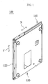
- FIG. 1 is a perspective view illustrating a dual slider assembly in accordance with one embodiment of the present invention.
- FIG. 2 is an exploded perspective view of the dual slider assembly shown in FIG. 1 .
- FIG. 3 is a front view of the dual slider assembly shown in FIG. 1 .
- FIG. 4 is a front view illustrating the state in which the dual slider assembly according to the present invention is slid in a first sliding direction (an X-axis direction).
- FIG. 5 is a front view illustrating the state in which the dual slider assembly according to the present invention is slid in a second sliding direction (a Y-axis direction).
- FIG. 6 is an exploded perspective view of a conventional dual slider assembly.
- FIG. 1 is a perspective view illustrating a dual slider assembly in accordance with one embodiment of the present invention
- FIG. 2 is an exploded perspective view of the dual slider assembly shown in FIG. 1 .
- a dual slider assembly 100 includes a fixed plate 110 , a first sliding plate 120 which is coupled to the fixed plate 110 to be slidable in an X-axis direction, and a second sliding plate 130 which is coupled to the first sliding plate 120 to be slidable in a Y-axis direction.
- These respective plates are manufactured by pressing or injection-molding a metallic material.
- a pair of first guide parts 111 are formed by being bent twice on both lengthwise ends of the fixed plate 110 which are parallel to the X-axis, such that a pair of first guide grooves 111 b are defined in the pair of first guide parts 111 to face each other.
- a fixed pin hole 113 is defined through the fixed plate 110 between the pair of first guide parts 111 .
- a first stopper 112 is formed on the fixed plate 110 to project inward so as to restrict the sliding distance of the first sliding plate 120 .
- Bearing members 114 made of synthetic resin are respectively fitted into the pair of first guide grooves 111 b which are defined by bending the pair of first guide parts 111 .
- Grooves 114 a are defined in the bearing members 114 to extend in the lengthwise direction of the bearing members 114 .
- Engagement parts 111 a are formed on the opposite ends of the upper first guide part 111 of the fixed plate 110 and are bent to project toward the first sliding plate 120 .
- the engagement parts 111 a are to prevent the second sliding plate 130 from sliding in the Y-axis direction while the first sliding plate 120 slides in the X-axis direction.
- First wing parts 122 are formed on the opposite lengthwise ends of the first sliding plate 120 parallel to the X-axis and are bent twice toward the fixed plate 110 .
- the first wing parts 122 are slidably inserted into the grooves 114 a of the bearing members 114 .
- a pair of second guide parts 121 are formed on the opposite widthwise ends of the first sliding plate 120 parallel to the Y-axis and are bent twice in a direction opposite to the direction in which the first wing parts 122 are bent.
- a pair of second guide grooves 121 a are defined in the pair of second guide parts 121 to face each other.
- Bearing members 126 are respectively fitted into the second guide grooves 121 a, and grooves 126 a are defined in the bearing members 126 to extend in the lengthwise direction of the bearing members 126 .
- a guide slot 123 a is defined through the first sliding plate 120 between the pair of second guide parts 121 to extend parallel to the Y-axis and have a predetermined length.
- An accommodating part 123 is formed in a portion of the first sliding plate 120 which includes the guide slot 123 a, such that the accommodating part 123 is depressed in the projecting direction of the second guide parts 121 so as to secure a space for accommodating an elastic means 140 to be installed between the fixed plate 110 and the first sliding plate 120 .
- a second projection 125 for restricting the sliding distance of the first sliding plate 120 in the X-axis direction is formed on the surface of the first sliding plate 120 which faces the fixed plate 110 , at the position corresponding to the first stopper 112 of the fixed plate 110 .
- a first projection 124 for restricting the sliding distance of the second sliding plate 130 in the Y-axis direction is formed on the surface of the first sliding plate 120 which faces the second sliding plate 130 .
- Second wing parts 131 are formed on the opposite widthwise ends of the second sliding plate 130 parallel to the Y-axis and are bent twice toward the first sliding plate 120 .
- the second wing parts 131 are slidably inserted into the grooves 126 a which are defined in the bearing members 126 fitted into the second guide grooves 121 a of the first sliding plate 120 .
- a movable pin hole 134 is defined through the second sliding plate 130 between the pair of second wing parts 131 at the position corresponding to the guide slot 123 a.
- An upper stopper 132 and a lower stopper 133 are formed on the second sliding plate 130 at the position corresponding to the first projection 124 of the first sliding plate 120 to project toward the first sliding plate 120 so as to restrict the sliding distance of the second sliding plate 130 in the Y-axis direction.
- a single elastic member 140 is installed in order to semiautomatically perform the sliding of the first sliding plate 120 in the X-axis direction and the sliding of the second sliding plate 130 in the Y-axis direction.
- the elastic member 140 is composed of a first link slider 141 and a second link slider 142 which are coupled to each other to be slidable in the lengthwise direction thereof, and a plurality of springs 143 which are connected between the first and second link sliders 141 and 142 to apply an elastic returning force to the respective link sliders 141 and 142 .
- One end of the first link slider 141 is pivotably secured to the fixed pin hole 113 of the fixed plate 110 by a fixed pin H 1 .
- One end of the second link slider 142 is pivotably secured to a movable pin H 2 .
- One end of the movable pin H 2 passes through the guide slot 123 a of the first sliding plate 120 and is pivotably secured to the movable pin hole 134 of the second sliding plate 130 .
- the elastic member 140 is installed between the fixed plate 110 and the accommodating part 123 of the first sliding plate 120 to have a slim configuration.
- FIG. 3 is a front view illustrating the assembled state of the dual slider assembly according to the present embodiment. If an external force is applied to the first sliding plate 120 relative to the fixed plate 110 in the leftward direction, the first wing parts 122 of the first sliding plate 120 slide in the direction indicated by an arrow in FIG. 4 (the X-axis direction) while guided by the first guide parts 111 of the fixed plate 110 . At this time, the elastic member 140 contracts and pivots clockwise as shown in FIG. 4 . As the elastic member 140 expands after passing through a maximum contraction point, the first sliding plate 120 continues to slide by the returning force of the springs 143 even without further applying an external force. The sliding movement of the first sliding plate 120 is stopped when the second projection 125 engages with the first stopper 112 .
- the second sliding plate 130 slides in the upward direction (the Y-axis direction) while guided by the second guide parts 121 of the first sliding plate 120 .
- the elastic member 140 contracts and pivots counterclockwise as shown in FIG. 5 .
- the second sliding plate 130 continues to slide by the returning force of the springs 143 even without further applying an external force.
- the sliding movement of the second sliding plate 130 is stopped when the lower stopper 133 engages with the first projection 124 .
- the dual slider assembly in accordance with the present invention is capable of performing semiautomatic bidirectional sliding operation using a single elastic means.
- the dual slider assembly can find its application in the field of mobile phones and so forth.
Landscapes
- Engineering & Computer Science (AREA)
- Signal Processing (AREA)
- Computer Networks & Wireless Communication (AREA)
- Telephone Set Structure (AREA)
Abstract
A dual slider assembly for a mobile phone is provided which can perform semiautomatic bidirectional sliding operation using a single spring mechanism. The dual slider assembly includes a fixed plate. A first sliding plate is coupled to the fixed plate for sliding movement in a first sliding direction and is formed with a guide slot parallel to a second sliding direction. A second sliding plate is coupled to the first sliding plate for sliding movement in the second sliding direction. The dual slider assembly further includes an elastic means for applying an elastic force to maintain the first sliding plate and the second sliding plate in a stationary state, the elastic means having a first end pivotably secured to the fixed plate and a second end pivotably secured to the second sliding plate and restrained to slide along the guide slot of the first sliding plate.
Description
- The present invention relates to a dual slider assembly and, more particularly, to a dual slider assembly which can perform semiautomatic bidirectional sliding operation using a single elastic means.
- A slider assembly for a dual slide mobile phone is disclosed in Korean Unexamined Patent Publication No. 10-2006-0045514 published on May 17, 2006 and entitled “Sliding Apparatus for Double Sliding-type Portable Communication Device.” Referring to
FIG. 6 , theslider assembly 50 disclosed in the document includes a firstsliding plate 52 which is coupled to afixed plate 51 to be slidable in a first sliding direction, and a secondsliding plate 53 which is coupled to the firstsliding plate 52 to be slidable in a second sliding direction.Torsion springs fixed plate 51 and the firstsliding plate 52 and between the firstsliding plate 52 and the secondsliding plate 53 such that the first and second slidingplates torsion springs - In the conventional slider assembly for a dual slide mobile phone constructed as mentioned above, elastic members (torsion springs) are installed between the fixed plate and the first sliding plate and between the first and second sliding plates to apply a returning force. Thus, the thickness of the slider assembly is increased, making it difficult to make the mobile phone slim. Furthermore, the number of parts is increased due to the installation of the two elastic members, which leads to increased manufacturing costs, complicated assembling process and reduced productivity.
- It is an object of the present invention to provide a slim dual slider assembly.
- Another object of the present invention is to provide a slider assembly for a dual slide mobile phone that can reduce the number of parts to save material costs and simplify an assembling process.
- These objects are achieved by providing a slider assembly for a dual slide mobile phone that has a novel technical construction in which the slider assembly can be used semiautomatically by enabling a returning force to be applied bidirectionally using a single elastic means.
- According to the present invention, there is provided a dual slider assembly comprising: a fixed plate; a first sliding plate coupled to the fixed plate for sliding movement in a first sliding direction and formed with a guide slot parallel to a second sliding direction; a second sliding plate coupled to the first sliding plate for sliding movement in the second sliding direction; and an elastic means for applying an elastic force to maintain the first sliding plate and the second sliding plate in a stationary state, the elastic means having a first end pivotably secured to the fixed plate and a second end pivotably secured to the second sliding plate and restrained in such a manner as to slide along the guide slot of the first sliding plate.
- The dual slider assembly recited above may further comprise stoppers for restricting sliding movement distances of the first sliding plate and the second sliding plate.
- In the dual slider assembly recited above, the first sliding plate may have an accommodating part formed in a region covering the guide slot so that the elastic means can be received in the accommodating part throughout a pivotal movement range of the elastic means.
- In the dual slider assembly recited above, the fixed plate may have first guide parts at opposite lengthwise ends thereof, the first guide parts being bent twice toward the first sliding plate so as to form first guide grooves along the first sliding direction. The first sliding plate may have first wing parts at opposite lengthwise ends thereof, the first wing parts being bent toward the fixed plate, and second guide parts at opposite widthwise ends thereof, the second guide parts being bent twice toward the second sliding plate so as to form second guide grooves along the second sliding direction. The second sliding plate may have second wing parts at opposite widthwise ends thereof, the second wing parts being bent toward the first sliding plate. The first wing parts of the first sliding plate may be respectively inserted into and slidably restrained by the first guide grooves of the fixed plate, and the second wing parts of the second sliding plate may be respectively inserted into and slidably restrained by the second guide grooves of the first sliding plate.
- The dual slider assembly recited above may further comprise bearing members fitted into a pair of first guide grooves of the fixed plate and a pair of second guide grooves of the first sliding plate to reduce friction generated during sliding movement of the first and second sliding plates.
- In the dual slider assembly recited above, the elastic means may comprise: a movable pin having a first end pivotably secured to the second sliding plate and a second end inserted into the guide slot of the first sliding plate for sliding movement along the guide slot; and an elastic member having a first end pivotably secured to the fixed plate and a second end pivotably secured to the movable pin.
- In the dual slider assembly recited above, the elastic member may comprise: a first link slider having a first end pivotably secured to the fixed plate; a second link slider having a first end slidably coupled to the first link slider and a second end pivotably secured to the movable pin; and a spring connected to the first link slider and the second link slider for applying a returning force in such a direction as to move the first link slider and the second link slider away from each other.
- Thanks to the above features of the present invention, there is provided a dual slider assembly that can be slid bidirectionally by means of a single elastic means. The helps reduce the number of parts, which leads to reduced manufacturing costs, simplified assembling process and increased productivity. Moreover, it becomes possible to make the slider slim.
-
FIG. 1 is a perspective view illustrating a dual slider assembly in accordance with one embodiment of the present invention. -
FIG. 2 is an exploded perspective view of the dual slider assembly shown inFIG. 1 . -
FIG. 3 is a front view of the dual slider assembly shown inFIG. 1 . -
FIG. 4 is a front view illustrating the state in which the dual slider assembly according to the present invention is slid in a first sliding direction (an X-axis direction). -
FIG. 5 is a front view illustrating the state in which the dual slider assembly according to the present invention is slid in a second sliding direction (a Y-axis direction). -
FIG. 6 is an exploded perspective view of a conventional dual slider assembly. - A preferred embodiment of the present invention will now be described in detail with reference to the accompanying drawings.
-
FIG. 1 is a perspective view illustrating a dual slider assembly in accordance with one embodiment of the present invention, andFIG. 2 is an exploded perspective view of the dual slider assembly shown inFIG. 1 . - Referring to
FIG. 1 , adual slider assembly 100 according to the present embodiment includes afixed plate 110, a firstsliding plate 120 which is coupled to thefixed plate 110 to be slidable in an X-axis direction, and a secondsliding plate 130 which is coupled to the first slidingplate 120 to be slidable in a Y-axis direction. These respective plates are manufactured by pressing or injection-molding a metallic material. - Referring to
FIG. 2 , a pair offirst guide parts 111 are formed by being bent twice on both lengthwise ends of thefixed plate 110 which are parallel to the X-axis, such that a pair offirst guide grooves 111 b are defined in the pair offirst guide parts 111 to face each other. Afixed pin hole 113 is defined through thefixed plate 110 between the pair offirst guide parts 111. Afirst stopper 112 is formed on thefixed plate 110 to project inward so as to restrict the sliding distance of the firstsliding plate 120.Bearing members 114 made of synthetic resin are respectively fitted into the pair offirst guide grooves 111 b which are defined by bending the pair offirst guide parts 111.Grooves 114 a are defined in the bearingmembers 114 to extend in the lengthwise direction of the bearingmembers 114.Engagement parts 111 a are formed on the opposite ends of the upperfirst guide part 111 of thefixed plate 110 and are bent to project toward the firstsliding plate 120. Theengagement parts 111 a are to prevent the second slidingplate 130 from sliding in the Y-axis direction while the firstsliding plate 120 slides in the X-axis direction. -
First wing parts 122 are formed on the opposite lengthwise ends of the firstsliding plate 120 parallel to the X-axis and are bent twice toward thefixed plate 110. Thefirst wing parts 122 are slidably inserted into thegrooves 114 a of the bearingmembers 114. A pair ofsecond guide parts 121 are formed on the opposite widthwise ends of the firstsliding plate 120 parallel to the Y-axis and are bent twice in a direction opposite to the direction in which thefirst wing parts 122 are bent. As thesecond guide parts 121 are bent twice, a pair ofsecond guide grooves 121 a are defined in the pair ofsecond guide parts 121 to face each other.Bearing members 126 are respectively fitted into thesecond guide grooves 121 a, andgrooves 126 a are defined in thebearing members 126 to extend in the lengthwise direction of the bearingmembers 126. Aguide slot 123 a is defined through the firstsliding plate 120 between the pair ofsecond guide parts 121 to extend parallel to the Y-axis and have a predetermined length. Anaccommodating part 123 is formed in a portion of the firstsliding plate 120 which includes theguide slot 123 a, such that theaccommodating part 123 is depressed in the projecting direction of thesecond guide parts 121 so as to secure a space for accommodating anelastic means 140 to be installed between thefixed plate 110 and the firstsliding plate 120. Asecond projection 125 for restricting the sliding distance of the firstsliding plate 120 in the X-axis direction is formed on the surface of the firstsliding plate 120 which faces thefixed plate 110, at the position corresponding to thefirst stopper 112 of thefixed plate 110. Afirst projection 124 for restricting the sliding distance of the secondsliding plate 130 in the Y-axis direction is formed on the surface of the firstsliding plate 120 which faces the secondsliding plate 130. -
Second wing parts 131 are formed on the opposite widthwise ends of the secondsliding plate 130 parallel to the Y-axis and are bent twice toward the first slidingplate 120. Thesecond wing parts 131 are slidably inserted into thegrooves 126 a which are defined in the bearingmembers 126 fitted into thesecond guide grooves 121 a of the firstsliding plate 120. Amovable pin hole 134 is defined through the secondsliding plate 130 between the pair ofsecond wing parts 131 at the position corresponding to theguide slot 123 a. Anupper stopper 132 and alower stopper 133 are formed on the secondsliding plate 130 at the position corresponding to thefirst projection 124 of the firstsliding plate 120 to project toward the firstsliding plate 120 so as to restrict the sliding distance of the secondsliding plate 130 in the Y-axis direction. - Referring again to
FIG. 2 , a singleelastic member 140 is installed in order to semiautomatically perform the sliding of the firstsliding plate 120 in the X-axis direction and the sliding of the secondsliding plate 130 in the Y-axis direction. Theelastic member 140 is composed of afirst link slider 141 and asecond link slider 142 which are coupled to each other to be slidable in the lengthwise direction thereof, and a plurality ofsprings 143 which are connected between the first andsecond link sliders respective link sliders first link slider 141 is pivotably secured to thefixed pin hole 113 of thefixed plate 110 by a fixed pin H1. One end of thesecond link slider 142 is pivotably secured to a movable pin H2. One end of the movable pin H2 passes through theguide slot 123 a of the firstsliding plate 120 and is pivotably secured to themovable pin hole 134 of the secondsliding plate 130. Theelastic member 140 is installed between thefixed plate 110 and theaccommodating part 123 of the first slidingplate 120 to have a slim configuration. - Hereinafter, the operation of the dual slider assembly according to the present embodiment will be described with reference to
FIGS. 3 through 5 . -
FIG. 3 is a front view illustrating the assembled state of the dual slider assembly according to the present embodiment. If an external force is applied to the first slidingplate 120 relative to the fixedplate 110 in the leftward direction, thefirst wing parts 122 of the first slidingplate 120 slide in the direction indicated by an arrow inFIG. 4 (the X-axis direction) while guided by thefirst guide parts 111 of the fixedplate 110. At this time, theelastic member 140 contracts and pivots clockwise as shown inFIG. 4 . As theelastic member 140 expands after passing through a maximum contraction point, the first slidingplate 120 continues to slide by the returning force of thesprings 143 even without further applying an external force. The sliding movement of the first slidingplate 120 is stopped when thesecond projection 125 engages with thefirst stopper 112. - Referring to
FIG. 5 , if an external force is applied to the second slidingplate 130 relative to the fixedplate 110 in the upward direction, the second slidingplate 130 slides in the upward direction (the Y-axis direction) while guided by thesecond guide parts 121 of the first slidingplate 120. At this time, theelastic member 140 contracts and pivots counterclockwise as shown inFIG. 5 . As theelastic member 140 expands after passing through a maximum contraction point, the second slidingplate 130 continues to slide by the returning force of thesprings 143 even without further applying an external force. The sliding movement of the second slidingplate 130 is stopped when thelower stopper 133 engages with thefirst projection 124. - The embodiment shown and described hereinabove should not be construed to limit the scope of protection of the present invention. The scope of the invention shall be limited only by the subject matters recited in the claims. It will be understood by those skilled in the art that various changes and modifications may be made without departing from the scope of the invention defined in the claims.
- The dual slider assembly in accordance with the present invention is capable of performing semiautomatic bidirectional sliding operation using a single elastic means. The dual slider assembly can find its application in the field of mobile phones and so forth.
Claims (10)
1. A dual slider assembly comprising:
a fixed plate;
a first sliding plate coupled to the fixed plate for sliding movement in a first sliding direction and formed with a guide slot parallel to a second sliding direction;
a second sliding plate coupled to the first sliding plate for sliding movement in the second sliding direction; and
an elastic means for applying an elastic force to maintain the first sliding plate and the second sliding plate in a stationary state, the elastic means having a first end pivotably secured to the fixed plate and a second end pivotably secured to the second sliding plate and restrained in such a manner as to slide along the guide slot of the first sliding plate.
2. The dual slider assembly as recited in claim 1 , further comprising:
stoppers for restricting sliding movement distances of the first sliding plate and the second sliding plate.
3. The dual slider assembly as recited in claim 1 , wherein the first sliding plate has an accommodating part formed in a region covering the guide slot so that the elastic means can be received in the accommodating part throughout a pivotal movement range of the elastic means.
4. The dual slider assembly as recited in claim 3 , wherein the fixed plate has first guide parts at opposite lengthwise ends thereof, the first guide parts being bent twice toward the first sliding plate so as to form first guide grooves along the first sliding direction;
wherein the first sliding plate has first wing parts at opposite lengthwise ends thereof, the first wing parts being bent toward the fixed plate, and second guide parts at opposite widthwise ends thereof, the second guide parts being bent twice toward the second sliding plate so as to form second guide grooves along the second sliding direction;
wherein the second sliding plate has second wing parts at opposite widthwise ends thereof, the second wing parts being bent toward the first sliding plate; and
wherein the first wing parts of the first sliding plate are respectively inserted into and slidably restrained by the first guide grooves of the fixed plate, and the second wing parts of the second sliding plate are respectively inserted into and slidably restrained by the second guide grooves of the first sliding plate.
5. The dual slider assembly as recited in claim 4 , further comprising: bearing members fitted into a pair of first guide grooves of the fixed plate and a pair of second guide grooves of the first sliding plate to reduce friction generated during sliding movement of the first and second sliding plates.
6. The dual slider assembly as recited in claim 1 , wherein the elastic means comprises:
a movable pin having a first end pivotably secured to the second sliding plate and a second end inserted into the guide slot of the first sliding plate for sliding movement along the guide slot; and
an elastic member having a first end pivotably secured to the fixed plate and a second end pivotably secured to the movable pin.
7. The dual slider assembly as recited in claim 6 , wherein the elastic member comprises:
a first link slider having a first end pivotably secured to the fixed plate;
a second link slider having a first end slidably coupled to the first link slider and a second end pivotably secured to the movable pin; and
a spring connected to the first link slider and the second link slider for applying a returning force in such a direction as to move the first link slider and the second link slider away from each other.
8. The dual slider assembly as recited in claim 3 , wherein the elastic means comprises:
a movable pin having a first end pivotably secured to the second sliding plate and a second end inserted into the guide slot of the first sliding plate for sliding movement along the guide slot; and
an elastic member having a first end pivotably secured to the fixed plate and a second end pivotably secured to the movable pin.
9. The dual slider assembly as recited in claim 4 , wherein the elastic means comprises:
a movable pin having a first end pivotably secured to the second sliding plate and a second end inserted into the guide slot of the first sliding plate for sliding movement along the guide slot; and
an elastic member having a first end pivotably secured to the fixed plate and a second end pivotably secured to the movable pin.
10. The dual slider assembly as recited in claim 9 , wherein the elastic member comprises:
a first link slider having a first end pivotably secured to the fixed plate;
a second link slider having a first end slidably coupled to the first link slider and a second end pivotably secured to the movable pin; and
a spring connected to the first link slider and the second link slider for applying a returning force in such a direction as to move the first link slider and the second link slider away from each other.
Applications Claiming Priority (3)
| Application Number | Priority Date | Filing Date | Title |
|---|---|---|---|
| KR1020070051730A KR100867664B1 (en) | 2007-05-28 | 2007-05-28 | Dual slider assembly |
| KR10-2007-0051730 | 2007-05-28 | ||
| PCT/KR2008/002860 WO2008147074A2 (en) | 2007-05-28 | 2008-05-22 | Dual slider assembly |
Publications (1)
| Publication Number | Publication Date |
|---|---|
| US20100180712A1 true US20100180712A1 (en) | 2010-07-22 |
Family
ID=40075652
Family Applications (1)
| Application Number | Title | Priority Date | Filing Date |
|---|---|---|---|
| US12/602,132 Abandoned US20100180712A1 (en) | 2007-05-28 | 2008-05-22 | Dual slider assembly |
Country Status (4)
| Country | Link |
|---|---|
| US (1) | US20100180712A1 (en) |
| KR (1) | KR100867664B1 (en) |
| CN (1) | CN101730976A (en) |
| WO (1) | WO2008147074A2 (en) |
Families Citing this family (3)
| Publication number | Priority date | Publication date | Assignee | Title |
|---|---|---|---|---|
| WO2009002103A2 (en) * | 2007-06-26 | 2008-12-31 | Mtx Hybrid Co., Ltd. | Sliding module and sliding device having the same |
| JP2011015181A (en) | 2009-07-02 | 2011-01-20 | Funai Electric Co Ltd | Portable terminal device |
| KR101104952B1 (en) * | 2009-08-19 | 2012-01-12 | 주식회사 다이아벨 | Sliding Apparatus and Electronic Appliance having it |
Citations (4)
| Publication number | Priority date | Publication date | Assignee | Title |
|---|---|---|---|---|
| US7422436B2 (en) * | 2005-10-12 | 2008-09-09 | Lg Electronics Inc. | Slide module having dual movement and mobile terminal having the same |
| US7778663B2 (en) * | 2006-04-24 | 2010-08-17 | Virgin Mobile Usa, L.P. | Hinge module for three-step open type portable terminal and portable terminal having the same |
| US7925317B2 (en) * | 2005-10-11 | 2011-04-12 | Samsung Electronics Co., Ltd. | Keypad, sliding module and sliding module flexible circuit for portable terminal |
| US8060166B2 (en) * | 2008-01-11 | 2011-11-15 | Katoh Electrical Machinery Co., Ltd. | Slide mechanism of portable equipment and portable equipment |
Family Cites Families (7)
| Publication number | Priority date | Publication date | Assignee | Title |
|---|---|---|---|---|
| JP4252004B2 (en) * | 2004-03-17 | 2009-04-08 | 加藤電機株式会社 | Semi-automatic slide device |
| KR20070035699A (en) * | 2005-09-28 | 2007-04-02 | 추종철 | Sliding unit and electric device using the same |
| KR100715811B1 (en) * | 2005-05-03 | 2007-05-08 | 엘지전자 주식회사 | Sliding type portable phone |
| KR101143697B1 (en) * | 2005-08-26 | 2012-05-09 | 엘지전자 주식회사 | 2 direction manual slide module for mobile terminal |
| KR100606466B1 (en) * | 2006-04-13 | 2006-08-01 | (주)쉘-라인 | Slide hinge device for cross sliding movement |
| KR200421654Y1 (en) * | 2006-05-02 | 2006-07-18 | (주)나노텍 | Dual slide for game and phone terminal |
| KR100721347B1 (en) * | 2006-05-24 | 2007-05-25 | 주식회사 다이아벨 | Structure hinge of cellular phone |
-
2007
- 2007-05-28 KR KR1020070051730A patent/KR100867664B1/en not_active IP Right Cessation
-
2008
- 2008-05-22 WO PCT/KR2008/002860 patent/WO2008147074A2/en active Application Filing
- 2008-05-22 US US12/602,132 patent/US20100180712A1/en not_active Abandoned
- 2008-05-22 CN CN200880015162A patent/CN101730976A/en active Pending
Patent Citations (4)
| Publication number | Priority date | Publication date | Assignee | Title |
|---|---|---|---|---|
| US7925317B2 (en) * | 2005-10-11 | 2011-04-12 | Samsung Electronics Co., Ltd. | Keypad, sliding module and sliding module flexible circuit for portable terminal |
| US7422436B2 (en) * | 2005-10-12 | 2008-09-09 | Lg Electronics Inc. | Slide module having dual movement and mobile terminal having the same |
| US7778663B2 (en) * | 2006-04-24 | 2010-08-17 | Virgin Mobile Usa, L.P. | Hinge module for three-step open type portable terminal and portable terminal having the same |
| US8060166B2 (en) * | 2008-01-11 | 2011-11-15 | Katoh Electrical Machinery Co., Ltd. | Slide mechanism of portable equipment and portable equipment |
Also Published As
| Publication number | Publication date |
|---|---|
| CN101730976A (en) | 2010-06-09 |
| WO2008147074A3 (en) | 2009-01-29 |
| KR100867664B1 (en) | 2008-11-10 |
| WO2008147074A2 (en) | 2008-12-04 |
Similar Documents
| Publication | Publication Date | Title |
|---|---|---|
| KR100839415B1 (en) | Up/down positioning means for slider assembly and slider assembly for sliding-type mobile phone having the up/down positioning means | |
| US20100022286A1 (en) | Sliding mechanism and portable electronic device using the same | |
| JP2009032098A (en) | Slide mechanism, electronic apparatus and portable device | |
| US7755892B2 (en) | Slide mechanism and slide-type terminal device using the same | |
| KR100678071B1 (en) | Portable terminal with sliding module | |
| KR101117598B1 (en) | Slide module of mobile phone | |
| US8594754B2 (en) | Electronic device | |
| US20100134962A1 (en) | Slide mechanism and slide-type portable electronic device using the same | |
| US20100180712A1 (en) | Dual slider assembly | |
| US8428668B2 (en) | Sliding mechanism | |
| EP2547074B1 (en) | Spring unit and sliding mechanism | |
| KR100800808B1 (en) | Sliding module for sliding type mobile phone | |
| US8208254B2 (en) | Slide mechanism for slide-type portable electronic device | |
| WO2013115059A1 (en) | Spring unit and slide mechanism | |
| JP5923322B2 (en) | Spring unit and slide mechanism | |
| KR100876552B1 (en) | Elasticity lever mechanism for mobile phone | |
| JP3148087U (en) | Slide unit and portable product | |
| KR100970983B1 (en) | Spring module for sliding apparatus | |
| KR100907446B1 (en) | A bi-direicton slide Hinge Apparatus for Mobile Phone | |
| KR200403709Y1 (en) | Up/down positioning means for slider assembly and slider assembly for sliding-type mobile phone having the up/down positioning means | |
| KR101122170B1 (en) | Antenna integrated slide apparatus of mobile equipments | |
| JP5007324B2 (en) | Curve slide mechanism for mobile devices | |
| JP3164371U (en) | Slide device | |
| JP4871931B2 (en) | Sliding mobile terminal | |
| KR20090109656A (en) | Sliding device for use in portable device having sliding cover |
Legal Events
| Date | Code | Title | Description |
|---|---|---|---|
| AS | Assignment |
Owner name: AMPHENOL PHOENIX CO., LTD., KOREA, REPUBLIC OF Free format text: ASSIGNMENT OF ASSIGNORS INTEREST;ASSIGNOR:CHOI, JAE KYU;REEL/FRAME:024139/0104 Effective date: 20091211 |
|
| STCB | Information on status: application discontinuation |
Free format text: ABANDONED -- FAILURE TO RESPOND TO AN OFFICE ACTION |