US20070170843A1 - Organic electroluminescent device and organic electroluminescent display - Google Patents
Organic electroluminescent device and organic electroluminescent display Download PDFInfo
- Publication number
- US20070170843A1 US20070170843A1 US10/590,076 US59007605A US2007170843A1 US 20070170843 A1 US20070170843 A1 US 20070170843A1 US 59007605 A US59007605 A US 59007605A US 2007170843 A1 US2007170843 A1 US 2007170843A1
- Authority
- US
- United States
- Prior art keywords
- layer
- organic electroluminescent
- electroluminescent device
- oxide
- metal
- Prior art date
- Legal status (The legal status is an assumption and is not a legal conclusion. Google has not performed a legal analysis and makes no representation as to the accuracy of the status listed.)
- Abandoned
Links
- 229910044991 metal oxide Inorganic materials 0.000 claims abstract description 81
- 150000004706 metal oxides Chemical class 0.000 claims abstract description 81
- 229910052751 metal Inorganic materials 0.000 claims abstract description 41
- 239000002184 metal Substances 0.000 claims abstract description 41
- 239000000758 substrate Substances 0.000 claims abstract description 37
- 230000000737 periodic effect Effects 0.000 claims abstract description 5
- JKQOBWVOAYFWKG-UHFFFAOYSA-N molybdenum trioxide Inorganic materials O=[Mo](=O)=O JKQOBWVOAYFWKG-UHFFFAOYSA-N 0.000 claims description 19
- 229910052783 alkali metal Inorganic materials 0.000 claims description 14
- 150000001340 alkali metals Chemical class 0.000 claims description 14
- 229910052792 caesium Inorganic materials 0.000 claims description 14
- 229910052784 alkaline earth metal Inorganic materials 0.000 claims description 13
- 150000001342 alkaline earth metals Chemical class 0.000 claims description 13
- XLOMVQKBTHCTTD-UHFFFAOYSA-N Zinc monoxide Chemical compound [Zn]=O XLOMVQKBTHCTTD-UHFFFAOYSA-N 0.000 claims description 12
- 229910052708 sodium Inorganic materials 0.000 claims description 11
- 229910052700 potassium Inorganic materials 0.000 claims description 10
- 229910052701 rubidium Inorganic materials 0.000 claims description 9
- 239000004065 semiconductor Substances 0.000 claims description 9
- XHCLAFWTIXFWPH-UHFFFAOYSA-N [O-2].[O-2].[O-2].[O-2].[O-2].[V+5].[V+5] Chemical compound [O-2].[O-2].[O-2].[O-2].[O-2].[V+5].[V+5] XHCLAFWTIXFWPH-UHFFFAOYSA-N 0.000 claims description 8
- 239000012212 insulator Substances 0.000 claims description 8
- 229910052744 lithium Inorganic materials 0.000 claims description 8
- 229910000476 molybdenum oxide Inorganic materials 0.000 claims description 8
- PQQKPALAQIIWST-UHFFFAOYSA-N oxomolybdenum Chemical compound [Mo]=O PQQKPALAQIIWST-UHFFFAOYSA-N 0.000 claims description 8
- 229910052709 silver Inorganic materials 0.000 claims description 8
- 229910052712 strontium Inorganic materials 0.000 claims description 8
- 229910001935 vanadium oxide Inorganic materials 0.000 claims description 8
- 229910045601 alloy Inorganic materials 0.000 claims description 7
- 239000000956 alloy Substances 0.000 claims description 7
- 229910052791 calcium Inorganic materials 0.000 claims description 7
- 150000004767 nitrides Chemical class 0.000 claims description 7
- 229910052749 magnesium Inorganic materials 0.000 claims description 6
- TWNQGVIAIRXVLR-UHFFFAOYSA-N oxo(oxoalumanyloxy)alumane Chemical compound O=[Al]O[Al]=O TWNQGVIAIRXVLR-UHFFFAOYSA-N 0.000 claims description 6
- 239000011787 zinc oxide Substances 0.000 claims description 6
- GWEVSGVZZGPLCZ-UHFFFAOYSA-N Titan oxide Chemical compound O=[Ti]=O GWEVSGVZZGPLCZ-UHFFFAOYSA-N 0.000 claims description 5
- GNTDGMZSJNCJKK-UHFFFAOYSA-N Vanadium(V) oxide Inorganic materials O=[V](=O)O[V](=O)=O GNTDGMZSJNCJKK-UHFFFAOYSA-N 0.000 claims description 5
- WGLPBDUCMAPZCE-UHFFFAOYSA-N chromium trioxide Inorganic materials O=[Cr](=O)=O WGLPBDUCMAPZCE-UHFFFAOYSA-N 0.000 claims description 5
- 229910052738 indium Inorganic materials 0.000 claims description 5
- 229910001925 ruthenium oxide Inorganic materials 0.000 claims description 5
- WOCIAKWEIIZHES-UHFFFAOYSA-N ruthenium(iv) oxide Chemical compound O=[Ru]=O WOCIAKWEIIZHES-UHFFFAOYSA-N 0.000 claims description 5
- 229910052710 silicon Inorganic materials 0.000 claims description 5
- OGIDPMRJRNCKJF-UHFFFAOYSA-N titanium oxide Inorganic materials [Ti]=O OGIDPMRJRNCKJF-UHFFFAOYSA-N 0.000 claims description 5
- 229910052769 Ytterbium Inorganic materials 0.000 claims description 4
- 229910052737 gold Inorganic materials 0.000 claims description 4
- 229910052697 platinum Inorganic materials 0.000 claims description 4
- 229910052725 zinc Inorganic materials 0.000 claims description 4
- 239000011701 zinc Substances 0.000 claims description 4
- 229910052684 Cerium Inorganic materials 0.000 claims description 3
- QPLDLSVMHZLSFG-UHFFFAOYSA-N Copper oxide Chemical compound [Cu]=O QPLDLSVMHZLSFG-UHFFFAOYSA-N 0.000 claims description 3
- 239000005751 Copper oxide Substances 0.000 claims description 3
- 229910052692 Dysprosium Inorganic materials 0.000 claims description 3
- 229910052691 Erbium Inorganic materials 0.000 claims description 3
- 229910052693 Europium Inorganic materials 0.000 claims description 3
- 229910052688 Gadolinium Inorganic materials 0.000 claims description 3
- 229910014704 LixTi2O4 Inorganic materials 0.000 claims description 3
- 229910015062 LixV2O4 Inorganic materials 0.000 claims description 3
- 229910052779 Neodymium Inorganic materials 0.000 claims description 3
- 229910052777 Praseodymium Inorganic materials 0.000 claims description 3
- 229910052772 Samarium Inorganic materials 0.000 claims description 3
- 229910052771 Terbium Inorganic materials 0.000 claims description 3
- 229910010252 TiO3 Inorganic materials 0.000 claims description 3
- 229910052797 bismuth Inorganic materials 0.000 claims description 3
- 229910052804 chromium Inorganic materials 0.000 claims description 3
- 229910000431 copper oxide Inorganic materials 0.000 claims description 3
- 229910052732 germanium Inorganic materials 0.000 claims description 3
- 229910000449 hafnium oxide Inorganic materials 0.000 claims description 3
- WIHZLLGSGQNAGK-UHFFFAOYSA-N hafnium(4+);oxygen(2-) Chemical compound [O-2].[O-2].[Hf+4] WIHZLLGSGQNAGK-UHFFFAOYSA-N 0.000 claims description 3
- 229910052741 iridium Inorganic materials 0.000 claims description 3
- 229910052745 lead Inorganic materials 0.000 claims description 3
- 229910052748 manganese Inorganic materials 0.000 claims description 3
- 229910052750 molybdenum Inorganic materials 0.000 claims description 3
- 229910052759 nickel Inorganic materials 0.000 claims description 3
- QGLKJKCYBOYXKC-UHFFFAOYSA-N nonaoxidotritungsten Chemical compound O=[W]1(=O)O[W](=O)(=O)O[W](=O)(=O)O1 QGLKJKCYBOYXKC-UHFFFAOYSA-N 0.000 claims description 3
- SIWVEOZUMHYXCS-UHFFFAOYSA-N oxo(oxoyttriooxy)yttrium Chemical compound O=[Y]O[Y]=O SIWVEOZUMHYXCS-UHFFFAOYSA-N 0.000 claims description 3
- DYIZHKNUQPHNJY-UHFFFAOYSA-N oxorhenium Chemical compound [Re]=O DYIZHKNUQPHNJY-UHFFFAOYSA-N 0.000 claims description 3
- 229910052763 palladium Inorganic materials 0.000 claims description 3
- 229910003449 rhenium oxide Inorganic materials 0.000 claims description 3
- 229910052718 tin Inorganic materials 0.000 claims description 3
- 239000011135 tin Substances 0.000 claims description 3
- 239000010936 titanium Substances 0.000 claims description 3
- 229910052719 titanium Inorganic materials 0.000 claims description 3
- 229910052721 tungsten Inorganic materials 0.000 claims description 3
- 229910001930 tungsten oxide Inorganic materials 0.000 claims description 3
- 229910052720 vanadium Inorganic materials 0.000 claims description 3
- 229910052726 zirconium Inorganic materials 0.000 claims description 3
- -1 polyethylene terephthalate Polymers 0.000 description 687
- 239000010410 layer Substances 0.000 description 288
- 239000010408 film Substances 0.000 description 58
- 125000004432 carbon atom Chemical group C* 0.000 description 45
- 239000000463 material Substances 0.000 description 41
- 125000003118 aryl group Chemical group 0.000 description 27
- 238000000034 method Methods 0.000 description 25
- 238000001771 vacuum deposition Methods 0.000 description 25
- 238000000151 deposition Methods 0.000 description 24
- 230000008021 deposition Effects 0.000 description 24
- 150000001875 compounds Chemical class 0.000 description 21
- 125000001424 substituent group Chemical group 0.000 description 18
- 125000001997 phenyl group Chemical group [H]C1=C([H])C([H])=C(*)C([H])=C1[H] 0.000 description 16
- 125000000217 alkyl group Chemical group 0.000 description 13
- 238000004528 spin coating Methods 0.000 description 13
- 239000010409 thin film Substances 0.000 description 13
- 125000003545 alkoxy group Chemical group 0.000 description 12
- 238000004544 sputter deposition Methods 0.000 description 12
- 239000002019 doping agent Substances 0.000 description 11
- 125000000623 heterocyclic group Chemical group 0.000 description 10
- 239000011734 sodium Substances 0.000 description 10
- KFZMGEQAYNKOFK-UHFFFAOYSA-N Isopropanol Chemical compound CC(C)O KFZMGEQAYNKOFK-UHFFFAOYSA-N 0.000 description 9
- GVEPBJHOBDJJJI-UHFFFAOYSA-N fluoranthene Chemical compound C1=CC(C2=CC=CC=C22)=C3C2=CC=CC3=C1 GVEPBJHOBDJJJI-UHFFFAOYSA-N 0.000 description 9
- 239000011521 glass Substances 0.000 description 9
- 238000004020 luminiscence type Methods 0.000 description 9
- 239000011575 calcium Substances 0.000 description 8
- 150000004820 halides Chemical class 0.000 description 8
- 125000004104 aryloxy group Chemical group 0.000 description 7
- 125000004435 hydrogen atom Chemical group [H]* 0.000 description 7
- 125000000040 m-tolyl group Chemical group [H]C1=C([H])C(*)=C([H])C(=C1[H])C([H])([H])[H] 0.000 description 7
- 239000011777 magnesium Substances 0.000 description 7
- 125000001637 1-naphthyl group Chemical group [H]C1=C([H])C([H])=C2C(*)=C([H])C([H])=C([H])C2=C1[H] 0.000 description 6
- 125000001622 2-naphthyl group Chemical group [H]C1=C([H])C([H])=C2C([H])=C(*)C([H])=C([H])C2=C1[H] 0.000 description 6
- MWPLVEDNUUSJAV-UHFFFAOYSA-N anthracene Chemical compound C1=CC=CC2=CC3=CC=CC=C3C=C21 MWPLVEDNUUSJAV-UHFFFAOYSA-N 0.000 description 6
- WDECIBYCCFPHNR-UHFFFAOYSA-N chrysene Chemical compound C1=CC=CC2=CC=C3C4=CC=CC=C4C=CC3=C21 WDECIBYCCFPHNR-UHFFFAOYSA-N 0.000 description 6
- NIHNNTQXNPWCJQ-UHFFFAOYSA-N fluorene Chemical compound C1=CC=C2CC3=CC=CC=C3C2=C1 NIHNNTQXNPWCJQ-UHFFFAOYSA-N 0.000 description 6
- 125000005843 halogen group Chemical group 0.000 description 6
- 150000002430 hydrocarbons Chemical group 0.000 description 6
- PQXKHYXIUOZZFA-UHFFFAOYSA-M lithium fluoride Chemical compound [Li+].[F-] PQXKHYXIUOZZFA-UHFFFAOYSA-M 0.000 description 6
- 125000002496 methyl group Chemical group [H]C([H])([H])* 0.000 description 6
- 125000003261 o-tolyl group Chemical group [H]C1=C([H])C(*)=C(C([H])=C1[H])C([H])([H])[H] 0.000 description 6
- 125000001037 p-tolyl group Chemical group [H]C1=C([H])C(=C([H])C([H])=C1*)C([H])([H])[H] 0.000 description 6
- YNPNZTXNASCQKK-UHFFFAOYSA-N phenanthrene Chemical compound C1=CC=C2C3=CC=CC=C3C=CC2=C1 YNPNZTXNASCQKK-UHFFFAOYSA-N 0.000 description 6
- BBEAQIROQSPTKN-UHFFFAOYSA-N pyrene Chemical compound C1=CC=C2C=CC3=CC=CC4=CC=C1C2=C43 BBEAQIROQSPTKN-UHFFFAOYSA-N 0.000 description 6
- 229920006395 saturated elastomer Polymers 0.000 description 6
- 239000000126 substance Substances 0.000 description 6
- 238000007740 vapor deposition Methods 0.000 description 6
- 125000003277 amino group Chemical group 0.000 description 5
- 125000004093 cyano group Chemical group *C#N 0.000 description 5
- 238000002347 injection Methods 0.000 description 5
- 239000007924 injection Substances 0.000 description 5
- 125000001624 naphthyl group Chemical group 0.000 description 5
- 239000012044 organic layer Substances 0.000 description 5
- MCJGNVYPOGVAJF-UHFFFAOYSA-N quinolin-8-ol Chemical compound C1=CN=C2C(O)=CC=CC2=C1 MCJGNVYPOGVAJF-UHFFFAOYSA-N 0.000 description 5
- 229910052761 rare earth metal Inorganic materials 0.000 description 5
- 150000002910 rare earth metals Chemical class 0.000 description 5
- MNCMBBIFTVWHIP-UHFFFAOYSA-N 1-anthracen-9-yl-2,2,2-trifluoroethanone Chemical group C1=CC=C2C(C(=O)C(F)(F)F)=C(C=CC=C3)C3=CC2=C1 MNCMBBIFTVWHIP-UHFFFAOYSA-N 0.000 description 4
- YTPLMLYBLZKORZ-UHFFFAOYSA-N Thiophene Chemical compound C=1C=CSC=1 YTPLMLYBLZKORZ-UHFFFAOYSA-N 0.000 description 4
- 125000002078 anthracen-1-yl group Chemical group [H]C1=C([H])C([H])=C2C([H])=C3C([*])=C([H])C([H])=C([H])C3=C([H])C2=C1[H] 0.000 description 4
- 125000000748 anthracen-2-yl group Chemical group [H]C1=C([H])C([H])=C2C([H])=C3C([H])=C([*])C([H])=C([H])C3=C([H])C2=C1[H] 0.000 description 4
- 125000004429 atom Chemical group 0.000 description 4
- 230000015572 biosynthetic process Effects 0.000 description 4
- 230000000052 comparative effect Effects 0.000 description 4
- ZUOUZKKEUPVFJK-UHFFFAOYSA-N diphenyl Chemical compound C1=CC=CC=C1C1=CC=CC=C1 ZUOUZKKEUPVFJK-UHFFFAOYSA-N 0.000 description 4
- 230000005684 electric field Effects 0.000 description 4
- 125000001495 ethyl group Chemical group [H]C([H])([H])C([H])([H])* 0.000 description 4
- 239000010931 gold Substances 0.000 description 4
- 125000001072 heteroaryl group Chemical group 0.000 description 4
- 238000004519 manufacturing process Methods 0.000 description 4
- 125000000449 nitro group Chemical group [O-][N+](*)=O 0.000 description 4
- 229960003540 oxyquinoline Drugs 0.000 description 4
- 125000002080 perylenyl group Chemical group C1(=CC=C2C=CC=C3C4=CC=CC5=CC=CC(C1=C23)=C45)* 0.000 description 4
- BASFCYQUMIYNBI-UHFFFAOYSA-N platinum Substances [Pt] BASFCYQUMIYNBI-UHFFFAOYSA-N 0.000 description 4
- 125000001436 propyl group Chemical group [H]C([*])([H])C([H])([H])C([H])([H])[H] 0.000 description 4
- 125000003373 pyrazinyl group Chemical group 0.000 description 4
- 229930195734 saturated hydrocarbon Natural products 0.000 description 4
- 125000002914 sec-butyl group Chemical group [H]C([H])([H])C([H])([H])C([H])(*)C([H])([H])[H] 0.000 description 4
- VYPSYNLAJGMNEJ-UHFFFAOYSA-N silicon dioxide Inorganic materials O=[Si]=O VYPSYNLAJGMNEJ-UHFFFAOYSA-N 0.000 description 4
- 125000005504 styryl group Chemical group 0.000 description 4
- 125000000999 tert-butyl group Chemical group [H]C([H])([H])C(*)(C([H])([H])[H])C([H])([H])[H] 0.000 description 4
- 229930195735 unsaturated hydrocarbon Natural products 0.000 description 4
- 229920002554 vinyl polymer Polymers 0.000 description 4
- YCEZZDNWLVQCRU-UHFFFAOYSA-N 1,2-diaminoethyl Chemical group N[CH]CN YCEZZDNWLVQCRU-UHFFFAOYSA-N 0.000 description 3
- LLAPDLPYIYKTGQ-UHFFFAOYSA-N 1-aminoethyl Chemical group C[CH]N LLAPDLPYIYKTGQ-UHFFFAOYSA-N 0.000 description 3
- 125000006083 1-bromoethyl group Chemical group 0.000 description 3
- 125000001478 1-chloroethyl group Chemical group [H]C([H])([H])C([H])(Cl)* 0.000 description 3
- 125000004066 1-hydroxyethyl group Chemical group [H]OC([H])([*])C([H])([H])[H] 0.000 description 3
- 125000000022 2-aminoethyl group Chemical group [H]C([*])([H])C([H])([H])N([H])[H] 0.000 description 3
- 125000005999 2-bromoethyl group Chemical group 0.000 description 3
- 125000001340 2-chloroethyl group Chemical group [H]C([H])(Cl)C([H])([H])* 0.000 description 3
- 125000001731 2-cyanoethyl group Chemical group [H]C([H])(*)C([H])([H])C#N 0.000 description 3
- 125000002941 2-furyl group Chemical group O1C([*])=C([H])C([H])=C1[H] 0.000 description 3
- 125000000954 2-hydroxyethyl group Chemical group [H]C([*])([H])C([H])([H])O[H] 0.000 description 3
- 125000000389 2-pyrrolyl group Chemical group [H]N1C([*])=C([H])C([H])=C1[H] 0.000 description 3
- 125000000175 2-thienyl group Chemical group S1C([*])=C([H])C([H])=C1[H] 0.000 description 3
- 125000003682 3-furyl group Chemical group O1C([H])=C([*])C([H])=C1[H] 0.000 description 3
- 125000001397 3-pyrrolyl group Chemical group [H]N1C([H])=C([*])C([H])=C1[H] 0.000 description 3
- 125000001541 3-thienyl group Chemical group S1C([H])=C([*])C([H])=C1[H] 0.000 description 3
- 239000005725 8-Hydroxyquinoline Substances 0.000 description 3
- ODINCKMPIJJUCX-UHFFFAOYSA-N Calcium oxide Chemical compound [Ca]=O ODINCKMPIJJUCX-UHFFFAOYSA-N 0.000 description 3
- CBENFWSGALASAD-UHFFFAOYSA-N Ozone Chemical compound [O-][O+]=O CBENFWSGALASAD-UHFFFAOYSA-N 0.000 description 3
- KPCZJLGGXRGYIE-UHFFFAOYSA-N [C]1=CC=CN=C1 Chemical group [C]1=CC=CN=C1 KPCZJLGGXRGYIE-UHFFFAOYSA-N 0.000 description 3
- 125000003342 alkenyl group Chemical group 0.000 description 3
- 125000004202 aminomethyl group Chemical group [H]N([H])C([H])([H])* 0.000 description 3
- 150000004982 aromatic amines Chemical class 0.000 description 3
- 125000005110 aryl thio group Chemical group 0.000 description 3
- 229910052788 barium Inorganic materials 0.000 description 3
- 125000005997 bromomethyl group Chemical group 0.000 description 3
- 125000003917 carbamoyl group Chemical group [H]N([H])C(*)=O 0.000 description 3
- 229910052799 carbon Inorganic materials 0.000 description 3
- 125000004218 chloromethyl group Chemical group [H]C([H])(Cl)* 0.000 description 3
- 239000013078 crystal Substances 0.000 description 3
- 125000000753 cycloalkyl group Chemical group 0.000 description 3
- 230000007547 defect Effects 0.000 description 3
- 125000005842 heteroatom Chemical group 0.000 description 3
- 125000002887 hydroxy group Chemical group [H]O* 0.000 description 3
- 125000004029 hydroxymethyl group Chemical group [H]OC([H])([H])* 0.000 description 3
- 125000000959 isobutyl group Chemical group [H]C([H])([H])C([H])(C([H])([H])[H])C([H])([H])* 0.000 description 3
- 125000001449 isopropyl group Chemical group [H]C([H])([H])C([H])(*)C([H])([H])[H] 0.000 description 3
- 239000003446 ligand Substances 0.000 description 3
- 150000002736 metal compounds Chemical class 0.000 description 3
- 239000000203 mixture Substances 0.000 description 3
- 125000004108 n-butyl group Chemical group [H]C([H])([H])C([H])([H])C([H])([H])C([H])([H])* 0.000 description 3
- 125000003136 n-heptyl group Chemical group [H]C([H])([H])C([H])([H])C([H])([H])C([H])([H])C([H])([H])C([H])([H])C([H])([H])* 0.000 description 3
- 125000001280 n-hexyl group Chemical group C(CCCCC)* 0.000 description 3
- 125000000740 n-pentyl group Chemical group [H]C([H])([H])C([H])([H])C([H])([H])C([H])([H])C([H])([H])* 0.000 description 3
- 229910052757 nitrogen Inorganic materials 0.000 description 3
- 125000003808 silyl group Chemical group [H][Si]([H])([H])[*] 0.000 description 3
- 238000004506 ultrasonic cleaning Methods 0.000 description 3
- ZCYVEMRRCGMTRW-UHFFFAOYSA-N 7553-56-2 Chemical compound [I] ZCYVEMRRCGMTRW-UHFFFAOYSA-N 0.000 description 2
- 229910052582 BN Inorganic materials 0.000 description 2
- PZNSFCLAULLKQX-UHFFFAOYSA-N Boron nitride Chemical compound N#B PZNSFCLAULLKQX-UHFFFAOYSA-N 0.000 description 2
- WKBOTKDWSSQWDR-UHFFFAOYSA-N Bromine atom Chemical compound [Br] WKBOTKDWSSQWDR-UHFFFAOYSA-N 0.000 description 2
- ZAMOUSCENKQFHK-UHFFFAOYSA-N Chlorine atom Chemical compound [Cl] ZAMOUSCENKQFHK-UHFFFAOYSA-N 0.000 description 2
- PXGOKWXKJXAPGV-UHFFFAOYSA-N Fluorine Chemical compound FF PXGOKWXKJXAPGV-UHFFFAOYSA-N 0.000 description 2
- 229910000733 Li alloy Inorganic materials 0.000 description 2
- FUJCRWPEOMXPAD-UHFFFAOYSA-N Li2O Inorganic materials [Li+].[Li+].[O-2] FUJCRWPEOMXPAD-UHFFFAOYSA-N 0.000 description 2
- FYYHWMGAXLPEAU-UHFFFAOYSA-N Magnesium Chemical compound [Mg] FYYHWMGAXLPEAU-UHFFFAOYSA-N 0.000 description 2
- 229910000861 Mg alloy Inorganic materials 0.000 description 2
- KWYHDKDOAIKMQN-UHFFFAOYSA-N N,N,N',N'-tetramethylethylenediamine Chemical compound CN(C)CCN(C)C KWYHDKDOAIKMQN-UHFFFAOYSA-N 0.000 description 2
- 229920001774 Perfluoroether Polymers 0.000 description 2
- WCUXLLCKKVVCTQ-UHFFFAOYSA-M Potassium chloride Chemical compound [Cl-].[K+] WCUXLLCKKVVCTQ-UHFFFAOYSA-M 0.000 description 2
- 229910052581 Si3N4 Inorganic materials 0.000 description 2
- FAPWRFPIFSIZLT-UHFFFAOYSA-M Sodium chloride Chemical compound [Na+].[Cl-] FAPWRFPIFSIZLT-UHFFFAOYSA-M 0.000 description 2
- SLGBZMMZGDRARJ-UHFFFAOYSA-N Triphenylene Natural products C1=CC=C2C3=CC=CC=C3C3=CC=CC=C3C2=C1 SLGBZMMZGDRARJ-UHFFFAOYSA-N 0.000 description 2
- 125000004054 acenaphthylenyl group Chemical group C1(=CC2=CC=CC3=CC=CC1=C23)* 0.000 description 2
- HXGDTGSAIMULJN-UHFFFAOYSA-N acetnaphthylene Natural products C1=CC(C=C2)=C3C2=CC=CC3=C1 HXGDTGSAIMULJN-UHFFFAOYSA-N 0.000 description 2
- 125000003302 alkenyloxy group Chemical group 0.000 description 2
- 125000004453 alkoxycarbonyl group Chemical group 0.000 description 2
- 125000005194 alkoxycarbonyloxy group Chemical group 0.000 description 2
- 125000004448 alkyl carbonyl group Chemical group 0.000 description 2
- 125000005196 alkyl carbonyloxy group Chemical group 0.000 description 2
- 125000000304 alkynyl group Chemical group 0.000 description 2
- 125000005133 alkynyloxy group Chemical group 0.000 description 2
- 229910052782 aluminium Inorganic materials 0.000 description 2
- XAGFODPZIPBFFR-UHFFFAOYSA-N aluminium Chemical compound [Al] XAGFODPZIPBFFR-UHFFFAOYSA-N 0.000 description 2
- 125000005427 anthranyl group Chemical group 0.000 description 2
- 125000006615 aromatic heterocyclic group Chemical group 0.000 description 2
- 125000003710 aryl alkyl group Chemical group 0.000 description 2
- 125000005129 aryl carbonyl group Chemical group 0.000 description 2
- 125000005199 aryl carbonyloxy group Chemical group 0.000 description 2
- 125000005161 aryl oxy carbonyl group Chemical group 0.000 description 2
- 125000000732 arylene group Chemical group 0.000 description 2
- 125000005200 aryloxy carbonyloxy group Chemical group 0.000 description 2
- 125000000751 azo group Chemical group [*]N=N[*] 0.000 description 2
- CUFNKYGDVFVPHO-UHFFFAOYSA-N azulene Chemical compound C1=CC=CC2=CC=CC2=C1 CUFNKYGDVFVPHO-UHFFFAOYSA-N 0.000 description 2
- DSAJWYNOEDNPEQ-UHFFFAOYSA-N barium atom Chemical compound [Ba] DSAJWYNOEDNPEQ-UHFFFAOYSA-N 0.000 description 2
- 235000010290 biphenyl Nutrition 0.000 description 2
- 239000004305 biphenyl Substances 0.000 description 2
- 125000000319 biphenyl-4-yl group Chemical group [H]C1=C([H])C([H])=C([H])C([H])=C1C1=C([H])C([H])=C([*])C([H])=C1[H] 0.000 description 2
- 125000002529 biphenylenyl group Chemical group C1(=CC=CC=2C3=CC=CC=C3C12)* 0.000 description 2
- 239000005388 borosilicate glass Substances 0.000 description 2
- 125000000707 boryl group Chemical group B* 0.000 description 2
- GDTBXPJZTBHREO-UHFFFAOYSA-N bromine Substances BrBr GDTBXPJZTBHREO-UHFFFAOYSA-N 0.000 description 2
- 229910052794 bromium Inorganic materials 0.000 description 2
- XJHCXCQVJFPJIK-UHFFFAOYSA-M caesium fluoride Chemical compound [F-].[Cs+] XJHCXCQVJFPJIK-UHFFFAOYSA-M 0.000 description 2
- WUKWITHWXAAZEY-UHFFFAOYSA-L calcium difluoride Chemical compound [F-].[F-].[Ca+2] WUKWITHWXAAZEY-UHFFFAOYSA-L 0.000 description 2
- 229910001634 calcium fluoride Inorganic materials 0.000 description 2
- 239000000292 calcium oxide Substances 0.000 description 2
- 125000003178 carboxy group Chemical group [H]OC(*)=O 0.000 description 2
- 238000005266 casting Methods 0.000 description 2
- 239000013522 chelant Substances 0.000 description 2
- 239000000460 chlorine Substances 0.000 description 2
- 229910052801 chlorine Inorganic materials 0.000 description 2
- 238000004140 cleaning Methods 0.000 description 2
- 239000011248 coating agent Substances 0.000 description 2
- 238000000576 coating method Methods 0.000 description 2
- 150000004696 coordination complex Chemical group 0.000 description 2
- PMHQVHHXPFUNSP-UHFFFAOYSA-M copper(1+);methylsulfanylmethane;bromide Chemical compound Br[Cu].CSC PMHQVHHXPFUNSP-UHFFFAOYSA-M 0.000 description 2
- VPUGDVKSAQVFFS-UHFFFAOYSA-N coronene Chemical compound C1=C(C2=C34)C=CC3=CC=C(C=C3)C4=C4C3=CC=C(C=C3)C4=C2C3=C1 VPUGDVKSAQVFFS-UHFFFAOYSA-N 0.000 description 2
- XLJMAIOERFSOGZ-UHFFFAOYSA-M cyanate group Chemical group [O-]C#N XLJMAIOERFSOGZ-UHFFFAOYSA-M 0.000 description 2
- 125000000113 cyclohexyl group Chemical group [H]C1([H])C([H])([H])C([H])([H])C([H])(*)C([H])([H])C1([H])[H] 0.000 description 2
- 125000001511 cyclopentyl group Chemical group [H]C1([H])C([H])([H])C([H])([H])C([H])(*)C1([H])[H] 0.000 description 2
- 239000000412 dendrimer Substances 0.000 description 2
- 229920000736 dendritic polymer Polymers 0.000 description 2
- 238000000313 electron-beam-induced deposition Methods 0.000 description 2
- 125000005567 fluorenylene group Chemical group 0.000 description 2
- 150000004673 fluoride salts Chemical class 0.000 description 2
- 229910052731 fluorine Inorganic materials 0.000 description 2
- 239000011737 fluorine Substances 0.000 description 2
- 125000002485 formyl group Chemical group [H]C(*)=O 0.000 description 2
- YBMRDBCBODYGJE-UHFFFAOYSA-N germanium oxide Inorganic materials O=[Ge]=O YBMRDBCBODYGJE-UHFFFAOYSA-N 0.000 description 2
- 125000001188 haloalkyl group Chemical group 0.000 description 2
- 239000011630 iodine Substances 0.000 description 2
- 229910052740 iodine Inorganic materials 0.000 description 2
- IQPQWNKOIGAROB-UHFFFAOYSA-N isocyanate group Chemical group [N-]=C=O IQPQWNKOIGAROB-UHFFFAOYSA-N 0.000 description 2
- 125000002462 isocyano group Chemical group *[N+]#[C-] 0.000 description 2
- ZBKFYXZXZJPWNQ-UHFFFAOYSA-N isothiocyanate group Chemical group [N-]=C=S ZBKFYXZXZJPWNQ-UHFFFAOYSA-N 0.000 description 2
- KWGKDLIKAYFUFQ-UHFFFAOYSA-M lithium chloride Chemical compound [Li+].[Cl-] KWGKDLIKAYFUFQ-UHFFFAOYSA-M 0.000 description 2
- 229910001635 magnesium fluoride Inorganic materials 0.000 description 2
- 150000002739 metals Chemical class 0.000 description 2
- 125000000018 nitroso group Chemical group N(=O)* 0.000 description 2
- 150000004866 oxadiazoles Chemical class 0.000 description 2
- PVADDRMAFCOOPC-UHFFFAOYSA-N oxogermanium Chemical compound [Ge]=O PVADDRMAFCOOPC-UHFFFAOYSA-N 0.000 description 2
- 125000005010 perfluoroalkyl group Chemical group 0.000 description 2
- CSHWQDPOILHKBI-UHFFFAOYSA-N peryrene Natural products C1=CC(C2=CC=CC=3C2=C2C=CC=3)=C3C2=CC=CC3=C1 CSHWQDPOILHKBI-UHFFFAOYSA-N 0.000 description 2
- GBROPGWFBFCKAG-UHFFFAOYSA-N picene Chemical compound C1=CC2=C3C=CC=CC3=CC=C2C2=C1C1=CC=CC=C1C=C2 GBROPGWFBFCKAG-UHFFFAOYSA-N 0.000 description 2
- 229920000642 polymer Polymers 0.000 description 2
- 125000001725 pyrenyl group Chemical group 0.000 description 2
- 235000012239 silicon dioxide Nutrition 0.000 description 2
- HQVNEWCFYHHQES-UHFFFAOYSA-N silicon nitride Chemical compound N12[Si]34N5[Si]62N3[Si]51N64 HQVNEWCFYHHQES-UHFFFAOYSA-N 0.000 description 2
- 150000003967 siloles Chemical class 0.000 description 2
- 239000002356 single layer Substances 0.000 description 2
- 239000000243 solution Substances 0.000 description 2
- 239000002904 solvent Substances 0.000 description 2
- 125000000475 sulfinyl group Chemical group [*:2]S([*:1])=O 0.000 description 2
- 125000000472 sulfonyl group Chemical group *S(*)(=O)=O 0.000 description 2
- 125000001544 thienyl group Chemical group 0.000 description 2
- ZMZDMBWJUHKJPS-UHFFFAOYSA-M thiocyanate group Chemical group [S-]C#N ZMZDMBWJUHKJPS-UHFFFAOYSA-M 0.000 description 2
- 125000003396 thiol group Chemical group [H]S* 0.000 description 2
- 229930192474 thiophene Natural products 0.000 description 2
- 238000002834 transmittance Methods 0.000 description 2
- PGXOVVAJURGPLL-UHFFFAOYSA-N trinaphthylene Chemical group C1=CC=C2C=C3C4=CC5=CC=CC=C5C=C4C4=CC5=CC=CC=C5C=C4C3=CC2=C1 PGXOVVAJURGPLL-UHFFFAOYSA-N 0.000 description 2
- 125000005580 triphenylene group Chemical group 0.000 description 2
- YVTHLONGBIQYBO-UHFFFAOYSA-N zinc indium(3+) oxygen(2-) Chemical compound [O--].[Zn++].[In+3] YVTHLONGBIQYBO-UHFFFAOYSA-N 0.000 description 2
- UWRZIZXBOLBCON-VOTSOKGWSA-N (e)-2-phenylethenamine Chemical class N\C=C\C1=CC=CC=C1 UWRZIZXBOLBCON-VOTSOKGWSA-N 0.000 description 1
- VERMWGQSKPXSPZ-BUHFOSPRSA-N 1-[(e)-2-phenylethenyl]anthracene Chemical class C=1C=CC2=CC3=CC=CC=C3C=C2C=1\C=C\C1=CC=CC=C1 VERMWGQSKPXSPZ-BUHFOSPRSA-N 0.000 description 1
- 125000004134 1-norbornyl group Chemical group [H]C1([H])C([H])([H])C2(*)C([H])([H])C([H])([H])C1([H])C2([H])[H] 0.000 description 1
- 125000004343 1-phenylethyl group Chemical group [H]C1=C([H])C([H])=C(C([H])=C1[H])C([H])(*)C([H])([H])[H] 0.000 description 1
- 125000001462 1-pyrrolyl group Chemical group [*]N1C([H])=C([H])C([H])=C1[H] 0.000 description 1
- 125000006280 2-bromobenzyl group Chemical group [H]C1=C([H])C(Br)=C(C([H])=C1[H])C([H])([H])* 0.000 description 1
- 125000006282 2-chlorobenzyl group Chemical group [H]C1=C([H])C(Cl)=C(C([H])=C1[H])C([H])([H])* 0.000 description 1
- 125000006290 2-hydroxybenzyl group Chemical group [H]OC1=C(C([H])=C([H])C([H])=C1[H])C([H])([H])* 0.000 description 1
- 125000006481 2-iodobenzyl group Chemical group [H]C1=C([H])C(I)=C(C([H])=C1[H])C([H])([H])* 0.000 description 1
- 125000004135 2-norbornyl group Chemical group [H]C1([H])C([H])([H])C2([H])C([H])([H])C1([H])C([H])([H])C2([H])* 0.000 description 1
- 125000000094 2-phenylethyl group Chemical group [H]C1=C([H])C([H])=C(C([H])=C1[H])C([H])([H])C([H])([H])* 0.000 description 1
- 125000006279 3-bromobenzyl group Chemical group [H]C1=C([H])C(=C([H])C(Br)=C1[H])C([H])([H])* 0.000 description 1
- 125000003852 3-chlorobenzyl group Chemical group [H]C1=C([H])C(=C([H])C(Cl)=C1[H])C([H])([H])* 0.000 description 1
- 125000004180 3-fluorophenyl group Chemical group [H]C1=C([H])C(*)=C([H])C(F)=C1[H] 0.000 description 1
- 125000006291 3-hydroxybenzyl group Chemical group [H]OC1=C([H])C([H])=C([H])C(=C1[H])C([H])([H])* 0.000 description 1
- 125000006482 3-iodobenzyl group Chemical group [H]C1=C([H])C(=C([H])C(I)=C1[H])C([H])([H])* 0.000 description 1
- 125000004207 3-methoxyphenyl group Chemical group [H]C1=C([H])C(*)=C([H])C(OC([H])([H])[H])=C1[H] 0.000 description 1
- CMSGUKVDXXTJDQ-UHFFFAOYSA-N 4-(2-naphthalen-1-ylethylamino)-4-oxobutanoic acid Chemical compound C1=CC=C2C(CCNC(=O)CCC(=O)O)=CC=CC2=C1 CMSGUKVDXXTJDQ-UHFFFAOYSA-N 0.000 description 1
- 125000006281 4-bromobenzyl group Chemical group [H]C1=C([H])C(=C([H])C([H])=C1Br)C([H])([H])* 0.000 description 1
- 125000006283 4-chlorobenzyl group Chemical group [H]C1=C([H])C(=C([H])C([H])=C1Cl)C([H])([H])* 0.000 description 1
- 125000003143 4-hydroxybenzyl group Chemical group [H]C([*])([H])C1=C([H])C([H])=C(O[H])C([H])=C1[H] 0.000 description 1
- 125000006483 4-iodobenzyl group Chemical group [H]C1=C([H])C(=C([H])C([H])=C1I)C([H])([H])* 0.000 description 1
- 229910001316 Ag alloy Inorganic materials 0.000 description 1
- 229910000838 Al alloy Inorganic materials 0.000 description 1
- 241000284156 Clerodendrum quadriloculare Species 0.000 description 1
- RYGMFSIKBFXOCR-UHFFFAOYSA-N Copper Chemical compound [Cu] RYGMFSIKBFXOCR-UHFFFAOYSA-N 0.000 description 1
- DGAQECJNVWCQMB-PUAWFVPOSA-M Ilexoside XXIX Chemical compound C[C@@H]1CC[C@@]2(CC[C@@]3(C(=CC[C@H]4[C@]3(CC[C@@H]5[C@@]4(CC[C@@H](C5(C)C)OS(=O)(=O)[O-])C)C)[C@@H]2[C@]1(C)O)C)C(=O)O[C@H]6[C@@H]([C@H]([C@@H]([C@H](O6)CO)O)O)O.[Na+] DGAQECJNVWCQMB-PUAWFVPOSA-M 0.000 description 1
- 229910000799 K alloy Inorganic materials 0.000 description 1
- WHXSMMKQMYFTQS-UHFFFAOYSA-N Lithium Chemical compound [Li] WHXSMMKQMYFTQS-UHFFFAOYSA-N 0.000 description 1
- 229910015711 MoOx Inorganic materials 0.000 description 1
- PAYRUJLWNCNPSJ-UHFFFAOYSA-N N-phenyl amine Natural products NC1=CC=CC=C1 PAYRUJLWNCNPSJ-UHFFFAOYSA-N 0.000 description 1
- BQCADISMDOOEFD-UHFFFAOYSA-N Silver Chemical compound [Ag] BQCADISMDOOEFD-UHFFFAOYSA-N 0.000 description 1
- 239000007983 Tris buffer Substances 0.000 description 1
- KJNGJIPPQOFCSK-UHFFFAOYSA-N [H][Sr][H] Chemical compound [H][Sr][H] KJNGJIPPQOFCSK-UHFFFAOYSA-N 0.000 description 1
- SQFPKRNUGBRTAR-UHFFFAOYSA-N acephenanthrylene Chemical group C1=CC(C=C2)=C3C2=CC2=CC=CC=C2C3=C1 SQFPKRNUGBRTAR-UHFFFAOYSA-N 0.000 description 1
- 125000000641 acridinyl group Chemical group C1(=CC=CC2=NC3=CC=CC=C3C=C12)* 0.000 description 1
- 125000002252 acyl group Chemical group 0.000 description 1
- 125000004442 acylamino group Chemical group 0.000 description 1
- 125000001931 aliphatic group Chemical group 0.000 description 1
- 125000004414 alkyl thio group Chemical group 0.000 description 1
- 239000005354 aluminosilicate glass Substances 0.000 description 1
- 229910052787 antimony Inorganic materials 0.000 description 1
- 125000002029 aromatic hydrocarbon group Chemical group 0.000 description 1
- QVGXLLKOCUKJST-UHFFFAOYSA-N atomic oxygen Chemical compound [O] QVGXLLKOCUKJST-UHFFFAOYSA-N 0.000 description 1
- 229910001632 barium fluoride Inorganic materials 0.000 description 1
- 125000005872 benzooxazolyl group Chemical group 0.000 description 1
- 125000001164 benzothiazolyl group Chemical group S1C(=NC2=C1C=CC=C2)* 0.000 description 1
- 125000001797 benzyl group Chemical group [H]C1=C([H])C([H])=C(C([H])=C1[H])C([H])([H])* 0.000 description 1
- JZKFIPKXQBZXMW-UHFFFAOYSA-L beryllium difluoride Chemical compound F[Be]F JZKFIPKXQBZXMW-UHFFFAOYSA-L 0.000 description 1
- 229910001633 beryllium fluoride Inorganic materials 0.000 description 1
- 239000011230 binding agent Substances 0.000 description 1
- UORVGPXVDQYIDP-BJUDXGSMSA-N borane Chemical class [10BH3] UORVGPXVDQYIDP-BJUDXGSMSA-N 0.000 description 1
- 125000000484 butyl group Chemical group [H]C([*])([H])C([H])([H])C([H])([H])C([H])([H])[H] 0.000 description 1
- 229910052793 cadmium Inorganic materials 0.000 description 1
- UHYPYGJEEGLRJD-UHFFFAOYSA-N cadmium(2+);selenium(2-) Chemical compound [Se-2].[Cd+2] UHYPYGJEEGLRJD-UHFFFAOYSA-N 0.000 description 1
- KOPBYBDAPCDYFK-UHFFFAOYSA-N caesium oxide Chemical compound [O-2].[Cs+].[Cs+] KOPBYBDAPCDYFK-UHFFFAOYSA-N 0.000 description 1
- 229910001942 caesium oxide Inorganic materials 0.000 description 1
- BRPQOXSCLDDYGP-UHFFFAOYSA-N calcium oxide Chemical compound [O-2].[Ca+2] BRPQOXSCLDDYGP-UHFFFAOYSA-N 0.000 description 1
- 125000000609 carbazolyl group Chemical group C1(=CC=CC=2C3=CC=CC=C3NC12)* 0.000 description 1
- 239000010406 cathode material Substances 0.000 description 1
- 230000001413 cellular effect Effects 0.000 description 1
- 229920001577 copolymer Polymers 0.000 description 1
- 229910052802 copper Inorganic materials 0.000 description 1
- 239000010949 copper Substances 0.000 description 1
- 125000001995 cyclobutyl group Chemical group [H]C1([H])C([H])([H])C([H])(*)C1([H])[H] 0.000 description 1
- 125000001559 cyclopropyl group Chemical group [H]C1([H])C([H])([H])C1([H])* 0.000 description 1
- 230000001419 dependent effect Effects 0.000 description 1
- XUCJHNOBJLKZNU-UHFFFAOYSA-M dilithium;hydroxide Chemical compound [Li+].[Li+].[OH-] XUCJHNOBJLKZNU-UHFFFAOYSA-M 0.000 description 1
- 125000000532 dioxanyl group Chemical group 0.000 description 1
- 238000007598 dipping method Methods 0.000 description 1
- VDQVEACBQKUUSU-UHFFFAOYSA-M disodium;sulfanide Chemical compound [Na+].[Na+].[SH-] VDQVEACBQKUUSU-UHFFFAOYSA-M 0.000 description 1
- 239000012153 distilled water Substances 0.000 description 1
- 230000005281 excited state Effects 0.000 description 1
- 150000008376 fluorenones Chemical class 0.000 description 1
- 125000003983 fluorenyl group Chemical group C1(=CC=CC=2C3=CC=CC=C3CC12)* 0.000 description 1
- 239000007850 fluorescent dye Substances 0.000 description 1
- 125000002541 furyl group Chemical group 0.000 description 1
- 229910052733 gallium Inorganic materials 0.000 description 1
- PCHJSUWPFVWCPO-UHFFFAOYSA-N gold Chemical compound [Au] PCHJSUWPFVWCPO-UHFFFAOYSA-N 0.000 description 1
- 230000005283 ground state Effects 0.000 description 1
- 238000010438 heat treatment Methods 0.000 description 1
- 125000003187 heptyl group Chemical group [H]C([*])([H])C([H])([H])C([H])([H])C([H])([H])C([H])([H])C([H])([H])C([H])([H])[H] 0.000 description 1
- QSQIGGCOCHABAP-UHFFFAOYSA-N hexacene Chemical compound C1=CC=CC2=CC3=CC4=CC5=CC6=CC=CC=C6C=C5C=C4C=C3C=C21 QSQIGGCOCHABAP-UHFFFAOYSA-N 0.000 description 1
- PKIFBGYEEVFWTJ-UHFFFAOYSA-N hexaphene Chemical compound C1=CC=C2C=C3C4=CC5=CC6=CC=CC=C6C=C5C=C4C=CC3=CC2=C1 PKIFBGYEEVFWTJ-UHFFFAOYSA-N 0.000 description 1
- 125000004051 hexyl group Chemical group [H]C([H])([H])C([H])([H])C([H])([H])C([H])([H])C([H])([H])C([H])([H])* 0.000 description 1
- 150000007857 hydrazones Chemical class 0.000 description 1
- 150000002460 imidazoles Chemical class 0.000 description 1
- 125000002883 imidazolyl group Chemical group 0.000 description 1
- APFVFJFRJDLVQX-UHFFFAOYSA-N indium atom Chemical compound [In] APFVFJFRJDLVQX-UHFFFAOYSA-N 0.000 description 1
- AMGQUBHHOARCQH-UHFFFAOYSA-N indium;oxotin Chemical compound [In].[Sn]=O AMGQUBHHOARCQH-UHFFFAOYSA-N 0.000 description 1
- 125000003387 indolinyl group Chemical group N1(CCC2=CC=CC=C12)* 0.000 description 1
- 150000002484 inorganic compounds Chemical class 0.000 description 1
- 229910010272 inorganic material Inorganic materials 0.000 description 1
- 229940079865 intestinal antiinfectives imidazole derivative Drugs 0.000 description 1
- 239000005355 lead glass Substances 0.000 description 1
- 239000001989 lithium alloy Substances 0.000 description 1
- 229910001947 lithium oxide Inorganic materials 0.000 description 1
- 125000003564 m-cyanobenzyl group Chemical group [H]C1=C([H])C(=C([H])C(C#N)=C1[H])C([H])([H])* 0.000 description 1
- ORUIBWPALBXDOA-UHFFFAOYSA-L magnesium fluoride Chemical compound [F-].[F-].[Mg+2] ORUIBWPALBXDOA-UHFFFAOYSA-L 0.000 description 1
- CPLXHLVBOLITMK-UHFFFAOYSA-N magnesium oxide Inorganic materials [Mg]=O CPLXHLVBOLITMK-UHFFFAOYSA-N 0.000 description 1
- 239000000395 magnesium oxide Substances 0.000 description 1
- AXZKOIWUVFPNLO-UHFFFAOYSA-N magnesium;oxygen(2-) Chemical compound [O-2].[Mg+2] AXZKOIWUVFPNLO-UHFFFAOYSA-N 0.000 description 1
- 238000001465 metallisation Methods 0.000 description 1
- IBHBKWKFFTZAHE-UHFFFAOYSA-N n-[4-[4-(n-naphthalen-1-ylanilino)phenyl]phenyl]-n-phenylnaphthalen-1-amine Chemical group C1=CC=CC=C1N(C=1C2=CC=CC=C2C=CC=1)C1=CC=C(C=2C=CC(=CC=2)N(C=2C=CC=CC=2)C=2C3=CC=CC=C3C=CC=2)C=C1 IBHBKWKFFTZAHE-UHFFFAOYSA-N 0.000 description 1
- 125000004957 naphthylene group Chemical group 0.000 description 1
- 125000004433 nitrogen atom Chemical group N* 0.000 description 1
- QJGQUHMNIGDVPM-UHFFFAOYSA-N nitrogen group Chemical group [N] QJGQUHMNIGDVPM-UHFFFAOYSA-N 0.000 description 1
- 125000006504 o-cyanobenzyl group Chemical group [H]C1=C([H])C(C#N)=C(C([H])=C1[H])C([H])([H])* 0.000 description 1
- 125000002347 octyl group Chemical group [H]C([*])([H])C([H])([H])C([H])([H])C([H])([H])C([H])([H])C([H])([H])C([H])([H])C([H])([H])[H] 0.000 description 1
- 150000002894 organic compounds Chemical class 0.000 description 1
- 125000001715 oxadiazolyl group Chemical group 0.000 description 1
- 150000007978 oxazole derivatives Chemical class 0.000 description 1
- 125000002971 oxazolyl group Chemical group 0.000 description 1
- 239000001301 oxygen Substances 0.000 description 1
- 229910052760 oxygen Inorganic materials 0.000 description 1
- 125000006505 p-cyanobenzyl group Chemical group [H]C1=C([H])C(=C([H])C([H])=C1C#N)C([H])([H])* 0.000 description 1
- 125000006503 p-nitrobenzyl group Chemical group [H]C1=C([H])C(=C([H])C([H])=C1[N+]([O-])=O)C([H])([H])* 0.000 description 1
- SLIUAWYAILUBJU-UHFFFAOYSA-N pentacene Chemical compound C1=CC=CC2=CC3=CC4=CC5=CC=CC=C5C=C4C=C3C=C21 SLIUAWYAILUBJU-UHFFFAOYSA-N 0.000 description 1
- 125000001147 pentyl group Chemical group C(CCCC)* 0.000 description 1
- 125000005563 perylenylene group Chemical group 0.000 description 1
- 125000005561 phenanthryl group Chemical group 0.000 description 1
- 125000000843 phenylene group Chemical group C1(=C(C=CC=C1)*)* 0.000 description 1
- 150000004986 phenylenediamines Chemical class 0.000 description 1
- 125000003356 phenylsulfanyl group Chemical group [*]SC1=C([H])C([H])=C([H])C([H])=C1[H] 0.000 description 1
- 125000004193 piperazinyl group Chemical group 0.000 description 1
- 125000003386 piperidinyl group Chemical group 0.000 description 1
- 229920000548 poly(silane) polymer Polymers 0.000 description 1
- 229920002492 poly(sulfone) Polymers 0.000 description 1
- 229920000058 polyacrylate Polymers 0.000 description 1
- 229920000515 polycarbonate Polymers 0.000 description 1
- 239000004417 polycarbonate Substances 0.000 description 1
- 229920000139 polyethylene terephthalate Polymers 0.000 description 1
- 239000005020 polyethylene terephthalate Substances 0.000 description 1
- BITYAPCSNKJESK-UHFFFAOYSA-N potassiosodium Chemical compound [Na].[K] BITYAPCSNKJESK-UHFFFAOYSA-N 0.000 description 1
- TVPFLPJBESCUKI-UHFFFAOYSA-M potassium;n,n-dimethylcarbamodithioate Chemical group [K+].CN(C)C([S-])=S TVPFLPJBESCUKI-UHFFFAOYSA-M 0.000 description 1
- 125000005548 pyrenylene group Chemical group 0.000 description 1
- 125000004076 pyridyl group Chemical group 0.000 description 1
- 125000000714 pyrimidinyl group Chemical group 0.000 description 1
- 125000000719 pyrrolidinyl group Chemical group 0.000 description 1
- 239000010453 quartz Substances 0.000 description 1
- 125000002943 quinolinyl group Chemical group N1=C(C=CC2=CC=CC=C12)* 0.000 description 1
- 125000005493 quinolyl group Chemical group 0.000 description 1
- 238000005215 recombination Methods 0.000 description 1
- 230000006798 recombination Effects 0.000 description 1
- 239000011347 resin Substances 0.000 description 1
- 229920005989 resin Polymers 0.000 description 1
- FMKFBRKHHLWKDB-UHFFFAOYSA-N rubicene Chemical compound C12=CC=CC=C2C2=CC=CC3=C2C1=C1C=CC=C2C4=CC=CC=C4C3=C21 FMKFBRKHHLWKDB-UHFFFAOYSA-N 0.000 description 1
- SBIBMFFZSBJNJF-UHFFFAOYSA-N selenium;zinc Chemical compound [Se]=[Zn] SBIBMFFZSBJNJF-UHFFFAOYSA-N 0.000 description 1
- 238000000926 separation method Methods 0.000 description 1
- 239000000377 silicon dioxide Substances 0.000 description 1
- 229910052814 silicon oxide Inorganic materials 0.000 description 1
- 125000004469 siloxy group Chemical group [SiH3]O* 0.000 description 1
- 239000004332 silver Substances 0.000 description 1
- 239000010944 silver (metal) Substances 0.000 description 1
- 239000005361 soda-lime glass Substances 0.000 description 1
- 239000011780 sodium chloride Substances 0.000 description 1
- VPQBLCVGUWPDHV-UHFFFAOYSA-N sodium selenide Chemical compound [Na+].[Na+].[Se-2] VPQBLCVGUWPDHV-UHFFFAOYSA-N 0.000 description 1
- 229910052979 sodium sulfide Inorganic materials 0.000 description 1
- 125000004079 stearyl group Chemical group [H]C([*])([H])C([H])([H])C([H])([H])C([H])([H])C([H])([H])C([H])([H])C([H])([H])C([H])([H])C([H])([H])C([H])([H])C([H])([H])C([H])([H])C([H])([H])C([H])([H])C([H])([H])C([H])([H])C([H])([H])C([H])([H])[H] 0.000 description 1
- 229910001637 strontium fluoride Inorganic materials 0.000 description 1
- FVRNDBHWWSPNOM-UHFFFAOYSA-L strontium fluoride Chemical compound [F-].[F-].[Sr+2] FVRNDBHWWSPNOM-UHFFFAOYSA-L 0.000 description 1
- 125000000542 sulfonic acid group Chemical group 0.000 description 1
- 229940042055 systemic antimycotics triazole derivative Drugs 0.000 description 1
- 229910052715 tantalum Inorganic materials 0.000 description 1
- IFLREYGFSNHWGE-UHFFFAOYSA-N tetracene Chemical compound C1=CC=CC2=CC3=CC4=CC=CC=C4C=C3C=C21 IFLREYGFSNHWGE-UHFFFAOYSA-N 0.000 description 1
- KTQYWNARBMKMCX-UHFFFAOYSA-N tetraphenylene Chemical group C1=CC=C2C3=CC=CC=C3C3=CC=CC=C3C3=CC=CC=C3C2=C1 KTQYWNARBMKMCX-UHFFFAOYSA-N 0.000 description 1
- 125000001113 thiadiazolyl group Chemical group 0.000 description 1
- 125000000335 thiazolyl group Chemical group 0.000 description 1
- 230000008719 thickening Effects 0.000 description 1
- XOLBLPGZBRYERU-UHFFFAOYSA-N tin dioxide Chemical compound O=[Sn]=O XOLBLPGZBRYERU-UHFFFAOYSA-N 0.000 description 1
- 229910001887 tin oxide Inorganic materials 0.000 description 1
- 125000004306 triazinyl group Chemical group 0.000 description 1
- 125000001425 triazolyl group Chemical group 0.000 description 1
- 125000003866 trichloromethyl group Chemical group ClC(Cl)(Cl)* 0.000 description 1
- ODHXBMXNKOYIBV-UHFFFAOYSA-N triphenylamine Chemical compound C1=CC=CC=C1N(C=1C=CC=CC=1)C1=CC=CC=C1 ODHXBMXNKOYIBV-UHFFFAOYSA-N 0.000 description 1
- 125000006617 triphenylamine group Chemical group 0.000 description 1
- XLYOFNOQVPJJNP-UHFFFAOYSA-N water Chemical compound O XLYOFNOQVPJJNP-UHFFFAOYSA-N 0.000 description 1
Images


Classifications
-
- H—ELECTRICITY
- H10—SEMICONDUCTOR DEVICES; ELECTRIC SOLID-STATE DEVICES NOT OTHERWISE PROVIDED FOR
- H10K—ORGANIC ELECTRIC SOLID-STATE DEVICES
- H10K50/00—Organic light-emitting devices
- H10K50/10—OLEDs or polymer light-emitting diodes [PLED]
- H10K50/17—Carrier injection layers
-
- H—ELECTRICITY
- H05—ELECTRIC TECHNIQUES NOT OTHERWISE PROVIDED FOR
- H05B—ELECTRIC HEATING; ELECTRIC LIGHT SOURCES NOT OTHERWISE PROVIDED FOR; CIRCUIT ARRANGEMENTS FOR ELECTRIC LIGHT SOURCES, IN GENERAL
- H05B33/00—Electroluminescent light sources
- H05B33/12—Light sources with substantially two-dimensional radiating surfaces
- H05B33/14—Light sources with substantially two-dimensional radiating surfaces characterised by the chemical or physical composition or the arrangement of the electroluminescent material, or by the simultaneous addition of the electroluminescent material in or onto the light source
-
- H—ELECTRICITY
- H10—SEMICONDUCTOR DEVICES; ELECTRIC SOLID-STATE DEVICES NOT OTHERWISE PROVIDED FOR
- H10K—ORGANIC ELECTRIC SOLID-STATE DEVICES
- H10K2102/00—Constructional details relating to the organic devices covered by this subclass
- H10K2102/301—Details of OLEDs
- H10K2102/321—Inverted OLED, i.e. having cathode between substrate and anode
-
- H—ELECTRICITY
- H10—SEMICONDUCTOR DEVICES; ELECTRIC SOLID-STATE DEVICES NOT OTHERWISE PROVIDED FOR
- H10K—ORGANIC ELECTRIC SOLID-STATE DEVICES
- H10K50/00—Organic light-emitting devices
- H10K50/80—Constructional details
- H10K50/805—Electrodes
- H10K50/81—Anodes
-
- H—ELECTRICITY
- H10—SEMICONDUCTOR DEVICES; ELECTRIC SOLID-STATE DEVICES NOT OTHERWISE PROVIDED FOR
- H10K—ORGANIC ELECTRIC SOLID-STATE DEVICES
- H10K50/00—Organic light-emitting devices
- H10K50/80—Constructional details
- H10K50/805—Electrodes
- H10K50/81—Anodes
- H10K50/816—Multilayers, e.g. transparent multilayers
-
- H—ELECTRICITY
- H10—SEMICONDUCTOR DEVICES; ELECTRIC SOLID-STATE DEVICES NOT OTHERWISE PROVIDED FOR
- H10K—ORGANIC ELECTRIC SOLID-STATE DEVICES
- H10K50/00—Organic light-emitting devices
- H10K50/80—Constructional details
- H10K50/805—Electrodes
- H10K50/82—Cathodes
-
- H—ELECTRICITY
- H10—SEMICONDUCTOR DEVICES; ELECTRIC SOLID-STATE DEVICES NOT OTHERWISE PROVIDED FOR
- H10K—ORGANIC ELECTRIC SOLID-STATE DEVICES
- H10K50/00—Organic light-emitting devices
- H10K50/80—Constructional details
- H10K50/84—Passivation; Containers; Encapsulations
- H10K50/844—Encapsulations
Definitions
- the invention relates to an organic EL (electroluminescent) device and display, suitably employed in displays for personal and industrial uses, specifically a cell-phone, PDA, car-navigation, monitor, television and the like.
- An organic EL display includes an organic EL device with an emitting layer held between opposing electrodes. When applying voltage between the electrodes of the device, electrons injected from one electrode and holes injected from the other electrode recombine in the emitting layer. The organic luminescent molecules in the emitting layer are excited by the recombination energy, and then return to the ground state from the excited state, releasing energy. The organic EL device emits light by converting this energy to light.
- An organic EL device is formed on a substrate.
- An organic EL device is broadly classified into two types according to the direction of outcoupling light, that is, the top emission type in which light is outcoupled from the side opposite a substrate, and the bottom emission type in which light is outcoupled from the substrate side.
- the top emission type is preferred since TFT interferes the outcoupling of light in the bottom emission type.
- an electrode through which light is outcoupled is required to be transparent.
- ITO is generally used as the transparent electrode. However ITO has a work function as large as 4.5 eV or more. This is significantly different from 4 eV or less which is a suitable work function for a cathode.
- an organic EL device where substrate/TFT/cathode/emitting layer/anode are stacked and ITO is used as the anode.
- the formation of an ITO film requires sputtering at a substrate temperature of 200° C. or higher.
- an emitting layer may be damaged or the layer structure of the organic EL device may change when an ITO film is formed as an anode, which leads to decrease in luminous efficiency, current leak, shortened lifetime and so on.
- a metal thin film is formed as a protecting film on a hole-injecting layer and a transparent anode is formed on the protecting film (for example, JP-A-H06-290873).
- JP-A-H08-185984 discloses the combination of a metal thin film and transparent electrode layer
- JP-A-H10-162959 discloses the combination of a metal thin film and amorphous transparent electrode layer
- JP-A-H10-294182 discloses the combination of a metal thin film, amorphous transparent electrode layer and metal
- JP-A-2000-048966 discloses the combination of a metal thin film and semiconductive thin film.
- An object of the invention is to provide an organic EL device and organic EL display with a high stability and long lifetime.
- an organic EL device with a ling lifetime can be obtained by forming a layer containing a metal oxide, specifically a hole-injecting layer doped with a metal oxide, or a metal oxide layer for protecting an emitting layer in the region between an anode and emitting layer (hole injection/transport region), and completed the invention.
- a hole-injecting layer contains a metal oxide or a metal oxide layer is provided between an anode and an emitting layer, thereby providing an organic EL device and organic EL display with a high stability and long lifetime.
- the hole-injecting layer is thickened in order to protect the emitting layer, an increase in voltage caused by thickening the hole-injecting layer is prevented by the metal oxide.
- FIG. 1 is a view illustrating a first embodiment of the organic EL device according to the invention.
- FIG. 2 is a view illustrating a second embodiment of the organic EL device according to the invention.
- FIG. 1 is a view illustrating a first embodiment of the organic EL device of the invention.
- the characteristic of this embodiment is that a hole-injecting layer contains a metal oxide. Although the hole-injecting layer is thickened, an increase in driving voltage can be controlled by containing a metal oxide.
- an organic EL device 1 comprises at least a cathode 3 , an emitting layer 4 , a hole-injecting layer 5 and an anode 6 on a substrate 2 in this order; and further comprises an interposing layer if necessary.
- FIG. 1 ( b ) shows that a protecting layer 7 may be provided between the hole-injecting layer 5 and the anode 6 so as to prevent sputtering damage to the hole-injecting layer when forming the anode.
- FIG. 1 ( c ) shows that an insulating layer 9 may also be provided between the cathode 3 and the emitting layer 4 so as to improve adhesion of the cathode and an organic compound, and prevent current leakage.
- an electron-injecting layer 8 may be further provided so as to enhance the injection of electrons.
- a metal oxide is added to a hole-injecting material mentioned later to form a hole-injecting layer.
- at least one of the hole-injecting layers may comprise a metal oxide.
- the metal oxide is preferably an oxide of a metal of the groups 3 to 13 in the long form periodic table.
- a molybdenum oxide, vanadium oxide, hafnium oxide, yttrium oxide, zinc oxide and aluminum oxide are preferred.
- the addition amount of metal oxide relative to the hole-injecting layer is preferably 0.01 to 50 atm %, more preferably 0.05 to 30 atm %, even more preferably 0.1 to 10 atm %.
- the film thickness of the hole-injecting layer is preferably 40 nm to 1000 nm, more preferably 60 nm to 300 nm, even more preferably 100 nm to 200 nm so as to prevent damage when forming the anode.
- the hole-injecting layer comprising a metal oxide As methods of forming the hole-injecting layer comprising a metal oxide, known methods used for fabricating organic EL devices such as vacuum deposition, spin coating, sputtering and inkjet can be applied.
- the hole-injecting layer is formed by vacuum deposition
- molybdenum trioxide, vanadium pentoxide and the like are preferably used.
- the typical examples of the structure of the organic EL device other than FIG. 1 are shown below.
- the invention is not limited to these.
- FIG. 2 is a view illustrating a second embodiment of the organic EL device of the invention.
- the characteristic of this embodiment is that a metal oxide layer is formed between an anode and an emitting layer.
- an organic EL device 1 ′ comprises at least a cathode 3 , an emitting layer 4 , a metal oxide layer 5 ′ and an anode 6 on a substrate in this order.
- the anode 6 can be formed on the metal oxide layer 5 ′ on the emitting layer 4 to prevent the emitting layer 4 from being damaged when forming the anode 6 by sputtering and the like.
- An interposing layer can be provided if necessary in the organic EL device 1 ′ of the invention.
- a metal layer 10 can be provided between the metal oxide layer 5 ′ and the anode 6 so as to enhance luminous efficiency.
- the anode 6 can be made of a conductive film 6 a and a protecting layer 6 b , thereby preventing the organic EL device from being damaged by oxygen or moisture.
- the metal oxide forming the metal oxide layer is preferably an oxide of a metal of the groups 3 to 13 in the long form periodic table.
- metal oxide layer As methods of forming the metal oxide layer, known methods used for fabricating organic EL devices so as not to damage the emitting layer are preferred. Vacuum deposition, spin coating and inkjet are exemplified.
- molybdenum trioxide are preferably used.
- the film thickness is not particularly limited, but preferably 0.1 nm to 10 ⁇ m, and more preferably 1 nm to 10.00 nm.
- the typical examples of the structure of the organic EL device other than FIG. 2 are shown below.
- the invention is not limited to these.
- the organic EL device may be top emission type wherein luminescence is outcoupled from the side opposite substrate 2, or bottom emission type wherein luminescence is outcoupled from the substrate 2.
- the anode is a transparent electrode and the cathode is a reflecting electrode.
- the anode is a reflecting electrode and the cathode is a transparent electrode.
- the organic EL device of the invention is formed on a substrate.
- a glass plate, polymer plate and the like are preferably used as a substrate.
- Soda-lime glass, barium/strontium-containing glass, lead glass, aluminosilicate glass, borosilicate glass, barium borosilicate glass, quartz and the like are preferred as a glass plate.
- Polycarbonate, acrylic polymer, polyethylene terephthalate, polyethersulfide, polysulfone and the like are preferred as a polymer plate.
- the anode has a work function of 4.5 eV or more.
- indium tin oxide (ITO), indium zinc oxide (IZO), tin oxide (NESA), gold, silver, platinum, copper and the like can be given.
- indium zinc oxide (IZO) is particularly preferable, since IZO film can be formed at room temperature and is highly amorphous so that separation of the anode hardly occurs.
- the sheet resistance of the anode is preferably 1000 ⁇ / ⁇ or less, more preferably 800 ⁇ / ⁇ or less, even more preferably 500 ⁇ / ⁇ or less.
- the transmittance of the anode to luminescence is preferably 10% or more, more preferably 30% or more, even more preferably 50% or more.
- a material for the conductive film may be selected from the materials used for the anode.
- the protecting film is form of an oxide, a nitride or an oxynitride of at least one element selected from Si, Ge, Mg, Ta, Ti, Zn, Sn, In, Pb and Bi.
- Preferred is an oxide, a nitride or an oxynitride of at least one element selected from Mo, V, Cr, W, Ni, Co, Mn, Ir, Pt, Pd, Ce, Pr, Nd, Sm, Eu, Gd, Tb, Dy, Er and Yb.
- the protecting film preferably has a transparency.
- the transparency relative to luminescence is preferably more than 10%, more preferably 30% or more, even more preferably 50% or more.
- the thickness of the anode is selected from 10 nm to 1 ⁇ m, preferably 10 nm to 200 nm.
- a method for forming the anode is not particularly limited so long as the method is a known method, but there are preferred vacuum deposition, sputtering and application.
- an emitting layer can also be formed by dissolving a binder such as resins and material compound in a solvent to make a solution and forming a thin film therefrom by spin coating and so on.
- the materials used in the emitting layer may be a material known as a luminescent material having a long lifetime. It is preferred to use, as the luminescent material, a material represented by a general formula (Ar 1 l X) m (1) wherein Ar 1 is an aromatic ring with 6 to 50 nucleus carbon atoms, X is a substituent, 1 is an integer of 1 to 5, and m is an integer of 0 to 6.
- aromatic ring Ar 1 examples include phenyl, naphthyl, anthracene, biphenylene, azulene, acenaphthylene, fluorene, phenanthrene, fluoranthene, acephenanthrylene, triphenylene, pyrene, chrysene, naphthacene, picene, perylene, penthaphene, pentacene, tetraphenylene, hexaphene, hexacene, rubicene, coronene, and trinaphthylene rings.
- Preferred examples thereof include phenyl, naphthyl, anthracene, acenaphthylene, fluorene, phenanthrene, fluoranthene, triphenylene, pyrene, chrysene, perylene, and trinaphthylene rings.
- More preferred examples thereof include phenyl, naphthyl, anthracene, fluorene, phenanthrene, fluoranthene, pyrene, chrysene, and perylene rings.
- X include substituted or unsubstituted aromatic groups with 6 to 50 nucleus carbon atoms, substituted or unsubstituted aromatic heterocyclic groups with 5 to 50 nucleus carbon atoms, substituted or unsubstituted alkyl groups with 1 to 50 carbon atoms, substituted or unsubstituted alkoxy groups with 1 to 50 carbon atoms, substituted or unsubstituted aralkyl groups with 1 to 50 carbon atoms, substituted or unsubstituted aryloxy groups with 5 to 50 nucleus atoms, substituted or unsubstituted arylthio groups with 5 to 50 nucleus atoms, substituted or unsubstituted carboxyl groups with 1 to 50 carbon atoms, substituted or unsubstituted styryl groups, halogen groups, a cyano group, a nitro group, and a hydroxyl group.
- Examples of the substituted or unsubstituted aromatic groups with 6 to 50 nucleus carbon atoms include phenyl, 1-naphthyl, 2-naphthyl, 1-anthryl, 2-anthryl, 9-anthryl, 1-phenanthryl, 2-phenanthryl, 3-phenanthryl, 4-phenanthryl, 9-phenanthryl, 1-naphthacenyl, 2-naphthacenyl, 9-naphthacenyl, 1-pyrenyl, 2-pyrenyl, 4-pyrenyl, 2-biphenylyl, 3-biphenylyl, 4-biphenylyl, p-terphenyl-4-yl, p-terphenyl-3-yl, p-terphenyl-2-yl, m-terphenyl-4-yl, m-terphenyl-3-yl, m-terphenyl-2-yl, o-tolyl, m-
- Preferred examples thereof include phenyl, 1-naphthyl, 2-naphthyl, 9-phenanthryl, 1-naphthacenyl, 2-naphthacenyl, 9-naphthacenyl, 1-pyrenyl, 2-pyrenyl, 4-pyrenyl, 2-biphenylyl, 3-biphenylyl, 4-biphenylyl, o-tolyl, m-tolyl, p-tolyl, p-t-butylphenyl, 2-fluorenyl, 9,9-dimethyl-2-fluorenyl and 3-fluorantenyl groups.
- Examples of the substituted or unsubstituted aromatic heterocyclic groups with 5 to 50 nucleus carbon atoms include 1-pyrrolyl, 2-pyrrolyl, 3-pyrrolyl, pyrazinyl, 2-pyridinyl, 3-pyridinyl, 4-pyridinyl, 1-indolyl, 2-indolyl, 3-indolyl, 4-indolyl, 5-indolyl, 6-indolyl, 7-indolyl, 1-isoindolyl, 2-isoindolyl, 3-isoindolyl, 4-isoindolyl, 5-isoindolyl, 6-isoindolyl, 7-isoindolyl, 2-furyl, 3-furyl, 2-benzofuranyl, 3-benzofuranyl, 4-benzofuranyl, 5-benzofuranyl, 6-benzofuranyl, 7-benzofuranyl, 1-isobenzofuranyl, 3-iso
- Examples of the substituted or unsubstituted alkyl groups with 1 to 50 carbon atoms include methyl, ethyl, propyl, isopropyl, n-butyl, s-butyl, isobutyl, t-butyl, n-pentyl, n-hexyl, n-heptyl, n-octyl, hydroxymethyl, 1-hydroxyethyl, 2-hydroxyethyl, 2-hydroxyisobutyl, 1,2-dihydroxyethyl, 1,3-dihydroxyisopropyl, 2,3-d.ihydroxy-t-butyl, 1,2,3-trihydroxypropyl, chloromethyl, 1-chloroethyl, 2-chloroethyl, 2-chloroisobutyl, 1,2-dichloroethyl, 1,3-dichloroisopropyl, 2,3-dichloro-t-butyl, 1,2,3-trichloro
- the substituted or unsubstituted alkoxy groups with 1 to 50 carbon atoms are groups represented by —OY.
- Y include methyl, ethyl, propyl, isopropyl, n-butyl, s-butyl, isobutyl, t-butyl, n-pentyl, n-hexyl, n-heptyl, n-octyl, hydroxymethyl, 1-hydroxyethyl, 2-hydroxyethyl, 2-hydroxyisobutyl, 1,2-dihydroxyethyl, 1,3-dihydroxyisopropyl, 2,3-dihyroxy-t-butyl, 1,2,3-trihydroxypropyl, chloromethyl, 1-chloroethyl, 2-chloroethyl, 2-chloroisobutyl, 1,2-dichloroethyl, 1,3-dichloroisopropyl, 2,3-dichloro-t
- Examples of the substituted or unsubstituted aralkyl groups with 1 to 50 carbon atoms include benzyl, 1-phenylethyl, 2-phenylethyl, 1-phenylisopropyl, 2-phenylisopropyl, phenyl-t-butyl, ⁇ -naphthylmethyl, 1- ⁇ -naphthylethyl, 2- ⁇ -naphthylethyl, 1- ⁇ -naphthylisopropyl, 2- ⁇ -naphthylisopropyl, ⁇ -naphthylmethyl, 1- ⁇ -naphthylethyl, 2- ⁇ -naphthylethyl, 1- ⁇ -naphthylisopropyl, 2- ⁇ -naphthylisopropyl, 1-pyrrolylmethyl, 2-(1-pyrrolyl)ethyl, p-methylbenzyl, m
- Y′ The substituted or unsubstituted aryloxy groups with 5 to 50 nucleus atoms are represented by —OY′.
- Y′ include phenyl, 1-naphthyl, 2-naphthyl, 1-anthryl, 2-anthryl, 9-anthryl, 1-phenanthryl, 2-phenanthryl, 3-phenanthryl, 4-phenanthryl, 9-phenanthryl, 1-naphthacenyl, 2-naphthacenyl, 9-naphthacenyl, 1-pyrenyl, 2-pyrenyl, 4-pyrenyl, 2-biphenylyl, 3-biphenylyl, 4-biphenylyl, p-terphenyl-4-yl, p-terphenyl-3-yl, p-terphenyl-2-yl, m-terphenyl-4-yl, m-terphenyl-3-yl, m-terphen
- the substituted or unsubstituted arylthio groups with 5 to 50 nucleus atoms are represented by —SY′′, and examples of Y′′ include phenyl, 1-naphthyl, 2-naphthyl, 1-anthryl, 2-anthryl, 9-anthryl, 1-phenanthryl, 2-phenanthryl, 3-phenanthryl, 4-phenanthryl, 9-phenanthryl, 1-naphthacenyl, 2-naphthacenyl, 9-naphthacenyl, 1-pyrenyl, 2-pyrenyl, 4-pyrenyl, 2-biphenylyl, 3-biphenylyl, 4-biphenylyl, p-terphenyl-4-yl, p-terphenyl-3-yl, p-terphenyl-2-yl, m-terphenyl-4-yl, m-terphenyl-3-yl, m-terpheny
- the substituted or unsubstituted carboxyl groups with 1 to 50 carbon atoms are represented by —COOZ, and examples of Z include methyl, ethyl, propyl, isopropyl, n-butyl, s-butyl, isobutyl, t-butyl, n-pentyl, n-hexyl, n-heptyl, n-octyl, hydroxymethyl, 1-hydroxyethyl, 2-hydroxyethyl, 2-hydroxyisobutyl, 1,2-dihydroxyethyl, 1,3-dihydroxyisopropyl, 2,3-dihyroxy-t-butyl, 1,2,3-trihydroxypropyl, chloromethyl, 1-chloroethyl, 2-chloroethyl, 2-chloroisobutyl, 1,2-dichloroethyl, 1,3-dichloroisopropyl, 2,3-dichloro-t
- substituted or unsubstituted styryl groups examples include 2-phenyl-1-vinyl, 2,2-diphenyl-1-vinyl, and 1,2,2-triphenyl-1-vinyl groups.
- halogen groups include fluorine, chlorine, bromine and iodine.
- 1 is an integer of 1 to 5, preferably 1 to 2.
- m is an integer of 0 to 6, preferably 0 to 4.
- Ar 1 s may be the same as or different from each other when l is 2 or more, and Xs may be the same as or different from each other when m is 2 or more.
- Dopants known as a dopant material having a long lifetime may be used. It is preferred to use, as the dopant material of the luminescent material, a material represented by the formula (2): wherein Ar 2 to Ar 4 are each a substituted or unsubstituted aromatic group with 6 to 50 nucleus carbon atoms, or a substituted or unsubstituted styryl group; and p is an integer of 1 to 4.
- Examples of the substituted or unsubstituted aromatic group with 6 to 50 nucleus carbon atoms include phenyl, 1-naphthyl, 2-naphthyl, 1-anthryl, 2-anthryl, 9-anthryl, 1-phenanthryl, 2-phenanthryl, 3-phenanthryl, 4-phenanthryl, 9-phenanthryl, 1-naphthacenyl, 2-naphthacenyl, 9-naphthacenyl, 1-pyrenyl, 2-pyrenyl, 4-pyrenyl, 2-biphenylyl, 3-biphenylyl, 4-biphenylyl, p-terphenyl-4-yl, p-terphenyl-3-yl, p-terphenyl-2-yl, m-terphenyl-4-yl, m-terphenyl-3-yl, m-terphenyl-2-yl, o-tolyl, m-
- Preferred examples thereof include phenyl, 1-naphthyl, 2-naphthyl, 9-phenanthryl, 1-naphthacenyl, 2-naphthacenyl, 9-naphthacenyl, 1-pyrenyl, 2-pyrenyl, 4-pyrenyl, 2-biphenylyl, 3-biphenylyl, 4-biphenylyl, o-tolyl, m-tolyl, p-tolyl, p-t-butylphenyl, 2-fluorenyl, 9,9-dimethyl-2-fluorenyl and 3-fluorantenyl groups.
- substituted or unsubstituted styryl group examples include 2-phenyl-1-vinyl, 2,2-diphenyl-1-vinyl, and 1,2,2-triphenyl-1-vinyl groups.
- p is an integer of 1 to 4; provided that Ar 3 s, as well as Ar 4 s, may be the same as or different from each other when p is 2 or more.
- a hole-transporting layer may be provided between an emitting layer and a hole-injecting layer.
- the hole-transporting layer is preferably made of a material that can transport holes to the emitting layer at a lower electric field intensity. Namely, the hole mobility thereof is preferably 10 ⁇ 4 cm 2 /V ⁇ second or more when an electric field of 10 4 to 10 6 V/cm is applied.
- the material for forming the hole-transporting layer can be arbitrarily selected from materials which have been widely used as a hole-transporting material among photoconductive materials and known materials used in a hole-transporting layer of organic EL devices.
- JP-A-2-204996 polysilanes
- aniline copolymers JP-A-2-282263
- electroconductive macromolecular oligomers in particular thiophene oligomers
- the hole-transporting layer can be formed from the above-mentioned compounds by a known method such as vacuum deposition, spin coating, casting or LB technique.
- the thickness of hole-transporting layer is hot particularly limited, and is preferably from 5 nm to 5 ⁇ m, more preferably from 5 nm to 40 nm.
- the hole-transporting layer may be a single layer made of one or more out of the above-mentioned materials.
- the layer may be stacked hole-transporting layers made of different compounds.
- the same substances as those used for the hole-transporting layer can be used as the material of the hole-injecting layer.
- the following is preferably used: porphyrin compounds (disclosed in JP-A-63-2956965 and others), aromatic tertiary amine compounds and styrylamine compounds (see U.S. Pat. Nos. 4,127,412, JP-A-53-27033, 54-58445, 54-149634, 54-64299, 55-79450, 55-144250, 56-119132, 61-295558, 61-98353 and 63-295695, and others), in particular, the aromatic tertiary amine compounds.
- NPD 4,4′-bis(N-(1-naphthyl)-N-phenylamino)biphenyl
- MTDATA 4,4′,4′′-tris(N-(3-methylphenyl)-N-phenylamino)triphenylamine
- Inorganic compounds such as p-type Si and p-type SiC as well as aromatic dimethylidene type compounds can also be used as the material of the hole-injecting layer.
- the organic semiconductor layer which is also a hole-injecting layer, is a layer for helping the injection of holes or electrons into the emitting layer, and is preferably a layer having an electroconductivity of 10 ⁇ 10 S/cm or more.
- the material of such an organic semiconductor layer may be an electroconductive oligomer such as thiophene-containing oligomers or arylamine-containing oligomers disclosed in JP-A-8-193191, or an electroconductive dendrimer such as arylamine-containing dendrimers.
- the hole-injecting layer of the organic EL device of Embodiment 1 of the invention can be formed by adding the above-mentioned metal oxides to these hole-injecting layer materials.
- the hole-injecting layer can be formed from the above-mentioned compounds by a known method such as vacuum deposition, spin coating, casting or LB technique.
- the thickness of the hole-injecting layer is preferably 40 nm to 1000 nm in order to avoid damage during the formation of an anode. It is more preferably 60 to 300 nm, still more preferably 100 to 200 nm.
- the hole-injecting layer may be a single layer made of one kind or two or more kinds of the above-mentioned materials.
- the hole-injecting layer may be stacked hole-injecting layers made of different compounds.
- an electron-transporting layer may be provided between the cathode and the emitting layer.
- the thickness of electron-transporting layer may be properly selected from several nm to several ⁇ m but is preferably selected such that the electron mobility is 10 ⁇ 5 cm 2 /Vs or more when an electric field of 10 4 to 10 6 V/cm is applied.
- the material used in the electron-transporting layer is preferably a metal complex of 8-hydroxyquinoline or a derivative thereof.
- metal complex of 8-hydroxyquinoline or derivative thereof include metal chelate oxynoid compounds containing a chelate of oxine (generally, 8-quinolinol or 8-hydroxyquinoline).
- Alq described as the emitting material can be used for the electron-injecting layer.
- Examples of oxadiazole derivatives include electron-transferring compounds represented by the following general formulas. wherein Ar 5 , Ar 6 , Ar 7 , Ar 9 , Ar 10 and Ar 13 each represent a substituted or unsubstituted aryl group and may be the same or different, and Ar 8 , Ar 11 and Ar 12 represent a substituted or unsubstituted arylene group and may be the same or different.
- Examples of the aryl group include phenyl, biphenyl, anthranyl, perylenyl, and pyrenyl groups.
- Examples of the arylene group include phenylene, naphthylene, biphenylene, anthranylene, perylenylene, and pyrenylene groups.
- Examples of the substituent include alkyl groups with 1 to 10 carbon atoms, alkoxy groups with 1 to 10 carbon atoms, and a cyano group.
- the electron-transferring compounds are preferably ones having capability of forming a thin film.
- Nitrogen-containing heterocyclic derivatives represented by the following formula: wherein A 1 to A 3 are independently a nitrogen atom or a carbon atom;
- R is an aryl group having 6 to 60 carbon atoms which may have a substituent, a heteroaryl group having 3 to 60 carbon atoms which may have a substituent, an alkyl group having 1 to 20 carbon atoms, a haloalkyl group having 1 to 20 carbon atoms or an alkoxy group having 1 to 20 carbon atoms; n is an integer of 0 to 5; when n is an integer of 2 or more, Rs may be the same or different; and
- adjacent Rs may be bonded to each other to form a substituted or unsubstituted carbon aliphatic ring or a substituted or unsubstituted carbon aromatic ring;
- Ar 14 is a substituted or unsubstituted aryl group having 6 to 60 carbon atoms or a substituted or unsubstituted heteroaryl group having 3 to 60 carbon atoms;
- Ar 15 is a hydrogen atom., an alkyl group having 1 to 20 carbon atoms, a haloalkyl group having 1 to 20 carbon atoms, an alkoxy group having 1 to 20 carbon atoms, an aryl group having 6 to 60 carbon atoms which may have a substituent or a heteroaryl group having 3 to 60 carbon atoms which may have a substituent;
- Ar 14 and Ar 15 is a substituted or unsubstituted condensed ring having 10 to 60 carbon atoms or a substituted or unsubstituted hetero condensed ring having 3 to 60 carbon atoms;
- L 1 and L 2 are independently a single bond, a substituted or unsubstituted condensed ring having 6 to 60 carbon atoms, a substituted or unsubstituted hetero condensed ring having 3 to 60 carbon atoms or a substituted or unsubstituted fluorenylene group.
- Nitrogen-containing heterocyclic derivatives represented by the following formula: HAr-L 3 -Ar 16 —Ar 17 wherein HAr is a nitrogen-containing heterocyclic ring with 3 to 40 carbon atoms which may have a substituent;
- L 3 is a single bond, an arylane group with 6 to 60 carbon atoms which may have a substituent, a heteroarylane group with 3 to 60 carbon atoms which may have a substituent or a fluorenylene group which may have a substituent;
- Ar 16 is a bivalent aromatic hydrocarbon group with 6 to 60 carbon atoms which may have a substituent
- Ar 17 is an aryl group with 6 to 60 carbon atoms which may have a substituent or a heteroaryl group with 3 to 60 carbon atoms which may have a substituent.
- Silacyclopentadiene derivatives represented by the following formula, disclosed in JP-A-09-194487: wherein Q 3 and Q 4 are each a saturated or unsaturated hydrocarbon group with 1 to 6 carbon atoms, an alkoxy group, an alkenyloxy group, an alkynyloxy group, a substituted or unsubstituted aryl group, or a substituted or unsubstituted heterocyclic group, or Q 3 or Q 4 are bonded to each other to form a saturated or unsaturated ring; and R 5 to R 8 are each a hydrogen atom, a halogen atom, a substituted or unsubstituted alkyl group with 1 to 6 carbon atoms, an alkoxy group, an aryloxy group, a perfluoroalkyl group, a perfluoroalkoxy group, an amino group, an alkylcarbonyl group, an arylcarbonyl group, an alkoxycarbonyl group, an aryloxycarbon
- R 9 to R 16 and Q 8 are each a hydrogen atom, a saturated or unsaturated hydrocarbon group, an aromatic group, a heterocyclic group, a substituted amino group, a substituted boryl group, an alkoxy group or an aryloxy group
- Q 5 , Q 6 and Q 7 are each a saturated or unsaturated hydrocarbon group, an aromatic group, a heterocyclic group, a substituted amino group, an alkoxy group or an aryloxy group
- the substituents of Q 7 and Q 8 may be bonded to each other to form a condensed ring
- r is an integer of 1 to 3, and Q 7 s may be different from each other when r is 2 or more; provided that excluded are the compounds where r is 1, Q 5 , Q 6 and R 10 are each a methyl group and R 16 is a hydrogen atom or a substituted boryl group, and the compounds where r is 3 and Q 7
- the metal complexes have the strong nature of an n-type semiconductor and large ability of injecting electrons. Further the energy generated at the time of forming a complex is small so that a metal is then strongly bonded to ligands in the complex formed and the fluorescent quantum efficiency becomes large as the emitting material.
- substituents of the rings A 4 and A 5 which form the ligands of the above formula include halogen atoms such as chlorine, bromine, iodine and fluorine; substituted or unsubstituted alkyl groups such as methyl, ethyl, propyl, butyl, sec-butyl, tert-butyl, pentyl, hexyl, heptyl, octyl, stearyl and trichloromethyl; substituted or unsubstituted aryl groups such as phenyl, naphthyl, 3-methylphenyl, 3-methoxyphenyl, 3-fluorophenyl, 3-trichloromethylphenyl, 3-trifluoromethylphenyl and 3-nitrophenyl; substituted or unsubstituted alkoxy groups such as methoxy, n-butoxy, tert-butoxy, trichloromethoxy, trifluoroethoxy, pent
- an electron-injecting layer which is formed of an insulator or a semiconductor may be provided between a cathode and an electron-injecting layer or between a cathode and an emitting layer.
- a single metal compound or a combination of metal compounds selected from alkali metal calcogenides, alkaline earth metal calcogenides, halides of alkali metals, halides of alkaline earth metals, aluminum oxide, aluminum nitride, titanium oxide, silicon dioxide, germanium oxide, silicon nitride, boron nitride, molybdenum oxide, ruthenium oxide and vanadium oxide can be preferably used.
- the alkali metal calcogenides or alkaline earth metal calcogenides are preferred in view of the injection of electrons.
- Preferable alkali metal calcogenides include Li 2 O, LiO, Na 2 S, Na 2 Se and NaO.
- Preferable alkaline earth metal calcogenides include CaO, BaO, SrO, BeO, BaS and CaSe.
- Preferable halides of alkali metals include LiF, NaF, KF, LiCl, KCl and NaCl.
- Preferable halides of alkaline earth metals include fluorides such as CaF 2 , BaF 2 , SrF 2 , MgF 2 and BeF 2 and halides other than fluorides.
- Examples of the semiconductor for forming the electron-injecting layer include oxides, nitrides or oxynitrides containing at least one element selected from Ba, Ca, Sr, Yb, Al, Ga, In, Li, Na, Cd, Mg, Si, Ta, Sb and Zn, and combinations of two or more thereof.
- the electron-injecting layer is preferably microcrystalline or amorphous. Because a more uniform thin film can be formed to reduce pixel defects such as dark spots.
- Two or more electron-injecting layers may be stacked.
- a reducing dopant can be contained in an electron transporting region or an interface region between a cathode and an organic layer.
- the reducing dopant is defined as a substance which can reduce electron-transporting compounds.
- Various substances having reducibility can be used. The following can be preferably used: alkali metals, alkaline earth metals, rare earth metals, oxides of alkali metals, halides of alkali metals, oxides of alkaline earth metals, halides of alkaline earth metals, oxides of rare earth metals, halides of rare earth metals, organic complexes of alkali metals, organic complexes of alkaline earth metals and organic complexes of rare earth metals.
- the reducing dopant are alkali metals such as Na (work function: 2.36 eV), K (work function: 2.28 eV), Rb (work function: 2.16 eV) and Cs (work function: 1.95 eV) or alkaline earth metals such as Ca (work function: 2.9 eV), Sr (work function: 2.0 to 2.5 eV) and Ba (work function: 2.52 eV).
- the reducing dopant is preferably K, Rb or Cs, more preferably Rb or Cs, and even more preferably Cs. Combinations of two or more of these alkali metals are preferable. Combinations with Cs, for example, Cs and Na, Cs and K, Cs and Rb or Cs, Na and K are particularly preferable.
- an electrode substance made of a metal, an alloy, an electroconductive compound, or a mixture thereof which has a small work function (4 eV or less).
- the electrode substance include sodium, sodium-potassium alloy, magnesium, lithium, magnesium/silver alloy, aluminum/aluminum oxide, aluminum/lithium alloy, indium, and rare earth metals.
- the cathode preferably contains a metal oxide.
- At least one metal oxide selected from Li x Ti 2 O 4 , Li x V 2 O 4 , Er x NbO 3 , La x TiO 3 , Sr x VO 3 , Ca x CrO 3 and Sr x CrO 3 (X is 0.2 to 5) is exemplified.
- As the metal oxide at least one metal oxide selected from A x MoO 3 (A is K, Cs, Rb, Sr, Na, Li or Ca) (x is 0.2 to 5) and A x V 2 O 5 (A is K, Cs, Rb, Sr, Na, Li or Ca) (x is 0.2 to 5) is exemplified.
- the cathode more preferably contains at least one metal selected from alkali metals and alkaline earth metals to improve electron injecting ability.
- Preferred metals include Na, K, Cs and Mg.
- the cathode can be formed by making the electrode substances into a thin film by vapor deposition, sputtering or some other method.
- the transmittance of the cathode to luminescence is preferably 10% or more, more preferably 30% or more, even more preferably 50% or more.
- the sheet resistance of the cathode is preferably 1000 ⁇ / ⁇ or less, more preferably 800 ⁇ / ⁇ and even more preferably 600 ⁇ / ⁇ .
- the film thickness of the cathode is not limited, and is preferably 10 nm to 1 ⁇ m, more preferably from 50 to 200 nm.
- the cathode is preferably a reflecting electrode.
- the organic EL device In the organic EL device, pixel defects due to leakage or a short circuit are easily generated since an electric field is applied to the super thin film. In order to prevent this, it is preferred to insert an insulator thin layer between the cathode and organic layers.
- Examples of the material used in the insulative layer include aluminum oxide, lithium fluoride, lithium oxide, cesium fluoride, cesium oxide, magnesium oxide, magnesium fluoride, calcium oxide, calcium fluoride, aluminum nitride, titanium oxide, silicon oxide, germanium oxide, silicon nitride, boron nitride, molybdenum oxide, ruthenium oxide, and vanadium oxide.
- a mixture or multilayer thereof may be used.
- metals including Ag and Au, and alloys thereof, which have a greater transparency, are used.
- a semiconductor or an insulator may be used to achieve the above object.
- the materials exemplified for the insulator layer and the materials exemplified for the metal oxides are preferably used.
- the semiconductor include CdSe, CdS, ZnS and ZnSe.
- these materials may be used individually or in a mixture thereof. These materials may also be used in combination with materials for other applications.
- the film thickness of the protecting layer is preferably in the range of several nanometers to several tens nanometers, particularly preferably of 1 nm to 10 nm to enhance its transparency.
- a metal layer can be provided between a conductive film forming an anode and a protecting film, a metal oxide layer and an anode, or an emitting layer and a metal oxide layer.
- the metal layer can be formed from an alloy containing at least one metal selected from Mg, Ag and Zr.
- the film thickness is not limited, but preferably from 0.1 nm to 10 ⁇ m, and more preferably from 1 nm to 15 nm.
- conditions for the deposition vary depending on a compound to use (material for the electron-transporting layer), an intended crystal structure or recombining structure of the electron-transporting layer, and so on.
- the conditions are appropriately selected from the following: deposition source temperatures of 50 to 450° C., vacuum degrees of 10 ⁇ 7 to 10 ⁇ 3 torr, vapor deposition rates of 0.01 to 50 nm/second, substrate temperatures of ⁇ 50 to 300° C., and film thicknesses of 5 nm to 5 ⁇ m.
- an emitting layer is disposed on the electron-transporting layer.
- the emitting layer can be formed by making a desired organic luminescent material into a thin film by vacuum deposition, sputtering, spin coating, casting or some other method. Vacuum deposition is preferred since a homogenous film is easily obtained and pinholes are not easily generated.
- conditions for the deposition which vary depending on a compound to use, can be generally selected from conditions similar to those for the electron-transporting layer.
- a hole-injecting layer is formed on this emitting layer.
- the layer is preferably formed by vacuum deposition since a homogenous film need be obtained. Conditions for the deposition can be selected from conditions similar to those for the electron-transporting layer and the emitting layer.
- a protecting layer is formed in a thickness of several nm to several tens nm on this hole-injecting material.
- This protecting layer can be formed using various methods, specifically vacuum deposition, sputtering, electron beam deposition, etc.
- the deposition conditions vary depending on a compound to use (material for the hole-injecting layer), an intended crystal structure or recombining structure of the protecting layer, and so on.
- the conditions are appropriately selected from the following: deposition source temperatures of 500 to 1000° C., vacuum degrees of 10 ⁇ 7 to 10 ⁇ 3 torr, vapor deposition rates of 0.01 to 50 nm/second, substrate temperatures of ⁇ 50 to 300° C., and film thicknesses of 1 nm to 20 nm.
- an anode is stacked thereon to obtain an organic EL device.
- the anode is made of a metal, and vapor deposition or sputtering may be used. However, vacuum deposition is preferred in order to protect underlying organic layers from being damaged when the anode is formed.
- a metal oxide layer is formed in a thickness of several nm to several tens nm on the hole-injecting layer.
- This metal oxide layer can be formed using various methods, specifically vacuum deposition, sputtering, electron beam deposition, etc. Vacuum deposition is preferred due to less damage to the hole-injecting layer.
- the metal oxide layer is formed by vacuum deposition, the deposition conditions vary depending on a compound to use, an intended crystal structure or recombining structure of the metal oxide layer, and so on.
- the conditions are appropriately selected from the following: deposition source temperatures of 50 to 500° C., vacuum degrees of 10 ⁇ 7 to 10 ⁇ 3 torr, vapor deposition rates of 0.01 to 50 nm/second, substrate temperatures of ⁇ 50 to 300° C., and film thicknesses of 1 nm to 20 nm.
- An anode is formed on the metal oxide layer in the same way as in the above-mentioned production example.
- the formation from the cathode to the anode is continuously carried out, using only one vacuuming operation.
- the method for forming each of the layers in the organic EL device of the invention is not particularly limited.
- a known forming method such as vacuum deposition or spin coating can be used.
- An organic thin layer used in the organic EL device of the invention can be formed in known ways such as vacuum deposition, molecular beam deposition (MBE method), or application of a solution in which a material is dissolved in a solvent such as dipping, spin coating, casting, bar coating or roll coating.
- the film thickness of each of the organic layers in the organic EL device of the invention is not particularly limited. In general, defects such as pinholes are easily generated when the film thickness is too small. Conversely, a high applied voltage becomes necessary, leading to worse efficiency when the film thickness is too large. Usually, therefore, the film thickness is preferably in the range of several nanometers to one micrometer.
- the cleaned glass substrate was mounted in a substrate holder in a vacuum deposition device.
- Metal Al was deposited in a thickness of 150 nm to form a metal cathode.
- LiF was deposited in a thickness of 1 nm on the cathode as an electron-injecting layer.
- Alq was deposited in a thickness of 20 nm. This film functioned as an electron-transporting layer.
- H 1 illustrated below was deposited to form a 40 nm thick film on this electron-transporting layer.
- a dopant D 1 illustrated below was co-deposited.
- molybdenum trioxide and TBDB were co-deposited on this hole-transporting layer.
- the deposition rate ratio was such that the thickness ratio of molybdenum trioxide to TBDB was 3 nm to 60 nm.
- the thickness of the film was 60 nm. This film functioned as a hole-injecting layer.
- molybdenum trioxide was heated using a resistant heating boat and a 5 nm thick film was formed on the hole-injecting layer. This film was a protecting layer.
- IZO was deposited by sputtering at room temperature in a thickness of 150 nm on the protecting layer to form a transparent anode, thereby fabricating an organic EL device.
- An organic EL device was fabricated in the same way as in Example 1 except that the protecting layer was not formed and the film thickness of the hole-injecting layer is 120 nm.
- An organic EL device was fabricated in the same way as in Example 1 except that the metal oxide of the hole-injecting layer was not co-depositied.
- a glass substrate, 25 mm ⁇ 75 mm ⁇ 1.1 mm thick, having Ag (thickness: 20 nm) and ITO (thickness: 130 nm) electrodes was subjected to ultrasonic cleaning in isopropyl alcohol for 5 minutes and then in distilled water having an electrical resistance of 20 M ⁇ m for 5 minutes, and further ultrasonic cleaning in isopropyl alcohol for 5 minutes.
- the resultant substrate was removed and dried.
- the substrate was subjected to UV ozone cleaning for 30 minutes with an UV ozone device manufactured by Opto Films Lab.
- the cleaned glass substrate with electrode was mounted in a substrate holder in a vacuum deposition device.
- the inside of the device was vacuumed to 1 ⁇ 10 ⁇ 5 Pa.
- Alq and Li were deposited to form a 20 nm thick film at a deposition rate of 0.1 nm/sec and 0.01 nm/sec respectively on the surface on which the transparent electrode lines were formed, so as to cover the electrode.
- a host material (H 1 ) was deposited at a deposition rate of 0.2 nm/sec to form a 40 nm thick film thereon. Then, a dopant (D 1 ) was deposited as a luminescent molecule at a deposition rate of 0.01 nm/sec simultaneously. This layer functioned as an emitting layer.
- N,N,N′,N′-tetra(4-biphenyl)-diaminobiphenylene (TBDB) layer having a thickness of 20 nm was formed at a deposition rate of 0.1 nm/sec. This film functioned as a hole-transporting layer.
- TPD 232 N,N′-bis(N,N′-diphenyl-4-aminophenyl)-N,N-diphenyl-4,4′-diamino-1,1′-biphenyl
- a MoO 3 film was formed in a thickness of 10 nm at a deposition rate of 0.02 nm/sec on this TPD 232 film.
- an ITO film was formed in a thickness of 100 nm at a deposition rate of 0.4 nm/s.
- the current value was measured by applying voltage of 5 V in reverse bias.
- the current linkage was 2 ⁇ 10 ⁇ 9 A/cm 2 .
- the lifetime was measured at room temperature by driving with a constant direct current. At this time a current was adjusted to the current value at an initial luminance of 3000 nit and the current was continuously applied. A half-life is a period of time until the initial luminance was reduced by half. The lifetime was 2000 hr.
- An organic EL device was fabricated in the same way as in Example 3 except that Au was used instead of MoO 3 to form a film in a thickness of 5 nm at a deposition rate of 0.05 nm/sec.
- An organic EL device was fabricated in the same way as in Example 3 except that after the deposition of MoO 3 , Mg and Ag were co-deposited to form a 1.5 nm thick film at a deposition rate of 1.5 nm/sec and 0.1 nm/sec respectively.
- the current linkage was 5 ⁇ 10 ⁇ 9 A/cm 2 .
- the half-life was 2000 hr.
- An organic EL device was fabricated in the same way as in Example 3 except that a glass substrate was used instead of the glass substrate having electrodes, metal Al was deposited to form a 100 nm thick film at a deposition rate of 0.8 nm/sec before the deposition of Alq and Li, and Cs and MoO x (x is 2 to 3) were co-deposited to form a cathode in a thickness of 1 nm at a deposition rate of 0.01 nm/sec and 0.1 nm/sec respectively.
- the organic EL device of the invention can be applied to personal and industrial displays, specifically, a cellular phone, PDA, automobile navigation system, monitor, TV, etc.
Landscapes
- Physics & Mathematics (AREA)
- Optics & Photonics (AREA)
- Electroluminescent Light Sources (AREA)
Abstract
An organic electroluminescent device (1) including at least a cathode (3), an emitting layer (4), a hole-injecting layer (5) and an anode (6) on a substrate (2) in this order; the hole-injecting layer comprising a metal oxide: and an organic electroluminescent device including at least a cathode, an emitting layer, a metal oxide layer and an anode in this order on a substrate. As examples of the metal oxide, an oxide of a metal of the groups 3 to 13 in the long form periodic table can be given.
Description
- The invention relates to an organic EL (electroluminescent) device and display, suitably employed in displays for personal and industrial uses, specifically a cell-phone, PDA, car-navigation, monitor, television and the like.
- An organic EL display includes an organic EL device with an emitting layer held between opposing electrodes. When applying voltage between the electrodes of the device, electrons injected from one electrode and holes injected from the other electrode recombine in the emitting layer. The organic luminescent molecules in the emitting layer are excited by the recombination energy, and then return to the ground state from the excited state, releasing energy. The organic EL device emits light by converting this energy to light.
- An organic EL device is formed on a substrate. An organic EL device is broadly classified into two types according to the direction of outcoupling light, that is, the top emission type in which light is outcoupled from the side opposite a substrate, and the bottom emission type in which light is outcoupled from the substrate side. When TFT is formed on a substrate, the top emission type is preferred since TFT interferes the outcoupling of light in the bottom emission type. In this case, an electrode through which light is outcoupled is required to be transparent. In organic EL devices, ITO is generally used as the transparent electrode. However ITO has a work function as large as 4.5 eV or more. This is significantly different from 4 eV or less which is a suitable work function for a cathode. Consequently an organic EL device is suggested where substrate/TFT/cathode/emitting layer/anode are stacked and ITO is used as the anode. The formation of an ITO film requires sputtering at a substrate temperature of 200° C. or higher. Thus an emitting layer may be damaged or the layer structure of the organic EL device may change when an ITO film is formed as an anode, which leads to decrease in luminous efficiency, current leak, shortened lifetime and so on.
- It is then suggested that a metal thin film is formed as a protecting film on a hole-injecting layer and a transparent anode is formed on the protecting film (for example, JP-A-H06-290873).
- Combinations of a transparent electrode and various layers are also suggested. For example, JP-A-H08-185984 discloses the combination of a metal thin film and transparent electrode layer; JP-A-H10-162959 discloses the combination of a metal thin film and amorphous transparent electrode layer; JP-A-H10-294182 discloses the combination of a metal thin film, amorphous transparent electrode layer and metal; and JP-A-2000-048966 discloses the combination of a metal thin film and semiconductive thin film.
- There still remain demands for other methods for extending the lifetime of an organic EL device by protecting an emitting layer.
- An object of the invention is to provide an organic EL device and organic EL display with a high stability and long lifetime.
- The inventors found through research that an organic EL device with a ling lifetime can be obtained by forming a layer containing a metal oxide, specifically a hole-injecting layer doped with a metal oxide, or a metal oxide layer for protecting an emitting layer in the region between an anode and emitting layer (hole injection/transport region), and completed the invention.
- The invention provides the following organic EL device and organic EL display.
- 1. An organic electroluminescent device comprising: at least a cathode, an emitting layer, a hole-injecting layer and an anode on a substrate in this order; the hole-injecting layer comprising a metal oxide.
- 2. The organic electroluminescent device according to 1, wherein the hole-injecting layer has a thickness of 40 to 1000 nm.
- 3. The organic electroluminescent device according to 1 or 2, wherein the metal oxide is an oxide of a metal of the
groups 3 to 13 in the long form periodic table. - 4. The organic electroluminescent device according to any one of 1 to 3, wherein the metal oxide is one, or two or more metal oxides selected from a molybdenum oxide, vanadium oxide, hafnium oxide, yttrium oxide, zinc oxide and aluminum oxide.
- 5. The organic electroluminescent device according to any one of 1 to 4, wherein the hole-injecting layer comprises 0.01 to 50 atm % of the metal oxide.
- 6. The organic electroluminescent device according to any one of 1 to 5, wherein a protecting layer is provided between the hole-injecting layer and the anode.
- 7. The organic electroluminescent device according to 6, the protecting layer comprises a metal.
- 8. The organic electroluminescent device according to 6, wherein the protecting layer comprises Ag, Au or an alloy thereof.
- 9. The organic electroluminescent device according to 6, wherein the protecting layer comprises a semiconductor.
- 10. The organic electroluminescent device according to 6, wherein the protecting layer comprises an insulator.
- 11. The organic electroluminescent device according to any one of 1 to 10, wherein an insulative layer is provided between the cathode and the emitting layer.
- 12. The organic electroluminescent device according to any one of 1 to 11, wherein an electron-transporting layer is provided between the cathode and the emitting layer, or the insulative layer and the emitting layer.
- 13. An organic electroluminescent device comprising: at least a cathode, an emitting layer, a metal oxide layer and an anode on a substrate in this order.
- 14. The organic electroluminescent device according to 13, wherein the metal oxide layer comprises at least one metal oxide selected from a molybdenum oxide, vanadium oxide, rhenium oxide, ruthenium oxide, tungsten oxide, zinc oxide, titanium oxide and copper oxide.
- 15. The organic electroluminescent device according to 13 or 14, wherein the anode comprises a conductive film and a protecting film in this order from the substrate.
- 16. The organic electroluminescent device according to 15, wherein the protecting film comprises an oxide, a nitride or an oxynitride of at least one element selected from Si, Ge, Mg, Ta, Ti, Zn, Sn, In, Pb and Bi.
- 17. The organic electroluminescent device according to 15, wherein the protecting film comprises an oxide, a nitride or an oxynitride of at least one element selected from the group consisting of Mo, V, Cr, W, Ni, Co, Mn, Ir, Pt, Pd, Ce, Pr, Nd, Sm, Eu, Gd, Tb, Dy, Er and Yb.
- 18. The organic electroluminescent device according to any one of 15 to 17, wherein the protecting film transmits light.
- 19. The organic electroluminescent device according to any one of 15 to 18, wherein a metal layer is provided between the conductive film and the protecting film.
- 20. The organic electroluminescent device according to any one of 13 to 19, wherein a metal layer is provided between the metal oxide layer and the anode, or the emitting layer and the metal oxide layer.
- 21. The organic electroluminescent device according to 19 or 20, wherein the metal layer comprises an alloy containing at least one metal selected from Mg, Ag and Zr.
- 22. The organic electroluminescent device according to any one of 13 to 21, wherein the cathode comprises at least one metal selected from alkali metals and alkaline earth metal, and a metal oxide.
- 23. The organic electroluminescent device according to 22, wherein the metal oxide contained in the cathode is at least one metal oxide selected from LixTi2O4, LixV2O4, ErxNbO3, LaxTiO3, SrxVO3, CaxCrO3 and SrxCrO3 (X is 0.2 to 5).
- 24. The organic electroluminescent device according to 22, wherein the metal oxide contained in the cathode is at least one metal oxide selected from AxMoO3 (A is K, Cs, Rb, Sr, Na, Li or Ca) (x is 0.2 to 5) and AxV2O5 (A is K, Cs, Rb, Sr, Na, Li or Ca) (x is 0.2 to 5).
- 25. The organic electroluminescent device according to any one of 1 to 24, wherein the anode is a transparent electrode and the cathode is a reflecting electrode.
- 26. A display comprising the organic electroluminescent device according to any one of 1 to 25.
- According to the invention, a hole-injecting layer contains a metal oxide or a metal oxide layer is provided between an anode and an emitting layer, thereby providing an organic EL device and organic EL display with a high stability and long lifetime. In particular, even if the hole-injecting layer is thickened in order to protect the emitting layer, an increase in voltage caused by thickening the hole-injecting layer is prevented by the metal oxide.
-
FIG. 1 is a view illustrating a first embodiment of the organic EL device according to the invention. -
FIG. 2 is a view illustrating a second embodiment of the organic EL device according to the invention. -
FIG. 1 is a view illustrating a first embodiment of the organic EL device of the invention. - The characteristic of this embodiment is that a hole-injecting layer contains a metal oxide. Although the hole-injecting layer is thickened, an increase in driving voltage can be controlled by containing a metal oxide.
- In this embodiment, as shown in
FIG. 1 (a), anorganic EL device 1 comprises at least acathode 3, an emittinglayer 4, a hole-injectinglayer 5 and ananode 6 on asubstrate 2 in this order; and further comprises an interposing layer if necessary. - For example,
FIG. 1 (b) shows that aprotecting layer 7 may be provided between the hole-injectinglayer 5 and theanode 6 so as to prevent sputtering damage to the hole-injecting layer when forming the anode.FIG. 1 (c) shows that an insulatinglayer 9 may also be provided between thecathode 3 and the emittinglayer 4 so as to improve adhesion of the cathode and an organic compound, and prevent current leakage. In addition to theinsulator layer 9, an electron-injectinglayer 8 may be further provided so as to enhance the injection of electrons. - In the organic EL device of this embodiment, a metal oxide is added to a hole-injecting material mentioned later to form a hole-injecting layer. In the case where two or more hole-injecting layers are stacked, at least one of the hole-injecting layers may comprise a metal oxide.
- The metal oxide is preferably an oxide of a metal of the
groups 3 to 13 in the long form periodic table. There are preferred a molybdenum oxide, vanadium oxide, hafnium oxide, yttrium oxide, zinc oxide and aluminum oxide. - The addition amount of metal oxide relative to the hole-injecting layer is preferably 0.01 to 50 atm %, more preferably 0.05 to 30 atm %, even more preferably 0.1 to 10 atm %.
- The film thickness of the hole-injecting layer is preferably 40 nm to 1000 nm, more preferably 60 nm to 300 nm, even more preferably 100 nm to 200 nm so as to prevent damage when forming the anode.
- As methods of forming the hole-injecting layer comprising a metal oxide, known methods used for fabricating organic EL devices such as vacuum deposition, spin coating, sputtering and inkjet can be applied.
- In the case where the hole-injecting layer is formed by vacuum deposition, molybdenum trioxide, vanadium pentoxide and the like are preferably used.
- Members other than the metal oxide layer constituting the organic EL device of the embodiment will be described later.
- For the first embodiment, the typical examples of the structure of the organic EL device other than
FIG. 1 are shown below. The invention is not limited to these. - (i) Cathode/emitting layer/hole-injecting layer/protecting layer/anode
- (ii) Cathode/emitting layer/hole-transporting layer/hole-injecting layer/protecting layer/anode
- (iii)Cathode/electron-injecting layer/emitting layer/ hole-injecting layer/protecting layer/anode
- (iv) Cathode/electron-injecting layer/emitting layer/hole-transporting layer/hole-injecting layer/protecting layer/anode
- (v) Cathode/electron-injecting layer/electron-transporting layer/emitting layer/hole-injecting layer/protecting layer/anode
- (vi) Cathode/electron-injecting layer/electron-transporting layer/emitting layer/hole-transporting layer/hole-injecting layer/protecting layer/anode
- Among these, the structures (v) and (vi) are preferred.
-
FIG. 2 is a view illustrating a second embodiment of the organic EL device of the invention. - The characteristic of this embodiment is that a metal oxide layer is formed between an anode and an emitting layer.
- In this embodiment, as shown in
FIG. 2 (a), anorganic EL device 1′ comprises at least acathode 3, an emittinglayer 4, ametal oxide layer 5′ and ananode 6 on a substrate in this order. In thisorganic EL device 1, theanode 6 can be formed on themetal oxide layer 5′ on the emittinglayer 4 to prevent theemitting layer 4 from being damaged when forming theanode 6 by sputtering and the like. - An interposing layer can be provided if necessary in the
organic EL device 1′ of the invention. For example, as illustrated inFIG. 2 (b), ametal layer 10 can be provided between themetal oxide layer 5′ and theanode 6 so as to enhance luminous efficiency. - As illustrated in
FIG. 2 (c), theanode 6 can be made of aconductive film 6 a and aprotecting layer 6 b, thereby preventing the organic EL device from being damaged by oxygen or moisture. - In this embodiment, the metal oxide forming the metal oxide layer is preferably an oxide of a metal of the
groups 3 to 13 in the long form periodic table. Among these, there is preferred at least one metal oxide selected from molybdenum oxide, vanadium oxide, rhenium oxide, ruthenium oxide, tungsten oxide, zinc oxide, titanium oxide and copper oxide. - As methods of forming the metal oxide layer, known methods used for fabricating organic EL devices so as not to damage the emitting layer are preferred. Vacuum deposition, spin coating and inkjet are exemplified.
- In the case of vacuum deposition, molybdenum trioxide are preferably used.
- The film thickness is not particularly limited, but preferably 0.1 nm to 10 μm, and more preferably 1 nm to 10.00 nm.
- Members other than the metal oxide layer constituting the organic EL device of the embodiment will be described later.
- For the second embodiment, the typical examples of the structure of the organic EL device other than
FIG. 2 are shown below. The invention is not limited to these. - (i) Cathode/emitting layer/hole-injecting layer/metal oxide layer/anode
- (ii) Cathode/emitting layer/hole-transporting layer/hole-injecting layer/metal oxide layer/anode
- (iii)Cathode/electron-injecting layer/emitting layer/hole-injecting layer/metal oxide layer/anode
- (iv) Cathode/electron-injecting layer/emitting layer/hole-transporting layer/hole-injecting layer/metal oxide layer/anode
- (v) Cathode/electron-injecting layer/electron-transporting layer/emitting layer/hole-injecting layer/metal oxide layer/anode
- (vi) Cathode/electron-injecting layer/electron-transporting layer/emitting layer/hole-transporting layer/hole-injecting layer/metal oxide layer/anode
- (vii)Cathode/electron-injecting layer/electron-transporting layer/emitting layer/hole-transporting layer/hole-injecting layer/metal oxide layer/metal layer/anode
- (viii) Cathode/electron-injecting layer/electron-transporting layer/emitting layer/hole-transporting layer/hole-injecting layer/metal layer/metal oxide layer/anode
- (ix) Cathode/electron-injecting layer/electron-transporting layer/emitting layer/hole-transporting layer/hole-injecting layer/metal oxide layer/conductive layer/metal layer/protecting layer
- Among these, the structures (v) and (vi) are preferred.
- In
FIG. 1 andFIG. 2 , the organic EL device may be top emission type wherein luminescence is outcoupled from the side oppositesubstrate 2, or bottom emission type wherein luminescence is outcoupled from thesubstrate 2. In the case where the organic EL device is of top emission type, the anode is a transparent electrode and the cathode is a reflecting electrode. In the case where the organic EL device is of bottom emission type, the anode is a reflecting electrode and the cathode is a transparent electrode. - Members included in the organic EL device of the first and second embodiments will be described below.
- Members of the organic electroluminescent device of the above-mentioned
embodiments - (1) Substrate
- The organic EL device of the invention is formed on a substrate.
- A glass plate, polymer plate and the like are preferably used as a substrate. Soda-lime glass, barium/strontium-containing glass, lead glass, aluminosilicate glass, borosilicate glass, barium borosilicate glass, quartz and the like are preferred as a glass plate. Polycarbonate, acrylic polymer, polyethylene terephthalate, polyethersulfide, polysulfone and the like are preferred as a polymer plate.
- (2) Anode
- It is preferable that the anode has a work function of 4.5 eV or more. As examples of the anode, indium tin oxide (ITO), indium zinc oxide (IZO), tin oxide (NESA), gold, silver, platinum, copper and the like can be given. Of these, indium zinc oxide (IZO) is particularly preferable, since IZO film can be formed at room temperature and is highly amorphous so that separation of the anode hardly occurs.
- The sheet resistance of the anode is preferably 1000 Ω/□ or less, more preferably 800 Ω/□ or less, even more preferably 500 Ω/□ or less.
- When luminescence is outcoupled from the anode, the transmittance of the anode to luminescence is preferably 10% or more, more preferably 30% or more, even more preferably 50% or more.
- In the case where the anode is formed by stacking a conductive film and a protecting film, a material for the conductive film may be selected from the materials used for the anode. The protecting film is form of an oxide, a nitride or an oxynitride of at least one element selected from Si, Ge, Mg, Ta, Ti, Zn, Sn, In, Pb and Bi. Preferred is an oxide, a nitride or an oxynitride of at least one element selected from Mo, V, Cr, W, Ni, Co, Mn, Ir, Pt, Pd, Ce, Pr, Nd, Sm, Eu, Gd, Tb, Dy, Er and Yb.
- In the case where luminescence from the emitting layer is outcoupled through the anode, the protecting film preferably has a transparency. Specifically, the transparency relative to luminescence is preferably more than 10%, more preferably 30% or more, even more preferably 50% or more.
- Although the optimal value of the film thickness of the anode is dependent on the material thereof, the thickness is selected from 10 nm to 1 μm, preferably 10 nm to 200 nm.
- A method for forming the anode is not particularly limited so long as the method is a known method, but there are preferred vacuum deposition, sputtering and application.
- (3) Emitting Layer
- As methods of forming the emitting layer, known methods such as vacuum deposition, spin coating and LB technique can be applied. As disclosed in JP-A-57-51781, an emitting layer can also be formed by dissolving a binder such as resins and material compound in a solvent to make a solution and forming a thin film therefrom by spin coating and so on.
- The materials used in the emitting layer may be a material known as a luminescent material having a long lifetime. It is preferred to use, as the luminescent material, a material represented by a general formula
(Ar1l X)m (1)
wherein Ar1 is an aromatic ring with 6 to 50 nucleus carbon atoms, X is a substituent, 1 is an integer of 1 to 5, and m is an integer of 0 to 6. - Specific examples of the aromatic ring Ar1 include phenyl, naphthyl, anthracene, biphenylene, azulene, acenaphthylene, fluorene, phenanthrene, fluoranthene, acephenanthrylene, triphenylene, pyrene, chrysene, naphthacene, picene, perylene, penthaphene, pentacene, tetraphenylene, hexaphene, hexacene, rubicene, coronene, and trinaphthylene rings.
- Preferred examples thereof include phenyl, naphthyl, anthracene, acenaphthylene, fluorene, phenanthrene, fluoranthene, triphenylene, pyrene, chrysene, perylene, and trinaphthylene rings.
- More preferred examples thereof include phenyl, naphthyl, anthracene, fluorene, phenanthrene, fluoranthene, pyrene, chrysene, and perylene rings.
- Specific examples of X include substituted or unsubstituted aromatic groups with 6 to 50 nucleus carbon atoms, substituted or unsubstituted aromatic heterocyclic groups with 5 to 50 nucleus carbon atoms, substituted or unsubstituted alkyl groups with 1 to 50 carbon atoms, substituted or unsubstituted alkoxy groups with 1 to 50 carbon atoms, substituted or unsubstituted aralkyl groups with 1 to 50 carbon atoms, substituted or unsubstituted aryloxy groups with 5 to 50 nucleus atoms, substituted or unsubstituted arylthio groups with 5 to 50 nucleus atoms, substituted or unsubstituted carboxyl groups with 1 to 50 carbon atoms, substituted or unsubstituted styryl groups, halogen groups, a cyano group, a nitro group, and a hydroxyl group.
- Examples of the substituted or unsubstituted aromatic groups with 6 to 50 nucleus carbon atoms include phenyl, 1-naphthyl, 2-naphthyl, 1-anthryl, 2-anthryl, 9-anthryl, 1-phenanthryl, 2-phenanthryl, 3-phenanthryl, 4-phenanthryl, 9-phenanthryl, 1-naphthacenyl, 2-naphthacenyl, 9-naphthacenyl, 1-pyrenyl, 2-pyrenyl, 4-pyrenyl, 2-biphenylyl, 3-biphenylyl, 4-biphenylyl, p-terphenyl-4-yl, p-terphenyl-3-yl, p-terphenyl-2-yl, m-terphenyl-4-yl, m-terphenyl-3-yl, m-terphenyl-2-yl, o-tolyl, m-tolyl, p-tolyl, p-t-butylphenyl, p-(2-phenylpropyl)phenyl, 3-methyl-2-naphthyl, 4-methyl-1-naphthyl, 4-methyl-1-anthryl, 4′-methylbiphenylyl, 4″-t-butyl-p-terphenyl-4-yl, 2-fluorenyl, 9,9-dimethyl-2-fluorenyl and 3-fluorantenyl groups.
- Preferred examples thereof include phenyl, 1-naphthyl, 2-naphthyl, 9-phenanthryl, 1-naphthacenyl, 2-naphthacenyl, 9-naphthacenyl, 1-pyrenyl, 2-pyrenyl, 4-pyrenyl, 2-biphenylyl, 3-biphenylyl, 4-biphenylyl, o-tolyl, m-tolyl, p-tolyl, p-t-butylphenyl, 2-fluorenyl, 9,9-dimethyl-2-fluorenyl and 3-fluorantenyl groups.
- Examples of the substituted or unsubstituted aromatic heterocyclic groups with 5 to 50 nucleus carbon atoms include 1-pyrrolyl, 2-pyrrolyl, 3-pyrrolyl, pyrazinyl, 2-pyridinyl, 3-pyridinyl, 4-pyridinyl, 1-indolyl, 2-indolyl, 3-indolyl, 4-indolyl, 5-indolyl, 6-indolyl, 7-indolyl, 1-isoindolyl, 2-isoindolyl, 3-isoindolyl, 4-isoindolyl, 5-isoindolyl, 6-isoindolyl, 7-isoindolyl, 2-furyl, 3-furyl, 2-benzofuranyl, 3-benzofuranyl, 4-benzofuranyl, 5-benzofuranyl, 6-benzofuranyl, 7-benzofuranyl, 1-isobenzofuranyl, 3-isobenzofuranyl, 4-isobenzofuranyl, 5-isobenzofuranyl, 6-isobenzofuranyl, 7-isobenzofuranyl, quinolyl, 3-quinolyl, 4-quinolyl, 5-quinolyl, 6-quinolyl, 7-quinolyl, 8-quinolyl, 1-isoquinolyl, 3-isoquinolyl, 4-isoquinolyl, 5-isoquinolyl, 6-isoquinolyl, 7-isoquinolyl, 8-isoquinolyl, 2-quinoxalinyl, 5-quinoxalinyl, 6-quinoxalinyl, 1-carbazolyl, 2-carbazolyl, 3-carbazolyl, 4-carbazolyl, 9-carbazolyl, 1-phenanthrydinyl, 2-phenanthrydinyl, 3-phenanthrydinyl, 4-phenanthrydinyl, 6-phenanthrydinyl, 7-phenanthrydinyl, 8-phenanthrydinyl, 9-phenanthrydinyl, 10-phenanthrydinyl, 1-acrydinyl, 2-acrydinyl, 3-acrydinyl, 4-acrydinyl, 9-acrydinyl, 1,7-phenanthroline-2-yl, 1,7-phenanthroline-3-yl, 1,7-phenanthroline-4-yl, 1,7-phenanthroline-5-yl, 1,7-phenanthroline-6-yl, 1,7-phenanthroline-8-yl, 1,7-phenanthroline-9-yl, 1,7-phenanthroline-10-yl, 1,8-phenanthroline-2-yl, 1,8-phenanthroline-3-yl, 1,8-phenanthroline-4-yl, 1,8-phenanthroline-5-yl, 1,8-phenanthroline-6-yl, 1,8-phenanthroline-7-yl, 1,8-phenanthroline-9-yl, 1,8-phenanthroline-10-yl, 1,9-phenanthroline-2-yl, 1,9-phenanthroline-3-yl, 1,9-phenanthroline-4-yl, 1,9-phenanthroline-5-yl, 1,9-phenanthroline-6-yl, 1,9-phenanthroline-7-yl, 1,9-phenanthroline-8-yl, 1,9-phenanthroline-10-yl, 1,10-phenanthroline-2-yl, 1,10-phenanthroline-3-yl, 1,10-phenanthroline-4-yl, 1,10-phenanthroline-5-yl, 2,9-phenanthroline-1-yl, 2,9-phenanthroline-3-yl, 2,9-phenanthroline-4-yl, 2,9-phenanthroline-5-yl, 2,9-phenanthroline-6-yl, 2,9-phenanthroline-7-yl, 2,9-phenanthroline-8-yl, 2,9-phenanthroline-10-yl, 2,8-phenanthroline-1-yl, 2,8-phenanthroline-3-yl, 2,8-phenanthroline-4-yl, 2,8-phenanthroline-5-yl, 2,8-phenanthroline-6-yl, 2,8-phenanthroline-7-yl, 2,8-phenanthroline-9-yl, 2,8-phenanthroline-10-yl, 2,7-phenanthroline-1-yl, 2,7-phenanthroline-3-yl, 2,7-phenanthroline-4-yl, 2,7-phenanthroline-5-yl, 2,7-phenanthroline-6-yl, 2,7-phenanthroline-8-yl, 2,7-phenanthroline-9-yl, 2,7-phenanthroline-10-yl, 1-phenazinyl, 2-phenazinyl, 1-phenothiazinyl, 2-phenothiazinyl, 3-phenothiazinyl, 4-phenothiazinyl, 10-phenothiazinyl, 1-phenoxazinyl, 2-phenoxazinyl, 3-phenoxazinyl, 4-phenoxazinyl, 10-phenoxazinyl, 2-oxazolyl, 4-oxazolyl, 5-oxazolyl, 2-oxadiazolyl, 5-oxadiazolyl, 3-furazanyl, 2-thienyl, 3-thienyl, 2-methylpyrrole-l-yl, 2-methylpyrrole-3-yl, 2-methylpyrrole-4-yl, 2-methylpyrrole-5-yl, 3-methylpyrrole-1-yl, 3-methylpyrrole-2-yl, 3-methylpyrrole-4-yl, 3-methylpyrrole-5-yl, 2-t-butylpyrrole-4-yl, 3-(2-phenylpropyl)pyrrole-1-yl, 2-methyl-1-indolyl, 4-methyl-1-indolyl, 2-methyl-3-indolyl, 4-methyl-3-indolyl, 2-t-butyl 1-indolyl, 4-t-butyl 1-indolyl, 2-t-butyl 3-indolyl, and 4-t-butyl 3-indolyl groups.
- Examples of the substituted or unsubstituted alkyl groups with 1 to 50 carbon atoms include methyl, ethyl, propyl, isopropyl, n-butyl, s-butyl, isobutyl, t-butyl, n-pentyl, n-hexyl, n-heptyl, n-octyl, hydroxymethyl, 1-hydroxyethyl, 2-hydroxyethyl, 2-hydroxyisobutyl, 1,2-dihydroxyethyl, 1,3-dihydroxyisopropyl, 2,3-d.ihydroxy-t-butyl, 1,2,3-trihydroxypropyl, chloromethyl, 1-chloroethyl, 2-chloroethyl, 2-chloroisobutyl, 1,2-dichloroethyl, 1,3-dichloroisopropyl, 2,3-dichloro-t-butyl, 1,2,3-trichloropropyl, bromomethyl, 1-bromoethyl, 2-bromoethyl, 2-bromoisobutyl, 1,2-dibromoethyl, 1,3-dibromoisopropyl, 2,3-dibromo-t-butyl, 1,2,3-tribromopropyl, iodomethyl, 1-iodoethyl, 2-iodoethyl, 2-iodoisobutyl, 1,2-diiodoethyl, 1,3-diiodoisopropyl, 2,3-diiodo-t-butyl, 1,2,3-triiodopropyl, aminomethyl, 1-aminoethyl, 2-aminoethyl, 2-aminoisobutyl, 1,2-diaminoethyl, 1,3-diaminoisopropyl, 2,3-diamino-t-butyl, 1,2,3-triaminopropyl, cyanomethyl, 1-cyanoethyl, 2-cyanoethyl, 2-cyanoisobutyl, 1,2-dicyanoethyl, 1,3-dicyanoisopropyl, 2,3-dicyano-t-butyl, 1,2,3-tricyanopropyl, nitromethyl, 1-nitroethyl, 2-nitroethyl, 2-nitroisobutyl, 1,2-dinitroethyl, 1,3-dinitroisopropyl, 2,3-dinitro-t-butyl, 1,2,3-trinitropropyl, cyclopropyl, cyclobutyl, cyclopentyl, cyclohexyl, 4-methylcyclohexyl, 1-adamanthyl, 2-adamanthyl, 1-norbornyl, and 2-norbornyl groups.
- The substituted or unsubstituted alkoxy groups with 1 to 50 carbon atoms are groups represented by —OY. Examples of Y include methyl, ethyl, propyl, isopropyl, n-butyl, s-butyl, isobutyl, t-butyl, n-pentyl, n-hexyl, n-heptyl, n-octyl, hydroxymethyl, 1-hydroxyethyl, 2-hydroxyethyl, 2-hydroxyisobutyl, 1,2-dihydroxyethyl, 1,3-dihydroxyisopropyl, 2,3-dihyroxy-t-butyl, 1,2,3-trihydroxypropyl, chloromethyl, 1-chloroethyl, 2-chloroethyl, 2-chloroisobutyl, 1,2-dichloroethyl, 1,3-dichloroisopropyl, 2,3-dichloro-t-butyl, 1,2,3-trichloropropyl, bromomethyl, 1-bromoethyl, 2-bromoethyl, 2-bromoisobutyl, 1,2-dibromoethyl, 1,3-dibromoisopropyl, 2,3-dibromo-t-butyl, 1,2,3-tribromopropyl, iodomethyl, 1-iodoethyl, 2-iodoethyl, 2-iodoisobutyl, 1,2-diiodoethyl, 1,3-diiodoisopropyl, 2,3-diiodo-t-butyl, 1,2,3-triiodopropyl, aminomethyl, 1-aminoethyl, 2-aminoethyl, 2-aminoisobutyl, 1,2-diaminoethyl, 1,3-diaminoisopropyl, 2,3-diamino-t-butyl, 1,2,3-triaminopropyl, cyanomethyl, 1-cyanoethyl, 2-cyanoethyl, 2-cyanoisobutyl, 1,2-dicyanoethyl, 1,3-dicyanoisopropyl, 2,3-dicyano-t-butyl, 1,2,3-tricyanopropyl, nitromethyl, 1-nitroethyl, 2-nitroethyl, 2-nitroisobutyl, 1,2-dinitroethyl, 1,3-dinitroisopropyl, 2,3-dinitro-t-butyl, and 1,2,3-trinitropropyl groups.
- Examples of the substituted or unsubstituted aralkyl groups with 1 to 50 carbon atoms include benzyl, 1-phenylethyl, 2-phenylethyl, 1-phenylisopropyl, 2-phenylisopropyl, phenyl-t-butyl, α-naphthylmethyl, 1-α-naphthylethyl, 2-α-naphthylethyl, 1-α-naphthylisopropyl, 2-α-naphthylisopropyl, β-naphthylmethyl, 1-β-naphthylethyl, 2-β-naphthylethyl, 1-β-naphthylisopropyl, 2-β-naphthylisopropyl, 1-pyrrolylmethyl, 2-(1-pyrrolyl)ethyl, p-methylbenzyl, m-methylbenzyl, o-methylbenzyl, p-chlorobenzyl, m-chlorobenzyl, o-chlorobenzyl, p-bromobenzyl, m-bromobenzyl, o-bromobenzyl, p-iodobenzyl, m-iodobenzyl, o-iodobenzyl, p-hydroxybenzyl, m-hydroxybenzyl, o-hydroxybenzyl, p-aminobenzyl, m-aminobenzyl, o-aminobenzyl, p-nitrobenzyl, m-nitrobenzyl, o-nitrobenzyl, p-cyanobenzyl, m-cyanobenzyl, o-cyanobenzyl, 1-hydroxy-2-phenylisopropyl, and 1-chloro-2-phenylisopropyl groups.
- The substituted or unsubstituted aryloxy groups with 5 to 50 nucleus atoms are represented by —OY′. Examples of Y′ include phenyl, 1-naphthyl, 2-naphthyl, 1-anthryl, 2-anthryl, 9-anthryl, 1-phenanthryl, 2-phenanthryl, 3-phenanthryl, 4-phenanthryl, 9-phenanthryl, 1-naphthacenyl, 2-naphthacenyl, 9-naphthacenyl, 1-pyrenyl, 2-pyrenyl, 4-pyrenyl, 2-biphenylyl, 3-biphenylyl, 4-biphenylyl, p-terphenyl-4-yl, p-terphenyl-3-yl, p-terphenyl-2-yl, m-terphenyl-4-yl, m-terphenyl-3-yl, m-terphenyl-2-yl, o-tolyl, m-tolyl, p-tolyl, p-t-butylphenyl, p-(2-phenylpropyl)phenyl, 3-methyl-2-naphthyl, 4-methyl-1-naphthyl, 4-methyl-1-anthryl, 4′-methylbiphenylyl, 4″-t-butyl-p-terphenyl-4-yl, 2-pyrrolyl, 3-pyrrolyl, pyrazinyl, 2-pyridinyl, 3-pyridinyl, 4-pyridinyl, 2-indolyl, 3-indolyl, 4-indolyl, 5-indolyl, 6-indolyl, 7-indolyl, 1-isoindolyl, 3-isoindolyl, 4-isoindolyl, 5-isoindolyl, 6-isoindolyl, 7-isoindolyl, 2-furyl, 3-furyl, 2-benzofuranyl, 3-benzofuranyl, 4-benzofuranyl, 5-benzofuranyl, 6-benzofuranyl, 7-benzofuranyl, 1-isobenzofuranyl, 3-isobenzofuranyl, 4-isobenzofuranyl, 5-isobenzofuranyl, 6-isobenzofuranyl, 7-isobenzofuranyl, 2-quinolyl, 3-quinolyl, 4-quinolyl, 5-quinolyl, 6-quinolyl, 7-quinolyl, 8-quinolyl, 1-isoquinolyl, 3-isoquinolyl, 4-isoquinolyl, 5-isoquinolyl, 6-isoquinolyl, 7-isoquinolyl, 8-isoquinolyl, 2-quinoxalinyl, 5-quinoxalinyl, 6-quinoxalinyl, 1-carbazolyl, 2-carbazolyl, 3-carbazolyl, 4-carbazolyl, 1-phenanthrydinyl, 2-phenanthrydinyl, 3-phenanthrydinyl, 4-phenanthrydinyl, 6-phenanthrydinyl, 7-phenanthrydinyl, 8-phenanthrydinyl, 9-phenanthrydinyl, 10-phenanthrydinyl, 1-acrydinyl, 2-acrydinyl, 3-acrydinyl, 4-acrydinyl, 9-acrydinyl, 1,7-phenanthroline-2-yl, 1,7-phenanthroline-3-yl, 1,7-phenanthroline-4-yl, 1,7-phenanthroline-5-yl, 1,7-phenanthroline-6-yl, 1,7-phenanthroline-8-yl, 1,7-phenanthroline-9-yl, 1,7-phenanthroline-10-yl, 1,8-phenanthroline-2-yl, 1,8-phenanthroline-3-yl, 1,8-phenanthroline-4-yl, 1,8-phenanthroline-5-yl, 1,8-phenanthroline-6-yl, 1,8-phenanthroline-7-yl, 1,8-phenanthroline-9-yl, 1,8-phenanthroline-10-yl, 1,9-phenanthroline-2-yl, 1,9-phenanthroline-3-yl, 1,9-phenanthroline-4-yl, 1,9-phenanthroline-5-yl, 1,9-phenanthroline-6-yl, 1,9-phenanthroline-7-yl, 1,9-phenanthroline-8-yl, 1,9-phenanthroline-10-yl, 1,10-phenanthroline-2-yl, 1,10-phenanthroline-3-yl, 1,10-phenanthroline-4-yl, 1,10-phenanthroline-5-yl, 2,9-phenanthroline-1-yl, 2,9-phenanthroline-3-yl, 2,9-phenanthroline-4-yl, 2,9-phenanthroline-5-yl, 2,9-phenanthroline-6-yl, 2,9-phenanthroline-7-yl, 2,9-phenanthroline-8-yl, 2,9-phenanthroline-10-yl, 2,8-phenanthroline-1-yl, 2,8-phenanthroline-3-yl, 2,8-phenanthroline-4-yl, 2,8-phenanthroline-5-yl, 2,8-phenanthroline-6-yl, 2,8-phenanthroline-7-yl, 2,8-phenanthroline-9-yl, 2,8-phenanthroline-10-yl, 2,7-phenanthroline-1-yl, 2,7-phenanthroline-3-yl, 2,7-phenanthroline-4-yl, 2,7-phenanthroline-5-yl, 2,7-phenanthroline-6-yl, 2,7-phenanthroline-8-yl, 2,7-phenanthroline-9-yl, 2,7-phenanthroline-10-yl, 1-phenazinyl, 2-phenazinyl, 1-phenothiazinyl, 2-phenothiazinyl, 3-phenothiazinyl, 4-phenothiazinyl, 1-phenoxazinyl, 2-phenoxazinyl, 3-phenoxazinyl, 4-phenoxazinyl, 2-oxazolyl, 4-oxazolyl, 5-oxazolyl, 2-oxadiazolyl, 5-oxadiazolyl, 3-furazanyl, 2-thienyl, 3-thienyl, 2-methylpyrrole-1-yl, 2-methylpyrrole-3-yl, 2-methylpyrrole-4-yl, 2-methylpyrrole-5-yl, 3-methylpyrrole-1-yl, 3-methylpyrrole-2-yl, 3-methylpyrrole-4-yl, 3-methylpyrrole-5-yl, 2-t-butylpyrrole-4-yl, 3-(2-phenylpropyl)pyrrole-1-yl, 2-methyl-1-indolyl, 4-methyl-1-indolyl, 2-methyl-3-indolyl, 4-methyl-3-indolyl, 2-t-butyl 1-indolyl, 4-t-butyl 1-indolyl, 2-t-butyl 3-indolyl, and 4-t-butyl 3-indolyl groups.
- The substituted or unsubstituted arylthio groups with 5 to 50 nucleus atoms are represented by —SY″, and examples of Y″ include phenyl, 1-naphthyl, 2-naphthyl, 1-anthryl, 2-anthryl, 9-anthryl, 1-phenanthryl, 2-phenanthryl, 3-phenanthryl, 4-phenanthryl, 9-phenanthryl, 1-naphthacenyl, 2-naphthacenyl, 9-naphthacenyl, 1-pyrenyl, 2-pyrenyl, 4-pyrenyl, 2-biphenylyl, 3-biphenylyl, 4-biphenylyl, p-terphenyl-4-yl, p-terphenyl-3-yl, p-terphenyl-2-yl, m-terphenyl-4-yl, m-terphenyl-3-yl, m-terphenyl-2-yl, o-tolyl, m-tolyl, p-tolyl, p-t-butylphenyl, p-(2-phenylpropyl)phenyl, 3-methyl-2-naphthyl, 4-methyl-1-naphthyl, 4-methyl-1-anthryl, 4′-methylbiphenylyl, 4″-t-butyl-p-terphenyl-4-yl, 2-pyrrolyl, 3-pyrrolyl, pyrazinyl, 2-pyridinyl, 3-pyridinyl, 4-pyridinyl, 2-indolyl, 3-indolyl, 4-indolyl, 5-indolyl, 6-indolyl, 7-indolyl, 1-isoindolyl, 3-isoindolyl, 4-isoindolyl, 5-isoindolyl, 6-isoindolyl, 7-isoindolyl, 2-furyl, 3-furyl, 2-benzofuranyl, 3-benzofuranyl, 4-benzofuranyl, 5-benzofuranyl, 6-benzofuranyl, 7-benzofuranyl, 1-isobenzofuranyl, 3-isobenzofuranyl, 4-isobenzofuranyl, 5-isobenzofuranyl, 6-isobenzofuranyl, 7-isobenzofuranyl, 2-quinolyl, 3-quinolyl, 4-quinolyl, 5-quinolyl, 6-quinolyl, 7-quinolyl, 8-quinolyl, 1-isoquinolyl, 3-isoquinolyl, 4-isoquinolyl, 5-isoquinolyl, 6-isoquinolyl, 7-isoquinolyl, 8-isoquinolyl, 2-quinoxalinyl, 5-quinoxalinyl, 6-quinoxalinyl, 1-carbazolyl, 2-carbazolyl, 3-carbazolyl, 4-carbazolyl, 1-phenanthrydinyl, 2-phenanthrydinyl, 3-phenanthrydinyl, 4-phenanthrydinyl, 6-phenanthrydinyl, 7-phenanthrydinyl, 8-phenanthrydinyl, 9-phenanthrydinyl, 10-phenanthrydinyl, 1-acrydinyl, 2-acrydinyl, 3-acrydinyl, 4-acrydinyl, 9-acrydinyl, 1,7-phenanthroline-2-yl, 1,7-phenanthroline-3-yl, 1,7-phenanthroline-4-yl, 1,7-phenanthroline-5-yl, 1,7-phenanthroline-6-yl, 1,7-phenanthroline-8-yl, 1,7-phenanthroline-9-yl, 1,7-phenanthroline-10-yl, 1,8-phenanthroline-2-yl, 1,8-phenanthroline-3-yl, 1,8-phenanthroline-4-yl, 1,8-phenanthroline-5-yl, 1,8-phenanthroline-6-yl, 1,8-phenanthroline-7-yl, 1,8-phenanthroline-9-yl, 1,8-phenanthroline-10-yl, 1,9-phenanthroline-2-yl, 1,9-phenanthroline-3-yl, 1,9-phenanthroline-4-yl, 1,9-phenanthroline-5-yl, 1,9-phenanthroline-6-yl, 1,9-phenanthroline-7-yl, 1,9-phenanthroline-8-yl, 1,9-phenanthroline-10-yl, 1,10-phenanthroline-2-yl, 1,10-phenanthrolihe-3-yl, 1,10-phenanthroline-4-yl, 1,10-phenanthroline-5-yl, 2,9-phenanthroline-1-yl, 2,9-phenanthroline-3-yl, 2,9-phenanthroline-4-yl, 2,9-phenanthroline-5-yl, 2,9-phenanthroline-6-yl, 2,9-phenanthroline-7-yl, 2,9-phenanthroline-8-yl, 2,9-phenanthroline-10-yl, 2,8-phenanthroline-1-yl, 2,8-phenanthroline-3-yl, 2,8-phenanthroline-4-yl, 2,8-phenanthroline-5-yl, 2,8-phenanthroline-6-yl, 2,8-phenanthroline-7-yl, 2,8-phenanthroline-9-yl, 2,8-phenanthroline-10-yl, 2,7-phenanthroline-1-yl, 2,7-phenanthroline-3-yl, 2,7-phenanthroline-4-yl, 2,7-phenanthroline-5-yl, 2,7-phenanthroline-6-yl, 2,7-phenanthroline-8-yl, 2,7-phenanthroline-9-yl, 2,7.-phenanthroline-10-yl, 1-phenazinyl, 2-phenazinyl, 1-phenothiazinyl, 2-phenothiazinyl, 3-phenothiazinyl, 4-phenothiazinyl, 1-phenoxazinyl, 2-phenoxazinyl, 3-phenoxazinyl, 4-phenoxazinyl, 2-oxazolyl, 4-oxazolyl, 5-oxazolyl, 2-oxadiazolyl, 5-oxadiazolyl, 3-furazanyl, 2-thienyl, 3-thienyl, 2-methylpyrrole-1-yl, 2-methylpyrrole-3-yl, 2-methylpyrrole-4-yl, 2-methylpyrrole-5-yl, 3-methylpyrrole-1-yl, 3-methylpyrrole-2-yl, 3-methylpyrrole-4-yl, 3-methylpyrrole-5-yl, 2-t-butylpyrrole-4-yl, 3-(2-phenylpropyl)pyrrole-1-yl, 2-methyl-1-indolyl, 4-methyl-1-indolyl, 2-methyl-3-indolyl, 4-methyl-3-indolyl, 2-t-butyl 1-indolyl, 4-t-butyl 1-indolyl, 2-t-butyl 3-indolyl, and 4-t-butyl 3-indolyl groups.
- The substituted or unsubstituted carboxyl groups with 1 to 50 carbon atoms are represented by —COOZ, and examples of Z include methyl, ethyl, propyl, isopropyl, n-butyl, s-butyl, isobutyl, t-butyl, n-pentyl, n-hexyl, n-heptyl, n-octyl, hydroxymethyl, 1-hydroxyethyl, 2-hydroxyethyl, 2-hydroxyisobutyl, 1,2-dihydroxyethyl, 1,3-dihydroxyisopropyl, 2,3-dihyroxy-t-butyl, 1,2,3-trihydroxypropyl, chloromethyl, 1-chloroethyl, 2-chloroethyl, 2-chloroisobutyl, 1,2-dichloroethyl, 1,3-dichloroisopropyl, 2,3-dichloro-t-butyl, 1,2,3-trichloropropyl, bromomethyl, 1-bromoethyl, 2-bromoethyl, 2-bromoisobutyl, 1,2-dibromoethyl, 1,3-dibromoisopropyl, 2,3-dibromo-t-butyl, 1,2,3-tribromopropyl, iodomethyl, 1-iodoethyl, 2-iodoethyl, 2-iodoisobutyl, 1,2-diiodoethyl, 1,3-diiodoisopropyl, 2,3-diiodo-t-butyl, 1,2,3-triiodopropyl, aminomethyl, 1-aminoethyl, 2-aminoethyl, 2-aminoisobutyl, 1,2-diaminoethyl, 1,3-diaminoisopropyl, 2,3-diamino-t-butyl, 1,2,3-triaminopropyl, cyanomethyl, 1-cyanoethyl, 2-cyanoethyl, 2-cyanoisobutyl, 1,2-dicyanoethyl, 1,3-dicyanoisopropyl, 2,3-dicyano-t-butyl, 1,2,3-tricyanopropyl, nitromethyl, 1-nitroethyl, 2-nitroethyl, 2-nitroisobutyl, 1,2-dinitroethyl, 1,3-dinitroisopropyl, 2,3-dinitro-t-butyl, and 1,2,3-trinitropropyl groups.
- Examples of the substituted or unsubstituted styryl groups include 2-phenyl-1-vinyl, 2,2-diphenyl-1-vinyl, and 1,2,2-triphenyl-1-vinyl groups.
- Examples of the halogen groups include fluorine, chlorine, bromine and iodine.
- 1 is an integer of 1 to 5, preferably 1 to 2. m is an integer of 0 to 6, preferably 0 to 4.
- Ar1 s may be the same as or different from each other when l is 2 or more, and Xs may be the same as or different from each other when m is 2 or more.
- Specific examples of the compounds represented by the formula (1) are illustrated below.


- In the emitting layer, its emission capability can be improved by adding a fluorescent compound as a dopant. Dopants known as a dopant material having a long lifetime may be used. It is preferred to use, as the dopant material of the luminescent material, a material represented by the formula (2):

wherein Ar2 to Ar4 are each a substituted or unsubstituted aromatic group with 6 to 50 nucleus carbon atoms, or a substituted or unsubstituted styryl group; and p is an integer of 1 to 4. - Examples of the substituted or unsubstituted aromatic group with 6 to 50 nucleus carbon atoms include phenyl, 1-naphthyl, 2-naphthyl, 1-anthryl, 2-anthryl, 9-anthryl, 1-phenanthryl, 2-phenanthryl, 3-phenanthryl, 4-phenanthryl, 9-phenanthryl, 1-naphthacenyl, 2-naphthacenyl, 9-naphthacenyl, 1-pyrenyl, 2-pyrenyl, 4-pyrenyl, 2-biphenylyl, 3-biphenylyl, 4-biphenylyl, p-terphenyl-4-yl, p-terphenyl-3-yl, p-terphenyl-2-yl, m-terphenyl-4-yl, m-terphenyl-3-yl, m-terphenyl-2-yl, o-tolyl, m-tolyl, p-tolyl, p-t-butylphenyl, p-(2-phenylpropyl)phenyl, 3-methyl-2-naphthyl, 4-methyl-1-naphthyl, 4-methyl-1-anthryl, 4′-methylbiphenylyl, 4″-t-butyl-p-terphenyl-4-yl, 2-fluorenyl, 9,9-dimethyl-2-fluorenyl and 3-fluorantenyl groups.
- Preferred examples thereof include phenyl, 1-naphthyl, 2-naphthyl, 9-phenanthryl, 1-naphthacenyl, 2-naphthacenyl, 9-naphthacenyl, 1-pyrenyl, 2-pyrenyl, 4-pyrenyl, 2-biphenylyl, 3-biphenylyl, 4-biphenylyl, o-tolyl, m-tolyl, p-tolyl, p-t-butylphenyl, 2-fluorenyl, 9,9-dimethyl-2-fluorenyl and 3-fluorantenyl groups.
- Examples of the substituted or unsubstituted styryl group include 2-phenyl-1-vinyl, 2,2-diphenyl-1-vinyl, and 1,2,2-triphenyl-1-vinyl groups.
- p is an integer of 1 to 4; provided that Ar3s, as well as Ar4s, may be the same as or different from each other when p is 2 or more.
- Specific examples of the compounds represented by the formula (2) are illustrated below.


(4) Hole-transporting Layer - In the invention, a hole-transporting layer may be provided between an emitting layer and a hole-injecting layer. The hole-transporting layer is preferably made of a material that can transport holes to the emitting layer at a lower electric field intensity. Namely, the hole mobility thereof is preferably 10−4 cm2/V·second or more when an electric field of 104 to 106 V/cm is applied.
- The material for forming the hole-transporting layer can be arbitrarily selected from materials which have been widely used as a hole-transporting material among photoconductive materials and known materials used in a hole-transporting layer of organic EL devices.
- Specific examples thereof include triazole derivatives (see U.S. Pat. No. 3,112,197 and others), oxadiazole derivatives (see U.S. Pat. No. 3,189,447 and others), imidazole derivatives (see JP-B-37-16096 and others), polyarylalkane derivatives (see U.S. Pat. Nos. 3,615,402, 3,820,989 and 3,542,544, JP-B-45-555 and 51-10983, JP-A-51-93224, 55-17105, 56-4148, 55-108667, 55-156953 and 56-36656, and others), pyrozoline derivatives and pyrozolone derivatives (see U.S. Pat. Nos. 3,180,729 and 4,278,746, JP-A-55-88064, 55-88065, 49-105537, 55-51086, 56-80051, 56-88141, 57-45545, 54-112637 and 55-74546, and others), phenylene diamine derivatives (see U.S. Pat. No. 3,615,404, JP-B-51-10105, 46-3712 and 47-25336, JP-A-54-53435, 54-110536 and 54-119925, and others), arylamine derivatives (see U.S. Pat. Nos. 3,567,450, 3,180,703, 3,240,597, 3,658,520, 4,232,103, 4,175,961 and 4,012,376, JP-B-49-35702 and 39-27577, JP-A-55-144250, 56-119132 and 56-22437, DE1,110,518, and others), amino-substituted chalcone derivatives (see U.S. Pat. No. 3,526,501, and others), oxazole derivatives (ones disclosed in U.S. Pat. No. 3,257,203, and others), styrylanthracene derivatives (see JP-A-56-46234, and others), fluorenone derivatives (JP-A-54-110837, and others), hydrazone derivatives (see U.S. Pat. Nos. 3,717,462, JP-A-54-59143, 55-52063, 55-52064, 55-46760, 55-85495, 57-11350, 57-148749 and 2-311591, and others), stilnene derivatives (see JP-A-61-210363, 61-228451, 61-14642, 61-72255, 62-47646, 62-36674, 62-10652, 62-30255, 60-93455, 60-94462, 60-174749 and 60-175052, and others), silazane derivatives (U.S. Pat. No. 4,950,950), polysilanes (JP-A-2-204996), aniline copolymers (JP-A-2-282263), and electroconductive macromolecular oligomers (in particular thiophene oligomers) disclosed in JP-A-1-211399.
- The hole-transporting layer can be formed from the above-mentioned compounds by a known method such as vacuum deposition, spin coating, casting or LB technique. The thickness of hole-transporting layer is hot particularly limited, and is preferably from 5 nm to 5 μm, more preferably from 5 nm to 40 nm. The hole-transporting layer may be a single layer made of one or more out of the above-mentioned materials. The layer may be stacked hole-transporting layers made of different compounds.
- (5) Hole-injecting Layer
- The same substances as those used for the hole-transporting layer can be used as the material of the hole-injecting layer. The following is preferably used: porphyrin compounds (disclosed in JP-A-63-2956965 and others), aromatic tertiary amine compounds and styrylamine compounds (see U.S. Pat. Nos. 4,127,412, JP-A-53-27033, 54-58445, 54-149634, 54-64299, 55-79450, 55-144250, 56-119132, 61-295558, 61-98353 and 63-295695, and others), in particular, the aromatic tertiary amine compounds.
- The following can also be given as examples: 4,4′-bis(N-(1-naphthyl)-N-phenylamino)biphenyl (hereinafter referred to as NPD), which has in the molecule thereof two condensed aromatic rings and is disclosed in U.S. Pat. No. 5,061,569, and 4,4′,4″-tris(N-(3-methylphenyl)-N-phenylamino)triphenylamine (hereinafter referred to as MTDATA), wherein three triphenylamine units are linked to each other in a star-burst form and which is disclosed in JP-A-4-308688.
- Inorganic compounds such as p-type Si and p-type SiC as well as aromatic dimethylidene type compounds can also be used as the material of the hole-injecting layer. The organic semiconductor layer, which is also a hole-injecting layer, is a layer for helping the injection of holes or electrons into the emitting layer, and is preferably a layer having an electroconductivity of 10−10 S/cm or more. The material of such an organic semiconductor layer may be an electroconductive oligomer such as thiophene-containing oligomers or arylamine-containing oligomers disclosed in JP-A-8-193191, or an electroconductive dendrimer such as arylamine-containing dendrimers.
- The hole-injecting layer of the organic EL device of
Embodiment 1 of the invention can be formed by adding the above-mentioned metal oxides to these hole-injecting layer materials. - The hole-injecting layer can be formed from the above-mentioned compounds by a known method such as vacuum deposition, spin coating, casting or LB technique.
- The thickness of the hole-injecting layer is preferably 40 nm to 1000 nm in order to avoid damage during the formation of an anode. It is more preferably 60 to 300 nm, still more preferably 100 to 200 nm.
- The hole-injecting layer may be a single layer made of one kind or two or more kinds of the above-mentioned materials. The hole-injecting layer may be stacked hole-injecting layers made of different compounds.
- (6) Electro-transporting Layer
- In the invention, an electron-transporting layer may be provided between the cathode and the emitting layer.
- The thickness of electron-transporting layer may be properly selected from several nm to several μm but is preferably selected such that the electron mobility is 10−5 cm2/Vs or more when an electric field of 104 to 106 V/cm is applied.
- The material used in the electron-transporting layer is preferably a metal complex of 8-hydroxyquinoline or a derivative thereof.
- Specific examples of the above-mentioned metal complex of 8-hydroxyquinoline or derivative thereof include metal chelate oxynoid compounds containing a chelate of oxine (generally, 8-quinolinol or 8-hydroxyquinoline).
- For example, Alq described as the emitting material can be used for the electron-injecting layer.
- Examples of oxadiazole derivatives include electron-transferring compounds represented by the following general formulas.

wherein Ar5, Ar6, Ar7, Ar9, Ar10 and Ar13 each represent a substituted or unsubstituted aryl group and may be the same or different, and Ar8, Ar11 and Ar12 represent a substituted or unsubstituted arylene group and may be the same or different. - Examples of the aryl group include phenyl, biphenyl, anthranyl, perylenyl, and pyrenyl groups. Examples of the arylene group include phenylene, naphthylene, biphenylene, anthranylene, perylenylene, and pyrenylene groups. Examples of the substituent include alkyl groups with 1 to 10 carbon atoms, alkoxy groups with 1 to 10 carbon atoms, and a cyano group. The electron-transferring compounds are preferably ones having capability of forming a thin film.
- Specific examples of the electron-transferring compounds include the following.

Nitrogen-containing heterocyclic derivatives represented by the following formula:
wherein A1 to A3 are independently a nitrogen atom or a carbon atom; - R is an aryl group having 6 to 60 carbon atoms which may have a substituent, a heteroaryl group having 3 to 60 carbon atoms which may have a substituent, an alkyl group having 1 to 20 carbon atoms, a haloalkyl group having 1 to 20 carbon atoms or an alkoxy group having 1 to 20 carbon atoms; n is an integer of 0 to 5; when n is an integer of 2 or more, Rs may be the same or different; and
- adjacent Rs may be bonded to each other to form a substituted or unsubstituted carbon aliphatic ring or a substituted or unsubstituted carbon aromatic ring;
- Ar14 is a substituted or unsubstituted aryl group having 6 to 60 carbon atoms or a substituted or unsubstituted heteroaryl group having 3 to 60 carbon atoms;
- Ar15 is a hydrogen atom., an alkyl group having 1 to 20 carbon atoms, a haloalkyl group having 1 to 20 carbon atoms, an alkoxy group having 1 to 20 carbon atoms, an aryl group having 6 to 60 carbon atoms which may have a substituent or a heteroaryl group having 3 to 60 carbon atoms which may have a substituent;
- provided that one of Ar14 and Ar15 is a substituted or unsubstituted condensed ring having 10 to 60 carbon atoms or a substituted or unsubstituted hetero condensed ring having 3 to 60 carbon atoms; and
- L1 and L2 are independently a single bond, a substituted or unsubstituted condensed ring having 6 to 60 carbon atoms, a substituted or unsubstituted hetero condensed ring having 3 to 60 carbon atoms or a substituted or unsubstituted fluorenylene group.
- Nitrogen-containing heterocyclic derivatives represented by the following formula:
HAr-L3-Ar16—Ar17
wherein HAr is a nitrogen-containing heterocyclic ring with 3 to 40 carbon atoms which may have a substituent; - L3 is a single bond, an arylane group with 6 to 60 carbon atoms which may have a substituent, a heteroarylane group with 3 to 60 carbon atoms which may have a substituent or a fluorenylene group which may have a substituent;
- Ar16 is a bivalent aromatic hydrocarbon group with 6 to 60 carbon atoms which may have a substituent; and
- Ar17 is an aryl group with 6 to 60 carbon atoms which may have a substituent or a heteroaryl group with 3 to 60 carbon atoms which may have a substituent.
An electroluminescent device using a silacyclopentadiene derivative represented by the following formula, disclosed in JP-A-09-087616:
wherein Q1 and Q2 are each a saturated or unsaturated hydrocarbon group with 1 to 6 carbon atoms, an alkoxy group, an alkenyloxy group, an alkynyloxy group, a hydroxyl group, a substituted or unsubstituted aryl group, or a substituted or unsubstituted hetero ring, or Q1 and Q2 are bonded to each other to form a saturated or unsaturated ring; R1 to R4 are each a hydrogen atom, a halogen atom, a substituted or unsubstituted alkyl group with 1 to 6 carbon atoms, an alkoxy group, an aryloxy group, a perfluoroalkyl group, a perfluoroalkoxy group, an amino group, an alkylcarbonyl group, an arylcarbonyl group, an alkoxycarbonyl group, an aryloxycarbonyl group, an azo group, an alkylcarbonyloxy group, an arylcarbonyloxy group, an alkoxycarbonyloxy group, an aryloxycarbonyloxy group, a sulfinyl group, a sulfonyl group, a sulfanyl group, a silyl group, a carbamoyl group, an aryl group, a heterocyclic group, an alkenyl group, an alkynyl group, a nitro group, a formyl group, a nitroso group, a formyloxy group, an isocyano group, a cyanate group, an isocyanate group, a thiocyanate group, an isothiocyanate group or a cyano group, or adjacent groups of R1 to R4 may be joined to form a substituted or unsubstituted condensed ring.
Silacyclopentadiene derivatives represented by the following formula, disclosed in JP-A-09-194487: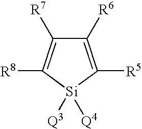
wherein Q3 and Q4 are each a saturated or unsaturated hydrocarbon group with 1 to 6 carbon atoms, an alkoxy group, an alkenyloxy group, an alkynyloxy group, a substituted or unsubstituted aryl group, or a substituted or unsubstituted heterocyclic group, or Q3 or Q4 are bonded to each other to form a saturated or unsaturated ring; and R5 to R8 are each a hydrogen atom, a halogen atom, a substituted or unsubstituted alkyl group with 1 to 6 carbon atoms, an alkoxy group, an aryloxy group, a perfluoroalkyl group, a perfluoroalkoxy group, an amino group, an alkylcarbonyl group, an arylcarbonyl group, an alkoxycarbonyl group, an aryloxycarbonyl group, an azo group, an alkylcarbonyloxy group, an arylcarbonyloxy group, an alkoxycarbonyloxy group, an aryloxycarbonyloxy group, a sulfinyl group, a sulfonyl group, a sulfanyl group, a silyl group, a carbamoyl group, an aryl group, a heterocyclic group, an alkenyl group, an alkynyl group, a nitro group, a formyl group, a nitroso group, a formyloxy group, an isocyano group, a cyanate group, an isocyanate group, a thiocyanate group, an isothiocyanate group, or a cyano group, or adjacent substituents of R5 to R8 are bonded to form a substituted or unsubstituted condensed ring structure: provided that in the case where R5 and R8 are each a phenyl group, Q3 and Q4 are neither an alkyl group nor a phenyl group; in the case where R5 and R8 are each a thienyl group, Q3, Q4, R6 and R7 do not form the structure where Q3 and Q4 are a monovalent hydrocarbon group and at the same time R6 and R7 are an alkyl group, an aryl group or an alkenyl group, or are aliphatic groups which form a ring by bonding to each other; in the case where R5 and R8 are a silyl group, R6, R7, Q3 and Q4 are each neither a monovalent hydrocarbon group with 1 to 6 carbon atoms nor a hydrogen atom; and in the case where a benzene ring is condensed at the positions of R5 and R6, Q3 and Q4 are neither an alkyl group nor a phenyl group.
Borane derivatives represented by the following formula, disclosed in JP-A1-2000-040586:
wherein R9 to R16 and Q8 are each a hydrogen atom, a saturated or unsaturated hydrocarbon group, an aromatic group, a heterocyclic group, a substituted amino group, a substituted boryl group, an alkoxy group or an aryloxy group; Q5, Q6 and Q7 are each a saturated or unsaturated hydrocarbon group, an aromatic group, a heterocyclic group, a substituted amino group, an alkoxy group or an aryloxy group; the substituents of Q7 and Q8 may be bonded to each other to form a condensed ring; r is an integer of 1 to 3, and Q7s may be different from each other when r is 2 or more; provided that excluded are the compounds where r is 1, Q5, Q6 and R10 are each a methyl group and R16 is a hydrogen atom or a substituted boryl group, and the compounds where r is 3 and Q7 is a methyl group.
Compounds represented by the following formula, disclosed in JP-A-10-088121:
wherein Q9 and Q10 are independently a ligand represented by the following formula (3); and L4 is a halogen atom, a substituted or unsubstituted alkyl group, a substituted or unsubstituted cycloalkyl group, a substituted or unsubstituted aryl group, a substituted or unsubstituted heterocyclic group, —OR17 wherein R17 is a hydrogen atom, a substituted or unsubstituted alkyl group, a substituted or unsubstituted cycloalkyl group, a substituted or unsubstituted aryl group or a substituted or unsubstituted heterocyclic group, or —O—Ga-Q11 (Q12) wherein Q11 and Q12 are the same legands as Q9 and Q10.
wherein rings A4 and A5 are each a 6-membered aryl ring structure which may have a substituent, and are condensed to each other. - The metal complexes have the strong nature of an n-type semiconductor and large ability of injecting electrons. Further the energy generated at the time of forming a complex is small so that a metal is then strongly bonded to ligands in the complex formed and the fluorescent quantum efficiency becomes large as the emitting material.
- Specific examples of substituents of the rings A4 and A5 which form the ligands of the above formula include halogen atoms such as chlorine, bromine, iodine and fluorine; substituted or unsubstituted alkyl groups such as methyl, ethyl, propyl, butyl, sec-butyl, tert-butyl, pentyl, hexyl, heptyl, octyl, stearyl and trichloromethyl; substituted or unsubstituted aryl groups such as phenyl, naphthyl, 3-methylphenyl, 3-methoxyphenyl, 3-fluorophenyl, 3-trichloromethylphenyl, 3-trifluoromethylphenyl and 3-nitrophenyl; substituted or unsubstituted alkoxy groups such as methoxy, n-butoxy, tert-butoxy, trichloromethoxy, trifluoroethoxy, pentafluoropropoxy, 2,2,3,3-tetrafluoropropoxy, 1,1,1,3,3,3-hexafluoro-2-propoxy and 6-(perfluoroethyl)hexyloxy; substituted or unsubstituted aryloxy groups such as phenoxy, p-nitrophenoxy, p-tert-butylphenoxy, 3-fluorophenoxy, pentafluorophenyl and 3-trifluoromethylphenoxy; substituted or unsubstituted alkylthio groups such as methythio, ethylthio, tert-butylthio, hexylthio, octylthio and trifruoromethyltio; substituted or unsubstituted arylthio groups such as phenylthio, p-nitropheny-lthio, p-tert-butylphenylthio, 3-fluorophenylthio, pentafluorophenylthio and 3-trifluoromethylphenylthio; a cyano group; a nitro group, an amino group; mono or di-substituted amino groups such as methylamino, dimethylamino, ethylamino, diethylamino, dipropylamino, dibutylamino and diphenylamino; acylamino groups such as bis(acetoxymethyl)amino, bis(acetoxyethyl)amino, bis (acetoxypropyl)amino and bis (acetoxybutyl)amino; a hydroxy group; a siloxy group; an acyl group; carbamoyl groups such as methylcarbamoyl, dimethylcarbamoyl, ethylcarbamoyl, diethylcarbamoyl, propylcarbamoyl, butylcarbamoyl and phenylcarbamoyl; a carboxylic group; a sulfonic acid group; an imido group; cycloalkyl groups such as cyclopentyl and cyclohexyl; aryl groups such as phenyl, naphthyl, biphenyl, anthranyl, phenanthryl, fluorenyl and pyrenyl; and heterocyclic groups such as pyridinyl, pyrazinyl, pyrimidinyl, pryidazinyl, triazinyl, indolinyl, quinolinyl, acridinyl, pyrrolidinyl, dioxanyl, piperidinyl, morpholidinyl, piperazinyl, triathinyl, carbazolyl, furanyl, thiophenyl, oxazolyl, oxadiazolyl, benzooxazolyl, thiazolyl, thiadiazolyl, benzothiazolyl, triazolyl, imidazolyl, benzoimidazolyl and puranyl. Moreover the above-mentioned substituents may be bonded to each other to form a six-membered aryl or heterocyclic ring.
- (7) Hole-injecting Layer
- In the invention, an electron-injecting layer which is formed of an insulator or a semiconductor may be provided between a cathode and an electron-injecting layer or between a cathode and an emitting layer. By providing such an electron-injecting layer, current leakage can be effectively prevented to improve the injection of electrons.
- As the insulator, a single metal compound or a combination of metal compounds selected from alkali metal calcogenides, alkaline earth metal calcogenides, halides of alkali metals, halides of alkaline earth metals, aluminum oxide, aluminum nitride, titanium oxide, silicon dioxide, germanium oxide, silicon nitride, boron nitride, molybdenum oxide, ruthenium oxide and vanadium oxide can be preferably used. Among these metal compounds, the alkali metal calcogenides or alkaline earth metal calcogenides are preferred in view of the injection of electrons. Preferable alkali metal calcogenides include Li2O, LiO, Na2S, Na2Se and NaO. Preferable alkaline earth metal calcogenides include CaO, BaO, SrO, BeO, BaS and CaSe. Preferable halides of alkali metals include LiF, NaF, KF, LiCl, KCl and NaCl. Preferable halides of alkaline earth metals include fluorides such as CaF2, BaF2, SrF2, MgF2 and BeF2 and halides other than fluorides.
- Examples of the semiconductor for forming the electron-injecting layer include oxides, nitrides or oxynitrides containing at least one element selected from Ba, Ca, Sr, Yb, Al, Ga, In, Li, Na, Cd, Mg, Si, Ta, Sb and Zn, and combinations of two or more thereof.
- The electron-injecting layer is preferably microcrystalline or amorphous. Because a more uniform thin film can be formed to reduce pixel defects such as dark spots.
- Two or more electron-injecting layers may be stacked.
- (8) Reducing Dopant
- A reducing dopant can be contained in an electron transporting region or an interface region between a cathode and an organic layer. The reducing dopant is defined as a substance which can reduce electron-transporting compounds. Various substances having reducibility can be used. The following can be preferably used: alkali metals, alkaline earth metals, rare earth metals, oxides of alkali metals, halides of alkali metals, oxides of alkaline earth metals, halides of alkaline earth metals, oxides of rare earth metals, halides of rare earth metals, organic complexes of alkali metals, organic complexes of alkaline earth metals and organic complexes of rare earth metals.
- Preferable examples of the reducing dopant are alkali metals such as Na (work function: 2.36 eV), K (work function: 2.28 eV), Rb (work function: 2.16 eV) and Cs (work function: 1.95 eV) or alkaline earth metals such as Ca (work function: 2.9 eV), Sr (work function: 2.0 to 2.5 eV) and Ba (work function: 2.52 eV). Among these, the reducing dopant is preferably K, Rb or Cs, more preferably Rb or Cs, and even more preferably Cs. Combinations of two or more of these alkali metals are preferable. Combinations with Cs, for example, Cs and Na, Cs and K, Cs and Rb or Cs, Na and K are particularly preferable.
- (9) Cathode
- For the cathode, the following may be preferred: an electrode substance made of a metal, an alloy, an electroconductive compound, or a mixture thereof which has a small work function (4 eV or less). Specific examples of the electrode substance include sodium, sodium-potassium alloy, magnesium, lithium, magnesium/silver alloy, aluminum/aluminum oxide, aluminum/lithium alloy, indium, and rare earth metals.
- The cathode preferably contains a metal oxide.
- As the metal oxide, at least one metal oxide selected from LixTi2O4, LixV2O4, ErxNbO3, LaxTiO3, SrxVO3, CaxCrO3 and SrxCrO3 (X is 0.2 to 5) is exemplified. As the metal oxide, at least one metal oxide selected from AxMoO3 (A is K, Cs, Rb, Sr, Na, Li or Ca) (x is 0.2 to 5) and AxV2O5 (A is K, Cs, Rb, Sr, Na, Li or Ca) (x is 0.2 to 5) is exemplified.
- The cathode more preferably contains at least one metal selected from alkali metals and alkaline earth metals to improve electron injecting ability. Preferred metals include Na, K, Cs and Mg.
- The cathode can be formed by making the electrode substances into a thin film by vapor deposition, sputtering or some other method.
- In the case where luminescence from the emitting layer is outcoupled through the cathode, the transmittance of the cathode to luminescence is preferably 10% or more, more preferably 30% or more, even more preferably 50% or more.
- The sheet resistance of the cathode is preferably 1000 Ω/□ or less, more preferably 800 Ω/□ and even more preferably 600 Ω/□.
- The film thickness of the cathode is not limited, and is preferably 10 nm to 1 μm, more preferably from 50 to 200 nm.
- In the case where luminescence is outcoupled through the anode, the cathode is preferably a reflecting electrode.
- (10) Insulative Layer
- In the organic EL device, pixel defects due to leakage or a short circuit are easily generated since an electric field is applied to the super thin film. In order to prevent this, it is preferred to insert an insulator thin layer between the cathode and organic layers.
- Examples of the material used in the insulative layer include aluminum oxide, lithium fluoride, lithium oxide, cesium fluoride, cesium oxide, magnesium oxide, magnesium fluoride, calcium oxide, calcium fluoride, aluminum nitride, titanium oxide, silicon oxide, germanium oxide, silicon nitride, boron nitride, molybdenum oxide, ruthenium oxide, and vanadium oxide.
- In the invention, a mixture or multilayer thereof may be used.
- (11) Protecting Layer
- A protecting layer is formed so as to protect an organic layer when forming an anode.
- In general, metals including Ag and Au, and alloys thereof, which have a greater transparency, are used. In addition to these, a semiconductor or an insulator may be used to achieve the above object.
- Specifically, the materials exemplified for the insulator layer and the materials exemplified for the metal oxides are preferably used. Examples of the semiconductor include CdSe, CdS, ZnS and ZnSe.
- For the protecting layer, these materials may be used individually or in a mixture thereof. These materials may also be used in combination with materials for other applications.
- Usually, the film thickness of the protecting layer is preferably in the range of several nanometers to several tens nanometers, particularly preferably of 1 nm to 10 nm to enhance its transparency.
- (12) Metal Layer
- A metal layer can be provided between a conductive film forming an anode and a protecting film, a metal oxide layer and an anode, or an emitting layer and a metal oxide layer.
- The metal layer can be formed from an alloy containing at least one metal selected from Mg, Ag and Zr.
- The film thickness is not limited, but preferably from 0.1 nm to 10 μm, and more preferably from 1 nm to 15 nm.
- (13) Example of Fabricating Organic EL Device
- An example of producing the organic EL device of the first embodiment will be described below which has a structure wherein the following are successively formed on a substrate: cathode/electron-transporting layer/emitting layer/hole-injecting layer/protecting layer/anode.
- A thin film made of a cathode material is formed into a thickness of 1 μm or less, preferably 10 to 200 nm on a substrate by vapor deposition, sputtering or some other method, thereby forming a cathode. Next, an electron-transporting layer is formed on this cathode. The electron-transporting layer can be formed by vacuum deposition, spin coating, casting, LB technique, or some other method. Vacuum deposition is preferred since a homogenous film is easily obtained and pinholes are not easily generated. In the case where the electron-transporting layer is formed by vacuum deposition, conditions for the deposition vary depending on a compound to use (material for the electron-transporting layer), an intended crystal structure or recombining structure of the electron-transporting layer, and so on. In general, the conditions are appropriately selected from the following: deposition source temperatures of 50 to 450° C., vacuum degrees of 10−7 to 10−3 torr, vapor deposition rates of 0.01 to 50 nm/second, substrate temperatures of −50 to 300° C., and film thicknesses of 5 nm to 5 μm.
- Next, an emitting layer is disposed on the electron-transporting layer. The emitting layer can be formed by making a desired organic luminescent material into a thin film by vacuum deposition, sputtering, spin coating, casting or some other method. Vacuum deposition is preferred since a homogenous film is easily obtained and pinholes are not easily generated. In the case where the emitting layer is formed by vacuum deposition, conditions for the deposition, which vary depending on a compound to use, can be generally selected from conditions similar to those for the electron-transporting layer.
- Next, a hole-injecting layer is formed on this emitting layer. Like the electron-transporting layer and the emitting layer, the layer is preferably formed by vacuum deposition since a homogenous film need be obtained. Conditions for the deposition can be selected from conditions similar to those for the electron-transporting layer and the emitting layer.
- A protecting layer is formed in a thickness of several nm to several tens nm on this hole-injecting material. This protecting layer can be formed using various methods, specifically vacuum deposition, sputtering, electron beam deposition, etc. When the protecting layer is formed by vacuum deposition, the deposition conditions vary depending on a compound to use (material for the hole-injecting layer), an intended crystal structure or recombining structure of the protecting layer, and so on. In general, the conditions are appropriately selected from the following: deposition source temperatures of 500 to 1000° C., vacuum degrees of 10−7 to 10−3 torr, vapor deposition rates of 0.01 to 50 nm/second, substrate temperatures of −50 to 300° C., and film thicknesses of 1 nm to 20 nm.
- Lastly, an anode is stacked thereon to obtain an organic EL device.
- The anode is made of a metal, and vapor deposition or sputtering may be used. However, vacuum deposition is preferred in order to protect underlying organic layers from being damaged when the anode is formed.
- An example of the production of the organic EL device of the second embodiment will be described below which has a structure wherein the following are successively formed on a substrate: cathode/electron-transporting layer/emitting layer/hole-injecting layer/metal oxide layer/anode.
- The same steps from a cathode to a hole-injecting layer as in the above example of the production of the first embodiment are repeated.
- A metal oxide layer is formed in a thickness of several nm to several tens nm on the hole-injecting layer. This metal oxide layer can be formed using various methods, specifically vacuum deposition, sputtering, electron beam deposition, etc. Vacuum deposition is preferred due to less damage to the hole-injecting layer. When the metal oxide layer is formed by vacuum deposition, the deposition conditions vary depending on a compound to use, an intended crystal structure or recombining structure of the metal oxide layer, and so on. In general, the conditions are appropriately selected from the following: deposition source temperatures of 50 to 500° C., vacuum degrees of 10−7 to 10−3 torr, vapor deposition rates of 0.01 to 50 nm/second, substrate temperatures of −50 to 300° C., and film thicknesses of 1 nm to 20 nm.
- An anode is formed on the metal oxide layer in the same way as in the above-mentioned production example.
- For the organic EL element production that has been described above, it is preferred that the formation from the cathode to the anode is continuously carried out, using only one vacuuming operation.
- The method for forming each of the layers in the organic EL device of the invention is not particularly limited. A known forming method such as vacuum deposition or spin coating can be used. An organic thin layer used in the organic EL device of the invention can be formed in known ways such as vacuum deposition, molecular beam deposition (MBE method), or application of a solution in which a material is dissolved in a solvent such as dipping, spin coating, casting, bar coating or roll coating.
- The film thickness of each of the organic layers in the organic EL device of the invention is not particularly limited. In general, defects such as pinholes are easily generated when the film thickness is too small. Conversely, a high applied voltage becomes necessary, leading to worse efficiency when the film thickness is too large. Usually, therefore, the film thickness is preferably in the range of several nanometers to one micrometer.
- A glass substrate, 25 mm×75 mm×1.1 mm thick, (manufactured by Geomatics Co.) was subjected to ultrasonic cleaning in isopropyl alcohol for 5 minutes, followed by UV ozone cleaning for 30 minutes.
- The cleaned glass substrate was mounted in a substrate holder in a vacuum deposition device. Metal Al was deposited in a thickness of 150 nm to form a metal cathode.
- Next, LiF was deposited in a thickness of 1 nm on the cathode as an electron-injecting layer.
- Next, Alq was deposited in a thickness of 20 nm. This film functioned as an electron-transporting layer.
- Next, H1 illustrated below was deposited to form a 40 nm thick film on this electron-transporting layer. At the same time, as a luminescent molecule, a dopant D1 illustrated below was co-deposited. The deposition ratio was H1:D1=40:2 (weight ratio). This film functioned as an emitting layer.
- An N,N,N′,N′-tetra(4-biphenyl)-diaminobiphenylene layer (TBDB layer hereinafter) was formed in a thickness of 20 nm on this emitting layer. This film functioned as a hole-transporting layer.
- Further, molybdenum trioxide and TBDB were co-deposited on this hole-transporting layer. The deposition rate ratio was such that the thickness ratio of molybdenum trioxide to TBDB was 3 nm to 60 nm. The thickness of the film was 60 nm. This film functioned as a hole-injecting layer.
- Next, molybdenum trioxide was heated using a resistant heating boat and a 5 nm thick film was formed on the hole-injecting layer. This film was a protecting layer.
- Lastly, IZO was deposited by sputtering at room temperature in a thickness of 150 nm on the protecting layer to form a transparent anode, thereby fabricating an organic EL device.
- The voltage required for applying a current density of 10 mA/cm2 to this organic EL device and half life thereof at an initial luminance of 1,000 nit are shown in Table 1.


- An organic EL device was fabricated in the same way as in Example 1 except that the protecting layer was not formed and the film thickness of the hole-injecting layer is 120 nm.
- The voltage required for applying a current density of 10 mA/cm2 to this organic EL device and half life thereof at an initial luminance of 1,000 nit are shown in Table 1.
- An organic EL device was fabricated in the same way as in Example 1 except that the metal oxide of the hole-injecting layer was not co-depositied.
- The voltage required for applying a current density of 10 mA/cm2 to this organic EL device and half life thereof at an initial luminance of 1,000 nit are shown in Table 1.
TABLE 1 Driving voltage Half life (@10 mA/cm2) (L0 = 1,000nit) Example 1 5.8 V 6200 h Example 2 6.1 V 5800 h Comparative 7.1 V 4300 h Example 1 - A glass substrate, 25 mm×75 mm×1.1 mm thick, having Ag (thickness: 20 nm) and ITO (thickness: 130 nm) electrodes (manufactured by Geomatics Co.) was subjected to ultrasonic cleaning in isopropyl alcohol for 5 minutes and then in distilled water having an electrical resistance of 20 MΩm for 5 minutes, and further ultrasonic cleaning in isopropyl alcohol for 5 minutes. The resultant substrate was removed and dried. Immediately thereafter, the substrate was subjected to UV ozone cleaning for 30 minutes with an UV ozone device manufactured by Opto Films Lab.
- The cleaned glass substrate with electrode was mounted in a substrate holder in a vacuum deposition device. The inside of the device was vacuumed to 1×10⁻⁵ Pa.
- Firstly, Alq and Li were deposited to form a 20 nm thick film at a deposition rate of 0.1 nm/sec and 0.01 nm/sec respectively on the surface on which the transparent electrode lines were formed, so as to cover the electrode.
- A host material (H1) was deposited at a deposition rate of 0.2 nm/sec to form a 40 nm thick film thereon. Then, a dopant (D1) was deposited as a luminescent molecule at a deposition rate of 0.01 nm/sec simultaneously. This layer functioned as an emitting layer.
- Furthermore, an N,N,N′,N′-tetra(4-biphenyl)-diaminobiphenylene (TBDB) layer having a thickness of 20 nm was formed at a deposition rate of 0.1 nm/sec. This film functioned as a hole-transporting layer.
- A N,N′-bis(N,N′-diphenyl-4-aminophenyl)-N,N-diphenyl-4,4′-diamino-1,1′-biphenyl (TPD 232) film was formed in a thickness of 60 nm at a deposition rate of 0.1 nm/sec on the TBDB layer. This TPD 232 film functioned as a hole-injecting layer.
- After the formation of the TPD 232 film, a MoO3 film was formed in a thickness of 10 nm at a deposition rate of 0.02 nm/sec on this TPD 232 film.
- Next, an ITO film was formed in a thickness of 100 nm at a deposition rate of 0.4 nm/s.
- Then, the initial performance of this organic EL device was measured at a current density of 1 mA/cm2, using the light-reflecting electrode as a cathode. The results were a driving voltage of 4.5 V, 10 cd/A, and CIEx, y=(0.16, 0.26).
- For a current linkage, the current value was measured by applying voltage of 5 V in reverse bias. The current linkage was 2×10⁻⁹ A/cm2.
- The lifetime was measured at room temperature by driving with a constant direct current. At this time a current was adjusted to the current value at an initial luminance of 3000 nit and the current was continuously applied. A half-life is a period of time until the initial luminance was reduced by half. The lifetime was 2000 hr.
- The results are shown in Table 2.
- An organic EL device was fabricated in the same way as in Example 3 except that Au was used instead of MoO3 to form a film in a thickness of 5 nm at a deposition rate of 0.05 nm/sec.
- The initial performance was a driving voltage of 7 V, 6.0 cd/A, and CIEX, y=(0.16, 0.25). The current linkage was 1×10⁻⁶ A/cm2. The half-life was 1000 hr.
- An organic EL device was fabricated in the same way as in Example 3 except that after the deposition of MoO3, Mg and Ag were co-deposited to form a 1.5 nm thick film at a deposition rate of 1.5 nm/sec and 0.1 nm/sec respectively.
- The initial performance was a driving voltage of 5 V, 11 cd/A, and CIEx, y=(0.15, 0.26). The current linkage was 5×10⁻⁹ A/cm2. The half-life was 2000 hr.
- An organic EL device was fabricated in the same way as in Example 3 except that a glass substrate was used instead of the glass substrate having electrodes, metal Al was deposited to form a 100 nm thick film at a deposition rate of 0.8 nm/sec before the deposition of Alq and Li, and Cs and MoOx (x is 2 to 3) were co-deposited to form a cathode in a thickness of 1 nm at a deposition rate of 0.01 nm/sec and 0.1 nm/sec respectively.
- The initial performance was a driving voltage of 4.5 V, 11 cd/A, and CIEx, y=(0.16, 0.26). The current linkage was 3×10⁻⁹ A/cm2. The half-life was 2000 hr.
TABLE 2 Lifetime at initial luminance @1 mA/cm2 of 3000 nit Current Voltage L/J CIE Half life linkage (V) (cd/A) (x, y) (h) (A/cm2) Example 3 4.5 10 0.16, 0.26 2000 2 × 10⁻⁹ Comparative 7 6.0 0.16, 0.25 1000 1 × 10⁻⁶ example 2 Example 4 5 11 0.15, 0.26 2000 5 × 10⁻⁹ Example 5 4.5 11 0.16, 0.26 2000 3 × 10⁻⁹ - The organic EL device of the invention can be applied to personal and industrial displays, specifically, a cellular phone, PDA, automobile navigation system, monitor, TV, etc.
Claims (27)
1. An organic electroluminescent device comprising:
at least a cathode, an emitting layer, a hole-injecting layer and an anode on a substrate in this order;
the hole-injecting layer comprising a metal oxide.
2. The organic electroluminescent device according to claim 1 , wherein the hole-injecting layer has a thickness of 40 to 1000 nm.
3. The organic electroluminescent device according to claim 1 , wherein the metal oxide is an oxide of a metal of the groups 3 to 13 in the long form periodic table.
4. The organic electroluminescent device according to claim 1 , wherein the metal oxide is one, or two or more metal oxides selected from a molybdenum oxide, vanadium oxide, hafnium oxide, yttrium oxide, zinc oxide and aluminum oxide.
5. The organic electroluminescent device according to claim 1 , wherein the hole-injecting layer comprises 0.01 to 50 atm % of the metal oxide.
6. The organic electroluminescent device according to claim 1 , wherein a protecting layer is provided between the hole-injecting layer and the anode.
7. The organic electroluminescent device according to claim 6 , wherein the protecting layer comprises a metal.
8. The organic electroluminescent device according to claim 7 , wherein the protecting layer comprises Ag, Au or an alloy thereof.
9. The organic electroluminescent device according to claim 6 , wherein the protecting layer comprises a semiconductor.
10. The organic electroluminescent device according to claim 6 , wherein the protecting layer comprises an insulator.
11. The organic electroluminescent device according to claim 1 , wherein an insulative layer is provided between the cathode and the emitting layer.
12. The organic electroluminescent device according to claim 1 , wherein an electron-transporting layer is provided between the cathode and the emitting layer, or the insulative layer and the emitting layer.
13. An organic electroluminescent device comprising:
at least a cathode, an emitting layer, a metal oxide layer and an anode on a substrate in this order.
14. The organic electroluminescent device according to claim 13 , wherein the metal oxide layer comprises at least one metal oxide selected from a molybdenum oxide, vanadium oxide, rhenium oxide, ruthenium oxide, tungsten oxide, zinc oxide, titanium oxide and copper oxide.
15. The organic electroluminescent device according to claim 13 , wherein the anode comprises a conductive film and a protecting film in this order from the substrate.
16. The organic electroluminescent device according to claim 15 , wherein the protecting film comprises an oxide, a nitride or an oxynitride of at least one element selected from Si, Ge, Mg, Ta, Ti, Zn, Sn, In, Pb and Bi.
17. The organic electroluminescent device according to claim 15 , wherein the protecting film comprises an oxide, a nitride or an oxynitride of at least one element selected from the group consisting of Mo, V, Cr, W, Ni, Co, Mn, Ir, Pt, Pd, Ce, Pr, Nd, Sm, Eu, Gd, Tb, Dy, Er and Yb.
18. The organic electroluminescent device according to claim 15 , wherein the protecting film transmits light.
19. The organic electroluminescent device according to claim 15 , wherein a metal layer is provided between the conductive film and the protecting film.
20. The organic electroluminescent device according to claim 15 , wherein a metal layer is provided between the metal oxide layer and the anode, or the emitting layer and the metal oxide layer.
21. The organic electroluminescent device according to claim 19 , wherein the metal layer comprises an alloy containing at least one metal selected from Mg, Ag and Zr.
22. The organic electroluminescent device according to claim 13 , wherein the cathode comprises at least one metal selected from alkali metals and alkaline earth metal, and a metal oxide.
23. The organic electroluminescent device according to claim 22 , wherein the metal oxide contained in the cathode is at least one metal oxide selected from LixTi2O4, LixV2O4, ErxNbO3, LaxTiO3, SrxVO3, CaxCrO3 and SrxCrO 3 (X is 0.2 to 5).
24. The organic electroluminescent device according to claim 22 , wherein the metal oxide contained in the cathode is at least one metal oxide selected from AxMoO3 (A is K, Cs, Rb, Sr, Na, Li or Ca) (x is 0.2 to 5) and AxV2O5 (A is K, Cs, Rb, Sr, Na, Li or Ca) (x is 0.2 to 5).
25. The organic electroluminescent device according to claim 1 , wherein the anode is a transparent electrode and the cathode is a reflecting electrode.
26. A display comprising the organic electroluminescent device according to claim 1 .
27. The organic electroluminescent device according to claim 11 , wherein an electron-transporting layer is provided between the insulative layer and the emitting layer.
Applications Claiming Priority (5)
| Application Number | Priority Date | Filing Date | Title |
|---|---|---|---|
| JP2004-062772 | 2004-03-05 | ||
| JP2004062772A JP2005251639A (en) | 2004-03-05 | 2004-03-05 | Organic electroluminescent element and organic el display apparatus |
| JP2004070075A JP2005259550A (en) | 2004-03-12 | 2004-03-12 | Organic el device and display |
| JP2004-070075 | 2004-03-12 | ||
| PCT/JP2005/000862 WO2005086538A1 (en) | 2004-03-05 | 2005-01-24 | Organic electroluminescent device and organic electroluminescent display |
Publications (1)
| Publication Number | Publication Date |
|---|---|
| US20070170843A1 true US20070170843A1 (en) | 2007-07-26 |
Family
ID=34921708
Family Applications (1)
| Application Number | Title | Priority Date | Filing Date |
|---|---|---|---|
| US10/590,076 Abandoned US20070170843A1 (en) | 2004-03-05 | 2005-01-24 | Organic electroluminescent device and organic electroluminescent display |
Country Status (5)
| Country | Link |
|---|---|
| US (1) | US20070170843A1 (en) |
| EP (1) | EP1722602A1 (en) |
| KR (1) | KR20060135801A (en) |
| TW (1) | TW200531589A (en) |
| WO (1) | WO2005086538A1 (en) |
Cited By (31)
| Publication number | Priority date | Publication date | Assignee | Title |
|---|---|---|---|---|
| US20050212003A1 (en) * | 2004-03-24 | 2005-09-29 | Hitachi Displays, Ltd. | Organic light-emitting display device |
| US20060284189A1 (en) * | 2005-06-08 | 2006-12-21 | Junichiro Sakata | Light-emitting element, light-emitting device, and electronic device |
| US20060292394A1 (en) * | 2005-06-22 | 2006-12-28 | Semiconductor Energy Laboratory Co., Ltd. | Light emitting device and electronic appliance using the same |
| US20070046179A1 (en) * | 2005-08-26 | 2007-03-01 | Chan-Ching Chang | Organic electro-luminescent device |
| US20070244320A1 (en) * | 2006-03-21 | 2007-10-18 | Semiconductor Energy Laboratory Co., Ltd. | Organometallic complex and light emitting element, light emitting device, and electronic device using the organometallic complex |
| US20080203385A1 (en) * | 2003-10-03 | 2008-08-28 | Semiconductor Energy Laboratory Co., Ltd. | Light emitting element and manufacturing method thereof, and light emitting device using the light emitting element |
| US20080238832A1 (en) * | 2007-04-02 | 2008-10-02 | Fuji Xerox Co., Ltd | Organic electroluminescent device and display device |
| US20080305361A1 (en) * | 2007-06-05 | 2008-12-11 | Semiconductor Energy Laboratory Co., Ltd. | Organometallic Complex, and Light-Emitting Material, Light-Emitting Element, Light-Emitting Device and Electronic Device |
| US20090015143A1 (en) * | 2005-03-17 | 2009-01-15 | Semiconductor Energy Laboratory Co., Ltd. | Organometallic Complex, and Light-Emitting Element, Light-Emitting Device and Electronic- Device Using the Organometallic Complex |
| US20090085470A1 (en) * | 2007-09-28 | 2009-04-02 | Won-Jun Song | Organic light emitting device |
| US20090128012A1 (en) * | 2007-11-15 | 2009-05-21 | Won-Jun Song | Organic light emitting device |
| US20090160319A1 (en) * | 2007-12-24 | 2009-06-25 | Samsung Sdi Co., Ltd. | Organic light emitting device |
| US20090167159A1 (en) * | 2007-12-28 | 2009-07-02 | Samsung Sdi Co., Ltd. | Organic light emitting device |
| US20090167156A1 (en) * | 2007-02-28 | 2009-07-02 | Idemitsu Kosan Co., Ltd. | Organic electroluminescence device |
| US20090167163A1 (en) * | 2006-03-15 | 2009-07-02 | Jung-Bum Kim | Fabrication Method For Organic Light Emitting Device And Organic Light Emitting Device Fabricated By The Same Method |
| US20090218934A1 (en) * | 2008-03-03 | 2009-09-03 | Samsung Sdi Co., Ltd. | Organic light-emitting device |
| US20090224656A1 (en) * | 2008-03-04 | 2009-09-10 | Samsung Sdi Co., Ltd. | Organic light-emitting device |
| US20090284136A1 (en) * | 2008-04-17 | 2009-11-19 | Fuji Electric Holdings Co., Ltd. | Organic light-emission device |
| US20100052523A1 (en) * | 2008-08-29 | 2010-03-04 | Samsung Mobile Display Co., Ltd. | Organic light emitting device and organic light emitting display apparatus |
| US20100145044A1 (en) * | 2005-12-05 | 2010-06-10 | Semiconductor Energy Laboratory Co., Ltd. | Organometallic Complex and Light-Emitting Element, Light-Emitting Device, and Electronic Device Using the Same |
| US20100187982A1 (en) * | 2008-12-19 | 2010-07-29 | E. I. Du Pont De Nemours And Company | Buffer bilayers for electronic devices |
| US20100207104A1 (en) * | 2007-04-23 | 2010-08-19 | Guenter Schmid | Electrical Organic Component and a Method for its Production |
| US20100237331A1 (en) * | 2008-05-16 | 2010-09-23 | E. I. Du Pont De Nemours And Company | Anode for an organic electronic device |
| US20110043103A1 (en) * | 2008-03-31 | 2011-02-24 | Sumitomo Chemical Company, Limited | Organic electroluminescence element and manufacturing method of the same |
| US20110057176A1 (en) * | 2008-01-18 | 2011-03-10 | Kang Min-Soo | Organic luminescent device and a production method for the same |
| US20110221061A1 (en) * | 2008-12-01 | 2011-09-15 | Shiva Prakash | Anode for an organic electronic device |
| US8274212B2 (en) | 2007-12-28 | 2012-09-25 | Samsung Mobile Display Co., Ltd. | Organic light emitting device including first hole injection layer and second hole injection layer |
| US8604466B2 (en) | 2009-03-24 | 2013-12-10 | Idemitsu Kosan Co., Ltd. | Organic electroluminescent element |
| US11038138B2 (en) | 2017-08-11 | 2021-06-15 | Lg Chem, Ltd. | Organic electroluminescent device and method for manufacturing the same |
| US11871655B2 (en) | 2016-05-10 | 2024-01-09 | Lg Chem, Ltd. | Organic electroluminescent device and manufacturing method therefor |
| US11910655B2 (en) | 2020-11-26 | 2024-02-20 | Japan Display Inc. | Display device |
Families Citing this family (72)
| Publication number | Priority date | Publication date | Assignee | Title |
|---|---|---|---|---|
| JP4925569B2 (en) * | 2004-07-08 | 2012-04-25 | ローム株式会社 | Organic electroluminescent device |
| EP1846963A4 (en) | 2005-02-08 | 2010-08-04 | Semiconductor Energy Lab | Light-emitting element, light-emitting device, and electronic appliance |
| KR101336111B1 (en) | 2005-02-28 | 2013-12-05 | 가부시키가이샤 한도오따이 에네루기 켄큐쇼 | Composite material, light emitting element, light emitting device and electronic appliance using the composite material |
| CN101263616B (en) | 2005-07-25 | 2011-05-11 | 株式会社半导体能源研究所 | Light emitting element, light emitting device, and electronic apparatus |
| CN101461073B (en) * | 2006-06-01 | 2013-01-02 | 株式会社半导体能源研究所 | Light-emitting element, light-emitting device and an electronic device |
| KR100835988B1 (en) * | 2006-12-06 | 2008-06-09 | 한국전자통신연구원 | Organic light emitting diode devices |
| JP4629715B2 (en) | 2006-12-06 | 2011-02-09 | 韓國電子通信研究院 | OLED element |
| KR100813854B1 (en) * | 2007-04-23 | 2008-03-17 | 삼성에스디아이 주식회사 | Organic light emitting device and manufacturing method thereof |
| JP5603254B2 (en) * | 2008-01-23 | 2014-10-08 | エルジー・ケム・リミテッド | Organic light emitting device and method of manufacturing the same |
| KR100922759B1 (en) * | 2008-02-26 | 2009-10-21 | 삼성모바일디스플레이주식회사 | Organic light emitting device |
| CN102549793B (en) * | 2009-09-30 | 2015-11-25 | 凸版印刷株式会社 | Organic electroluminescent device and use the display unit of this element and the manufacture method of organic electroluminescent device |
| KR101708847B1 (en) | 2010-04-08 | 2017-02-22 | 삼성디스플레이 주식회사 | Organic light emitting diode display and method for manufacturing the same |
| KR20210124523A (en) | 2011-11-17 | 2021-10-14 | 메르크 파텐트 게엠베하 | Spirodihydroacridine derivatives and the use thereof as materials for organic electroluminescent devices |
| CN104114672B (en) | 2012-02-14 | 2017-03-15 | 默克专利有限公司 | Two fluorene compound of spiral shell for organic electroluminescence device |
| EP4369378A3 (en) | 2012-03-15 | 2024-08-14 | Merck Patent GmbH | Electronic devices |
| DE102012011335A1 (en) | 2012-06-06 | 2013-12-12 | Merck Patent Gmbh | Connections for Organic Electronic Devices |
| KR102184852B1 (en) | 2012-09-18 | 2020-12-01 | 메르크 파텐트 게엠베하 | Materials for electronic devices |
| US9831441B2 (en) | 2012-10-31 | 2017-11-28 | Merck Patent Gmbh | Electronic device |
| JP6306033B2 (en) | 2012-11-12 | 2018-04-04 | メルク パテント ゲーエムベーハー | Materials for electronic devices |
| CN104884572B (en) | 2013-01-03 | 2017-09-19 | 默克专利有限公司 | material for electronic device |
| CN104009184A (en) * | 2013-02-26 | 2014-08-27 | 海洋王照明科技股份有限公司 | Organic electroluminescent device and preparation method thereof |
| EP3044286B1 (en) | 2013-09-11 | 2018-01-31 | Merck Patent GmbH | Organic electroluminescent device |
| KR102326623B1 (en) | 2014-03-18 | 2021-11-16 | 메르크 파텐트 게엠베하 | Organic electroluminescent device |
| US10683453B2 (en) | 2014-12-12 | 2020-06-16 | Merck Patent Gmbh | Organic compounds with soluble groups |
| US20180219156A1 (en) | 2015-07-22 | 2018-08-02 | Merck Patent Gmbh | Materials for organic electroluminescent devices |
| WO2017016632A1 (en) | 2015-07-29 | 2017-02-02 | Merck Patent Gmbh | Materials for organic electroluminescent devices |
| US10696664B2 (en) | 2015-08-14 | 2020-06-30 | Merck Patent Gmbh | Phenoxazine derivatives for organic electroluminescent devices |
| KR20180111905A (en) | 2016-02-05 | 2018-10-11 | 메르크 파텐트 게엠베하 | Materials for electronic devices |
| WO2017207596A1 (en) | 2016-06-03 | 2017-12-07 | Merck Patent Gmbh | Materials for organic electroluminescent devices |
| KR102126603B1 (en) * | 2016-07-14 | 2020-07-08 | 주식회사 엘지화학 | Organic light emitting diode and manufacturing method of the same |
| TWI764942B (en) | 2016-10-10 | 2022-05-21 | 德商麥克專利有限公司 | Electronic device |
| DE102017008794A1 (en) | 2016-10-17 | 2018-04-19 | Merck Patent Gmbh | Materials for use in electronic devices |
| TWI745467B (en) | 2016-11-02 | 2021-11-11 | 德商麥克專利有限公司 | Materials for electronic devices |
| CN110088112A (en) | 2016-11-08 | 2019-08-02 | 默克专利有限公司 | Compound for electronic device |
| WO2018095888A1 (en) | 2016-11-25 | 2018-05-31 | Merck Patent Gmbh | Bisbenzofuran-fused 2,8-diaminoindeno[1,2-b]fluorene derivatives and related compounds as materials for organic electroluminescent devices (oled) |
| CN109963856A (en) | 2016-11-25 | 2019-07-02 | 默克专利有限公司 | Indeno [1,2-B] fluorene derivative and related compound condensed as double benzofurans of the material for organic electroluminescence device (OLED) |
| KR102683465B1 (en) | 2017-02-02 | 2024-07-09 | 메르크 파텐트 게엠베하 | Materials for Electronic Devices |
| JP7118990B2 (en) | 2017-03-02 | 2022-08-16 | メルク パテント ゲーエムベーハー | Materials for electronic devices |
| CN110753685A (en) | 2017-06-23 | 2020-02-04 | 默克专利有限公司 | Material for organic electroluminescent device |
| JP7317725B2 (en) | 2017-06-28 | 2023-07-31 | メルク パテント ゲーエムベーハー | Materials for electronic devices |
| KR20200033932A (en) | 2017-07-28 | 2020-03-30 | 메르크 파텐트 게엠베하 | Spirobifluorene derivatives for use in electronic devices |
| CN111051294B (en) | 2017-09-08 | 2024-04-19 | 默克专利有限公司 | Material for electronic devices |
| CN108675975A (en) | 2017-10-17 | 2018-10-19 | 默克专利有限公司 | Material for organic electroluminescence device |
| KR20200090817A (en) | 2017-11-23 | 2020-07-29 | 메르크 파텐트 게엠베하 | Materials for electronic devices |
| TWI820057B (en) | 2017-11-24 | 2023-11-01 | 德商麥克專利有限公司 | Materials for organic electroluminescent devices |
| TWI838352B (en) | 2017-11-24 | 2024-04-11 | 德商麥克專利有限公司 | Materials for organic electroluminescent devices |
| US20200308129A1 (en) | 2017-12-15 | 2020-10-01 | Merck Patent Gmbh | Substituted aromatic amines for use in organic electroluminescent devices |
| WO2019121483A1 (en) | 2017-12-20 | 2019-06-27 | Merck Patent Gmbh | Heteroaromatic compounds |
| TW201938761A (en) | 2018-03-06 | 2019-10-01 | 德商麥克專利有限公司 | Materials for organic electroluminescent devices |
| TWI802656B (en) | 2018-03-06 | 2023-05-21 | 德商麥克專利有限公司 | Materials for organic electroluminescent devices |
| WO2019175149A1 (en) | 2018-03-16 | 2019-09-19 | Merck Patent Gmbh | Materials for organic electroluminescent devices |
| CN108878683B (en) * | 2018-06-29 | 2019-09-06 | 云南大学 | A kind of metal oxide stack field-effect electrode |
| TWI837167B (en) | 2018-08-28 | 2024-04-01 | 德商麥克專利有限公司 | Materials for organic electroluminescent devices |
| CN112585242A (en) | 2018-08-28 | 2021-03-30 | 默克专利有限公司 | Material for organic electroluminescent device |
| TWI823993B (en) | 2018-08-28 | 2023-12-01 | 德商麥克專利有限公司 | Materials for organic electroluminescent devices |
| US20220048836A1 (en) | 2018-09-12 | 2022-02-17 | Merck Patent Gmbh | Materials for organic electroluminescent devices |
| KR20210088597A (en) | 2018-10-31 | 2021-07-14 | 메르크 파텐트 게엠베하 | Materials for organic electroluminescent devices |
| TW202136181A (en) | 2019-12-04 | 2021-10-01 | 德商麥克專利有限公司 | Materials for organic electroluminescent devices |
| KR20230043106A (en) | 2020-07-22 | 2023-03-30 | 메르크 파텐트 게엠베하 | Materials for organic electroluminescent devices |
| WO2023052272A1 (en) | 2021-09-28 | 2023-04-06 | Merck Patent Gmbh | Materials for electronic devices |
| KR20240075888A (en) | 2021-09-28 | 2024-05-29 | 메르크 파텐트 게엠베하 | Materials for Electronic Devices |
| WO2023052313A1 (en) | 2021-09-28 | 2023-04-06 | Merck Patent Gmbh | Materials for electronic devices |
| WO2023052275A1 (en) | 2021-09-28 | 2023-04-06 | Merck Patent Gmbh | Materials for electronic devices |
| WO2023094412A1 (en) | 2021-11-25 | 2023-06-01 | Merck Patent Gmbh | Materials for electronic devices |
| WO2023117837A1 (en) | 2021-12-21 | 2023-06-29 | Merck Patent Gmbh | Process for preparing deuterated organic compounds |
| CN118355092A (en) | 2021-12-21 | 2024-07-16 | 默克专利有限公司 | Electronic device |
| WO2023117835A1 (en) | 2021-12-21 | 2023-06-29 | Merck Patent Gmbh | Electronic devices |
| KR20240150795A (en) | 2022-02-14 | 2024-10-16 | 메르크 파텐트 게엠베하 | Materials for electronic devices |
| WO2023222559A1 (en) | 2022-05-18 | 2023-11-23 | Merck Patent Gmbh | Process for preparing deuterated organic compounds |
| WO2024013004A1 (en) | 2022-07-11 | 2024-01-18 | Merck Patent Gmbh | Materials for electronic devices |
| WO2024170605A1 (en) | 2023-02-17 | 2024-08-22 | Merck Patent Gmbh | Materials for organic electroluminescent devices |
| WO2024218109A1 (en) | 2023-04-20 | 2024-10-24 | Merck Patent Gmbh | Materials for electronic devices |
Citations (5)
| Publication number | Priority date | Publication date | Assignee | Title |
|---|---|---|---|---|
| US6259203B1 (en) * | 1997-07-31 | 2001-07-10 | Idemitsu Kosan Co., Ltd. | Organic electroluminescent device |
| US6416888B1 (en) * | 1999-02-15 | 2002-07-09 | Idemitsu Kosan Co., Ltd. | Organic electroluminescent device and method of manufacture thereof |
| US6437373B1 (en) * | 1998-05-08 | 2002-08-20 | Idemitsu Kosan Co., Ltd. | Organic electroluminescence layer with oligomer hole injection layer |
| US6489489B2 (en) * | 1996-10-08 | 2002-12-03 | Idemitsu Kosan Co., Ltd. | Organic electroluminescent device |
| US20030234609A1 (en) * | 2001-03-08 | 2003-12-25 | Xerox Corporation | Devices with multiple organic-metal mixed layers |
Family Cites Families (5)
| Publication number | Priority date | Publication date | Assignee | Title |
|---|---|---|---|---|
| JP3189480B2 (en) * | 1993-04-02 | 2001-07-16 | 富士電機株式会社 | Organic thin film light emitting device |
| JPH11251067A (en) * | 1998-03-02 | 1999-09-17 | Junji Kido | Organic electroluminescence element |
| JPH11307259A (en) * | 1998-04-23 | 1999-11-05 | Tdk Corp | Organic el element |
| JP4624653B2 (en) * | 2003-05-20 | 2011-02-02 | 出光興産株式会社 | Organic electroluminescence element and display device |
| JP2005026121A (en) * | 2003-07-03 | 2005-01-27 | Fujitsu Ltd | Organic el element and manufacturing method of the same as well as organic el display |
-
2005
- 2005-01-24 EP EP05704043A patent/EP1722602A1/en not_active Withdrawn
- 2005-01-24 KR KR1020067017948A patent/KR20060135801A/en not_active Application Discontinuation
- 2005-01-24 WO PCT/JP2005/000862 patent/WO2005086538A1/en not_active Application Discontinuation
- 2005-01-24 US US10/590,076 patent/US20070170843A1/en not_active Abandoned
- 2005-01-28 TW TW094102797A patent/TW200531589A/en unknown
Patent Citations (8)
| Publication number | Priority date | Publication date | Assignee | Title |
|---|---|---|---|---|
| US6489489B2 (en) * | 1996-10-08 | 2002-12-03 | Idemitsu Kosan Co., Ltd. | Organic electroluminescent device |
| US6259203B1 (en) * | 1997-07-31 | 2001-07-10 | Idemitsu Kosan Co., Ltd. | Organic electroluminescent device |
| US6504300B2 (en) * | 1997-07-31 | 2003-01-07 | Idemitsu Kosan Co., Ltd. | Organic electroluminescent device |
| US6437373B1 (en) * | 1998-05-08 | 2002-08-20 | Idemitsu Kosan Co., Ltd. | Organic electroluminescence layer with oligomer hole injection layer |
| US6762438B2 (en) * | 1998-05-08 | 2004-07-13 | Idemitsu Kosan Co., Ltd. | Organic electroluminescent layer with oligomer hole injection layer |
| US6416888B1 (en) * | 1999-02-15 | 2002-07-09 | Idemitsu Kosan Co., Ltd. | Organic electroluminescent device and method of manufacture thereof |
| US6635365B2 (en) * | 1999-02-15 | 2003-10-21 | Idemitsu Kosan Co., Ltd. | Organic electroluminescent device and method of manufacture thereof |
| US20030234609A1 (en) * | 2001-03-08 | 2003-12-25 | Xerox Corporation | Devices with multiple organic-metal mixed layers |
Cited By (57)
| Publication number | Priority date | Publication date | Assignee | Title |
|---|---|---|---|---|
| US8994007B2 (en) | 2003-10-03 | 2015-03-31 | Semiconductor Energy Laboratory Co., Ltd. | Light emitting element and manufacturing method thereof, and light emitting device using the light emitting element |
| US20080203385A1 (en) * | 2003-10-03 | 2008-08-28 | Semiconductor Energy Laboratory Co., Ltd. | Light emitting element and manufacturing method thereof, and light emitting device using the light emitting element |
| US7994496B2 (en) | 2003-10-03 | 2011-08-09 | Semiconductor Energy Laboratory Co., Ltd. | Light emitting element and manufacturing method thereof, and light emitting device using the light emitting element |
| US9461271B2 (en) | 2003-10-03 | 2016-10-04 | Semiconductor Energy Laboratory Co., Ltd. | Light emitting element and manufacturing method thereof, and light emitting device using the light emitting element |
| US7943963B2 (en) | 2004-03-24 | 2011-05-17 | Hitachi Displays, Ltd. | Organic light-emitting display device |
| US20050212003A1 (en) * | 2004-03-24 | 2005-09-29 | Hitachi Displays, Ltd. | Organic light-emitting display device |
| US8889266B2 (en) | 2005-03-17 | 2014-11-18 | Semiconductor Energy Laboratory Co., Ltd. | Organometallic complex, and light-emitting element, light-emitting device and electronic-device using the organometallic complex |
| US20090015143A1 (en) * | 2005-03-17 | 2009-01-15 | Semiconductor Energy Laboratory Co., Ltd. | Organometallic Complex, and Light-Emitting Element, Light-Emitting Device and Electronic- Device Using the Organometallic Complex |
| US20060284189A1 (en) * | 2005-06-08 | 2006-12-21 | Junichiro Sakata | Light-emitting element, light-emitting device, and electronic device |
| US8334057B2 (en) | 2005-06-08 | 2012-12-18 | Semiconductor Energy Laboratory Co., Ltd. | Light-emitting element, light-emitting device, and electronic device |
| US9263645B2 (en) | 2005-06-08 | 2016-02-16 | Semiconductor Energy Laboratory Co., Ltd. | Light-emitting element, light-emitting device, and electronic device |
| US8252434B2 (en) | 2005-06-22 | 2012-08-28 | Semiconductor Energy Laboratory Co., Ltd. | Light emitting device and electronic appliance using the same |
| US20060292394A1 (en) * | 2005-06-22 | 2006-12-28 | Semiconductor Energy Laboratory Co., Ltd. | Light emitting device and electronic appliance using the same |
| US8017252B2 (en) | 2005-06-22 | 2011-09-13 | Semiconductor Energy Laboratory Co., Ltd. | Light emitting device and electronic appliance using the same |
| US8815419B2 (en) | 2005-06-22 | 2014-08-26 | Semiconductor Energy Laboratory Co., Ltd. | Light emitting device and electronic appliance using the same |
| US8541114B2 (en) | 2005-06-22 | 2013-09-24 | Semiconductor Energy Laboratory Co., Ltd. | Light emitting device and electronic appliance using the same |
| US20070046179A1 (en) * | 2005-08-26 | 2007-03-01 | Chan-Ching Chang | Organic electro-luminescent device |
| US8247086B2 (en) | 2005-12-05 | 2012-08-21 | Semiconductor Energy Laboratory Co., Ltd. | Organometallic complex and light-emitting element, light-emitting device and electronic device using the same |
| US20100145044A1 (en) * | 2005-12-05 | 2010-06-10 | Semiconductor Energy Laboratory Co., Ltd. | Organometallic Complex and Light-Emitting Element, Light-Emitting Device, and Electronic Device Using the Same |
| US9187689B2 (en) | 2005-12-05 | 2015-11-17 | Semiconductor Energy Laboratory Co., Ltd. | Organometallic complex and light-emitting element, light-emitting device, and electronic device using the same |
| US20090167163A1 (en) * | 2006-03-15 | 2009-07-02 | Jung-Bum Kim | Fabrication Method For Organic Light Emitting Device And Organic Light Emitting Device Fabricated By The Same Method |
| US8969126B2 (en) | 2006-03-15 | 2015-03-03 | Lg Chem, Ltd. | Fabrication method for organic light emitting device and organic light emitting device fabricated by the same method |
| US9166189B2 (en) | 2006-03-15 | 2015-10-20 | Lg Chem, Ltd. | Fabrication method for organic light emitting device and organic light emitting device fabricated by the same method |
| US10103341B2 (en) | 2006-03-21 | 2018-10-16 | Semiconductor Energy Laboratory Co., Ltd. | Organometallic complex and light emitting element, light emitting device, and electronic device using the organometallic complex |
| US8999520B2 (en) | 2006-03-21 | 2015-04-07 | Semiconductor Energy Laboratory Co., Ltd. | Organometallic complex and light emitting element, light emitting device, and electronic device using the organometallic complex |
| US20070244320A1 (en) * | 2006-03-21 | 2007-10-18 | Semiconductor Energy Laboratory Co., Ltd. | Organometallic complex and light emitting element, light emitting device, and electronic device using the organometallic complex |
| US20090167156A1 (en) * | 2007-02-28 | 2009-07-02 | Idemitsu Kosan Co., Ltd. | Organic electroluminescence device |
| US20080238832A1 (en) * | 2007-04-02 | 2008-10-02 | Fuji Xerox Co., Ltd | Organic electroluminescent device and display device |
| US20100207104A1 (en) * | 2007-04-23 | 2010-08-19 | Guenter Schmid | Electrical Organic Component and a Method for its Production |
| US8829493B2 (en) | 2007-04-23 | 2014-09-09 | Osram Opto Semiconductors Gmbh | Electrical organic component polymeric rhenium compounds and a method for its production |
| US20080305361A1 (en) * | 2007-06-05 | 2008-12-11 | Semiconductor Energy Laboratory Co., Ltd. | Organometallic Complex, and Light-Emitting Material, Light-Emitting Element, Light-Emitting Device and Electronic Device |
| US20090085470A1 (en) * | 2007-09-28 | 2009-04-02 | Won-Jun Song | Organic light emitting device |
| US20090128012A1 (en) * | 2007-11-15 | 2009-05-21 | Won-Jun Song | Organic light emitting device |
| US7973467B2 (en) | 2007-11-15 | 2011-07-05 | Samsung Mobile Display Co., Ltd. | Organic light emitting device |
| US8557398B2 (en) | 2007-12-24 | 2013-10-15 | Samsung Display Co., Ltd. | Organic light emitting device |
| US20090160319A1 (en) * | 2007-12-24 | 2009-06-25 | Samsung Sdi Co., Ltd. | Organic light emitting device |
| US8274212B2 (en) | 2007-12-28 | 2012-09-25 | Samsung Mobile Display Co., Ltd. | Organic light emitting device including first hole injection layer and second hole injection layer |
| US20090167159A1 (en) * | 2007-12-28 | 2009-07-02 | Samsung Sdi Co., Ltd. | Organic light emitting device |
| CN104752616A (en) * | 2008-01-18 | 2015-07-01 | Lg化学株式会社 | Organic Luminescent Device And Production Method For The Same |
| US8686403B2 (en) | 2008-01-18 | 2014-04-01 | Lg Chem Ltd. | Organic luminescent device including a first electrode, two or more organic layers and a second electrode and a production method for the same |
| US20110057176A1 (en) * | 2008-01-18 | 2011-03-10 | Kang Min-Soo | Organic luminescent device and a production method for the same |
| US20090218934A1 (en) * | 2008-03-03 | 2009-09-03 | Samsung Sdi Co., Ltd. | Organic light-emitting device |
| US8142910B2 (en) | 2008-03-04 | 2012-03-27 | Samsung Mobile Display Co., Ltd. | Organic light-emitting device |
| US20090224656A1 (en) * | 2008-03-04 | 2009-09-10 | Samsung Sdi Co., Ltd. | Organic light-emitting device |
| US20110043103A1 (en) * | 2008-03-31 | 2011-02-24 | Sumitomo Chemical Company, Limited | Organic electroluminescence element and manufacturing method of the same |
| US20090284136A1 (en) * | 2008-04-17 | 2009-11-19 | Fuji Electric Holdings Co., Ltd. | Organic light-emission device |
| US8846441B2 (en) | 2008-05-16 | 2014-09-30 | E I Du Pont De Nemours And Company | Anode for an organic electronic device |
| US20100237331A1 (en) * | 2008-05-16 | 2010-09-23 | E. I. Du Pont De Nemours And Company | Anode for an organic electronic device |
| US8242487B2 (en) | 2008-05-16 | 2012-08-14 | E I Du Pont De Nemours And Company | Anode for an organic electronic device |
| US20100052523A1 (en) * | 2008-08-29 | 2010-03-04 | Samsung Mobile Display Co., Ltd. | Organic light emitting device and organic light emitting display apparatus |
| US20110221061A1 (en) * | 2008-12-01 | 2011-09-15 | Shiva Prakash | Anode for an organic electronic device |
| US8461758B2 (en) | 2008-12-19 | 2013-06-11 | E I Du Pont De Nemours And Company | Buffer bilayers for electronic devices |
| US20100187982A1 (en) * | 2008-12-19 | 2010-07-29 | E. I. Du Pont De Nemours And Company | Buffer bilayers for electronic devices |
| US8604466B2 (en) | 2009-03-24 | 2013-12-10 | Idemitsu Kosan Co., Ltd. | Organic electroluminescent element |
| US11871655B2 (en) | 2016-05-10 | 2024-01-09 | Lg Chem, Ltd. | Organic electroluminescent device and manufacturing method therefor |
| US11038138B2 (en) | 2017-08-11 | 2021-06-15 | Lg Chem, Ltd. | Organic electroluminescent device and method for manufacturing the same |
| US11910655B2 (en) | 2020-11-26 | 2024-02-20 | Japan Display Inc. | Display device |
Also Published As
| Publication number | Publication date |
|---|---|
| WO2005086538A1 (en) | 2005-09-15 |
| EP1722602A1 (en) | 2006-11-15 |
| KR20060135801A (en) | 2006-12-29 |
| TW200531589A (en) | 2005-09-16 |
Similar Documents
| Publication | Publication Date | Title |
|---|---|---|
| US8007924B2 (en) | Organic electroluminescent device and display using same | |
| US7663304B2 (en) | Organic electroluminescence element | |
| US7800299B2 (en) | Organic electroluminescent device and display using same | |
| US8106582B2 (en) | Organic electroluminescence display device | |
| US7528542B2 (en) | Organic electroluminescent device | |
| US20070170843A1 (en) | Organic electroluminescent device and organic electroluminescent display | |
| US7501189B2 (en) | White organic electroluminescent device | |
| JP5317386B2 (en) | Nitrogen-containing heterocyclic derivative and organic electroluminescence device using the same | |
| KR101308341B1 (en) | Material for organic electroluminescent device and organic electroluminescent device | |
| US20070042221A1 (en) | Organic electroluminescent device and display | |
| JP2008150310A (en) | Aromatic amine derivative and organic electroluminescent element using the same | |
| JPWO2007111263A1 (en) | Nitrogen-containing heterocyclic derivative and organic electroluminescence device using the same | |
| US7851073B2 (en) | Organic electroluminescence device and material for organic electroluminescence device | |
| JPWO2007111262A1 (en) | Nitrogen-containing heterocyclic derivative and organic electroluminescence device using the same | |
| KR20080103975A (en) | Naphthacene derivative and organic electroluminescent device using same | |
| US20070188084A1 (en) | Organic electroluminescence element and display | |
| US20070154733A1 (en) | Organic electroluminescence element and display | |
| JP2007063220A (en) | Nitrogen-containing heterocyclic derivative and organic electroluminescent device using the same | |
| JP5523486B2 (en) | Nitrogen-containing heterocyclic derivative and organic electroluminescence device using the same |
Legal Events
| Date | Code | Title | Description |
|---|---|---|---|
| AS | Assignment |
Owner name: IDEMITSU KOSAN CO., LTD., JAPAN Free format text: ASSIGNMENT OF ASSIGNORS INTEREST;ASSIGNORS:KAWAMURA, HISAYUKI;JUNKE, TADANORI;FUKUOKA, KENICHI;REEL/FRAME:020484/0095 Effective date: 20060629 |
|
| STCB | Information on status: application discontinuation |
Free format text: ABANDONED -- FAILURE TO RESPOND TO AN OFFICE ACTION |