US20060013437A1 - Method and apparatus for determining camera pose - Google Patents
Method and apparatus for determining camera pose Download PDFInfo
- Publication number
- US20060013437A1 US20060013437A1 US11/159,967 US15996705A US2006013437A1 US 20060013437 A1 US20060013437 A1 US 20060013437A1 US 15996705 A US15996705 A US 15996705A US 2006013437 A1 US2006013437 A1 US 2006013437A1
- Authority
- US
- United States
- Prior art keywords
- ray
- capturing device
- image capturing
- world point
- freedom
- Prior art date
- Legal status (The legal status is an assumption and is not a legal conclusion. Google has not performed a legal analysis and makes no representation as to the accuracy of the status listed.)
- Granted
Links
Images


Classifications
-
- G—PHYSICS
- G06—COMPUTING; CALCULATING OR COUNTING
- G06T—IMAGE DATA PROCESSING OR GENERATION, IN GENERAL
- G06T7/00—Image analysis
- G06T7/70—Determining position or orientation of objects or cameras
- G06T7/73—Determining position or orientation of objects or cameras using feature-based methods
-
- G—PHYSICS
- G06—COMPUTING; CALCULATING OR COUNTING
- G06T—IMAGE DATA PROCESSING OR GENERATION, IN GENERAL
- G06T2207/00—Indexing scheme for image analysis or image enhancement
- G06T2207/30—Subject of image; Context of image processing
- G06T2207/30244—Camera pose
Definitions
- a fundamental task in computer vision systems is determining the pose of the image capturing device (e.g., a video camera) given one or more images of known points in the world.
- the image capturing device e.g., a video camera
- An exemplary application of pose estimation is vehicle localization.
- vehicle localization By tracking environmental features from a vehicle-mounted camera, it is possible to estimate changes in vehicle position and to use this information for navigation, tracking or other purposes.
- current techniques for camera-based vehicle localization that are based on known pose estimation algorithms do not make optimal use of multiple cameras present on the vehicle, because existing methods for pose estimation assume a single-perspective camera model.
- ad hoc pose estimation methods are used. For example, pose may be estimated independently for each vehicle-mounted camera and the separate pose estimates subsequently combined. Thus, such methods do not generally make the best use of available information.
- one known method for determining the pose of a calibrated perspective camera implements the images of three known points in the world in order to constrain the possible poses of the camera to up to four pairs of solutions (where no more than one solution from each pair is valid). These solutions are typically generated in accordance with the known “three-point perspective pose problem”.
- this approach can be successfully applied in many circumstances, its utility, as it stands, is limited to particular camera geometries and viewpoints. Thus, this approach is less applicable to camera models having more generalized geometries (e.g., geometries that do not adhere to a central perspective model or correspond to a single viewpoint), which have become increasingly popular tools in computer vision systems.
- a method and apparatus for determining camera pose characterized by six degrees of freedom (e.g., for use in computer vision systems) is disclosed.
- an image captured by the camera is received, and at least two constraints on the potential pose are enforced in accordance with known relations of the image to the camera, such that the potential pose is constrained to two remaining degrees of freedom.
- At least one potential pose is then determined in accordance with the remaining two degrees of freedom.
- FIG. 1 is a flow diagram illustrating one embodiment of a method for determining camera pose, according to the present invention
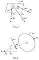
- FIG. 2 is a schematic diagram illustrating an exemplary image including images of three known world points
- FIG. 3 is a schematic diagram illustrating an exemplary pair of rays (and the effects that enforcement of the rays' constraints has on the first of the two remaining degrees of freedom;
- FIG. 4 is a schematic diagram further illustrating the effects that enforcement of the first and second rays' constraints has on the potential poses of a set of three rays including the pair of rays;
- FIG. 5 is a diagram illustrating the orthographic projection along the perpendicular axis of FIG. 4 ;
- FIG. 6 is a flow diagram illustrating one embodiment of a method for mapping known world points from their own coordinate system into a coordinate system of corresponding rays
- FIGS. 7A and 7B are graphs illustrating orthographic views of the transformation of the first and second rays and the known world points
- FIG. 8 is a schematic diagram illustrating one embodiment of a configuration of world points after being transformed onto their corresponding rays
- FIG. 9 is a graph illustrating an exemplary ruled quartic surface that may be traced out by the third ray due to the revolving motion associated with the second remaining degree of freedom;
- FIG. 10 is a flow diagram illustrating one embodiment of a method transforming between a coordinate system of world points and a coordinate system of corresponding rays, as discussed in further detail below;
- FIGS. 11A-11B are graphs illustrating the intersections of a circle and a ruled quartic surface, e.g., as obtained by enforcing the constraints of the first and second rays;
- FIG. 12 is a high level block diagram of the camera pose estimation method that is implemented using a general purpose computing device.
- the present invention discloses a method and apparatus for determining camera pose (e.g., for computer vision systems). Unlike conventional methods for determining pose, which rely of assumptions concerning the camera model or image capture geometry, the method and apparatus of the present invention function regardless of camera model or geometry, and thus may be implemented for determining the pose of substantially any kind of camera.
- a camera operating in conjunction with a curved mirror e.g., a catadioptric or a dioptric system
- a multi-camera rig e.g., a stereo camera head
- any compound camera comprising a plurality of individual sensing elements rigidly attached to each other are all potential configurations that may benefit from application of the present invention.
- one or more conventional cameras moving over time can be treated as a single generalized camera as long as the pose transformation relating the camera positions from one time to another is known.
- the only requirement imposed by the methods and devices to be described herein is that the spatial relationships among rays corresponding to image locations be known.
- the present invention deals with calibrated generalized cameras, including calibrated camera configurations as undistinguished special cases.
- FIG. 1 is a flow diagram illustrating one embodiment of a method 100 for determining camera pose, according to the present invention.
- the method 100 may be implemented to determine the pose of substantially any camera or image capturing device.
- the pose that is being determined is understood to have six degrees of freedom: three degrees for rotation and three degrees for translation.
- the method 100 is initialized in step 102 and proceeds to step 104 , where the method 100 receives an image (e.g., an individual frame of a sequence of scene imagery) that includes at least three known world points.
- the image is received from a generalized camera that samples a light field or plenoptic function in some arbitrary but known fashion.
- the image may be received from at least one of: a camera operating in conjunction with a curved mirror (e.g., a catadioptric or dioptric system), a multi-camera rig or a compound camera comprising a plurality of individual sensing elements rigidly attached to each other.
- the world points comprise any points in the real world that are captured in the received image and whose three-dimensional position in the real world is known.
- step 106 the method 100 identifies rays of points in the coordinate system of the image capturing device that project to three of the known world points.
- the image capturing device is calibrated such that these rays can be immediately derived.
- FIG. 2 is a schematic diagram illustrating an exemplary image 200 including images 202 1 - 202 3 (hereinafter collectively referred to as “images 202 ”) of three known world points 204 1 - 204 3 (hereinafter collectively referred to as “world points 204 ”). As illustrated, each image 202 of a known world point 204 and the corresponding world point 204 itself lies along a common ray 206 1 - 206 3 (hereinafter collectively referred to as “rays 206 ”). Generally, the pose of the image capturing device that captured the image 200 can be estimated by determining the rigid transformation of the three rays 206 such that all rays 206 meet their corresponding world points 204 . One embodiment of a method for determining this rigid transformation is described in greater detail below.
- the method 100 proceeds to step 108 and enforces the constraints given by two of the three rays (e.g., a first ray and a second ray).
- Enforcement of a single ray's constraints i.e., dictating that the ray should pass through a known world point
- the pose of the image capturing device is constrained from six degrees of freedom to two degrees of freedom. The poses of the entire set of three rays with respect to the world is thus constrained to a much narrower set of possibilities.
- the method 100 then proceeds to step 110 and determines the effects that the enforced constraints have on these remaining two degrees of freedom.
- One of these remaining two degrees of freedom can be considered in terms of a transformation of the known world point corresponding to the third ray.
- the second of the two remaining degrees of freedom can be considered in terms of possible positions of the third ray.
- step 112 the method 100 uses the knowledge of the remaining two degrees of freedom to determine possible transformations between the coordinate system of the world points and the coordinate system of the rays. These transformations represent potential solutions for the pose of the image capturing device.
- the method 100 then ends in step 114 .
- FIG. 3 is a schematic diagram illustrating an exemplary pair of rays (e.g., a first ray 300 1 and a second ray 300 2 , hereinafter collectively referred to as “rays 300 ”) and the effects that enforcement of the rays' constraints has on the first of the two remaining degrees of freedom (and hence on the potential poses of a set of three rays including the pair of rays 300 ).
- Three world points are known: a first world point 302 1 , a second world point 302 2 and a third world point 302 3 (hereinafter collectively referred to as “world points 302 ”).
- the first and second rays 300 meet first and second world points 302 1 , 302 3 , respectively.
- the first and second world points 302 1 , 302 3 define a unique axis 304 in space that passes through both the first world point and the second world point.
- the configuration of world points 302 may thus be rotated around the axis 304 without violating the constraints given by the first and second rays 300 (in effect, this illustrates the first of the remaining two degrees of freedom discussed above with respect to FIG. 1 ).
- Such a rotation enables the third world point 302 3 to trace a circle 306 in a plane that is substantially perpendicular to the axis 304 .
- a center point C of the circle 306 lies along the axis 304 .
- the world coordinate system may be considered as containing the first and second world points 302 1 , 302 3 and the circle 306 .
- the first remaining degree of freedom (discussed above) therefore enables the third world point 302 3 to trace out a circle relative to the image capturing device.
- FIG. 4 is a schematic diagram further illustrating the effects that enforcement of the first and second rays' constraints has on the potential poses of a set of three rays including the pair of rays 300 . Specifically, FIG. 4 illustrates the effect that enforcement of the constraints given by the first and second rays 300 has on the second of the remaining two degrees of freedom discussed above with respect to FIG. 1 .
- first and second rays 300 may be chosen as the first and second rays 300 , whose constraints are subsequently enforced.
- the first and second rays 300 will have a unique, common perpendicular direction and a unique perpendicular axis 400 in the common perpendicular direction that meets both rays 300 .
- the cylinder defined by the circles 400 also includes the first and second world points 302 1 , 302 2 , which lie on the circumference of respective circles 400 .
- the revolving motion of the perpendicular axis 400 affects all planes perpendicular to the perpendicular axis 400 in an equal manner.
- a cross section of the cylinder may be represented as illustrated in FIG. 5 .
- FIG. 5 is a diagram illustrating the orthographic projection along the perpendicular axis 400 of FIG. 4 (e.g., a cross-sectional view of the cylinder 500 ).
- the relative positions of the first and second rays 300 define an arc 504 therebetween.
- An angle subtending the arc 504 and defined by the first and second rays 300 (which meet at a point 502 on the cylinder 500 through which the perpendicular axis 400 described above passes) has a size ⁇ .
- ⁇ is useful to note that, as described by Book III of Euclid's Elements, all inscribed angles that subtend the same arc (e.g., arc 504 ) in a circle are equal.
- all angles subtending the arc 504 and inscribed in the circular cross section of the cylinder 500 will have a size of ⁇ .
- the effects of the revolving motion of the perpendicular axis 400 on the third ray may be determined using an algebraic representation.
- a family of transformations each transformation mapping the known world points 302 to one of the valid positions traced out by the revolving motion of the perpendicular axis 400 , is determined.
- the transformations map the known world points 302 into the coordinate system of the rays 300 .
- the world points that can map onto the third ray will lie on a ruled quartic surface that is traced by the third ray as the perpendicular axis 400 revolves.
- FIG. 6 is a flow diagram illustrating one embodiment of a method 600 for mapping known world points from their own coordinate system into a coordinate system of corresponding rays.
- the method 600 is initialized at step 602 and proceeds to step 604 , where the method 600 transforms the first and second rays 300 and the known world points 302 to starting positions that will simplify the subsequent analysis.
- FIGS. 7A and 7B are graphs illustrating orthographic views of the transformation of the first and second rays 300 and the known world points 302 .
- the first ray 300 1 coincides with the y-axis and the perpendicular axis 400 coincides with the z-axis.
- the origin 700 is where the first ray 300 1 meets the perpendicular axis 400 .
- the known world points 302 are then transformed such that the first and second world points 302 1 , 302 2 are disposed at particular positions.
- the first world point 302 1 coincides with the origin 700 .
- Rotation around the first world point 302 1 results in the second world point 302 2 lying on the line of intersection between the xz-plane and the z-plane of the second ray 300 2 .
- the location for the second world point 302 2 is chosen such that x ⁇ 0. This determines the coordinate system for the world points 302 up to a rotation around the axis defined by the first and second world points 302 1 , 302 2 . In one embodiment, this rotation is chosen arbitrarily.
- the method 600 proceeds to step 606 and transforms the first and second world points 302 onto their corresponding rays 300 .
- this transformation occurs in the xy-plane and applies to the world points 302 while keeping the rays 300 fixed.
- FIG. 8 is a schematic diagram illustrating one embodiment of a configuration of world points (e.g., world points 302 ) after being transformed onto their corresponding rays (e.g., rays 300 ), for example in accordance with step 606 of the method 600 .
- the illustrated configuration is one possible configuration that results from the translation and rotation in the xy-plane to place first and second world points 302 1 , 302 2 on first and second rays 300 1 , 300 2 , respectively.
- the revolving motion of the perpendicular axis (e.g., perpendicular axis 400 ) around the cylinder defined by circles 404 in FIG. 4 discussed above now maintains the established coincidence.
- the transformation must maintain the first world point 302 1 on the y-axis.
- the transformation maintains the second world point 302 2 on the second ray 300 2 .
- the one-dimensional family of valid transformations is parameterized by u and k under the constraint from EQN. 6.
- the method 600 proceeds to step 608 and determines the family of world points mapped onto the third ray by virtue of the revolving motion of the perpendicular axis (e.g., perpendicular axis 400 ) around the cylinder defined by circles 404 in FIG. 4 .
- the method 600 terminates in step 610 .
- FIG. 9 is a graph illustrating an exemplary ruled quartic surface 900 that may be traced out by the third ray due to the revolving motion associated with the second remaining degree of freedom.
- all sections of the ruled quartic surface 900 that are parallel to the xy-plane are limacons, and the vertices of the limacons form a twisted cubic, part of which is a curve of self-intersection for the ruled quartic surface 900 .
- a circle has up to eight intersections with a quartic curve, and these intersections correspond to a family of world points that lies along the third ray.
- FIGS. 11A-11B are graphs illustrating the intersections of a circle 1102 (e.g., derived as discussed in accordance with FIG. 3 ) and a ruled quartic surface 1104 (e.g., derived as discussed in accordance with FIG. 9 ), e.g., as obtained by enforcing the constraints of the first and second rays as discussed above.
- a plurality of intersections 1106 1 - 1106 8 (hereinafter collectively referred to as “intersections 1106 ”) exist between the circle 1102 and the ruled quartic surface 1104 .
- FIG. 11A shows four such intersections 1106 at the top surface 1108
- intersections 1106 at the bottom surface 1110 .
- the total of up to eight intersections 1106 between the circle 1102 and the ruled quartic surface 1104 represent up to eight possible solutions for transforming between a coordinate system of world points and a coordinate system of corresponding rays, as discussed in further detail below. Each of these transformations establishes a pose for the image capturing device with respect to the world points.
- FIG. 10 is a flow diagram illustrating one embodiment of a method 1000 transforming between a coordinate system of world points and a coordinate system of corresponding rays, as discussed in further detail below.
- the method 1000 is initialized at step 1002 and proceeds to step 1004 , where the method 1000 lines the three rays (e.g., rays 300 ) up in their canonical positions.
- the rays are represented by the points p 1 , p 2 and p 3 on the rays and by the unit direction vectors d 1 , d 2 and d 3 .
- d 1 is made parallel to the y-axis.
- the slope, s, of the second ray as defined by EQN. 1 will be: s ⁇ ( d 1 T d 2 )/( d 5 T d 2 ) (EQN. 20)
- the point at which the first ray meets the perpendicular axis is placed at the origin, such that the point is given as: p 4 ⁇ p 1 + ⁇ d 1 (EQN. 21) where ⁇ ( d 1 ⁇ sd 5 ) T ( p 2 ⁇ p 1 ) (EQN. 22)
- step 1006 the method 1000 lines up the world points (e.g., world points 302 ) up in their canonical positions.
- the world points are given as q 1 , q 2 and q 3 .
- the second ray now lies entirely in the z-plane, whose z-coordinate, e, is the z-coordinate of p 2 .
- (EQN. 25) is a unit vector in the direction from the origin toward the location where the second world point is to be positioned. Before the transformation, this direction is: d 7 ⁇ ( q 1 ⁇ q 2 )/
- the method 1000 computes the coefficients L and L′ of the two plane equations representing the third ray.
- the coefficient L and L′ are computed by finding two distinct normal vectors n and n′ that are perpendicular to d 3 .
- n is chosen as the vector of largest magnitude out of the two vector products d 3 ⁇ [1 0 0] and d 3 ⁇ [0 1 0] T .
- n′ is then chosen such that n′ ⁇ d 3 ⁇ n, and the plane vectors are: L ⁇ [n T ⁇ n T p 3 ] T (EQN. 31) and L′ ⁇ [n′ T ⁇ n T p 3 ] T (EQN. 32)
- step 1010 computes the coefficients of the octic polynomial whose roots correspond to the intersections of a circle and a ruled quartic surface.
- the octic polynomial, in z is derived by eliminating x and y from the quartic expression of EQN. 16.
- a 1 y K 3 +K 4 (EQN. 39)
- a 2 yK 5 +K 6 (EQN. 40)
- a 3 K 7 (EQN. 41)
- a′ 1 yK 8 +K 9 (EQN. 42)
- a′ 2 yK 10 +K 11 (EQN. 43)
- a′ 3 K 12 (EQN. 44)
- K 3 ⁇ I 2 EQN. 45
- K 4 ⁇ I 1 K 1 +sDI 2 (EQN. 46)
- K 6 ⁇ I 2 K 1 ⁇ DI 2 EQN.
- K 7 ⁇ zI 3 +I 4 (EQN. 49) K 8 ⁇ I′ 2 (EQN. 50) K 9 ⁇ I′ 1 K 1 +sDI′ 2 (EQN. 51) K 10 ⁇ I′ 1 (EQN. 52) K 11 ⁇ I′ 2 K 1 ⁇ DI′ 2 (EQN. 53) K 12 ⁇ zI 3 +I 4 (EQN. 54)
- K 19 K 20 y (EQN. 64) where K 19 ⁇ K 2 ( K 13 2 ⁇ K 15 2 ⁇ K 17 2 )+ K 14 2 ⁇ K 16 2 ⁇ K 18 2 (EQN. 65) K 20 ⁇ 2( K 15 K 16 +K 17 K 18 ⁇ K 13 K 14 ) (EQN. 66)
- K 21 0 (EQN. 67)
- K 21 K 19 2 ⁇ K 2 K 20 2 (EQN. 68) which is an octic polynomial in z whose roots correspond to the up to eight solutions.
- step 1010 the method 1000 proceeds to step 1012 and extracts the roots of the octic polynomial.
- the roots are extracted by eigen-decomposing a companion matrix.
- the octic polynomial is first normalized so that it may be written as: z 8 + ⁇ 7 z 7 + ⁇ 6 z 6 + . . . + ⁇ 0 (EQN. 69)
- the roots are then found as the eigenvalues of the 8 ⁇ 8 companion matrix: [ [ - ⁇ 7 - ⁇ 6 ... - ⁇ 0 1 ⁇ 1 ] ( EQN . ⁇ 70 )
- the roots of the octic polynomial may be found using Sturm sequences, e.g., as discussed by D. Nister in An Efficient Solution to the Five - Point Relative Pose Problem , IEEE Conference on Computer Vision and Pattern Recognition, Volume 2, pp. 195-202, 2003.
- the method 1000 proceeds to step 1014 and backsubstitutes with each root of the octic polynomial to get solutions for the transformation between the world point coordinate system and the ray coordinate system. In one embodiment, this is accomplished by computing, for each solution for z, x by EQN. 34 and y by EQN. 64. u and k can then be computed using EQNs. 14 and 15, respectively. The transformation defined in EQN. 7 is then uniquely determined and labeled as H 3 . For each solution, the transformation H 4 , which rotates the third world point q 3 around to the correct point on the circle, is also found.
- d 10 is defined such that: d 10 ⁇ ( d 6 ⁇ [x y z] T )/
- the transformation embodied in EQN. 74 is determined for each root of the octic polynomial such that up to eight transformations are obtained. These eight transformations represent potential solutions for transforming from the coordinate system of the world points to the coordinate system of the rays. Thus, the potential solutions may be treated as hypotheses for testing within a hypothesize-and-test architecture that determines the pose of the image capturing device.
- the method 1000 then terminates in step 1016 .
- FIG. 12 is a high level block diagram of the camera pose estimation method that is implemented using a general purpose computing device 1200 .
- a general purpose computing device 1200 comprises a processor 1202 , a memory 1204 , a camera pose estimation module 1205 and various input/output (I/O) devices 1206 such as a display, a keyboard, a mouse, a modem, and the like.
- I/O devices 1206 such as a display, a keyboard, a mouse, a modem, and the like.
- at least one I/O device is a storage device (e.g., a disk drive, an optical disk drive, a floppy disk drive).
- the camera pose estimation module 1205 can be implemented as a physical device or subsystem that is coupled to a processor through a communication channel.
- the camera pose estimation module 1205 can be represented by one or more software applications (or even a combination of software and hardware, e.g., using Application Specific Integrated Circuits (ASIC)), where the software is loaded from a storage medium (e.g., I/O devices 1206 ) and operated by the processor 1202 in the memory 1204 of the general purpose computing device 1200 .
- ASIC Application Specific Integrated Circuits
- the camera pose estimation module 1205 for determining the pose of a camera or other image capturing device described herein with reference to the preceding Figures can be stored on a computer readable medium or carrier (e.g., RAM, magnetic or optical drive or diskette, and the like).
- the present invention represents a significant advancement in the field of computer vision systems.
- a method and apparatus are provided that enable the pose of an image capturing device to be hypothesized based on a limited amount information known about the image capturing device and an image captured by the image capturing device.
- the method and apparatus function independently of the model or geometry of the image capturing device, and thus may be implemented for determining the pose of substantially any kind of image capturing device.
Landscapes
- Engineering & Computer Science (AREA)
- Computer Vision & Pattern Recognition (AREA)
- Physics & Mathematics (AREA)
- General Physics & Mathematics (AREA)
- Theoretical Computer Science (AREA)
- Image Analysis (AREA)
- Length Measuring Devices By Optical Means (AREA)
- Image Processing (AREA)
- Studio Devices (AREA)
Abstract
Description
- This application claims benefit of U.S. provisional patent application Ser. No. 60/581,868, filed Jun. 22, 2004, which is herein incorporated by reference in its entirety.
- The invention was made with Government support under grant number DMD19-01-2-0012 awarded by the United States Army. The Government has certain rights in this invention.
- The utility of computer vision systems in a variety of applications is widely recognized. A fundamental task in computer vision systems is determining the pose of the image capturing device (e.g., a video camera) given one or more images of known points in the world.
- An exemplary application of pose estimation is vehicle localization. By tracking environmental features from a vehicle-mounted camera, it is possible to estimate changes in vehicle position and to use this information for navigation, tracking or other purposes. However, current techniques for camera-based vehicle localization that are based on known pose estimation algorithms do not make optimal use of multiple cameras present on the vehicle, because existing methods for pose estimation assume a single-perspective camera model. As a result of this limitation, ad hoc pose estimation methods are used. For example, pose may be estimated independently for each vehicle-mounted camera and the separate pose estimates subsequently combined. Thus, such methods do not generally make the best use of available information.
- By way of further example, one known method for determining the pose of a calibrated perspective camera implements the images of three known points in the world in order to constrain the possible poses of the camera to up to four pairs of solutions (where no more than one solution from each pair is valid). These solutions are typically generated in accordance with the known “three-point perspective pose problem”. Though this approach can be successfully applied in many circumstances, its utility, as it stands, is limited to particular camera geometries and viewpoints. Thus, this approach is less applicable to camera models having more generalized geometries (e.g., geometries that do not adhere to a central perspective model or correspond to a single viewpoint), which have become increasingly popular tools in computer vision systems.
- Therefore, there is a need in the art for a method and apparatus for determining camera pose that is substantially model-independent.
- A method and apparatus for determining camera pose characterized by six degrees of freedom (e.g., for use in computer vision systems) is disclosed. In one embodiment an image captured by the camera is received, and at least two constraints on the potential pose are enforced in accordance with known relations of the image to the camera, such that the potential pose is constrained to two remaining degrees of freedom. At least one potential pose is then determined in accordance with the remaining two degrees of freedom.
- So that the manner in which the above recited features of the present invention can be understood in detail, a more particular description of the invention, briefly summarized above, may be had by reference to embodiments, some of which are illustrated in the appended drawings. It is to be noted, however, that the appended drawings illustrate only typical embodiments of this invention and are therefore not to be considered limiting of its scope, for the invention may admit to other equally effective embodiments.
-
FIG. 1 is a flow diagram illustrating one embodiment of a method for determining camera pose, according to the present invention; -
FIG. 2 is a schematic diagram illustrating an exemplary image including images of three known world points; -
FIG. 3 is a schematic diagram illustrating an exemplary pair of rays (and the effects that enforcement of the rays' constraints has on the first of the two remaining degrees of freedom; -
FIG. 4 is a schematic diagram further illustrating the effects that enforcement of the first and second rays' constraints has on the potential poses of a set of three rays including the pair of rays; -
FIG. 5 is a diagram illustrating the orthographic projection along the perpendicular axis ofFIG. 4 ; -
FIG. 6 is a flow diagram illustrating one embodiment of a method for mapping known world points from their own coordinate system into a coordinate system of corresponding rays; -
FIGS. 7A and 7B are graphs illustrating orthographic views of the transformation of the first and second rays and the known world points; -
FIG. 8 is a schematic diagram illustrating one embodiment of a configuration of world points after being transformed onto their corresponding rays; -
FIG. 9 is a graph illustrating an exemplary ruled quartic surface that may be traced out by the third ray due to the revolving motion associated with the second remaining degree of freedom; -
FIG. 10 is a flow diagram illustrating one embodiment of a method transforming between a coordinate system of world points and a coordinate system of corresponding rays, as discussed in further detail below; -
FIGS. 11A-11B are graphs illustrating the intersections of a circle and a ruled quartic surface, e.g., as obtained by enforcing the constraints of the first and second rays; and -
FIG. 12 is a high level block diagram of the camera pose estimation method that is implemented using a general purpose computing device. - The present invention discloses a method and apparatus for determining camera pose (e.g., for computer vision systems). Unlike conventional methods for determining pose, which rely of assumptions concerning the camera model or image capture geometry, the method and apparatus of the present invention function regardless of camera model or geometry, and thus may be implemented for determining the pose of substantially any kind of camera. For example, a camera operating in conjunction with a curved mirror (e.g., a catadioptric or a dioptric system), a multi-camera rig (e.g., a stereo camera head), or any compound camera comprising a plurality of individual sensing elements rigidly attached to each other are all potential configurations that may benefit from application of the present invention. Additionally, one or more conventional cameras moving over time can be treated as a single generalized camera as long as the pose transformation relating the camera positions from one time to another is known. In each case, the only requirement imposed by the methods and devices to be described herein is that the spatial relationships among rays corresponding to image locations be known. In other words, the present invention deals with calibrated generalized cameras, including calibrated camera configurations as undistinguished special cases.
-
FIG. 1 is a flow diagram illustrating one embodiment of amethod 100 for determining camera pose, according to the present invention. Themethod 100 may be implemented to determine the pose of substantially any camera or image capturing device. In one embodiment of the present invention, the pose that is being determined is understood to have six degrees of freedom: three degrees for rotation and three degrees for translation. - The
method 100 is initialized instep 102 and proceeds tostep 104, where themethod 100 receives an image (e.g., an individual frame of a sequence of scene imagery) that includes at least three known world points. In one embodiment, the image is received from a generalized camera that samples a light field or plenoptic function in some arbitrary but known fashion. For example, the image may be received from at least one of: a camera operating in conjunction with a curved mirror (e.g., a catadioptric or dioptric system), a multi-camera rig or a compound camera comprising a plurality of individual sensing elements rigidly attached to each other. The world points comprise any points in the real world that are captured in the received image and whose three-dimensional position in the real world is known. - In
step 106, themethod 100 identifies rays of points in the coordinate system of the image capturing device that project to three of the known world points. In one embodiment, the image capturing device is calibrated such that these rays can be immediately derived. -
FIG. 2 is a schematic diagram illustrating anexemplary image 200 including images 202 1-202 3 (hereinafter collectively referred to as “images 202”) of three known world points 204 1-204 3 (hereinafter collectively referred to as “world points 204”). As illustrated, eachimage 202 of aknown world point 204 and thecorresponding world point 204 itself lies along a common ray 206 1-206 3 (hereinafter collectively referred to as “rays 206”). Generally, the pose of the image capturing device that captured theimage 200 can be estimated by determining the rigid transformation of the threerays 206 such that allrays 206 meet theircorresponding world points 204. One embodiment of a method for determining this rigid transformation is described in greater detail below. - Referring back to
FIG. 1 , once the three rays (e.g., rays 206) are identified, themethod 100 proceeds tostep 108 and enforces the constraints given by two of the three rays (e.g., a first ray and a second ray). Enforcement of a single ray's constraints (i.e., dictating that the ray should pass through a known world point) removes two degrees of freedom of the camera's pose. Thus, by enforcing the constraints of two rays, the pose of the image capturing device is constrained from six degrees of freedom to two degrees of freedom. The poses of the entire set of three rays with respect to the world is thus constrained to a much narrower set of possibilities. - The
method 100 then proceeds to step 110 and determines the effects that the enforced constraints have on these remaining two degrees of freedom. One of these remaining two degrees of freedom can be considered in terms of a transformation of the known world point corresponding to the third ray. The second of the two remaining degrees of freedom can be considered in terms of possible positions of the third ray. - In
step 112, themethod 100 uses the knowledge of the remaining two degrees of freedom to determine possible transformations between the coordinate system of the world points and the coordinate system of the rays. These transformations represent potential solutions for the pose of the image capturing device. Themethod 100 then ends instep 114. -
FIG. 3 is a schematic diagram illustrating an exemplary pair of rays (e.g., afirst ray 300 1 and asecond ray 300 2, hereinafter collectively referred to as “rays 300”) and the effects that enforcement of the rays' constraints has on the first of the two remaining degrees of freedom (and hence on the potential poses of a set of three rays including the pair of rays 300). Three world points are known: afirst world point 302 1, asecond world point 302 2 and a third world point 302 3 (hereinafter collectively referred to as “world points 302”). The first andsecond rays 300 meet first and second world points 302 1, 302 3, respectively. - The first and second world points 302 1, 302 3 define a
unique axis 304 in space that passes through both the first world point and the second world point. The configuration of world points 302 may thus be rotated around theaxis 304 without violating the constraints given by the first and second rays 300 (in effect, this illustrates the first of the remaining two degrees of freedom discussed above with respect toFIG. 1 ). Such a rotation enables thethird world point 302 3 to trace acircle 306 in a plane that is substantially perpendicular to theaxis 304. In one embodiment, a center point C of thecircle 306 lies along theaxis 304. Thus, the world coordinate system may be considered as containing the first and second world points 302 1, 302 3 and thecircle 306. The first remaining degree of freedom (discussed above) therefore enables thethird world point 302 3 to trace out a circle relative to the image capturing device. -
FIG. 4 is a schematic diagram further illustrating the effects that enforcement of the first and second rays' constraints has on the potential poses of a set of three rays including the pair ofrays 300. Specifically,FIG. 4 illustrates the effect that enforcement of the constraints given by the first andsecond rays 300 has on the second of the remaining two degrees of freedom discussed above with respect toFIG. 1 . - As illustrated in
FIG. 4 , it is assumed that the rays projecting from the given image are not all parallel. Thus, two rays having distinct directions may be chosen as the first andsecond rays 300, whose constraints are subsequently enforced. The first andsecond rays 300 will have a unique, common perpendicular direction and a uniqueperpendicular axis 400 in the common perpendicular direction that meets bothrays 300. - There exists a rigid motion that revolves the
perpendicular axis 400 around on a cylinder (the ends of the cylinder being defined by thecircles circles 400”) while satisfying the constraints imposed by the first andsecond rays 300. In addition to theperpendicular axis 400, the cylinder defined by thecircles 400 also includes the first and second world points 302 1, 302 2, which lie on the circumference ofrespective circles 400. The revolving motion of theperpendicular axis 400 affects all planes perpendicular to theperpendicular axis 400 in an equal manner. Thus, if one considers an orthographic projection along the perpendicular axis (the direction of the projection indicated by arrow 402), a cross section of the cylinder may be represented as illustrated inFIG. 5 . -
FIG. 5 is a diagram illustrating the orthographic projection along theperpendicular axis 400 ofFIG. 4 (e.g., a cross-sectional view of the cylinder 500). As illustrated, the relative positions of the first andsecond rays 300 define anarc 504 therebetween. An angle subtending thearc 504 and defined by the first and second rays 300 (which meet at apoint 502 on thecylinder 500 through which theperpendicular axis 400 described above passes) has a size θ. It is useful to note that, as described by Book III of Euclid's Elements, all inscribed angles that subtend the same arc (e.g., arc 504) in a circle are equal. Thus, all angles subtending thearc 504 and inscribed in the circular cross section of thecylinder 500 will have a size of θ. - Referring back to
FIG. 4 , the effects of the revolving motion of theperpendicular axis 400 on the third ray (not shown) may be determined using an algebraic representation. In one embodiment, a family of transformations, each transformation mapping the known world points 302 to one of the valid positions traced out by the revolving motion of theperpendicular axis 400, is determined. Thus, the transformations map the known world points 302 into the coordinate system of therays 300. As will be discussed in greater detail below, the world points that can map onto the third ray will lie on a ruled quartic surface that is traced by the third ray as theperpendicular axis 400 revolves. -
FIG. 6 is a flow diagram illustrating one embodiment of a method 600 for mapping known world points from their own coordinate system into a coordinate system of corresponding rays. The method 600 is initialized at step 602 and proceeds to step 604, where the method 600 transforms the first andsecond rays 300 and the known world points 302 to starting positions that will simplify the subsequent analysis. -
FIGS. 7A and 7B are graphs illustrating orthographic views of the transformation of the first andsecond rays 300 and the known world points 302. InFIGS. 7A and 7B , thefirst ray 300 1 coincides with the y-axis and theperpendicular axis 400 coincides with the z-axis. Thus, theorigin 700 is where thefirst ray 300 1 meets theperpendicular axis 400. - The known world points 302 are then transformed such that the first and second world points 302 1, 302 2 are disposed at particular positions. In one embodiment, the
first world point 302 1 coincides with theorigin 700. Rotation around thefirst world point 302 1 results in thesecond world point 302 2 lying on the line of intersection between the xz-plane and the z-plane of thesecond ray 300 2. There are typically two such possible locations for thesecond world point 302 2. In one embodiment, the location for thesecond world point 302 2 is chosen such that x≧0. This determines the coordinate system for the world points 302 up to a rotation around the axis defined by the first and second world points 302 1, 302 2. In one embodiment, this rotation is chosen arbitrarily. - Referring back to
FIG. 6 , once the first andsecond rays 300 and the known world points 302 are transformed to their starting positions (e.g., as illustrated inFIGS. 7A and 7B ), the method 600 proceeds to step 606 and transforms the first and second world points 302 onto theircorresponding rays 300. In one embodiment, this transformation occurs in the xy-plane and applies to the world points 302 while keeping therays 300 fixed. -
FIG. 8 is a schematic diagram illustrating one embodiment of a configuration of world points (e.g., world points 302) after being transformed onto their corresponding rays (e.g., rays 300), for example in accordance withstep 606 of the method 600. The illustrated configuration is one possible configuration that results from the translation and rotation in the xy-plane to place first and second world points 302 1, 302 2 on first andsecond rays circles 404 inFIG. 4 discussed above now maintains the established coincidence. In order to achieve this alignment, the projection of thesecond ray 300 2 is determined to have a line equation of
y=sx (EQN. 1)
where s is the slope of the projection. - In one embodiment, the transformation must maintain the
first world point 302 1 on the y-axis. Thus, the position of the first world point 30 2, is determined to be at y=m. Moreover, theprojection line 800 of the axis through the first and second world points 302 1, 302 2 is positioned such that the line equation of theprojection 800 is:
y=kx+m (EQN. 2)
where k is the slop of theprojection 800. - In addition, the transformation maintains the
second world point 302 2 on thesecond ray 300 2. Thus, the projection of thesecond ray 300 2 and theprojection 800 meet at the projection, (b,c), of thesecond world point 302 2, and the projection (b,c) has x-coordinate b such that
m=(s−k)b (EQN. 3) - As is apparent from
FIG. 8 , a valid transformation maps the xy-coordinates (x,y) of aworld point 302 into the xy-coordinates (x′,y′) according to the formula:
where D is the projected distance between the first and second world points 302 1, 302 2. - EQN. 4 can be rewritten by defining a scalar, u, as:
u≡D/b (EQN. 5)
and observing that, by Pythagoras's Theorem, one has (k2+1)b2=D2, which leads to:
u 2=1+k 2 (EQN. 6) - Thus, according to EQNs. 2, 3 and 5, the transformation of EQN. 4 can be rewritten as:
- Thus, the one-dimensional family of valid transformations is parameterized by u and k under the constraint from EQN. 6.
- Referring back to
FIG. 6 , once the first and second world points 3021, 3022 have been appropriately transformed onto the correspondingrays 300, the method 600 proceeds to step 608 and determines the family of world points mapped onto the third ray by virtue of the revolving motion of the perpendicular axis (e.g., perpendicular axis 400) around the cylinder defined bycircles 404 inFIG. 4 . The method 600 terminates in step 610. - In one embodiment, the family of world points mapped onto the third ray can be determined by interpreting the transformation of EQN. 7 as a full three-dimensional transformation that maps homogenous coordinates X=[x y z 1]T of a world point into the new homogeneous coordinates X′, one gets:
- The transformed point X′ lies on a plane L=[I1 I2 I3 I4]T if and only if LTX′=0, or:
a+ka 2 +ua 3=0 (EQN. 9)
where
a 1 ≡xI 1 +yI 2 +sDI 2 (EQN. 10)
a 2 ≡xI 2 −yI 1 −DI 2 (EQN. 11)
a 3 ≡zI 3 +I 4 (EQN. 12) - The third ray can be represented by two planes L and L′, and if one defines a1′, a2′, a3′ analogously using L′, one has:
a 1 +ka 2 +ua 3=0 (EQN. 9)
a1 ′+ka 2 ′+ua 3′=0 (EQN. 13) - Respectively eliminating k and u gives:
u(a 2 ′a 3 −a 2 a 3′)=(a 2 a 1 ′−a 2 ′a 1) (EQN. 14)
−k(a 2 ′a 3 −a 2 a 3′)=(a 3 a 1 ′−a 3 ′a 1) (EQN. 15) - Inserting EQNs. 15 and 16 into EQN. 6 gives:
(a 2 a 1 ′−a 2 ′a 1)2=(a 2 ′a 3 −a 2 a 3′)2+(a 3 a 1 ′−a 3 ′a 1)2 (EQN. 16)
which, by the degree, is readily seen to be the definition of a quartic surface. Since the quartic surface is a union of lines, it is a ruled quartic surface. -
FIG. 9 is a graph illustrating an exemplary ruledquartic surface 900 that may be traced out by the third ray due to the revolving motion associated with the second remaining degree of freedom. In one embodiment, all sections of the ruledquartic surface 900 that are parallel to the xy-plane are limacons, and the vertices of the limacons form a twisted cubic, part of which is a curve of self-intersection for the ruledquartic surface 900. - One can now insert the equation for the plane containing the circle (e.g.,
circle 306 ofFIG. 3 ) to obtain a quartic curve in that plane. A circle has up to eight intersections with a quartic curve, and these intersections correspond to a family of world points that lies along the third ray. -
FIGS. 11A-11B are graphs illustrating the intersections of a circle 1102 (e.g., derived as discussed in accordance withFIG. 3 ) and a ruled quartic surface 1104 (e.g., derived as discussed in accordance withFIG. 9 ), e.g., as obtained by enforcing the constraints of the first and second rays as discussed above. As illustrated, a plurality of intersections 1106 1-1106 8 (hereinafter collectively referred to as “intersections 1106”) exist between thecircle 1102 and the ruledquartic surface 1104. Specifically,FIG. 11A shows four such intersections 1106 at thetop surface 1108, andFIG. 11B shows four such intersections 1106 at thebottom surface 1110. The total of up to eight intersections 1106 between thecircle 1102 and the ruledquartic surface 1104 represent up to eight possible solutions for transforming between a coordinate system of world points and a coordinate system of corresponding rays, as discussed in further detail below. Each of these transformations establishes a pose for the image capturing device with respect to the world points. -
FIG. 10 is a flow diagram illustrating one embodiment of amethod 1000 transforming between a coordinate system of world points and a coordinate system of corresponding rays, as discussed in further detail below. Themethod 1000 is initialized atstep 1002 and proceeds to step 1004, where themethod 1000 lines the three rays (e.g., rays 300) up in their canonical positions. - In one embodiment, the rays are represented by the points p1, p2 and p3 on the rays and by the unit direction vectors d1, d2 and d3. d1 is made parallel to the y-axis. The common perpendicular direction of the first and second rays is:
d 4=(d 1 ×d 2)/|d 1 ×d 2| (EQN. 17)
which is the direction to be made parallel to the z-axis. - The direction that will then become parallel to the x-axis is defined as:
d 5 ≡d 1 ×d 4 (EQN. 18) - The conditions of EQN. 17 and EQN. 18 will be satisfied if the rays are rotated by the rotation:
R 1 ≡[d 5 d 1 d 4]T (EQN. 19) - The slope, s, of the second ray as defined by EQN. 1 will be:
s≡(d 1 T d 2)/(d 5 T d 2) (EQN. 20) - Moreover, the point at which the first ray meets the perpendicular axis is placed at the origin, such that the point is given as:
p 4 ≡p 1 +αd 1 (EQN. 21)
where
α≡(d 1 −sd 5)T(p 2 −p 1) (EQN. 22) - The transformation that brings the rays to their starting positions is hence:
where it may be assumed that this transformation has always been applied to the rays. - In step 1006, the
method 1000 lines up the world points (e.g., world points 302) up in their canonical positions. In one embodiment, the world points are given as q1, q2 and q3. To bring the world points to their starting positions, it may first be observed that the second ray now lies entirely in the z-plane, whose z-coordinate, e, is the z-coordinate of p2. - In addition, it may be observed that
D≡√{square root over (|q 2 −q 1 | 2 −e 2 )} (EQN. 24) - Also,
d 6 [D0e] T /|q 1 −q 2| (EQN. 25)
is a unit vector in the direction from the origin toward the location where the second world point is to be positioned. Before the transformation, this direction is:
d 7≡(q 1 −q 2)/|q 1 −q 2| (EQN. 26) - Also defined is:
d 8≡[0 1 0]T (EQN. 27)
and
d 9≡(d 7×(q 3 −q 1))/|d 7×(q 3 −q 1)| (EQN. 28)
where db and d9 are unit vectors perpendicular to d6 and d7, respectively. Thus, the desired rotation becomes:
R 2 ≡[d 6 d 8(d 6 ×d 8)][d 7 d 9(d 7 ×d 9)]T (EQN. 29)
and the transformation applied to the points becomes:
where in one embodiment, it is assumed that the transformation H2 has already been applied to the points. - In
step 1008, themethod 1000 computes the coefficients L and L′ of the two plane equations representing the third ray. In one embodiment, the coefficient L and L′ are computed by finding two distinct normal vectors n and n′ that are perpendicular to d3. In one embodiment, n is chosen as the vector of largest magnitude out of the two vector products d3×[1 0 0] and d3×[0 1 0]T. n′ is then chosen such that n′≡d3×n, and the plane vectors are:
L≡[n T −n T p 3]T (EQN. 31)
and
L′≡[n′ T −n T p 3]T (EQN. 32) - The
method 1000 then proceeds to step 1010 and computes the coefficients of the octic polynomial whose roots correspond to the intersections of a circle and a ruled quartic surface. In one embodiment, the octic polynomial, in z, is derived by eliminating x and y from the quartic expression of EQN. 16. After the world points have been lined up in accordance with step 1006, the circle sits in a plane defined by:
[x y z]d 6 =q 3 T d 6 (EQN. 33)
which gives
x=K1 (EQN. 34)
where - Moreover, the circle is the intersection between the plane and the sphere
x 2 +y 2 +z 2 =|q 3|2 (EQN. 36) - If one inserts EQN. 34 into EQN. 36, ones gets:
y 2 =K 2 (EQN. 37)
where
K 2 =|q 3 | 2 −z 2 −K 1 2 (EQN. 38) - By subsequently inserting EQN. 34 into EQN. EQNs. 10 and 11, one gets:
a 1 =y K 3 +K 4 (EQN. 39)
a 2 =yK 5 +K 6 (EQN. 40)
a 3 =K 7 (EQN. 41)
a′ 1 =yK 8 +K 9 (EQN. 42)
a′ 2 =yK 10 +K 11 (EQN. 43)
a′ 3 =K 12 (EQN. 44)
where
K 3 ≡I 2 (EQN. 45)
K 4 ≡I 1 K 1 +sDI 2 (EQN. 46)
K 5 ≡−I 1 (EQN. 47)
K 6 ≡I 2 K 1 −DI 2 (EQN. 48)
K 7 ≡zI 3 +I 4 (EQN. 49)
K 8 ≡I′ 2 (EQN. 50)
K 9 ≡I′ 1 K 1 +sDI′ 2 (EQN. 51)
K 10 ≡−I′ 1 (EQN. 52)
K 11 ≡I′ 2 K 1 −DI′ 2 (EQN. 53)
K 12 ≡zI 3 +I 4 (EQN. 54) - Applying EQNs. 39 through 44 and EQN. 38, the expressions of EQN. 17 may be expanded as:
a 2 a′ 1 −a′ 2 a 1 =K 13 y+K 14 (EQN. 55)
a′ 2 a 3 −a 2 a′ 3 =K 15 y+K 16 (EQN. 56)
a 3 a′ 1 −a′ 3 a 1 =K 17 y+K 18 (EQN. 57)
where
K 13 ≡K 5 K 9 +K 6 K 8 −K 3 K 11 −K 4 K 10 (EQN. 58)
K 14 ≡K 6 K 9 −K 4 K 11 +K 2(K 5 K 8 −K 3 K 10) (EQN. 59)
K 15 ≡K 7 K 10 −K 5 K 12 (EQN. 60)
K 16 ≡K 7 K 11 −K 6 K 12 (EQN. 61)
K 17 ≡K 7 K 8 −K 3 K 12 (EQN. 62)
K 18 ≡K 7 K 9 −K 4 K 12 (EQN. 63) - Squaring the right hand sides of EQNs. 55-57, inserting into EQN. 16 and again applying EQN. 38 yields:
K 19 =K 20 y (EQN. 64)
where
K 19 ≡K 2(K 13 2 −K 15 2 −K 17 2)+K 14 2 −K 16 2 −K 18 2 (EQN. 65)
K 20≡2(K 15 K 16 +K 17 K 18 −K 13 K 14) (EQN. 66) - By squaring EQN. 64 and again applying EQN. 38, one gets:
K 21=0 (EQN. 67)
where
K 21 =K 19 2 −K 2 K 20 2 (EQN. 68)
which is an octic polynomial in z whose roots correspond to the up to eight solutions. - Once the octic polynomial is established in
step 1010, themethod 1000 proceeds to step 1012 and extracts the roots of the octic polynomial. In one embodiment, the roots are extracted by eigen-decomposing a companion matrix. - In one embodiment, the octic polynomial is first normalized so that it may be written as:
z 8+β7 z 7+β6 z 6+ . . . +β0 (EQN. 69)
The roots are then found as the eigenvalues of the 8×8 companion matrix: - In an alternative embodiment, the roots of the octic polynomial may be found using Sturm sequences, e.g., as discussed by D. Nister in An Efficient Solution to the Five-Point Relative Pose Problem, IEEE Conference on Computer Vision and Pattern Recognition,
Volume 2, pp. 195-202, 2003. - Once the roots of the octic polynomial are extracted, the
method 1000 proceeds to step 1014 and backsubstitutes with each root of the octic polynomial to get solutions for the transformation between the world point coordinate system and the ray coordinate system. In one embodiment, this is accomplished by computing, for each solution for z, x by EQN. 34 and y by EQN. 64. u and k can then be computed using EQNs. 14 and 15, respectively. The transformation defined in EQN. 7 is then uniquely determined and labeled as H3. For each solution, the transformation H4, which rotates the third world point q3 around to the correct point on the circle, is also found. - In one embodiment, d10 is defined such that:
d 10≡(d 6 ×[x y z] T)/|d 6 ×[x y z] T| (EQN. 71) - The desired rotation is then:
R 4 ≡[d 6 d 10(d 6 ×d 10)][d 6 d 8(d 6 ×d 8)]T (EQN. 72)
and the transformation applied to the world points is: - The full transformation from the coordinate system of the world points to the coordinate system of the rays is then:
H=H 1 −1 H 3 H 4 H 2 (EQN. 74) - The transformation embodied in EQN. 74 is determined for each root of the octic polynomial such that up to eight transformations are obtained. These eight transformations represent potential solutions for transforming from the coordinate system of the world points to the coordinate system of the rays. Thus, the potential solutions may be treated as hypotheses for testing within a hypothesize-and-test architecture that determines the pose of the image capturing device.
- The
method 1000 then terminates instep 1016. -
FIG. 12 is a high level block diagram of the camera pose estimation method that is implemented using a generalpurpose computing device 1200. In one embodiment, a generalpurpose computing device 1200 comprises aprocessor 1202, a memory 1204, a camerapose estimation module 1205 and various input/output (I/O) devices 1206 such as a display, a keyboard, a mouse, a modem, and the like. In one embodiment, at least one I/O device is a storage device (e.g., a disk drive, an optical disk drive, a floppy disk drive). It should be understood that the camera poseestimation module 1205 can be implemented as a physical device or subsystem that is coupled to a processor through a communication channel. - Alternatively, the camera pose
estimation module 1205 can be represented by one or more software applications (or even a combination of software and hardware, e.g., using Application Specific Integrated Circuits (ASIC)), where the software is loaded from a storage medium (e.g., I/O devices 1206) and operated by theprocessor 1202 in the memory 1204 of the generalpurpose computing device 1200. Thus, in one embodiment, the camera poseestimation module 1205 for determining the pose of a camera or other image capturing device described herein with reference to the preceding Figures can be stored on a computer readable medium or carrier (e.g., RAM, magnetic or optical drive or diskette, and the like). - Thus, the present invention represents a significant advancement in the field of computer vision systems. A method and apparatus are provided that enable the pose of an image capturing device to be hypothesized based on a limited amount information known about the image capturing device and an image captured by the image capturing device. The method and apparatus function independently of the model or geometry of the image capturing device, and thus may be implemented for determining the pose of substantially any kind of image capturing device.
- While the foregoing is directed to embodiments of the present invention, other and further embodiments of the invention may be devised without departing from the basic scope thereof, and the scope thereof is determined by the claims that follow.
Claims (23)
Priority Applications (1)
| Application Number | Priority Date | Filing Date | Title |
|---|---|---|---|
| US11/159,967 US7613323B2 (en) | 2004-06-22 | 2005-06-22 | Method and apparatus for determining camera pose |
Applications Claiming Priority (2)
| Application Number | Priority Date | Filing Date | Title |
|---|---|---|---|
| US58186804P | 2004-06-22 | 2004-06-22 | |
| US11/159,967 US7613323B2 (en) | 2004-06-22 | 2005-06-22 | Method and apparatus for determining camera pose |
Publications (2)
| Publication Number | Publication Date |
|---|---|
| US20060013437A1 true US20060013437A1 (en) | 2006-01-19 |
| US7613323B2 US7613323B2 (en) | 2009-11-03 |
Family
ID=35782335
Family Applications (1)
| Application Number | Title | Priority Date | Filing Date |
|---|---|---|---|
| US11/159,967 Expired - Fee Related US7613323B2 (en) | 2004-06-22 | 2005-06-22 | Method and apparatus for determining camera pose |
Country Status (4)
| Country | Link |
|---|---|
| US (1) | US7613323B2 (en) |
| EP (1) | EP1759332A2 (en) |
| JP (1) | JP4772789B2 (en) |
| WO (1) | WO2006002298A2 (en) |
Cited By (4)
| Publication number | Priority date | Publication date | Assignee | Title |
|---|---|---|---|---|
| US20120155778A1 (en) * | 2010-12-16 | 2012-06-21 | Microsoft Corporation | Spatial Image Index and Associated Updating Functionality |
| US20120166080A1 (en) * | 2010-12-28 | 2012-06-28 | Industrial Technology Research Institute | Method, system and computer-readable medium for reconstructing moving path of vehicle |
| US8825373B1 (en) * | 2012-12-05 | 2014-09-02 | Google Inc. | Correcting path errors for vehicle navigation |
| US11372455B2 (en) * | 2019-02-15 | 2022-06-28 | The Johns Hopkins University | Imaging sensor-based position detection |
Families Citing this family (5)
| Publication number | Priority date | Publication date | Assignee | Title |
|---|---|---|---|---|
| CA2734987A1 (en) | 2008-08-22 | 2010-02-25 | Google Inc. | Navigation in a three dimensional environment on a mobile device |
| US8224071B2 (en) * | 2009-06-30 | 2012-07-17 | Mitsubishi Electric Research Laboratories, Inc. | Method for registering 3D points with 3D planes |
| US9904852B2 (en) | 2013-05-23 | 2018-02-27 | Sri International | Real-time object detection, tracking and occlusion reasoning |
| US20150097929A1 (en) * | 2013-10-09 | 2015-04-09 | United Sciences, Llc. | Display for three-dimensional imaging |
| WO2021236884A1 (en) | 2020-05-20 | 2021-11-25 | Passio, Inc. | Food-recognition systems and methods |
Citations (9)
| Publication number | Priority date | Publication date | Assignee | Title |
|---|---|---|---|---|
| US5475584A (en) * | 1992-06-24 | 1995-12-12 | Siemens Corp Res Inc | Method and apparatus for orientating a camera |
| US5525883A (en) * | 1994-07-08 | 1996-06-11 | Sara Avitzour | Mobile robot location determination employing error-correcting distributed landmarks |
| US5633995A (en) * | 1991-06-19 | 1997-05-27 | Martin Marietta Corporation | Camera system and methods for extracting 3D model of viewed object |
| US5699444A (en) * | 1995-03-31 | 1997-12-16 | Synthonics Incorporated | Methods and apparatus for using image data to determine camera location and orientation |
| US6259037B1 (en) * | 1997-01-28 | 2001-07-10 | International Business Machines Corporation | Polytetrafluoroethylene thin film chip carrier |
| US20020057838A1 (en) * | 2000-09-27 | 2002-05-16 | Carsten Steger | System and method for object recognition |
| US20030004694A1 (en) * | 2001-05-29 | 2003-01-02 | Daniel G. Aliaga | Camera model and calibration procedure for omnidirectional paraboloidal catadioptric cameras |
| US6724930B1 (en) * | 1999-02-04 | 2004-04-20 | Olympus Corporation | Three-dimensional position and orientation sensing system |
| US6974348B2 (en) * | 2004-03-04 | 2005-12-13 | Commscope Solutions Properties, Llc. | High-density multi-port-module patch panel system |
Family Cites Families (4)
| Publication number | Priority date | Publication date | Assignee | Title |
|---|---|---|---|---|
| US5259037A (en) | 1991-02-07 | 1993-11-02 | Hughes Training, Inc. | Automated video imagery database generation using photogrammetry |
| US5974348A (en) | 1996-12-13 | 1999-10-26 | Rocks; James K. | System and method for performing mobile robotic work operations |
| JP3411997B2 (en) * | 1999-12-27 | 2003-06-03 | 川崎重工業株式会社 | Work boat support method and work boat support system |
| DE10130623C1 (en) * | 2001-06-22 | 2003-02-06 | Jena Optronik Gmbh | Method for determining the state variables of a rigid body in space using a videometer |
-
2005
- 2005-06-22 EP EP05763253A patent/EP1759332A2/en not_active Withdrawn
- 2005-06-22 WO PCT/US2005/022211 patent/WO2006002298A2/en not_active Application Discontinuation
- 2005-06-22 US US11/159,967 patent/US7613323B2/en not_active Expired - Fee Related
- 2005-06-22 JP JP2007518260A patent/JP4772789B2/en not_active Expired - Fee Related
Patent Citations (9)
| Publication number | Priority date | Publication date | Assignee | Title |
|---|---|---|---|---|
| US5633995A (en) * | 1991-06-19 | 1997-05-27 | Martin Marietta Corporation | Camera system and methods for extracting 3D model of viewed object |
| US5475584A (en) * | 1992-06-24 | 1995-12-12 | Siemens Corp Res Inc | Method and apparatus for orientating a camera |
| US5525883A (en) * | 1994-07-08 | 1996-06-11 | Sara Avitzour | Mobile robot location determination employing error-correcting distributed landmarks |
| US5699444A (en) * | 1995-03-31 | 1997-12-16 | Synthonics Incorporated | Methods and apparatus for using image data to determine camera location and orientation |
| US6259037B1 (en) * | 1997-01-28 | 2001-07-10 | International Business Machines Corporation | Polytetrafluoroethylene thin film chip carrier |
| US6724930B1 (en) * | 1999-02-04 | 2004-04-20 | Olympus Corporation | Three-dimensional position and orientation sensing system |
| US20020057838A1 (en) * | 2000-09-27 | 2002-05-16 | Carsten Steger | System and method for object recognition |
| US20030004694A1 (en) * | 2001-05-29 | 2003-01-02 | Daniel G. Aliaga | Camera model and calibration procedure for omnidirectional paraboloidal catadioptric cameras |
| US6974348B2 (en) * | 2004-03-04 | 2005-12-13 | Commscope Solutions Properties, Llc. | High-density multi-port-module patch panel system |
Cited By (5)
| Publication number | Priority date | Publication date | Assignee | Title |
|---|---|---|---|---|
| US20120155778A1 (en) * | 2010-12-16 | 2012-06-21 | Microsoft Corporation | Spatial Image Index and Associated Updating Functionality |
| US8971641B2 (en) * | 2010-12-16 | 2015-03-03 | Microsoft Technology Licensing, Llc | Spatial image index and associated updating functionality |
| US20120166080A1 (en) * | 2010-12-28 | 2012-06-28 | Industrial Technology Research Institute | Method, system and computer-readable medium for reconstructing moving path of vehicle |
| US8825373B1 (en) * | 2012-12-05 | 2014-09-02 | Google Inc. | Correcting path errors for vehicle navigation |
| US11372455B2 (en) * | 2019-02-15 | 2022-06-28 | The Johns Hopkins University | Imaging sensor-based position detection |
Also Published As
| Publication number | Publication date |
|---|---|
| JP4772789B2 (en) | 2011-09-14 |
| US7613323B2 (en) | 2009-11-03 |
| EP1759332A2 (en) | 2007-03-07 |
| WO2006002298A2 (en) | 2006-01-05 |
| WO2006002298A3 (en) | 2006-04-13 |
| JP2008506283A (en) | 2008-02-28 |
Similar Documents
| Publication | Publication Date | Title |
|---|---|---|
| Scaramuzza et al. | Appearance-guided monocular omnidirectional visual odometry for outdoor ground vehicles | |
| JP4789745B2 (en) | Image processing apparatus and method | |
| US8896660B2 (en) | Method and apparatus for computing error-bounded position and orientation of panoramic cameras in real-world environments | |
| Liu et al. | Robust and efficient relative pose with a multi-camera system for autonomous driving in highly dynamic environments | |
| Saurer et al. | Homography based visual odometry with known vertical direction and weak manhattan world assumption | |
| Dorfmüller | Robust tracking for augmented reality using retroreflective markers | |
| US20190012804A1 (en) | Methods and apparatuses for panoramic image processing | |
| CN116030136B (en) | Cross-view visual positioning method and device based on geometric features and computer equipment | |
| Fejes et al. | Detection of independent motion using directional motion estimation | |
| US7613323B2 (en) | Method and apparatus for determining camera pose | |
| CN106125907A (en) | A kind of objective registration method based on wire-frame model | |
| CN113345032B (en) | Initialization map building method and system based on wide-angle camera large distortion map | |
| Viéville | Auto-calibration of visual sensor parameters on a robotic head | |
| Ventura et al. | Structure and motion in urban environments using upright panoramas | |
| Hoang et al. | Motion estimation based on two corresponding points and angular deviation optimization | |
| Sheikh et al. | Geodetic alignment of aerial video frames | |
| Yokochi et al. | Extrinsic camera parameter estimation based-on feature tracking and GPS data | |
| Ke et al. | Uncertainty models in quasiconvex optimization for geometric reconstruction | |
| CN116630556A (en) | Method, system and storage medium for reconstructing map based on aerial map data | |
| Javed et al. | OmniVO: Toward Robust Omni Directional Visual Odometry With Multicamera Collaboration for Challenging Conditions | |
| KR102225321B1 (en) | System and method for building road space information through linkage between image information and position information acquired from a plurality of image sensors | |
| Schönbein | omnidirectional Stereo Vision for autonomous Vehicles | |
| Scaramuzza et al. | Monocular omnidirectional visual odometry for outdoor ground vehicles | |
| Collins | Projective reconstruction of approximately planar scenes | |
| Abi Farraj et al. | Non-iterative planar visual odometry using a monocular camera |
Legal Events
| Date | Code | Title | Description |
|---|---|---|---|
| AS | Assignment |
Owner name: SARNOFF CORPORATION, NEW JERSEY Free format text: ASSIGNMENT OF ASSIGNORS INTEREST;ASSIGNORS:NISTER, DAVID;BERGEN, JAMES;REEL/FRAME:017040/0293;SIGNING DATES FROM 20050908 TO 20050916 |
|
| STCF | Information on status: patent grant |
Free format text: PATENTED CASE |
|
| AS | Assignment |
Owner name: SRI INTERNATIONAL, CALIFORNIA Free format text: MERGER;ASSIGNOR:SARNOFF CORPORATION;REEL/FRAME:029559/0356 Effective date: 20110204 |
|
| FPAY | Fee payment |
Year of fee payment: 4 |
|
| FPAY | Fee payment |
Year of fee payment: 8 |
|
| FEPP | Fee payment procedure |
Free format text: MAINTENANCE FEE REMINDER MAILED (ORIGINAL EVENT CODE: REM.); ENTITY STATUS OF PATENT OWNER: LARGE ENTITY |
|
| LAPS | Lapse for failure to pay maintenance fees |
Free format text: PATENT EXPIRED FOR FAILURE TO PAY MAINTENANCE FEES (ORIGINAL EVENT CODE: EXP.); ENTITY STATUS OF PATENT OWNER: LARGE ENTITY |
|
| STCH | Information on status: patent discontinuation |
Free format text: PATENT EXPIRED DUE TO NONPAYMENT OF MAINTENANCE FEES UNDER 37 CFR 1.362 |
|
| FP | Lapsed due to failure to pay maintenance fee |
Effective date: 20211103 |