US20050077030A1 - Transport line with grooved microchannels for two-phase heat dissipation on devices - Google Patents
Transport line with grooved microchannels for two-phase heat dissipation on devices Download PDFInfo
- Publication number
- US20050077030A1 US20050077030A1 US10/936,065 US93606504A US2005077030A1 US 20050077030 A1 US20050077030 A1 US 20050077030A1 US 93606504 A US93606504 A US 93606504A US 2005077030 A1 US2005077030 A1 US 2005077030A1
- Authority
- US
- United States
- Prior art keywords
- section
- transport line
- liquid
- line
- grooved
- Prior art date
- Legal status (The legal status is an assumption and is not a legal conclusion. Google has not performed a legal analysis and makes no representation as to the accuracy of the status listed.)
- Abandoned
Links
Images


Classifications
-
- F—MECHANICAL ENGINEERING; LIGHTING; HEATING; WEAPONS; BLASTING
- F28—HEAT EXCHANGE IN GENERAL
- F28D—HEAT-EXCHANGE APPARATUS, NOT PROVIDED FOR IN ANOTHER SUBCLASS, IN WHICH THE HEAT-EXCHANGE MEDIA DO NOT COME INTO DIRECT CONTACT
- F28D15/00—Heat-exchange apparatus with the intermediate heat-transfer medium in closed tubes passing into or through the conduit walls ; Heat-exchange apparatus employing intermediate heat-transfer medium or bodies
- F28D15/02—Heat-exchange apparatus with the intermediate heat-transfer medium in closed tubes passing into or through the conduit walls ; Heat-exchange apparatus employing intermediate heat-transfer medium or bodies in which the medium condenses and evaporates, e.g. heat pipes
- F28D15/04—Heat-exchange apparatus with the intermediate heat-transfer medium in closed tubes passing into or through the conduit walls ; Heat-exchange apparatus employing intermediate heat-transfer medium or bodies in which the medium condenses and evaporates, e.g. heat pipes with tubes having a capillary structure
- F28D15/046—Heat-exchange apparatus with the intermediate heat-transfer medium in closed tubes passing into or through the conduit walls ; Heat-exchange apparatus employing intermediate heat-transfer medium or bodies in which the medium condenses and evaporates, e.g. heat pipes with tubes having a capillary structure characterised by the material or the construction of the capillary structure
-
- F—MECHANICAL ENGINEERING; LIGHTING; HEATING; WEAPONS; BLASTING
- F28—HEAT EXCHANGE IN GENERAL
- F28D—HEAT-EXCHANGE APPARATUS, NOT PROVIDED FOR IN ANOTHER SUBCLASS, IN WHICH THE HEAT-EXCHANGE MEDIA DO NOT COME INTO DIRECT CONTACT
- F28D15/00—Heat-exchange apparatus with the intermediate heat-transfer medium in closed tubes passing into or through the conduit walls ; Heat-exchange apparatus employing intermediate heat-transfer medium or bodies
- F28D15/02—Heat-exchange apparatus with the intermediate heat-transfer medium in closed tubes passing into or through the conduit walls ; Heat-exchange apparatus employing intermediate heat-transfer medium or bodies in which the medium condenses and evaporates, e.g. heat pipes
- F28D15/04—Heat-exchange apparatus with the intermediate heat-transfer medium in closed tubes passing into or through the conduit walls ; Heat-exchange apparatus employing intermediate heat-transfer medium or bodies in which the medium condenses and evaporates, e.g. heat pipes with tubes having a capillary structure
- F28D15/043—Heat-exchange apparatus with the intermediate heat-transfer medium in closed tubes passing into or through the conduit walls ; Heat-exchange apparatus employing intermediate heat-transfer medium or bodies in which the medium condenses and evaporates, e.g. heat pipes with tubes having a capillary structure forming loops, e.g. capillary pumped loops
-
- H—ELECTRICITY
- H01—ELECTRIC ELEMENTS
- H01L—SEMICONDUCTOR DEVICES NOT COVERED BY CLASS H10
- H01L23/00—Details of semiconductor or other solid state devices
- H01L23/34—Arrangements for cooling, heating, ventilating or temperature compensation ; Temperature sensing arrangements
- H01L23/42—Fillings or auxiliary members in containers or encapsulations selected or arranged to facilitate heating or cooling
- H01L23/427—Cooling by change of state, e.g. use of heat pipes
-
- H—ELECTRICITY
- H01—ELECTRIC ELEMENTS
- H01L—SEMICONDUCTOR DEVICES NOT COVERED BY CLASS H10
- H01L2924/00—Indexing scheme for arrangements or methods for connecting or disconnecting semiconductor or solid-state bodies as covered by H01L24/00
- H01L2924/0001—Technical content checked by a classifier
- H01L2924/0002—Not covered by any one of groups H01L24/00, H01L24/00 and H01L2224/00
Definitions
- the invention related to two-phase heat dissipation devices, particularly to the transport line of loop heat pipes, capillary pump loops, spray cooling devices or others.
- the two-phase heat dissipation device is sued for heat removal of heat generating devices, such as the central processing unit (CPU) or other integrated circuit (IC) chips.
- CPU central processing unit
- IC integrated circuit
- a widely used method for cooling the chip mount is to utilize the two-phase heat transfer during phase transition between liquid phase and vapor phase of a coolant.
- a vaporization section vaporizes the coolant and carries away a large amount of heat energy, and the vapor fills the originally evacuated space.
- the condensation section the vapor condenses into liquid for recycling and releases a large amount of heat energy.
- the heat pipe is a commonly applied heat dissipation device in this category.
- the vapor and the recycling liquid move in opposite directions. This impedes the recycling capillary pumping action and tends to limit the maximum heat dissipation capability of the heat pipe.
- FIG. 1 shows a prior art to remedy this problem, using a loop heat pipe (LHP).
- the LHP comprises sequentially an evaporator 11 , a wick 12 , a vapor conduit 13 , a condensation section 14 , a liquid line 15 , and a compensation chamber 16 .
- the principle of operation is similar to that of a traditional heat pipe except that the vapor and the liquid flow in single way along a guiding loop. The operation still depends on the capillary action.
- the liquid compensation chamber is used to compensate the dispersion of the liquid in the loop to avoid the evaporator drying out.
- FIG. 2 shows another prior art disclosed in U.S. Pat. No. 6,381,135.
- the LHP 200 has an evaporator 212 placed on a heat-generating device 204 on top of a substrate 202 .
- a thermal interface material 206 is placed between the device 204 and the evaporator 212 .
- the evaporator 212 comprises a wick 213 , one end of which is connected to a liquid line 214 , which also has a wick (not shown).
- the second wick need not be the same as the first wick and may be of sintered metal powder, metallic wire mesh, or packed spherical particles.
- the vapor line 216 is simply a hollow tube.
- the condenser 218 is a hollow block of metal, which can be mounted with fins to dissipate heat.
- the condenser 218 may have a third wick 219 , which need not be the same as the first two wicks.
- the drawback of this structure is that the wicks in the condenser 218 and the liquid line 214 increase the friction to the liquid flow and hence retard coolant recycling. Therefore, the evaporator tends to dry out at high heat dissipation and limit the heat cooling capability.
- the liquid line 214 requires much smaller cross-sectional area than the vapor line 216 .
- the liquid line cannot provide additional capillary force. If both sections use the same small tubing, the vapor speed and the friction in the vapor line becomes excessive.
- the object of this invention is to provide efficient flow of a coolant in a transport line for loop heat pipes, capillary pump loops or spray cooling devices. Another object of this invention is to provide additional pumping force for the liquid flow without significantly increasing the friction force.
- grooved microchannels in the liquid line can be optionally made in the inner surface of the condensation section. Further, a plug can be inserted in the liquid line to reduce its effective cross-sectional area to enhance the pumping force. Another way is to shrink the liquid line section to reduce its effective cross-sectional area to enhance the pumping force.
- the grooved microchannels in the liquid line provide additional pumping force for coolant recycling with limited friction force.
- the grooved microchannels can be constructed on the inner surface of the tube by means of extrusion molding of the tube, or by lining a groove-corrugated wire mesh along the inner wall of the transport line.
- FIG. 1 shows a prior art loop heat pipe.
- FIG. 2 shows a second prior loop heat pipe disclosed in U.S. Pat. No. 6,381,135
- FIG. 3 shows a first embodiment of the present invention with grooved microchannels along the inner wall of the condensation section and liquid line, and a plug inserted in the liquid line.
- FIG. 4 shows a second embodiment of the present invention with grooved microchannels covered with a layer of wire mesh along the inner wall of the condensation section and liquid line, and a plug inserted in the liquid line.
- FIG. 5 shows a third embodiment of the present invention with a groove-corrugated wire mesh lining along the inner wall of the condensation section and the liquid line to form microchannels, and a plug inserted in the liquid line.
- FIG. 6 shows a fourth embodiment of the present invention with grooved microchannels along the inner wall of the condensation section and liquid line, and without a plug in the liquid line.
- FIG. 7 shows a fifth embodiment of the present invention with grooved microchannels covered with a layer of wire mesh along the inner wall of the condensation section and liquid line, and without a plug in the liquid line.
- FIG. 8 shows a sixth embodiment of the present invention with a groove-corrugated wire mesh lining along the inner wall of the condensation section and the liquid line, and without a plug in the liquid line.
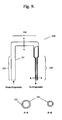
- FIG. 9 shows a seventh embodiment of the present invention with shrunk cross-section of the liquid line.
- FIG. 3 shows the first embodiment of the present invention.
- the flow path of the transport line 100 has sequential three sections: a vapor line 103 , a condensation section 104 , and a liquid line 105 .
- the inner wall of the tubing 101 of the condensation section and liquid line is made with grooved microchannels 102 , which can be made by extrusion molding during the fabrication of the tubing 101 .
- the grooved microchannel has a hydraulic diameter smaller than the 500 ⁇ m.
- the cross-section of the groove can be triangular, rectangular, trapezoidal, wavy, or others.
- a plug 106 is inserted into the core of the liquid line 105 to reduce its effective cross-sectional area to only the groove microchannels, to enhance the pumping force.
- the plug 106 can be fabricated with metal, plastic or other heat resistant materials.
- the bottom corners of the grooved microchannels as shown in A-A section view help to collect the condensed liquid and convey it to the liquid line section.
- the liquid can be effectively pumped with capillary action back to the wick (not shown) in the main body of the two-phase heat dissipation device.
- a capillary material 107 is optionally inserted. The capillary material 107 provides smoother connection with the wick (not shown) in the main body of the two-phase heat dissipation device.
- the vapor line section 103 can be a tube only or inserted with a grooved microchannels.
- the condensation section 104 is inserted with a grooved microchannels, which has a cross-section shown in cross-section A-A; the upper part of the liquid line 105 has a cross-section B-B; and, if the capillary material 107 is inserted, the lower part of the liquid line 105 has a cross-section C-C.
- the grooved microchannels can also be fabricated on the surface of the plug 106 .
- FIG. 4 shows a second embodiment of the present invention. This embodiment differs from the first embodiment in that a layer of wire mesh 109 is added to cover the grooved microchannels 102 for at least the condensation section 104 , as shown in cross-section A-A, to improve the pumping ability.
- the material of the wire mesh can be metals or nonmetals.
- FIG. 5 shows a third embodiment of the present invention.
- the grooved microchannels are fabricated with a layer of a corrugated wire mesh to line in along the inner wall of the tubing 101 of the transport line.
- the vapor section 103 can be a tube only or inserted with a corrugated wire mesh as shown in the cross-section A-A
- the condensation section 104 has a cross-section A-A with corrugated wire mesh lining 108 .
- the liquid line section has a cross-section B-B with corrugated wire mesh enclosing a plug 106 which reduces the effective cross-sectional area for the liquid to flow.
- the wire mesh is corrugated with a cross-section shape either of triangular, rectangular, trapezoidal, wavy, or other groove shape with equivalent function.
- the corrugated wire mesh is basically inserted into the condensation section 104 and liquid line 105 .
- a plug 106 is optionally inserted as a core in the liquid line 105 to reduce its effective cross-sectional area.
- An additional layer of wire mesh 109 can be optionally placed against the corrugated wire mesh 108 to form closed grooved microchannels in the condensation section 104 , as shown in cross-section A′-A′, to improve the pumping ability.
- the material of the wire mesh can be metals or nonmetals.
- FIG. 6 shows a fourth embodiment of the invention.
- the structure is similar to FIG. 3 with the same reference numerals denoting the corresponding parts. The only difference is that the plug 106 in the liquid line 105 in FIG. 3 is removed.
- the optional capillary material 107 provides smoother connection with the wick (not shown) in the main body of the two-phase heat dissipation device.
- FIG. 7 shows a fifth embodiment of the invention.
- the structure is similar to FIG. 4 with the same reference numerals denoting the corresponding parts. The only difference is that the plug 106 in the liquid line 105 in FIG. 4 is removed.
- the optional capillary material 107 provides smoother connection with the wick (not shown) in the main body of the two-phase heat dissipation device.
- the layer of wire mesh 109 covers at least the condensation section 104 and the liquid line 105 to improve the pumping ability.
- FIG. 8 shows a sixth embodiment of the invention.
- the structure is similar to FIG. 5 with the same reference numerals denoting the corresponding parts. The only difference is that the plug 106 in the liquid line 105 in FIG. 5 is removed.
- the optional capillary material 107 provides smoother connection with the wick (not shown) in the main body of the two-phase heat dissipation device.
- an additional layer of wire mesh 109 can be placed inside the corrugated wire mesh to form closed microchannels in the condensation section 104 and the liquid line 105 (as shown in section A′-A′ of FIG. 5 ) to improve the pumping ability.
- FIG. 9 shows a seventh embodiment of the present invention.
- the inner wall of the tubing 101 of the condensation section 104 , and the liquid line 105 has grooved microchannels as shown in cross-section A-A, and the liquid section 105 has a cross-section B-B which is made smaller than that of the condensation section 104 as shown in the cross-section A-A.
- a layer of wire mesh 109 can be added to cover the grooved microchannels 102 for at least the condensation section 104 (not shown).
- the shrunk liquid line 105 enhances capillary action for the coolant recycling.
- a plug can be inserted in the shrunk liquid line 105 (not shown) to further reduce its effective cross-section area
- An optional capillary material 107 can be added (as shown in FIG. 8 ) in the end of the liquid line 105 .
- FIG. 105 Other embodiments having a smaller effective cross0section area of the liquid line 105 can be made without grooved mnicrochannels on the inner wall of the transport line (not shown). This can be achieved by simply inserting a plug 106 having a size slightly smaller than of the transport line into the liquid line 105 . The small gap between the non-grooved inner wall surface of the evaporator. Alternatively, this can be achieved by shrinking the liquid line 105 . In addition, a plug can be inserted into the shrunk liquid line to further reduce its effective cross-sectional area. Again, a layer of wire mesh 109 can be added to cover the inner surface of at least the condensation section 104 . An optional capillary material 107 can be added in the end of the liquid line 105 .
Landscapes
- Engineering & Computer Science (AREA)
- Physics & Mathematics (AREA)
- General Engineering & Computer Science (AREA)
- Thermal Sciences (AREA)
- Sustainable Development (AREA)
- Mechanical Engineering (AREA)
- Life Sciences & Earth Sciences (AREA)
- Condensed Matter Physics & Semiconductors (AREA)
- General Physics & Mathematics (AREA)
- Computer Hardware Design (AREA)
- Microelectronics & Electronic Packaging (AREA)
- Power Engineering (AREA)
- Cooling Or The Like Of Semiconductors Or Solid State Devices (AREA)
Abstract
Grooved microchannels are used to enhance the capillary action in the transport line of two-phase heat dissipation devices, such as loop heat pipes, capillary pump loops, or spray cooling devices, or others. Efficient heat dissipations achieved by enhancing the capillary pumping force for the liquid flow without significantly increasing the friction force. The effective cross-sectional area of the liquid line is made smaller than that of the condensation section, either by inserting a plug or shrinking the liquid line, to provide additional pumping force for the coolant recycling.
Description
- 1. Field of the Invention
- The invention related to two-phase heat dissipation devices, particularly to the transport line of loop heat pipes, capillary pump loops, spray cooling devices or others. The two-phase heat dissipation device is sued for heat removal of heat generating devices, such as the central processing unit (CPU) or other integrated circuit (IC) chips.
- 2. Brief Description of Related Art
- As electronic technology advances, more electronic function is performed in a smaller area on a semiconductor chip. More electronic function is invariably accompanied with temperature increase which may damage the chip. To maintain a safe temperature, it is necessary to remove the heat generated in the chip at the chip mount.
- A widely used method for cooling the chip mount is to utilize the two-phase heat transfer during phase transition between liquid phase and vapor phase of a coolant. In this method, a vaporization section vaporizes the coolant and carries away a large amount of heat energy, and the vapor fills the originally evacuated space. In the condensation section, the vapor condenses into liquid for recycling and releases a large amount of heat energy. The heat pipe is a commonly applied heat dissipation device in this category. However in the traditional heat pipe, the vapor and the recycling liquid move in opposite directions. This impedes the recycling capillary pumping action and tends to limit the maximum heat dissipation capability of the heat pipe.
-
FIG. 1 shows a prior art to remedy this problem, using a loop heat pipe (LHP). The LHP comprises sequentially anevaporator 11, awick 12, avapor conduit 13, acondensation section 14, aliquid line 15, and acompensation chamber 16. The principle of operation is similar to that of a traditional heat pipe except that the vapor and the liquid flow in single way along a guiding loop. The operation still depends on the capillary action. The liquid compensation chamber is used to compensate the dispersion of the liquid in the loop to avoid the evaporator drying out. -
FIG. 2 shows another prior art disclosed in U.S. Pat. No. 6,381,135. The LHP 200 has anevaporator 212 placed on a heat-generatingdevice 204 on top of asubstrate 202. Athermal interface material 206 is placed between thedevice 204 and theevaporator 212. Theevaporator 212 comprises awick 213, one end of which is connected to aliquid line 214, which also has a wick (not shown). The second wick need not be the same as the first wick and may be of sintered metal powder, metallic wire mesh, or packed spherical particles. Thevapor line 216 is simply a hollow tube. Thecondenser 218 is a hollow block of metal, which can be mounted with fins to dissipate heat. Thecondenser 218 may have athird wick 219, which need not be the same as the first two wicks. The drawback of this structure is that the wicks in thecondenser 218 and theliquid line 214 increase the friction to the liquid flow and hence retard coolant recycling. Therefore, the evaporator tends to dry out at high heat dissipation and limit the heat cooling capability. For the reason that the volume flow rate of the vapor far exceeds that of the liquid, theliquid line 214 requires much smaller cross-sectional area than thevapor line 216. When the liquid section and the vapor section use the same large tubing, the liquid line cannot provide additional capillary force. If both sections use the same small tubing, the vapor speed and the friction in the vapor line becomes excessive. - The object of this invention is to provide efficient flow of a coolant in a transport line for loop heat pipes, capillary pump loops or spray cooling devices. Another object of this invention is to provide additional pumping force for the liquid flow without significantly increasing the friction force.
- These objectives are achieved by using grooved microchannels in the liquid line. Grooved microchannels can be optionally made in the inner surface of the condensation section. Further, a plug can be inserted in the liquid line to reduce its effective cross-sectional area to enhance the pumping force. Another way is to shrink the liquid line section to reduce its effective cross-sectional area to enhance the pumping force. The grooved microchannels in the liquid line provide additional pumping force for coolant recycling with limited friction force.
- The grooved microchannels can be constructed on the inner surface of the tube by means of extrusion molding of the tube, or by lining a groove-corrugated wire mesh along the inner wall of the transport line.
-
FIG. 1 shows a prior art loop heat pipe. -
FIG. 2 shows a second prior loop heat pipe disclosed in U.S. Pat. No. 6,381,135 -
FIG. 3 shows a first embodiment of the present invention with grooved microchannels along the inner wall of the condensation section and liquid line, and a plug inserted in the liquid line. -
FIG. 4 shows a second embodiment of the present invention with grooved microchannels covered with a layer of wire mesh along the inner wall of the condensation section and liquid line, and a plug inserted in the liquid line. -
FIG. 5 shows a third embodiment of the present invention with a groove-corrugated wire mesh lining along the inner wall of the condensation section and the liquid line to form microchannels, and a plug inserted in the liquid line. -
FIG. 6 shows a fourth embodiment of the present invention with grooved microchannels along the inner wall of the condensation section and liquid line, and without a plug in the liquid line. -
FIG. 7 shows a fifth embodiment of the present invention with grooved microchannels covered with a layer of wire mesh along the inner wall of the condensation section and liquid line, and without a plug in the liquid line. -
FIG. 8 shows a sixth embodiment of the present invention with a groove-corrugated wire mesh lining along the inner wall of the condensation section and the liquid line, and without a plug in the liquid line. -
FIG. 9 shows a seventh embodiment of the present invention with shrunk cross-section of the liquid line. -
FIG. 3 shows the first embodiment of the present invention. The flow path of thetransport line 100 has sequential three sections: avapor line 103, acondensation section 104, and aliquid line 105. The inner wall of thetubing 101 of the condensation section and liquid line is made withgrooved microchannels 102, which can be made by extrusion molding during the fabrication of thetubing 101. The grooved microchannel has a hydraulic diameter smaller than the 500 μm. The cross-section of the groove can be triangular, rectangular, trapezoidal, wavy, or others. Aplug 106 is inserted into the core of theliquid line 105 to reduce its effective cross-sectional area to only the groove microchannels, to enhance the pumping force. Theplug 106 can be fabricated with metal, plastic or other heat resistant materials. The bottom corners of the grooved microchannels as shown in A-A section view help to collect the condensed liquid and convey it to the liquid line section. With the grooved microchannels closed by aplug 106 in theliquid line 105, the liquid can be effectively pumped with capillary action back to the wick (not shown) in the main body of the two-phase heat dissipation device. At the end of theliquid section 105, acapillary material 107 is optionally inserted. Thecapillary material 107 provides smoother connection with the wick (not shown) in the main body of the two-phase heat dissipation device. Thevapor line section 103 can be a tube only or inserted with a grooved microchannels. Thecondensation section 104 is inserted with a grooved microchannels, which has a cross-section shown in cross-section A-A; the upper part of theliquid line 105 has a cross-section B-B; and, if thecapillary material 107 is inserted, the lower part of theliquid line 105 has a cross-section C-C. - The grooved microchannels can also be fabricated on the surface of the
plug 106. - With a reduced effective cross-sectional area in the
liquid section 105 by inserting aplug 106 and leaving the grooved microchannels only as a passage for the liquid, additional pumping force is provided for coolant recycling without significantly increasing friction in the liquid flow. -
FIG. 4 shows a second embodiment of the present invention. This embodiment differs from the first embodiment in that a layer ofwire mesh 109 is added to cover the groovedmicrochannels 102 for at least thecondensation section 104, as shown in cross-section A-A, to improve the pumping ability. The material of the wire mesh can be metals or nonmetals. -
FIG. 5 shows a third embodiment of the present invention. The grooved microchannels are fabricated with a layer of a corrugated wire mesh to line in along the inner wall of thetubing 101 of the transport line. Thevapor section 103 can be a tube only or inserted with a corrugated wire mesh as shown in the cross-section A-A, Thecondensation section 104 has a cross-section A-A with corrugatedwire mesh lining 108. The liquid line section has a cross-section B-B with corrugated wire mesh enclosing aplug 106 which reduces the effective cross-sectional area for the liquid to flow. The wire mesh is corrugated with a cross-section shape either of triangular, rectangular, trapezoidal, wavy, or other groove shape with equivalent function. The corrugated wire mesh is basically inserted into thecondensation section 104 andliquid line 105. Aplug 106 is optionally inserted as a core in theliquid line 105 to reduce its effective cross-sectional area. An additional layer ofwire mesh 109 can be optionally placed against thecorrugated wire mesh 108 to form closed grooved microchannels in thecondensation section 104, as shown in cross-section A′-A′, to improve the pumping ability. The material of the wire mesh can be metals or nonmetals. -
FIG. 6 shows a fourth embodiment of the invention. The structure is similar toFIG. 3 with the same reference numerals denoting the corresponding parts. The only difference is that theplug 106 in theliquid line 105 inFIG. 3 is removed. The optionalcapillary material 107 provides smoother connection with the wick (not shown) in the main body of the two-phase heat dissipation device. -
FIG. 7 shows a fifth embodiment of the invention. The structure is similar toFIG. 4 with the same reference numerals denoting the corresponding parts. The only difference is that theplug 106 in theliquid line 105 inFIG. 4 is removed. The optionalcapillary material 107 provides smoother connection with the wick (not shown) in the main body of the two-phase heat dissipation device. In this embodiment, the layer ofwire mesh 109 covers at least thecondensation section 104 and theliquid line 105 to improve the pumping ability. -
FIG. 8 shows a sixth embodiment of the invention. The structure is similar toFIG. 5 with the same reference numerals denoting the corresponding parts. The only difference is that theplug 106 in theliquid line 105 inFIG. 5 is removed. The optionalcapillary material 107 provides smoother connection with the wick (not shown) in the main body of the two-phase heat dissipation device. Again, an additional layer ofwire mesh 109 can be placed inside the corrugated wire mesh to form closed microchannels in thecondensation section 104 and the liquid line 105 (as shown in section A′-A′ ofFIG. 5 ) to improve the pumping ability. -
FIG. 9 shows a seventh embodiment of the present invention. The inner wall of thetubing 101 of thecondensation section 104, and theliquid line 105 has grooved microchannels as shown in cross-section A-A, and theliquid section 105 has a cross-section B-B which is made smaller than that of thecondensation section 104 as shown in the cross-section A-A. Also, a layer ofwire mesh 109 can be added to cover the groovedmicrochannels 102 for at least the condensation section 104 (not shown). The shrunkliquid line 105 enhances capillary action for the coolant recycling. In addition, a plug can be inserted in the shrunk liquid line 105 (not shown) to further reduce its effective cross-section area An optionalcapillary material 107 can be added (as shown inFIG. 8 ) in the end of theliquid line 105. - Other embodiments having a smaller effective cross0section area of the
liquid line 105 can be made without grooved mnicrochannels on the inner wall of the transport line (not shown). This can be achieved by simply inserting aplug 106 having a size slightly smaller than of the transport line into theliquid line 105. The small gap between the non-grooved inner wall surface of the evaporator. Alternatively, this can be achieved by shrinking theliquid line 105. In addition, a plug can be inserted into the shrunk liquid line to further reduce its effective cross-sectional area. Again, a layer ofwire mesh 109 can be added to cover the inner surface of at least thecondensation section 104. An optionalcapillary material 107 can be added in the end of theliquid line 105. - While the preferred embodiments of the invention have been described, it will be apparent to those skilled in the art, the various modifications may be made in the embodiments without departing from the spirit of the present invention Such modifications are all within the scope of the present invention.
Claims (21)
1. A transport line for use in a two-phase dissipation device, comprising:
a vapor line section for flowing a coolant in vapor phase from an evaporator in the main body of said two-phase heat dissipation device, a condensation section for condensing the vapor phase from said vapor section into liquid phase, and a liquid line section for refluxing said liquid phase coolant from said condenser section back to said evaporator; and
grooved microchannels made along the inner wall of said liquid line section to enhance capillary action.
2. The transport line for use in a two-phase heat dissipation device as described in claim 1 , further comprising:
grooved microchannels made along the inner wall of said condensation section to enhance capillary action.
3. The transport line as described in claim 2 , further comprising a layer of wire mesh covering said grooved microchannels.
4. The transport line as described in claim 1 , wherein the cross-section of said transport line is circular.
5. The transport line as described in claim 1 , wherein said grooved microchannels have a cross-section selected from the group consisting of: V-shaped, triangular, rectangular, trapezoidal, and wavy.
6. The transport line as described in claim 1 , wherein said grooved microchannels are formed by corrugating the inner wall of said section.
7. The transport line as described in claim 1 , wherein said grooved microchannels are formed by lining the inner wall of said section with corrugated wire mesh.
8. The transport line as described in claim 7 , further comprising a layer of wire mesh placed against said corrugated wire mesh to form closed grooved microchannels.
9. The transport line as described in claim 1 , further comprising a capillary material inserted in said liquid line section.
10. The transport line as described in claim 1 , further comprising a plug, inserted in said liquid line section to make an effective cross-sectional area smaller.
11. The transport line as described in claim 10 wherein said grooved microchannels are formed on the surface of said plug.
12. The transport line as described in claim 11 , further comprising a capillary material inserted in said liquid line section.
13. The transport line as described in claim 1 , wherein said liquid line section shrinks to make an effective cross-sectional area smaller.
14. The transport line as described in claim 13 , further comprising a plug, inserted in said liquid line section to further make an effective cross-sectional area smaller.
15. The transport line as described in claim 13 , further comprising a capillary material inserted in said liquid line section.
16. A transport line for use in a twO-phase heat dissipation device, comprising:
a vapor line section for flowing a coolant in vapor phase from an evaporator in the main body of said tw0-phase heat dissipation device, a condensation section for condensing the vapor phase from said vapor section into liquid phase, and a liquid line section for refluxing said liquid phase coolant from said condenser section back to said evaporator, and the effective cross-sectional area of said liquid line section is smaller than the cross-sectional area of said vapor section.
17. The transport line as described in claim 16 , further comprising a later of wire mesh placed against the inner wall of at least said condensation section.
18. The transport line as described in claim 16 , wherein the effective cross-sectional area of said liquid line section is made smaller by inserting a plug.
19. The transport line as described in claim 16 , wherein the effective cross-sectional area of said liquid line section is made smaller by shrinking said liquid line section.
20. The transport line as described in claim 16 , further comprising a capillary material inserted in said liquid line section.
21. The transport line as described in claim 20 , wherein the effective cross-sectional area of said liquid line section is made further smaller by inserting a plug.
Applications Claiming Priority (6)
| Application Number | Priority Date | Filing Date | Title |
|---|---|---|---|
| TW092127907 | 2003-10-08 | ||
| TW92127907 | 2003-10-08 | ||
| TW093108606 | 2004-03-30 | ||
| TW93108606 | 2004-03-30 | ||
| TW093112391 | 2004-05-03 | ||
| TW093112391A TW200513626A (en) | 2004-05-03 | 2004-05-03 | Transport line with grooved microchannels for two-phase heat dissipation devices |
Publications (1)
| Publication Number | Publication Date |
|---|---|
| US20050077030A1 true US20050077030A1 (en) | 2005-04-14 |
Family
ID=34426725
Family Applications (1)
| Application Number | Title | Priority Date | Filing Date |
|---|---|---|---|
| US10/936,065 Abandoned US20050077030A1 (en) | 2003-10-08 | 2004-09-09 | Transport line with grooved microchannels for two-phase heat dissipation on devices |
Country Status (1)
| Country | Link |
|---|---|
| US (1) | US20050077030A1 (en) |
Cited By (33)
| Publication number | Priority date | Publication date | Assignee | Title |
|---|---|---|---|---|
| US20060162906A1 (en) * | 2005-01-21 | 2006-07-27 | Chu-Wan Hong | Heat pipe with screen mesh wick structure |
| US20060175044A1 (en) * | 2005-02-10 | 2006-08-10 | Chin-Wei Lee | Heat dissipating tube sintered with copper powders |
| US20060196646A1 (en) * | 2005-03-01 | 2006-09-07 | Myers Alan M | Integrated circuit coolant microchannel with compliant cover |
| US20060272802A1 (en) * | 2005-06-07 | 2006-12-07 | Hitachi Cable, Ltd. | Cooling plate |
| US20060283577A1 (en) * | 2005-06-17 | 2006-12-21 | Tay-Jian Liu | Loop-type heat exchange device |
| US20070133173A1 (en) * | 2005-12-13 | 2007-06-14 | Industrial Technology Research Institute | Compact spray cooling module |
| US20070240854A1 (en) * | 2006-04-14 | 2007-10-18 | Foxconn Technology Co., Ltd. | Heat pipe and method for producing the same |
| US20070240858A1 (en) * | 2006-04-14 | 2007-10-18 | Foxconn Technology Co., Ltd. | Heat pipe with composite capillary wick structure |
| US20070240855A1 (en) * | 2006-04-14 | 2007-10-18 | Foxconn Technology Co., Ltd. | Heat pipe with composite capillary wick structure |
| US20070240857A1 (en) * | 2006-04-14 | 2007-10-18 | Foxconn Technology Co., Ltd. | Heat pipe with capillary wick |
| US20070277963A1 (en) * | 2006-06-02 | 2007-12-06 | Foxconn Technology Co., Ltd. | Heat pipe |
| US20080105406A1 (en) * | 2006-11-03 | 2008-05-08 | Foxconn Technology Co., Ltd. | Heat pipe with variable grooved-wick structure and method for manufacturing the same |
| EP1935050A1 (en) * | 2005-11-08 | 2008-06-25 | Byd Company Limited | A heat dissipating device for a battery pack, and a battery pack using the same |
| CN100401508C (en) * | 2005-09-14 | 2008-07-09 | 赵耀华 | High-performance passive phase-change radiation system and its application |
| US20090020268A1 (en) * | 2007-07-20 | 2009-01-22 | Foxconn Technology Co., Ltd. | Grooved heat pipe and method for manufacturing the same |
| US20090097206A1 (en) * | 2007-10-15 | 2009-04-16 | Kabushiki Kaisha Toshiba | Loop heat pipe and electronic equipment |
| US20090314472A1 (en) * | 2008-06-18 | 2009-12-24 | Chul Ju Kim | Evaporator For Loop Heat Pipe System |
| US20090321055A1 (en) * | 2008-06-26 | 2009-12-31 | Inventec Corporation | Loop heat pipe |
| US20100236761A1 (en) * | 2009-03-19 | 2010-09-23 | Acbel Polytech Inc. | Liquid cooled heat sink for multiple separated heat generating devices |
| US20110098599A1 (en) * | 2005-09-30 | 2011-04-28 | Intuity Medical, Inc. | Fluid Sample Transport Devices and Methods |
| US20130133863A1 (en) * | 2011-11-30 | 2013-05-30 | Palo Alto Research Center Incorporated | Co-Extruded Microchannel Heat Pipes |
| US20140138058A1 (en) * | 2012-11-20 | 2014-05-22 | Elwha Llc | Heat pipe having a channeled heat transfer array |
| JP2015064118A (en) * | 2013-09-24 | 2015-04-09 | 富士通株式会社 | Cooling apparatus, information processor, and cooling method |
| US9120190B2 (en) | 2011-11-30 | 2015-09-01 | Palo Alto Research Center Incorporated | Co-extruded microchannel heat pipes |
| US20170273360A1 (en) * | 2017-05-17 | 2017-09-28 | Rai Strategic Holdings, Inc. | Aerosol delivery device |
| CN110145953A (en) * | 2019-05-28 | 2019-08-20 | 苏州科技大学 | A kind of separate type micro-channel capillary siphon heat exchanger |
| US10463077B2 (en) | 2016-06-24 | 2019-11-05 | Altria Client Services Llc | Cartridge for e-vaping device with open-microchannels |
| US20200149823A1 (en) * | 2018-11-09 | 2020-05-14 | Furukawa Electric Co., Ltd. | Heat pipe |
| CN113224018A (en) * | 2021-06-03 | 2021-08-06 | 北京工业大学 | Low-temperature-rise local-encryption type sine corrugated micro-channel radiator |
| US11112186B2 (en) * | 2019-04-18 | 2021-09-07 | Furukawa Electric Co., Ltd. | Heat pipe heatsink with internal structural support plate |
| US11207478B2 (en) | 2016-03-25 | 2021-12-28 | Rai Strategic Holdings, Inc. | Aerosol production assembly including surface with micro-pattern |
| CN114916193A (en) * | 2022-04-24 | 2022-08-16 | 大连保税区金宝至电子有限公司 | Method for counter-gravity liquid delivery and heat sink |
| US11986298B2 (en) | 2005-09-30 | 2024-05-21 | Intuity Medical, Inc. | Devices and methods for facilitating fluid transport |
Citations (10)
| Publication number | Priority date | Publication date | Assignee | Title |
|---|---|---|---|---|
| US3734173A (en) * | 1969-01-28 | 1973-05-22 | Messerschmitt Boelkow Blohm | Arrangement for transmitting heat |
| US4467861A (en) * | 1982-10-04 | 1984-08-28 | Otdel Fiziko-Tekhnicheskikh Problem Energetiki Uralskogo Nauchnogo Tsentra Akademii Nauk Sssr | Heat-transporting device |
| US4489777A (en) * | 1982-01-21 | 1984-12-25 | Del Bagno Anthony C | Heat pipe having multiple integral wick structures |
| US5203399A (en) * | 1990-05-16 | 1993-04-20 | Kabushiki Kaisha Toshiba | Heat transfer apparatus |
| US5303768A (en) * | 1993-02-17 | 1994-04-19 | Grumman Aerospace Corporation | Capillary pump evaporator |
| US5725049A (en) * | 1995-10-31 | 1998-03-10 | The United States Of America As Represented By The Administrator Of The National Aeronautics And Space Administration | Capillary pumped loop body heat exchanger |
| US6269865B1 (en) * | 1997-08-22 | 2001-08-07 | Bin-Juine Huang | Network-type heat pipe device |
| US6330907B1 (en) * | 1997-03-07 | 2001-12-18 | Mitsubishi Denki Kabushiki Kaisha | Evaporator and loop-type heat pipe using the same |
| US20020007937A1 (en) * | 2000-06-30 | 2002-01-24 | Kroliczek Edward J. | Phase control in the capillary evaporators |
| US6615912B2 (en) * | 2001-06-20 | 2003-09-09 | Thermal Corp. | Porous vapor valve for improved loop thermosiphon performance |
-
2004
- 2004-09-09 US US10/936,065 patent/US20050077030A1/en not_active Abandoned
Patent Citations (10)
| Publication number | Priority date | Publication date | Assignee | Title |
|---|---|---|---|---|
| US3734173A (en) * | 1969-01-28 | 1973-05-22 | Messerschmitt Boelkow Blohm | Arrangement for transmitting heat |
| US4489777A (en) * | 1982-01-21 | 1984-12-25 | Del Bagno Anthony C | Heat pipe having multiple integral wick structures |
| US4467861A (en) * | 1982-10-04 | 1984-08-28 | Otdel Fiziko-Tekhnicheskikh Problem Energetiki Uralskogo Nauchnogo Tsentra Akademii Nauk Sssr | Heat-transporting device |
| US5203399A (en) * | 1990-05-16 | 1993-04-20 | Kabushiki Kaisha Toshiba | Heat transfer apparatus |
| US5303768A (en) * | 1993-02-17 | 1994-04-19 | Grumman Aerospace Corporation | Capillary pump evaporator |
| US5725049A (en) * | 1995-10-31 | 1998-03-10 | The United States Of America As Represented By The Administrator Of The National Aeronautics And Space Administration | Capillary pumped loop body heat exchanger |
| US6330907B1 (en) * | 1997-03-07 | 2001-12-18 | Mitsubishi Denki Kabushiki Kaisha | Evaporator and loop-type heat pipe using the same |
| US6269865B1 (en) * | 1997-08-22 | 2001-08-07 | Bin-Juine Huang | Network-type heat pipe device |
| US20020007937A1 (en) * | 2000-06-30 | 2002-01-24 | Kroliczek Edward J. | Phase control in the capillary evaporators |
| US6615912B2 (en) * | 2001-06-20 | 2003-09-09 | Thermal Corp. | Porous vapor valve for improved loop thermosiphon performance |
Cited By (48)
| Publication number | Priority date | Publication date | Assignee | Title |
|---|---|---|---|---|
| US20060162906A1 (en) * | 2005-01-21 | 2006-07-27 | Chu-Wan Hong | Heat pipe with screen mesh wick structure |
| US20060175044A1 (en) * | 2005-02-10 | 2006-08-10 | Chin-Wei Lee | Heat dissipating tube sintered with copper powders |
| US7243705B2 (en) * | 2005-03-01 | 2007-07-17 | Intel Corporation | Integrated circuit coolant microchannel with compliant cover |
| US20060196646A1 (en) * | 2005-03-01 | 2006-09-07 | Myers Alan M | Integrated circuit coolant microchannel with compliant cover |
| US20070230116A1 (en) * | 2005-03-01 | 2007-10-04 | Myers Alan M | Integrated circuit coolant microchannel with compliant cover |
| US20060272802A1 (en) * | 2005-06-07 | 2006-12-07 | Hitachi Cable, Ltd. | Cooling plate |
| US7552759B2 (en) | 2005-06-17 | 2009-06-30 | Foxconn Technology Co., Ltd. | Loop-type heat exchange device |
| US20060283577A1 (en) * | 2005-06-17 | 2006-12-21 | Tay-Jian Liu | Loop-type heat exchange device |
| CN100401508C (en) * | 2005-09-14 | 2008-07-09 | 赵耀华 | High-performance passive phase-change radiation system and its application |
| US20110098599A1 (en) * | 2005-09-30 | 2011-04-28 | Intuity Medical, Inc. | Fluid Sample Transport Devices and Methods |
| US11986298B2 (en) | 2005-09-30 | 2024-05-21 | Intuity Medical, Inc. | Devices and methods for facilitating fluid transport |
| EP1935050A4 (en) * | 2005-11-08 | 2008-08-27 | Byd Co Ltd | A heat dissipating device for a battery pack, and a battery pack using the same |
| EP1935050A1 (en) * | 2005-11-08 | 2008-06-25 | Byd Company Limited | A heat dissipating device for a battery pack, and a battery pack using the same |
| US20070133173A1 (en) * | 2005-12-13 | 2007-06-14 | Industrial Technology Research Institute | Compact spray cooling module |
| US20070240857A1 (en) * | 2006-04-14 | 2007-10-18 | Foxconn Technology Co., Ltd. | Heat pipe with capillary wick |
| US20070240855A1 (en) * | 2006-04-14 | 2007-10-18 | Foxconn Technology Co., Ltd. | Heat pipe with composite capillary wick structure |
| US20070240858A1 (en) * | 2006-04-14 | 2007-10-18 | Foxconn Technology Co., Ltd. | Heat pipe with composite capillary wick structure |
| US20070240854A1 (en) * | 2006-04-14 | 2007-10-18 | Foxconn Technology Co., Ltd. | Heat pipe and method for producing the same |
| US7866374B2 (en) | 2006-04-14 | 2011-01-11 | Foxconn Technology Co., Ltd. | Heat pipe with capillary wick |
| US7743819B2 (en) | 2006-04-14 | 2010-06-29 | Foxconn Technology Co., Ltd. | Heat pipe and method for producing the same |
| US20070277963A1 (en) * | 2006-06-02 | 2007-12-06 | Foxconn Technology Co., Ltd. | Heat pipe |
| US7726384B2 (en) | 2006-06-02 | 2010-06-01 | Foxconn Technology Co., Ltd. | Heat pipe |
| CN100498186C (en) * | 2006-06-02 | 2009-06-10 | 富准精密工业(深圳)有限公司 | Hot pipe |
| US20080105406A1 (en) * | 2006-11-03 | 2008-05-08 | Foxconn Technology Co., Ltd. | Heat pipe with variable grooved-wick structure and method for manufacturing the same |
| US20090020268A1 (en) * | 2007-07-20 | 2009-01-22 | Foxconn Technology Co., Ltd. | Grooved heat pipe and method for manufacturing the same |
| US20090097206A1 (en) * | 2007-10-15 | 2009-04-16 | Kabushiki Kaisha Toshiba | Loop heat pipe and electronic equipment |
| US20090314472A1 (en) * | 2008-06-18 | 2009-12-24 | Chul Ju Kim | Evaporator For Loop Heat Pipe System |
| US20090321055A1 (en) * | 2008-06-26 | 2009-12-31 | Inventec Corporation | Loop heat pipe |
| US20100236761A1 (en) * | 2009-03-19 | 2010-09-23 | Acbel Polytech Inc. | Liquid cooled heat sink for multiple separated heat generating devices |
| US10160071B2 (en) | 2011-11-30 | 2018-12-25 | Palo Alto Research Center Incorporated | Co-extruded microchannel heat pipes |
| US9120190B2 (en) | 2011-11-30 | 2015-09-01 | Palo Alto Research Center Incorporated | Co-extruded microchannel heat pipes |
| US20130133863A1 (en) * | 2011-11-30 | 2013-05-30 | Palo Alto Research Center Incorporated | Co-Extruded Microchannel Heat Pipes |
| US10371468B2 (en) * | 2011-11-30 | 2019-08-06 | Palo Alto Research Center Incorporated | Co-extruded microchannel heat pipes |
| US20140138058A1 (en) * | 2012-11-20 | 2014-05-22 | Elwha Llc | Heat pipe having a channeled heat transfer array |
| JP2015064118A (en) * | 2013-09-24 | 2015-04-09 | 富士通株式会社 | Cooling apparatus, information processor, and cooling method |
| US11207478B2 (en) | 2016-03-25 | 2021-12-28 | Rai Strategic Holdings, Inc. | Aerosol production assembly including surface with micro-pattern |
| US11911561B2 (en) | 2016-03-25 | 2024-02-27 | Rai Strategic Holdings, Inc. | Aerosol production assembly including surface with micro-pattern |
| US11951250B2 (en) | 2016-06-24 | 2024-04-09 | Altria Client Services Llc | Cartridge for e-vaping device with open-microchannels |
| US10463077B2 (en) | 2016-06-24 | 2019-11-05 | Altria Client Services Llc | Cartridge for e-vaping device with open-microchannels |
| US11471624B2 (en) | 2016-06-24 | 2022-10-18 | Altria Client Services Llc | Cartridge for e-vaping device with open-microchannels |
| US11297876B2 (en) * | 2017-05-17 | 2022-04-12 | Rai Strategic Holdings, Inc. | Aerosol delivery device |
| US20170273360A1 (en) * | 2017-05-17 | 2017-09-28 | Rai Strategic Holdings, Inc. | Aerosol delivery device |
| US10976112B2 (en) * | 2018-11-09 | 2021-04-13 | Furukawa Electric Co., Ltd. | Heat pipe |
| US20200149823A1 (en) * | 2018-11-09 | 2020-05-14 | Furukawa Electric Co., Ltd. | Heat pipe |
| US11112186B2 (en) * | 2019-04-18 | 2021-09-07 | Furukawa Electric Co., Ltd. | Heat pipe heatsink with internal structural support plate |
| CN110145953A (en) * | 2019-05-28 | 2019-08-20 | 苏州科技大学 | A kind of separate type micro-channel capillary siphon heat exchanger |
| CN113224018A (en) * | 2021-06-03 | 2021-08-06 | 北京工业大学 | Low-temperature-rise local-encryption type sine corrugated micro-channel radiator |
| CN114916193A (en) * | 2022-04-24 | 2022-08-16 | 大连保税区金宝至电子有限公司 | Method for counter-gravity liquid delivery and heat sink |
Similar Documents
| Publication | Publication Date | Title |
|---|---|---|
| US20050077030A1 (en) | Transport line with grooved microchannels for two-phase heat dissipation on devices | |
| US7293601B2 (en) | Thermoduct | |
| US6381135B1 (en) | Loop heat pipe for mobile computers | |
| US7543630B2 (en) | Heat pipe incorporating outer and inner pipes | |
| US7011146B2 (en) | Microchannel heat pipe with parallel grooves for recycling coolant | |
| US20070062036A1 (en) | Method of filling and sealing working fluid within heat-dissipating device | |
| CA2272260C (en) | Thin, planar heat spreader | |
| US7422053B2 (en) | Vapor augmented heatsink with multi-wick structure | |
| US6525420B2 (en) | Semiconductor package with lid heat spreader | |
| US8490683B2 (en) | Flat plate type micro heat transport device | |
| US9230881B2 (en) | Heat sink for dissipating a thermal load | |
| US6675887B2 (en) | Multiple temperature sensitive devices using two heat pipes | |
| US20090151906A1 (en) | Heat sink with vapor chamber | |
| Chen et al. | The application of capillary pumped loop for cooling of electronic components | |
| US20060283577A1 (en) | Loop-type heat exchange device | |
| US20100018678A1 (en) | Vapor Chamber with Boiling-Enhanced Multi-Wick Structure | |
| US20070240858A1 (en) | Heat pipe with composite capillary wick structure | |
| US20070240852A1 (en) | Heat pipe with heat reservoirs at both evaporating and condensing sections thereof | |
| US20120227934A1 (en) | Heat pipe having a composite wick structure and method for making the same | |
| US9179577B2 (en) | Flat heat pipe and fabrication method thereof | |
| US9074824B2 (en) | Low-profile heat transfer device | |
| US8006747B2 (en) | Micro-chimney and thermosiphon die-level cooling | |
| US20050183847A1 (en) | Microchannel flat-plate heat pipe with parallel grooves for recycling coolant | |
| JP4382891B2 (en) | Flat heat pipe and manufacturing method thereof | |
| US20190154352A1 (en) | Loop heat pipe structure |
Legal Events
| Date | Code | Title | Description |
|---|---|---|---|
| STCB | Information on status: application discontinuation |
Free format text: ABANDONED -- FAILURE TO RESPOND TO AN OFFICE ACTION |