US20040228080A1 - Computer controlled display device - Google Patents
Computer controlled display device Download PDFInfo
- Publication number
- US20040228080A1 US20040228080A1 US10/742,438 US74243803A US2004228080A1 US 20040228080 A1 US20040228080 A1 US 20040228080A1 US 74243803 A US74243803 A US 74243803A US 2004228080 A1 US2004228080 A1 US 2004228080A1
- Authority
- US
- United States
- Prior art keywords
- ball
- socket
- assembly
- computer controlled
- moveable
- Prior art date
- Legal status (The legal status is an assumption and is not a legal conclusion. Google has not performed a legal analysis and makes no representation as to the accuracy of the status listed.)
- Granted
Links
- 230000033001 locomotion Effects 0.000 claims abstract description 58
- 239000000463 material Substances 0.000 claims description 43
- 229910052751 metal Inorganic materials 0.000 claims description 42
- 239000002184 metal Substances 0.000 claims description 42
- 239000004033 plastic Substances 0.000 claims description 39
- 229920003023 plastic Polymers 0.000 claims description 39
- 238000000429 assembly Methods 0.000 claims description 32
- 230000000712 assembly Effects 0.000 claims description 31
- 239000000919 ceramic Substances 0.000 claims description 10
- 229910001092 metal group alloy Inorganic materials 0.000 claims description 10
- 235000015895 biscuits Nutrition 0.000 description 45
- 230000007246 mechanism Effects 0.000 description 37
- 230000006835 compression Effects 0.000 description 27
- 238000007906 compression Methods 0.000 description 27
- 238000004519 manufacturing process Methods 0.000 description 18
- 238000005381 potential energy Methods 0.000 description 15
- 239000010935 stainless steel Substances 0.000 description 15
- 229910001220 stainless steel Inorganic materials 0.000 description 15
- 229910052782 aluminium Inorganic materials 0.000 description 14
- XAGFODPZIPBFFR-UHFFFAOYSA-N aluminium Chemical compound [Al] XAGFODPZIPBFFR-UHFFFAOYSA-N 0.000 description 14
- 238000010586 diagram Methods 0.000 description 14
- 239000004677 Nylon Substances 0.000 description 13
- 229920001778 nylon Polymers 0.000 description 13
- 230000008859 change Effects 0.000 description 12
- 238000005259 measurement Methods 0.000 description 9
- 239000002537 cosmetic Substances 0.000 description 8
- 150000002739 metals Chemical class 0.000 description 8
- 238000000034 method Methods 0.000 description 8
- 229920006362 Teflon® Polymers 0.000 description 7
- 230000005484 gravity Effects 0.000 description 7
- 230000003287 optical effect Effects 0.000 description 7
- 230000002093 peripheral effect Effects 0.000 description 7
- UONOETXJSWQNOL-UHFFFAOYSA-N tungsten carbide Chemical compound [W+]#[C-] UONOETXJSWQNOL-UHFFFAOYSA-N 0.000 description 7
- 239000000853 adhesive Substances 0.000 description 6
- 230000001070 adhesive effect Effects 0.000 description 6
- 239000003082 abrasive agent Substances 0.000 description 5
- 239000002131 composite material Substances 0.000 description 5
- 230000008878 coupling Effects 0.000 description 5
- 238000010168 coupling process Methods 0.000 description 5
- 238000005859 coupling reaction Methods 0.000 description 5
- 230000007423 decrease Effects 0.000 description 5
- 238000013461 design Methods 0.000 description 5
- 229920001971 elastomer Polymers 0.000 description 5
- 239000011152 fibreglass Substances 0.000 description 5
- 239000000314 lubricant Substances 0.000 description 5
- 229920000642 polymer Polymers 0.000 description 5
- 238000012545 processing Methods 0.000 description 5
- 238000012546 transfer Methods 0.000 description 5
- 244000261422 Lysimachia clethroides Species 0.000 description 4
- VYPSYNLAJGMNEJ-UHFFFAOYSA-N Silicium dioxide Chemical compound O=[Si]=O VYPSYNLAJGMNEJ-UHFFFAOYSA-N 0.000 description 4
- 230000005540 biological transmission Effects 0.000 description 4
- 230000000881 depressing effect Effects 0.000 description 4
- 230000006870 function Effects 0.000 description 4
- TWNQGVIAIRXVLR-UHFFFAOYSA-N oxo(oxoalumanyloxy)alumane Chemical compound O=[Al]O[Al]=O TWNQGVIAIRXVLR-UHFFFAOYSA-N 0.000 description 4
- 230000002829 reductive effect Effects 0.000 description 4
- 230000011664 signaling Effects 0.000 description 4
- 229910000831 Steel Inorganic materials 0.000 description 3
- 238000013459 approach Methods 0.000 description 3
- 230000008901 benefit Effects 0.000 description 3
- 230000003247 decreasing effect Effects 0.000 description 3
- 230000000694 effects Effects 0.000 description 3
- 239000012530 fluid Substances 0.000 description 3
- 239000011521 glass Substances 0.000 description 3
- 238000001746 injection moulding Methods 0.000 description 3
- 238000003754 machining Methods 0.000 description 3
- 238000012986 modification Methods 0.000 description 3
- 230000004048 modification Effects 0.000 description 3
- 239000010959 steel Substances 0.000 description 3
- 229910052727 yttrium Inorganic materials 0.000 description 3
- RTAQQCXQSZGOHL-UHFFFAOYSA-N Titanium Chemical compound [Ti] RTAQQCXQSZGOHL-UHFFFAOYSA-N 0.000 description 2
- 238000006243 chemical reaction Methods 0.000 description 2
- 238000010276 construction Methods 0.000 description 2
- 238000013500 data storage Methods 0.000 description 2
- 230000000994 depressogenic effect Effects 0.000 description 2
- 238000011161 development Methods 0.000 description 2
- 230000018109 developmental process Effects 0.000 description 2
- 238000006073 displacement reaction Methods 0.000 description 2
- 238000005516 engineering process Methods 0.000 description 2
- 239000002783 friction material Substances 0.000 description 2
- 239000003292 glue Substances 0.000 description 2
- 238000003780 insertion Methods 0.000 description 2
- 230000037431 insertion Effects 0.000 description 2
- 239000007788 liquid Substances 0.000 description 2
- 230000013011 mating Effects 0.000 description 2
- 239000002245 particle Substances 0.000 description 2
- 238000003825 pressing Methods 0.000 description 2
- 230000008569 process Effects 0.000 description 2
- 230000001681 protective effect Effects 0.000 description 2
- 239000000377 silicon dioxide Substances 0.000 description 2
- 230000003068 static effect Effects 0.000 description 2
- 238000003860 storage Methods 0.000 description 2
- 229910052719 titanium Inorganic materials 0.000 description 2
- 239000010936 titanium Substances 0.000 description 2
- 238000005303 weighing Methods 0.000 description 2
- 229920002799 BoPET Polymers 0.000 description 1
- RYGMFSIKBFXOCR-UHFFFAOYSA-N Copper Chemical compound [Cu] RYGMFSIKBFXOCR-UHFFFAOYSA-N 0.000 description 1
- 229920004943 Delrin® Polymers 0.000 description 1
- 239000005041 Mylar™ Substances 0.000 description 1
- 239000004698 Polyethylene Substances 0.000 description 1
- 239000004736 Ryton® Substances 0.000 description 1
- XUIMIQQOPSSXEZ-UHFFFAOYSA-N Silicon Chemical compound [Si] XUIMIQQOPSSXEZ-UHFFFAOYSA-N 0.000 description 1
- HCHKCACWOHOZIP-UHFFFAOYSA-N Zinc Chemical compound [Zn] HCHKCACWOHOZIP-UHFFFAOYSA-N 0.000 description 1
- 229910001297 Zn alloy Inorganic materials 0.000 description 1
- 230000009471 action Effects 0.000 description 1
- 229910045601 alloy Inorganic materials 0.000 description 1
- 239000000956 alloy Substances 0.000 description 1
- 238000005452 bending Methods 0.000 description 1
- 230000015556 catabolic process Effects 0.000 description 1
- 239000011248 coating agent Substances 0.000 description 1
- 238000000576 coating method Methods 0.000 description 1
- 238000004891 communication Methods 0.000 description 1
- 238000002788 crimping Methods 0.000 description 1
- 230000007547 defect Effects 0.000 description 1
- 238000006731 degradation reaction Methods 0.000 description 1
- 230000003292 diminished effect Effects 0.000 description 1
- 230000009977 dual effect Effects 0.000 description 1
- 239000000428 dust Substances 0.000 description 1
- 210000005069 ears Anatomy 0.000 description 1
- 238000002474 experimental method Methods 0.000 description 1
- 230000004907 flux Effects 0.000 description 1
- 239000008187 granular material Substances 0.000 description 1
- 239000004519 grease Substances 0.000 description 1
- 230000036541 health Effects 0.000 description 1
- 239000004973 liquid crystal related substance Substances 0.000 description 1
- 229910001338 liquidmetal Inorganic materials 0.000 description 1
- 230000007774 longterm Effects 0.000 description 1
- 230000001050 lubricating effect Effects 0.000 description 1
- 230000014759 maintenance of location Effects 0.000 description 1
- 238000007726 management method Methods 0.000 description 1
- 238000002844 melting Methods 0.000 description 1
- 230000008018 melting Effects 0.000 description 1
- 239000012528 membrane Substances 0.000 description 1
- 238000013508 migration Methods 0.000 description 1
- 230000005012 migration Effects 0.000 description 1
- 238000000465 moulding Methods 0.000 description 1
- 238000004806 packaging method and process Methods 0.000 description 1
- -1 polyethylene Polymers 0.000 description 1
- 229920000573 polyethylene Polymers 0.000 description 1
- 230000036316 preload Effects 0.000 description 1
- 230000000717 retained effect Effects 0.000 description 1
- 238000007665 sagging Methods 0.000 description 1
- 229910052710 silicon Inorganic materials 0.000 description 1
- 239000010703 silicon Substances 0.000 description 1
- 239000007787 solid Substances 0.000 description 1
- 239000000243 solution Substances 0.000 description 1
- 238000012360 testing method Methods 0.000 description 1
- 238000009423 ventilation Methods 0.000 description 1
- 125000000391 vinyl group Chemical group [H]C([*])=C([H])[H] 0.000 description 1
- 229920002554 vinyl polymer Polymers 0.000 description 1
- XLYOFNOQVPJJNP-UHFFFAOYSA-N water Substances O XLYOFNOQVPJJNP-UHFFFAOYSA-N 0.000 description 1
- 229910052725 zinc Inorganic materials 0.000 description 1
- 239000011701 zinc Substances 0.000 description 1
Images


Classifications
-
- G—PHYSICS
- G06—COMPUTING; CALCULATING OR COUNTING
- G06F—ELECTRIC DIGITAL DATA PROCESSING
- G06F1/00—Details not covered by groups G06F3/00 - G06F13/00 and G06F21/00
- G06F1/16—Constructional details or arrangements
- G06F1/1601—Constructional details related to the housing of computer displays, e.g. of CRT monitors, of flat displays
-
- F—MECHANICAL ENGINEERING; LIGHTING; HEATING; WEAPONS; BLASTING
- F16—ENGINEERING ELEMENTS AND UNITS; GENERAL MEASURES FOR PRODUCING AND MAINTAINING EFFECTIVE FUNCTIONING OF MACHINES OR INSTALLATIONS; THERMAL INSULATION IN GENERAL
- F16M—FRAMES, CASINGS OR BEDS OF ENGINES, MACHINES OR APPARATUS, NOT SPECIFIC TO ENGINES, MACHINES OR APPARATUS PROVIDED FOR ELSEWHERE; STANDS; SUPPORTS
- F16M11/00—Stands or trestles as supports for apparatus or articles placed thereon ; Stands for scientific apparatus such as gravitational force meters
- F16M11/02—Heads
- F16M11/04—Means for attachment of apparatus; Means allowing adjustment of the apparatus relatively to the stand
- F16M11/06—Means for attachment of apparatus; Means allowing adjustment of the apparatus relatively to the stand allowing pivoting
- F16M11/10—Means for attachment of apparatus; Means allowing adjustment of the apparatus relatively to the stand allowing pivoting around a horizontal axis
-
- F—MECHANICAL ENGINEERING; LIGHTING; HEATING; WEAPONS; BLASTING
- F16—ENGINEERING ELEMENTS AND UNITS; GENERAL MEASURES FOR PRODUCING AND MAINTAINING EFFECTIVE FUNCTIONING OF MACHINES OR INSTALLATIONS; THERMAL INSULATION IN GENERAL
- F16M—FRAMES, CASINGS OR BEDS OF ENGINES, MACHINES OR APPARATUS, NOT SPECIFIC TO ENGINES, MACHINES OR APPARATUS PROVIDED FOR ELSEWHERE; STANDS; SUPPORTS
- F16M11/00—Stands or trestles as supports for apparatus or articles placed thereon ; Stands for scientific apparatus such as gravitational force meters
- F16M11/02—Heads
- F16M11/04—Means for attachment of apparatus; Means allowing adjustment of the apparatus relatively to the stand
- F16M11/06—Means for attachment of apparatus; Means allowing adjustment of the apparatus relatively to the stand allowing pivoting
- F16M11/12—Means for attachment of apparatus; Means allowing adjustment of the apparatus relatively to the stand allowing pivoting in more than one direction
- F16M11/14—Means for attachment of apparatus; Means allowing adjustment of the apparatus relatively to the stand allowing pivoting in more than one direction with ball-joint
-
- F—MECHANICAL ENGINEERING; LIGHTING; HEATING; WEAPONS; BLASTING
- F16—ENGINEERING ELEMENTS AND UNITS; GENERAL MEASURES FOR PRODUCING AND MAINTAINING EFFECTIVE FUNCTIONING OF MACHINES OR INSTALLATIONS; THERMAL INSULATION IN GENERAL
- F16M—FRAMES, CASINGS OR BEDS OF ENGINES, MACHINES OR APPARATUS, NOT SPECIFIC TO ENGINES, MACHINES OR APPARATUS PROVIDED FOR ELSEWHERE; STANDS; SUPPORTS
- F16M11/00—Stands or trestles as supports for apparatus or articles placed thereon ; Stands for scientific apparatus such as gravitational force meters
- F16M11/20—Undercarriages with or without wheels
- F16M11/2007—Undercarriages with or without wheels comprising means allowing pivoting adjustment
- F16M11/2014—Undercarriages with or without wheels comprising means allowing pivoting adjustment around a vertical axis
-
- F—MECHANICAL ENGINEERING; LIGHTING; HEATING; WEAPONS; BLASTING
- F16—ENGINEERING ELEMENTS AND UNITS; GENERAL MEASURES FOR PRODUCING AND MAINTAINING EFFECTIVE FUNCTIONING OF MACHINES OR INSTALLATIONS; THERMAL INSULATION IN GENERAL
- F16M—FRAMES, CASINGS OR BEDS OF ENGINES, MACHINES OR APPARATUS, NOT SPECIFIC TO ENGINES, MACHINES OR APPARATUS PROVIDED FOR ELSEWHERE; STANDS; SUPPORTS
- F16M11/00—Stands or trestles as supports for apparatus or articles placed thereon ; Stands for scientific apparatus such as gravitational force meters
- F16M11/20—Undercarriages with or without wheels
- F16M11/2007—Undercarriages with or without wheels comprising means allowing pivoting adjustment
- F16M11/2035—Undercarriages with or without wheels comprising means allowing pivoting adjustment in more than one direction
- F16M11/2078—Undercarriages with or without wheels comprising means allowing pivoting adjustment in more than one direction with ball-joint
-
- F—MECHANICAL ENGINEERING; LIGHTING; HEATING; WEAPONS; BLASTING
- F16—ENGINEERING ELEMENTS AND UNITS; GENERAL MEASURES FOR PRODUCING AND MAINTAINING EFFECTIVE FUNCTIONING OF MACHINES OR INSTALLATIONS; THERMAL INSULATION IN GENERAL
- F16M—FRAMES, CASINGS OR BEDS OF ENGINES, MACHINES OR APPARATUS, NOT SPECIFIC TO ENGINES, MACHINES OR APPARATUS PROVIDED FOR ELSEWHERE; STANDS; SUPPORTS
- F16M11/00—Stands or trestles as supports for apparatus or articles placed thereon ; Stands for scientific apparatus such as gravitational force meters
- F16M11/20—Undercarriages with or without wheels
- F16M11/24—Undercarriages with or without wheels changeable in height or length of legs, also for transport only, e.g. by means of tubes screwed into each other
- F16M11/40—Undercarriages with or without wheels changeable in height or length of legs, also for transport only, e.g. by means of tubes screwed into each other by means of coilable or bendable legs or spiral shaped legs
-
- F—MECHANICAL ENGINEERING; LIGHTING; HEATING; WEAPONS; BLASTING
- F16—ENGINEERING ELEMENTS AND UNITS; GENERAL MEASURES FOR PRODUCING AND MAINTAINING EFFECTIVE FUNCTIONING OF MACHINES OR INSTALLATIONS; THERMAL INSULATION IN GENERAL
- F16M—FRAMES, CASINGS OR BEDS OF ENGINES, MACHINES OR APPARATUS, NOT SPECIFIC TO ENGINES, MACHINES OR APPARATUS PROVIDED FOR ELSEWHERE; STANDS; SUPPORTS
- F16M2200/00—Details of stands or supports
- F16M2200/02—Locking means
- F16M2200/021—Locking means for rotational movement
- F16M2200/022—Locking means for rotational movement by friction
-
- F—MECHANICAL ENGINEERING; LIGHTING; HEATING; WEAPONS; BLASTING
- F16—ENGINEERING ELEMENTS AND UNITS; GENERAL MEASURES FOR PRODUCING AND MAINTAINING EFFECTIVE FUNCTIONING OF MACHINES OR INSTALLATIONS; THERMAL INSULATION IN GENERAL
- F16M—FRAMES, CASINGS OR BEDS OF ENGINES, MACHINES OR APPARATUS, NOT SPECIFIC TO ENGINES, MACHINES OR APPARATUS PROVIDED FOR ELSEWHERE; STANDS; SUPPORTS
- F16M2200/00—Details of stands or supports
- F16M2200/04—Balancing means
- F16M2200/044—Balancing means for balancing rotational movement of the undercarriage
-
- F—MECHANICAL ENGINEERING; LIGHTING; HEATING; WEAPONS; BLASTING
- F16—ENGINEERING ELEMENTS AND UNITS; GENERAL MEASURES FOR PRODUCING AND MAINTAINING EFFECTIVE FUNCTIONING OF MACHINES OR INSTALLATIONS; THERMAL INSULATION IN GENERAL
- F16M—FRAMES, CASINGS OR BEDS OF ENGINES, MACHINES OR APPARATUS, NOT SPECIFIC TO ENGINES, MACHINES OR APPARATUS PROVIDED FOR ELSEWHERE; STANDS; SUPPORTS
- F16M2200/00—Details of stands or supports
- F16M2200/06—Arms
- F16M2200/065—Arms with a special structure, e.g. reinforced or adapted for space reduction
-
- F—MECHANICAL ENGINEERING; LIGHTING; HEATING; WEAPONS; BLASTING
- F16—ENGINEERING ELEMENTS AND UNITS; GENERAL MEASURES FOR PRODUCING AND MAINTAINING EFFECTIVE FUNCTIONING OF MACHINES OR INSTALLATIONS; THERMAL INSULATION IN GENERAL
- F16M—FRAMES, CASINGS OR BEDS OF ENGINES, MACHINES OR APPARATUS, NOT SPECIFIC TO ENGINES, MACHINES OR APPARATUS PROVIDED FOR ELSEWHERE; STANDS; SUPPORTS
- F16M2200/00—Details of stands or supports
- F16M2200/08—Foot or support base
Definitions
- the field of the invention relates to computers and data processing systems, and more particularly to support mechanisms for supporting display devices for computers or data processing systems.
- FPDDs Lightweight and versatile, flat panel display devices
- a variety of mechanical support devices have been designed to hold FPDDs in suitable viewing positions.
- FPDDs are supported by rigid assemblies or mechanisms which may be affixed to furniture, walls, or ceilings.
- semi-moveable support devices e.g. swing arm devices
- Such devices are typically hinged in one or more places, and their display ends may be equipped with swivel joints.
- semi-moveable support devices often prove difficult to adjust, and routing data and power cables along exterior portions of the devices can mar aesthetic appearances.
- Twist-and-lock swivel joints have a knob or handle which may be rotated in one direction to increase the holding friction, or in the opposite direction to decrease holding friction. Increasing the holding friction locks the support device in a desired position. Similarly, decreasing the holding friction allows the swivel joint to move freely through a predetermined range of movement.
- Twist-and-lock swivel joints are effective, but awkward to use, and difficult to break free if overtightened.
- twist-and-lock swivel joints will allow a supported FPDD to sag and droop.
- a semi-moveable support device it is not uncommon for a semi-moveable support device to have a plurality of twist-and-lock swivel joints, which makes it virtually impossible for a single user to tighten or loosen all the joints simultaneously. With a plurality of swivel joints, adjustment times are considerably lengthened because the swivel joints must be adjusted individually.
- a swivel ball joint (e.g. gimbal) affixed to the display end of the arm mechanism allows a supported FPDD to be tilted or angled as desired. Because the holding friction exerted by the swivel ball joint is more or less constant, the user force needed to tilt the FPDD sometimes dislodges the support arm mechanism from its fixed position.
- Set screws may be provided to adjust a swivel joint's applied holding friction.
- one shortcoming of swivel joints equipped with set screws is that movement of the joints often feels rough, gritty, or ratchety.
- FIG. 1A there is shown a set of pictures illustrating exemplary environments in which support mechanisms for flat panel display devices (FPDDS) may be used.
- FPDDS flat panel display devices
- FIG. 1A shows a set of pictures illustrating exemplary environments in which support mechanisms for flat panel display devices (FPDDS) may be used.
- flat screen monitor arms are used in offices, schools, universities, government agencies, and other environments to provide adjustable support and correct length between the display and the viewer.
- additional mounting solutions may be provided to incorporate FPDDs into corporate environments such as banks, financial institutions, trade and brokerage companies, and similar businesses.
- FIG. 1B illustrates two further pictures illustrating additional environments in which FPDDs may be used.
- Picture 112 shows that FPDDs may be used in industrial areas such as manufacturing facilities, production lines, and assembly lines.
- Picture 113 represents the use of flat panel display devices in hospitals, health care facilities, and medical centers. In each case, the FPDD is attached to a moveable support device that is fixedly attached to a large, heavy object, such as the wall or floor of a building.
- FIG. 1C is a diagram of a prior art moveable support device 100 .
- Moveable support device 100 may be attached to a horizontal planar surface, such as a desktop, using clamp 106 , which adjusts to accommodate different thicknesses of various support surfaces.
- the base of moveable support device 100 includes a housing 105 , which is a removeable cosmetic covering that conceals a hollow screw mechanism used to affix clamp 106 to a support surface.
- the base of moveable support device 100 includes a cylindrical steel rod that removably slides within the hollow screw mechanism described above.
- an arc of vertical movement measuring approximately 72.5 degrees may be provided by turn and lock swivel joint 103 .
- a second arc of vertical movement measuring approximately 115.0 degrees may be provided by turn and lock swivel joint 107 .
- Moveable support device 100 is made up of three arm members 101 , 102 , and 117 , connected to each other by two twist and lock swivel joints 107 and 103 .
- a ball swivel joint (e.g. gimbal) 108 attached to the display end of arm member 101 provides a supported FPDD 109 with an arc of movement, measuring in one dimension, approximately 78.0 degrees.
- the weight of the supported FPDD 109 is counterbalanced using an internal spring and pulley mechanism (not shown).
- Cables 120 and 121 which provide power and data, respectively, to FPDD 109 , are attached to the exterior of moveable support device 100 using a plurality of retention guides 123 .
- the various components of moveable support device 100 are manufactured from various materials, including, but not limited to: metals, plastics, and composite materials.
- FIG. 1D is a diagram illustrating a prior art gooseneck lamp 118 .
- components of lamp 118 include a weighted or magnetic base 116 , a hollow, moveable assembly portion 115 , and a bulb housing 114 .
- An electrical wire may run inside or outside the neck portion 115 .
- the weight of bulb housing 114 is negligible compared to the weight of the base 116 and of the neck portion 115 itself. Otherwise, neck portion 115 would droop, or lamp 118 would topple over.
- neck portion 115 is manufactured of a jointed, spiral-cut metal skin that is easily flexed into one of a number of desired positions.
- a plurality of plastic or metal ball-and-socket assemblies may be used to form neck portion 115 .
- the holding force may be provided by a tension cable running through the ball-and-socket assemblies that loops about a cam attached to a twist-lever disposed on or near the base 116 . Twisting the twist-lever in one direction stretches the cable and stiffens neck portion 115 . Twisting the twist-lever in the opposite direction relaxes the cable, thereby dissolving the holding force, and allowing the neck portion 115 to collapse.
- the ball-and-socket assemblies may be formed of either metal or plastic, but metal is typically used because it is stronger and more durable than plastic.
- a problem with prior art ball-and-socket assemblies is that the friction provided by a metal ball mating with a metal socket will not sustain heavy loads. While capable of supporting a lightbulb or other small lightweight object, prior art ball-and-socket assemblies are simply incapable of supporting large heavy objects, such as FPDDs, which typically weigh in excess of two pounds.
- the present invention is a computer controlled display device.
- the display device includes a flat panel display having an input for receiving display data.
- a moveable assembly may be coupled to the display.
- the moveable assembly may provide at least three degrees of freedom of movement for the flat panel display device.
- the moveable assembly may have a cross-sectional area, which is substantially less than a cross-sectional area of a display structure of the flat panel display.
- FIG. 1A is a diagram illustrating a moveable support device, common in the prior art, and used to support a computer display in a home or office environment, or in a corporate environment.
- FIG. 1B is a diagram illustrating a prior art wall mounted support device for displaying computer displays in a manufacturing or industrial environment, or in a medical environment.
- FIG. 1C is a diagram illustrating a side view of the prior art moveable support device 110 shown in FIG. 1A.
- FIG. 1D is a diagram illustrating a side view of a prior art gooseneck lamp.
- FIG. 1E is a diagram of a conventional computer system which may be used with a moveable support device and flat panel display device (FPDD), according to one embodiment of the present invention.
- FPDD flat panel display device
- FIG. 2A is a cut-away, perspective view of a moveable assembly and actuator assembly for supporting a FPDD, according to one embodiment of the invention.
- FIG. 2B is a rear view of the actuator assembly and moveable assembly shown in FIG. 2A (without the base), according to one embodiment of the invention.
- FIG. 2C is a plan view of the actuator assembly and moveable assembly shown in FIG. 2A (without the base), according to one embodiment of the present invention.
- FIG. 2D is a side view of the actuator assembly and moveable assembly shown in FIG. 2A (without the base), according to one embodiment of the present invention.
- FIG. 3 is a diagram illustrating the overturning moments of a computer display coupled with a moveable assembly and a base, according to one embodiment of the invention.
- FIG. 4A is a diagram illustrating a sectional side view of the actuator assembly and moveable assembly, according to another embodiment of the invention.
- FIG. 4B is an exploded side view of a portion of a moveable assembly in a relaxed state, according to one embodiment of the invention.
- FIG. 5A is a diagram illustrating a moveable assembly 500 , according to one embodiment of the invention.
- FIG. 5B and FIG. 5C are perspective views of the moveable assembly 500 shown in FIG. 5A.
- FIG. 5D is a sectional view of one embodiment of a moveable assembly 500 showing the internal placement of a tension cable 590 .
- FIG. 5E is a cross-sectional view of a portion 560 of a moveable assembly usable with an embodiment of the present invention showing the placement of data, tension, torsion, power, antenna, and other computer system related cables within one or more apertures of the moveable assembly.
- FIG. 6 is a perspective, exploded view of an actuator assembly and moveable assembly, according to one aspect of the present invention.
- FIG. 7A is a sectional side view of an actuator assembly in a first tensioned position, according to one embodiment of the present invention.
- FIG. 7B is a sectional side view of an actuator assembly in a second untensioned position, according to one embodiment of the present invention.
- FIG. 8 is an exploded perspective view of an actuator assembly, according to one embodiment of the present invention.
- FIG. 9A is a perspective view of an actuator housing, according to one embodiment of the present invention.
- FIG. 9B is another view of the actuator housing of FIG. 9A, according to one embodiment of the present invention.
- FIG. 9C is a plan view of the actuator housing of FIG. 9A, according to one embodiment of the present invention.
- FIG. 9D is a cross-sectional view of the actuator housing of FIG. 9A taken along the lines A-A in FIG. 9C, according to one embodiment of the present invention.
- FIG. 9E is a cross-sectional view of the actuator housing of FIG. 9A taken along the line B-B in FIG. 9C, according to one embodiment of the present invention.
- FIG. 10A is a perspective view of a crank, according to one embodiment of the present invention.
- FIG. 10B is a plan view of the crank of FIG. 10A, according to one embodiment of the present invention.
- FIG. 10C is a side view of the crank of FIG. 1A, according to one embodiment of the present invention.
- FIG. 10D is a bottom view of the crank of FIG. 1A, according to one embodiment of the present invention.
- FIG. 11A is a perspective view of a tongue, according to one embodiment of the present invention.
- FIG. 11B is a cross-sectional view of a tongue of FIG. 11A, according to one embodiment of the present invention.
- FIG. 11C is a top view of a tongue of FIG. 11A, according to one embodiment of the present invention.
- FIG. 11D is an end view of a tongue of FIG. 11A, according to one embodiment of the present invention.
- FIG. 12A is a perspective view of a spring shaft, according to one embodiment of the present invention.
- FIG. 12B is a side view of the spring shaft of FIG. 12A, according to one embodiment of the present invention.
- FIG. 12C is a sectional view of the spring shaft of FIG. 12A taken along the line A-A in FIG. 12B, according to one embodiment of the present invention.
- FIG. 12D is an end view of the spring shaft of FIG. 12A, according to one embodiment of the present invention.
- FIG. 13A is a perspective view of a strut, according to one embodiment of the present invention.
- FIG. 13B is a plan view of the strut of FIG. 13A, according to one embodiment of the present invention.
- FIG. 13C is a sectional view of the strut of FIG. 13A taken along the line A-A in FIG. 13B, according to one embodiment of the present invention.
- FIG. 13D is an end view of the strut of FIG. 13A, according to one embodiment of the present invention.
- FIG. 14A is a perspective view of a shaft, according to one embodiment of the present invention.
- FIG. 14B is a side view of the shaft of FIG. 14A, according to one embodiment of the present invention.
- FIG. 15A is a perspective view of a display termination socket, according to one embodiment of the present invention.
- FIG. 15B is a sectional view of the display termination socket of FIG. 15A taken along the line A-A in FIG. 15C.
- FIG. 15C is a plan view of the display termination socket of FIG. 15A according to one embodiment of the present invention.
- FIG. 16 is a diagram of a tension cable, according to one embodiment of the present invention.
- FIG. 17A is a perspective view of a friction limit socket, according to one embodiment of the present invention.
- FIG. 17B is a plan view of a friction limit socket of FIG. 17A, according to one embodiment of the present invention.
- FIG. 17C is a sectional view of the friction limit socket of FIG. 17A, according to one embodiment of the present invention.
- FIG. 18A is a perspective view of a limit ball, according to one embodiment of the present invention.
- FIG. 18B is a plan view of the limit ball of FIG. 18A, according to one embodiment of the present invention.
- FIG. 18C is a sectional view of the limit ball of FIG. 18A, according to one embodiment of the present invention.
- FIG. 19A is a perspective view of a friction socket assembly, according to one embodiment of the present invention.
- FIG. 19B is a perspective view of a first friction insert, according to one embodiment of the present invention.
- FIG. 19C is a sectional side view of the friction insert of FIG. 19A taken along the line A-A in FIG. 19F.
- FIG. 19D is a top view of the friction insert of FIG. 19A, according to one embodiment of the present invention.
- FIG. 19E is a side view of the friction insert of FIG. 19A, according to one embodiment of the present invention.
- FIG. 19F is a bottom view of the friction insert of FIG. 19A, according to one embodiment of the present invention.
- FIG. 19G is a perspective view of a second friction insert of FIG. 19A, according to one embodiment of the present invention.
- FIG. 19H is a sectional side view of the friction insert of FIG. 19G taken along the line A-A in FIG. 19K, according to one embodiment of the present invention.
- FIG. 19I is a top view of the friction insert of FIG. 19G, according to one embodiment of the present invention.
- FIG. 19J is a side view of the friction insert of FIG. 19G, according to one embodiment of the present invention.
- FIG. 19K is a bottom view of the friction insert of FIG. 19G, according to one embodiment of the present invention.
- FIG. 20 is a cross-sectional view of a friction assembly, according to one embodiment of the present invention.
- FIG. 21A is a perspective view of a base termination ball, according to one embodiment of the present invention.
- FIG. 21B is a bottom view of the base termination ball of FIG. 21A according to one embodiment of the present invention.
- FIG. 21C is a sectional view of the base termination ball of FIG. 21A taken along the line A-A, according to one embodiment of the present invention.
- FIGS. 22A-22C are side views showing examples of moveable assemblies which incorporate aspects of the present invention.
- FIG. 23A is a perspective view of a computer system 2300 having a base 2305 and a moveable assembly 2304 that supports flat panel display device 2301 .
- FIG. 23B is a perspective view of another embodiment of a computer controlled display device including a FPDD 2301 coupled with a moveable assembly 2304 , which is coupled with a base 2305 .
- FIG. 23C is a side view of the computer system 2300 shown in FIGS. 23A and 23B, according to one embodiment of the invention.
- FIG. 23D is a rear-view of the computer system 2300 shown in FIGS. 23A-23C, according to one embodiment of the invention.
- FIG. 23E is a front view of the computer system 2300 of FIGS. 23A-23D, according to one embodiment of the invention, and showing FPDD 2301 , viewing surface 2302 , and base 2305 .
- FIG. 23F is another side view of the computer system 2300 of FIGS. 23A-23E, according to one embodiment of the invention, and showing FPDD 2301 , actuator assembly 2306 , moveable assembly 2304 , and base 2305 .
- FIG. 23G is a side view of another embodiment of a moveable assembly 2302 coupled with a FPDD 2310 and with an actuator assembly 2300 A, according to one embodiment of the invention.
- FIG. 24A is a perspective view of another embodiment of a tongue 2400 , according to one embodiment of the present invention.
- FIG. 24B is a cross-sectional view of a tongue of FIG. 24A, according to one embodiment of the invention.
- FIG. 24C is a top view of a tongue of FIG. 24A, according to one embodiment of the invention.
- FIG. 24D is an end view of a tongue of FIG. 24A, according to one embodiment of the invention.
- FIG. 25A is a perspective view of a spherical glide bearing 2500 , according to one embodiment of the invention.
- FIG. 25B is a bottom view of a spherical glide bearing 2500 according to one embodiment of the invention.
- FIG. 25C is a side view of a spherical glide bearing of FIG. 25A, according to one embodiment of the invention.
- FIG. 25D is a top view of a spherical glide bearing of FIG. 25A, according to one embodiment of the invention.
- FIG. 25E is a sectional side view of a spherical glide bearing of FIG. 25A, taken along the line A-A in FIG. 25D.
- FIG. 26A is a perspective view of a socket glide bearing, according to one embodiment of the invention.
- FIG. 26B is a side view of a socket glide bearing, according to one embodiment of the invention.
- FIG. 26C is a plan view of a socket glide bearing of FIG. 26A, according to one embodiment of the invention.
- FIG. 26D is a cross-sectional view of a socket glide bearing of FIG. 26A taken along the line A-A in FIG. 26C, according to one embodiment of the invention.
- FIG. 27A is an exploded perspective view of a socket assembly 2700 , according to one embodiment of the invention.
- FIG. 27B is cross-sectional view of an assembled socket assembly of FIG. 27A, according to one embodiment of the invention.
- FIG. 28 is an exploded perspective view of an actuator assembly 2800 , according to one embodiment of the invention.
- FIG. 29A is a perspective view of a socket assembly 2900 , according to another embodiment of the invention.
- FIG. 29B is a cross-sectional view of a socket assembly 2900 of FIG. 29A, according to one embodiment of the invention.
- FIG. 29C is a detailed view of area A circled in FIG. 29B.
- FIG. 30A is a perspective view of a spring shaft assembly 3000 , according to one embodiment of the invention.
- FIG. 30B is a cross-sectional view of a spring shaft assembly 3000 of FIG. 30A, according to one embodiment of the invention.
- FIG. 31A is a perspective view of a friction limit socket, according to another embodiment of the invention.
- FIG. 31B is a top view of a friction limit socket of FIG. 31A, according to one embodiment of the invention.
- FIG. 31C is a cross-sectional view of a friction limit socket of FIG. 31A, according to one embodiment of the invention.
- FIG. 31D is a detailed view of an area A circled in FIG. 31C, according to one embodiment of the invention.
- FIG. 32A is a perspective view of a tension cable assembly 3200 , according to one embodiment of the invention.
- FIG. 33A is a perspective frontal view of a computer system 3300 including a flat panel display 3310 and a moveable base 3306 coupled with a moveable assembly 3302 , according to another embodiment of the invention.
- FIG. 33B is perspective rear view of a computer system 3300 including a flat panel display 3310 and a moveable base 3306 coupled with a moveable assembly 3302 , according to one embodiment of the invention.
- FIG. 33C is a side view of a computer system 3300 including a flat panel display 3310 and a moveable base 3306 coupled with a moveable assembly 3302 , according to one embodiment of the invention.
- FIG. 33D is a front view of a computer system 3300 including a flat panel display 3310 and a moveable base 3306 coupled with a moveable assembly 3302 , according to one embodiment of the invention.
- FIG. 33E is a rear view of a computer system 3300 including a flat panel display 3310 and a moveable base 3306 coupled with a moveable assembly 3302 , according to one embodiment of the invention.
- FIG. 33F is another side view of a computer system 3300 including a flat panel display 3310 and moveable base 3306 coupled with a moveable assembly 3302 , according to one embodiment of the invention.
- FIG. 34 depicts a simplified sectional side view of a computer system 3400 usable with an embodiment of the present invention.
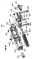
- FIG. 35 is an exploded perspective view of one embodiment of the moveable assembly 3401 of FIG. 34.
- FIG. 36 shows an exploded perspective view of one embodiment of a base rotation assembly 3600 , according to one embodiment of the invention.
- FIG. 37 is an exploded perspective view of a display mounting assembly 3700 , according to one embodiment of the invention.
- FIG. 38 is an exploded, perspective view of a moveable assembly 3800 , according to one embodiment of the invention.
- FIG. 39A is an exploded, perspective view of one embodiment of a spring assembly 3900 , according to one embodiment of the invention, showing various internal component parts associated therewith.
- FIG. 39B is a perspective view of an assembled spring assembly 3900 , according to one embodiment of the invention.
- FIG. 40 is a force diagram illustrating one embodiment of a computer system 4000 that includes a base 4030 attached to one end of a moveable assembly 4040 and a flat panel display device 4050 attached to the other end of the moveable assembly 4040 , in which a display weight 4010 is counterbalanced using a spring force 4020 .
- FIG. 41 is a graph depicting illustrative counter-balance sum of moments for a moveable assembly, according to one embodiment of the invention.
- FIG. 42 is a graph depicting illustrative counter-balance sum of moments with error bars for a moveable assembly, according to one embodiment of the invention.
- FIG. 43A depicts one embodiment of a counterbalance adjustment mechanism in a first position.
- FIG. 43B depicts one embodiment of a counterbalance adjustment mechanism in a second position.
- FIG. 44 is a graph depicting counter-balance with manufacturing error bars after tuning for a moveable assembly, according to one embodiment of the invention.
- FIG. 45 is a graph depicting the pitch counter-balance sum of moments for one embodiment of a moveable assembly.
- FIG. 46 is a cross-sectional view of the moveable assembly 3401 of FIG. 34, showing placement of data, power, and other computer system-related cables therein, according to one embodiment of the invention.
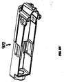
- FIG. 47 is a side view of one embodiment of a computer controlled display system.
- FIG. 48A is a perspective view of one embodiment of a link 4801 of the moveable assembly 4702 shown in FIG. 47.
- FIG. 48B is a cross-sectional side view of link 4801 taken along the line A-A in FIG. 48A.
- FIG. 49 is an exploded perspective view of an embodiment of a link 4901 and a brake assembly 4914 .
- FIG. 50A is a side view of one embodiment of a ball-and-socket assembly 5001 of the moveable assembly 4702 shown in FIG. 47.
- FIG. 50B is a cross-sectional side view of ball-and-socket assembly 5001 taken along the line A-A in FIG. 50A.
- FIG. 51A is a cross-sectional view of an embodiment of an alternative configuration of a bladder 5103 within a ball-and-socket assembly 5100 .
- FIG. 51B is a cross-sectional view of an embodiment of an alternative configuration of a bladder 5113 within a ball-and-socket assembly 5110 .
- FIG. 52A is a side view of one embodiment of a ball-and-socket assembly 5201 of the moveable assembly 4702 shown in FIG. 47.
- FIG. 52B is a cross-sectional side view of ball-and-socket assembly 5201 taken along the line A-A in FIG. 52A.
- FIG. 1E depicts one embodiment of a conventional computer system that may be used with a display device as described herein.
- the computer system 151 interfaces to external systems through a modem or network interface 167 .
- the modem or network interface 167 may be considered part of computer system 151 .
- This interface 167 may be an analog modem, an ISDN modem, a cable modem, an Ethernet interface, a satellite transmission interface (e.g. Direct PC), or other network interface for coupling a digital processing system to other digital systems (e.g. the interface 167 couples computer system 151 to a local computer network or to the internet).
- the computer system 151 includes a processor 153 which may be a conventional processor, such as a Motorola Power PC microprocessor or an Intel Pentium microprocessor.
- Memory 155 is coupled to processor 153 by the bus 157 .
- Memory 155 may be dynamic random access memory (DRAM) and may also include static RAM (SRAM).
- the bus 157 couples the processor 153 to the memory 155 and also to mass memory 163 and to display controller 159 and to the I/O (input/output) controller 165 .
- Display controller 159 controls in the conventional manner a display on the FPDD 161 , which may be a liquid crystal display device or other flat panel display device (e.g.
- the display controller 159 is coupled to the display 161 through a cable 160 , which in one embodiment provides display data and power and control signals between the display 161 and the display controller 159 .
- the input/output devices 169 may include a keyboard, disk drives, printers, a scanner, a digital camera, and other input and output devices, including a mouse or other pointing device.
- the display controller 159 and the I/O controller 165 may be implemented with conventional well-known technology.
- the mass memory 163 is often a magnetic hard disk, an optical disk, or other form of storage for large amounts of data. Some of this data is often written, by a direct memory access process, into memory 155 during the execution of software in the computer system 151 . It will be appreciated that the computer system 151 is one example of many possible computer systems which have different architectures. For example, Macintosh or Wintel systems often have multiple buses, at least one of which may be considered to be a peripheral bus.
- Network computers may also be considered to be a computer system which may be used with the various display devices described herein.
- Network computers may not include a hard disk or other mass storage, and the executable programs are loaded from a network connection (e.g. through network interface 167 ) into the memory 155 for execution by the processor 153 .
- a Web TV system which is well-known in the art, may be considered to be a computer system according to the present invention, but it may not include certain features shown in FIG. 2B, such as certain input/output devices.
- a cell phone, a personal digital assistant, or a digital camera having a suitable display interface (to couple to a display device as described herein) and a processor and memory may also be considered to be a digital processing system or a computer system which may be used with the present invention.
- a typical computer system will usually include at least a processor, a memory, and a bus coupling the memory to the processor. It will also be appreciated that computer system 151 is typically controlled by an operating system software which includes a file management system and a disk operating system.
- certain elements of the computer system 151 e.g. processor 153 , memory 155 , bus 157 , mass memory 163 , display controller 159 , I/O controller 165 , an optical drive (not shown), and possibly also interface 167 ) are housed in a moveable enclosure 242 A which is coupled to the base 242 of the moveable assembly (shown in FIGS. 2A-2D as moveable assembly 200 ).
- the opposite end of the moveable assembly is coupled with a FPDD (e.g. display 240 , which corresponds to display 161 ).
- a cable is disposed within an interior portion of the moveable assembly 200 and couples the display 240 to the display controller 159 , which provides display data to the display 240 through the cable 160 .
- the cable may also provide power and the control signals (if any, such as brightness or contrast signals sent by an input device on the FPDD 240 to the system 151 ) to the FPDD 240 .
- the moveable enclosure 242 A is small enough and light enough to be picked up and moved by a single adult person, and yet is heavy enough to support the FPDD 240 at various different positions without tipping.
- the moveable enclosure 242 A need not be physically attached (e.g. by clamps or adhesive or other fixtures) to a support surface (such as a desk, shelf, counter, or table) because its size, weight, and shape are sufficient to support the moveable assembly 200 and FPDD 240 at various positions without tipping.
- a FPDD 240 may measure approximately 6.0 inches or more, as measured diagonally across its viewing surface from one corner to an opposite corner, and may weigh approximately 1.5 pounds or more.
- the size, shape, and weight of moveable enclosure 242 A should be selected such that no tipping occurs when the moveable assembly 200 is bent approximately ninety degrees from vertical.
- no tipping occurs when a downward user force of approximately 2.0 lbs to approximately 3.0 lbs is applied to FPDD 240 when moveable assembly 200 is bent approximately ninety degrees from vertical.
- the bottom surface area of moveable enclosure 242 A measures in the range of approximately 0.5 square feet to approximately 4.0 square feet.
- the system is designed to support a FPDD 240 weighing in the range of approximately 5.0 lbs to approximately 6.0 lbs, at approximately 25.0 lbs of user force.
- the length of the moveable assembly 200 may range from approximately 7.0 inches to approximately 48.0 inches.
- the base 242 of moveable assembly 200 may be clamped or otherwise fastened to a ground surface or an overhead surface.
- Base 242 of moveable assembly 200 may also be clamped or otherwise fastened to a substantially planar surface (e.g. desktop) or vertical surface (e.g. wall or side of a desk).
- Remote coupling may be accomplished using a wireless system or using extended lengths of power and data cables.
- moveable assembly 200 may be coupled with FPDD 240 , as shown.
- Components of moveable assembly 200 may include: an actuator assembly 202 , a display termination ball 222 ; a friction limit ball 226 ; a base 242 ; and a plurality of cables 234 , including a tension cable, anti-torsion cable, data, microphone, power supply cables, and other cables.
- actuator assembly 202 may be centrally and fixedly coupled with a backside of flat panel display device (FPDD) 240 using any of a number of suitable attachment methods (e.g. bolts, welds, adhesives, etc.) well-known in the art.
- Actuator assembly 202 is provided to reduce the amount of user force needed to collapse the moveable assembly. Typically, a user force of approximately 180 pounds to approximately 400 pounds is required. However, actuator assembly 202 reduces this force to an amount easily provided by an adult user (e.g. approximately 10.0 pounds to approximately 30.0 pounds).
- FIGS. 2A, 2B, 2 C, 2 D, 4 A, and 4 B several of the ball-and-socket components are not shown in order to provide views of the cables which are within the ball-and-socket components.
- Actuator assembly 202 may be wholly contained within a housing of FPDD 240 such that handle 241 may afterwards be coupled with a component of actuator assembly 202 via insertion through an opening in the housing.
- Handle 241 may be formed of a single piece or of multiple pieces of a stiff, durable material such as metal, plastic, or a composite material. Exemplary metals include steel, aluminum, titanium, and alloys thereof.
- a proximal end of handle 241 may be shaped to include (or may be coupled with) a finger support member 260 , which provides a first compression surface. Finger support member 260 may be made of the same or a different material that comprises the remainder of handle 241 , and may take any suitable aesthetic or ergonomic shape, size, or contour.
- a distal end of handle 241 may be pivotably coupled with one or more components of actuator assembly 202 such that handle 241 functions as a lever arm.
- handle 241 is angled away from the backside of FPDD 240 such that the proximal end of handle 241 is positioned near an edge of FPDD 240 . In one embodiment, the edge may be the left-hand edge of FPDD 240 as viewed from the back (e.g. right-hand edge as viewed from the front).
- a tension cable coupled at one end with base 242 and coupled with a component of the actuator assembly 202 at the other, functions to keep the balls 226 and sockets 227 generally aligned.
- the tension cable locks the moveable assembly 200 in a desired viewing position by forcibly pressing balls 226 against friction inserts in sockets 227 .
- Pulling the proximal end of handle 241 towards the backside of FPDD 240 relaxes the taut tension cable such that spring activated plungers in sockets 227 lift balls 226 away from the friction inserts to allow moveable assembly 200 to be manipulated into a desired configuration.
- the desired configuration may be “frozen” or locked into position simply by releasing handle 241 .
- a user may adjust the viewing position of FPDD 240 by grasping the left-hand and right-hand edges of FPDD 240 with both hands.
- the user's palms may rest on portions of the front surface of FPDD 240 , with the fingers of each hand naturally curling behind FPDD 240 to rest on either its backside or on the finger support member 260 .
- the user may relax moveable assembly 200 by compressing the fingers of the right-hand against the first compression surface, which is the finger support member 260 previously described, while simultaneously compressing the palm of the right hand against a second compression surface, which is a portion of the front surface 240 A of FPDD 240 .
- This compressing moves the proximal end of handle 241 from a first tensioned position towards the back of the FPDD 240 , while simultaneously moving the handle's distal end away from the back of FPDD 240 .
- the tensioned cable relaxes and the formerly rigid moveable assembly becomes flexible.
- moveable assembly 200 may adjust the viewing position of FPDD 240 using one or both hands.
- the user may compress handle 241 with one hand, while manipulating moveable assembly 200 with the other.
- a desired viewing position may be locked in place by opening the fingers of the hand compressing the handle to allow the handle 241 to move from a second relaxed position back to the first tensioned position.
- FIG. 2B a back view of moveable assembly 200 is shown.
- display termination ball 222 and actuator assembly 202 are positioned substantially in the center of the back of FPDD 240 in order to provide an axis of rotation substantially near FPDD 240 's center-of-mass.
- display termination ball 222 and actuator assembly 202 may be non-centrally positioned on the back surface of FPDD 240 .
- the outermost edge of handle 241 may be substantially coterminous with an edge of FPDD 240 , or not.
- FIG. 2C there is shown, according to one embodiment of the invention, a plan view of FPDD 240 and moveable assembly 200 .
- the gap 290 between handle 241 and a back surface of FPDD 240 is more clearly shown. In one embodiment, this distance measures approximately 50.0 mm to approximately 70.0 mm.
- Gas 290 represents the distance through which handle 241 moves during a power stroke (e.g. depressing the handle to release the tension holding the FPDD 240 ).
- the gap may measure approximately 50.0 mm to approximately 70.0 mm.
- the size of gap 290 may be determined based on the average measurements of an adult human hand, which average may be calculated from combined measurements of approximately 10 adult male and approximately 10 adult female hands. Optimally, the size of gap 290 should fall within the range of an adult human's maximum gripping power. Additionally, the size of gap 290 and the length of handle 241 should be coordinated to yield a maximum power stroke from a minimal applied user force. In one embodiment, the applied user force is within the range of approximately 10.0 to approximately 45.0lbs. However, future developments in technology may reduce the amount of applied user force to approximately 10.0 pounds or less. It will be appreciated that such developments are to be construed as falling within the scope of the present invention.
- moveable assembly 200 may be positioned in a variety of sculpted, curved, bent, or spiral positions. As evident from the above Figures, the cable path length of the centrally-positioned tension cable remains substantially constant when moveable assembly 200 is bent or curved. However, the path length of data and power supply cables may vary because they pass through cable guides that are located non-centrally within the interior of balls 226 . Accordingly, an additional length of cable slack approximately equal to about 1 ⁇ 3 of the tension cable length may be included within the moveable assembly 200 for the data and power supply cables. In other embodiments, where the FPDD's power supply is self contained or wirelessly broadcast, and/or where the FPDD's data transmissions are wirelessly broadcast, moveable assembly 200 may contain only tension, torsion, and power cables.
- the display surface area 240 A of the FPDD 240 (which is usually most (e.g. more than 75%) of the surface area of the front surface of the FPDD) is substantially larger (e.g. at least 10 times larger) than a cross-sectional area of the moveable assembly 200 (which may be referred to as a neck).
- This cross-sectional area is a cross-section of the moveable assembly taken perpendicularly relative to the length of the moveable assembly (e.g. the cross section obtained at line 2 D- 2 D shown in FIG. 2D).
- This cross-sectional area is typically a small fraction (e.g.
- the display surface area is the surface on which the display data (e.g. a graphical user interface such as the Macintosh OS X or Windows 2000) is displayed to a user of the computer system.
- the display data e.g. a graphical user interface such as the Macintosh OS X or Windows 2000
- FIG. 3 there is shown a diagram of exemplary torques and overturning moments associated with one embodiment of the invention.
- the three components of this embodiment are the base computer system 310 A, the moveable assembly 310 B, and the FPDD 310 C.
- the base computer system 310 A corresponds to the moveable enclosure 242 A, and also includes a base which secures the moveable assembly 310 B to the base computer system 310 A.
- the base computer system 310 A in one embodiment, includes certain elements of the computer system (e.g. referring to FIG.
- a processor 153 is coupled electrically to the FPDD 310 C through a power and data cable (or cables), which provides power to the FPDD 310 C and provides data for display on the FPDD 310 C (and optionally conveys data, such as control signals, from controls on the FPDD 310 C to the computer system in the base computer system 310 A.
- a power and data cable or cables
- such cable or cables
- the moveable assembly 310 B mechanically couples the base computer system 310 A to the FPDD 310 C. In one embodiment, this coupling is through a series of ball-and-socket joints which are held together by a tension cable within the ball-and-socket joints.
- the moveable assembly 310 B is mechanically coupled to the base computer system 310 A at a base end of the moveable assembly 310 B and is mechanically coupled to the FPDD 310 C at a display end of the moveable assembly 310 B.
- base radius (rb) 307 measures approximately 4.72 inches
- a neck bend radius (RN) 303 of the moveable assembly measures approximately 3.00 inches.
- the total length of the moveable assembly measures approximately 15.00 inches
- the weight of the moveable assembly (Wn) 302 measures approximately 1.76 pounds
- the weight of FPDD and actuator mechanism (Wd) 301 measures approximately 5.00 pounds
- the weight of the base (Wb) 304 measures approximately 12.00 pounds.
- the upward force (Fu) 306 at the display needed to overturn the system is calculated to be approximately 9.25 pounds, while the downward force (Fd) 310 needed to overturn is calculated to be approximately 1.22 pounds.
- distance 309 is measured from base center-of-mass to display center-of-mass.
- distance 308 is measured from the base's center-of-mass to the moveable assembly's center-of-mass.
- the base, and the rest of the assembly should not be so heavy that it cannot be easily moved by a single human user (e.g. an adult user).
- the whole assembly should be less than about 45 pounds (lbs) and have a footprint on the surface on which it rests of less than about four (4) square feet.
- the weight and size of the base are designed, as described herein, to counterbalance the weight of the moveable assembly and FPDD 310 C so that the FPDD 310 C can be selectively positioned at many possible positions (X, Y, Z, pitch, yaw, roll), and the whole assembly is still stable (e.g. does not tip or overturn).
- the base computer system there is no need, normally, to require the base computer system to be fixedly attached to the surface on which it rests; no clamps or suction or adhesive are, in a preferred embodiment, normally needed to maintain stability of the entire assembly.
- the FPDD 240 illustratively shown in FIGS. 2A-2D, is a 15 inch LCD panel having a target weight of approximately 4.20 pounds (1.94 kg).
- the 15.0 inch length is a diagonal distance measured from one corner of the viewing area to an opposite corner.
- the weight of the moveable assembly 200 shown in FIGS. 2A-2D is approximately 2.0 pounds (0.907 kg), including the balls, sockets, and cables.
- the overall articulation length (as measured along a longitudinal dimension of the member 200 ) of moveable assembly 200 is approximately 15.5 inches (39.37 cm), and its maximum cantilever distance is approximately 13.5 inches (34.29 cm).
- the moveable assembly 200 provides the ability to move the FPDD in at least three degrees of freedom and preferably six degrees of freedom (X, Y, Z, pitch, yaw, and roll). Another example of a moveable assembly is described in U.S. patent application Ser. No. 10/035,417 entitled “COMPUTER CONTROLLED DISPLAY DEVICE,” filed Nov. 8, 2001, the contents of which are incorporated by reference herein.
- each ball measures approximately 38.00 mm, and the target articulation angle between segments measures ⁇ 14 degrees.
- ⁇ fraction (3/16) ⁇ inch stainless steel aircraft cable having 7 ⁇ 19 construction is used for the tension cable previously described.
- the tension cable may be covered in a nylon jacket to approximately 0.25 inch diameter, and may be equipped with a ball shank ferrule on the actuator mechanism end and also equipped with a stop ferrule on the base end. Because the tension cable is centrally positioned within the interior of the moveable assembly, it will be appreciated that the tension cable path length remains substantially constant. It will also be appreciated that the tension cable is not limited to a particular length, but that the length of the tension cable may vary depending on the length of the moveable assembly. (e.g. in one embodiment, the tension cable may be approximately 398.90 mm long).
- the path length of these cables is not constant, but changes as the moveable assembly is twisted or bent. Accordingly, additional lengths of data, power, and communications cables may be provided to accommodate the path length change. Illustratively, the additional lengths may measure approximately 20% to 30% more than the straight line path length.
- the straight line path length is the path length measured from one end of the moveable assembly to the other when the moveable assembly is in a substantially straight, non-twisted, unbent position.
- each abrasive socket assembly contains two abrasive inserts.
- a first abrasive insert has a base portion containing an internal thread, while the second abrasive insert has a base portion having a corresponding external thread.
- the interior surfaces of the abrasive inserts are concave and may be coated with granular materials such as silica, aluminum oxide, or tungsten carbide.
- the interior surfaces of the abrasive inserts are brazed with tungsten carbide particles having an approximate grain size of about 0.12 mm.
- the friction surface coverage is approximately equivalent to #140 grit.
- travel of the annular plungers is approximately 0.25 mm per interface.
- a spherical glide ring may be inserted within the socket assembly in place of the abrasive insert.
- one or more rims of the abrasive socket assembly may be equipped with an abrasive ring, as described below.
- a lever ratio of the actuator mechanism is approximately 11:1; and the mechanism stroke ranges from approximately 0.0 mm to approximately 0.7 mm, with an operating range of approximately 0.0 mm to approximately 0.5 mm.
- the user stroke range (nominal) is approximately 50.0 mm to approximately 70.0 mm.
- the user force in one embodiment may range from approximately 20.0 to approximately 25.0 pounds. In other embodiments, the user force may be less than approximately 20.0 pounds.
- the creep adjustment range may be approximately 3.0 mm.
- the force adjustment range may be approximately ⁇ 60.0 pounds (e.g. 0.25 inch adjustment @400 pounds/inch).
- the moveable enclosure has a weight in the range of approximately 12.0 pounds to approximately 13.0 pounds, with a footprint diameter of approximately 240.0 mm. It will be appreciated that the base is not limited to one particular size, weight, shape, or appearance. Rather, heavier bases may have smaller footprints, and vice versa.
- the bottom surface of the moveable enclosure may be larger or smaller than the top surface.
- the bottom of the moveable enclosure may also be equipped with a non-slip surface.
- the non-slip surface may be a tacky, spongy, rubber-like material.
- the non-slip surface may be a rubber suction device.
- the non-slip surface may be a magnetic or electromagnetic device.
- the base may be equipped with one or more input devices (e.g. push buttons, touch sensitive buttons, touch sensitive screens, etc.), peripheral ports, or peripheral devices (e.g. DVD and CD-ROM drives, speakers, etc.).
- input devices e.g. push buttons, touch sensitive buttons, touch sensitive screens, etc.
- peripheral ports e.g. DVD and CD-ROM drives, speakers, etc.
- peripheral devices e.g. DVD and CD-ROM drives, speakers, etc.
- one or more components of a computer may be housed within the moveable enclosure.
- the moveable assembly 200 is not limited to supporting a particular load, but that moveable assembly 200 may be designed to accommodate a variety of loads.
- the moment sum at the base socket is calculated, thus:
- an estimated holding torque at the base is approximately 125.0 inches*pounds, with an estimated margin of approximately 1.5.
- FIG. 4A there is shown a cross-sectional top view of a moveable assembly 400 , actuator assembly 400 A, and FPDD 440 , according to one embodiment of the invention.
- Tension cable 490 runs through central portions of balls 426 and terminates at the display end in a ball ferrule 434 , which is coupled with distal end of handle 460 .
- ball ferrule 434 may be coupled with a crank (not shown), which is coupled with handle 460 .
- the distal end of handle 460 is coupled with a strut 409 , which is coupled with a spring or piston assembly 470 .
- the crank, handle 460 , strut 409 , and spring or piston assembly 470 are further described below.
- operation of the actuating mechanism leverages conservation of energy principles to reduce the amount of user force required to relax the tensioned moveable assembly (e.g. neck) 400 .
- tension cable 490 is stretched with an applied force (e.g. tension) of approximately 200.00 to approximately 400.0 pounds.
- This applied force compresses resilient members (e.g. wave springs) 480 and plungers 428 such that balls 426 contact friction inserts 430 and 431 .
- resilient members e.g. wave springs
- plungers 428 such that balls 426 contact friction inserts 430 and 431 .
- the moveable assembly 400 is compressed (e.g. tensioned)
- kinetic stretching energy associated with an applied user force is converted to elastic potential energy, which is stored in the tensioned cable 490 and in the wave springs 480 .
- tension cable 490 and the wave springs 480 are not massless and ideal (e.g. having no internal friction when compressed or stretched), a portion of the kinetic stretching energy is “lost” (e.g. converted to other forms of energy, such as heat); however, the overall mechanical energy associated with the system remains constant.
- the stretched tension cable 490 and the compressed wave springs 480 e.g. resilient members
- the restoring force tends to pull the handle's (or tongue's) distal end upwards, which tends to move the proximal end of handle 460 (or tongue 705 ) downwards, which tends to move a lower end of strut 409 (or 709 in FIG. 7A) laterally against spring/piston assembly 470 (or spring assembly 711 in FIG. 7A).
- moving the actuator from a second state e.g. the distance separating the actuator handle from the back of the FPDD is minimized
- a first state e.g.
- the distance separating the actuator handle from the back of the FPDD is maximized) transfers a portion of the elastic potential energy stored in a compressed spring/piston assembly into elastic potential energy stored in a tensioned tension cable and in a plurality of resilient members. At the same time, the remaining stored elastic potential energy is converted to work done on the user and to kinetic energy of the actuator.
- the spring constant of spring assembly 711 (FIG. 7A) or 811 (FIG. 8) is chosen such that the spring force exerted by spring or piston assembly 470 (or 711 in FIG. 7A) on strut 409 (or on spring shaft 708 and 806 in FIGS. 7A and 8, respectively) equals or slightly exceeds the restoring force exerted by the tensioned cable and wave springs. In this manner, the moveable assembly 400 (FIG. 4A) remains compressed and rigid.
- An illustrative range of spring constants may include: approximately 180.0 lbs/in to approximately 200.0 lbs/in, but preferably approximately 190.0 lbs/in.
- depressing proximal end 451 A of handle 460 moves strut 409 laterally to compress spring/piston assembly 470 . Simultaneously, the distal end of handle 460 moves upwards to relax the tension cable 490 and decompress the wave springs. Depressing proximal end 451 A of handle 460 converts mechanical energy (e.g. that provided by the user depressing the handle 451 ) and potential energy (e.g. that stored in the tensioned cable and compressed wave springs) into kinetic energy as strut 409 moves laterally to compress spring/piston assembly 470 (e.g. 711 in FIG. 7A).
- mechanical energy e.g. that provided by the user depressing the handle 451
- potential energy e.g. that stored in the tensioned cable and compressed wave springs
- This kinetic energy is converted into elastic potential energy, which is stored in the compressed spring/piston assembly 470 .
- releasing proximal end 451 A of handle 451 converts the spring's stored elastic potential energy into kinetic energy as strut 409 moves laterally to depress the distal end of handle 451 .
- This kinetic energy is stored as potential energy in cable 490 is tensioned the wave springs as the moveable assembly is compressed.
- the FPDD in one embodiment, may be moved/re-positioned over at least three (and up to as many as five or six) degrees of freedom from a single actuation (e.g. depression) of the handle (actuator), rather than having to loosen two or more locks in order to obtain the ability to move the FPDD simultaneously in more than one degree of freedom.
- the energy stored in the tensioned cable 490 and in the compressed wave springs (e.g. resilient members) 480 significantly reduces the amount of user force required to compress spring/piston assembly 470 (or spring assembly 711 in FIG. 7A).
- compression of spring/piston assembly 470 (or 711 ) requires an applied user force in the range of approximately 10.0 to approximately 30.0 lbs.
- the amount of applied user force required to compress the spring/piston assembly 470 may be further reduced by modifying the angle at which the distal end of tongue 705 (or handle 751 ) connects with tension cable 709 .
- spring or piston assembly 470 may be one of a number of suitable pre-manufactured metal springs or gas piston assemblies known in the art, so long as the spring or piston assembly 470 exerts a restoring force of approximately 200.0 pounds/inch.
- the exterior dimensions of spring or piston assembly 470 measure approximately 2.0 inches to approximately 2.25 inches long.
- the restoring force exerted by the spring or piston assembly 470 may fall within the range of approximately 180.0 pounds/inch to approximately 400.0 pounds/inch.
- the spring or piston assembly 470 may include a resilient member, which when compressed, exerts a restoring force tending to return the compressed resilient member to its uncompressed state. Examples of resilient members include: metal springs, springs made of composite materials, hydraulic pistons, etc.
- a display termination ball 424 having a substantially planar mating surface connects moveable assembly 400 to FPDD 440 , but any suitable attachment method, such as bolts and/or interlocking grooves, may be used to attach display termination ball to FPDD 440 .
- Anti-torsion cable 491 may be provided to prevent moveable assembly 400 from over-twisting and stretching the data, microphone, and/or the power supply cables.
- the diameter 459 of balls 426 measures approximately 38.00 mm, while the diameter 458 of tension cable 490 measures approximately 6.25 mm.
- the center-to-center distance 457 between balls 426 measures approximately 36.00 mm; and the height of socket assembly 427 may measure approximately 24.00 mm.
- the length 451 of handle 460 measured from a proximal end 461 to a pivot pin 462 measures approximately 169.277 mm.
- the distance 455 measured from the center of tension cable 490 to the center of pivot pin 462 , is approximately 15.830 mm; while the distance 454 , measured from the center of tension cable 490 to a proximal end 463 of spring or piston assembly 470 , is approximately 153.60 mm.
- width 453 of FPDD 440 's exterior casing measures approximately 21.162 mm.
- the power stroke distance 452 measured from proximal end 461 to the front surface of FPDD 440 , is approximately 89.924 mm.
- FIG. 4B there is shown a cross-sectional view of moveable assembly 400 .
- tension cable 490 runs through cable guides in the center of balls 426
- anti-torsion cable 439 runs through cable guides spaced apart from the center of balls 426 .
- balls 426 and sockets 427 may bend approximately ⁇ 14.0 degrees to curve moveable assembly 400 into a desired shape. However, in other embodiments, balls 426 and sockets 427 may bend a greater or lesser amount.
- FIG. 5A there is shown a side view of an assembled moveable assembly 500 , including actuator assembly 502 (but without the FPDD and the base of the moveable assembly and the base computer display).
- the length 551 of moveable assembly as measured from surface 503 of base termination ball 533 to surface 504 of display termination ball 522 , measures approximately 397.00 mm.
- FIGS. 5B and 5C show perspective views of one embodiment of moveable assembly 500 .
- FIGS. 5A-5C show the moveable assembly with all of the ball-and-socket components (and hence the data, tension, power, and anti-torsion cables are concealed).
- FIG. 5D is a sectional view of one embodiment of a moveable assembly 500 showing the internal placement of a tension cable 590 .
- Moveable assembly 500 includes socket assemblies 570 A and 570 B, and a ball 560 having a first hollow cavity 551 and a second hollow cavity 552 separated by a central wall in which are located an annular ring 598 , bore 516 , and bore 510 , each of which extend from one side of the central wall to the other.
- the inside surfaces 598 A and 598 B of annular ring 598 are bowed slightly to taper outwards such that the sliding friction between a tension cable 590 passing through the interior of annular ring 598 is minimized.
- friction socket assembly 570 A includes a first plunger 592 A, a resilient member 594 A, and a second plunger 596 A.
- friction socket assembly 570 B includes a first plunger 592 B, a resilient member 594 B, and a second plunger 596 B.
- FIG. 5E is a cross-sectional view of a portion 560 of a moveable assembly usable with an embodiment of the present invention showing the placement of data, tension, torsion, power, antenna, and other computer system related cables within one or more apertures 508 , 512 , 514 , 504 , 506 , 520 , and 516 of the moveable assembly.
- portion 560 of the moveable assembly is a friction limit ball, having a wall (e.g. brace) containing a plurality of apertures (or bores) centrally located therein.
- Apertures 510 , 516 , and 520 are substantially circular in cross-section, while apertures 508 , 514 , 504 , and 506 are irregularly shaped.
- Anti-torsion cables 512 and 518 extend through apertures 510 and 516 , respectively, while torsion cable 590 extends through aperture 520 .
- one or more of the irregularly shaped apertures may include one or more data, power, antenna, and/or similar computer system-related cables.
- aperture 508 includes an inverter cable 528 and a microphone cable 526 , while aperture 514 contains a Transmission Minimized Differential Signaling (TDMS) cable 524 .
- the inverter cable 528 powers the LCD flat panel display, while the TDMS provides data signals to the flat panel display.
- the TDMS cable is made up of four bundles of three wires each. Two wires within each bundle are twin-axial (e.g. helically twisted) signal wires, and the third wire is a drain wire.
- the twin axial signal wires and drain wires are individually insulated with aluminum-mylar.
- EDID Extended Display Identification Data
- a Low Voltage Differential Signaling (LVDS) cable may be used.
- Low Voltage Differential Signaling is a low noise, low power, low amplitude method for high-speed (gigabits per second) data transmission over copper wire.
- LVDS differs from normal input/output (I/O) in a few ways: Normal digital I/O works with 5 volts as a high (binary 1) and 0 volts as a low (binary 0). When a differential is used, a third option ( ⁇ 5 volts), is added, which provides an extra level with which to encode and results in a higher maximum data transfer rate.
- a higher data transfer rate means fewer wires are required, as in UW (Ultra Wide) and UW-2 ⁇ 3 SCSI hard disks, which use only 68 wires. These devices require a high transfer rate over short distances. Using standard I/O transfer, SCSI hard drives would require a lot more than 68 wires. Low voltage means that the standard 5 volts is replaced by either 3.3 volts or 1.5 volts.
- LVDS uses a dual wire system, running 180 degrees of each other. This enables noise to travel at the same level, which in turn can get filtered more easily and effectively.
- data storage is contingent upon the actual voltage level. Voltage level can be affected by wire length (longer wires increase resistance, which lowers voltage). But with LVDS, data storage is distinguished only by positive and negative voltage values, not the voltage level. Therefore, data can travel over greater lengths of wire while maintaining a clear and consistent data stream.
- tension cable 690 terminates at the actuator assembly end in a ball ferrule 634 .
- Socket assembly 627 may be equipped with a wave spring (e.g. resilient member), plungers, and friction inserts, such that plungers supportably engaging friction limit ball 626 raise ball 626 from and lower ball 626 to a friction insert when the wave spring (e.g. resilient member) is either expanded or compressed.
- wave spring e.g. resilient member
- moveable assembly 600 may have first friction area provided by a sequential series of socket assemblies 627 and a second friction area provided by a sequential series of friction limit sockets 625 , which are not equipped with friction inserts, plungers, or wave springs. Instead, friction limit sockets 625 may be cast or machined out of a single material such as aluminum or stainless steel.
- moveable assembly may be constructed using only friction limit sockets 625 , or using only socket assemblies 627 .
- one or more friction limit sockets 625 may be interspersed between two or more socket assemblies 627 .
- the concave interior contact surfaces of friction limit sockets 625 may be brazed with tungsten carbide to provide an improved friction surface.
- an anti-torsion cable 639 may be provided to limit how much moveable assembly 600 may be twisted.
- Other components of moveable assembly 600 may include a base termination socket 637 , a base termination ball 633 , a tension cable ferrule 635 , a strain relief 638 for the data cables, and ferrules 636 for the anti-torsion cable.
- strain relief 638 is made of rubber or plastic.
- actuator assembly 702 is shown in a first tensioning position.
- actuator assembly includes a tongue 705 , a crank 703 , a strut 709 , a spring shaft 708 , and a spring assembly 711 .
- Tongue 705 may be coupled to tension cable ferrule 734 at one end, and coupled via a shaft 713 to a crank 703 .
- Proximal end 703 A of crank 703 may be angled upwards and coupled with strut 709 , which angles downwards to couple with spring shaft 708 via pivot pin 736 .
- a handle may be coupled with crank 703 to form an angle 752 with the horizontal.
- the distance 753 between a front surface of actuator assembly 702 and a center of ferrule 734 may measure approximately 14.26 mm.
- a distance 751 measured from the center of shaft 713 to the center of pivot pin 736 may measure approximately 59.75 mm.
- the angle 752 at which crank 703 is angled upward from the horizontal may measure approximately 20.4 degrees.
- FIG. 7B there is shown a cross-sectional view of an actuator assembly 702 in a second relaxed position, according to one embodiment of the invention.
- a handle (not shown) coupled with crank 703 has been depressed to flatten crank 703 and strut 709 while raising the distal end of tongue 705 to relax the tensioned cable.
- spring 711 (FIG. 7A) has been compressed a distance 755 , which may measure approximately 15.25 mm in one embodiment of the invention.
- the length 756 of spring assembly 711 (FIG. 7A) may measure approximately 43.18 mm
- the distance 754 separating shaft 713 from pivot pin 736 may measure approximately 69.11 mm.
- the distance 757 separating the center of ball ferrule 734 from a front surface of actuator assembly 702 may increase to approximately 21.70 mm.
- FIG. 8 is an exploded perspective view of one embodiment of an actuator assembly 802 .
- Actuator housing 807 may be made of any suitable durable material (e.g. metal, plastic, etc.) known in the manufacturing and computer arts.
- housing 807 may be machined from a single block of aluminum or stainless steel, or cast from a liquid metal or liquid plastic injected or poured into a mold. It will be appreciated that the exterior and interior contours and protrusions or intrusions of housing 807 may be of any size, shape, or dimension necessary to fit a particular desired application.
- housing 807 is blocked, with rounded edges and corners, while a proximal end is rounded and drilled to contain three screw holes 890 .
- a lip 891 may be formed on the proximal end and bored to allow housing 807 to be bolted to a chassis of a FPDD.
- housing 807 is enclosed on three sides with the fourth side left open to allow insertion of various components and sub-assemblies.
- the sides and blocked end of housing 807 may contain one or more circular or rectangular orifices through which various components (e.g.
- spring shaft cap 808 may be inserted to assemble actuator assembly 802 .
- spring shaft cap 808 covers the end of spring assembly 811 , and may be formed of a plastic or metal using the injection molding or machining processes described above.
- shafts 813 , 814 , and 816 may be formed of a metal such as stainless steel.
- the ends of shafts 813 , 814 , and 816 may be threaded to receive a nut, or equipped with an annular groove to receive a pressure fitted washer (e.g. retaining rings 817 and 821 ).
- Thrust washer 818 may be inserted within housing 807 , at the blocked end, to provide a support surface for die spring 811 .
- Spring shaft 806 may be coupled with die spring 811 , and may be formed of a plastic or metal (e.g. stainless steel) using injection molding or machining processes well-known in the art.
- rounded and narrowed proximal end 806 A of spring shaft 806 may contain an orifice of sufficient size and diameter to receive shaft 813 .
- the outer dimensions of proximal end 806 A may such that the proximal end 806 A slidably fits between a first pair of arms of H-shaped strut 809 .
- the first pair of strut arms contain circular orifices corresponding in dimension and placement to circular orifices in proximal end 806 A and housing 807 , such that shaft 813 may be slid through the aligned orifices to operatively link spring shaft 806 with strut 809 .
- strut 809 may contain a second pair of strut arms that slidably straddle a nubbed portion 803 A of crank 803 , such that shaft 814 , passing through aligned circular orifices in the second pair of strut arms and in housing base 807 , operatively couple shaft 809 with crank 803 .
- crank 803 may be formed of plastic or metal (e.g. stainless steel) using injection molding or machining processes well known in the art. It will be appreciated that crank 803 , like the other components of actuator assembly 802 , is not limited to a particular size, weight, configuration, appearance, or shape. Rather, crank 803 may have any size, shape, appearance, or configuration necessary to fit a particular application. At one end, crank 803 is extruded and narrowed to form nubbed portion 803 A, through which a circular orifice is formed. In one embodiment, a horizontally disposed flat planar surface forming the top of nubbed portion 803 A may cascade down into an open portion between two parallel crank arms, each of which contains an orifice to receive shaft 817 .
- plastic or metal e.g. stainless steel
- tongue 805 is an oblong piece of metal, thick in its central portion and tapering to substantially flat ends. Each end may contain a circular orifice extending through its thickness. Similarly, a circular orifice may be bored through the tongue's central portion from one side to the other. The edges of orifice may be recessed such that nylon washers 805 A may be inserted into the orifice flush with the outer portions of tongue 805 .
- Tongue 805 may be slidably inserted between the arms of crank 803 such that shaft 817 may be inserted through the orifices in housing 807 , the crank arms, and the tongue's central portion, to operatively couple tongue 805 with crank 803 .
- a set screw 819 may be provided to adjust the tilt of tongue 805 .
- termination socket 824 equipped with insert 823 , may be used to couple termination ball 822 with the proximal end of housing 807 .
- a flat base portion of display termination ball 822 that contains screw holes corresponding in number, dimension, and placement to the screw holes in the proximal end of housing 807 may be bolted directly to housing base 807 .
- FIG. 9A is a perspective view of one embodiment of a housing base 907 , which corresponds to housing base 807 .
- FIG. 9B there is shown a side view of the housing base 907 shown in FIG. 9A.
- the height 951 of housing base 907 may be approximately 30.75 mm.
- the diameter of circular orifice 990 may measure approximately 6.05 mm.
- the length 953 of rectangular orifice 991 may measure approximately 23.13 mm.
- a distance 952 measured from the center of circular orifice 990 to a first edge of rectangular orifice 991 , may measure approximately 23.13 mm.
- a distance 954 from the center of circular orifice 990 to the bottom edge of rectangular orifice 991 may measure approximately 10.07 mm.
- the depth 955 of rectangular orifice 991 is approximately 12.63 mm.
- FIG. 9C is a bottom view of the actuator housing 907 .
- the distance 957 from a center of holes 992 to the center of holes 966 measures approximately 142.06 mm.
- Distance 958 measured from the center of holes 993 to the center of holes 966 , is approximately 133.69 mm.
- Distance 959 measured from the center of holes 994 to the center of holes 996 , is approximately 42.05 mm.
- the center-to-center distance 960 of holes 966 is approximately 20.30 mm.
- the center-to-center distance 964 of holes 993 is approximately 23.11 mm.
- the center-to-center distance 956 of holes 992 is approximately 22.22 mm.
- Measurement 965 is approximately 3.18 mm.
- the diameter 967 of hole 996 may measure approximately 14.0 mm.
- Width 961 of housing 907 may measure 30.81 mm.
- FIG. 9D is a sectional end view of housing 907 taken along line A-A in FIG. 9C.
- Measurement 962 in one embodiment, is approximately 18.77 mm.
- FIG. 9E is a sectional end view of housing 902 taken along line B-B in FIG. 9C.
- measurement 963 is approximately 20.40 mm.
- FIG. 10A is a perspective view of one embodiment of crank 1003 , which corresponds to crank 803 .
- Proximal end 1094 of crank 1003 may include arms 1098 , which contain circular orifices 1091 .
- circular orifices 1091 correspond in size and placement to each other.
- crank 1003 may include a nubbed portion 1096 , which corresponds to nubbed portion 803 A.
- Nubbed portion 1096 may include a circular orifice 1092 .
- the top of distal end 1097 may be flat, or equipped with sidewalls to form depression 1095 .
- the each sidewall is equipped with screw holes 1093 .
- FIG. 10B is a top view of the crank 1003 shown in FIG. 10A illustrating placement of holes 1093 .
- the diameter 1058 of holes 1093 is approximately 3.0 mm.
- FIG. 10C is a side view of the crank 1003 shown in FIG. 10A.
- Circular orifices 1091 and 1092 have a diameter 1059 of approximately 8.05 mm.
- the center-to-center distance 1051 of orifices 1091 and 1092 is approximately 41.57 mm.
- FIG. 10D is a bottom view of crank 1003 .
- the length 1052 of crank 1003 is approximately 53.60 mm.
- the width 1055 of crank 1003 measures approximately 19.25 mm.
- width 1053 measures approximately 16.80 mm
- width 1054 measures approximately 10.78 mm.
- Length 1057 measures approximately 20.00
- distance 1056 measures approximately 7.98 mm.
- FIG. 11A is a perspective view of one embodiment of a tongue 1105 , which corresponds to tongue 805 .
- Proximal end 1197 of tongue 1105 contain an concave orifice 1195
- distal end 1196 may contain a bore 1191 extending through the thickness of distal end 1196 .
- a bore 1192 may extend from one side of the tongue's central portion to the other.
- the top central portion of tongue 1105 may be ridged to form convex channel 1194 .
- tongue 1105 is shown upside down from the position shown in FIG. 11A.
- the length 1151 of tongue 1105 may measure approximately 44.69 mm.
- the diameter 1198 of bore 1192 may measure approximately 8.5 mm.
- the interior surface of orifice 1195 may be curved at an angle of approximately 12.70 degrees.
- Distance 1152 may measure approximately 11.08 mm.
- Distance 1154 may measure approximately 7.01 mm.
- Distance 1153 may measure approximately 3.00 mm.
- the center-to-center distance between bore 1192 and orifice 1191 is approximately 15.82 mm.
- distance 1156 is approximately 21.38 mm.
- the diameter of orifice 1191 may measure approximately 6.00 mm.
- FIG. 11D is an end view of one embodiment of tongue 1105 .
- distance 1157 measures approximately 17.88 mm
- width 1158 measures approximately 13.95 mm.
- FIG. 12A is a perspective view of one embodiment of a spring shaft 1206 , which corresponds to spring shaft 906 .
- spring shaft 1206 has a nubbed portion 1298 at one end that flares to a perpendicularly disposed circular flange 1297 A, which terminates in a planar surface 1297 B.
- An orifice 1292 may extend through nubbed portion 1298 .
- a flange 1291 may be disposed on an edge of nubbed portion 1298 .
- Extending from the center of planar surface 1297 B is a barrel 1294 .
- Barrel 1294 is cylindrical and of a diameter smaller than the diameter of circular flange portion 1297 A.
- barrel 1294 may contain evenly spaced rectangular orifices 1293 .
- Barrel 1294 terminates in a planar surface 1294 B. Extending from the center of planar surface 1294 B is a second barrel 1295 of smaller diameter than the first, which terminates in knobbed ferrule 1296 .
- FIG. 12B is a side view of one embodiment of the spring shaft 1206 shown in FIG. 12A.
- the distance 1257 from the center of orifice 1292 to the edge of planar surface 1297 B is approximately 10.00 mm.
- FIG. 12C is a cross-sectional side view of spring shaft 1206 taken along the line A-A in FIG. 12B.
- Distance 1254 measures approximately 7.12 mm.
- Distance 1255 measured from the center of orifice 1292 to the edge of ferrule 1296 , is approximately 46.99 mm.
- the diameter 1253 of the circular flange portion 1297 measures approximately 19.00 mm.
- the diameter of ferrule 1296 measures approximately 5.00 mm at its widest point.
- the diameter of barrel 1294 may measure approximately 9.52 mm.
- FIG. 12D is an end view of spring shaft 1206 .
- the thickness 1256 of flange 1291 may measure approximately 3.00 mm.
- FIG. 13A is a perspective view of one embodiment of strut 1303 , which corresponds to strut 903 .
- strut 1303 is H-shaped.
- One pair of arms 1396 may curve downwards as shown, while a second pair of arms 1395 may be straight.
- Arms 1396 may contain orifices 1394 extending through each individual arm. Similar orifices 1393 may extend through the each of arms 1395 . In one embodiment, the outside edges of orifices 1393 may be flared to produce annular rings 1397 .
- Disposed between arms 1396 is a first channel 1391 .
- Disposed between arms 1395 is a second channel 1392 .
- FIG. 13B is a plan view of strut 1303 shown in FIG. 13A.
- Length 1356 of strut 1303 may be approximately 36.59 mm.
- the width 1359 of strut 1303 as measured from the outer edges of annular rings 1397 may be approximately 17.00 mm.
- the width 1358 of the second channel may measure approximately 8.50 mm.
- the width 1357 of the first channel may measure 9.58 mm.
- FIG. 13C is a cross-sectional side view of strut 1303 , taken along the line A-A in FIG. 13B.
- the horizontal center-to-center distance 1351 between orifices 1394 and 1393 is approximately 27.54 mm.
- Distance 1352 measures approximately 7.63 mm.
- Distance 1353 measures approximately 8.03 mm.
- the vertical center-to-center distance between orifices 1394 and 1393 is approximately 4.03 mm.
- FIG. 13D is an end view of strut 1303 .
- the width 1360 of strut 1303 measures approximately 17.43 mm.
- FIG. 14A is a perspective view of one embodiment of a shaft 1416 .
- Shaft 1416 is generally cylindrical, and may be either solid or hollow.
- Shaft 1416 includes a barrel portion 1493 , and an annular channel 1491 disposed near one end of shaft 1416 , and an annular channel 1492 disposed near the opposite end of shaft 1416 .
- a retaining ring fits within annular channel 1492 to secure shaft 1416 in position.
- FIG. 14B is a side view of shaft 1416 showing the various measurements thereof.
- the length 1451 of barrel portion 1493 measured from the interior edges of annular channels 1491 and 1492 , is approximately 17.52 mm.
- length 1451 may measure approximately 25.12 mm or approximately 24.92 mm.
- the outer diameter 1452 of shaft 1416 may measure approximately 4.0 mm.
- FIG. 15A is a perspective view of one embodiment of a display termination socket 1524 .
- socket 1524 is a hollow, annular ring.
- a first annular lip 1592 may be disposed within one end of socket 1524 , and an annular lip 1591 may be disposed inside the socket 1524 near the other end.
- Socket 1524 is used to couple a display termination ball (not shown) with the actuator assembly previously described.
- FIG. 15B is a cross-sectional side view of socket 1524 taken along the line A-A in FIG. 15C, which is a top view of socket 1524 .
- Distance 1551 measures approximately 17.50 mm
- radius 1553 measures approximately 19.00 mm.
- the interior diameter 1552 of socket 1524 may measure approximately 34.50 mm.
- FIG. 16 is a side view of one embodiment of a tension cable 1634 .
- Tension cable 1634 includes a ball ferrule 1654 on one end. The other end may be provided with a compression-fit ferrule (not shown) during assembly of the moveable assembly, as previously described.
- a plastic or nylon sleeve 1656 is centrally disposed about cable 1634 .
- the distance 1651 measured from the center of ball ferrule 1654 to a first end of sleeve 1656 , is approximately 398.90 mm.
- Approximately a 12.00 mm length 1655 of exposed cable 1634 may extend past the first end of nylon sleeve 1656 .
- a distance 1653 measured from a second end of nylon sleeve 1656 to the center of ball ferrule 1654 , is approximately 12.00 mm.
- the diameter of ball ferrule 1654 may measure approximately 11.18 mm.
- FIG. 17A is a perspective view of one embodiment of a friction limit socket 1725 .
- Socket 1725 may be formed of a metal (e.g. stainless steel or aluminum), and may include a first portion 1793 A, a second portion 1793 B, and an annular ring (or channel) 1791 disposed between the first and second portions.
- Friction limit socket 1725 is static, meaning that first portion 1793 A and second portion 1793 B are not moveable.
- a concave surface 1792 A may be formed within first portion 1793 A to receive a friction limit ball (not shown).
- friction limit socket 1725 including concave surfaces 1792 A and 1792 B (FIG. 17C), is formed of a single piece of stainless steel.
- concave surfaces 1792 A and 1792 B separate pieces, which may be threaded together at their base portions to form socket 1725 .
- concave surfaces 1792 A and 1792 B may be coated with a high friction material such as tungsten-carbide or aluminum oxide.
- concave surfaces 1792 A and 1792 B may be left uncoated.
- FIG. 17B is a plan view of friction limit socket 1725 .
- FIG. 17C is a cross-sectional side view of socket 1725 taken along the line A-A in FIG. 17B and showing interior concave surfaces 1792 A and 1792 B.
- Distance 1753 measures approximately 36.00 mm.
- Distance 1754 measures approximately 21.50 mm.
- a first radius 1752 measures approximately 20.00 mm, while a second radius 1751 measures approximately 19.10 mm to form an annular lip about the outer edges of portions 1793 A and 1793 B.
- FIG. 18A is a perspective view of one embodiment of a friction limit ball 1826 .
- Friction limit ball 1826 includes a cosmetic middle portion 1891 ; a first annular friction ring 1892 A disposed on a first end of friction limit ball 1826 ; a second annular friction ring 1892 B disposed on a second end of friction limit ball 1826 ; and a cable guide insert 1893 centrally located within a bore 1896 running through friction limit ball 1826 from one side to the other.
- Friction limit ball is formed of a metal (e.g. stainless steel or aluminum).
- annular friction rings 1892 A and 1892 B are manufactured independently of friction limit ball 1826 and are adhered to friction limit ball 1826 using adhesives well-known in the art.
- annular friction rings 1892 A and 1892 B, cable guide insert 1893 , and friction limit ball 1826 are machined from a single block of aluminum.
- annular friction rings 1892 A and 1892 B are coated with a high friction material such as tungsten-carbide to provide a high friction surface as previously described.
- annular friction rings 1892 A and 1892 B may be left uncoated.
- the annular friction rings not only contact concave surfaces 1792 A and 1792 B when moveable assembly 200 is tensioned, but also serve to limit the friction limit ball's 1826 axis of rotation when moveable assembly 200 is relaxed.
- friction limit ball 1826 may be tilted within socket 1725 until one of the friction limit rings contacts the inner lip of portion 1793 A or 1793 B.
- the axis of rotation is approximately in the range of approximately 10.0 to approximately 25.0 degrees. In other embodiments, the axis of rotation may be greater or lesser than the range illustratively given above.
- FIG. 18B is a plan view of friction limit ball 1826 .
- Cable guide insert 1893 may include four perpendicular cross members. Two holes 1895 A and 1895 B may be centrally disposed in two of the cross members, with the center of each hole located a distance 1861 or 1862 , respectively, from the center of friction limit ball 1826 . In one embodiment, holes 1895 A and 1895 B house an anti-torsion cable. Additionally, a central tension cable bore 1894 may be formed in the center of cable guide insert 1893 to house a tension cable. In one embodiment, distances 1861 and 1862 each measure approximately 8.00 mm.
- FIG. 18C is a cross-sectional side view of a friction limit ball 1826 taken along the line A-A in FIG. 18B.
- the thickness 1851 of friction limit ball is approximately 30.00 mm.
- the outer diameter 1854 of friction limit ball 1826 may be approximately 38.00 mm.
- Distances 1855 and 1856 measured from a vertical line extending though the center of friction limit ball 1826 to the edge of annular friction rings 1892 A and 1892 B, each measure approximately 11.03 mm.
- the radius 1857 is equivalent to the radius 1858 and measures approximately 35.5 degrees.
- the diameter 1852 of a first bore is approximately 23.00 mm.
- the diameter 1853 of a tension cable bore is approximately 6.80 mm.
- FIG. 19A is a perspective view of one embodiment of an abrasive socket assembly 1927 .
- a first plunger 1928 A slidably fits around first friction insert 1930 , which is coupled with a second friction insert 1931 , which slidably fits within a second plunger 1928 B.
- the plungers and friction inserts may be made of a metal (e.g. stainless steel or aluminum).
- Wave spring 1932 is disposed between the first and second plungers to space the plungers apart when moveable assembly 200 is relaxed.
- plungers 1928 A and 1928 B When thrust apart by wave spring (resilient member) 1932 , plungers 1928 A and 1928 B lift friction limit balls 1826 out of contact with friction inserts 1930 and 1931 , thus allowing friction limit balls 1826 to rotate freely within plungers 1928 A and 1928 B.
- base portions of friction inserts 1930 and 1931 are threaded such that the friction inserts may be screwed together to assemble abrasive socket assembly 1927 .
- the concave inner surfaces of friction inserts 1930 and 1931 may be coated with an abrasive material such as tungsten carbide, aluminum oxide, or other abrasive material, as previously described, to provide a high friction support surface.
- abrasive socket assemblies 1927 are used in the bottom one-half to one-third portion of moveable assembly 200
- friction limit sockets 1725 are used in the upper one-half to two-thirds of moveable assembly 200 .
- moveable assembly 200 is equipped with at least two zones of friction: a high friction zone located near the base of moveable assembly 200 , where the most torque occurs; and a low friction zone located towards the display end of moveable assembly 200 .
- abrasive socket assemblies 1927 and friction limit sockets 1725 may be alternated throughout the length of moveable assembly 200 .
- FIG. 19B is a perspective view of a first friction insert 1930 having a concave interior surface designed to mate with an annular friction ring of a friction limit ball.
- Base portion 1992 may be threaded to mate with a base portion of a corresponding second friction insert.
- FIG. 19C is a cross-sectional side view of the friction insert 1930 of FIG. 19B.
- Distance 1952 measures approximately 15.25 mm
- distance 1953 measures approximately 5.00 mm.
- the outer diameter 1955 of the base portion measures approximately 30.25 mm
- the outer diameter of first friction insert 1930 measures approximately 35.50 mm.
- the interior 1954 of the base portion of first friction insert 1930 may be internally threaded.
- Second friction insert 1931 (not shown) has corresponding measurements, except that the base portion of second friction insert 1931 may be externally threaded.
- FIG. 19D is a top view of first friction insert 1930 , showing orifice 1991 bored through the base portion of first friction insert 1930 to allow passage therethough of data, torsion, tension, power, and other computer system-related cables.
- FIG. 19E is a side view of first friction insert 1930 , showing base portion 1992 .
- FIG. 19F is a bottom view of first friction insert 1930 .
- FIG. 19G is a perspective view of a second friction insert 1931 , showing a second, externally-threaded base portion 1993 .
- FIG. 19H is a cross-sectional side view of second friction insert 1931 taken along the line A-A in FIG. 19K.
- Distance 1961 measures approximately 15.25 mm.
- Distance 1963 measures approximately 5.00 mm.
- Outer diameter 1964 of the base portion measures approximately 30.25 mm, and outer diameter 1965 of second friction insert 1931 measures approximately 35.50 mm.
- the exterior 1966 of the base portion may be threaded such that the base portions of second friction insert 1931 and first friction insert 1930 screw into each other.
- FIG. 19I is a plan view of second friction insert 1931 showing an orifice 1994 bored through the base portion of the insert to allow for the passage therethrough of data, power, anti-torsion, tension, power, and other computer system-related cables.
- FIG. 19J is a side view of the second friction insert 1931 showing base portion 1993 .
- FIG. 19K is a bottom view of second friction insert 1931 .
- FIG. 20 is a cross-sectional side view of an assembled abrasive socket assembly 2027 , which corresponds to abrasive socket assembly 1927 , according to one embodiment of the invention.
- plunger 2093 corresponds to plunger 1928 A
- plunger 2094 corresponds to plunger 1928 B.
- plunger 2093 has been fashioned to slidably fit around plunger 2094 so as to present a more desirable aesthetic external appearance.
- Plungers 2093 and 2094 may be made of plastic or a metal (e.g. aluminum or stainless steel), and colored as desired.
- Annular wave spring 2032 corresponding to wave spring (e.g.
- Friction insert 2030 corresponding to friction insert 1930 , is screwed into friction insert 2031 , which corresponds to friction insert 1931 , at thread interface 2092 .
- the friction inserts may be glued together at glue area 2091 using adhesives well-known in the art.
- FIG. 21A is a perspective view of one embodiment of a base termination ball 2133 .
- Base termination ball 2133 is similar to friction limit ball 1826 , except that one end of base termination ball 2133 includes a flattened base portion 2192 to couple moveable assembly to a moveable base structure.
- An annular friction ring 2191 is formed or attached at one end of base termination ball 2133 .
- Flattened base portion 2192 may be coupled with a moveable base structure using screw holes 2197 , 2195 C, 2195 A, and 2195 B.
- flattened base portion 2192 may include a central tension cable guide orifice 2194 , a pair of anti-torsion cable orifices 2193 , and a plurality of cable guide orifices 2196 .
- base termination ball 2133 may be made of metal (e.g. stainless steel or aluminum).
- FIG. 21B is a bottom view of base termination ball 2133 .
- the horizontal center-to-center distance 2151 between orifice 2195 C and 2195 B is approximately 24.00 mm.
- Orifice 2195 B is located a distance 2152 of approximately 12.00 mm from a vertical line running through the center of tension cable guide orifice 2194 , and located a distance 2154 of approximately 7.50 mm from a horizontal line running through the center of tension cable guide orifice 2194 .
- the vertical center-to-center distance 2155 between orifice 2195 B and 2195 A is approximately 15.00 mm. In one embodiment, distance 2156 measures approximately 14.50 mm.
- FIG. 21C is a cross-sectional side view of base termination ball 2133 taken along the line A-A in FIG. 21B.
- Outer diameter 2157 of the flattened base portion measures approximately 34.45 mm.
- Distance 2158 measures approximately 13.50 mm.
- Arc 2159 measures approximately 36.0 degrees.
- Distance 2162 measures approximately 23.00 mm.
- the diameter 2161 of the tension cable guide orifice measures approximately 6.80 mm.
- Distance 2160 measures approximately 11.17 mm.
- the outer diameter 2164 of base termination ball 2133 measures approximately 38.00 mm.
- FIGS. 22A, 22B, and 22 C show examples of such moveable assemblies which incorporate aspects of the present invention.
- Examples of these aspects include a base computer system which is moveable by a person and is not physically attached to a surface (except through the weight of the system due to gravity), or the use of a single actuator on the back of the FPDD in order to control the repositioning of the FPDD without requiring the actuation or loosening of multiple locks for the various joints, or a data cable which is housed within the structure of the moveable assembly.
- FIG. 22A shows an example of a moveable assembly 2202 which is coupled to an FPDD 2203 at one end of the moveable assembly and is coupled to a base computer system 2201 at another end of the moveable assembly 2202 .
- the base computer system 2201 is similar to the base computer system 242 A. It includes many of the typical components of a computer system and has been designed in both size and weight to adequately and stably support the FPDD at a variety of different positions.
- the base computer system 2201 is designed with sufficient weight such that, without physically attaching the base computer system 2201 (except through gravity) to the surface 2204 , the base computer system 2201 will allow the FPDD 2203 to be extended out beyond the edge of the computer system 2201 as shown in FIG.
- the entire system 2200 allows the FPDD 2203 to be positioned at any one of a multitude of locations in which the FPDD 2203 can be positioned given the extent of reach provided by the moveable assembly 2202 .
- the moveable assembly 2202 includes a post (e.g. arm member) 2205 , a post 2206 , and a post 2207 which are coupled to each other through joints 2210 and 2209 as shown in FIG. 22A.
- the post 2205 is coupled to the base computer system 2201 through the rotatable joint 2208 which allows the post 2205 to rotate as shown by arrow 2216 around the joint 2208 .
- the joint 2209 allows post 2206 to rotate relative to post 2205 , allowing an angular displacement along the arrow 2214 as shown in FIG. 22A.
- the angle between post 2206 and 2207 may be varied as these two posts are moved through the joint 2210 , allowing motion along the arrow 2215 .
- Both joints 2209 and 2210 include locking mechanisms 2212 and 2213 respectively, allowing the relative angular position between the corresponding posts to be fixed.
- a single locking actuation control may be disposed on the surface of the FPDD 2203 in a manner which is similar to the handle 241 described above.
- this single actuation control may be an electromagnetic control which loosens or tightens the joints electromagnetically under the control of the single actuation switch disposed on the FPDD 2203 .
- the post 2207 terminates in a gimbal joint 2211 which is coupled to the FPDD to allow movement of the FPDD relative to the post 2207 .
- data and power cables 2220 and 2221 are disposed within the interior portions of the posts 2205 , 2206 and 2207 .
- these cables are concealed within the interior of the posts, which represent another form of a moveable assembly for supporting an FPDD. It will be appreciated that other computer system-related cables may be housed within the interior portions of posts 2205 , 2206 , and 2207 .
- FIG. 22B shows another example of a moveable assembly 2233 in a system 2233 which includes a base computer system 2232 and an FPDD 2248 .
- the entire system 2233 rests, through gravity, on the surface 2239 without being physically attached to the surface except through gravity.
- the bottom of the computer system 2232 may include a non-slip surface, such as rubber feet.
- the weight and size of the base computer system 2232 is designed according to the teachings of the present invention to allow the support of the FPDD 2248 in a variety of selectable positions of the FPDD 2248 , there is no need for the base computer system 2232 to be physically attached to the surface 2239 through the use of clamps or glues or bolts or screws, etc.
- the computer system 2232 has a weight and size which allows a single human user to be able to move the computer system without assistance from another person or from a mechanical assistance.
- the base computer system 2232 is attached to post 2235 through a rotatable joint 2238 , which allows the post 2235 to rotate around the base computer system along the arrow 2243 .
- Post 2236 is coupled to post 2235 through the joint 2239 , which will be locked through the locking mechanism 2240 .
- the joint 2239 allows the angle between post 2235 and 2236 to be varied by moving the post 2236 along the arrow 2241 .
- Posts 2235 and 2236 in the embodiment shown in FIG. 22B, include power and data cables 2270 and 2249 , respectively, which are disposed within these posts and thereby concealed by these posts.
- a single actuating device or switch 2250 may optionally be located on the FPDD 2248 to allow for the release of one or more lockable joints in order to allow the selectable positioning or repositioning of the FPDD.
- FIG. 22C shows another example of a moveable assembly 2264 in a system 2260 which includes the moveable assembly as well as an FPDD 2263 and a base computer system 2261 which rests on a surface 2262 , which may be a desk surface.
- the base computer system 2261 is typically designed to have a weight and size such that it will support the selectable positioning and repositioning of the FPDD 2263 over a large range of movement of the FPDD 2263 .
- the moveable assembly 2264 includes three posts, 2267 , 2268 and 2269 , and also includes three joints 2271 , 2272 and 2273 , and also includes two counterweights 2277 and 2278 .
- the moveable assembly 2264 also includes a gimbal joint 2274 which couples the post 2269 to the FPDD 2263 .
- An optional single actuator control 2280 may be disposed on the FPDD 2263 in order to unlock or lock one or more of the joints.
- the embodiment shown in FIG. 22C may also optionally include the use of power and data cables, which are disposed within the posts 2267 , 2268 , and 2269 .
- the computer controlled display system 2300 includes: a flat panel display device 2301 having a display surface 2302 and an input 2303 for receiving display data to be displayed on the display surface 2302 .
- a moveable assembly 2304 is mechanically coupled to the flat panel display 2301 .
- the moveable assembly 2304 has a cross-sectional area, which is substantially less than an area of the display surface 2302 .
- Moveable assembly 2304 is moveable when handle 2307 is depressed, to allow the flat panel display device 2301 to be selectively positioned in space relative to a user of the computer controlled display system 2300 .
- a base e.g.
- the moveable enclosure 2305 is coupled mechanically to the moveable assembly 2304 and to the flat panel display device 2301 through the moveable assembly 2304 .
- the base houses concealed computer components, which include, but are not limited to: a microprocessor, a memory, a bus, an I/O (input/output) controller, optical drive, network interface, and I/O port.
- the microprocessor is coupled to the input of the flat panel display 2301 .
- the cross-sectional area is defined by a cross-section taken perpendicularly to a longitudinal dimension of the moveable assembly 2304 .
- the moveable assembly 2304 is moveable such that the FPDD 2301 has at least three degrees of movement.
- the overall weight of the entire system is less than about 45.0 lbs and a footprint size of the base 2305 is less than an area of about 4.0 square feet.
- an actuator 2306 is attached to the flat panel display 2301 and coupled to a force generator (e.g. spring/piston assembly) which maintains the moveable assembly 2304 in a rigid mode when the actuator (handle) 2306 is in a first state, and which allows the moveable assembly 2304 to be moveable when the actuator (handle) 2306 is in a second state.
- a force generator e.g. spring/piston assembly
- the actuator 2306 through a single actuation, allows simultaneous positioning of the flat panel display 2301 and moveable assembly 2304 in multiple degrees of freedom.
- a data cable (not shown) is coupled to the input of the flat panel display 2301 at a first end, and coupled to a display controller (not shown) housed within the base 2305 , the cable being disposed (and/or concealed) within the moveable assembly 2304 .
- an anti-torsion cable (not shown) is coupled to (and preferably within) the moveable assembly 2304 to restrain the flat panel display (and the moveable assembly 2304 ) from being rotated beyond a pre-determined amount.
- the longitudinal dimension of the moveable assembly 2304 extends from the flat panel display 2301 to the base 2305 , and a weight of the system 2300 is less than about 25.0lbs and a footprint size of the base 2305 is less than an area of about 500.0 square centimeters.
- the base 2305 is not fixedly secured to a supporting surface under the base 2305 .
- FIG. 23B is a perspective view of another embodiment of a computer controlled display device including a FPDD 2301 coupled with a moveable assembly 2304 , which is coupled with a base 2305 .
- actuator assembly 2306 is mounted on or contained within the rear housing 2308 of FPDD 2301 .
- the internal structure of FPDD is strengthened to withstand the compressive user forces applied simultaneously to handle 2306 A and the front surface of FPDD 2301 .
- the external shape of base 2305 in one embodiment, forms a toroid, as shown, and includes an inner metal Faraday cage, concealed by a layer of plastic, which repels external Electromagnetic Frequencies (EMF) that may interfere with operation of the computer components concealed within the base 2305 .
- EMF Electromagnetic Frequencies
- the Faraday cage also contains internal EMF generated by the concealed computer components.
- the concealed metal Faraday cage like the outer plastic layer, is manufactured in two pieces, a top portion and a bottom portion, which when fitted together form a toroid.
- the Faraday cage may be made of zinc, zinc alloys, or other suitable metals known in the art.
- the base 2305 and its internal components weighs approximately 13.0 pounds, while the FPDD 2301 weighs approximately 4.5 pounds.
- the moveable assembly 2304 , base 2305 , and FPDD 2301 are manufactured such that a user can safely lift computer system 2300 using moveable assembly 2304 as a carrying handle. Additionally, the system is manufactured such that a user can safely hoist the entire system simply by grasping the FPDD 2301 and lifting.
- safely lift and “safely hoist” mean that the various system components suffer minimal or no external or internal damage as a result of the user's lifting actions.
- the exterior plastic housing of base 2305 may be formed of two parts, a top portion and a bottom portion 2305 A, which, when fitted together, form a toroid.
- the bottom portion 2305 A may contain a plurality of peripheral ports and/or computer system-related controls 2310 .
- Such ports and controls illustratively include, but are not limited to one or more of: a Firewire port, an Ethernet port, a modem jack, a power button, a reset button, a USB port, an infrared port, and similar computer system-related ports and controls.
- FIG. 23C is a side view of the computer system 2300 shown in FIGS. 23A and 23B, according to one embodiment of the invention.
- System 2300 includes a FPDD 2301 having an actuator assembly 2306 attached thereto; a moveable assembly 2304 attached to the actuator assembly 2306 , and a base 2305 attached to the moveable assembly 2304 .
- moveable assembly 2304 is a snake-like ball-and-socket assembly; however, it will be appreciated that other types of assemblies may also be used.
- an optical drive (e.g. CD and/or DVD) aperture 2312 is provided in the top portion of base 2305 .
- Aperture 2312 in one embodiment, includes an electronically activated fold-down door and an electronically activated slide-out optical disk tray. In one embodiment, pressing a button on a keyboard coupled with base 2305 activates the fold-down door and slide-out tray.
- FIG. 23D is a rear-view of the computer system 2300 shown in FIGS. 23A-23C, according to one embodiment of the invention.
- system 2300 includes FPDD 2301 , actuator assembly 2306 , moveable assembly 2304 , and base 2305 , which includes a plurality of peripheral ports and computer system-related controls 2310 , as described above.
- FIG. 23E is a front view of the computer system 2300 of FIGS. 23A-23D, according to one embodiment of the invention, and showing FPDD 2301 , viewing surface 2302 , and base 2305 .
- FIG. 23F is another side view of the computer system 2300 of FIGS. 23A-23E, according to one embodiment of the invention, and showing FPDD 2301 , actuator assembly 2306 , moveable assembly 2304 , and base 2305 .
- a moveable assembly 2302 similar to that previously described with reference to FIGS. 4A and 4B is shown coupled with a flat panel display 2310 , which, in one embodiment, includes a housing 2301 attached to a portion of the flat panel display obverse from a viewing portion 2311 of the flat panel display 2310 .
- Housing 2301 is coupled to moveable assembly 2302 using at least one screw 2331 or a plurality of screws 2331 .
- various components of actuator assembly 2300 A include a tongue 2305 , a crank 2303 , a strut 2309 , a spring guide 2308 , and a spring 2370 .
- Tongue 2305 has a distal end 2306 B coupled with a ball ferrule 2335 , which is attached to a tension cable 2334 extending through an interior portion of moveable assembly 2302 .
- a proximal end 2306 A of tongue 2305 is coupled with a distal end 2303 B of crank 2303 .
- the proximal end 2303 A of crank 2303 is operatively coupled with the distal end of a strut 2309 , and a proximal end of strut of 2309 is coupled with a distal end 2308 B of spring guide 2308 , which is inserted within the interior of a spring 2370 .
- spring guide 2308 progressively narrows or tapers downwards from the distal end 2308 B to its proximal end 2308 A, which includes a bushing 2350 , which helps reduce friction and wear as proximal end 2308 A slides within channel 2307 .
- tongue 2305 may include at its proximal end 2306 A a channel extending therethrough into which a set screw or other screwlike mechanism 2305 A is placed. Set screw 2305 A may be adjusted to vary the angle at which the distal end of tongue 2305 contacts the ball ferrule of tension cable 2334 .
- a handle 2360 having a distal end 2360 B and a proximal end 2360 A may be operatively coupled with the actuator assembly 2300 .
- distal end 2360 B of handle 2360 is coupled with a top portion of crank 2303 using a set screw 2332 .
- proximal end 2360 B is fashioned into an ergonomic design.
- the actuator assembly 2300 shown in FIG. 23G differs from the actuator assembly 400 , shown in FIG. 4A.
- the distal end of handle 460 was coupled with ball ferrule 434 attached to tension cable 490
- the distal end 2360 B of handle 2360 is coupled crank 2303 , which is operatively coupled with tongue 2305 .
- Tongue 2305 is coupled with the ball ferrule 2335 attached to tension cable 2334 .
- the angle at which tongue 2305 contacts ball ferrule 2335 is greater than the angle at which distal end of handle 460 contacts ball ferrule 434 .
- the changed tongue angle provides the tensioning mechanism (e.g. actuator assembly 2300 A), with increased mechanical advantage as the cable 2334 becomes tighter, which reduces the amount of user force required to relax moveable assembly 2302 .
- an angle measured between a first horizontal line drawn through the center of pivot 2370 and a second oblique line extending from the center of pivot 2370 , centrally through the distal end 2306 B of tongue 2305 measures in the range of approximately 40.0 degrees to approximately 85.0 degrees, preferably approximately 70.0 degrees.
- FIG. 24A is a perspective view of a tongue 2400 , which corresponds to tongue 2305 in FIG. 23G.
- tongue 2400 includes a distal end 2497 and a proximal end 2496 .
- a cylindrical bore 2492 extends through the middle portion of tongue 2400 in one embodiment.
- the distal end 2497 of tongue 2400 includes a bore (or cavity) 2495 extending from a top surface of tongue 2400 downward towards a bottom surface of tongue 2400 .
- proximal end 2496 of tongue 2400 there is included a cylindrical bore 2491 extending from a top surface of tongue 2400 to a bottom surface of tongue 2400 .
- tongue 2400 has an overall length 2451 of approximately 41.47 mm.
- a distance 2452 as measured from the center point of bore 2491 to a center point of horizontal bore 2492 measures approximately 15.83 mm.
- a center-to-center distance 2454 from bore 2492 to bore 2495 measures approximately 13.64 mm.
- a distance 2453 from a bottom surface of distal end 2497 to a horizontal line 2499 extending through the midpoint of bore 2492 measures approximately 14.63 mm.
- the radius 2455 of bore 2492 measures in the range of approximately 11.100 mm to approximately 11.125 mm.
- an interior beveled portion of cavity 2495 has a radius of approximately 11.40 mm plus or minus 0.25 mm.
- tongue 2400 in one embodiment, has a depth (or height) 2459 of approximately 22.63 mm as measured from a top surface 2400 A to a bottom surface 2400 B of tongue 2400 .
- FIG. 24C shows a top view of tongue 2400 according to one embodiment of the invention.
- tongue 2400 has a width 2456 of approximately 11.15 mm minus 0.15 mm. Width of 2456 is measured from a first side 2492 A to a second side 2492 B of bore 2492 extending through a mid portion of tongue 2400 .
- a bottom portion of cavity 2495 is substantially elliptical in shape and has a width 2457 of approximately 6.97 mm.
- a width 2458 of distal end 2497 as measured from a first side 2497 A to a second side 2497 B measures in one embodiment, approximately 13.50 mm.
- FIG. 25A there is shown a perspective view of a glide ring 2500 , which in one embodiment is inserted within a friction socket plunger to preserve the cosmetic finish of the balls.
- glide ring 2500 is substantially spherical in shape having a base portion 2505 which in one embodiment is an annular ring attached to a bottom surface of glide ring 2500 .
- glide ring 2500 has a first diameter 2501 which is larger than a second diameter 2502 , wherein the interior and exterior surfaces of glide ring 2500 curvingly taper from the first diameter 2501 toward the second diameter 2502 .
- the upper sidewall portions of glide ring 2500 may include a plurality of slots 2503 extending downward from a top surface of glide ring 2500 towards the second diameter 2502 .
- a plurality of pegged feet 2504 may be attached to the outer bottom portion of glide ring 2500 . These pegged feet 2504 may be used to hold glide ring securely within an abrasive socket plunger (not shown) by inserting one or more of feet 2504 within a corresponding plurality of holes positioned within an abrasive socket plunger (not shown).
- FIG. 25B is a bottom view of glide ring 2500 , shown in FIG. 25A.
- an angle as measured from a line 2509 extending from a center point of glide ring 2500 through a pegged foot 2504 to a second line 2510 extending through the midpoint of glide ring 2500 through the center of a slot 2503 A measures approximately 30.0 degrees.
- FIG. 25C is a side view of glide ring 2500 , shown in FIG. 25A, further illustrating placement of slots 2503 and pegged feet 2504 .
- FIG. 25D is a top view of glide ring 2500 .
- FIG. 25E is a cross-sectional side view glide ring 2500 taken along the line A-A in FIG. 25D.
- a focal point 2557 is centered a distance 2556 of approximately 17.875 mm above the base of glide ring 2500 as measured from a vertical line 2556 A extending through focal point 2557 to a second parallel line 2556 B.
- a line 2555 B, perpendicular to line 2556 A extends from focal point 2557 through the center portion of glide ring 2500 .
- Angle 2555 measures, in one embodiment, approximately 63.70 degrees.
- the outer radius 2551 of the outer wall of glide ring 2500 measures approximately 41.500 mm minus 0.025 mm, while the inner wall 2552 has a radius measuring approximately 40.000 mm minus 0.025 mm.
- the inner diameter 2553 of base portion of glide ring 2500 measures approximately 21.50 mm while the outer diameter 2554 measures approximately 23.00 mm minus 0.025 mm.
- Glide ring 2500 may be made of various materials, including but not limited to: plastics, polymers, metals, glass, and fiberglass.
- glide ring 2500 is made of Ryton®), having a nominal wall thickness of approximately 3.0 mm.
- the material comprising glide ring 2500 may include an abrasive material or a lubricating material.
- fiberglass strands may be incorporated within a glide ring formed of plastic, to increase the frictional qualities of glide ring 2500 .
- a lubricant such as (but not limited to) Teflon® may be incorporated within a glide ring formed of a polymer or a plastic.
- a plurality of plastic glide rings 2500 may be manufactured, each having a different frictional quality.
- Teflon® may be incorporated into a first glide ring positioned within a first socket assembly coupled with a flat panel display, while fiberglass may be incorporated within a second and third glide rings positioned within corresponding second and third socket assemblies operatively coupled with the first socket assembly.
- glide rings 2500 are only used in the three socket assemblies nearest the flat panel display.
- a plurality of glide rings 2500 having the same or different frictional qualities, may be used throughout the length of a moveable assembly.
- Glide ring 2500 should be manufactured such that its straight edges have a straightness tolerance of 0.05 per centimeter, not to exceed 0.4 over the entire surface; and such that its flat surfaces have a flatness tolerance of 0.05 per centimeter, not to exceed 0.4 over the entire surface.
- glide ring 2500 is molded
- the mold should be designed to minimize ejection pin marks, gate blush, lines, and weld marks. Mold construction should conform to good molding industry practices as stated in the current edition of “Standard Practices of Custom Molders” by the Society of Plastic Industry, Inc. Similarly all exterior surfaces should be free of sinks, gate marks, ejection marks, and other type of cosmetic defects including but not limited to splay, included particles, burn marks, and similar imperfections.
- FIG. 26A shows an abrasive socket bearing 2600 , which in one embodiment, may be inserted within the rim of a friction socket (not shown).
- abrasive socket bearing 2600 may be brazed or coated with an abrasive material such as silica, aluminum oxide, tungsten-carbide, or other abrasive material.
- abrasive socket bearing 2600 has a thickness 2605 measuring approximately 1.40 mm. In one embodiment, an outer diameter 2606 of abrasive socket bearing 2600 measures approximately 37.300 mm.
- FIG. 26C is a top view of abrasive socket bearing 2600 , shown in FIG. 26A.
- abrasive socket bearing 2600 of FIG. 26A taken along the line A-A in FIG. 26C.
- abrasive socket bearing 2600 has a wall 2602 whose outer surface is substantially perpendicular and whose inner top surface slightly curves toward a base portion 2602 A, which in one embodiment, is wider than a curved top portion 2602 B.
- a rim 2601 may have a thickness 2661 of approximately 0.48 mm and a width 2662 approximately 0.24 mm.
- a base portion of rim 2601 is attached to the substantially perpendicular side of wall 2602 .
- a base portion 2602 A of wall 2602 has a width 2663 of approximately 0849 mm, plus or minus 0.015 mm.
- Abrasive socket bearings 2600 may be comprised of various materials including, but not limited to: glass, metals, plastics, polymers, or fiberglass.
- abrasive socket bearing 2600 is comprised of Delrin® 500, AF, white; and has a nominal wall thickness of approximately 3.0 mm.
- straight edges have a straightness tolerance of 0.05 per centimeter not to exceed 0.4 over the entire surface, and the flat surfaces have a flatness tolerance of 0.05 per centimeter, not to exceed 0.4 over the entire surface.
- the abrasive socket bearing 2600 may be added to a friction socket (not shown) to provide an improved and more stable friction performance than can be obtained using the friction inserts shown in FIGS. 19A-19C.
- FIG. 27A is an exploded perspective view of a friction socket assembly 2700 , according to another embodiment of the present invention.
- Socket assembly 2700 is similar to socket assembly 1927 shown in FIG. 19A.
- socket assembly 2700 includes abrasive socket bearings 2701 A and 2701 B, abrasive inserts 2702 A and 2702 B.
- abrasive insert 2702 A couples with abrasive insert 2702 B to hold socket assembly 2700 together.
- socket assembly 2700 further includes an outer socket plunger 2703 , an inner socket plunger 2705 , and a resilient member (wavespring) 2704 , which may be used to store potential energy when plungers 2703 and 2705 are compressed. The stored potential energy may later be used to reduce the amount of a user force needed to change a state of a moveable assembly in which socket assembly 2700 is incorporated.
- the components of socket assembly 2700 may be manufactured using the materials and methods used to manufacture the components of socket assembly 1927 in FIG. 19A.
- FIG. 27B there is shown a cross-sectional side view of an assembled socket assembly 2700
- abrasive insert 2702 A is coupled with abrasive insert 2702 B, such that outer socket plunger 2703 and inner socket plunger 2705 compressively contact resilient member 2704 , which in one embodiment may be a wavespring.
- abrasive socket bearings 2701 A and 2701 B are also included in assembled socket assembly 2700 shown in FIG. 27B.
- Abrasive socket bearing 2701 A is disposed within an outer rim of outer socket plunger 2703 .
- abrasive socket bearing 2701 B is disposed within an outer rim of inner socket plunger 2705 .
- FIG. 28 shows an exploded perspective view of an actuator assembly 2800 , similar to the actuator assembly shown in FIG. 8.
- actuator assembly 2800 includes a housing 2813 , having a distal end 2813 A and a proximal end 2813 B.
- the end of proximal end 2813 B of housing 2813 includes a bore 2817 , into which a dogpoint self-locking hex socket screw 2801 may be inserted to retain spring 2815 within housing 2813 .
- Aspring shaft 2803 having a bushing 2803 A located on its proximal end 2803 B, may be inserted within the interior of spring 2815 .
- Bushing 2803 A in one embodiment, may slide within a channel formed in an end of screw 2801 .
- a shaft 2804 may be used to couple the distal end of spring shaft 2803 with a proximal end of strut 2805 .
- shaft 2806 , retaining pin 2812 , needle bearing 2810 , and retaining end nylon washer 2811 may be used to couple the distal end of strut 2805 with the proximal end of crank 2809 .
- a needle tongue bearing 2818 , a lever bushing 2808 , a shaft 2807 , and a retaining ring 2814 may be used to couple the distal end of crank 2809 with a center portion of tongue 2810 .
- the distal end of spring shaft 2803 contains a bore through which shaft 2804 may be inserted.
- Track bearing 2802 A and track bearing 2802 B may be coupled with ends of shaft 2804 such that the track bearings slide within apertures 2816 when actuator assembly 2800 is actuated.
- apertures 2816 may be substantially rectangularly shaped openings disposed substantially horizontally within the sides of housing 2813 . In other embodiments, however, aperture 2816 may be inclined toward the proximal end 2813 B of housing 2813 , or inclined toward distal end 2813 A of housing 2813 .
- front portions 2816 A of apertures 2816 may be inclined upward, such that apertures 2816 , when viewed from the side, resemble a substantially “L” or “J” shape.
- Other configurations of apertures 2816 will be readily apparent to those skilled in the art, and the shape and placement of apertures 2816 should be designed to minimize the user force required to compress spring 2815 .
- the components of actuator assembly 2800 may be manufactured using the materials and methods used to manufacture the components of the actuator assembly shown in FIG. 8.
- an interior diameter 2905 includes a plurality of holes or apertures 2920 , into which one or more pegged feet 2904 A and 2904 B may be inserted to secure glide rings 2910 A and 2910 B within socket 2900 .
- socket 2900 is manufactured using aluminum, and in one embodiment, inner diameter 2905 is made of the same material as socket 2900 In one embodiment, holes or apertures 2920 extend through inner diameter 2905 .
- FIG. 29B there is shown a cross-sectional side view of an assembled socket 2900 , showing placement of glide rings 2910 A and 2910 B therein.
- FIG. 29C is a detailed view of section A shown in FIG. 29B.
- FIG. 30A there is shown a perspective view of a spring guide (e.g. spring shaft) 3000 , according to one embodiment of the present invention.
- Spring guide 3000 includes a proximal end 3000 A and a distal end 3000 B.
- Proximal end 3000 A includes a bore 3006 extending therethrough, into which a needle bushing 3004 may be inserted.
- Proximal end 3000 A terminates in a substantially planar face 3007 , from the center of which extends a cylindrical barrel portion 3003 , having at least a recessed portion 3005 therein.
- Cylindrical barrel portion 3003 terminates in a concave face 3009 , from which extends another cylindrical barrel portion 3008 , having a smaller diameter than the first cylindrical barrel portion 3003 .
- Spring guide 3000 terminates at its distal end 3000 B.
- a plastic bushing 3002 may be placed on the distal end 3000 B and secured with a retaining ring 3001 .
- spring guide 3000 includes a proximal end 3000 A and a distal end 3000 B.
- Proximal end 3000 A is shown, including a bore 3006 , into which a needle bushing 3004 is inserted.
- proximal end 3000 A terminates at the substantially planar face 3007 , from which extends a cylindrical barrel portion 3003 , having one or more recessed portions 3005 therein.
- Extending from the proximal end 3000 A of cylindrical barrel portion 3003 is a second cylindrical barrel portion 3008 , having a small diameter than cylindrical barrel portion 3003 .
- a plastic bushing 3002 At the proximal end 3000 B of spring guide 3000 is disposed a plastic bushing 3002 , secured in place with a retaining ring 3001 .
- socket 3100 having an interior diameter 3101 , which contains a plurality of apertures or holes 3120
- socket 3100 including annular ring 3101 , is manufactured of aluminum or similar metal.
- annular ring 3101 contains approximately 12 holes (or apertures) 3120 , each hole having a diameter of approximately 3.0 mm, plus 0.20 mm.
- the centers of holes 3120 are centered within the annular ring 3101 , which has a radius of approximately 30.0 mm as measured from the center point 3130 of socket 3100
- a line 3160 A passing through the center of hole 3120 A makes an angle 3160 , with a horizontal line 3160 B passing through center point 3130 of socket 3100 , of approximately 30.0 degrees.
- FIG. 31C there is shown a cross-sectional side view of socket 3100 taken along the line A-A in FIG. 31B.
- the diameter 3162 of annular ring 3101 measures approximately 23.10 mm.
- the focal point 3166 is located on a line 3165 passing through the center of socket 3100 , approximately a distance 3167 of 5.243 mm, plus or minus 0.015 from an outer edge of socket 3100 .
- Distance 3161 extending from focal point 3166 to focal point 3168 , measures approximately 36.0 mm.
- a radius 3164 extending from focal point 3166 , measures in one embodiment approximately 20.750 mm, minus 0.025 mm.
- a second radius 3163 extending from focal point 3166 , measures approximately 20.15 mm, plus 0.15 mm.
- a third radius, shown in FIG. 31D as radius 3169 , as measured from focal point 3166 measures in one embodiment approximately 19.50 mm, plus or minus 0.8 mm.
- Tension cable assembly 3200 may include a tension cable 3202 , having a proximal end 3205 A and distal end 3205 B.
- proximal end 3205 A may include a ball ferrule 3201 attached to tension cable 3202 .
- a nylon sleeve 3203 may be fitted over tension cable 3202
- a Teflon® sheath 3204 may be fitted over the nylon sleeve 3203 .
- Use of the nylon sleeve 3203 and the Teflon® sheath 3204 reduces sliding friction as tension cable 3202 passes through a moveable assembly (not shown). The reduced friction lessens the amount of work a user must provide on a state of the moveable assembly.
- sheath 3204 may be formed of a slippery (e.g. low friction) material such as polyethylene or delron. Sheath 3204 may be comprised entirely of Teflon® or a structural material forming sheath 3204 may be coated with a Teflon® coating.
- a slippery material such as polyethylene or delron.
- Sheath 3204 may be comprised entirely of Teflon® or a structural material forming sheath 3204 may be coated with a Teflon® coating.
- friction is generated between tension cable 3202 and interior parts of a moveable assembly whenever tension cable 3202 is tensioned.
- a lubricant such as a dry grease may be applied between nylon sleeve 3203 and sheath 3204 .
- the lubricant has a high molecular weight and is of a type which is compatible with nylon, Teflon®, and plastics. The lubricant should be non-migrating, meaning that it has a high viscosity, because it is important that whatever lubricant is used does not escape the sheath 3204 to contaminate the friction surfaces of the sockets comprising a moveable assembly (not shown).
- migration of sheath 3204 and sleeve 3203 during movement of the moveable assembly may be prevented by crimping and/or melting sheath 3204 and sleeve 3203 at various points along tension cable 3202 .
- a rib (not shown) may be formed on the outer portion of sleeve 3204 to contact a sheath stop located within the interior of the moveable assembly.
- FIG. 33A is a perspective frontal view of a computer system 3300 including a flat panel display 3310 and a moveable base 3306 coupled with a moveable assembly 3302 , according to another embodiment of the invention.
- moveable assembly 3302 is coupled with a flat panel display 3310 to support the flat panel display 3310 at a designated space around the base 3306 .
- moveable base 3306 is hemispherical or toroidal in shape, and has a substantially flat, substantially circular, bottom portion 3306 B from which a curved housing 3306 A rises.
- the apex of housing 3306 A is substantially centered at a pre-determined vertical distance above the center of the substantially circular bottom portion 3306 B.
- bottom portion 3306 B is formed of a single piece of material and shaped so as to operatively couple with the hemispherical (or toroidal) top portion of housing 3306 A.
- the moveable base 3310 illustratively shown has a hemispherical shape, other designs, such as squarish shapes, rectangular shapes, cylindrical shapes, substantially pyramidal shapes, or other geometric shapes (together with modifications and/or combinations thereof) may be used. Thus, such designs, regardless of shape are to be construed as falling within the scope of the present invention.
- the moveable base together with the rest of the computer system 3300 , weighs in the range of about 10.0 lbs to about 45.0 lbs, and is moveable by a single, unaided person.
- the moveable base is not required to be fixedly attached to the surface on which it rests.
- the size and weight of the moveable base is designed, in the manner described above, to allow the selective positioning of display 3310 at a wide variety of different positions without causing the system to overturn or flip over.
- top portion 3306 A and bottom portion 3306 B of base 3306 may be formed of the same or different materials.
- Illustrative materials which may be used in various embodiments of the invention, include but are not limited to metals, plastics, polymers, glass, and fiberglass.
- Illustrative metals include stainless steel, aluminum, titanium, similar metals, and composites thereof. It will be appreciated that various plastics, polymers, and composites thereof suitable for making the outer and inner portions of base 3306 will be known to persons skilled in the engineering and manufacturing arts.
- top portion 3306 A and bottom portion 3306 B are coupled together using snap fittings, screws, and/or adhesives.
- base 3306 is substantially formed (e.g. 80% or more) of a single piece of material.
- base 3306 may contain one or more access ports (not shown) to permit user or technician access into the interior of base 3306 .
- plurality of holes 3304 may perforate the top of the hemispherical top portion of housing 3306 A to allow airflow to flux in and out of the interior of base 3306 to cool electronic components housed within moveable base 3306 .
- Such components may include, but are not limited to: a central processing unit, a memory, a display driver, and an optical drive (e.g. DVD and/or CD-rom drive).
- an elongated aperture 3308 is substantially horizontally disposed within base 3306 .
- Aperture 3308 may be equipped with a protective covering, aesthetically pleasing to the eye, which, in alternate embodiments, may take the form of sliding doors, flip-up or flip-down doors, side-opening doors, a slide-out loading tray, a protective membrane, or a dust curtain.
- aperture 3308 houses a loading slot and/or tray for an internal DVD/CD rom drive.
- aperture 3308 houses sound, volume, brightness, contrast, and other controls.
- Aperture 3308 may also include a wireless port.
- Flat panel display device 3310 which may be of any type suitable for use with computer systems, includes a front viewing surface 3310 . Its overall size and weight are chosen in coordination with the footprint and weight of the base 3306 , such that base 3306 does not tilt when flat panel display 3310 is supported beyond the perimeter of base 3306 by moveable assembly 3302 , which is attached to a rear surface of flat panel display 3310 and to a top portion 3306 A of base 3306 .
- the weight of base 3306 is chosen such that base 3306 adequately supports moveable assembly 3302 and flat panel display 3310 attached thereto without tipping; and such that a user can easily move computer system 3300 .
- the weight of base 3306 is in the illustrative range of approximately 10.0 to approximately 25.0 pounds.
- FIG. 33B is perspective rear view of a computer system 3300 including a flat panel display device 3310 and a moveable base 3306 coupled with a moveable assembly 3302 according to one embodiment of the invention.
- moveable assembly 3302 includes a tubular member 3326 having a distal end coupled with the rear portion 3310 B of flat panel display 3310 and a proximal end coupled with the base 3306 .
- the distal end of tubular member 3326 may include a flexible joint 3322 A, secured to the distal end of tubular member 3326 by retaining assembly 3324 A, which, in one embodiment, includes a tubular shaft and a retaining pin.
- Flexible joint 3322 A may terminate in or be attached to a shaft 3320 A, which is coupled to the rear portion 3310 B through washer 3318 A.
- the proximal end of tubular member 3326 may include a flexible joint 3322 B, secured to the proximal end of tubular member 3326 by retaining assembly 3324 B.
- Flexible joint 3322 B may terminate in or be attached to a shaft 3320 B, which is coupled to base 3306 through washer 3318 B.
- a gimbal (not shown) may be used to attach shafts 3320 A and/or 3320 B with flat panel display 3310 and/or base 3306 , respectively.
- Retaining assembly 3324 B secures flexible joint 3322 A to tubular member 3326 .
- FIG. 33B Also shown in FIG. 33B, are a plurality of peripheral ports 3316 and a power button 3314 , located within the rear exterior portion of the bottom portion 3306 of base 3306 . Particular types of ports are detailed with respect to FIG. 33E, below.
- FIG. 33C is a side view of a computer system 3300 including a flat panel display 3310 and a moveable base 3306 coupled with a moveable assembly 3302 according to one embodiment of the invention.
- computer system 3300 is viewed from the right hand side.
- Bottom portion 3306 B of base 3306 may include a plurality of ventilation apertures 3326 used to cool the electronic components housed within the interior of base 3306 .
- FIG. 33D is a front view of a computer system 3300 including a flat panel display 3310 and a moveable base 3306 coupled with a moveable assembly (not shown) according to one embodiment of the invention.
- Flat panel display 3310 includes a viewing area 3310 A.
- Base 3306 includes an aperture 3308 , as previously described.
- FIG. 33E is a rear view of a computer system 3300 including a flat panel display 3310 and a moveable base 3306 coupled with a moveable assembly 3302 according to one embodiment of the invention.
- Flat panel display 3310 includes a rear portion 3310 B to which a distal end of moveable assembly 3302 is attached.
- a plurality of peripheral ports and system controls 3314 , 3328 , 3329 , 3330 , 3332 , 3334 , 3336 , 3338 , 3340 , 3342 , and 3344 may be included within base portion 3306 B.
- Such ports and controls include but are not limited to: power button, microphone jack, speaker jack, Ethernet port, power plug, analog or digital telephone jack, infrared port, USB port, Firewire port, system reset button, and other computer system-related ports and controls.
- FIG. 33F is another side view of a computer system 3300 including a flat panel display 3310 and moveable base 3306 coupled with a moveable assembly 3302 according to one embodiment of the invention.
- computer system 3300 is viewed from the left hand side.
- Computer system 3400 includes a base 3406 to which is attached one end of a moveable assembly 3401 .
- the other end of moveable assembly 3401 is attached to a flat panel display device (FPDD) 3404 .
- FPDD flat panel display device
- the moveable assembly 3401 is a mechanical linkage that supports the weight of FPDD 3404 as it is moved in one or more degrees of freedom relative to a weighted, moveable base 3406 , which rests on a support surface such as a desk, table, or other substantially planar support surface.
- the end of moveable assembly 3401 attached to base 3406 could be mounted on a wall or other support device.
- one embodiment of the invention uses a novel four-bar linkage (e.g. closed loop mechanism), which generally includes three moving links, one fixed link, and four pin joints.
- a ground link e.g. base biscuit
- an input link e.g. canoes
- an output link e.g. compression rod
- a coupler link e.g. display biscuit
- the uniqueness of the disclosed and claimed embodiments is that the packaging creates an illusion that an apparatus other than a four-bar linkage is used because the output link (e.g. compression rod) 3412 is hidden inside the structure of the input link (e.g. canoes) 3401 .
- the output link e.g. compression rod
- the input link e.g. canoes
- the coupler link (e.g. display biscuit) relative to the ground link (e.g. base biscuit) can be generated by varying the lengths of each of the lengths and the relative angles at which they attach to each other.
- the lengths of the input link (e.g. canoes) 3401 and output link (e.g. compression rod) 3412 may have the same or different lengths.
- the lengths of the input link (e.g. canoes) 3401 and the output link (e.g. compression rod) 3412 are approximately the same.
- the coupler link (e.g. display biscuit) 3410 A maintains its orientation relative to the ground link (e.g. base biscuit) 3410 B throughout the range of motion.
- One embodiment of the invention uses connector links 3410 A and 3410 B on either end of the four-bar linkage (e.g. moveable assembly).
- the moveable assembly may be made by coupling round, disk shaped members 3410 A and 3410 B, together with an input link (e.g. compression rod) 3412 , and an output link (e.g. canoes) 3401 to form a closed-loop apparatus.
- the output link (e.g. canoes) 3401 forms the exterior of the mechanism (e.g. moveable assembly), and conceals the compression rod 3412 and counterbalance spring 3408 assembly within its interior.
- the output link 3401 may be formed of two, semi-cylindrical sections (e.g. canoes) ( 3502 A and 3502 B in FIG. 35) with half-spheres on either end. When the canoes are fastened together, the result is an outside skin that functions both as an aesthetic cover and as the output link for the four-bar mechanism.
- the counterbalancing spring 3408 and a moveable link (e.g. compression rod) 3412 of the four-bar mechanical linkage are housed within a cosmetic arm 3402 that acts as a fixed link.
- Cosmetic arm 3402 is formed of canoes 3502 A and 3502 B assembled together.
- the term “moveable link” means a link that moves relative to a fixed link. Unlike a fixed link, the angle(s) at which a moveable link attaches to a coupler link (e.g. display biscuit) 3410 A and to a ground link (e.g. base biscuit) 3410 B change as the four-bar linkage is raised and lowered.
- canoes 3401 function as a fixed link when coupled to the center portions of display biscuit 3410 A and ground biscuit 3410 B.
- the angle at which canoes 3401 contact biscuits 3410 A and 3410 B remains substantially constant as the four-bar linkage is raised and lowered.
- end 3412 A of internal compression rod 3412 is attached to an off-center portion of ground biscuit 3410 B.
- the other end of rod 3412 is attached at a corresponding off-center portion of display biscuit 3410 A.
- the angle(s) at which compression rod 3412 attaches to biscuits 3410 A and 3410 B change relative to the angle(s) at which canoes 3401 attach to biscuits 3401 A and 3410 B.
- compression rod 3412 is said to “move” relative to canoes 3401 . This movement occurs, in part, because compression rod 3412 is mounted to each biscuit a distance off center of the biscuit's center, which creates a path length change.
- spring 3408 includes an end 3408 B and an end 3408 A.
- Spring 3408 is a compression spring compressed between a spring core 3430 attached to canoes 3401 (which correspond to canoes 3502 A and 3502 B in FIG. 35) and a pair of spring struts 3440 attached to an off center portion of ground biscuit 3410 B (which corresponds to biscuit 3503 in FIG. 35).
- Spring core 3430 includes a first end 3431 that attaches to a rod 3416 which attaches to the interior of canoes 3502 A and 3502 B.
- a second end 3432 of spring core 3430 contains a flanged portion 3433 that mates with end 3408 A of spring 3408 .
- Spring struts 3440 include first ends 3441 that attach to an off center portion of base biscuit 3410 B (which corresponds to base biscuit 3503 in FIG. 35), and second ends 3442 having eared portions 3443 that mate with end 3408 B of spring 3408 . In this manner, pre-tensioned spring 3408 exerts a restoring force along the length of spring core 3430 and spring struts 3440 that acts to push flanged portion 3433 and eared portion 3443 apart.
- spring 3408 is not necessary to the operation of the four-bar linkage. Rather spring 3408 is provided, in one embodiment to counterbalance the weight of a flat panel display 3404 attached to display biscuit 3410 A, such that the display feels substantially weightless to a user when the user grabs the display and attempts to move it. It will also be appreciated that the path length of spring 3408 changes as the four-bar linkage (e.g. moveable assembly) is moved up and down. For example, in one embodiment, spring 3408 expands as the four-bar linkage is raised, and contracts as the four-bar linkage is lowered. In its contracted state, spring 3408 stores potential energy. This stored energy is released to assist the user when spring 3408 expands during upward movement of display 3404 .
- spring 3408 is not necessary to the operation of the four-bar linkage. Rather spring 3408 is provided, in one embodiment to counterbalance the weight of a flat panel display 3404 attached to display biscuit 3410 A, such that the display feels substantially weightless to a user when the user grabs the display and
- cosmetic arm 3402 may also enclose and conceal a display data cable and a power cable for providing display data and power to the FPDD 3404 .
- base biscuit 3503 may include a channel 3507 through which the data and power cable may run.
- FIGS. 34, 35, and 39 are illustrative only in that they can be scaled or modified to accommodate a wide variety of FPDD's 3404 of different weights and sizes. Additionally, the cosmetic appearance of the embodiment of FIG. 34 may be modified to fit the needs of a particular user or consumer.
- the physical specifications associated with computer system 3400 are as follows: Arm 3402 has a diameter of approximately 42.0 mm; rotational frictional elements (biscuits) 3410 A and 3410 B have centers spaced approximately 160.0 mm apart; and FPDD 3404 weighs approximately 4.94 lbs ⁇ 10%.
- moveable assembly 3401 may yaw approximately ⁇ 90.0 degrees from side to side; arm 3402 may pitch up and down approximately ⁇ 90.0 degrees from the horizontal to the vertical; and FPDD 3404 may pitch approximately ⁇ 5.0 degrees to approximately +30.0 degrees from vertical display orientation.
- the display 3404 should be easily moved throughout the entire range of motion (when it is desired to move it). When the user has stopped moving the display, display 3404 should remain fixed at any point within the range of motion without noticeable sagging or backlash. During movement of display 3404 , the motion of the moveable assembly 3402 should be smooth and silent (e.g. no “spronging” or other spring noises) and the friction feel should be constant, regardless of position or direction of motion. The moveable assembly 3402 should have no pinch points, and all cabling (e.g. display, data, and power cables) should be internal to the mechanism and not visible.
- cabling e.g. display, data, and power cables
- the moveable assembly 3402 should be designed for at least a 15,000 cycle lifetime without degradation of performance.
- the weight and size of the base 3406 , arm 3402 and display 3404 should be light enough that one adult person, and even a child, can move the whole computer system (base, containing the majority of the electrical components of the computer system, arm and display) without any assistance and the base should be sufficiently heavy that it can support the whole computer system, with the display at a wide variety of locations, without requiring that the base be fixedly attached to the surface (e.g., a desk) on which it rests.
- FIG. 35 is an exploded perspective view of one embodiment of the moveable assembly 3402 of FIG. 34.
- component parts of moveable assembly 3402 include a first canoe 3502 A designed to couple with a second canoe 3502 B, and in so doing, to conceal various inner parts such as base rotation assembly 3503 and display mounting assembly 3505 .
- a spring 3408 and a compression link 3412 may also be concealed within canoes 3502 A and 3502 B.
- Rod 3416 may be used to coupled spring core 3430 to canoes 3502 A and 3502 B.
- FIG. 36 shows an exploded perspective view of one embodiment of a base biscuit assembly 360 . 0 (which corresponds to base biscuit 3410 B).
- Biscuit plate 3607 contains an adjustment mechanism and incorporates ratcheting features of that mechanism.
- the counterbalance adjustment cam 3605 Positioned behind the biscuit plate 3607 , the counterbalance adjustment cam 3605 provides a way to change the effective moment arm of the counterbalance spring to allow for differences in display weight due to manufacturing tolerances. The operation of this cam is described in more detail in FIGS. 43A and 43B.
- Friction element 3606 is a conventional pivoting element that provides enough friction in the display pitch motion to effectively mask any inaccuracies in the counterbalance.
- the base arm pitch joint housing (e.g. biscuit) 3610 provides pivot joints for the arm, parallelogram linkage, and counterbalance spring.
- a base yaw joint (not shown) includes a pair of plane bearings preloaded against each other to minimize bearing slop and to provide joint friction to control the motion of the flat panel display device.
- An extension post 3662 extends from the biscuit 3610 to visually separate the arm (not shown) from the base (not shown). During yaw rotation, the base flange 3601 remains fixed, while the extension post rotates.
- Base flange (or mounting flange) 3601 provides an interface for attaching the extension to the base (not shown).
- Various sub-components of base rotation assembly 3600 further include a wave washer 3609 , wave spring 3612 , washers 3613 and 3618 , and retaining ring 3614 .
- FIG. 37 is an exploded perspective view of a display mounting assembly 3700 , according to one embodiment of the invention, the major components of which are: a display hub 3702 , a friction element 3704 , a counterbalance spring 3705 , a display joint housing (biscuit) 3707 , and a mounting flange 3709 and extension tube 3713 .
- Display hub 3702 is a portion of the display mounting assembly 3700 that remains rotationally fixed relative to the base 3406 (not shown in FIG. 37) and provides a horizontal reference frame for display pitch rotation.
- Friction element 3704 includes an extension tube 3713 and friction elements contained within a friction housing 3706 . Friction element 3704 is fixed relative to the biscuit 3707 .
- Counterbalance spring 3705 is a torsion spring that biases the display upwards to counteract the downward gravitational moment.
- Display joint housing (biscuit) 3707 provides a housing for the pitch friction and counterbalance elements, and the display hub.
- the mounting flange 3709 and extension tube 3713 are integral to the biscuit 3707 , and the display (not shown) does not rotate about axis of extension tube 3713 .
- Also included within assembly 3700 are nylon washer 3712 , steel washer 3711 , retaining ring 3708 , and limit stop 3710 .
- FIG. 38 is an exploded, perspective view of a moveable assembly 3800 according to one embodiment of the invention.
- Moveable assembly 3800 corresponds to moveable assembly 3402 in FIG. 34.
- moveable assembly 3800 includes a first canoe 3801 A, a second canoe 3801 B, bearings 3803 A, 3803 B, 3807 A, 3807 B, spring assembly 3809 , and compression link 3805 .
- Canoes 3801 A and B are hollow, rectangular, half-tubular sections having rounded exterior ends. When assembled, canoes 3801 A and 3801 B couple with the biscuit of a base rotation assembly (not shown) and with the biscuit of a display mounting assembly (not shown) to conceal compression link 3805 and spring assembly 3809 . Additionally, one or more data, power, or other computer system-related cables may be concealed within the hollow portion of canoes 3801 A and 3801 B.
- canoes 3801 A and 3801 B mate together to form the main structural element of the extension.
- Bearings 3803 A, 3803 B, 3807 A, and 3807 B are pressed into bores in the canoes 3801 A and 3801 B to provide rotational joints for the biscuits (not shown).
- Compression link 3805 together with the moveable assembly 3800 itself, couples the rotation of the up per and lower biscuits, and also supports the moment loads at the display end.
- One end of spring assembly 3809 is attached to the lower biscuit of the base rotation assembly (not shown), while the other end is attached to an inner portion of canoes 3801 A and 3801 B via rod 3821 .
- Spring assembly 3809 provides a force to counteract the gravitational moment on the arm and the display. Spring assembly 3809 compresses as the moveable assembly 3800 moves downwards, but extends as the moveable assembly 3800 moves upwards.
- FIGS. 39A and 39B show views of the spring assembly 3900 (which corresponds to the spring assemblies 3408 and 3809 of FIG. 34 and FIG. 38, respectively).
- FIG. 39A is an exploded, perspective view of one embodiment of a spring assembly 3900 , showing various internal component parts associated therewith. Such parts include, but are not limited to: a spring core 3430 , spring struts 3440 , glide bearings 3903 , and spring 3408 (as shown in FIG. 39B).
- FIG. 39B is a perspective view of an assembled spring assembly 3900 , according to one embodiment of the invention.
- spring core 3430 is a rectangular, tubular shaped member having a proximal end 3432 , a distal end 3431 , and a middle portion 3435 .
- An annular flange (or lip) 3433 is provided on the proximal end 3432 to mate with one end 3408 A of spring 3408 , when spring core 3430 is inserted within the interior of spring 3408 .
- the spring core's distal end 3431 protrudes past the opposite end 3408 B of spring 3408 and contains a bore 3460 therethrough, which is used to couple spring core 3430 with canoes 3502 A and 3502 B.
- a pair of spring struts 3440 fit within a corresponding pair of grooves 3437 running longitudinally along the sides of spring core 3430 .
- a corresponding pair of glide bearings 3903 mate with the exterior surfaces of spring struts 3440 such that spring 3408 smoothly and easily compresses and expands along the middle portion 3435 of spring core 3430 .
- Spring struts 3440 have a proximal ends 3441 and distal ends 3442 .
- the distal ends 3441 are bowed slightly outwards to form a pair of ears 3443 separated by an empty space into which a biscuit (not shown) may slidably and rotatably fit.
- a corresponding set of bores 3911 is provided in the proximal ends 3441 to attach spring struts 3440 to the biscuit of a base mounting assembly.
- the distal ends 3442 are flared outwards to mate with the end 3408 B of spring 3408 as shown in FIG. 39B.
- the torsion spring 3411 (not shown) used to counter-balance a display pitch has an outer diameter of approximately 0.840 inches (free), a wire diameter of approximately 0.075 inches, and a spring rate of approximately 0.067 in-lbs/degree. Additionally, a right-hand wind spring having an inner diameter of approximately 0.767 inches and a 0.403 inch body length at a approximately a 9.0 in-lb working load may be used.
- a left-hand wound compression spring 3408 has an outer diameter of approximately 0.75 inches, a wire diameter of approximately 0.095 inches, a spring rate of 17 lbs/in, and a free length of approximately 7.0 inches. It will be appreciated that the spring specifications given are meant only as illustrations, and that various springs having other specifications may be used in various embodiments of the invention.
- FIG. 40 is a force diagram illustrating one embodiment of a computer system 4000 that includes a base 4030 attached to one end of a moveable assembly 4040 and a flat panel display device 4050 attached to the other end of the moveable assembly 4040 , in which a display weight 4010 is counterbalanced using a spring force 4020 .
- a spring counterbalance mechanism is used to support the weight of the display 4050 and its moveable assembly 4040 .
- This configuration allows adjustment of the display position with minimal user effort.
- One of several illustrative advantages associated with this approach is that, for the linkage geometry shown, it is theoretically possible to precisely counterbalance the gravity load for all arm positions. If a spring with precisely the required rate and preload is used, and the linkage geometry is correct, the resulting spring force will always generate a moment around the base pivot that is equal and opposite to the moment of the display gravity load. In other words, the display will seem to “float”, restrained only by the resisting effects of bearing friction. (Some non-zero joint friction in the mechanism is a desirable feature, so that the display position will remain stable in spite of minor bumps or other disturbances). The characteristics of the ideal compensation are shown in FIG. 40.
- the moveable assembly 4040 includes an adjustment mechanism that allows each system to be adjusted to minimize compensation errors, and also employs joint friction to stabilize the display and to mask any remaining errors.
- FIG. 41 is a graph depicting illustrative counter-balance sum of moments for one embodiment of a moveable assembly. As shown, in FIG. 41, the most torque is experienced when moveable assembly is in the substantially horizontal position (e.g. approximately 0.0 degrees). As the moveable assembly is raised, torque decreases, as indicated by the downward curving data line.
- FIG. 42 is a graph depicting illustrative counter-balance sum of moments with error bars for one embodiment of a moveable assembly. As shown, in FIG. 42, the most torque is experienced when moveable assembly is in the substantially horizontal position (e.g. approximately 0.0 degrees). As the downward curving data line indicates, the torque decreases as the moveable assembly is raised.
- the moveable assembly is very sensitive to movement because the moment mismatch between the display and the spring has been reduced as much as possible. Although when viewing the graph in FIG. 41 the mismatch appears small, the error can become quite large as soon as some reasonable manufacturing tolerances are introduced. Sources of error include manufacturing tolerances in display weight, spring constant, spring free length, as well as dimensional tolerances in the mechanism.
- the moveable assembly may be tunable. After each unit is assembled in production, it may be adjusted to compensate for the particular spring, display, and every other part that went into it. By doing this, the error bars in FIG. 42 can be drastically reduced.
- the tuning is performed by rotating the spring pivot cam 4301 (which corresponds to cam 3605 ) in the base biscuit. This moves the anchor point of the spring assembly up and down, thereby increasing or decreasing the moment arm (length) of the spring 3408 (not shown in these figures). Adjusting the moment arm of the spring allows the four-bar linkage (e.g.
- FIG. 44 is a graph depicting counter-balance with manufacturing error bars after tuning for one embodiment of a moveable assembly. As shown in FIG. 44, tuning greatly reduces the error bars.
- FIG. 45 is a graph depicting the pitch counter-balance sum of moments for one embodiment of a moveable assembly.
- Pitch refers to tilting the flat panel display device without moving the moveable assembly. As shown in FIG. 45, the torque decreases as the angle of tilt increases.
- the pitch angle of the display is also counter-balanced, but with a torsion spring, given the size constraints and the smaller moment load.
- FIG. 46 is a sectional, perspective view of an assembled moveable assembly 4600 according to one embodiment of the invention.
- Left canoe 4601 A and right canoe 4601 B are mated together to form a hollow tubular structure, within which are housed spring 4603 , spring guide bearings 4605 , spring strut 4607 , spring core 4609 , and compression rod 4611 .
- One or more data, power, or other computer system-related cables may be positioned within the area 4613 between the exterior of spring 4603 and the interior wall of canoe 4601 B. It will be appreciated that the size, shape, and positioning of area 4613 is illustrative only, and that other sizes, shapes, and positioning are included within the scope and spirit of the present invention.
- the biscuits may be machined from aluminum, while the canoes may be cast from aluminum.
- Other components, such as washers and the compression rod, may be manufactured of such materials as nylon and stainless steel, respectively.
- the materials used to manufacture various other component parts will be well known to persons skilled in the engineering and manufacturing arts.
- FIG. 47 shows another example of one embodiment of a moveable assembly 4702 which may be used with an embodiment of the present invention.
- Computer controlled display system 4700 includes a base computer system 4703 , a moveable assembly 4702 , and a flat panel display device (FPDD) 4701 .
- Moveable assembly 4702 includes a series of stacked ball-and-socket assemblies 4705 .
- Base computer system 4703 may be similar to the base computer system 242 A of FIG. 2A. It includes many of the typical components of a computer system and has been designed in both size and weight to adequately and stably support the FPDD 4701 at a variety of different positions.
- the base computer system 4703 may be designed with sufficient weight such that, without physically attaching the base computer system 4703 (except through gravity) to the surface 4704 , the base computer system 4703 will allow the FPDD 4701 to be extended out beyond the edge of the base computer system 4703 as shown in FIG. 47 without causing the whole system 4700 to overturn.
- the entire system 4700 allows the FPDD 4701 to be positioned at any one of a multitude of locations in which the FPDD 4701 can be positioned given the extent of reach provided by the moveable assembly 4702 .
- Moveable assembly 4702 provides the ability to move the FPDD in at least three degrees of freedom and preferably six degrees of freedom (X,Y, Z, pitch, yaw, and roll).
- the term “pitch” includes a movement of the top edge of the flat panel display toward or away from a user.
- the term “yaw” includes a movement of a left edge or a right edge of the flat panel display toward or away from a user.
- the term “roll” includes a rotational movement of a top left corner or a top right corner of the flat panel display about an axis orthogonal to a display surface of the flat panel display.
- moveable assembly 4702 terminates in a gimbal joint 4706 which may be coupled to the FPDD 4701 to allow movement of the FPDD 4701 relative to the moveable assembly 4702 .
- at least one cable (not shown) may be disposed within moveable assembly 4702 .
- the cable may include a data, tension, torsion, power, antenna, and other computer system related cables.
- at least one tube (not shown) may be disposed within moveable assembly 4702 .
- the tube may provide a pressurized fluid with moveable assembly 4702 .
- the system 4700 may be designed to support a FPDD 4701 weighing in the range of approximately 5.0 lbs to approximately 6.0 lbs, at approximately 25.0 lbs of user force. In other embodiments, the system 4700 may be designed to support lighter or heavier loads.
- the length of the moveable assembly 4702 may range from approximately 7.0 inches to approximately 48.0 inches. In one exemplary embodiment, the moveable assembly 4702 may be approximately 15.0 inches in length. In other embodiments, other lengths of moveable assembly 4702 may be used.
- FIG. 48A shows a perspective view of one embodiment of a link 4801 of the moveable assembly 4702 shown in FIG. 47.
- Link 4801 includes a ball 4802 , a bore 4806 , at least one leaf 4804 , and a socket 4803 .
- link 4801 may be made of a metal, a metal alloy, a ceramic, a plastic, or combinations thereof. In alternative embodiments, other rigid materials may be used.
- FIG. 48B is a cross-sectional side view of link 4801 taken along the line A-A in FIG. 48A.
- FIG. 48B shows link 4801 , bore 4806 , ball 4802 , leaf 4804 , bore 4805 , socket 4803 , bore 4807 , cavity 4809 and cavity 4808 .
- link 4801 may be made of a metal, a metal alloy, a ceramic, a plastic, or combinations thereof. In alternative embodiments, other rigid materials may be used.
- ball 4802 of link 4801 may be substantially spherical and substantially hollow, defining a cavity 4809 .
- Bore 4806 provides an opening in ball 4802 .
- Ball 4802 may be coupled to socket 4803 , so that link 4801 may have a ball 4802 at one end and a socket 4803 at another end.
- Socket 4803 may be substantially spherical and substantially hollow, defining a cavity 4808 .
- socket 4803 may have a diameter that is greater than a diameter of ball 4802 .
- Socket 4803 includes a bore 4807 , providing an opening in socket 4803 .
- Bore 4805 may be provided between cavity 4809 and cavity 4808 .
- at least one cable or tube (not shown) may be disposed within bore 4805 .
- Leaf 4804 may be flexibly coupled to ball 4802 .
- a plurality of leaves 4804 may be coupled to ball 4802 .
- leaf 4804 may be made of a different material than ball 4802 .
- ball 4802 may be provided with a friction pad.
- a friction pad may be an area of material that is capable of generating more friction with a socket than the material of which the rest of ball 4802 is composed of.
- leaf 4804 may be provided with a friction pad.
- FIG. 49 shows an exploded perspective view of an embodiment of a link 4901 and brake assembly 4914 .
- Brake assembly 4914 may be disposed within ball 4902 of link 4901 .
- Brake assembly 4914 includes tubing 4908 , seal plate 4909 , bladder 4910 , structural member 4911 , seal plate 4912 , and tubing 4913 .
- Tubing 4908 may be coupled to seal plate 4909 near bore 4915 of seal plate 4909 .
- Seal plate 4909 may be coupled to bladder 4910 .
- Structural member 4911 may be disposed within bladder 4910 .
- Bladder 4910 may be coupled to seal plate 4912 .
- Tubing 4913 may be coupled to seal plate 4912 near bore 4916 .
- tubing 4908 and 4913 , seal plates 4909 and 4912 , and bladder 4910 may be coupled such that a sealed chamber is formed, so that a common pressure may be maintained within tubing 4908 , 4913 and bladder 4910 .
- Tubing 4908 and 4913 may be flexible cylindrical structures which may be suitable to convey fluids within them, without expanding substantially under pressure.
- tubing 4908 and 4913 may be made of plastic, rubber, vinyl, or other materials which are flexible and suitable for conveying fluids under pressure.
- Seal plates 4909 and 4912 may be substantially disk shaped, each having a bore 4915 , 4916 , respectively, disposed near their centers.
- seal plates 4909 , 4912 serve to axially constrain bladder 4910 within ball 4902 , so that bladder 4910 may be disposed near leaf 4904 .
- Seal plates 4909 , 4912 may be made of a metal, a metal alloy, a ceramic, a plastic, or combinations thereof. In alternative embodiments, other rigid materials may be used.
- Bladder 4910 may be substantially cylindrical, and may be disposed between seal plates 4909 and 4912 .
- Bladder 4910 may be made of a material capable of expansion under pressure.
- bladder 4910 may be made of rubber.
- other expandable materials may be used.
- Structural member 4911 may be disposed within bladder 4910 to provide structural support to bladder 4910 when bladder 4910 is in a relaxed state.
- structural member 4911 may serve to direct force radially outward from the center of bladder 4910 .
- Structural member 4911 may be made of a metal, a metal alloy, a ceramic, a plastic, or combinations thereof. In alternative embodiments, other rigid materials may be used.
- FIG. 50A shows a side view of one embodiment of a ball-and-socket assembly 5001 of the moveable assembly 4702 shown in FIG. 47.
- FIG. 50B is a cross-sectional side view of ball-and-socket assembly 5001 taken along the line A-A in FIG. 50A.
- FIG. 50B shows ball-and-socket assembly 5001 , tubing 5018 , bore 5025 , seal plate 5019 , bladder 5020 , structural member 5021 , bore 5026 , tubing 5023 , link 5002 , cavity 5006 , socket 5004 , leaf 5014 , ball 5005 , seal plate 5022 and link 5003 .
- ball-and-socket assembly 5001 includes ball 5005 of link 5003 disposed within cavity 5006 of socket 5004 of link 5002 .
- Link 5002 and link 5003 may be adjacently stacked links in the moveable assembly 4702 shown in FIG. 47.
- bladder 5020 When bladder 5020 is in a relaxed state, ball 5005 may rotate freely within socket 5004 , so that moveable assembly 4702 may be positioned into a desired configuration by adjusting the angle and rotation between adjacently stacked links 5002 , 5003 .
- Pressure may be applied to bladder 5020 through tubing 5018 and/or tubing 5023 .
- tubing 5018 , 5023 , seal plates 5019 , 5022 and bladder 5020 are coupled so that a common pressure may be maintained within tubing 5018 , 5023 and bladder 5020 , so that an increase of pressure within tubing 5018 or tubing 5023 will result in an increased pressure within bladder 5020 .
- An increased pressure within bladder 5020 may cause bladder 5020 to expand.
- a pressure within bladder 5020 may be increased, causing bladder 5020 to expand radially outwards against leaf 5014 , thereby forcing leaf 5014 to flex outwards from ball 5005 against the inner surface of socket 5004 .
- leaf 5014 may be made of a different material than ball 5005 .
- leaf 5014 may be provided with a friction pad.
- leaf 5014 may be made of a material that may be capable of generating more friction with socket 5004 than the material of which ball 5005 may be made of.
- the pressure applied to bladder 5020 may be a hydraulic pressure. In one embodiment, water may be used to generate pressure within bladder 5020 . In alternative embodiments, other liquids may be used. In yet another embodiment, the pressure applied to the bladder 5020 may be a pneumatic pressure.
- Pressure within bladder 5020 may be generated by an actuation device.
- the actuation device may suspend movement of the moveable assembly when a pressure is applied within bladder 5020 , and may permit movement of the moveable assembly when the pressure within bladder 5020 is lessened.
- the actuation device may be a pump.
- the actuation device may momentarily release the pressure within the moveable assembly 4702 , thereby unlocking the moveable assembly, and permitting movement of balls within their respective sockets.
- the decreased pressure may cause bladder 5020 to relax, thereby reducing the radial force applied to leaf 5014 .
- leaf 5014 may return to its relaxed position, thereby reducing the amount of friction between ball 5005 and socket 5004 .
- ball 5005 may rotate within socket 5004 , so that moveable assembly 4702 may be moved.
- the user may activate the actuation device, and a pressure may be applied within moveable assembly 4702 , thereby suspending movement of the moveable assembly 4702 by increasing the amount of friction between ball 5005 and socket 5004 .
- FIG. 51A shows a cross-sectional view of an embodiment of an alternative configuration of a bladder 5103 within a ball-and-socket assembly 5100 .
- Ball-and-socket assembly 5100 includes tubing 5104 , bladder 5103 , socket 5101 , ball 5105 and leaf 5102 .
- Ball 5105 may be disposed within socket 5101 .
- Bladder 5103 may be disposed within ball 5105 .
- Bladder 5103 may be substantially toroidal, and may be coupled to tubing 5104 .
- Bladder 5103 may be expandable, so that when pressure is applied within bladder 5103 via tubing 5104 , bladder 5103 may expand radially outward against leaf 5102 .
- tubing 5104 may couple adjacent bladders of adjacent ball-and-socket assemblies. In one embodiment, tubing 5104 may couple adjacent ball-and-socket assemblies so that a common pressure may be maintained between adjacent bladders. In another embodiment, tubing 5104 may be substantially coiled, with toroidal bladders 5103 interspersed between tubing 5104 at each ball-and-socket assembly 5100 .
- FIG. 51B shows a cross-sectional view of an embodiment of an alternative configuration of a bladder 5113 within a ball-and-socket assembly 5110 .
- Ball-and-socket assembly 5110 may include tubing 5114 , bladder 5113 , socket 5111 , ball 5115 and leaf 5112 .
- Bladder 5113 may be substantially spherical, and may be disposed within ball 5115 .
- Bladder 5113 may be coupled to tubing 5114 .
- Bladder 5113 may be expandable under pressure, so that when pressure is applied within bladder 5113 via tubing 5114 , bladder 5113 expands radially outward against leaf 5112 .
- tubing 5114 fluidly interconnects adjacent bladders 5113 of adjacent ball-and-socket assemblies 5110 .
- a cable 5116 may be disposed within tubing 5114 .
- Cable 5116 may be one of a data, tension, torsion, power, antenna, and other computer system related cables.
- FIG. 52A shows a side view of one embodiment of a ball-and-socket assembly 5201 of the moveable assembly 4702 shown in FIG. 47.
- FIG. 52B shows a cross-sectional side view of ball-and-socket assembly 5201 taken along the line A-A in FIG. 52A.
- ball-and-socket assembly 5201 includes links 5208 , 5209 , balls 5210 , 5206 , sockets 5205 , 5211 , bores 5203 , 5204 , and cavities 5213 , 5207 , 5212 . Bores 5203 and 5204 may fluidly interconnect cavities 5213 , 5207 , 5212 .
- links 5208 , 5209 may be made of a metal, a metal alloy, a ceramic, a plastic, or combinations thereof. In alternative embodiments, other rigid materials may be used.
- balls 5206 , 5210 may be substantially spherical and substantially hollow, defining cavities 5207 and 5213 , respectively. Ball 5206 may be coupled to socket 5211 , so that link 5209 may have a ball 5206 at one end and a socket 5211 at another end. Ball 5210 may be coupled to socket 5205 , so that link 5208 has a ball 5210 at one end and a socket 5205 at another end. Sockets 5205 and 5211 may be substantially spherical and substantially hollow.
- socket 5205 may have a diameter that is greater than a diameter of ball 5206 .
- Link 5208 may include a bore 5203 which fluidly couples cavities 5213 and 5207 .
- Link 5209 may include a bore 520 . 4 which fluidly couples cavities 5207 and 5212 .
- at least one cable (not shown) may be disposed within bores 5203 and 5204 .
- the cable may include a data, tension, torsion, power, antenna, and other computer system related cables.
- Ball 5206 may be disposed within socket 5205 so that a sealed cavity 5207 may be formed.
- ball-and-socket assembly 5201 has at least one seal (not shown) disposed between ball 5207 and socket 5205 to create a sealed cavity 5207 .
- ball 5206 may be composed of a material that may be capable of flexing under pressure.
- ball 5206 may be composed of a plastic.
- the moveable assembly 4702 may be locked into the desired position by increasing the pressure within sealed cavity 5207 .
- ball 5206 may flex so that ball 5206 frictionally contacts the inner surface of socket 5205 .
- Pressure within cavity 5207 may increase until the friction between ball 5206 and socket 5205 may be strong enough to suspend movement of ball 5206 within socket 5205 .
- the pressure applied to cavity 5207 may be a pneumatic pressure. In another embodiment, the pressure applied to the bladder 5207 may be a hydraulic pressure.
- ball 5206 includes at least one leaf (not shown) capable of flexing outwards from ball 5206 under pressure.
- An increased pressure within cavity 5207 may cause a leaf coupled to ball 5206 to flex outwards from ball 5206 against socket 5205 .
- the pressure within cavity 5207 may be increased until the friction between the leaf and socket 5205 may be strong enough to suspend movement of ball 5206 within socket 5205 .
- Pressure within cavity 5207 may be generated by an actuation device.
- the actuation device may suspend movement of the moveable assembly 4702 when a pressure is applied within cavity 5207 , and may permit movement of the moveable assembly 4702 when the pressure within cavity 5207 is lessened.
- the actuation device may be a pump.
- the actuation device may momentarily release the pressure within the moveable assembly 4702 , thereby unlocking the moveable assembly, and permitting movement of a ball 5206 within its respective socket 5205 .
- the user may activate the actuation device, and a pressure may be applied within the moveable assembly 4702 thereby suspending movement of the moveable assembly.
- a cable (not shown) may be disposed within ball-and-socket assembly 5201 .
- a cable passes through bores 5203 and 5204 .
- the cable 5116 may be one of a data, tension, torsion, power, antenna, and other computer system related cables.
Landscapes
- Engineering & Computer Science (AREA)
- General Engineering & Computer Science (AREA)
- Mechanical Engineering (AREA)
- Theoretical Computer Science (AREA)
- Computer Hardware Design (AREA)
- Human Computer Interaction (AREA)
- Physics & Mathematics (AREA)
- General Physics & Mathematics (AREA)
- Devices For Indicating Variable Information By Combining Individual Elements (AREA)
Abstract
Description
- This application is related to and claims the benefit of U.S.
Provisional Patent Application 60/438,586 entitled “COMPUTER CONTROLLED DISPLAY DEVICE,” filed Jan. 6, 2003, the contents of which are incorporated by reference herein. This application is a Continuation-In-Part of U.S. patent application Ser. No. 10/035,417 entitled “COMPUTER CONTROLLED DISPLAY DEVICE,” filed Nov. 8, 2001, the contents of which are incorporated by reference herein. - The field of the invention relates to computers and data processing systems, and more particularly to support mechanisms for supporting display devices for computers or data processing systems.
- The advent of flat panel display devices has revolutionized the architecture and aesthetic appearance of computers. Lightweight and versatile, flat panel display devices (FPDDs) may be mounted almost anywhere. A variety of mechanical support devices have been designed to hold FPDDs in suitable viewing positions.
- Many FPDDs are supported by rigid assemblies or mechanisms which may be affixed to furniture, walls, or ceilings. Recently, semi-moveable support devices (e.g. swing arm devices) have made their debut. Such devices are typically hinged in one or more places, and their display ends may be equipped with swivel joints. Though offering a greater number of viewing positions, semi-moveable support devices often prove difficult to adjust, and routing data and power cables along exterior portions of the devices can mar aesthetic appearances.
- In many semi-moveable support devices, two hands are required to adjust the display's viewing position. Typically, one hand supports the FPDD while the other manipulates a locking device on a hinged joint. Twist-and-lock swivel joints have a knob or handle which may be rotated in one direction to increase the holding friction, or in the opposite direction to decrease holding friction. Increasing the holding friction locks the support device in a desired position. Similarly, decreasing the holding friction allows the swivel joint to move freely through a predetermined range of movement.
- Twist-and-lock swivel joints are effective, but awkward to use, and difficult to break free if overtightened. On the other hand, if undertightened, twist-and-lock swivel joints will allow a supported FPDD to sag and droop. Moreover, it is not uncommon for a semi-moveable support device to have a plurality of twist-and-lock swivel joints, which makes it virtually impossible for a single user to tighten or loosen all the joints simultaneously. With a plurality of swivel joints, adjustment times are considerably lengthened because the swivel joints must be adjusted individually.
- A swivel ball joint (e.g. gimbal) affixed to the display end of the arm mechanism allows a supported FPDD to be tilted or angled as desired. Because the holding friction exerted by the swivel ball joint is more or less constant, the user force needed to tilt the FPDD sometimes dislodges the support arm mechanism from its fixed position. Set screws may be provided to adjust a swivel joint's applied holding friction. However, one shortcoming of swivel joints equipped with set screws is that movement of the joints often feels rough, gritty, or ratchety.
- Referring now to FIG. 1A, there is shown a set of pictures illustrating exemplary environments in which support mechanisms for flat panel display devices (FPDDS) may be used. As shown in
picture 110, flat screen monitor arms are used in offices, schools, universities, government agencies, and other environments to provide adjustable support and correct length between the display and the viewer. As shown in picture 111, additional mounting solutions may be provided to incorporate FPDDs into corporate environments such as banks, financial institutions, trade and brokerage companies, and similar businesses. - FIG. 1B illustrates two further pictures illustrating additional environments in which FPDDs may be used.
Picture 112 shows that FPDDs may be used in industrial areas such as manufacturing facilities, production lines, and assembly lines.Picture 113 represents the use of flat panel display devices in hospitals, health care facilities, and medical centers. In each case, the FPDD is attached to a moveable support device that is fixedly attached to a large, heavy object, such as the wall or floor of a building. - FIG. 1C is a diagram of a prior art
moveable support device 100.Moveable support device 100 may be attached to a horizontal planar surface, such as a desktop, usingclamp 106, which adjusts to accommodate different thicknesses of various support surfaces. The base ofmoveable support device 100 includes ahousing 105, which is a removeable cosmetic covering that conceals a hollow screw mechanism used to affixclamp 106 to a support surface. The base ofmoveable support device 100 includes a cylindrical steel rod that removably slides within the hollow screw mechanism described above. In the embodiment shown, an arc of vertical movement measuring approximately 72.5 degrees may be provided by turn and lockswivel joint 103. Similarly, a second arc of vertical movement measuring approximately 115.0 degrees may be provided by turn and lockswivel joint 107. -
Moveable support device 100 is made up of threearm members swivel joints arm member 101 provides a supported FPDD 109 with an arc of movement, measuring in one dimension, approximately 78.0 degrees. The weight of the supported FPDD 109 is counterbalanced using an internal spring and pulley mechanism (not shown).Cables moveable support device 100 using a plurality ofretention guides 123. The various components ofmoveable support device 100 are manufactured from various materials, including, but not limited to: metals, plastics, and composite materials. - FIG. 1D is a diagram illustrating a prior
art gooseneck lamp 118. However, the inclusion of this lamp is not to be construed as an admission that lamps are analogous art to the present invention. Typically, components oflamp 118 include a weighted ormagnetic base 116, a hollow,moveable assembly portion 115, and abulb housing 114. An electrical wire may run inside or outside theneck portion 115. Typically, the weight ofbulb housing 114 is negligible compared to the weight of thebase 116 and of theneck portion 115 itself. Otherwise,neck portion 115 would droop, orlamp 118 would topple over. - In most cases,
neck portion 115 is manufactured of a jointed, spiral-cut metal skin that is easily flexed into one of a number of desired positions. A plurality of plastic or metal ball-and-socket assemblies may be used to formneck portion 115. Where ball-and-socket assemblies are used, the holding force may be provided by a tension cable running through the ball-and-socket assemblies that loops about a cam attached to a twist-lever disposed on or near thebase 116. Twisting the twist-lever in one direction stretches the cable andstiffens neck portion 115. Twisting the twist-lever in the opposite direction relaxes the cable, thereby dissolving the holding force, and allowing theneck portion 115 to collapse. - The ball-and-socket assemblies may be formed of either metal or plastic, but metal is typically used because it is stronger and more durable than plastic. A problem with prior art ball-and-socket assemblies is that the friction provided by a metal ball mating with a metal socket will not sustain heavy loads. While capable of supporting a lightbulb or other small lightweight object, prior art ball-and-socket assemblies are simply incapable of supporting large heavy objects, such as FPDDs, which typically weigh in excess of two pounds.
- The present invention is a computer controlled display device. In one embodiment, the display device includes a flat panel display having an input for receiving display data. Additionally, a moveable assembly may be coupled to the display. The moveable assembly may provide at least three degrees of freedom of movement for the flat panel display device. Additionally, the moveable assembly may have a cross-sectional area, which is substantially less than a cross-sectional area of a display structure of the flat panel display. Other embodiments and aspects of the invention are described below.
- Various aspects of the present invention are set forth in the following drawings in which:
- FIG. 1A is a diagram illustrating a moveable support device, common in the prior art, and used to support a computer display in a home or office environment, or in a corporate environment.
- FIG. 1B is a diagram illustrating a prior art wall mounted support device for displaying computer displays in a manufacturing or industrial environment, or in a medical environment.
- FIG. 1C is a diagram illustrating a side view of the prior art
moveable support device 110 shown in FIG. 1A. - FIG. 1D is a diagram illustrating a side view of a prior art gooseneck lamp.
- FIG. 1E is a diagram of a conventional computer system which may be used with a moveable support device and flat panel display device (FPDD), according to one embodiment of the present invention.
- FIG. 2A is a cut-away, perspective view of a moveable assembly and actuator assembly for supporting a FPDD, according to one embodiment of the invention.
- FIG. 2B is a rear view of the actuator assembly and moveable assembly shown in FIG. 2A (without the base), according to one embodiment of the invention.
- FIG. 2C is a plan view of the actuator assembly and moveable assembly shown in FIG. 2A (without the base), according to one embodiment of the present invention.
- FIG. 2D is a side view of the actuator assembly and moveable assembly shown in FIG. 2A (without the base), according to one embodiment of the present invention.
- FIG. 3 is a diagram illustrating the overturning moments of a computer display coupled with a moveable assembly and a base, according to one embodiment of the invention.
- FIG. 4A is a diagram illustrating a sectional side view of the actuator assembly and moveable assembly, according to another embodiment of the invention.
- FIG. 4B is an exploded side view of a portion of a moveable assembly in a relaxed state, according to one embodiment of the invention.
- FIG. 5A is a diagram illustrating a
moveable assembly 500, according to one embodiment of the invention. - FIG. 5B and FIG. 5C are perspective views of the
moveable assembly 500 shown in FIG. 5A. - FIG. 5D is a sectional view of one embodiment of a
moveable assembly 500 showing the internal placement of atension cable 590. - FIG. 5E is a cross-sectional view of a
portion 560 of a moveable assembly usable with an embodiment of the present invention showing the placement of data, tension, torsion, power, antenna, and other computer system related cables within one or more apertures of the moveable assembly. - FIG. 6 is a perspective, exploded view of an actuator assembly and moveable assembly, according to one aspect of the present invention.
- FIG. 7A is a sectional side view of an actuator assembly in a first tensioned position, according to one embodiment of the present invention.
- FIG. 7B is a sectional side view of an actuator assembly in a second untensioned position, according to one embodiment of the present invention.
- FIG. 8 is an exploded perspective view of an actuator assembly, according to one embodiment of the present invention.
- FIG. 9A is a perspective view of an actuator housing, according to one embodiment of the present invention.
- FIG. 9B is another view of the actuator housing of FIG. 9A, according to one embodiment of the present invention.
- FIG. 9C is a plan view of the actuator housing of FIG. 9A, according to one embodiment of the present invention.
- FIG. 9D is a cross-sectional view of the actuator housing of FIG. 9A taken along the lines A-A in FIG. 9C, according to one embodiment of the present invention.
- FIG. 9E is a cross-sectional view of the actuator housing of FIG. 9A taken along the line B-B in FIG. 9C, according to one embodiment of the present invention.
- FIG. 10A is a perspective view of a crank, according to one embodiment of the present invention.
- FIG. 10B is a plan view of the crank of FIG. 10A, according to one embodiment of the present invention.
- FIG. 10C is a side view of the crank of FIG. 1A, according to one embodiment of the present invention.
- FIG. 10D is a bottom view of the crank of FIG. 1A, according to one embodiment of the present invention.
- FIG. 11A is a perspective view of a tongue, according to one embodiment of the present invention.
- FIG. 11B is a cross-sectional view of a tongue of FIG. 11A, according to one embodiment of the present invention.
- FIG. 11C is a top view of a tongue of FIG. 11A, according to one embodiment of the present invention.
- FIG. 11D is an end view of a tongue of FIG. 11A, according to one embodiment of the present invention.
- FIG. 12A is a perspective view of a spring shaft, according to one embodiment of the present invention.
- FIG. 12B is a side view of the spring shaft of FIG. 12A, according to one embodiment of the present invention.
- FIG. 12C is a sectional view of the spring shaft of FIG. 12A taken along the line A-A in FIG. 12B, according to one embodiment of the present invention.
- FIG. 12D is an end view of the spring shaft of FIG. 12A, according to one embodiment of the present invention.
- FIG. 13A is a perspective view of a strut, according to one embodiment of the present invention.
- FIG. 13B is a plan view of the strut of FIG. 13A, according to one embodiment of the present invention.
- FIG. 13C is a sectional view of the strut of FIG. 13A taken along the line A-A in FIG. 13B, according to one embodiment of the present invention.
- FIG. 13D is an end view of the strut of FIG. 13A, according to one embodiment of the present invention.
- FIG. 14A is a perspective view of a shaft, according to one embodiment of the present invention.
- FIG. 14B is a side view of the shaft of FIG. 14A, according to one embodiment of the present invention.
- FIG. 15A is a perspective view of a display termination socket, according to one embodiment of the present invention.
- FIG. 15B is a sectional view of the display termination socket of FIG. 15A taken along the line A-A in FIG. 15C.
- FIG. 15C is a plan view of the display termination socket of FIG. 15A according to one embodiment of the present invention.
- FIG. 16 is a diagram of a tension cable, according to one embodiment of the present invention.
- FIG. 17A is a perspective view of a friction limit socket, according to one embodiment of the present invention.
- FIG. 17B is a plan view of a friction limit socket of FIG. 17A, according to one embodiment of the present invention.
- FIG. 17C is a sectional view of the friction limit socket of FIG. 17A, according to one embodiment of the present invention.
- FIG. 18A is a perspective view of a limit ball, according to one embodiment of the present invention.
- FIG. 18B is a plan view of the limit ball of FIG. 18A, according to one embodiment of the present invention.
- FIG. 18C is a sectional view of the limit ball of FIG. 18A, according to one embodiment of the present invention.
- FIG. 19A is a perspective view of a friction socket assembly, according to one embodiment of the present invention.
- FIG. 19B is a perspective view of a first friction insert, according to one embodiment of the present invention.
- FIG. 19C is a sectional side view of the friction insert of FIG. 19A taken along the line A-A in FIG. 19F.
- FIG. 19D is a top view of the friction insert of FIG. 19A, according to one embodiment of the present invention.
- FIG. 19E is a side view of the friction insert of FIG. 19A, according to one embodiment of the present invention.
- FIG. 19F is a bottom view of the friction insert of FIG. 19A, according to one embodiment of the present invention.
- FIG. 19G is a perspective view of a second friction insert of FIG. 19A, according to one embodiment of the present invention.
- FIG. 19H is a sectional side view of the friction insert of FIG. 19G taken along the line A-A in FIG. 19K, according to one embodiment of the present invention.
- FIG. 19I is a top view of the friction insert of FIG. 19G, according to one embodiment of the present invention.
- FIG. 19J is a side view of the friction insert of FIG. 19G, according to one embodiment of the present invention.
- FIG. 19K is a bottom view of the friction insert of FIG. 19G, according to one embodiment of the present invention.
- FIG. 20 is a cross-sectional view of a friction assembly, according to one embodiment of the present invention.
- FIG. 21A is a perspective view of a base termination ball, according to one embodiment of the present invention.
- FIG. 21B is a bottom view of the base termination ball of FIG. 21A according to one embodiment of the present invention.
- FIG. 21C is a sectional view of the base termination ball of FIG. 21A taken along the line A-A, according to one embodiment of the present invention.
- FIGS. 22A-22C are side views showing examples of moveable assemblies which incorporate aspects of the present invention.
- FIG. 23A is a perspective view of a
computer system 2300 having abase 2305 and amoveable assembly 2304 that supports flatpanel display device 2301. - FIG. 23B is a perspective view of another embodiment of a computer controlled display device including a
FPDD 2301 coupled with amoveable assembly 2304, which is coupled with abase 2305. - FIG. 23C is a side view of the
computer system 2300 shown in FIGS. 23A and 23B, according to one embodiment of the invention. - FIG. 23D is a rear-view of the
computer system 2300 shown in FIGS. 23A-23C, according to one embodiment of the invention. - FIG. 23E is a front view of the
computer system 2300 of FIGS. 23A-23D, according to one embodiment of the invention, and showingFPDD 2301,viewing surface 2302, andbase 2305. - FIG. 23F is another side view of the
computer system 2300 of FIGS. 23A-23E, according to one embodiment of the invention, and showingFPDD 2301,actuator assembly 2306,moveable assembly 2304, andbase 2305. - FIG. 23G is a side view of another embodiment of a
moveable assembly 2302 coupled with aFPDD 2310 and with an actuator assembly 2300A, according to one embodiment of the invention. - FIG. 24A is a perspective view of another embodiment of a
tongue 2400, according to one embodiment of the present invention. - FIG. 24B is a cross-sectional view of a tongue of FIG. 24A, according to one embodiment of the invention.
- FIG. 24C is a top view of a tongue of FIG. 24A, according to one embodiment of the invention.
- FIG. 24D is an end view of a tongue of FIG. 24A, according to one embodiment of the invention.
- FIG. 25A is a perspective view of a
spherical glide bearing 2500, according to one embodiment of the invention. - FIG. 25B is a bottom view of a spherical glide bearing 2500 according to one embodiment of the invention.
- FIG. 25C is a side view of a spherical glide bearing of FIG. 25A, according to one embodiment of the invention.
- FIG. 25D is a top view of a spherical glide bearing of FIG. 25A, according to one embodiment of the invention.
- FIG. 25E is a sectional side view of a spherical glide bearing of FIG. 25A, taken along the line A-A in FIG. 25D.
- FIG. 26A is a perspective view of a socket glide bearing, according to one embodiment of the invention.
- FIG. 26B is a side view of a socket glide bearing, according to one embodiment of the invention.
- FIG. 26C is a plan view of a socket glide bearing of FIG. 26A, according to one embodiment of the invention.
- FIG. 26D is a cross-sectional view of a socket glide bearing of FIG. 26A taken along the line A-A in FIG. 26C, according to one embodiment of the invention.
- FIG. 27A is an exploded perspective view of a
socket assembly 2700, according to one embodiment of the invention. - FIG. 27B is cross-sectional view of an assembled socket assembly of FIG. 27A, according to one embodiment of the invention.
- FIG. 28 is an exploded perspective view of an
actuator assembly 2800, according to one embodiment of the invention. - FIG. 29A is a perspective view of a
socket assembly 2900, according to another embodiment of the invention. - FIG. 29B is a cross-sectional view of a
socket assembly 2900 of FIG. 29A, according to one embodiment of the invention. - FIG. 29C is a detailed view of area A circled in FIG. 29B.
- FIG. 30A is a perspective view of a
spring shaft assembly 3000, according to one embodiment of the invention. - FIG. 30B is a cross-sectional view of a
spring shaft assembly 3000 of FIG. 30A, according to one embodiment of the invention. - FIG. 31A is a perspective view of a friction limit socket, according to another embodiment of the invention.
- FIG. 31B is a top view of a friction limit socket of FIG. 31A, according to one embodiment of the invention.
- FIG. 31C is a cross-sectional view of a friction limit socket of FIG. 31A, according to one embodiment of the invention.
- FIG. 31D is a detailed view of an area A circled in FIG. 31C, according to one embodiment of the invention.
- FIG. 32A is a perspective view of a
tension cable assembly 3200, according to one embodiment of the invention. - FIG. 33A is a perspective frontal view of a
computer system 3300 including aflat panel display 3310 and amoveable base 3306 coupled with amoveable assembly 3302, according to another embodiment of the invention. - FIG. 33B is perspective rear view of a
computer system 3300 including aflat panel display 3310 and amoveable base 3306 coupled with amoveable assembly 3302, according to one embodiment of the invention. - FIG. 33C is a side view of a
computer system 3300 including aflat panel display 3310 and amoveable base 3306 coupled with amoveable assembly 3302, according to one embodiment of the invention. - FIG. 33D is a front view of a
computer system 3300 including aflat panel display 3310 and amoveable base 3306 coupled with amoveable assembly 3302, according to one embodiment of the invention. - FIG. 33E is a rear view of a
computer system 3300 including aflat panel display 3310 and amoveable base 3306 coupled with amoveable assembly 3302, according to one embodiment of the invention. - FIG. 33F is another side view of a
computer system 3300 including aflat panel display 3310 andmoveable base 3306 coupled with amoveable assembly 3302, according to one embodiment of the invention. - FIG. 34 depicts a simplified sectional side view of a
computer system 3400 usable with an embodiment of the present invention. - FIG. 35 is an exploded perspective view of one embodiment of the
moveable assembly 3401 of FIG. 34. - FIG. 36 shows an exploded perspective view of one embodiment of a
base rotation assembly 3600, according to one embodiment of the invention. - FIG. 37 is an exploded perspective view of a
display mounting assembly 3700, according to one embodiment of the invention. - FIG. 38 is an exploded, perspective view of a
moveable assembly 3800, according to one embodiment of the invention. - FIG. 39A is an exploded, perspective view of one embodiment of a
spring assembly 3900, according to one embodiment of the invention, showing various internal component parts associated therewith. - FIG. 39B is a perspective view of an assembled
spring assembly 3900, according to one embodiment of the invention. - FIG. 40 is a force diagram illustrating one embodiment of a
computer system 4000 that includes a base 4030 attached to one end of amoveable assembly 4040 and a flatpanel display device 4050 attached to the other end of themoveable assembly 4040, in which adisplay weight 4010 is counterbalanced using aspring force 4020. - FIG. 41 is a graph depicting illustrative counter-balance sum of moments for a moveable assembly, according to one embodiment of the invention.
- FIG. 42 is a graph depicting illustrative counter-balance sum of moments with error bars for a moveable assembly, according to one embodiment of the invention.
- FIG. 43A depicts one embodiment of a counterbalance adjustment mechanism in a first position.
- FIG. 43B depicts one embodiment of a counterbalance adjustment mechanism in a second position.
- FIG. 44 is a graph depicting counter-balance with manufacturing error bars after tuning for a moveable assembly, according to one embodiment of the invention.
- FIG. 45 is a graph depicting the pitch counter-balance sum of moments for one embodiment of a moveable assembly.
- FIG. 46 is a cross-sectional view of the
moveable assembly 3401 of FIG. 34, showing placement of data, power, and other computer system-related cables therein, according to one embodiment of the invention. - FIG. 47 is a side view of one embodiment of a computer controlled display system.
- FIG. 48A is a perspective view of one embodiment of a
link 4801 of themoveable assembly 4702 shown in FIG. 47. - FIG. 48B is a cross-sectional side view of
link 4801 taken along the line A-A in FIG. 48A. - FIG. 49 is an exploded perspective view of an embodiment of a
link 4901 and abrake assembly 4914. - FIG. 50A is a side view of one embodiment of a ball-and-
socket assembly 5001 of themoveable assembly 4702 shown in FIG. 47. - FIG. 50B is a cross-sectional side view of ball-and-
socket assembly 5001 taken along the line A-A in FIG. 50A. - FIG. 51A is a cross-sectional view of an embodiment of an alternative configuration of a
bladder 5103 within a ball-and-socket assembly 5100. - FIG. 51B is a cross-sectional view of an embodiment of an alternative configuration of a
bladder 5113 within a ball-and-socket assembly 5110. - FIG. 52A is a side view of one embodiment of a ball-and-
socket assembly 5201 of themoveable assembly 4702 shown in FIG. 47. - FIG. 52B is a cross-sectional side view of ball-and-
socket assembly 5201 taken along the line A-A in FIG. 52A. - An apparatus and method for supporting flat panel display devices is disclosed. In the following detailed description, numerous specific details are set forth in order to provide a thorough understanding of the present invention. However, it will be apparent to one of ordinary skill in the art that these specific details need not be used to practice the present invention. In other circumstances, well-known structures, materials, or processes have not been shown or described in detail in order not to unnecessarily obscure the present invention.
- FIG. 1E depicts one embodiment of a conventional computer system that may be used with a display device as described herein. The
computer system 151 interfaces to external systems through a modem ornetwork interface 167. It will be appreciated that the modem ornetwork interface 167 may be considered part ofcomputer system 151. Thisinterface 167 may be an analog modem, an ISDN modem, a cable modem, an Ethernet interface, a satellite transmission interface (e.g. Direct PC), or other network interface for coupling a digital processing system to other digital systems (e.g. theinterface 167couples computer system 151 to a local computer network or to the internet). - The
computer system 151 includes aprocessor 153 which may be a conventional processor, such as a Motorola Power PC microprocessor or an Intel Pentium microprocessor.Memory 155 is coupled toprocessor 153 by the bus 157.Memory 155 may be dynamic random access memory (DRAM) and may also include static RAM (SRAM). The bus 157 couples theprocessor 153 to thememory 155 and also tomass memory 163 and to displaycontroller 159 and to the I/O (input/output)controller 165.Display controller 159 controls in the conventional manner a display on theFPDD 161, which may be a liquid crystal display device or other flat panel display device (e.g. organic light emitting diode display, vacuum fluorescent on silicon display, field emissive display, plasma display, etc.). Thedisplay controller 159 is coupled to thedisplay 161 through acable 160, which in one embodiment provides display data and power and control signals between thedisplay 161 and thedisplay controller 159. - The input/
output devices 169 may include a keyboard, disk drives, printers, a scanner, a digital camera, and other input and output devices, including a mouse or other pointing device. Thedisplay controller 159 and the I/O controller 165 may be implemented with conventional well-known technology. Themass memory 163 is often a magnetic hard disk, an optical disk, or other form of storage for large amounts of data. Some of this data is often written, by a direct memory access process, intomemory 155 during the execution of software in thecomputer system 151. It will be appreciated that thecomputer system 151 is one example of many possible computer systems which have different architectures. For example, Macintosh or Wintel systems often have multiple buses, at least one of which may be considered to be a peripheral bus. - Network computers may also be considered to be a computer system which may be used with the various display devices described herein. Network computers may not include a hard disk or other mass storage, and the executable programs are loaded from a network connection (e.g. through network interface 167) into the
memory 155 for execution by theprocessor 153. A Web TV system, which is well-known in the art, may be considered to be a computer system according to the present invention, but it may not include certain features shown in FIG. 2B, such as certain input/output devices. - A cell phone, a personal digital assistant, or a digital camera having a suitable display interface (to couple to a display device as described herein) and a processor and memory may also be considered to be a digital processing system or a computer system which may be used with the present invention. A typical computer system will usually include at least a processor, a memory, and a bus coupling the memory to the processor. It will also be appreciated that
computer system 151 is typically controlled by an operating system software which includes a file management system and a disk operating system. - Referring again to FIGS. 1E and 2A, in one embodiment of the invention, certain elements of the computer system 151 (
e.g. processor 153,memory 155, bus 157,mass memory 163,display controller 159, I/O controller 165, an optical drive (not shown), and possibly also interface 167) are housed in amoveable enclosure 242A which is coupled to thebase 242 of the moveable assembly (shown in FIGS. 2A-2D as moveable assembly 200). The opposite end of the moveable assembly is coupled with a FPDD (e.g. display 240, which corresponds to display 161). In this one embodiment, a cable is disposed within an interior portion of themoveable assembly 200 and couples thedisplay 240 to thedisplay controller 159, which provides display data to thedisplay 240 through thecable 160. The cable may also provide power and the control signals (if any, such as brightness or contrast signals sent by an input device on theFPDD 240 to the system 151) to theFPDD 240. - In the embodiment of FIG. 2A, the
moveable enclosure 242A is small enough and light enough to be picked up and moved by a single adult person, and yet is heavy enough to support theFPDD 240 at various different positions without tipping. Themoveable enclosure 242A need not be physically attached (e.g. by clamps or adhesive or other fixtures) to a support surface (such as a desk, shelf, counter, or table) because its size, weight, and shape are sufficient to support themoveable assembly 200 andFPDD 240 at various positions without tipping. - It will be appreciated that the size, shape, and weight of
moveable enclosure 242A vary according to the length of themoveable assembly 200 and the weight and size of the FPDD to be supported. Illustratively, aFPDD 240 may measure approximately 6.0 inches or more, as measured diagonally across its viewing surface from one corner to an opposite corner, and may weigh approximately 1.5 pounds or more. - Regardless of the embodiment, the size, shape, and weight of
moveable enclosure 242A should be selected such that no tipping occurs when themoveable assembly 200 is bent approximately ninety degrees from vertical. Preferably, no tipping occurs when a downward user force of approximately 2.0 lbs to approximately 3.0 lbs is applied to FPDD 240 whenmoveable assembly 200 is bent approximately ninety degrees from vertical. - In one embodiment, the bottom surface area of
moveable enclosure 242A measures in the range of approximately 0.5 square feet to approximately 4.0 square feet. The system is designed to support aFPDD 240 weighing in the range of approximately 5.0 lbs to approximately 6.0 lbs, at approximately 25.0 lbs of user force. Illustratively, the length of themoveable assembly 200 may range from approximately 7.0 inches to approximately 48.0 inches. - In another embodiment, where
moveable assembly 200 and/ordisplay 240 are remotely (e.g. wirelessly or otherwise) coupled withmoveable enclosure 242A, thebase 242 ofmoveable assembly 200 may be clamped or otherwise fastened to a ground surface or an overhead surface.Base 242 ofmoveable assembly 200 may also be clamped or otherwise fastened to a substantially planar surface (e.g. desktop) or vertical surface (e.g. wall or side of a desk). Remote coupling may be accomplished using a wireless system or using extended lengths of power and data cables. - Still referring to FIG. 2A,
moveable assembly 200 may be coupled withFPDD 240, as shown. Components ofmoveable assembly 200 may include: anactuator assembly 202, adisplay termination ball 222; afriction limit ball 226; abase 242; and a plurality ofcables 234, including a tension cable, anti-torsion cable, data, microphone, power supply cables, and other cables. - As shown in FIG. 2A,
actuator assembly 202 may be centrally and fixedly coupled with a backside of flat panel display device (FPDD) 240 using any of a number of suitable attachment methods (e.g. bolts, welds, adhesives, etc.) well-known in the art.Actuator assembly 202 is provided to reduce the amount of user force needed to collapse the moveable assembly. Typically, a user force of approximately 180 pounds to approximately 400 pounds is required. However,actuator assembly 202 reduces this force to an amount easily provided by an adult user (e.g. approximately 10.0 pounds to approximately 30.0 pounds). In the views of FIGS. 2A, 2B, 2C, 2D, 4A, and 4B, several of the ball-and-socket components are not shown in order to provide views of the cables which are within the ball-and-socket components. -
Actuator assembly 202 may be wholly contained within a housing ofFPDD 240 such that handle 241 may afterwards be coupled with a component ofactuator assembly 202 via insertion through an opening in the housing. Handle 241 may be formed of a single piece or of multiple pieces of a stiff, durable material such as metal, plastic, or a composite material. Exemplary metals include steel, aluminum, titanium, and alloys thereof. - In one embodiment, a proximal end of
handle 241 may be shaped to include (or may be coupled with) afinger support member 260, which provides a first compression surface.Finger support member 260 may be made of the same or a different material that comprises the remainder ofhandle 241, and may take any suitable aesthetic or ergonomic shape, size, or contour. Similarly, a distal end ofhandle 241 may be pivotably coupled with one or more components ofactuator assembly 202 such that handle 241 functions as a lever arm. As shown in FIG. 2A, handle 241 is angled away from the backside ofFPDD 240 such that the proximal end ofhandle 241 is positioned near an edge ofFPDD 240. In one embodiment, the edge may be the left-hand edge ofFPDD 240 as viewed from the back (e.g. right-hand edge as viewed from the front). - In one embodiment, a tension cable, coupled at one end with
base 242 and coupled with a component of theactuator assembly 202 at the other, functions to keep theballs 226 andsockets 227 generally aligned. When tensed as shown in FIG. 2A, the tension cable locks themoveable assembly 200 in a desired viewing position by forcibly pressingballs 226 against friction inserts insockets 227. Pulling the proximal end ofhandle 241 towards the backside ofFPDD 240, relaxes the taut tension cable such that spring activated plungers insockets 227lift balls 226 away from the friction inserts to allowmoveable assembly 200 to be manipulated into a desired configuration. Once achieved, the desired configuration may be “frozen” or locked into position simply by releasinghandle 241. - In one embodiment, a user may adjust the viewing position of
FPDD 240 by grasping the left-hand and right-hand edges ofFPDD 240 with both hands. The user's palms may rest on portions of the front surface ofFPDD 240, with the fingers of each hand naturally curling behindFPDD 240 to rest on either its backside or on thefinger support member 260. Assuming an embodiment like that shown in FIG. 2A, the user may relaxmoveable assembly 200 by compressing the fingers of the right-hand against the first compression surface, which is thefinger support member 260 previously described, while simultaneously compressing the palm of the right hand against a second compression surface, which is a portion of thefront surface 240A ofFPDD 240. This compressing moves the proximal end ofhandle 241 from a first tensioned position towards the back of theFPDD 240, while simultaneously moving the handle's distal end away from the back ofFPDD 240. As the distal end moves away from the back ofFPDD 240, the tensioned cable relaxes and the formerly rigid moveable assembly becomes flexible. - Once
moveable assembly 200 is relaxed, the user may adjust the viewing position ofFPDD 240 using one or both hands. For example, in another embodiment, the user may compress handle 241 with one hand, while manipulatingmoveable assembly 200 with the other. A desired viewing position may be locked in place by opening the fingers of the hand compressing the handle to allow thehandle 241 to move from a second relaxed position back to the first tensioned position. - Referring now to FIG. 2B, a back view of
moveable assembly 200 is shown. In this view, it can be seen thatdisplay termination ball 222 andactuator assembly 202, in one embodiment, are positioned substantially in the center of the back ofFPDD 240 in order to provide an axis of rotation substantially nearFPDD 240's center-of-mass. In other embodiments,display termination ball 222 andactuator assembly 202 may be non-centrally positioned on the back surface ofFPDD 240. As shown in FIG. 2B, the outermost edge ofhandle 241 may be substantially coterminous with an edge ofFPDD 240, or not. - Referring now to FIG. 2C, there is shown, according to one embodiment of the invention, a plan view of
FPDD 240 andmoveable assembly 200. Thegap 290 betweenhandle 241 and a back surface ofFPDD 240 is more clearly shown. In one embodiment, this distance measures approximately 50.0 mm to approximately 70.0 mm.Gas 290 represents the distance through which handle 241 moves during a power stroke (e.g. depressing the handle to release the tension holding the FPDD 240). In another embodiment, whereactuator assembly 202 is enclosed within a housing ofFPDD 240, the gap may measure approximately 50.0 mm to approximately 70.0 mm. The size ofgap 290 may be determined based on the average measurements of an adult human hand, which average may be calculated from combined measurements of approximately 10 adult male and approximately 10 adult female hands. Optimally, the size ofgap 290 should fall within the range of an adult human's maximum gripping power. Additionally, the size ofgap 290 and the length ofhandle 241 should be coordinated to yield a maximum power stroke from a minimal applied user force. In one embodiment, the applied user force is within the range of approximately 10.0 to approximately 45.0lbs. However, future developments in technology may reduce the amount of applied user force to approximately 10.0 pounds or less. It will be appreciated that such developments are to be construed as falling within the scope of the present invention. - Referring now to FIG. 2D, there is shown, according to one embodiment of the invention, a side view of
moveable assembly 200. As shown in FIG. 2D,moveable assembly 200 may be positioned in a variety of sculpted, curved, bent, or spiral positions. As evident from the above Figures, the cable path length of the centrally-positioned tension cable remains substantially constant whenmoveable assembly 200 is bent or curved. However, the path length of data and power supply cables may vary because they pass through cable guides that are located non-centrally within the interior ofballs 226. Accordingly, an additional length of cable slack approximately equal to about ⅓ of the tension cable length may be included within themoveable assembly 200 for the data and power supply cables. In other embodiments, where the FPDD's power supply is self contained or wirelessly broadcast, and/or where the FPDD's data transmissions are wirelessly broadcast,moveable assembly 200 may contain only tension, torsion, and power cables. - It can be seen from FIGS. 2B,2C, and 2D that the
display surface area 240A of the FPDD 240 (which is usually most (e.g. more than 75%) of the surface area of the front surface of the FPDD) is substantially larger (e.g. at least 10 times larger) than a cross-sectional area of the moveable assembly 200 (which may be referred to as a neck). This cross-sectional area is a cross-section of the moveable assembly taken perpendicularly relative to the length of the moveable assembly (e.g. the cross section obtained atline 2D-2D shown in FIG. 2D). This cross-sectional area is typically a small fraction (e.g. about {fraction (1/50)} to about ⅙) of thedisplay surface area 240A. It will be appreciated that the display surface area is the surface on which the display data (e.g. a graphical user interface such as the Macintosh OS X or Windows 2000) is displayed to a user of the computer system. - Overturning Momements and General System Data
- Referring now to FIG. 3, there is shown a diagram of exemplary torques and overturning moments associated with one embodiment of the invention. The three components of this embodiment, as shown in FIG. 3, are the
base computer system 310A, themoveable assembly 310B, and the FPDD 310C. Thebase computer system 310A corresponds to themoveable enclosure 242A, and also includes a base which secures themoveable assembly 310B to thebase computer system 310A. Thebase computer system 310A, in one embodiment, includes certain elements of the computer system (e.g. referring to FIG. 1E, aprocessor 153,memory 155, bus 157,mass memory 163, I/O controller 165,interface 167, and a CD-ROM drive or other types of optical drives) and is coupled electrically to the FPDD 310C through a power and data cable (or cables), which provides power to the FPDD 310C and provides data for display on the FPDD 310C (and optionally conveys data, such as control signals, from controls on the FPDD 310C to the computer system in thebase computer system 310A. In one embodiment, such cable (or cables) are housed and concealed within the interior ofmoveable assembly 310B and are not normally visible to a user. - The
moveable assembly 310B mechanically couples thebase computer system 310A to the FPDD 310C. In one embodiment, this coupling is through a series of ball-and-socket joints which are held together by a tension cable within the ball-and-socket joints. Themoveable assembly 310B is mechanically coupled to thebase computer system 310A at a base end of themoveable assembly 310B and is mechanically coupled to the FPDD 310C at a display end of themoveable assembly 310B. - Referring to the embodiment of FIG. 3, base radius (rb) 307 measures approximately 4.72 inches, while a neck bend radius (RN) 303 of the moveable assembly measures approximately 3.00 inches. In one embodiment, the total length of the moveable assembly measures approximately 15.00 inches; the weight of the moveable assembly (Wn) 302 measures approximately 1.76 pounds; the weight of FPDD and actuator mechanism (Wd) 301 measures approximately 5.00 pounds; and the weight of the base (Wb) 304 measures approximately 12.00 pounds.
- Using these exemplary measurements, together with an estimated distance 309 of approximately 13.29 inches, and an estimated
distance 308 of approximately 6.64 inches, the upward force (Fu) 306 at the display needed to overturn the system is calculated to be approximately 9.25 pounds, while the downward force (Fd) 310 needed to overturn is calculated to be approximately 1.22 pounds. In one embodiment, distance 309 is measured from base center-of-mass to display center-of-mass. Similarly,distance 308 is measured from the base's center-of-mass to the moveable assembly's center-of-mass. - It will be appreciated that increasing the weight of the base will tend to improve the stability of the entire assembly. It is preferable that the base, and the rest of the assembly, should not be so heavy that it cannot be easily moved by a single human user (e.g. an adult user). For example, it is preferable that the whole assembly should be less than about 45 pounds (lbs) and have a footprint on the surface on which it rests of less than about four (4) square feet. Normally, the weight and size of the base (including the base computer system) are designed, as described herein, to counterbalance the weight of the moveable assembly and FPDD 310C so that the FPDD 310C can be selectively positioned at many possible positions (X, Y, Z, pitch, yaw, roll), and the whole assembly is still stable (e.g. does not tip or overturn). Thus, there is no need, normally, to require the base computer system to be fixedly attached to the surface on which it rests; no clamps or suction or adhesive are, in a preferred embodiment, normally needed to maintain stability of the entire assembly.
- Display
- In one embodiment, the
FPDD 240 illustratively shown in FIGS. 2A-2D, is a 15 inch LCD panel having a target weight of approximately 4.20 pounds (1.94 kg). The 15.0 inch length is a diagonal distance measured from one corner of the viewing area to an opposite corner. - Moveable Assembly (E.G. Neck Member)
- In one embodiment, the weight of the
moveable assembly 200 shown in FIGS. 2A-2D is approximately 2.0 pounds (0.907 kg), including the balls, sockets, and cables. In one embodiment, the overall articulation length (as measured along a longitudinal dimension of the member 200) ofmoveable assembly 200 is approximately 15.5 inches (39.37 cm), and its maximum cantilever distance is approximately 13.5 inches (34.29 cm). Themoveable assembly 200 provides the ability to move the FPDD in at least three degrees of freedom and preferably six degrees of freedom (X, Y, Z, pitch, yaw, and roll). Another example of a moveable assembly is described in U.S. patent application Ser. No. 10/035,417 entitled “COMPUTER CONTROLLED DISPLAY DEVICE,” filed Nov. 8, 2001, the contents of which are incorporated by reference herein. - Ball-and-Socket Data
- In one embodiment, there are 10 sockets, 9 articulated balls, and 2 fixed termination balls. The diameter of each ball measures approximately 38.00 mm, and the target articulation angle between segments measures ±14 degrees.
- Tension Cable Data
- In one embodiment, {fraction (3/16)} inch stainless steel aircraft cable having 7×19 construction (e.g. 0.01 inch strands) is used for the tension cable previously described. The tension cable may be covered in a nylon jacket to approximately 0.25 inch diameter, and may be equipped with a ball shank ferrule on the actuator mechanism end and also equipped with a stop ferrule on the base end. Because the tension cable is centrally positioned within the interior of the moveable assembly, it will be appreciated that the tension cable path length remains substantially constant. It will also be appreciated that the tension cable is not limited to a particular length, but that the length of the tension cable may vary depending on the length of the moveable assembly. (e.g. in one embodiment, the tension cable may be approximately 398.90 mm long).
- On the other hand, because data, power, microphone, and other computer system-related cables are routed along the outer interior regions of the moveable assembly, it will be appreciated that the path length of these cables is not constant, but changes as the moveable assembly is twisted or bent. Accordingly, additional lengths of data, power, and communications cables may be provided to accommodate the path length change. Illustratively, the additional lengths may measure approximately 20% to 30% more than the straight line path length. The straight line path length is the path length measured from one end of the moveable assembly to the other when the moveable assembly is in a substantially straight, non-twisted, unbent position.
- Friction Inserts
- In one embodiment, each abrasive socket assembly contains two abrasive inserts. A first abrasive insert has a base portion containing an internal thread, while the second abrasive insert has a base portion having a corresponding external thread. The interior surfaces of the abrasive inserts are concave and may be coated with granular materials such as silica, aluminum oxide, or tungsten carbide. In one embodiment, the interior surfaces of the abrasive inserts are brazed with tungsten carbide particles having an approximate grain size of about 0.12 mm. In this one embodiment, the friction surface coverage is approximately equivalent to #140 grit. Additionally, travel of the annular plungers is approximately 0.25 mm per interface.
- In a further embodiment, a spherical glide ring may be inserted within the socket assembly in place of the abrasive insert. Additionally, one or more rims of the abrasive socket assembly may be equipped with an abrasive ring, as described below.
- Actuator Mechanism
- In one embodiment, a lever ratio of the actuator mechanism is approximately 11:1; and the mechanism stroke ranges from approximately 0.0 mm to approximately 0.7 mm, with an operating range of approximately 0.0 mm to approximately 0.5 mm. In one embodiment, the user stroke range (nominal) is approximately 50.0 mm to approximately 70.0 mm. The user force, in one embodiment may range from approximately 20.0 to approximately 25.0 pounds. In other embodiments, the user force may be less than approximately 20.0 pounds. The creep adjustment range may be approximately 3.0 mm. The force adjustment range may be approximately ±60.0 pounds (e.g. 0.25 inch adjustment @400 pounds/inch).
- Moveable Enclosure (E.G. Base Computer System):
- In one embodiment, the moveable enclosure has a weight in the range of approximately 12.0 pounds to approximately 13.0 pounds, with a footprint diameter of approximately 240.0 mm. It will be appreciated that the base is not limited to one particular size, weight, shape, or appearance. Rather, heavier bases may have smaller footprints, and vice versa. Additionally, the bottom surface of the moveable enclosure may be larger or smaller than the top surface. The bottom of the moveable enclosure may also be equipped with a non-slip surface. In one embodiment, the non-slip surface may be a tacky, spongy, rubber-like material. In another embodiment, the non-slip surface may be a rubber suction device. In a further embodiment, the non-slip surface may be a magnetic or electromagnetic device. Additionally, the base may be equipped with one or more input devices (e.g. push buttons, touch sensitive buttons, touch sensitive screens, etc.), peripheral ports, or peripheral devices (e.g. DVD and CD-ROM drives, speakers, etc.). As previously described, one or more components of a computer may be housed within the moveable enclosure.
- Loads
- It will be appreciated that the
moveable assembly 200 is not limited to supporting a particular load, but thatmoveable assembly 200 may be designed to accommodate a variety of loads. In one embodiment, the moment sum at the base socket is calculated, thus: - Display+Mechanism:5.2 lbs×13.5 inches=70.2 inches*pounds
- Moveable Assembly:2.0 lbs×6.5 inches=13.0 inches*pounds
- Total:=83.2 inches*pounds.
- In one embodiment, an estimated holding torque at the base is approximately 125.0 inches*pounds, with an estimated margin of approximately 1.5.
- Moveable Assembly Displacement Estimates
- The following table provides exemplary measurements associated with one embodiment of the present invention.
TABLE 1 Item mm % Notes Cable Elastic Stretch @ 0.66 11% Calculated based on datasheets 250 lbf Long Term Stretch 0.20 3% 0.001 inch per inch per VerSales @ 60% of rated load Compression 1.20 19% Estimate based on experimental data Geometric Path 0.40 6% Calculated based on geometry Length Change Cable Bending Stiffness 0.60 10% Estimates based on empirical data Thermal Expansion 0.17 3% Calculated based on 70° C. temperature change Plunger Travel 3.00 48% Based on one embodiment (0.25 mm × 12) Total (Estimated) 6.23 100% - Assemblies and Components
- Referring now to FIG. 4A, there is shown a cross-sectional top view of a
moveable assembly 400,actuator assembly 400A, andFPDD 440, according to one embodiment of the invention.Tension cable 490 runs through central portions ofballs 426 and terminates at the display end in aball ferrule 434, which is coupled with distal end ofhandle 460. In another embodiment,ball ferrule 434 may be coupled with a crank (not shown), which is coupled withhandle 460. In FIG. 4A, the distal end ofhandle 460 is coupled with a strut 409, which is coupled with a spring orpiston assembly 470. The crank, handle 460, strut 409, and spring orpiston assembly 470 are further described below. - Principle of Operation
- Experiments performed to test the suitability of support mechanisms highlighted two significant drawbacks: substantial holding friction and the need to support the flat panel display device with one hand while manipulating the friction actuating device with the other. Although, gooseneck designs, such as a group of ball-and-socket joints, provide more degrees of freedom and a wider range of viewing positions than traditional support mechanisms, they require large amounts of holding friction to support heavy objects like flat panel display devices (FPDD's) in stable positions. Typically, the amount of holding friction required is greater than an adult user can overcome (e.g. 180-400 lbs or more). In cases where the holding friction is of an amount (e.g. 20-30 lbs) that can be easily overcome by an adult user, the prior art gooseneck-like support mechanisms gradually droop, or suddenly fail altogether, causing damage to the FPDD.
- In gooseneck designs, where the friction actuating mechanism is disposed on or near the base of the support mechanism, users must manipulate the friction actuating device with one hand while simultaneously supporting the FPDD with the other to keep the FPDD from dropping and being damaged. The disadvantages of such systems are that they are awkward and time consuming to use.
- With reference to FIGS. 4, 7A, and 8, operation of the actuating mechanism leverages conservation of energy principles to reduce the amount of user force required to relax the tensioned moveable assembly (e.g. neck) 400. During assembly,
tension cable 490 is stretched with an applied force (e.g. tension) of approximately 200.00 to approximately 400.0 pounds. This applied force compresses resilient members (e.g. wave springs) 480 andplungers 428 such thatballs 426 contact friction inserts 430 and 431. As themoveable assembly 400 is compressed (e.g. tensioned), kinetic stretching energy associated with an applied user force is converted to elastic potential energy, which is stored in the tensionedcable 490 and in the wave springs 480. - Because the
tension cable 490 and the wave springs 480 are not massless and ideal (e.g. having no internal friction when compressed or stretched), a portion of the kinetic stretching energy is “lost” (e.g. converted to other forms of energy, such as heat); however, the overall mechanical energy associated with the system remains constant. The stretchedtension cable 490 and the compressed wave springs 480 (e.g. resilient members) exert a restoring force perpendicular to the distal end ofhandle 460 that tends to pull the stretched cable back into its original unstretched position. Because one end of the tension cable is attached to the distal end of handle 460 (e.g. distal end oftongue 705 in FIG. 7A), the restoring force tends to pull the handle's (or tongue's) distal end upwards, which tends to move the proximal end of handle 460 (or tongue 705) downwards, which tends to move a lower end of strut 409 (or 709 in FIG. 7A) laterally against spring/piston assembly 470 (or spring assembly 711 in FIG. 7A). Thus, in one embodiment, moving the actuator from a second state (e.g. the distance separating the actuator handle from the back of the FPDD is minimized) to a first state (e.g. the distance separating the actuator handle from the back of the FPDD is maximized) transfers a portion of the elastic potential energy stored in a compressed spring/piston assembly into elastic potential energy stored in a tensioned tension cable and in a plurality of resilient members. At the same time, the remaining stored elastic potential energy is converted to work done on the user and to kinetic energy of the actuator. - In a preferred embodiment, the spring constant of spring assembly 711 (FIG. 7A) or 811 (FIG. 8) is chosen such that the spring force exerted by spring or piston assembly 470 (or 711 in FIG. 7A) on strut 409 (or on
spring shaft 708 and 806 in FIGS. 7A and 8, respectively) equals or slightly exceeds the restoring force exerted by the tensioned cable and wave springs. In this manner, the moveable assembly 400 (FIG. 4A) remains compressed and rigid. An illustrative range of spring constants may include: approximately 180.0 lbs/in to approximately 200.0 lbs/in, but preferably approximately 190.0 lbs/in. - Referring back to the embodiment shown in FIG. 4A, depressing
proximal end 451A ofhandle 460 moves strut 409 laterally to compress spring/piston assembly 470. Simultaneously, the distal end ofhandle 460 moves upwards to relax thetension cable 490 and decompress the wave springs. Depressingproximal end 451A ofhandle 460 converts mechanical energy (e.g. that provided by the user depressing the handle 451) and potential energy (e.g. that stored in the tensioned cable and compressed wave springs) into kinetic energy as strut 409 moves laterally to compress spring/piston assembly 470 (e.g. 711 in FIG. 7A). This kinetic energy is converted into elastic potential energy, which is stored in the compressed spring/piston assembly 470. Likewise, releasingproximal end 451A of handle 451 converts the spring's stored elastic potential energy into kinetic energy as strut 409 moves laterally to depress the distal end of handle 451. This kinetic energy is stored as potential energy incable 490 is tensioned the wave springs as the moveable assembly is compressed. - Similar conversions of energy occur with respect to the embodiments shown in FIGS. 7A and 8. These conversions of energy allow the moveable assembly to wilt instantly upon depression of the proximal end of
handle 460 toward the back of the FPDD, and to stiffen instantly upon release of the proximal end ofhandle 460. The FPDD, in one embodiment, may be moved/re-positioned over at least three (and up to as many as five or six) degrees of freedom from a single actuation (e.g. depression) of the handle (actuator), rather than having to loosen two or more locks in order to obtain the ability to move the FPDD simultaneously in more than one degree of freedom. - It will be appreciated that the energy stored in the tensioned
cable 490 and in the compressed wave springs (e.g. resilient members) 480 significantly reduces the amount of user force required to compress spring/piston assembly 470 (or spring assembly 711 in FIG. 7A). For example, in a preferred embodiment, compression of spring/piston assembly 470 (or 711) requires an applied user force in the range of approximately 10.0 to approximately 30.0 lbs. - With reference to FIG. 7A, it will also be appreciated that the amount of applied user force required to compress the spring/piston assembly 470 (or 711) may be further reduced by modifying the angle at which the distal end of tongue 705 (or handle 751) connects with
tension cable 709. - Description of Component Parts
- Referring again to FIG. 4A, spring or
piston assembly 470 may be one of a number of suitable pre-manufactured metal springs or gas piston assemblies known in the art, so long as the spring orpiston assembly 470 exerts a restoring force of approximately 200.0 pounds/inch. In one embodiment, the exterior dimensions of spring orpiston assembly 470 measure approximately 2.0 inches to approximately 2.25 inches long. Illustratively, the restoring force exerted by the spring orpiston assembly 470 may fall within the range of approximately 180.0 pounds/inch to approximately 400.0 pounds/inch. In one embodiment, the spring orpiston assembly 470 may include a resilient member, which when compressed, exerts a restoring force tending to return the compressed resilient member to its uncompressed state. Examples of resilient members include: metal springs, springs made of composite materials, hydraulic pistons, etc. - In FIG. 4A, a
display termination ball 424, having a substantially planar mating surface connectsmoveable assembly 400 to FPDD 440, but any suitable attachment method, such as bolts and/or interlocking grooves, may be used to attach display termination ball toFPDD 440.Anti-torsion cable 491 may be provided to preventmoveable assembly 400 from over-twisting and stretching the data, microphone, and/or the power supply cables. - Additional components of the moveable assembly are now described. In one embodiment, the
diameter 459 ofballs 426 measures approximately 38.00 mm, while thediameter 458 oftension cable 490 measures approximately 6.25 mm. The center-to-center distance 457 betweenballs 426 measures approximately 36.00 mm; and the height ofsocket assembly 427 may measure approximately 24.00 mm. The length 451 ofhandle 460, measured from aproximal end 461 to apivot pin 462 measures approximately 169.277 mm. Thedistance 455, measured from the center oftension cable 490 to the center ofpivot pin 462, is approximately 15.830 mm; while thedistance 454, measured from the center oftension cable 490 to aproximal end 463 of spring orpiston assembly 470, is approximately 153.60 mm. In one embodiment,width 453 ofFPDD 440's exterior casing measures approximately 21.162 mm. In another embodiment, thepower stroke distance 452, measured fromproximal end 461 to the front surface ofFPDD 440, is approximately 89.924 mm. - Referring now to FIG. 4B, there is shown a cross-sectional view of
moveable assembly 400. As shown,tension cable 490 runs through cable guides in the center ofballs 426, andanti-torsion cable 439 runs through cable guides spaced apart from the center ofballs 426. As shown in FIG. 4B,balls 426 andsockets 427 may bend approximately ±14.0 degrees to curvemoveable assembly 400 into a desired shape. However, in other embodiments,balls 426 andsockets 427 may bend a greater or lesser amount. - Referring now to FIG. 5A, there is shown a side view of an assembled
moveable assembly 500, including actuator assembly 502 (but without the FPDD and the base of the moveable assembly and the base computer display). In one embodiment, thelength 551 of moveable assembly as measured from surface 503 ofbase termination ball 533 to surface 504 ofdisplay termination ball 522, measures approximately 397.00 mm. - FIGS. 5B and 5C show perspective views of one embodiment of
moveable assembly 500. - FIGS. 5A-5C show the moveable assembly with all of the ball-and-socket components (and hence the data, tension, power, and anti-torsion cables are concealed).
- FIG. 5D is a sectional view of one embodiment of a
moveable assembly 500 showing the internal placement of atension cable 590.Moveable assembly 500 includes socket assemblies 570A and 570B, and aball 560 having a firsthollow cavity 551 and a secondhollow cavity 552 separated by a central wall in which are located an annular ring 598, bore 516, and bore 510, each of which extend from one side of the central wall to the other. In one embodiment, theinside surfaces 598A and 598B of annular ring 598 are bowed slightly to taper outwards such that the sliding friction between atension cable 590 passing through the interior of annular ring 598 is minimized.Bores first plunger 592B, a resilient member 594B, and a second plunger 596B. - FIG. 5E is a cross-sectional view of a
portion 560 of a moveable assembly usable with an embodiment of the present invention showing the placement of data, tension, torsion, power, antenna, and other computer system related cables within one ormore apertures portion 560 of the moveable assembly is a friction limit ball, having a wall (e.g. brace) containing a plurality of apertures (or bores) centrally located therein.Apertures apertures Anti-torsion cables 512 and 518 extend throughapertures torsion cable 590 extends throughaperture 520. In one embodiment, one or more of the irregularly shaped apertures may include one or more data, power, antenna, and/or similar computer system-related cables. - As shown in FIG. 5E,
aperture 508 includes aninverter cable 528 and amicrophone cable 526, whileaperture 514 contains a Transmission Minimized Differential Signaling (TDMS)cable 524. Theinverter cable 528 powers the LCD flat panel display, while the TDMS provides data signals to the flat panel display. The TDMS cable is made up of four bundles of three wires each. Two wires within each bundle are twin-axial (e.g. helically twisted) signal wires, and the third wire is a drain wire. In one embodiment, the twin axial signal wires and drain wires are individually insulated with aluminum-mylar. Additionally, a plurality (in one embodiment, three) additional Extended Display Identification Data (EDID) wires may be included withinTDMS cable 524 to provide additional signals to the flat panel display. - In an alternate embodiment, a Low Voltage Differential Signaling (LVDS) cable may be used. Low Voltage Differential Signaling is a low noise, low power, low amplitude method for high-speed (gigabits per second) data transmission over copper wire. LVDS differs from normal input/output (I/O) in a few ways: Normal digital I/O works with 5 volts as a high (binary 1) and 0 volts as a low (binary 0). When a differential is used, a third option (−5 volts), is added, which provides an extra level with which to encode and results in a higher maximum data transfer rate. A higher data transfer rate means fewer wires are required, as in UW (Ultra Wide) and UW-⅔ SCSI hard disks, which use only 68 wires. These devices require a high transfer rate over short distances. Using standard I/O transfer, SCSI hard drives would require a lot more than 68 wires. Low voltage means that the standard 5 volts is replaced by either 3.3 volts or 1.5 volts.
- LVDS uses a dual wire system, running 180 degrees of each other. This enables noise to travel at the same level, which in turn can get filtered more easily and effectively. With standard I/O signaling, data storage is contingent upon the actual voltage level. Voltage level can be affected by wire length (longer wires increase resistance, which lowers voltage). But with LVDS, data storage is distinguished only by positive and negative voltage values, not the voltage level. Therefore, data can travel over greater lengths of wire while maintaining a clear and consistent data stream.
- Referring now to FIG. 6, there is shown an exploded perspective view of a
moveable assembly 600 andactuator assembly 602, according to one embodiment of the present invention. In one embodiment,tension cable 690 terminates at the actuator assembly end in aball ferrule 634.Socket assembly 627 may be equipped with a wave spring (e.g. resilient member), plungers, and friction inserts, such that plungers supportably engagingfriction limit ball 626raise ball 626 from andlower ball 626 to a friction insert when the wave spring (e.g. resilient member) is either expanded or compressed. In one embodiment,moveable assembly 600 may have first friction area provided by a sequential series ofsocket assemblies 627 and a second friction area provided by a sequential series offriction limit sockets 625, which are not equipped with friction inserts, plungers, or wave springs. Instead,friction limit sockets 625 may be cast or machined out of a single material such as aluminum or stainless steel. - From an engineering point of view, the bottom third of moveable assembly experiences the highest stressing forces, and thus higher friction surfaces are needed to fix
ball 626 in position, than are needed to fix ball 626A in position. In other embodiments, moveable assembly may be constructed using onlyfriction limit sockets 625, or usingonly socket assemblies 627. Alternatively, one or morefriction limit sockets 625 may be interspersed between two ormore socket assemblies 627. In another embodiment, the concave interior contact surfaces offriction limit sockets 625 may be brazed with tungsten carbide to provide an improved friction surface. - Referring again to FIG. 6, an anti-torsion cable 639 may be provided to limit how much
moveable assembly 600 may be twisted. Other components ofmoveable assembly 600 may include abase termination socket 637, abase termination ball 633, a tension cable ferrule 635, a strain relief 638 for the data cables, and ferrules 636 for the anti-torsion cable. In one embodiment, strain relief 638 is made of rubber or plastic. - Referring now to FIG. 7A there is shown another embodiment of an
actuator assembly 702. In this embodiment, anactuator assembly 702 is shown in a first tensioning position. In one embodiment, actuator assembly includes atongue 705, acrank 703, astrut 709, aspring shaft 708, and a spring assembly 711.Tongue 705 may be coupled totension cable ferrule 734 at one end, and coupled via ashaft 713 to a crank 703. Proximal end 703A of crank 703 may be angled upwards and coupled withstrut 709, which angles downwards to couple withspring shaft 708 viapivot pin 736. Though not shown, a handle may be coupled withcrank 703 to form anangle 752 with the horizontal. - In this first tensioning position, the
distance 753 between a front surface ofactuator assembly 702 and a center offerrule 734 may measure approximately 14.26 mm. Adistance 751 measured from the center ofshaft 713 to the center ofpivot pin 736 may measure approximately 59.75 mm. In one embodiment, theangle 752 at which crank 703 is angled upward from the horizontal may measure approximately 20.4 degrees. - Referring to FIG. 7B, there is shown a cross-sectional view of an
actuator assembly 702 in a second relaxed position, according to one embodiment of the invention. In this embodiment, a handle (not shown) coupled withcrank 703 has been depressed to flatten crank 703 and strut 709 while raising the distal end oftongue 705 to relax the tensioned cable. As a result of this flattening, spring 711 (FIG. 7A) has been compressed a distance 755, which may measure approximately 15.25 mm in one embodiment of the invention. In one embodiment, the length 756 of spring assembly 711 (FIG. 7A) may measure approximately 43.18 mm, and thedistance 754separating shaft 713 frompivot pin 736 may measure approximately 69.11 mm. Additionally, the distance 757 separating the center ofball ferrule 734 from a front surface ofactuator assembly 702 may increase to approximately 21.70 mm. - FIG. 8 is an exploded perspective view of one embodiment of an
actuator assembly 802. Actuator housing 807 may be made of any suitable durable material (e.g. metal, plastic, etc.) known in the manufacturing and computer arts. In one embodiment, housing 807 may be machined from a single block of aluminum or stainless steel, or cast from a liquid metal or liquid plastic injected or poured into a mold. It will be appreciated that the exterior and interior contours and protrusions or intrusions of housing 807 may be of any size, shape, or dimension necessary to fit a particular desired application. - For example, as shown in FIG. 8, a proximal end of housing 807 is blocked, with rounded edges and corners, while a proximal end is rounded and drilled to contain three screw holes 890. Additionally, a lip 891 may be formed on the proximal end and bored to allow housing 807 to be bolted to a chassis of a FPDD. In one embodiment, housing 807 is enclosed on three sides with the fourth side left open to allow insertion of various components and sub-assemblies. The sides and blocked end of housing 807 may contain one or more circular or rectangular orifices through which various components (e.g. spring shaft cap 808, shaft 816, shaft 814, and shaft 813) may be inserted to assemble
actuator assembly 802. In one embodiment, spring shaft cap 808 covers the end ofspring assembly 811, and may be formed of a plastic or metal using the injection molding or machining processes described above. - Similarly, shafts 813, 814, and 816 may be formed of a metal such as stainless steel. The ends of shafts 813, 814, and 816 may be threaded to receive a nut, or equipped with an annular groove to receive a pressure fitted washer (e.g. retaining rings 817 and 821).
Thrust washer 818 may be inserted within housing 807, at the blocked end, to provide a support surface fordie spring 811. Spring shaft 806 may be coupled withdie spring 811, and may be formed of a plastic or metal (e.g. stainless steel) using injection molding or machining processes well-known in the art. - As shown in FIG. 8, rounded and narrowed proximal end 806A of spring shaft 806 may contain an orifice of sufficient size and diameter to receive shaft 813. The outer dimensions of proximal end 806A may such that the proximal end 806A slidably fits between a first pair of arms of H-shaped strut 809. In one embodiment, the first pair of strut arms contain circular orifices corresponding in dimension and placement to circular orifices in proximal end 806A and housing 807, such that shaft 813 may be slid through the aligned orifices to operatively link spring shaft 806 with strut 809. Similarly, the other end of strut 809 may contain a second pair of strut arms that slidably straddle a nubbed portion 803A of
crank 803, such that shaft 814, passing through aligned circular orifices in the second pair of strut arms and in housing base 807, operatively couple shaft 809 withcrank 803. -
Crank 803 may be formed of plastic or metal (e.g. stainless steel) using injection molding or machining processes well known in the art. It will be appreciated that crank 803, like the other components ofactuator assembly 802, is not limited to a particular size, weight, configuration, appearance, or shape. Rather, crank 803 may have any size, shape, appearance, or configuration necessary to fit a particular application. At one end, crank 803 is extruded and narrowed to form nubbed portion 803A, through which a circular orifice is formed. In one embodiment, a horizontally disposed flat planar surface forming the top of nubbed portion 803A may cascade down into an open portion between two parallel crank arms, each of which contains an orifice to receiveshaft 817. - Formed of a metal (e.g. stainless steel),
tongue 805 is an oblong piece of metal, thick in its central portion and tapering to substantially flat ends. Each end may contain a circular orifice extending through its thickness. Similarly, a circular orifice may be bored through the tongue's central portion from one side to the other. The edges of orifice may be recessed such thatnylon washers 805A may be inserted into the orifice flush with the outer portions oftongue 805.Tongue 805 may be slidably inserted between the arms of crank 803 such thatshaft 817 may be inserted through the orifices in housing 807, the crank arms, and the tongue's central portion, to operatively coupletongue 805 withcrank 803. Aset screw 819 may be provided to adjust the tilt oftongue 805. Additionally,termination socket 824, equipped withinsert 823, may be used to couple termination ball 822 with the proximal end of housing 807. In another embodiment, a flat base portion of display termination ball 822 that contains screw holes corresponding in number, dimension, and placement to the screw holes in the proximal end of housing 807 may be bolted directly to housing base 807. - FIG. 9A is a perspective view of one embodiment of a
housing base 907, which corresponds to housing base 807. - Referring now to FIG. 9B, there is shown a side view of the
housing base 907 shown in FIG. 9A. The height 951 ofhousing base 907 may be approximately 30.75 mm. The diameter ofcircular orifice 990 may measure approximately 6.05 mm. Thelength 953 ofrectangular orifice 991 may measure approximately 23.13 mm. Adistance 952, measured from the center ofcircular orifice 990 to a first edge ofrectangular orifice 991, may measure approximately 23.13 mm. Adistance 954 from the center ofcircular orifice 990 to the bottom edge ofrectangular orifice 991 may measure approximately 10.07 mm. In one embodiment, thedepth 955 ofrectangular orifice 991 is approximately 12.63 mm. - FIG. 9C is a bottom view of the
actuator housing 907. In one embodiment, thedistance 957 from a center of holes 992 to the center ofholes 966 measures approximately 142.06 mm. Distance 958, measured from the center of holes 993 to the center ofholes 966, is approximately 133.69 mm.Distance 959, measured from the center of holes 994 to the center ofholes 996, is approximately 42.05 mm. The center-to-center distance 960 ofholes 966 is approximately 20.30 mm. The center-to-center distance 964 of holes 993 is approximately 23.11 mm. The center-to-center distance 956 of holes 992 is approximately 22.22 mm.Measurement 965 is approximately 3.18 mm. Thediameter 967 ofhole 996 may measure approximately 14.0 mm. Width 961 ofhousing 907 may measure 30.81 mm. - FIG. 9D is a sectional end view of
housing 907 taken along line A-A in FIG. 9C.Measurement 962, in one embodiment, is approximately 18.77 mm. - FIG. 9E is a sectional end view of
housing 902 taken along line B-B in FIG. 9C. In one embodiment,measurement 963 is approximately 20.40 mm. - FIG. 10A is a perspective view of one embodiment of
crank 1003, which corresponds to crank 803.Proximal end 1094 ofcrank 1003 may includearms 1098, which containcircular orifices 1091. In one embodiment,circular orifices 1091 correspond in size and placement to each other. At the distal end 1097, crank 1003 may include a nubbed portion 1096, which corresponds to nubbed portion 803A. Nubbed portion 1096 may include acircular orifice 1092. Additionally, the top of distal end 1097 may be flat, or equipped with sidewalls to formdepression 1095. In one embodiment, the each sidewall is equipped with screw holes 1093. - FIG. 10B is a top view of the
crank 1003 shown in FIG. 10A illustrating placement ofholes 1093. In one embodiment, thediameter 1058 ofholes 1093 is approximately 3.0 mm. - FIG. 10C is a side view of the
crank 1003 shown in FIG. 10A.Circular orifices diameter 1059 of approximately 8.05 mm. The center-to-center distance 1051 oforifices - FIG. 10D is a bottom view of
crank 1003. In one embodiment, thelength 1052 ofcrank 1003 is approximately 53.60 mm. At its widest point, the width 1055 ofcrank 1003 measures approximately 19.25 mm. Similarly, width 1053 measures approximately 16.80 mm, andwidth 1054 measures approximately 10.78 mm.Length 1057 measures approximately 20.00, anddistance 1056 measures approximately 7.98 mm. - FIG. 11A is a perspective view of one embodiment of a
tongue 1105, which corresponds totongue 805.Proximal end 1197 oftongue 1105 contain anconcave orifice 1195, whiledistal end 1196 may contain abore 1191 extending through the thickness ofdistal end 1196. Similarly, abore 1192 may extend from one side of the tongue's central portion to the other. Additionally, the top central portion oftongue 1105 may be ridged to formconvex channel 1194. - Referring now to FIG. 11B, there is shown a side view of
tongue 1105. In this figure,tongue 1105 is shown upside down from the position shown in FIG. 11A. The length 1151 oftongue 1105 may measure approximately 44.69 mm. Thediameter 1198 ofbore 1192 may measure approximately 8.5 mm. The interior surface oforifice 1195 may be curved at an angle of approximately 12.70 degrees.Distance 1152 may measure approximately 11.08 mm.Distance 1154 may measure approximately 7.01 mm. Distance 1153 may measure approximately 3.00 mm. The center-to-center distance betweenbore 1192 andorifice 1191 is approximately 15.82 mm. - Referring to FIG. 11C, which is a plan view one embodiment of
tongue 1105, distance 1156 is approximately 21.38 mm. The diameter oforifice 1191 may measure approximately 6.00 mm. Additionally, withinorifice 1195, there may be disposed a substantiallyoval orifice 1199, the width of which may measure approximately 6.92 mm. - FIG. 11D is an end view of one embodiment of
tongue 1105. In this one embodiment, distance 1157 measures approximately 17.88 mm, andwidth 1158 measures approximately 13.95 mm. - FIG. 12A is a perspective view of one embodiment of a
spring shaft 1206, which corresponds to spring shaft 906. In this embodiment,spring shaft 1206 has anubbed portion 1298 at one end that flares to a perpendicularly disposed circular flange 1297A, which terminates in a planar surface 1297B. Anorifice 1292 may extend throughnubbed portion 1298. Aflange 1291 may be disposed on an edge ofnubbed portion 1298. Extending from the center of planar surface 1297B is abarrel 1294.Barrel 1294 is cylindrical and of a diameter smaller than the diameter of circular flange portion 1297A. Additionally,barrel 1294 may contain evenly spaced rectangular orifices 1293.Barrel 1294 terminates in a planar surface 1294B. Extending from the center of planar surface 1294B is asecond barrel 1295 of smaller diameter than the first, which terminates in knobbed ferrule 1296. - FIG. 12B is a side view of one embodiment of the
spring shaft 1206 shown in FIG. 12A. Thedistance 1257 from the center oforifice 1292 to the edge of planar surface 1297B is approximately 10.00 mm. - FIG. 12C is a cross-sectional side view of
spring shaft 1206 taken along the line A-A in FIG. 12B. Distance 1254 measures approximately 7.12 mm. Distance 1255, measured from the center oforifice 1292 to the edge of ferrule 1296, is approximately 46.99 mm. The diameter 1253 of thecircular flange portion 1297 measures approximately 19.00 mm. Similarly, the diameter of ferrule 1296 measures approximately 5.00 mm at its widest point. The diameter ofbarrel 1294 may measure approximately 9.52 mm. - FIG. 12D is an end view of
spring shaft 1206. In this one embodiment, the thickness 1256 offlange 1291 may measure approximately 3.00 mm. - FIG. 13A is a perspective view of one embodiment of
strut 1303, which corresponds to strut 903. In this one embodiment,strut 1303 is H-shaped. One pair ofarms 1396 may curve downwards as shown, while a second pair ofarms 1395 may be straight.Arms 1396 may containorifices 1394 extending through each individual arm.Similar orifices 1393 may extend through the each ofarms 1395. In one embodiment, the outside edges oforifices 1393 may be flared to produceannular rings 1397. Disposed betweenarms 1396 is afirst channel 1391. Disposed betweenarms 1395 is asecond channel 1392. - FIG. 13B is a plan view of
strut 1303 shown in FIG. 13A. Length 1356 ofstrut 1303 may be approximately 36.59 mm. Thewidth 1359 ofstrut 1303, as measured from the outer edges ofannular rings 1397 may be approximately 17.00 mm. The width 1358 of the second channel may measure approximately 8.50 mm. Thewidth 1357 of the first channel may measure 9.58 mm. - FIG. 13C is a cross-sectional side view of
strut 1303, taken along the line A-A in FIG. 13B. In one embodiment, the horizontal center-to-center distance 1351 betweenorifices orifices - FIG. 13D is an end view of
strut 1303. In one embodiment, thewidth 1360 ofstrut 1303 measures approximately 17.43 mm. - FIG. 14A is a perspective view of one embodiment of a
shaft 1416. It will be appreciated that shafts having various lengths and diameters may be used with the present invention, and that the present invention is not limited to the dimensions of one embodiment described herein.Shaft 1416 is generally cylindrical, and may be either solid or hollow.Shaft 1416 includes a barrel portion 1493, and an annular channel 1491 disposed near one end ofshaft 1416, and anannular channel 1492 disposed near the opposite end ofshaft 1416. In one embodiment, a retaining ring (not shown) fits withinannular channel 1492 to secureshaft 1416 in position. - FIG. 14B is a side view of
shaft 1416 showing the various measurements thereof. In one embodiment, the length 1451 of barrel portion 1493, measured from the interior edges ofannular channels 1491 and 1492, is approximately 17.52 mm. Alternatively, length 1451 may measure approximately 25.12 mm or approximately 24.92 mm. The outer diameter 1452 ofshaft 1416 may measure approximately 4.0 mm. - FIG. 15A is a perspective view of one embodiment of a
display termination socket 1524. In this one embodiment,socket 1524 is a hollow, annular ring. A firstannular lip 1592 may be disposed within one end ofsocket 1524, and anannular lip 1591 may be disposed inside thesocket 1524 near the other end.Socket 1524 is used to couple a display termination ball (not shown) with the actuator assembly previously described. - FIG. 15B is a cross-sectional side view of
socket 1524 taken along the line A-A in FIG. 15C, which is a top view ofsocket 1524. Distance 1551 measures approximately 17.50 mm, andradius 1553 measures approximately 19.00 mm. The interior diameter 1552 ofsocket 1524 may measure approximately 34.50 mm. - FIG. 16 is a side view of one embodiment of a
tension cable 1634.Tension cable 1634 includes aball ferrule 1654 on one end. The other end may be provided with a compression-fit ferrule (not shown) during assembly of the moveable assembly, as previously described. Additionally, a plastic ornylon sleeve 1656 is centrally disposed aboutcable 1634. In one embodiment, thedistance 1651, measured from the center of ball ferrule 1654 to a first end ofsleeve 1656, is approximately 398.90 mm. Approximately a 12.00mm length 1655 of exposedcable 1634 may extend past the first end ofnylon sleeve 1656. Adistance 1653, measured from a second end ofnylon sleeve 1656 to the center ofball ferrule 1654, is approximately 12.00 mm. In one embodiment, the diameter ofball ferrule 1654 may measure approximately 11.18 mm. - FIG. 17A is a perspective view of one embodiment of a
friction limit socket 1725.Socket 1725 may be formed of a metal (e.g. stainless steel or aluminum), and may include afirst portion 1793A, a second portion 1793B, and an annular ring (or channel)1791 disposed between the first and second portions.Friction limit socket 1725 is static, meaning thatfirst portion 1793A and second portion 1793B are not moveable. A concave surface 1792A may be formed withinfirst portion 1793A to receive a friction limit ball (not shown). In one embodiment,friction limit socket 1725, including concave surfaces 1792A and 1792B (FIG. 17C), is formed of a single piece of stainless steel. In another embodiment, concave surfaces 1792A and 1792B separate pieces, which may be threaded together at their base portions to formsocket 1725. In one embodiment, as previously described, concave surfaces 1792A and 1792B may be coated with a high friction material such as tungsten-carbide or aluminum oxide. Alternatively, concave surfaces 1792A and 1792B may be left uncoated. - FIG. 17B is a plan view of
friction limit socket 1725. - FIG. 17C is a cross-sectional side view of
socket 1725 taken along the line A-A in FIG. 17B and showing interior concave surfaces 1792A and 1792B. Distance 1753 measures approximately 36.00 mm.Distance 1754 measures approximately 21.50 mm. Afirst radius 1752 measures approximately 20.00 mm, while asecond radius 1751 measures approximately 19.10 mm to form an annular lip about the outer edges ofportions 1793A and 1793B. - FIG. 18A is a perspective view of one embodiment of a
friction limit ball 1826.Friction limit ball 1826 includes acosmetic middle portion 1891; a firstannular friction ring 1892A disposed on a first end offriction limit ball 1826; a second annular friction ring 1892B disposed on a second end offriction limit ball 1826; and acable guide insert 1893 centrally located within abore 1896 running throughfriction limit ball 1826 from one side to the other. Friction limit ball is formed of a metal (e.g. stainless steel or aluminum). In one embodiment, annular friction rings 1892A and 1892B are manufactured independently offriction limit ball 1826 and are adhered tofriction limit ball 1826 using adhesives well-known in the art. In another embodiment, annular friction rings 1892A and 1892B,cable guide insert 1893, andfriction limit ball 1826 are machined from a single block of aluminum. - Referring to FIGS. 17A and 18A, in a further embodiment, annular friction rings 1892A and 1892B are coated with a high friction material such as tungsten-carbide to provide a high friction surface as previously described. Alternatively, annular friction rings 1892A and 1892B may be left uncoated. The annular friction rings not only contact concave surfaces 1792A and 1792B when
moveable assembly 200 is tensioned, but also serve to limit the friction limit ball's 1826 axis of rotation whenmoveable assembly 200 is relaxed. For example,friction limit ball 1826 may be tilted withinsocket 1725 until one of the friction limit rings contacts the inner lip ofportion 1793A or 1793B. In embodiment, the axis of rotation is approximately in the range of approximately 10.0 to approximately 25.0 degrees. In other embodiments, the axis of rotation may be greater or lesser than the range illustratively given above. - FIG. 18B is a plan view of
friction limit ball 1826.Cable guide insert 1893 may include four perpendicular cross members. Two holes 1895A and 1895B may be centrally disposed in two of the cross members, with the center of each hole located a distance 1861 or 1862, respectively, from the center offriction limit ball 1826. In one embodiment, holes 1895A and 1895B house an anti-torsion cable. Additionally, a centraltension cable bore 1894 may be formed in the center ofcable guide insert 1893 to house a tension cable. In one embodiment, distances 1861 and 1862 each measure approximately 8.00 mm. - FIG. 18C is a cross-sectional side view of a
friction limit ball 1826 taken along the line A-A in FIG. 18B. In one embodiment, the thickness 1851 of friction limit ball is approximately 30.00 mm. Theouter diameter 1854 offriction limit ball 1826 may be approximately 38.00 mm. Distances 1855 and 1856, measured from a vertical line extending though the center offriction limit ball 1826 to the edge of annular friction rings 1892A and 1892B, each measure approximately 11.03 mm. The radius 1857 is equivalent to the radius 1858 and measures approximately 35.5 degrees. Thediameter 1852 of a first bore is approximately 23.00 mm. The diameter 1853 of a tension cable bore is approximately 6.80 mm. - FIG. 19A is a perspective view of one embodiment of an
abrasive socket assembly 1927. Afirst plunger 1928A slidably fits aroundfirst friction insert 1930, which is coupled with asecond friction insert 1931, which slidably fits within asecond plunger 1928B. The plungers and friction inserts may be made of a metal (e.g. stainless steel or aluminum).Wave spring 1932 is disposed between the first and second plungers to space the plungers apart whenmoveable assembly 200 is relaxed. When thrust apart by wave spring (resilient member) 1932,plungers friction limit balls 1826 out of contact withfriction inserts friction limit balls 1826 to rotate freely withinplungers abrasive socket assembly 1927. Additionally, the concave inner surfaces of friction inserts 1930 and 1931 may be coated with an abrasive material such as tungsten carbide, aluminum oxide, or other abrasive material, as previously described, to provide a high friction support surface. - With reference back to FIG. 2A, in a further embodiment,
abrasive socket assemblies 1927 are used in the bottom one-half to one-third portion ofmoveable assembly 200, whilefriction limit sockets 1725 are used in the upper one-half to two-thirds ofmoveable assembly 200. In this manner,moveable assembly 200 is equipped with at least two zones of friction: a high friction zone located near the base ofmoveable assembly 200, where the most torque occurs; and a low friction zone located towards the display end ofmoveable assembly 200. Alternatively,abrasive socket assemblies 1927 andfriction limit sockets 1725 may be alternated throughout the length ofmoveable assembly 200. - FIG. 19B is a perspective view of a
first friction insert 1930 having a concave interior surface designed to mate with an annular friction ring of a friction limit ball.Base portion 1992 may be threaded to mate with a base portion of a corresponding second friction insert. - FIG. 19C is a cross-sectional side view of the
friction insert 1930 of FIG. 19B.Distance 1952 measures approximately 15.25 mm, and distance 1953 measures approximately 5.00 mm. In one embodiment, theouter diameter 1955 of the base portion measures approximately 30.25 mm, and the outer diameter offirst friction insert 1930 measures approximately 35.50 mm. Additionally, theinterior 1954 of the base portion offirst friction insert 1930 may be internally threaded. Second friction insert 1931 (not shown) has corresponding measurements, except that the base portion ofsecond friction insert 1931 may be externally threaded. - FIG. 19D is a top view of
first friction insert 1930, showingorifice 1991 bored through the base portion offirst friction insert 1930 to allow passage therethough of data, torsion, tension, power, and other computer system-related cables. - FIG. 19E is a side view of
first friction insert 1930, showingbase portion 1992. - FIG. 19F is a bottom view of
first friction insert 1930. - FIG. 19G is a perspective view of a
second friction insert 1931, showing a second, externally-threadedbase portion 1993. - FIG. 19H is a cross-sectional side view of
second friction insert 1931 taken along the line A-A in FIG. 19K.Distance 1961 measures approximately 15.25 mm.Distance 1963 measures approximately 5.00 mm.Outer diameter 1964 of the base portion measures approximately 30.25 mm, andouter diameter 1965 ofsecond friction insert 1931 measures approximately 35.50 mm. Theexterior 1966 of the base portion may be threaded such that the base portions ofsecond friction insert 1931 andfirst friction insert 1930 screw into each other. - FIG. 19I is a plan view of
second friction insert 1931 showing an orifice 1994 bored through the base portion of the insert to allow for the passage therethrough of data, power, anti-torsion, tension, power, and other computer system-related cables. - FIG. 19J is a side view of the
second friction insert 1931showing base portion 1993. - FIG. 19K is a bottom view of
second friction insert 1931. - FIG. 20 is a cross-sectional side view of an assembled
abrasive socket assembly 2027, which corresponds toabrasive socket assembly 1927, according to one embodiment of the invention. In this figure,plunger 2093 corresponds to plunger 1928A andplunger 2094 corresponds to plunger 1928B. In this one embodiment,plunger 2093 has been fashioned to slidably fit aroundplunger 2094 so as to present a more desirable aesthetic external appearance.Plungers Annular wave spring 2032, corresponding to wave spring (e.g. resilient member) 1932, is disposed betweenplungers space plungers moveable assembly 200 is relaxed.Friction insert 2030, corresponding tofriction insert 1930, is screwed intofriction insert 2031, which corresponds tofriction insert 1931, atthread interface 2092. In one embodiment, the friction inserts may be glued together atglue area 2091 using adhesives well-known in the art. - FIG. 21A is a perspective view of one embodiment of a
base termination ball 2133.Base termination ball 2133 is similar tofriction limit ball 1826, except that one end ofbase termination ball 2133 includes a flattenedbase portion 2192 to couple moveable assembly to a moveable base structure. Anannular friction ring 2191, such as those previously described, is formed or attached at one end ofbase termination ball 2133. Flattenedbase portion 2192 may be coupled with a moveable base structure usingscrew holes base portion 2192 may include a central tensioncable guide orifice 2194, a pair ofanti-torsion cable orifices 2193, and a plurality ofcable guide orifices 2196. Likefriction limit balls 1826,base termination ball 2133 may be made of metal (e.g. stainless steel or aluminum). - FIG. 21B is a bottom view of
base termination ball 2133. The horizontal center-to-center distance 2151 betweenorifice 2195C and 2195B is approximately 24.00 mm. Orifice 2195B is located a distance 2152 of approximately 12.00 mm from a vertical line running through the center of tensioncable guide orifice 2194, and located adistance 2154 of approximately 7.50 mm from a horizontal line running through the center of tensioncable guide orifice 2194. The vertical center-to-center distance 2155 between orifice 2195B and 2195A is approximately 15.00 mm. In one embodiment,distance 2156 measures approximately 14.50 mm. - FIG. 21C is a cross-sectional side view of
base termination ball 2133 taken along the line A-A in FIG. 21B.Outer diameter 2157 of the flattened base portion measures approximately 34.45 mm.Distance 2158 measures approximately 13.50 mm.Arc 2159 measures approximately 36.0 degrees. Distance 2162 measures approximately 23.00 mm. Thediameter 2161 of the tension cable guide orifice measures approximately 6.80 mm.Distance 2160 measures approximately 11.17 mm. Theouter diameter 2164 ofbase termination ball 2133 measures approximately 38.00 mm. - It will be appreciated that aspects of the present invention may be used with a variety of moveable assemblies which allow for selectable positioning of a flat panel display device (FPDD). FIGS. 22A, 22B, and 22C show examples of such moveable assemblies which incorporate aspects of the present invention. Examples of these aspects include a base computer system which is moveable by a person and is not physically attached to a surface (except through the weight of the system due to gravity), or the use of a single actuator on the back of the FPDD in order to control the repositioning of the FPDD without requiring the actuation or loosening of multiple locks for the various joints, or a data cable which is housed within the structure of the moveable assembly.
- FIG. 22A shows an example of a
moveable assembly 2202 which is coupled to anFPDD 2203 at one end of the moveable assembly and is coupled to abase computer system 2201 at another end of themoveable assembly 2202. Thebase computer system 2201 is similar to thebase computer system 242A. It includes many of the typical components of a computer system and has been designed in both size and weight to adequately and stably support the FPDD at a variety of different positions. For example, thebase computer system 2201 is designed with sufficient weight such that, without physically attaching the base computer system 2201 (except through gravity) to thesurface 2204, thebase computer system 2201 will allow theFPDD 2203 to be extended out beyond the edge of thecomputer system 2201 as shown in FIG. 22A without causing the whole system to overturn. Thus the entire system 2200 allows theFPDD 2203 to be positioned at any one of a multitude of locations in which theFPDD 2203 can be positioned given the extent of reach provided by themoveable assembly 2202. - The
moveable assembly 2202 includes a post (e.g. arm member) 2205, apost 2206, and apost 2207 which are coupled to each other throughjoints 2210 and 2209 as shown in FIG. 22A. Thepost 2205 is coupled to thebase computer system 2201 through the rotatable joint 2208 which allows thepost 2205 to rotate as shown byarrow 2216 around the joint 2208. The joint 2209 allows post 2206 to rotate relative to post 2205, allowing an angular displacement along thearrow 2214 as shown in FIG. 22A. Similarly, the angle betweenpost arrow 2215. Bothjoints 2209 and 2210 include lockingmechanisms - In the embodiment shown in FIG. 22A, articulation of both joints simultaneously will require loosening of both joints in order to allow complete control of the movement of the FPDD. In an alternative embodiment of the system shown in FIG. 22A, a single locking actuation control may be disposed on the surface of the
FPDD 2203 in a manner which is similar to thehandle 241 described above. In one embodiment, this single actuation control may be an electromagnetic control which loosens or tightens the joints electromagnetically under the control of the single actuation switch disposed on theFPDD 2203. Thepost 2207 terminates in a gimbal joint 2211 which is coupled to the FPDD to allow movement of the FPDD relative to thepost 2207. Within the interior portions of theposts power cables posts - FIG. 22B shows another example of a
moveable assembly 2233 in asystem 2233 which includes abase computer system 2232 and anFPDD 2248. Theentire system 2233 rests, through gravity, on thesurface 2239 without being physically attached to the surface except through gravity. As noted above, the bottom of thecomputer system 2232 may include a non-slip surface, such as rubber feet. Given that the weight and size of thebase computer system 2232 is designed according to the teachings of the present invention to allow the support of theFPDD 2248 in a variety of selectable positions of theFPDD 2248, there is no need for thebase computer system 2232 to be physically attached to thesurface 2239 through the use of clamps or glues or bolts or screws, etc. - In one embodiment of the example shown in FIG. 22B, the
computer system 2232 has a weight and size which allows a single human user to be able to move the computer system without assistance from another person or from a mechanical assistance. Thebase computer system 2232 is attached to post 2235 through a rotatable joint 2238, which allows thepost 2235 to rotate around the base computer system along thearrow 2243. Post 2236 is coupled to post 2235 through the joint 2239, which will be locked through thelocking mechanism 2240. The joint 2239 allows the angle betweenpost 2235 and 2236 to be varied by moving the post 2236 along thearrow 2241. One end of the post 2236 supports acounterweight 2237 and another end of the post terminates in a gimbal joint 2244 which is attached to the back of theFPDD 2248.Posts 2235 and 2236, in the embodiment shown in FIG. 22B, include power anddata cables switch 2250 may optionally be located on theFPDD 2248 to allow for the release of one or more lockable joints in order to allow the selectable positioning or repositioning of the FPDD. - FIG. 22C shows another example of a
moveable assembly 2264 in asystem 2260 which includes the moveable assembly as well as anFPDD 2263 and abase computer system 2261 which rests on asurface 2262, which may be a desk surface. As noted above, thebase computer system 2261 is typically designed to have a weight and size such that it will support the selectable positioning and repositioning of theFPDD 2263 over a large range of movement of theFPDD 2263. Themoveable assembly 2264 includes three posts,2267, 2268 and 2269, and also includes threejoints counterweights moveable assembly 2264 also includes a gimbal joint 2274 which couples thepost 2269 to theFPDD 2263. An optionalsingle actuator control 2280 may be disposed on theFPDD 2263 in order to unlock or lock one or more of the joints. The embodiment shown in FIG. 22C may also optionally include the use of power and data cables, which are disposed within theposts - In FIG. 23A, the computer controlled
display system 2300 includes: a flatpanel display device 2301 having adisplay surface 2302 and aninput 2303 for receiving display data to be displayed on thedisplay surface 2302. Amoveable assembly 2304 is mechanically coupled to theflat panel display 2301. Themoveable assembly 2304 has a cross-sectional area, which is substantially less than an area of thedisplay surface 2302.Moveable assembly 2304 is moveable whenhandle 2307 is depressed, to allow the flatpanel display device 2301 to be selectively positioned in space relative to a user of the computer controlleddisplay system 2300. A base (e.g. moveable enclosure) 2305 is coupled mechanically to themoveable assembly 2304 and to the flatpanel display device 2301 through themoveable assembly 2304. In one embodiment, the base houses concealed computer components, which include, but are not limited to: a microprocessor, a memory, a bus, an I/O (input/output) controller, optical drive, network interface, and I/O port. In such an embodiment, the microprocessor is coupled to the input of theflat panel display 2301. In a preferred embodiment, the cross-sectional area is defined by a cross-section taken perpendicularly to a longitudinal dimension of themoveable assembly 2304. - In one embodiment, the
moveable assembly 2304 is moveable such that theFPDD 2301 has at least three degrees of movement. In one embodiment, the overall weight of the entire system is less than about 45.0 lbs and a footprint size of thebase 2305 is less than an area of about 4.0 square feet. - In a further embodiment, an
actuator 2306 is attached to theflat panel display 2301 and coupled to a force generator (e.g. spring/piston assembly) which maintains themoveable assembly 2304 in a rigid mode when the actuator (handle) 2306 is in a first state, and which allows themoveable assembly 2304 to be moveable when the actuator (handle) 2306 is in a second state. In a preferred embodiment, theactuator 2306, through a single actuation, allows simultaneous positioning of theflat panel display 2301 andmoveable assembly 2304 in multiple degrees of freedom. - In one embodiment, a data cable (not shown) is coupled to the input of the
flat panel display 2301 at a first end, and coupled to a display controller (not shown) housed within thebase 2305, the cable being disposed (and/or concealed) within themoveable assembly 2304. In a further embodiment, an anti-torsion cable (not shown) is coupled to (and preferably within) themoveable assembly 2304 to restrain the flat panel display (and the moveable assembly 2304) from being rotated beyond a pre-determined amount. - In a further embodiment, the longitudinal dimension of the
moveable assembly 2304 extends from theflat panel display 2301 to thebase 2305, and a weight of thesystem 2300 is less than about 25.0lbs and a footprint size of thebase 2305 is less than an area of about 500.0 square centimeters. - In a further embodiment, the
base 2305 is not fixedly secured to a supporting surface under thebase 2305. - FIG. 23B is a perspective view of another embodiment of a computer controlled display device including a
FPDD 2301 coupled with amoveable assembly 2304, which is coupled with abase 2305. As shown,actuator assembly 2306 is mounted on or contained within therear housing 2308 ofFPDD 2301. In one embodiment, the internal structure of FPDD is strengthened to withstand the compressive user forces applied simultaneously to handle 2306A and the front surface ofFPDD 2301. The external shape ofbase 2305, in one embodiment, forms a toroid, as shown, and includes an inner metal Faraday cage, concealed by a layer of plastic, which repels external Electromagnetic Frequencies (EMF) that may interfere with operation of the computer components concealed within thebase 2305. The Faraday cage also contains internal EMF generated by the concealed computer components. In one embodiment, the concealed metal Faraday cage, like the outer plastic layer, is manufactured in two pieces, a top portion and a bottom portion, which when fitted together form a toroid. The Faraday cage may be made of zinc, zinc alloys, or other suitable metals known in the art. - In one embodiment, the
base 2305 and its internal components weighs approximately 13.0 pounds, while theFPDD 2301 weighs approximately 4.5 pounds. Additionally, themoveable assembly 2304,base 2305, andFPDD 2301 are manufactured such that a user can safely liftcomputer system 2300 usingmoveable assembly 2304 as a carrying handle. Additionally, the system is manufactured such that a user can safely hoist the entire system simply by grasping theFPDD 2301 and lifting. The terms “safely lift” and “safely hoist” mean that the various system components suffer minimal or no external or internal damage as a result of the user's lifting actions. - As shown in FIG. 23B, the exterior plastic housing of
base 2305 may be formed of two parts, a top portion and abottom portion 2305A, which, when fitted together, form a toroid. Thebottom portion 2305A may contain a plurality of peripheral ports and/or computer system-relatedcontrols 2310. Such ports and controls illustratively include, but are not limited to one or more of: a Firewire port, an Ethernet port, a modem jack, a power button, a reset button, a USB port, an infrared port, and similar computer system-related ports and controls. - FIG. 23C is a side view of the
computer system 2300 shown in FIGS. 23A and 23B, according to one embodiment of the invention.System 2300 includes aFPDD 2301 having anactuator assembly 2306 attached thereto; amoveable assembly 2304 attached to theactuator assembly 2306, and abase 2305 attached to themoveable assembly 2304. In this embodiment,moveable assembly 2304 is a snake-like ball-and-socket assembly; however, it will be appreciated that other types of assemblies may also be used. Additionally, an optical drive (e.g. CD and/or DVD)aperture 2312 is provided in the top portion ofbase 2305.Aperture 2312, in one embodiment, includes an electronically activated fold-down door and an electronically activated slide-out optical disk tray. In one embodiment, pressing a button on a keyboard coupled withbase 2305 activates the fold-down door and slide-out tray. - FIG. 23D is a rear-view of the
computer system 2300 shown in FIGS. 23A-23C, according to one embodiment of the invention. As shown,system 2300 includesFPDD 2301,actuator assembly 2306,moveable assembly 2304, andbase 2305, which includes a plurality of peripheral ports and computer system-relatedcontrols 2310, as described above. - FIG. 23E is a front view of the
computer system 2300 of FIGS. 23A-23D, according to one embodiment of the invention, and showingFPDD 2301,viewing surface 2302, andbase 2305. - FIG. 23F is another side view of the
computer system 2300 of FIGS. 23A-23E, according to one embodiment of the invention, and showingFPDD 2301,actuator assembly 2306,moveable assembly 2304, andbase 2305. - Referring now to FIG. 23G, a
moveable assembly 2302 similar to that previously described with reference to FIGS. 4A and 4B is shown coupled with aflat panel display 2310, which, in one embodiment, includes ahousing 2301 attached to a portion of the flat panel display obverse from aviewing portion 2311 of theflat panel display 2310.Housing 2301 is coupled tomoveable assembly 2302 using at least onescrew 2331 or a plurality ofscrews 2331. Withinhousing 2301 are various components of actuator assembly 2300A. Illustratively, such components include atongue 2305, acrank 2303, astrut 2309, aspring guide 2308, and aspring 2370.Tongue 2305 has adistal end 2306B coupled with aball ferrule 2335, which is attached to atension cable 2334 extending through an interior portion ofmoveable assembly 2302. Aproximal end 2306A oftongue 2305 is coupled with a distal end 2303B ofcrank 2303. Theproximal end 2303A ofcrank 2303 is operatively coupled with the distal end of astrut 2309, and a proximal end of strut of 2309 is coupled with a distal end 2308B ofspring guide 2308, which is inserted within the interior of aspring 2370. In one embodiment,spring guide 2308 progressively narrows or tapers downwards from the distal end 2308B to itsproximal end 2308A, which includes abushing 2350, which helps reduce friction and wear asproximal end 2308A slides withinchannel 2307. In one embodiment,tongue 2305 may include at itsproximal end 2306A a channel extending therethrough into which a set screw or otherscrewlike mechanism 2305A is placed. Setscrew 2305A may be adjusted to vary the angle at which the distal end oftongue 2305 contacts the ball ferrule oftension cable 2334. - In one embodiment, a
handle 2360 having adistal end 2360B and a proximal end 2360A may be operatively coupled with theactuator assembly 2300. In one embodiment,distal end 2360B ofhandle 2360 is coupled with a top portion ofcrank 2303 using aset screw 2332. In one embodiment,proximal end 2360B is fashioned into an ergonomic design. - Referring again to FIGS. 4A and 23G, it will be appreciated that the
actuator assembly 2300 shown in FIG. 23G differs from theactuator assembly 400, shown in FIG. 4A. In FIG. 4A the distal end ofhandle 460 was coupled withball ferrule 434 attached totension cable 490, whereas in FIG. 23G, thedistal end 2360B ofhandle 2360 is coupledcrank 2303, which is operatively coupled withtongue 2305.Tongue 2305, in turn, is coupled with theball ferrule 2335 attached totension cable 2334. - Comparing FIGS. 4A and 23G, it will be appreciated that the angle at which
tongue 2305 contacts ball ferrule 2335 is greater than the angle at which distal end ofhandle 460contacts ball ferrule 434. In FIG. 23G, the changed tongue angle provides the tensioning mechanism (e.g. actuator assembly 2300A), with increased mechanical advantage as thecable 2334 becomes tighter, which reduces the amount of user force required to relaxmoveable assembly 2302. In one embodiment, an angle measured between a first horizontal line drawn through the center ofpivot 2370 and a second oblique line extending from the center ofpivot 2370, centrally through thedistal end 2306B oftongue 2305, measures in the range of approximately 40.0 degrees to approximately 85.0 degrees, preferably approximately 70.0 degrees. - FIG. 24A is a perspective view of a
tongue 2400, which corresponds totongue 2305 in FIG. 23G. In FIG.24A tongue 2400 includes adistal end 2497 and aproximal end 2496. Acylindrical bore 2492 extends through the middle portion oftongue 2400 in one embodiment. In one embodiment, thedistal end 2497 oftongue 2400 includes a bore (or cavity) 2495 extending from a top surface oftongue 2400 downward towards a bottom surface oftongue 2400. Similarly, atproximal end 2496 oftongue 2400 there is included acylindrical bore 2491 extending from a top surface oftongue 2400 to a bottom surface oftongue 2400. These features are better shown with reference to FIG. 24B, which is a cross-sectional side view oftongue 2400 shown in FIG. 24A. - In FIG.
24B tongue 2400 has anoverall length 2451 of approximately 41.47 mm. A distance 2452, as measured from the center point ofbore 2491 to a center point ofhorizontal bore 2492 measures approximately 15.83 mm. A center-to-center distance 2454 frombore 2492 to bore 2495 measures approximately 13.64 mm. A distance 2453 from a bottom surface ofdistal end 2497 to ahorizontal line 2499 extending through the midpoint ofbore 2492 measures approximately 14.63 mm. In one embodiment, theradius 2455 ofbore 2492 measures in the range of approximately 11.100 mm to approximately 11.125 mm. Similarly, an interior beveled portion ofcavity 2495 has a radius of approximately 11.40 mm plus or minus 0.25 mm. - With reference to FIG. 24D, which is an end view of
tongue 2400. It will be appreciated thattongue 2400 in one embodiment, has a depth (or height) 2459 of approximately 22.63 mm as measured from atop surface 2400A to abottom surface 2400B oftongue 2400. FIG. 24C shows a top view oftongue 2400 according to one embodiment of the invention. In FIG.24C tongue 2400 has awidth 2456 of approximately 11.15 mm minus 0.15 mm. Width of 2456 is measured from afirst side 2492A to asecond side 2492B ofbore 2492 extending through a mid portion oftongue 2400. In one embodiment, a bottom portion ofcavity 2495 is substantially elliptical in shape and has awidth 2457 of approximately 6.97 mm. Awidth 2458 ofdistal end 2497 as measured from afirst side 2497A to asecond side 2497B measures in one embodiment, approximately 13.50 mm. - Referring now to FIG. 25A there is shown a perspective view of a
glide ring 2500, which in one embodiment is inserted within a friction socket plunger to preserve the cosmetic finish of the balls. As shown in FIG. 25A,glide ring 2500 is substantially spherical in shape having abase portion 2505 which in one embodiment is an annular ring attached to a bottom surface ofglide ring 2500. In one embodiment,glide ring 2500 has a first diameter 2501 which is larger than asecond diameter 2502, wherein the interior and exterior surfaces ofglide ring 2500 curvingly taper from the first diameter 2501 toward thesecond diameter 2502. In one embodiment, the upper sidewall portions ofglide ring 2500 may include a plurality ofslots 2503 extending downward from a top surface ofglide ring 2500 towards thesecond diameter 2502. In one embodiment, a plurality of peggedfeet 2504, may be attached to the outer bottom portion ofglide ring 2500. These peggedfeet 2504 may be used to hold glide ring securely within an abrasive socket plunger (not shown) by inserting one or more offeet 2504 within a corresponding plurality of holes positioned within an abrasive socket plunger (not shown). - FIG. 25B is a bottom view of
glide ring 2500, shown in FIG. 25A. In one embodiment, an angle as measured from aline 2509 extending from a center point ofglide ring 2500 through a peggedfoot 2504 to asecond line 2510 extending through the midpoint ofglide ring 2500 through the center of aslot 2503A measures approximately 30.0 degrees. - FIG. 25C is a side view of
glide ring 2500, shown in FIG. 25A, further illustrating placement ofslots 2503 and peggedfeet 2504. - FIG. 25D is a top view of
glide ring 2500. - FIG. 25E is a cross-sectional side
view glide ring 2500 taken along the line A-A in FIG. 25D. In FIG. 25E afocal point 2557 is centered adistance 2556 of approximately 17.875 mm above the base ofglide ring 2500 as measured from avertical line 2556A extending throughfocal point 2557 to a secondparallel line 2556B. In FIG. 25E, aline 2555B, perpendicular toline 2556A extends fromfocal point 2557 through the center portion ofglide ring 2500. -
Angle 2555, as measured betweenlines outer radius 2551 of the outer wall ofglide ring 2500 measures approximately 41.500 mm minus 0.025 mm, while theinner wall 2552 has a radius measuring approximately 40.000 mm minus 0.025 mm. In one embodiment, theinner diameter 2553 of base portion ofglide ring 2500 measures approximately 21.50 mm while theouter diameter 2554 measures approximately 23.00 mm minus 0.025 mm. -
Glide ring 2500 may be made of various materials, including but not limited to: plastics, polymers, metals, glass, and fiberglass. Preferably,glide ring 2500 is made of Ryton®), having a nominal wall thickness of approximately 3.0 mm. In one embodiment, the material comprisingglide ring 2500 may include an abrasive material or a lubricating material. For example, fiberglass strands may be incorporated within a glide ring formed of plastic, to increase the frictional qualities ofglide ring 2500. Similarly, a lubricant such as (but not limited to) Teflon® may be incorporated within a glide ring formed of a polymer or a plastic. In one embodiment, a plurality of plastic glide rings 2500 may be manufactured, each having a different frictional quality. For example, Teflon® may be incorporated into a first glide ring positioned within a first socket assembly coupled with a flat panel display, while fiberglass may be incorporated within a second and third glide rings positioned within corresponding second and third socket assemblies operatively coupled with the first socket assembly. In one embodiment, glide rings 2500 are only used in the three socket assemblies nearest the flat panel display. In alternate embodiment, a plurality of glide rings 2500, having the same or different frictional qualities, may be used throughout the length of a moveable assembly. -
Glide ring 2500 should be manufactured such that its straight edges have a straightness tolerance of 0.05 per centimeter, not to exceed 0.4 over the entire surface; and such that its flat surfaces have a flatness tolerance of 0.05 per centimeter, not to exceed 0.4 over the entire surface. - Where
glide ring 2500 is molded, the mold should be designed to minimize ejection pin marks, gate blush, lines, and weld marks. Mold construction should conform to good molding industry practices as stated in the current edition of “Standard Practices of Custom Molders” by the Society of Plastic Industry, Inc. Similarly all exterior surfaces should be free of sinks, gate marks, ejection marks, and other type of cosmetic defects including but not limited to splay, included particles, burn marks, and similar imperfections. - FIG. 26A shows an
abrasive socket bearing 2600, which in one embodiment, may be inserted within the rim of a friction socket (not shown). In one embodiment,abrasive socket bearing 2600 may be brazed or coated with an abrasive material such as silica, aluminum oxide, tungsten-carbide, or other abrasive material. - Referring now to FIG. 26B, there is shown a side view of an
abrasive socket bearing 2600 In one embodiment,abrasive socket bearing 2600 has athickness 2605 measuring approximately 1.40 mm. In one embodiment, anouter diameter 2606 ofabrasive socket bearing 2600 measures approximately 37.300 mm. - FIG. 26C is a top view of
abrasive socket bearing 2600, shown in FIG. 26A. - Referring now to FIG. 26D, there is shown a cross-sectional side view of
abrasive socket bearing 2600 of FIG. 26A taken along the line A-A in FIG. 26C. As shown in FIG. 26D,abrasive socket bearing 2600 has awall 2602 whose outer surface is substantially perpendicular and whose inner top surface slightly curves toward abase portion 2602A, which in one embodiment, is wider than a curvedtop portion 2602B. In one embodiment, arim 2601 may have athickness 2661 of approximately 0.48 mm and awidth 2662 approximately 0.24 mm. In one embodiment, a base portion ofrim 2601 is attached to the substantially perpendicular side ofwall 2602. Abase portion 2602A ofwall 2602 has a width 2663 of approximately 0849 mm, plus or minus 0.015 mm. -
Abrasive socket bearings 2600 may be comprised of various materials including, but not limited to: glass, metals, plastics, polymers, or fiberglass. In one preferred embodiment,abrasive socket bearing 2600 is comprised ofDelrin® 500, AF, white; and has a nominal wall thickness of approximately 3.0 mm. In one embodiment, straight edges have a straightness tolerance of 0.05 per centimeter not to exceed 0.4 over the entire surface, and the flat surfaces have a flatness tolerance of 0.05 per centimeter, not to exceed 0.4 over the entire surface. Theabrasive socket bearing 2600 may be added to a friction socket (not shown) to provide an improved and more stable friction performance than can be obtained using the friction inserts shown in FIGS. 19A-19C. - FIG. 27A is an exploded perspective view of a
friction socket assembly 2700, according to another embodiment of the present invention.Socket assembly 2700 is similar tosocket assembly 1927 shown in FIG. 19A. Referring again to FIG. 27A,socket assembly 2700 includesabrasive socket bearings 2701A and 2701B,abrasive inserts abrasive insert 2702A couples withabrasive insert 2702B to holdsocket assembly 2700 together. - Referring again to FIG. 27A,
socket assembly 2700 further includes anouter socket plunger 2703, aninner socket plunger 2705, and a resilient member (wavespring) 2704, which may be used to store potential energy whenplungers socket assembly 2700 is incorporated. In one embodiment, the components ofsocket assembly 2700 may be manufactured using the materials and methods used to manufacture the components ofsocket assembly 1927 in FIG. 19A. - Referring now to FIG. 27B, there is shown a cross-sectional side view of an assembled
socket assembly 2700 In one embodiment,abrasive insert 2702A is coupled withabrasive insert 2702B, such thatouter socket plunger 2703 andinner socket plunger 2705 compressively contactresilient member 2704, which in one embodiment may be a wavespring. Also included in assembledsocket assembly 2700 shown in FIG. 27B areabrasive socket bearings 2701A and 2701B.Abrasive socket bearing 2701A is disposed within an outer rim ofouter socket plunger 2703. Similarly, abrasive socket bearing 2701B is disposed within an outer rim ofinner socket plunger 2705. - FIG. 28 shows an exploded perspective view of an
actuator assembly 2800, similar to the actuator assembly shown in FIG. 8. Referring again to FIG. 28,actuator assembly 2800 includes ahousing 2813, having adistal end 2813A and aproximal end 2813B. In one embodiment, the end ofproximal end 2813B ofhousing 2813 includes abore 2817, into which a dogpoint self-lockinghex socket screw 2801 may be inserted to retainspring 2815 withinhousing 2813. -
Aspring shaft 2803, having abushing 2803A located on its proximal end 2803B, may be inserted within the interior ofspring 2815.Bushing 2803A, in one embodiment, may slide within a channel formed in an end ofscrew 2801. Ashaft 2804 may be used to couple the distal end ofspring shaft 2803 with a proximal end ofstrut 2805. Similarly,shaft 2806, retainingpin 2812,needle bearing 2810, and retainingend nylon washer 2811 may be used to couple the distal end ofstrut 2805 with the proximal end ofcrank 2809. Likewise, aneedle tongue bearing 2818, alever bushing 2808, ashaft 2807, and aretaining ring 2814 may be used to couple the distal end ofcrank 2809 with a center portion oftongue 2810. - In one embodiment, the distal end of
spring shaft 2803 contains a bore through whichshaft 2804 may be inserted. Track bearing 2802A andtrack bearing 2802B may be coupled with ends ofshaft 2804 such that the track bearings slide withinapertures 2816 whenactuator assembly 2800 is actuated. As shown in FIG. 28,apertures 2816 may be substantially rectangularly shaped openings disposed substantially horizontally within the sides ofhousing 2813. In other embodiments, however,aperture 2816 may be inclined toward theproximal end 2813B ofhousing 2813, or inclined towarddistal end 2813A ofhousing 2813. Similarly,front portions 2816A ofapertures 2816 may be inclined upward, such thatapertures 2816, when viewed from the side, resemble a substantially “L” or “J” shape. Other configurations ofapertures 2816 will be readily apparent to those skilled in the art, and the shape and placement ofapertures 2816 should be designed to minimize the user force required to compressspring 2815. - In one embodiment, the components of
actuator assembly 2800 may be manufactured using the materials and methods used to manufacture the components of the actuator assembly shown in FIG. 8. - Referring now to FIG. 29A, there is shown a perspective view of a
friction socket 2900, into which glide rings 2910A and 2910B may be inserted. In one embodiment, aninterior diameter 2905 includes a plurality of holes orapertures 2920, into which one or more peggedfeet 2904A and 2904B may be inserted to secure glide rings 2910A and 2910B withinsocket 2900. In one embodiment,socket 2900 is manufactured using aluminum, and in one embodiment,inner diameter 2905 is made of the same material assocket 2900 In one embodiment, holes orapertures 2920 extend throughinner diameter 2905. - Referring now to FIG. 29B, there is shown a cross-sectional side view of an assembled
socket 2900, showing placement of glide rings 2910A and 2910B therein. - FIG. 29C is a detailed view of section A shown in FIG. 29B.
- Referring to FIG. 30A, there is shown a perspective view of a spring guide (e.g. spring shaft) 3000, according to one embodiment of the present invention.
Spring guide 3000 includes aproximal end 3000A and adistal end 3000B.Proximal end 3000A includes abore 3006 extending therethrough, into which aneedle bushing 3004 may be inserted.Proximal end 3000A terminates in a substantiallyplanar face 3007, from the center of which extends acylindrical barrel portion 3003, having at least a recessedportion 3005 therein.Cylindrical barrel portion 3003 terminates in aconcave face 3009, from which extends anothercylindrical barrel portion 3008, having a smaller diameter than the firstcylindrical barrel portion 3003.Spring guide 3000 terminates at itsdistal end 3000B. In one embodiment, aplastic bushing 3002 may be placed on thedistal end 3000B and secured with aretaining ring 3001. - Referring now to FIG. 30B, there is shown a cross-sectional side view of the
spring guide 3000 shown in FIG. 30A. As shown in FIG. 30B,spring guide 3000 includes aproximal end 3000A and adistal end 3000B.Proximal end 3000A is shown, including abore 3006, into which aneedle bushing 3004 is inserted. Again,proximal end 3000A terminates at the substantiallyplanar face 3007, from which extends acylindrical barrel portion 3003, having one or more recessedportions 3005 therein. Extending from theproximal end 3000A ofcylindrical barrel portion 3003 is a secondcylindrical barrel portion 3008, having a small diameter thancylindrical barrel portion 3003. At theproximal end 3000B ofspring guide 3000 is disposed aplastic bushing 3002, secured in place with aretaining ring 3001. - Referring now to FIG. 31A, there is shown a perspective view of a
socket 3100, having aninterior diameter 3101, which contains a plurality of apertures orholes 3120 In one embodiment,socket 3100, includingannular ring 3101, is manufactured of aluminum or similar metal. - Referring now to FIG. 31B, there is shown a top view of the
socket 3100 shown in FIG. 31A. In one embodiment,annular ring 3101 contains approximately 12 holes (or apertures) 3120, each hole having a diameter of approximately 3.0 mm, plus 0.20 mm. In one embodiment, the centers ofholes 3120 are centered within theannular ring 3101, which has a radius of approximately 30.0 mm as measured from thecenter point 3130 ofsocket 3100 In one embodiment, aline 3160A passing through the center ofhole 3120A makes anangle 3160, with ahorizontal line 3160B passing throughcenter point 3130 ofsocket 3100, of approximately 30.0 degrees. - Referring now to FIG. 31C, there is shown a cross-sectional side view of
socket 3100 taken along the line A-A in FIG. 31B. In one embodiment, thediameter 3162 ofannular ring 3101 measures approximately 23.10 mm. Thefocal point 3166 is located on aline 3165 passing through the center ofsocket 3100, approximately adistance 3167 of 5.243 mm, plus or minus 0.015 from an outer edge ofsocket 3100. -
Distance 3161, extending fromfocal point 3166 tofocal point 3168, measures approximately 36.0 mm. Aradius 3164, extending fromfocal point 3166, measures in one embodiment approximately 20.750 mm, minus 0.025 mm. Similarly, asecond radius 3163, extending fromfocal point 3166, measures approximately 20.15 mm, plus 0.15 mm. A third radius, shown in FIG. 31D asradius 3169, as measured fromfocal point 3166, measures in one embodiment approximately 19.50 mm, plus or minus 0.8 mm. - Referring now to FIG. 32A, there is shown a perspective view of a
tension cable assembly 3200, according to an embodiment of the present invention.Tension cable assembly 3200 may include atension cable 3202, having aproximal end 3205A and distal end 3205B. In one embodiment,proximal end 3205A may include a ball ferrule 3201 attached totension cable 3202. - In one embodiment, a
nylon sleeve 3203 may be fitted overtension cable 3202, and a Teflon® sheath 3204 may be fitted over thenylon sleeve 3203. Use of thenylon sleeve 3203 and the Teflon® sheath 3204 reduces sliding friction astension cable 3202 passes through a moveable assembly (not shown). The reduced friction lessens the amount of work a user must provide on a state of the moveable assembly. - In one embodiment, sheath 3204 may be formed of a slippery (e.g. low friction) material such as polyethylene or delron. Sheath 3204 may be comprised entirely of Teflon® or a structural material forming sheath 3204 may be coated with a Teflon® coating.
- In one embodiment, friction is generated between
tension cable 3202 and interior parts of a moveable assembly whenevertension cable 3202 is tensioned. To reduce sliding friction and even out the load, a lubricant such as a dry grease may be applied betweennylon sleeve 3203 and sheath 3204. In one embodiment, the lubricant has a high molecular weight and is of a type which is compatible with nylon, Teflon®, and plastics. The lubricant should be non-migrating, meaning that it has a high viscosity, because it is important that whatever lubricant is used does not escape the sheath 3204 to contaminate the friction surfaces of the sockets comprising a moveable assembly (not shown). - In one embodiment, migration of sheath 3204 and
sleeve 3203 during movement of the moveable assembly may be prevented by crimping and/or melting sheath 3204 andsleeve 3203 at various points alongtension cable 3202. Additionally, a rib (not shown) may be formed on the outer portion of sleeve 3204 to contact a sheath stop located within the interior of the moveable assembly. - FIG. 33A is a perspective frontal view of a
computer system 3300 including aflat panel display 3310 and amoveable base 3306 coupled with amoveable assembly 3302, according to another embodiment of the invention. In FIG. 33A,moveable assembly 3302 is coupled with aflat panel display 3310 to support theflat panel display 3310 at a designated space around thebase 3306. In the embodiment shown,moveable base 3306 is hemispherical or toroidal in shape, and has a substantially flat, substantially circular,bottom portion 3306B from which a curved housing 3306A rises. The apex of housing 3306A is substantially centered at a pre-determined vertical distance above the center of the substantiallycircular bottom portion 3306B. In one embodiment,bottom portion 3306B is formed of a single piece of material and shaped so as to operatively couple with the hemispherical (or toroidal) top portion of housing 3306A. It will be appreciated that though themoveable base 3310 illustratively shown has a hemispherical shape, other designs, such as squarish shapes, rectangular shapes, cylindrical shapes, substantially pyramidal shapes, or other geometric shapes (together with modifications and/or combinations thereof) may be used. Thus, such designs, regardless of shape are to be construed as falling within the scope of the present invention. - The moveable base, together with the rest of the
computer system 3300, weighs in the range of about 10.0 lbs to about 45.0 lbs, and is moveable by a single, unaided person. The moveable base is not required to be fixedly attached to the surface on which it rests. The size and weight of the moveable base is designed, in the manner described above, to allow the selective positioning ofdisplay 3310 at a wide variety of different positions without causing the system to overturn or flip over. - The outer and inner sections of top portion 3306A and
bottom portion 3306B of base 3306 may be formed of the same or different materials. Illustrative materials, which may be used in various embodiments of the invention, include but are not limited to metals, plastics, polymers, glass, and fiberglass. Illustrative metals include stainless steel, aluminum, titanium, similar metals, and composites thereof. It will be appreciated that various plastics, polymers, and composites thereof suitable for making the outer and inner portions of base 3306 will be known to persons skilled in the engineering and manufacturing arts. - In one embodiment, top portion 3306A and
bottom portion 3306B are coupled together using snap fittings, screws, and/or adhesives. In another embodiment,base 3306 is substantially formed (e.g. 80% or more) of a single piece of material. In such embodiments,base 3306 may contain one or more access ports (not shown) to permit user or technician access into the interior ofbase 3306. - plurality of holes 3304 may perforate the top of the hemispherical top portion of housing 3306A to allow airflow to flux in and out of the interior of base 3306 to cool electronic components housed within
moveable base 3306. Such components may include, but are not limited to: a central processing unit, a memory, a display driver, and an optical drive (e.g. DVD and/or CD-rom drive). - In one embodiment, an
elongated aperture 3308 is substantially horizontally disposed withinbase 3306.Aperture 3308 may be equipped with a protective covering, aesthetically pleasing to the eye, which, in alternate embodiments, may take the form of sliding doors, flip-up or flip-down doors, side-opening doors, a slide-out loading tray, a protective membrane, or a dust curtain. In one embodiment,aperture 3308 houses a loading slot and/or tray for an internal DVD/CD rom drive. In another embodiment,aperture 3308 houses sound, volume, brightness, contrast, and other controls.Aperture 3308 may also include a wireless port. - Flat
panel display device 3310, which may be of any type suitable for use with computer systems, includes afront viewing surface 3310. Its overall size and weight are chosen in coordination with the footprint and weight of thebase 3306, such thatbase 3306 does not tilt whenflat panel display 3310 is supported beyond the perimeter ofbase 3306 bymoveable assembly 3302, which is attached to a rear surface offlat panel display 3310 and to a top portion 3306A ofbase 3306. The weight ofbase 3306 is chosen such thatbase 3306 adequately supportsmoveable assembly 3302 andflat panel display 3310 attached thereto without tipping; and such that a user can easily movecomputer system 3300. Thus, in one embodiment, the weight ofbase 3306 is in the illustrative range of approximately 10.0 to approximately 25.0 pounds. - FIG. 33B is perspective rear view of a
computer system 3300 including a flatpanel display device 3310 and amoveable base 3306 coupled with amoveable assembly 3302 according to one embodiment of the invention. In the embodiment shown in FIG. 33B,moveable assembly 3302 includes atubular member 3326 having a distal end coupled with therear portion 3310B offlat panel display 3310 and a proximal end coupled with thebase 3306. The distal end oftubular member 3326 may include a flexible joint 3322A, secured to the distal end oftubular member 3326 by retainingassembly 3324A, which, in one embodiment, includes a tubular shaft and a retaining pin. Flexible joint 3322A may terminate in or be attached to a shaft 3320A, which is coupled to therear portion 3310B throughwasher 3318A. The proximal end oftubular member 3326 may include a flexible joint 3322B, secured to the proximal end oftubular member 3326 by retaining assembly 3324B. Flexible joint 3322B may terminate in or be attached to a shaft 3320B, which is coupled to base 3306 through washer 3318B. Additionally, a gimbal (not shown) may be used to attach shafts 3320A and/or 3320B withflat panel display 3310 and/orbase 3306, respectively. Retaining assembly 3324B secures flexible joint 3322A totubular member 3326. - Also shown in FIG. 33B, are a plurality of
peripheral ports 3316 and apower button 3314, located within the rear exterior portion of thebottom portion 3306 ofbase 3306. Particular types of ports are detailed with respect to FIG. 33E, below. - FIG. 33C is a side view of a
computer system 3300 including aflat panel display 3310 and amoveable base 3306 coupled with amoveable assembly 3302 according to one embodiment of the invention. In FIG. 33C,computer system 3300 is viewed from the right hand side.Bottom portion 3306B of base 3306 may include a plurality ofventilation apertures 3326 used to cool the electronic components housed within the interior ofbase 3306. - FIG. 33D is a front view of a
computer system 3300 including aflat panel display 3310 and amoveable base 3306 coupled with a moveable assembly (not shown) according to one embodiment of the invention.Flat panel display 3310 includes a viewing area 3310A.Base 3306 includes anaperture 3308, as previously described. - FIG. 33E is a rear view of a
computer system 3300 including aflat panel display 3310 and amoveable base 3306 coupled with amoveable assembly 3302 according to one embodiment of the invention.Flat panel display 3310 includes arear portion 3310B to which a distal end ofmoveable assembly 3302 is attached. As shown, a plurality of peripheral ports and system controls 3314, 3328, 3329, 3330, 3332, 3334, 3336, 3338, 3340, 3342, and 3344 may be included withinbase portion 3306B. Such ports and controls include but are not limited to: power button, microphone jack, speaker jack, Ethernet port, power plug, analog or digital telephone jack, infrared port, USB port, Firewire port, system reset button, and other computer system-related ports and controls. - FIG. 33F is another side view of a
computer system 3300 including aflat panel display 3310 andmoveable base 3306 coupled with amoveable assembly 3302 according to one embodiment of the invention. In FIG. 33F,computer system 3300 is viewed from the left hand side. - Referring now to FIG. 34, there is shown a simplified sectional side view of a
computer system 3400 usable with an embodiment of the present invention.Computer system 3400 includes a base 3406 to which is attached one end of amoveable assembly 3401. The other end ofmoveable assembly 3401 is attached to a flat panel display device (FPDD) 3404. In the embodiment shown in FIG. 34, themoveable assembly 3401 is a mechanical linkage that supports the weight ofFPDD 3404 as it is moved in one or more degrees of freedom relative to a weighted,moveable base 3406, which rests on a support surface such as a desk, table, or other substantially planar support surface. Alternatively, the end ofmoveable assembly 3401 attached to base 3406 (or thebase 3406 itself) could be mounted on a wall or other support device. - It will be appreciated that the embodiments of the invention shown in FIGS. 34-39, and described below, use a novel four-bar linkage (e.g. closed loop mechanism), which generally includes three moving links, one fixed link, and four pin joints. For example, one embodiment of the invention includes a ground link (e.g. base biscuit) 3410B, an input link (e.g. canoes) 3401 (which correspond to
canoes - It will be appreciated that a variety of relative motions of the coupler link (e.g. display biscuit) relative to the ground link (e.g. base biscuit) can be generated by varying the lengths of each of the lengths and the relative angles at which they attach to each other. Thus, the lengths of the input link (e.g. canoes) 3401 and output link (e.g. compression rod) 3412 may have the same or different lengths. Preferably, however, the lengths of the input link (e.g. canoes) 3401 and the output link (e.g. compression rod) 3412 are approximately the same. In such a configuration, the coupler link (e.g. display biscuit) 3410A maintains its orientation relative to the ground link (e.g. base biscuit) 3410B throughout the range of motion.
- One embodiment of the invention uses
connector links members compression rod 3412 andcounterbalance spring 3408 assembly within its interior. Theoutput link 3401 may be formed of two, semi-cylindrical sections (e.g. canoes) (3502A and 3502B in FIG. 35) with half-spheres on either end. When the canoes are fastened together, the result is an outside skin that functions both as an aesthetic cover and as the output link for the four-bar mechanism. - One of several unique features associated with the embodiment shown in FIG. 34, is that the
counterbalancing spring 3408 and a moveable link (e.g. compression rod) 3412 of the four-bar mechanical linkage are housed within acosmetic arm 3402 that acts as a fixed link.Cosmetic arm 3402 is formed ofcanoes canoes 3401 function as a fixed link when coupled to the center portions ofdisplay biscuit 3410A andground biscuit 3410B. Thus, the angle at which canoes 3401contact biscuits - On the other hand, end 3412A of
internal compression rod 3412 is attached to an off-center portion ofground biscuit 3410B. The other end ofrod 3412 is attached at a corresponding off-center portion ofdisplay biscuit 3410A. When the four bar linkage is moved up and down, the lengths ofcompression rod 3412 andcanoes 3401 do not change. However, the angle(s) at whichcompression rod 3412 attaches tobiscuits biscuits 3401A and 3410B. Thus,compression rod 3412 is said to “move” relative to canoes 3401. This movement occurs, in part, becausecompression rod 3412 is mounted to each biscuit a distance off center of the biscuit's center, which creates a path length change. - Referring to FIGS. 34, 35, 39A and 39B,
spring 3408 includes anend 3408B and anend 3408A.Spring 3408 is a compression spring compressed between aspring core 3430 attached to canoes 3401 (which correspond tocanoes ground biscuit 3410B (which corresponds tobiscuit 3503 in FIG. 35).Spring core 3430 includes afirst end 3431 that attaches to arod 3416 which attaches to the interior ofcanoes second end 3432 ofspring core 3430 contains aflanged portion 3433 that mates withend 3408A ofspring 3408. Spring struts 3440 include first ends 3441 that attach to an off center portion ofbase biscuit 3410B (which corresponds tobase biscuit 3503 in FIG. 35), andsecond ends 3442 having earedportions 3443 that mate withend 3408B ofspring 3408. In this manner,pre-tensioned spring 3408 exerts a restoring force along the length ofspring core 3430 and spring struts 3440 that acts to pushflanged portion 3433 andeared portion 3443 apart. - Referring again to FIG. 34, it will be appreciated that the
spring 3408 is not necessary to the operation of the four-bar linkage. Ratherspring 3408 is provided, in one embodiment to counterbalance the weight of aflat panel display 3404 attached to displaybiscuit 3410A, such that the display feels substantially weightless to a user when the user grabs the display and attempts to move it. It will also be appreciated that the path length ofspring 3408 changes as the four-bar linkage (e.g. moveable assembly) is moved up and down. For example, in one embodiment,spring 3408 expands as the four-bar linkage is raised, and contracts as the four-bar linkage is lowered. In its contracted state,spring 3408 stores potential energy. This stored energy is released to assist the user whenspring 3408 expands during upward movement ofdisplay 3404. - Referring again to FIG. 34,
cosmetic arm 3402 may also enclose and conceal a display data cable and a power cable for providing display data and power to theFPDD 3404. As shown in FIG. 35,base biscuit 3503 may include achannel 3507 through which the data and power cable may run. - It will be appreciated that the embodiments shown in FIGS. 34, 35, and 39 are illustrative only in that they can be scaled or modified to accommodate a wide variety of FPDD's 3404 of different weights and sizes. Additionally, the cosmetic appearance of the embodiment of FIG. 34 may be modified to fit the needs of a particular user or consumer.
- In one embodiment, the physical specifications associated with
computer system 3400 are as follows:Arm 3402 has a diameter of approximately 42.0 mm; rotational frictional elements (biscuits) 3410A and 3410B have centers spaced approximately 160.0 mm apart; andFPDD 3404 weighs approximately 4.94 lbs ±10%. Regarding the range of motion provided in one embodiment,moveable assembly 3401 may yaw approximately ±90.0 degrees from side to side;arm 3402 may pitch up and down approximately ±90.0 degrees from the horizontal to the vertical; andFPDD 3404 may pitch approximately −5.0 degrees to approximately +30.0 degrees from vertical display orientation. - When manufacturing a
computer system 3400 such as that shown in FIG. 34, it is desirable, but not necessary, that the system have one or more of the following characteristics. Thedisplay 3404 should be easily moved throughout the entire range of motion (when it is desired to move it). When the user has stopped moving the display,display 3404 should remain fixed at any point within the range of motion without noticeable sagging or backlash. During movement ofdisplay 3404, the motion of themoveable assembly 3402 should be smooth and silent (e.g. no “spronging” or other spring noises) and the friction feel should be constant, regardless of position or direction of motion. Themoveable assembly 3402 should have no pinch points, and all cabling (e.g. display, data, and power cables) should be internal to the mechanism and not visible. Additionally, themoveable assembly 3402 should be designed for at least a 15,000 cycle lifetime without degradation of performance. The weight and size of thebase 3406,arm 3402 anddisplay 3404 should be light enough that one adult person, and even a child, can move the whole computer system (base, containing the majority of the electrical components of the computer system, arm and display) without any assistance and the base should be sufficiently heavy that it can support the whole computer system, with the display at a wide variety of locations, without requiring that the base be fixedly attached to the surface (e.g., a desk) on which it rests. - FIG. 35 is an exploded perspective view of one embodiment of the
moveable assembly 3402 of FIG. 34. As shown in FIG. 35, component parts ofmoveable assembly 3402 include afirst canoe 3502A designed to couple with asecond canoe 3502B, and in so doing, to conceal various inner parts such asbase rotation assembly 3503 anddisplay mounting assembly 3505. Aspring 3408 and acompression link 3412 may also be concealed withincanoes Rod 3416 may be used to coupledspring core 3430 tocanoes - FIG. 36 shows an exploded perspective view of one embodiment of a base biscuit assembly 360.0 (which corresponds to
base biscuit 3410B).Biscuit plate 3607 contains an adjustment mechanism and incorporates ratcheting features of that mechanism. Positioned behind thebiscuit plate 3607, thecounterbalance adjustment cam 3605 provides a way to change the effective moment arm of the counterbalance spring to allow for differences in display weight due to manufacturing tolerances. The operation of this cam is described in more detail in FIGS. 43A and 43B. -
Friction element 3606, in one embodiment, is a conventional pivoting element that provides enough friction in the display pitch motion to effectively mask any inaccuracies in the counterbalance. The base arm pitch joint housing (e.g. biscuit) 3610 provides pivot joints for the arm, parallelogram linkage, and counterbalance spring. In one embodiment, a base yaw joint (not shown) includes a pair of plane bearings preloaded against each other to minimize bearing slop and to provide joint friction to control the motion of the flat panel display device. An extension post 3662 extends from thebiscuit 3610 to visually separate the arm (not shown) from the base (not shown). During yaw rotation, thebase flange 3601 remains fixed, while the extension post rotates. Base flange (or mounting flange) 3601 provides an interface for attaching the extension to the base (not shown). Various sub-components ofbase rotation assembly 3600 further include awave washer 3609,wave spring 3612,washers ring 3614. - FIG. 37 is an exploded perspective view of a
display mounting assembly 3700, according to one embodiment of the invention, the major components of which are: adisplay hub 3702, afriction element 3704, acounterbalance spring 3705, a display joint housing (biscuit) 3707, and a mounting flange 3709 andextension tube 3713.Display hub 3702 is a portion of thedisplay mounting assembly 3700 that remains rotationally fixed relative to the base 3406 (not shown in FIG. 37) and provides a horizontal reference frame for display pitch rotation.Friction element 3704 includes anextension tube 3713 and friction elements contained within afriction housing 3706.Friction element 3704 is fixed relative to thebiscuit 3707.Counterbalance spring 3705 is a torsion spring that biases the display upwards to counteract the downward gravitational moment. Display joint housing (biscuit) 3707 provides a housing for the pitch friction and counterbalance elements, and the display hub. The mounting flange 3709 andextension tube 3713 are integral to thebiscuit 3707, and the display (not shown) does not rotate about axis ofextension tube 3713. Also included withinassembly 3700 arenylon washer 3712,steel washer 3711, retainingring 3708, andlimit stop 3710. - FIG. 38 is an exploded, perspective view of a
moveable assembly 3800 according to one embodiment of the invention.Moveable assembly 3800 corresponds tomoveable assembly 3402 in FIG. 34. In one embodiment,moveable assembly 3800 includes afirst canoe 3801A, asecond canoe 3801B,bearings spring assembly 3809, andcompression link 3805. Canoes 3801A and B are hollow, rectangular, half-tubular sections having rounded exterior ends. When assembled, canoes 3801A and 3801B couple with the biscuit of a base rotation assembly (not shown) and with the biscuit of a display mounting assembly (not shown) to concealcompression link 3805 andspring assembly 3809. Additionally, one or more data, power, or other computer system-related cables may be concealed within the hollow portion ofcanoes - Also called “case halves”, canoes 3801A and 3801B mate together to form the main structural element of the extension.
Bearings canoes Compression link 3805, together with themoveable assembly 3800 itself, couples the rotation of the up per and lower biscuits, and also supports the moment loads at the display end. One end ofspring assembly 3809 is attached to the lower biscuit of the base rotation assembly (not shown), while the other end is attached to an inner portion ofcanoes rod 3821.Spring assembly 3809 provides a force to counteract the gravitational moment on the arm and the display.Spring assembly 3809 compresses as themoveable assembly 3800 moves downwards, but extends as themoveable assembly 3800 moves upwards. - FIGS. 39A and 39B show views of the spring assembly 3900 (which corresponds to the
spring assemblies spring assembly 3900, showing various internal component parts associated therewith. Such parts include, but are not limited to: aspring core 3430, spring struts 3440,glide bearings 3903, and spring 3408 (as shown in FIG. 39B). FIG. 39B is a perspective view of an assembledspring assembly 3900, according to one embodiment of the invention. - As shown in FIGS. 39A and 39B,
spring core 3430 is a rectangular, tubular shaped member having aproximal end 3432, adistal end 3431, and amiddle portion 3435. An annular flange (or lip) 3433 is provided on theproximal end 3432 to mate with oneend 3408A ofspring 3408, whenspring core 3430 is inserted within the interior ofspring 3408. The spring core'sdistal end 3431 protrudes past theopposite end 3408B ofspring 3408 and contains abore 3460 therethrough, which is used to couplespring core 3430 withcanoes grooves 3437 running longitudinally along the sides ofspring core 3430. A corresponding pair ofglide bearings 3903 mate with the exterior surfaces of spring struts 3440 such thatspring 3408 smoothly and easily compresses and expands along themiddle portion 3435 ofspring core 3430. - Spring struts 3440 have a proximal ends 3441 and distal ends 3442. The distal ends 3441 are bowed slightly outwards to form a pair of
ears 3443 separated by an empty space into which a biscuit (not shown) may slidably and rotatably fit. A corresponding set ofbores 3911 is provided in the proximal ends 3441 to attachspring struts 3440 to the biscuit of a base mounting assembly. The distal ends 3442 are flared outwards to mate with theend 3408B ofspring 3408 as shown in FIG. 39B. 0368Referring again to FIG. 34, in one embodiment, the torsion spring 3411 (not shown) used to counter-balance a display pitch has an outer diameter of approximately 0.840 inches (free), a wire diameter of approximately 0.075 inches, and a spring rate of approximately 0.067 in-lbs/degree. Additionally, a right-hand wind spring having an inner diameter of approximately 0.767 inches and a 0.403 inch body length at a approximately a 9.0 in-lb working load may be used. - In one embodiment, a left-hand
wound compression spring 3408 has an outer diameter of approximately 0.75 inches, a wire diameter of approximately 0.095 inches, a spring rate of 17 lbs/in, and a free length of approximately 7.0 inches. It will be appreciated that the spring specifications given are meant only as illustrations, and that various springs having other specifications may be used in various embodiments of the invention. - FIG. 40 is a force diagram illustrating one embodiment of a
computer system 4000 that includes a base 4030 attached to one end of amoveable assembly 4040 and a flatpanel display device 4050 attached to the other end of themoveable assembly 4040, in which adisplay weight 4010 is counterbalanced using aspring force 4020. - In FIG. 40, a spring counterbalance mechanism is used to support the weight of the
display 4050 and itsmoveable assembly 4040. This configuration allows adjustment of the display position with minimal user effort. One of several illustrative advantages associated with this approach is that, for the linkage geometry shown, it is theoretically possible to precisely counterbalance the gravity load for all arm positions. If a spring with precisely the required rate and preload is used, and the linkage geometry is correct, the resulting spring force will always generate a moment around the base pivot that is equal and opposite to the moment of the display gravity load. In other words, the display will seem to “float”, restrained only by the resisting effects of bearing friction. (Some non-zero joint friction in the mechanism is a desirable feature, so that the display position will remain stable in spite of minor bumps or other disturbances). The characteristics of the ideal compensation are shown in FIG. 40. - In practice, the spring characteristics, linkage geometry, and display weight cannot be precisely controlled, and some counterbalancing errors will always occur. Accordingly, the
moveable assembly 4040 includes an adjustment mechanism that allows each system to be adjusted to minimize compensation errors, and also employs joint friction to stabilize the display and to mask any remaining errors. - FIG. 41 is a graph depicting illustrative counter-balance sum of moments for one embodiment of a moveable assembly. As shown, in FIG. 41, the most torque is experienced when moveable assembly is in the substantially horizontal position (e.g. approximately 0.0 degrees). As the moveable assembly is raised, torque decreases, as indicated by the downward curving data line.
- FIG. 42 is a graph depicting illustrative counter-balance sum of moments with error bars for one embodiment of a moveable assembly. As shown, in FIG. 42, the most torque is experienced when moveable assembly is in the substantially horizontal position (e.g. approximately 0.0 degrees). As the downward curving data line indicates, the torque decreases as the moveable assembly is raised.
- In one embodiment, the moveable assembly is very sensitive to movement because the moment mismatch between the display and the spring has been reduced as much as possible. Although when viewing the graph in FIG. 41 the mismatch appears small, the error can become quite large as soon as some reasonable manufacturing tolerances are introduced. Sources of error include manufacturing tolerances in display weight, spring constant, spring free length, as well as dimensional tolerances in the mechanism.
- In order to compensate for tolerances, the moveable assembly may be tunable. After each unit is assembled in production, it may be adjusted to compensate for the particular spring, display, and every other part that went into it. By doing this, the error bars in FIG. 42 can be drastically reduced. With reference to FIGS. 43A and 43B, the tuning is performed by rotating the spring pivot cam 4301 (which corresponds to cam 3605) in the base biscuit. This moves the anchor point of the spring assembly up and down, thereby increasing or decreasing the moment arm (length) of the spring 3408 (not shown in these figures). Adjusting the moment arm of the spring allows the four-bar linkage (e.g. moveable assembly) to be optimally tuned to the weight of a particular flat panel display attached to the other end of the moveable assembly.
Positioning cam 4301 in a first position about 10.0 mm off center of thebase biscuit 3410B, as shown in FIG. 43A, creates a shorter moment arm, which creates additional compression ofspring 3408, and thus stores more potential energy. The additional potential energy may be useful in counterbalancing heavier flat panel displays. On the other hand,positioning cam 4301 in a second position about 14.0 mm off center ofbase biscuit 3410B, as shown in FIG. 43B, lengthens the moment arm, which lessens the compression of spring 3408 (of FIG. 34), and thus stores less potential energy. The lesser potential energy may be useful in counterbalancing lighter flat panel displays. - FIG. 44 is a graph depicting counter-balance with manufacturing error bars after tuning for one embodiment of a moveable assembly. As shown in FIG. 44, tuning greatly reduces the error bars.
- It will be appreciated that the user force when operating various embodiments of the moveable assembly must be carefully controlled. In a frictionless system, the sum of moments varies between 0.19 and −0.28 in-lbs, meaning that the force required to move the display varies between around 0.03 and 0.04 lbs, depending upon the arm angle. In an absolute sense, there is a very small difference between the two values, but the sign change alone results in a very perceivable variance in feel. This effect is magnified when reasonable manufacturing tolerances are considered. However, the effect is diminished as extra friction is added. If an extra 5 in-lbs of friction were added to the system, the resulting sum of moments would range between 5.03 and 4.96 in-lbs, and the corresponding user force would range between approximately 0.80 and approximately 0.79 lbs. In which case, the same absolute difference is only about 1.4% of the total user force.
- FIG. 45 is a graph depicting the pitch counter-balance sum of moments for one embodiment of a moveable assembly. Pitch refers to tilting the flat panel display device without moving the moveable assembly. As shown in FIG. 45, the torque decreases as the angle of tilt increases.
- In addition to the moveable assembly being counter-balanced, the pitch angle of the display is also counter-balanced, but with a torsion spring, given the size constraints and the smaller moment load. Although this approach cannot counter-balance as well as the approach used for the main arm, reasonable friction in the joint is more than adequate to mask any errors that may arise.
- FIG. 46 is a sectional, perspective view of an assembled moveable assembly 4600 according to one embodiment of the invention.
Left canoe 4601A andright canoe 4601B are mated together to form a hollow tubular structure, within which are housedspring 4603,spring guide bearings 4605,spring strut 4607,spring core 4609, andcompression rod 4611. One or more data, power, or other computer system-related cables may be positioned within thearea 4613 between the exterior ofspring 4603 and the interior wall ofcanoe 4601B. It will be appreciated that the size, shape, and positioning ofarea 4613 is illustrative only, and that other sizes, shapes, and positioning are included within the scope and spirit of the present invention. - It will be appreciated that many kinds and combinations of materials may be used to manufacture the various components of the moveable assembly depicted in FIGS. 34-39. Illustratively, the biscuits may be machined from aluminum, while the canoes may be cast from aluminum. Other components, such as washers and the compression rod, may be manufactured of such materials as nylon and stainless steel, respectively. The materials used to manufacture various other component parts will be well known to persons skilled in the engineering and manufacturing arts.
- FIG. 47 shows another example of one embodiment of a
moveable assembly 4702 which may be used with an embodiment of the present invention. Computer controlled display system 4700 includes abase computer system 4703, amoveable assembly 4702, and a flat panel display device (FPDD) 4701.Moveable assembly 4702 includes a series of stacked ball-and-socket assemblies 4705. -
Base computer system 4703 may be similar to thebase computer system 242A of FIG. 2A. It includes many of the typical components of a computer system and has been designed in both size and weight to adequately and stably support theFPDD 4701 at a variety of different positions. For example, thebase computer system 4703 may be designed with sufficient weight such that, without physically attaching the base computer system 4703 (except through gravity) to thesurface 4704, thebase computer system 4703 will allow theFPDD 4701 to be extended out beyond the edge of thebase computer system 4703 as shown in FIG. 47 without causing the whole system 4700 to overturn. Thus the entire system 4700 allows theFPDD 4701 to be positioned at any one of a multitude of locations in which theFPDD 4701 can be positioned given the extent of reach provided by themoveable assembly 4702. -
Moveable assembly 4702 provides the ability to move the FPDD in at least three degrees of freedom and preferably six degrees of freedom (X,Y, Z, pitch, yaw, and roll). The term “pitch” includes a movement of the top edge of the flat panel display toward or away from a user. The term “yaw” includes a movement of a left edge or a right edge of the flat panel display toward or away from a user. The term “roll” includes a rotational movement of a top left corner or a top right corner of the flat panel display about an axis orthogonal to a display surface of the flat panel display. In one embodiment,moveable assembly 4702 terminates in a gimbal joint 4706 which may be coupled to theFPDD 4701 to allow movement of theFPDD 4701 relative to themoveable assembly 4702. In one embodiment, at least one cable (not shown) may be disposed withinmoveable assembly 4702. In one embodiment, the cable may include a data, tension, torsion, power, antenna, and other computer system related cables. In another embodiment, at least one tube (not shown) may be disposed withinmoveable assembly 4702. In one embodiment, the tube may provide a pressurized fluid withmoveable assembly 4702. - In one embodiment, the system 4700 may be designed to support a
FPDD 4701 weighing in the range of approximately 5.0 lbs to approximately 6.0 lbs, at approximately 25.0 lbs of user force. In other embodiments, the system 4700 may be designed to support lighter or heavier loads. Illustratively, the length of themoveable assembly 4702 may range from approximately 7.0 inches to approximately 48.0 inches. In one exemplary embodiment, themoveable assembly 4702 may be approximately 15.0 inches in length. In other embodiments, other lengths ofmoveable assembly 4702 may be used. - FIG. 48A shows a perspective view of one embodiment of a
link 4801 of themoveable assembly 4702 shown in FIG. 47.Link 4801 includes aball 4802, abore 4806, at least oneleaf 4804, and asocket 4803. In one embodiment,link 4801 may be made of a metal, a metal alloy, a ceramic, a plastic, or combinations thereof. In alternative embodiments, other rigid materials may be used. - FIG. 48B is a cross-sectional side view of
link 4801 taken along the line A-A in FIG. 48A. FIG. 48B showslink 4801, bore 4806,ball 4802,leaf 4804, bore 4805,socket 4803, bore 4807,cavity 4809 andcavity 4808. - Referring to FIGS. 48A, 48B, in one embodiment,
link 4801 may be made of a metal, a metal alloy, a ceramic, a plastic, or combinations thereof. In alternative embodiments, other rigid materials may be used. In one embodiment,ball 4802 oflink 4801 may be substantially spherical and substantially hollow, defining acavity 4809.Bore 4806 provides an opening inball 4802.Ball 4802 may be coupled tosocket 4803, so thatlink 4801 may have aball 4802 at one end and asocket 4803 at another end.Socket 4803 may be substantially spherical and substantially hollow, defining acavity 4808. In one embodiment,socket 4803 may have a diameter that is greater than a diameter ofball 4802.Socket 4803 includes abore 4807, providing an opening insocket 4803.Bore 4805 may be provided betweencavity 4809 andcavity 4808. In one embodiment, at least one cable or tube (not shown) may be disposed withinbore 4805.Leaf 4804 may be flexibly coupled toball 4802. In one embodiment, a plurality ofleaves 4804 may be coupled toball 4802. In one embodiment,leaf 4804 may be made of a different material thanball 4802. In one embodiment,ball 4802 may be provided with a friction pad. A friction pad may be an area of material that is capable of generating more friction with a socket than the material of which the rest ofball 4802 is composed of. In one embodiment,leaf 4804 may be provided with a friction pad. - FIG. 49 shows an exploded perspective view of an embodiment of a
link 4901 andbrake assembly 4914.Brake assembly 4914 may be disposed withinball 4902 oflink 4901.Brake assembly 4914 includestubing 4908,seal plate 4909,bladder 4910,structural member 4911,seal plate 4912, andtubing 4913. -
Tubing 4908 may be coupled to sealplate 4909 nearbore 4915 ofseal plate 4909.Seal plate 4909 may be coupled tobladder 4910.Structural member 4911 may be disposed withinbladder 4910.Bladder 4910 may be coupled to sealplate 4912.Tubing 4913 may be coupled to sealplate 4912 nearbore 4916. In one embodiment,tubing seal plates bladder 4910 may be coupled such that a sealed chamber is formed, so that a common pressure may be maintained withintubing bladder 4910. -
Tubing tubing Seal plates bore seal plates bladder 4910 withinball 4902, so thatbladder 4910 may be disposed nearleaf 4904.Seal plates Bladder 4910 may be substantially cylindrical, and may be disposed betweenseal plates Bladder 4910 may be made of a material capable of expansion under pressure. In one embodiment,bladder 4910 may be made of rubber. In alternative embodiments, other expandable materials may be used.Structural member 4911 may be disposed withinbladder 4910 to provide structural support tobladder 4910 whenbladder 4910 is in a relaxed state. In another embodiment,structural member 4911 may serve to direct force radially outward from the center ofbladder 4910.Structural member 4911 may be made of a metal, a metal alloy, a ceramic, a plastic, or combinations thereof. In alternative embodiments, other rigid materials may be used. - FIG. 50A shows a side view of one embodiment of a ball-and-
socket assembly 5001 of themoveable assembly 4702 shown in FIG. 47. FIG. 50B is a cross-sectional side view of ball-and-socket assembly 5001 taken along the line A-A in FIG. 50A. FIG. 50B shows ball-and-socket assembly 5001,tubing 5018, bore 5025,seal plate 5019,bladder 5020,structural member 5021, bore 5026,tubing 5023,link 5002,cavity 5006,socket 5004,leaf 5014,ball 5005,seal plate 5022 and link 5003. - Referring now to FIGS. 50A, 50B, ball-and-
socket assembly 5001 includesball 5005 of link 5003 disposed withincavity 5006 ofsocket 5004 oflink 5002.Link 5002 and link 5003 may be adjacently stacked links in themoveable assembly 4702 shown in FIG. 47. Whenbladder 5020 is in a relaxed state,ball 5005 may rotate freely withinsocket 5004, so thatmoveable assembly 4702 may be positioned into a desired configuration by adjusting the angle and rotation between adjacentlystacked links 5002, 5003. Once a desired shape ofmoveable assembly 4702 is achieved, the shape may be retained by applying a pressure withinmoveable assembly 4702. Pressure may be applied tobladder 5020 throughtubing 5018 and/ortubing 5023. In one embodiment,tubing seal plates bladder 5020 are coupled so that a common pressure may be maintained withintubing bladder 5020, so that an increase of pressure withintubing 5018 ortubing 5023 will result in an increased pressure withinbladder 5020. An increased pressure withinbladder 5020 may causebladder 5020 to expand. In one embodiment, a pressure withinbladder 5020 may be increased, causingbladder 5020 to expand radially outwards againstleaf 5014, thereby forcingleaf 5014 to flex outwards fromball 5005 against the inner surface ofsocket 5004. Pressure withinbladder 5020 may continue to be increased until the friction generated betweenleaf 5014 andsocket 5004 may be sufficient to suspend movement ofball 5005 withinsocket 5004. In one embodiment,leaf 5014 may be made of a different material thanball 5005. In one embodiment,leaf 5014 may be provided with a friction pad. For example, in oneembodiment leaf 5014 may be made of a material that may be capable of generating more friction withsocket 5004 than the material of whichball 5005 may be made of. - In one embodiment, the pressure applied to
bladder 5020 may be a hydraulic pressure. In one embodiment, water may be used to generate pressure withinbladder 5020. In alternative embodiments, other liquids may be used. In yet another embodiment, the pressure applied to thebladder 5020 may be a pneumatic pressure. - Pressure within
bladder 5020 may be generated by an actuation device. The actuation device may suspend movement of the moveable assembly when a pressure is applied withinbladder 5020, and may permit movement of the moveable assembly when the pressure withinbladder 5020 is lessened. In one embodiment, the actuation device may be a pump. When a user wants to change the shape ofmoveable assembly 4702, the actuation device may momentarily release the pressure within themoveable assembly 4702, thereby unlocking the moveable assembly, and permitting movement of balls within their respective sockets. The decreased pressure may causebladder 5020 to relax, thereby reducing the radial force applied toleaf 5014. As the force exerted bybladder 5020 onleaf 5014 decreases,leaf 5014 may return to its relaxed position, thereby reducing the amount of friction betweenball 5005 andsocket 5004. As the friction betweenball 5005 andsocket 5004 reduces,ball 5005 may rotate withinsocket 5004, so thatmoveable assembly 4702 may be moved. Once the desired shape is attained, the user may activate the actuation device, and a pressure may be applied withinmoveable assembly 4702, thereby suspending movement of themoveable assembly 4702 by increasing the amount of friction betweenball 5005 andsocket 5004. - FIG. 51A shows a cross-sectional view of an embodiment of an alternative configuration of a
bladder 5103 within a ball-and-socket assembly 5100. Ball-and-socket assembly 5100 includestubing 5104,bladder 5103,socket 5101,ball 5105 andleaf 5102.Ball 5105 may be disposed withinsocket 5101.Bladder 5103 may be disposed withinball 5105.Bladder 5103 may be substantially toroidal, and may be coupled totubing 5104.Bladder 5103 may be expandable, so that when pressure is applied withinbladder 5103 viatubing 5104,bladder 5103 may expand radially outward againstleaf 5102. In one embodiment,tubing 5104 may couple adjacent bladders of adjacent ball-and-socket assemblies. In one embodiment,tubing 5104 may couple adjacent ball-and-socket assemblies so that a common pressure may be maintained between adjacent bladders. In another embodiment,tubing 5104 may be substantially coiled, withtoroidal bladders 5103 interspersed betweentubing 5104 at each ball-and-socket assembly 5100. - FIG. 51B shows a cross-sectional view of an embodiment of an alternative configuration of a
bladder 5113 within a ball-and-socket assembly 5110. Ball-and-socket assembly 5110 may includetubing 5114,bladder 5113,socket 5111,ball 5115 andleaf 5112.Bladder 5113 may be substantially spherical, and may be disposed withinball 5115.Bladder 5113 may be coupled totubing 5114.Bladder 5113 may be expandable under pressure, so that when pressure is applied withinbladder 5113 viatubing 5114,bladder 5113 expands radially outward againstleaf 5112. In one embodiment,tubing 5114 fluidly interconnectsadjacent bladders 5113 of adjacent ball-and-socket assemblies 5110. In one embodiment, acable 5116 may be disposed withintubing 5114.Cable 5116 may be one of a data, tension, torsion, power, antenna, and other computer system related cables. - FIG. 52A shows a side view of one embodiment of a ball-and-
socket assembly 5201 of themoveable assembly 4702 shown in FIG. 47. FIG. 52B shows a cross-sectional side view of ball-and-socket assembly 5201 taken along the line A-A in FIG. 52A. Referring now to FIGS. 52A, 52B, ball-and-socket assembly 5201 includeslinks balls sockets cavities Bores cavities - In one embodiment,
links balls cavities Ball 5206 may be coupled tosocket 5211, so thatlink 5209 may have aball 5206 at one end and asocket 5211 at another end.Ball 5210 may be coupled tosocket 5205, so thatlink 5208 has aball 5210 at one end and asocket 5205 at another end.Sockets socket 5205 may have a diameter that is greater than a diameter ofball 5206.Link 5208 may include abore 5203 which fluidly couplescavities Link 5209 may include a bore 520.4 which fluidly couplescavities bores -
Ball 5206 may be disposed withinsocket 5205 so that a sealedcavity 5207 may be formed. In one embodiment, ball-and-socket assembly 5201 has at least one seal (not shown) disposed betweenball 5207 andsocket 5205 to create a sealedcavity 5207. In one embodiment,ball 5206 may be composed of a material that may be capable of flexing under pressure. In one exemplary embodiment,ball 5206 may be composed of a plastic. Whenmoveable assembly 4702 is in an unlocked state,ball 5206 may rotate freely withinsocket 5205, thereby permitting adjustment ofmoveable assembly 4702 into a desired position by varying the angles and rotations ofadjacent links moveable assembly 4702 may be locked into the desired position by increasing the pressure within sealedcavity 5207. In one embodiment, as the pressure withincavity 5207 increases,ball 5206 may flex so thatball 5206 frictionally contacts the inner surface ofsocket 5205. Pressure withincavity 5207 may increase until the friction betweenball 5206 andsocket 5205 may be strong enough to suspend movement ofball 5206 withinsocket 5205. In one embodiment, the pressure applied tocavity 5207 may be a pneumatic pressure. In another embodiment, the pressure applied to thebladder 5207 may be a hydraulic pressure. - In another embodiment,
ball 5206 includes at least one leaf (not shown) capable of flexing outwards fromball 5206 under pressure. An increased pressure withincavity 5207 may cause a leaf coupled toball 5206 to flex outwards fromball 5206 againstsocket 5205. The pressure withincavity 5207 may be increased until the friction between the leaf andsocket 5205 may be strong enough to suspend movement ofball 5206 withinsocket 5205. - Pressure within
cavity 5207 may be generated by an actuation device. The actuation device may suspend movement of themoveable assembly 4702 when a pressure is applied withincavity 5207, and may permit movement of themoveable assembly 4702 when the pressure withincavity 5207 is lessened. In one embodiment, the actuation device may be a pump. To change a shape ofmoveable assembly 4702, the actuation device may momentarily release the pressure within themoveable assembly 4702, thereby unlocking the moveable assembly, and permitting movement of aball 5206 within itsrespective socket 5205. Once the desired shape of themoveable assembly 4702 is attained, the user may activate the actuation device, and a pressure may be applied within themoveable assembly 4702 thereby suspending movement of the moveable assembly. - In one embodiment, a cable (not shown) may be disposed within ball-and-
socket assembly 5201. In one embodiment, a cable passes throughbores cable 5116 may be one of a data, tension, torsion, power, antenna, and other computer system related cables. - Selected Terms
- It will be appreciated that at various points in the specification and claims, various terms are used interchangeably. Accordingly, such terms are to be interpreted consistently with each other. Terms that are used interchangeably include: “flexible support mechanism”, “flexible neck”, “neck”, and “moveable assembly”. Additional terms include “base” and “moveable enclosure”. Further additional terms include: “flat panel display device”, “flat panel display”, and “display”. Further additional terms include “spring/piston assembly”, “spring”, “piston”, and “force generator”. It will be appreciated that additional terms not specified here, but appearing within the specification and/or claims, may also be used interchangeably.
- Thus, a computer controlled display device is disclosed. Although the present invention is described herein with reference to a specific preferred embodiment, many modifications and variations therein will readily occur to those with ordinary skill in the art. Accordingly, all such variations and modifications are included within the intended scope of the present invention as defined by the following claims.
Claims (56)
Priority Applications (1)
| Application Number | Priority Date | Filing Date | Title |
|---|---|---|---|
| US10/742,438 US7218510B2 (en) | 2001-11-08 | 2003-12-19 | Computer controlled display device |
Applications Claiming Priority (3)
| Application Number | Priority Date | Filing Date | Title |
|---|---|---|---|
| US10/035,417 US6819550B2 (en) | 2001-11-08 | 2001-11-08 | Computer controlled display device |
| US43858603P | 2003-01-06 | 2003-01-06 | |
| US10/742,438 US7218510B2 (en) | 2001-11-08 | 2003-12-19 | Computer controlled display device |
Related Parent Applications (1)
| Application Number | Title | Priority Date | Filing Date |
|---|---|---|---|
| US10/035,417 Continuation-In-Part US6819550B2 (en) | 2001-11-08 | 2001-11-08 | Computer controlled display device |
Publications (2)
| Publication Number | Publication Date |
|---|---|
| US20040228080A1 true US20040228080A1 (en) | 2004-11-18 |
| US7218510B2 US7218510B2 (en) | 2007-05-15 |
Family
ID=38055656
Family Applications (1)
| Application Number | Title | Priority Date | Filing Date |
|---|---|---|---|
| US10/742,438 Expired - Lifetime US7218510B2 (en) | 2001-11-08 | 2003-12-19 | Computer controlled display device |
Country Status (1)
| Country | Link |
|---|---|
| US (1) | US7218510B2 (en) |
Cited By (9)
| Publication number | Priority date | Publication date | Assignee | Title |
|---|---|---|---|---|
| US20030116167A1 (en) * | 2001-12-21 | 2003-06-26 | Kimberly-Clark Worldwide, Inc. | Respiratory circuit support arm |
| US20070057141A1 (en) * | 2005-09-13 | 2007-03-15 | Benq Corporation | Flat panel display device |
| US20080048091A1 (en) * | 2006-07-18 | 2008-02-28 | Aloka Co., Ltd. | Ultrasound diagnosis apparatus |
| US20080267613A1 (en) * | 2007-04-27 | 2008-10-30 | Tocad America, Inc. | Apparatuses and systems for supporting and positioning cameras and other equipment |
| US20080265111A1 (en) * | 2007-04-27 | 2008-10-30 | Tocad America, Inc. | Apparatuses and systems for supporting and positioning cameras and other equipment |
| US20080283697A1 (en) * | 2007-04-27 | 2008-11-20 | Richard Darrow | Apparatuses and systems for supporting and positioning cameras and other equipment |
| US20090039213A1 (en) * | 2007-04-27 | 2009-02-12 | Richard Darrow | Apparatuses and systems for supporting and positioning cameras and other equipment |
| US20100116962A1 (en) * | 2008-11-10 | 2010-05-13 | Hong Fu Jin Precision Industry (Shenzhen) Co., Ltd. | Support device |
| US20220311172A1 (en) * | 2021-03-26 | 2022-09-29 | Te Connectivity Germany Gmbh | Electrically Insulating Touch Protection Device and Connection Assembly with such a Touch Protection Device |
Families Citing this family (15)
| Publication number | Priority date | Publication date | Assignee | Title |
|---|---|---|---|---|
| WO2014052466A1 (en) | 2012-09-25 | 2014-04-03 | Lilitab LLC | Ball and socket joint for device enclosure |
| US9416912B2 (en) | 2013-03-15 | 2016-08-16 | Lilitab LLC | Wall mount with configurable stops |
| US9195863B2 (en) | 2013-03-15 | 2015-11-24 | Lilitab LLC | Magnetic card reader mounting system |
| US9797542B2 (en) | 2013-03-15 | 2017-10-24 | Lilitab LLC | Latch and bezel system for device enclosure |
| US9557767B2 (en) | 2013-03-15 | 2017-01-31 | Lilitab LLC | Interchangeable panels |
| US9650810B2 (en) | 2013-03-15 | 2017-05-16 | Lilitab LLC | Docking apparatus |
| US9416915B2 (en) | 2013-03-15 | 2016-08-16 | Lilitab LLC | Configurable mounting system |
| WO2014151759A2 (en) | 2013-03-15 | 2014-09-25 | Lilitab LLC | Magnet key |
| US9599276B2 (en) | 2013-03-15 | 2017-03-21 | Lilitab LLC | Swivel mount |
| CN105185231B (en) * | 2015-08-31 | 2017-07-18 | 京东方科技集团股份有限公司 | A kind of flexible display device support meanss and flexible display |
| US11079807B1 (en) * | 2017-08-03 | 2021-08-03 | Apple Inc. | Friction roller hinge for electronic devices and method for making roller and spacer elements |
| US9945510B1 (en) * | 2017-10-12 | 2018-04-17 | Paul Reitberger | Flashlight mount |
| US10337666B2 (en) * | 2017-10-12 | 2019-07-02 | Paul Reitberger | Flashlight mount |
| US10782744B2 (en) * | 2018-11-06 | 2020-09-22 | International Business Machines Corporation | Flexible hinge system for a laptop computer |
| CN109630819B (en) * | 2018-12-21 | 2020-10-02 | 沧州师范学院 | Computer display screen supports base |
Citations (51)
| Publication number | Priority date | Publication date | Assignee | Title |
|---|---|---|---|---|
| US3584822A (en) * | 1968-02-26 | 1971-06-15 | John A Oram | Flexible columns |
| US3638973A (en) * | 1969-06-04 | 1972-02-01 | Charles Ellis Poletti | Joint means for use in work supporting arm |
| US3929164A (en) * | 1971-02-25 | 1975-12-30 | Harold J Richter | Fluid transfer umbilical assembly for use in zero gravity environment |
| US3983386A (en) * | 1975-05-07 | 1976-09-28 | Fred Schallenkammer | Swing arm lamp |
| US4080530A (en) * | 1975-10-28 | 1978-03-21 | Jens Christian Krogsrud | Equapoised lamp and new counterbalanced arm assemblies |
| US4447031A (en) * | 1981-04-13 | 1984-05-08 | Positioning Devices, Inc. | Spring counterbalanced support arm system |
| US4453204A (en) * | 1983-06-13 | 1984-06-05 | Jerome Warshawsky | Support assembly for lamp swing arm |
| US4459650A (en) * | 1983-01-06 | 1984-07-10 | Pipe Machine Products Company | Wall mounted lamp swivel arm assembly |
| US4484255A (en) * | 1983-06-06 | 1984-11-20 | Jerome Warshawsky | Lamp swing arm support |
| US4507043A (en) * | 1982-09-14 | 1985-03-26 | Textron, Inc. | Counterbalance robot arm |
| US4545555A (en) * | 1984-07-02 | 1985-10-08 | Koch Mark B | Adjustable arm member for use with a lamp or the like |
| US4554620A (en) * | 1984-05-25 | 1985-11-19 | Jerome Warshawsky | Lamp and lamp arm |
| US4589621A (en) * | 1984-01-03 | 1986-05-20 | International Business Machines Corporation | Ergonomic monitor stand |
| US4661895A (en) * | 1981-03-31 | 1987-04-28 | Hull James R | Adjustable counterbalanced arm assembly for an electric lamp |
| US4729533A (en) * | 1986-04-19 | 1988-03-08 | International Business Machines Corporation | Support apparatus |
| US4756204A (en) * | 1987-02-11 | 1988-07-12 | Cincinnati Milacron Inc. | Counterbalance assembly for rotatable robotic arm and the like |
| US4834329A (en) * | 1987-05-29 | 1989-05-30 | Michael Delapp | Monitor support for a terminal |
| US4846434A (en) * | 1988-08-04 | 1989-07-11 | Jac Jacobsen Industrier A.S. | Counterbalanced arm assembly |
| US4964062A (en) * | 1988-02-16 | 1990-10-16 | Ubhayakar Shivadev K | Robotic arm systems |
| US4989813A (en) * | 1989-11-29 | 1991-02-05 | Samsung Electron Devices Co., Ltd. | Supporting base for controlling height, swivel and inclination of display means |
| US5025356A (en) * | 1988-10-07 | 1991-06-18 | Get Sylvania Canada Ltd | Small profile high wattage horitcultural luminaire |
| US5141325A (en) * | 1991-09-10 | 1992-08-25 | Huang James C S | Lamp with collapsible arm |
| US5142932A (en) * | 1991-09-04 | 1992-09-01 | The United States Of America As Represented By The Administrator Of The National Aeronautics And Space Administration | Flexible robotic arm |
| US5168423A (en) * | 1989-09-07 | 1992-12-01 | Kabushiki Kaisha Toshiba | Portable electronic apparatus having a display unit rotating in vertical and horizontal directions |
| US5413454A (en) * | 1993-07-09 | 1995-05-09 | Movsesian; Peter | Mobile robotic arm |
| US5538207A (en) * | 1994-10-28 | 1996-07-23 | Danford Technologies Inc. | Boom-mountable robotic arm |
| US5668570A (en) * | 1993-06-29 | 1997-09-16 | Ditzik; Richard J. | Desktop computer with adjustable flat panel screen |
| US5683064A (en) * | 1994-06-10 | 1997-11-04 | Knoll, Inc. | Locking universal support arm |
| US5815735A (en) * | 1996-04-29 | 1998-09-29 | Compaq Computer Corporation | Portable computer with removable display screen using removably mateable connectors to form the sole supporting interconnection between the computer base portion and display screen structure |
| US5842672A (en) * | 1996-06-07 | 1998-12-01 | Ergotron, Inc. | Mounting system for flat panel display, keyboard and stand |
| US5887837A (en) * | 1996-09-30 | 1999-03-30 | Johns; H. Douglas | Pivotal computer stand |
| US5923528A (en) * | 1997-05-07 | 1999-07-13 | Amtran Technology Co., Ltd. | Pitvotal apparatus for flat display panel |
| US5971298A (en) * | 1998-05-04 | 1999-10-26 | Northrop Grumman Corporation | Micro spray gun |
| US6061104A (en) * | 1998-07-22 | 2000-05-09 | Silicon Graphics, Inc. | Flat panel display and stand with vertical adjustment and tilt adjustment |
| US6082692A (en) * | 1997-11-13 | 2000-07-04 | Micron Electronics, Inc. | Method for supporting a first computer component relative to a second computer component |
| US6104443A (en) * | 1998-12-30 | 2000-08-15 | Adcock; David | Suspended television and video monitor |
| US6105919A (en) * | 1997-05-27 | 2000-08-22 | Samsung Electronics Co., Ltd. | Liquid crystal display with wide swivel angle |
| US6116695A (en) * | 1997-10-24 | 2000-09-12 | Steelcase Development Inc. | Chair control having an adjustable energy mechanism |
| US6179263B1 (en) * | 1997-10-14 | 2001-01-30 | Rosen Products Llc | Stowable support apparatus |
| US6199810B1 (en) * | 1997-10-14 | 2001-03-13 | Sony Video Taiwan, Co., Ltd. | Flat-panel display assembly mountable in a vehicle |
| US6216989B1 (en) * | 1995-03-22 | 2001-04-17 | Canon Kabushiki Kaisha | Support structure and display apparatus equipped with the support structure |
| US6220741B1 (en) * | 1998-05-22 | 2001-04-24 | Kabushiki Kaisha Toshiba | Flat panel display device |
| US6233138B1 (en) * | 1999-07-16 | 2001-05-15 | Evergreen Innovations, L.L.C. | Telescoping pivot hinge for computer display |
| US6250175B1 (en) * | 1995-09-19 | 2001-06-26 | Nobert Noetzold | Pull cable system |
| US6256017B1 (en) * | 1994-02-24 | 2001-07-03 | Edward T. Bullister | Collapsible keyboard and display mechanism for a computer system |
| US6268998B1 (en) * | 1996-09-02 | 2001-07-31 | Samsung Electronics Co., Ltd. | Liquid crystal display monitor |
| US6304431B1 (en) * | 1997-10-07 | 2001-10-16 | Samsung Electronics Co., Ltd. | Portable computer system having ergonomic keyboard and detachable display unit |
| US6317316B1 (en) * | 1999-10-06 | 2001-11-13 | Dell Usa, L.P. | Method and system for integrated personal computer components |
| US6648376B2 (en) * | 2002-03-29 | 2003-11-18 | Showertek, Inc. | Flexible sectioned arm with internal overbending-prevention sleeves |
| US20030233057A1 (en) * | 2002-06-13 | 2003-12-18 | Vahid Saadat | Shape lockable apparatus and method for advancing an instrument through unsupported anatomy |
| US6743169B1 (en) * | 1996-02-20 | 2004-06-01 | Cardiothoracic Systems, Inc. | Surgical instruments and procedures for stabilizing the beating heart during coronary artery bypass graft surgery |
Family Cites Families (6)
| Publication number | Priority date | Publication date | Assignee | Title |
|---|---|---|---|---|
| JPS60142562U (en) * | 1984-02-29 | 1985-09-20 | 日本発条株式会社 | TV stand with tilt mechanism |
| DE8429928U1 (en) * | 1984-10-11 | 1986-02-13 | Sträter, Fritz, 5882 Meinerzhagen | Concept holder for use on writing, drawing, screen workstations and the like. |
| US5743503A (en) * | 1996-03-08 | 1998-04-28 | Ergotron, Inc. | Computer suspension system |
| US6430038B1 (en) * | 2000-04-18 | 2002-08-06 | Hewlett-Packard Company | Computer with articulated mechanism |
| US6661648B2 (en) * | 2001-07-03 | 2003-12-09 | Hewlett-Packard Development Company, Lp. | Modular processor based apparatus |
| US6873521B2 (en) * | 2001-07-24 | 2005-03-29 | Hewlett-Packard Development Company, L.P. | Multiple environment foldable computer |
-
2003
- 2003-12-19 US US10/742,438 patent/US7218510B2/en not_active Expired - Lifetime
Patent Citations (55)
| Publication number | Priority date | Publication date | Assignee | Title |
|---|---|---|---|---|
| US3584822A (en) * | 1968-02-26 | 1971-06-15 | John A Oram | Flexible columns |
| US3638973A (en) * | 1969-06-04 | 1972-02-01 | Charles Ellis Poletti | Joint means for use in work supporting arm |
| US3929164A (en) * | 1971-02-25 | 1975-12-30 | Harold J Richter | Fluid transfer umbilical assembly for use in zero gravity environment |
| US3983386A (en) * | 1975-05-07 | 1976-09-28 | Fred Schallenkammer | Swing arm lamp |
| US4080530A (en) * | 1975-10-28 | 1978-03-21 | Jens Christian Krogsrud | Equapoised lamp and new counterbalanced arm assemblies |
| US4661895A (en) * | 1981-03-31 | 1987-04-28 | Hull James R | Adjustable counterbalanced arm assembly for an electric lamp |
| US4447031A (en) * | 1981-04-13 | 1984-05-08 | Positioning Devices, Inc. | Spring counterbalanced support arm system |
| US4507043A (en) * | 1982-09-14 | 1985-03-26 | Textron, Inc. | Counterbalance robot arm |
| US4459650A (en) * | 1983-01-06 | 1984-07-10 | Pipe Machine Products Company | Wall mounted lamp swivel arm assembly |
| US4484255A (en) * | 1983-06-06 | 1984-11-20 | Jerome Warshawsky | Lamp swing arm support |
| US4453204A (en) * | 1983-06-13 | 1984-06-05 | Jerome Warshawsky | Support assembly for lamp swing arm |
| US4589621A (en) * | 1984-01-03 | 1986-05-20 | International Business Machines Corporation | Ergonomic monitor stand |
| US4554620A (en) * | 1984-05-25 | 1985-11-19 | Jerome Warshawsky | Lamp and lamp arm |
| US4545555A (en) * | 1984-07-02 | 1985-10-08 | Koch Mark B | Adjustable arm member for use with a lamp or the like |
| US4729533A (en) * | 1986-04-19 | 1988-03-08 | International Business Machines Corporation | Support apparatus |
| US4756204A (en) * | 1987-02-11 | 1988-07-12 | Cincinnati Milacron Inc. | Counterbalance assembly for rotatable robotic arm and the like |
| US4834329A (en) * | 1987-05-29 | 1989-05-30 | Michael Delapp | Monitor support for a terminal |
| US4964062A (en) * | 1988-02-16 | 1990-10-16 | Ubhayakar Shivadev K | Robotic arm systems |
| US4846434A (en) * | 1988-08-04 | 1989-07-11 | Jac Jacobsen Industrier A.S. | Counterbalanced arm assembly |
| US5025356A (en) * | 1988-10-07 | 1991-06-18 | Get Sylvania Canada Ltd | Small profile high wattage horitcultural luminaire |
| US5168423A (en) * | 1989-09-07 | 1992-12-01 | Kabushiki Kaisha Toshiba | Portable electronic apparatus having a display unit rotating in vertical and horizontal directions |
| US4989813A (en) * | 1989-11-29 | 1991-02-05 | Samsung Electron Devices Co., Ltd. | Supporting base for controlling height, swivel and inclination of display means |
| US5142932A (en) * | 1991-09-04 | 1992-09-01 | The United States Of America As Represented By The Administrator Of The National Aeronautics And Space Administration | Flexible robotic arm |
| US5141325A (en) * | 1991-09-10 | 1992-08-25 | Huang James C S | Lamp with collapsible arm |
| US5668570A (en) * | 1993-06-29 | 1997-09-16 | Ditzik; Richard J. | Desktop computer with adjustable flat panel screen |
| US5413454A (en) * | 1993-07-09 | 1995-05-09 | Movsesian; Peter | Mobile robotic arm |
| US6256017B1 (en) * | 1994-02-24 | 2001-07-03 | Edward T. Bullister | Collapsible keyboard and display mechanism for a computer system |
| US5683064A (en) * | 1994-06-10 | 1997-11-04 | Knoll, Inc. | Locking universal support arm |
| US5538207A (en) * | 1994-10-28 | 1996-07-23 | Danford Technologies Inc. | Boom-mountable robotic arm |
| US6216989B1 (en) * | 1995-03-22 | 2001-04-17 | Canon Kabushiki Kaisha | Support structure and display apparatus equipped with the support structure |
| US6250175B1 (en) * | 1995-09-19 | 2001-06-26 | Nobert Noetzold | Pull cable system |
| US6743169B1 (en) * | 1996-02-20 | 2004-06-01 | Cardiothoracic Systems, Inc. | Surgical instruments and procedures for stabilizing the beating heart during coronary artery bypass graft surgery |
| US5815735A (en) * | 1996-04-29 | 1998-09-29 | Compaq Computer Corporation | Portable computer with removable display screen using removably mateable connectors to form the sole supporting interconnection between the computer base portion and display screen structure |
| US5992809A (en) * | 1996-06-07 | 1999-11-30 | Ergotron, Inc. | Mounting system for flat panel display, keyboard, and stand |
| US6015120A (en) * | 1996-06-07 | 2000-01-18 | Ergotron, Inc. | Desktop flat panel display support system |
| US6019332A (en) * | 1996-06-07 | 2000-02-01 | Ergotron, Inc. | Pivot/ratchet assembly and support system |
| US5918841A (en) * | 1996-06-07 | 1999-07-06 | Ergotron, Inc. | Computer keyboard and flat panel display cart |
| US5842672A (en) * | 1996-06-07 | 1998-12-01 | Ergotron, Inc. | Mounting system for flat panel display, keyboard and stand |
| US6268998B1 (en) * | 1996-09-02 | 2001-07-31 | Samsung Electronics Co., Ltd. | Liquid crystal display monitor |
| US5887837A (en) * | 1996-09-30 | 1999-03-30 | Johns; H. Douglas | Pivotal computer stand |
| US5923528A (en) * | 1997-05-07 | 1999-07-13 | Amtran Technology Co., Ltd. | Pitvotal apparatus for flat display panel |
| US6105919A (en) * | 1997-05-27 | 2000-08-22 | Samsung Electronics Co., Ltd. | Liquid crystal display with wide swivel angle |
| US6304431B1 (en) * | 1997-10-07 | 2001-10-16 | Samsung Electronics Co., Ltd. | Portable computer system having ergonomic keyboard and detachable display unit |
| US6199810B1 (en) * | 1997-10-14 | 2001-03-13 | Sony Video Taiwan, Co., Ltd. | Flat-panel display assembly mountable in a vehicle |
| US6179263B1 (en) * | 1997-10-14 | 2001-01-30 | Rosen Products Llc | Stowable support apparatus |
| US6116695A (en) * | 1997-10-24 | 2000-09-12 | Steelcase Development Inc. | Chair control having an adjustable energy mechanism |
| US6082692A (en) * | 1997-11-13 | 2000-07-04 | Micron Electronics, Inc. | Method for supporting a first computer component relative to a second computer component |
| US5971298A (en) * | 1998-05-04 | 1999-10-26 | Northrop Grumman Corporation | Micro spray gun |
| US6220741B1 (en) * | 1998-05-22 | 2001-04-24 | Kabushiki Kaisha Toshiba | Flat panel display device |
| US6061104A (en) * | 1998-07-22 | 2000-05-09 | Silicon Graphics, Inc. | Flat panel display and stand with vertical adjustment and tilt adjustment |
| US6104443A (en) * | 1998-12-30 | 2000-08-15 | Adcock; David | Suspended television and video monitor |
| US6233138B1 (en) * | 1999-07-16 | 2001-05-15 | Evergreen Innovations, L.L.C. | Telescoping pivot hinge for computer display |
| US6317316B1 (en) * | 1999-10-06 | 2001-11-13 | Dell Usa, L.P. | Method and system for integrated personal computer components |
| US6648376B2 (en) * | 2002-03-29 | 2003-11-18 | Showertek, Inc. | Flexible sectioned arm with internal overbending-prevention sleeves |
| US20030233057A1 (en) * | 2002-06-13 | 2003-12-18 | Vahid Saadat | Shape lockable apparatus and method for advancing an instrument through unsupported anatomy |
Cited By (14)
| Publication number | Priority date | Publication date | Assignee | Title |
|---|---|---|---|---|
| US20030116167A1 (en) * | 2001-12-21 | 2003-06-26 | Kimberly-Clark Worldwide, Inc. | Respiratory circuit support arm |
| US7124755B2 (en) * | 2001-12-21 | 2006-10-24 | Kimberly-Clark Worldwide, Inc. | Respiratory circuit support arm |
| US20070057141A1 (en) * | 2005-09-13 | 2007-03-15 | Benq Corporation | Flat panel display device |
| US20080048091A1 (en) * | 2006-07-18 | 2008-02-28 | Aloka Co., Ltd. | Ultrasound diagnosis apparatus |
| US8424822B2 (en) | 2006-07-18 | 2013-04-23 | Hitachi Aloka Medical, Ltd. | Ultrasound diagnosis apparatus |
| WO2008133691A1 (en) * | 2007-04-27 | 2008-11-06 | Tocad America, Inc. | Apparatuses and systems for supporting and positioning cameras and other equipment |
| US20080265111A1 (en) * | 2007-04-27 | 2008-10-30 | Tocad America, Inc. | Apparatuses and systems for supporting and positioning cameras and other equipment |
| US20080283697A1 (en) * | 2007-04-27 | 2008-11-20 | Richard Darrow | Apparatuses and systems for supporting and positioning cameras and other equipment |
| US20090039213A1 (en) * | 2007-04-27 | 2009-02-12 | Richard Darrow | Apparatuses and systems for supporting and positioning cameras and other equipment |
| US8197149B2 (en) | 2007-04-27 | 2012-06-12 | Tocad America, Inc. | Apparatuses and systems for supporting and positioning cameras and other equipment |
| US20080267613A1 (en) * | 2007-04-27 | 2008-10-30 | Tocad America, Inc. | Apparatuses and systems for supporting and positioning cameras and other equipment |
| US20100116962A1 (en) * | 2008-11-10 | 2010-05-13 | Hong Fu Jin Precision Industry (Shenzhen) Co., Ltd. | Support device |
| US8076889B2 (en) * | 2008-11-10 | 2011-12-13 | Hong Fu Jin Precision Industry (Shenzhen) Co., Ltd. | Support device |
| US20220311172A1 (en) * | 2021-03-26 | 2022-09-29 | Te Connectivity Germany Gmbh | Electrically Insulating Touch Protection Device and Connection Assembly with such a Touch Protection Device |
Also Published As
| Publication number | Publication date |
|---|---|
| US7218510B2 (en) | 2007-05-15 |
Similar Documents
| Publication | Publication Date | Title |
|---|---|---|
| US7136280B2 (en) | Computer controlled display device | |
| US7145768B2 (en) | Computer controlled display device | |
| US7209344B2 (en) | Computer controlled display device | |
| US7042714B2 (en) | Computer controlled display device | |
| US7289315B2 (en) | Computer controlled display device | |
| US7218510B2 (en) | Computer controlled display device | |
| US7035092B2 (en) | Computer controlled display device | |
| AU2002349978A1 (en) | Computer controlled display device | |
| US7046509B2 (en) | Computer controlled display device | |
| US7142415B2 (en) | Computer controlled display device | |
| JP2022132294A (en) | Display support arm assembly for mounting display | |
| US20050284991A1 (en) | Mechanism for positional adjustment of an attached device | |
| US7421813B2 (en) | Display device having an adjustable counterweight structure | |
| KR100614320B1 (en) | Swivel structure of display set | |
| US20070114342A1 (en) | Controller for monitor | |
| US20100116952A1 (en) | Support for multimedia units |
Legal Events
| Date | Code | Title | Description |
|---|---|---|---|
| AS | Assignment |
Owner name: APPLE COMPUTER, INC., CALIFORNIA Free format text: ASSIGNMENT OF ASSIGNORS INTEREST;ASSIGNORS:HILLMAN, MICHAEL D.;MCBROOM, MICHAEL D.;MCBROOM, DANIEL L.;AND OTHERS;REEL/FRAME:014838/0948;SIGNING DATES FROM 20031203 TO 20031212 |
|
| FEPP | Fee payment procedure |
Free format text: PAYOR NUMBER ASSIGNED (ORIGINAL EVENT CODE: ASPN); ENTITY STATUS OF PATENT OWNER: LARGE ENTITY |
|
| STCF | Information on status: patent grant |
Free format text: PATENTED CASE |
|
| AS | Assignment |
Owner name: APPLE INC., CALIFORNIA Free format text: CHANGE OF NAME;ASSIGNOR:APPLE COMPUTER, INC.;REEL/FRAME:019242/0879 Effective date: 20070109 |
|
| FPAY | Fee payment |
Year of fee payment: 4 |
|
| FPAY | Fee payment |
Year of fee payment: 8 |
|
| MAFP | Maintenance fee payment |
Free format text: PAYMENT OF MAINTENANCE FEE, 12TH YEAR, LARGE ENTITY (ORIGINAL EVENT CODE: M1553); ENTITY STATUS OF PATENT OWNER: LARGE ENTITY Year of fee payment: 12 |