US11700471B2 - Headphones with an anti-buckling assembly - Google Patents
Headphones with an anti-buckling assembly Download PDFInfo
- Publication number
- US11700471B2 US11700471B2 US17/804,274 US202217804274A US11700471B2 US 11700471 B2 US11700471 B2 US 11700471B2 US 202217804274 A US202217804274 A US 202217804274A US 11700471 B2 US11700471 B2 US 11700471B2
- Authority
- US
- United States
- Prior art keywords
- earpiece
- headphones
- headband
- earpieces
- shows
- Prior art date
- Legal status (The legal status is an assumption and is not a legal conclusion. Google has not performed a legal analysis and makes no representation as to the accuracy of the status listed.)
- Active
Links
- 230000001360 synchronised effect Effects 0.000 claims description 11
- 238000005304 joining Methods 0.000 claims description 8
- 238000013461 design Methods 0.000 abstract description 17
- 230000000712 assembly Effects 0.000 abstract description 12
- 238000000429 assembly Methods 0.000 abstract description 12
- 238000002955 isolation Methods 0.000 abstract description 6
- 230000007246 mechanism Effects 0.000 description 94
- 230000033001 locomotion Effects 0.000 description 56
- 210000003128 head Anatomy 0.000 description 47
- 239000010410 layer Substances 0.000 description 26
- 239000004753 textile Substances 0.000 description 25
- 230000000087 stabilizing effect Effects 0.000 description 21
- 230000008859 change Effects 0.000 description 20
- 230000007935 neutral effect Effects 0.000 description 20
- 239000000463 material Substances 0.000 description 19
- 230000005355 Hall effect Effects 0.000 description 16
- 239000006260 foam Substances 0.000 description 15
- 230000000875 corresponding effect Effects 0.000 description 14
- 210000005069 ears Anatomy 0.000 description 14
- 238000000034 method Methods 0.000 description 14
- 238000005286 illumination Methods 0.000 description 13
- 230000006641 stabilisation Effects 0.000 description 12
- 238000011105 stabilization Methods 0.000 description 12
- 239000000758 substrate Substances 0.000 description 11
- 230000008878 coupling Effects 0.000 description 10
- 238000010168 coupling process Methods 0.000 description 10
- 238000005859 coupling reaction Methods 0.000 description 10
- 238000006073 displacement reaction Methods 0.000 description 9
- 230000006870 function Effects 0.000 description 9
- 239000003292 glue Substances 0.000 description 9
- 238000003754 machining Methods 0.000 description 9
- 230000006835 compression Effects 0.000 description 8
- 238000007906 compression Methods 0.000 description 8
- 230000006872 improvement Effects 0.000 description 8
- 230000036961 partial effect Effects 0.000 description 8
- 230000002787 reinforcement Effects 0.000 description 8
- 230000007704 transition Effects 0.000 description 8
- 244000273618 Sphenoclea zeylanica Species 0.000 description 7
- 238000004891 communication Methods 0.000 description 7
- 230000001276 controlling effect Effects 0.000 description 7
- 230000004044 response Effects 0.000 description 7
- 230000008901 benefit Effects 0.000 description 6
- 230000001965 increasing effect Effects 0.000 description 6
- 230000003287 optical effect Effects 0.000 description 6
- 239000000243 solution Substances 0.000 description 6
- 238000013519 translation Methods 0.000 description 6
- 238000004519 manufacturing process Methods 0.000 description 5
- 230000008569 process Effects 0.000 description 5
- 238000003860 storage Methods 0.000 description 5
- 239000012790 adhesive layer Substances 0.000 description 4
- 239000002537 cosmetic Substances 0.000 description 4
- 239000004744 fabric Substances 0.000 description 4
- 238000010438 heat treatment Methods 0.000 description 4
- 230000000670 limiting effect Effects 0.000 description 4
- 230000002829 reductive effect Effects 0.000 description 4
- 238000005452 bending Methods 0.000 description 3
- 239000003086 colorant Substances 0.000 description 3
- 238000001514 detection method Methods 0.000 description 3
- 238000010348 incorporation Methods 0.000 description 3
- 229910052751 metal Inorganic materials 0.000 description 3
- 239000002184 metal Substances 0.000 description 3
- 238000000465 moulding Methods 0.000 description 3
- 229910001000 nickel titanium Inorganic materials 0.000 description 3
- 230000008093 supporting effect Effects 0.000 description 3
- 239000004696 Poly ether ether ketone Substances 0.000 description 2
- 229910052782 aluminium Inorganic materials 0.000 description 2
- XAGFODPZIPBFFR-UHFFFAOYSA-N aluminium Chemical compound [Al] XAGFODPZIPBFFR-UHFFFAOYSA-N 0.000 description 2
- 230000003190 augmentative effect Effects 0.000 description 2
- 230000000295 complement effect Effects 0.000 description 2
- 238000013500 data storage Methods 0.000 description 2
- 238000010586 diagram Methods 0.000 description 2
- 210000000624 ear auricle Anatomy 0.000 description 2
- 230000006266 hibernation Effects 0.000 description 2
- 230000001976 improved effect Effects 0.000 description 2
- 238000007726 management method Methods 0.000 description 2
- 238000005259 measurement Methods 0.000 description 2
- 239000000203 mixture Substances 0.000 description 2
- 230000010355 oscillation Effects 0.000 description 2
- 230000037361 pathway Effects 0.000 description 2
- 229920002530 polyetherether ketone Polymers 0.000 description 2
- 238000009738 saturating Methods 0.000 description 2
- 230000003068 static effect Effects 0.000 description 2
- 230000009471 action Effects 0.000 description 1
- 239000000853 adhesive Substances 0.000 description 1
- 230000001070 adhesive effect Effects 0.000 description 1
- 238000004873 anchoring Methods 0.000 description 1
- 230000004888 barrier function Effects 0.000 description 1
- 230000006399 behavior Effects 0.000 description 1
- 239000011248 coating agent Substances 0.000 description 1
- 238000000576 coating method Methods 0.000 description 1
- 239000004020 conductor Substances 0.000 description 1
- 230000002596 correlated effect Effects 0.000 description 1
- 238000005520 cutting process Methods 0.000 description 1
- 230000007423 decrease Effects 0.000 description 1
- 230000007812 deficiency Effects 0.000 description 1
- 230000001934 delay Effects 0.000 description 1
- 230000003111 delayed effect Effects 0.000 description 1
- 230000009977 dual effect Effects 0.000 description 1
- 238000005516 engineering process Methods 0.000 description 1
- 238000001125 extrusion Methods 0.000 description 1
- 239000012530 fluid Substances 0.000 description 1
- 229920001973 fluoroelastomer Polymers 0.000 description 1
- 239000006261 foam material Substances 0.000 description 1
- 230000008014 freezing Effects 0.000 description 1
- 238000007710 freezing Methods 0.000 description 1
- 230000001939 inductive effect Effects 0.000 description 1
- 238000002347 injection Methods 0.000 description 1
- 239000007924 injection Substances 0.000 description 1
- 238000003780 insertion Methods 0.000 description 1
- 230000037431 insertion Effects 0.000 description 1
- 239000003562 lightweight material Substances 0.000 description 1
- 239000000314 lubricant Substances 0.000 description 1
- 238000003801 milling Methods 0.000 description 1
- 238000012986 modification Methods 0.000 description 1
- 230000004048 modification Effects 0.000 description 1
- HLXZNVUGXRDIFK-UHFFFAOYSA-N nickel titanium Chemical compound [Ti].[Ti].[Ti].[Ti].[Ti].[Ti].[Ti].[Ti].[Ti].[Ti].[Ti].[Ni].[Ni].[Ni].[Ni].[Ni].[Ni].[Ni].[Ni].[Ni].[Ni].[Ni].[Ni].[Ni].[Ni] HLXZNVUGXRDIFK-UHFFFAOYSA-N 0.000 description 1
- 238000011022 operating instruction Methods 0.000 description 1
- 238000005457 optimization Methods 0.000 description 1
- 238000004806 packaging method and process Methods 0.000 description 1
- 238000005192 partition Methods 0.000 description 1
- 230000002093 peripheral effect Effects 0.000 description 1
- 229920001200 poly(ethylene-vinyl acetate) Polymers 0.000 description 1
- 239000011148 porous material Substances 0.000 description 1
- 230000009467 reduction Effects 0.000 description 1
- 230000011514 reflex Effects 0.000 description 1
- 239000012858 resilient material Substances 0.000 description 1
- 230000004043 responsiveness Effects 0.000 description 1
- 230000000284 resting effect Effects 0.000 description 1
- 230000000717 retained effect Effects 0.000 description 1
- 238000007790 scraping Methods 0.000 description 1
- 230000035945 sensitivity Effects 0.000 description 1
- 239000002356 single layer Substances 0.000 description 1
- 238000002791 soaking Methods 0.000 description 1
- 238000001228 spectrum Methods 0.000 description 1
- 239000010935 stainless steel Substances 0.000 description 1
- 229910001220 stainless steel Inorganic materials 0.000 description 1
- 238000012546 transfer Methods 0.000 description 1
- 238000011282 treatment Methods 0.000 description 1
- 238000007514 turning Methods 0.000 description 1
- XLYOFNOQVPJJNP-UHFFFAOYSA-N water Substances O XLYOFNOQVPJJNP-UHFFFAOYSA-N 0.000 description 1
- 238000004804 winding Methods 0.000 description 1
Images


Classifications
-
- H—ELECTRICITY
- H04—ELECTRIC COMMUNICATION TECHNIQUE
- H04R—LOUDSPEAKERS, MICROPHONES, GRAMOPHONE PICK-UPS OR LIKE ACOUSTIC ELECTROMECHANICAL TRANSDUCERS; DEAF-AID SETS; PUBLIC ADDRESS SYSTEMS
- H04R1/00—Details of transducers, loudspeakers or microphones
- H04R1/10—Earpieces; Attachments therefor ; Earphones; Monophonic headphones
- H04R1/1008—Earpieces of the supra-aural or circum-aural type
-
- H—ELECTRICITY
- H04—ELECTRIC COMMUNICATION TECHNIQUE
- H04R—LOUDSPEAKERS, MICROPHONES, GRAMOPHONE PICK-UPS OR LIKE ACOUSTIC ELECTROMECHANICAL TRANSDUCERS; DEAF-AID SETS; PUBLIC ADDRESS SYSTEMS
- H04R1/00—Details of transducers, loudspeakers or microphones
- H04R1/10—Earpieces; Attachments therefor ; Earphones; Monophonic headphones
- H04R1/1033—Cables or cables storage, e.g. cable reels
-
- H—ELECTRICITY
- H04—ELECTRIC COMMUNICATION TECHNIQUE
- H04R—LOUDSPEAKERS, MICROPHONES, GRAMOPHONE PICK-UPS OR LIKE ACOUSTIC ELECTROMECHANICAL TRANSDUCERS; DEAF-AID SETS; PUBLIC ADDRESS SYSTEMS
- H04R1/00—Details of transducers, loudspeakers or microphones
- H04R1/10—Earpieces; Attachments therefor ; Earphones; Monophonic headphones
- H04R1/1041—Mechanical or electronic switches, or control elements
-
- H—ELECTRICITY
- H04—ELECTRIC COMMUNICATION TECHNIQUE
- H04R—LOUDSPEAKERS, MICROPHONES, GRAMOPHONE PICK-UPS OR LIKE ACOUSTIC ELECTROMECHANICAL TRANSDUCERS; DEAF-AID SETS; PUBLIC ADDRESS SYSTEMS
- H04R1/00—Details of transducers, loudspeakers or microphones
- H04R1/10—Earpieces; Attachments therefor ; Earphones; Monophonic headphones
- H04R1/105—Earpiece supports, e.g. ear hooks
-
- H—ELECTRICITY
- H04—ELECTRIC COMMUNICATION TECHNIQUE
- H04R—LOUDSPEAKERS, MICROPHONES, GRAMOPHONE PICK-UPS OR LIKE ACOUSTIC ELECTROMECHANICAL TRANSDUCERS; DEAF-AID SETS; PUBLIC ADDRESS SYSTEMS
- H04R1/00—Details of transducers, loudspeakers or microphones
- H04R1/10—Earpieces; Attachments therefor ; Earphones; Monophonic headphones
- H04R1/1058—Manufacture or assembly
- H04R1/1066—Constructional aspects of the interconnection between earpiece and earpiece support
-
- H—ELECTRICITY
- H04—ELECTRIC COMMUNICATION TECHNIQUE
- H04R—LOUDSPEAKERS, MICROPHONES, GRAMOPHONE PICK-UPS OR LIKE ACOUSTIC ELECTROMECHANICAL TRANSDUCERS; DEAF-AID SETS; PUBLIC ADDRESS SYSTEMS
- H04R1/00—Details of transducers, loudspeakers or microphones
- H04R1/10—Earpieces; Attachments therefor ; Earphones; Monophonic headphones
- H04R1/1058—Manufacture or assembly
- H04R1/1075—Mountings of transducers in earphones or headphones
-
- H—ELECTRICITY
- H04—ELECTRIC COMMUNICATION TECHNIQUE
- H04R—LOUDSPEAKERS, MICROPHONES, GRAMOPHONE PICK-UPS OR LIKE ACOUSTIC ELECTROMECHANICAL TRANSDUCERS; DEAF-AID SETS; PUBLIC ADDRESS SYSTEMS
- H04R1/00—Details of transducers, loudspeakers or microphones
- H04R1/10—Earpieces; Attachments therefor ; Earphones; Monophonic headphones
- H04R1/1083—Reduction of ambient noise
-
- H—ELECTRICITY
- H04—ELECTRIC COMMUNICATION TECHNIQUE
- H04R—LOUDSPEAKERS, MICROPHONES, GRAMOPHONE PICK-UPS OR LIKE ACOUSTIC ELECTROMECHANICAL TRANSDUCERS; DEAF-AID SETS; PUBLIC ADDRESS SYSTEMS
- H04R5/00—Stereophonic arrangements
- H04R5/033—Headphones for stereophonic communication
- H04R5/0335—Earpiece support, e.g. headbands or neckrests
-
- H—ELECTRICITY
- H04—ELECTRIC COMMUNICATION TECHNIQUE
- H04R—LOUDSPEAKERS, MICROPHONES, GRAMOPHONE PICK-UPS OR LIKE ACOUSTIC ELECTROMECHANICAL TRANSDUCERS; DEAF-AID SETS; PUBLIC ADDRESS SYSTEMS
- H04R5/00—Stereophonic arrangements
- H04R5/04—Circuit arrangements, e.g. for selective connection of amplifier inputs/outputs to loudspeakers, for loudspeaker detection, or for adaptation of settings to personal preferences or hearing impairments
-
- G—PHYSICS
- G10—MUSICAL INSTRUMENTS; ACOUSTICS
- G10K—SOUND-PRODUCING DEVICES; METHODS OR DEVICES FOR PROTECTING AGAINST, OR FOR DAMPING, NOISE OR OTHER ACOUSTIC WAVES IN GENERAL; ACOUSTICS NOT OTHERWISE PROVIDED FOR
- G10K11/00—Methods or devices for transmitting, conducting or directing sound in general; Methods or devices for protecting against, or for damping, noise or other acoustic waves in general
- G10K11/16—Methods or devices for protecting against, or for damping, noise or other acoustic waves in general
- G10K11/175—Methods or devices for protecting against, or for damping, noise or other acoustic waves in general using interference effects; Masking sound
- G10K11/178—Methods or devices for protecting against, or for damping, noise or other acoustic waves in general using interference effects; Masking sound by electro-acoustically regenerating the original acoustic waves in anti-phase
- G10K11/1785—Methods, e.g. algorithms; Devices
- G10K11/17861—Methods, e.g. algorithms; Devices using additional means for damping sound, e.g. using sound absorbing panels
-
- G—PHYSICS
- G10—MUSICAL INSTRUMENTS; ACOUSTICS
- G10K—SOUND-PRODUCING DEVICES; METHODS OR DEVICES FOR PROTECTING AGAINST, OR FOR DAMPING, NOISE OR OTHER ACOUSTIC WAVES IN GENERAL; ACOUSTICS NOT OTHERWISE PROVIDED FOR
- G10K11/00—Methods or devices for transmitting, conducting or directing sound in general; Methods or devices for protecting against, or for damping, noise or other acoustic waves in general
- G10K11/16—Methods or devices for protecting against, or for damping, noise or other acoustic waves in general
- G10K11/175—Methods or devices for protecting against, or for damping, noise or other acoustic waves in general using interference effects; Masking sound
- G10K11/178—Methods or devices for protecting against, or for damping, noise or other acoustic waves in general using interference effects; Masking sound by electro-acoustically regenerating the original acoustic waves in anti-phase
- G10K11/1787—General system configurations
- G10K11/17873—General system configurations using a reference signal without an error signal, e.g. pure feedforward
Definitions
- the described embodiments relate generally to various headphone features. More particularly, the various features help improve the overall user experience by incorporating an array of sensors and new mechanical features into the headphones.
- Headphones have now been in use for over 100 years, but the design of the mechanical frames used to hold the earpieces against the ears of a user have remained somewhat static. For this reason, some over-head headphones are difficult to easily transport without the use of a bulky case or by wearing them conspicuously about the neck when not in use.
- Conventional interconnects between the earpieces and band often use a yoke that surrounds the periphery of each earpiece, which adds to the overall bulk of each earpiece.
- headphones users are required to manually verify that the correct earpieces are aligned with the ears of a user any time the user wishes to use the headphones. Consequently, improvements to the aforementioned deficiencies are desirable.
- This disclosure describes several improvements on circumaural and supra-aural headphone frame designs.
- a portable listening device includes the following: first and second earpieces; an adjustable length headband assembly coupling the first earpiece to the second earpiece, the adjustable length headband assembly comprising: a housing component defining an interior volume; and a hollow stem coupling the first earpiece to the housing component and being configured to telescope into and out of the interior volume; and a data synchronization cable extending through the hollow stem and the interior volume to electrically couple the first and second earpieces, a coiled portion of the data synchronization cable being disposed within the hollow stem.
- Headphones include the following: first and second earpieces; an adjustable length headband assembly coupling the first earpiece to the second earpiece, the adjustable length headband assembly comprising: a housing component defining an interior volume; a hollow stem coupling the first earpiece to the housing component and being configured to telescope into and out of the interior volume; a first stabilizing element disposed at a distal end of the hollow stem; a second stabilizing element disposed at a distal end of the housing component; and a data synchronization cable extending through both the hollow stem and the interior volume to electrically couple the first and second earpieces.
- a portable listening device includes the following: an earpiece, comprising: an earpiece housing; and a latching mechanism disposed within the earpiece housing, the latching mechanism having a latch plate defining an aperture and a switch configured to shift a position of the latch plate from a first position to a second position; and a headband assembly coupled to the earpiece by the latching mechanism, the headband assembly comprising a stem base positioned at a first end of the headband assembly, the stem base extending through the aperture.
- An earpiece includes the following: an earpiece housing defining a stem opening; a speaker disposed within the earpiece housing; and a latching mechanism disposed within the earpiece housing, the latching mechanism having a latch plate defining an asymmetric aperture and a switch configured to shift a position of the latch plate from a first position in which a first portion of the asymmetric aperture is aligned with the stem opening to a second position in which a second portion of the asymmetric aperture is aligned with the stem opening, wherein the first portion of the asymmetric aperture is smaller than the second portion.
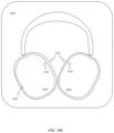
- FIG. 1 A shows a front view of an exemplary set of over ear or on-ear headphones
- FIG. 1 B shows headphone stems extending different distances from a headband assembly
- FIG. 2 A shows a perspective view of a first side of headphones with synchronized headphone stems
- FIGS. 2 B- 2 C show cross-sectional views of the headphones depicted in FIG. 2 A in accordance with section lines A-A and B-B, respectively;
- FIG. 2 D shows a perspective view of an opposite side of the headphones depicted in FIG. 2 A ;
- FIG. 2 E shows a cross-sectional view of the headphones depicted in FIG. 2 D in accordance with section line C-C;
- FIGS. 2 F- 2 G show perspective views of a second side of headphones with synchronized headphone stems and a unitary spring band;
- FIGS. 2 H- 2 I show cross-sectional views of the headphones depicted in FIGS. 2 F- 2 G in accordance with section lines D-D and E-E, respectively;
- FIG. 3 A shows exemplary headphones having a headband assembly configured to synchronize adjustment of the positions of its earpieces
- FIG. 3 B shows a cross-sectional view of a headband assembly when the headphones are expanded to their largest size
- FIG. 3 C shows a cross-sectional view of the headband assembly when the headphones are contracted to a smaller size
- FIGS. 3 D- 3 F show perspective top and cross-sectional views of a headband assembly configured to synchronize earpiece position
- FIGS. 3 G- 3 H show a top view of an earpiece synchronization assembly
- FIGS. 3 I- 3 J show a flattened schematic view of another earpiece synchronization system similar to the one depicted in FIGS. 3 G- 3 H ;
- FIGS. 3 K- 3 L show cutaway views of headphones 360 that are suitable for incorporation of either one of the earpiece synchronization systems depicted in FIGS. 3 G- 3 J ;
- FIGS. 3 M- 3 N show perspective views of the earpiece synchronization system depicted in FIGS. 3 G- 3 H in retracted and extended positions as well as a data synchronization cable;
- FIG. 3 O shows a portion of a canopy structure and how an earpiece synchronization system can be routed through reinforcement members of the canopy structure;
- FIGS. 3 P- 3 Q show gearing located at opposing ends of a headband assembly for another alternative earpiece synchronization system
- FIGS. 4 A- 4 B show front views of headphones having off-center pivoting earpieces
- FIG. 5 A shows an exemplary pivot mechanism that includes torsion springs
- FIG. 5 B shows the pivot mechanism depicted in FIG. 5 A positioned behind a cushion of an earpiece
- FIG. 6 A shows a perspective view of another pivot mechanism that includes leaf springs
- FIG. 6 B- 6 D show a range of motion of an earpiece using the pivot mechanism depicted in FIG. 6 A ;
- FIG. 6 E shows an exploded view of the pivot mechanism depicted in FIG. 6 A ;
- FIG. 6 F shows a perspective view of another pivot mechanism
- FIG. 6 G shows yet another pivot mechanism
- FIGS. 6 H- 6 I show the pivot mechanism depicted in FIG. 6 G with one side removed in order to illustrate rotation of a stem base in different positions;
- FIG. 6 J shows a cutaway perspective view of the pivot assembly of FIG. 6 G disposed within an earpiece housing
- FIGS. 6 K- 6 L show partial cross-sectional side views of the pivot assembly positioned within the earpiece housing with helical springs in relaxed and compressed states;
- FIGS. 6 M- 6 N show side views of two different rotational positions of stem base isolated from its pivot assembly
- FIG. 7 A shows multiple positions of a spring band suitable for use in a headband assembly
- FIG. 7 B shows a graph illustrating how spring force varies based on spring rate as a function of displacement of the spring band depicted in FIG. 7 A ;
- FIGS. 8 A- 8 B show a solution for preventing discomfort caused by headphones wrapping too tightly around the neck of a user
- FIGS. 8 C- 8 D show how separate and distinct knuckles can be arranged along the lower side of a spring band to prevent the spring band from returning to a neutral position;
- FIGS. 8 E- 8 F show how springs joining a headband assembly to earpieces can cooperate with a spring band to set the actual amount of force applied to a user by headphones;
- FIGS. 8 G- 8 H show another way in which to limit the range of motion of a pair of headphones using a low spring-rate band
- FIG. 9 A shows an earpiece of headphones positioned over an ear of a user
- FIG. 9 B shows positions of capacitive sensors beneath a surface and proximate ear contours associated with the ear
- FIG. 10 A shows a top view of an exemplary head of a user wearing headphones
- FIG. 10 B shows a front view of the headphones depicted in FIG. 10 A ;
- FIGS. 10 C- 10 D show top views of the headphones depicted in FIG. 10 A and how earpieces of the headphones are able to rotate about respective yaw axes;
- FIGS. 10 E- 10 F show flow charts describing control methods that can be carried out when roll and/or yaw of the earpieces with respect to the headband is detected;
- FIG. 10 G shows a system level block diagram of a computing device 1070 that can be used to implement the various components described herein;
- FIGS. 11 A- 11 C show foldable headphones
- FIGS. 11 D- 11 F show how earpieces of foldable headphones can be folded towards an exterior-facing surface of a deformable band region
- FIGS. 12 A- 12 B show a headphones embodiment that can be transitioned from an arched state to a flattened state by pulling on opposing sides of a spring band;
- FIGS. 12 C- 12 D show side views of a foldable stem region in arched and flattened states, respectively;
- FIG. 12 E shows a side view of one end of the headphones depicted in FIG. 12 D ;
- FIGS. 13 A- 13 B show partial cross-sectional views of headphones using an off-axis cable to transition between an arched state and a flattened states;
- FIGS. 14 A- 14 C show partial cross-sectional views of headphones having a foldable stem region constrained at least in part by an elongating pin that delays flattening of the headphones through a first portion of the travel of the earpieces of the headphones;
- FIGS. 15 A- 15 F show various views of headband assembly 1500 from different angles and in different states
- FIGS. 16 A- 16 B show a headband assembly in folded and arched states
- FIGS. 17 - 18 show views of another foldable headphones embodiment
- FIG. 19 shows one side of a headband housing as well as a telescoping member extending from the end of a headband housing
- FIG. 20 A shows an exploded view of the side of the headband housing depicted in FIG. 20 A ;
- FIG. 20 B shows a cross-sectional view of a first end of a lower housing component in accordance with section line F-F depicted in FIG. 20 A ;
- FIG. 20 C shows a cross-sectional view of a second end of the lower housing component in accordance with section line G-G depicted in FIG. 20 A ;
- FIG. 20 D shows a perspective view of a bushing, which defines multiple finger channels spaced radially around an interior-facing surface of the bushing;
- FIG. 21 A shows a perspective view of a spring member and one end of a telescoping member
- FIG. 21 B shows spring fingers of the spring member engaged within a first set of opening defined by the end of the telescoping member
- FIG. 21 C shows the spring member shifted so that the spring fingers are engaged within a second set of openings defined by the end of the telescoping member
- FIGS. 21 D- 21 G show various locking mechanisms positioned at an opening defined by a lower housing assembly through which a telescoping assembly extends;
- FIGS. 22 A- 22 E depict various extended and contracted coil configurations for a portion of a synchronization cable disposed within a lower housing component
- FIG. 23 A shows an exploded view of components associated with a data plug
- FIG. 23 B shows a telescoping member fully assembly with threaded fastener fully engaged within a threaded opening in order to keep a data plug securely positioned
- FIG. 23 C shows a cross-sectional view of telescoping member in accordance with section line H-H of FIG. 23 B ;
- FIG. 23 D shows a perspective view of a portion of a data plug
- FIG. 23 E shows a cross-sectional side view of the portion of the data plug and depicts multiple glue channels positioned on opposing sides of the body of the data plug;
- FIG. 23 F shows a data plug glued to a stem base, which is in turn positioned within a recess defined by an earpiece;
- FIG. 23 G shows a cross-sectional view of the data plug disposed within a recess defined by the stem base, which is in turn positioned within a recess of an earpiece;
- FIG. 24 A shows perspective views of an earpiece and an earpad
- FIG. 24 B shows how earpieces of a pair of headphones can have thin earpads without sacrificing user comfort
- FIG. 24 C shows how posts couple a flexible substrate supporting the earpad to earpiece yokes
- FIG. 24 D shows an earpiece and an axis of rotation about which an earpad is configured to bend to accommodate cranial contours of a user's head;
- FIG. 24 E- 24 G depict another earpiece in a configuration designed to account for cranial contours of a user's head
- FIGS. 25 A- 25 C show various views of another earpad configuration formed from multiple layers of material
- FIG. 25 D shows how heat-treated regions of a textile layer are in direct contact with the side of a user's head when the headphones are in active use
- FIGS. 26 A- 26 B show perspective views of an earpad in different orientations
- FIG. 26 C- 26 G show various manufacturing operations for forming an earpad from a block of foam
- FIG. 27 A shows a cross-sectional side view of an exemplary acoustic configuration within an earpiece that could be applied with many of the previously described earpieces;
- FIG. 27 B shows an exterior of the earpiece with an input panel removed to illustrate the shape and size of an interior volume associated with a speaker assembly
- FIG. 27 C shows a microphone mounted within an earpiece
- FIG. 28 shows an earpiece having an input panel, which can form an exterior facing surface of earpiece
- FIGS. 29 A- 29 B show perspective and cross-sectional views of an outline of an earpiece illustrating a position of distributed battery assemblies within the earpiece;
- FIG. 29 C shows how more than two discrete battery assemblies can be incorporated into a single earpiece housing
- FIG. 30 A shows exemplary headphones, which include earpieces joined together by a headband
- FIG. 30 B shows an exemplary carrying/storage case well suited for use with circumaural and supra-aural headphones designs discussed herein;
- FIG. 30 C shows headphones 3000 positioned within a recess of the case
- FIG. 30 D shows a cross-sectional view of an earpiece in accordance with section line K-K of FIG. 30 C ;
- FIG. 30 E shows a carrying case with headphones positioned therein
- FIGS. 31 A- 31 B show an illuminated button assembly suitable for use with the described headphones
- FIGS. 31 C- 31 D show side views of the illuminated button assembly depicted in FIGS. 31 A- 31 B in unactuated and actuated positions, respectively, within a device housing;
- FIG. 31 E shows a perspective view of an illuminated window
- FIGS. 32 A- 32 B show perspective views of a pivot assembly associated with a removable earpiece engaged by a stem base of a headphone band;
- FIGS. 33 A- 33 C show different views of a latching mechanism of a pivot assembly
- FIG. 34 A shows headphones, which includes earpieces mechanically coupled together by a headband assembly
- FIG. 34 B shows a close up view of a stem region of a headband assembly
- FIG. 34 C shows a close up view of a distal end of a telescoping component
- FIG. 34 D shows a cross-sectional view of a distal end of a telescoping component in accordance with section line L-L as depicted in FIG. 34 B ;
- FIG. 34 E shows a cross-sectional view of a distal end of a lower housing component in accordance with section line M-M as depicted in FIG. 34 B ;
- FIGS. 34 F- 34 H show a number of alternative embodiments that allow for a larger or smaller amount of play to be established between a lower housing component and a telescoping component
- FIGS. 34 I- 34 J show configurations including a telescoping component disposed within an interior volume defined by a lower housing component.
- Headphones have been in production for many years, but numerous design problems remain.
- the functionality of headbands associated with headphones has generally been limited to a mechanical connection functioning only to maintain the earpieces of the headphones over the ears of a user and provide an electrical connection between the earpieces.
- the incorporation of headphones into other types of portable listening devices, such as augmented reality and virtual reality headsets has also been slow due to an unwillingness to adapt headphones to new and improved form factors.
- the headband tends to add substantially to the bulk of the headphones, thereby making storage of the headphones problematic.
- Stems connecting the headband to the earpieces that are designed to accommodate adjustment of an orientation of the earpieces with respect to a user's ears also add bulk to the headphones.
- Stems connecting the headband to the earpieces that accommodate elongation of the headband generally allow a central portion of the headband to shift to one side of a user's head. This shifted configuration can look somewhat odd and depending on the design of the headphones can also make the headphones less comfortable to wear.
- the earpiece synchronization component taking the form of a mechanical mechanism disposed within the headband that synchronizes the distance between the earpieces and respective ends of the headband.
- This type of synchronization can be performed in multiple ways.
- the earpiece synchronization component can be a cable extending between both stems that can be configured to synchronize the movement of the earpieces.
- the cable can be arranged in a loop where different sides of the loop are attached to respective stems of the earpieces so that motion of one earpiece away from the headband causes the other earpiece to move the same distance away from the opposite end of the headband.
- the earpiece synchronization component can be a rotating gear embedded within the headband can be configured to engage teeth of each stem to keep the earpieces synchronized.
- One solution to the conventional bulky connections between headphones stems and earpieces is to use a spring-driven pivot mechanism to control motion of the earpieces with respect to the band.
- the spring-driven pivot mechanism can be positioned near the top of the earpiece, allowing it to be incorporated within the earpiece instead of being external to the earpiece. In this way, pivoting functionality can be built into the earpieces without adding to the overall bulk of the headphones.
- Different types of springs can be utilized to control the motion of the earpieces with respect to the headband. Specific examples that include torsional springs and leaf springs are described in detail below.
- the springs associated with each earpiece can cooperate with springs within the headband to set an amount of force exerted on a user wearing the headphones.
- the springs within the headband can be low spring-rate springs configured to minimize the force variation exerted across a large spectrum of users with different head sizes.
- the travel of the low-rate springs in the headband can be limited to prevent the headband from clamping to tightly about the neck of a user when being worn around the neck.
- the flattening headband allows for the arched geometry of the headband to be compacted into a flat geometry, allowing the headphones to achieve a size and shape suitable for more convenient storage and transportation.
- the earpieces can be attached to the headband by a foldable stem region that allows the earpieces to be folded towards the center of the headband. A force applied to fold each earpiece in towards the headband is transmitted to a mechanism that pulls the corresponding end of the headband to flatten the headband.
- the stem can include an over-center locking mechanism that prevents inadvertent return of the headphones to an arched state without requiring the addition of a release button to transition the headphones back to the arched state.
- a solution to the power management problems associated with wireless headphones includes incorporating an orientation sensor into the earpieces that can be configured to monitor an orientation of the earpieces with respect to the band.
- the orientation of the earpieces with respect to the band can be used to determine whether or not the headphones are being worn over the ears of a user. This information can then be used to put the headphones into a standby mode or shut the headphones down entirely when the headphones are not determined to be positioned over the ears of a user.
- the earpiece orientation sensors can also be utilized to determine which ears of a user the earpieces are currently covering. Circuitry within the headphones can be configured to switch the audio channels routed to each earpiece in order to match the determination regarding which earpiece is on which ear of the user.
- FIGS. 1 - 31 E These and other embodiments are discussed below with reference to FIGS. 1 - 31 E ; however, those skilled in the art will readily appreciate that the detailed description given herein with respect to these figures is for explanatory purposes only and should not be construed as limiting.
- FIG. 1 A shows a front view of an exemplary set of over ear or on-ear headphones 100 .
- Headphones 100 includes a band 102 that interacts with stems 104 and 106 to allow for adjustability of the size of headphones 100 .
- stems 104 and 106 are configured to shift independently with respect to band 102 in order to accommodate multiple different head sizes. In this way, the position of earpieces 108 and 110 can be adjusted to position earpieces 108 and 110 directly over the ears of a user.
- this type of configuration allows stems 104 and 106 to become mismatched with respect to band 102 .
- the configuration shown in FIG. 1 B can be less comfortable for a user and additionally lack cosmetic appeal.
- FIGS. 1 A- 1 B also show how stems 104 and 106 extend down to a central portion of earpieces 108 in order to allow earpieces 108 to rotate to accommodate the curvature of a user's head.
- the portions of stems 104 and 106 that extend down around earpieces 108 increase the diameters of earpieces 108 .
- FIG. 2 A shows a perspective view of headphones 200 with a headband 202 configured to solve the problems depicted in FIGS. 1 A- 1 B .
- Headband 202 is depicted without a cosmetic covering to reveal internal features.
- headband 202 can include a wire loop 204 configured to synchronize the movement of stems 206 and 208 .
- Wire guides 210 can be configured to maintain a curvature of wire loop 204 that matches the curvature of leaf springs 212 and 214 .
- Leaf springs 212 and 214 can be configured to define the shape of headband 202 and to exert a force upon the head of a user.
- Each of wire guides 210 can include openings through which opposing sides of wire loop 204 and leaf springs 212 and 214 can pass.
- the openings for wire loop 204 can be defined by low-friction bearings to prevent noticeable friction from impeding the motion of wire loop 204 through the openings.
- wire guides 210 define a path along which wire loop 204 extends between stem housings 216 and 218 .
- Wire loop 204 is coupled to both stem 206 and stem 208 and functions to maintain a distance 120 between an earpiece 122 and stem housing 116 substantially the same as a distance 124 between earpiece 126 and stem housing 118 .
- a first side 204 - 1 of wire loop 204 is coupled to stem 206 and a second side 204 - 2 of wire loop 204 is coupled to stem 208 . Because opposite sides of the wire loop are attached to stems 206 and 208 movement of one of the stems results in movement of the other stem in the same direction.
- FIG. 2 B shows a cross-sectional view of a portion of stem housing 116 in accordance with section line A-A.
- FIG. 2 B shows how a protrusion 228 of stem 206 engages part of wire loop 204 .
- protrusion 228 of stem 206 is coupled with wire loop 204
- wire loop 204 is also pulled causing wire loop 204 to circulate through headband 202 .
- the circulation of wire loop 204 through headband 202 adjusts the position of earpieces 226 , which is similarly coupled to wire loop 204 by a protrusion of stem 208 .
- protrusion 228 can also be electrically coupled to wire loop 204 .
- protrusion 228 can include an electrically conductive pathway 230 that electrically couples wire loop 204 to electrical components within earpiece 222 .
- wire loop 204 can be formed from an electrically conductive material, so that signals can be transferred between components within earpieces 222 and 226 by way of wire loop 204 .
- FIG. 2 C shows another cross-sectional view of stem housing 116 in accordance with section line B-B.
- FIG. 2 C shows how wire loop 204 engages pulley 232 within stem housing 216 .
- Pulley 232 minimizes any friction generated by the movement of earpiece 222 closer or farther away from stem housing 216 .
- wire loop 204 can be routed through a static bearing within stem housing 216 .
- FIG. 2 D shows another perspective view of headphones 200 .
- first side 204 - 1 and second side 204 - 2 of wire loop 204 shift laterally as they cross from one side of headband 202 to the other. This can be accomplished by the openings defined by wire guides 210 being gradually offset so that by the time sides 204 - 1 and 204 - 2 reach stem housing 218 , second side 204 - 2 is centered and aligned with stem 208 , as depicted in FIG. 2 E .
- FIG. 2 E shows how second side 204 - 2 is engaged by protrusion 234 . Because stems 206 and 208 are attached to respective first and second sides of wire loop 204 , pushing earpiece 226 towards stem housing 218 also results in earpiece 222 being pushed towards stem housing 216 . Another advantage of the configuration depicted in FIGS. 2 A- 2 E is that regardless of the direction of travel of stems 206 and 208 , wire loop 204 always stays in tension. This keeps the amount of force needed to extend or retract earpieces 222 and 226 consistent regardless of direction.
- FIGS. 2 F- 2 G show perspective views of headphones 250 .
- Headphones 250 are similar to headphones 200 with the exception that only a single leaf spring 252 is used to connect stem housing 254 to stem housing 256 .
- wire loop 258 can be positioned to either side of leaf spring 252 .
- stems 260 and 262 can be positioned directly between the two sides of wire loop 258 and connected to one side of wire loop 258 by an arm of stems 260 and 262 .
- FIGS. 2 H and 2 I show cross-sectional views of an interior portion of stem housings 254 and 256 .
- FIG. 2 H shows a cross-sectional view of stem housing 254 in accordance with section line D-D.
- FIG. 2 H shows how stem 260 can include a laterally protruding arm 268 that engages wire loop 258 . In this way, laterally protruding arm 268 couples stem 260 to wire loop 258 so that when earpiece 264 is moved earpiece 266 is kept in an equivalent position.
- FIG. 2 I shows a cross-sectional view of stem housing 256 in accordance with section line E-E.
- FIG. 2 I also shows how wire loop 258 can be routed within stem housing 256 by pulleys 270 and 272 . By routing wire loop 258 above stem 262 any interference between wire loop 258 and stem 206 can be avoided.
- FIGS. 3 A- 3 C show another headphones embodiment configured to solve problems described in FIGS. 1 A- 1 B .
- FIG. 3 A shows headphones 300 , which includes headband assembly 302 .
- Headband assembly 302 is joined to earpieces 304 and 306 by stems 308 and 310 .
- a size and shape of headband assembly 302 can vary depending on how much adjustability is desirable for headphones 300 .
- FIG. 3 B shows a cross-sectional view of headband assembly 302 when headphones 300 are expanded to their largest size.
- headband assembly 302 includes a gear 312 configured to engage teeth defined by the ends of each of stems 308 and 310 .
- stems 308 and 310 can be prevented from pulling completely out of headband assembly 302 by spring pins 314 and 316 by engaging openings defined by stems 308 and 310 .
- FIG. 3 C shows a cross-sectional view of headband assembly 302 when headphones 300 are contracted to a smaller size.
- FIG. 3 C shows how gear 312 keeps the position of stems 308 and 310 synchronized on account of any movement of stem 308 or stem 310 being translated to the other stem by gear 312 .
- a stiffness of the housing defining the exterior of headband assembly 302 can be selected to match the stiffness of stems 308 and 310 to provide a user of headphones 300 with a headband having a more consistent feel.
- FIG. 3 D shows an alternative embodiment of stems 308 and 310 .
- a cover concealing the ends of stems 308 and 310 has been removed to more clearly show the features of the mechanism synchronizing the positions of the stems.
- Stem 308 defines an opening 318 extending through a portion of stem 308 .
- One side of opening 318 has teeth configured to engage gear 320 .
- stem 310 defines an opening 322 extending through a portion of stem 310 .
- One side of opening 322 has teeth configured to engage gear 320 . Because opposing sides of openings 318 and 322 engage gear 320 , any motion of one of stems 308 and 310 causes the other stem to move. In this way, earpieces positioned at the ends of each of stem 308 and stem 310 are synchronized.
- FIG. 3 E shows a top view of stems 308 and 310 .
- FIG. 3 E also shows an outline of a cover 324 for concealing the geared openings defined by stems 308 and 310 and controlling the motion of the ends of stems 308 and 310 .
- FIG. 3 F shows a cross-sectional side view of stems 308 and 310 covered by cover 324 .
- Gear 320 can include bearing 326 for defining the axis of rotation for gear 320 .
- the top of bearing 326 can protrude from cover 324 , allowing a user to adjust the earpiece positions by manually rotating bearing 326 . It should be appreciated that a user could also adjust the earpiece positions by simply pushing or pulling on one of stems 308 and 310 .
- FIG. 3 G shows a flattened schematic view of another earpiece synchronization system that utilizes a loop 328 within a headband 330 (the rectangular shape is used merely to show the location of headband 330 and should not be construed as for exemplary purposes only) to keep a distance between each of earpieces 304 and 306 and headband 330 synchronized.
- Stem wires 332 and 334 couple respective earpieces 304 and 306 to loop 328 .
- Stem wires 332 and 334 can be formed of metal and soldered to opposing sides of loop 328 . Because stem wires 332 and 334 are coupled to opposing sides of loop 328 , movement of earpiece 306 in direction 336 results in stem wire 332 moving in direction 338 .
- FIG. 3 H shows how moving earpiece 304 in direction 340 automatically moves earpiece 306 in direction 342 and farther away from headband 330 . While not depicted it should be appreciated that headband 330 could include various reinforcement members to keep loop 328 and stem wires 332 and 334 in the depicted shapes.
- FIGS. 3 I- 3 J show a flattened schematic view of another earpiece synchronization system similar to the one depicted in FIGS. 3 G- 3 H .
- FIG. 3 I shows how the ends of stems 344 and 346 can be coupled directly to each other without an intervening loop.
- stems 344 and 346 By extending stems 344 and 346 into a pattern having a similar shape as loop 328 a similar outcome can be achieved without the need for an additional loop structure. Movement of stems 344 and 346 is assisted by reinforcement members 348 , 350 and 352 , which help to prevent buckling of stems 344 and 346 while the position of earpieces 304 and 306 are being adjusted.
- Reinforcement members 348 - 352 can define channels through which stems 344 and 346 smoothly pass.
- reinforcement member 352 While not defining a curved channel, reinforcement member 352 still serves an important purpose of limiting the direction of travel of the ends of stems 344 and 346 to directions 354 and 356 . Movement in direction 356 results in earpieces moving toward headband 330 , as depicted in FIG. 3 J . Movement in direction 354 results in earpieces 304 and 306 moving farther away from headband 330 .
- FIGS. 3 K- 3 L show cutaway views of headphones 360 that are suitable for incorporation of either one of the earpiece synchronization systems depicted in FIGS. 3 G- 3 J .
- FIG. 3 K shows headphones 360 with earpieces retracted and stem wires 332 and 334 extending out of headband 330 to engage and synchronize a position of stem assembly 362 with a position of stem assembly 364 .
- Stem 334 is depicted coupled to support structure 366 within stem assembly 364 , which allows extension and retraction of stem 334 to keep stem assembly 362 synchronized with stem assembly 364 .
- stem assembly 362 is disposed within a channel defined by headband 330 , which allows stem assembly 362 to move relative to headband 330 .
- FIG. 3 K also shows how data synchronization cable 368 can extend through headband 330 and wrap around a portion of both stem wire 334 and stem wire 332 .
- data synchronization cable 368 is able to act as a reinforcement member to prevent buckling of stem wires 332 and 334 .
- Data synchronization cable 368 is generally configured to exchange signals between earpieces 304 and 306 in order to keep audio precisely synchronized during playback operations of headphones 360 .
- FIG. 3 L shows how the coil configuration of data synchronization cable 368 accommodates extension of stem assemblies 362 and 364 .
- Data synchronization cable 368 can have an exterior surface with a coating that allows stem wires 332 and 334 to slide through a central opening defined by the coils.
- FIG. 3 L also shows how earpieces 304 and 306 maintain the same distance from a central portion of headband 330 .
- FIGS. 3 M- 3 N show perspective views of the earpiece synchronization system depicted in FIGS. 3 G- 3 H in retracted and extended positions as well as a data synchronization cable 368 .
- FIG. 3 M shows how stem wire 332 includes an attachment feature 370 that at least partially surrounds a portion of loop 328 . In this way, stem wire 332 , stem wire 334 and support structures 366 move along with loop 328 .
- FIG. 3 M also shows a dashed line illustrating how a covering for headband 330 can at least partially conform with loop 328 , stem wire 332 and stem wire 334 .
- FIG. 3 O shows a portion of canopy structure 372 and how an earpiece synchronization system can be routed through reinforcement members 374 of canopy structure 372 .
- Reinforcement members 374 help guide loop 328 and stem wire 332 along a desired path.
- canopy structure 372 can include a spring mechanism that helps keep earpieces secured to a user's ears.
- FIGS. 3 P- 3 Q show gearing located at opposing ends of a headband assembly for another alternative earpiece synchronization system.
- FIG. 3 P shows how stem 262 has a first end coupled to an earpiece (not depicted) and a second end coupled to gear 380 .
- gear 380 is rigidly coupled to beveled gear component 386 .
- Beveled gear component 386 in turn induces rotation of beveled gear component 388 .
- Beveled gear component 388 is rigidly coupled to gear 390 . Rotation of gear 390 in turn induces rotation of elongated gear 392 .
- Gears 380 , 386 , 388 and 390 all move together and are guided along a periphery of elongated gear 392 by bearing 394 .
- Elongated gear 392 is in turn coupled to a flexible rotary shaft that includes a cable 396 routed through an associated headband assembly.
- Cable 396 can include layers of high-tensile wire wound over each other at opposing pitch angles that are configured to efficiently transmit rotational motion from one end of cable 396 to another. Rotation of the other end of cable 396 in turn moves a stem at the other end of the headband assembly in sync with stem 262 .
- a diameter of cable 396 can be between about 0.02 inches and 0.25 inches.
- FIG. 3 Q shows a second position of gears 380 , 386 , 388 and 390 after having adjusted a position of stem 262 .
- FIGS. 4 A- 4 B show front views of headphones 400 having off-center pivoting earpieces.
- FIG. 4 A shows a front view of headphones 400 , which includes headband assembly 402 .
- headband assembly 402 can include an adjustable band and stems for customizing the size of headphones 400 .
- Each end of headband assembly 402 is depicted being coupled to an upper portion of earpieces 404 . This differs from conventional designs, which place the pivot point in the center of earpieces 404 so that earpieces can naturally pivot in a direction that allows earpieces 404 to move to an angle in which earpieces 404 are positioned parallel to a surface of a user's head.
- FIG. 4 B shows an exemplary range of motion 408 for each of earpieces 404 .
- Range of motion 408 can be configured to accommodate a majority of users based on studies performed on average head size measurements. This more compact configuration can still perform the same functions as the more traditional configuration described above, which includes applying a force through the center of the earpiece and establishing an acoustic seal.
- range of motion 408 can be about 18 degrees.
- range of motion 408 may not have a defined stop but instead grow progressively harder to deform as it gets farther from a neutral position.
- the pivot mechanism components can include spring elements configured to apply a modest retaining force to the ears of a user when the headphones are in use. The spring elements can also bring earpieces back to a neutral position once headphones 400 are no longer being worn.
- FIG. 5 A shows an exemplary pivot mechanism 500 for use in the upper portion of an earpiece.
- Pivot mechanism 500 can be configured to accommodate motion around two axes, thereby allowing adjustments to both roll and yaw for earpieces 404 with respect to headband assembly 402 .
- Pivot mechanism 500 includes a stem 502 , which can be coupled to a headband assembly.
- One end of stem 502 is positioned within bearing 504 , which allows stem 502 to rotate about yaw axis 506 .
- Bearing 504 also couples stem 502 to torsional springs 508 , which oppose rotation of stem 502 with respect to earpiece 404 about roll axis 510 .
- Each of torsional springs 508 can also be coupled to mounting blocks 512 .
- Mounting blocks 512 can be secured to an interior surface of earpiece 404 by fasteners 514 .
- Bearing 504 can be rotationally coupled to mounting blocks 512 by bushings 516 , which allow bearing 504 to rotate with respect to mounting blocks 512 .
- the roll and yaw axes can be substantially orthogonal with respect to one another. In this context, substantially orthogonal means that while the angle between the two axes might not be exactly 90 degrees that an angle between the two axes would stay between 85 and 95 degrees.
- FIG. 5 A also depicts magnetic field sensor 518 .
- Magnetic field sensor 518 can take the form of a magnetometer or Hall Effect sensor capable of detecting motion of a magnet within pivot mechanism 500 .
- magnetic field sensor 518 can be configured to detect motion of stem 502 with respect to mounting blocks 512 .
- magnetic field sensor 518 can be configured to detect when headphones associated with pivot mechanism 500 are being worn.
- rotation of a magnet coupled with bearing 504 can result in the polarity of the magnetic field emitted by that magnet saturating magnetic field sensor 518 .
- Saturation of the Hall Effect sensor by a magnetic field causes the Hall Effect sensor to send a signal to other electronic devices within headphones 400 by way of flexible circuit 520 .
- FIG. 5 B shows a pivot mechanism 500 positioned behind a cushion 522 of earpiece 404 .
- pivot mechanism 500 can be integrated within earpiece 404 without impinging on space normally left open to accommodate the ear of a user.
- Close-up view 524 shows a cross-sectional view of pivot mechanism 500 .
- close-up view 524 shows a magnet 526 positioned within a fastener 528 .
- Magnetic field sensor 518 can be configured to sense rotation of the field emitted by magnet 526 as it rotates.
- the signal generated by magnetic field sensor 518 can be used to activate and/or deactivate headphones 400 .
- FIG. 5 B Close up view 524 of FIG. 5 B also shows how stem 502 is able to twist within bearing 504 .
- Stem 502 is coupled to threaded cap 530 , which allows stem 502 to twist within bearing 504 about yaw axis 506 .
- threaded cap 530 can define mechanical stops that limit the range of motion through which stem 502 can twist.
- a magnet 532 is disposed within stem 502 and is configured to rotate along with stem 502 .
- a magnetic field sensor 534 can be configured to measure the rotation of a magnetic field emitted by magnet 532 .
- a processor receiving sensor readings from magnetic field sensor 534 can be configured to change an operating parameter of headphones 400 in response to the sensor readings indicating a threshold amount of change in the angular orientation of magnet 532 relative to the yaw axis has occurred.
- FIG. 6 A shows a perspective view of another pivot mechanism 600 that is configured to fit within a top portion of earpieces 404 of headphones.
- the overall shape of pivot mechanism 600 is configured to conform with space available within the top portion of the earpieces.
- Pivot mechanism 600 utilizes leaf springs instead of torsion springs to oppose motion in the directions indicated by arrows 601 of earpieces 404 .
- Pivot mechanism 600 includes stem 602 , which has one end disposed within bearing 604 .
- Bearing 604 allows for rotation of stem 602 about yaw axis 605 .
- Bearing 604 also couples stem 602 to a first end of leaf spring 606 through spring lever 608 .
- a second end of each of leaf springs 606 is coupled to a corresponding one of spring anchors 610 .
- Spring anchors 610 are depicted as being transparent so that the position at which the second end of each of leaf springs 606 engages a central portion of spring anchors 610 can be seen. This positioning allows leaf springs 606 to bend in two different directions.
- Spring anchors 610 couple the second end of each leaf spring 606 to earpiece housing 612 . In this way, leaf springs 606 create a flexible coupling between stem 602 and earpiece housing 612 .
- Pivot mechanism 600 can also include cabling 614 configured to route electrical signals between two earpieces 404 by way of headband assembly 402 (not depicted).
- FIGS. 6 B- 6 D show a range of motion of earpiece 404 .
- FIG. 6 B shows earpiece 404 in a neutral state with leaf springs 606 in an undeflected state.
- FIG. 6 C shows leaf springs 606 being deflected in a first direction and
- FIG. 6 D shows leaf spring 606 being deflected in a second direction opposite the first direction.
- FIGS. 6 C- 6 D also show how the area between cushion 522 and earpiece housing 612 can accommodate the deflection of leaf springs 606 .
- FIG. 6 E shows an exploded view of pivot mechanism 600 .
- FIG. 6 E depicts mechanical stops that govern the amount of rotation possible about yaw axis 605 .
- Stem 602 includes a protrusion 616 , which is configured to travel within a channel defined by an upper yaw bushing 618 .
- the channel defined by upper yaw bushing 618 has a length that allows for greater than 180 degrees of rotation.
- the channel can include a detent configured to define a neutral position for earpiece 404 .
- FIG. 6 E also depicts a portion of stem 602 that can accommodate yaw magnet 620 .
- a magnetic field emitted by magnet 620 can be detected by magnetic field sensor 622 .
- Magnetic field sensor 622 can be configured to determine an angle of rotation of stem 602 with respect to the rest of pivot mechanism 600 .
- magnetic field sensor 622 can be a Hall Effect sensor.
- FIG. 6 E also depicts roll magnet 624 and magnetic field sensor 626 , which can be configured to measure an amount of deflection of leaf springs 606 .
- pivot mechanism 600 can also include strain gauge 628 configured to measure strain generated within leaf spring 606 . The strain measured in leaf spring 606 can be used to determine which direction and how much leaf spring is being deflected. In this way, a processor receiving sensor readings recorded by strain gauge 628 can determine whether and in which direction leaf springs 606 are bending. In some embodiments, readings received from strain gauge can be configured to change an operating state of headphones associated with pivot mechanism 600 .
- the operating state can be changed from a playback state in which media is being presented by speakers associated with pivot mechanism 600 to a standby or inactive state in response to the readings from the strain gauge.
- leaf springs 606 when leaf springs 606 are in an undeflected state this can be indicative of headphones associated with pivot mechanism 600 not being worn by a user.
- the strain gauge can be positioned upon a headband spring. For this reason, ceasing playback based on this input can be very convenient as it allows a user to maintain a location in a media file until putting the headphones back on the head of the user at which point the headphones can be configured to resume playback of the media file.
- Seal 630 can close an opening between stem 602 and an exterior surface of an earpiece in order to prevent the ingress of foreign particulates that could interfere with the operation of pivot mechanism 600 .
- FIG. 6 F shows a perspective view of another pivot mechanism 650 , which differs in some ways from pivot mechanism 600 .
- Leaf springs 652 have a different orientation than leaf springs 606 of pivot mechanism 600 .
- leaf springs 652 are oriented about 90 degrees different than leaf springs 606 . This results in a thick dimension of leaf springs 652 opposing rotation of an earpiece associated with pivot mechanism 650 .
- FIG. 6 F also shows flexible circuit 654 and board-to-board connector 656 . Flexible circuit can electrically couple a strain gauge positioned upon leaf spring 652 to a circuit board or other electrically conductive pathways on pivot mechanism 650 .
- sensor data provided by the strain gauge can be configured to determine whether or not headphones associated with pivot mechanism 650 are being worn by a user of the headphones.
- Pivot mechanism 650 is also depicted including a portion 658 of a stem configured to attach pivot mechanism 650 to a headband.
- FIG. 6 G shows another pivot assembly 660 attached to earpiece housing 612 by fasteners 662 and bracket 663 .
- Pivot assembly 660 can include multiple helical springs 664 arranged side by side. In this way, helical coils 664 can act in parallel increasing the amount of resistance provided by pivot assembly 660 .
- Helical springs 664 are held in place and stabilized by pins 666 and 668 .
- Actuator 670 translates any force received from rotation of stem base 658 to helical springs 664 . In this way, helical springs 664 can establish a desired amount of resistance to rotation of stem base 658 .
- FIGS. 6 H- 6 I show pivot assembly 660 with one side removed in order to illustrate rotation of stem base 658 in different positions.
- FIGS. 6 H- 6 I shows how rotation of stem base 658 results in rotation of actuator 670 and compression of helical springs 664 .
- FIG. 6 J shows a cutaway perspective view of pivot assembly 660 disposed within earpiece housing 612 .
- stem base 658 can include a bearing 674 , as depicted, to reduce friction between stem base 658 and actuator 670 .
- FIG. 6 J also shows how bracket 663 can define a bearing for securing pin 666 in place.
- Pins 666 and 668 are also shown defining flattened recesses for keeping helical springs 664 securely in place.
- the flattened recess can include protrusions that extends into central openings of helical springs 664 .
- FIGS. 6 K- 6 L show partial cross-sectional side views of pivot assembly 660 positioned within earpiece housing with helical springs 664 in relaxed and compressed states.
- actuator 670 when shifting from a first position in FIG. 6 K to a second position of maximum deflection is clearly depicted.
- FIGS. 6 K and 6 L also depict mechanical stop 676 which helps limit an amount of rotation earpiece housing can achieve relative to stem base.
- FIGS. 6 M- 6 N show side views of two different rotational positions of stem base 672 isolated from its pivot assembly.
- two permanent magnets 678 and 680 are shown rigidly coupled to stem base 672 .
- Permanent magnets 678 and 680 emit magnetic fields with polarities oriented in opposing directions.
- Magnetic field sensor 682 is mounted to earpiece housing 612 such that magnetic field sensor 682 remains motionless relative to stem base 672 during rotation of stem base 672 about axis of rotation 684 . In this way, at a first position depicted in FIG. 6 M , magnetic field sensor 682 is positioned proximate permanent magnet 680 and at a second position depicted in FIG. 6 N , magnetic field sensor 682 .
- magnetic field sensor 682 can take the form of a magnetometer or a Hall Effect sensor. Depending on a sensitivity of magnetic field sensor 682 , magnetic field sensor 682 can be configured to measure an approximate angle of stem base 672 relative to earpiece housing 612 . For example, where the depicted rotational positions differ by 20 degrees an intermediate position of 10 degrees could be inferred by sensor readings from magnetic field sensor 682 where the magnetic field directions transition from one direction to another.
- magnetic field sensor 682 can be configured to operate with only a single permanent magnet and be configured to determine rotational position of stem base 672 based solely on a magnetic field strength detected by magnetic field sensor 682 . It should be noted that in alternative embodiments magnetic field sensor 682 can be coupled to stem base 672 and permanent magnets 678 and 680 can be coupled to earpiece housing resulting in magnetic field sensor 682 moving within the earpiece housing.
- FIG. 7 A shows multiple positions of a spring band 700 suitable for use in a headband assembly.
- Spring band 700 can have a low spring rate that causes a force generated by the band in response to deformation of spring band 700 to change slowly as a function of displacement. Unfortunately, the low spring rate also results in the spring having to go through a larger amount of displacement before exerting a particular amount of force.
- Spring band 700 is depicted in different positions 702 , 704 , 706 and 708 .
- Position 702 can correspond to spring band 700 being in a neutral state at which no force is exerted by spring band 700 .
- a spring band 700 can begin exerting a force pushing spring band 700 back toward its neutral state.
- Position 706 can correspond to a position at which users with small heads bend spring band 700 when using headphones associated with spring band 700 .
- Position 708 can correspond to a position of spring band 700 in which the users with large heads bend spring band 700 .
- the displacement between positions 702 and 706 can be sufficiently large for spring band 700 to exert an amount of force sufficient to keep headphones associated with spring band 700 from falling off the head of a user.
- the force exerted by spring band 700 at position 708 can be small enough so that use of headphones associated with spring band 700 is not high enough to cause a user discomfort.
- the lower the spring rate of spring band 700 the smaller the variation in force exerted by spring band 700 . In this way, use of a low spring-rate spring band 700 can allow headphones associated with spring band 700 to give users with different sized heads a more consistent user experience.
- FIG. 7 B shows a graph illustrating how spring force varies based on spring rate as a function of displacement of spring band 700 .
- Line 710 can represent spring band 700 having its neutral position equivalent to position 702 . As depicted, this allows spring band 700 to have a relatively low spring rate that still passes through a desired force in the middle of the range of motion for a particular pair of headphones.
- Line 712 can represent spring band 700 having its neutral position equivalent to position 704 . As depicted, a higher spring rate is required to achieve a desired amount of force being exerted in the middle of the desired range of motion.
- line 714 represents spring band 700 having its neutral position equivalent to position 706 .
- FIG. 8 A- 8 B show a solution for preventing discomfort caused by headphones 800 utilizing a low spring-rate spring band from wrapping too tightly around the neck of a user.
- Headphones 800 include a headband assembly 802 joining earpieces 804 .
- Headband assembly 802 includes compression band 806 coupled to an interior-facing surface of spring band 700 .
- FIG. 8 A shows spring band 700 in position 708 , corresponding to a maximum deflection position of headphones 800 .
- the force exerted by spring band 700 can act as a deterrent to stretching headphones 800 past this maximum deflection position.
- an exterior facing surface of spring band 700 can include a second compression band configured to oppose deflection of spring band 700 past position 708 .
- knuckles 808 of compression band 806 serve little purpose when spring band is in position 708 on account of none of the lateral surfaces of knuckles 808 being in contact with adjacent knuckles 808 .
- FIG. 8 B shows spring band 700 in position 706 .
- knuckles 808 come into contact with adjacent knuckles 808 to prevent further displacement of spring band 700 towards position 704 or 702 .
- compression band 806 can prevent spring band 700 from squeezing the neck of a user of headphones 800 while maintaining the benefits of the low-spring rate spring band 700 .
- FIGS. 8 C- 8 D show how separate and distinct knuckles 808 can be arranged along the lower side of spring band 700 to prevent spring band 700 from returning past position 706 .
- FIGS. 8 E- 8 F show how the use of springs to control the motion of headband assembly 802 with respect to earpieces 804 can change the amount of force applied to a user by headphones 800 when compared to the force applied by spring band 700 alone.
- FIG. 8 E shows forces 810 exerted by spring band 700 and forces 812 exerted by springs controlling the motion of earpieces 804 with respect to headband assembly 802 .
- FIG. 8 F shows exemplary curves illustrating how forces 810 and 812 supplied by at least two different springs can vary based on spring displacement. Force 810 does not begin to act until just prior to the desired range of motion on account of the compression band preventing spring band 700 from returning all the way to a neutral state.
- FIG. 8 F also illustrates force 814 , the result of forces 810 and 812 acting in series.
- FIGS. 8 G- 8 H show another way in which to limit the range of motion of a pair of headphones 850 using a low spring-rate band 852 .
- FIG. 8 G shows cable 854 in a slack state on account of earpieces 856 being pulled apart.
- the range of motion of low spring-rate band 852 can be limited by cable 854 achieving a similar function to the function of compression band 806 , engaging as a result of function of tension instead of compression.
- Cable 854 is configured to extend between earpieces 856 and is coupled to each of earpieces 856 by anchoring features 858 .
- Cable 854 can be held above low spring-rate band 852 by wire guides 860 .
- Wire guides 860 can be similar to wire guides 210 depicted in FIGS.
- wire guides 860 are configured to elevate cable 854 above low spring-rate band 852 . Bearings of wire guides 860 can prevent cable 854 from catching or becoming undesirably tangled. It should be noted that cable 854 and low spring-rate band 852 can be covered by a cosmetic cover. It should also be noted that in some embodiments, cable 854 could be combined with the embodiments shown in FIGS. 2 A- 2 G to produce headphones capable of synchronizing earpiece position and controlling the range of motion of the headphones.
- FIG. 8 H shows how when earpieces 856 are brought closer together cable 854 tightens and eventually stops further movement of earpieces 856 closer together. In this way, a minimum distance 862 between earpieces 856 can be maintained that allows headphones 850 to be worn around the neck of a broad population of users without squeezing the neck of the user too tightly.
- FIG. 9 A shows an earpiece 902 of headphones positioned over an ear 904 of a user.
- Earpiece 902 includes at least proximity sensors 906 and 908 .
- Proximity sensors 906 and 908 are positioned within a recess defined by earpiece 902 resulting in detectably different readings being returned by proximity sensors 906 and 908 depending on which ear earpiece 902 is positioned over. This is possible due to the asymmetric geometry of most user's ears.
- proximity sensor 906 includes a light emitter configured to emit infrared light and an optical receiver configured to detect the emitted light reflecting off ear 904 of the user.
- a processor incorporated within or electrically coupled to proximity sensor 906 can be configured to determine a distance between proximity sensor 906 and proximate portions of ear 904 by measuring the amount of time it takes for infrared pulses emitted by the light emitter to return back to the light detector.
- proximity sensor 906 can also be configured to map a contour of a portion of the ear. This can be accomplished with multiple emitters configured to emit light of different frequencies in different directions. Sensor readings collected by one or more optical receivers configured to detect and distinguish the different frequencies can then be used to determine a distance between proximity sensor 906 and different locations on the ear.
- proximity sensors 906 can be distributed around a circumference of earpiece 902 when even more detail about the shape and position of the ear with respect to the earpiece is desired. For example, in some embodiments, it may be desirable to in addition to identifying which ear the earpiece is positioned upon, identify a rotational position of the ear with respect to the earpiece. Sensor readings could be of sufficiently high quality to identify certain features of ear 904 such as for example an earlobe or a pinna. In some embodiments and as depicted an angle at which infrared light is emitted from proximity sensor 908 can be different than an angle at which infrared light is emitted from proximity sensor 906 .
- proximity sensor 908 would be able to achieve earlier detection due to it being pointed farther outside of the interior of earpiece 902 .
- Proximity sensor 906 with its shallower angle would be able to cover a larger area of ear 904 of the user.
- a capacitive sensor array can be positioned just beneath the surface of earpiece 902 and be configured to identify protruding features of the ear that contact or are in close proximity to surface 912 of earpiece 902 .
- FIG. 9 B shows positions of capacitive sensors 910 beneath surface 912 and proximate ear contours 914 associated with ear 904 .
- Ear contours 914 represent those contours of ear 904 most likely to protrude closest to the array of capacitive sensors 910 .
- Capacitive sensors 910 can be configured to identify portions of the detected contours of ear 904 to determine which ear earpiece 902 is positioned upon as well as any rotation of earpiece 902 relative to ear 904 .
- FIG. 9 B also indicates how both surface 912 and the array of capacitive sensors 910 define openings 916 or perforations through which audio waves are able to pass substantially unattenuated.
- the array of capacitive sensors 910 are shown disposed beneath only a central portion of surface 912 , it should be appreciated that in some embodiments the array of capacitive sensors 912 could be arranged in different patterns resulting in a greater or smaller amount of coverage. For example, in some embodiments capacitive sensors 910 can be distributed across a majority of surface 912 in order to more completely characterize the shape and orientation of ear 904 . In some embodiments, the location and orientation data captured by capacitive sensors 910 and/or proximity sensors 906 / 908 can be used to optimize audio output from speaker disposed within earpiece 902 . For example, an earpiece with an array of audio drivers could be configured to actuate only those audio drivers centered upon or proximate ear 904 .
- FIG. 10 A shows a top view of an exemplary head of a user 1000 wearing headphones 1002 .
- Earpieces 1004 are depicted on opposing sides of user 1000 .
- a headband joining earpieces 1004 is omitted to show the features of the head of user 1000 in greater detail.
- earpieces 1004 are configured to rotate about a yaw axis so they can be positioned flush against the head of user 1000 and oriented slightly towards the face of user 1000 .
- earpieces 1004 when situated over the ears of a user were offset above the x-axis as depicted.
- FIG. 10 B shows a front view of headphones 1002 .
- FIG. 10 B shows yaw axes of rotation 1006 associated with earpieces 1004 and how earpieces 1004 are both oriented toward the same side of headband 1008 joining earpieces 1004 .
- FIGS. 10 C- 10 D show top views of headphones 1002 and how earpieces 1004 are able to rotate about yaw axes of rotation 1006 .
- FIGS. 10 C- 10 D also show earpieces 1004 being joined together by headband 1008 .
- Headband 1008 can include yaw position sensors 1010 , which can be configured to determine an angle of each of earpieces 1004 with respect to headband 1008 . The angle can be measured with respect to a neutral position of earpieces with respect to headband 1008 .
- the neutral position can be a position in which earpieces 1004 are oriented directly toward a central region of headband 1008 .
- earpieces 1004 can have springs that return earpieces 1004 to the neutral position when not being acted upon by an external force.
- the angle of earpieces relative to the neutral position can change in a clockwise direction or counter clockwise direction.
- earpiece 1004 - 1 is biased about axis of rotation 1006 - 1 in a counter clockwise direction
- earpiece 1004 - 2 is biased about axis of rotation 1006 - 2 in a clockwise direction.
- sensors 1010 can be time of flight sensors configured to measure angular change of earpieces 1004 .
- sensors 1010 can represent an optical pattern allowing accurate measurement of an amount of rotation of each of the earpieces.
- sensors 1010 can take the form of magnetic field sensors or Hall Effect sensors as described in conjunction with FIGS. 5 B and 6 E .
- sensors 1010 can be used to determine which ear each earpiece is covering for a user. Because earpieces 1004 are known to be oriented behind the x-axis for almost all users, when sensors 1010 detect both earpieces 1004 oriented to towards one side of the x-axis headphones 1002 can determine which earpieces are on which ear. For example, FIG.
- circuitry within headphones 1002 can be configured to adjust the audio channels so the correct channel is being delivered to the correct ear.
- FIG. 10 D shows a configuration in which earpiece 1004 - 1 is on the right ear of a user and earpiece 1004 - 2 is on the left ear of a user.
- headphones 1002 can request further input prior to changing audio channels.
- a processor associated with headphones 1002 can determine headphones 1002 are not in current use.
- headphones 1002 can include an override switch for the case where the user wants to flip the audio channels independent of the L/R audio channel routing logic associated with yaw position sensors 1010 .
- another sensor or sensors can be activated to confirm the position of headphones 1002 relative to the user.
- FIGS. 10 E- 10 F show flow charts describing control methods that can be carried out when roll and/or yaw of the earpieces with respect to the headband is detected.
- FIG. 10 E shows a flow chart that describes a response to detection of rotation of earpieces with respect to a headband of headphones about a yaw axis.
- the yaw axes can extend through a point located near the interface between each earpiece and the headband.
- the yaw axes can be substantially parallel to a vector defining the intersection of the sagittal and coronal anatomical planes of the user.
- rotation of the earpieces about the yaw axes can be detected by a rotation sensor associated with a pivot mechanism.
- the pivot mechanism can be similar to pivot mechanism 500 or pivot mechanism 600 , which depict yaw axes 506 and 605 .
- a determination can be made regarding whether a threshold associated with rotation about the yaw axis has been exceeded.
- the yaw threshold can be met anytime the earpieces pass through a position where the ear-facing surfaces of the two earpieces can be facing directly towards one another.
- the audio channels being routed to the two earpieces can be swapped.
- the user can be notified of the change in audio channels.
- an amount of roll detected by the pivot mechanism can be factored into a determination of how to assign the audio channels.
- FIG. 10 F shows a flow chart that describes a method for changing the operating state of headphones based on sensor readings from one or more sensors of the headphones.
- headphones can be put in a hibernating state in which little or no power is expended. In this way, headphones 1062 can have a substantial amount of battery power left on delivery. Delivery personnel could carry out a special procedure in order to remove the headphones from the hibernation state. For example, a data connector engaged with a charging port of the headphones could be removed triggering removal from the hibernation state.
- the headphones can be in a suspended state whenever they have not been used for a threshold amount of time. In the suspended state sensor polling rates can be substantially reduced to further conserve power.
- the headphones may take longer than normal to identify a user attempting to use the headphones.
- a strain gauge or capacitive sensor can be used to identify placement of the headphones on a user's head.
- the method can include returning to the suspended state at 1063 when a motion time out occurs or a strain gauge indicates the headphones are not being worn.
- capacitive or proximity type sensors can be used to sense the presence and/or orientation of ears within the earpieces.
- input controls can be activated.
- media playback can begin by routing audio channels received wirelessly or via a wired cable to corresponding earpieces. Removing headphones from a user's ears can result in a return to 1064 at which time the sensors can go back through the various steps to correctly identify earpiece locations and orientations.
- FIG. 10 G shows a system level block diagram of a computing device 1070 that can be used to implement the various components described herein, according to some embodiments.
- the computing device 1070 can include a processor 1072 that represents a microprocessor or controller for controlling the overall operation of computing device 1070 .
- the computing device 1070 can include first and second earpieces 1074 and 1076 joined by a headband assembly, the earpieces including speakers for presenting media content to the user.
- Processor 1072 can be configured to transmit first and second audio channels to first and second earpieces 1074 and 1076 .
- first orientation sensor(s) 1078 can be configured to transmit orientation data of first earpiece 1074 to processor 1072 .
- second orientation sensor(s) 1080 can be configured to transmit orientation data of second earpiece 1076 to processor 1072 .
- Processor 1072 can be configured to swap the 1st Audio Channel with the 2nd Audio Channel in accordance with information received from first and second orientation sensors 1078 and 1080 .
- a data bus 1082 can facilitate data transfer between at least battery/power source 1084 , wireless communications circuitry 1084 , wired communications circuitry 1082 computer readable memory 1080 and processor 1072 .
- processor 1072 can be configured to instruct battery/power source 1084 in accordance with information received by first and second orientation sensors 1078 and 1080 .
- Wireless communications circuitry 1086 and wired communications circuitry 1088 can be configured to provide media content to processor 1072 .
- processor 1072 , wireless communications circuitry 1086 and wired communications circuitry 1088 can be configured to transmit and receive information from computer-readable memory 1090 .
- Computer readable memory 1090 can include a single disk or multiple disks (e.g. hard drives) and includes a storage management module that manages one or more partitions within computer readable memory 1090 .
- FIGS. 11 A- 11 B show headphones 1100 having a deformable form factor.
- FIG. 11 A shows headphones 1100 including deformable headband assembly 1102 , which can be configured to mechanically and electrically couple earpieces 1104 .
- earpieces 1104 can be ear cups and in other embodiments, earpieces 1104 can be on-ear earpieces.
- Deformable headband assembly 1102 can be joined to earpieces 1104 by foldable stem regions 1106 of headband assembly 1102 . Foldable stem regions 1106 are arranged at opposing ends of deformable band region 1108 .
- Each of foldable stem regions 1106 can include an over-center locking mechanism that allows each of earpieces 1104 to remain in a flattened state after being rotated against deformable band region 1108 .
- the flattened state refers to the curvature of deformable band region 1108 changing to become flatter than in the arched state.
- deformable band region 1108 can become very flat but in other embodiments the curvature can be more variable (as shown in the following figures).
- the over-center locking mechanism allows earpieces 1104 to remain in the flattened state until a user rotates the over-center locking mechanism back away from deformable band region 1108 . In this way, a user need not find a button to change the state, but simply perform the intuitive action of rotating the earpiece back into its arched state position.
- FIG. 11 B shows one of earpieces 1104 rotated into contact with deformable band region 1108 .
- rotation of just one of earpieces 1104 against deformable band region 1108 causes half of deformable band region 1108 to flatten.
- FIG. 11 C shows the second one of earpieces rotated against deformable band region 1108 .
- headphones 1100 can be easily transformed from an arched state (i.e. FIG. 11 A ) to a flattened state (i.e. FIG. 11 C ).
- the size of headphones 1100 can be reduced to a size equivalent to two earpieces arranged end to end.
- deformable band region can press into cushions of earpieces 1104 , thereby substantially preventing headband assembly 1102 from adding to the height of headphones 1100 in the flattened state.
- FIGS. 11 D- 11 F show how earpieces 1104 of headphones 1150 can be folded towards an exterior-facing surface of deformable band region 1108 .
- FIG. 11 D shows headphones 11 D in an arched state.
- FIG. 11 E one of earpieces 1104 is folded towards the exterior-facing surface of deformable band region 1108 .
- the force exerted in moving earpiece 1104 to this position can place one side of deformable headband assembly 1102 in a flattened state while the other side stays in the arched state.
- the second earpiece 1104 is also shown folded against the exterior-facing
- FIGS. 12 A- 12 B show a headphones embodiment in which the headphones can be transitioned from an arched state to a flattened state by pulling on opposing ends of a spring band.
- FIG. 12 A shows headphones 1200 , which can be, for example, headphones 1100 shown in FIG. 11 , in a flattened state. In the flattened state, earpieces 1104 are aligned in the same plane so that each of earpads 1202 face in substantially the same direction. In some embodiments, headband assembly 1102 contacts opposing sides of each of earpads 1202 in the flattened state.
- Deformable band region 1108 of headband assembly 1102 includes spring band 1204 and segments 1206 .
- Spring band 1204 can be prevented from returning headphones 1200 to the arched state by locking components of foldable stem regions 1106 exerting pulling forces on each end of spring band 1204 .
- Segments 1206 can be connected to adjacent segments 1206 by pins 1208 . Pins 1208 allow segments to rotate relative to one another so that the shape of segments 1206 can be kept together but also be able to change shape to accommodate an arched state.
- Each of segments 1206 can also be hollow to accommodate spring band 1204 passing through each of segments 1206 .
- a central or keystone segment 1206 can include fastener 1210 , which engages the center of spring band 1204 . Fastener 1210 isolates the two side of spring band 1204 allowing for earpieces 1104 to be sequentially rotated into the flattened state as depicted in FIG. 11 B .
- FIG. 12 A also shows each of foldable stem regions 1106 which include three rigid linkages joined together by pins that pivotally couple upper linkage 1212 , middle linkage 1214 and lower linkage 1216 together.
- Motion of the linkages with respect to each other can also be at least partially governed by spring pin 1218 , which can have a first end coupled to a pin 1220 joining middle linkage 1214 to lower linkage 1216 and a second end engaged within a channel 1222 defined by upper linkage 1212 .
- the second end of spring pin 1218 can also be coupled to spring band 1204 so that as the second end of spring pin 1218 slides within channel 1222 the force exerted upon spring band 1204 changes.
- Headphones 1200 can snap into the flattened state once the first end of spring pin 1218 reaches an over-center locking position.
- the over-center locking position keeps earpiece 1104 in the flattened position until the first end of spring pin 1218 is moved far enough to be released from the over-center locking position. At that point, earpiece 1104 returns to its arched state position.
- FIG. 12 B shows headphones 1200 arranged in an arched state.
- spring band 1204 is in a relaxed state where a minimal amount of force is being stored within spring band 1204 .
- the neutral state of spring band 1204 can be used to define the shape of headband assembly 1102 in the arched state when not being actively worn by a user.
- FIG. 12 B also shows the resting state of the second end of spring pins 1218 within channels 1222 and how the corresponding reduction in force on the end of spring band 1204 allows spring band 1204 to help headphones 1200 assume the arched state. It should be noted that while substantially all of spring band 1204 is depicted in FIGS. 12 A- 12 B that spring band 1204 would generally be hidden by segments 1206 and upper linkages 1212 .
- FIGS. 12 C- 12 D show side views of foldable stem region 1106 in arched and flattened states, respectively.
- FIG. 12 C shows how forces 1224 exerted by spring pin 1218 operate to keep linkages 1212 , 1214 and 1216 in the arched state.
- spring pin 1218 keeps the linkages in the arched state by preventing upper linkage 1212 from rotating about pin 1226 and away from lower linkage 1216 .
- FIG. 12 D shows how forces 1228 exerted by spring pin 1218 operate to keep linkages 1212 , 1214 and 1216 in the flattened state. This bi-stable behavior is made possible by spring pin 1218 being shifted to an opposite side of the axis of rotation defined by pin 1226 in the flattened state.
- linkages 1212 - 1216 are operable as an over-center locking mechanism.
- spring pin 1218 resists transitioning the headphones from moving from the flattened state to the arched state; however, a user exerting a sufficiently large rotational force on earpiece 1104 can overcome the forces exerted by spring pin 1218 to transition the headphones between the flat and arched states.
- FIG. 12 E shows a side view of one end of headphones 1200 in the flattened state.
- earpads 1202 are shown with a contour configured to conform to the curvature of the head of a user.
- the contour of earpads 1202 can also help to prevent headband assembly 1102 and particularly segments 1206 making up headband assembly 1102 from protruding substantially farther vertically than earpads 1202 .
- the depression of the central portion of earpads 1202 can be caused at least in part by pressure exerted on them by segments 1206 .
- FIGS. 13 A- 13 B show partial cross-sectional views of headphones 1300 , which use an off-axis cable to transition between an arched state and a flattened state.
- FIG. 13 A shows a partial cross-sectional view of headphones 1300 in an arched state.
- Headphones 1300 differ from headphones 1200 in that when earpieces 1104 are rotated towards headband assembly 1102 a cable 1302 is tightened in order to flatten deformable band region 1108 of headband assembly 1102 .
- Cable 1302 can be formed from a highly elastic cable material such as NitinolTM, a Nickel Titanium alloy.
- Close-up view 1303 shows how deformable band region 1108 can include many segments 1304 that are fastened to spring band 1204 by fasteners 1306 .
- fasteners 1306 can also be secured to spring band 1204 by an O-ring to prevent any rattling of fasteners 1306 while using headphones 1300 .
- a central one of segments 1304 can include a sleeve 1308 that prevents cable 1302 from sliding with respect to the central one of segments 1304 .
- the other segments 1304 can include metal pulleys 1310 that keep cable 1302 from experiencing substantial amounts of friction as cable 1302 is pulled on to flatten headphones 1300 .
- FIG. 13 A also shows how each end of cable 1302 is secured to a rotating fastener 1312 . As foldable stem region 1106 rotates, rotating fasteners 1312 keeps the ends of cable 1302 from twisting.
- FIG. 13 B shows a partial cross-sectional view of headphones 1300 in a flattened state.
- Rotating fasteners 1312 are shown in a different rotational position to accommodate the change in orientation of cable 1302 .
- the new location of rotating fasteners 1312 also generates an over-center locking position that prevents headphones 1300 from being inadvertently returned to the arched state as described above with respect to headphones 1200 .
- FIG. 13 B also shows how the curved geometry of each of segments 1304 allows segments 1304 to rotate with respect to one another in order to transition between the arched and flattened states.
- cable 1302 can also be operative to limit a range of motion of spring band 1204 similar in some ways to the embodiment shown in FIGS. 9 A- 9 B .
- Headphones 1300 also include input panels 1314 affixed to an outward facing surface of headphones 1300 in the flattened state.
- Input panels 1314 can define a touch sensitive input surface allowing users to input operating instructions into headphones 1300 when headphones 1300 are in the flattened state. For example, a user might wish to continue media playback with headphones 1300 in the flattened state. Easy access to input panels 1314 would make controlling operation of headphones 1300 in this state straightforward and convenient.
- FIG. 14 A shows headphones 1400 that are similar to headphones 1300 .
- headphones 1400 also use cable 1302 to flatten deformable band region 1108 .
- a central portion of cable 1302 is retained by the central segment 1304 .
- lower linkage 1216 of foldable stem region 1106 is shifted upward with respect to lower linkage 1216 depicted in FIG. 12 A .
- spring pin 1404 is configured to elongate as shown in FIG. 14 B during a first portion of the rotation. In some embodiments, elongation of spring pin 1404 can allow earpiece to rotate about 30 degrees from an initial position.
- FIGS. 15 A- 15 F show various views of headband assembly 1500 from different angles and in different states.
- Headband assembly 1500 has a bi-stable configuration that accommodates transitioning between flattened and arched states.
- FIGS. 15 A- 15 C depict headband assembly 1500 in an arched state.
- Bi-stable wires 1502 and 1504 are depicted within a flexible headband housing 1506 .
- Headband housing can be configured to change shape to accommodate at least the flattened and arched states.
- Bi-stable wires 1502 and 1504 extend from one end of headband housing 1506 to another and are configured to apply a clamping force through earpieces attached to opposing ends of headband assembly 1500 to a user's head to keep an associated pair of headphone securely in place during use.
- headband housing 1506 in particular shows how headband housing 1506 can be formed from multiple hollow links 1508 , which can be hinged together and cooperatively form a cavity within which bi-stable wires 1502 are able to transition between configurations corresponding to the arched and flattened states. Because links 1508 are only hinged on one side, the links are only able to move to the arched state in one direction. This helps avoid the unfortunate situation where headband assembly 1500 is bent the wrong direction, thereby position the earpieces in the wrong direction.
- FIGS. 15 D- 15 F show headband assembly in a flattened state. Because the ends of bi-stable wires 1502 and 1504 have passed an over-center point where the ends of wires 1502 and 1504 are higher than a central portion of bi-stable wires 1502 and 1504 , the bi-stable wires 1502 now help keep headband assembly 1500 in the flattened state. In some embodiments, bi-stable wires 1502 can also be used to carry signals and/or power through headband assembly 1500 from one earpiece to another.
- FIGS. 16 A- 16 B show headband assembly 1600 in folded and arched states.
- FIG. 16 A shows headband assembly 1600 in the arched state.
- Headband assembly similarly to the embodiment shown in FIGS. 15 C and 15 F includes multiple hollow links 1602 that cooperatively form a flexible headband housing that define an interior volume.
- Passive linkage hinge 1604 can be positioned within a central portion of the interior volume and link bi-stable elements 1606 together.
- FIG. 16 A shows bi-stable elements 1606 and 16008 in arched configurations that resist forces acting to squeeze opposing sides of headband assembly 1600 .
- headband assembly 1600 can transition from the arched state depicted in FIG. 16 A to the folded state depicted in FIG. 16 B .
- Passive linkage hinge 1604 accommodates headphone assembly 1600 being folding around a central region 1614 of headband assembly 1600 .
- FIG. 16 B shows how passive linkage hinge 1604 bends to accommodate the folded state of headband assembly 1600 .
- Bi-stable elements 1606 and 1608 are shown configured in folded configurations in order to bias the opposing sides of headband assembly 1600 toward one another, thereby opposing an inadvertent change in state.
- the folded configuration depicted in FIG. 16 B , has the benefit of taking up a substantially smaller amount of space by allowing the open area defined by headband assembly 1600 for accommodating the head of a user to be collapsed so that headband assembly 1600 can take up less space when not in active use.
- FIGS. 17 - 18 show various views of foldable headphones 1700 .
- FIG. 17 shows a top view of headphones 1700 in a folded state.
- Headband 1702 which extends between earpieces 1704 and 1706 , includes wires 1708 and springs 1710 .
- wires 1708 and spring 1710 are straight and in a relaxed state or neutral state.
- FIG. 18 shows a side view of headphones 1700 in an arched state. Headphones 1700 can be transitioned from the folded state depicted in FIG. 17 to the arched state depicted in FIG. 18 by rotating earpieces 1704 and 1706 away from headband 1702 .
- Earpieces 1704 and 1706 each include an over-center mechanism 1802 that applies tension to the ends of wires 1708 to keep wires 1708 in tension in order to maintain an arched state of headband 1702 .
- Wires 1708 help maintain the shape of headband 1702 by exerting forces at multiple locations along springs 1710 through wire guides 1804 , which are distributed at regular intervals along headband 1702 .
- FIG. 19 shows one side of a headband housing 1902 as well as telescoping member 1904 extending from the end of headband housing 1902 .
- Headband housing 1902 can be configured to accommodate telescoping motion of telescoping member 1904 .
- Headband housing 1902 defines multiple channels 1906 , which help guide spring fingers 1908 associated with telescoping member 1904 as telescoping member 1904 slides into and out of lower headband housing 1902 .
- FIG. 19 also depicts a portion of synchronization cable 1910 visible through channel 1906 and coiled within headband housing 1902 .
- the coiled configuration of synchronization cable 1910 allows synchronization cable 1910 to accommodate the changes in length caused by telescoping of telescoping member 1904 relative to headband housing 1902 .
- FIG. 20 A shows an exploded view of the side of headband housing 1902 depicted in FIG. 19 .
- headband housing 1902 is depicted including upper housing component 2002 and lower housing component 2004 .
- Lower housing component 2004 is configured to receive telescoping member 1904 .
- Lower housing component 2004 is depicted defining multiple channels 1906 and an annular bushing 2006 is disposed within one end of lower housing component 2004 and configured to control the motion of telescoping member 1904 relative to lower housing component 2004 by generating friction during movement of telescoping member 1904 .
- FIG. 20 A also depicts spring member 2008 as a single piece that includes multiple spring fingers 2010 configured to engage channels 1906 .
- FIG. 20 B shows a cross-sectional view of a first end of lower housing component 2004 in accordance with section line F-F.
- Lower housing component 2004 is depicted engaged with telescoping member 1810 and bushing 2012 is positioned within telescoping member 1810 .
- One of spring fingers 2008 is shown engaged within channel 1906 of lower housing component 2004 .
- channel 1906 does not extend entirely through a wall of lower housing component 2004 as depicted in FIG. 20 C . This allows spring finger 2008 to be engaged within channel 1906 without it being cosmetically visible from an exterior of lower housing component 2004 .
- FIG. 20 C shows a cross-sectional view of a second end of lower housing component 2004 in accordance with section line G-G.
- the second end of lower housing component 2004 is depicted engaged with upper housing component 2002 .
- Synchronization cable 1910 is shown extending through an opening defined by both upper housing component 2002 and lower housing component 2004 .
- FIG. 20 D shows a perspective view of bushing 2006 , which defines multiple finger channels 2012 spaced radially around an interior-facing surface of bushing 2006 .
- Finger channels 2012 can be configured to align spring fingers 2010 with finger channels 2012 of lower housing component 2004 .
- FIG. 21 A shows a perspective view of spring member 2014 and one end of telescoping member 1810 .
- spring member 2014 includes three spring fingers 2008 .
- Each of spring fingers 2008 includes a locking feature 2102 configured to prevent disengagement of spring member 2014 from telescoping member 1810 .
- Telescoping member 1810 defines a set of corresponding openings 2104 and 2106 divided by a bridging member 2108 . When spring fingers 2008 are engaged within openings 2104 a length of opening 2104 allows each of spring fingers 2008 to be deflected through openings 2104 so that telescoping member 1810 can be inserted into lower housing component 2004 .
- FIG. 21 B shows spring fingers 2008 engaged within openings 2104 and FIG. 21 C shows spring fingers 2008 engaged within openings 2106 .
- spring member 2014 cannot be removed and remain engaged within channels 1906 .
- bridging members 2108 prevent spring fingers 2008 from deflecting any farther into an interior volume 2110 defined by telescoping member 1810 . This keeps protruding portions of spring fingers 2008 securely engaged within corresponding channels 1906 .
- spring member 2014 can be shifted from the position depicted in FIG. 21 B by pulling back on telescoping member 1810 once spring fingers 2008 are engaged within channels 1906 . In this way, spring fingers 2008 can be shifted from openings 2104 into openings 2106 .
- FIGS. 21 D- 21 G show various locking mechanisms positioned at an opening defined by lower housing component 2004 through which telescoping member 1810 extends.
- FIGS. 21 D- 21 E show locking mechanism 2112 .
- FIG. 21 D when locking mechanism 2112 is turned in a first direction 2114 , telescoping member 1810 is able to be translated into or out of lower housing component 2004 , as indicated by two-sided arrow 2116 .
- FIG. 21 E shows how subsequently turning locking mechanism 2112 in direction 2118 causes a position of telescoping member 1810 to be fixed relative to lower housing component 2004 .
- FIGS. 21 F- 21 G show locking mechanism 2120 .
- FIG. 21 F shows how when locking mechanism 2120 is pulled away from lower housing component 2004 and toward telescoping member 1810 in direction 2122 , telescoping member 1810 is able to be translated into or out of lower housing component 2004 , as depicted by two-sided arrow 2124 .
- FIG. 21 G shows how when locking mechanism 2120 is then pushed toward lower housing component 2004 in direction 2126 , a position of telescoping member 1810 relative to lower housing component 2004 is fixed.
- FIGS. 22 A- 22 E depict various extended and contracted coil configurations for a portion of synchronization cable 2010 disposed within lower housing component 2004 .
- FIG. 22 A shows a partial cross-sectional view of a portion of synchronization cable 2010 in a conventional helical coil configuration.
- this configuration can be susceptible to individual loops 2202 shifting laterally when transitioning from the extended configuration 2204 to contracted configuration 2206 as depicted. Misalignment can lead to synchronization cable 2010 rubbing an interior of lower housing component 2004 and becoming frayed over time due to undesired friction inducing failure by fatigue of synchronization cable 2010 .
- FIG. 22 B shows how a cross-sectional shape of synchronization cable 2010 can be adjusted to include alignment features that help prevent loops 2212 of synchronization coil 2010 from becoming misaligned.
- opposing sides of loops 2212 can include alignment features having complementary geometries that help to self-align loops 2212 of synchronization coil 2010 when contracted, as depicted.
- FIG. 22 C shows how a cross-sectional shape of synchronization cable 2010 can be adjusted to include alignment features that help prevent loops 2222 of synchronization coil 2010 from becoming misaligned.
- opposing sides of loops 2222 can include alignment features taking the form of concave channels 2224 and convex ridges 2226 that help to self-align loops 2212 of synchronization coil 2010 when contracted, as depicted.
- FIG. 22 D shows how a cross-sectional shape of synchronization cable 2010 can be adjusted to include linking features that help prevent loops 2232 of synchronization coil 2010 from becoming misaligned.
- opposing sides of loops 2232 can include linking features taking the form of complementary hooks 2234 and convex ridges 2226 that help to self-align loops 2212 of synchronization coil 2010 when contracted, as depicted.
- the linking features also help to define a maximum amount of longitudinal extension of synchronization cable 2010 .
- FIG. 22 E shows another configuration in which synchronization cable 2010 can be prevented from becoming misaligned.
- synchronization cable 2010 By winding synchronization cable 2010 around a shaft 2342 , synchronization cable 2010 can be kept from becoming misaligned even though it is arranged as a helical coil.
- Shaft 2342 should be formed from a stiff material unlikely to go substantial amounts of bending, while also allowing for slight changes in curvature to accommodate motion of telescoping member 1810 .
- shaft 2242 can be formed from NITINOL (a nickel-titanium alloy) wire.
- FIG. 23 A shows an exploded view of components associated with a data plug 2302 .
- data plug 2302 which extends from one end of stem base 2304 is configured to engage a receptacle within telescoping member 1810 .
- threaded fastener 2306 Once engaged within the receptacle, data plug 2302 can be kept securely in place using threaded fastener 2306 , which is configured to engage a recess 2308 defined by a base portion of data plug 2302 through threaded opening 2310 .
- Seal rings 2312 can also be used to further secured data plug 2302 within telescoping member 1810 .
- FIG. 23 B shows telescoping member 1810 fully assembly with threaded fastener 2306 fully engaged within threaded opening 2310 in order to keep data plug 2302 securely positioned.
- FIG. 23 C shows a cross-sectional view of telescoping member 1810 in accordance with section line H-H of FIG. 23 B .
- FIG. 23 C shows one end of data plug 2302 engaged within plug receptacle 2314 .
- FIG. 23 C also shows how threaded fastener cooperates with recess 2308 to keep data plug 2302 secured in place.
- a position of seal rings 2312 is also shown relative to data plug 2302 . It should be noted that in some embodiments data plug 2302 could be omitted in lieu of a cable terminating in a board to board connect that engages a printed circuit board within an associated earpiece of the headphones.
- FIG. 23 D shows a perspective view of a portion of data plug 2302 .
- the body of data plug 2302 has a stepped geometry and defines multiple glue channels 2316 spaced at a regular interval.
- glue channels 2316 can be laser cut into an exterior side surface of the body of data plug 2302 .
- FIG. 23 E shows a cross-sectional side view of the portion of data plug 2302 and depicts multiple glue channels 2316 positioned on opposing sides of the body of data plug 2302 .
- FIG. 23 F shows data plug 2302 glued to stem base 2304 , which is in turn positioned within a recess 2318 defined by earpiece 2320 .
- FIG. 23 G shows a cross-sectional view of data plug 2302 disposed within a recess defined by stem base 2304 , which is in turn positioned within recess 2318 of earpiece 2320 .
- FIG. 23 G corresponds to section line I-I as depicted in FIG. 23 F and also shows how data plug 2302 is adhered to stem base 2304 by an adhesive layer 2322 .
- a strength of a bond formed by adhesive layer 2322 between stem base 2304 and the body of data plug 2302 is substantially increased due to adhesive layer 2322 being able to engage glue channels 2316 .
- an interior-facing surface of stem base 2304 can also include glue channels similar to glue channels 2316 for even greater adhesion.
- one or both of the surfaces contacting adhesive layer 2322 can be roughened, thereby increasing the surface energy of the surfaces and improving the strength of a resulting adhesive coupling.
- FIG. 23 G also depicts a data synchronization cable 2324 extending through channels defined by both data plug 2302 and stem base 2304 .
- FIG. 24 A shows perspective views of earpiece 2402 and earpad 2404 .
- Earpad 2404 is shown having a planar shape illustrating how the side of a user's head 2406 is anything but flat.
- One reason most earpads are quite robust in thickness is to accommodate the cranial contours of the side of a user's head.
- the dashed arrows depicted in FIG. 24 A illustrate the variance in distance earpads need to overcome to conform with the cranial contours.
- FIG. 24 B shows how earpieces 2412 and 2414 of headphones 2410 can have thin earpads 2416 without sacrificing user comfort.
- Earpads 2416 can include a flexible substrate that allows for a predetermined amount of flexure to accommodate variations in cranial contours.
- Earpads 2416 can be coupled to earpiece yokes 2418 with two posts 2420 positioned in locations corresponding to normally low points on a user's head. In the depicted configuration, the portions of earpads 2416 encountering protruding cranial contours can bend back to prevent pressure points on a user's head. In this way, a substantial amount of weight and material cost can be saved since thinner pads can be utilized without sacrificing user comfort.
- FIG. 24 C shows how posts 2420 couple flexible substrate 2422 to earpiece yokes 2418 .
- Flexible substrate 2422 is formed from a substrate having a flexibility sufficient to allow for deformation of earpads 2416 mounted to flexible substrate 2422 . It should be noted that many components have been removed from earpiece 2414 in FIG. 24 C to clearly show how flexible substrate 2422 is connected to earpiece yoke 2418 .
- FIG. 24 D shows earpiece 2414 and an axis of rotation 2424 about which earpad 2416 is configured to bend to accommodate cranial contours of a user's head. Axis of rotation 2424 is defined by the locations at which posts 2420 attach to a rear-facing surface of flexible substrate 2422 and consequently earpad 2416 .
- FIG. 24 E- 24 H depict another earpiece in a configuration designed to account for cranial contours of a user's head.
- FIG. 24 E shows a side view of earpiece 2430 .
- Earpiece 2430 includes convex input panel 2432 , earpiece housing 2434 and earpad assembly 2436 .
- Convex input panel 2432 can be affixed to one side of earpiece housing 2434 and include sensors for receiving touch inputs to headphones associated with the earpiece.
- FIG. 24 E also depicts compressible earpad 2438 of earpad assembly 2436 .
- Compressible earpad 2438 can be formed from foam and have a substantially uniform thickness. By bending compressible earpad 2438 as depicted into a curved geometry a user-facing surface of earpad assembly 2436 can be shaped to match cranial contours of a user's head.
- FIG. 24 F shows a cross-sectional view of earpiece 2430 as well as a shape of a cavity 2440 for accommodating an ear 2442 .
- speaker assembly 2444 can protrude into cavity 2440 without affecting the amount of space available for ear 2442 . In some embodiments, pushing speaker assembly 2444 forward in this manner can reduce the overall size of earpiece 2430 .
- FIG. 24 F also demonstrates how an undercut geometry of earpad 2438 allows earpiece 2430 to seal around a portion of the user's head closer to ear 2442 , thereby reducing the length of a perimeter of the portion earpad assembly 2436 contacting the head of the user.
- Earpad 2438 can be covered by textile material 2446 to provide a pleasant feel to the portion of earpad assembly 2436 contacting the user.
- various treatments can be applied to textile material 2446 to improve the acoustic isolation provided by textile material 2446 . For example, a heat treatment could be applied to at least the portion of textile material 2446 most likely to contact the user's head in order to reduce a pore size of textile material 2446 , thereby boosting acoustic resistance.
- FIG. 24 G shows a perspective view of earpiece 2430 and more clearly illustrates the varying curvature of earpad assembly 2436 around a periphery of earpad assembly 2436 .
- region 2448 of earpad assembly 2436 is configured to contact a portion of a user's head beneath and to the rear of the ear where the head starts to slope back toward the neck. For this reason, region 2448 protrudes substantially farther out from earpiece 2430 than any other portion of earpad assembly 2436 .
- region 2450 of earpad assembly 2436 also protrudes away from earpiece 2430 to accommodate another low spot on a user's head generally located forward and slightly above the user's ear.
- FIGS. 25 A- 25 C show various views of another earpad configuration 2500 formed from multiple layers of material.
- FIG. 25 A shows an exploded view of earpad configuration 2500 that includes three different component layers, namely cushion 2502 , compliant structural layer 2504 and textile layer 2506 .
- cushion 2502 can be formed from foam and shaped during a machining process, which will be described in greater detail below.
- Compliant structural layer 2504 can help define a shape of a periphery of cushion 2502 , while giving an exterior of the earpiece an amount of compliance.
- compliant structural layer 2504 can be formed from an ethylene-vinyl acetate rubber blend.
- Textile layer 2506 can be formed from a sheet of fabric and includes multiple distinct regions 2508 and 2510 .
- Region 2510 which makes up a majority of the fabric in direct contact with a user's head, can be heat treated to seal any gaps in the fabric in order to improve passive acoustic isolation. This can be particularly important with headphones with an active noise cancelling system as improved passive acoustic isolation reduces the amount of noise needing to be cancelled out by the active noise cancelling system.
- region 2510 can be heat-treated so that its porosity is substantially smaller than the porosity of regions 2508 . Lower porosity textile materials are generally more effective at providing passive noise attenuation.
- FIG. 25 B shows how foam cushion 2502 along with compliant structural layer 2504 and textile layer 2506 can be formed around an electronics housing component 2512 defining an interior volume 2514 configured to accommodate various electrical components supporting playback of media files received by headphones associated with earpad configuration 2500 .
- FIG. 25 B also illustrates the importance of aligning textile layer 2506 with openings defined by electronics housing component 2512 , since opening 2516 of textile layer 2506 is configured to align with opening 2518 of electronics housing component 2512 to accommodate an I/O port or input control. Furthermore, opening 2520 may also need to be aligned with post 2522 of housing component 2512 .
- FIG. 25 C shows a cross-sectional side view of earpad configuration 2500 .
- FIG. 25 C shows how textile layer 2506 includes two regions 2508 positioned on different sides of heat-treated region 2510 and how compliant structural layer 2504 extends beneath region 2510 of textile layer 2506 .
- FIG. 25 D shows how heat-treated regions 2510 of textile layer 2506 are in direct contact with the side of a user's head when the headphones are in active use. In this way, an effective barrier is formed by heat-treated regions 2510 against the passage of audio waves between the user's head and earpad configuration 2500 , which would generally not be considered viable for a headphones using textile material to cover the earpads. While region 2510 is shown extending entirely across a surface contacting a user's face it should be understood that in certain embodiments, only a portion of the textile fabric contacting a user has undergone the heat treatment.
- FIGS. 26 A- 26 B show perspective views of earpad 2602 , which can be formed from a conformable material such as open cell foam.
- Conventional foam pads for headphones are formed from rectangular blocks and if formed using machining methods at all would be formed by a stamping process.
- By machining earpads 2602 from a larger block a precise three-dimensional shape can be achieved. Machining is also superior over performing injection since while these types of processes could include a mold to achieve a desired shape the surface consistency often is materially different due to the heating processes that take place during the molding process.
- earpad 2602 has a gradual sloping geometry on both sides, as depicted by FIGS. 26 A- 26 B, that give earpad 2602 an undercut geometry helping to establish a desired firmness of earpad 2602 .
- FIG. 26 C- 26 G show various manufacturing operations for forming an earpad from a block of foam.
- FIG. 26 C shows open cell foam block 2604 once it is formed by an extrusion or molding process.
- profile cutter 2606 and ball end mill 2608 are depicted forming opposing sides of earpad 2602 from foam block 2604 .
- the cutting and milling process can be made more exact by first soaking foam block 2610 in water as shown in FIG. 26 E and then freezing foam block as shown in FIG. 26 F .
- the machining operations can be a little more accurate since the foam material is less likely to move and deform under an amount of pressure applied by the machining tools.
- the annular earpad is depicted having a substantially rectangular cross-sectional geometry, the CNC process allows for a much broader variety of shapes. For example, tear-drop, circular, square, elliptical, polygonal and other cross-sectional geometries could be realized by varying the machining operations performed by profile cutter 2606 and ball end mill 2608 .
- Non-euclidian surface shapes such as spline geometries are also fully capable realization using the aforementioned machining technique.
- FIG. 27 A shows a cross-sectional side view of an exemplary acoustic configuration within earpiece 2700 that could be applied with any of the previously described earpieces.
- the acoustic configuration includes speaker assembly 2702 , which includes diaphragm 2704 and electrically conductive coil 2706 , which is configured to receive electrical current for generating a shifting magnetic field that interacts with a magnetic field emitted by permanent magnets 2708 and 2710 , which causes diaphragm 2704 to oscillate and generate audio waves that exit earpiece assembly through perforated wall 2709 .
- perforated wall 2709 can include an array of capacitive sensors as depicted in FIGS. 9 A- 9 B .
- a hole can be drilled through a central region of permanent magnet 2708 to define an opening 2712 that puts a rear volume of air behind diaphragm 2704 in fluid communication with interior volume 2714 through mesh layer 2716 , thereby increasing the effective size of the back volume of speaker assembly 2702 .
- Interior volume 2714 extends all the way to air vent 2718 .
- Air vent 2718 can be configured to further increase an effective size of the rear volume of speaker assembly 2702 .
- air vent 2718 can act as a bass reflex vent for augmenting performance of speaker assembly 2702 .
- the rear volume of speaker assembly 2702 can be further defined by speaker frame member 2720 and input panel 2722 . In some embodiments, input panel 2722 can be separated from speaker frame member 2720 by about 1 mm.
- Speaker frame member 2720 defines an opening 2724 that allows audio waves to travel through additional ducting that routes the rear volume.
- Glue channel 2726 is defined by protrusions 2728 of speaker frame member 2720 .
- FIG. 27 B shows an exterior of earpiece 2700 with input panel 2722 removed to illustrate the shape and size of the interior volume associated with speaker assembly 2702 .
- a central portion of earpiece 2700 includes permanent magnets 2708 and 2710 .
- Speaker frame member 2720 includes a recessed region that defines interior volume 2714 .
- Interior volume 2714 can have a width of about 20 mm and a height of about 1 mm as depicted in FIG. 27 A .
- opening 2724 defined by speaker frame member 2720 , which is configured to allow the back volume to continue beneath glue channel 2726 and extend to air vent 2718 , which leads out of earpiece 2700 .
- FIG. 27 C shows a cross-sectional view of a microphone mounted within earpiece 2700 .
- microphone 2730 is secured across an opening 3732 defined by speaker frame member 2720 .
- Opening 3732 is offset from microphone intake vent 2734 , preventing a user from seeing opening 2732 from the exterior of earpiece 2700 .
- this offset opening configuration also tends to reduce the occurrence of microphone 2730 picking up noise from air passing quickly by microphone intake vent 2734 .
- FIG. 28 shows earpiece 2700 having input panel 2720 , which can form an exterior facing surface of earpiece 2700 .
- a touch sensitive region can be established by touch sensor 2802 , which can take the form of a flexible substrate affixed to an interior facing surface of input panel 2720 .
- the flexible substrate can define multiple notches 2804 , which function as strain relief features allowing the flexible substrate to conform to a concave shape of the interior-facing surface of input panel 2720 .
- Passive radiator 2806 is depicted adjacent to touch sensor 2802 and also affixed to the interior-facing surface of radio transparent input panel 2720 .
- Passive radiator 2806 can be formed from a stamped sheet of metal or be formed along a flexible printed circuit. This configuration prevents interference between passive radiator 2806 and touch sensor 2802 .
- Passive radiator 2806 can cooperate with internal antenna 2808 , which is also positioned within earpiece 2700 , to improve wireless performance.
- FIGS. 29 A- 29 B show perspective and cross-sectional views of an outline of earpiece 2900 illustrating a position of distributed battery assemblies 2902 and 2904 within earpiece 2900 .
- FIG. 29 A shows how battery assemblies 2902 and 2904 can be positioned on opposing sides of a housing of earpiece 2900 .
- FIG. 29 B shows a cross-sectional view of earpiece 2900 in accordance with section line J-J.
- Battery assemblies 2902 and 2904 can also be tilted diagonally with respect to an ear cavity defined by earpiece 2900 , as depicted in FIG. 29 B , to maximize a size of an ear cavity 2906 defined by earpiece 2900 .
- FIG. 29 A shows how battery assemblies 2902 and 2904 can be positioned on opposing sides of a housing of earpiece 2900 .
- FIG. 29 B shows a cross-sectional view of earpiece 2900 in accordance with section line J-J.
- Battery assemblies 2902 and 2904 can also be
- 29 C shows how more than two discrete battery assemblies can be incorporated into a single earpiece housing. For example, three, four, five or six discrete battery assemblies could be distributed along a periphery of earpiece 2900 as is shown in FIG. 29 C .
- battery assemblies 2908 - 2914 have a curvature that follows a curvature of an outer periphery of the earpiece housing and more generally the space available within the earpiece housing.
- Each of the discrete battery assemblies can have their own input and output terminals configured to support operation of various components within earpiece 2900 .
- FIG. 30 A shows headphones 3000 , which include earpieces 3002 and 3004 joined together by headband 3006 .
- headband 3006 A central portion of headband 3006 has been omitted to focus on components within earpieces 3002 and 3004 .
- earpieces 3002 and 3004 can include a mix of Hall Effect sensors and permanent magnets.
- earpiece 3002 includes permanent magnet 3008 and Hall Effect sensor 3010 .
- Permanent magnet 3008 generates a magnetic field extending away from earpiece 3002 with a South polarity.
- Earpiece 3004 includes Hall Effect sensor 3012 and permanent magnet 3014 . In the depicted configuration, permanent magnet 3008 is positioned to output a magnetic field sufficiently strong to saturate Hall Effect sensor 3012 .
- Sensor readings from Hall Effect sensor 3012 can be sufficient to cue headphones 3000 that headphones 3000 are not being actively used and could enter into an energy savings mode. In some embodiments, this configuration could also cue headphones 3000 that headphones 3000 were being positioned within a case and should enter a lower power mode of operation to conserve battery power.
- Flipping earpieces 3002 and 3004 180 degrees each would result in a magnetic field emitted by permanent magnet 3014 saturating Hall Effect Sensor 3010 , which would also allow the device to enter a low power mode.
- an accelerometer sensor within one or both of earpieces 3002 to confirm that earpieces 3002 and 3004 are facing toward the ground before entering a lower power state as a user could desire to set earpieces 3002 and 3004 facing upward to operate headphones in an off the head configuration and in such a case audio playback should be continued.
- FIG. 30 B shows an exemplary carrying/storage case 3016 well suited for use with circumaural and supra-aural headphones designs.
- Case 3016 includes a recess 3018 to accommodate a headband assembly and two earpieces.
- the portions of recess 3018 that accommodate the earpieces can include protrusions 3020 and 3022 , which fill recesses of earpieces sized to accommodate the ear of a user.
- FIG. 30 C shows headphones 3000 positioned within recess 3018 and
- FIG. 30 D shows a cross-sectional view of earpiece 3002 in accordance with section line K-K of FIG. 30 C .
- protrusion 3020 shows how protrusion 3020 include capacitive elements 3024 arranged along an upward-facing surface of protrusion 3020 in a predefined pattern. Consequently, when headphones 3000 are placed within case 3016 and capacitive sensors 3026 sense capacitive elements in that predefined pattern headphones 3000 can be configured to shut down or go into a lower power mode to conserve power.
- FIG. 30 E shows carrying case 3016 with headphones 3000 positioned therein. Headphones 3000 are depicted including ambient light sensor 3028 .
- input from ambient light sensor 3028 can be used to determine when case 3016 is closed with headphones disposed within case 3016 .
- a processor within headphones 3000 can determine that carrying case 3016 has been opened.
- the sensor data from ambient light source 3028 can be sufficient to determine when carrying case 3016 is open or closed. Examples of other sensors include the capacitive sensors discussed in the text describing FIGS.
- sensors 30 B- 30 D Other examples of sensors could take the form Hall Effect sensors 3030 disposed within earpieces 3002 and 3004 that could be configured to detect magnetic fields emitted by permanent magnets 3032 disposed within carrying case 3016 .
- one or more of magnets 3032 can be configured to emit a magnetic field with one or more recognizable magnetic field characteristics.
- the two depicted permanent magnets 3032 could have opposing polarities that interact with Hall Effect sensors 3030 .
- one or both of permanent magnets could have a particularly strong magnetic field or a customized magnetic field with a highly varied polarity.
- This second set of sensor data provided by Hall Effect sensors 3030 could substantially reduce the incidence of sensor data from ambient light sensor 3028 mistakenly being correlated with case opening and closing events.
- the use of sensor readings from other types of sensors such as strain gauges, time of flight sensors and other headphone configuration sensors can also be used to make operating state determinations.
- these sensors could be activated with varying frequency. For example, when carrying case 3016 is determined to be closed around headphones 3000 sensor readings can only be made at an infrequent rate, whereas in active use the sensors could operate more frequently.
- FIGS. 31 A- 31 B show an illuminated button assembly 3100 suitable for use with the described headphones.
- FIG. 31 A shows how illuminated button assembly 3100 includes button 3102 and illuminated window 3104 , which can be configured to identify an operating state of headphones.
- Button 3102 is electrically coupled with other components within headphones by flexible circuit 3106 .
- At least a portion of button assembly 3100 can be secured to a device housing by mounting bracket 3108 .
- FIG. 31 B shows a rear view of illuminated button assembly 3100 , and how mounting bracket 3108 can be configured to receive fasteners 3110 to secure illuminated button assembly to a device housing.
- FIGS. 31 C- 31 D show side views of illuminated button assembly 3100 in unactuated and actuated positions, respectively, within a device housing 3111 .
- FIG. 31 C shows how illuminated window 3104 of button 3102 can have a tapered shape that directs light emitted by any one of multiple illumination elements 3114 .
- Illuminated window 3104 can also include securing features 3112 , which protrude laterally from illuminated window 3104 to prevent illuminated window 3104 from becoming disengaged from button 3102 .
- Illumination elements 3114 can be positioned proximate a rear-facing surface of illuminated window 3104 .
- Illumination elements 3104 can each take the form of a light emitting diode (LED) surface mounted to flexible circuit 3106 .
- LED light emitting diode
- each of illumination elements 3114 can be configured to emit light of a different color, thereby allowing the light received by illuminated window 3104 to be changed to reflect a status or operating state of the device associated with illumination button assembly 3100 .
- illumination elements 3114 could include red, yellow and blue colors. Selective illumination of two or more of the different colors at varying intensity levels could allow a great number of different colors to be generated informing the user of the illuminated button assembly of many different operating conditions.
- FIG. 31 D shows how actuation of button 3102 with force 3115 causes a portion of button 3102 to slide into an interior volume defined by housing 3111 .
- illumination elements 3114 are affixed directly to a rear surface of button 3102 , the amount of light projected through illumination window 3104 remains constant regardless of the amount of movement made by button 3102 .
- This differs from conventional buttons having illumination elements positioned on a printed circuit board that includes an electrical switch. Consequently, in the conventional configuration the amount of illumination increases during button actuation as the button gets closer to the illumination elements during actuation.
- electrical switch 3116 is affixed to a bracket 3118 to keep electrical switch 3116 in a fixed position.
- bracket 3118 provides an amount of resistance sufficient to register the actuation.
- Electrical switch 3116 can take the form of a dome switch, which is also helpful in providing tactile feedback to a user of illumination button assembly 3100 .
- FIG. 31 E shows a perspective view of illuminated window 3104 .
- Illuminated window 3104 includes securing features 3112 protruding from a tapered body of illuminated window 3104 . It should be appreciated that laterally protruding securing features 3112 can take many forms. At minimum, securing features 3112 are engaged with a laterally oriented notch that prevents dislodgment of illuminated window 3104 from button 3102 .
- illuminated window 3104 can insert molded into an opening defined by button 3102 . In this type of insert molding operation, the opening defined by button 3102 could determine the shape and size of illuminated window 3104 .
- FIGS. 32 A- 32 B show perspective views of a pivot assembly associated with a removable earpiece engaged by a stem base of a headphone band.
- pivot assembly 3202 is configured to accommodate rotation of the associated earpiece relative to the headphone band about axes of rotation 3204 and 3206 .
- FIG. 32 A depicts stem base 3208 engaged and locked into place within pivot assembly 3202 .
- a distal end 3210 of stem base 3208 is locked in place by latch plate 3212 .
- latch plate 3212 includes walls that define an aperture 3214 that engages a neck of stem base 3208 to prevent inadvertent removal of stem base 3208 from pivot assembly 3202 .
- FIG. 32 A also shows a portion of earpiece housing 3216 that provides an opening accommodating switch mechanism 3218 .
- Switch mechanism 3218 is configured to allow stem base 3208 to be released from pivot assembly 3202 .
- Switch mechanism 3218 includes a protruding engagement member 3220 , which is configured to contact force translation member 3222 .
- switch mechanism 3218 can be concealed beneath a removable earpad assembly.
- FIG. 32 B shows how a force 3224 exerted upon switch mechanism 3218 is applied to translation member 3222 by engaging member 3220 .
- the angled end of engagement member 3220 transmits force 3224 to a first post 3226 of force translation member 3222 , which in turn causes force translation member 3222 to rotate about axis of rotation 3228 .
- Axis of rotation 3228 is defined by a fastener 3227 , which pivotally couples one end of force translation member 3222 to an undepicted portion of earpiece housing 3216 .
- Rotation of force translation member 3222 about axis of rotation 3228 results in a second post 3230 applying a force 3232 to a wall of latch plate 3212 .
- FIGS. 33 A- 33 C show different views of a latching mechanism 3300 of a pivot assembly.
- FIG. 33 A shows how the pivot assembly includes latch body 3302 , which defines a channel along which latch plate 3304 is configured to slide.
- Latch body 3302 has a circular geometry that allows it to rotate with a stem base 3306 and its associated stem plug 3308 .
- Stem plug 3308 includes a contact region 3310 .
- Contact region 3310 can include multiple electrical contacts for interfacing with circuitry and electrical components disposed within the same earpiece as latching mechanism 3300 .
- contact region 3310 includes a number of different electrical contacts, e.g., two, three or four different electrical contacts are possible electrical contact configurations.
- both sides of stem plug 3308 can include contact regions that include multiple electrical contacts for interfacing with circuitry and electrical components of an earpiece.
- latching mechanism 3300 is generally positioned within an earpiece housing so that aperture 3312 is aligned with a stem opening defined by the earpiece housing to allow for insertion of stem base 3306 into both the earpiece housing and aperture 3312 of latching mechanism 3300 .
- FIG. 33 A also shows how latch plate 3304 defines an asymmetric aperture 3312 .
- latch plate 3304 is in a latched position where a smaller portion of aperture 3312 is engaged with a narrow neck portion separating stem plug 3308 from the rest of stem base 3306 .
- latch plate 3304 can prevent stem base 3306 being removed from latching mechanism 3300 .
- Latching mechanism also includes latch lever 3314 , which is configured to rotate about axis of rotation 3317 .
- Torsion spring 3316 is coupled to latch lever 3314 and opposes rotation of latch lever 3314 .
- a first arm 3318 engages a portion of an earpiece housing (not depicted) and a second arm 3320 engages a portion of latch lever 3314 .
- latch lever 3314 When a force 3322 latch lever 3314 is applied to latch lever 3314 it rotates counter-clockwise and exerts a force upon latch plate 3304 sufficient to cause latch plate 3304 to slide laterally within latch body 3302 .
- retaining spring 3324 When force 3322 is released retaining spring 3324 is configured to exert a force on post 3326 of latch plate 3304 to return latch plate 3304 to the position depicted in FIG. 33 A .
- stem plug 3308 is depicted as being exposed, this is for descriptive purpose only and in some embodiments a plug receptacle configured to mate with stem plug 3308 can be attached to latching mechanism 3300 by one or more of fasteners 3327 .
- FIGS. 33 B- 33 C show bottom views of latching mechanism 3300 in locked and unlocked positions.
- a dotted outline is provided and shows the size and shape of an exemplary pivot mechanism suitable for carrying latching mechanism 3300 .
- FIG. 33 B shows a switch mechanism 3328 that can slide along a channel or groove defined by an associated earpiece housing. Switch mechanism can take the form of a horizontal slider switch that allows for engagement and rotation of latch lever 3314 .
- FIG. 33 C shows how rotation of latch lever 3314 displaces latch plate 3304 laterally such that a larger portion of aperture 3312 is aligned with stem plug 3308 , thereby allowing removal of stem plug 3308 from latching mechanism 3300 .
- FIG. 33 C also shows how retaining spring 3324 is able to deform to accommodate the lateral movement of latch plate 3304 when switch mechanism 3328 is actuated.
- retaining spring 3324 and torsion spring 3316 cooperatively bias switch mechanism 3328 back to its starting position as depicted in FIG. 33 B .
- the earpad assembly can be coupled to the earpiece housing by magnets or a series of snaps.
- FIG. 34 A shows headphones 3400 which includes earpieces 3402 and 3404 mechanically coupled together by headband assembly 3406 .
- Headband assembly includes signal cable 3408 , which electrically couples electrical components within earpieces 3402 and 3404 together. Portions of signal cable 3408 near its opposing ends are arranged in coils 3410 , which are configured to expand and contract to accommodate increases and decreases in the size of headband assembly 3406 . In some embodiments, it can be helpful to include mechanisms that help keep coils 3410 from tangling after undergoing multiple headband assembly telescoping operations.
- FIG. 34 B shows a close up view of a stem region 3412 of headband assembly 3406 .
- stem region 3412 is made up of multiple different housing components. As depicted, stem region 3412 includes a portion of an upper housing component 3414 , lower housing component 3416 and telescoping component 3418 and stem base 3420 .
- telescoping component 3418 and stem base 3420 can be welded together or otherwise permanently coupled together to form a hollow stem defining a channel that accommodates the passage of a coiled portion of cable 3408 . Telescoping component 3418 is shown retracted entirely within an interior volume defined by lower housing component 3416 .
- a distal end of telescoping component 3418 includes a funnel element 3422 configured to help guide signal cable 3408 back into the depicted configuration of coils 3410 .
- a first stabilizing element 3424 Directly behind funnel element 3422 is a first stabilizing element 3424 .
- First stabilizing element has an outer diameter that is about equal to an inner diameter of lower housing component 3416 . This helps create a slight interference fit between first stabilizing element 3424 and lower housing component 3416 that helps keep the distal end of telescoping component 3418 centered within the interior volume defined by lower housing component 3416 .
- first bearing element 3426 Directly behind first stabilizing element 3424 is first bearing element 3426 , which has a slightly smaller diameter than first stabilizing element 3424 but is formed of a harder, less resilient material than first stabilizing element 3424 . In this way, first bearing element 3426 can set a hard stop that prevents telescoping component from getting too close to an interior of the interior-facing surface of the walls making up lower housing component 3416 .
- FIG. 34 B also shows how a distal end of lower housing component 3416 includes a second bearing element 3428 and a second stabilizing element 3430 .
- Second stabilizing element has a smaller inner diameter than second bearing element 3428 , allowing second stabilizing element 3430 to help bias telescoping component 3418 toward a central portion of lower housing component 3416 while second bearing element 3428 creates a hard stop that keeps the rest of telescoping component 3418 out of direct contact with other portions of lower housing component 3416 . In this way, both the distal end and proximal ends of telescoping component 3418 are constrained.
- FIG. 34 B also depicts stem plug 3308 positioned at a distal end of stem base 3420 .
- Stem plug 3308 can include two or more electrical contacts for interfacing/electrically coupling with circuitry and electrical components of earpiece 3402 or 3404 .
- FIG. 34 C shows a close up view of the distal end of telescoping component 3418 .
- funnel element 3422 is depicted having tapered protrusions that extend past the end of telescoping component 3418 .
- the tapered geometry of the protrusions helps align adjacent coils 3410 as they pass through funnel element 3422 and into telescoping component 3418 .
- some of adjacent coils are misaligned. This misalignment can be corrected at least in part by the tapered geometry of funnel element 3422 .
- First stabilizing element 3424 is depicted immediately behind funnel element 3422 .
- First stabilizing element 3424 can include a series of axially aligned ribs that interface with and cause minor amounts of friction with interior-facing surfaces of lower housing component 3416 .
- a layer of lubricant can be applied within lower housing component 3416 in order to reduce an amount of resistance generated by friction between the components. It should be noted that a number, thickness and spacing between the axially aligned ridges can be tuned to achieve a desired amount of friction between the components.
- First stabilizing element 3424 and funnel element 3422 both includes radial stabilization elements 3432 and 3434 that protrude radially from telescoping component 3418 to engage an axially aligned channel defined by interior-facing surfaces of lower housing component 3416 . By engaging this channel, radial stabilization elements 3432 and 3434 are able to prevent unwanted rotation of telescoping component 3418 relative to lower housing component 3416 .
- FIG. 34 C also shows first bearing element 3426 , which can also include a radial stabilizing element 3436 .
- radial stabilizing element 3436 can also include a spring that helps keep telescoping component 3418 stabilized within lower housing component 3416 .
- first bearing element has an outer diameter that is slightly smaller than first stabilizing element 3424 and a slightly larger outer diameter than the rest of telescoping component 3418 , which can take the form of a hollow tube formed from aluminum, stainless steel or other robust lightweight materials.
- FIG. 34 D shows a cross-sectional view of a distal end of telescoping component 3418 in accordance with section line L-L as depicted in FIG. 34 B .
- lower housing component 3416 is shown defining multiple axially aligned channels configured to accommodate radial stabilization elements 3432 .
- telescoping component also include ridges that support a portion of and provide a robust support for radial stabilization elements 3432 .
- FIG. 34 D also depicts how the ridges of first stabilization element 3424 define multiple channels that reduce the total surface area contact between first stabilization element 3424 and an interior-facing surface of lower housing component 3416 .
- FIG. 34 E shows a cross-sectional view of a distal end of lower housing component 3416 in accordance with section line M-M as depicted in FIG. 34 B .
- lower housing component 3416 is shown having a wider diameter at its distal end than the rest of the length of lower housing component 3416 .
- This wider diameter end of lower housing component 3416 allows for second stabilizing element 3430 to have a greater amount of compliant material positioned between telescoping component 3418 and lower housing component 3416 .
- This larger amount of material can beneficially provide a greater amount of compliance if desired.
- By rapidly reducing the cross-sectional area of lower housing component 3416 the large diameter of second stabilizing element 3430 is prevented from being pushed too far into lower housing component during use or assembly.
- an amount of friction between second stabilizing element 3430 and telescoping component 3418 can be reduced or tuned by the number and size of the channels 3440 formed by ridges arranged along an inner diameter of stabilizing element 3430 .
- FIGS. 34 F- 34 H show a number of alternative embodiments that allow for a larger or smaller amount of play to be established between lower housing component 3416 and telescoping component 3418 .
- wedge-shaped radial stabilization elements can be used to counter play in all degrees of freedom.
- a small gap can be established between radial stabilization elements 3442 and telescoping component 3418 . The small gap can be used to create extra play in a single direction to add additional play needed to accommodate any differences in the curvature of lower housing component 3416 and telescoping component 3418 .
- a radial location of radial stabilization elements 3442 and its supporting channels correspond to a direction of curvature of lower housing component 3416 and telescoping component 3418 .
- the configuration shown in FIG. 34 G accommodates a certain amount of rotation of telescoping component 3418 relative to lower housing component 3416 and also accommodates movement in the X-axis.
- the configuration shown in FIG. 34 H shows how telescoping component 3418 can be constrained both radially and in the X-axis direction allowing movement of telescoping component 3418 only in the Y-axis.
- FIGS. 34 I- 34 J show telescoping component 3418 disposed within an interior volume defined by lower housing component 3416 .
- lower housing component includes multiple compliant members 3444 arranged at a regular interval along an interior surface of lower housing component 3416 .
- Compliant members 3444 could take many forms including compliant spring members that while allowing for displacement do not unduly add friction during movement of telescoping component 3418 .
- telescoping component 3418 is shown compressing a stabilization element 3446 until it is stopped when it contacts bearing element 3448 which can be constructed from material that is substantially more rigid than stabilization element 3446 .
- stabilization element 3446 can be formed from a material such as an FKM (fluoroelastomers) while bearing element 3448 can be formed from a material such as PEEK (polyether ether ketone).
- each of the aforementioned improvements has been discussed in isolation it should be appreciated that any of the aforementioned improvements can be combined.
- the synchronized telescoping earpieces can be combined with the low spring-rate band embodiments.
- off-center pivoting earpiece designs can be combined with the deformable form-factor headphones designs.
- each type of improvement can be combined together to produce headphones with the described advantages from the incorporated types of improvements.
- the various aspects, embodiments, implementations or features of the described embodiments can be used separately or in any combination.
- Various aspects of the described embodiments can be implemented by software, hardware or a combination of hardware and software.
- the described embodiments can also be embodied as computer readable code on a computer readable medium for controlling manufacturing operations or as computer readable code on a computer readable medium for controlling a manufacturing line.
- the computer readable medium is any data storage device that can store data, which can thereafter be read by a computer system. Examples of the computer readable medium include read-only memory, random-access memory, CD-ROMs, HDDs, DVDs, magnetic tape, and optical data storage devices.
- the computer readable medium can also be distributed over network-coupled computer systems so that the computer readable code is stored and executed in a distributed fashion.
- An earpiece comprising: a housing defining a cavity for accommodating an ear of a user; an active noise cancelling system; an annular earpad coupled to the housing; and a textile layer wrapped around the annular earpad, the textile layer including a first region and a second region, the first region having a lower porosity than the second region of the textile layer.
- annular earpad has an asymmetric geometry that conforms with cranial contours of a head of the user.
- the active noise cancelling system comprises a microphone disposed within the earpiece, and wherein the housing defines an audio entrance opening for the microphone that is laterally offset from the microphone.
- the housing comprises an aluminum housing component that defines the audio entrance opening.
- a portable listening device comprising: an earpiece housing defining a cavity for accommodating an ear of a user; a headband assembly coupled to the earpiece housing; an active noise cancelling system; an earpad assembly coupled to the earpiece housing; and a textile layer wrapped around the earpad assembly, the textile layer including a first region and a second region, the first region having a lower porosity than the second region of the textile layer.
- the portable listening device as recited in claim 8 wherein the first region has an annular geometry positioned over a portion of the textile layer positioned along a periphery of the earpad assembly to improve passive noise attenuation characteristics of the earpad.
- the earpad assembly comprises an annular earpad formed by performing a subtractive machining operation on an open cell foam block.
- annular earpad has a non-rectangular cross-sectional geometry.
- the earpad assembly comprises a compliant structural member that couples the annular earpad to the earpiece housing.
- a portable listening device comprising: a first earpiece; a second earpiece; a headband assembly coupling the first earpiece to the second earpiece; a magnetic field sensor assembly disposed within the first earpiece and configured to measure an amount of rotation of the first earpiece relative to the headband assembly; and a processor configured to change an operating state of the portable listening device based on the amount of rotation measured by the magnetic field sensor assembly.
- the portable listening device as recited in claim 13 , wherein at least a portion of the magnetic field sensor assembly is coupled to a portion of a stem of the headband assembly and disposed within the first earpiece.
- the portable listening device as recited in claim 13 , wherein the processor is configured to change the operating state when the measured amount of rotation exceeds a predetermined threshold.
- the magnetic field sensor assembly comprises: first and second permanent magnets coupled to the portion of the stem; and a magnetic field sensor coupled to a housing of the first earpiece.
- the magnetic field sensor assembly comprises: a magnetic field sensor coupled to the portion of the stem; and first and second permanent magnets coupled to a housing of the first earpiece.
- the processor is configured to control the operating state based on the amount of rotation measured by the magnetic field sensor assembly, the magnetic field sensor assembly being configured to identify three or more different locations of the headband assembly relative to the first earpiece.
- the portable listening device as recited in claim 13 , further comprising an optical sensor assembly disposed within the first earpiece and configured to direct light waves at an ear of a user, wherein the processor is configured to confirm the change in operating state based on output from the optical sensor assembly.
- a carrying case comprising: a case housing defining first and second earpiece recesses configured to receive first and second earpieces of corresponding headphones; and a permanent magnet positioned adjacent to a portion of the first earpiece recess corresponding to the first earpiece of the corresponding headphones, the permanent magnet being positioned to emit a magnetic field that interacts with a sensor within the first earpiece of the headphones.
- first and second earpiece recesses are configured to receive respective first and second earcups of the corresponding headphones.
- a system comprising: a carrying case, comprising: a case housing defining first and second earcup recesses configured to receive first and second earcups of corresponding headphones, the carrying case comprising a permanent magnet positioned proximate a periphery of the first earcup recess; and headphones, comprising: first and second earpieces; a headband assembly coupling the first and second earpieces together; a magnetic field sensor positioned along a periphery of the first earpiece; and a processor configured to change an operating state of the headphones in response to detecting a magnetic field emitted by the permanent magnet.
- the headphones further comprise an ambient light sensor, wherein the processor is configured to change the operating state of the headphones to a low power state in response to detecting the magnetic field and receiving low light readings from the ambient light sensor.
- An earpiece comprising: an earpiece housing comprising a back wall and side walls that cooperatively define an interior volume; a speaker assembly disposed within the interior volume, the speaker assembly comprising: a permanent magnet defining a channel extending therethrough; a diaphragm; an electrically conductive coil coupled to the diaphragm and configured to generate a first magnetic field that interacts with a second magnetic field emitted by the permanent magnet to induce oscillation of the diaphragm; and a speaker frame member extending across a portion of the back wall of the earpiece housing to further define a rear volume of air that extends through the channel.
- the permanent magnet is a first permanent magnet and the earpiece further comprises a second permanent magnet surrounding the first permanent magnet and cooperatively forming a channel shaped to accommodate the electrically conductive coil.
- a portable listening device comprising: a headband assembly; an earpiece housing defining an interior volume, the earpiece housing being coupled to the headband assembly; a speaker assembly disposed within the interior volume, the speaker assembly comprising: a diaphragm; a permanent magnet defining a channel extending therethrough that connects a rear volume of air disposed directly behind the diaphragm to another volume of air extending radially outward from the diaphragm; and an electrically conductive coil coupled to the diaphragm and configured to generate a first magnetic field that interacts with a second magnetic field emitted by the permanent magnet to induce oscillation of the diaphragm.
- the portable listening device as recited in claim 34 further comprising a speaker frame member that defines the other volume of air extending radially outward from the diaphragm.
- An earpiece comprising: a housing defining a cavity configured to accommodate an ear of a user; a speaker disposed within the housing; a first battery disposed within the housing; and a second battery disposed within the housing, the cavity being positioned between the first and second batteries.
- the earpiece as recited in claim 37 further comprising third and fourth batteries disposed within the housing.
- the carrying case further comprises a second permanent magnet positioned proximate a periphery of the second earcup recess.
Landscapes
- Engineering & Computer Science (AREA)
- Physics & Mathematics (AREA)
- Acoustics & Sound (AREA)
- Signal Processing (AREA)
- Manufacturing & Machinery (AREA)
- Health & Medical Sciences (AREA)
- Otolaryngology (AREA)
- Headphones And Earphones (AREA)
- Stereophonic System (AREA)
Abstract
This disclosure includes several different features suitable for use in circumaural and supra-aural headphones designs. Designs that include earpad assemblies that improve acoustic isolation are discussed. User convenience features that include automatically detecting the orientation of the headphones on a user's head are also discussed. Various power-saving features, design features, sensor configurations and user comfort features are also discussed.
Description
This application is a continuation of U.S. application Ser. No. 16/878,565 filed May 19, 2020, which is a continuation of International Application No. PCT/US2018/062143 filed Nov. 20, 2018, which claims priority to U.S. Provisional Application No. 62/588,801 filed Nov. 20, 2017. The disclosure of each of the Ser. No. 16/878,565, PCT/US2018/062143 and 62/588,801 applications are herein incorporated by reference in their entirety for all purposes.
The described embodiments relate generally to various headphone features. More particularly, the various features help improve the overall user experience by incorporating an array of sensors and new mechanical features into the headphones.
Headphones have now been in use for over 100 years, but the design of the mechanical frames used to hold the earpieces against the ears of a user have remained somewhat static. For this reason, some over-head headphones are difficult to easily transport without the use of a bulky case or by wearing them conspicuously about the neck when not in use. Conventional interconnects between the earpieces and band often use a yoke that surrounds the periphery of each earpiece, which adds to the overall bulk of each earpiece. Furthermore, headphones users are required to manually verify that the correct earpieces are aligned with the ears of a user any time the user wishes to use the headphones. Consequently, improvements to the aforementioned deficiencies are desirable.
This disclosure describes several improvements on circumaural and supra-aural headphone frame designs.
A portable listening device is disclosed and includes the following: first and second earpieces; an adjustable length headband assembly coupling the first earpiece to the second earpiece, the adjustable length headband assembly comprising: a housing component defining an interior volume; and a hollow stem coupling the first earpiece to the housing component and being configured to telescope into and out of the interior volume; and a data synchronization cable extending through the hollow stem and the interior volume to electrically couple the first and second earpieces, a coiled portion of the data synchronization cable being disposed within the hollow stem.
Headphones are disclosed and include the following: first and second earpieces; an adjustable length headband assembly coupling the first earpiece to the second earpiece, the adjustable length headband assembly comprising: a housing component defining an interior volume; a hollow stem coupling the first earpiece to the housing component and being configured to telescope into and out of the interior volume; a first stabilizing element disposed at a distal end of the hollow stem; a second stabilizing element disposed at a distal end of the housing component; and a data synchronization cable extending through both the hollow stem and the interior volume to electrically couple the first and second earpieces.
A portable listening device is disclosed and includes the following: an earpiece, comprising: an earpiece housing; and a latching mechanism disposed within the earpiece housing, the latching mechanism having a latch plate defining an aperture and a switch configured to shift a position of the latch plate from a first position to a second position; and a headband assembly coupled to the earpiece by the latching mechanism, the headband assembly comprising a stem base positioned at a first end of the headband assembly, the stem base extending through the aperture.
An earpiece is disclosed and includes the following: an earpiece housing defining a stem opening; a speaker disposed within the earpiece housing; and a latching mechanism disposed within the earpiece housing, the latching mechanism having a latch plate defining an asymmetric aperture and a switch configured to shift a position of the latch plate from a first position in which a first portion of the asymmetric aperture is aligned with the stem opening to a second position in which a second portion of the asymmetric aperture is aligned with the stem opening, wherein the first portion of the asymmetric aperture is smaller than the second portion.
Other aspects and advantages of the invention will become apparent from the following detailed description taken in conjunction with the accompanying drawings which illustrate, by way of example, the principles of the described embodiments.
The disclosure will be readily understood by the following detailed description in conjunction with the accompanying drawings, wherein like reference numerals designate like structural elements, and in which:
Representative applications of methods and apparatus according to the present application are described in this section. These examples are being provided solely to add context and aid in the understanding of the described embodiments. It will thus be apparent to one skilled in the art that the described embodiments may be practiced without some or all of these specific details. In other instances, well known process steps have not been described in detail in order to avoid unnecessarily obscuring the described embodiments. Other applications are possible, such that the following examples should not be taken as limiting.
In the following detailed description, references are made to the accompanying drawings, which form a part of the description and in which are shown, by way of illustration, specific embodiments in accordance with the described embodiments. Although these embodiments are described in sufficient detail to enable one skilled in the art to practice the described embodiments, it is understood that these examples are not limiting; such that other embodiments may be used, and changes may be made without departing from the spirit and scope of the described embodiments.
Headphones have been in production for many years, but numerous design problems remain. For example, the functionality of headbands associated with headphones has generally been limited to a mechanical connection functioning only to maintain the earpieces of the headphones over the ears of a user and provide an electrical connection between the earpieces. Furthermore, the incorporation of headphones into other types of portable listening devices, such as augmented reality and virtual reality headsets has also been slow due to an unwillingness to adapt headphones to new and improved form factors. The headband tends to add substantially to the bulk of the headphones, thereby making storage of the headphones problematic. Stems connecting the headband to the earpieces that are designed to accommodate adjustment of an orientation of the earpieces with respect to a user's ears also add bulk to the headphones. Stems connecting the headband to the earpieces that accommodate elongation of the headband generally allow a central portion of the headband to shift to one side of a user's head. This shifted configuration can look somewhat odd and depending on the design of the headphones can also make the headphones less comfortable to wear.
While some improvements such as wireless delivery of media content to the headphones has alleviated the problem of cord tangle, this type of technology introduces its own batch of problems. For example, because wireless headphones require battery power to operate, a user who leaves the wireless headphones turned on could inadvertently exhaust the battery of the wireless headphones, making them unusable until a new battery can be installed or for the device to be recharged. Another design problem with many headphones is that a user must generally figure out which earpiece corresponds to which ear to prevent the situation in which the left audio channel is presented to the right ear and the right audio channel is presented to the left ear.
A solution to the unsynchronized positioning of the earpieces is to incorporate an earpiece synchronization component taking the form of a mechanical mechanism disposed within the headband that synchronizes the distance between the earpieces and respective ends of the headband. This type of synchronization can be performed in multiple ways. In some embodiments, the earpiece synchronization component can be a cable extending between both stems that can be configured to synchronize the movement of the earpieces. The cable can be arranged in a loop where different sides of the loop are attached to respective stems of the earpieces so that motion of one earpiece away from the headband causes the other earpiece to move the same distance away from the opposite end of the headband. Similarly, pushing one earpiece towards one side of the headband translates the other earpiece the same distance towards the opposite side of the headband. In some embodiments, the earpiece synchronization component can be a rotating gear embedded within the headband can be configured to engage teeth of each stem to keep the earpieces synchronized.
One solution to the conventional bulky connections between headphones stems and earpieces is to use a spring-driven pivot mechanism to control motion of the earpieces with respect to the band. The spring-driven pivot mechanism can be positioned near the top of the earpiece, allowing it to be incorporated within the earpiece instead of being external to the earpiece. In this way, pivoting functionality can be built into the earpieces without adding to the overall bulk of the headphones. Different types of springs can be utilized to control the motion of the earpieces with respect to the headband. Specific examples that include torsional springs and leaf springs are described in detail below. The springs associated with each earpiece can cooperate with springs within the headband to set an amount of force exerted on a user wearing the headphones. In some embodiments, the springs within the headband can be low spring-rate springs configured to minimize the force variation exerted across a large spectrum of users with different head sizes. In some embodiments, the travel of the low-rate springs in the headband can be limited to prevent the headband from clamping to tightly about the neck of a user when being worn around the neck.
One solution to the large headband form-factor problem is to design the headband to flatten against the earpieces. The flattening headband allows for the arched geometry of the headband to be compacted into a flat geometry, allowing the headphones to achieve a size and shape suitable for more convenient storage and transportation. The earpieces can be attached to the headband by a foldable stem region that allows the earpieces to be folded towards the center of the headband. A force applied to fold each earpiece in towards the headband is transmitted to a mechanism that pulls the corresponding end of the headband to flatten the headband. In some embodiments, the stem can include an over-center locking mechanism that prevents inadvertent return of the headphones to an arched state without requiring the addition of a release button to transition the headphones back to the arched state.
A solution to the power management problems associated with wireless headphones includes incorporating an orientation sensor into the earpieces that can be configured to monitor an orientation of the earpieces with respect to the band. The orientation of the earpieces with respect to the band can be used to determine whether or not the headphones are being worn over the ears of a user. This information can then be used to put the headphones into a standby mode or shut the headphones down entirely when the headphones are not determined to be positioned over the ears of a user. In some embodiments, the earpiece orientation sensors can also be utilized to determine which ears of a user the earpieces are currently covering. Circuitry within the headphones can be configured to switch the audio channels routed to each earpiece in order to match the determination regarding which earpiece is on which ear of the user.
These and other embodiments are discussed below with reference to FIGS. 1-31E ; however, those skilled in the art will readily appreciate that the detailed description given herein with respect to these figures is for explanatory purposes only and should not be construed as limiting.
Symmetric Telescoping Earpieces
Off-Center Pivoting Earpieces
Close up view 524 of FIG. 5B also shows how stem 502 is able to twist within bearing 504. Stem 502 is coupled to threaded cap 530, which allows stem 502 to twist within bearing 504 about yaw axis 506. In some embodiments, threaded cap 530 can define mechanical stops that limit the range of motion through which stem 502 can twist. A magnet 532 is disposed within stem 502 and is configured to rotate along with stem 502. A magnetic field sensor 534 can be configured to measure the rotation of a magnetic field emitted by magnet 532. In some embodiments, a processor receiving sensor readings from magnetic field sensor 534 can be configured to change an operating parameter of headphones 400 in response to the sensor readings indicating a threshold amount of change in the angular orientation of magnet 532 relative to the yaw axis has occurred.
Low Spring-Rate Band
Left/Right Ear Detection
Similarly, FIG. 10D shows a configuration in which earpiece 1004-1 is on the right ear of a user and earpiece 1004-2 is on the left ear of a user. In some embodiments, when earpieces are not oriented towards the same side of the x-axis, headphones 1002 can request further input prior to changing audio channels. For example, when earpieces 1004-1 and 1004-2 are both detected as being biased in a clockwise direction, a processor associated with headphones 1002 can determine headphones 1002 are not in current use. In some embodiments, headphones 1002 can include an override switch for the case where the user wants to flip the audio channels independent of the L/R audio channel routing logic associated with yaw position sensors 1010. In other embodiments, another sensor or sensors can be activated to confirm the position of headphones 1002 relative to the user.
Foldable Headphones
Telescoping Stem Assembly
Anti-Buckling Assembly
Earpad Configurations and Optimization
Speaker Assembly
Distributed Battery Configuration
Illuminated Button Assembly
Removable Earpieces
Telescoping Stem Mechanism
While each of the aforementioned improvements has been discussed in isolation it should be appreciated that any of the aforementioned improvements can be combined. For example, the synchronized telescoping earpieces can be combined with the low spring-rate band embodiments. Similarly, off-center pivoting earpiece designs can be combined with the deformable form-factor headphones designs. In some embodiments, each type of improvement can be combined together to produce headphones with the described advantages from the incorporated types of improvements.
The various aspects, embodiments, implementations or features of the described embodiments can be used separately or in any combination. Various aspects of the described embodiments can be implemented by software, hardware or a combination of hardware and software. The described embodiments can also be embodied as computer readable code on a computer readable medium for controlling manufacturing operations or as computer readable code on a computer readable medium for controlling a manufacturing line. The computer readable medium is any data storage device that can store data, which can thereafter be read by a computer system. Examples of the computer readable medium include read-only memory, random-access memory, CD-ROMs, HDDs, DVDs, magnetic tape, and optical data storage devices. The computer readable medium can also be distributed over network-coupled computer systems so that the computer readable code is stored and executed in a distributed fashion.
The foregoing description, for purposes of explanation, used specific nomenclature to provide a thorough understanding of the described embodiments. However, it will be apparent to one skilled in the art that the specific details are not required in order to practice the described embodiments. Thus, the foregoing descriptions of specific embodiments are presented for purposes of illustration and description. They are not intended to be exhaustive or to limit the described embodiments to the precise forms disclosed. It will be apparent to one of ordinary skill in the art that many modifications and variations are possible in view of the above teachings.
The following paragraphs list numbered claims describing embodiments disclosed herein.
1. An earpiece, comprising: a housing defining a cavity for accommodating an ear of a user; an active noise cancelling system; an annular earpad coupled to the housing; and a textile layer wrapped around the annular earpad, the textile layer including a first region and a second region, the first region having a lower porosity than the second region of the textile layer.
2. The earpiece as recited in claim 1, wherein the textile layer is formed from a single layer of material and the porosity of the first region is lowered by applying a heat treatment to the first region.
3. The earpiece as recited in claim 1, wherein the annular earpad has an undercut geometry.
4. The earpiece as recited in claim 1, wherein the annular earpad has an asymmetric geometry that conforms with cranial contours of a head of the user.
5. The earpiece as recited in claim 1, wherein the active noise cancelling system comprises a microphone disposed within the earpiece, and wherein the housing defines an audio entrance opening for the microphone that is laterally offset from the microphone.
6. The earpiece as recited in claim 5, wherein the housing comprises an aluminum housing component that defines the audio entrance opening.
7. The earpiece as recited in claim 1, wherein the cavity has an undercut geometry that is cooperatively defined by the annular earpad and the housing.
8. A portable listening device, comprising: an earpiece housing defining a cavity for accommodating an ear of a user; a headband assembly coupled to the earpiece housing; an active noise cancelling system; an earpad assembly coupled to the earpiece housing; and a textile layer wrapped around the earpad assembly, the textile layer including a first region and a second region, the first region having a lower porosity than the second region of the textile layer.
9. The portable listening device as recited in claim 8, wherein the first region has an annular geometry positioned over a portion of the textile layer positioned along a periphery of the earpad assembly to improve passive noise attenuation characteristics of the earpad.
10. The portable listening device as recited in claim 8, wherein the earpad assembly comprises an annular earpad formed by performing a subtractive machining operation on an open cell foam block.
11. The portable listening device as recited in claim 10, wherein the annular earpad has a non-rectangular cross-sectional geometry.
12. The portable listening device as recited in claim 10, wherein the earpad assembly comprises a compliant structural member that couples the annular earpad to the earpiece housing.
13. A portable listening device, comprising: a first earpiece; a second earpiece; a headband assembly coupling the first earpiece to the second earpiece; a magnetic field sensor assembly disposed within the first earpiece and configured to measure an amount of rotation of the first earpiece relative to the headband assembly; and a processor configured to change an operating state of the portable listening device based on the amount of rotation measured by the magnetic field sensor assembly.
14. The portable listening device as recited in claim 13, wherein at least a portion of the magnetic field sensor assembly is coupled to a portion of a stem of the headband assembly and disposed within the first earpiece.
15. The portable listening device as recited in claim 13, wherein the processor is configured to change the operating state when the measured amount of rotation exceeds a predetermined threshold.
16. The portable listening device as recited in claim 14, wherein the magnetic field sensor assembly comprises: first and second permanent magnets coupled to the portion of the stem; and a magnetic field sensor coupled to a housing of the first earpiece.
17. The portable listening device as recited in claim 14, wherein the magnetic field sensor assembly comprises: a magnetic field sensor coupled to the portion of the stem; and first and second permanent magnets coupled to a housing of the first earpiece.
18. The portable listening device as recited in claim 16, wherein a polarity of a first magnetic field emitted by the first permanent magnet is oriented in a first direction and a polarity of a second magnetic field emitted by the second permanent magnet is oriented in a second direction opposite the first direction.
19. The portable listening device as recited in claim 13, wherein the processor is configured to control the operating state based on the amount of rotation measured by the magnetic field sensor assembly, the magnetic field sensor assembly being configured to identify three or more different locations of the headband assembly relative to the first earpiece.
20. The portable listening device as recited in claim 15, wherein the headphones enter a low power state when the amount of rotation detected by the magnetic field sensors assembly is below the predetermined threshold.
21. The portable listening device as recited in claim 13, further comprising an optical sensor assembly disposed within the first earpiece and configured to direct light waves at an ear of a user, wherein the processor is configured to confirm the change in operating state based on output from the optical sensor assembly.
22. The portable listening device as recited in claim 13, wherein the portable listening device comprises headphones.
23. A carrying case, comprising: a case housing defining first and second earpiece recesses configured to receive first and second earpieces of corresponding headphones; and a permanent magnet positioned adjacent to a portion of the first earpiece recess corresponding to the first earpiece of the corresponding headphones, the permanent magnet being positioned to emit a magnetic field that interacts with a sensor within the first earpiece of the headphones.
24. The carrying case as recited in claim 23, wherein the magnetic field emitted by the permanent magnet includes one or more characteristics detectable by the sensor within the first earpiece.
25. The carrying case as recited in claim 23, wherein the first and second earpiece recesses are configured to receive respective first and second earcups of the corresponding headphones.
26. A system, comprising: a carrying case, comprising: a case housing defining first and second earcup recesses configured to receive first and second earcups of corresponding headphones, the carrying case comprising a permanent magnet positioned proximate a periphery of the first earcup recess; and headphones, comprising: first and second earpieces; a headband assembly coupling the first and second earpieces together; a magnetic field sensor positioned along a periphery of the first earpiece; and a processor configured to change an operating state of the headphones in response to detecting a magnetic field emitted by the permanent magnet.
27. The system as recited in claim 26, wherein the headphones further comprise an ambient light sensor, wherein the processor is configured to change the operating state of the headphones to a low power state in response to detecting the magnetic field and receiving low light readings from the ambient light sensor.
28. An earpiece, comprising: an earpiece housing comprising a back wall and side walls that cooperatively define an interior volume; a speaker assembly disposed within the interior volume, the speaker assembly comprising: a permanent magnet defining a channel extending therethrough; a diaphragm; an electrically conductive coil coupled to the diaphragm and configured to generate a first magnetic field that interacts with a second magnetic field emitted by the permanent magnet to induce oscillation of the diaphragm; and a speaker frame member extending across a portion of the back wall of the earpiece housing to further define a rear volume of air that extends through the channel.
29. The earpiece as recited in claim 28, wherein the speaker frame member defines the rear volume such that it extends to a peripheral portion of the earpiece housing that defines an air vent.
30. The earpiece as recited in claim 28, wherein the portion of the back wall is a majority of the back wall.
31. The earpiece as recited in claim 28, wherein an average distance between the speaker frame member and the back wall of the earpiece housing is about 1 mm.
32. The earpiece as recited in claim 28, wherein portions of the speaker frame member are glued to the back wall of the earpiece housing and wherein the rear volume is routed around the portions of the speaker frame member glued to the back wall.
33. The earpiece as recited in claim 28, wherein the permanent magnet is a first permanent magnet and the earpiece further comprises a second permanent magnet surrounding the first permanent magnet and cooperatively forming a channel shaped to accommodate the electrically conductive coil.
34. A portable listening device, comprising: a headband assembly; an earpiece housing defining an interior volume, the earpiece housing being coupled to the headband assembly; a speaker assembly disposed within the interior volume, the speaker assembly comprising: a diaphragm; a permanent magnet defining a channel extending therethrough that connects a rear volume of air disposed directly behind the diaphragm to another volume of air extending radially outward from the diaphragm; and an electrically conductive coil coupled to the diaphragm and configured to generate a first magnetic field that interacts with a second magnetic field emitted by the permanent magnet to induce oscillation of the diaphragm.
35. The portable listening device as recited in claim 34, wherein the other volume of air extends across a majority of a rear wall of the earpiece housing.
36. The portable listening device as recited in claim 34, further comprising a speaker frame member that defines the other volume of air extending radially outward from the diaphragm.
37. An earpiece, comprising: a housing defining a cavity configured to accommodate an ear of a user; a speaker disposed within the housing; a first battery disposed within the housing; and a second battery disposed within the housing, the cavity being positioned between the first and second batteries.
38. The earpiece as recited in claim 37, wherein the first and second batteries are tilted diagonally away from the cavity.
39. The earpiece as recited in claim 37, further comprising third and fourth batteries disposed within the housing.
40. The earpiece as recited in claim 39, wherein the first, second, third and fourth batteries are each discrete battery assemblies.
41. The system as recited in claim 26, wherein the carrying case further comprises a second permanent magnet positioned proximate a periphery of the second earcup recess.
Claims (20)
1. Headphones, comprising:
first and second earpieces; and
a headband assembly joining the first earpiece to the second earpiece, the headband assembly comprising a rigid cable coupled to the first earpiece and a signal cable having at least a portion arranged in a helical geometry around the rigid cable and electrically coupled to the first earpiece.
2. The headphones of claim 1 wherein the signal cable electrically couples the first earpiece to the second earpiece.
3. The headphones of claim 2 wherein the signal cable is configured to exchange signals between the first and second earpieces in order to keep audio precisely synchronized during playback operations of the headphones.
4. The headphones of claim 1 wherein the headband includes a hollow housing extending along a length of the headband.
5. The headphones of claim 4 wherein the hollow housing includes a central housing portion and first and second telescoping portions coupled to the central portion.
6. The headphones of claim 5 wherein the first telescoping portions is slidably coupled to a first end of the central housing portion and the second telescoping portion is slidably coupled to a second end of the central housing portion.
7. The headphones of claim 6 wherein the central portion comprises an upper housing component coupled to and positioned between first and second lower housing components, wherein the first and second lower housing components and upper housing component combine to form an elongated tube having a channel extending along the length of the elongated tube.
8. The headphones of claim 6 wherein the first earpiece is coupled to the first telescoping portion of the headband and the second earpiece is coupled to the second telescoping portion of the headband.
9. The headphones of claim 5 wherein the portion of the signal cable arranged in a helical geometry is positioned within the first telescoping portion.
10. Headphones, comprising:
first and second earpieces; and
a headband assembly joining the first earpiece to the second earpiece, the headband assembly comprising:
a hollow housing extending along a length of the headband that defines an elongated tubular cavity;
a rigid cable extending through the elongated tubular cavity between the first and second earpieces, the rigid cable including a first portion adjacent to the first earpiece and a second portion adjacent to the second earpiece; and
a signal cable extending through the elongated tubular cavity to electrically couple the first earpiece to the second earpiece, the signal cable having a first portion arranged in a helical geometry around the first portion of the rigid cable and a second portion arranged in a helical geometry around the second portion of the rigid cable.
11. The headphones of claim 10 wherein the signal cable is configured to exchange signals between the first and second earpieces in order to keep audio synchronized during playback operations of the headphones.
12. The headphones of claim 10 wherein the hollow housing includes a central housing portion and first and second telescoping portions coupled to the central portion.
13. The headphones of claim 12 wherein the first telescoping portions is slidably coupled to a first end of the central housing portion and the second telescoping portion is slidably coupled to a second end of the central housing portion.
14. The headphones of claim 13 wherein the central portion comprises an upper housing component coupled to and positioned between first and second lower housing components, wherein the first and second lower housing components and upper housing component combine to form an elongated tube having a channel extending along the length of the elongated tube.
15. The headphones of claim 14 wherein the first earpiece is coupled to the first telescoping portion of the headband and the second earpiece is coupled to the second telescoping portion of the headband.
16. The headphones of claim 15 wherein each of the first and second earpieces are removeably coupled to the first and second telescoping portions, respectively by a plug connector that mates with a corresponding receptacle connector.
17. The headphones of claim 16 wherein each of the first and second earpieces include a stem section with the plug connector at a distal end of the stem and each of the first and second telescoping sections includes a receptacle connector configured to accept the plug connector.
18. Headphones, comprising:
first and second earpieces; and
an adjustable length headband assembly joining the first earpiece to the second earpiece, the headband assembly comprising:
a hollow housing extending along a length of the headband that defines an elongated tubular cavity, the hollow housing including a central housing portion and first and second telescoping portions coupled to the central portion that allow a length of the headband to be shortened and extended;
a rigid cable extending through the elongated tubular cavity between the first and second earpieces, the rigid cable including a first portion disposed within the first telescoping portion and a second portion disposed within the second telescoping portion; and
a signal cable extending through the elongated tubular cavity to electrically couple the first earpiece to the second earpiece, the signal cable having a first portion arranged in a helical geometry around the first portion of the rigid cable within the first telescoping portion and a second portion arranged in a helical geometry around the second portion of the rigid cable within the second telescoping portion.
19. The headphones of claim 18 wherein the first telescoping portions is slidably coupled to a first end of the central housing portion and the second telescoping portion is slidably coupled to a second end of the central housing portion.
20. The headphones of claim 18 further wherein the first earpiece comprises a first stem that couples the first earpiece to a first end of the adjustable length headband assembly and the second earpiece comprises a second stem that couples the second earpiece to a second end of the adjustable length headband assembly, opposite the first end.
Priority Applications (3)
| Application Number | Priority Date | Filing Date | Title |
|---|---|---|---|
| US17/804,274 US11700471B2 (en) | 2017-11-20 | 2022-05-26 | Headphones with an anti-buckling assembly |
| US18/197,672 US11985463B2 (en) | 2017-11-20 | 2023-05-15 | Headphones with increased back volume |
| US18/626,112 US20240357271A1 (en) | 2017-11-20 | 2024-04-03 | Headphones with increased back volume |
Applications Claiming Priority (4)
| Application Number | Priority Date | Filing Date | Title |
|---|---|---|---|
| US201762588801P | 2017-11-20 | 2017-11-20 | |
| PCT/US2018/062143 WO2019100081A2 (en) | 2017-11-20 | 2018-11-20 | Headphones |
| US16/878,565 US11375306B2 (en) | 2017-11-20 | 2020-05-19 | Headphones with increased back volume |
| US17/804,274 US11700471B2 (en) | 2017-11-20 | 2022-05-26 | Headphones with an anti-buckling assembly |
Related Parent Applications (1)
| Application Number | Title | Priority Date | Filing Date |
|---|---|---|---|
| US16/878,565 Continuation US11375306B2 (en) | 2017-11-20 | 2020-05-19 | Headphones with increased back volume |
Related Child Applications (1)
| Application Number | Title | Priority Date | Filing Date |
|---|---|---|---|
| US18/197,672 Continuation US11985463B2 (en) | 2017-11-20 | 2023-05-15 | Headphones with increased back volume |
Publications (2)
| Publication Number | Publication Date |
|---|---|
| US20220386009A1 US20220386009A1 (en) | 2022-12-01 |
| US11700471B2 true US11700471B2 (en) | 2023-07-11 |
Family
ID=64650575
Family Applications (8)
| Application Number | Title | Priority Date | Filing Date |
|---|---|---|---|
| US16/878,556 Active US11134328B2 (en) | 2017-11-20 | 2020-05-19 | Headphones with magnetic sensor |
| US16/878,561 Active US11259107B2 (en) | 2017-11-20 | 2020-05-19 | Headphone earpads with textile layer having a low porosity region |
| US16/878,536 Active US11134327B2 (en) | 2017-11-20 | 2020-05-19 | Headphones with telescoping stem assembly |
| US16/878,547 Active 2038-12-21 US11252492B2 (en) | 2017-11-20 | 2020-05-19 | Headphones with removable earpieces |
| US16/878,565 Active US11375306B2 (en) | 2017-11-20 | 2020-05-19 | Headphones with increased back volume |
| US17/804,274 Active US11700471B2 (en) | 2017-11-20 | 2022-05-26 | Headphones with an anti-buckling assembly |
| US18/197,672 Active US11985463B2 (en) | 2017-11-20 | 2023-05-15 | Headphones with increased back volume |
| US18/626,112 Pending US20240357271A1 (en) | 2017-11-20 | 2024-04-03 | Headphones with increased back volume |
Family Applications Before (5)
| Application Number | Title | Priority Date | Filing Date |
|---|---|---|---|
| US16/878,556 Active US11134328B2 (en) | 2017-11-20 | 2020-05-19 | Headphones with magnetic sensor |
| US16/878,561 Active US11259107B2 (en) | 2017-11-20 | 2020-05-19 | Headphone earpads with textile layer having a low porosity region |
| US16/878,536 Active US11134327B2 (en) | 2017-11-20 | 2020-05-19 | Headphones with telescoping stem assembly |
| US16/878,547 Active 2038-12-21 US11252492B2 (en) | 2017-11-20 | 2020-05-19 | Headphones with removable earpieces |
| US16/878,565 Active US11375306B2 (en) | 2017-11-20 | 2020-05-19 | Headphones with increased back volume |
Family Applications After (2)
| Application Number | Title | Priority Date | Filing Date |
|---|---|---|---|
| US18/197,672 Active US11985463B2 (en) | 2017-11-20 | 2023-05-15 | Headphones with increased back volume |
| US18/626,112 Pending US20240357271A1 (en) | 2017-11-20 | 2024-04-03 | Headphones with increased back volume |
Country Status (5)
| Country | Link |
|---|---|
| US (8) | US11134328B2 (en) |
| EP (2) | EP3685593A2 (en) |
| KR (6) | KR102415278B1 (en) |
| CN (3) | CN111316664A (en) |
| WO (1) | WO2019100081A2 (en) |
Cited By (2)
| Publication number | Priority date | Publication date | Assignee | Title |
|---|---|---|---|---|
| USD1027903S1 (en) * | 2022-10-28 | 2024-05-21 | Logitech Europe S.A. | Headphone |
| USD1027905S1 (en) * | 2022-10-28 | 2024-05-21 | Logitech Europe S.A. | Headphone |
Families Citing this family (23)
| Publication number | Priority date | Publication date | Assignee | Title |
|---|---|---|---|---|
| CN110012380B (en) | 2016-09-23 | 2021-12-03 | 苹果公司 | Automatic left/right earpiece determination |
| KR102415278B1 (en) | 2017-11-20 | 2022-06-30 | 애플 인크. | Headphones |
| KR20230101943A (en) | 2018-04-02 | 2023-07-06 | 애플 인크. | Headphones |
| US11150695B1 (en) | 2018-09-11 | 2021-10-19 | Apple Inc. | Head mounted device |
| TWI674438B (en) * | 2018-12-27 | 2019-10-11 | 廣達電腦股份有限公司 | Headset electronic device and headband adjustment structure thereof |
| EP3675514B1 (en) * | 2018-12-27 | 2022-08-03 | GN Audio A/S | A headphone with a headband friction mechanism |
| TWI696453B (en) * | 2019-05-31 | 2020-06-21 | 美律實業股份有限公司 | Hearing training aids |
| US20220201382A1 (en) * | 2019-07-24 | 2022-06-23 | Hewlett-Packard Development Company, L.P. | Audio headset position detection |
| KR20210100928A (en) * | 2020-02-07 | 2021-08-18 | 삼성전자주식회사 | Audio output device and method to detect wering thereof |
| USD968356S1 (en) * | 2020-08-21 | 2022-11-01 | Anker Innovations Technology Co., Ltd. | Headphone |
| US11272279B1 (en) | 2020-09-16 | 2022-03-08 | Apple Inc. | Headphones with off-center pivoting earpiece |
| US11184696B1 (en) | 2020-09-16 | 2021-11-23 | Apple Inc. | Wireless headphones with slot antenna |
| US11190878B1 (en) * | 2020-09-16 | 2021-11-30 | Apple Inc. | Headphones with on-head detection |
| US11457300B2 (en) | 2020-09-16 | 2022-09-27 | Apple Inc. | Support structure for earpiece cushion |
| US11272280B1 (en) | 2020-09-16 | 2022-03-08 | Apple Inc. | Earpiece with cushion retention |
| USD976228S1 (en) * | 2020-10-13 | 2023-01-24 | Anker Innovations Technology Co., Ltd. | Headphone bracket |
| CN112887861B (en) * | 2021-01-08 | 2022-09-06 | 汕头市小圆满电子有限公司 | Headset with conveniently replaced ear pad |
| JP2022182745A (en) * | 2021-05-28 | 2022-12-08 | パナソニックIpマネジメント株式会社 | Headphones |
| US12035091B2 (en) | 2021-06-10 | 2024-07-09 | Samsung Electronics Co., Ltd. | Electronic device including microphone module |
| US20240259723A1 (en) * | 2021-07-26 | 2024-08-01 | Hewlett-Packard Development Company, L.P. | Audio signals output |
| US11910151B2 (en) * | 2022-02-04 | 2024-02-20 | Freedman Electronics Pty Ltd | Audio headset |
| USD1016780S1 (en) * | 2022-05-11 | 2024-03-05 | Anker Innovations Technology Co., Ltd. | Earphone |
| CN117061935B (en) * | 2023-10-11 | 2024-04-05 | 中国民用航空飞行学院 | Wireless broadcasting device |
Citations (169)
| Publication number | Priority date | Publication date | Assignee | Title |
|---|---|---|---|---|
| GB223043A (en) | 1923-04-10 | 1924-10-10 | Leonard Dunwoodie | Improvements in and connected with head-piece telephones |
| US2924672A (en) | 1958-08-26 | 1960-02-09 | Roanwell Corp | Headset |
| US3682268A (en) | 1970-04-08 | 1972-08-08 | Akg Akustische Kino Geraete | Headband construction for headphones |
| US3902120A (en) | 1974-05-20 | 1975-08-26 | Dyn Electronics Inc | Combination radio receiver and stereo headphones |
| US3919501A (en) | 1973-06-01 | 1975-11-11 | Akg Akustische Kino Geraete | Headphone construction |
| US4027113A (en) | 1974-09-12 | 1977-05-31 | Nippon Gakki Seizo Kabushiki Kaisha | Headphone |
| JPS536220A (en) | 1976-07-07 | 1978-01-20 | Daido Steel Co Ltd | Heat resistance steel having good hot crack resistance and wear resistance |
| GB2019160A (en) | 1978-04-17 | 1979-10-24 | Philips Nv | Headphones |
| GB2103902A (en) | 1981-07-20 | 1983-02-23 | Akg Akustische Kino Geraete | Head bands for headphones |
| US4551584A (en) | 1983-04-15 | 1985-11-05 | Bang & Olufsen A/S | Earphone set |
| US4609786A (en) | 1983-10-13 | 1986-09-02 | Nippon Gakki Seizo Kabushiki Kaisha | Band and the headphone utilizing the same |
| US5056161A (en) | 1989-09-26 | 1991-10-15 | Bose Corporation | Headset having reduced width nested bands which are grasped by earcup supporting block |
| US5099519A (en) | 1990-05-29 | 1992-03-24 | Yu Guan | Headphones |
| US5117465A (en) | 1991-03-15 | 1992-05-26 | Unex Corporation | Earphone with adjustable headband with progressively shallow detents |
| US5233650A (en) | 1989-03-03 | 1993-08-03 | Sun Plan Investments Limited | Telephone support device |
| WO1995004347A1 (en) | 1993-07-28 | 1995-02-09 | Noise Cancellation Technologies, Inc. | Remote siren headset |
| US5469505A (en) | 1992-07-08 | 1995-11-21 | Acs Wireless, Inc. | Communications headset having a ball joint-mounted receiver assembly |
| US5625903A (en) | 1996-02-26 | 1997-05-06 | Schultz; Michael A. | Headband with adjustable speaker supporting means |
| JPH1023586A (en) | 1996-07-08 | 1998-01-23 | Foster Electric Co Ltd | Headphone device |
| US5862241A (en) | 1996-05-03 | 1999-01-19 | Telex Communications, Inc. | Adjustable headset |
| US5996123A (en) | 1998-10-16 | 1999-12-07 | Bacon Usa Safety, Inc. | Earmuff for noise blocking |
| US6333982B1 (en) | 1996-04-01 | 2001-12-25 | Bose Corporation | Headset adjusting |
| US6629579B1 (en) | 2002-10-03 | 2003-10-07 | Twd-Acoustic Products Ltd. | Headphones/earmuffs |
| US20030210801A1 (en) | 2002-05-07 | 2003-11-13 | Alex Naksen | Adjustable headphone |
| US20040011149A1 (en) | 2002-04-03 | 2004-01-22 | David Carroll | Integrated angular and radial position sensor |
| US20040216946A1 (en) | 2003-01-31 | 2004-11-04 | Hugo Lenhard-Backhaus | Headphone |
| EP1549105A1 (en) | 2003-08-13 | 2005-06-29 | Sony Corporation | Headphone |
| JP2005311630A (en) | 2004-04-20 | 2005-11-04 | Sony Corp | Headphone device |
| US20060159279A1 (en) | 2005-01-19 | 2006-07-20 | Ching-Chang Kuo | Multimedia speaker headphone |
| JP2006304052A (en) | 2005-04-22 | 2006-11-02 | Alpine Electronics Inc | Audio signal control method and device |
| US7171698B2 (en) | 2003-02-07 | 2007-02-06 | Jackson Products, Inc. | Earmuff having anatomically correct ear cups |
| US20070053539A1 (en) | 2005-09-05 | 2007-03-08 | Sony Corporation | Headphones and headphones placement device |
| US20070184881A1 (en) | 2006-02-06 | 2007-08-09 | James Wahl | Headset terminal with speech functionality |
| JP2007267310A (en) | 2006-03-30 | 2007-10-11 | Eiji Shiraishi | In-flight ear protection device for jet airliner, and ear muff |
| US20070258614A1 (en) | 2006-05-03 | 2007-11-08 | Altec Lansing, A Division Of Plantronics, Inc. | Headphone and portable speaker system |
| WO2008004274A1 (en) | 2006-07-03 | 2008-01-10 | Frey Co., Ltd. | Voice transmission device |
| US20080056525A1 (en) | 2006-09-06 | 2008-03-06 | Keitaro Fujiwara | Headphone |
| US20080166002A1 (en) | 2007-01-10 | 2008-07-10 | Allan Amsel | Combined headphone set and portable speaker assembly |
| US20080175406A1 (en) | 2007-01-19 | 2008-07-24 | Dale Trenton Smith | Adjustable mechanism for improving headset comfort |
| CN201100960Y (en) | 2007-08-24 | 2008-08-13 | 中名(东莞)电子有限公司 | Rotary folding type earphone |
| US20090041267A1 (en) | 2007-08-09 | 2009-02-12 | Lee Seung Jai | Headset capable of being used as external speaker and method for adjusting output an thereof |
| US20090103762A1 (en) | 2007-10-22 | 2009-04-23 | Hiroyuki Ishida | Headphones |
| WO2009061223A2 (en) | 2007-11-07 | 2009-05-14 | Objective Concepts Limited | Headset |
| EP2081404A2 (en) | 2008-01-17 | 2009-07-22 | Sony Corporation | Headphone |
| US20090268936A1 (en) | 2008-04-28 | 2009-10-29 | Jack Goldberg | Position sensing apparatus and method for active headworn device |
| US20090285435A1 (en) | 2008-05-14 | 2009-11-19 | Nixon, Inc. | Headphones |
| WO2010008829A1 (en) | 2008-06-23 | 2010-01-21 | Koss Corporation | Soft-opening hinge and headphone set including same |
| WO2010038299A1 (en) | 2008-10-02 | 2010-04-08 | パイオニア株式会社 | Headphones |
| US20110002497A1 (en) | 2009-07-02 | 2011-01-06 | Sony Corporation | Headphone device |
| KR20110011672A (en) | 2008-11-04 | 2011-02-08 | 크레신 주식회사 | Headphone |
| US20110051973A1 (en) * | 2009-08-25 | 2011-03-03 | Tsinghua University | Earphone cable and earphone using the same |
| US20110051974A1 (en) * | 2009-08-25 | 2011-03-03 | Tsinghua University | Earphone cable and earphone using the same |
| WO2011031910A1 (en) | 2009-09-10 | 2011-03-17 | Koss Corporation | Synchronizing wireless earphones |
| US20110206216A1 (en) | 2010-01-04 | 2011-08-25 | Beats Electronics, Llc | Headphone |
| CN201986123U (en) | 2011-04-29 | 2011-09-21 | 浙江魔杰电子有限公司 | Head earphone with adjustable ear cover distance |
| CN202004947U (en) | 2011-01-24 | 2011-10-05 | 陈王胜 | Player |
| US20110286620A1 (en) | 2010-05-20 | 2011-11-24 | Michael Flynn | Hat mounted music system |
| CN102342130A (en) | 2009-03-02 | 2012-02-01 | Gn奈康有限公司 | A Headset With Magnetically Attached Ear Pad |
| US20120082321A1 (en) | 2010-10-01 | 2012-04-05 | Sony Corporation | Input device |
| US8170261B2 (en) | 2008-02-20 | 2012-05-01 | Logitech Europe S.A. | Personal audio set with adjustable force mechanisms |
| US20120140973A1 (en) | 2010-12-02 | 2012-06-07 | Robert Olodort | Collapsible headphone |
| KR101188892B1 (en) | 2006-10-31 | 2012-10-08 | 삼성전자주식회사 | Attachalbe bluetooth headset on a portable terminal and managing method of it |
| US20120269374A1 (en) | 2011-01-05 | 2012-10-25 | Noel Lee | Automatically adjusting headphones |
| US20120275615A1 (en) | 2010-01-06 | 2012-11-01 | Skullcandy, Inc. | Dj mixing headphones |
| US20120272484A1 (en) | 2009-10-02 | 2012-11-01 | Willborn Inventstments Incorporated | Multiposition visor adaptor system |
| US20130038458A1 (en) | 2010-04-23 | 2013-02-14 | Nokia Corporation | Apparatus and a method for causing a change in the state of a headset |
| CN202750206U (en) | 2012-06-29 | 2013-02-20 | 深圳雷柏科技股份有限公司 | Folding earphone structure |
| JP2013038671A (en) | 2011-08-10 | 2013-02-21 | Sony Corp | Head phone housing device |
| CN202799062U (en) | 2012-09-18 | 2013-03-13 | 深圳市颂尼科科技有限公司 | Adjustable fastening headset |
| CN202998400U (en) | 2012-08-08 | 2013-06-12 | 深圳市冠旭电子有限公司 | Ventilated headphone |
| JP2013527636A (en) | 2010-01-06 | 2013-06-27 | スカルキャンディ・インコーポレーテッド | DJ mixing headphones |
| WO2013099417A1 (en) | 2011-12-29 | 2013-07-04 | ソニー株式会社 | Headphones |
| JP2013138349A (en) | 2011-12-28 | 2013-07-11 | D & M Holdings Inc | Headphone |
| US20130202126A1 (en) | 2012-02-08 | 2013-08-08 | Jinsaun Chen | Headphones activated by rotation of an ear cup |
| US20130208910A1 (en) | 2006-12-04 | 2013-08-15 | Sennheiser Communications A/S | Headset with pivotal parts |
| US20130233745A1 (en) | 2012-03-12 | 2013-09-12 | Bose Corporation | Case for Headphones |
| CN203233530U (en) | 2013-04-16 | 2013-10-09 | 苏州圣杰特数码科技有限公司 | Rotary stereo headphone |
| CN103348698A (en) | 2011-01-03 | 2013-10-09 | 比茨电子有限责任公司 | Audio listening system |
| US20130272560A1 (en) | 2012-04-13 | 2013-10-17 | Christopher Dougherty | Adjustable and convertible audio headphones |
| US20130279724A1 (en) | 2012-04-19 | 2013-10-24 | Sony Computer Entertainment Inc. | Auto detection of headphone orientation |
| US8605935B1 (en) | 2012-09-06 | 2013-12-10 | Wen-Tse HUANG | Headphones with a pair of glasses |
| US20130343592A1 (en) | 2010-02-04 | 2013-12-26 | Sennheiser Electronic Gmbh & Co. Kg | Headset and headphone |
| US20140079250A1 (en) | 2011-08-22 | 2014-03-20 | Mitsubishi Electric Corporation | Information device for moving object |
| US20140079238A1 (en) | 2012-09-20 | 2014-03-20 | International Business Machines Corporation | Automated left-right headphone earpiece identifier |
| CN103686506A (en) | 2012-09-17 | 2014-03-26 | 技嘉科技股份有限公司 | Headset device |
| US8737668B1 (en) | 2013-01-23 | 2014-05-27 | Koss Corporation | Headband for personal speakers |
| CN203675282U (en) | 2013-12-26 | 2014-06-25 | 东莞市今联实业有限公司 | Foldable head earphone |
| CN103945295A (en) | 2014-03-27 | 2014-07-23 | 广东欧珀移动通信有限公司 | Headphone |
| US20140205129A1 (en) | 2013-01-23 | 2014-07-24 | Koss Corporation | Headband for personal speakers |
| US20140219479A1 (en) | 2013-02-07 | 2014-08-07 | Apple Inc. | Speaker magnet assembly with included spider |
| US20140226849A1 (en) | 2013-02-11 | 2014-08-14 | Apple Inc. | Long-throw acoustic transducer |
| US20140241567A1 (en) | 2013-02-25 | 2014-08-28 | Apple Inc. | Audio speaker with sandwich-structured composite diaphragm |
| CN104023105A (en) | 2014-06-13 | 2014-09-03 | 广东欧珀移动通信有限公司 | Detection device and detection method of angled rotation of camera of mobile terminal |
| US20140254854A1 (en) | 2013-03-08 | 2014-09-11 | Idea Village Products Corp. | Multi-mode listening apparatus |
| US20140270228A1 (en) | 2013-03-15 | 2014-09-18 | Skullcandy, Inc. | Customizable headphone audio driver assembly, headphone including such an audio driver assembly, and related methods |
| CN104301826A (en) | 2014-10-15 | 2015-01-21 | 雷东玉 | Folding wireless charging headset system |
| US20150023515A1 (en) | 2013-07-18 | 2015-01-22 | Gn Netcom A/S | Earphone With Noise Reduction |
| JP2015026948A (en) | 2013-07-25 | 2015-02-05 | フォスター電機株式会社 | Headphone |
| JP2015037246A (en) | 2013-08-13 | 2015-02-23 | ソニー株式会社 | Headphone type acoustic device and control method therefor |
| JP2015050581A (en) | 2013-08-30 | 2015-03-16 | 秋山 英彦 | Head-mounted implement |
| CN104469624A (en) | 2014-12-16 | 2015-03-25 | 广东欧珀移动通信有限公司 | Sound track switching method, sound track switching system and electronic equipment of headset and headset |
| CN104618830A (en) | 2014-12-31 | 2015-05-13 | 深圳市佳骏兴科技有限公司 | Head beam synchronous sliding device and headset |
| WO2015087431A1 (en) | 2013-12-12 | 2015-06-18 | オンキヨー株式会社 | Headphone device |
| US20150193664A1 (en) | 2014-01-09 | 2015-07-09 | Harman International Industries, Inc. | Detecting visual inattention based on eye convergence |
| US20150195639A1 (en) | 2014-01-09 | 2015-07-09 | Apple Inc. | Earphones with left/right magnetic asymmetry |
| US20150195640A1 (en) | 2014-01-07 | 2015-07-09 | Sennheiser Communications A/S | Headphones with over the head passage |
| WO2015100499A1 (en) | 2014-01-06 | 2015-07-09 | Interaxon Inc. | Wearable apparatus for brain sensors |
| US20150222980A1 (en) | 2014-02-04 | 2015-08-06 | Camila Pizzaro | Headphones with rotatable ear cup |
| US20150245124A1 (en) | 2012-08-31 | 2015-08-27 | Teca Technologies Limited | Headphones and headsets |
| US9148717B2 (en) | 2014-02-21 | 2015-09-29 | Alpha Audiotronics, Inc. | Earbud charging case |
| CN104954917A (en) | 2015-06-25 | 2015-09-30 | 苏州凯枫瑞电子科技有限公司 | Light-sensation power off type headphones with automatic volume adjustment function |
| US20150281846A1 (en) | 2014-03-25 | 2015-10-01 | Apple Inc. | Compact audio speaker |
| US20150281823A1 (en) | 2014-03-26 | 2015-10-01 | Bose Corporation | Headphones with Cable Management |
| CN104980832A (en) | 2015-06-26 | 2015-10-14 | 苏州凯枫瑞电子科技有限公司 | Self-adjusting headset |
| US20150350765A1 (en) | 2014-05-27 | 2015-12-03 | Voyetra Turtle Beach, Inc. | Hybrid ring-radiator headphone driver |
| CN105208475A (en) | 2014-06-30 | 2015-12-30 | Gn奈康有限公司 | Earphone |
| EP2963942A1 (en) | 2014-06-30 | 2016-01-06 | LG Electronics Inc. | Wireless sound equipment |
| KR20160002415A (en) | 2015-11-16 | 2016-01-07 | 엘지전자 주식회사 | Wireless sound equipment |
| WO2016002150A1 (en) | 2014-07-02 | 2016-01-07 | ソニー株式会社 | Headphones |
| US20160014539A1 (en) | 2014-07-09 | 2016-01-14 | Acer Incorporated | Earphone and sound channel control method thereof |
| US20160029137A1 (en) | 2014-07-25 | 2016-01-28 | Skullcandy, Inc. | Mass port plug for customizing headphone drivers, and related methods |
| CN205142456U (en) | 2015-09-17 | 2016-04-06 | 深圳市冠旭电子有限公司 | Earphone with adjustable phonation unit angle |
| CN205142459U (en) | 2015-10-21 | 2016-04-06 | 深圳市冠旭电子有限公司 | Earphone bracket's extending structure and headphone that has this structure |
| CN105554603A (en) | 2015-12-04 | 2016-05-04 | 魅族科技(中国)有限公司 | Headset and connecting rod assembly |
| JP2016082561A (en) | 2014-10-15 | 2016-05-16 | 群▲マイ▼通訊股▲ふん▼有限公司 | Positioning device for earphone and earphone using this positioning device for earphone |
| US9344794B1 (en) | 2013-03-08 | 2016-05-17 | Ideavillage Products Corp. | Multi mode headphone with folding headband |
| US20160142809A1 (en) | 2014-11-18 | 2016-05-19 | Kabushiki Kaisha Audio-Technica | Wiring structure for electroacoustic transducer for digital signal and headphone for digital signal |
| US20160193085A1 (en) | 2015-01-06 | 2016-07-07 | Honeywell International Inc. | Headband Folding Mechanism Allowing Two Axis Folding Directions |
| CN105812977A (en) | 2016-04-06 | 2016-07-27 | 贵州翔通科技实业有限公司 | Telescopic rotary headset |
| CN205450450U (en) | 2015-12-29 | 2016-08-10 | 深圳市柔宇科技有限公司 | Wear -type display device's adjustment mechanism and wear -type display device |
| WO2016145443A1 (en) | 2015-03-12 | 2016-09-15 | Daniel Kerzner | Virtual enhancement of security monitoring |
| US20160277823A1 (en) | 2015-03-20 | 2016-09-22 | Jetvox Acoustic Corp. | Piezoelectric ceramic dual-band bass-enhanced earpiece |
| US20160366506A1 (en) * | 2015-06-15 | 2016-12-15 | Lg Electronics Inc. | Portable sound equipment |
| US20160373848A1 (en) | 2015-06-18 | 2016-12-22 | Plantronics, Inc. | Folding Headset Earpiece |
| US20170034612A1 (en) | 2015-07-30 | 2017-02-02 | Skullcandy, Inc. | Tactile vibration drivers for use in audio systems, and methods for operating same |
| WO2017027405A1 (en) | 2015-08-07 | 2017-02-16 | New Audio LLC | Audio headset having internal cord management features and related technology |
| KR20170039568A (en) | 2015-09-30 | 2017-04-11 | 애플 인크. | Earbud case with charging system |
| US20170188132A1 (en) | 2015-12-29 | 2017-06-29 | Bragi GmbH | Power Management For Wireless Earpieces Utilizing Sensor Measurements |
| KR20170082405A (en) | 2016-01-06 | 2017-07-14 | 삼성전자주식회사 | Ear wearable type wireless device and system supporting the same |
| CN106998511A (en) | 2017-04-14 | 2017-08-01 | 广东思派康电子科技有限公司 | Receiver and wireless headset in wireless earphone assembly, wireless earphone assembly |
| CN107040835A (en) | 2016-02-04 | 2017-08-11 | 美律电子(深圳)有限公司 | Headphone device |
| US20170257695A1 (en) | 2016-03-07 | 2017-09-07 | Apple Inc. | Headphones |
| US20170264984A1 (en) | 2016-03-10 | 2017-09-14 | Princeton Audio, LLC | Headphone System And Components Thereof |
| CN107209069A (en) | 2015-02-03 | 2017-09-26 | 3M创新有限公司 | The headband that comfort level for hearing protectors is improved |
| US20170280227A1 (en) | 2016-03-25 | 2017-09-28 | Jetvox Acoustic Corp. | Earphone device having concentrating tube |
| EP3226577A1 (en) | 2016-03-31 | 2017-10-04 | Bose Corporation | Headphone with magnetic field sensor |
| CN107277659A (en) | 2016-04-01 | 2017-10-20 | 鹦鹉无人机股份有限公司 | It is used in particular for the audio headset of athleticism |
| US9838776B2 (en) | 2014-07-02 | 2017-12-05 | Sonetics Holdings, Inc. | Restricted ball and socket joint for headset earcup |
| US20170374448A1 (en) | 2016-03-31 | 2017-12-28 | Bose Corporation | On/Off Head Detection Using Magnetic Field Sensing |
| US9930444B1 (en) | 2016-09-23 | 2018-03-27 | Apple Inc. | Audio driver and power supply unit architecture |
| WO2018057907A1 (en) | 2016-09-23 | 2018-03-29 | Inserio Technology Llc | Headphones |
| US10034092B1 (en) | 2016-09-22 | 2018-07-24 | Apple Inc. | Spatial headphone transparency |
| US20180213313A1 (en) | 2017-01-20 | 2018-07-26 | Bose Corporation | Magnetic pivot sensor for headset microphone |
| US20180220224A1 (en) | 2017-02-01 | 2018-08-02 | Bose Corporation | Headphone |
| US20180220213A1 (en) | 2016-09-23 | 2018-08-02 | Apple Inc. | Cantilevered foot for electronic device |
| JP6374891B2 (en) | 2016-01-27 | 2018-08-15 | ミネベアミツミ株式会社 | Motor drive control device and motor drive control method thereof |
| US20190007768A1 (en) | 2015-12-30 | 2019-01-03 | Orfeo Soundworks Corporation | Noise shielding earset having acoustic filter |
| US10219068B2 (en) | 2015-07-16 | 2019-02-26 | Voyetra Turtle Beach, Inc. | Headset with major and minor adjustments |
| US20190098121A1 (en) | 2017-09-22 | 2019-03-28 | Lg Electronics Inc. | Mobile terminal |
| US20190104356A1 (en) | 2017-09-30 | 2019-04-04 | Bose Corporation | Headphone Pivot Joint |
| US20190110929A1 (en) | 2016-03-31 | 2019-04-18 | Husqvarna Ab | Smart earmuff and method for improved use of an earmuff |
| US10277974B2 (en) | 2013-06-28 | 2019-04-30 | Sony Corporation | Headphone |
| US10354639B2 (en) | 2016-10-24 | 2019-07-16 | Avnera Corporation | Automatic noise cancellation using multiple microphones |
| US20200029146A1 (en) | 2018-07-18 | 2020-01-23 | Jvckenwood Corporation | Headphone device |
| US20200196698A1 (en) | 2014-01-14 | 2020-06-25 | Gentex Corporation | Pivot-Arm Assembly for a Helmet Mounted Headset |
| US20200280801A1 (en) | 2017-11-20 | 2020-09-03 | Apple Inc. | Headphones with increased back volume |
| US20210037309A1 (en) | 2016-06-22 | 2021-02-04 | Dolby Laboratories Licensing Corporation | Headphones and headphone systems |
| US10945076B2 (en) | 2016-09-23 | 2021-03-09 | Apple Inc. | Low spring-rate band |
| US11102567B2 (en) | 2016-09-23 | 2021-08-24 | Apple Inc. | Foldable headphones |
Family Cites Families (25)
| Publication number | Priority date | Publication date | Assignee | Title |
|---|---|---|---|---|
| JPS536220B2 (en) | 1973-05-14 | 1978-03-06 | ||
| JPS575985A (en) | 1980-06-12 | 1982-01-12 | Toshiba Silicone | Silicon coated cloth and method |
| JPS6374891U (en) | 1986-10-31 | 1988-05-18 | ||
| JP2733392B2 (en) | 1991-07-30 | 1998-03-30 | 松下電送株式会社 | Head feed control device for disk drive device |
| TW449222U (en) | 1999-12-22 | 2001-08-01 | Juang Ching Guo | Ear phone structure modification |
| KR100630126B1 (en) | 2004-12-21 | 2006-09-28 | 삼성전자주식회사 | Ear wearable type wireless headset phone |
| US8270915B2 (en) * | 2007-01-06 | 2012-09-18 | Apple Inc. | Antenna and button assembly for wireless devices |
| US8712071B2 (en) * | 2007-01-05 | 2014-04-29 | Apple Inc. | Headset electronics |
| US8788002B2 (en) * | 2009-02-25 | 2014-07-22 | Valencell, Inc. | Light-guiding devices and monitoring devices incorporating same |
| EP2400884B1 (en) * | 2009-02-25 | 2018-03-07 | Valencell, Inc. | Light-guiding devices and monitoring devices incorporating same |
| TWM370905U (en) | 2009-08-25 | 2009-12-11 | Gamma Inc | Headphone and the rotating axle |
| US8339798B2 (en) * | 2010-07-08 | 2012-12-25 | Apple Inc. | Printed circuit boards with embedded components |
| CN102231866B (en) | 2011-04-22 | 2013-12-18 | 浙江魔杰电子股份有限公司 | Headset with earflaps capable of rotating and extending relative to head band |
| CN202004940U (en) | 2011-04-22 | 2011-10-05 | 浙江魔杰电子有限公司 | Earphone with earmuffs capable of rotating and being extended and retracted relative to head band |
| KR101353588B1 (en) | 2012-08-24 | 2014-01-23 | 삼본정밀전자(주) | Headphone assembly |
| US10484793B1 (en) * | 2015-08-25 | 2019-11-19 | Apple Inc. | Electronic devices with orientation sensing |
| US10097924B2 (en) * | 2015-09-25 | 2018-10-09 | Apple Inc. | Electronic devices with motion-based orientation sensing |
| US11323793B2 (en) | 2016-09-23 | 2022-05-03 | Apple Inc. | Synchronized telescoping headphones |
| KR101848669B1 (en) * | 2016-12-26 | 2018-05-28 | 엘지전자 주식회사 | Wireless sound equipment |
| US10425716B1 (en) * | 2017-03-21 | 2019-09-24 | Piearcings, Llc | User interface for audio device |
| US10291976B2 (en) * | 2017-03-31 | 2019-05-14 | Apple Inc. | Electronic devices with configurable capacitive proximity sensors |
| US11213252B2 (en) * | 2017-10-20 | 2022-01-04 | Starkey Laboratories, Inc. | Devices and sensing methods for measuring temperature from an ear |
| KR20230101943A (en) | 2018-04-02 | 2023-07-06 | 애플 인크. | Headphones |
| US11146871B2 (en) * | 2018-04-05 | 2021-10-12 | Apple Inc. | Fabric-covered electronic device |
| CN110491295B (en) * | 2019-08-26 | 2020-07-17 | 苹果公司 | Display in fabric covered electronic device |
-
2018
- 2018-11-20 KR KR1020217016621A patent/KR102415278B1/en active IP Right Grant
- 2018-11-20 EP EP18815488.4A patent/EP3685593A2/en active Pending
- 2018-11-20 WO PCT/US2018/062143 patent/WO2019100081A2/en unknown
- 2018-11-20 CN CN201880071729.4A patent/CN111316664A/en active Pending
- 2018-11-20 CN CN202010571796.1A patent/CN111836153B/en active Active
- 2018-11-20 KR KR1020227021721A patent/KR102687195B1/en active Application Filing
- 2018-11-20 EP EP20178836.1A patent/EP3734989B1/en active Active
- 2018-11-20 KR KR1020247023871A patent/KR20240115349A/en active Application Filing
- 2018-11-20 KR KR1020207013623A patent/KR102309481B1/en active IP Right Grant
- 2018-11-20 KR KR1020207012847A patent/KR102309382B1/en active IP Right Grant
- 2018-11-20 KR KR1020217016617A patent/KR102386280B1/en active IP Right Grant
- 2018-11-20 CN CN202010571760.3A patent/CN111836152B/en active Active
-
2020
- 2020-05-19 US US16/878,556 patent/US11134328B2/en active Active
- 2020-05-19 US US16/878,561 patent/US11259107B2/en active Active
- 2020-05-19 US US16/878,536 patent/US11134327B2/en active Active
- 2020-05-19 US US16/878,547 patent/US11252492B2/en active Active
- 2020-05-19 US US16/878,565 patent/US11375306B2/en active Active
-
2022
- 2022-05-26 US US17/804,274 patent/US11700471B2/en active Active
-
2023
- 2023-05-15 US US18/197,672 patent/US11985463B2/en active Active
-
2024
- 2024-04-03 US US18/626,112 patent/US20240357271A1/en active Pending
Patent Citations (202)
| Publication number | Priority date | Publication date | Assignee | Title |
|---|---|---|---|---|
| GB223043A (en) | 1923-04-10 | 1924-10-10 | Leonard Dunwoodie | Improvements in and connected with head-piece telephones |
| US2924672A (en) | 1958-08-26 | 1960-02-09 | Roanwell Corp | Headset |
| US3682268A (en) | 1970-04-08 | 1972-08-08 | Akg Akustische Kino Geraete | Headband construction for headphones |
| US3919501A (en) | 1973-06-01 | 1975-11-11 | Akg Akustische Kino Geraete | Headphone construction |
| US3902120A (en) | 1974-05-20 | 1975-08-26 | Dyn Electronics Inc | Combination radio receiver and stereo headphones |
| US4027113A (en) | 1974-09-12 | 1977-05-31 | Nippon Gakki Seizo Kabushiki Kaisha | Headphone |
| JPS536220A (en) | 1976-07-07 | 1978-01-20 | Daido Steel Co Ltd | Heat resistance steel having good hot crack resistance and wear resistance |
| GB2019160A (en) | 1978-04-17 | 1979-10-24 | Philips Nv | Headphones |
| GB2103902A (en) | 1981-07-20 | 1983-02-23 | Akg Akustische Kino Geraete | Head bands for headphones |
| US4551584A (en) | 1983-04-15 | 1985-11-05 | Bang & Olufsen A/S | Earphone set |
| US4609786A (en) | 1983-10-13 | 1986-09-02 | Nippon Gakki Seizo Kabushiki Kaisha | Band and the headphone utilizing the same |
| US5233650A (en) | 1989-03-03 | 1993-08-03 | Sun Plan Investments Limited | Telephone support device |
| US5056161A (en) | 1989-09-26 | 1991-10-15 | Bose Corporation | Headset having reduced width nested bands which are grasped by earcup supporting block |
| US5099519A (en) | 1990-05-29 | 1992-03-24 | Yu Guan | Headphones |
| US5117465A (en) | 1991-03-15 | 1992-05-26 | Unex Corporation | Earphone with adjustable headband with progressively shallow detents |
| US5469505A (en) | 1992-07-08 | 1995-11-21 | Acs Wireless, Inc. | Communications headset having a ball joint-mounted receiver assembly |
| WO1995004347A1 (en) | 1993-07-28 | 1995-02-09 | Noise Cancellation Technologies, Inc. | Remote siren headset |
| US5625903A (en) | 1996-02-26 | 1997-05-06 | Schultz; Michael A. | Headband with adjustable speaker supporting means |
| US6333982B1 (en) | 1996-04-01 | 2001-12-25 | Bose Corporation | Headset adjusting |
| US5862241A (en) | 1996-05-03 | 1999-01-19 | Telex Communications, Inc. | Adjustable headset |
| JPH1023586A (en) | 1996-07-08 | 1998-01-23 | Foster Electric Co Ltd | Headphone device |
| US5996123A (en) | 1998-10-16 | 1999-12-07 | Bacon Usa Safety, Inc. | Earmuff for noise blocking |
| US20040011149A1 (en) | 2002-04-03 | 2004-01-22 | David Carroll | Integrated angular and radial position sensor |
| US20030210801A1 (en) | 2002-05-07 | 2003-11-13 | Alex Naksen | Adjustable headphone |
| US6629579B1 (en) | 2002-10-03 | 2003-10-07 | Twd-Acoustic Products Ltd. | Headphones/earmuffs |
| US20040216946A1 (en) | 2003-01-31 | 2004-11-04 | Hugo Lenhard-Backhaus | Headphone |
| US7171698B2 (en) | 2003-02-07 | 2007-02-06 | Jackson Products, Inc. | Earmuff having anatomically correct ear cups |
| EP1549105A1 (en) | 2003-08-13 | 2005-06-29 | Sony Corporation | Headphone |
| JP2005311630A (en) | 2004-04-20 | 2005-11-04 | Sony Corp | Headphone device |
| US20060159279A1 (en) | 2005-01-19 | 2006-07-20 | Ching-Chang Kuo | Multimedia speaker headphone |
| JP2006304052A (en) | 2005-04-22 | 2006-11-02 | Alpine Electronics Inc | Audio signal control method and device |
| US20070053539A1 (en) | 2005-09-05 | 2007-03-08 | Sony Corporation | Headphones and headphones placement device |
| US20070184881A1 (en) | 2006-02-06 | 2007-08-09 | James Wahl | Headset terminal with speech functionality |
| JP2007267310A (en) | 2006-03-30 | 2007-10-11 | Eiji Shiraishi | In-flight ear protection device for jet airliner, and ear muff |
| US20070258614A1 (en) | 2006-05-03 | 2007-11-08 | Altec Lansing, A Division Of Plantronics, Inc. | Headphone and portable speaker system |
| WO2008004274A1 (en) | 2006-07-03 | 2008-01-10 | Frey Co., Ltd. | Voice transmission device |
| US20080056525A1 (en) | 2006-09-06 | 2008-03-06 | Keitaro Fujiwara | Headphone |
| CN101141830A (en) | 2006-09-06 | 2008-03-12 | 索尼株式会社 | Headphone |
| JP2008066977A (en) | 2006-09-06 | 2008-03-21 | Sony Corp | Headphones |
| KR101188892B1 (en) | 2006-10-31 | 2012-10-08 | 삼성전자주식회사 | Attachalbe bluetooth headset on a portable terminal and managing method of it |
| US20130208910A1 (en) | 2006-12-04 | 2013-08-15 | Sennheiser Communications A/S | Headset with pivotal parts |
| US20080166002A1 (en) | 2007-01-10 | 2008-07-10 | Allan Amsel | Combined headphone set and portable speaker assembly |
| US20080175406A1 (en) | 2007-01-19 | 2008-07-24 | Dale Trenton Smith | Adjustable mechanism for improving headset comfort |
| US8050444B2 (en) | 2007-01-19 | 2011-11-01 | Dale Trenton Smith | Adjustable mechanism for improving headset comfort |
| WO2008089444A2 (en) | 2007-01-19 | 2008-07-24 | Dale Trenton Smith | Adjustable mechanism for improving headset comfort |
| US20090041267A1 (en) | 2007-08-09 | 2009-02-12 | Lee Seung Jai | Headset capable of being used as external speaker and method for adjusting output an thereof |
| CN201100960Y (en) | 2007-08-24 | 2008-08-13 | 中名(东莞)电子有限公司 | Rotary folding type earphone |
| US20090103762A1 (en) | 2007-10-22 | 2009-04-23 | Hiroyuki Ishida | Headphones |
| JP2009105554A (en) | 2007-10-22 | 2009-05-14 | Sony Corp | Headphone |
| WO2009061223A2 (en) | 2007-11-07 | 2009-05-14 | Objective Concepts Limited | Headset |
| US20110002478A1 (en) | 2007-11-07 | 2011-01-06 | Objective Concepts Limited | Headset |
| EP2081404A2 (en) | 2008-01-17 | 2009-07-22 | Sony Corporation | Headphone |
| US8170261B2 (en) | 2008-02-20 | 2012-05-01 | Logitech Europe S.A. | Personal audio set with adjustable force mechanisms |
| US20090268936A1 (en) | 2008-04-28 | 2009-10-29 | Jack Goldberg | Position sensing apparatus and method for active headworn device |
| US20090285435A1 (en) | 2008-05-14 | 2009-11-19 | Nixon, Inc. | Headphones |
| WO2010008829A1 (en) | 2008-06-23 | 2010-01-21 | Koss Corporation | Soft-opening hinge and headphone set including same |
| US20110129111A1 (en) | 2008-06-23 | 2011-06-02 | Santiago Ronaldo J | Soft-opening hinge and headphone including same |
| US8422718B2 (en) | 2008-06-23 | 2013-04-16 | Koss Corporation | Soft-opening hinge and headphone set including same |
| US20120014554A1 (en) | 2008-06-23 | 2012-01-19 | Koss Corporation | Soft-opening hinge and headphone set including same |
| US20110103635A1 (en) | 2008-10-02 | 2011-05-05 | Pioneer Corporation | Headphone |
| WO2010038299A1 (en) | 2008-10-02 | 2010-04-08 | パイオニア株式会社 | Headphones |
| KR20110011672A (en) | 2008-11-04 | 2011-02-08 | 크레신 주식회사 | Headphone |
| CN102342130A (en) | 2009-03-02 | 2012-02-01 | Gn奈康有限公司 | A Headset With Magnetically Attached Ear Pad |
| US20110002497A1 (en) | 2009-07-02 | 2011-01-06 | Sony Corporation | Headphone device |
| US20110051973A1 (en) * | 2009-08-25 | 2011-03-03 | Tsinghua University | Earphone cable and earphone using the same |
| US20110051974A1 (en) * | 2009-08-25 | 2011-03-03 | Tsinghua University | Earphone cable and earphone using the same |
| WO2011031910A1 (en) | 2009-09-10 | 2011-03-17 | Koss Corporation | Synchronizing wireless earphones |
| US20120272484A1 (en) | 2009-10-02 | 2012-11-01 | Willborn Inventstments Incorporated | Multiposition visor adaptor system |
| US20110206216A1 (en) | 2010-01-04 | 2011-08-25 | Beats Electronics, Llc | Headphone |
| US9467780B2 (en) | 2010-01-06 | 2016-10-11 | Skullcandy, Inc. | DJ mixing headphones |
| JP2013527636A (en) | 2010-01-06 | 2013-06-27 | スカルキャンディ・インコーポレーテッド | DJ mixing headphones |
| US20120275615A1 (en) | 2010-01-06 | 2012-11-01 | Skullcandy, Inc. | Dj mixing headphones |
| US20130343592A1 (en) | 2010-02-04 | 2013-12-26 | Sennheiser Electronic Gmbh & Co. Kg | Headset and headphone |
| US20130038458A1 (en) | 2010-04-23 | 2013-02-14 | Nokia Corporation | Apparatus and a method for causing a change in the state of a headset |
| US20110286620A1 (en) | 2010-05-20 | 2011-11-24 | Michael Flynn | Hat mounted music system |
| US20120082321A1 (en) | 2010-10-01 | 2012-04-05 | Sony Corporation | Input device |
| US20120140973A1 (en) | 2010-12-02 | 2012-06-07 | Robert Olodort | Collapsible headphone |
| CN103348698A (en) | 2011-01-03 | 2013-10-09 | 比茨电子有限责任公司 | Audio listening system |
| US20120269374A1 (en) | 2011-01-05 | 2012-10-25 | Noel Lee | Automatically adjusting headphones |
| CN202004947U (en) | 2011-01-24 | 2011-10-05 | 陈王胜 | Player |
| CN201986123U (en) | 2011-04-29 | 2011-09-21 | 浙江魔杰电子有限公司 | Head earphone with adjustable ear cover distance |
| JP2013038671A (en) | 2011-08-10 | 2013-02-21 | Sony Corp | Head phone housing device |
| US20140079250A1 (en) | 2011-08-22 | 2014-03-20 | Mitsubishi Electric Corporation | Information device for moving object |
| JP2013138349A (en) | 2011-12-28 | 2013-07-11 | D & M Holdings Inc | Headphone |
| WO2013099417A1 (en) | 2011-12-29 | 2013-07-04 | ソニー株式会社 | Headphones |
| US20130202126A1 (en) | 2012-02-08 | 2013-08-08 | Jinsaun Chen | Headphones activated by rotation of an ear cup |
| US20130233745A1 (en) | 2012-03-12 | 2013-09-12 | Bose Corporation | Case for Headphones |
| US20130272560A1 (en) | 2012-04-13 | 2013-10-17 | Christopher Dougherty | Adjustable and convertible audio headphones |
| US20130279724A1 (en) | 2012-04-19 | 2013-10-24 | Sony Computer Entertainment Inc. | Auto detection of headphone orientation |
| CN104509129A (en) | 2012-04-19 | 2015-04-08 | 索尼电脑娱乐公司 | Auto detection of headphone orientation |
| CN202750206U (en) | 2012-06-29 | 2013-02-20 | 深圳雷柏科技股份有限公司 | Folding earphone structure |
| CN202998400U (en) | 2012-08-08 | 2013-06-12 | 深圳市冠旭电子有限公司 | Ventilated headphone |
| US20150245124A1 (en) | 2012-08-31 | 2015-08-27 | Teca Technologies Limited | Headphones and headsets |
| US8605935B1 (en) | 2012-09-06 | 2013-12-10 | Wen-Tse HUANG | Headphones with a pair of glasses |
| CN103686506A (en) | 2012-09-17 | 2014-03-26 | 技嘉科技股份有限公司 | Headset device |
| CN202799062U (en) | 2012-09-18 | 2013-03-13 | 深圳市颂尼科科技有限公司 | Adjustable fastening headset |
| US20140079238A1 (en) | 2012-09-20 | 2014-03-20 | International Business Machines Corporation | Automated left-right headphone earpiece identifier |
| US9113246B2 (en) | 2012-09-20 | 2015-08-18 | International Business Machines Corporation | Automated left-right headphone earpiece identifier |
| US8737668B1 (en) | 2013-01-23 | 2014-05-27 | Koss Corporation | Headband for personal speakers |
| US20140205129A1 (en) | 2013-01-23 | 2014-07-24 | Koss Corporation | Headband for personal speakers |
| US8861770B2 (en) | 2013-01-23 | 2014-10-14 | Koss Corporation | Headband for personal speakers |
| US20140219479A1 (en) | 2013-02-07 | 2014-08-07 | Apple Inc. | Speaker magnet assembly with included spider |
| US20140226849A1 (en) | 2013-02-11 | 2014-08-14 | Apple Inc. | Long-throw acoustic transducer |
| US20140241567A1 (en) | 2013-02-25 | 2014-08-28 | Apple Inc. | Audio speaker with sandwich-structured composite diaphragm |
| US20140254854A1 (en) | 2013-03-08 | 2014-09-11 | Idea Village Products Corp. | Multi-mode listening apparatus |
| US9344794B1 (en) | 2013-03-08 | 2016-05-17 | Ideavillage Products Corp. | Multi mode headphone with folding headband |
| US20140270228A1 (en) | 2013-03-15 | 2014-09-18 | Skullcandy, Inc. | Customizable headphone audio driver assembly, headphone including such an audio driver assembly, and related methods |
| CN203233530U (en) | 2013-04-16 | 2013-10-09 | 苏州圣杰特数码科技有限公司 | Rotary stereo headphone |
| US10277974B2 (en) | 2013-06-28 | 2019-04-30 | Sony Corporation | Headphone |
| US20150023515A1 (en) | 2013-07-18 | 2015-01-22 | Gn Netcom A/S | Earphone With Noise Reduction |
| JP2015026948A (en) | 2013-07-25 | 2015-02-05 | フォスター電機株式会社 | Headphone |
| CN105474663A (en) | 2013-08-13 | 2016-04-06 | 索尼公司 | Headphone-type acoustic device and method for controlling same |
| JP2015037246A (en) | 2013-08-13 | 2015-02-23 | ソニー株式会社 | Headphone type acoustic device and control method therefor |
| US20160205459A1 (en) | 2013-08-13 | 2016-07-14 | Sony Corporation | Headphone type acoustic apparatus and control method therefor |
| JP2015050581A (en) | 2013-08-30 | 2015-03-16 | 秋山 英彦 | Head-mounted implement |
| WO2015087431A1 (en) | 2013-12-12 | 2015-06-18 | オンキヨー株式会社 | Headphone device |
| CN203675282U (en) | 2013-12-26 | 2014-06-25 | 东莞市今联实业有限公司 | Foldable head earphone |
| WO2015100499A1 (en) | 2014-01-06 | 2015-07-09 | Interaxon Inc. | Wearable apparatus for brain sensors |
| US20150195640A1 (en) | 2014-01-07 | 2015-07-09 | Sennheiser Communications A/S | Headphones with over the head passage |
| US20150195639A1 (en) | 2014-01-09 | 2015-07-09 | Apple Inc. | Earphones with left/right magnetic asymmetry |
| US20150193664A1 (en) | 2014-01-09 | 2015-07-09 | Harman International Industries, Inc. | Detecting visual inattention based on eye convergence |
| US20200196698A1 (en) | 2014-01-14 | 2020-06-25 | Gentex Corporation | Pivot-Arm Assembly for a Helmet Mounted Headset |
| US20150222980A1 (en) | 2014-02-04 | 2015-08-06 | Camila Pizzaro | Headphones with rotatable ear cup |
| US9148717B2 (en) | 2014-02-21 | 2015-09-29 | Alpha Audiotronics, Inc. | Earbud charging case |
| US20150281846A1 (en) | 2014-03-25 | 2015-10-01 | Apple Inc. | Compact audio speaker |
| US20150281823A1 (en) | 2014-03-26 | 2015-10-01 | Bose Corporation | Headphones with Cable Management |
| CN103945295A (en) | 2014-03-27 | 2014-07-23 | 广东欧珀移动通信有限公司 | Headphone |
| US20150350765A1 (en) | 2014-05-27 | 2015-12-03 | Voyetra Turtle Beach, Inc. | Hybrid ring-radiator headphone driver |
| CN104023105A (en) | 2014-06-13 | 2014-09-03 | 广东欧珀移动通信有限公司 | Detection device and detection method of angled rotation of camera of mobile terminal |
| CN105208475A (en) | 2014-06-30 | 2015-12-30 | Gn奈康有限公司 | Earphone |
| EP2963942A1 (en) | 2014-06-30 | 2016-01-06 | LG Electronics Inc. | Wireless sound equipment |
| CN105323667A (en) | 2014-06-30 | 2016-02-10 | Lg电子株式会社 | Wireless sound equipment |
| WO2016002150A1 (en) | 2014-07-02 | 2016-01-07 | ソニー株式会社 | Headphones |
| US20170201820A1 (en) | 2014-07-02 | 2017-07-13 | Sony Corporation | Headphones |
| US9838776B2 (en) | 2014-07-02 | 2017-12-05 | Sonetics Holdings, Inc. | Restricted ball and socket joint for headset earcup |
| US20160014539A1 (en) | 2014-07-09 | 2016-01-14 | Acer Incorporated | Earphone and sound channel control method thereof |
| US20160029137A1 (en) | 2014-07-25 | 2016-01-28 | Skullcandy, Inc. | Mass port plug for customizing headphone drivers, and related methods |
| CN104301826A (en) | 2014-10-15 | 2015-01-21 | 雷东玉 | Folding wireless charging headset system |
| JP2016082561A (en) | 2014-10-15 | 2016-05-16 | 群▲マイ▼通訊股▲ふん▼有限公司 | Positioning device for earphone and earphone using this positioning device for earphone |
| US20160142809A1 (en) | 2014-11-18 | 2016-05-19 | Kabushiki Kaisha Audio-Technica | Wiring structure for electroacoustic transducer for digital signal and headphone for digital signal |
| CN104469624A (en) | 2014-12-16 | 2015-03-25 | 广东欧珀移动通信有限公司 | Sound track switching method, sound track switching system and electronic equipment of headset and headset |
| CN104618830A (en) | 2014-12-31 | 2015-05-13 | 深圳市佳骏兴科技有限公司 | Head beam synchronous sliding device and headset |
| US20160193085A1 (en) | 2015-01-06 | 2016-07-07 | Honeywell International Inc. | Headband Folding Mechanism Allowing Two Axis Folding Directions |
| JP2018507663A (en) | 2015-02-03 | 2018-03-15 | スリーエム イノベイティブ プロパティズ カンパニー | Improved comfort headband for hearing protection |
| US20180014973A1 (en) | 2015-02-03 | 2018-01-18 | 3M Innovative Properties Company | Comfort headband for hearing protectors |
| KR20170109650A (en) | 2015-02-03 | 2017-09-29 | 쓰리엠 이노베이티브 프로퍼티즈 컴파니 | Comfortable headband for hearing protector |
| CN107209069A (en) | 2015-02-03 | 2017-09-26 | 3M创新有限公司 | The headband that comfort level for hearing protectors is improved |
| WO2016145443A1 (en) | 2015-03-12 | 2016-09-15 | Daniel Kerzner | Virtual enhancement of security monitoring |
| US20160277823A1 (en) | 2015-03-20 | 2016-09-22 | Jetvox Acoustic Corp. | Piezoelectric ceramic dual-band bass-enhanced earpiece |
| US20160366506A1 (en) * | 2015-06-15 | 2016-12-15 | Lg Electronics Inc. | Portable sound equipment |
| US20160373848A1 (en) | 2015-06-18 | 2016-12-22 | Plantronics, Inc. | Folding Headset Earpiece |
| CN104954917A (en) | 2015-06-25 | 2015-09-30 | 苏州凯枫瑞电子科技有限公司 | Light-sensation power off type headphones with automatic volume adjustment function |
| CN104980832A (en) | 2015-06-26 | 2015-10-14 | 苏州凯枫瑞电子科技有限公司 | Self-adjusting headset |
| US10219068B2 (en) | 2015-07-16 | 2019-02-26 | Voyetra Turtle Beach, Inc. | Headset with major and minor adjustments |
| US20190182580A1 (en) | 2015-07-16 | 2019-06-13 | Voyetra Turtle Beach, Inc. | Headset With Major And Minor Adjustments |
| US20170034612A1 (en) | 2015-07-30 | 2017-02-02 | Skullcandy, Inc. | Tactile vibration drivers for use in audio systems, and methods for operating same |
| WO2017027405A1 (en) | 2015-08-07 | 2017-02-16 | New Audio LLC | Audio headset having internal cord management features and related technology |
| CN205142456U (en) | 2015-09-17 | 2016-04-06 | 深圳市冠旭电子有限公司 | Earphone with adjustable phonation unit angle |
| KR20170039568A (en) | 2015-09-30 | 2017-04-11 | 애플 인크. | Earbud case with charging system |
| CN205142459U (en) | 2015-10-21 | 2016-04-06 | 深圳市冠旭电子有限公司 | Earphone bracket's extending structure and headphone that has this structure |
| KR20160002415A (en) | 2015-11-16 | 2016-01-07 | 엘지전자 주식회사 | Wireless sound equipment |
| CN105554603A (en) | 2015-12-04 | 2016-05-04 | 魅族科技(中国)有限公司 | Headset and connecting rod assembly |
| US20170188132A1 (en) | 2015-12-29 | 2017-06-29 | Bragi GmbH | Power Management For Wireless Earpieces Utilizing Sensor Measurements |
| CN205450450U (en) | 2015-12-29 | 2016-08-10 | 深圳市柔宇科技有限公司 | Wear -type display device's adjustment mechanism and wear -type display device |
| US20190007768A1 (en) | 2015-12-30 | 2019-01-03 | Orfeo Soundworks Corporation | Noise shielding earset having acoustic filter |
| KR20170082405A (en) | 2016-01-06 | 2017-07-14 | 삼성전자주식회사 | Ear wearable type wireless device and system supporting the same |
| JP6374891B2 (en) | 2016-01-27 | 2018-08-15 | ミネベアミツミ株式会社 | Motor drive control device and motor drive control method thereof |
| CN107040835A (en) | 2016-02-04 | 2017-08-11 | 美律电子(深圳)有限公司 | Headphone device |
| US20170257695A1 (en) | 2016-03-07 | 2017-09-07 | Apple Inc. | Headphones |
| US20170264984A1 (en) | 2016-03-10 | 2017-09-14 | Princeton Audio, LLC | Headphone System And Components Thereof |
| US20170280227A1 (en) | 2016-03-25 | 2017-09-28 | Jetvox Acoustic Corp. | Earphone device having concentrating tube |
| US20170289671A1 (en) | 2016-03-31 | 2017-10-05 | Bose Corporation | Performing an operation at a headphone system |
| US20170374448A1 (en) | 2016-03-31 | 2017-12-28 | Bose Corporation | On/Off Head Detection Using Magnetic Field Sensing |
| US20190110929A1 (en) | 2016-03-31 | 2019-04-18 | Husqvarna Ab | Smart earmuff and method for improved use of an earmuff |
| EP3226577A1 (en) | 2016-03-31 | 2017-10-04 | Bose Corporation | Headphone with magnetic field sensor |
| CN107277659A (en) | 2016-04-01 | 2017-10-20 | 鹦鹉无人机股份有限公司 | It is used in particular for the audio headset of athleticism |
| CN105812977A (en) | 2016-04-06 | 2016-07-27 | 贵州翔通科技实业有限公司 | Telescopic rotary headset |
| US20210037309A1 (en) | 2016-06-22 | 2021-02-04 | Dolby Laboratories Licensing Corporation | Headphones and headphone systems |
| US10034092B1 (en) | 2016-09-22 | 2018-07-24 | Apple Inc. | Spatial headphone transparency |
| US9930444B1 (en) | 2016-09-23 | 2018-03-27 | Apple Inc. | Audio driver and power supply unit architecture |
| US10848847B2 (en) | 2016-09-23 | 2020-11-24 | Apple Inc. | Off-center pivoting earpiece |
| US20180220213A1 (en) | 2016-09-23 | 2018-08-02 | Apple Inc. | Cantilevered foot for electronic device |
| WO2018057907A1 (en) | 2016-09-23 | 2018-03-29 | Inserio Technology Llc | Headphones |
| EP3565271A1 (en) | 2016-09-23 | 2019-11-06 | Apple Inc. | Synchronized telescoping headphones |
| US11184695B2 (en) | 2016-09-23 | 2021-11-23 | Apple Inc. | Automatic left/right earpiece determination |
| US11102567B2 (en) | 2016-09-23 | 2021-08-24 | Apple Inc. | Foldable headphones |
| US10945076B2 (en) | 2016-09-23 | 2021-03-09 | Apple Inc. | Low spring-rate band |
| US10354639B2 (en) | 2016-10-24 | 2019-07-16 | Avnera Corporation | Automatic noise cancellation using multiple microphones |
| US20180213313A1 (en) | 2017-01-20 | 2018-07-26 | Bose Corporation | Magnetic pivot sensor for headset microphone |
| US10129632B2 (en) | 2017-02-01 | 2018-11-13 | Bose Corporation | Headphone |
| US20180220224A1 (en) | 2017-02-01 | 2018-08-02 | Bose Corporation | Headphone |
| CN106998511A (en) | 2017-04-14 | 2017-08-01 | 广东思派康电子科技有限公司 | Receiver and wireless headset in wireless earphone assembly, wireless earphone assembly |
| US20190098121A1 (en) | 2017-09-22 | 2019-03-28 | Lg Electronics Inc. | Mobile terminal |
| US20190104356A1 (en) | 2017-09-30 | 2019-04-04 | Bose Corporation | Headphone Pivot Joint |
| EP3734989A2 (en) | 2017-11-20 | 2020-11-04 | Apple Inc. | Headphones |
| US20200280801A1 (en) | 2017-11-20 | 2020-09-03 | Apple Inc. | Headphones with increased back volume |
| US11134327B2 (en) | 2017-11-20 | 2021-09-28 | Apple Inc. | Headphones with telescoping stem assembly |
| US11134328B2 (en) | 2017-11-20 | 2021-09-28 | Apple Inc. | Headphones with magnetic sensor |
| US11252492B2 (en) | 2017-11-20 | 2022-02-15 | Apple Inc. | Headphones with removable earpieces |
| US11259107B2 (en) | 2017-11-20 | 2022-02-22 | Apple Inc. | Headphone earpads with textile layer having a low porosity region |
| US11375306B2 (en) | 2017-11-20 | 2022-06-28 | Apple Inc. | Headphones with increased back volume |
| US20200029146A1 (en) | 2018-07-18 | 2020-01-23 | Jvckenwood Corporation | Headphone device |
Non-Patent Citations (154)
| Title |
|---|
| Article entitled, "G930 Headband Replacement", Flverance Package, YouTube, Available Online at URL:https://www.youtube.com/watch?v=-1 HfnB 3Ty84, [retrieved on Jun. 17, 2019], Sep. 15, 2015 in 3 pages (of-record in parent application). |
| Article entitled, "Geekria Replacement Earpads Earpads Cushions Replacement for Logitech G430 G930", Available Online at, URL:https://www.amazon.com/Geekria-Replacement-Cushions-Logitech-Headphones/dp/B074P 338RX?th=l, [retrieved on Jun. 17, 2019], Feb. 1, 2018in 8 pages (of-record in parent application). |
| Boxer , "Gioteck EX-05 Review I T3", T3, Available Online at: URL:https://www.t3.com/reviews/gioteck-ex-05-review, [retrieved on Jun. 17, 2019], Apr. 4, 2012 in 5 pages (of-record in parent application). |
| Corrected Notice of Allowability issued in U.S. Appl. No. 16/335,846, dated Sep. 10, 2020 in 2 pages (of-record in parent application). |
| Corrected Notice of Allowability issued in U.S. Appl. No. 16/335,846, dated Sep. 18, 2020 in 2 pages (of-record in parent application). |
| Corrected Notice of Allowability issued in U.S. Appl. No. 16/362,386, dated Oct. 28, 2021 in 2 pages (of-record in parent application). |
| Corrected Notice of Allowability issued in U.S. Appl. No. 16/362,393, dated Jan. 24, 2022 in 2 pages (of-record in parent application). |
| Corrected Notice of Allowability issued in U.S. Appl. No. 16/362,393, dated Mar. 31, 2022 in 3 pages (of-record in parent application). |
| Corrected Notice of Allowability issued in U.S. Appl. No. 16/362,399, dated Jul. 28, 2021 in 2 pages (of-record in parent application). |
| Corrected Notice of Allowability issued in U.S. Appl. No. 16/362,399, dated Jun. 14, 2021 in 3 pages (of-record in parent application). |
| Corrected Notice of Allowability issued in U.S. Appl. No. 16/878,547, dated Nov. 4, 2021 in 2 pages (of-record in parent application). |
| Corrected Notice of Allowability issued in U.S. Appl. No. 16/878,561, dated Nov. 24, 2021 in 2 pages (of-record in parent application). |
| Corrected Notice of Allowability issued in U.S. Appl. No. 17/071,819, dated Apr. 4, 2022 in 2 pages (of-record in parent application). |
| Extended European Search Report issued in European Application No. EP19178742.3, dated Jul. 29, 2019 in 6 pages (of-record in parent application). |
| Extended European Search Report issued in European Application No. EP19179498.1, dated Aug. 8, 2019 in 8 pages (of-record in parent application). |
| Extended European Search Report issued in European Application No. EP20178836.1, dated Nov. 13, 2020 in 11 pages (of-record in parent application). |
| Final Office Action issued in U.S. Appl. No. 16/362,393, dated Apr. 20, 2021 in 12 pages (of-record in parent application). |
| Final Office Action issued in U.S. Appl. No. 16/878,565, dated Oct. 5, 2021 in 7 pages (of-record in parent application). |
| First Action Interview Office Action Summary issued in U.S. Appl. No. 16/362,386, dated Mar. 9, 2021 in 4 pages (of-record in parent application). |
| First Action Interview Office Action Summary issued in U.S. Appl. No. 16/362,399, dated Feb. 12, 2021 in 4 pages (of-record in parent application). |
| First Action Interview Office Action Summary issued in U.S. Appl. No. 17/061,098, dated Oct. 20, 2021 in 8 pages (of-record in parent application). |
| First Action Interview Pilot Program Pre-Interview Communication issued in U.S. Appl. No. 16/362,386, dated Oct. 21, 2020 in 5 pages (of-record in parent application). |
| First Action Interview Pilot Program Pre-Interview Communication issued in U.S. Appl. No. 16/362,399, dated Oct. 29, 2020 in 4 pages (of-record in parent application). |
| First Action Interview Pilot Program Pre-Interview Communication issued in U.S. Appl. No. 16/878,536, dated Mar. 22, 2021 in 4 pages (of-record in parent application). |
| First Action Interview Pilot Program Pre-Interview Communication issued in U.S. Appl. No. 16/878,556, dated Mar. 19, 2021 in 4 pages (of-record in parent application). |
| First Action Interview Pilot Program Pre-Interview Communication issued in U.S. Appl. No. 16/878,565, dated May 12, 2021 in 5 pages (of-record in parent application). |
| First Action Interview Pilot Program Pre-Interview Communication issued in U.S. Appl. No. 17/061,098, dated Sep. 8, 2021 in 7 pages (of-record in parent application). |
| First Action Interview Pilot Program Pre-Interview Communication issued in U.S. Appl. No. 17/071,819, dated Sep. 15, 2021 in 4 pages (of-record in parent application). |
| First Examination Report issued in India Application No. IN201917010989, dated Feb. 18, 2021 in 7 pages (of-record in parent application). |
| First Examination Report issued in India Application No. IN201918013164, dated Feb. 18, 2021 in 6 pages (of-record in parent application). |
| First Examination Report issued in India Application No. IN202017039606, dated May 27, 2021 in 6 pages (of-record in parent application). |
| First Examination Report issued in India Application No. IN202118052983, dated Jun. 30, 2022 in 6 pages. |
| First Examination Report issued in India Application No. IN202118052984, dated Jun. 30, 2022 in 6 pages. |
| International Preliminary Report on Patentability Action issued in PCT Application No. PCT/US2017/052978, dated Apr. 4, 2019 in 8 pages (of-record in parent application). |
| International Preliminary Report on Patentability issued in PCT Application No. PCT/US2018/062143, dated Jun. 4, 2020 in 12 pages (of-record in parent application). |
| International Preliminary Report on Patentability issued in PCT Application No. PCT/US2019/025384, dated Oct. 15, 2020 in 10 pages (of-record in parent application). |
| International Search Report and Written Opinion issued in PCT Application No. PCT/US2017/052978, dated Nov. 22, 2017 in 14 pages (of-record in parent application). |
| International Search Report and Written Opinion issued in PCT Application No. PCT/US2018/062143, dated Jun. 12, 2019 in 18 pages (of-record in parent application). |
| International Search Report and Written Opinion issued in PCT Application No. PCT/US2019/025384, dated Jun. 25, 2019 in 14 pages (of-record in parent application). |
| Invitation to Pay Additional Fees and, Where Applicable, Protest Fee issued in PCT Application No. PCT/US2018/062143, dated Mar. 6, 2019 in 11 pages (of-record in parent application). |
| KR10-2019-7009018 , Notice of Decision to Grant issued in Korea Application No. dated Oct. 27, 2020 in 3 pages (of-record in parent application). |
| Kuipers , "Gioteck EX-05, Draadloze Headset Review Voor Xbox 360, Playstation 3 en PC", Available Online at, URL:https://nl.hardware.infojreviews/2719/2/gioteck-ex-05-draadloze-headset-review-feature-set, [retrieved on Jun. 17, 2019], May 12, 2012 in, 2 pages (of-record in parent application). |
| Marcus , "Akg K872 Review", Headfonics, Available Online at, URL:https://headfonics.com/2016/12/the-k872-by-akg/, [Retrieved on Jun. 17, 2019], Dec. 21, 2016 in 14 pages (of-record in parent application). |
| Non-Final Office Action issued in U.S. Appl. No. 16/335,846, dated Jan. 31, 2020 in 11 pages (of-record in parent application). |
| Non-Final Office Action issued in U.S. Appl. No. 16/362,393, dated Aug. 5, 2021 in 15 pages (of-record in parent application). |
| Non-Final Office Action issued in U.S. Appl. No. 16/362,393, dated Oct. 16, 2020 in 11 pages (of-record in parent application). |
| Non-Final Office Action issued in U.S. Appl. No. 16/362,404, dated May 22, 2020 in 9 pages (of-record in parent application). |
| Non-Final Office Action issued in U.S. Appl. No. 16/878,561, dated Jun. 18, 2021 in 16 pages (of-record in parent application). |
| Non-Final Office Action issued in U.S. Appl. No. 17/158,810, dated Jan. 25, 2022 in 10 pages (of-record in parent application). |
| Notice of Allowance issued in Japan Application No. JP2019-070683, dated Mar. 29, 2021 in 5 pages (of-record in parent application). |
| Notice of Allowance issued in Japan Application No. JP2019-515893, dated May 21, 2021 in 3 pages (of-record in parent application). |
| Notice of Allowance issued in Japan Application No. JP2020-549624, dated Nov. 7, 2022 in 3 pages. |
| Notice of Allowance issued in Japan Application No. JP2021-102592, dated Dec. 23, 2022 in 3 pages. |
| Notice of Allowance issued in U.S. Appl. No. 16/335,846, dated Jul. 31, 2020 in 11 pages (of-record in parent application). |
| Notice of Allowance issued in U.S. Appl. No. 16/362,386, dated Jul. 16, 2021 in 9 pages (of-record in parent application). |
| Notice of Allowance issued in U.S. Appl. No. 16/362,393, dated Jan. 5, 2022 in 10 pages (of-record in parent application). |
| Notice of Allowance issued in U.S. Appl. No. 16/362,399, dated Apr. 27, 2021 in 12 pages (of-record in parent application). |
| Notice of Allowance issued in U.S. Appl. No. 16/362,404, dated Oct. 21, 2020 in 9 pages (of-record in parent application). |
| Notice of Allowance issued in U.S. Appl. No. 16/878,536, dated Jun. 1, 2021 in 7 pages (of-record in parent application). |
| Notice of Allowance issued in U.S. Appl. No. 16/878,547, dated Oct. 1, 2021 in 8 pages (of-record in parent application). |
| Notice of Allowance issued in U.S. Appl. No. 16/878,556, dated Jun. 16, 2021 in 8 pages (of-record in parent application). |
| Notice of Allowance issued in U.S. Appl. No. 16/878,561, dated Oct. 14, 2021 in 7 pages (of-record in parent application). |
| Notice of Allowance issued in U.S. Appl. No. 16/878,565, dated Mar. 28, 2022 in 9 pages (of-record in parent application). |
| Notice of Allowance issued in U.S. Appl. No. 17/071,819, dated Jan. 31, 2022 in 10 pages (of-record in parent application). |
| Notice of Decision to Grant issued in China Application No. CN201780058416.0, dated May 25, 2021 in 4 pages (of-record in parent application). |
| Notice of Decision to Grant issued in China Application No. CN201910341349.4, dated Sep. 23, 2021 in 2 pages (of-record in parent application). |
| Notice of Decision to Grant issued in China Application No. CN201910341350.7, dated Jul. 2, 2021 in 2 pages (of-record in parent application). |
| Notice of Decision to Grant issued in China Application No. CN201910341357.9, dated Sep. 14, 2021 in 2 pages (of-record in parent application). |
| Notice of Decision to Grant issued in China Application No. CN201910341358.3, dated Nov. 26, 2020 in 2 pages (of-record in parent application). |
| Notice of Decision to Grant issued in Japan Application No. JP2019-070684, dated Apr. 12, 2021 in 5 pages (of-record in parent application). |
| Notice of Decision to Grant issued in Korea Application No. KR10-2019-7008043, dated Oct. 22, 2020 in 5 pages (of-record in parent application). |
| Notice of Decision to Grant issued in Korea Application No. KR10-2019-7009025, dated Mar. 29, 2021 in 5 pages (of-record in parent application). |
| Notice of Decision to Grant issued in Korea Application No. KR10-2020-7012847, dated Jul. 27, 2021 in 6 pages (of-record in parent application). |
| Notice of Decision to Grant issued in Korea Application No. KR10-2020-7013623, dated Jul. 27, 2021 in 5 pages (of-record in parent application). |
| Notice of Decision to Grant issued in Korea Application No. KR10-2020-7026645, dated Mar. 29, 2022 in 2 pages (of-record in parent application). |
| Notice of Decision to Grant issued in Korea Application No. KR10-2021 -7002922, dated Oct. 29, 2021 in 3 pages (of-record in parent application). |
| Notice of Decision to Grant issued in Korea Application No. KR10-2021-7015409, dated Feb. 24, 2022 in 3 pages (of-record in parent application). |
| Notice of Decision to Grant issued in Korea Application No. KR10-2021-7016617, dated Mar. 30, 2022 in 3 pages (of-record in parent application). |
| Notice of Decision to Grant issued in Korea Application No. KR10-2021-7016621, dated Mar. 30, 2022 in 3 pages (of-record in parent application). |
| Notice of Decision to Grant issued in Taiwan Application No. TW108111777, dated Jun. 17, 2022 in 3 pages. |
| Office Action issued in China Application No. CN201780058416.0, dated Jul. 3, 2020 in 14 pages (of-record in parent application). |
| Office Action issued in China Application No. CN201780058416.0, dated Mar. 1, 2021 in 3 pages (of-record in parent application). |
| Office Action issued in China Application No. CN201910341349.4, dated Apr. 25, 2021 in 3 pages (of-record in parent application). |
| Office Action issued in China Application No. CN201910341349.4, dated Dec. 2, 2020 in 16 pages (of-record in parent application). |
| Office Action issued in China Application No. CN201910341349.4, dated Feb. 21, 2020 in 13 pages (of-record in parent application). |
| Office Action issued in China Application No. CN201910341350.7, dated Jul. 20, 2020 in 20 pages (of-record in parent application). |
| Office Action issued in China Application No. CN201910341350.7, dated Mar. 15, 2021 in 13 pages (of-record in parent application). |
| Office Action issued in China Application No. CN201910341357.9, dated Aug. 31, 2020 in 15 pages (of-record in parent application). |
| Office Action issued in China Application No. CN201910341357.9, dated Mar. 3, 2021 in 12 pages (of-record in parent application). |
| Office Action issued in China Application No. CN201910341357.9, dated Nov. 27, 2019 in 20 pages (of-record in parent application). |
| Office Action issued in China Application No. CN201910341358.3, dated Jul. 29, 2020 in 12 pages (of-record in parent application). |
| Office Action issued in China Application No. CN201910341358.3, dated Nov. 4, 2019 in 22 pages (of-record in parent application). |
| Office Action issued in China Application No. CN201980019404.6, dated Apr. 21, 2021 in 20 pages (of-record in parent application). |
| Office Action issued in China Application No. CN201980019404.6, dated Apr. 8, 2022 in 7 pages (of-record in parent application). |
| Office Action issued in China Application No. CN201980019404.6, dated Jul. 13, 2022 in 7 pages. |
| Office Action issued in China Application No. CN201980019404.6, dated Nov. 15, 2021 in 8 pages (of-record in parent application). |
| Office Action issued in China Application No. CN202010571760.3, dated Dec. 3, 2021 in 11 pages (of-record in parent application). |
| Office Action issued in China Application No. CN202010571760.3, dated Dec. 3, 2021 in 5 pages (of-record in parent application). |
| Office Action issued in China Application No. CN202010571796.1, dated Jan. 6, 2022 in 10 pages (of-record in parent application). |
| Office Action issued in China Application No. CN202010571796.1, dated Oct. 10, 2022 in 6 pages. |
| Office Action issued in China Application No. CN202110242815.0, dated Jan. 5, 2023 in 10 pages. |
| Office Action issued in China Application No. CN202110242819.9, dated Jan. 28, 2023 in 9 pages. |
| Office Action issued in European Application No. EP17778143.2, dated Dec. 2, 2021 in 6 pages (of-record in parent application). |
| Office Action issued in European Application No. EP18815488.4, dated Apr. 30, 2021 in 4 pages (of-record in parent application). |
| Office Action issued in European Application No. EP18815488.4, dated Feb. 18, 2022 in 6 pages (of-record in parent application). |
| Office Action issued in European Application No. EP18815488.4, dated Feb. 5, 2021 in 4 pages (of-record in parent application). |
| Office Action issued in European Application No. EP18815488.4, dated Jul. 21, 2021 in 9 pages (of-record in parent application). |
| Office Action issued in European Application No. EP18815488.4, dated Nov. 29, 2022 in 6 pages. |
| Office Action issued in European Application No. EP19178742.3, dated Dec. 2, 2021 in 6 pages (of-record in parent application). |
| Office Action issued in European Application No. EP19179498.1, dated Jan. 23, 2023 in 4 pages. |
| Office Action issued in European Application No. EP19179498.1, dated Jun. 2, 2021 in 4 pages (of-record in parent application). |
| Office Action issued in European Application No. EP19717705.8, dated Sep. 12, 2022 in 6 pages. |
| Office Action issued in European Application No. EP20178836.1, dated Feb. 3, 2022 in 5 pages (of-record in parent application). |
| Office Action issued in European Application No. EP20178836.1, dated Jul. 16, 2021 in 6 pages (of-record in parent application). |
| Office Action issued in Japan Application No. JP2019-070683, dated May 22, 2020 in 12 pages (of-record in parent application). |
| Office Action issued in Japan Application No. JP2019-070684, dated May 22, 2020 in 12 pages (of-record in parent application). |
| Office Action issued in Japan Application No. JP2019-515893, dated Mar. 9, 2020 in 14 pages (of-record in parent application). |
| Office Action issued in Japan Application No. JP2019-515893, dated Oct. 16, 2020 in 15 pages (of-record in parent application). |
| Office Action issued in Japan Application No. JP2020-549624, dated Jun. 13, 2022 in 18 pages. |
| Office Action issued in Japan Application No. JP2020-549624, dated Sep. 27, 2021 in 9 pages (of-record in parent application). |
| Office Action issued in Japan Application No. JP2021-102592, dated Jun. 6, 2022 in 8 pages. |
| Office Action issued in Japan Application No. JP2021-102593, dated May 13, 2022 in 12 pages (of-record in parent application). |
| Office Action issued in Korea Application No. KR10-2019-7008043, dated Jan. 29, 2020 in 12 pages (of-record in parent application). |
| Office Action issued in Korea Application No. KR10-2019-7009018, dated Apr. 28, 2020 in 5 pages (of-record in parent application). |
| Office Action issued in Korea Application No. KR10-2019-7009018, dated Dec. 24, 2019 in 13 pages (of-record in parent application). |
| Office Action issued in Korea Application No. KR10-2019-7009025, dated Feb. 18, 2020 in 12 pages (of-record in parent application). |
| Office Action issued in Korea Application No. KR10-2019-7009025, dated Oct. 22, 2020 in 9 pages (of-record in parent application). |
| Office Action issued in Korea Application No. KR10-2020-7012847, dated Mar. 31, 2021 in 7 pages (of-record in parent application). |
| Office Action issued in Korea Application No. KR10-2020-7013623, dated Mar. 31, 2021 in 10 pages (of-record in parent application). |
| Office Action issued in Korea Application No. KR10-2020-7026645, dated Aug. 27, 2021 in 16 pages (of-record in parent application). |
| Office Action issued in Korea Application No. KR10-2020-7026645, dated Aug. 27, 2021 in 7 pages (of-record in parent application). |
| Office Action issued in Korea Application No. KR10-2021-7002922, dated Apr. 27, 2021 in 15 pages (of-record in parent application). |
| Office Action issued in Korea Application No. KR10-2021-7015409, dated Aug. 27, 2021 in 9 pages (of-record in parent application). |
| Office Action issued in Korea Application No. KR10-2021-7016617, dated Jul. 27, 2021 in 11 pages (of-record in parent application). |
| Office Action issued in Korea Application No. KR10-2021-7016621, dated Jul. 27, 2021 in 5 pages (of-record in parent application). |
| Office Action issued in Korean Application No. KR10-2022-7014204, dated Dec. 5, 2022 in 9 pages. |
| Office Action issued in Korean Application No. KR10-2022-7021465, dated Dec. 23, 2022 in 3 pages. |
| Office Action issued in Taiwan Application No. TW108111777, dated Jun. 10, 2020 in 15 pages (of-record in parent application). |
| Office Action issued in Taiwan Application No. TW108111777, dated Jun. 10, 2020 in 8 pages (of-record in parent application). |
| Office Action issued in Taiwan Application No. TW108111777, dated Mar. 14, 2022 in 3 pages (of-record in parent application). |
| Office Action issued in Taiwan Application No. TW108111777, dated Mar. 15, 2021 in 4 pages (of-record in parent application). |
| Office Action issued in U.S. China Application No. CN202010571760.3, dated Aug. 3, 2022 in 9 pages. |
| Partial European Search Report issued in European Application No. EP20178836.1, dated Aug. 17, 2020 in 11 pages (of-record in parent application). |
| Ramo et al., "An Allpass Hear-Through Headset", 22nd European Signal Processing Conference (EUSIPCO), Sep. 2014 in 5 pages (of-record in parent application). |
| Supplemental Notice of Allowability issued in U.S. Appl. No. 16/362,404, dated Dec. 2, 2020 in 2 pages (of-record in parent application). |
| Supplemental Notice of Allowability issued in U.S. Appl. No. 16/362,404, dated Jan. 28, 2021 in 2 pages (of-record in parent application). |
| Supplemental Notice of Allowability issued in U.S. Appl. No. 16/878,536, dated Aug. 27, 2021 in 2 pages (of-record in parent application). |
| Supplemental Notice of Allowability issued in U.S. Appl. No. 16/878,536, dated Jul. 12, 2021 in 2 pages (of-record in parent application). |
| Supplemental Notice of Allowability issued in U.S. Appl. No. 16/878,556, dated Aug. 27, 2021 in 2 pages (of-record in parent application). |
| Supplemental Notice of Allowability issued in U.S. Appl. No. 16/878,565, dated Apr. 20, 2022 in 2 pages (of-record in parent application). |
| Supplemental Notice of Allowance issued in U.S. Appl. No. 16/878,556, dated Jul. 9, 2021 in 2 pages (of-record in parent application). |
| Tyler , "How to Replace G930 Headband and Ear Pads", YouTube, XP 55958011, Available online at: https://www.youtube.com/watch?v=efnCnEgzqxU, dated Mar. 9, 2016 in 2 pages. |
| TYLER Z: "How to Replace G930 Headband and Ear Pads", YOUTUBE, XP055958011, Retrieved from the Internet <URL:https://www.youtube.com/watch?v=efnCnEgzqxU> |
| U.S. Appl. No. 17/061,098 , Non-Final Office Action issued in U.S. Appl. No. 17/061,098, dated Feb. 28, 2022 in 15 pages (of-record in parent application). |
Cited By (2)
| Publication number | Priority date | Publication date | Assignee | Title |
|---|---|---|---|---|
| USD1027903S1 (en) * | 2022-10-28 | 2024-05-21 | Logitech Europe S.A. | Headphone |
| USD1027905S1 (en) * | 2022-10-28 | 2024-05-21 | Logitech Europe S.A. | Headphone |
Also Published As
Similar Documents
| Publication | Publication Date | Title |
|---|---|---|
| US11700471B2 (en) | Headphones with an anti-buckling assembly | |
| US11985462B2 (en) | Headphones |
Legal Events
| Date | Code | Title | Description |
|---|---|---|---|
| FEPP | Fee payment procedure |
Free format text: ENTITY STATUS SET TO UNDISCOUNTED (ORIGINAL EVENT CODE: BIG.); ENTITY STATUS OF PATENT OWNER: LARGE ENTITY |
|
| STPP | Information on status: patent application and granting procedure in general |
Free format text: DOCKETED NEW CASE - READY FOR EXAMINATION |
|
| STCF | Information on status: patent grant |
Free format text: PATENTED CASE |
|
| CC | Certificate of correction |