US11525344B2 - Perforating gun module with monolithic shaped charge positioning device - Google Patents
Perforating gun module with monolithic shaped charge positioning device Download PDFInfo
- Publication number
- US11525344B2 US11525344B2 US17/162,579 US202117162579A US11525344B2 US 11525344 B2 US11525344 B2 US 11525344B2 US 202117162579 A US202117162579 A US 202117162579A US 11525344 B2 US11525344 B2 US 11525344B2
- Authority
- US
- United States
- Prior art keywords
- shaped charge
- detonator
- holder
- positioning device
- shaped
- Prior art date
- Legal status (The legal status is an assumption and is not a legal conclusion. Google has not performed a legal analysis and makes no representation as to the accuracy of the status listed.)
- Active
Links
- 239000007769 metal material Substances 0.000 claims abstract description 11
- 229910052755 nonmetal Inorganic materials 0.000 claims abstract description 11
- 229910052751 metal Inorganic materials 0.000 claims description 42
- 239000002184 metal Substances 0.000 claims description 42
- 238000004891 communication Methods 0.000 claims description 25
- 238000005474 detonation Methods 0.000 description 39
- 230000007246 mechanism Effects 0.000 description 35
- 239000002360 explosive Substances 0.000 description 30
- 230000014759 maintenance of location Effects 0.000 description 29
- 230000015572 biosynthetic process Effects 0.000 description 15
- 238000005755 formation reaction Methods 0.000 description 15
- 230000000977 initiatory effect Effects 0.000 description 15
- 238000000034 method Methods 0.000 description 14
- 239000004606 Fillers/Extenders Substances 0.000 description 13
- 239000000463 material Substances 0.000 description 11
- 239000002800 charge carrier Substances 0.000 description 10
- 239000012530 fluid Substances 0.000 description 8
- 230000000712 assembly Effects 0.000 description 7
- 238000000429 assembly Methods 0.000 description 7
- 125000006850 spacer group Chemical group 0.000 description 7
- 238000004519 manufacturing process Methods 0.000 description 6
- 239000004020 conductor Substances 0.000 description 5
- 230000002093 peripheral effect Effects 0.000 description 5
- 241000237509 Patinopecten sp. Species 0.000 description 4
- 230000006870 function Effects 0.000 description 4
- 239000000203 mixture Substances 0.000 description 4
- 239000004033 plastic Substances 0.000 description 4
- YSSXHRVRZWIAKV-UHFFFAOYSA-N pyx explosive Chemical compound [O-][N+](=O)C1=CC([N+](=O)[O-])=CC([N+]([O-])=O)=C1NC1=NC(NC=2C(=CC(=CC=2[N+]([O-])=O)[N+]([O-])=O)[N+]([O-])=O)=C([N+]([O-])=O)C=C1[N+]([O-])=O YSSXHRVRZWIAKV-UHFFFAOYSA-N 0.000 description 4
- 235000020637 scallop Nutrition 0.000 description 4
- RYGMFSIKBFXOCR-UHFFFAOYSA-N Copper Chemical compound [Cu] RYGMFSIKBFXOCR-UHFFFAOYSA-N 0.000 description 3
- 230000008901 benefit Effects 0.000 description 3
- 239000000470 constituent Substances 0.000 description 3
- 229910052802 copper Inorganic materials 0.000 description 3
- 239000010949 copper Substances 0.000 description 3
- 238000013461 design Methods 0.000 description 3
- 229930195733 hydrocarbon Natural products 0.000 description 3
- 150000002430 hydrocarbons Chemical class 0.000 description 3
- 238000007373 indentation Methods 0.000 description 3
- 238000002347 injection Methods 0.000 description 3
- 239000007924 injection Substances 0.000 description 3
- 239000012212 insulator Substances 0.000 description 3
- 238000002955 isolation Methods 0.000 description 3
- 238000003754 machining Methods 0.000 description 3
- 229910001092 metal group alloy Inorganic materials 0.000 description 3
- UZGLIIJVICEWHF-UHFFFAOYSA-N octogen Chemical compound [O-][N+](=O)N1CN([N+]([O-])=O)CN([N+]([O-])=O)CN([N+]([O-])=O)C1 UZGLIIJVICEWHF-UHFFFAOYSA-N 0.000 description 3
- 239000012255 powdered metal Substances 0.000 description 3
- 230000008569 process Effects 0.000 description 3
- 230000000717 retained effect Effects 0.000 description 3
- 239000007787 solid Substances 0.000 description 3
- PXHVJJICTQNCMI-UHFFFAOYSA-N Nickel Chemical compound [Ni] PXHVJJICTQNCMI-UHFFFAOYSA-N 0.000 description 2
- TZRXHJWUDPFEEY-UHFFFAOYSA-N Pentaerythritol Tetranitrate Chemical compound [O-][N+](=O)OCC(CO[N+]([O-])=O)(CO[N+]([O-])=O)CO[N+]([O-])=O TZRXHJWUDPFEEY-UHFFFAOYSA-N 0.000 description 2
- 239000000026 Pentaerythritol tetranitrate Substances 0.000 description 2
- 229910000831 Steel Inorganic materials 0.000 description 2
- 229910052782 aluminium Inorganic materials 0.000 description 2
- XAGFODPZIPBFFR-UHFFFAOYSA-N aluminium Chemical compound [Al] XAGFODPZIPBFFR-UHFFFAOYSA-N 0.000 description 2
- 230000008859 change Effects 0.000 description 2
- 230000008878 coupling Effects 0.000 description 2
- 238000010168 coupling process Methods 0.000 description 2
- 238000005859 coupling reaction Methods 0.000 description 2
- 239000000428 dust Substances 0.000 description 2
- 230000014509 gene expression Effects 0.000 description 2
- VNWKTOKETHGBQD-UHFFFAOYSA-N methane Chemical compound C VNWKTOKETHGBQD-UHFFFAOYSA-N 0.000 description 2
- 229960004321 pentaerithrityl tetranitrate Drugs 0.000 description 2
- 239000000843 powder Substances 0.000 description 2
- 230000004044 response Effects 0.000 description 2
- 238000007789 sealing Methods 0.000 description 2
- 239000011343 solid material Substances 0.000 description 2
- 239000010935 stainless steel Substances 0.000 description 2
- 229910001220 stainless steel Inorganic materials 0.000 description 2
- 239000010959 steel Substances 0.000 description 2
- 238000012546 transfer Methods 0.000 description 2
- XTFIVUDBNACUBN-UHFFFAOYSA-N 1,3,5-trinitro-1,3,5-triazinane Chemical compound [O-][N+](=O)N1CN([N+]([O-])=O)CN([N+]([O-])=O)C1 XTFIVUDBNACUBN-UHFFFAOYSA-N 0.000 description 1
- 229910001369 Brass Inorganic materials 0.000 description 1
- 229910000906 Bronze Inorganic materials 0.000 description 1
- 239000004215 Carbon black (E152) Substances 0.000 description 1
- ZOKXTWBITQBERF-UHFFFAOYSA-N Molybdenum Chemical compound [Mo] ZOKXTWBITQBERF-UHFFFAOYSA-N 0.000 description 1
- KCEYIQQDOZQIGQ-UHFFFAOYSA-N NC1=C([N+]([O-])=O)N=C([N+]([O-])=O)C(N)=[N+]1[O-] Chemical compound NC1=C([N+]([O-])=O)N=C([N+]([O-])=O)C(N)=[N+]1[O-] KCEYIQQDOZQIGQ-UHFFFAOYSA-N 0.000 description 1
- RTAQQCXQSZGOHL-UHFFFAOYSA-N Titanium Chemical compound [Ti] RTAQQCXQSZGOHL-UHFFFAOYSA-N 0.000 description 1
- -1 boosters Substances 0.000 description 1
- 239000010951 brass Substances 0.000 description 1
- 239000010974 bronze Substances 0.000 description 1
- 230000015556 catabolic process Effects 0.000 description 1
- 239000004568 cement Substances 0.000 description 1
- 239000002131 composite material Substances 0.000 description 1
- KUNSUQLRTQLHQQ-UHFFFAOYSA-N copper tin Chemical compound [Cu].[Sn] KUNSUQLRTQLHQQ-UHFFFAOYSA-N 0.000 description 1
- 238000005553 drilling Methods 0.000 description 1
- 238000005516 engineering process Methods 0.000 description 1
- 239000002803 fossil fuel Substances 0.000 description 1
- 239000011521 glass Substances 0.000 description 1
- 239000003999 initiator Substances 0.000 description 1
- 238000001746 injection moulding Methods 0.000 description 1
- 238000003780 insertion Methods 0.000 description 1
- 230000037431 insertion Effects 0.000 description 1
- 239000011133 lead Substances 0.000 description 1
- 239000013528 metallic particle Substances 0.000 description 1
- 239000002991 molded plastic Substances 0.000 description 1
- 229910052750 molybdenum Inorganic materials 0.000 description 1
- 239000011733 molybdenum Substances 0.000 description 1
- 239000003345 natural gas Substances 0.000 description 1
- 229910052759 nickel Inorganic materials 0.000 description 1
- 239000008188 pellet Substances 0.000 description 1
- 238000009527 percussion Methods 0.000 description 1
- 230000035939 shock Effects 0.000 description 1
- 238000012360 testing method Methods 0.000 description 1
- 239000010936 titanium Substances 0.000 description 1
- 229910052719 titanium Inorganic materials 0.000 description 1
- WFKWXMTUELFFGS-UHFFFAOYSA-N tungsten Chemical compound [W] WFKWXMTUELFFGS-UHFFFAOYSA-N 0.000 description 1
- 229910052721 tungsten Inorganic materials 0.000 description 1
- 239000010937 tungsten Substances 0.000 description 1
- 210000001364 upper extremity Anatomy 0.000 description 1
- 238000011144 upstream manufacturing Methods 0.000 description 1
- XLYOFNOQVPJJNP-UHFFFAOYSA-N water Substances O XLYOFNOQVPJJNP-UHFFFAOYSA-N 0.000 description 1
Images


Classifications
-
- E—FIXED CONSTRUCTIONS
- E21—EARTH OR ROCK DRILLING; MINING
- E21B—EARTH OR ROCK DRILLING; OBTAINING OIL, GAS, WATER, SOLUBLE OR MELTABLE MATERIALS OR A SLURRY OF MINERALS FROM WELLS
- E21B43/00—Methods or apparatus for obtaining oil, gas, water, soluble or meltable materials or a slurry of minerals from wells
- E21B43/11—Perforators; Permeators
- E21B43/116—Gun or shaped-charge perforators
- E21B43/117—Shaped-charge perforators
-
- E—FIXED CONSTRUCTIONS
- E21—EARTH OR ROCK DRILLING; MINING
- E21B—EARTH OR ROCK DRILLING; OBTAINING OIL, GAS, WATER, SOLUBLE OR MELTABLE MATERIALS OR A SLURRY OF MINERALS FROM WELLS
- E21B33/00—Sealing or packing boreholes or wells
- E21B33/02—Surface sealing or packing
- E21B33/03—Well heads; Setting-up thereof
- E21B33/068—Well heads; Setting-up thereof having provision for introducing objects or fluids into, or removing objects from, wells
-
- E—FIXED CONSTRUCTIONS
- E21—EARTH OR ROCK DRILLING; MINING
- E21B—EARTH OR ROCK DRILLING; OBTAINING OIL, GAS, WATER, SOLUBLE OR MELTABLE MATERIALS OR A SLURRY OF MINERALS FROM WELLS
- E21B43/00—Methods or apparatus for obtaining oil, gas, water, soluble or meltable materials or a slurry of minerals from wells
- E21B43/11—Perforators; Permeators
- E21B43/116—Gun or shaped-charge perforators
- E21B43/1185—Ignition systems
-
- E—FIXED CONSTRUCTIONS
- E21—EARTH OR ROCK DRILLING; MINING
- E21B—EARTH OR ROCK DRILLING; OBTAINING OIL, GAS, WATER, SOLUBLE OR MELTABLE MATERIALS OR A SLURRY OF MINERALS FROM WELLS
- E21B43/00—Methods or apparatus for obtaining oil, gas, water, soluble or meltable materials or a slurry of minerals from wells
- E21B43/11—Perforators; Permeators
- E21B43/119—Details, e.g. for locating perforating place or direction
-
- E—FIXED CONSTRUCTIONS
- E21—EARTH OR ROCK DRILLING; MINING
- E21B—EARTH OR ROCK DRILLING; OBTAINING OIL, GAS, WATER, SOLUBLE OR MELTABLE MATERIALS OR A SLURRY OF MINERALS FROM WELLS
- E21B47/00—Survey of boreholes or wells
- E21B47/09—Locating or determining the position of objects in boreholes or wells, e.g. the position of an extending arm; Identifying the free or blocked portions of pipes
Definitions
- Hydrocarbons such as fossil fuels (e.g. oil) and natural gas
- fossil fuels e.g. oil
- natural gas Hydrocarbons
- a perforating gun assembly, or train or string of multiple perforating gun assemblies are lowered into the wellbore, and positioned adjacent one or more hydrocarbon reservoirs in underground formations.
- Assembly of a perforating gun requires assembly of multiple parts.
- Such parts typically include a housing or outer gun barrel.
- the housing may include an electrical wire for communicating from the surface to initiate ignition, a percussion initiator and/or a detonator, a detonating cord, one or more charges, and, where necessary, one or more boosters.
- Assembly of the perforating gun typically includes threaded insertion of one component into another by screwing or twisting the components into place.
- Tandem seal adapters/subs are typically used in conjunction with perforating gun assemblies to connect multiple perforating guns together.
- the tandem seal adapters are typically configured to provide a seal between adjacent perforating guns.
- tandem seal adapters may be provided internally or externally between adjacent perforating guns, which, in addition to requiring the use of multiple parts or connections between the perforating guns, may increase the length of each perforating gun and may be more expensive to manufacture.
- One such system is described in PCT Publication No. WO 2015/179787A1 assigned to Hunting Titan Inc.
- the perforating gun includes explosive charges, typically shaped, hollow, or projectile charges, which are initiated to perforate holes in the casing and to blast through the formation so that the hydrocarbons can flow through the casing.
- the explosive charges may be arranged in a hollow charge carrier or other holding devices.
- Such debris may include shrapnel resulting from the detonation of the explosive charges, which may result in obstructions in the wellbore.
- Perforating gun assemblies may be modified with additional components, end plates, internal sleeves, and the like in an attempt to capture such debris.
- U.S. Pat. No. 7,441,601 to GeoDynamics Inc. describes a perforating gun assembly having an inner sleeve configured with pre-drilled holes that shifts in relation to an outer gun barrel upon detonation of the explosive charges in the perforating gun, to close the holes formed by the explosive charges.
- Such perforating gun assemblies require numerous components, may be costly to manufacture and assemble, and may reduce/limit the size of the explosive charges, in relation to the gun diameter, which may be compatible with the gun assembly.
- the exemplary embodiments include a perforating gun module including a gun housing including a housing chamber defined by a first inner circumferential surface of the gun housing.
- a shaped charge positioning device may be provided in the housing chamber.
- the shaped charge positioning device may be a singular and monolithic piece of non-metal material including a shaped charge holder and a detonator holder provided axially adjacent to the shaped charge holder.
- the exemplary embodiments include a perforating gun module having a gun housing including a housing chamber defined by a first inner circumferential surface of the gun housing.
- a bore may be provided axially adjacent to the housing chamber and defined by a second inner circumferential surface of the gun housing that is axially displaced from the first inner circumferential surface and radially adjacent to the bore.
- a shaped charge positioning device may be provided in the housing chamber.
- the shaped charge positioning device may be a singular and monolithic piece of non-metal material including a shaped charge holder and a detonator holder provided axially adjacent to the shaped charge holder.
- the exemplary embodiments include a perforating gun module string including a first perforating gun module directly coupled to a second perforating gun module.
- the first perforating gun module may include a first gun housing with a first gun housing chamber extending from a first gun first housing end toward a first gun second housing end.
- the first gun housing chamber may be defined by a first gun first inner circumferential surface provided radiall adjacent the first gun housing chamber.
- a first shaped charge positioning device may be provided in the first gun housing chamber.
- the first shaped charge positioning device may be a singular and monolithic piece of non-metal material including a first shaped charge holder and a first detonator holder provided axially adjacent the first shaped charge holder.
- the second perforating gun module may include a second gun housing with a second gun housing chamber extending from a second gun first housing end toward a second gun second housing end.
- the second gun housing chamber may be defined by a second gun first inner circumferential surface provided radially adjacent the second gun housing chamber.
- a second shaped charge positioning device may be provided in the second gun housing chamber.
- the second shaped charge positioning device may be a singular and monolithic piece of non-metal material including a second shaped charge holder and a second detonator holder provided axially adjacent the second shaped charge holder.
- FIG. 1 is a perspective view of a positioning device, according to an embodiment
- FIG. 2 is a side, perspective view of the positioning device of FIG. 1 ;
- FIG. 3 is a side, perspective view of a positioning device including a plurality of ribs and a plate, according to an embodiment
- FIG. 4 is side, perspective view of the positioning device of FIG. 3 for being attached to the positioning device of FIG. 1 ;
- FIG. 5 is a cross-sectional view of a positioning device, illustrating a plurality of shaped charges positioned in shaped charge receptacles, according to an aspect
- FIG. 6 is a partial, cross-sectional view of a shaped charge for use with a positioning device, according to an aspect
- FIG. 7 is a cross-sectional view of a housing of a perforating gun module, according to an aspect
- FIG. 8 is a partial cross-sectional and perspective view of a perforating gun module, illustrating a positioning device therein, according to an aspect
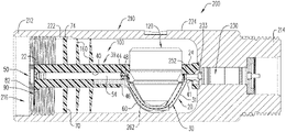
- FIG. 9 is a partial cross-sectional, side view of the perforating gun module of FIG. 8 , illustrating a through wire extending from a detonator to a bulkhead assembly;
- FIG. 10 is a partial cross-sectional, side view of a perforating gun module including a positioning device and a detonator positioned therein, according to an embodiment
- FIG. 11 is a partial cross-sectional, side view of a perforating gun module including a positioning device and a detonator positioned in the first positioning device and an adjacent positioning device including a detonation extender, according to an embodiment;
- FIG. 12 A is a top down view of a housing of a perforating gun module, according to an embodiment
- FIG. 12 B is a top down view of the perforating gun module of FIG. 12 A , illustrating a positioning device therein;
- FIG. 13 A is a perspective view of a resulting mass formed from the detonation of shaped charges positioned in a positioning device, according to an aspect
- FIG. 13 B is a top down view of the perforating gun module of FIG. 12 B , illustrating a resulting mass formed upon detonation of the shaped charges positioned in the positioning device;
- FIG. 14 is a perspective view of a ground member couplable to a positioning device, according to an embodiment
- FIG. 15 is a partial cross-sectional side view of a string of perforating gun modules, according to an embodiment
- FIG. 16 A is a partial cross-sectional perspective view of a string of perforating gun modules configured according to FIG. 10 ;
- FIG. 16 B is a partial cross-sectional perspective view of the string of perforating gun modules of FIG. 16 A , illustrating a ground member positioned in each perforating gun module;
- FIG. 17 is a partial cross-sectional side view of the string of the perforating gun modules configured according to FIG. 11 ;
- FIG. 18 is a perspective view of a positioning device, illustrating a shaped charge positioned in a shaped charge receptacle, according to an embodiment
- FIG. 19 is a perspective view of a positioning device, according to an embodiment.
- FIG. 20 is a front view of a positioning device, illustrating a shaped charge positioned in a shaped charge receptacle, according to an embodiment
- FIG. 21 is a side view of a positioning device, illustrating a shaped charge positioned in a shaped charge receptacle, according to an embodiment
- FIG. 22 is a side, cross-sectional view of the positioning device taken along line B-B of FIG. 20 ;
- FIG. 23 is a top view of a positioning device, illustrating a shaped charge positioned in a shaped charge receptacle, according to an embodiment
- FIG. 24 is a cross-sectional view of the positioning device taken along lines C-C of FIG. 23 ;
- FIG. 25 is a bottom view of a positioning device, illustrating a shaped charge positioned in a shaped charge receptacle, according to an embodiment
- FIG. 26 is a cross-sectional side view of a positioning device, illustrating a shaped charge positioned in a shaped charge receptacle, according to an embodiment
- FIGS. 27 A-C are perspective views of a positioning device, according to an embodiment
- FIG. 28 is a partial cross-sectional side view of a perforating gun module, illustrating a positioning device therein, according to an embodiment
- FIG. 29 is a partial cross-sectional perspective view of a perforating gun module, illustrating a positioning device therein, according to an embodiment
- FIG. 30 is a partial cross-sectional perspective view of a perforating gun module, illustrating a positioning device therein, according to an embodiment
- FIG. 31 is a partial cross-sectional side view of a perforating gun module, illustrating a positioning device therein, according to an embodiment
- FIG. 32 is a partial cross-sectional top view of a perforating gun module, illustrating a positioning device therein, according to an embodiment
- FIG. 33 is a partial cross-sectional side view of a perforating gun module, illustrating a positioning device therein, according to an embodiment
- FIG. 34 is a partial cross-sectional top view of a perforating gun module, illustrating a positioning device therein, according to an embodiment
- FIG. 35 is a partial cross-sectional perspective view of a string of perforating gun modules configured according to FIG. 29 ;
- FIG. 36 is a perspective view of a plurality of perforating gun modules, according to an embodiment.
- the term “energetically” may refer to a detonating/detonative device that, when detonated/or activated, generates a shock wave impulse that is capable of reliably initiating an oilfield shaped charge, booster or section of detonating cord to a high order detonation.
- pressure bulkhead and “pressure bulkhead structure” shall be used interchangeably, and shall refer to an internal, perforating gun housing compartment of a select fire sub assembly. In an embodiment, it also contains a pin assembly and allows the electrical passage of a wiring arrangement.
- the bulkhead structures may include at least one electrically conductive material within its overall structure.
- FIGS. 1 - 2 illustrate a positioning device 10 configured for arranging a plurality of shaped charges 120 ( FIG. 6 ) in a selected configuration.
- the shaped charges 120 may be positioned in an XZ-plane, in an outward, radial arrangement, about a Y-axis of the shaped charge holder 20 ; the Y-axis in the figures is the central axis of the shaped charge holder 20 .
- the positioning device 10 may be configured as a unitary structure formed from a plastic material. According to an aspect, the positioning device 10 is formed from an injection molded material, a casted material, a 3D printed or 3-D milled material, or a machine cut solid material. Upon detonation of the shaped charges 120 positioned in the shaped charge holder 20 , the positioning device may partially melt/soften to capture any shrapnel and dust generated by the detonation.
- the positioning device 10 includes a first end 22 and a second end 24 , and a shaped charge holder 20 extending between the first and second ends 22 , 24 .
- the shaped charge holder 20 includes a plurality of shaped charge receptacles 30 .
- the receptacles 30 are arranged between the first and second ends 22 , 24 of the positioning device 10 .
- the shaped charge receptacles 30 may be radially arranged in the XZ-plane about the Y-axis, i.e., central axis, of the shaped charge holder 20 , each being configured to receive one of the shaped charges 120 .
- the shaped charge receptacles 30 may include a depression/recess 32 that extends inwardly into the positioning device 10 .
- An opening/slot 34 is formed in the depression 30 .
- the opening 34 is configured to facilitate communication between contents of the depression 32 (i.e., the shaped charges 120 ) and a detonative device that extends through the positioning device 10 .
- the opening 34 of each of the shaped charge receptacles 30 , and the shaped charges 120 is spaced from about 60° to about 120° from each other.
- the shaped charge receptacles 30 may be spaced apart from each other equidistantly, which may aid in reducing the formation breakdown pressure during hydraulic fracturing.
- the positioning device 10 may include 2, 3, 4, 5, 6 or more receptacles 30 , depending on the needs of the application.
- the shaped charge receptacles 30 may be configured to receive shaped charges 120 of different configurations and/or sizes.
- the geometries of the perforating jets and/or perforations (holes or perforating holes) that are produced by the shaped charges 120 upon detonation depends, at least in part, on the shape of the shaped charge case, the shape of the liner and/or the blend of powders included in the liner.
- the geometries of the perforating jets and holes may also depend on the quantity and type of explosive load included in the shaped charge.
- the shaped charges 120 may include, for example, substantially the same explosive gram weight, the interior surface of the shaped charge case and/or the design of the liner may differ for each shaped charge 120 in order to produce differently sized or shaped perforations.
- the receptacles 30 are configured to receive at least one of 3 g to 61 g shaped charges. It is contemplated, for example, that the receptacles may be sized to receive 5 g, 10 g, 26 g, 39 g and 50 g shaped charges 120 . Adjusting the size of the shaped charges 120 (and thereby the quantity of the explosive load in the shaped charges 120 ) positioned in the shaped charge receptacles 30 may impact the size of the entrance holes/perforations created in a target formation upon detonation of the shaped charges 120 .
- the positioning device 10 may include three (3) shaped charges receptacles 30 , with a shaped charge 120 being positioned in each receptacle 30 .
- three (3) perforating holes having an equal entrance hole diameter of an amount ranging from about 0.20 inches to about 0.55 inches are formed. To be sure, the equal entrance hole diameter of the perforations will include a deviation of less than 10%.
- three specially designed shaped charges 120 each including 10 g of explosive load, may be installed in a positioning device 10 .
- they may perform equivalent to a standard shaped charge carrier that has three standard shaped charges that each include 22.7 g explosive load.
- the enhanced performance of the specially designed shaped charges 120 may be facilitated, at least in part, may the type of explosive powder selected for the explosive load, the shape and constituents of the liner and the contours/shape of the internal surface of the shaped charge case.
- the combined surface area of the hole diameters may be equivalent to the total surface area that would be formed by an arrangement of 2, 4, 5, 6 or more standard shaped charges of a standard perforating gun.
- the ability of the shaped charge receptacles 30 to receive shaped charges 120 of different sizes or components helps to facilitate a shot performance that is equivalent to that of a traditional shaped charge carrier including 2, 4, 5, 6 or more shaped charges.
- the total surface area of the perforations i.e., the area open to fluid flow
- This may facilitate a cost-effective and efficient way of adjusting the optimal flow path for fluid in the target formation, without modifying the arrangement or quantity of the receptacles 30 .
- the positioning device 10 includes one or more mechanisms that help to guide and/or secure the shaped charges within the shaped charge receptacles 30 .
- the positioning device 10 may include a plurality of shaped charge positioning blocks/bars 85 outwardly extending from the shaped charge holder 20 .
- the positioning blocks 85 may help to guide the arrangement, mounting or placement of the shaped charges 120 within the shaped charge receptacles 30 .
- the positioning blocks 85 may be contoured to correspond to a general shape of the shaped charges 120 , such as conical or rectangular shaped charges. According to an aspect, the positioning blocks 85 provides added strength and stability to the shaped charge holder 20 and helps to support the shaped charges 120 in the shaped charge holder 20 .
- the positioning device 10 further includes a plurality of retention mechanisms 80 outwardly extending from the holder 20 .
- the retention mechanisms 80 may be adjacent each of the shaped charge receptacles 30 .
- the retention mechanisms 80 may be arranged in a spaced apart configuration from each other.
- Each retention mechanism 80 may be adjacent one shaped charge positioning block 85 .
- a pair of the retention mechanisms 80 may flank or be in a sandwich-type configuration with a shaped charge positioning block 85 .
- each member of a pair of the retention mechanisms 80 is spaced apart from each other at a 180° angle, with a shaped charge positioning block (not shown in FIG. 8 ) between each retention mechanism 80 .
- each member of a pair of the retention mechanisms 80 may be spaced at about a 90° degree angle from an adjacent retention mechanism 80 .
- the pair of retention mechanisms 80 may be configured to retain one of the shaped charges 120 within one shaped charge receptacle 30 .
- the retention mechanisms 80 may each include an elongated shaft 81 , and a hook 83 that extends outwardly from the elongated shaft.
- the hook 83 is at least partially curved to engage with a cylindrical wall of the shaped charges 120 , thereby helping to secure the shaped charge 120 within its corresponding shaped charge receptacle 30 , and thus the shaped charge holder 20 .
- the depression 32 of the shaped charge receptacles 30 in combination with at least one of the retention mechanisms 80 and the shaped charge positioning blocks 85 , aid in mechanically securing at least one of the shaped charges 120 within the positioning device 10 .
- An elongated cavity/lumen 40 extends through the positioning device 10 , from the first end 22 to the second end 24 .
- the elongated cavity 40 may be centrally located within the positioning device 10 and is adjacent each of the shaped charge receptacles 30 , and thereby the shaped charge 120 housed in the receptacles 30 .
- the elongated cavity 40 may be configured for receiving and retaining a detonative device therein.
- the detonative device includes a detonator 50 ( FIG. 11 ).
- the detonator 50 may be positioned centrally within the shaped charge holder 20 .
- the plurality of shaped charges 120 housed in the shaped charge holder 20 includes an open front end 320 and a back wall 330 having an initiation point 331 extending therethrough.
- the detonator 50 is substantially adjacent the initiation point 331 and is configured to simultaneously initiate the shaped charges 120 in response to an initiation signal, such as a digital code.
- the detonator 50 is a wireless push-in detonator. Such detonators are described in U.S. Pat. Nos. 9,605,937 and 9,581,422, both commonly owned and assigned to DynaEnergetics GmbH & Co KG, each of which is incorporated herein by reference in its entirety.
- the detonator 50 includes a detonator head 52 and a detonator body 54 ( FIG. 11 ) extending from the detonator head 52 .
- the detonator head 52 includes an electrically contactable line-in portion, an electrically contactable line-out portion, and an insulator positioned between the line-in and line-out portions, wherein the insulator electrically isolates the line-in portion from the line-out portion.
- the detonator body 54 may be energetically coupled to or may energetically communicate with each of the shaped charges 120 .
- the detonator body 54 may include a metal surface, that provides a contact area for electrically grounding the detonator 50 .
- the positioning device 10 may include passageways 28 that help to guide a feed through/electrical wire 260 ( FIG. 9 ) from the detonator 50 to contact a bulkhead assembly/pressure bulkhead assembly 230 ( FIG. 9 ). As illustrated in FIGS. 1 - 2 and FIG. 11 , the passageway 28 may be formed at the second end 24 of the positioning device 10 and receives and guides the feed through wire/electrical wire 260 to the bulkhead assembly 230 .
- the positioning device 10 may be configured as a modular device having a plurality of connectors 26 that allows the positioning device 10 to connect to other adjacent positioning devices, adjacent shaped charge holders, and spacers, as illustrated in FIG. 4 .
- the positioning device 10 may be configured to engage or connect to charge holders, spacers and connectors described in U.S. Pat. Nos. 9,494,021 and 9,702, 680, both commonly owned and assigned to DynaEnergetics GmbH & Co KG, each of which is incorporated herein by reference in its entirety.
- the connectors 26 each extend along the central Y-axis of the shaped charge holder 20 .
- the connectors 26 includes at least one of a plurality of plug connectors/pins 27 a and a plurality of receiving cavities/sockets 27 b .
- the plurality of receiving cavities/sockets 27 b are shown in FIG. 1 and FIG. 2 on the opposite end of the positioning device 10 , for receiving plug connectors 27 a from a downstream positioning device.
- the plug connectors 27 a outwardly extend from the first or second end 22 , 24 , and the receiving cavities 27 b inwardly extend into the positioning device 10 from the first or second end 22 , 24 .
- the plug connectors 27 a are configured for being inserted and at least temporarily retained into the receiving cavities 27 b of the adjacent positioning device, shaped charge holder, spacer or other connectors, while the receiving cavities 27 b are configured to receive plug connectors 27 a of another adjacent positioning device, charge holder, spacer or other components.
- the first end 22 includes plug connectors 27 a
- the second end 24 includes receiving cavities 27 b that are configured to receive and retain the plug connectors of the adjacent positioning device, charge holder, spacer or other components.
- the plug connectors 27 a are mushroom-shaped, which may aid in the retention of the plug connectors 27 a in the receiving cavities.
- FIGS. 3 - 5 and 8 - 11 Further embodiments of the disclosure are associated with a positioning device 110 , as illustrated in FIGS. 3 - 5 and 8 - 11 .
- the positioning device 110 includes a first end 22 and a second end 24 .
- the first end 22 of the positioning device 110 may be contoured to retain a detonator head 52 ( FIG. 8 and FIG. 12 B ) therein.
- a shaped charge holder 20 extends between the first and second ends 22 , 24 of the positioning device 110 .
- the general characteristics of the shaped charge holder 20 applicable to the positioning device 110 are described above with respect to the FIGS. 1 - 2 , and are not repeated here.
- the shaped charge holder 20 illustrated in FIG. 3 includes a plurality of shaped charge receptacles 30 , a plurality of retention mechanisms 80 and a plurality of positioning blocks 85 , which are configured substantially as described hereinabove with respect to FIGS. 1 - 2 and FIGS. 8 - 9 .
- the features and characteristics of the receptacles 30 , the retention mechanisms 80 and the positioning blocks 85 of the positioning device 110 are not repeated here.
- the positioning device 110 further includes an elongated cavity/lumen 40 extending through a length of the positioning device 110 .
- the elongated cavity 40 extends from the first end 22 to the second end 24 , adjacent each of the shaped charge receptacles 30 , and is configured for receiving and retaining a detonator 50 .
- FIG. 10 illustrates the detonator 50 positioned in the elongated cavity 40 .
- the detonator 50 is configured to initiate the shaped charges 120 simultaneously in response to an initiation signal.
- the detonator 50 may be a wireless push-in detonator.
- the detonator 50 of the positioning device 110 may be configured substantially as the detonator 50 of the positioning device 10 described hereinabove with respect to FIGS. 1 - 2 , thus for purposes of convenience and not limitation, the various features of the detonator 50 for the positioning device 10 are not repeated hereinbelow.
- the detonator 50 of the positioning device 110 includes a detonator head 52 and a detonator body 54 is energetically coupled to each of the shaped charges 120 .
- the elongated cavity 40 may be stepped or contoured to receive the head 52 and body 54 of the detonator 50 .
- the elongated cavity 40 includes a first cavity 42 and a second cavity 44 extending from the first cavity 42 .
- the first cavity 42 extends from and is adjacent the first end 22 of the positioning device 110 , while the second cavity 44 extends from the first cavity 42 towards the second end 24 .
- the first cavity 42 is larger than the second cavity 44 and is configured for receiving the detonator head 52 , while the second cavity 44 is configured for receiving the detonator body 54 .
- the positioning device 110 is be equipped with means for maintaining the positioning device 110 in a preselected position in a perforating gun module 200 .
- the positioning device 110 may include at least one rib/fin 160 outwardly extending from the positioning device 110 .
- FIG. 3 illustrates ribs 160 radially extending from the positioning device 110 and being arranged between the first end 22 of the positioning device 110 and the shaped charge holder 20 .
- the ribs 160 may be substantially equal in length with each other and may be configured to engage with an interior surface of a perforating gun module 200 , as illustrated in, for example, FIGS. 8 - 11 .
- the positioning device 110 may further include a plate 70 at least partially extending around the positioning device 110 .
- the plate 70 may be disposed/arranged between the first end 22 and the rib 160 .
- FIG. 3 illustrates a protrusion/anti-rotation key 74 extending from a peripheral edge 72 of the plate 70 .
- the anti-rotation key 74 may be configured to secure the positioning device 110 within a perforating gun module 200 , and to prevent rotation of the positioning device 110 and the shaped charge holder 20 within the perforating gun module 200 . As illustrated in FIGS. 8 - 11 and FIG.
- the anti-rotation key 74 may be configured to engage with an inner surface 220 (or a slot 222 ) of a housing 210 of the perforating gun module 200 , which helps ensure that the shaped charges 120 are maintained in their respective positions with respect to the perforating gun module 200 .
- the plate 70 is sized and dimensioned to capture debris resulting from detonation of the plurality of shaped charges 120 . As illustrated in FIG.
- the plate 70 has a larger surface area than the ribs 160 , such that it is able to collapse with at least one of the shaped charge holder 20 and the ribs 160 , and capture any debris generated by the detonation of the shaped charges 120 , thereby reducing the amount (i.e., number of individual debris) that may need to be retrieved from the wellbore.
- the positioning device 110 further includes a disk 25 outwardly and circumferentially extending from the positioning device 110 .
- the disk is arranged between the first end 22 and the plate 70 and, as illustrated in FIG. 8 and FIG. 9 , may help to create an isolation chamber 280 for the detonator head 52 .
- the isolation chamber 280 may protect and isolate the detonator 50 from loose metallic particles, shards, machine metal shavings and dust, or substantially minimize the detonator head 52 from such exposure, that may negatively impact the functionality of the detonator 50 and cause an electrical short circuit in the system.
- one or more components of the positioning device 110 may be configured with a passageway 28 .
- the passageway 28 may be formed in at least one of the disk 25 ( FIG. 12 B ), the plate 70 ( FIG. 12 B ) and the second end 24 ( FIGS. 3 - 4 ) of the body 20 .
- the passageway 28 receives and guides a feed through wire/electrical wire 260 from the detonator 50 to the second end of the positioning device 110 , wherein the wire 260 contacts a bulkhead assembly/rotatable bulkhead assembly 230 .
- a ground member 90 may be arranged on or otherwise coupled to the positioning device 110 .
- the ground member 90 is secured to the positioning device 110 , between the first end 22 and the plate 70 .
- a support member 82 extends from the positioning device 110 , between the ground member 90 and the plate 70 .
- the support member 82 is configured to prevent movement of the ground member 90 along the central Y-axis of the shaped charge holder 20 , to ensure that the ground member 90 is able to contact a portion of an adjacent perforating gun module.
- FIG. 14 shows the ground member 90 in more detail.
- the ground member 90 may include a centrally-arranged opening 92 having a plurality of engagement mechanisms 93 , and one of more slots 94 to facilitate the ground member 90 being secured to the positioning device 110 and to facilitate the engagement of the ground member 90 with the adjacent perforating gun module.
- the ground member 90 is formed from a stamped, laser cut, or water-jet cut sheet of metal.
- the ground member 90 may be formed from at least one of stainless steel, brass, copper, aluminum or any other electrically conductive sheeted material which can be stamped and re-worked, water jet cut or laser cut.
- the positioning device 110 may be connectable to adjacent devices or components of a perforating gun module 200 .
- at least one of the first end 22 and the second end 24 includes a plurality of connectors 26 extending along the central Y-axis of the charge holder 20 .
- the connectors 26 provide for a modular connection between the positioning device 110 and at least one of an adjacent positioning device, an adjacent shaped charge holder and a spacer including corresponding connectors.
- the connectors 26 of the positioning device 110 may be configured substantially as the connectors 26 of the positioning device 10 described hereinabove with respect to FIGS. 1 - 2 , thus for purposes of convenience and not limitation, the various features of the connectors 26 of the positioning device 10 are not repeated here.
- the shaped charges 120 is a first set of shaped charges, and a second set of shaped charges 120 ′ is supported in a separate shaped charge holder 20 ′ connected to the positioning device 110 .
- the separate shaped charge holder 20 ′ may be included in the positioning device 10 illustrated in FIGS. 1 - 2 .
- the separate shaped charge holder 20 ′ includes a plurality of shaped charge receptacles 30 extending between first and second ends 22 , 24 of the separate shaped charge holder 20 ′.
- the receptacles 30 are radially arranged in an XZ-plane about a central Y-axis of the separate shaped charge holder 20 ′, each receptacle 30 retaining one of the shaped charges 120 ′.
- An elongated cavity 40 extends from the first end 22 to the second end 24 of the separate shaped charge holder 20 ′ and is configured for retaining a detonation extender 55 therein.
- the detonation extender 55 includes a detonating cord or a booster device 56 .
- the detonation extender 55 is configured to abut an end of the detonator body 54 and extend from the elongated opening 40 of the positioning device 110 into the elongated opening 40 of the separate shaped charge holder 20 ′ so the detonator extender is adjacent initiation points 331 of the separate shaped charges 120 ′.
- the detonation extender 55 is adjacent a plurality of openings 34 formed in the shaped charge receptacles of the separate shaped charge holder 20 ′.
- a detonation energy from the detonator 50 simultaneously activates the shaped charges 120 of the first set of shaped charges and the detonation extender 55 .
- the detonation extender 55 thereafter generates a detonation wave, which simultaneously activates the second set of shaped charges 120 ′.
- the positioning device 110 and the separate charge holder 20 ′ forms a resulting mass 111 ( FIGS. 13 A- 13 B ) and limits the amount of debris generated upon detonation of the shaped charges
- a shaped charge 120 for use at least one of a positioning device 110 and a shaped charge holder 20 includes a substantially cylindrical/conical case 310 .
- the conical case 310 includes an open front end 320 , a back wall 330 having an initiation point 331 extending therethrough, and at least one cylindrical side wall 340 extending between the open front end 320 and the back wall 330 .
- the shaped charge 120 further includes a cavity 322 defined by the side wall 340 and the back wall 330 .
- An explosive load 324 is disposed within the cavity 322 .
- the explosive load 324 includes at least one of pentaerythritol tetranitrate (PETN), cyclotrimethylenetrinitramine (RDX), octahydro-1,3,5,7-tetranitro-1,3,5,7-tetrazocine/cyclotetramethylene-tetranitramine (HMX), 2,6-Bis(picrylamino)-3,5-dinitropyridine/picrylaminodinitropyridin (PYX), hexanitrostibane (HNS), triaminotrinitrobenzol (TATB), and PTB (mixture of PYX and TATB).
- PETN pentaerythritol tetranitrate
- RDX cyclotrimethylenetrinitramine
- the explosive load 324 includes diamino-3,5-dinitropyrazine-1-oxide (LLM-105).
- the explosive load may include a mixture of PYX and triaminotrinitrobenzol (TATB).
- TATB triaminotrinitrobenzol
- the type of explosive material used may be based at least in part on the operational conditions in the wellbore and the temperature downhole to which the explosive may be exposed.
- a liner 326 is disposed adjacent the explosive load 324 .
- the liner 326 is configured for retaining the explosive load 324 within the cavity 322 .
- the liner 326 has a conical configuration, however, it is contemplated that the liner 326 may be of any known configuration consistent with this disclosure.
- the liner 326 may be made of a material selected based on the target to be penetrated and may include, for example and without limitation, a plurality of powdered metals or metal alloys that are compressed to form the desired liner shape. Exemplary powdered metals and/or metal alloys include copper, tungsten, lead, nickel, bronze, molybdenum, titanium and combinations thereof.
- the liner 326 is made of a formed solid metal sheet, rather than compressed powdered metal and/or metal alloys. In another embodiment, the liner 326 is made of a non-metal material, such as glass, cement, high-density composite or plastic. Typical liner constituents and formation techniques are further described in commonly-owned U.S. Pat. No. 9,862,027, which is incorporated by reference herein in its entirety to the extent that it is consistent with this disclosure.
- the explosive load 324 detonates and creates a detonation wave that causes the liner 326 to collapse and be expelled from the shaped charge 120 .
- the expelled liner 326 produces a forward-moving perforating jet that moves at a high velocity
- the cylindrical side wall portion 340 includes a first wall 342 outwardly extending from a flat surface 332 of the back wall 330 , a second wall 344 outwardly extending from the first wall 342 , and a third wall 346 upwardly extending from the second wall 344 towards the open front end 320 .
- the third wall 346 may be uniform in width as it extends from the second wall 344 to the open front end 320 .
- An engagement member 350 outwardly extends from an external surface 341 of the side wall 340 . As illustrated in FIG. 6 , the engagement member 350 extends from the first wall 342 , at a position adjacent the second wall 344 . As illustrated in FIG. 5 , the engagement member 350 may be configured for coupling the shaped charge 120 within a shaped charge holder 20 of a positioning device 10 / 110 .
- at least one of the first wall 342 and the second wall 344 includes an engagement groove/depression 352 circumferentially extending around the side wall 340 .
- the groove 352 extends inwardly from the side wall 340 of the case 310 towards the cavity 322 .
- the groove 352 may be configured to receive one or more retention mechanisms 80 of the positioning device 10 / 110 or the shaped charge holder 20 , thereby securedly fastening the shaped charge 120 to the positioning device 10 / 110 or the shaped charge holder 20 .
- the size of the shaped charge 120 may be of any size based on the needs of the application in which the shaped charge 120 is to be utilized.
- the conical case 310 of the shaped charge 120 may be sized to receive from about 3 g to about 61 g of the explosive load 324 .
- the caliber/diameter of the liner 326 may be dimensioned based on the size of the conical case 310 and the explosive load 324 upon which the liner 326 will be disposed.
- the arrangement of the shaped charges 120 in the positioning device 10 / 110 may provide the equivalent shot performance (and provide equivalent fluid flow) of a typical assembly/shot carrier having 4, 5, 6 shaped charges.
- Embodiments of the disclosure are further associated with a perforating gun module 200 .
- the perforating gun module 200 includes a housing/sub assembly/one-part sub 210 formed from a preforged metal blank/shape.
- the housing 210 may include a length L 1 of less than about 12 inches, alternatively less than about 9 inches, alternatively less than about 8 inches. According to an aspect, the length of the housing 210 may be reduced because the perforating gun module 200 does not require the use of separate tandem sub adapters to connect or seal a plurality of perforating gun modules 200 .
- the housing 210 includes a first housing end 212 , a second housing end 214 , and a chamber 216 extending from the first housing end 212 towards the second housing end 214 .
- the housing 210 may be configured with threads to facilitate the connection of a string of perforating gun modules 200 together.
- an inner surface 220 of the housing 210 at the first housing end 212 includes a plurality of internal threads 221 a
- an outer/external surface 224 of the housing 210 includes a plurality of external threads 221 b at the second housing end 214 .
- a plurality of housings 210 may be rotatably connected to each other via the threads 221 a , 221 b .
- a plurality of sealing mechanisms such as o-rings 270 may be used to seal the housing 210 of the perforating gun module 200 from the contents of the housing of an adjacent perforating gun, as well as from the outside environment (fluid in the wellbore) from entering the chamber 216 .
- the first housing end 212 has a first width W 1
- the second housing end 214 has a second width W 2
- the chamber 216 has an internal diameter ID.
- the second width W 2 may be less than the first width W 1
- the internal diameter ID of the chamber 216 may be substantially the same as the second width W 2 .
- the second housing end 214 of the housing 210 of the perforating gun module 200 may be rotatably secured within the first housing end 212 (i.e., in the chamber) of the housing of an adjacent perforating gun module 200 ′.
- the second housing end 214 is configured to be secured within a chamber of an adjacent perforating gun assembly 200 ′
- the first housing end 212 is configured to secure a second housing end of another adjacent perforating gun module.
- one or more positioning devices 10 / 110 may be secured in the chamber 216 of the housing 210 .
- the positioning device 10 / 110 may be configured substantially as described hereinabove and illustrated in FIGS. 1 - 5 . Thus, for purposes of convenience, and not limitation, the features and functionality of the positioning device 10 / 110 are not repeated in detail herein below.
- the first end 22 of the positioning device 110 is adjacent the first housing end 212 .
- the rib 160 of the device 110 engages with an inner surface 220 of the housing 210 , within the chamber 216 , thereby preventing the device from moving upwardly or downwardly in the chamber 216 .
- a plate 70 of the positioning device 110 helps to further secure the positioning device 110 in the housing 210 .
- the plate 70 includes an anti-rotation key 74 extending from a peripheral edge 72 of the plate 70 .
- the anti-rotation key 74 may be seated in a slot 222 formed in an inner surface 220 of the housing 210 .
- FIG. 7 illustrates the slot extending from the first housing end 212 into the chamber 216 .
- the anti-rotation key 74 of the plate 70 engages the slot 222 to secure the positioning device 110 within the perforating gun 200 and prevent unwanted rotation of the positioning device 110 , and thus the shaped charge holder 20 , within the perforating gun module 200 .
- the plate 70 and the shaped charge holder 20 is configured to capture debris resulting from detonation of the shaped charges 120 .
- the captured debris, the plate 70 and the shaped charge holder 20 forms a mass/resulting mass 111 ( FIG. 13 A ) upon the detonation of the charges 120 .
- the resulting mass 111 is retained in the chamber 216 of the housing 210 .
- the resulting mass 111 includes shrapnel and debris created upon the detonation of the shaped charges, as well as any additional wires (e.g. through wire 260 ) or components previously placed or housed in the housing 210 .
- the housing 210 further includes a recess/mortise 218 extending from the second housing end 214 towards the chamber 216 .
- the recess 218 partially tapers from the second housing end 214 towards the chamber 216 .
- a varying depth bore 217 shown in FIG. 7 , extends from the chamber 216 to connect the chamber 216 with the recess 218 .
- the bore 217 is configured to sealingly receive and engage a bulkhead assembly 230 in a sealed position (shown, for example, in FIG. 28 ).
- the chamber 216 is configured to house the detonator head 52 of a detonator 50 of an adjacent positioning device 110 . As illustrated in FIG.
- the disk 25 of the positioning device 110 of an adjacent perforating gun module 200 covers a portion of the recess 218 , thereby forming an isolation chamber 280 for the detonator head 52 .
- the recess 218 may include a length L 2 of less than about 2 inches.
- a bulkhead assembly 230 may be positioned in the varying depth bore 217 , between the chamber 216 (i.e., adjacent the second end 24 of the positioning device 110 ) and the recess 218 .
- the bulkhead assembly 230 is a rotatable bulkhead assembly.
- Such bulkhead assemblies are described in U.S. Pat. No. 9,784,549, commonly owned and assigned to DynaEnergetics GmbH & Co KG, which is incorporated herein by reference in its entirety.
- the bulkhead assembly 230 includes a bulkhead body 232 having a first end 233 and a second end 234 .
- a metal contact plug/metal contact 250 is adjacent the first end 233 of the bulkhead body 232 and a downhole facing pin 236 extends from a second end 234 of the bulkhead body 232 .
- the perforating gun module 200 further includes a feed through wire 260 extending from the detonator 50 to the metal contact plug 250 via the line-out portion of the detonator head 52 .
- the metal contact plug 250 is configured to secure the feed through wire 260 to the first end 233 of the bulkhead assembly 230 .
- the metal contact plug 250 provides electrical contact to the bulkhead assembly 230 , while the downhole facing pin 236 is configured to transfer an electrical signal from the bulkhead assembly 230 to a detonator 50 ′ of the adjacent perforating gun module 200 ′.
- FIGS. 8 - 11 illustrate a collar 240 secured within the recess 218 .
- the collar 240 is adjacent the second end 234 of the bulkhead assembly 230 .
- the collar 240 includes external threads 242 ( FIG. 10 ) configured for engaging with or being rotatably secured in the recess 218 of the housing 210 .
- the bulkhead assembly 230 is also thereby secured in the housing 210 .
- the ground members 90 secured to the positioning devices 110 engage with the inner surface 220 housing 210 to provide a secure and reliable electrical ground contact from the detonator 50 ′ (see FIG. 9 ), and also contacts the second end portion 214 of the adjacent perforating gun modules 200 .
- the support members 82 of each of the positioning devices 110 of the perforating gun modules 200 may prevent movement of the ground member 90 along the central Y-axis of the shaped charge holder 20 and help to facilitate the contact of the ground member 90 with the second end portion of the adjacent perforating gun module 200 ′.
- FIGS. 15 , 16 A and 16 B illustrate the perforating gun modules 200 each including one positioning device 110
- perforating gun modules may be configured to receive more than one positioning device 110 , or the positioning device 10 of shaped charge holder 20 described hereinabove with respect to FIGS. 1 - 2 .
- FIG. 17 illustrates an embodiment in which the positioning device 110 of FIG. 3 is coupled to the positioning device 10 or a separate shaped charge holder 20 of FIGS. 1 - 2 and are coupled together and secured in a housing 210 of a perforating gun module 200 .
- the elongated cavity 40 of the separate shaped charge holder 20 ′ retains a detonation extender 55 .
- the detonation extender 55 extends from the elongated opening of the positioning device 110 into the elongated opening of the separate shaped charge holder 20 ′.
- the detonation energy from the detonator 50 simultaneously activates the shaped charges 120 of the first set of shaped charges and activates the detonation extender 55
- a detonation wave from the detonation extender 55 simultaneously activates the second set of shaped charges 120 ′ retained in the shaped charge holder 20 ′ or separate positioning device 10 .
- the single-charge positioning device 100 may be formed of a unitary piece of molded material, such as injection molded plastic.
- the single-charge positioning device 100 is configured for securing and positioning a single shaped charge 120 within a perforating gun assembly 200 .
- the single-charge positioning device 100 is shown in FIGS. 18 - 27 C . As shown in FIG. 18 , the single-charge positioning device 100 has a first end 22 and a second end 24 . A detonator holder 39 and a shaped charge holder 20 extends between the first end 22 and second end 24 . According to an aspect, the detonator holder 39 is formed between the first end 22 and the shaped charge holder 20 , and the shaped charge holder 20 is formed between the detonator holder 39 and the second end 24 .
- the detonator holder 39 receives and retains a detonative device (such as a detonator 50 , described hereinabove with respect to the positioning device 110 and illustrated in, e.g., FIG. 11 ).
- the detonator holder 39 includes an elongated cavity 40 having at least a first cavity 42 sized for receiving a detonator head 52 and a second cavity 44 sized for receiving a detonator body 54 .
- a detonating cord channel 46 ( FIG. 28 ) is arranged in a side-by-side configuration adjacent at least a portion of the second cavity 44 and extends towards the shaped charge holder 20 .
- the detonating cord channel 45 and/or detonating cord 60 may be configured face-to-face with the the detonator 50 /second cavity 44 , or in any other configuration consistent with this disclosure.
- the detonating cord channel 46 is formed partially within a pair of arms 33 within the recess 32 of the shaped charge receptacle 30 as shown in, e.g., FIGS. 19 , 22 , 25 and 26 .
- the detonating cord channel 46 extends from the shaped charge receptacle 30 (where, in use, it may communicate ballistically with a shaped charge 120 secured in the shaped charge receptacle 30 ) to a location adjacent the elongated cavity 40 of the detonator holder 39 , so that it is also in ballistic communication with the detonator 50 within the elongated cavity 40 .
- the detonating cord channel 46 as illustrated in FIG.
- the detonator 22 is configured to receive and secure a detonating cord 60 or similar ballistic device in contact both with a portion of the detonator 50 (for example, an outer surface of the detonator body 54 ) and with an initiation point 331 located on a base/closed back wall 330 of the shaped charge 120 (see FIGS. 23 - 24 ).
- a detonating cord 60 is initiated by an initiation signal, for example, a digital code
- the detonating cord 60 is ignited and in turn initiates the shaped charge 120 via ballistic or thermal transfer at the initiation point 331 .
- the detonator 50 is a wireless push-in detonator.
- the length of the detonating cord 60 may vary depending on the particular application, and the detonating cord 60 may be used to connect different or additional ballistic components, such as detonator extenders, boosters, pellets, additional shaped charges, and the like.
- the shaped charge holder 20 is located between the detonator holder 39 and the second end 24 of the positioning device 100 and includes a single shaped charge receiving area/receptacle 30 to receive and hold a single shaped charge 120 .
- the shaped charge receptacle 30 may be configured to receive a shaped charge 120 of various configurations and/or sizes.
- the receptacle 30 is a frame-like/lattice-like structure configured to secure the shaped charge within the charge holder 20 .
- the receptacle 30 may be configured with a frame 31 that receives the closed end of the shaped charge.
- the frame 31 includes arms 33 that are configured to extend around and beneath the case of the shaped charge 120 .
- the single-charge positioning device 100 includes one or more mechanisms to guide and/or secure the shaped charge 120 within the shaped charge holder 20 .
- Exemplary mechanisms as shown in FIG. 18 and FIG. 19 may include a plurality of shaped charge retention mechanisms 80 and/or shaped charge positioning blocks/bars 85 configured to mechanically secure the shaped charge 120 within the shaped charge holder 20 .
- the retention mechanisms 80 and the positioning blocks 85 may be arranged about the frame 31 of the shaped charge receptacle 30 at least in part based on the configuration of the shaped charge 120 that will be positioned therein. While an exemplary shaped charge 120 is illustrated in FIG. 6 , for example, other shaped charge configurations are contemplated.
- the retention mechanisms 80 each include an elongated shaft 81 extending from the frame 31 of the receptacle 30 , with a hook 83 located on an upper extremity of the elongated shaft 81 .
- a hook 83 located on an upper extremity of the elongated shaft 81 .
- at least a portion of the elongated shaft 81 extends radially inwardly from the frame 31 and is connected to an arm 33 of the receptacle 30 , such that the elongated shaft 81 helps to support the single shaped charge 120 in the receptacle 30 .
- At least a portion of the elongated shaft 81 may extend upwardly and generally perpendicularly to the arm 33 , such that the single shaped charge 120 can be received within the receptacle 30 with at least a portion of the shaped charge 120 protruding from the receptacle 30 and the elongated shaft 81 helps to secure and maintain the position of the protruding portion of the shaped charge 120 .
- the depression/recess 32 in the shaped charge receptacle 30 is defined in part by the arms 33 extending downwardly and radially inwardly from the retention mechanisms 80 and the frame 31 .
- the hooks 83 may be curved or chamfered so as to be able to couple with the corresponding groove 352 and projecting engagement member 350 disposed on the external surface 341 of the side wall 340 of the shaped charge 120 . This may help to securedly engage and retain the shaped charge 120 within the shaped charge receptacle 30 ( FIG. 18 and FIG. 24 ).
- the retention mechanisms 80 and/or positioning blocks/bars 85 of the positioning device 100 may be configured substantially as the retention mechanisms 80 and/or positioning blocks/bars 85 of the positioning device 10 / 110 described hereinabove with respect to FIGS. 1 - 3 and FIGS. 8 - 9 .
- the positioning blocks/bars 85 may be located adjacent to the shaped charge receptacle 30 .
- one or more of the shaped charge positioning blocks/bars 85 may be offset from one or more of the retention mechanisms 80 (shown, for example, in FIGS. 1 and 19 ).
- a retention mechanism 80 may be disposed on a positioning block 85 such that it is in alignment with, and not radially offset from, the positioning block 85 .
- a hook 83 of a retention mechanism 80 may be disposed on the surface of a positioning block 85 .
- the hook 83 may feature a projecting engagement member 350 configured to engage with a shaped charge groove 352 to aid in securing the shaped charge 120 within the shaped charge receptacle 30 (as shown in FIG. 24 ).
- the shaped charge holder 20 may include within the shaped charge receptacle 30 an annular fastener/clip 354 ( FIG. 22 ).
- the clip 354 extends radially inwardly towards the center of the shaped charge receptacle 30 from at least a portion of the positioning blocks 85 and is located in a position above the hook(s) 83 of the retention mechanisms 80 relative to the shaped charge 120 .
- the clip 354 may engage a shaped charge annular indentation 356 formed on an external surface 341 of the shaped charge 120 , which helps to secure the shaped charge 120 within the positioning device 100 .
- the clip 354 may be of any shape and size and may be positioned on any portion of the shaped charge holder 20 that facilitates securement of the shaped charge 120 within the shaped charge receptacle 30 via engagement with a correspondingly shaped, sized, and positioned annular indentation 356 . According to further embodiments, the clip 354 may be the only engagement means provided to secure the shaped charge 120 in the shaped charge receptacle 30 .
- the clip 354 in various embodiments may extend from one or more of the detontator holder 39 , the receptacle frame 31 , and the second end 24 of the positioning device 100 .
- the shaped charges 120 for use with the aforementioned positioning devices 10 / 110 illustrated in FIGS. 1 - 5 and as described hereinabove with respect to FIG. 6 may be specially configured to be secured in the shaped charge holder 20 of the single-charge positioning device 100 .
- common features as previously described may not be reiterated hereinbelow.
- the shaped charge 120 may include a substantially cylindrical/conical case 310 formed of a conductive material, such as metal.
- the conical case 310 includes an open front end 320 , a back wall 330 having an initiation point 331 extending therethrough, and at least one cylindrical side wall 340 extending between the open front end 320 and the back wall 330 .
- a cavity 322 is defined by the plurality of walls forming the conical case 310 .
- the back wall 330 may include a flat surface 332 for facilitating ballistic communication of the detonating cord 60 with the initiation point 331
- the back wall 330 may additionally or alternatively include an angled upper back wall 330 a (as shown in FIG.
- shaped charge 120 may be modified so as to provide engagement and coupling means with a corresponding annular fastener/clip 354 or retention mechanisms 80 of the shaped charge receptacle 30 , such as annular indentations 356 , grooves 352 or projecting engagement members 350 .
- the single-charge positioning device 100 may be equipped with mechanisms that maintain the single-charge positioning device 100 in a preselected position in a perforating gun module 200 (as seen in, for instance, FIGS. 27 A- 27 B and FIGS. 28 - 35 , discussed in further detail below).
- Such mechanisms may include at least one rib or fin 160 , and a plate 70 having a peripheral edge 72 and anti-rotation key 74 extending from the peripheral edge 72 .
- the rib 160 and the plate 70 of the single-charge positioning device 100 may be configured substantially as the rib 160 and the plate 70 of the single-charge positioning device 110 described hereinabove with respect to FIG. 3 .
- common features as previously described may not be reiterated hereinbelow.
- the rib 160 extends outwardly from the single-charge positioning device 100 between the first end 22 and the shaped charge holder 20 and is configured to engage with an inner surface 220 of a perforating gun housing 210 to prevent the single-charge positioning device from moving upwardly or downwardly within the perforating gun housing chamber 216 .
- the plate 70 at least partially extends around the single-charge positioning device 100 between the first end 22 and the rib 160 , as shown in FIG. 28 .
- the plate 70 includes an anti-rotation key 74 extending from a peripheral edge 72 of the plate 70 .
- the anti-rotation key 74 is shaped and sized to engage a slot 222 formed in an inner surface 220 of the housing 210 , to orient the single-charge positioning device 100 and the shaped charge 120 within the perforating gun module 200 and prevent rotation of the single-charge positioning device 100 within the perforating gun module 200 .
- a recessed portion/depression/divot/scallop 244 may be formed in the outer circumferential surface 224 of the housing 210 such that a portion of the wall of the gun housing 210 at the location of the scallop 244 is thinner than portions of the wall of the gun housing 210 adjacent to the scallop 244 . According to an aspect, the scallop 244 is radially aligned with the slot 222 .
- Embodiments of the disclosure are further associated with the perforating gun module 200 ( FIGS. 28 - 35 ) having the housing 210 and the single-charge positioning device 100 arranged in the housing 210 .
- the general characteristics of the perforating gun module 200 for housing the positioning device 110 or the charge holders 20 described hereinabove with respect to the FIGS. 7 - 11 are applicable to the positioning device 100 .
- those specific corresponding features and function are not repeated hereinbelow.
- the single-charge positioning device 100 includes a support member 82 configured to support or engage a portion of a grounding device, such as a ground member 90 .
- the support member 82 extends from the single-charge positioning device 100 , at a location between the first end 22 and the plate 70 .
- the ground member 90 and the support member 82 of the positioning device 100 are configured substantially as the ground member 90 and support member 82 of the positioning device 10 / 110 described hereinabove with respect to FIGS. 8 - 11 and FIG. 12 B , and are configured to contact a second end portion of an adjacent perforating gun module to provide secure and reliable electrical ground contact from the detonator 50 .
- the ground member 90 is described in further detail hereinabove, and is illustrated in detail in FIG. 14 . Thus, for purposes of convenience and not limitation, the support member 82 and the ground member 90 are not described hereinbelow.
- the single-charge positioning device 100 may be configured as a modular device having a plurality of connectors that allow the single-charge positioning device 100 to connect to other adjacent positioning devices, adjacent shaped charge holders, adjacent spacers, and other like components.
- Such connectors may extend from at least one of the first end 22 and the second end 24 of the single-charge positioning device 100 , and may be configured substantially as the connectors 26 of the positioning device 10 / 110 described hereinabove with respect to FIGS. 1 - 2 .
- the various features of such connectors are not repeated here.
- a plug opening 41 is formed at the second end 24 of the single-charge positioning device 100 .
- the plug opening 41 is configured for receiving an electrically contactable component (such as at least one of a metal plug 250 or a spring-loaded bulkhead pin 252 ) for electrical communication with a bulkhead assembly 230 (shown, for example, in FIG. 28 ).
- the opening 41 facilitates connection between the spring-loaded bulkhead pin 252 and the metal plug 250 .
- the plug opening 41 may include a through-wire passageway 28 to receive a through-wire 260 (see, for example, FIGS. 28 and 30 ).
- the through-wire may extend from a detonator to the bulkhead assembly/pressure bulkhead assembly 230 in order to provide electrical communication with a downstream perforating gun module 200 ′.
- the bulkhead assembly/pressure bulkhead assembly 230 of the single-charge positioning device 100 may be configured substantially as the bulkhead assembly/pressure bulkhead assembly 230 of the positioning device 10 / 110 described hereinabove with respect to FIG. 9 , thus, for purposes of convenience and not limitation, the various features of the bulkhead assembly/pressure bulkhead assembly 230 for the single-charge positioning device 100 are not repeated hereinbelow.
- the bulkhead assembly 230 is positioned between a chamber 216 within the perforating gun housing 210 , and a recess 218 formed between the chamber 216 and a second end 214 of the perforating gun module 200 .
- a varying depth bore 217 is disposed between the chamber 216 and the recess 218 , and houses the bulkhead assembly 230 .
- the varying depth bore 217 is sized to sealingly receive and engage the bulkhead assembly 230 in a sealed position.
- the bulkhead assembly 230 includes a downstream pin 236 extending from a second end 234 of the bulkhead assembly and into the recess 218 .
- a collar 240 may be secured within the recess 218 and adjacent the second end 234 of the bulkhead assembly 230 to aid sealing the bulkhead assembly 230 in the varying depth bore 217 .
- the through-wire 260 of the single-charge positioning device 100 includes an electrically contactable plate (not shown) on a first end 261 and the metal contact plug 250 on an opposite end 263 , as illustrated in FIGS. 28 and 30 .
- the electrically contactable plate is in electrical communication with an electrically contactable line-out portion of the detonator 50 (for example, a portion of the detonator head 52 ).
- the through-wire 260 travels the length of the single-charge positioning device 100 and is threaded through the through-wire opening 28 so that the metal plug 250 can be positioned in the opening 41 .
- the metal plug 250 is in electrical communication with a spring-loaded bulkhead pin 252 of the bulkhead assembly 230 , so that the feed-through wire may communicate an electrical signal from the detonator 50 to a downstream perforating gun module 200 ′ via the bulkhead assembly 230 .
- no through-wire 260 is needed to provide electrical communication between a detonator 50 and a bulkhead assembly 230 to transmit an electrical signal from an upstream perforating gun module 200 to a downstream perforating gun module 200 ′.
- the detonator 50 is formed of an electrically conductive material to enable electrical communication between the detonator body 54 and the casing 310 of the shaped charge 120 .
- the detonator head 52 includes a line-in portion, a ground portion and an insulator, while the detonator body 54 includes a line-out portion.
- a spring 48 may be in contact with the end of the detonator body 54 and in contact with a case 310 of the shaped charge 120 to ensure reliable contact between the detonator body 54 and the shaped charge casing 310 .
- the spring 48 is compressed by and contacts the detonator body 54 when the detonator 50 is positioned within the elongated cavity/lumen 40 of the detonator holder 39 , and the spring-loaded bulkhead pin 252 may be elongated (relative to, e.g., the embodiment shown in FIG. 28 ) and in contact with the case 310 of the shaped charge 120 .
- the arrangement of the detonator 50 , the spring 48 , the shaped charge 120 , and the spring-loaded bulkhead pin 252 enable electrical communication from the detonator 50 to the bulkhead 230 .
- each of the detonator body 54 , the spring 48 , the shaped charge case 310 and the spring-loaded bulkhead pin 252 are formed of a conductive material to facilitate electrical communication therebetween upon physical contact.
- the plug opening 41 facilitates direct contact between the components within the varying depth bore 217 and the components within the shaped charge receptacle 30 , through the opening 41 .
- the spring 48 may be at least partially embedded (not shown) into the material of the single-charge positioning device 100 in a configuration that enables electrical communication between the detonator 50 and bulkhead assembly 230 when the detonator 50 , shaped charge 120 , and bulkhead assembly 230 are assembled in the single-charge positioning device 100 . If electrical communication between the shaped charge casing 310 and the bulkhead pin 252 is not desired, the plug opening 41 may be closed off/isolated from the shaped charge receptacle 30 .
- a shaped metal contact 262 connects the spring 48 (in electrical communication with the detonator body 54 ) to the spring-loaded bulkhead pin 252 .
- the shaped metal contact 262 may be formed of any conductive material, such as steel, stainless steel, copper, or aluminum.
- the shaped metal contact 262 may be shaped and sized in any configuration that facilitates electrical communication between either the detonator 50 (directly) and/or spring 48 and the spring-loaded bulkhead pin 252 of the bulkhead assembly 230 .
- the shaped metal contact 262 may be completely embedded in the shaped charge holder 20 .
- the shaped metal contact 262 may be configured to extend from the spring 48 and follow the path of the detonating cord channel 46 underneath the shaped charge receptacle 30 .
- the shaped metal contact 262 may be positioned adjacent to or in contact with the detonating cord 60 in any configuration that does not interfere with the ballistic communication between the detonating cord 60 and the initiation point 331 of the shaped charge 120 .
- the shaped metal contact 262 may also extend around a side of the shaped charge 120 , as shown in FIGS. 27 B and 34 .
- the shaped metal contact 262 may be configured in any shape that does not interfere with the retention mechanisms 80 or positioning blocks/bars 85 of the shaped charge receptacle 30 .
- the shaped metal contact 262 may extend around the shaped charge holder 20 , and/or may be partially embedded into the shaped charge holder 20 .
- the shaped metal contact 262 is insulated from the shaped charge 120 .
- a string of perforating gun modules 200 , 200 ′, 200 ′′ each including a single-charge positioning device 100 is contemplated herein. Any of the positioning devices 10 / 110 / 100 described hereinabove may be used to complete a string of perforating gun modules 200 , 200 ′, 200 ′′. According to an aspect, it is contemplated that a first positioning device 10 / 110 / 100 , a second positioning device 10 ′/ 110 ′/ 100 ′ and/or one or more shaped charge holders 20 , described hereinabove may be connected together with connectors, as seen for instance in FIG. 17 . Thus, for purposes of convenience and not limitation, the various configurations of components of the string of perforating gun modules 200 , 200 ′, 200 ′′ are not repeated hereinbelow.
- Embodiments of the disclosure may further be associated with a method of making a perforating gun assembly including a positioning device.
- the method includes providing a positioning device formed from an injection molded, casted, or 3D printed plastic material or 3-D milled and cut from solid plastic bar stock.
- the positioning device may be configured substantially as illustrated in FIGS. 1 - 3 and 18 - 27 C .
- a housing for the perforating gun module is pre-forged from a solid material, such as a block of metal or machinable steel.
- the block of metal may have a cross-sectional that generally corresponds to the desired cross-sectional shape of the housing.
- the block of metal may have a cylindrical shape if a cylindrical-shaped housing is desired.
- the housing is machined from a solid bar of metal. This requires less metal removal during machining, as compared to typical CNC machining procedures where the body is not pre-forged to a certain shape before machining. This may reduce the time it takes to manufacture the housing and reduces the amount of metal scrap generated during the manufacturing process.
- the method further includes arranging the positioning device within a chamber of the housing so that the shaped charges are positioned in an XZ-plane, in an outward, radial arrangement, about a central Y-axis of the shaped charge holder.
- Embodiments of the disclosure may further be associated with a method of perforating an underground formation in a wellbore using a perforating gun assembly.
- the method includes selecting/identifying a target shot area for the underground formation.
- the target shot area may be selected based on a plurality of parameters, such as the desired fluid flow from the formation into the wellbore.
- the perforating gun assembly includes one or more perforating gun modules including a positioning device having a plurality of shaped charges secured therein.
- the positioning device is positioned within the chamber of a housing of the module.
- the positioning device and perforating gun module are configured substantially as described hereinabove with respect to the figures. Thus, for purpose of convenience and not limitation, those features are not repeated here.
- the positioning device includes a plurality of shaped charges secured therein.
- three shaped charges are positioned in the positioning device.
- the shaped charges may be arranged in an XZ-plane, in an outward, radial arrangement, about a Y-axis of the shaped charge holder.
- the shaped charges are specially designed so that the perforating jets formed upon detonation of the shaped charges has an at least partially altered geometry.
- At least one of the internal surfaces, the liner geometry and/or liner constituents, and the explosive load of the shaped charges may be modified to change the shape of a perforating jet formed upon detonation of the shaped charges.
- a detonator is positioned centrally within the shaped charge holder so that it is, or will be, adjacent the initiation points of the shaped charges.
- the method further includes positioning the perforating gun assembly in the wellbore adjacent the formation and sending an initiation signal to the detonator.
- the detonator directly initiates the shaped charges so that they each form a perforating jet.
- the resulting perforation jets create perforating tunnels in the formation that have the aforementioned altered geometry that facilitates a flow rate or hydraulic fracturing that is equivalent to the flow rate or the hydraulic fracturing typically facilitated by another shaped charge of a different size or composition.
- the method further includes injecting a fluid into the wellbore to fracture the formation.
- the three shape charges may have a shot performance that is equivalent to that of a traditional shaped charge carrier including 2, 4, 5, 6 or more shaped charges. This may facilitate a cost-effective and efficient way of adjusting the optimal flow path for fluid in the target formation, without modifying the arrangement or quantity of the receptacles of the positioning device.
- Shaped Charge Shot Count/ Total Average Shot Area Diameter/Caliper Quantity of of Perforations Sample (inches) Shaped Charges (square inches (in 2 )) A-1 0.35 +/ ⁇ 0.03 2 0.19 A-2 0.30 +/ ⁇ 0.03 3 0.21 B-1 0.35 +/ ⁇ 0.03 3 0.29 B-2 0.35 +/ ⁇ 0.03 3 0.29 C-1 0.35 +/ ⁇ 0.03 4 0.38 C-2 0.40 +/ ⁇ 0.04 3 0.38 D-1 0.35 +/ ⁇ 0.03 5 0.48 D-2 0.45 +/ ⁇ 0.05 3 0.48 E-1 0.35 +/ ⁇ 0.03 6 0.58 E-2 0.50 +/ ⁇ 0.05 3 0.59
- the shaped charges tested (the results of the tests being presented in Table 1), each included a substantially cylindrical/conical case, an explosive load contained in a cavity of the case, and a liner disposed adjacent the explosive load.
- Samples A-1, B-1, C-1, E-1 and D-1 were each 0.35 inch equal entrance hole shaped charges.
- Sample A-1 two (2) shaped charges were arranged in a traditional charge carrier.
- Sample B-1 three (3) shaped charges were arranged in a traditional charge carrier.
- Sample C-1 four (4) shaped charges were arranged in a traditional charge carrier.
- Sample D-1 five (5) shaped charges were arranged in a traditional charge carrier.
- Sample E-1 six (6) shaped charges were arranged in a traditional charge carrier.
- each of Samples A-2, B-2, C-2, D-2 and E-2 three (3) shaped charges were arranged in a positioning device configured substantially as described hereinabove.
- the shaped charges in Sample A-2 were 0.30 inch equal entrance hole shaped charges
- the shaped charges in Sample B-2 were 0.35 inch equal entrance hole shaped charges
- the shaped charges in Sample C-2 were 0.40 inch equal entrance hole shaped charges
- the shaped charges in Sample D-2 were 0.45 inch equal entrance hole shaped charges
- the shaped charges in Sample E-2 were 0.50 inch equal entrance hole shaped charges.
- the assembly was able to generate total open areas/open surface areas similar to the total open areas of the traditional charge carriers including 2 shaped charges (Sample A-1), 3 shaped charges (Sample B-1), 4 shaped charges (Sample C-1), 5 shaped charges (Sample D-1) and 6 shaped charges (Sample E-2).
- This disclosure in various embodiments, configurations and aspects, includes components, methods, processes, systems, and/or apparatuses as depicted and described herein, including various embodiments, sub-combinations, and subsets thereof.
- This disclosure contemplates, in various embodiments, configurations and aspects, the actual or optional use or inclusion of, e.g., components or processes as may be well-known or understood in the art and consistent with this disclosure though not depicted and/or described herein.
- each of the expressions “at least one of A, B and C”, “at least one of A, B, or C”, “one or more of A, B, and C”, “one or more of A, B, or C” and “A, B, and/or C” means A alone, B alone, C alone, A and B together, A and C together, B and C together, or A, B and C together.
- a value modified by a term such as “about” is not to be limited to the precise value specified. In some instances, the approximating language may correspond to the precision of an instrument for measuring the value. Terms such as “first,” “second,” “upper,” “lower” etc. are used to identify one element from another, and unless otherwise specified are not meant to refer to a particular order or number of elements.
- the terms “may” and “may be” indicate a possibility of an occurrence within a set of circumstances; a possession of a specified property, characteristic or function; and/or qualify another verb by expressing one or more of an ability, capability, or possibility associated with the qualified verb. Accordingly, usage of “may” and “may be” indicates that a modified term is apparently appropriate, capable, or suitable for an indicated capacity, function, or usage, while taking into account that in some circumstances the modified term may sometimes not be appropriate, capable, or suitable. For example, in some circumstances an event or capacity can be expected, while in other circumstances the event or capacity cannot occur—this distinction is captured by the terms “may” and “may be.”
- the word “comprises” and its grammatical variants logically also subtend and include phrases of varying and differing extent such as for example, but not limited thereto, “consisting essentially of” and “consisting of.” Where necessary, ranges have been supplied, and those ranges are inclusive of all sub-ranges therebetween. It is to be expected that the appended claims should cover variations in the ranges except where this disclosure makes clear the use of a particular range in certain embodiments.
Landscapes
- Geology (AREA)
- Life Sciences & Earth Sciences (AREA)
- Engineering & Computer Science (AREA)
- Mining & Mineral Resources (AREA)
- Physics & Mathematics (AREA)
- Environmental & Geological Engineering (AREA)
- Fluid Mechanics (AREA)
- General Life Sciences & Earth Sciences (AREA)
- Geochemistry & Mineralogy (AREA)
- Geophysics (AREA)
- Air Bags (AREA)
- Portable Nailing Machines And Staplers (AREA)
- Automotive Seat Belt Assembly (AREA)
Abstract
Description
| TABLE 1 | |||
| Shaped Charge | Shot Count/ | Total Average Shot Area | |
| Diameter/Caliper | Quantity of | of Perforations | |
| Sample | (inches) | Shaped Charges | (square inches (in2)) |
| A-1 | 0.35 +/− 0.03 | 2 | 0.19 |
| A-2 | 0.30 +/− 0.03 | 3 | 0.21 |
| B-1 | 0.35 +/− 0.03 | 3 | 0.29 |
| B-2 | 0.35 +/− 0.03 | 3 | 0.29 |
| C-1 | 0.35 +/− 0.03 | 4 | 0.38 |
| C-2 | 0.40 +/− 0.04 | 3 | 0.38 |
| D-1 | 0.35 +/− 0.03 | 5 | 0.48 |
| D-2 | 0.45 +/− 0.05 | 3 | 0.48 |
| E-1 | 0.35 +/− 0.03 | 6 | 0.58 |
| E-2 | 0.50 +/− 0.05 | 3 | 0.59 |
Claims (16)
Priority Applications (1)
| Application Number | Priority Date | Filing Date | Title |
|---|---|---|---|
| US17/162,579 US11525344B2 (en) | 2018-07-17 | 2021-01-29 | Perforating gun module with monolithic shaped charge positioning device |
Applications Claiming Priority (7)
| Application Number | Priority Date | Filing Date | Title |
|---|---|---|---|
| US201862699484P | 2018-07-17 | 2018-07-17 | |
| US201862780427P | 2018-12-17 | 2018-12-17 | |
| US16/272,326 US10458213B1 (en) | 2018-07-17 | 2019-02-11 | Positioning device for shaped charges in a perforating gun module |
| US16/455,816 US10844696B2 (en) | 2018-07-17 | 2019-06-28 | Positioning device for shaped charges in a perforating gun module |
| US16/511,495 US10920543B2 (en) | 2018-07-17 | 2019-07-15 | Single charge perforating gun |
| US17/004,966 US11339632B2 (en) | 2018-07-17 | 2020-08-27 | Unibody gun housing, tool string incorporating same, and method of assembly |
| US17/162,579 US11525344B2 (en) | 2018-07-17 | 2021-01-29 | Perforating gun module with monolithic shaped charge positioning device |
Related Parent Applications (2)
| Application Number | Title | Priority Date | Filing Date |
|---|---|---|---|
| US17/004,966 Continuation US11339632B2 (en) | 2018-07-17 | 2020-08-27 | Unibody gun housing, tool string incorporating same, and method of assembly |
| US17/004,966 Continuation-In-Part US11339632B2 (en) | 2018-07-17 | 2020-08-27 | Unibody gun housing, tool string incorporating same, and method of assembly |
Publications (2)
| Publication Number | Publication Date |
|---|---|
| US20210340844A1 US20210340844A1 (en) | 2021-11-04 |
| US11525344B2 true US11525344B2 (en) | 2022-12-13 |
Family
ID=67297201
Family Applications (6)
| Application Number | Title | Priority Date | Filing Date |
|---|---|---|---|
| US16/272,326 Active US10458213B1 (en) | 2018-05-31 | 2019-02-11 | Positioning device for shaped charges in a perforating gun module |
| US16/455,816 Active US10844696B2 (en) | 2018-05-31 | 2019-06-28 | Positioning device for shaped charges in a perforating gun module |
| US16/511,495 Active US10920543B2 (en) | 2018-07-17 | 2019-07-15 | Single charge perforating gun |
| US17/004,966 Active US11339632B2 (en) | 2018-07-17 | 2020-08-27 | Unibody gun housing, tool string incorporating same, and method of assembly |
| US17/162,579 Active US11525344B2 (en) | 2018-07-17 | 2021-01-29 | Perforating gun module with monolithic shaped charge positioning device |
| US17/588,830 Active US11773698B2 (en) | 2018-07-17 | 2022-01-31 | Shaped charge holder and perforating gun |
Family Applications Before (4)
| Application Number | Title | Priority Date | Filing Date |
|---|---|---|---|
| US16/272,326 Active US10458213B1 (en) | 2018-05-31 | 2019-02-11 | Positioning device for shaped charges in a perforating gun module |
| US16/455,816 Active US10844696B2 (en) | 2018-05-31 | 2019-06-28 | Positioning device for shaped charges in a perforating gun module |
| US16/511,495 Active US10920543B2 (en) | 2018-07-17 | 2019-07-15 | Single charge perforating gun |
| US17/004,966 Active US11339632B2 (en) | 2018-07-17 | 2020-08-27 | Unibody gun housing, tool string incorporating same, and method of assembly |
Family Applications After (1)
| Application Number | Title | Priority Date | Filing Date |
|---|---|---|---|
| US17/588,830 Active US11773698B2 (en) | 2018-07-17 | 2022-01-31 | Shaped charge holder and perforating gun |
Country Status (3)
| Country | Link |
|---|---|
| US (6) | US10458213B1 (en) |
| CN (2) | CN112424443A (en) |
| WO (2) | WO2020016644A1 (en) |
Cited By (2)
| Publication number | Priority date | Publication date | Assignee | Title |
|---|---|---|---|---|
| US11795791B2 (en) | 2021-02-04 | 2023-10-24 | DynaEnergetics Europe GmbH | Perforating gun assembly with performance optimized shaped charge load |
| US11952872B2 (en) | 2013-07-18 | 2024-04-09 | DynaEnergetics Europe GmbH | Detonator positioning device |
Families Citing this family (88)
| Publication number | Priority date | Publication date | Assignee | Title |
|---|---|---|---|---|
| US11421514B2 (en) | 2013-05-03 | 2022-08-23 | Schlumberger Technology Corporation | Cohesively enhanced modular perforating gun |
| US9702680B2 (en) | 2013-07-18 | 2017-07-11 | Dynaenergetics Gmbh & Co. Kg | Perforation gun components and system |
| CA2941648C (en) | 2014-03-07 | 2022-08-16 | Dynaenergetics Gmbh & Co. Kg | Device and method for positioning a detonator within a perforating gun assembly |
| EP3140503B1 (en) | 2014-05-05 | 2024-04-03 | DynaEnergetics GmbH & Co. KG | Initiator head assembly |
| US11293736B2 (en) | 2015-03-18 | 2022-04-05 | DynaEnergetics Europe GmbH | Electrical connector |
| US9784549B2 (en) | 2015-03-18 | 2017-10-10 | Dynaenergetics Gmbh & Co. Kg | Bulkhead assembly having a pivotable electric contact component and integrated ground apparatus |
| US10914145B2 (en) | 2019-04-01 | 2021-02-09 | PerfX Wireline Services, LLC | Bulkhead assembly for a tandem sub, and an improved tandem sub |
| US11255650B2 (en) | 2016-11-17 | 2022-02-22 | XConnect, LLC | Detonation system having sealed explosive initiation assembly |
| US10584950B2 (en) * | 2018-01-05 | 2020-03-10 | Geodynamics, Inc. | Perforating gun system and method |
| US11414964B2 (en) | 2018-01-25 | 2022-08-16 | Hunting Titan, Inc. | Cluster gun system |
| US11377935B2 (en) | 2018-03-26 | 2022-07-05 | Schlumberger Technology Corporation | Universal initiator and packaging |
| US11905823B2 (en) | 2018-05-31 | 2024-02-20 | DynaEnergetics Europe GmbH | Systems and methods for marker inclusion in a wellbore |
| US10794159B2 (en) | 2018-05-31 | 2020-10-06 | DynaEnergetics Europe GmbH | Bottom-fire perforating drone |
| US11408279B2 (en) | 2018-08-21 | 2022-08-09 | DynaEnergetics Europe GmbH | System and method for navigating a wellbore and determining location in a wellbore |
| US12031417B2 (en) | 2018-05-31 | 2024-07-09 | DynaEnergetics Europe GmbH | Untethered drone string for downhole oil and gas wellbore operations |
| US11591885B2 (en) | 2018-05-31 | 2023-02-28 | DynaEnergetics Europe GmbH | Selective untethered drone string for downhole oil and gas wellbore operations |
| US10458213B1 (en) | 2018-07-17 | 2019-10-29 | Dynaenergetics Gmbh & Co. Kg | Positioning device for shaped charges in a perforating gun module |
| US11661824B2 (en) | 2018-05-31 | 2023-05-30 | DynaEnergetics Europe GmbH | Autonomous perforating drone |
| US10386168B1 (en) | 2018-06-11 | 2019-08-20 | Dynaenergetics Gmbh & Co. Kg | Conductive detonating cord for perforating gun |
| US11339614B2 (en) | 2020-03-31 | 2022-05-24 | DynaEnergetics Europe GmbH | Alignment sub and orienting sub adapter |
| US11808093B2 (en) * | 2018-07-17 | 2023-11-07 | DynaEnergetics Europe GmbH | Oriented perforating system |
| WO2021116338A1 (en) | 2019-12-10 | 2021-06-17 | DynaEnergetics Europe GmbH | Oriented perforating system |
| WO2022084363A1 (en) | 2020-10-20 | 2022-04-28 | DynaEnergetics Europe GmbH | Perforating gun and alignment assembly |
| USD903064S1 (en) | 2020-03-31 | 2020-11-24 | DynaEnergetics Europe GmbH | Alignment sub |
| USD921858S1 (en) | 2019-02-11 | 2021-06-08 | DynaEnergetics Europe GmbH | Perforating gun and alignment assembly |
| US11078763B2 (en) | 2018-08-10 | 2021-08-03 | Gr Energy Services Management, Lp | Downhole perforating tool with integrated detonation assembly and method of using same |
| US11994008B2 (en) | 2018-08-10 | 2024-05-28 | Gr Energy Services Management, Lp | Loaded perforating gun with plunging charge assembly and method of using same |
| WO2020038848A1 (en) | 2018-08-20 | 2020-02-27 | DynaEnergetics Europe GmbH | System and method to deploy and control autonomous devices |
| AU2019200724B1 (en) | 2019-01-15 | 2020-05-21 | DynaEnergetics Europe GmbH | Booster charge holder for an initiator system |
| US10982513B2 (en) * | 2019-02-08 | 2021-04-20 | Schlumberger Technology Corporation | Integrated loading tube |
| US11035212B2 (en) | 2019-02-11 | 2021-06-15 | Saudi Arabian Oil Company | Stimulating U-shape wellbores |
| USD1010758S1 (en) | 2019-02-11 | 2024-01-09 | DynaEnergetics Europe GmbH | Gun body |
| USD1019709S1 (en) * | 2019-02-11 | 2024-03-26 | DynaEnergetics Europe GmbH | Charge holder |
| US10612355B1 (en) | 2019-02-11 | 2020-04-07 | Saudi Arabian Oil Company | Stimulating u-shape wellbores |
| USD1034879S1 (en) | 2019-02-11 | 2024-07-09 | DynaEnergetics Europe GmbH | Gun body |
| US11078762B2 (en) | 2019-03-05 | 2021-08-03 | Swm International, Llc | Downhole perforating gun tube and components |
| US11156066B2 (en) | 2019-04-01 | 2021-10-26 | XConnect, LLC | Perforating gun orienting system, and method of aligning shots in a perforating gun |
| US11906278B2 (en) | 2019-04-01 | 2024-02-20 | XConnect, LLC | Bridged bulkheads for perforating gun assembly |
| WO2020200935A1 (en) | 2019-04-01 | 2020-10-08 | DynaEnergetics Europe GmbH | Retrievable perforating gun assembly and components |
| US11402190B2 (en) | 2019-08-22 | 2022-08-02 | XConnect, LLC | Detonation system having sealed explosive initiation assembly |
| US11293737B2 (en) | 2019-04-01 | 2022-04-05 | XConnect, LLC | Detonation system having sealed explosive initiation assembly |
| US11255162B2 (en) | 2019-04-01 | 2022-02-22 | XConnect, LLC | Bulkhead assembly for a tandem sub, and an improved tandem sub |
| US11940261B2 (en) | 2019-05-09 | 2024-03-26 | XConnect, LLC | Bulkhead for a perforating gun assembly |
| US11913767B2 (en) | 2019-05-09 | 2024-02-27 | XConnect, LLC | End plate for a perforating gun assembly |
| US11578549B2 (en) | 2019-05-14 | 2023-02-14 | DynaEnergetics Europe GmbH | Single use setting tool for actuating a tool in a wellbore |
| US10927627B2 (en) | 2019-05-14 | 2021-02-23 | DynaEnergetics Europe GmbH | Single use setting tool for actuating a tool in a wellbore |
| US11255147B2 (en) | 2019-05-14 | 2022-02-22 | DynaEnergetics Europe GmbH | Single use setting tool for actuating a tool in a wellbore |
| US11834934B2 (en) | 2019-05-16 | 2023-12-05 | Schlumberger Technology Corporation | Modular perforation tool |
| CA3147161A1 (en) | 2019-07-19 | 2021-01-28 | DynaEnergetics Europe GmbH | Ballistically actuated wellbore tool |
| US11559875B2 (en) | 2019-08-22 | 2023-01-24 | XConnect, LLC | Socket driver, and method of connecting perforating guns |
| WO2021119370A1 (en) * | 2019-12-10 | 2021-06-17 | Hunting Titan, Inc. | Cluster gun system |
| WO2021119339A1 (en) * | 2019-12-10 | 2021-06-17 | G&H Diversified Manufacturing Lp | Modular perforating gun systems and methods |
| US11480038B2 (en) | 2019-12-17 | 2022-10-25 | DynaEnergetics Europe GmbH | Modular perforating gun system |
| US12084962B2 (en) | 2020-03-16 | 2024-09-10 | DynaEnergetics Europe GmbH | Tandem seal adapter with integrated tracer material |
| USD1041608S1 (en) | 2020-03-20 | 2024-09-10 | DynaEnergetics Europe GmbH | Outer connector |
| USD981345S1 (en) | 2020-11-12 | 2023-03-21 | DynaEnergetics Europe GmbH | Shaped charge casing |
| US11988049B2 (en) | 2020-03-31 | 2024-05-21 | DynaEnergetics Europe GmbH | Alignment sub and perforating gun assembly with alignment sub |
| USD904475S1 (en) * | 2020-04-29 | 2020-12-08 | DynaEnergetics Europe GmbH | Tandem sub |
| USD908754S1 (en) * | 2020-04-30 | 2021-01-26 | DynaEnergetics Europe GmbH | Tandem sub |
| CN111764874B (en) * | 2020-06-24 | 2022-06-17 | 西安物华巨能爆破器材有限责任公司 | Netted bullet frame subassembly that fixed withstand voltage perforating bullet was used |
| CN111764873B (en) * | 2020-06-24 | 2022-06-17 | 西安物华巨能爆破器材有限责任公司 | Cable conveying oil pipe perforating is with no body of a gun unit rifle |
| USD947253S1 (en) | 2020-07-06 | 2022-03-29 | XConnect, LLC | Bulkhead for a perforating gun assembly |
| USD1043762S1 (en) | 2020-08-03 | 2024-09-24 | XConnect, LLC | Switch housing for a perforating gun assembly |
| USD950611S1 (en) | 2020-08-03 | 2022-05-03 | XConnect, LLC | Signal transmission pin perforating gun assembly |
| USD979611S1 (en) | 2020-08-03 | 2023-02-28 | XConnect, LLC | Bridged mini-bulkheads |
| USD1016958S1 (en) * | 2020-09-11 | 2024-03-05 | Schlumberger Technology Corporation | Shaped charge frame |
| CA3194101A1 (en) * | 2020-09-28 | 2022-03-31 | Cameron Scott Badii | Shaped charge perforation gun with phasing alignment and related equipment and methods |
| CA3198730A1 (en) * | 2020-10-19 | 2022-04-28 | Harrison Jet Guns II, L.P. | Perforating gun system |
| US12098623B2 (en) * | 2020-11-13 | 2024-09-24 | Schlumberger Technology Corporation | Oriented-perforation tool |
| US11542815B2 (en) | 2020-11-30 | 2023-01-03 | Saudi Arabian Oil Company | Determining effect of oxidative hydraulic fracturing |
| US11649702B2 (en) | 2020-12-03 | 2023-05-16 | Saudi Arabian Oil Company | Wellbore shaped perforation assembly |
| US12071814B2 (en) | 2020-12-07 | 2024-08-27 | Saudi Arabian Oil Company | Wellbore notching assembly |
| CN112833778A (en) * | 2020-12-11 | 2021-05-25 | 广东巡峰精密制造有限公司 | Non-contact perforating charge surface type error linear detection device and method |
| US11499401B2 (en) * | 2021-02-04 | 2022-11-15 | DynaEnergetics Europe GmbH | Perforating gun assembly with performance optimized shaped charge load |
| US11761313B2 (en) | 2021-02-11 | 2023-09-19 | Geodynamics, Inc. | One-click contact detonator for perforating gun system |
| WO2022184654A1 (en) | 2021-03-03 | 2022-09-09 | DynaEnergetics Europe GmbH | Modular perforating gun system |
| US11732556B2 (en) | 2021-03-03 | 2023-08-22 | DynaEnergetics Europe GmbH | Orienting perforation gun assembly |
| US11713625B2 (en) | 2021-03-03 | 2023-08-01 | DynaEnergetics Europe GmbH | Bulkhead |
| WO2022184732A1 (en) | 2021-03-03 | 2022-09-09 | DynaEnergetics Europe GmbH | Bulkhead and tandem seal adapter |
| US11795790B2 (en) * | 2021-04-15 | 2023-10-24 | Schlumberger Technology Corporation | Slide-in frame for shaped charges |
| CA3226318A1 (en) * | 2021-07-09 | 2023-01-12 | Schlumberger Canada Limited | Modular perforation tool |
| WO2023018931A1 (en) * | 2021-08-12 | 2023-02-16 | Schlumberger Technology Corporation | Pressure bulkhead |
| US12000267B2 (en) | 2021-09-24 | 2024-06-04 | DynaEnergetics Europe GmbH | Communication and location system for an autonomous frack system |
| US11619127B1 (en) | 2021-12-06 | 2023-04-04 | Saudi Arabian Oil Company | Wellhead acoustic insulation to monitor hydraulic fracturing |
| US11753889B1 (en) | 2022-07-13 | 2023-09-12 | DynaEnergetics Europe GmbH | Gas driven wireline release tool |
| US12006808B2 (en) * | 2022-08-29 | 2024-06-11 | Defiant Engineering, Llc | Penetrator and dispensers and methods of use |
| US20240102781A1 (en) * | 2022-09-23 | 2024-03-28 | Halliburton Energy Services, Inc. | Detonating Cord Depth Locating Feature |
| US12104469B2 (en) * | 2022-10-18 | 2024-10-01 | Areco Technology Inc. | Method and apparatus for well stimulation and perforation |
Citations (412)
| Publication number | Priority date | Publication date | Assignee | Title |
|---|---|---|---|---|
| US2216359A (en) | 1939-05-22 | 1940-10-01 | Lane Wells Co | Gun perforator for oil wells |
| US2228873A (en) | 1939-08-30 | 1941-01-14 | Du Pont | Electric blasting initiator |
| US2264450A (en) | 1939-04-15 | 1941-12-02 | Standard Oil Dev Co | Gun perforator |
| US2326406A (en) | 1942-08-18 | 1943-08-10 | Lane Wells Co | Gun perforator |
| US2418486A (en) | 1944-05-06 | 1947-04-08 | James G Smylie | Gun perforator |
| US2439394A (en) | 1945-07-04 | 1948-04-13 | Us Sec War | Grommet insulating bushing unit |
| US2543814A (en) | 1946-12-26 | 1951-03-06 | Welex Jet Services Inc | Means and method of tilting explosive charges in wells |
| US2598651A (en) | 1946-07-01 | 1952-05-27 | Thomas C Bannon | Gun perforator |
| US2637402A (en) | 1948-11-27 | 1953-05-05 | Baker Oil Tools Inc | Pressure operated well apparatus |
| US2640547A (en) | 1948-01-12 | 1953-06-02 | Baker Oil Tools Inc | Gas-operated well apparatus |
| US2649046A (en) | 1947-05-01 | 1953-08-18 | Du Pont | Explosive package |
| US2655993A (en) | 1948-01-22 | 1953-10-20 | Thomas C Bannon | Control device for gun perforators |
| US2692023A (en) | 1949-09-26 | 1954-10-19 | Baker Oil Tools Inc | Pressure operated subsurface well apparatus |
| US2708408A (en) | 1949-11-14 | 1955-05-17 | William G Sweetman | Well perforating device |
| US2742857A (en) * | 1950-01-12 | 1956-04-24 | Lane Wells Co | Gun perforators |
| US2742856A (en) | 1944-11-06 | 1956-04-24 | Louis F Fieser | Burster |
| US2761384A (en) | 1951-02-26 | 1956-09-04 | William G Sweetman | Device for cutting a pipe inside of a well |
| US2766690A (en) | 1951-11-29 | 1956-10-16 | Borg Warner | System for setting off explosive charges |
| US2873675A (en) | 1953-06-17 | 1959-02-17 | Borg Warner | Method and apparatus for detonating explosive devices in bore holes |
| US2889775A (en) | 1955-02-21 | 1959-06-09 | Welex Inc | Open hole perforator firing means |
| US2906339A (en) | 1954-03-30 | 1959-09-29 | Wilber H Griffin | Method and apparatus for completing wells |
| US2982210A (en) | 1958-06-25 | 1961-05-02 | Ensign Bickford Co | Connecting cord |
| US2996591A (en) | 1959-02-13 | 1961-08-15 | Russell W Fuller | Detector for fires and excessive temperatures |
| US3013491A (en) | 1957-10-14 | 1961-12-19 | Borg Warner | Multiple-jet shaped explosive charge perforating device |
| US3040659A (en) | 1958-05-12 | 1962-06-26 | Otis J Mcculleugh | Well perforating device |
| US3071072A (en) | 1954-08-11 | 1963-01-01 | Pgac Dev Company | Perforating apparatus |
| US3080005A (en) | 1958-06-06 | 1963-03-05 | Dresser Ind | Sidewall sampler |
| USRE25407E (en) | 1963-06-25 | Method and apparatus for detonating | ||
| US3125024A (en) | 1964-03-17 | Explosive connecting cord | ||
| US3128702A (en) | 1959-05-15 | 1964-04-14 | Jet Res Ct Inc | Shaped charge perforating unit and well perforating apparatus employing the same |
| US3158680A (en) | 1962-02-01 | 1964-11-24 | Gen Telephone & Electronies Co | Telephone cable system |
| USRE25846E (en) | 1965-08-31 | Well packer apparatus | ||
| US3209692A (en) | 1964-10-05 | 1965-10-05 | Avco Corp | Explosion transfer device |
| US3211093A (en) | 1962-08-10 | 1965-10-12 | Mccullough Tool Company | Expendible gun assembly for perforating wells |
| US3246707A (en) | 1964-02-17 | 1966-04-19 | Schlumberger Well Surv Corp | Selective firing system |
| US3264989A (en) | 1964-03-06 | 1966-08-09 | Du Pont | Ignition assembly resistant to actuation by radio frequency and electrostatic energies |
| US3320884A (en) | 1966-01-12 | 1967-05-23 | James F Kowalick | Pyrotechnic delay device for mild detonating cord |
| US3327792A (en) | 1965-10-22 | 1967-06-27 | Profitable Resources Inc | Jet perforating gun |
| US3336054A (en) * | 1965-01-15 | 1967-08-15 | Mobil Oil Corp | Liner-carrying well pipe and joint |
| US3357355A (en) | 1966-06-13 | 1967-12-12 | Phillips Petroleum Co | Blasting agent primer and tubular explosion train |
| US3414071A (en) | 1966-09-26 | 1968-12-03 | Halliburton Co | Oriented perforate test and cement squeeze apparatus |
| US3415321A (en) | 1966-09-09 | 1968-12-10 | Dresser Ind | Shaped charge perforating apparatus and method |
| US3444810A (en) | 1967-09-08 | 1969-05-20 | Harrison Jet Guns Inc | Method and apparatus for loading a well perforator |
| US3565188A (en) | 1965-06-07 | 1971-02-23 | Harrison Jet Guns Ltd | Perforating means for sand control |
| US3621916A (en) | 1969-10-08 | 1971-11-23 | Shell Oil Co | Spark-type casing perforator |
| US3650212A (en) | 1970-05-11 | 1972-03-21 | Western Dynamics Inc | Economical, tough, debris-free shaped charge device and perforating gun assembly employing same |
| US3659658A (en) | 1970-09-28 | 1972-05-02 | Schlumberger Technology Corp | Well perforating apparatus |
| US3731626A (en) | 1970-04-10 | 1973-05-08 | Sellers And Brace | Non-stretching explosive cord |
| US3892455A (en) | 1974-03-26 | 1975-07-01 | Thomas & Betts Corp | Ground clamp connector |
| US4007796A (en) | 1974-12-23 | 1977-02-15 | Boop Gene T | Explosively actuated well tool having improved disarmed configuration |
| US4024817A (en) | 1975-06-02 | 1977-05-24 | Austin Powder Company | Elongated flexible detonating device |
| US4034673A (en) | 1976-02-23 | 1977-07-12 | Calspan Corporation | Armor penetration shaped-charge projectile |
| US4071096A (en) | 1977-01-10 | 1978-01-31 | Jet Research Center, Inc. | Shaped charge well perforating apparatus |
| US4080898A (en) | 1976-02-05 | 1978-03-28 | Gieske Harry A | Spiral wrapped shaped charge liners and munition utilizing same |
| US4080902A (en) | 1976-11-04 | 1978-03-28 | Teledyne Mccormick Selph | High speed igniter device |
| US4084147A (en) | 1977-05-31 | 1978-04-11 | Emerson Electric Co. | Normally open, thermal sensitive electrical switching device |
| US4085397A (en) | 1977-05-31 | 1978-04-18 | Emerson Electric Co. | Electrical switching device for thermal and overvoltage protection |
| US4100978A (en) | 1974-12-23 | 1978-07-18 | Boop Gene T | Technique for disarming and arming electrically fireable explosive well tool |
| US4107453A (en) | 1975-09-02 | 1978-08-15 | Nitro Nobel | Wires and two-part electrical coupling cover |
| US4132171A (en) | 1974-11-04 | 1979-01-02 | Pawlak Daniel E | Apparatus for detonating an explosive charge |
| US4140188A (en) | 1977-10-17 | 1979-02-20 | Peadby Vann | High density jet perforating casing gun |
| US4191265A (en) | 1978-06-14 | 1980-03-04 | Schlumberger Technology Corporation | Well bore perforating apparatus |
| US4193460A (en) | 1978-07-17 | 1980-03-18 | Bruce Gilbert | Perforating gun with paired shaped charger vertically spaced |
| US4208966A (en) | 1978-02-21 | 1980-06-24 | Schlumberger Technology Corporation | Methods and apparatus for selectively operating multi-charge well bore guns |
| US4216721A (en) | 1972-12-22 | 1980-08-12 | The United Stated Of America As Represented By The Secretary Of The Army | Thermite penetrator device (U) |
| US4220087A (en) | 1978-11-20 | 1980-09-02 | Explosive Technology, Inc. | Linear ignition fuse |
| US4261263A (en) | 1979-06-18 | 1981-04-14 | Special Devices, Inc. | RF-insensitive squib |
| US4266613A (en) | 1979-06-06 | 1981-05-12 | Sie, Inc. | Arming device and method |
| US4284235A (en) | 1979-12-19 | 1981-08-18 | Werner Diermayer | Vent control arrangement for combustion apparatus |
| US4290486A (en) | 1979-06-25 | 1981-09-22 | Jet Research Center, Inc. | Methods and apparatus for severing conduits |
| US4306628A (en) | 1980-02-19 | 1981-12-22 | Otis Engineering Corporation | Safety switch for well tools |
| US4312273A (en) | 1980-04-07 | 1982-01-26 | Shaped Charge Specialist, Inc. | Shaped charge mounting system |
| US4319526A (en) | 1979-12-17 | 1982-03-16 | Schlumberger Technology Corp. | Explosive safe-arming system for perforating guns |
| US4345646A (en) | 1978-02-13 | 1982-08-24 | Gearhart Industries, Inc. | Apparatus for chemical cutting |
| US4346954A (en) | 1980-04-07 | 1982-08-31 | The Bendix Corporation | Connector for elongated underwater towed array |
| US4387773A (en) | 1981-10-13 | 1983-06-14 | Dresser Industries, Inc. | Shaped charge well perforator |
| US4393946A (en) | 1980-08-12 | 1983-07-19 | Schlumberger Technology Corporation | Well perforating apparatus |
| US4411491A (en) | 1981-09-10 | 1983-10-25 | Trw Inc. | Connector assembly with elastomeric sealing membranes having slits |
| US4430939A (en) | 1980-11-19 | 1984-02-14 | Gordon Harrold | Linear shaped charges |
| US4455941A (en) | 1981-01-19 | 1984-06-26 | Walker Richard E | Detonating cord and continuity verification system |
| US4479556A (en) | 1982-10-04 | 1984-10-30 | Baker Oil Tools, Inc. | Subterranean well casing perforating gun |
| US4491185A (en) | 1983-07-25 | 1985-01-01 | Mcclure Gerald B | Method and apparatus for perforating subsurface earth formations |
| US4519313A (en) | 1984-03-21 | 1985-05-28 | Jet Research Center, Inc. | Charge holder |
| US4523650A (en) | 1983-12-12 | 1985-06-18 | Dresser Industries, Inc. | Explosive safe/arm system for oil well perforating guns |
| US4523649A (en) | 1983-05-25 | 1985-06-18 | Baker Oil Tools, Inc. | Rotational alignment method and apparatus for tubing conveyed perforating guns |
| US4534423A (en) | 1983-05-05 | 1985-08-13 | Jet Research Center, Inc. | Perforating gun carrier and method of making |
| US4541486A (en) | 1981-04-03 | 1985-09-17 | Baker Oil Tools, Inc. | One trip perforating and gravel pack system |
| EP0160449A1 (en) | 1984-04-27 | 1985-11-06 | Jet Research Center, Inc. | Modular perforating gun |
| US4576233A (en) | 1982-09-28 | 1986-03-18 | Geo Vann, Inc. | Differential pressure actuated vent assembly |
| US4583602A (en) | 1983-06-03 | 1986-04-22 | Dresser Industries, Inc. | Shaped charge perforating device |
| US4598775A (en) | 1982-06-07 | 1986-07-08 | Geo. Vann, Inc. | Perforating gun charge carrier improvements |
| US4609057A (en) | 1985-06-26 | 1986-09-02 | Jet Research Center, Inc. | Shaped charge carrier |
| CN85107897A (en) | 1984-10-29 | 1986-09-10 | 施产默格海外有限公司 | The fuzing system, armament of tubing conveyed perforating gun |
| US4619320A (en) | 1984-03-02 | 1986-10-28 | Memory Metals, Inc. | Subsurface well safety valve and control system |
| US4621396A (en) | 1985-06-26 | 1986-11-11 | Jet Research Center, Inc. | Manufacturing of shaped charge carriers |
| US4629001A (en) * | 1985-05-28 | 1986-12-16 | Halliburton Company | Tubing pressure operated initiator for perforating in a well borehole |
| US4635734A (en) | 1985-06-11 | 1987-01-13 | Baker Oil Tools, Inc. | Boosterless perforating gun and method of assembly |
| US4640370A (en) | 1985-06-11 | 1987-02-03 | Baker Oil Tools, Inc. | Perforating gun for initiation of shooting from bottom to top |
| US4640354A (en) | 1983-12-08 | 1987-02-03 | Schlumberger Technology Corporation | Method for actuating a tool in a well at a given depth and tool allowing the method to be implemented |
| US4643097A (en) | 1985-10-25 | 1987-02-17 | Dresser Industries, Inc. | Shaped charge perforating apparatus |
| US4650009A (en) | 1985-08-06 | 1987-03-17 | Dresser Industries, Inc. | Apparatus and method for use in subsurface oil and gas well perforating device |
| US4655138A (en) | 1984-09-17 | 1987-04-07 | Jet Research Center, Inc. | Shaped charge carrier assembly |
| US4657089A (en) | 1985-06-11 | 1987-04-14 | Baker Oil Tools, Inc. | Method and apparatus for initiating subterranean well perforating gun firing from bottom to top |
| US4660910A (en) | 1984-12-27 | 1987-04-28 | Schlumberger Technology Corporation | Apparatus for electrically interconnecting multi-sectional well tools |
| US4670729A (en) | 1986-06-03 | 1987-06-02 | Littelfuse, Inc. | Electrical fuse |
| WO1988002056A1 (en) * | 1986-09-19 | 1988-03-24 | Dudman Roy L | High bending strength ratio drill string components |
| US4744424A (en) | 1986-08-21 | 1988-05-17 | Schlumberger Well Services | Shaped charge perforating apparatus |
| US4747201A (en) | 1985-06-11 | 1988-05-31 | Baker Oil Tools, Inc. | Boosterless perforating gun |
| US4753170A (en) | 1983-06-23 | 1988-06-28 | Jet Research Center | Polygonal detonating cord and method of charge initiation |
| US4753301A (en) | 1986-10-07 | 1988-06-28 | Titan Specialties, Inc. | Well perforating gun assembly |
| US4756363A (en) | 1987-01-15 | 1988-07-12 | Nl Industries, Inc. | Apparatus for releasing a perforation gun |
| US4762067A (en) | 1987-11-13 | 1988-08-09 | Halliburton Company | Downhole perforating method and apparatus using secondary explosive detonators |
| US4766813A (en) | 1986-12-29 | 1988-08-30 | Olin Corporation | Metal shaped charge liner with isotropic coating |
| US4790383A (en) | 1987-10-01 | 1988-12-13 | Conoco Inc. | Method and apparatus for multi-zone casing perforation |
| US4796708A (en) | 1988-03-07 | 1989-01-10 | Baker Hughes Incorporated | Electrically actuated safety valve for a subterranean well |
| US4800815A (en) | 1987-03-05 | 1989-01-31 | Halliburton Company | Shaped charge carrier |
| US4832134A (en) | 1987-12-07 | 1989-05-23 | Jet Research Center, Inc. | Shaped charge assembly with retaining clip |
| US4850438A (en) | 1984-04-27 | 1989-07-25 | Halliburton Company | Modular perforating gun |
| US4869171A (en) | 1985-06-28 | 1989-09-26 | D J Moorhouse And S T Deeley | Detonator |
| US4884506A (en) | 1986-11-06 | 1989-12-05 | Electronic Warfare Associates, Inc. | Remote detonation of explosive charges |
| US4889183A (en) | 1988-07-14 | 1989-12-26 | Halliburton Services | Method and apparatus for retaining shaped charges |
| US4998478A (en) | 1989-03-01 | 1991-03-12 | Imperial Chemical Industries Plc | Connection device for blasting signal transmission tubing |
| US5001981A (en) | 1990-04-16 | 1991-03-26 | The Ensign-Bickford Company | Signal transmission tube for initiation of explosives |
| US5010821A (en) | 1986-12-22 | 1991-04-30 | Lockheed Missiles & Space Company, Inc. | Dual purpose energy transfer cord |
| CA2003166A1 (en) | 1989-11-16 | 1991-05-16 | Carl N. Guerreri | Remote detonation of explosive charges |
| US5033553A (en) | 1990-04-12 | 1991-07-23 | Schlumberger Technology Corporation | Intra-perforating gun swivel |
| US5038682A (en) | 1988-07-26 | 1991-08-13 | Plessey South Africa Limited | Electronic device |
| US5060573A (en) | 1990-12-19 | 1991-10-29 | Goex International, Inc. | Detonator assembly |
| US5070788A (en) | 1990-07-10 | 1991-12-10 | J. V. Carisella | Methods and apparatus for disarming and arming explosive detonators |
| US5083929A (en) | 1990-04-17 | 1992-01-28 | Hewlett-Packard Company | Grounding bulkhead connector for a shielded cable |
| US5090324A (en) | 1988-09-07 | 1992-02-25 | Rheinmetall Gmbh | Warhead |
| US5119729A (en) | 1988-11-17 | 1992-06-09 | Schweizerische Eidgenossenschaft Vertreten Durch Die Eidg. Munitionsfabrik Thun Der Gruppe Fur Rustungsdienste | Process for producing a hollow charge with a metallic lining |
| US5155296A (en) | 1992-03-18 | 1992-10-13 | The United States Of America As Represented By The Secretary Of The Army | Thermally enhanced warhead |
| US5159146A (en) | 1991-09-04 | 1992-10-27 | James V. Carisella | Methods and apparatus for selectively arming well bore explosive tools |
| US5165489A (en) | 1992-02-20 | 1992-11-24 | Langston Thomas J | Safety device to prevent premature firing of explosive well tools |
| US5204491A (en) | 1990-11-27 | 1993-04-20 | Thomson -- Brandt Armements | Pyrotechnic detonator using coaxial connections |
| US5211714A (en) | 1990-04-12 | 1993-05-18 | Halliburton Logging Services, Inc. | Wireline supported perforating gun enabling oriented perforations |
| US5216197A (en) | 1991-06-19 | 1993-06-01 | Schlumberger Technology Corporation | Explosive diode transfer system for a modular perforating apparatus |
| US5223664A (en) | 1989-09-15 | 1993-06-29 | The Secretary Of State For Defence In Her Britannic Majesty's Government Of The United Kingdom Of Great Britain And Northern Ireland | Flexible detonating cord |
| US5366013A (en) | 1992-03-26 | 1994-11-22 | Schlumberger Technology Corporation | Shock absorber for use in a wellbore including a frangible breakup element preventing shock absorption before shattering allowing shock absorption after shattering |
| US5392851A (en) | 1994-06-14 | 1995-02-28 | Western Atlas International, Inc. | Wireline cable head for use in coiled tubing operations |
| US5392860A (en) | 1993-03-15 | 1995-02-28 | Baker Hughes Incorporated | Heat activated safety fuse |
| US5479860A (en) | 1994-06-30 | 1996-01-02 | Western Atlas International, Inc. | Shaped-charge with simultaneous multi-point initiation of explosives |
| US5490563A (en) | 1994-11-22 | 1996-02-13 | Halliburton Company | Perforating gun actuator |
| US5503077A (en) | 1994-03-29 | 1996-04-02 | Halliburton Company | Explosive detonation apparatus |
| US5529509A (en) | 1995-05-12 | 1996-06-25 | Alcoa Fujikura Limited | Interlocking ground terminal |
| US5540154A (en) | 1995-06-06 | 1996-07-30 | Oea Aerospace, Inc. | Non-pyrolizing linear ignition fuse |
| US5551520A (en) | 1995-07-12 | 1996-09-03 | Western Atlas International, Inc. | Dual redundant detonating system for oil well perforators |
| US5551346A (en) | 1995-10-17 | 1996-09-03 | The United States Of America As Represented By The Secretary Of The Army | Apparatus for dispersing a jet from a shaped charge liner via non-uniform liner mass |
| US5558531A (en) | 1994-02-09 | 1996-09-24 | Yazaki Corporation | Combination terminal |
| US5571986A (en) | 1994-08-04 | 1996-11-05 | Marathon Oil Company | Method and apparatus for activating an electric wireline firing system |
| US5603384A (en) | 1995-10-11 | 1997-02-18 | Western Atlas International, Inc. | Universal perforating gun firing head |
| US5648635A (en) | 1995-08-22 | 1997-07-15 | Lussier; Norman Gerald | Expendalble charge case holder |
| RU2091567C1 (en) | 1995-02-09 | 1997-09-27 | Всесоюзный научно-исследовательский и проектно-конструкторский институт по взрывным методам геофизической разведки | Jet perforator with variable outer diameter |
| US5703319A (en) | 1995-10-27 | 1997-12-30 | The Ensign-Bickford Company | Connector block for blast initiation systems |
| US5756926A (en) | 1995-04-03 | 1998-05-26 | Hughes Electronics | EFI detonator initiation system and method |
| US5759056A (en) | 1996-07-24 | 1998-06-02 | Yazaki Corporation | Interlockable eyelet terminal |
| US5765962A (en) | 1996-02-15 | 1998-06-16 | Pan Electric Corporation | Ground rod connector |
| US5769661A (en) | 1997-01-23 | 1998-06-23 | Ericsson, Inc. | In-service removable cable ground connection |
| US5775426A (en) | 1996-09-09 | 1998-07-07 | Marathon Oil Company | Apparatus and method for perforating and stimulating a subterranean formation |
| US5778979A (en) * | 1996-08-16 | 1998-07-14 | Burleson; John D. | Latch and release perforating gun connector and method |
| US5785130A (en) | 1995-10-02 | 1998-07-28 | Owen Oil Tools, Inc. | High density perforating gun system |
| US5803175A (en) | 1996-04-17 | 1998-09-08 | Myers, Jr.; William Desmond | Perforating gun connection and method of connecting for live well deployment |
| US5816343A (en) | 1997-04-25 | 1998-10-06 | Sclumberger Technology Corporation | Phased perforating guns |
| US5823266A (en) * | 1996-08-16 | 1998-10-20 | Halliburton Energy Services, Inc. | Latch and release tool connector and method |
| US5837925A (en) | 1995-12-13 | 1998-11-17 | Western Atlas International, Inc. | Shaped charge retainer system |
| US5859383A (en) | 1996-09-18 | 1999-01-12 | Davison; David K. | Electrically activated, metal-fueled explosive device |
| WO1999005390A1 (en) * | 1997-07-23 | 1999-02-04 | Schlumberger Technology Corporation | Releasable connector assembly for a perforating gun |
| US5992289A (en) | 1998-02-17 | 1999-11-30 | Halliburton Energy Services, Inc. | Firing head with metered delay |
| US6006833A (en) | 1998-01-20 | 1999-12-28 | Halliburton Energy Services, Inc. | Method for creating leak-tested perforating gun assemblies |
| US6014933A (en) | 1993-08-18 | 2000-01-18 | Weatherford Us Holding, L.P. A Louisiana Limited Partnership | Downhole charge carrier |
| WO2001059401A1 (en) | 2000-02-11 | 2001-08-16 | Inco Limited | Remote wireless detonator system |
| US6295912B1 (en) | 1999-05-20 | 2001-10-02 | Halliburton Energy Services, Inc. | Positive alignment insert (PAI) with imbedded explosive |
| US6297447B1 (en) | 2000-03-23 | 2001-10-02 | Yazaki North America, Inc. | Grounding device for coaxial cable |
| US6298915B1 (en) | 1999-09-13 | 2001-10-09 | Halliburton Energy Services, Inc. | Orienting system for modular guns |
| US20020020320A1 (en) | 2000-08-17 | 2002-02-21 | Franck Lebaudy | Electropyrotechnic igniter with two ignition heads and use in motor vehicle safety |
| US6386108B1 (en) | 1998-09-24 | 2002-05-14 | Schlumberger Technology Corp | Initiation of explosive devices |
| US20020062991A1 (en) | 1998-10-27 | 2002-05-30 | Farrant Simon L. | Communicating with a tool |
| US6408758B1 (en) | 1999-11-05 | 2002-06-25 | Livbag Snc | Photoetched-filament pyrotechnic initiator protected against electrostatic discharges |
| US6412415B1 (en) | 1999-11-04 | 2002-07-02 | Schlumberger Technology Corp. | Shock and vibration protection for tools containing explosive components |
| US6412388B1 (en) | 1999-10-19 | 2002-07-02 | Lynn Frazier | Safety arming device and method, for perforation guns and similar devices |
| US6419044B1 (en) | 1999-04-20 | 2002-07-16 | Schlumberger Technology Corporation | Energy source for use in seismic acquisitions |
| US6439121B1 (en) | 2000-06-08 | 2002-08-27 | Halliburton Energy Services, Inc. | Perforating charge carrier and method of assembly for same |
| US6467415B2 (en) | 2000-04-12 | 2002-10-22 | Mccormick Selph, Inc. | Linear ignition system |
| US6487973B1 (en) | 2000-04-25 | 2002-12-03 | Halliburton Energy Services, Inc. | Method and apparatus for locking charges into a charge holder |
| US6497285B2 (en) | 2001-03-21 | 2002-12-24 | Halliburton Energy Services, Inc. | Low debris shaped charge perforating apparatus and method for use of same |
| US20030001753A1 (en) | 2001-06-29 | 2003-01-02 | Cernocky Edward Paul | Method and apparatus for wireless transmission down a well |
| US20030000411A1 (en) | 2001-06-29 | 2003-01-02 | Cernocky Edward Paul | Method and apparatus for detonating an explosive charge |
| US6508176B1 (en) | 1999-01-20 | 2003-01-21 | The Ensign-Bickford Company | Accumulated detonating cord explosive charge and method of making and of use of the same |
| US6591911B1 (en) | 1999-07-22 | 2003-07-15 | Schlumberger Technology Corporation | Multi-directional gun carrier method and apparatus |
| US6595290B2 (en) | 2001-11-28 | 2003-07-22 | Halliburton Energy Services, Inc. | Internally oriented perforating apparatus |
| US6618237B2 (en) | 2001-06-06 | 2003-09-09 | Senex Explosives, Inc. | System for the initiation of rounds of individually delayed detonators |
| GB2383236B (en) | 2001-11-28 | 2004-01-07 | Schlumberger Holdings | Wireless communication system and method |
| US6675896B2 (en) | 2001-03-08 | 2004-01-13 | Halliburton Energy Services, Inc. | Detonation transfer subassembly and method for use of same |
| US6752083B1 (en) | 1998-09-24 | 2004-06-22 | Schlumberger Technology Corporation | Detonators for use with explosive devices |
| US20040141279A1 (en) | 2003-01-21 | 2004-07-22 | Takata Corporation | Initiator and gas generator |
| US6772868B2 (en) | 2001-09-13 | 2004-08-10 | Pan Electric Corporation | Railroad rail-connector assembly |
| CN2648065Y (en) | 2003-01-23 | 2004-10-13 | 吉林市双林射孔器材有限责任公司 | High hole density perforating apparatus for oil well |
| EP1473437A2 (en) | 2003-05-02 | 2004-11-03 | Halliburton Energy Services, Inc. | Perforating gun |
| US6843317B2 (en) | 2002-01-22 | 2005-01-18 | Baker Hughes Incorporated | System and method for autonomously performing a downhole well operation |
| US20050178282A1 (en) | 2001-11-27 | 2005-08-18 | Schlumberger Technology Corporation | Integrated detonators for use with explosive devices |
| US20050186823A1 (en) | 2004-02-24 | 2005-08-25 | Ring John H. | Hybrid glass-sealed electrical connectors |
| US20050183610A1 (en) | 2003-09-05 | 2005-08-25 | Barton John A. | High pressure exposed detonating cord detonator system |
| US20050194146A1 (en) | 2004-03-04 | 2005-09-08 | Barker James M. | Perforating gun assembly and method for creating perforation cavities |
| US6942033B2 (en) | 2002-12-19 | 2005-09-13 | Schlumberger Technology Corporation | Optimizing charge phasing of a perforating gun |
| US20050229805A1 (en) | 2003-07-10 | 2005-10-20 | Baker Hughes, Incorporated | Connector for perforating gun tandem |
| US6976857B1 (en) | 2005-07-14 | 2005-12-20 | Sigma Electric Manufacturing Corp. | Compact ground clamp |
| US20060013282A1 (en) | 2004-07-16 | 2006-01-19 | Ngk Spark Plug Co., Ltd. | Temperature sensor and method for producing the same |
| US7107908B2 (en) | 2003-07-15 | 2006-09-19 | Special Devices, Inc. | Firing-readiness diagnostic of a pyrotechnic device such as an electronic detonator |
| US7114564B2 (en) | 2001-04-27 | 2006-10-03 | Schlumberger Technology Corporation | Method and apparatus for orienting perforating devices |
| US7182611B2 (en) | 2004-02-26 | 2007-02-27 | Borden Aaron M | Dual-sectioned grounding bushing assembly |
| US20070084336A1 (en) | 2005-09-30 | 2007-04-19 | Neves John A | Charge tube end plate |
| US7210524B2 (en) | 2002-11-07 | 2007-05-01 | Baker Hughes Incorporated | Perforating gun quick connection system |
| US20070119327A1 (en) | 2004-04-08 | 2007-05-31 | Baker Hughes, Incorporated | Low debris perforating gun system for oriented perforating |
| US20070125540A1 (en) | 2005-12-01 | 2007-06-07 | Schlumberger Technology Corporation | Monitoring an Explosive Device |
| US7237626B2 (en) | 2002-06-05 | 2007-07-03 | Ryan Energy Technologies | Tool module connector for use in directional drilling |
| US20070158071A1 (en) | 2006-01-10 | 2007-07-12 | Owen Oil Tools, Lp | Apparatus and method for selective actuation of downhole tools |
| US7278491B2 (en) | 2004-08-04 | 2007-10-09 | Bruce David Scott | Perforating gun connector |
| US20080047456A1 (en) | 2006-08-23 | 2008-02-28 | Schlumberger Technology Corporation | Wireless Perforating Gun |
| US20080047716A1 (en) | 2006-08-22 | 2008-02-28 | Mckee L Michael | System and method for forming a coiled tubing connection |
| US7347279B2 (en) | 2004-02-06 | 2008-03-25 | Schlumberger Technology Corporation | Charge holder apparatus |
| US7350448B2 (en) | 2003-01-09 | 2008-04-01 | Shell Oil Company | Perforating apparatus, firing assembly, and method |
| US7357083B2 (en) | 2002-03-28 | 2008-04-15 | Toyota Jidosha Kabushiki Kaisha | Initiator |
| US20080110612A1 (en) | 2006-10-26 | 2008-05-15 | Prinz Francois X | Methods and apparatuses for electronic time delay and systems including same |
| US20080121095A1 (en) | 2006-08-29 | 2008-05-29 | Schlumberger Technology Corporation | Loading Tube For Shaped Charges |
| US20080134922A1 (en) | 2006-12-06 | 2008-06-12 | Grattan Antony F | Thermally Activated Well Perforating Safety System |
| WO2008067771A1 (en) | 2006-12-06 | 2008-06-12 | Xi'an Tongyuan Petrotech Co., Ltd. | Balance weight device of perforator for horizontal oilwell |
| US20080149338A1 (en) | 2006-12-21 | 2008-06-26 | Schlumberger Technology Corporation | Process For Assembling a Loading Tube |
| US20080173240A1 (en) | 2007-01-24 | 2008-07-24 | Asm Japan K.K. | Liquid material vaporization apparatus for semiconductor processing apparatus |
| US20080173204A1 (en) | 2006-08-24 | 2008-07-24 | David Geoffrey Anderson | Connector for detonator, corresponding booster assembly, and method of use |
| US7404725B2 (en) | 2006-07-03 | 2008-07-29 | Hall David R | Wiper for tool string direct electrical connection |
| DE102007007498A1 (en) | 2006-11-20 | 2008-08-21 | Electrovac Ag | Electrical bushing for making electrical connection between e.g. actuators, has electrical conductor passing via housing passage, which has orifice provided at housing outer surface section enclosed based on type of shell |
| US7441601B2 (en) | 2005-05-16 | 2008-10-28 | Geodynamics, Inc. | Perforation gun with integral debris trap apparatus and method of use |
| US7481662B1 (en) | 2008-05-16 | 2009-01-27 | Rehrig Richard B | Power cable assembly connector |
| US20090050322A1 (en) | 2007-08-20 | 2009-02-26 | Baker Hughes Incorporated | Wireless perforating gun initiation |
| CN201209435Y (en) | 2008-06-20 | 2009-03-18 | 大庆万事达石油科技有限公司 | Intermediate joint of perforation gun |
| CN101397890A (en) | 2007-09-28 | 2009-04-01 | 普拉德研究及开发股份有限公司 | Apparatus string for use in a wellbore |
| CN101435829A (en) | 2008-12-09 | 2009-05-20 | 中北大学 | Detonation velocity photoelectric test method and apparatus of detonating cord |
| US20090159283A1 (en) | 2007-12-20 | 2009-06-25 | Schlumberger Technology Corporation | Signal conducting detonating cord |
| US20090272519A1 (en) | 2005-02-24 | 2009-11-05 | Green David A | Gas lift plunger assembly arrangement |
| US20090301723A1 (en) | 2008-06-04 | 2009-12-10 | Gray Kevin L | Interface for deploying wireline tools with non-electric string |
| US20100000789A1 (en) | 2005-03-01 | 2010-01-07 | Owen Oil Tools Lp | Novel Device And Methods for Firing Perforating Guns |
| US7661474B2 (en) | 2005-08-12 | 2010-02-16 | Schlumberger Technology Corporation | Connector assembly and method of use |
| US20100089643A1 (en) | 2008-10-13 | 2010-04-15 | Mirabel Vidal | Exposed hollow carrier perforation gun and charge holder |
| US20100096131A1 (en) | 2008-02-27 | 2010-04-22 | Baker Hub | Wiper Plug Perforating System |
| RU93521U1 (en) | 2009-07-24 | 2010-04-27 | Вячеслав Александрович Бондарь | INTERMEDIATE DETONATOR |
| US7726396B2 (en) | 2007-07-27 | 2010-06-01 | Schlumberger Technology Corporation | Field joint for a downhole tool |
| US7735578B2 (en) | 2008-02-07 | 2010-06-15 | Baker Hughes Incorporated | Perforating system with shaped charge case having a modified boss |
| US20100163224A1 (en) | 2008-01-04 | 2010-07-01 | Intelligent Tools Ip, Llc | Downhole Tool Delivery System |
| US7748447B2 (en) | 2007-11-16 | 2010-07-06 | Tazco Holdings Inc. | Torque anchor and method for using same |
| US7752971B2 (en) | 2008-07-17 | 2010-07-13 | Baker Hughes Incorporated | Adapter for shaped charge casing |
| US20100230104A1 (en) | 2007-05-31 | 2010-09-16 | Noelke Rolf-Dieter | Method for completing a borehole |
| CN201620848U (en) | 2009-11-27 | 2010-11-03 | 中国兵器工业第二一三研究所 | Vertical well orientation multi-pulse increase-benefit perforating device |
| RU100552U1 (en) | 2010-08-17 | 2010-12-20 | Общество с ограниченной ответственностью "Нефтекамский машиностроительный завод" (ООО "НКМЗ") | HYDROMECHANICAL SHOOTING HEAD FOR CUMULATIVE PERFORATOR |
| US20110024116A1 (en) | 2009-07-29 | 2011-02-03 | Baker Hughes Incorporated | Electric and Ballistic Connection Through A Field Joint |
| US20110042069A1 (en) | 2008-08-20 | 2011-02-24 | Jeffrey Roberts Bailey | Coated sleeved oil and gas well production devices |
| US7908970B1 (en) | 2007-11-13 | 2011-03-22 | Sandia Corporation | Dual initiation strip charge apparatus and methods for making and implementing the same |
| US7934453B2 (en) | 2005-06-02 | 2011-05-03 | Global Tracking Solutions Pty Ltd | Explosives initiator, and a system and method for tracking identifiable initiators |
| US7952035B2 (en) | 2008-02-20 | 2011-05-31 | Vega Grieshaber Kg | Conductor leadthrough, housing device, field apparatus and method for producing a conductor leadthrough |
| US7980874B2 (en) | 2005-02-17 | 2011-07-19 | Halliburton Energy Services, Inc. | Connector including isolated conductive paths |
| US8028624B2 (en) | 2007-02-02 | 2011-10-04 | Mattson Inter Tool Gmbh | Rock-blasting cartridge and blasting method |
| US8066083B2 (en) | 2009-03-13 | 2011-11-29 | Halliburton Energy Services, Inc. | System and method for dynamically adjusting the center of gravity of a perforating apparatus |
| WO2012006357A2 (en) | 2010-07-06 | 2012-01-12 | Schlumberger Canada Limited | Ballistic transfer delay device |
| US8127848B2 (en) | 2008-03-26 | 2012-03-06 | Baker Hughes Incorporated | Selectively angled perforating |
| US20120085538A1 (en) | 2004-12-14 | 2012-04-12 | Schlumberger Technology Corporation | Method and apparatus for deploying and using self-locating title of the invention downhole devices |
| US20120094553A1 (en) | 2009-06-12 | 2012-04-19 | Kabushiki Kaisha Kobe Seiko Sho (Kobe Steel, Ltd., | Bus Bar and Connector |
| US8181718B2 (en) | 2007-12-17 | 2012-05-22 | Halliburton Energy Services, Inc. | Perforating gun gravitational orientation system |
| US20120160491A1 (en) | 2010-12-28 | 2012-06-28 | Goodman Kenneth R | Method and design for high shot density perforating gun |
| US20120199031A1 (en) | 2011-02-03 | 2012-08-09 | Baker Hughes Incorporated | Device for verifying detonator connection |
| US20120199352A1 (en) | 2011-02-03 | 2012-08-09 | Baker Hughes Incorporated | Connection cartridge for downhole string |
| US20120242135A1 (en) | 2009-09-29 | 2012-09-27 | Orica Explosives Technology Pty Ltd, | Method of underground rock blasting |
| US20120241169A1 (en) | 2011-03-22 | 2012-09-27 | Halliburton Energy Services, Inc. | Well tool assemblies with quick connectors and shock mitigating capabilities |
| US20120247771A1 (en) | 2011-03-29 | 2012-10-04 | Francois Black | Perforating gun and arming method |
| US20120247769A1 (en) | 2011-04-01 | 2012-10-04 | Halliburton Energy Services, Inc. | Selectable, internally oriented and/or integrally transportable explosive assemblies |
| US8297345B2 (en) | 2007-02-05 | 2012-10-30 | Emerson Tod D | Down hole electrical connector and method for combating rapid decompression |
| WO2012149584A1 (en) | 2011-04-26 | 2012-11-01 | Detnet South Africa (Pty) Ltd | Detonator control device |
| US20120298361A1 (en) | 2011-05-26 | 2012-11-29 | Baker Hughes Incorporated | Select-fire stackable gun system |
| US8327746B2 (en) | 2009-04-22 | 2012-12-11 | Schlumberger Technology Corporation | Wellbore perforating devices |
| US8336437B2 (en) | 2009-07-01 | 2012-12-25 | Halliburton Energy Services, Inc. | Perforating gun assembly and method for controlling wellbore pressure regimes during perforating |
| US20130008639A1 (en) | 2011-07-08 | 2013-01-10 | Tassaroli S.A. | Electromechanical assembly for connecting a series of perforating guns for oil and gas wells |
| US8388374B2 (en) | 2011-04-12 | 2013-03-05 | Amphenol Corporation | Coupling system for electrical connector assembly |
| US20130062055A1 (en) | 2010-05-26 | 2013-03-14 | Randy C. Tolman | Assembly and method for multi-zone fracture stimulation of a reservoir using autonomous tubular units |
| CN202810806U (en) | 2012-07-23 | 2013-03-20 | 中国石油集团川庆钻探工程有限公司测井公司 | Coaxial radial perforator for oil-gas wells |
| USD682384S1 (en) | 2012-02-09 | 2013-05-14 | Jose Luis Jaureguizar | Firearm compensator |
| US20130118342A1 (en) | 2011-11-11 | 2013-05-16 | Tassaroli S.A. | Explosive carrier end plates for charge-carriers used in perforating guns |
| US8443886B2 (en) | 2010-08-12 | 2013-05-21 | CCS Leasing and Rental, LLC | Perforating gun with rotatable charge tube |
| US8449308B2 (en) | 2010-10-07 | 2013-05-28 | Bridgeport Fittings, Inc. | Electric ground clamp with pivoted jaws and single attached adjusting bolt and terminal block |
| US8468944B2 (en) | 2008-10-24 | 2013-06-25 | Battelle Memorial Institute | Electronic detonator system |
| US20130199843A1 (en) | 2012-02-07 | 2013-08-08 | Baker Hughes Incorporated | Interruptor sub, perforating gun having the same, and method of blocking ballistic transfer |
| US20130248174A1 (en) | 2010-12-17 | 2013-09-26 | Bruce A. Dale | Autonomous Downhole Conveyance System |
| US8578090B1 (en) | 2005-04-29 | 2013-11-05 | Netapp, Inc. | System and method for restriping data across a plurality of volumes |
| US8576090B2 (en) | 2008-01-07 | 2013-11-05 | Hunting Titan, Ltd. | Apparatus and methods for controlling and communicating with downwhole devices |
| CN103485750A (en) | 2013-09-18 | 2014-01-01 | 中国石油集团川庆钻探工程有限公司测井公司 | Intermediate connector device for multistage ignition perforating |
| US20140000877A1 (en) | 2012-07-02 | 2014-01-02 | Michael C. Robertson | Systems and methods for monitoring a wellbore and actuating a downhole device |
| US20140008071A1 (en) * | 2012-07-09 | 2014-01-09 | Halliburton Energy Services, Inc. | Wellbore Servicing Assemblies and Methods of Using the Same |
| US20140033939A1 (en) | 2011-04-12 | 2014-02-06 | Dynaenergetics Gmbh & Co. Kg | Igniter with a multifunctional plug |
| US8661978B2 (en) | 2010-06-18 | 2014-03-04 | Battelle Memorial Institute | Non-energetics based detonator |
| WO2014046670A1 (en) | 2012-09-21 | 2014-03-27 | Halliburton Energy Services | Wireless communication for downhole tool strings |
| US8689868B2 (en) | 2007-01-06 | 2014-04-08 | Hunting Titan, Inc. | Tractor communication/control and select fire perforating switch simulations |
| US20140131035A1 (en) | 2011-05-23 | 2014-05-15 | Pavlin B. Entchev | Safety System For Autonomous Downhole Tool |
| US20140144702A1 (en) | 2012-11-27 | 2014-05-29 | Halliburton Energy Services, Inc. | Perforating Gun Debris Retention Assembly and Method of Use |
| US8807003B2 (en) | 2009-07-01 | 2014-08-19 | Halliburton Energy Services, Inc. | Perforating gun assembly and method for controlling wellbore pressure regimes during perforating |
| US8863665B2 (en) | 2012-01-11 | 2014-10-21 | Alliant Techsystems Inc. | Connectors for separable firing unit assemblies, separable firing unit assemblies, and related methods |
| US8869887B2 (en) | 2011-07-06 | 2014-10-28 | Tolteq Group, LLC | System and method for coupling downhole tools |
| US8904935B1 (en) | 2013-05-03 | 2014-12-09 | The United States Of America As Represented By The Secretary Of The Navy | Holder that converges jets created by a plurality of shape charges |
| CA2821506A1 (en) | 2013-07-18 | 2015-01-18 | Dave Parks | Perforation gun components and system |
| CA2824838A1 (en) | 2013-08-26 | 2015-02-26 | David Parks | Perforation gun components and system |
| WO2015028204A2 (en) | 2013-08-26 | 2015-03-05 | Dynaenergetics Gmbh & Co. Kg | Perforating gun and detonator assembly |
| CN204200197U (en) | 2014-09-30 | 2015-03-11 | 西安物华巨能爆破器材有限责任公司 | A kind of perforating system of interior orientation inclined shaft |
| US8985023B2 (en) | 2012-05-03 | 2015-03-24 | Halliburton Energy Services, Inc. | Explosive device booster assembly and method of use |
| US8997852B1 (en) | 2014-08-07 | 2015-04-07 | Alkhorayef Petroleum Company Limited | Electrical submergible pumping system using a power crossover assembly for a power supply connected to a motor |
| WO2015081092A2 (en) | 2013-11-27 | 2015-06-04 | Weatherford/Lamb, Inc. | Ball dropper ball stack indicator |
| US20150176386A1 (en) | 2013-12-24 | 2015-06-25 | Baker Hughes Incorporated | Using a Combination of a Perforating Gun with an Inflatable to Complete Multiple Zones in a Single Trip |
| US20150226044A1 (en) | 2014-02-12 | 2015-08-13 | Owen Oil Tools Lp | Perforating gun with eccentric rotatable charge tube |
| WO2015134719A1 (en) | 2014-03-07 | 2015-09-11 | Dynaenergetics Gmbh & Co. Kg | Device and method for positioning a detonator within a perforating gun assembly |
| US9133695B2 (en) | 2011-09-03 | 2015-09-15 | Baker Hughes Incorporated | Degradable shaped charge and perforating gun system |
| US9145763B1 (en) | 2012-05-15 | 2015-09-29 | Joseph A. Sites, Jr. | Perforation gun with angled shaped charges |
| US9145764B2 (en) | 2011-11-22 | 2015-09-29 | International Strategic Alliance, Lc | Pass-through bulkhead connection switch for a perforating gun |
| CA2888787A1 (en) * | 2014-04-23 | 2015-10-23 | Dwj Inc. | Oilfield lift cap and combination tools |
| US9181790B2 (en) | 2012-01-13 | 2015-11-10 | Los Alamos National Security, Llc | Detonation command and control |
| US20150330192A1 (en) | 2012-12-04 | 2015-11-19 | Schlumberger Technology Corporation | Perforating Gun With Integrated Initiator |
| US9194219B1 (en) | 2015-02-20 | 2015-11-24 | Geodynamics, Inc. | Wellbore gun perforating system and method |
| EP2702349B1 (en) | 2011-04-28 | 2015-11-25 | Orica International Pte Ltd | Wireless detonators with state sensing, and their use |
| CA2933570A1 (en) | 2014-05-21 | 2015-11-26 | Hunting Titan, Inc. | Shaped charge retainer system |
| US20150376991A1 (en) | 2012-10-08 | 2015-12-31 | Dynaenergetics Gmbh & Co. Kg | Perforating gun with a holding system for hollow charges for a perforating gun system |
| US20160040520A1 (en) | 2011-05-26 | 2016-02-11 | Randy C. Tolman | Methods for multi-zone fracture stimulation of a well |
| US9270051B1 (en) | 2014-09-04 | 2016-02-23 | Ametek Scp, Inc. | Wet mate connector |
| US20160069163A1 (en) | 2014-09-08 | 2016-03-10 | Randy C. Tolman | Autonomous Wellbore Devices With Orientation-Regulating Structures and Systems and Methods Including the Same |
| US20160084048A1 (en) | 2013-05-03 | 2016-03-24 | Schlumberger Technology Corporation | Cohesively Enhanced Modular Perforating Gun |
| US9382783B2 (en) | 2014-05-23 | 2016-07-05 | Hunting Titan, Inc. | Alignment system for perforating gun |
| US9382784B1 (en) | 2015-01-16 | 2016-07-05 | Geodynamics, Inc. | Externally-orientated internally-corrected perforating gun system and method |
| GB2533822A (en) | 2015-01-05 | 2016-07-06 | Ecs Special Projects Ltd | Explosive charge assembly and cartridge for use in same |
| US20160273902A1 (en) | 2015-03-18 | 2016-09-22 | Dynaenergetics Gmbh & Co. Kg | Bulkhead assembly having a pivotable electric contact component and integrated ground apparatus |
| US20160281466A1 (en) | 2014-05-12 | 2016-09-29 | Halliburton Energy Services, Inc. | Gravel pack-circulating sleeve with hydraulic lock |
| US9466916B2 (en) | 2014-05-21 | 2016-10-11 | Schlumberger Technology Corporation | Multi-contact connector assembly |
| US9476289B2 (en) | 2013-09-12 | 2016-10-25 | G&H Diversified Manufacturing Lp | In-line adapter for a perforating gun |
| US20160365667A1 (en) * | 2015-06-11 | 2016-12-15 | Baker Hughes Incorporated | Wired pipe coupler connector |
| US9523265B2 (en) * | 2014-10-01 | 2016-12-20 | Owen Oil Tools Lp | Detonating cord clip |
| US9574416B2 (en) | 2014-11-10 | 2017-02-21 | Wright's Well Control Services, Llc | Explosive tubular cutter and devices usable therewith |
| US20170052011A1 (en) | 2013-07-18 | 2017-02-23 | Dynaenergetics Gmbh & Co. Kg | Perforation gun components and system |
| US20170058649A1 (en) | 2015-09-02 | 2017-03-02 | Owen Oil Tools Lp | High shot density perforating gun |
| US20170074078A1 (en) | 2014-05-05 | 2017-03-16 | Dynaenergetics Gmbh & Co. Kg | Initiator head assembly |
| US9598942B2 (en) | 2015-08-19 | 2017-03-21 | G&H Diversified Manufacturing Lp | Igniter assembly for a setting tool |
| US20170145798A1 (en) | 2015-07-20 | 2017-05-25 | Halliburton Energy Services, Inc. | Low-Debris Low-Interference Well Perforator |
| US20170167233A1 (en) | 2015-12-14 | 2017-06-15 | Baker Hughes Incorporated | System and Method for Perforating a Wellbore |
| US20170175498A1 (en) | 2015-12-22 | 2017-06-22 | Weatherford Technology Holdings, Llc | Pump-Through Perforating Gun Combining Perforation with Other Operation |
| US9689226B2 (en) | 2007-05-16 | 2017-06-27 | Gulfstream Services, Inc. | Method and apparatus for dropping a pump down plug or ball |
| US9689233B2 (en) | 2014-06-30 | 2017-06-27 | Cameron International Corporation | Platform to service a blowout preventer |
| US9709373B2 (en) | 2013-01-08 | 2017-07-18 | Nof Corporation | Wireless detonation system, wireless detonation method, and detonator and explosive unit used in same |
| US20170211363A1 (en) | 2014-05-23 | 2017-07-27 | Hunting Titan, Inc. | Box by Pin Perforating Gun System and Methods |
| US20170241244A1 (en) | 2014-09-03 | 2017-08-24 | Halliburton Energy Services, Inc. | Perforating systems with insensitive high explosive |
| GB2548101A (en) | 2016-03-07 | 2017-09-13 | Shanghai Hengxu Mat Co Ltd | Downhole tool |
| RU2633904C1 (en) | 2016-08-16 | 2017-10-19 | Публичное акционерное общество "Татнефть" имени В.Д. Шашина | Sectional sand jet perforator |
| US20170314372A1 (en) | 2016-04-29 | 2017-11-02 | Randy C. Tolman | System and Method for Autonomous Tools |
| US9845666B2 (en) | 2014-02-08 | 2017-12-19 | Geodynamics, Inc. | Limited entry phased perforating gun system and method |
| WO2018009223A1 (en) | 2016-07-08 | 2018-01-11 | Halliburton Energy Services, Inc. | Downhole perforating system |
| US20180030334A1 (en) | 2016-07-29 | 2018-02-01 | Innovative Defense, Llc | Subterranean Formation Shock Fracturing Charge Delivery System |
| WO2018026952A1 (en) * | 2016-08-02 | 2018-02-08 | Hunting Titan, Inc. | Box by pin perforating gun system |
| CA3021913A1 (en) | 2016-08-09 | 2018-02-15 | Sergio F. Goyeneche | Apparatus and method for quick connect of a plurality of guns for well perforation |
| US9926755B2 (en) | 2013-05-03 | 2018-03-27 | Schlumberger Technology Corporation | Substantially degradable perforating gun technique |
| US9926750B2 (en) | 2013-03-14 | 2018-03-27 | Halliburton Energy Services, Inc. | Pressure responsive downhole tool having an adjustable shear thread retaining mechanism and related methods |
| WO2018057949A1 (en) * | 2016-09-23 | 2018-03-29 | Hunting Titan, Inc. | Orienting sub |
| WO2018057934A1 (en) | 2016-09-23 | 2018-03-29 | Hunting Titan, Inc. | Select fire perforating cartridge system |
| US20180094910A1 (en) | 2015-04-02 | 2018-04-05 | Hunting Titan, Inc. | Snap-on Liner Retention Device |
| US10000994B1 (en) | 2017-03-27 | 2018-06-19 | IdeasCo LLC | Multi-shot charge for perforating gun |
| US20180209251A1 (en) | 2015-07-20 | 2018-07-26 | Halliburton Energy Services, Inc. | Low-Debris Low-Interference Well Perforator |
| US20180209250A1 (en) | 2017-01-20 | 2018-07-26 | Expro North Sea Limited | Perforating gun for oil and gas wells |
| US10054414B2 (en) | 2015-11-02 | 2018-08-21 | The United States Of America, As Represented By The Secretary Of The Navy | Explosive assembly systems including a linear shaped charge end prime cap apparatus and related methods |
| US20180274342A1 (en) | 2017-03-27 | 2018-09-27 | ldeasCo LLC | Multi-Shot Charge for Perforating Gun |
| US20180299239A1 (en) | 2017-04-18 | 2018-10-18 | Dynaenergetics Gmbh & Co. Kg | Pressure bulkhead structure with integrated selective electronic switch circuitry, pressure-isolating enclosure containing such selective electronic switch circuitry, and methods of making such |
| US20180306010A1 (en) | 2016-12-30 | 2018-10-25 | Halliburton Energy Services, Inc. | Modular charge holder segment |
| US20180347324A1 (en) | 2015-11-12 | 2018-12-06 | Hunting Titan, Inc. | Contact plunger cartridge assembly |
| US10151152B2 (en) | 2014-04-08 | 2018-12-11 | Halliburton Energy Services, Inc. | Perforating gun connectors |
| US10151181B2 (en) | 2016-06-23 | 2018-12-11 | Schlumberger Technology Corporation | Selectable switch to set a downhole tool |
| CN208280947U (en) | 2018-02-08 | 2018-12-25 | 西安物华巨能爆破器材有限责任公司 | A kind of accurate perforator of interior orientation |
| US10174595B2 (en) | 2015-10-23 | 2019-01-08 | G&H Diversified Manufacturing Lp | Perforating tool |
| WO2019009735A1 (en) | 2017-07-05 | 2019-01-10 | Tco As | Gun, use of a gun and a method for oriented perforation |
| US10190398B2 (en) | 2013-06-28 | 2019-01-29 | Schlumberger Technology Corporation | Detonator structure and system |
| US20190032470A1 (en) | 2016-01-25 | 2019-01-31 | Impact Selector International, Llc | Downhole tension sensing apparatus |
| US20190040722A1 (en) | 2017-08-02 | 2019-02-07 | Geodynamics, Inc. | High density cluster based perforating system and method |
| US20190048693A1 (en) | 2016-02-11 | 2019-02-14 | Hunting Titan, Inc. | Detonation Transfer System |
| US20190085685A1 (en) | 2016-02-23 | 2019-03-21 | Hunting Titan, Inc. | Differential Velocity Sensor |
| CN208870580U (en) | 2018-09-18 | 2019-05-17 | 宁波精达五金制造有限公司 | A kind of gun barrel connector |
| US20190162055A1 (en) | 2014-05-21 | 2019-05-30 | Hunting Titan, Inc. | Consistent Entry Hole Shaped Charge |
| US20190162056A1 (en) * | 2016-05-02 | 2019-05-30 | Hunting Titan, Inc. | Pressure Activated Selective Perforating Switch Support |
| WO2019117861A1 (en) | 2017-12-12 | 2019-06-20 | Halliburton Energy Services, Inc. | End protectors for jet perforating guns |
| US10337270B2 (en) | 2015-12-16 | 2019-07-02 | Neo Products, LLC | Select fire system and method of using same |
| US10352136B2 (en) | 2015-05-15 | 2019-07-16 | Sergio F Goyeneche | Apparatus for electromechanically connecting a plurality of guns for well perforation |
| WO2019148009A2 (en) | 2018-01-25 | 2019-08-01 | Hunting Titan, Inc. | Cluster gun system |
| US20190234188A1 (en) | 2018-01-26 | 2019-08-01 | Sergio F. Goyeneche | Direct Connecting Gun Assemblies for Drilling Well Perforations |
| CN209195374U (en) | 2018-11-05 | 2019-08-02 | 中国石油天然气股份有限公司 | Oil pipe conveying type perforation isolation explosion transfer intermediate joint and perforation device |
| US10385629B2 (en) | 2016-03-02 | 2019-08-20 | Dean Spence | Dual coiled tubing head |
| US20190284889A1 (en) | 2016-10-03 | 2019-09-19 | Owen Oil Tools Lp | Perforating gun |
| US10422195B2 (en) | 2015-04-02 | 2019-09-24 | Owen Oil Tools Lp | Perforating gun |
| US20190292887A1 (en) | 2018-03-26 | 2019-09-26 | Schlumberger Technology Corporation | Universal initiator and packaging |
| US20190309606A1 (en) | 2018-04-06 | 2019-10-10 | Dynaenergetics Gmbh & Co. Kg | Perforating gun system and method of use |
| US20190316449A1 (en) | 2018-04-11 | 2019-10-17 | Thru Tubing Solutions, Inc. | Perforating systems and flow control for use with well completions |
| WO2019204137A1 (en) | 2018-04-20 | 2019-10-24 | Geodynamics, Inc. | Quick connect device and sub |
| US10458213B1 (en) | 2018-07-17 | 2019-10-29 | Dynaenergetics Gmbh & Co. Kg | Positioning device for shaped charges in a perforating gun module |
| US20190330961A1 (en) | 2018-04-25 | 2019-10-31 | G&H Diversified Manufacturing Lp | Charge tube assembly |
| US20190338612A1 (en) | 2016-12-16 | 2019-11-07 | Hunting Titan, Inc. | Electronic release tool |
| CN110424930A (en) | 2019-08-20 | 2019-11-08 | 成都若克菲斯科技有限公司 | A kind of quick change perforating gun |
| US20200217635A1 (en) | 2015-03-18 | 2020-07-09 | DynaEnergetics Europe GmbH | Electrical connector |
| US20200248536A1 (en) | 2017-02-23 | 2020-08-06 | Hunting Titan, Inc. | Electronic releasing mechanism |
| US20200256168A1 (en) | 2019-02-08 | 2020-08-13 | G&H Diversified Manufacturing Lp | Digital perforation system and method |
| US20200256167A1 (en) * | 2019-02-08 | 2020-08-13 | Schlumberger Technology Corporation | Integrated loading tube |
| WO2020232242A1 (en) | 2019-05-16 | 2020-11-19 | Schlumberger Technology Corporation | Modular perforation tool |
| US20200362676A1 (en) | 2019-05-14 | 2020-11-19 | Sergio F. Goyeneche | Apparatus for Electromechanically Connecting a Plurality of Guns for Well Perforation |
| CN112292509A (en) | 2018-06-11 | 2021-01-29 | 德力能欧洲有限公司 | Conductive detonating cord for perforating gun |
| US20210172298A1 (en) * | 2019-12-10 | 2021-06-10 | G&H Diversified Manufacturing Lp | Modular perforating gun systems and methods |
| US20210277752A1 (en) * | 2019-12-17 | 2021-09-09 | DynaEnergetics Europe GmbH | Modular perforating gun system |
| US20210348485A1 (en) | 2019-03-05 | 2021-11-11 | Swm International, Llc | Downhole perforating gun tube and components |
Family Cites Families (135)
| Publication number | Priority date | Publication date | Assignee | Title |
|---|---|---|---|---|
| CA288787A (en) | 1929-04-16 | Woleske John | Cable shears | |
| US9702A (en) | 1853-05-03 | Improvement in apparatus for drawing water from wells | ||
| US680A (en) | 1838-04-07 | Improvement in scythe-snaths | ||
| US438305A (en) | 1890-10-14 | Fuse-block | ||
| US2358466A (en) | 1940-09-12 | 1944-09-19 | Herbert C Otis | Well tool |
| US2644530A (en) | 1948-09-20 | 1953-07-07 | Baker Oil Tools Inc | Gas-operated well apparatus with expansion retarding device |
| US2821136A (en) | 1951-04-05 | 1958-01-28 | P G A C Dev Co | Firing system for jet type perforating gun |
| US2799343A (en) | 1955-06-20 | 1957-07-16 | Baker Oil Tools Inc | Automatically vented fluid pressure operated apparatus |
| US3170400A (en) | 1960-11-23 | 1965-02-23 | Atlas Chem Ind | Detonating means securing device |
| US3066083A (en) | 1961-09-06 | 1962-11-27 | Hugh T Reid | Electrolyzing sodium chloride |
| US3208378A (en) | 1962-12-26 | 1965-09-28 | Technical Drilling Service Inc | Electrical firing |
| US3303884A (en) | 1964-10-19 | 1967-02-14 | Halliburton Co | Mechanism for use in a well bore |
| US4058061A (en) | 1966-06-17 | 1977-11-15 | Aerojet-General Corporation | Explosive device |
| US3374735A (en) | 1966-09-29 | 1968-03-26 | Lawrence K. Moore | Apparatus for locating collars and the like in well pipe |
| US3504723A (en) | 1968-05-27 | 1970-04-07 | Delron Fastener Division Rex C | Floating nut insert |
| US3746214A (en) | 1971-07-15 | 1973-07-17 | Allied Chem | Detonator holder |
| US3927791A (en) | 1974-08-05 | 1975-12-23 | Welcome D Hershberger | Fusible plug |
| US4234768A (en) | 1974-12-23 | 1980-11-18 | Sie, Inc. | Selective fire perforating gun switch |
| US4007790A (en) | 1976-03-05 | 1977-02-15 | Henning Jack A | Back-off apparatus and method for retrieving pipe from wells |
| US4182216A (en) | 1978-03-02 | 1980-01-08 | Textron, Inc. | Collapsible threaded insert device for plastic workpieces |
| US4479584A (en) | 1981-08-31 | 1984-10-30 | Shilemay Plastics Products Ltd. | Storage and dispensing means for sanitary commodities |
| USD274701S (en) | 1981-12-15 | 1984-07-17 | Chem-Nuclear Systems, Inc. | Closure for a container for chemical and radioactive waste |
| US4457383A (en) | 1982-04-27 | 1984-07-03 | Boop Gene T | High temperature selective fire perforating gun and switch therefor |
| GB2128719B (en) | 1982-10-20 | 1986-11-26 | Vann Inc Geo | Gravity oriented perforating gun for use in slanted boreholes |
| US4512418A (en) | 1983-07-21 | 1985-04-23 | Halliburton Company | Mechanically initiated tubing conveyed perforator system |
| US4574892A (en) | 1984-10-24 | 1986-03-11 | Halliburton Company | Tubing conveyed perforating gun electrical detonator |
| AU586017B2 (en) | 1985-08-27 | 1989-06-29 | Halliburton Company | Apparatus for well completion operations |
| US4776393A (en) | 1987-02-06 | 1988-10-11 | Dresser Industries, Inc. | Perforating gun automatic release mechanism |
| US4817531A (en) | 1987-10-05 | 1989-04-04 | Jet Research Center, Inc. | Capsule charge retaining device |
| US4830120A (en) | 1988-06-06 | 1989-05-16 | Baker Hughes Incorporated | Methods and apparatus for perforating a deviated casing in a subterranean well |
| US5006833A (en) | 1989-07-25 | 1991-04-09 | Cdf, Inc. | Sewer line restriction alarm placed in clean out plug |
| US5027708A (en) | 1990-02-16 | 1991-07-02 | Schlumberger Technology Corporation | Safe arm system for a perforating apparatus having a transport mode an electric contact mode and an armed mode |
| US5105742A (en) | 1990-03-15 | 1992-04-21 | Sumner Cyril R | Fluid sensitive, polarity sensitive safety detonator |
| US5040619A (en) | 1990-04-12 | 1991-08-20 | Halliburton Logging Services, Inc. | Wireline supported perforating gun enabling oriented perforations |
| US5052489A (en) | 1990-06-15 | 1991-10-01 | Carisella James V | Apparatus for selectively actuating well tools |
| US5088413A (en) | 1990-09-24 | 1992-02-18 | Schlumberger Technology Corporation | Method and apparatus for safe transport handling arming and firing of perforating guns using a bubble activated detonator |
| US5155293A (en) | 1990-12-13 | 1992-10-13 | Dresser Industries, Inc. | Safety booster for explosive systems |
| US5322019A (en) | 1991-08-12 | 1994-06-21 | Terra Tek Inc | System for the initiation of downhole explosive and propellant systems |
| US5159145A (en) | 1991-08-27 | 1992-10-27 | James V. Carisella | Methods and apparatus for disarming and arming well bore explosive tools |
| US5241891A (en) | 1992-09-17 | 1993-09-07 | Goex International, Inc. | Phaseable link carrier for explosive charge |
| US5347929A (en) | 1993-09-01 | 1994-09-20 | Schlumberger Technology Corporation | Firing system for a perforating gun including an exploding foil initiator and an outer housing for conducting wireline current and EFI current |
| US5436791A (en) | 1993-09-29 | 1995-07-25 | Raymond Engineering Inc. | Perforating gun using an electrical safe arm device and a capacitor exploding foil initiator device |
| US5379845A (en) | 1994-06-06 | 1995-01-10 | Atlantic Richfield Company | Method for setting a whipstock in a wellbore |
| AUPM861794A0 (en) | 1994-10-06 | 1994-10-27 | Ici Australia Operations Proprietary Limited | Explosives booster and primer |
| US5959237A (en) | 1995-08-31 | 1999-09-28 | The Ensign-Bickford Company | Explosive charge with assembled segments and method of manufacturing same |
| AU714098B2 (en) | 1995-12-06 | 1999-12-16 | Orica Explosives Technology Pty Ltd | Electronic explosives initiating device |
| US5780764A (en) | 1996-01-11 | 1998-07-14 | The Ensign-Bickford Company | Booster explosive devices and combinations thereof with explosive accessory charges |
| US5887654A (en) | 1996-11-20 | 1999-03-30 | Schlumberger Technology Corporation | Method for performing downhole functions |
| US5964294A (en) | 1996-12-04 | 1999-10-12 | Schlumberger Technology Corporation | Apparatus and method for orienting a downhole tool in a horizontal or deviated well |
| US6012525A (en) | 1997-11-26 | 2000-01-11 | Halliburton Energy Services, Inc. | Single-trip perforating gun assembly and method |
| US6305287B1 (en) | 1998-03-09 | 2001-10-23 | Austin Powder Company | Low-energy shock tube connector system |
| AU3110799A (en) | 1998-03-27 | 1999-10-18 | Camco International, Inc. | Retaining ring |
| US7347278B2 (en) | 1998-10-27 | 2008-03-25 | Schlumberger Technology Corporation | Secure activation of a downhole device |
| FR2790077B1 (en) | 1999-02-18 | 2001-12-28 | Livbag Snc | ELECTRO-PYROTECHNIC IGNITER WITH INTEGRATED ELECTRONICS |
| US6815946B2 (en) | 1999-04-05 | 2004-11-09 | Halliburton Energy Services, Inc. | Magnetically activated well tool |
| WO2000066881A1 (en) | 1999-05-04 | 2000-11-09 | Schlumberger Technology Corporation | Optimizing charge phasing of a perforating gun |
| US6651747B2 (en) | 1999-07-07 | 2003-11-25 | Schlumberger Technology Corporation | Downhole anchoring tools conveyed by non-rigid carriers |
| US6530326B1 (en) | 2000-05-20 | 2003-03-11 | Baker Hughes, Incorporated | Sintered tungsten liners for shaped charges |
| US6506083B1 (en) | 2001-03-06 | 2003-01-14 | Schlumberger Technology Corporation | Metal-sealed, thermoplastic electrical feedthrough |
| GB2374887B (en) | 2001-04-27 | 2003-12-17 | Schlumberger Holdings | Method and apparatus for orienting perforating devices |
| CA2399601C (en) | 2001-08-29 | 2007-07-03 | Computalog Ltd. | Perforating gun firing head with vented block for holding detonator |
| US7448444B2 (en) | 2002-04-10 | 2008-11-11 | Thomson Michael A | Tubing saver rotator and method for using same |
| US7193527B2 (en) | 2002-12-10 | 2007-03-20 | Intelliserv, Inc. | Swivel assembly |
| US7017672B2 (en) | 2003-05-02 | 2006-03-28 | Go Ii Oil Tools, Inc. | Self-set bridge plug |
| US7074064B2 (en) | 2003-07-22 | 2006-07-11 | Pathfinder Energy Services, Inc. | Electrical connector useful in wet environments |
| US7216737B2 (en) | 2004-02-03 | 2007-05-15 | Schlumberger Technology Corporation | Acoustic isolator between downhole transmitters and receivers |
| WO2005084281A2 (en) | 2004-02-27 | 2005-09-15 | Greene, Tweed Of Delaware, Inc. | Hermetic electrical connector |
| US8069789B2 (en) | 2004-03-18 | 2011-12-06 | Orica Explosives Technology Pty Ltd | Connector for electronic detonators |
| US7430965B2 (en) | 2004-10-08 | 2008-10-07 | Halliburton Energy Services, Inc. | Debris retention perforating apparatus and method for use of same |
| PE20060926A1 (en) | 2004-11-02 | 2006-09-04 | Orica Explosives Tech Pty Ltd | ASSEMBLIES OF WIRELESS DETONATORS, CORRESPONDING BLASTING APPLIANCES AND BLASTING METHODS |
| ATE489604T1 (en) * | 2004-12-13 | 2010-12-15 | Dynaenergetics Gmbh & Co Kg | SAFE TRANSFER OF IGNITION IN PERFORATION SYSTEMS |
| WO2006076777A1 (en) | 2005-01-24 | 2006-07-27 | Orica Explosives Technology Pty Ltd | Wireless detonator assemblies, and corresponding networks |
| US7226303B2 (en) | 2005-02-22 | 2007-06-05 | Baker Hughes Incorporated | Apparatus and methods for sealing a high pressure connector |
| US7913603B2 (en) | 2005-03-01 | 2011-03-29 | Owen Oil Tolls LP | Device and methods for firing perforating guns |
| ES2424135T3 (en) | 2005-03-18 | 2013-09-27 | Orica Explosives Technology Pty Ltd | Wireless detonator set, and blasting methods |
| US7451703B1 (en) | 2005-11-22 | 2008-11-18 | The United States Of America As Represented By The Secretary Of The Army | Vented lifting plug for munition |
| WO2007124538A1 (en) | 2006-04-28 | 2007-11-08 | Orica Explosives Technology Pty Ltd | Methods of controlling components of blasting apparatuses, blasting apparatuses, and components thereof |
| AU2007246165B2 (en) | 2006-04-28 | 2011-10-27 | Orica Australia Pty Ltd | Wireless electronic booster, and methods of blasting |
| US7861785B2 (en) | 2006-09-25 | 2011-01-04 | W. Lynn Frazier | Downhole perforation tool and method of subsurface fracturing |
| US8182212B2 (en) | 2006-09-29 | 2012-05-22 | Hayward Industries, Inc. | Pump housing coupling |
| WO2008098052A2 (en) | 2007-02-06 | 2008-08-14 | Halliburton Energy Services, Inc. | Well perforating system with orientation marker |
| US7736261B2 (en) | 2007-04-20 | 2010-06-15 | Gm Global Technology Operations, Inc. | 8-speed transmission |
| JP4368910B2 (en) | 2007-07-04 | 2009-11-18 | 三井金属鉱業株式会社 | Door latch device for automobile |
| US8881836B2 (en) | 2007-09-01 | 2014-11-11 | Weatherford/Lamb, Inc. | Packing element booster |
| US20110024117A1 (en) | 2007-12-12 | 2011-02-03 | Schlumberger Technology Corporation | Device and method to reduce breakdown/fracture initiation pressure |
| CN101178005B (en) | 2007-12-14 | 2010-10-13 | 大庆油田有限责任公司 | Modularized perforating tool |
| US8256337B2 (en) | 2008-03-07 | 2012-09-04 | Baker Hughes Incorporated | Modular initiator |
| US7980309B2 (en) | 2008-04-30 | 2011-07-19 | Halliburton Energy Services, Inc. | Method for selective activation of downhole devices in a tool string |
| US9719302B2 (en) | 2008-08-20 | 2017-08-01 | Foro Energy, Inc. | High power laser perforating and laser fracturing tools and methods of use |
| US8451137B2 (en) | 2008-10-02 | 2013-05-28 | Halliburton Energy Services, Inc. | Actuating downhole devices in a wellbore |
| US8113276B2 (en) | 2008-10-27 | 2012-02-14 | Donald Roy Greenlee | Downhole apparatus with packer cup and slip |
| CA2671096C (en) * | 2009-03-26 | 2012-01-10 | Petro-Surge Well Technologies Llc | System and method for longitudinal and lateral jetting in a wellbore |
| US8695716B2 (en) | 2009-07-27 | 2014-04-15 | Baker Hughes Incorporated | Multi-zone fracturing completion |
| CA2891734C (en) | 2009-11-06 | 2017-08-22 | Weatherford Technology Holdings, Llc | Method and apparatus for a wellbore accumulator system assembly |
| US8196515B2 (en) | 2009-12-09 | 2012-06-12 | Robertson Intellectual Properties, LLC | Non-explosive power source for actuating a subsurface tool |
| US8165714B2 (en) | 2010-01-25 | 2012-04-24 | Husky Injection Molding Systems Ltd. | Controller for controlling combination of hot-runner system and mold assembly |
| WO2012016143A2 (en) | 2010-07-30 | 2012-02-02 | Cummins Filtration Ip, Inc. | No filter no run filter assembly with air vent |
| US8397800B2 (en) | 2010-12-17 | 2013-03-19 | Halliburton Energy Services, Inc. | Perforating string with longitudinal shock de-coupler |
| WO2012148429A1 (en) | 2011-04-29 | 2012-11-01 | Halliburton Energy Services, Inc. | Shock load mitigation in a downhole perforation tool assembly |
| CA2866719C (en) | 2011-01-11 | 2017-11-21 | Timothy J. Cripsey | Flow formed drum with a retention ring and a substantially burr free tooth profile |
| CN102155202A (en) * | 2011-04-19 | 2011-08-17 | 中国石油化工集团公司 | Quick connecting and fixing device for orientated perforator |
| CN202165062U (en) | 2011-04-26 | 2012-03-14 | 中国石油化工集团公司 | Lined-cavity charge with consistent punching aperture rule and hole depth |
| AR082322A1 (en) | 2011-07-22 | 2012-11-28 | Tassaroli S A | ELECTROMECHANICAL CONNECTION ASSEMBLY BETWEEN A SERIES OF CANNONS USED IN THE PUNCHING OF PETROLIFER WELLS |
| US8769795B2 (en) | 2011-08-11 | 2014-07-08 | Edward Cannoy Kash | Method for making a rust resistant well perforating gun with gripping surfaces |
| US9482069B2 (en) | 2013-03-07 | 2016-11-01 | Weatherford Technology Holdings, Llc | Consumable downhole packer or plug |
| CA2909109A1 (en) | 2013-05-16 | 2014-11-20 | Schlumberger Canada Limited | Autonomous untethered well object |
| RU2542024C1 (en) | 2013-10-10 | 2015-02-20 | Федеральное государственное бюджетное образовательное учреждение высшего профессионального образования "Сибирская государственная геодезическая академия" (ФГБОУ ВПО "СГГА") | Method for obtainment composite cumulative jets in perforator charges |
| RU2561828C2 (en) | 2013-11-21 | 2015-09-10 | Александр Игорьевич Тулаев | Perforation system sequential initiation device |
| US10072783B2 (en) | 2013-12-19 | 2018-09-11 | Reliance Worldwide Corporation (Aust.) Pty. Ltd. | Pipe connection fitting |
| WO2015102620A1 (en) | 2013-12-31 | 2015-07-09 | Halliburton Energy Services, Inc. | Selective annealing process for perforation guns |
| US9562421B2 (en) | 2014-02-08 | 2017-02-07 | Geodynamics, Inc. | Limited entry phased perforating gun system and method |
| US9038521B1 (en) | 2014-02-08 | 2015-05-26 | Geodynamics, Inc. | Apparatus for creating and customizing intersecting jets with oilfield shaped charges |
| US9890604B2 (en) | 2014-04-04 | 2018-02-13 | Owen Oil Tools Lp | Devices and related methods for actuating wellbore tools with a pressurized gas |
| EP3611335A1 (en) | 2014-05-23 | 2020-02-19 | Hunting Titan Inc. | Box by pin perforating gun system and methods |
| EP3157890A4 (en) | 2014-06-20 | 2018-02-21 | Hunting Titan Inc. | Fiber optic cable in det cord |
| US10208573B2 (en) * | 2014-09-10 | 2019-02-19 | Halliburton Energy Services, Inc. | Perforating gun with integrated retaining system |
| CA2980935C (en) | 2015-04-02 | 2019-11-12 | Hunting Titan, Inc. | Opposing piston setting tool |
| CN104832138A (en) * | 2015-06-05 | 2015-08-12 | 四川石油射孔器材有限责任公司 | Gun carrier fixing mechanism of perforator |
| KR101700037B1 (en) | 2015-07-15 | 2017-01-26 | (주)수아 | Transportation loop for high explosives to be vented by explosvies |
| US9915366B2 (en) | 2015-07-16 | 2018-03-13 | Goodrich Corporation | Threaded adapter assembly and fuse plug |
| CA2993990C (en) | 2015-08-06 | 2019-06-04 | Hunting Titan, Inc. | Shaped charge retaining device |
| US9960559B2 (en) | 2015-10-27 | 2018-05-01 | Extensive Energy Technologies Partnership | Latching rotary connector system |
| USD787025S1 (en) | 2015-11-05 | 2017-05-16 | Greif International Holding Bv | Drum plug with overcap retainer groove |
| US9862027B1 (en) | 2017-01-12 | 2018-01-09 | Dynaenergetics Gmbh & Co. Kg | Shaped charge liner, method of making same, and shaped charge incorporating same |
| US10429938B2 (en) | 2017-04-18 | 2019-10-01 | International Business Machines Corporation | Interpreting and generating input and output gestures |
| CA3063128C (en) | 2017-05-19 | 2022-05-31 | Hunting Titan, Inc. | Pressure bulkhead |
| KR101929667B1 (en) | 2017-06-14 | 2018-12-14 | (주)수아 | Lifting Plug for High Explosives Having Improved Insensitive Performance |
| US11078763B2 (en) * | 2018-08-10 | 2021-08-03 | Gr Energy Services Management, Lp | Downhole perforating tool with integrated detonation assembly and method of using same |
| US10858919B2 (en) * | 2018-08-10 | 2020-12-08 | Gr Energy Services Management, Lp | Quick-locking detonation assembly of a downhole perforating tool and method of using same |
| CA3236316A1 (en) | 2018-10-10 | 2020-04-10 | Repeat Precision, Llc | Setting tools and assemblies for setting a downhole isolation device such as a frac plug |
| US11697980B2 (en) * | 2019-02-26 | 2023-07-11 | Sergio F Goyeneche | Apparatus and method for electromechanically connecting a plurality of guns for well perforation |
| CN209908471U (en) | 2019-04-25 | 2020-01-07 | 西安瑞兰特石油设备有限公司 | Disposable perforating operation gun string |
| EP4013938A4 (en) | 2019-08-13 | 2023-09-13 | Hunting Titan, Inc. | Power charge ignition |
| WO2021113758A1 (en) | 2019-12-06 | 2021-06-10 | Hunting Titan, Inc. | Impact resistant material in setting tool |
| WO2021119370A1 (en) | 2019-12-10 | 2021-06-17 | Hunting Titan, Inc. | Cluster gun system |
-
2019
- 2019-02-11 US US16/272,326 patent/US10458213B1/en active Active
- 2019-05-02 CN CN201980048097.4A patent/CN112424443A/en active Pending
- 2019-05-02 WO PCT/IB2019/000569 patent/WO2020016644A1/en active Application Filing
- 2019-06-28 US US16/455,816 patent/US10844696B2/en active Active
- 2019-07-15 US US16/511,495 patent/US10920543B2/en active Active
- 2019-07-16 WO PCT/EP2019/069165 patent/WO2020016255A1/en active Application Filing
- 2019-07-16 CN CN201980048132.2A patent/CN112840101A/en active Pending
-
2020
- 2020-08-27 US US17/004,966 patent/US11339632B2/en active Active
-
2021
- 2021-01-29 US US17/162,579 patent/US11525344B2/en active Active
-
2022
- 2022-01-31 US US17/588,830 patent/US11773698B2/en active Active
Patent Citations (501)
| Publication number | Priority date | Publication date | Assignee | Title |
|---|---|---|---|---|
| US3125024A (en) | 1964-03-17 | Explosive connecting cord | ||
| USRE25407E (en) | 1963-06-25 | Method and apparatus for detonating | ||
| USRE25846E (en) | 1965-08-31 | Well packer apparatus | ||
| US2264450A (en) | 1939-04-15 | 1941-12-02 | Standard Oil Dev Co | Gun perforator |
| US2216359A (en) | 1939-05-22 | 1940-10-01 | Lane Wells Co | Gun perforator for oil wells |
| US2228873A (en) | 1939-08-30 | 1941-01-14 | Du Pont | Electric blasting initiator |
| US2326406A (en) | 1942-08-18 | 1943-08-10 | Lane Wells Co | Gun perforator |
| US2418486A (en) | 1944-05-06 | 1947-04-08 | James G Smylie | Gun perforator |
| US2742856A (en) | 1944-11-06 | 1956-04-24 | Louis F Fieser | Burster |
| US2439394A (en) | 1945-07-04 | 1948-04-13 | Us Sec War | Grommet insulating bushing unit |
| US2598651A (en) | 1946-07-01 | 1952-05-27 | Thomas C Bannon | Gun perforator |
| US2543814A (en) | 1946-12-26 | 1951-03-06 | Welex Jet Services Inc | Means and method of tilting explosive charges in wells |
| US2649046A (en) | 1947-05-01 | 1953-08-18 | Du Pont | Explosive package |
| US2640547A (en) | 1948-01-12 | 1953-06-02 | Baker Oil Tools Inc | Gas-operated well apparatus |
| US2655993A (en) | 1948-01-22 | 1953-10-20 | Thomas C Bannon | Control device for gun perforators |
| US2637402A (en) | 1948-11-27 | 1953-05-05 | Baker Oil Tools Inc | Pressure operated well apparatus |
| US2692023A (en) | 1949-09-26 | 1954-10-19 | Baker Oil Tools Inc | Pressure operated subsurface well apparatus |
| US2708408A (en) | 1949-11-14 | 1955-05-17 | William G Sweetman | Well perforating device |
| US2742857A (en) * | 1950-01-12 | 1956-04-24 | Lane Wells Co | Gun perforators |
| US2761384A (en) | 1951-02-26 | 1956-09-04 | William G Sweetman | Device for cutting a pipe inside of a well |
| US2766690A (en) | 1951-11-29 | 1956-10-16 | Borg Warner | System for setting off explosive charges |
| US2873675A (en) | 1953-06-17 | 1959-02-17 | Borg Warner | Method and apparatus for detonating explosive devices in bore holes |
| US2906339A (en) | 1954-03-30 | 1959-09-29 | Wilber H Griffin | Method and apparatus for completing wells |
| US3071072A (en) | 1954-08-11 | 1963-01-01 | Pgac Dev Company | Perforating apparatus |
| US2889775A (en) | 1955-02-21 | 1959-06-09 | Welex Inc | Open hole perforator firing means |
| US3013491A (en) | 1957-10-14 | 1961-12-19 | Borg Warner | Multiple-jet shaped explosive charge perforating device |
| US3040659A (en) | 1958-05-12 | 1962-06-26 | Otis J Mcculleugh | Well perforating device |
| US3080005A (en) | 1958-06-06 | 1963-03-05 | Dresser Ind | Sidewall sampler |
| US2982210A (en) | 1958-06-25 | 1961-05-02 | Ensign Bickford Co | Connecting cord |
| US2996591A (en) | 1959-02-13 | 1961-08-15 | Russell W Fuller | Detector for fires and excessive temperatures |
| US3128702A (en) | 1959-05-15 | 1964-04-14 | Jet Res Ct Inc | Shaped charge perforating unit and well perforating apparatus employing the same |
| US3158680A (en) | 1962-02-01 | 1964-11-24 | Gen Telephone & Electronies Co | Telephone cable system |
| US3211093A (en) | 1962-08-10 | 1965-10-12 | Mccullough Tool Company | Expendible gun assembly for perforating wells |
| US3246707A (en) | 1964-02-17 | 1966-04-19 | Schlumberger Well Surv Corp | Selective firing system |
| US3264989A (en) | 1964-03-06 | 1966-08-09 | Du Pont | Ignition assembly resistant to actuation by radio frequency and electrostatic energies |
| US3209692A (en) | 1964-10-05 | 1965-10-05 | Avco Corp | Explosion transfer device |
| US3336054A (en) * | 1965-01-15 | 1967-08-15 | Mobil Oil Corp | Liner-carrying well pipe and joint |
| US3565188A (en) | 1965-06-07 | 1971-02-23 | Harrison Jet Guns Ltd | Perforating means for sand control |
| US3327792A (en) | 1965-10-22 | 1967-06-27 | Profitable Resources Inc | Jet perforating gun |
| US3320884A (en) | 1966-01-12 | 1967-05-23 | James F Kowalick | Pyrotechnic delay device for mild detonating cord |
| US3357355A (en) | 1966-06-13 | 1967-12-12 | Phillips Petroleum Co | Blasting agent primer and tubular explosion train |
| US3415321A (en) | 1966-09-09 | 1968-12-10 | Dresser Ind | Shaped charge perforating apparatus and method |
| US3414071A (en) | 1966-09-26 | 1968-12-03 | Halliburton Co | Oriented perforate test and cement squeeze apparatus |
| US3444810A (en) | 1967-09-08 | 1969-05-20 | Harrison Jet Guns Inc | Method and apparatus for loading a well perforator |
| US3621916A (en) | 1969-10-08 | 1971-11-23 | Shell Oil Co | Spark-type casing perforator |
| US3731626A (en) | 1970-04-10 | 1973-05-08 | Sellers And Brace | Non-stretching explosive cord |
| US3650212A (en) | 1970-05-11 | 1972-03-21 | Western Dynamics Inc | Economical, tough, debris-free shaped charge device and perforating gun assembly employing same |
| US3659658A (en) | 1970-09-28 | 1972-05-02 | Schlumberger Technology Corp | Well perforating apparatus |
| US4216721A (en) | 1972-12-22 | 1980-08-12 | The United Stated Of America As Represented By The Secretary Of The Army | Thermite penetrator device (U) |
| US3892455A (en) | 1974-03-26 | 1975-07-01 | Thomas & Betts Corp | Ground clamp connector |
| US4132171A (en) | 1974-11-04 | 1979-01-02 | Pawlak Daniel E | Apparatus for detonating an explosive charge |
| US4100978A (en) | 1974-12-23 | 1978-07-18 | Boop Gene T | Technique for disarming and arming electrically fireable explosive well tool |
| US4007796A (en) | 1974-12-23 | 1977-02-15 | Boop Gene T | Explosively actuated well tool having improved disarmed configuration |
| US4024817A (en) | 1975-06-02 | 1977-05-24 | Austin Powder Company | Elongated flexible detonating device |
| US4107453A (en) | 1975-09-02 | 1978-08-15 | Nitro Nobel | Wires and two-part electrical coupling cover |
| US4080898A (en) | 1976-02-05 | 1978-03-28 | Gieske Harry A | Spiral wrapped shaped charge liners and munition utilizing same |
| US4034673A (en) | 1976-02-23 | 1977-07-12 | Calspan Corporation | Armor penetration shaped-charge projectile |
| US4080902A (en) | 1976-11-04 | 1978-03-28 | Teledyne Mccormick Selph | High speed igniter device |
| US4071096A (en) | 1977-01-10 | 1978-01-31 | Jet Research Center, Inc. | Shaped charge well perforating apparatus |
| US4084147A (en) | 1977-05-31 | 1978-04-11 | Emerson Electric Co. | Normally open, thermal sensitive electrical switching device |
| US4085397A (en) | 1977-05-31 | 1978-04-18 | Emerson Electric Co. | Electrical switching device for thermal and overvoltage protection |
| US4140188A (en) | 1977-10-17 | 1979-02-20 | Peadby Vann | High density jet perforating casing gun |
| US4345646A (en) | 1978-02-13 | 1982-08-24 | Gearhart Industries, Inc. | Apparatus for chemical cutting |
| US4208966A (en) | 1978-02-21 | 1980-06-24 | Schlumberger Technology Corporation | Methods and apparatus for selectively operating multi-charge well bore guns |
| US4191265A (en) | 1978-06-14 | 1980-03-04 | Schlumberger Technology Corporation | Well bore perforating apparatus |
| US4193460A (en) | 1978-07-17 | 1980-03-18 | Bruce Gilbert | Perforating gun with paired shaped charger vertically spaced |
| US4220087A (en) | 1978-11-20 | 1980-09-02 | Explosive Technology, Inc. | Linear ignition fuse |
| US4266613A (en) | 1979-06-06 | 1981-05-12 | Sie, Inc. | Arming device and method |
| US4261263A (en) | 1979-06-18 | 1981-04-14 | Special Devices, Inc. | RF-insensitive squib |
| US4290486A (en) | 1979-06-25 | 1981-09-22 | Jet Research Center, Inc. | Methods and apparatus for severing conduits |
| US4319526A (en) | 1979-12-17 | 1982-03-16 | Schlumberger Technology Corp. | Explosive safe-arming system for perforating guns |
| US4284235A (en) | 1979-12-19 | 1981-08-18 | Werner Diermayer | Vent control arrangement for combustion apparatus |
| US4306628A (en) | 1980-02-19 | 1981-12-22 | Otis Engineering Corporation | Safety switch for well tools |
| US4312273A (en) | 1980-04-07 | 1982-01-26 | Shaped Charge Specialist, Inc. | Shaped charge mounting system |
| US4346954A (en) | 1980-04-07 | 1982-08-31 | The Bendix Corporation | Connector for elongated underwater towed array |
| US4496008A (en) | 1980-08-12 | 1985-01-29 | Schlumberger Technology Corporation | Well perforating apparatus |
| US4393946A (en) | 1980-08-12 | 1983-07-19 | Schlumberger Technology Corporation | Well perforating apparatus |
| US4430939A (en) | 1980-11-19 | 1984-02-14 | Gordon Harrold | Linear shaped charges |
| US4455941A (en) | 1981-01-19 | 1984-06-26 | Walker Richard E | Detonating cord and continuity verification system |
| US4541486A (en) | 1981-04-03 | 1985-09-17 | Baker Oil Tools, Inc. | One trip perforating and gravel pack system |
| US4411491A (en) | 1981-09-10 | 1983-10-25 | Trw Inc. | Connector assembly with elastomeric sealing membranes having slits |
| US4387773A (en) | 1981-10-13 | 1983-06-14 | Dresser Industries, Inc. | Shaped charge well perforator |
| US4598775A (en) | 1982-06-07 | 1986-07-08 | Geo. Vann, Inc. | Perforating gun charge carrier improvements |
| US4576233A (en) | 1982-09-28 | 1986-03-18 | Geo Vann, Inc. | Differential pressure actuated vent assembly |
| US4479556A (en) | 1982-10-04 | 1984-10-30 | Baker Oil Tools, Inc. | Subterranean well casing perforating gun |
| US4534423A (en) | 1983-05-05 | 1985-08-13 | Jet Research Center, Inc. | Perforating gun carrier and method of making |
| US4523649A (en) | 1983-05-25 | 1985-06-18 | Baker Oil Tools, Inc. | Rotational alignment method and apparatus for tubing conveyed perforating guns |
| US4583602A (en) | 1983-06-03 | 1986-04-22 | Dresser Industries, Inc. | Shaped charge perforating device |
| US4753170A (en) | 1983-06-23 | 1988-06-28 | Jet Research Center | Polygonal detonating cord and method of charge initiation |
| US4491185A (en) | 1983-07-25 | 1985-01-01 | Mcclure Gerald B | Method and apparatus for perforating subsurface earth formations |
| US4640354A (en) | 1983-12-08 | 1987-02-03 | Schlumberger Technology Corporation | Method for actuating a tool in a well at a given depth and tool allowing the method to be implemented |
| US4523650A (en) | 1983-12-12 | 1985-06-18 | Dresser Industries, Inc. | Explosive safe/arm system for oil well perforating guns |
| US4619320A (en) | 1984-03-02 | 1986-10-28 | Memory Metals, Inc. | Subsurface well safety valve and control system |
| US4519313A (en) | 1984-03-21 | 1985-05-28 | Jet Research Center, Inc. | Charge holder |
| EP0160449A1 (en) | 1984-04-27 | 1985-11-06 | Jet Research Center, Inc. | Modular perforating gun |
| US4850438A (en) | 1984-04-27 | 1989-07-25 | Halliburton Company | Modular perforating gun |
| US4655138A (en) | 1984-09-17 | 1987-04-07 | Jet Research Center, Inc. | Shaped charge carrier assembly |
| CN85107897A (en) | 1984-10-29 | 1986-09-10 | 施产默格海外有限公司 | The fuzing system, armament of tubing conveyed perforating gun |
| EP0180520B1 (en) | 1984-10-29 | 1991-05-02 | Schlumberger Limited | Firing system for tubing conveyed perforating gun |
| US4660910A (en) | 1984-12-27 | 1987-04-28 | Schlumberger Technology Corporation | Apparatus for electrically interconnecting multi-sectional well tools |
| US4629001A (en) * | 1985-05-28 | 1986-12-16 | Halliburton Company | Tubing pressure operated initiator for perforating in a well borehole |
| US4657089A (en) | 1985-06-11 | 1987-04-14 | Baker Oil Tools, Inc. | Method and apparatus for initiating subterranean well perforating gun firing from bottom to top |
| US4640370A (en) | 1985-06-11 | 1987-02-03 | Baker Oil Tools, Inc. | Perforating gun for initiation of shooting from bottom to top |
| US4747201A (en) | 1985-06-11 | 1988-05-31 | Baker Oil Tools, Inc. | Boosterless perforating gun |
| US4635734A (en) | 1985-06-11 | 1987-01-13 | Baker Oil Tools, Inc. | Boosterless perforating gun and method of assembly |
| US4621396A (en) | 1985-06-26 | 1986-11-11 | Jet Research Center, Inc. | Manufacturing of shaped charge carriers |
| US4609057A (en) | 1985-06-26 | 1986-09-02 | Jet Research Center, Inc. | Shaped charge carrier |
| US4869171A (en) | 1985-06-28 | 1989-09-26 | D J Moorhouse And S T Deeley | Detonator |
| US4650009A (en) | 1985-08-06 | 1987-03-17 | Dresser Industries, Inc. | Apparatus and method for use in subsurface oil and gas well perforating device |
| US4643097A (en) | 1985-10-25 | 1987-02-17 | Dresser Industries, Inc. | Shaped charge perforating apparatus |
| US4670729A (en) | 1986-06-03 | 1987-06-02 | Littelfuse, Inc. | Electrical fuse |
| US4744424A (en) | 1986-08-21 | 1988-05-17 | Schlumberger Well Services | Shaped charge perforating apparatus |
| WO1988002056A1 (en) * | 1986-09-19 | 1988-03-24 | Dudman Roy L | High bending strength ratio drill string components |
| US4753301A (en) | 1986-10-07 | 1988-06-28 | Titan Specialties, Inc. | Well perforating gun assembly |
| US4884506A (en) | 1986-11-06 | 1989-12-05 | Electronic Warfare Associates, Inc. | Remote detonation of explosive charges |
| US5010821A (en) | 1986-12-22 | 1991-04-30 | Lockheed Missiles & Space Company, Inc. | Dual purpose energy transfer cord |
| US4766813A (en) | 1986-12-29 | 1988-08-30 | Olin Corporation | Metal shaped charge liner with isotropic coating |
| US4756363A (en) | 1987-01-15 | 1988-07-12 | Nl Industries, Inc. | Apparatus for releasing a perforation gun |
| US4800815A (en) | 1987-03-05 | 1989-01-31 | Halliburton Company | Shaped charge carrier |
| US4790383A (en) | 1987-10-01 | 1988-12-13 | Conoco Inc. | Method and apparatus for multi-zone casing perforation |
| US4762067A (en) | 1987-11-13 | 1988-08-09 | Halliburton Company | Downhole perforating method and apparatus using secondary explosive detonators |
| US4832134A (en) | 1987-12-07 | 1989-05-23 | Jet Research Center, Inc. | Shaped charge assembly with retaining clip |
| US4796708A (en) | 1988-03-07 | 1989-01-10 | Baker Hughes Incorporated | Electrically actuated safety valve for a subterranean well |
| US4889183A (en) | 1988-07-14 | 1989-12-26 | Halliburton Services | Method and apparatus for retaining shaped charges |
| US5038682A (en) | 1988-07-26 | 1991-08-13 | Plessey South Africa Limited | Electronic device |
| US5090324A (en) | 1988-09-07 | 1992-02-25 | Rheinmetall Gmbh | Warhead |
| US5119729A (en) | 1988-11-17 | 1992-06-09 | Schweizerische Eidgenossenschaft Vertreten Durch Die Eidg. Munitionsfabrik Thun Der Gruppe Fur Rustungsdienste | Process for producing a hollow charge with a metallic lining |
| US4998478A (en) | 1989-03-01 | 1991-03-12 | Imperial Chemical Industries Plc | Connection device for blasting signal transmission tubing |
| US5223664A (en) | 1989-09-15 | 1993-06-29 | The Secretary Of State For Defence In Her Britannic Majesty's Government Of The United Kingdom Of Great Britain And Northern Ireland | Flexible detonating cord |
| CA2003166A1 (en) | 1989-11-16 | 1991-05-16 | Carl N. Guerreri | Remote detonation of explosive charges |
| US5211714A (en) | 1990-04-12 | 1993-05-18 | Halliburton Logging Services, Inc. | Wireline supported perforating gun enabling oriented perforations |
| US5033553A (en) | 1990-04-12 | 1991-07-23 | Schlumberger Technology Corporation | Intra-perforating gun swivel |
| US5001981A (en) | 1990-04-16 | 1991-03-26 | The Ensign-Bickford Company | Signal transmission tube for initiation of explosives |
| US5083929A (en) | 1990-04-17 | 1992-01-28 | Hewlett-Packard Company | Grounding bulkhead connector for a shielded cable |
| US5070788A (en) | 1990-07-10 | 1991-12-10 | J. V. Carisella | Methods and apparatus for disarming and arming explosive detonators |
| US5204491A (en) | 1990-11-27 | 1993-04-20 | Thomson -- Brandt Armements | Pyrotechnic detonator using coaxial connections |
| US5060573A (en) | 1990-12-19 | 1991-10-29 | Goex International, Inc. | Detonator assembly |
| US5216197A (en) | 1991-06-19 | 1993-06-01 | Schlumberger Technology Corporation | Explosive diode transfer system for a modular perforating apparatus |
| US5159146A (en) | 1991-09-04 | 1992-10-27 | James V. Carisella | Methods and apparatus for selectively arming well bore explosive tools |
| US5165489A (en) | 1992-02-20 | 1992-11-24 | Langston Thomas J | Safety device to prevent premature firing of explosive well tools |
| US5155296A (en) | 1992-03-18 | 1992-10-13 | The United States Of America As Represented By The Secretary Of The Army | Thermally enhanced warhead |
| US5366013A (en) | 1992-03-26 | 1994-11-22 | Schlumberger Technology Corporation | Shock absorber for use in a wellbore including a frangible breakup element preventing shock absorption before shattering allowing shock absorption after shattering |
| US5392860A (en) | 1993-03-15 | 1995-02-28 | Baker Hughes Incorporated | Heat activated safety fuse |
| US6014933A (en) | 1993-08-18 | 2000-01-18 | Weatherford Us Holding, L.P. A Louisiana Limited Partnership | Downhole charge carrier |
| US5558531A (en) | 1994-02-09 | 1996-09-24 | Yazaki Corporation | Combination terminal |
| US5503077A (en) | 1994-03-29 | 1996-04-02 | Halliburton Company | Explosive detonation apparatus |
| US5392851A (en) | 1994-06-14 | 1995-02-28 | Western Atlas International, Inc. | Wireline cable head for use in coiled tubing operations |
| US5479860A (en) | 1994-06-30 | 1996-01-02 | Western Atlas International, Inc. | Shaped-charge with simultaneous multi-point initiation of explosives |
| US5571986A (en) | 1994-08-04 | 1996-11-05 | Marathon Oil Company | Method and apparatus for activating an electric wireline firing system |
| US5490563A (en) | 1994-11-22 | 1996-02-13 | Halliburton Company | Perforating gun actuator |
| RU2091567C1 (en) | 1995-02-09 | 1997-09-27 | Всесоюзный научно-исследовательский и проектно-конструкторский институт по взрывным методам геофизической разведки | Jet perforator with variable outer diameter |
| US5756926A (en) | 1995-04-03 | 1998-05-26 | Hughes Electronics | EFI detonator initiation system and method |
| US5529509A (en) | 1995-05-12 | 1996-06-25 | Alcoa Fujikura Limited | Interlocking ground terminal |
| US5540154A (en) | 1995-06-06 | 1996-07-30 | Oea Aerospace, Inc. | Non-pyrolizing linear ignition fuse |
| US5551520A (en) | 1995-07-12 | 1996-09-03 | Western Atlas International, Inc. | Dual redundant detonating system for oil well perforators |
| US5648635A (en) | 1995-08-22 | 1997-07-15 | Lussier; Norman Gerald | Expendalble charge case holder |
| US5785130A (en) | 1995-10-02 | 1998-07-28 | Owen Oil Tools, Inc. | High density perforating gun system |
| US5603384A (en) | 1995-10-11 | 1997-02-18 | Western Atlas International, Inc. | Universal perforating gun firing head |
| US5551346A (en) | 1995-10-17 | 1996-09-03 | The United States Of America As Represented By The Secretary Of The Army | Apparatus for dispersing a jet from a shaped charge liner via non-uniform liner mass |
| US5703319A (en) | 1995-10-27 | 1997-12-30 | The Ensign-Bickford Company | Connector block for blast initiation systems |
| US5837925A (en) | 1995-12-13 | 1998-11-17 | Western Atlas International, Inc. | Shaped charge retainer system |
| US5765962A (en) | 1996-02-15 | 1998-06-16 | Pan Electric Corporation | Ground rod connector |
| US5803175A (en) | 1996-04-17 | 1998-09-08 | Myers, Jr.; William Desmond | Perforating gun connection and method of connecting for live well deployment |
| US5759056A (en) | 1996-07-24 | 1998-06-02 | Yazaki Corporation | Interlockable eyelet terminal |
| US5823266A (en) * | 1996-08-16 | 1998-10-20 | Halliburton Energy Services, Inc. | Latch and release tool connector and method |
| US5778979A (en) * | 1996-08-16 | 1998-07-14 | Burleson; John D. | Latch and release perforating gun connector and method |
| US5775426A (en) | 1996-09-09 | 1998-07-07 | Marathon Oil Company | Apparatus and method for perforating and stimulating a subterranean formation |
| US5859383A (en) | 1996-09-18 | 1999-01-12 | Davison; David K. | Electrically activated, metal-fueled explosive device |
| US5769661A (en) | 1997-01-23 | 1998-06-23 | Ericsson, Inc. | In-service removable cable ground connection |
| US5816343A (en) | 1997-04-25 | 1998-10-06 | Sclumberger Technology Corporation | Phased perforating guns |
| WO1999005390A1 (en) * | 1997-07-23 | 1999-02-04 | Schlumberger Technology Corporation | Releasable connector assembly for a perforating gun |
| US6006833A (en) | 1998-01-20 | 1999-12-28 | Halliburton Energy Services, Inc. | Method for creating leak-tested perforating gun assemblies |
| US5992289A (en) | 1998-02-17 | 1999-11-30 | Halliburton Energy Services, Inc. | Firing head with metered delay |
| US6386108B1 (en) | 1998-09-24 | 2002-05-14 | Schlumberger Technology Corp | Initiation of explosive devices |
| US6752083B1 (en) | 1998-09-24 | 2004-06-22 | Schlumberger Technology Corporation | Detonators for use with explosive devices |
| US20020062991A1 (en) | 1998-10-27 | 2002-05-30 | Farrant Simon L. | Communicating with a tool |
| US6508176B1 (en) | 1999-01-20 | 2003-01-21 | The Ensign-Bickford Company | Accumulated detonating cord explosive charge and method of making and of use of the same |
| US6419044B1 (en) | 1999-04-20 | 2002-07-16 | Schlumberger Technology Corporation | Energy source for use in seismic acquisitions |
| US6295912B1 (en) | 1999-05-20 | 2001-10-02 | Halliburton Energy Services, Inc. | Positive alignment insert (PAI) with imbedded explosive |
| US6591911B1 (en) | 1999-07-22 | 2003-07-15 | Schlumberger Technology Corporation | Multi-directional gun carrier method and apparatus |
| US6298915B1 (en) | 1999-09-13 | 2001-10-09 | Halliburton Energy Services, Inc. | Orienting system for modular guns |
| US6412388B1 (en) | 1999-10-19 | 2002-07-02 | Lynn Frazier | Safety arming device and method, for perforation guns and similar devices |
| US6412415B1 (en) | 1999-11-04 | 2002-07-02 | Schlumberger Technology Corp. | Shock and vibration protection for tools containing explosive components |
| US6408758B1 (en) | 1999-11-05 | 2002-06-25 | Livbag Snc | Photoetched-filament pyrotechnic initiator protected against electrostatic discharges |
| WO2001059401A1 (en) | 2000-02-11 | 2001-08-16 | Inco Limited | Remote wireless detonator system |
| US6297447B1 (en) | 2000-03-23 | 2001-10-02 | Yazaki North America, Inc. | Grounding device for coaxial cable |
| US6467415B2 (en) | 2000-04-12 | 2002-10-22 | Mccormick Selph, Inc. | Linear ignition system |
| US6487973B1 (en) | 2000-04-25 | 2002-12-03 | Halliburton Energy Services, Inc. | Method and apparatus for locking charges into a charge holder |
| US6439121B1 (en) | 2000-06-08 | 2002-08-27 | Halliburton Energy Services, Inc. | Perforating charge carrier and method of assembly for same |
| US20020020320A1 (en) | 2000-08-17 | 2002-02-21 | Franck Lebaudy | Electropyrotechnic igniter with two ignition heads and use in motor vehicle safety |
| US6675896B2 (en) | 2001-03-08 | 2004-01-13 | Halliburton Energy Services, Inc. | Detonation transfer subassembly and method for use of same |
| US6497285B2 (en) | 2001-03-21 | 2002-12-24 | Halliburton Energy Services, Inc. | Low debris shaped charge perforating apparatus and method for use of same |
| US8439114B2 (en) | 2001-04-27 | 2013-05-14 | Schlumberger Technology Corporation | Method and apparatus for orienting perforating devices |
| US20080264639A1 (en) | 2001-04-27 | 2008-10-30 | Schlumberger Technology Corporation | Method and Apparatus for Orienting Perforating Devices |
| US7114564B2 (en) | 2001-04-27 | 2006-10-03 | Schlumberger Technology Corporation | Method and apparatus for orienting perforating devices |
| US6618237B2 (en) | 2001-06-06 | 2003-09-09 | Senex Explosives, Inc. | System for the initiation of rounds of individually delayed detonators |
| US20030000411A1 (en) | 2001-06-29 | 2003-01-02 | Cernocky Edward Paul | Method and apparatus for detonating an explosive charge |
| US20030001753A1 (en) | 2001-06-29 | 2003-01-02 | Cernocky Edward Paul | Method and apparatus for wireless transmission down a well |
| US6772868B2 (en) | 2001-09-13 | 2004-08-10 | Pan Electric Corporation | Railroad rail-connector assembly |
| US8091477B2 (en) | 2001-11-27 | 2012-01-10 | Schlumberger Technology Corporation | Integrated detonators for use with explosive devices |
| US20050178282A1 (en) | 2001-11-27 | 2005-08-18 | Schlumberger Technology Corporation | Integrated detonators for use with explosive devices |
| US6595290B2 (en) | 2001-11-28 | 2003-07-22 | Halliburton Energy Services, Inc. | Internally oriented perforating apparatus |
| GB2383236B (en) | 2001-11-28 | 2004-01-07 | Schlumberger Holdings | Wireless communication system and method |
| US6843317B2 (en) | 2002-01-22 | 2005-01-18 | Baker Hughes Incorporated | System and method for autonomously performing a downhole well operation |
| US7357083B2 (en) | 2002-03-28 | 2008-04-15 | Toyota Jidosha Kabushiki Kaisha | Initiator |
| US7237626B2 (en) | 2002-06-05 | 2007-07-03 | Ryan Energy Technologies | Tool module connector for use in directional drilling |
| US7210524B2 (en) | 2002-11-07 | 2007-05-01 | Baker Hughes Incorporated | Perforating gun quick connection system |
| US6942033B2 (en) | 2002-12-19 | 2005-09-13 | Schlumberger Technology Corporation | Optimizing charge phasing of a perforating gun |
| US7350448B2 (en) | 2003-01-09 | 2008-04-01 | Shell Oil Company | Perforating apparatus, firing assembly, and method |
| US20040141279A1 (en) | 2003-01-21 | 2004-07-22 | Takata Corporation | Initiator and gas generator |
| CN2648065Y (en) | 2003-01-23 | 2004-10-13 | 吉林市双林射孔器材有限责任公司 | High hole density perforating apparatus for oil well |
| US6851471B2 (en) | 2003-05-02 | 2005-02-08 | Halliburton Energy Services, Inc. | Perforating gun |
| EP1473437A2 (en) | 2003-05-02 | 2004-11-03 | Halliburton Energy Services, Inc. | Perforating gun |
| US20050229805A1 (en) | 2003-07-10 | 2005-10-20 | Baker Hughes, Incorporated | Connector for perforating gun tandem |
| US7107908B2 (en) | 2003-07-15 | 2006-09-19 | Special Devices, Inc. | Firing-readiness diagnostic of a pyrotechnic device such as an electronic detonator |
| US20050183610A1 (en) | 2003-09-05 | 2005-08-25 | Barton John A. | High pressure exposed detonating cord detonator system |
| US7347279B2 (en) | 2004-02-06 | 2008-03-25 | Schlumberger Technology Corporation | Charge holder apparatus |
| RU2295694C2 (en) | 2004-02-19 | 2007-03-20 | Шлюмбергер Холдингз Лимитед | Combined detonators for use with blasting devices |
| US20050186823A1 (en) | 2004-02-24 | 2005-08-25 | Ring John H. | Hybrid glass-sealed electrical connectors |
| US7182611B2 (en) | 2004-02-26 | 2007-02-27 | Borden Aaron M | Dual-sectioned grounding bushing assembly |
| US20050194146A1 (en) | 2004-03-04 | 2005-09-08 | Barker James M. | Perforating gun assembly and method for creating perforation cavities |
| US20070119327A1 (en) | 2004-04-08 | 2007-05-31 | Baker Hughes, Incorporated | Low debris perforating gun system for oriented perforating |
| US20060013282A1 (en) | 2004-07-16 | 2006-01-19 | Ngk Spark Plug Co., Ltd. | Temperature sensor and method for producing the same |
| US7553078B2 (en) | 2004-07-16 | 2009-06-30 | Ngk Spark Plug Co., Ltd. | Temperature sensor and method for producing the same |
| US7278491B2 (en) | 2004-08-04 | 2007-10-09 | Bruce David Scott | Perforating gun connector |
| US20120085538A1 (en) | 2004-12-14 | 2012-04-12 | Schlumberger Technology Corporation | Method and apparatus for deploying and using self-locating title of the invention downhole devices |
| US7980874B2 (en) | 2005-02-17 | 2011-07-19 | Halliburton Energy Services, Inc. | Connector including isolated conductive paths |
| US20090272519A1 (en) | 2005-02-24 | 2009-11-05 | Green David A | Gas lift plunger assembly arrangement |
| US20100000789A1 (en) | 2005-03-01 | 2010-01-07 | Owen Oil Tools Lp | Novel Device And Methods for Firing Perforating Guns |
| US8578090B1 (en) | 2005-04-29 | 2013-11-05 | Netapp, Inc. | System and method for restriping data across a plurality of volumes |
| US7441601B2 (en) | 2005-05-16 | 2008-10-28 | Geodynamics, Inc. | Perforation gun with integral debris trap apparatus and method of use |
| US7934453B2 (en) | 2005-06-02 | 2011-05-03 | Global Tracking Solutions Pty Ltd | Explosives initiator, and a system and method for tracking identifiable initiators |
| US6976857B1 (en) | 2005-07-14 | 2005-12-20 | Sigma Electric Manufacturing Corp. | Compact ground clamp |
| US7661474B2 (en) | 2005-08-12 | 2010-02-16 | Schlumberger Technology Corporation | Connector assembly and method of use |
| US20070084336A1 (en) | 2005-09-30 | 2007-04-19 | Neves John A | Charge tube end plate |
| US20070125540A1 (en) | 2005-12-01 | 2007-06-07 | Schlumberger Technology Corporation | Monitoring an Explosive Device |
| US20070158071A1 (en) | 2006-01-10 | 2007-07-12 | Owen Oil Tools, Lp | Apparatus and method for selective actuation of downhole tools |
| US7404725B2 (en) | 2006-07-03 | 2008-07-29 | Hall David R | Wiper for tool string direct electrical connection |
| US20080047716A1 (en) | 2006-08-22 | 2008-02-28 | Mckee L Michael | System and method for forming a coiled tubing connection |
| US20080047456A1 (en) | 2006-08-23 | 2008-02-28 | Schlumberger Technology Corporation | Wireless Perforating Gun |
| US20080173204A1 (en) | 2006-08-24 | 2008-07-24 | David Geoffrey Anderson | Connector for detonator, corresponding booster assembly, and method of use |
| US7823508B2 (en) | 2006-08-24 | 2010-11-02 | Orica Explosives Technology Pty Ltd | Connector for detonator, corresponding booster assembly, and method of use |
| US20080121095A1 (en) | 2006-08-29 | 2008-05-29 | Schlumberger Technology Corporation | Loading Tube For Shaped Charges |
| US20080110612A1 (en) | 2006-10-26 | 2008-05-15 | Prinz Francois X | Methods and apparatuses for electronic time delay and systems including same |
| DE102007007498A1 (en) | 2006-11-20 | 2008-08-21 | Electrovac Ag | Electrical bushing for making electrical connection between e.g. actuators, has electrical conductor passing via housing passage, which has orifice provided at housing outer surface section enclosed based on type of shell |
| US20080134922A1 (en) | 2006-12-06 | 2008-06-12 | Grattan Antony F | Thermally Activated Well Perforating Safety System |
| WO2008067771A1 (en) | 2006-12-06 | 2008-06-12 | Xi'an Tongyuan Petrotech Co., Ltd. | Balance weight device of perforator for horizontal oilwell |
| RU2434122C2 (en) | 2006-12-21 | 2011-11-20 | Шлюмбергер Текнолоджи Б.В. | Device of firing gun |
| US20080149338A1 (en) | 2006-12-21 | 2008-06-26 | Schlumberger Technology Corporation | Process For Assembling a Loading Tube |
| US7762331B2 (en) | 2006-12-21 | 2010-07-27 | Schlumberger Technology Corporation | Process for assembling a loading tube |
| US8689868B2 (en) | 2007-01-06 | 2014-04-08 | Hunting Titan, Inc. | Tractor communication/control and select fire perforating switch simulations |
| US20080173240A1 (en) | 2007-01-24 | 2008-07-24 | Asm Japan K.K. | Liquid material vaporization apparatus for semiconductor processing apparatus |
| US8028624B2 (en) | 2007-02-02 | 2011-10-04 | Mattson Inter Tool Gmbh | Rock-blasting cartridge and blasting method |
| US8297345B2 (en) | 2007-02-05 | 2012-10-30 | Emerson Tod D | Down hole electrical connector and method for combating rapid decompression |
| US9689226B2 (en) | 2007-05-16 | 2017-06-27 | Gulfstream Services, Inc. | Method and apparatus for dropping a pump down plug or ball |
| US20100230104A1 (en) | 2007-05-31 | 2010-09-16 | Noelke Rolf-Dieter | Method for completing a borehole |
| US7726396B2 (en) | 2007-07-27 | 2010-06-01 | Schlumberger Technology Corporation | Field joint for a downhole tool |
| WO2009091422A2 (en) | 2007-08-20 | 2009-07-23 | Baker Hughes Incorporated | Wireless perforating gun initiation |
| US20090050322A1 (en) | 2007-08-20 | 2009-02-26 | Baker Hughes Incorporated | Wireless perforating gun initiation |
| CN101397890A (en) | 2007-09-28 | 2009-04-01 | 普拉德研究及开发股份有限公司 | Apparatus string for use in a wellbore |
| US7908970B1 (en) | 2007-11-13 | 2011-03-22 | Sandia Corporation | Dual initiation strip charge apparatus and methods for making and implementing the same |
| US7748447B2 (en) | 2007-11-16 | 2010-07-06 | Tazco Holdings Inc. | Torque anchor and method for using same |
| US8181718B2 (en) | 2007-12-17 | 2012-05-22 | Halliburton Energy Services, Inc. | Perforating gun gravitational orientation system |
| US8186259B2 (en) | 2007-12-17 | 2012-05-29 | Halliburton Energy Sevices, Inc. | Perforating gun gravitational orientation system |
| US7661366B2 (en) | 2007-12-20 | 2010-02-16 | Schlumberger Technology Corporation | Signal conducting detonating cord |
| US20090159283A1 (en) | 2007-12-20 | 2009-06-25 | Schlumberger Technology Corporation | Signal conducting detonating cord |
| US20100163224A1 (en) | 2008-01-04 | 2010-07-01 | Intelligent Tools Ip, Llc | Downhole Tool Delivery System |
| US8884778B2 (en) | 2008-01-07 | 2014-11-11 | Hunting Titan, Inc. | Apparatus and methods for controlling and communicating with downhole devices |
| US8576090B2 (en) | 2008-01-07 | 2013-11-05 | Hunting Titan, Ltd. | Apparatus and methods for controlling and communicating with downwhole devices |
| US7735578B2 (en) | 2008-02-07 | 2010-06-15 | Baker Hughes Incorporated | Perforating system with shaped charge case having a modified boss |
| US7952035B2 (en) | 2008-02-20 | 2011-05-31 | Vega Grieshaber Kg | Conductor leadthrough, housing device, field apparatus and method for producing a conductor leadthrough |
| US20100096131A1 (en) | 2008-02-27 | 2010-04-22 | Baker Hub | Wiper Plug Perforating System |
| US8127846B2 (en) | 2008-02-27 | 2012-03-06 | Baker Hughes Incorporated | Wiper plug perforating system |
| US8127848B2 (en) | 2008-03-26 | 2012-03-06 | Baker Hughes Incorporated | Selectively angled perforating |
| US7481662B1 (en) | 2008-05-16 | 2009-01-27 | Rehrig Richard B | Power cable assembly connector |
| US20090301723A1 (en) | 2008-06-04 | 2009-12-10 | Gray Kevin L | Interface for deploying wireline tools with non-electric string |
| CN201209435Y (en) | 2008-06-20 | 2009-03-18 | 大庆万事达石油科技有限公司 | Intermediate joint of perforation gun |
| US7752971B2 (en) | 2008-07-17 | 2010-07-13 | Baker Hughes Incorporated | Adapter for shaped charge casing |
| US20110042069A1 (en) | 2008-08-20 | 2011-02-24 | Jeffrey Roberts Bailey | Coated sleeved oil and gas well production devices |
| US20100089643A1 (en) | 2008-10-13 | 2010-04-15 | Mirabel Vidal | Exposed hollow carrier perforation gun and charge holder |
| US7762351B2 (en) | 2008-10-13 | 2010-07-27 | Vidal Maribel | Exposed hollow carrier perforation gun and charge holder |
| US8468944B2 (en) | 2008-10-24 | 2013-06-25 | Battelle Memorial Institute | Electronic detonator system |
| CN101435829A (en) | 2008-12-09 | 2009-05-20 | 中北大学 | Detonation velocity photoelectric test method and apparatus of detonating cord |
| US8066083B2 (en) | 2009-03-13 | 2011-11-29 | Halliburton Energy Services, Inc. | System and method for dynamically adjusting the center of gravity of a perforating apparatus |
| US8327746B2 (en) | 2009-04-22 | 2012-12-11 | Schlumberger Technology Corporation | Wellbore perforating devices |
| US20120094553A1 (en) | 2009-06-12 | 2012-04-19 | Kabushiki Kaisha Kobe Seiko Sho (Kobe Steel, Ltd., | Bus Bar and Connector |
| US8336437B2 (en) | 2009-07-01 | 2012-12-25 | Halliburton Energy Services, Inc. | Perforating gun assembly and method for controlling wellbore pressure regimes during perforating |
| US8807003B2 (en) | 2009-07-01 | 2014-08-19 | Halliburton Energy Services, Inc. | Perforating gun assembly and method for controlling wellbore pressure regimes during perforating |
| RU93521U1 (en) | 2009-07-24 | 2010-04-27 | Вячеслав Александрович Бондарь | INTERMEDIATE DETONATOR |
| US9175553B2 (en) | 2009-07-29 | 2015-11-03 | Baker Hughes Incorporated | Electric and ballistic connection through a field joint |
| US20110024116A1 (en) | 2009-07-29 | 2011-02-03 | Baker Hughes Incorporated | Electric and Ballistic Connection Through A Field Joint |
| US20120242135A1 (en) | 2009-09-29 | 2012-09-27 | Orica Explosives Technology Pty Ltd, | Method of underground rock blasting |
| CN201620848U (en) | 2009-11-27 | 2010-11-03 | 中国兵器工业第二一三研究所 | Vertical well orientation multi-pulse increase-benefit perforating device |
| US9284819B2 (en) | 2010-05-26 | 2016-03-15 | Exxonmobil Upstream Research Company | Assembly and method for multi-zone fracture stimulation of a reservoir using autonomous tubular units |
| US20130062055A1 (en) | 2010-05-26 | 2013-03-14 | Randy C. Tolman | Assembly and method for multi-zone fracture stimulation of a reservoir using autonomous tubular units |
| US8661978B2 (en) | 2010-06-18 | 2014-03-04 | Battelle Memorial Institute | Non-energetics based detonator |
| WO2012006357A2 (en) | 2010-07-06 | 2012-01-12 | Schlumberger Canada Limited | Ballistic transfer delay device |
| US8443886B2 (en) | 2010-08-12 | 2013-05-21 | CCS Leasing and Rental, LLC | Perforating gun with rotatable charge tube |
| RU100552U1 (en) | 2010-08-17 | 2010-12-20 | Общество с ограниченной ответственностью "Нефтекамский машиностроительный завод" (ООО "НКМЗ") | HYDROMECHANICAL SHOOTING HEAD FOR CUMULATIVE PERFORATOR |
| US8449308B2 (en) | 2010-10-07 | 2013-05-28 | Bridgeport Fittings, Inc. | Electric ground clamp with pivoted jaws and single attached adjusting bolt and terminal block |
| US20130248174A1 (en) | 2010-12-17 | 2013-09-26 | Bruce A. Dale | Autonomous Downhole Conveyance System |
| US20120160491A1 (en) | 2010-12-28 | 2012-06-28 | Goodman Kenneth R | Method and design for high shot density perforating gun |
| US9080433B2 (en) | 2011-02-03 | 2015-07-14 | Baker Hughes Incorporated | Connection cartridge for downhole string |
| US20120199031A1 (en) | 2011-02-03 | 2012-08-09 | Baker Hughes Incorporated | Device for verifying detonator connection |
| US20120199352A1 (en) | 2011-02-03 | 2012-08-09 | Baker Hughes Incorporated | Connection cartridge for downhole string |
| WO2012106640A2 (en) | 2011-02-03 | 2012-08-09 | Baker Hughes Incorporated | Connection cartridge for downhole string |
| US20120241169A1 (en) | 2011-03-22 | 2012-09-27 | Halliburton Energy Services, Inc. | Well tool assemblies with quick connectors and shock mitigating capabilities |
| US8875796B2 (en) * | 2011-03-22 | 2014-11-04 | Halliburton Energy Services, Inc. | Well tool assemblies with quick connectors and shock mitigating capabilities |
| US20120247771A1 (en) | 2011-03-29 | 2012-10-04 | Francois Black | Perforating gun and arming method |
| US9677363B2 (en) | 2011-04-01 | 2017-06-13 | Halliburton Energy Services, Inc. | Selectable, internally oriented and/or integrally transportable explosive assemblies |
| US20120247769A1 (en) | 2011-04-01 | 2012-10-04 | Halliburton Energy Services, Inc. | Selectable, internally oriented and/or integrally transportable explosive assemblies |
| US9689223B2 (en) | 2011-04-01 | 2017-06-27 | Halliburton Energy Services, Inc. | Selectable, internally oriented and/or integrally transportable explosive assemblies |
| US8388374B2 (en) | 2011-04-12 | 2013-03-05 | Amphenol Corporation | Coupling system for electrical connector assembly |
| US20140033939A1 (en) | 2011-04-12 | 2014-02-06 | Dynaenergetics Gmbh & Co. Kg | Igniter with a multifunctional plug |
| US8960093B2 (en) | 2011-04-12 | 2015-02-24 | Dynaenergetics Gmbh & Co. Kg | Igniter with a multifunctional plug |
| WO2012149584A1 (en) | 2011-04-26 | 2012-11-01 | Detnet South Africa (Pty) Ltd | Detonator control device |
| EP2702349B1 (en) | 2011-04-28 | 2015-11-25 | Orica International Pte Ltd | Wireless detonators with state sensing, and their use |
| US20140131035A1 (en) | 2011-05-23 | 2014-05-15 | Pavlin B. Entchev | Safety System For Autonomous Downhole Tool |
| US20180135398A1 (en) | 2011-05-23 | 2018-05-17 | Pavlin B. Entchev | Safety System For Autonomous Downhole Tool |
| US9903192B2 (en) | 2011-05-23 | 2018-02-27 | Exxonmobil Upstream Research Company | Safety system for autonomous downhole tool |
| US10352144B2 (en) | 2011-05-23 | 2019-07-16 | Exxonmobil Upstream Research Company | Safety system for autonomous downhole tool |
| US20120298361A1 (en) | 2011-05-26 | 2012-11-29 | Baker Hughes Incorporated | Select-fire stackable gun system |
| US20160040520A1 (en) | 2011-05-26 | 2016-02-11 | Randy C. Tolman | Methods for multi-zone fracture stimulation of a well |
| US8960288B2 (en) | 2011-05-26 | 2015-02-24 | Baker Hughes Incorporated | Select fire stackable gun system |
| US8869887B2 (en) | 2011-07-06 | 2014-10-28 | Tolteq Group, LLC | System and method for coupling downhole tools |
| US9441465B2 (en) | 2011-07-08 | 2016-09-13 | Tassaroli S.A. | Electromechanical assembly for connecting a series of perforating guns for oil and gas wells |
| US20130008639A1 (en) | 2011-07-08 | 2013-01-10 | Tassaroli S.A. | Electromechanical assembly for connecting a series of perforating guns for oil and gas wells |
| US9133695B2 (en) | 2011-09-03 | 2015-09-15 | Baker Hughes Incorporated | Degradable shaped charge and perforating gun system |
| US20130118342A1 (en) | 2011-11-11 | 2013-05-16 | Tassaroli S.A. | Explosive carrier end plates for charge-carriers used in perforating guns |
| US9145764B2 (en) | 2011-11-22 | 2015-09-29 | International Strategic Alliance, Lc | Pass-through bulkhead connection switch for a perforating gun |
| US8863665B2 (en) | 2012-01-11 | 2014-10-21 | Alliant Techsystems Inc. | Connectors for separable firing unit assemblies, separable firing unit assemblies, and related methods |
| US9181790B2 (en) | 2012-01-13 | 2015-11-10 | Los Alamos National Security, Llc | Detonation command and control |
| US20130199843A1 (en) | 2012-02-07 | 2013-08-08 | Baker Hughes Incorporated | Interruptor sub, perforating gun having the same, and method of blocking ballistic transfer |
| USD682384S1 (en) | 2012-02-09 | 2013-05-14 | Jose Luis Jaureguizar | Firearm compensator |
| US8985023B2 (en) | 2012-05-03 | 2015-03-24 | Halliburton Energy Services, Inc. | Explosive device booster assembly and method of use |
| US9145763B1 (en) | 2012-05-15 | 2015-09-29 | Joseph A. Sites, Jr. | Perforation gun with angled shaped charges |
| US9267346B2 (en) | 2012-07-02 | 2016-02-23 | Robertson Intellectual Properties, LLC | Systems and methods for monitoring a wellbore and actuating a downhole device |
| US20140000877A1 (en) | 2012-07-02 | 2014-01-02 | Michael C. Robertson | Systems and methods for monitoring a wellbore and actuating a downhole device |
| US20140008071A1 (en) * | 2012-07-09 | 2014-01-09 | Halliburton Energy Services, Inc. | Wellbore Servicing Assemblies and Methods of Using the Same |
| CN202810806U (en) | 2012-07-23 | 2013-03-20 | 中国石油集团川庆钻探工程有限公司测井公司 | Coaxial radial perforator for oil-gas wells |
| WO2014046670A1 (en) | 2012-09-21 | 2014-03-27 | Halliburton Energy Services | Wireless communication for downhole tool strings |
| US20150376991A1 (en) | 2012-10-08 | 2015-12-31 | Dynaenergetics Gmbh & Co. Kg | Perforating gun with a holding system for hollow charges for a perforating gun system |
| US20140144702A1 (en) | 2012-11-27 | 2014-05-29 | Halliburton Energy Services, Inc. | Perforating Gun Debris Retention Assembly and Method of Use |
| US10077641B2 (en) | 2012-12-04 | 2018-09-18 | Schlumberger Technology Corporation | Perforating gun with integrated initiator |
| US20150330192A1 (en) | 2012-12-04 | 2015-11-19 | Schlumberger Technology Corporation | Perforating Gun With Integrated Initiator |
| US9709373B2 (en) | 2013-01-08 | 2017-07-18 | Nof Corporation | Wireless detonation system, wireless detonation method, and detonator and explosive unit used in same |
| US9926750B2 (en) | 2013-03-14 | 2018-03-27 | Halliburton Energy Services, Inc. | Pressure responsive downhole tool having an adjustable shear thread retaining mechanism and related methods |
| US9926755B2 (en) | 2013-05-03 | 2018-03-27 | Schlumberger Technology Corporation | Substantially degradable perforating gun technique |
| US8904935B1 (en) | 2013-05-03 | 2014-12-09 | The United States Of America As Represented By The Secretary Of The Navy | Holder that converges jets created by a plurality of shape charges |
| US20160084048A1 (en) | 2013-05-03 | 2016-03-24 | Schlumberger Technology Corporation | Cohesively Enhanced Modular Perforating Gun |
| US10190398B2 (en) | 2013-06-28 | 2019-01-29 | Schlumberger Technology Corporation | Detonator structure and system |
| US20170052011A1 (en) | 2013-07-18 | 2017-02-23 | Dynaenergetics Gmbh & Co. Kg | Perforation gun components and system |
| US20180202789A1 (en) | 2013-07-18 | 2018-07-19 | Dynaenergetics Gmbh & Co. Kg | Perforation gun components and system |
| US20180202790A1 (en) | 2013-07-18 | 2018-07-19 | Dynaenergetics Gmbh & Co. Kg | Perforation gun components and system |
| US10429161B2 (en) | 2013-07-18 | 2019-10-01 | Dynaenergetics Gmbh & Co. Kg | Perforation gun components and systems |
| US9494021B2 (en) | 2013-07-18 | 2016-11-15 | Dynaenergetics Gmbh & Co. Kg | Perforation gun components and system |
| GB2548203A (en) * | 2013-07-18 | 2017-09-13 | Dynaenergetics Gmbh & Co Kg | Performation gun components and system |
| US20160168961A1 (en) | 2013-07-18 | 2016-06-16 | Dynaenergetics Gmbh & Co. Kg | Perforation gun components and system |
| US10472938B2 (en) | 2013-07-18 | 2019-11-12 | Dynaenergetics Gmbh & Co. Kg | Perforation gun components and system |
| US9702680B2 (en) | 2013-07-18 | 2017-07-11 | Dynaenergetics Gmbh & Co. Kg | Perforation gun components and system |
| US20190219375A1 (en) | 2013-07-18 | 2019-07-18 | Dynaenergetics Gmbh & Co. Kg | Perforation gun components and system |
| US20200032626A1 (en) | 2013-07-18 | 2020-01-30 | Dynaenergetics Gmbh & Co. Kg | Perforation gun components and system |
| GB2531450B (en) | 2013-07-18 | 2017-02-22 | Dynaenergetics Gmbh & Co Kg | Perforation gun components and system |
| WO2015006869A1 (en) | 2013-07-18 | 2015-01-22 | Dynaenergetics Gmbh & Co. Kg | Perforation gun components and system |
| CA2821506A1 (en) | 2013-07-18 | 2015-01-18 | Dave Parks | Perforation gun components and system |
| US20170276465A1 (en) | 2013-07-18 | 2017-09-28 | Dynaenergetics Gmbh & Co. Kg | Perforation gun components and system |
| US20160061572A1 (en) | 2013-08-26 | 2016-03-03 | Dynaenergetics Gmbh & Co. Kg | Perforating gun and detonator assembly |
| CA2824838A1 (en) | 2013-08-26 | 2015-02-26 | David Parks | Perforation gun components and system |
| US9605937B2 (en) | 2013-08-26 | 2017-03-28 | Dynaenergetics Gmbh & Co. Kg | Perforating gun and detonator assembly |
| US20170030693A1 (en) | 2013-08-26 | 2017-02-02 | Dynaenergetics Gmbh & Co. Kg | Perforating gun and detonator assembly |
| WO2015028204A2 (en) | 2013-08-26 | 2015-03-05 | Dynaenergetics Gmbh & Co. Kg | Perforating gun and detonator assembly |
| US9581422B2 (en) | 2013-08-26 | 2017-02-28 | Dynaenergetics Gmbh & Co. Kg | Perforating gun and detonator assembly |
| US9476289B2 (en) | 2013-09-12 | 2016-10-25 | G&H Diversified Manufacturing Lp | In-line adapter for a perforating gun |
| CN103485750A (en) | 2013-09-18 | 2014-01-01 | 中国石油集团川庆钻探工程有限公司测井公司 | Intermediate connector device for multistage ignition perforating |
| WO2015081092A2 (en) | 2013-11-27 | 2015-06-04 | Weatherford/Lamb, Inc. | Ball dropper ball stack indicator |
| US20150176386A1 (en) | 2013-12-24 | 2015-06-25 | Baker Hughes Incorporated | Using a Combination of a Perforating Gun with an Inflatable to Complete Multiple Zones in a Single Trip |
| US9845666B2 (en) | 2014-02-08 | 2017-12-19 | Geodynamics, Inc. | Limited entry phased perforating gun system and method |
| US20150226044A1 (en) | 2014-02-12 | 2015-08-13 | Owen Oil Tools Lp | Perforating gun with eccentric rotatable charge tube |
| US9903185B2 (en) | 2014-02-12 | 2018-02-27 | Owen Oil Tools Lp | Perforating gun with eccentric rotatable charge tube |
| US20180318770A1 (en) | 2014-03-07 | 2018-11-08 | Dynaenergetics Gmbh & Co. Kg | Device and method for positioning a detonator within a perforating gun assembly |
| US10188990B2 (en) | 2014-03-07 | 2019-01-29 | Dynaenergetics Gmbh & Co. Kg | Device and method for positioning a detonator within a perforating gun assembly |
| US10507433B2 (en) | 2014-03-07 | 2019-12-17 | Dynaenergetics Gmbh & Co. Kg | Device and method for positioning a detonator within a perforating gun assembly |
| WO2015134719A1 (en) | 2014-03-07 | 2015-09-11 | Dynaenergetics Gmbh & Co. Kg | Device and method for positioning a detonator within a perforating gun assembly |
| US20160356132A1 (en) | 2014-03-07 | 2016-12-08 | Dynaenergetics Gmbh & Co. Kg | Device and method for positioning a detonator within a perforating gun assembly |
| CA2941648A1 (en) * | 2014-03-07 | 2015-09-11 | Dynaenergetics Gmbh & Co. Kg | Device and method for positioning a detonator within a perforating gun assembly |
| US10151152B2 (en) | 2014-04-08 | 2018-12-11 | Halliburton Energy Services, Inc. | Perforating gun connectors |
| CA2888787A1 (en) * | 2014-04-23 | 2015-10-23 | Dwj Inc. | Oilfield lift cap and combination tools |
| US9822618B2 (en) | 2014-05-05 | 2017-11-21 | Dynaenergetics Gmbh & Co. Kg | Initiator head assembly |
| US20190242222A1 (en) | 2014-05-05 | 2019-08-08 | Dynaenergetics Gmbh & Co. Kg | Method of making an initiator head assembly |
| US20180038208A1 (en) | 2014-05-05 | 2018-02-08 | Dynaenergetics Gmbh & Co. Kg | Initiator head assembly |
| US10309199B2 (en) | 2014-05-05 | 2019-06-04 | Dynaenergetics Gmbh & Co. Kg | Initiator head assembly |
| US10669822B2 (en) | 2014-05-05 | 2020-06-02 | DynaEnergetics Europe GmbH | Method of making an initiator head assembly |
| US20170074078A1 (en) | 2014-05-05 | 2017-03-16 | Dynaenergetics Gmbh & Co. Kg | Initiator head assembly |
| US20160281466A1 (en) | 2014-05-12 | 2016-09-29 | Halliburton Energy Services, Inc. | Gravel pack-circulating sleeve with hydraulic lock |
| CA2933570A1 (en) | 2014-05-21 | 2015-11-26 | Hunting Titan, Inc. | Shaped charge retainer system |
| US20170199015A1 (en) | 2014-05-21 | 2017-07-13 | Hunting Titan, Inc. | Shaped Charge Retainer System |
| US9466916B2 (en) | 2014-05-21 | 2016-10-11 | Schlumberger Technology Corporation | Multi-contact connector assembly |
| US20190162055A1 (en) | 2014-05-21 | 2019-05-30 | Hunting Titan, Inc. | Consistent Entry Hole Shaped Charge |
| US20170211363A1 (en) | 2014-05-23 | 2017-07-27 | Hunting Titan, Inc. | Box by Pin Perforating Gun System and Methods |
| US9382783B2 (en) | 2014-05-23 | 2016-07-05 | Hunting Titan, Inc. | Alignment system for perforating gun |
| US20170314373A9 (en) | 2014-05-23 | 2017-11-02 | Hunting Titan, Inc. | Box by Pin Perforating Gun System and Methods |
| US20190211655A1 (en) | 2014-05-23 | 2019-07-11 | Hunting Titan, Inc. | Box by Pin Perforating Gun System and Methods |
| US10273788B2 (en) | 2014-05-23 | 2019-04-30 | Hunting Titan, Inc. | Box by pin perforating gun system and methods |
| US9689233B2 (en) | 2014-06-30 | 2017-06-27 | Cameron International Corporation | Platform to service a blowout preventer |
| US8997852B1 (en) | 2014-08-07 | 2015-04-07 | Alkhorayef Petroleum Company Limited | Electrical submergible pumping system using a power crossover assembly for a power supply connected to a motor |
| US20170241244A1 (en) | 2014-09-03 | 2017-08-24 | Halliburton Energy Services, Inc. | Perforating systems with insensitive high explosive |
| US9270051B1 (en) | 2014-09-04 | 2016-02-23 | Ametek Scp, Inc. | Wet mate connector |
| US20160069163A1 (en) | 2014-09-08 | 2016-03-10 | Randy C. Tolman | Autonomous Wellbore Devices With Orientation-Regulating Structures and Systems and Methods Including the Same |
| US10138713B2 (en) | 2014-09-08 | 2018-11-27 | Exxonmobil Upstream Research Company | Autonomous wellbore devices with orientation-regulating structures and systems and methods including the same |
| CN204200197U (en) | 2014-09-30 | 2015-03-11 | 西安物华巨能爆破器材有限责任公司 | A kind of perforating system of interior orientation inclined shaft |
| US9523265B2 (en) * | 2014-10-01 | 2016-12-20 | Owen Oil Tools Lp | Detonating cord clip |
| US9574416B2 (en) | 2014-11-10 | 2017-02-21 | Wright's Well Control Services, Llc | Explosive tubular cutter and devices usable therewith |
| GB2533822A (en) | 2015-01-05 | 2016-07-06 | Ecs Special Projects Ltd | Explosive charge assembly and cartridge for use in same |
| US9382784B1 (en) | 2015-01-16 | 2016-07-05 | Geodynamics, Inc. | Externally-orientated internally-corrected perforating gun system and method |
| US9835015B2 (en) | 2015-02-20 | 2017-12-05 | Geodynamics, Inc. | Wellbore gun perforating system and method |
| US9194219B1 (en) | 2015-02-20 | 2015-11-24 | Geodynamics, Inc. | Wellbore gun perforating system and method |
| US10352674B2 (en) | 2015-03-18 | 2019-07-16 | Dynaenergetics Gmbh & Co. Kg | Pivotable bulkhead assembly for crimp resistance |
| US20200217635A1 (en) | 2015-03-18 | 2020-07-09 | DynaEnergetics Europe GmbH | Electrical connector |
| US20190049225A1 (en) | 2015-03-18 | 2019-02-14 | Dynaenergetics Gmbh & Co. Kg | Pivotable bulkhead assembly for crimp resistance |
| US20170268860A1 (en) | 2015-03-18 | 2017-09-21 | Dynaenergetics Gmbh & Co. Kg | Bulkhead assembly having a pivotable electric contact component and integrated ground apparatus |
| US10365078B2 (en) | 2015-03-18 | 2019-07-30 | Dynaenergetics Gmbh & Co. Kg | Ground apparatus for bulkhead assembly |
| US10066921B2 (en) | 2015-03-18 | 2018-09-04 | Dynaenergetics Gmbh & Co. Kg | Bulkhead assembly having a pivotable electric contact component and integrated ground apparatus |
| US9784549B2 (en) | 2015-03-18 | 2017-10-10 | Dynaenergetics Gmbh & Co. Kg | Bulkhead assembly having a pivotable electric contact component and integrated ground apparatus |
| US20160273902A1 (en) | 2015-03-18 | 2016-09-22 | Dynaenergetics Gmbh & Co. Kg | Bulkhead assembly having a pivotable electric contact component and integrated ground apparatus |
| US20180094910A1 (en) | 2015-04-02 | 2018-04-05 | Hunting Titan, Inc. | Snap-on Liner Retention Device |
| US10422195B2 (en) | 2015-04-02 | 2019-09-24 | Owen Oil Tools Lp | Perforating gun |
| US10352136B2 (en) | 2015-05-15 | 2019-07-16 | Sergio F Goyeneche | Apparatus for electromechanically connecting a plurality of guns for well perforation |
| US20160365667A1 (en) * | 2015-06-11 | 2016-12-15 | Baker Hughes Incorporated | Wired pipe coupler connector |
| US20170145798A1 (en) | 2015-07-20 | 2017-05-25 | Halliburton Energy Services, Inc. | Low-Debris Low-Interference Well Perforator |
| US10151180B2 (en) | 2015-07-20 | 2018-12-11 | Halliburton Energy Services, Inc. | Low-debris low-interference well perforator |
| US20180209251A1 (en) | 2015-07-20 | 2018-07-26 | Halliburton Energy Services, Inc. | Low-Debris Low-Interference Well Perforator |
| US9598942B2 (en) | 2015-08-19 | 2017-03-21 | G&H Diversified Manufacturing Lp | Igniter assembly for a setting tool |
| US20170058649A1 (en) | 2015-09-02 | 2017-03-02 | Owen Oil Tools Lp | High shot density perforating gun |
| US10174595B2 (en) | 2015-10-23 | 2019-01-08 | G&H Diversified Manufacturing Lp | Perforating tool |
| US10054414B2 (en) | 2015-11-02 | 2018-08-21 | The United States Of America, As Represented By The Secretary Of The Navy | Explosive assembly systems including a linear shaped charge end prime cap apparatus and related methods |
| US20180347324A1 (en) | 2015-11-12 | 2018-12-06 | Hunting Titan, Inc. | Contact plunger cartridge assembly |
| US20170167233A1 (en) | 2015-12-14 | 2017-06-15 | Baker Hughes Incorporated | System and Method for Perforating a Wellbore |
| US10337270B2 (en) | 2015-12-16 | 2019-07-02 | Neo Products, LLC | Select fire system and method of using same |
| US20170175498A1 (en) | 2015-12-22 | 2017-06-22 | Weatherford Technology Holdings, Llc | Pump-Through Perforating Gun Combining Perforation with Other Operation |
| US20190032470A1 (en) | 2016-01-25 | 2019-01-31 | Impact Selector International, Llc | Downhole tension sensing apparatus |
| US20190048693A1 (en) | 2016-02-11 | 2019-02-14 | Hunting Titan, Inc. | Detonation Transfer System |
| US20190085685A1 (en) | 2016-02-23 | 2019-03-21 | Hunting Titan, Inc. | Differential Velocity Sensor |
| US10385629B2 (en) | 2016-03-02 | 2019-08-20 | Dean Spence | Dual coiled tubing head |
| GB2548101A (en) | 2016-03-07 | 2017-09-13 | Shanghai Hengxu Mat Co Ltd | Downhole tool |
| US20170314372A1 (en) | 2016-04-29 | 2017-11-02 | Randy C. Tolman | System and Method for Autonomous Tools |
| US20190162056A1 (en) * | 2016-05-02 | 2019-05-30 | Hunting Titan, Inc. | Pressure Activated Selective Perforating Switch Support |
| US10151181B2 (en) | 2016-06-23 | 2018-12-11 | Schlumberger Technology Corporation | Selectable switch to set a downhole tool |
| WO2018009223A1 (en) | 2016-07-08 | 2018-01-11 | Halliburton Energy Services, Inc. | Downhole perforating system |
| US20180030334A1 (en) | 2016-07-29 | 2018-02-01 | Innovative Defense, Llc | Subterranean Formation Shock Fracturing Charge Delivery System |
| US20190195054A1 (en) | 2016-08-02 | 2019-06-27 | Hunting Titan, Inc. | Box by Pin Perforating Gun System |
| WO2018026952A1 (en) * | 2016-08-02 | 2018-02-08 | Hunting Titan, Inc. | Box by pin perforating gun system |
| CA3021913A1 (en) | 2016-08-09 | 2018-02-15 | Sergio F. Goyeneche | Apparatus and method for quick connect of a plurality of guns for well perforation |
| US20190153827A1 (en) | 2016-08-09 | 2019-05-23 | Sergio F Goyeneche | Apparatus and Method for Quick Connect of a Plurality of Guns for Well Perforation |
| RU2633904C1 (en) | 2016-08-16 | 2017-10-19 | Публичное акционерное общество "Татнефть" имени В.Д. Шашина | Sectional sand jet perforator |
| US20190257181A1 (en) | 2016-09-23 | 2019-08-22 | Hunting Titan, Inc. | Select Fire Perforating Cartridge System |
| WO2018057949A1 (en) * | 2016-09-23 | 2018-03-29 | Hunting Titan, Inc. | Orienting sub |
| WO2018057934A1 (en) | 2016-09-23 | 2018-03-29 | Hunting Titan, Inc. | Select fire perforating cartridge system |
| US20190284889A1 (en) | 2016-10-03 | 2019-09-19 | Owen Oil Tools Lp | Perforating gun |
| US20190338612A1 (en) | 2016-12-16 | 2019-11-07 | Hunting Titan, Inc. | Electronic release tool |
| US20180306010A1 (en) | 2016-12-30 | 2018-10-25 | Halliburton Energy Services, Inc. | Modular charge holder segment |
| US10731443B2 (en) | 2016-12-30 | 2020-08-04 | Halliburton Energy Services, Inc. | Modular charge holder segment |
| US20180209250A1 (en) | 2017-01-20 | 2018-07-26 | Expro North Sea Limited | Perforating gun for oil and gas wells |
| US20200248536A1 (en) | 2017-02-23 | 2020-08-06 | Hunting Titan, Inc. | Electronic releasing mechanism |
| US10000994B1 (en) | 2017-03-27 | 2018-06-19 | IdeasCo LLC | Multi-shot charge for perforating gun |
| US20180274342A1 (en) | 2017-03-27 | 2018-09-27 | ldeasCo LLC | Multi-Shot Charge for Perforating Gun |
| US10845178B2 (en) * | 2017-04-18 | 2020-11-24 | DynaEnergetics Europe GmbH | Pressure bulkhead structure with integrated selective electronic switch circuitry |
| US20180299239A1 (en) | 2017-04-18 | 2018-10-18 | Dynaenergetics Gmbh & Co. Kg | Pressure bulkhead structure with integrated selective electronic switch circuitry, pressure-isolating enclosure containing such selective electronic switch circuitry, and methods of making such |
| WO2019009735A1 (en) | 2017-07-05 | 2019-01-10 | Tco As | Gun, use of a gun and a method for oriented perforation |
| US10746003B2 (en) | 2017-08-02 | 2020-08-18 | Geodynamics, Inc. | High density cluster based perforating system and method |
| US20190040722A1 (en) | 2017-08-02 | 2019-02-07 | Geodynamics, Inc. | High density cluster based perforating system and method |
| WO2019117861A1 (en) | 2017-12-12 | 2019-06-20 | Halliburton Energy Services, Inc. | End protectors for jet perforating guns |
| WO2019148009A2 (en) | 2018-01-25 | 2019-08-01 | Hunting Titan, Inc. | Cluster gun system |
| US10677026B2 (en) | 2018-01-25 | 2020-06-09 | Hunting Titan, Inc. | Cluster gun system |
| US20190353013A1 (en) | 2018-01-25 | 2019-11-21 | Hunting Titan, Inc. | Cluster Gun System |
| US20190234188A1 (en) | 2018-01-26 | 2019-08-01 | Sergio F. Goyeneche | Direct Connecting Gun Assemblies for Drilling Well Perforations |
| CN208280947U (en) | 2018-02-08 | 2018-12-25 | 西安物华巨能爆破器材有限责任公司 | A kind of accurate perforator of interior orientation |
| US20190292887A1 (en) | 2018-03-26 | 2019-09-26 | Schlumberger Technology Corporation | Universal initiator and packaging |
| US20190309606A1 (en) | 2018-04-06 | 2019-10-10 | Dynaenergetics Gmbh & Co. Kg | Perforating gun system and method of use |
| US20190316449A1 (en) | 2018-04-11 | 2019-10-17 | Thru Tubing Solutions, Inc. | Perforating systems and flow control for use with well completions |
| WO2019204137A1 (en) | 2018-04-20 | 2019-10-24 | Geodynamics, Inc. | Quick connect device and sub |
| US20190330961A1 (en) | 2018-04-25 | 2019-10-31 | G&H Diversified Manufacturing Lp | Charge tube assembly |
| CN112292509A (en) | 2018-06-11 | 2021-01-29 | 德力能欧洲有限公司 | Conductive detonating cord for perforating gun |
| US10844696B2 (en) * | 2018-07-17 | 2020-11-24 | DynaEnergetics Europe GmbH | Positioning device for shaped charges in a perforating gun module |
| US20200024934A1 (en) | 2018-07-17 | 2020-01-23 | Dynaenergetics Gmbh & Co. Kg | Positioning device for shaped charges in a perforating gun module |
| US20200024935A1 (en) | 2018-07-17 | 2020-01-23 | Dynaenergetics Gmbh & Co. Kg | Single charge perforating gun |
| US11339632B2 (en) * | 2018-07-17 | 2022-05-24 | DynaEnergetics Europe GmbH | Unibody gun housing, tool string incorporating same, and method of assembly |
| US10458213B1 (en) | 2018-07-17 | 2019-10-29 | Dynaenergetics Gmbh & Co. Kg | Positioning device for shaped charges in a perforating gun module |
| US20220154560A1 (en) * | 2018-07-17 | 2022-05-19 | DynaEnergetics Europe GmbH | Shaped charge holder and perforating gun |
| US20210340844A1 (en) * | 2018-07-17 | 2021-11-04 | Dynaenergetics Gmbh & Co. Kg | Perforating gun module with monolithic shaped charge positioning device |
| CN208870580U (en) | 2018-09-18 | 2019-05-17 | 宁波精达五金制造有限公司 | A kind of gun barrel connector |
| CN209195374U (en) | 2018-11-05 | 2019-08-02 | 中国石油天然气股份有限公司 | Oil pipe conveying type perforation isolation explosion transfer intermediate joint and perforation device |
| US20200256167A1 (en) * | 2019-02-08 | 2020-08-13 | Schlumberger Technology Corporation | Integrated loading tube |
| US10900335B2 (en) * | 2019-02-08 | 2021-01-26 | G&H Diversified Manufacturing Lp | Digital perforation system and method |
| US20200256168A1 (en) | 2019-02-08 | 2020-08-13 | G&H Diversified Manufacturing Lp | Digital perforation system and method |
| US20210348485A1 (en) | 2019-03-05 | 2021-11-11 | Swm International, Llc | Downhole perforating gun tube and components |
| US20200362676A1 (en) | 2019-05-14 | 2020-11-19 | Sergio F. Goyeneche | Apparatus for Electromechanically Connecting a Plurality of Guns for Well Perforation |
| WO2020232242A1 (en) | 2019-05-16 | 2020-11-19 | Schlumberger Technology Corporation | Modular perforation tool |
| CN110424930A (en) | 2019-08-20 | 2019-11-08 | 成都若克菲斯科技有限公司 | A kind of quick change perforating gun |
| US20210172298A1 (en) * | 2019-12-10 | 2021-06-10 | G&H Diversified Manufacturing Lp | Modular perforating gun systems and methods |
| US11215041B2 (en) * | 2019-12-10 | 2022-01-04 | G&H Diversified Manufacturing Lp | Modular perforating gun systems and methods |
| US20210277752A1 (en) * | 2019-12-17 | 2021-09-09 | DynaEnergetics Europe GmbH | Modular perforating gun system |
Non-Patent Citations (206)
| Title |
|---|
| Amit Govil, Selective Perforation: A Game Changer in Perforating Technology—Case Study, presented at the 2012 European and West African Perforating Symposium, Schlumberger, Nov. 7-9. 2012, 14 pgs. |
| Austin Powder Company; A-140 F & Block, Detonator & Block Assembly; Jan. 5, 2017; 2 pgs.; https://www.austinpowder.com/wp-content/uploads/2019/01/OilStar_A140Fbk-2.pdf. |
| Baker Hughes, Long Gun Deployment Systems IPS-12-28; 2012 International Perforating Symposium; Apr. 26-27, 2011; 11 pages. |
| Bear Manufacturing; Defendant Bear Manufacturing, LLC's Answer, Affirmative Defenses and Counterclaim in response to Plaintiffs' Complaint for Civil Action No. 3:21-cv-00185-M; dated Mar. 22, 2021; 14 pages. |
| Brazilian Patent and Trademark Office; Search Report for BR Application No. BR112015033010-0; dated May 5, 2020; (4 pages). |
| Buche & Associates, P.C.; Rule 501 Citation of Prior Art and Written "Claim Scope Statements" in U.S. Pat. No. 10,844,697; dated Mar. 3, 2021; 24 pages. |
| Burndy, Bulkhead Ground Connector, Mechanical Summary Sheet, The Grounding Superstore, Jul. 15, 2014, 1 page, https://www.burndy.com/docs/default-source/cutsheets/bulkhead-connect. |
| C&J Energy Services; Gamechanger Perforating System Description; 2018; 1 pages. |
| C&J Energy Services; Gamechanger Perforating System Press Release; 2018; 4 pages. |
| Canadian Intellectual Property Office, Office Action for CA App. No. 2923860 dated Jul. 14, 2017, 3 pages. |
| Canadian Intellectual Property Office, Office Action for CA App. No. 2923860 dated Nov. 25, 2016, 3 pages. |
| Canadian Intellectual Property Office; First Office Action for CA App. No. 2933756; dated May 25, 2017; 2 pages. |
| Canadian Intellectual Property Office; Fourth Office Action for CA App. No. 2933756; dated May 31, 2019; 3 pages. |
| Canadian Intellectual Property Office; Notice of Allowance for CA Appl. No. 2,821,506; dated Jul. 31, 2019; 1 page. |
| Canadian Intellectual Property Office; Office Action for CA Appl. No. 2,821,506; dated Mar. 21, 2019; 4 pages. |
| Canadian Intellectual Property Office; Office Action for CA Application No. 2,941,648; dated Mar. 15, 2021; 3 pages. |
| Canadian Intellectual Property Office; Office Action for CA Application No. 3,070,118; dated Mar. 16, 2021; 3 pages. |
| Canadian Intellectual Property Office; Second Office Action for CA App. No. 2933756; dated Jan. 29, 2018; 3 pages. |
| Canadian Intellectual Property Office; Third Office Action for CA App. No. 2933756; dated Jul. 31, 2018; 2 pages. |
| Core Lab, ZERO180™ Gun SystemAssembly and Arming Procedures, 2015, 33 pgs., https://www.corelab.com/owen/CMS/docs/Manuals/gunsys/zero180/MAN-Z180-000.pdf. |
| Corelab Owen Oil Tools; Expendable Perforating Guns Description; https://www.corelab.com/owen/cms/docs/Canada/10A_erhsc-01.0-c.pdf; 2008; 7 pages. |
| Dynaenergetics Europe GMBH; Complaint and Demand for Jury Trial for Civil Action No. 4:21-cv-00280; dated Jan. 28, 2021; 55 pages. |
| Dynaenergetics Europe GMBH; Patent Owner's Preliminary Response for PGR No. 2021-00089; dated Sep. 16, 2021; 106 pages. |
| Dynaenergetics Europe GMBH; Principal and Response Brief of Cross-Appellant for United States Court of Appeals case No. 2020-2163, -2191; dated Jan. 11, 2021; 95 pages. |
| Dynaenergetics Europe; Complaint and Demand for Jury Trial, Civil Action No. 6:20-cv-00069; dated Jan. 30, 2020; 9 pages. |
| Dynaenergetics Europe; Complaint and Demand for Jury Trial,Civil Action No. 4:17-cv-03784; dated Dec. 14, 2017; 7 pages. |
| Dynaenergetics Europe; Exhibit B Invalidity Claim Chart for Civil Action No. 4:19-cv-01611; dated May 2, 2019; 52 pages. |
| Dynaenergetics Europe; Exhibit C Invalidity Claim Chart for Civil Action No. 4:17-cv-03784; dated Jul. 13, 2020; 114 pages. |
| Dynaenergetics Europe; Plaintiffs' Local Patent Rule 3-1 Infringement Contentions for Civil Action No. 4:19-cv-01611; dated May 25, 2018; 10 Pages. |
| Dynaenergetics Europe; Plaintiffs' Motion to Dismiss Defendants' Counterclaim and to strike Affirmative Defenses, Civil Action No. 4:17-cv-03784; dated Feb. 20, 2018; 9 pages. |
| Dynaenergetics Europe; Plaintiffs' Preliminary Claim Constructions and Identification of Extrinsic Evidence Civil Action No. 4:17-cv-03784; dated Aug. 3, 2018; 9 pages. |
| Dynaenergetics Europe; Plaintiffs' Preliminary Infringement Contentions, Civil Action No. 6:20-cv-00069-ADA; dated Apr. 22, 2020; 32 pages. |
| Dynaenergetics Europe; Plaintiffs' Reply in Support of Motion to Dismiss and Strike for Civil Action No. 6:20-cv-00069-ADA; dated Apr. 29, 2020; 15 pages. |
| Dynaenergetics Europe; Plaintiffs Response to Defendant Hunting Titan Ins' Inoperative First Amended Answer, Affirmative Defenses, and Counterclaims for Civil Action No. 6:20-cv-00069-ADA; dated May 13, 2020. |
| Dynaenergetics Europe; Plaintiffs' Response to Defendants' Answer to Second Amended Complaint Civil Action No. 6:20-cv-00069-ADA; dated May 26, 2020; 18 pages. |
| Dynaenergetics GMBH & Co. KG, Patent Owner's Response to Hunting Titan's Petition for Inter Parties Review—Case IPR2018-00600, filed Dec. 6, 2018, 73 pages. |
| Dynaenergetics GmbH & Co. KG; Patent Owner's Precedential Opinion Panel Request for Case IPR2018-00600; Sep. 18, 2019, 2 pg. |
| Dynaenergetics, DYNAselect Electronic Detonator 0015 SFDE RDX 1.4B, Product Information, Dec. 16, 2011, 1 pg. |
| Dynaenergetics, DYNAselect Electronic Detonator 0015 SFDE RDX 1.4S, Product Information, Dec. 16, 2011, 1 pg. |
| Dynaenergetics, DYNAselect System, information downloaded from website, Jul. 3, 2013, 2 pages, http://www.dynaenergetics.com/. |
| Dynaenergetics, Electronic Top Fire Detonator, Product Information Sheet, Jul. 30, 2013, 1 pg. |
| Dynaenergetics, Gun Assembly, Product Summary Sheet, May 7, 2004, 1 page. |
| Dynaenergetics, Selective Perforating Switch, information downloaded from website, Jul. 3, 2013, 2 pages, http://www.dynaenergetics.com/. |
| Dynaenergetics, Selective Perforating Switch, Product Information Sheet, May 27, 2011, 1 pg. |
| Dynaenergetics, Through Wire Grounded Bulkhead (DynaTWG). May 25, 2016, 1 pg., https://www.dynaenergetics.com/uploads/files/5756f884e289a_U233%20DynaTWG%20Bulkhead.pdf. |
| Dynaenergetics; DynaStage Solution—Factory Assembled Performance-Assured Perforating Systems; 6 pages. |
| EP Patent Office—International Searching Authority, PCT Search Report and Written Opinion for PCT Application No. PCT/EP2014/065752, dated May 4, 2015, 12 pgs. |
| European Patent Office; First Office Action for EP App. No. 15796416.4; dated Nov. 4, 2016; 2 pages. |
| European Patent Office; Invitation to Correct Deficiencies noted in the Written Opinion for European App. No. 15721178.0; dated Dec. 13, 2016; 2 pages. |
| European Patent Office; Office Action for EP App. No. 15721178.0; dated Sep. 6, 2018; 5 pages. |
| European Patent Office; Second Office Action for EP App. No. 15796416.4; dated Sep. 26, 2017; 4 pages. |
| European Patent Office; Third Office Action for EP App. No. 15796416.4; dated Jul. 19, 2018; 3 pages. |
| Federal Institute of Industrial Property; Decision of Granting for RU Appl. No. 2016104882/03(007851); dated May 17, 2018; 15 pages (English translation 4 pages). |
| Federal Institute of Industrial Property; Decision on Granting a Patent for Invention Russian App. No 2016139136/03(062394); dated Nov. 8, 2018; 20 pages (Eng Translation 4 pages); Concise Statement of Relevance: Search Report at 17-18 of Russian-language document lists several ‘A’ references based on RU application claims. |
| Federal Institute of Industrial Property; Decision on Granting for RU Application No. 2016109329/03; dated Oct. 21, 2019; 11 pages (English translation 4 pages). |
| Federal Institute of Industrial Property; Decision on Granting for RU Application No. 2019137475/03; dated May 12, 2020; 15 pages (English translation 4 pages). |
| Federal Institute of Industrial Property; Inquiry for RU App. No. 2016104882/03(007851); dated Feb. 1, 2018; 7 pages, English Translation 4 pages. |
| Federal Institute of Industrial Property; Inquiry for RU App. No. 2016109329/03(014605); dated Jul. 10, 2019; 7 pages (Eng. Translation 5 pages). |
| Federal Institute of Industrial Property; Inquiry for RU Application No. 2016110014/03(015803); dated Feb. 1, 2018; 6 pages (Eng. Translation 4 pages). |
| GB Intellectual Property Office, Combined Search and Examination Report for GB App. No. 1717516.7, dated Feb. 27, 2018, 6 pgs. |
| GB Intellectual Property Office, Combined Search and Examination Report for GB App. No. GB1700625.5, dated Jul. 7, 2017, 5 pages. |
| GB Intellectual Property Office, Examination Report for GB App. No. GB1600085.3, dated Mar. 9, 2016, 1 pg. |
| GB Intellectual Property Office, Search Report for App. No. GB 1700625.5; dated Jul. 7, 2017; 5 pgs. |
| GB Intellectual Property Office; Examination Report for GB Appl. No. 1717516.7; dated Apr. 13, 2018; 3 pages. |
| GB Intellectual Property Office; Office Action for GB App. No. 1717516.7; dated Feb. 27, 2018; 6 pages. |
| GB Intellectual Property Office; Search Report for GB. Appl. No. 1700625.5; dated Dec. 21, 2017; 5 pages. |
| GeoDynamics; "Vapr"; promotional brochure; Oct. 1, 2019. |
| German Patent Office, Office Action for German Patent Application No. 10 2013 109 227.6, which is in the same family as PCT Application No. PCT/EP2014/065752, see p. 5 for references cited, May 22, 2014, 8 pgs. |
| Gilliat et al.; New Select-Fire System: Improved Reliability and Safety in Select Fire Operations; 2012; 16 pgs. |
| Horizontal Wireline Services, Presentation of a completion method of shale demonstrated through an example of Marcellus Shale, Pennsylvania, USA, Presented at 2012 International Perforating Symposium (Apr. 26-28, 2012), 17 pages. |
| Hunting Energy Service,ControlFire RF Safe ControlFire® RF-Safe Manual, 33 pgs., Jul. 2016, http://www.hunting-intl.com/media/2667160/ControlFire%20RF_Assembly%20Gun%20Loading_Manual.pdf. |
| Hunting Energy Services Pte Ltd., "H-1 Perforating Gun System"; promotional brochure; Jun. 21, 2019. |
| Hunting Titan Ltd.; Defendants' Answer and Counterclaims, Civil Action No. 6:20-cv-00069; dated Mar. 17, 2020; 30 pages. |
| Hunting Titan Ltd.; Defendants' Answer to First Amended Complaint and Counterclaims, Civil Action No. 6:20-cv-00069; dated Apr. 6, 2020; 30 pages. |
| Hunting Titan Ltd.; Defendants' Answer to Second Amended Complaint and Counterclaims, Civil Action No. 6:20-cv-00069; dated May 12, 2020; 81 pages. |
| Hunting Titan Ltd.; Defendants Invalidity Contentions Pursuant to Patent Rule 3-3, Civil Action No. 4:17-cv-03784; dated Jul. 6, 2018; 29 pages. |
| Hunting Titan Ltd.; Defendants' Objections and Responses to Plaintiffs' First Set of Interrogatories, Civil Action No. 4:17-cv-03784; dated Jun. 11, 2018. |
| Hunting Titan Ltd.; Defendants' Opposition to Plaintiffs' Motion to Dismiss and Strike Defendants' Amended Counterclaim and Affirmative Defenses for Unenforceability due to Inequitable Conduct for Civil Action No. 4:17-cv-03784; dated Apr. 24, 2018; 8 pages. |
| Hunting Titan Ltd.; Petition for Inter Partes Review of U.S. Pat. No. 9,581,422 Case No. IPR2018-00600; dated Feb. 16, 2018; 93 pages. |
| Hunting Titan, H-1® Perforating Gun System, 2016, 2 pgs., http://www.hunting-intl.com/titan. |
| Hunting Titan, Inc., U.S. Appl. No. 62/621,999 titled Cluster Gun System and filed Jan. 25, 2018, which is a priority application of International App. No. PCT/US2019/015255 published as WO2019/148009, Aug. 1, 2019, 7 pages, WIPO. |
| Hunting Titan, Inc., U.S. Appl. No. 62/627,591 titled Cluster Gun System and filed Feb. 7, 2018, which is a priority application of International App. No. PCT/US2019/015255 published as WO2019/148009, Aug. 1, 2019, 7 pages, WIPO. |
| Hunting Titan, Inc., U.S. Appl. No. 62/736,298 titled Starburst Cluster Gun and filed Sep. 25, 2018, which is a priority application of International App. No. PCT/US2019/015255 published as International Publication No. WO2019/148009, Aug. 1, 2019, 34 pages, WIPO. |
| Hunting Titan, Wireline Top Fire Detonator Systems, Nov. 24, 2014, 2 pgs, http://www.hunting-intl.com/titan/perforating-guns-and-setting-tools/wireline-top-fire-detonator-systems. |
| INPI Argentina; Office Action for Application No. 20190101833; dated Aug. 22, 2022; 3 pages. |
| INPI Argentina; Office Action for Application No. 20190101834; dated Aug. 22, 2022; 3 pages. |
| INPI Argentina; Office Action for Application No. 20190101835; dated Aug. 29, 2022; 3 pages. |
| Intellectual Property India, Office Action of IN Application No. 201647004496, dated Jun. 7, 2019, 6 pgs. |
| International Searching Authority, International Search Report and Written Opinion for PCT App. No. PCT/IB2019/000569; dated Oct. 9, 2019, 12 pages. |
| International Searching Authority, International Search Report and Written Opinion of International App. No PCT/IB2019/000569, dated Oct. 9, 2019, 12 pages. |
| International Searching Authority; International Preliminary Report on Patentability for PCT Appl. No. PCT/CA2014/050673; dated Jan. 19, 2016; 5 pages. |
| International Searching Authority; International Search Report and Written Opinion for PCT App. No. PCT/CA2014/050673; dated Oct. 9, 2014; 7 pages. |
| International Searching Authority; International Search Report and Written Opinion for PCT App. No. PCT/EP2015/059381; dated Nov. 23, 2015; 14 pages. |
| International Searching Authority; International Search Report and Written Opinion for PCT App. No. PCT/EP2019/069165; dated Oct. 22, 2019; 13 pages. |
| International Searching Authority; International Search Report and Written Opinion for PCT App. No. PCT/US2015/018906; dated Jul. 10, 2015; 12 pages. |
| James E. Fritz, Separation Joint Technology, American Institute of Aeronautics and Astronautics, 39th AIAA/ASME/SAE/ASEE Joint Propulsion Conference, Huntsville, AL, Jul. 20-23, 2003, 8 pgs., https://www.eba-d.com/assets/AIAA-2003-4436-Separation-Joint-Tech.pdf. |
| Jet Research Center Inc., Red RF Safe Detonators Brochure, 2008, 2 pages, www.jetresearch.com. |
| Jet Research Center, Velocity™ Perforating System Plug and Play Guns For Pumpdown Operation, Ivarado, Texas, Jul. 2019, 8 pgs., https://www.jetresearch.com/content/dam/jrc/Documents/Brochures/jrc-velocity-perforating-system.pdf. |
| Mcbride Michael; Declaration for IPR2021-00082; dated Oct. 20, 2020; 3 pages. |
| Mcnelis et al.; High-Performance Plug-and-Perf Completions in Unconventional Wells; Society of Petroleum Engineers Annual Technical Conference and Exhibition; Sep. 28, 2015. |
| Nextier Oilfield Solutions Inc; Petition for Inter Partes Review No. IPR2021-00082; dated Oct. 21, 2020; 111 pages. |
| Norwegian Industrial Property Office; Office Action and Search Report for NO App. 20160017; dated Jun. 15, 2017; 5 pages. |
| Norwegian Industrial Property Office; Office Action and Search Report for NO App. No. 20171759; dated Jan. 14, 2020; 6 pages. |
| Norwegian Industrial Property Office; Office Action for NO Application No. 20180507; dated Sep. 29, 2022; 2 pages. |
| Norwegian Industrial Property Office; Opinion for NO Appl. No. 20171759; dated Apr. 5, 2019; 1 page. |
| OSO Perforating; "OsoLite"; promotional brochure; Jan. 2019. |
| Owen Oil Tools & Pacific Scientific; RF-Safe Green Det, Side Block for Side Initiation, Jul. 26, 2017, 2 pgs. |
| Owen Oil Tools, Expendable Perforating Guns, Jul. 2008, 7 pgs., https://www.corelab.com/owen/cms/docs/Canada/10A_erhsc-01.0-c.pdf. |
| Owen Oil Tools, Recommended Practice for Oilfield Explosive Safety, Presented at 2011 MENAPS Middle East and North Africa Perforating Symposium, Nov. 28-30, 2011, 6 pages. |
| Owens Oil Tools, E & B Select Fire Side Port Tandem Sub Assembly, 2009, 9 pgs., https://www.corelab.com/owen/CMS/docs/Manuals/gunsys/MAN-30-XXX-0002-96-R00.pdf. |
| Parrot, Robert; Declaration, PGR 2020-00080; dated Aug. 11, 2020; 400 pages. |
| Parrott, Robert et al.; U.S. Appl. No. 60/286,907, filed Apr. 27, 2001; 24 pages. |
| Parrott, Robert et al.; U.S. Appl. No. 60/306,938, filed Jul. 20, 2001; 26 pages. |
| Parrott, Robert; Declaration for IPR2021-00082; dated Oct. 20, 2020; 110 pages. |
| Parrott, Robert; U.S. Appl. No. 60/307,086, filed Jul. 20, 2001; 15 pages. |
| Parrott, Robert; U.S. Appl. No. 60/307,087, filed Jul. 20, 2001; 16 pages. |
| Parrott, Robert; U.S. Appl. No. 60/310,970, filed Aug. 8, 2001; 15 pages. |
| PCT Search Report and Written Opinion, dated May 4, 2015: See Search Report and Written opinion for PCT Application No. PCT/EP2014/065752, 12 pgs. |
| Ratanasirigulchai, Wanchai; U.S. Appl. No. 60/351,252, filed Jan. 23, 2002; 11 pages. |
| Schlumberger & Said Abubakr, Combining and Customizing Technologies for Perforating Horizontal Wells in Algeria, Presented at 2011 MENAPS, Nov. 28-30, 2011, 20 pages. |
| Schlumberger Technology Corporation, Defendant Schlumberger Technology Corporation's Opening Claim Construction Brief for Civil Action No. 6:21-cv-00225-ADA; dated Oct. 6, 2021; 27pages. |
| Schlumberger Technology Corporation; Defendant Schlumberger Technology Corporation's Reply To Plaintiffs' Responsive Claim Construction Brief; dated Nov. 10, 2021; 17 pages. |
| Schlumberger Technology Corporation; Defendant's Preliminary Invalidity Contentions; dated Aug. 19, 2021; 213 pages. |
| Schlumberger Technology Corporation; Exhibit A-01 to Defendant's Preliminary Invalidity Contentions Invalidity of U.S. Pat. No. 10,844,696 over WO20190148009; dated Aug. 19, 2021; 267 pages. |
| Schlumberger Technology Corporation; Exhibit A-02 to Defendant's Preliminary Invalidity Contentions Invalidity of U.S. Pat. No. 10,844,696 over U.S. Pat. No. 4,598,775; dated Aug. 19, 2021; 178 pages. |
| Schlumberger Technology Corporation; Exhibit A-03 to Defendant's Preliminary Invalidity Contentions Invalidity of U.S. Pat. No. 10,844,696 over U.S. Pat. No. 4,753,301; dated Aug. 19, 2021; 178 pages. |
| Schlumberger Technology Corporation; Exhibit A-04 to Defendant's Preliminary Invalidity Contentions Invalidity of U.S. Pat. No. 10,844,696 over U.S. Pat. No. 10,746,003; dated Aug. 19, 2021; 186 pages. |
| Schlumberger Technology Corporation; Exhibit A-05 to Defendant's Preliminary Invalidity Contentions Invalidity of U.S. Pat. No. 10,844,696 over WO2017/024266; dated Aug. 19, 2021; 247 pages. |
| Schlumberger Technology Corporation; Exhibit A-06 to Defendant's Preliminary Invalidity Contentions Invalidity of U.S. Pat. No. 10,844,696 over U.S. Pat. No. 4,479,556; dated Aug. 19, 2021; 250 pages. |
| Schlumberger Technology Corporation; Exhibit A-07 to Defendant's Preliminary Invalidity Contentions Invalidity of U.S. Pat. No. 10,844,696 over US2017/0145798; dated Aug. 19, 2021; 279 pages. |
| Schlumberger Technology Corporation; Petitioner's Reply to Patent Owner's Preliminary Response; dated Oct. 13, 2021; 14 pages. |
| Schlumberger; Selective Perforation: A Game Changer in Perforating Technology—Case Study; issued 2012; 14 pages. |
| SIPO, Search Report dated Mar. 29, 2017, in Chinese: See Search Report for CN App. No. 201480040456.9, 12 pgs. (English Translation 3 pgs). |
| Smithson, Anthony; Declaration Declaration for IPR2021-00082; dated Oct. 16, 2020; 2 pages. |
| Smylie, Tom, New Safe and Secure Detonators for the Industry's consideration, presented at Explosives Safety & Security Conference, Marathon Oil Co, Houston; Feb. 23-24, 2005, 20 pages. |
| State Intellectual Property Office People's Republic of China; First Office Action for Chinese App. No. 201811156092.7; dated Jun. 16, 2020; 6 pages (Eng Translation 8 pages). |
| State Intellectual Property Office, P.R. China; First Office Action for Chinese App No. 201580011132.7; dated Jun. 27, 2018; 5 pages (Eng. Translation 9 pages). |
| State Intellectual Property Office, P.R. China; First Office Action for Chinese App. No. 201610153426.X; dated Mar. 20, 2019; 6 pages (Eng Translation 11 pages). |
| State Intellectual Property Office, P.R. China; First Office Action with full translation for CN App. No. 201480040456.9; dated Mar. 29, 2017; 12 pages (English translation 17 pages). |
| State Intellectual Property Office, P.R. China; Second Office Action for CN App. No. 201480040456.9; dated Nov. 29, 2017; 5 pages (English translation 1 page). |
| SWM International Inc.; "Thunder Disposable Gun System"; promotional brochure; Oct. 2018; 5 pgs. |
| Techlink; Priming cap for linear shaped charge; https://techlinkcenter.org/technologies/priming-cap-for-linear-shaped-charge/; retreived from web Apr. 1, 2019; 5 pages. |
| Thilo Scharf; "DynaEnergetics exhibition and product briefing"; pp. 5-6; presented at 2014 Offshore Technology Conference; May 2014. |
| Thilo Scharf; "DynaStage & BTM Introduction"; pp. 4-5, 9; presented at 2014 Offshore Technology Conference; May 2014. |
| U.S. Patent Trial and Appeal Board, Institution of Inter Partes Review of U.S. Pat. No. 9,581,422, Case IPR2018-00600,Aug. 21, 2018, 9 pages. |
| United States District Court for the Southern District of Texas; Joint Claim Construction Statement for Civil Action No. 4:20-cv-02123; dated Aug. 27, 2021; 14 pages. |
| United States Patent and Trademark Office, Case IPR2018-00600 for U.S. Pat. No. 9,581,422 B2, DynaEnergetics GmbH & Co. KG's Patent Owner Preliminary Response, dated May 22, 2018, 47 pgs. |
| United States Patent and Trademark Office, Case IPR2018-00600 for U.S. Pat. No. 9,581,422 B2, Order Granting Precedential Opinion Panel, Paper No. 46, dated Nov. 7, 2019, 4 pgs. |
| United States Patent and Trademark Office, Case IPR2018-00600 for U.S. Pat. No. 9,581,422 B2, Patent Owner's Motion to Amend, dated Dec. 6, 2018, 53 pgs. |
| United States Patent and Trademark Office, Case IPR2018-00600 for U.S. Pat. No. 9,581,422 B2, Patent Owner's Opening Submission to Precedential Opinion Panel, dated Dec. 20, 2019, 21 pgs. |
| United States Patent and Trademark Office, Case IPR2018-00600 for U.S. Pat. No. 9,581,422 B2, Patent Owner's Request for Hearing, dated Sep. 18, 2019, 19 pgs. |
| United States Patent and Trademark Office, Case IPR2018-00600 for U.S. Pat. No. 9,581,422 B2, Patent Owner's Responsive Submission to Precedential Opinion Panel, dated Jan. 6, 2020, 16 pgs. |
| United States Patent and Trademark Office, Case IPR2018-00600 for U.S. Pat. No. 9,581,422 B2, Patent Owner's Sur—reply, dated Mar. 21, 2019, 28 pgs. |
| United States Patent and Trademark Office, Case IPR2018-00600 for U.S. Pat. No. 9,581,422 B2, Petitioner's Additional Briefing to the Precedential Opinion Panel, dated Dec. 20, 2019, 23 pgs. |
| United States Patent and Trademark Office, Case IPR2018-00600 for U.S. Pat. No. 9,581,422 B2, Petitioner's Opposition to Patent Owner's Motion to Amend, dated Mar. 7, 2019, 30 pgs. |
| United States Patent and Trademark Office, Case IPR2018-00600 for U.S. Pat. No. 9,581,422 B2, Petitioner's Reply Briefing to the Precedential Opinion Panel, dated Jan. 6, 2020, 17 pgs. |
| United States Patent and Trademark Office, Case IPR2018-00600 for U.S. Pat. No. 9,581,422 B2, Petitioner's Reply in Inter Partes Review of U.S. Pat. No. 9,581,422, dated Mar. 7, 2019, 44 pgs. |
| United States Patent and Trademark Office, Case IPR2018-00600 for U.S. Pat. No. 9,581,422 B2, Reply In Support of Patent Owner's Motion to Amend, dated Mar. 21, 2019, 15 pgs. |
| United States Patent and Trademark Office, Final Written Decision of Case IPR2018-00600 for U.S. Pat. No. 9,581,422 B2, Paper No. 42, dated Aug. 20, 2019, 31 pgs. |
| United States Patent and Trademark Office, Non-final Office Action of U.S. Appl. No. 16/451,440, dated Oct. 24, 2019, 22 pgs. |
| United States Patent and Trademark Office, Non-final Office Action of U.S. Appl. No. 16/455,816, dated Jul. 2, 2020, 15 pgs. |
| United States Patent and Trademark Office, Non-final Office Action of U.S. Appl. No. 16/455,816, dated Nov. 5, 2019, 17 pgs. |
| United States Patent and Trademark Office, Notice of Allowance for U.S. Appl. No. 29/729,981, dated Sep. 18, 2020, 9 pages. |
| United States Patent and Trademark Office, Office Action of U.S. Appl. No. 15/617,344, dated Jan. 23, 2019, 5 pgs. |
| United States Patent and Trademark Office, Office Action of U.S. Appl. No. 15/788,367, dated Oct. 22, 2018, 6 pgs. |
| United States Patent and Trademark Office, Office Action of U.S. Appl. No. 15/920,800, dated Dec. 27, 2019, 6 pgs. |
| United States Patent and Trademark Office, Office Action of U.S. Appl. No. 15/920,812, dated Dec. 27, 2019, 6 pgs. |
| United States Patent and Trademark Office, Office Action of U.S. Appl. No. 15/920,812, dated May 27, 2020, 5 pgs. |
| United States Patent and Trademark Office, Office Action of U.S. Appl. No. 16/272,326, dated May 24, 2019. 17 pgs. |
| United States Patent and Trademark Office, Office Action of U.S. Appl. No. 16/423,789, dated Feb. 18, 2020, 14 pgs. |
| United States Patent and Trademark Office, Office Action of U.S. Appl. No. 16/455,816, dated Apr. 20, 2020, 21 pgs. |
| United States Patent and Trademark Office, Office Action of U.S. Appl. No. 16/455,816, dated Jan. 13, 2020, 14 pgs. |
| United States Patent and Trademark Office, Office Action of U.S. Appl. No. 16/511,495, dated Aug. 27, 2020, 20 pgs. |
| United States Patent and Trademark Office, Office Action of U.S. Appl. No. 16/585,790, dated Nov. 12, 2019, 9 pgs. |
| United States Patent and Trademark Office, U.S. Appl. No. 61/733,129, filed Dec. 4, 2012; 10 pages. |
| United States Patent and Trademark Office, U.S. Appl. No. 61/819,196, filed May 3, 2013 ; 10 pages. |
| United States Patent and Trademark Office; Decision Denying Institution of Post-Grant Review for PGR2021-00089; dated Dec. 14, 2021; 51 pages. |
| United States Patent and Trademark Office; Final Office Action for U.S. Appl. No. 16/299,952; dated May 15, 2020; 10 pages. |
| United States Patent and Trademark Office; Final Office Action for U.S. Appl. No. 16/540,484; dated Apr. 27, 2022; 12 pages. |
| United States Patent and Trademark Office; Final Office Action for U.S. Appl. No. 16/540,484; dated Feb. 19, 2021; 12 pages. |
| United States Patent and Trademark Office; Final Office Action for U.S. Appl. No. 17/004,966; dated Mar. 12, 2021; 18 pages. |
| United States Patent and Trademark Office; Final Office Action of U.S. Appl. No. 16/540,484; dated Mar. 30, 2020; 12 pgs. |
| United States Patent and Trademark Office; Non-Final Office Action for U.S. Appl. No. 16/299,952; dated Oct. 18, 2019; 12 pages. |
| United States Patent and Trademark Office; Non-Final Office Action for U.S. Appl. No. 16/379,341; dated Sep. 21, 2020; 15 pages. |
| United States Patent and Trademark Office; Non-Final Office Action for U.S. Appl. No. 16/542,890; dated Nov. 4, 2019; 16 pages. |
| United States Patent and Trademark Office; Non-Final Office Action for U.S. Appl. No. 17/004,966; dated Jul. 23, 2021; 22 pages. |
| United States Patent and Trademark Office; Notice of Allowability for U.S. Appl. No. 14/908,788; dated Dec. 27, 2017; 5 pages. |
| United States Patent and Trademark Office; Notice of Allowance for U.S. Appl. No. 15/920,812, dated Aug. 18, 2020; 5 pages. |
| United States Patent and Trademark Office; Notice of Allowance for U.S. Appl. No. 16/224,495; dated Dec. 15, 2020; 9 pages. |
| United States Patent and Trademark Office; Notice of Allowance for U.S. Appl. No. 16/809,729; dated Sep. 21, 2022; 7 pages. |
| United States Patent and Trademark Office; Notice of Allowance for U.S. Appl. No. 16/860,269; dated Apr. 7, 2021; 9 pages. |
| United States Patent and Trademark Office; Notice of Allowance for U.S. Appl. No. 17/007,574; dated Sep. 26, 2022; 8 pages. |
| United States Patent and Trademark Office; Notice of Allowance for U.S. Appl. No. 17/352,728; dated Sep. 21, 2022; 8 pages. |
| United States Patent and Trademark Office; Notice of Non-Compliant Amendment for U.S. Appl. No. 16/299,952; dated Apr. 23, 2020; 2 pages. |
| United States Patent and Trademark Office; Office Action of U.S. Appl. No. 16/540,484, dated Aug. 20, 2020, 10 pgs. |
| United States Patent and Trial Appeal Board; Final Written Decision on IPR2018-00600; dated Aug. 20, 2019; 31 pages. |
| United States Patent Trial and Appeal Board; Decision Denying Institution of Post-Grant Review; PGR No. 2020-00072; dated Jan. 19, 2021; 38 pages. |
| United States Patent Trial and Appeal Board; Institution Decision for PGR 2020-00080; dated Feb. 12, 2021; 15 pages. |
| USPTO; Notice of Allowance for U.S. Appl. No. 14/904,788; dated Jul. 6, 2016; 8 pages. |
| Vigor Petroleum; Perforating Gun Accessories Product Description; https://www.vigordrilling.com/completion-tools/perforating-gun-accessories.html; 2021; 1 page. |
| Vigor USA; "Sniper Addressable System"; promotional brochure; Sep. 2019. |
| Wade et al., Field Tests Indicate New Perforating Devices Improve Efficiency in Casing Completion Operations, SPE 381, pp. 1069-1073, Oct. 1962, 5 pgs. |
| WIPO, International Search Report for International Application No. PCT/CA2014/050673, dated Oct. 9, 2014, 3 pgs. |
| WIPO, Written Opinion of International Searching Authority for PCT Application No. PCT/CA2014/050673, dated Oct. 9, 2014, 4 pgs. |
| Wooley, Gary; Rebuttal Declaration of Gary R. Wooley, Ph.D. Regarding Claim Construction; dated Nov. 10, 2021; 34 pages. |
| Yang, Wenbo et al.; U.S. Appl. No. 60/314,200, filed Aug. 22, 2001; 15 pages. |
Cited By (2)
| Publication number | Priority date | Publication date | Assignee | Title |
|---|---|---|---|---|
| US11952872B2 (en) | 2013-07-18 | 2024-04-09 | DynaEnergetics Europe GmbH | Detonator positioning device |
| US11795791B2 (en) | 2021-02-04 | 2023-10-24 | DynaEnergetics Europe GmbH | Perforating gun assembly with performance optimized shaped charge load |
Also Published As
| Publication number | Publication date |
|---|---|
| US11339632B2 (en) | 2022-05-24 |
| US10458213B1 (en) | 2019-10-29 |
| WO2020016255A1 (en) | 2020-01-23 |
| US20200024935A1 (en) | 2020-01-23 |
| US20200024934A1 (en) | 2020-01-23 |
| WO2020016644A1 (en) | 2020-01-23 |
| US11773698B2 (en) | 2023-10-03 |
| US10920543B2 (en) | 2021-02-16 |
| US20210340844A1 (en) | 2021-11-04 |
| US20200392821A1 (en) | 2020-12-17 |
| US10844696B2 (en) | 2020-11-24 |
| CN112424443A (en) | 2021-02-26 |
| US20220154560A1 (en) | 2022-05-19 |
| CN112840101A (en) | 2021-05-25 |
Similar Documents
| Publication | Publication Date | Title |
|---|---|---|
| US11525344B2 (en) | Perforating gun module with monolithic shaped charge positioning device | |
| US12116871B2 (en) | Retrievable perforating gun assembly and components | |
| US20220349278A1 (en) | Cluster Gun System | |
| US10914147B2 (en) | Setting tool igniter system and method | |
| US11808093B2 (en) | Oriented perforating system | |
| CZ310188B6 (en) | An assembly of an oriented perforating gun and a method of its orientation | |
| EP3601933B1 (en) | Shaped charge with self-contained and compressed explosive initiation pellet | |
| US20230019915A1 (en) | Modular Gun System | |
| US10000994B1 (en) | Multi-shot charge for perforating gun | |
| JPS5851118B2 (en) | Conduit cutting method and device | |
| US20230035484A1 (en) | Cluster Gun System | |
| US20240229618A1 (en) | Downhole perforating tool with propellant charge and method of using same | |
| WO2021191275A1 (en) | Exposed alignable perforating gun assembly | |
| US20210348486A1 (en) | Shaped charge load tube with integrated detonation cord retention mechanism | |
| CN116670375A (en) | Projectile perforation system with single energy source | |
| CN115335585A (en) | Bundling gun system | |
| CN117460877A (en) | Perforating gun with timing self-sealing threads |
Legal Events
| Date | Code | Title | Description |
|---|---|---|---|
| FEPP | Fee payment procedure |
Free format text: ENTITY STATUS SET TO UNDISCOUNTED (ORIGINAL EVENT CODE: BIG.); ENTITY STATUS OF PATENT OWNER: LARGE ENTITY |
|
| AS | Assignment |
Owner name: DYNAENERGETICS EUROPE GMBH, GERMANY Free format text: ASSIGNMENT OF ASSIGNORS INTEREST;ASSIGNOR:DYNAENERGETICS GMBH & CO. KG;REEL/FRAME:055189/0525 Effective date: 20191220 Owner name: DYNAENERGETICS GMBH & CO. KG, GERMANY Free format text: ASSIGNMENT OF ASSIGNORS INTEREST;ASSIGNORS:EITSCHBERGER, CHRISTIAN;SCHARF, THILO;SIGNING DATES FROM 20190705 TO 20190719;REEL/FRAME:055092/0577 Owner name: DYNAENERGETICS GMBH & CO. KG, GERMANY Free format text: ASSIGNMENT OF ASSIGNORS INTEREST;ASSIGNOR:DYNAENERGETICS US, INC.;REEL/FRAME:055092/0563 Effective date: 20190711 Owner name: DYNAENERGETICS US, INC., TEXAS Free format text: ASSIGNMENT OF ASSIGNORS INTEREST;ASSIGNOR:BURMEISTER, GERNOT UWE;REEL/FRAME:055092/0523 Effective date: 20190717 |
|
| STPP | Information on status: patent application and granting procedure in general |
Free format text: DOCKETED NEW CASE - READY FOR EXAMINATION |
|
| STPP | Information on status: patent application and granting procedure in general |
Free format text: NON FINAL ACTION MAILED |
|
| STPP | Information on status: patent application and granting procedure in general |
Free format text: FINAL REJECTION MAILED |
|
| STPP | Information on status: patent application and granting procedure in general |
Free format text: RESPONSE AFTER FINAL ACTION FORWARDED TO EXAMINER |
|
| STPP | Information on status: patent application and granting procedure in general |
Free format text: NOTICE OF ALLOWANCE MAILED -- APPLICATION RECEIVED IN OFFICE OF PUBLICATIONS |
|
| STPP | Information on status: patent application and granting procedure in general |
Free format text: PUBLICATIONS -- ISSUE FEE PAYMENT VERIFIED |
|
| STCF | Information on status: patent grant |
Free format text: PATENTED CASE |
|
| CC | Certificate of correction |