US10862050B2 - Heterocyclic compound and organic electroluminescence device including the same - Google Patents
Heterocyclic compound and organic electroluminescence device including the same Download PDFInfo
- Publication number
- US10862050B2 US10862050B2 US15/941,061 US201815941061A US10862050B2 US 10862050 B2 US10862050 B2 US 10862050B2 US 201815941061 A US201815941061 A US 201815941061A US 10862050 B2 US10862050 B2 US 10862050B2
- Authority
- US
- United States
- Prior art keywords
- formula
- represented
- heterocyclic compound
- substituted
- group
- Prior art date
- Legal status (The legal status is an assumption and is not a legal conclusion. Google has not performed a legal analysis and makes no representation as to the accuracy of the status listed.)
- Active, expires
Links
- 150000002391 heterocyclic compounds Chemical class 0.000 title claims abstract description 64
- 238000005401 electroluminescence Methods 0.000 title claims description 44
- 150000001875 compounds Chemical class 0.000 claims description 60
- 239000000463 material Substances 0.000 claims description 51
- 230000005525 hole transport Effects 0.000 claims description 42
- 125000004432 carbon atom Chemical group C* 0.000 claims description 31
- 229910052760 oxygen Inorganic materials 0.000 claims description 30
- 125000004435 hydrogen atom Chemical group [H]* 0.000 claims description 23
- 125000000217 alkyl group Chemical group 0.000 claims description 20
- 125000000623 heterocyclic group Chemical group 0.000 claims description 19
- 229910052717 sulfur Inorganic materials 0.000 claims description 19
- 230000003111 delayed effect Effects 0.000 claims description 17
- 125000001072 heteroaryl group Chemical group 0.000 claims description 17
- 125000003118 aryl group Chemical group 0.000 claims description 15
- 125000002496 methyl group Chemical group [H]C([H])([H])* 0.000 claims description 12
- 229910052782 aluminium Inorganic materials 0.000 claims description 10
- 229910052799 carbon Inorganic materials 0.000 claims description 9
- 229910052805 deuterium Inorganic materials 0.000 claims description 9
- 239000000203 mixture Substances 0.000 claims description 9
- 125000004093 cyano group Chemical group *C#N 0.000 claims description 6
- 125000005843 halogen group Chemical group 0.000 claims description 6
- 229910052749 magnesium Inorganic materials 0.000 claims description 6
- 229910052709 silver Inorganic materials 0.000 claims description 6
- 229910052779 Neodymium Inorganic materials 0.000 claims description 4
- 229910052791 calcium Inorganic materials 0.000 claims description 4
- 229910052804 chromium Inorganic materials 0.000 claims description 4
- 229910052802 copper Inorganic materials 0.000 claims description 4
- 229910052737 gold Inorganic materials 0.000 claims description 4
- 229910052741 iridium Inorganic materials 0.000 claims description 4
- 229910052744 lithium Inorganic materials 0.000 claims description 4
- PQXKHYXIUOZZFA-UHFFFAOYSA-M lithium fluoride Inorganic materials [Li+].[F-] PQXKHYXIUOZZFA-UHFFFAOYSA-M 0.000 claims description 4
- 229910052750 molybdenum Inorganic materials 0.000 claims description 4
- 229910052759 nickel Inorganic materials 0.000 claims description 4
- 229910052763 palladium Inorganic materials 0.000 claims description 4
- 229910052697 platinum Inorganic materials 0.000 claims description 4
- 229910052719 titanium Inorganic materials 0.000 claims description 4
- 229910052738 indium Inorganic materials 0.000 claims description 2
- 229910052718 tin Inorganic materials 0.000 claims description 2
- 229910052725 zinc Inorganic materials 0.000 claims description 2
- 125000004431 deuterium atom Chemical group 0.000 claims 4
- IPZJQDSFZGZEOY-UHFFFAOYSA-N dimethylmethylene Chemical group C[C]C IPZJQDSFZGZEOY-UHFFFAOYSA-N 0.000 claims 4
- 125000001183 hydrocarbyl group Chemical group 0.000 claims 4
- 239000010410 layer Substances 0.000 description 126
- -1 3,3-dimethylbutyl Chemical group 0.000 description 83
- 0 *C1=C([7*])C2=C(C([10*])=C1[9*])C1=C([11*])C([1*])=C([2*])C3=C1N2C1=C3C([3*])=C([4*])C([5*])=C1[6*] Chemical compound *C1=C([7*])C2=C(C([10*])=C1[9*])C1=C([11*])C([1*])=C([2*])C3=C1N2C1=C3C([3*])=C([4*])C([5*])=C1[6*] 0.000 description 35
- 238000002347 injection Methods 0.000 description 28
- 239000007924 injection Substances 0.000 description 28
- 230000000052 comparative effect Effects 0.000 description 26
- 238000000034 method Methods 0.000 description 22
- 239000013077 target material Substances 0.000 description 18
- 239000002356 single layer Substances 0.000 description 12
- 125000001424 substituent group Chemical group 0.000 description 11
- 230000000903 blocking effect Effects 0.000 description 10
- 229910052751 metal Inorganic materials 0.000 description 9
- 239000002184 metal Substances 0.000 description 9
- 229940126214 compound 3 Drugs 0.000 description 8
- UFHFLCQGNIYNRP-UHFFFAOYSA-N Hydrogen Chemical compound [H][H] UFHFLCQGNIYNRP-UHFFFAOYSA-N 0.000 description 7
- XLOMVQKBTHCTTD-UHFFFAOYSA-N Zinc monoxide Chemical compound [Zn]=O XLOMVQKBTHCTTD-UHFFFAOYSA-N 0.000 description 7
- 239000000872 buffer Substances 0.000 description 7
- 150000002430 hydrocarbons Chemical group 0.000 description 7
- 229910052739 hydrogen Inorganic materials 0.000 description 7
- 239000001257 hydrogen Substances 0.000 description 7
- 238000004992 fast atom bombardment mass spectroscopy Methods 0.000 description 6
- 125000005842 heteroatom Chemical group 0.000 description 6
- 229920000767 polyaniline Polymers 0.000 description 6
- ZOXJGFHDIHLPTG-UHFFFAOYSA-N Boron Chemical group [B] ZOXJGFHDIHLPTG-UHFFFAOYSA-N 0.000 description 5
- OKTJSMMVPCPJKN-UHFFFAOYSA-N Carbon Chemical compound [C] OKTJSMMVPCPJKN-UHFFFAOYSA-N 0.000 description 5
- 230000015572 biosynthetic process Effects 0.000 description 5
- 150000001975 deuterium Chemical group 0.000 description 5
- 125000003983 fluorenyl group Chemical group C1(=CC=CC=2C3=CC=CC=C3CC12)* 0.000 description 5
- 125000001997 phenyl group Chemical group [H]C1=C([H])C([H])=C(*)C([H])=C1[H] 0.000 description 5
- 238000003786 synthesis reaction Methods 0.000 description 5
- 230000002194 synthesizing effect Effects 0.000 description 5
- SZUVGFMDDVSKSI-WIFOCOSTSA-N (1s,2s,3s,5r)-1-(carboxymethyl)-3,5-bis[(4-phenoxyphenyl)methyl-propylcarbamoyl]cyclopentane-1,2-dicarboxylic acid Chemical compound O=C([C@@H]1[C@@H]([C@](CC(O)=O)([C@H](C(=O)N(CCC)CC=2C=CC(OC=3C=CC=CC=3)=CC=2)C1)C(O)=O)C(O)=O)N(CCC)CC(C=C1)=CC=C1OC1=CC=CC=C1 SZUVGFMDDVSKSI-WIFOCOSTSA-N 0.000 description 4
- IUSARDYWEPUTPN-OZBXUNDUSA-N (2r)-n-[(2s,3r)-4-[[(4s)-6-(2,2-dimethylpropyl)spiro[3,4-dihydropyrano[2,3-b]pyridine-2,1'-cyclobutane]-4-yl]amino]-3-hydroxy-1-[3-(1,3-thiazol-2-yl)phenyl]butan-2-yl]-2-methoxypropanamide Chemical compound C([C@H](NC(=O)[C@@H](C)OC)[C@H](O)CN[C@@H]1C2=CC(CC(C)(C)C)=CN=C2OC2(CCC2)C1)C(C=1)=CC=CC=1C1=NC=CS1 IUSARDYWEPUTPN-OZBXUNDUSA-N 0.000 description 4
- ATTVYRDSOVWELU-UHFFFAOYSA-N 1-diphenylphosphoryl-2-(2-diphenylphosphorylphenoxy)benzene Chemical compound C=1C=CC=CC=1P(C=1C(=CC=CC=1)OC=1C(=CC=CC=1)P(=O)(C=1C=CC=CC=1)C=1C=CC=CC=1)(=O)C1=CC=CC=C1 ATTVYRDSOVWELU-UHFFFAOYSA-N 0.000 description 4
- UJOBWOGCFQCDNV-UHFFFAOYSA-N 9H-carbazole Chemical compound C1=CC=C2C3=CC=CC=C3NC2=C1 UJOBWOGCFQCDNV-UHFFFAOYSA-N 0.000 description 4
- 229910000272 alkali metal oxide Inorganic materials 0.000 description 4
- 125000003342 alkenyl group Chemical group 0.000 description 4
- 125000003277 amino group Chemical group 0.000 description 4
- 229940126543 compound 14 Drugs 0.000 description 4
- 229940125807 compound 37 Drugs 0.000 description 4
- VVVPGLRKXQSQSZ-UHFFFAOYSA-N indolo[3,2-c]carbazole Chemical group C1=CC=CC2=NC3=C4C5=CC=CC=C5N=C4C=CC3=C21 VVVPGLRKXQSQSZ-UHFFFAOYSA-N 0.000 description 4
- 229910044991 metal oxide Inorganic materials 0.000 description 4
- 150000004706 metal oxides Chemical class 0.000 description 4
- 229910052757 nitrogen Inorganic materials 0.000 description 4
- AWXGSYPUMWKTBR-UHFFFAOYSA-N 4-carbazol-9-yl-n,n-bis(4-carbazol-9-ylphenyl)aniline Chemical compound C12=CC=CC=C2C2=CC=CC=C2N1C1=CC=C(N(C=2C=CC(=CC=2)N2C3=CC=CC=C3C3=CC=CC=C32)C=2C=CC(=CC=2)N2C3=CC=CC=C3C3=CC=CC=C32)C=C1 AWXGSYPUMWKTBR-UHFFFAOYSA-N 0.000 description 3
- ZVYQNPALHFLEKX-UHFFFAOYSA-N C1=CC=C([Si]2(C3=CC=CC=C3)C3=C(C=CC=C3)C3(C4=C(C=CC=C4)N(C4=CC5=C6C(=C4)C4=CC=CC=C4N6C4=C5C=CC=C4)C4=C3C=CC=C4)C3=C2C=CC=C3)C=C1.CC1=CC2=C(C=C1)N(C1=CC3=C4C(=C1)C1=CC=CC=C1N4C1=C3C=CC=C1)C1=C(C=C(C)C=C1)C21C2=C(C=CC=C2)SC2=C1C=CC=C2.CC1=CC2=C(C=C1)N(C1=CC3=C4C(=C1)C1=CC=CC=C1N4C1=C3C=CC=C1)C1=C(C=C(C)C=C1)S2.C[Si]1(C)C2=C(C=CC=C2)C2(C3=C(C=CC=C3)N(C3=CC4=C5C(=C3)C3=CC=CC=C3N5C3=C4C=CC=C3)C3=C2C=CC=C3)C2=C1C=CC=C2 Chemical compound C1=CC=C([Si]2(C3=CC=CC=C3)C3=C(C=CC=C3)C3(C4=C(C=CC=C4)N(C4=CC5=C6C(=C4)C4=CC=CC=C4N6C4=C5C=CC=C4)C4=C3C=CC=C4)C3=C2C=CC=C3)C=C1.CC1=CC2=C(C=C1)N(C1=CC3=C4C(=C1)C1=CC=CC=C1N4C1=C3C=CC=C1)C1=C(C=C(C)C=C1)C21C2=C(C=CC=C2)SC2=C1C=CC=C2.CC1=CC2=C(C=C1)N(C1=CC3=C4C(=C1)C1=CC=CC=C1N4C1=C3C=CC=C1)C1=C(C=C(C)C=C1)S2.C[Si]1(C)C2=C(C=CC=C2)C2(C3=C(C=CC=C3)N(C3=CC4=C5C(=C3)C3=CC=CC=C3N5C3=C4C=CC=C3)C3=C2C=CC=C3)C2=C1C=CC=C2 ZVYQNPALHFLEKX-UHFFFAOYSA-N 0.000 description 3
- POFOBFDGEODCPQ-UHFFFAOYSA-N C1=CC=C([Si]2(C3=CC=CC=C3)C3=C(C=CC=C3)N(C3=CC4=C5C(=C3)C3=CC=CC=C3N5C3=C4C=CC=C3)C3=C2C=CC=C3)C=C1.C1=CC=C2C(=C1)C1=CC(N3C4=C(C=CC=C4)[Si]4(C5=C(C=CC=C5)OC5=C4C=CC=C5)C4=C3C=CC=C4)=CC3=C1N2C1=C3C=CC=C1.C1=CC=C2C(=C1)C1=CC(N3C4=C(C=CC=C4)[Si]4(C5=CC=CC=C5C5=C4C=CC=C5)C4=C3C=CC=C4)=CC3=C1N2C1=C3C=CC=C1.C[Si]1(C)C2=C(C=CC=C2)N(C2=CC3=C4C(=C2)C2=CC=CC=C2N4C2=C3C=CC=C2)C2=C1C=CC=C2 Chemical compound C1=CC=C([Si]2(C3=CC=CC=C3)C3=C(C=CC=C3)N(C3=CC4=C5C(=C3)C3=CC=CC=C3N5C3=C4C=CC=C3)C3=C2C=CC=C3)C=C1.C1=CC=C2C(=C1)C1=CC(N3C4=C(C=CC=C4)[Si]4(C5=C(C=CC=C5)OC5=C4C=CC=C5)C4=C3C=CC=C4)=CC3=C1N2C1=C3C=CC=C1.C1=CC=C2C(=C1)C1=CC(N3C4=C(C=CC=C4)[Si]4(C5=CC=CC=C5C5=C4C=CC=C5)C4=C3C=CC=C4)=CC3=C1N2C1=C3C=CC=C1.C[Si]1(C)C2=C(C=CC=C2)N(C2=CC3=C4C(=C2)C2=CC=CC=C2N4C2=C3C=CC=C2)C2=C1C=CC=C2 POFOBFDGEODCPQ-UHFFFAOYSA-N 0.000 description 3
- KHGARQVMRXYTBW-UHFFFAOYSA-N C1=CC=C2C(=C1)C1=CC(N3C4=C(C=CC=C4)C4(C5=C3C=CC=C5)C3=C(C=CC=C3)[Si]3(C5=C(C=CC=C5)OC5=C3C=CC=C5)C3=C4C=CC=C3)=CC3=C1N2C1=C3C=CC=C1.C1=CC=C2C(=C1)C1=CC(N3C4=C(C=CC=C4)C4(C5=C3C=CC=C5)C3=C(C=CC=C3)[Si]3(C5=CC=CC=C5C5=C3C=CC=C5)C3=C4C=CC=C3)=CC3=C1N2C1=C3C=CC=C1.CC1=CC2=C(C=C1)N(C1=CC3=C4C(=C1)C1=CC=CC=C1N4C1=C3C=CC=C1)C1=C(C=C(C)C=C1)C21C2=C(C=CC=C2)[Si](C)(C)C2=C1C=CC=C2.CC1=CC2=C(C=C1)N(C1=CC3=C4C(=C1)C1=CC=CC=C1N4C1=C3C=CC=C1)C1=C(C=C(C)C=C1)C21C2=C(C=CC=C2)[Si](C2=CC=CC=C2)(C2=CC=CC=C2)C2=C1C=CC=C2 Chemical compound C1=CC=C2C(=C1)C1=CC(N3C4=C(C=CC=C4)C4(C5=C3C=CC=C5)C3=C(C=CC=C3)[Si]3(C5=C(C=CC=C5)OC5=C3C=CC=C5)C3=C4C=CC=C3)=CC3=C1N2C1=C3C=CC=C1.C1=CC=C2C(=C1)C1=CC(N3C4=C(C=CC=C4)C4(C5=C3C=CC=C5)C3=C(C=CC=C3)[Si]3(C5=CC=CC=C5C5=C3C=CC=C5)C3=C4C=CC=C3)=CC3=C1N2C1=C3C=CC=C1.CC1=CC2=C(C=C1)N(C1=CC3=C4C(=C1)C1=CC=CC=C1N4C1=C3C=CC=C1)C1=C(C=C(C)C=C1)C21C2=C(C=CC=C2)[Si](C)(C)C2=C1C=CC=C2.CC1=CC2=C(C=C1)N(C1=CC3=C4C(=C1)C1=CC=CC=C1N4C1=C3C=CC=C1)C1=C(C=C(C)C=C1)C21C2=C(C=CC=C2)[Si](C2=CC=CC=C2)(C2=CC=CC=C2)C2=C1C=CC=C2 KHGARQVMRXYTBW-UHFFFAOYSA-N 0.000 description 3
- BOKNLNXZSJOEBC-UHFFFAOYSA-N CC1=CC2=C(C=C1)N(C1=CC3=C4C(=C1)C1=CC=CC=C1N4C1=C3C=CC=C1)C1=C(C=C(C)C=C1)C2(C)C.CC1=CC2=C(C=C1)N(C1=CC3=C4C(=C1)C1=CC=CC=C1N4C1=C3C=CC=C1)C1=C(C=C(C)C=C1)C2(C1=CC=CC=C1)C1=CC=CC=C1.CC1=CC2=C(C=C1)N(C1=CC3=C4C(=C1)C1=CC=CC=C1N4C1=C3C=CC=C1)C1=C(C=C(C)C=C1)C21C2=C(C=CC=C2)OC2=C1C=CC=C2.CC1=CC2=C(C=C1)N(C1=CC3=C4C(=C1)C1=CC=CC=C1N4C1=C3C=CC=C1)C1=C(C=C(C)C=C1)C21C2=CC=CC=C2C2=C1C=CC=C2 Chemical compound CC1=CC2=C(C=C1)N(C1=CC3=C4C(=C1)C1=CC=CC=C1N4C1=C3C=CC=C1)C1=C(C=C(C)C=C1)C2(C)C.CC1=CC2=C(C=C1)N(C1=CC3=C4C(=C1)C1=CC=CC=C1N4C1=C3C=CC=C1)C1=C(C=C(C)C=C1)C2(C1=CC=CC=C1)C1=CC=CC=C1.CC1=CC2=C(C=C1)N(C1=CC3=C4C(=C1)C1=CC=CC=C1N4C1=C3C=CC=C1)C1=C(C=C(C)C=C1)C21C2=C(C=CC=C2)OC2=C1C=CC=C2.CC1=CC2=C(C=C1)N(C1=CC3=C4C(=C1)C1=CC=CC=C1N4C1=C3C=CC=C1)C1=C(C=C(C)C=C1)C21C2=CC=CC=C2C2=C1C=CC=C2 BOKNLNXZSJOEBC-UHFFFAOYSA-N 0.000 description 3
- XXJKHHLWYXMCNR-UHFFFAOYSA-N CC1=CC2=C(C=C1)N(C1=CC3=C4C(=C1)C1=CC=CC=C1N4C1=C3C=CC=C1)C1=C(C=C(C)C=C1)[Si]2(C)C.CC1=CC2=C(C=C1)N(C1=CC3=C4C(=C1)C1=CC=CC=C1N4C1=C3C=CC=C1)C1=C(C=C(C)C=C1)[Si]2(C1=CC=CC=C1)C1=CC=CC=C1.CC1=CC2=C(C=C1)N(C1=CC3=C4C(=C1)C1=CC=CC=C1N4C1=C3C=CC=C1)C1=C(C=C(C)C=C1)[Si]21C2=C(C=CC=C2)OC2=C1C=CC=C2.CC1=CC2=C(C=C1)N(C1=CC3=C4C(=C1)C1=CC=CC=C1N4C1=C3C=CC=C1)C1=C(C=C(C)C=C1)[Si]21C2=CC=CC=C2C2=C1C=CC=C2 Chemical compound CC1=CC2=C(C=C1)N(C1=CC3=C4C(=C1)C1=CC=CC=C1N4C1=C3C=CC=C1)C1=C(C=C(C)C=C1)[Si]2(C)C.CC1=CC2=C(C=C1)N(C1=CC3=C4C(=C1)C1=CC=CC=C1N4C1=C3C=CC=C1)C1=C(C=C(C)C=C1)[Si]2(C1=CC=CC=C1)C1=CC=CC=C1.CC1=CC2=C(C=C1)N(C1=CC3=C4C(=C1)C1=CC=CC=C1N4C1=C3C=CC=C1)C1=C(C=C(C)C=C1)[Si]21C2=C(C=CC=C2)OC2=C1C=CC=C2.CC1=CC2=C(C=C1)N(C1=CC3=C4C(=C1)C1=CC=CC=C1N4C1=C3C=CC=C1)C1=C(C=C(C)C=C1)[Si]21C2=CC=CC=C2C2=C1C=CC=C2 XXJKHHLWYXMCNR-UHFFFAOYSA-N 0.000 description 3
- OYZCFDLRTFBTML-UHFFFAOYSA-N Cc1ccc2N(c3cc(c4c5cccc4)c4[n]5c(cccc5)c5c4c3)c(ccc(C)c3)c3Oc2c1 Chemical compound Cc1ccc2N(c3cc(c4c5cccc4)c4[n]5c(cccc5)c5c4c3)c(ccc(C)c3)c3Oc2c1 OYZCFDLRTFBTML-UHFFFAOYSA-N 0.000 description 3
- XEKOWRVHYACXOJ-UHFFFAOYSA-N Ethyl acetate Chemical compound CCOC(C)=O XEKOWRVHYACXOJ-UHFFFAOYSA-N 0.000 description 3
- KIEWPELHJYVAQB-UHFFFAOYSA-N c(cc1)cc2c1[n](c(cccc1)c1c1c3)c1c2cc3N(c1c2cccc1)c1ccccc1C21c(cccc2)c2Sc2c1cccc2 Chemical compound c(cc1)cc2c1[n](c(cccc1)c1c1c3)c1c2cc3N(c1c2cccc1)c1ccccc1C21c(cccc2)c2Sc2c1cccc2 KIEWPELHJYVAQB-UHFFFAOYSA-N 0.000 description 3
- 239000010949 copper Substances 0.000 description 3
- 239000002019 doping agent Substances 0.000 description 3
- RAXXELZNTBOGNW-UHFFFAOYSA-N imidazole Natural products C1=CNC=N1 RAXXELZNTBOGNW-UHFFFAOYSA-N 0.000 description 3
- VLKZOEOYAKHREP-UHFFFAOYSA-N n-Hexane Chemical compound CCCCCC VLKZOEOYAKHREP-UHFFFAOYSA-N 0.000 description 3
- 125000000962 organic group Chemical group 0.000 description 3
- KDLHZDBZIXYQEI-UHFFFAOYSA-N palladium Substances [Pd] KDLHZDBZIXYQEI-UHFFFAOYSA-N 0.000 description 3
- 229920003227 poly(N-vinyl carbazole) Polymers 0.000 description 3
- 150000003839 salts Chemical class 0.000 description 3
- 125000003808 silyl group Chemical group [H][Si]([H])([H])[*] 0.000 description 3
- 238000001771 vacuum deposition Methods 0.000 description 3
- 239000011787 zinc oxide Substances 0.000 description 3
- JYEUMXHLPRZUAT-UHFFFAOYSA-N 1,2,3-triazine Chemical compound C1=CN=NN=C1 JYEUMXHLPRZUAT-UHFFFAOYSA-N 0.000 description 2
- NGQSLSMAEVWNPU-YTEMWHBBSA-N 1,2-bis[(e)-2-phenylethenyl]benzene Chemical compound C=1C=CC=CC=1/C=C/C1=CC=CC=C1\C=C\C1=CC=CC=C1 NGQSLSMAEVWNPU-YTEMWHBBSA-N 0.000 description 2
- FCEHBMOGCRZNNI-UHFFFAOYSA-N 1-benzothiophene Chemical compound C1=CC=C2SC=CC2=C1 FCEHBMOGCRZNNI-UHFFFAOYSA-N 0.000 description 2
- IYZMXHQDXZKNCY-UHFFFAOYSA-N 1-n,1-n-diphenyl-4-n,4-n-bis[4-(n-phenylanilino)phenyl]benzene-1,4-diamine Chemical compound C1=CC=CC=C1N(C=1C=CC(=CC=1)N(C=1C=CC(=CC=1)N(C=1C=CC=CC=1)C=1C=CC=CC=1)C=1C=CC(=CC=1)N(C=1C=CC=CC=1)C=1C=CC=CC=1)C1=CC=CC=C1 IYZMXHQDXZKNCY-UHFFFAOYSA-N 0.000 description 2
- STTGYIUESPWXOW-UHFFFAOYSA-N 2,9-dimethyl-4,7-diphenyl-1,10-phenanthroline Chemical compound C=12C=CC3=C(C=4C=CC=CC=4)C=C(C)N=C3C2=NC(C)=CC=1C1=CC=CC=C1 STTGYIUESPWXOW-UHFFFAOYSA-N 0.000 description 2
- GEQBRULPNIVQPP-UHFFFAOYSA-N 2-[3,5-bis(1-phenylbenzimidazol-2-yl)phenyl]-1-phenylbenzimidazole Chemical compound C1=CC=CC=C1N1C2=CC=CC=C2N=C1C1=CC(C=2N(C3=CC=CC=C3N=2)C=2C=CC=CC=2)=CC(C=2N(C3=CC=CC=C3N=2)C=2C=CC=CC=2)=C1 GEQBRULPNIVQPP-UHFFFAOYSA-N 0.000 description 2
- IXHWGNYCZPISET-UHFFFAOYSA-N 2-[4-(dicyanomethylidene)-2,3,5,6-tetrafluorocyclohexa-2,5-dien-1-ylidene]propanedinitrile Chemical compound FC1=C(F)C(=C(C#N)C#N)C(F)=C(F)C1=C(C#N)C#N IXHWGNYCZPISET-UHFFFAOYSA-N 0.000 description 2
- HNWFFTUWRIGBNM-UHFFFAOYSA-N 2-methyl-9,10-dinaphthalen-2-ylanthracene Chemical compound C1=CC=CC2=CC(C3=C4C=CC=CC4=C(C=4C=C5C=CC=CC5=CC=4)C4=CC=C(C=C43)C)=CC=C21 HNWFFTUWRIGBNM-UHFFFAOYSA-N 0.000 description 2
- OBAJPWYDYFEBTF-UHFFFAOYSA-N 2-tert-butyl-9,10-dinaphthalen-2-ylanthracene Chemical compound C1=CC=CC2=CC(C3=C4C=CC=CC4=C(C=4C=C5C=CC=CC5=CC=4)C4=CC=C(C=C43)C(C)(C)C)=CC=C21 OBAJPWYDYFEBTF-UHFFFAOYSA-N 0.000 description 2
- ZVFQEOPUXVPSLB-UHFFFAOYSA-N 3-(4-tert-butylphenyl)-4-phenyl-5-(4-phenylphenyl)-1,2,4-triazole Chemical compound C1=CC(C(C)(C)C)=CC=C1C(N1C=2C=CC=CC=2)=NN=C1C1=CC=C(C=2C=CC=CC=2)C=C1 ZVFQEOPUXVPSLB-UHFFFAOYSA-N 0.000 description 2
- DHDHJYNTEFLIHY-UHFFFAOYSA-N 4,7-diphenyl-1,10-phenanthroline Chemical compound C1=CC=CC=C1C1=CC=NC2=C1C=CC1=C(C=3C=CC=CC=3)C=CN=C21 DHDHJYNTEFLIHY-UHFFFAOYSA-N 0.000 description 2
- ZOKIJILZFXPFTO-UHFFFAOYSA-N 4-methyl-n-[4-[1-[4-(4-methyl-n-(4-methylphenyl)anilino)phenyl]cyclohexyl]phenyl]-n-(4-methylphenyl)aniline Chemical compound C1=CC(C)=CC=C1N(C=1C=CC(=CC=1)C1(CCCCC1)C=1C=CC(=CC=1)N(C=1C=CC(C)=CC=1)C=1C=CC(C)=CC=1)C1=CC=C(C)C=C1 ZOKIJILZFXPFTO-UHFFFAOYSA-N 0.000 description 2
- AOQKGYRILLEVJV-UHFFFAOYSA-N 4-naphthalen-1-yl-3,5-diphenyl-1,2,4-triazole Chemical compound C1=CC=CC=C1C(N1C=2C3=CC=CC=C3C=CC=2)=NN=C1C1=CC=CC=C1 AOQKGYRILLEVJV-UHFFFAOYSA-N 0.000 description 2
- VIZUPBYFLORCRA-UHFFFAOYSA-N 9,10-dinaphthalen-2-ylanthracene Chemical compound C12=CC=CC=C2C(C2=CC3=CC=CC=C3C=C2)=C(C=CC=C2)C2=C1C1=CC=C(C=CC=C2)C2=C1 VIZUPBYFLORCRA-UHFFFAOYSA-N 0.000 description 2
- LTUJKAYZIMMJEP-UHFFFAOYSA-N 9-[4-(4-carbazol-9-yl-2-methylphenyl)-3-methylphenyl]carbazole Chemical group C12=CC=CC=C2C2=CC=CC=C2N1C1=CC=C(C=2C(=CC(=CC=2)N2C3=CC=CC=C3C3=CC=CC=C32)C)C(C)=C1 LTUJKAYZIMMJEP-UHFFFAOYSA-N 0.000 description 2
- VFUDMQLBKNMONU-UHFFFAOYSA-N 9-[4-(4-carbazol-9-ylphenyl)phenyl]carbazole Chemical group C12=CC=CC=C2C2=CC=CC=C2N1C1=CC=C(C=2C=CC(=CC=2)N2C3=CC=CC=C3C3=CC=CC=C32)C=C1 VFUDMQLBKNMONU-UHFFFAOYSA-N 0.000 description 2
- XKRFYHLGVUSROY-UHFFFAOYSA-N Argon Chemical compound [Ar] XKRFYHLGVUSROY-UHFFFAOYSA-N 0.000 description 2
- MEDQXMMXGIUBKJ-UHFFFAOYSA-N C1=CC=C(C2(C3=CC=CC=C3)C3=C(C=CC=C3)N(C3=CC4=C(C=C3)C3=C5C(=CC=C3)C3=CC=CC=C3N45)C3=C2C=CC=C3)C=C1.C1=CC=C2C(=C1)C1=CC=CC3=C1N2C1=C3C=CC(N2C3=C(C=CC=C3)C3(C4=C(C=CC=C4)OC4=C3C=CC=C4)C3=C2C=CC=C3)=C1.C1=CC=C2C(=C1)C1=CC=CC3=C1N2C1=C3C=CC(N2C3=C(C=CC=C3)C3(C4=CC=CC=C4C4=C3C=CC=C4)C3=C2C=CC=C3)=C1 Chemical compound C1=CC=C(C2(C3=CC=CC=C3)C3=C(C=CC=C3)N(C3=CC4=C(C=C3)C3=C5C(=CC=C3)C3=CC=CC=C3N45)C3=C2C=CC=C3)C=C1.C1=CC=C2C(=C1)C1=CC=CC3=C1N2C1=C3C=CC(N2C3=C(C=CC=C3)C3(C4=C(C=CC=C4)OC4=C3C=CC=C4)C3=C2C=CC=C3)=C1.C1=CC=C2C(=C1)C1=CC=CC3=C1N2C1=C3C=CC(N2C3=C(C=CC=C3)C3(C4=CC=CC=C4C4=C3C=CC=C4)C3=C2C=CC=C3)=C1 MEDQXMMXGIUBKJ-UHFFFAOYSA-N 0.000 description 2
- BJHUERZICRYQBS-UHFFFAOYSA-N C1=CC=C(C2(C3=CC=CC=C3)C3=C(C=CC=C3)N(C3=CC4=C5C(=C3)C3=CC=CC=C3N5C3=C4C=CC=C3)C3=C2C=CC=C3)C=C1.C1=CC=C2C(=C1)C1=CC(N3C4=C(C=CC=C4)C4(C5=C(C=CC=C5)OC5=C4C=CC=C5)C4=C3C=CC=C4)=CC3=C1N2C1=C3C=CC=C1.C1=CC=C2C(=C1)C1=CC(N3C4=C(C=CC=C4)C4(C5=CC=CC=C5C5=C4C=CC=C5)C4=C3C=CC=C4)=CC3=C1N2C1=C3C=CC=C1 Chemical compound C1=CC=C(C2(C3=CC=CC=C3)C3=C(C=CC=C3)N(C3=CC4=C5C(=C3)C3=CC=CC=C3N5C3=C4C=CC=C3)C3=C2C=CC=C3)C=C1.C1=CC=C2C(=C1)C1=CC(N3C4=C(C=CC=C4)C4(C5=C(C=CC=C5)OC5=C4C=CC=C5)C4=C3C=CC=C4)=CC3=C1N2C1=C3C=CC=C1.C1=CC=C2C(=C1)C1=CC(N3C4=C(C=CC=C4)C4(C5=CC=CC=C5C5=C4C=CC=C5)C4=C3C=CC=C4)=CC3=C1N2C1=C3C=CC=C1 BJHUERZICRYQBS-UHFFFAOYSA-N 0.000 description 2
- FBIIJIUKLVDBPP-UHFFFAOYSA-N C1=CC=C([Si]2(C3=CC=CC=C3)C3=C(C=CC=C3)N(C3=C/C4=C(/C=C/3)N3C5=CC=CC=C5C5=CC=CC4=C53)C3=C2C=CC=C3)C=C1.C1=CC=C2C(=C1)C1=CC=CC3=C1N2C1=C3/C=C(N2C3=C(C=CC=C3)[Si]3(C4=C(C=CC=C4)OC4=C3C=CC=C4)C3=C2C=CC=C3)\C=C\1.C1=CC=C2C(=C1)C1=CC=CC3=C1N2C1=C3/C=C(N2C3=C(C=CC=C3)[Si]3(C4=CC=CC=C4C4=C3C=CC=C4)C3=C2C=CC=C3)\C=C\1.C[Si]1(C)C2=C(C=CC=C2)N(C2=C/C3=C(/C=C/2)N2C4=CC=CC=C4C4=CC=CC3=C42)C2=C1C=CC=C2 Chemical compound C1=CC=C([Si]2(C3=CC=CC=C3)C3=C(C=CC=C3)N(C3=C/C4=C(/C=C/3)N3C5=CC=CC=C5C5=CC=CC4=C53)C3=C2C=CC=C3)C=C1.C1=CC=C2C(=C1)C1=CC=CC3=C1N2C1=C3/C=C(N2C3=C(C=CC=C3)[Si]3(C4=C(C=CC=C4)OC4=C3C=CC=C4)C3=C2C=CC=C3)\C=C\1.C1=CC=C2C(=C1)C1=CC=CC3=C1N2C1=C3/C=C(N2C3=C(C=CC=C3)[Si]3(C4=CC=CC=C4C4=C3C=CC=C4)C3=C2C=CC=C3)\C=C\1.C[Si]1(C)C2=C(C=CC=C2)N(C2=C/C3=C(/C=C/2)N2C4=CC=CC=C4C4=CC=CC3=C42)C2=C1C=CC=C2 FBIIJIUKLVDBPP-UHFFFAOYSA-N 0.000 description 2
- VISYBFMBEBFBTO-UHFFFAOYSA-N C1=CC=C([Si]2(C3=CC=CC=C3)C3=C(C=CC=C3)N(C3=CC4=C(C=C3)C3=C5C(=CC=C3)C3=CC=CC=C3N45)C3=C2C=CC=C3)C=C1.C1=CC=C2C(=C1)C1=CC=CC3=C1N2C1=C3C=CC(N2C3=C(C=CC=C3)[Si]3(C4=C(C=CC=C4)OC4=C3C=CC=C4)C3=C2C=CC=C3)=C1.C1=CC=C2C(=C1)C1=CC=CC3=C1N2C1=C3C=CC(N2C3=C(C=CC=C3)[Si]3(C4=CC=CC=C4C4=C3C=CC=C4)C3=C2C=CC=C3)=C1.C[Si]1(C)C2=C(C=CC=C2)N(C2=CC3=C(C=C2)C2=C4C(=CC=C2)C2=CC=CC=C2N34)C2=C1C=CC=C2 Chemical compound C1=CC=C([Si]2(C3=CC=CC=C3)C3=C(C=CC=C3)N(C3=CC4=C(C=C3)C3=C5C(=CC=C3)C3=CC=CC=C3N45)C3=C2C=CC=C3)C=C1.C1=CC=C2C(=C1)C1=CC=CC3=C1N2C1=C3C=CC(N2C3=C(C=CC=C3)[Si]3(C4=C(C=CC=C4)OC4=C3C=CC=C4)C3=C2C=CC=C3)=C1.C1=CC=C2C(=C1)C1=CC=CC3=C1N2C1=C3C=CC(N2C3=C(C=CC=C3)[Si]3(C4=CC=CC=C4C4=C3C=CC=C4)C3=C2C=CC=C3)=C1.C[Si]1(C)C2=C(C=CC=C2)N(C2=CC3=C(C=C2)C2=C4C(=CC=C2)C2=CC=CC=C2N34)C2=C1C=CC=C2 VISYBFMBEBFBTO-UHFFFAOYSA-N 0.000 description 2
- CDDXRUWRNDSZKF-UHFFFAOYSA-N C1=CC=C2C(=C1)C1=CC(N3C4=C(C=CC=C4)C4(C5=C(C=CC=C5)SC5=C4C=CC=C5)C4=C3C=CC=C4)=CC3=C1N2C1=C3C=CC=C1.CC1=CC2=C(C=C1)N(C1=CC3=C4C(=C1)C1=CC=CC=C1N4C1=C3C=CC=C1)C1=C(C=C(C)C=C1)O2 Chemical compound C1=CC=C2C(=C1)C1=CC(N3C4=C(C=CC=C4)C4(C5=C(C=CC=C5)SC5=C4C=CC=C5)C4=C3C=CC=C4)=CC3=C1N2C1=C3C=CC=C1.CC1=CC2=C(C=C1)N(C1=CC3=C4C(=C1)C1=CC=CC=C1N4C1=C3C=CC=C1)C1=C(C=C(C)C=C1)O2 CDDXRUWRNDSZKF-UHFFFAOYSA-N 0.000 description 2
- CRSOQBOWXPBRES-UHFFFAOYSA-N CC(C)(C)C Chemical compound CC(C)(C)C CRSOQBOWXPBRES-UHFFFAOYSA-N 0.000 description 2
- SWMKQXRQILKUCX-UHFFFAOYSA-N CC1=CC2=C(C=C1)N(C1=C/C3=C(/C=C/1)N1C4=CC=CC=C4C4=CC=CC3=C41)C1=C(C=C(C)C=C1)C2(C)C.CC1=CC2=C(C=C1)N(C1=C/C3=C(/C=C/1)N1C4=CC=CC=C4C4=CC=CC3=C41)C1=C(C=C(C)C=C1)C2(C1=CC=CC=C1)C1=CC=CC=C1.CC1=CC2=C(C=C1)N(C1=C/C3=C(/C=C/1)N1C4=CC=CC=C4C4=CC=CC3=C41)C1=C(C=C(C)C=C1)C21C2=C(C=CC=C2)OC2=C1C=CC=C2.CC1=CC2=C(C=C1)N(C1=C/C3=C(/C=C/1)N1C4=CC=CC=C4C4=CC=CC3=C41)C1=C(C=C(C)C=C1)C21C2=CC=CC=C2C2=C1C=CC=C2 Chemical compound CC1=CC2=C(C=C1)N(C1=C/C3=C(/C=C/1)N1C4=CC=CC=C4C4=CC=CC3=C41)C1=C(C=C(C)C=C1)C2(C)C.CC1=CC2=C(C=C1)N(C1=C/C3=C(/C=C/1)N1C4=CC=CC=C4C4=CC=CC3=C41)C1=C(C=C(C)C=C1)C2(C1=CC=CC=C1)C1=CC=CC=C1.CC1=CC2=C(C=C1)N(C1=C/C3=C(/C=C/1)N1C4=CC=CC=C4C4=CC=CC3=C41)C1=C(C=C(C)C=C1)C21C2=C(C=CC=C2)OC2=C1C=CC=C2.CC1=CC2=C(C=C1)N(C1=C/C3=C(/C=C/1)N1C4=CC=CC=C4C4=CC=CC3=C41)C1=C(C=C(C)C=C1)C21C2=CC=CC=C2C2=C1C=CC=C2 SWMKQXRQILKUCX-UHFFFAOYSA-N 0.000 description 2
- UJGGTOLIABOFJW-UHFFFAOYSA-N CC1=CC2=C(C=C1)N(C1=C/C3=C(/C=C/1)N1C4=CC=CC=C4C4=CC=CC3=C41)C1=C(C=C(C)C=C1)[Si]2(C)C.CC1=CC2=C(C=C1)N(C1=C/C3=C(/C=C/1)N1C4=CC=CC=C4C4=CC=CC3=C41)C1=C(C=C(C)C=C1)[Si]2(C1=CC=CC=C1)C1=CC=CC=C1.CC1=CC2=C(C=C1)N(C1=C/C3=C(/C=C/1)N1C4=CC=CC=C4C4=CC=CC3=C41)C1=C(C=C(C)C=C1)[Si]21C2=C(C=CC=C2)OC2=C1C=CC=C2.CC1=CC2=C(C=C1)N(C1=C/C3=C(/C=C/1)N1C4=CC=CC=C4C4=CC=CC3=C41)C1=C(C=C(C)C=C1)[Si]21C2=CC=CC=C2C2=C1C=CC=C2 Chemical compound CC1=CC2=C(C=C1)N(C1=C/C3=C(/C=C/1)N1C4=CC=CC=C4C4=CC=CC3=C41)C1=C(C=C(C)C=C1)[Si]2(C)C.CC1=CC2=C(C=C1)N(C1=C/C3=C(/C=C/1)N1C4=CC=CC=C4C4=CC=CC3=C41)C1=C(C=C(C)C=C1)[Si]2(C1=CC=CC=C1)C1=CC=CC=C1.CC1=CC2=C(C=C1)N(C1=C/C3=C(/C=C/1)N1C4=CC=CC=C4C4=CC=CC3=C41)C1=C(C=C(C)C=C1)[Si]21C2=C(C=CC=C2)OC2=C1C=CC=C2.CC1=CC2=C(C=C1)N(C1=C/C3=C(/C=C/1)N1C4=CC=CC=C4C4=CC=CC3=C41)C1=C(C=C(C)C=C1)[Si]21C2=CC=CC=C2C2=C1C=CC=C2 UJGGTOLIABOFJW-UHFFFAOYSA-N 0.000 description 2
- SMKBAHDPYVXBGI-UHFFFAOYSA-N CC1=CC2=C(C=C1)N(C1=CC3=C(C=C1)C1=C4C(=CC=C1)C1=CC=CC=C1N34)C1=C(C=C(C)C=C1)C2(C)C.CC1=CC2=C(C=C1)N(C1=CC3=C(C=C1)C1=C4C(=CC=C1)C1=CC=CC=C1N34)C1=C(C=C(C)C=C1)C2(C1=CC=CC=C1)C1=CC=CC=C1.CC1=CC2=C(C=C1)N(C1=CC3=C(C=C1)C1=C4C(=CC=C1)C1=CC=CC=C1N34)C1=C(C=C(C)C=C1)C21C2=C(C=CC=C2)OC2=C1C=CC=C2.CC1=CC2=C(C=C1)N(C1=CC3=C(C=C1)C1=C4C(=CC=C1)C1=CC=CC=C1N34)C1=C(C=C(C)C=C1)C21C2=CC=CC=C2C2=C1C=CC=C2 Chemical compound CC1=CC2=C(C=C1)N(C1=CC3=C(C=C1)C1=C4C(=CC=C1)C1=CC=CC=C1N34)C1=C(C=C(C)C=C1)C2(C)C.CC1=CC2=C(C=C1)N(C1=CC3=C(C=C1)C1=C4C(=CC=C1)C1=CC=CC=C1N34)C1=C(C=C(C)C=C1)C2(C1=CC=CC=C1)C1=CC=CC=C1.CC1=CC2=C(C=C1)N(C1=CC3=C(C=C1)C1=C4C(=CC=C1)C1=CC=CC=C1N34)C1=C(C=C(C)C=C1)C21C2=C(C=CC=C2)OC2=C1C=CC=C2.CC1=CC2=C(C=C1)N(C1=CC3=C(C=C1)C1=C4C(=CC=C1)C1=CC=CC=C1N34)C1=C(C=C(C)C=C1)C21C2=CC=CC=C2C2=C1C=CC=C2 SMKBAHDPYVXBGI-UHFFFAOYSA-N 0.000 description 2
- FESZXZALKOPFDE-UHFFFAOYSA-N CC1=CC2=C(C=C1)N(C1=CC3=C(C=C1)C1=C4C(=CC=C1)C1=CC=CC=C1N34)C1=C(C=C(C)C=C1)[Si]2(C)C.CC1=CC2=C(C=C1)N(C1=CC3=C(C=C1)C1=C4C(=CC=C1)C1=CC=CC=C1N34)C1=C(C=C(C)C=C1)[Si]2(C1=CC=CC=C1)C1=CC=CC=C1.CC1=CC2=C(C=C1)N(C1=CC3=C(C=C1)C1=C4C(=CC=C1)C1=CC=CC=C1N34)C1=C(C=C(C)C=C1)[Si]21C2=C(C=CC=C2)OC2=C1C=CC=C2.CC1=CC2=C(C=C1)N(C1=CC3=C(C=C1)C1=C4C(=CC=C1)C1=CC=CC=C1N34)C1=C(C=C(C)C=C1)[Si]21C2=CC=CC=C2C2=C1C=CC=C2 Chemical compound CC1=CC2=C(C=C1)N(C1=CC3=C(C=C1)C1=C4C(=CC=C1)C1=CC=CC=C1N34)C1=C(C=C(C)C=C1)[Si]2(C)C.CC1=CC2=C(C=C1)N(C1=CC3=C(C=C1)C1=C4C(=CC=C1)C1=CC=CC=C1N34)C1=C(C=C(C)C=C1)[Si]2(C1=CC=CC=C1)C1=CC=CC=C1.CC1=CC2=C(C=C1)N(C1=CC3=C(C=C1)C1=C4C(=CC=C1)C1=CC=CC=C1N34)C1=C(C=C(C)C=C1)[Si]21C2=C(C=CC=C2)OC2=C1C=CC=C2.CC1=CC2=C(C=C1)N(C1=CC3=C(C=C1)C1=C4C(=CC=C1)C1=CC=CC=C1N34)C1=C(C=C(C)C=C1)[Si]21C2=CC=CC=C2C2=C1C=CC=C2 FESZXZALKOPFDE-UHFFFAOYSA-N 0.000 description 2
- QXYMIJVQRPSGRC-UHFFFAOYSA-N CC1=CC2=C(C=C1)N(C1=CC3=C4C(=C1)C1=CC=CC=C1N4C1=C3C=CC=C1)C1=C(C=C(C)C=C1)C21C2=C(C=CC=C2)[Si]2(C3=C(C=CC=C3)C3=C2C=CC=C3)C2=C1C=CC=C2.CC1=CC2=C(C=C1)N(C1=CC3=C4C(=C1)C1=CC=CC=C1N4C1=C3C=CC=C1)C1=C(C=C(C)C=C1)C21C2=C(C=CC=C2)[Si]2(C3=C(C=CC=C3)OC3=C2C=CC=C3)C2=C1C=CC=C2 Chemical compound CC1=CC2=C(C=C1)N(C1=CC3=C4C(=C1)C1=CC=CC=C1N4C1=C3C=CC=C1)C1=C(C=C(C)C=C1)C21C2=C(C=CC=C2)[Si]2(C3=C(C=CC=C3)C3=C2C=CC=C3)C2=C1C=CC=C2.CC1=CC2=C(C=C1)N(C1=CC3=C4C(=C1)C1=CC=CC=C1N4C1=C3C=CC=C1)C1=C(C=C(C)C=C1)C21C2=C(C=CC=C2)[Si]2(C3=C(C=CC=C3)OC3=C2C=CC=C3)C2=C1C=CC=C2 QXYMIJVQRPSGRC-UHFFFAOYSA-N 0.000 description 2
- HUJDGSBJKQMLNB-UHFFFAOYSA-N Cc(cc1)cc2c1N(c(cc1c3ccccc33)cc4c1[n]3c1ccccc41)c1ccc(C)cc1[Si]2(C)C Chemical compound Cc(cc1)cc2c1N(c(cc1c3ccccc33)cc4c1[n]3c1ccccc41)c1ccc(C)cc1[Si]2(C)C HUJDGSBJKQMLNB-UHFFFAOYSA-N 0.000 description 2
- NVNOOAVPROBKHB-UHFFFAOYSA-N Cc(cc1)cc2c1N(c(cc1c3ccccc33)cc4c1[n]3c1ccccc41)c1ccc(C)cc1[Si]2(c1ccccc1)c1ccccc1 Chemical compound Cc(cc1)cc2c1N(c(cc1c3ccccc33)cc4c1[n]3c1ccccc41)c1ccc(C)cc1[Si]2(c1ccccc1)c1ccccc1 NVNOOAVPROBKHB-UHFFFAOYSA-N 0.000 description 2
- TXIJOLYWTYHVFD-UHFFFAOYSA-N Cc(cc1)cc2c1N(c(cc1c3ccccc33)cc4c1[n]3c1ccccc41)c1ccc(C)cc1[Si]21c(cccc2)c2-c2c1cccc2 Chemical compound Cc(cc1)cc2c1N(c(cc1c3ccccc33)cc4c1[n]3c1ccccc41)c1ccc(C)cc1[Si]21c(cccc2)c2-c2c1cccc2 TXIJOLYWTYHVFD-UHFFFAOYSA-N 0.000 description 2
- FOIMLDXKSJYCSS-UHFFFAOYSA-N Cc(cc1)cc2c1N(c1cc(c3c4cccc3)c3[n]4c(cccc4)c4c3c1)c1ccc(C)cc1[Si]21c2ccccc2Oc2ccccc12 Chemical compound Cc(cc1)cc2c1N(c1cc(c3c4cccc3)c3[n]4c(cccc4)c4c3c1)c1ccc(C)cc1[Si]21c2ccccc2Oc2ccccc12 FOIMLDXKSJYCSS-UHFFFAOYSA-N 0.000 description 2
- 229940126062 Compound A Drugs 0.000 description 2
- YLQBMQCUIZJEEH-UHFFFAOYSA-N Furan Chemical compound C=1C=COC=1 YLQBMQCUIZJEEH-UHFFFAOYSA-N 0.000 description 2
- NLDMNSXOCDLTTB-UHFFFAOYSA-N Heterophylliin A Natural products O1C2COC(=O)C3=CC(O)=C(O)C(O)=C3C3=C(O)C(O)=C(O)C=C3C(=O)OC2C(OC(=O)C=2C=C(O)C(O)=C(O)C=2)C(O)C1OC(=O)C1=CC(O)=C(O)C(O)=C1 NLDMNSXOCDLTTB-UHFFFAOYSA-N 0.000 description 2
- 101000837344 Homo sapiens T-cell leukemia translocation-altered gene protein Proteins 0.000 description 2
- SIKJAQJRHWYJAI-UHFFFAOYSA-N Indole Chemical compound C1=CC=C2NC=CC2=C1 SIKJAQJRHWYJAI-UHFFFAOYSA-N 0.000 description 2
- 229920001609 Poly(3,4-ethylenedioxythiophene) Polymers 0.000 description 2
- KAESVJOAVNADME-UHFFFAOYSA-N Pyrrole Chemical compound C=1C=CNC=1 KAESVJOAVNADME-UHFFFAOYSA-N 0.000 description 2
- FAPWRFPIFSIZLT-UHFFFAOYSA-M Sodium chloride Chemical compound [Na+].[Cl-] FAPWRFPIFSIZLT-UHFFFAOYSA-M 0.000 description 2
- 102100028692 T-cell leukemia translocation-altered gene protein Human genes 0.000 description 2
- YTPLMLYBLZKORZ-UHFFFAOYSA-N Thiophene Chemical compound C=1C=CSC=1 YTPLMLYBLZKORZ-UHFFFAOYSA-N 0.000 description 2
- 239000007983 Tris buffer Substances 0.000 description 2
- XAGFODPZIPBFFR-UHFFFAOYSA-N aluminium Chemical compound [Al] XAGFODPZIPBFFR-UHFFFAOYSA-N 0.000 description 2
- IOJUPLGTWVMSFF-UHFFFAOYSA-N benzothiazole Chemical compound C1=CC=C2SC=NC2=C1 IOJUPLGTWVMSFF-UHFFFAOYSA-N 0.000 description 2
- UFVXQDWNSAGPHN-UHFFFAOYSA-K bis[(2-methylquinolin-8-yl)oxy]-(4-phenylphenoxy)alumane Chemical compound [Al+3].C1=CC=C([O-])C2=NC(C)=CC=C21.C1=CC=C([O-])C2=NC(C)=CC=C21.C1=CC([O-])=CC=C1C1=CC=CC=C1 UFVXQDWNSAGPHN-UHFFFAOYSA-K 0.000 description 2
- 229940126545 compound 53 Drugs 0.000 description 2
- 125000000753 cycloalkyl group Chemical group 0.000 description 2
- IYYZUPMFVPLQIF-UHFFFAOYSA-N dibenzothiophene Chemical compound C1=CC=C2C3=CC=CC=C3SC2=C1 IYYZUPMFVPLQIF-UHFFFAOYSA-N 0.000 description 2
- ZUOUZKKEUPVFJK-UHFFFAOYSA-N diphenyl Chemical compound C1=CC=CC=C1C1=CC=CC=C1 ZUOUZKKEUPVFJK-UHFFFAOYSA-N 0.000 description 2
- DKHNGUNXLDCATP-UHFFFAOYSA-N dipyrazino[2,3-f:2',3'-h]quinoxaline-2,3,6,7,10,11-hexacarbonitrile Chemical compound C12=NC(C#N)=C(C#N)N=C2C2=NC(C#N)=C(C#N)N=C2C2=C1N=C(C#N)C(C#N)=N2 DKHNGUNXLDCATP-UHFFFAOYSA-N 0.000 description 2
- NIHNNTQXNPWCJQ-UHFFFAOYSA-N fluorene Chemical compound C1=CC=C2CC3=CC=CC=C3C2=C1 NIHNNTQXNPWCJQ-UHFFFAOYSA-N 0.000 description 2
- 230000005283 ground state Effects 0.000 description 2
- 238000007641 inkjet printing Methods 0.000 description 2
- AWJUIBRHMBBTKR-UHFFFAOYSA-N isoquinoline Chemical compound C1=NC=CC2=CC=CC=C21 AWJUIBRHMBBTKR-UHFFFAOYSA-N 0.000 description 2
- 238000007648 laser printing Methods 0.000 description 2
- IMKMFBIYHXBKRX-UHFFFAOYSA-M lithium;quinoline-2-carboxylate Chemical compound [Li+].C1=CC=CC2=NC(C(=O)[O-])=CC=C21 IMKMFBIYHXBKRX-UHFFFAOYSA-M 0.000 description 2
- 238000005259 measurement Methods 0.000 description 2
- 239000012044 organic layer Substances 0.000 description 2
- 229920000553 poly(phenylenevinylene) Polymers 0.000 description 2
- 125000003367 polycyclic group Chemical group 0.000 description 2
- 229920002098 polyfluorene Polymers 0.000 description 2
- 229920000642 polymer Polymers 0.000 description 2
- 150000004059 quinone derivatives Chemical class 0.000 description 2
- FDBYIYFVSAHJLY-UHFFFAOYSA-N resmetirom Chemical compound N1C(=O)C(C(C)C)=CC(OC=2C(=CC(=CC=2Cl)N2C(NC(=O)C(C#N)=N2)=O)Cl)=N1 FDBYIYFVSAHJLY-UHFFFAOYSA-N 0.000 description 2
- FGDZQCVHDSGLHJ-UHFFFAOYSA-M rubidium chloride Chemical compound [Cl-].[Rb+] FGDZQCVHDSGLHJ-UHFFFAOYSA-M 0.000 description 2
- 229910052710 silicon Inorganic materials 0.000 description 2
- 239000002904 solvent Substances 0.000 description 2
- 238000004528 spin coating Methods 0.000 description 2
- 125000003003 spiro group Chemical group 0.000 description 2
- 239000000758 substrate Substances 0.000 description 2
- PCCVSPMFGIFTHU-UHFFFAOYSA-N tetracyanoquinodimethane Chemical compound N#CC(C#N)=C1C=CC(=C(C#N)C#N)C=C1 PCCVSPMFGIFTHU-UHFFFAOYSA-N 0.000 description 2
- 238000001931 thermography Methods 0.000 description 2
- 230000007704 transition Effects 0.000 description 2
- TVIVIEFSHFOWTE-UHFFFAOYSA-K tri(quinolin-8-yloxy)alumane Chemical compound [Al+3].C1=CN=C2C([O-])=CC=CC2=C1.C1=CN=C2C([O-])=CC=CC2=C1.C1=CN=C2C([O-])=CC=CC2=C1 TVIVIEFSHFOWTE-UHFFFAOYSA-K 0.000 description 2
- 150000003852 triazoles Chemical class 0.000 description 2
- DETFWTCLAIIJRZ-UHFFFAOYSA-N triphenyl-(4-triphenylsilylphenyl)silane Chemical compound C1=CC=CC=C1[Si](C=1C=CC(=CC=1)[Si](C=1C=CC=CC=1)(C=1C=CC=CC=1)C=1C=CC=CC=1)(C=1C=CC=CC=1)C1=CC=CC=C1 DETFWTCLAIIJRZ-UHFFFAOYSA-N 0.000 description 2
- ODHXBMXNKOYIBV-UHFFFAOYSA-N triphenylamine Chemical compound C1=CC=CC=C1N(C=1C=CC=CC=1)C1=CC=CC=C1 ODHXBMXNKOYIBV-UHFFFAOYSA-N 0.000 description 2
- LWIHDJKSTIGBAC-UHFFFAOYSA-K tripotassium phosphate Chemical compound [K+].[K+].[K+].[O-]P([O-])([O-])=O LWIHDJKSTIGBAC-UHFFFAOYSA-K 0.000 description 2
- MIOPJNTWMNEORI-GMSGAONNSA-N (S)-camphorsulfonic acid Chemical compound C1C[C@@]2(CS(O)(=O)=O)C(=O)C[C@@H]1C2(C)C MIOPJNTWMNEORI-GMSGAONNSA-N 0.000 description 1
- POILWHVDKZOXJZ-ARJAWSKDSA-M (z)-4-oxopent-2-en-2-olate Chemical compound C\C([O-])=C\C(C)=O POILWHVDKZOXJZ-ARJAWSKDSA-M 0.000 description 1
- YOEZOOLHSXBXJJ-UHFFFAOYSA-N *.B.BrC1=CC2=C3C(=C1)C1=CC=CC=C1N3C1=C2C=CC=C1.C1=CC=C2C(=C1)C1=CC(N3C4=C(C=CC=C4)C4(C5=CC=CC=C5C5=C4C=CC=C5)C4=C3C=CC=C4)=CC3=C1N2C1=C3C=CC=C1.C1=CC=C2C(=C1)CC1=C(C=CC=C1)C21C2=C(C=CC=C2)C2=C1C=CC=C2 Chemical compound *.B.BrC1=CC2=C3C(=C1)C1=CC=CC=C1N3C1=C2C=CC=C1.C1=CC=C2C(=C1)C1=CC(N3C4=C(C=CC=C4)C4(C5=CC=CC=C5C5=C4C=CC=C5)C4=C3C=CC=C4)=CC3=C1N2C1=C3C=CC=C1.C1=CC=C2C(=C1)CC1=C(C=CC=C1)C21C2=C(C=CC=C2)C2=C1C=CC=C2 YOEZOOLHSXBXJJ-UHFFFAOYSA-N 0.000 description 1
- LVMUNLAEWYJFIJ-UHFFFAOYSA-N *.BrC1=CC2=C3C(=C1)C1=CC=CC=C1N3C1=C2C=CC=C1.C.CC1=CC2=C(C=C1)N(C1=CC3=C4C(=C1)C1=CC=CC=C1N4C1=C3C=CC=C1)C1=C(C=C(C)C=C1)C2(C1=CC=CC=C1)C1=CC=CC=C1.CC1=CC=C2CC3=C(C=C(C)C=C3)C(C3=CC=CC=C3)(C3=CC=CC=C3)C2=C1 Chemical compound *.BrC1=CC2=C3C(=C1)C1=CC=CC=C1N3C1=C2C=CC=C1.C.CC1=CC2=C(C=C1)N(C1=CC3=C4C(=C1)C1=CC=CC=C1N4C1=C3C=CC=C1)C1=C(C=C(C)C=C1)C2(C1=CC=CC=C1)C1=CC=CC=C1.CC1=CC=C2CC3=C(C=C(C)C=C3)C(C3=CC=CC=C3)(C3=CC=CC=C3)C2=C1 LVMUNLAEWYJFIJ-UHFFFAOYSA-N 0.000 description 1
- MYHOTKJICJRKNV-UHFFFAOYSA-N *.BrC1=CC2=C3C(=C1)C1=CC=CC=C1N3C1=C2C=CC=C1.C.CC1=CC2=C(C=C1)N(C1=CC3=C4C(=C1)C1=CC=CC=C1N4C1=C3C=CC=C1)C1=C(C=C(C)C=C1)[Si]2(C1=CC=CC=C1)C1=CC=CC=C1.CC1=CC=C2CC3=C(C=C(C)C=C3)[Si](C3=CC=CC=C3)(C3=CC=CC=C3)C2=C1 Chemical compound *.BrC1=CC2=C3C(=C1)C1=CC=CC=C1N3C1=C2C=CC=C1.C.CC1=CC2=C(C=C1)N(C1=CC3=C4C(=C1)C1=CC=CC=C1N4C1=C3C=CC=C1)C1=C(C=C(C)C=C1)[Si]2(C1=CC=CC=C1)C1=CC=CC=C1.CC1=CC=C2CC3=C(C=C(C)C=C3)[Si](C3=CC=CC=C3)(C3=CC=CC=C3)C2=C1 MYHOTKJICJRKNV-UHFFFAOYSA-N 0.000 description 1
- ZMVMDQPUQLNMFB-SGNQUONSSA-N *.BrC1=CC2=C3C(=C1)C1=CC=CC=C1N3C1=C2C=CC=C1.CC1=CC2=C(C=C1)N(C1=CC3=C4C(=C1)C1=CC=CC=C1N4C1=C3C=CC=C1)C1=C(C=C(C)C=C1)C21C2=C(C=CC=C2)OC2=C1C=CC=C2.CC1=CC=C2CC3=C(C=C(C)C=C3)C3(C2=C1)C1=C(C=CC=C1)OC1=C3C=CC=C1.[2HH] Chemical compound *.BrC1=CC2=C3C(=C1)C1=CC=CC=C1N3C1=C2C=CC=C1.CC1=CC2=C(C=C1)N(C1=CC3=C4C(=C1)C1=CC=CC=C1N4C1=C3C=CC=C1)C1=C(C=C(C)C=C1)C21C2=C(C=CC=C2)OC2=C1C=CC=C2.CC1=CC=C2CC3=C(C=C(C)C=C3)C3(C2=C1)C1=C(C=CC=C1)OC1=C3C=CC=C1.[2HH] ZMVMDQPUQLNMFB-SGNQUONSSA-N 0.000 description 1
- DZKXDEWNLDOXQH-UHFFFAOYSA-N 1,3,5,2,4,6-triazatriphosphinine Chemical compound N1=PN=PN=P1 DZKXDEWNLDOXQH-UHFFFAOYSA-N 0.000 description 1
- YJTKZCDBKVTVBY-UHFFFAOYSA-N 1,3-Diphenylbenzene Chemical group C1=CC=CC=C1C1=CC=CC(C=2C=CC=CC=2)=C1 YJTKZCDBKVTVBY-UHFFFAOYSA-N 0.000 description 1
- BCMCBBGGLRIHSE-UHFFFAOYSA-N 1,3-benzoxazole Chemical compound C1=CC=C2OC=NC2=C1 BCMCBBGGLRIHSE-UHFFFAOYSA-N 0.000 description 1
- 125000004973 1-butenyl group Chemical group C(=CCC)* 0.000 description 1
- SPDPTFAJSFKAMT-UHFFFAOYSA-N 1-n-[4-[4-(n-[4-(3-methyl-n-(3-methylphenyl)anilino)phenyl]anilino)phenyl]phenyl]-4-n,4-n-bis(3-methylphenyl)-1-n-phenylbenzene-1,4-diamine Chemical compound CC1=CC=CC(N(C=2C=CC(=CC=2)N(C=2C=CC=CC=2)C=2C=CC(=CC=2)C=2C=CC(=CC=2)N(C=2C=CC=CC=2)C=2C=CC(=CC=2)N(C=2C=C(C)C=CC=2)C=2C=C(C)C=CC=2)C=2C=C(C)C=CC=2)=C1 SPDPTFAJSFKAMT-UHFFFAOYSA-N 0.000 description 1
- 125000006023 1-pentenyl group Chemical group 0.000 description 1
- MYKQKWIPLZEVOW-UHFFFAOYSA-N 11h-benzo[a]carbazole Chemical compound C1=CC2=CC=CC=C2C2=C1C1=CC=CC=C1N2 MYKQKWIPLZEVOW-UHFFFAOYSA-N 0.000 description 1
- HYZJCKYKOHLVJF-UHFFFAOYSA-N 1H-benzimidazole Chemical compound C1=CC=C2NC=NC2=C1 HYZJCKYKOHLVJF-UHFFFAOYSA-N 0.000 description 1
- VSIKJPJINIDELZ-UHFFFAOYSA-N 2,2,4,4,6,6,8,8-octakis-phenyl-1,3,5,7,2,4,6,8-tetraoxatetrasilocane Chemical compound O1[Si](C=2C=CC=CC=2)(C=2C=CC=CC=2)O[Si](C=2C=CC=CC=2)(C=2C=CC=CC=2)O[Si](C=2C=CC=CC=2)(C=2C=CC=CC=2)O[Si]1(C=1C=CC=CC=1)C1=CC=CC=C1 VSIKJPJINIDELZ-UHFFFAOYSA-N 0.000 description 1
- VCYDUTCMKSROID-UHFFFAOYSA-N 2,2,4,4,6,6-hexakis-phenyl-1,3,5,2,4,6-trioxatrisilinane Chemical compound O1[Si](C=2C=CC=CC=2)(C=2C=CC=CC=2)O[Si](C=2C=CC=CC=2)(C=2C=CC=CC=2)O[Si]1(C=1C=CC=CC=1)C1=CC=CC=C1 VCYDUTCMKSROID-UHFFFAOYSA-N 0.000 description 1
- FUGJJMVGGAWCAU-UHFFFAOYSA-N 2,2,4,4,6,6-hexakis-phenyl-1,3,5-triaza-2$l^{5},4$l^{5},6$l^{5}-triphosphacyclohexa-1,3,5-triene Chemical compound C1=CC=CC=C1P1(C=2C=CC=CC=2)=NP(C=2C=CC=CC=2)(C=2C=CC=CC=2)=NP(C=2C=CC=CC=2)(C=2C=CC=CC=2)=N1 FUGJJMVGGAWCAU-UHFFFAOYSA-N 0.000 description 1
- AIAJGVRFXREWPK-UHFFFAOYSA-N 2,8-bis(diphenylphosphoryl)dibenzofuran Chemical compound C=1C=CC=CC=1P(C=1C=C2C3=CC(=CC=C3OC2=CC=1)P(=O)(C=1C=CC=CC=1)C=1C=CC=CC=1)(=O)C1=CC=CC=C1 AIAJGVRFXREWPK-UHFFFAOYSA-N 0.000 description 1
- 125000006176 2-ethylbutyl group Chemical group [H]C([H])([H])C([H])([H])C([H])(C([H])([H])*)C([H])([H])C([H])([H])[H] 0.000 description 1
- CINYXYWQPZSTOT-UHFFFAOYSA-N 3-[3-[3,5-bis(3-pyridin-3-ylphenyl)phenyl]phenyl]pyridine Chemical compound C1=CN=CC(C=2C=C(C=CC=2)C=2C=C(C=C(C=2)C=2C=C(C=CC=2)C=2C=NC=CC=2)C=2C=C(C=CC=2)C=2C=NC=CC=2)=C1 CINYXYWQPZSTOT-UHFFFAOYSA-N 0.000 description 1
- OGGKVJMNFFSDEV-UHFFFAOYSA-N 3-methyl-n-[4-[4-(n-(3-methylphenyl)anilino)phenyl]phenyl]-n-phenylaniline Chemical compound CC1=CC=CC(N(C=2C=CC=CC=2)C=2C=CC(=CC=2)C=2C=CC(=CC=2)N(C=2C=CC=CC=2)C=2C=C(C)C=CC=2)=C1 OGGKVJMNFFSDEV-UHFFFAOYSA-N 0.000 description 1
- 125000005917 3-methylpentyl group Chemical group 0.000 description 1
- BWGRDBSNKQABCB-UHFFFAOYSA-N 4,4-difluoro-N-[3-[3-(3-methyl-5-propan-2-yl-1,2,4-triazol-4-yl)-8-azabicyclo[3.2.1]octan-8-yl]-1-thiophen-2-ylpropyl]cyclohexane-1-carboxamide Chemical compound CC(C)C1=NN=C(C)N1C1CC2CCC(C1)N2CCC(NC(=O)C1CCC(F)(F)CC1)C1=CC=CS1 BWGRDBSNKQABCB-UHFFFAOYSA-N 0.000 description 1
- 125000004920 4-methyl-2-pentyl group Chemical group CC(CC(C)*)C 0.000 description 1
- DIVZFUBWFAOMCW-UHFFFAOYSA-N 4-n-(3-methylphenyl)-1-n,1-n-bis[4-(n-(3-methylphenyl)anilino)phenyl]-4-n-phenylbenzene-1,4-diamine Chemical compound CC1=CC=CC(N(C=2C=CC=CC=2)C=2C=CC(=CC=2)N(C=2C=CC(=CC=2)N(C=2C=CC=CC=2)C=2C=C(C)C=CC=2)C=2C=CC(=CC=2)N(C=2C=CC=CC=2)C=2C=C(C)C=CC=2)=C1 DIVZFUBWFAOMCW-UHFFFAOYSA-N 0.000 description 1
- QYNTUCBQEHUHCS-UHFFFAOYSA-N 4-n-(3-methylphenyl)-1-n-[4-[4-(n-[4-(n-(3-methylphenyl)anilino)phenyl]anilino)phenyl]phenyl]-1-n,4-n-diphenylbenzene-1,4-diamine Chemical compound CC1=CC=CC(N(C=2C=CC=CC=2)C=2C=CC(=CC=2)N(C=2C=CC=CC=2)C=2C=CC(=CC=2)C=2C=CC(=CC=2)N(C=2C=CC=CC=2)C=2C=CC(=CC=2)N(C=2C=CC=CC=2)C=2C=C(C)C=CC=2)=C1 QYNTUCBQEHUHCS-UHFFFAOYSA-N 0.000 description 1
- KDOQMLIRFUVJNT-UHFFFAOYSA-N 4-n-naphthalen-2-yl-1-n,1-n-bis[4-(n-naphthalen-2-ylanilino)phenyl]-4-n-phenylbenzene-1,4-diamine Chemical compound C1=CC=CC=C1N(C=1C=C2C=CC=CC2=CC=1)C1=CC=C(N(C=2C=CC(=CC=2)N(C=2C=CC=CC=2)C=2C=C3C=CC=CC3=CC=2)C=2C=CC(=CC=2)N(C=2C=CC=CC=2)C=2C=C3C=CC=CC3=CC=2)C=C1 KDOQMLIRFUVJNT-UHFFFAOYSA-N 0.000 description 1
- RSIWALKZYXPAGW-NSHDSACASA-N 6-(3-fluorophenyl)-3-methyl-7-[(1s)-1-(7h-purin-6-ylamino)ethyl]-[1,3]thiazolo[3,2-a]pyrimidin-5-one Chemical compound C=1([C@@H](NC=2C=3N=CNC=3N=CN=2)C)N=C2SC=C(C)N2C(=O)C=1C1=CC=CC(F)=C1 RSIWALKZYXPAGW-NSHDSACASA-N 0.000 description 1
- ZCYVEMRRCGMTRW-UHFFFAOYSA-N 7553-56-2 Chemical group [I] ZCYVEMRRCGMTRW-UHFFFAOYSA-N 0.000 description 1
- VIJYEGDOKCKUOL-UHFFFAOYSA-N 9-phenylcarbazole Chemical compound C1=CC=CC=C1N1C2=CC=CC=C2C2=CC=CC=C21 VIJYEGDOKCKUOL-UHFFFAOYSA-N 0.000 description 1
- QTBSBXVTEAMEQO-UHFFFAOYSA-M Acetate Chemical compound CC([O-])=O QTBSBXVTEAMEQO-UHFFFAOYSA-M 0.000 description 1
- ROFVEXUMMXZLPA-UHFFFAOYSA-N Bipyridyl Chemical group N1=CC=CC=C1C1=CC=CC=N1 ROFVEXUMMXZLPA-UHFFFAOYSA-N 0.000 description 1
- SBPXPUGJGLBDQJ-UHFFFAOYSA-N BrC1=CC2=C(C=C1)C1=C3C(=CC=C1)C1=CC=CC=C1N23.C.CC1=CC2=C(C=C1)N(C1=CC3=C(C=C1)C1=C4/C(=C\C=C/1)C1=CC=CC=C1N34)C1=C(C=C(C)C=C1)C21C2=CC=CC=C2C2=C1C=CC=C2.CC1=CC=C2CC3=C(C=C(C)C=C3)C3(C2=C1)C1=C(C=CC=C1)C1=C3C=CC=C1.[HH] Chemical compound BrC1=CC2=C(C=C1)C1=C3C(=CC=C1)C1=CC=CC=C1N23.C.CC1=CC2=C(C=C1)N(C1=CC3=C(C=C1)C1=C4/C(=C\C=C/1)C1=CC=CC=C1N34)C1=C(C=C(C)C=C1)C21C2=CC=CC=C2C2=C1C=CC=C2.CC1=CC=C2CC3=C(C=C(C)C=C3)C3(C2=C1)C1=C(C=CC=C1)C1=C3C=CC=C1.[HH] SBPXPUGJGLBDQJ-UHFFFAOYSA-N 0.000 description 1
- JXOKFKADJSGKDE-UHFFFAOYSA-N BrC1=CC2=C(C=C1)N1C3=CC=CC=C3C3=CC=CC2=C31.C.CC1=CC2=C(C=C1)N(C1=CC3=C(C=C1)N1C4=CC=CC=C4/C4=C/C=C\C3=C41)C1=C(C=C(C)C=C1)C21C2=CC=CC=C2C2=C1C=CC=C2.CC1=CC=C2CC3=C(C=C(C)C=C3)C3(C2=C1)C1=C(C=CC=C1)C1=C3C=CC=C1.F Chemical compound BrC1=CC2=C(C=C1)N1C3=CC=CC=C3C3=CC=CC2=C31.C.CC1=CC2=C(C=C1)N(C1=CC3=C(C=C1)N1C4=CC=CC=C4/C4=C/C=C\C3=C41)C1=C(C=C(C)C=C1)C21C2=CC=CC=C2C2=C1C=CC=C2.CC1=CC=C2CC3=C(C=C(C)C=C3)C3(C2=C1)C1=C(C=CC=C1)C1=C3C=CC=C1.F JXOKFKADJSGKDE-UHFFFAOYSA-N 0.000 description 1
- WKBOTKDWSSQWDR-UHFFFAOYSA-N Bromine atom Chemical group [Br] WKBOTKDWSSQWDR-UHFFFAOYSA-N 0.000 description 1
- IREPLKTZPHBZDO-UHFFFAOYSA-N C1=CC2=C(C=C1)C1(CCCC1)/C1=C/C=C/C=C\21.C1=CC=C(C2(C3=CC=CC=C3)C3=C(C=CC=C3)C3=C/C=C/C=C\32)C=C1.C1=CC=C2C(=C1)C1=C(C=CC=C1)C21C2=C(C=CC=C2)C2=C/C=C/C=C\21.CC1(C)C2=C(C=CC=C2)C2=C\C=C/C=C\21 Chemical compound C1=CC2=C(C=C1)C1(CCCC1)/C1=C/C=C/C=C\21.C1=CC=C(C2(C3=CC=CC=C3)C3=C(C=CC=C3)C3=C/C=C/C=C\32)C=C1.C1=CC=C2C(=C1)C1=C(C=CC=C1)C21C2=C(C=CC=C2)C2=C/C=C/C=C\21.CC1(C)C2=C(C=CC=C2)C2=C\C=C/C=C\21 IREPLKTZPHBZDO-UHFFFAOYSA-N 0.000 description 1
- BXYFUESMWLNINJ-UHFFFAOYSA-N C1=CC=C(C2(C3=CC=CC=C3)C3=C(C=CC=C3)N(C3=C/C4=C(/C=C/3)N3C5=CC=CC=C5C5=CC=CC4=C53)C3=C2C=CC=C3)C=C1.C1=CC=C2C(=C1)C1=CC=CC3=C1N2C1=C3/C=C(N2C3=C(C=CC=C3)C3(C4=C(C=CC=C4)OC4=C3C=CC=C4)C3=C2C=CC=C3)\C=C\1.C1=CC=C2C(=C1)C1=CC=CC3=C1N2C1=C3/C=C(N2C3=C(C=CC=C3)C3(C4=CC=CC=C4C4=C3C=CC=C4)C3=C2C=CC=C3)\C=C\1 Chemical compound C1=CC=C(C2(C3=CC=CC=C3)C3=C(C=CC=C3)N(C3=C/C4=C(/C=C/3)N3C5=CC=CC=C5C5=CC=CC4=C53)C3=C2C=CC=C3)C=C1.C1=CC=C2C(=C1)C1=CC=CC3=C1N2C1=C3/C=C(N2C3=C(C=CC=C3)C3(C4=C(C=CC=C4)OC4=C3C=CC=C4)C3=C2C=CC=C3)\C=C\1.C1=CC=C2C(=C1)C1=CC=CC3=C1N2C1=C3/C=C(N2C3=C(C=CC=C3)C3(C4=CC=CC=C4C4=C3C=CC=C4)C3=C2C=CC=C3)\C=C\1 BXYFUESMWLNINJ-UHFFFAOYSA-N 0.000 description 1
- MHINIQLINITKNA-UHFFFAOYSA-N C1=CC=C(C2(C3=CC=CC=C3)C3=C(C=CC=C3)N(C3=C/C4=C(/C=C/3)N3C5=CC=CC=C5C5=CC=CC4=C53)C3=C2C=CC=C3)C=C1.C1=CC=C2C(=C1)C1=CC=CC3=C1N2C1=C3/C=C(N2C3=C(C=CC=C3)C3(C4=C(C=CC=C4)OC4=C3C=CC=C4)C3=C2C=CC=C3)\C=C\1.C1=CC=C2C(=C1)C1=CC=CC3=C1N2C1=C3/C=C(N2C3=C(C=CC=C3)C3(C4=CC=CC=C4C4=C3C=CC=C4)C3=C2C=CC=C3)\C=C\1.CC1(C)C2=C(C=CC=C2)N(C2=C/C3=C(/C=C/2)N2C4=CC=CC=C4C4=CC=CC3=C42)C2=C1C=CC=C2 Chemical compound C1=CC=C(C2(C3=CC=CC=C3)C3=C(C=CC=C3)N(C3=C/C4=C(/C=C/3)N3C5=CC=CC=C5C5=CC=CC4=C53)C3=C2C=CC=C3)C=C1.C1=CC=C2C(=C1)C1=CC=CC3=C1N2C1=C3/C=C(N2C3=C(C=CC=C3)C3(C4=C(C=CC=C4)OC4=C3C=CC=C4)C3=C2C=CC=C3)\C=C\1.C1=CC=C2C(=C1)C1=CC=CC3=C1N2C1=C3/C=C(N2C3=C(C=CC=C3)C3(C4=CC=CC=C4C4=C3C=CC=C4)C3=C2C=CC=C3)\C=C\1.CC1(C)C2=C(C=CC=C2)N(C2=C/C3=C(/C=C/2)N2C4=CC=CC=C4C4=CC=CC3=C42)C2=C1C=CC=C2 MHINIQLINITKNA-UHFFFAOYSA-N 0.000 description 1
- IEHVNSGUHAHUNQ-UHFFFAOYSA-N C1=CC=C(C2(C3=CC=CC=C3)C3=C(C=CC=C3)N(C3=C/C4=C(/C=C/3)N3C5=CC=CC=C5C5=CC=CC4=C53)C3=C2C=CC=C3)C=C1.CC1=CC2=C(C=C1)N(C1=CC3=C4C(=C1)C1=CC=CC=C1N4C1=C3C=CC=C1)C1=C(C=C(C)C=C1)C21C2=C(C=CC=C2)[Si]2(C3=C(C=CC=C3)C3=C2C=CC=C3)C2=C1C=CC=C2.CC1=CC2=C(C=C1)N(C1=CC3=C4C(=C1)C1=CC=CC=C1N4C1=C3C=CC=C1)C1=C(C=C(C)C=C1)C21C2=C(C=CC=C2)[Si]2(C3=C(C=CC=C3)OC3=C2C=CC=C3)C2=C1C=CC=C2 Chemical compound C1=CC=C(C2(C3=CC=CC=C3)C3=C(C=CC=C3)N(C3=C/C4=C(/C=C/3)N3C5=CC=CC=C5C5=CC=CC4=C53)C3=C2C=CC=C3)C=C1.CC1=CC2=C(C=C1)N(C1=CC3=C4C(=C1)C1=CC=CC=C1N4C1=C3C=CC=C1)C1=C(C=C(C)C=C1)C21C2=C(C=CC=C2)[Si]2(C3=C(C=CC=C3)C3=C2C=CC=C3)C2=C1C=CC=C2.CC1=CC2=C(C=C1)N(C1=CC3=C4C(=C1)C1=CC=CC=C1N4C1=C3C=CC=C1)C1=C(C=C(C)C=C1)C21C2=C(C=CC=C2)[Si]2(C3=C(C=CC=C3)OC3=C2C=CC=C3)C2=C1C=CC=C2 IEHVNSGUHAHUNQ-UHFFFAOYSA-N 0.000 description 1
- ZKNUNIVBQXTUPI-UHFFFAOYSA-N C1=CC=C(C2(C3=CC=CC=C3)C3=C(C=CC=C3)N(C3=CC4=C5C(=C3)C3=CC=CC=C3N5C3=C4C=CC=C3)C3=C2C=CC=C3)C=C1.C1=CC=C2C(=C1)C1=CC(N3C4=C(C=CC=C4)C4(C5=C(C=CC=C5)OC5=C4C=CC=C5)C4=C3C=CC=C4)=CC3=C1N2C1=C3C=CC=C1.C1=CC=C2C(=C1)C1=CC(N3C4=C(C=CC=C4)C4(C5=CC=CC=C5C5=C4C=CC=C5)C4=C3C=CC=C4)=CC3=C1N2C1=C3C=CC=C1.CC1(C)C2=C(C=CC=C2)N(C2=CC3=C4C(=C2)C2=CC=CC=C2N4C2=C3C=CC=C2)C2=C1C=CC=C2 Chemical compound C1=CC=C(C2(C3=CC=CC=C3)C3=C(C=CC=C3)N(C3=CC4=C5C(=C3)C3=CC=CC=C3N5C3=C4C=CC=C3)C3=C2C=CC=C3)C=C1.C1=CC=C2C(=C1)C1=CC(N3C4=C(C=CC=C4)C4(C5=C(C=CC=C5)OC5=C4C=CC=C5)C4=C3C=CC=C4)=CC3=C1N2C1=C3C=CC=C1.C1=CC=C2C(=C1)C1=CC(N3C4=C(C=CC=C4)C4(C5=CC=CC=C5C5=C4C=CC=C5)C4=C3C=CC=C4)=CC3=C1N2C1=C3C=CC=C1.CC1(C)C2=C(C=CC=C2)N(C2=CC3=C4C(=C2)C2=CC=CC=C2N4C2=C3C=CC=C2)C2=C1C=CC=C2 ZKNUNIVBQXTUPI-UHFFFAOYSA-N 0.000 description 1
- RYMBESPNRDZKQW-UHFFFAOYSA-N C1=CC=C(C2(C3=CC=CC=C3)C3=C(C=CC=C3)N(C3=C\C4=C(\C=C/3)C3=C5C(=CC=C3)C3=CC=CC=C3N54)C3=C2C=CC=C3)C=C1.CC1=CC2=C(C=C1)N(C1=C/C3=C(/C=C/1)N1C4=CC=CC=C4C4=CC=CC3=C41)C1=C(C=C(C)C=C1)[Si]21C2=C(C=CC=C2)OC2=C1C=CC=C2.CC1=CC2=C(C=C1)N(C1=C/C3=C(/C=C/1)N1C4=CC=CC=C4C4=CC=CC3=C41)C1=C(C=C(C)C=C1)[Si]21C2=CC=CC=C2C2=C1C=CC=C2 Chemical compound C1=CC=C(C2(C3=CC=CC=C3)C3=C(C=CC=C3)N(C3=C\C4=C(\C=C/3)C3=C5C(=CC=C3)C3=CC=CC=C3N54)C3=C2C=CC=C3)C=C1.CC1=CC2=C(C=C1)N(C1=C/C3=C(/C=C/1)N1C4=CC=CC=C4C4=CC=CC3=C41)C1=C(C=C(C)C=C1)[Si]21C2=C(C=CC=C2)OC2=C1C=CC=C2.CC1=CC2=C(C=C1)N(C1=C/C3=C(/C=C/1)N1C4=CC=CC=C4C4=CC=CC3=C41)C1=C(C=C(C)C=C1)[Si]21C2=CC=CC=C2C2=C1C=CC=C2 RYMBESPNRDZKQW-UHFFFAOYSA-N 0.000 description 1
- RFSIOOCHHBRXJY-UHFFFAOYSA-N C1=CC=C(C2=CC=C(N(C3=CC=C(C4=CC=CC=C4)C=C3)C3=CC4=C5C(=C3)C3=CC=CC=C3N5C3=C4C=CC=C3)C=C2)C=C1.C1=CC=C(C2=NC(C3=CC=CC=C3)=NC(C3=CC=C(C4=CC5=C6C(=C4)C4=CC=CC=C4N6C4=C5C=CC=C4)C=C3)=N2)C=C1.C1=CC=C2C(=C1)C1=CC=CC3=C1N2C1=C3C=C(N2C3=C(C=CC=C3)C3=C2C=CC=C3)C=C1 Chemical compound C1=CC=C(C2=CC=C(N(C3=CC=C(C4=CC=CC=C4)C=C3)C3=CC4=C5C(=C3)C3=CC=CC=C3N5C3=C4C=CC=C3)C=C2)C=C1.C1=CC=C(C2=NC(C3=CC=CC=C3)=NC(C3=CC=C(C4=CC5=C6C(=C4)C4=CC=CC=C4N6C4=C5C=CC=C4)C=C3)=N2)C=C1.C1=CC=C2C(=C1)C1=CC=CC3=C1N2C1=C3C=C(N2C3=C(C=CC=C3)C3=C2C=CC=C3)C=C1 RFSIOOCHHBRXJY-UHFFFAOYSA-N 0.000 description 1
- CMWRPXYZBBCAMS-UHFFFAOYSA-N C1=CC=C(C2=NC(C3=CC=CC=C3)=NC(N3C4=C(C=CC=C4)C4=C3C=CC(C3=CC5=C6C(=C3)C3=CC=CC=C3N6C3=C5C=CC=C3)=C4)=N2)C=C1 Chemical compound C1=CC=C(C2=NC(C3=CC=CC=C3)=NC(N3C4=C(C=CC=C4)C4=C3C=CC(C3=CC5=C6C(=C3)C3=CC=CC=C3N6C3=C5C=CC=C3)=C4)=N2)C=C1 CMWRPXYZBBCAMS-UHFFFAOYSA-N 0.000 description 1
- YUKUGUHLAROWES-UHFFFAOYSA-N C1=CC=C([Si]2(C3=CC=CC=C3)C3=C(C=CC=C3)N(C3=C/C4=C(/C=C/3)N3C5=CC=CC=C5C5=CC=CC4=C53)C3=C2C=CC=C3)C=C1.CC1=CC2=C(C=C1)N(C1=C/C3=C(/C=C/1)N1C4=CC=CC=C4C4=CC=CC3=C41)C1=C(C=C(C)C=C1)C21C2=C(C=CC=C2)OC2=C1C=CC=C2.CC1=CC2=C(C=C1)N(C1=C/C3=C(/C=C/1)N1C4=CC=CC=C4C4=CC=CC3=C41)C1=C(C=C(C)C=C1)C21C2=CC=CC=C2C2=C1C=CC=C2.C[Si]1(C)C2=C(C=CC=C2)N(C2=C/C3=C(/C=C/2)N2C4=CC=CC=C4C4=CC=CC3=C42)C2=C1C=CC=C2 Chemical compound C1=CC=C([Si]2(C3=CC=CC=C3)C3=C(C=CC=C3)N(C3=C/C4=C(/C=C/3)N3C5=CC=CC=C5C5=CC=CC4=C53)C3=C2C=CC=C3)C=C1.CC1=CC2=C(C=C1)N(C1=C/C3=C(/C=C/1)N1C4=CC=CC=C4C4=CC=CC3=C41)C1=C(C=C(C)C=C1)C21C2=C(C=CC=C2)OC2=C1C=CC=C2.CC1=CC2=C(C=C1)N(C1=C/C3=C(/C=C/1)N1C4=CC=CC=C4C4=CC=CC3=C41)C1=C(C=C(C)C=C1)C21C2=CC=CC=C2C2=C1C=CC=C2.C[Si]1(C)C2=C(C=CC=C2)N(C2=C/C3=C(/C=C/2)N2C4=CC=CC=C4C4=CC=CC3=C42)C2=C1C=CC=C2 YUKUGUHLAROWES-UHFFFAOYSA-N 0.000 description 1
- SJVDQGBHQMXDHX-UHFFFAOYSA-N C1=CC=C([Si]2(C3=CC=CC=C3)C3=C(C=CC=C3)N(C3=C\C4=C(\C=C/3)C3=C5C(=CC=C3)C3=CC=CC=C3N54)C3=C2C=CC=C3)C=C1.CC1=CC2=C(C=C1)N(C1=C\C3=C(\C=C/1)C1=C4C(=CC=C1)C1=CC=CC=C1N43)C1=C(C=C(C)C=C1)C21C2=C(C=CC=C2)OC2=C1C=CC=C2.CC1=CC2=C(C=C1)N(C1=C\C3=C(\C=C/1)C1=C4C(=CC=C1)C1=CC=CC=C1N43)C1=C(C=C(C)C=C1)C21C2=CC=CC=C2C2=C1C=CC=C2.C[Si]1(C)C2=C(C=CC=C2)N(C2=C\C3=C(\C=C/2)C2=C4C(=CC=C2)C2=CC=CC=C2N43)C2=C1C=CC=C2 Chemical compound C1=CC=C([Si]2(C3=CC=CC=C3)C3=C(C=CC=C3)N(C3=C\C4=C(\C=C/3)C3=C5C(=CC=C3)C3=CC=CC=C3N54)C3=C2C=CC=C3)C=C1.CC1=CC2=C(C=C1)N(C1=C\C3=C(\C=C/1)C1=C4C(=CC=C1)C1=CC=CC=C1N43)C1=C(C=C(C)C=C1)C21C2=C(C=CC=C2)OC2=C1C=CC=C2.CC1=CC2=C(C=C1)N(C1=C\C3=C(\C=C/1)C1=C4C(=CC=C1)C1=CC=CC=C1N43)C1=C(C=C(C)C=C1)C21C2=CC=CC=C2C2=C1C=CC=C2.C[Si]1(C)C2=C(C=CC=C2)N(C2=C\C3=C(\C=C/2)C2=C4C(=CC=C2)C2=CC=CC=C2N43)C2=C1C=CC=C2 SJVDQGBHQMXDHX-UHFFFAOYSA-N 0.000 description 1
- DFOBLQKBVWHSDX-UHFFFAOYSA-N C1=CC=C2C(=C1)C1=CC(N3C4=C(C=CC=C4)C4(C5=C(C=CC=C5)SC5=C4C=CC=C5)C4=C3C=CC=C4)=CC3=C1N2C1=C3C=CC=C1.C1=CC=C2C(=C1)C1=CC(N3C4=C(C=CC=C4)OC4=C3C=CC=C4)=CC3=C1N2C1=C3C=CC=C1.C1=CC=C2C(=C1)C1=CC(N3C4=C(C=CC=C4)SC4=C3C=CC=C4)=CC3=C1N2C1=C3C=CC=C1.CC1=CC2=C(C=C1)N(C1=CC3=C4C(=C1)C1=CC=CC=C1N4C1=C3C=CC=C1)C1=C(C=C(C)C=C1)O2 Chemical compound C1=CC=C2C(=C1)C1=CC(N3C4=C(C=CC=C4)C4(C5=C(C=CC=C5)SC5=C4C=CC=C5)C4=C3C=CC=C4)=CC3=C1N2C1=C3C=CC=C1.C1=CC=C2C(=C1)C1=CC(N3C4=C(C=CC=C4)OC4=C3C=CC=C4)=CC3=C1N2C1=C3C=CC=C1.C1=CC=C2C(=C1)C1=CC(N3C4=C(C=CC=C4)SC4=C3C=CC=C4)=CC3=C1N2C1=C3C=CC=C1.CC1=CC2=C(C=C1)N(C1=CC3=C4C(=C1)C1=CC=CC=C1N4C1=C3C=CC=C1)C1=C(C=C(C)C=C1)O2 DFOBLQKBVWHSDX-UHFFFAOYSA-N 0.000 description 1
- SXRNXMFILBVKKQ-UHFFFAOYSA-N C1=CC=C2C(=C1)C1=CC(N3C4=C(C=CC=C4)C4(C5=CC=CC=C5C5=C4C=CC=C5)C4=C3C=CC=C4)=CC3=C1N2C1=C3C=CC=C1.CC1=CC2=C(C=C1)N(C1=CC3=C4C(=C1)C1=CC=CC=C1N4C1=C3C=CC=C1)C1=C(C=C(C)C=C1)C2(C1=CC=CC=C1)C1=CC=CC=C1.CC1=CC2=C(C=C1)N(C1=CC3=C4C(=C1)C1=CC=CC=C1N4C1=C3C=CC=C1)C1=C(C=C(C)C=C1)C21C2=C(C=CC=C2)OC2=C1C=CC=C2.CC1=CC2=C(C=C1)N(C1=CC3=C4C(=C1)C1=CC=CC=C1N4C1=C3C=CC=C1)C1=C(C=C(C)C=C1)[Si]2(C1=CC=CC=C1)C1=CC=CC=C1 Chemical compound C1=CC=C2C(=C1)C1=CC(N3C4=C(C=CC=C4)C4(C5=CC=CC=C5C5=C4C=CC=C5)C4=C3C=CC=C4)=CC3=C1N2C1=C3C=CC=C1.CC1=CC2=C(C=C1)N(C1=CC3=C4C(=C1)C1=CC=CC=C1N4C1=C3C=CC=C1)C1=C(C=C(C)C=C1)C2(C1=CC=CC=C1)C1=CC=CC=C1.CC1=CC2=C(C=C1)N(C1=CC3=C4C(=C1)C1=CC=CC=C1N4C1=C3C=CC=C1)C1=C(C=C(C)C=C1)C21C2=C(C=CC=C2)OC2=C1C=CC=C2.CC1=CC2=C(C=C1)N(C1=CC3=C4C(=C1)C1=CC=CC=C1N4C1=C3C=CC=C1)C1=C(C=C(C)C=C1)[Si]2(C1=CC=CC=C1)C1=CC=CC=C1 SXRNXMFILBVKKQ-UHFFFAOYSA-N 0.000 description 1
- DFELTMHSRMXFJG-UHFFFAOYSA-N C1=CC=C2C(=C1)C1=CC=CC3=C1N2C1=C3/C=C(N2C3=C(C=CC=C3)C3(C4=C(C=CC=C4)OC4=C3C=CC=C4)C3=C2C=CC=C3)\C=C\1.C1=CC=C2C(=C1)C1=CC=CC3=C1N2C1=C3/C=C(N2C3=C(C=CC=C3)C3(C4=CC=CC=C4C4=C3C=CC=C4)C3=C2C=CC=C3)\C=C\1.CC1=CC2=C(C=C1)N(C1=C/C3=C(/C=C/1)N1C4=CC=CC=C4C4=CC=CC3=C41)C1=C(C=C(C)C=C1)C2(C)C.CC1=CC2=C(C=C1)N(C1=C/C3=C(/C=C/1)N1C4=CC=CC=C4C4=CC=CC3=C41)C1=C(C=C(C)C=C1)C2(C1=CC=CC=C1)C1=CC=CC=C1 Chemical compound C1=CC=C2C(=C1)C1=CC=CC3=C1N2C1=C3/C=C(N2C3=C(C=CC=C3)C3(C4=C(C=CC=C4)OC4=C3C=CC=C4)C3=C2C=CC=C3)\C=C\1.C1=CC=C2C(=C1)C1=CC=CC3=C1N2C1=C3/C=C(N2C3=C(C=CC=C3)C3(C4=CC=CC=C4C4=C3C=CC=C4)C3=C2C=CC=C3)\C=C\1.CC1=CC2=C(C=C1)N(C1=C/C3=C(/C=C/1)N1C4=CC=CC=C4C4=CC=CC3=C41)C1=C(C=C(C)C=C1)C2(C)C.CC1=CC2=C(C=C1)N(C1=C/C3=C(/C=C/1)N1C4=CC=CC=C4C4=CC=CC3=C41)C1=C(C=C(C)C=C1)C2(C1=CC=CC=C1)C1=CC=CC=C1 DFELTMHSRMXFJG-UHFFFAOYSA-N 0.000 description 1
- KOOXPAJGWCLYGP-UHFFFAOYSA-N C1=CC=C2C(=C1)C1=CC=CC3=C1N2C1=C3/C=C(N2C3=C(C=CC=C3)[Si]3(C4=C(C=CC=C4)OC4=C3C=CC=C4)C3=C2C=CC=C3)\C=C\1.C1=CC=C2C(=C1)C1=CC=CC3=C1N2C1=C3/C=C(N2C3=C(C=CC=C3)[Si]3(C4=CC=CC=C4C4=C3C=CC=C4)C3=C2C=CC=C3)\C=C\1.CC1=CC2=C(C=C1)N(C1=C/C3=C(/C=C/1)N1C4=CC=CC=C4C4=CC=CC3=C41)C1=C(C=C(C)C=C1)[Si]2(C)C.CC1=CC2=C(C=C1)N(C1=C/C3=C(/C=C/1)N1C4=CC=CC=C4C4=CC=CC3=C41)C1=C(C=C(C)C=C1)[Si]2(C1=CC=CC=C1)C1=CC=CC=C1 Chemical compound C1=CC=C2C(=C1)C1=CC=CC3=C1N2C1=C3/C=C(N2C3=C(C=CC=C3)[Si]3(C4=C(C=CC=C4)OC4=C3C=CC=C4)C3=C2C=CC=C3)\C=C\1.C1=CC=C2C(=C1)C1=CC=CC3=C1N2C1=C3/C=C(N2C3=C(C=CC=C3)[Si]3(C4=CC=CC=C4C4=C3C=CC=C4)C3=C2C=CC=C3)\C=C\1.CC1=CC2=C(C=C1)N(C1=C/C3=C(/C=C/1)N1C4=CC=CC=C4C4=CC=CC3=C41)C1=C(C=C(C)C=C1)[Si]2(C)C.CC1=CC2=C(C=C1)N(C1=C/C3=C(/C=C/1)N1C4=CC=CC=C4C4=CC=CC3=C41)C1=C(C=C(C)C=C1)[Si]2(C1=CC=CC=C1)C1=CC=CC=C1 KOOXPAJGWCLYGP-UHFFFAOYSA-N 0.000 description 1
- VRSOMQPNPRBKOO-UHFFFAOYSA-N C1=CC=C2C(=C1)C1=CC=CC3=C1N2C1=C3/C=C\C(N2C3=C(C=CC=C3)C3(C4=C(C=CC=C4)OC4=C3C=CC=C4)C3=C2C=CC=C3)=C\1.C1=CC=C2C(=C1)C1=CC=CC3=C1N2C1=C3/C=C\C(N2C3=C(C=CC=C3)C3(C4=CC=CC=C4C4=C3C=CC=C4)C3=C2C=CC=C3)=C\1.CC1=CC2=C(C=C1)N(C1=C\C3=C(\C=C/1)C1=C4C(=CC=C1)C1=CC=CC=C1N43)C1=C(C=C(C)C=C1)C2(C)C.CC1=CC2=C(C=C1)N(C1=C\C3=C(\C=C/1)C1=C4C(=CC=C1)C1=CC=CC=C1N43)C1=C(C=C(C)C=C1)C2(C1=CC=CC=C1)C1=CC=CC=C1 Chemical compound C1=CC=C2C(=C1)C1=CC=CC3=C1N2C1=C3/C=C\C(N2C3=C(C=CC=C3)C3(C4=C(C=CC=C4)OC4=C3C=CC=C4)C3=C2C=CC=C3)=C\1.C1=CC=C2C(=C1)C1=CC=CC3=C1N2C1=C3/C=C\C(N2C3=C(C=CC=C3)C3(C4=CC=CC=C4C4=C3C=CC=C4)C3=C2C=CC=C3)=C\1.CC1=CC2=C(C=C1)N(C1=C\C3=C(\C=C/1)C1=C4C(=CC=C1)C1=CC=CC=C1N43)C1=C(C=C(C)C=C1)C2(C)C.CC1=CC2=C(C=C1)N(C1=C\C3=C(\C=C/1)C1=C4C(=CC=C1)C1=CC=CC=C1N43)C1=C(C=C(C)C=C1)C2(C1=CC=CC=C1)C1=CC=CC=C1 VRSOMQPNPRBKOO-UHFFFAOYSA-N 0.000 description 1
- KEERDAGWJNIDQI-UHFFFAOYSA-N C1=CC=C2C(=C1)C1=CC=CC3=C1N2C1=C3/C=C\C(N2C3=C(C=CC=C3)[Si]3(C4=C(C=CC=C4)OC4=C3C=CC=C4)C3=C2C=CC=C3)=C\1.C1=CC=C2C(=C1)C1=CC=CC3=C1N2C1=C3/C=C\C(N2C3=C(C=CC=C3)[Si]3(C4=CC=CC=C4C4=C3C=CC=C4)C3=C2C=CC=C3)=C\1.CC1=CC2=C(C=C1)N(C1=C\C3=C(\C=C/1)C1=C4C(=CC=C1)C1=CC=CC=C1N43)C1=C(C=C(C)C=C1)[Si]2(C)C.CC1=CC2=C(C=C1)N(C1=C\C3=C(\C=C/1)C1=C4C(=CC=C1)C1=CC=CC=C1N43)C1=C(C=C(C)C=C1)[Si]2(C1=CC=CC=C1)C1=CC=CC=C1 Chemical compound C1=CC=C2C(=C1)C1=CC=CC3=C1N2C1=C3/C=C\C(N2C3=C(C=CC=C3)[Si]3(C4=C(C=CC=C4)OC4=C3C=CC=C4)C3=C2C=CC=C3)=C\1.C1=CC=C2C(=C1)C1=CC=CC3=C1N2C1=C3/C=C\C(N2C3=C(C=CC=C3)[Si]3(C4=CC=CC=C4C4=C3C=CC=C4)C3=C2C=CC=C3)=C\1.CC1=CC2=C(C=C1)N(C1=C\C3=C(\C=C/1)C1=C4C(=CC=C1)C1=CC=CC=C1N43)C1=C(C=C(C)C=C1)[Si]2(C)C.CC1=CC2=C(C=C1)N(C1=C\C3=C(\C=C/1)C1=C4C(=CC=C1)C1=CC=CC=C1N43)C1=C(C=C(C)C=C1)[Si]2(C1=CC=CC=C1)C1=CC=CC=C1 KEERDAGWJNIDQI-UHFFFAOYSA-N 0.000 description 1
- KESRRRLHHXXBRW-UHFFFAOYSA-N C1=CC=NC2=C3C(O)=CC=CC3=CC=C21 Chemical compound C1=CC=NC2=C3C(O)=CC=CC3=CC=C21 KESRRRLHHXXBRW-UHFFFAOYSA-N 0.000 description 1
- RCEDTRKLESQWGI-UHFFFAOYSA-N CC1=CC2=C(C=C1)N(C1=CC3=C(C=C1)N1C4=CC=CC=C4C4=CC=CC3=C41)C1=C(C=C(C)C=C1)C21C2=CC=CC=C2C2=C1C=CC=C2 Chemical compound CC1=CC2=C(C=C1)N(C1=CC3=C(C=C1)N1C4=CC=CC=C4C4=CC=CC3=C41)C1=C(C=C(C)C=C1)C21C2=CC=CC=C2C2=C1C=CC=C2 RCEDTRKLESQWGI-UHFFFAOYSA-N 0.000 description 1
- ADIMRDVIGCHOLM-UHFFFAOYSA-N CC1=CC2=C(C=C1)N(C1=C\C3=C(\C=C/1)C1=C4C(=CC=C1)C1=CC=CC=C1N43)C1=C(C=C(C)C=C1)[Si]21C2=C(C=CC=C2)OC2=C1C=CC=C2.CC1=CC2=C(C=C1)N(C1=C\C3=C(\C=C/1)C1=C4C(=CC=C1)C1=CC=CC=C1N43)C1=C(C=C(C)C=C1)[Si]21C2=CC=CC=C2C2=C1C=CC=C2 Chemical compound CC1=CC2=C(C=C1)N(C1=C\C3=C(\C=C/1)C1=C4C(=CC=C1)C1=CC=CC=C1N43)C1=C(C=C(C)C=C1)[Si]21C2=C(C=CC=C2)OC2=C1C=CC=C2.CC1=CC2=C(C=C1)N(C1=C\C3=C(\C=C/1)C1=C4C(=CC=C1)C1=CC=CC=C1N43)C1=C(C=C(C)C=C1)[Si]21C2=CC=CC=C2C2=C1C=CC=C2 ADIMRDVIGCHOLM-UHFFFAOYSA-N 0.000 description 1
- SPQPRKGOIRZSCQ-UHFFFAOYSA-N C[Si](C)(c1c(C23c4ccccc4N(c4cc(c5c6cccc5)c5[n]6c(cccc6)c6c5c4)c4c2cccc4)cccc1)c1c3cccc1 Chemical compound C[Si](C)(c1c(C23c4ccccc4N(c4cc(c5c6cccc5)c5[n]6c(cccc6)c6c5c4)c4c2cccc4)cccc1)c1c3cccc1 SPQPRKGOIRZSCQ-UHFFFAOYSA-N 0.000 description 1
- DFDXAXOIUAVSLQ-UHFFFAOYSA-N C[Si]1(C)c2ccccc2N(c(cc2c3c4cccc3)cc3c2[n]4c2ccccc32)c2c1cccc2 Chemical compound C[Si]1(C)c2ccccc2N(c(cc2c3c4cccc3)cc3c2[n]4c2ccccc32)c2c1cccc2 DFDXAXOIUAVSLQ-UHFFFAOYSA-N 0.000 description 1
- JILHEYZZCJOMPR-UHFFFAOYSA-N Cc(cc1)cc(C23c4ccccc4-c4ccccc24)c1N(c(cc1c2c4cccc2)cc2c1[n]4c1ccccc21)c1c3cc(C)cc1 Chemical compound Cc(cc1)cc(C23c4ccccc4-c4ccccc24)c1N(c(cc1c2c4cccc2)cc2c1[n]4c1ccccc21)c1c3cc(C)cc1 JILHEYZZCJOMPR-UHFFFAOYSA-N 0.000 description 1
- NUORGTAVEALKCL-UHFFFAOYSA-N Cc(cc1)cc2c1N(c1cc(c3c4cccc3)c3[n]4c(cccc4)c4c3c1)c1ccc(C)cc1C21c(cccc2)c2Sc2c1cccc2 Chemical compound Cc(cc1)cc2c1N(c1cc(c3c4cccc3)c3[n]4c(cccc4)c4c3c1)c1ccc(C)cc1C21c(cccc2)c2Sc2c1cccc2 NUORGTAVEALKCL-UHFFFAOYSA-N 0.000 description 1
- SPAKLBITKVGXJT-UHFFFAOYSA-N Cc(cc1C2(c3ccccc3)c3ccccc3)ccc1N(c1cc(c3c4cccc3)c3[n]4c(cccc4)c4c3c1)c1c2cc(C)cc1 Chemical compound Cc(cc1C2(c3ccccc3)c3ccccc3)ccc1N(c1cc(c3c4cccc3)c3[n]4c(cccc4)c4c3c1)c1c2cc(C)cc1 SPAKLBITKVGXJT-UHFFFAOYSA-N 0.000 description 1
- PKPWYXFPIRYCFO-UHFFFAOYSA-N Cc(cc1C23c(cccc4)c4Oc4c2cccc4)ccc1N(c(cc1c2ccccc22)cc4c1[n]2c1ccccc41)c1c3cc(C)cc1 Chemical compound Cc(cc1C23c(cccc4)c4Oc4c2cccc4)ccc1N(c(cc1c2ccccc22)cc4c1[n]2c1ccccc41)c1c3cc(C)cc1 PKPWYXFPIRYCFO-UHFFFAOYSA-N 0.000 description 1
- FPSJBZOPPRRSDQ-UHFFFAOYSA-N Cc1ccc2N(c3cc(c4c5cccc4)c4[n]5c5ccccc5c4c3)c(ccc(C)c3)c3Sc2c1 Chemical compound Cc1ccc2N(c3cc(c4c5cccc4)c4[n]5c5ccccc5c4c3)c(ccc(C)c3)c3Sc2c1 FPSJBZOPPRRSDQ-UHFFFAOYSA-N 0.000 description 1
- 238000004057 DFT-B3LYP calculation Methods 0.000 description 1
- FUJCRWPEOMXPAD-UHFFFAOYSA-N Li2O Inorganic materials [Li+].[Li+].[O-2] FUJCRWPEOMXPAD-UHFFFAOYSA-N 0.000 description 1
- ZCQWOFVYLHDMMC-UHFFFAOYSA-N Oxazole Chemical compound C1=COC=N1 ZCQWOFVYLHDMMC-UHFFFAOYSA-N 0.000 description 1
- VYPSYNLAJGMNEJ-UHFFFAOYSA-N Silicium dioxide Chemical compound O=[Si]=O VYPSYNLAJGMNEJ-UHFFFAOYSA-N 0.000 description 1
- FZWLAAWBMGSTSO-UHFFFAOYSA-N Thiazole Chemical compound C1=CSC=N1 FZWLAAWBMGSTSO-UHFFFAOYSA-N 0.000 description 1
- YXFVVABEGXRONW-UHFFFAOYSA-N Toluene Chemical compound CC1=CC=CC=C1 YXFVVABEGXRONW-UHFFFAOYSA-N 0.000 description 1
- SLGBZMMZGDRARJ-UHFFFAOYSA-N Triphenylene Natural products C1=CC=C2C3=CC=CC=C3C3=CC=CC=C3C2=C1 SLGBZMMZGDRARJ-UHFFFAOYSA-N 0.000 description 1
- DGEZNRSVGBDHLK-UHFFFAOYSA-N [1,10]phenanthroline Chemical compound C1=CN=C2C3=NC=CC=C3C=CC2=C1 DGEZNRSVGBDHLK-UHFFFAOYSA-N 0.000 description 1
- WDJHALXBUFZDSR-UHFFFAOYSA-M acetoacetate Chemical compound CC(=O)CC([O-])=O WDJHALXBUFZDSR-UHFFFAOYSA-M 0.000 description 1
- 125000005073 adamantyl group Chemical group C12(CC3CC(CC(C1)C3)C2)* 0.000 description 1
- 125000003282 alkyl amino group Chemical group 0.000 description 1
- 125000005103 alkyl silyl group Chemical group 0.000 description 1
- 125000002490 anilino group Chemical group [H]N(*)C1=C([H])C([H])=C([H])C([H])=C1[H] 0.000 description 1
- 125000002178 anthracenyl group Chemical group C1(=CC=CC2=CC3=CC=CC=C3C=C12)* 0.000 description 1
- 229910052786 argon Inorganic materials 0.000 description 1
- 125000001769 aryl amino group Chemical group 0.000 description 1
- 125000005104 aryl silyl group Chemical group 0.000 description 1
- QVQLCTNNEUAWMS-UHFFFAOYSA-N barium oxide Inorganic materials [Ba]=O QVQLCTNNEUAWMS-UHFFFAOYSA-N 0.000 description 1
- LPTWEDZIPSKWDG-UHFFFAOYSA-N benzenesulfonic acid;dodecane Chemical compound OS(=O)(=O)C1=CC=CC=C1.CCCCCCCCCCCC LPTWEDZIPSKWDG-UHFFFAOYSA-N 0.000 description 1
- 125000000499 benzofuranyl group Chemical group O1C(=CC2=C1C=CC=C2)* 0.000 description 1
- WPYMKLBDIGXBTP-UHFFFAOYSA-N benzoic acid Chemical compound OC(=O)C1=CC=CC=C1 WPYMKLBDIGXBTP-UHFFFAOYSA-N 0.000 description 1
- 125000001164 benzothiazolyl group Chemical group S1C(=NC2=C1C=CC=C2)* 0.000 description 1
- 235000010290 biphenyl Nutrition 0.000 description 1
- 239000004305 biphenyl Substances 0.000 description 1
- 125000006267 biphenyl group Chemical group 0.000 description 1
- 125000002529 biphenylenyl group Chemical group C1(=CC=CC=2C3=CC=CC=C3C12)* 0.000 description 1
- 229910052796 boron Inorganic materials 0.000 description 1
- XZCJVWCMJYNSQO-UHFFFAOYSA-N butyl pbd Chemical compound C1=CC(C(C)(C)C)=CC=C1C1=NN=C(C=2C=CC(=CC=2)C=2C=CC=CC=2)O1 XZCJVWCMJYNSQO-UHFFFAOYSA-N 0.000 description 1
- JDZYVEHTISPHQZ-UHFFFAOYSA-N c(cc1)cc(c2cc(N3c(cccc4)c4Oc4c3cccc4)c3)c1[n]1c2c3c2ccccc12 Chemical compound c(cc1)cc(c2cc(N3c(cccc4)c4Oc4c3cccc4)c3)c1[n]1c2c3c2ccccc12 JDZYVEHTISPHQZ-UHFFFAOYSA-N 0.000 description 1
- GZBGKDDKRLLBLX-UHFFFAOYSA-N c(cc1)cc2c1[n](c(cccc1)c1c1c3)c1c2cc3N1c2ccccc2Sc2c1cccc2 Chemical compound c(cc1)cc2c1[n](c(cccc1)c1c1c3)c1c2cc3N1c2ccccc2Sc2c1cccc2 GZBGKDDKRLLBLX-UHFFFAOYSA-N 0.000 description 1
- VVMGBDXSSUUTDD-UHFFFAOYSA-N c(cc1)cc2c1[n](c(cccc1)c1c1c3)c1c2cc3N1c2ccccc2[Si]2(c(cccc3)c3-c3c2cccc3)c2c1cccc2 Chemical compound c(cc1)cc2c1[n](c(cccc1)c1c1c3)c1c2cc3N1c2ccccc2[Si]2(c(cccc3)c3-c3c2cccc3)c2c1cccc2 VVMGBDXSSUUTDD-UHFFFAOYSA-N 0.000 description 1
- GKSRVTFZZMNRRW-UHFFFAOYSA-N c(cc1)cc2c1[n](c1ccccc1c1c3)c1c2cc3N(c1c2cccc1)c1ccccc1[Si]21c2ccccc2Oc2ccccc12 Chemical compound c(cc1)cc2c1[n](c1ccccc1c1c3)c1c2cc3N(c1c2cccc1)c1ccccc1[Si]21c2ccccc2Oc2ccccc12 GKSRVTFZZMNRRW-UHFFFAOYSA-N 0.000 description 1
- KPLXOCRBGXRUOM-UHFFFAOYSA-N c(cc1)ccc1[Si]1(c2ccccc2)c2ccccc2N(c2cc(c3c4cccc3)c3[n]4c(cccc4)c4c3c2)c2c1cccc2 Chemical compound c(cc1)ccc1[Si]1(c2ccccc2)c2ccccc2N(c2cc(c3c4cccc3)c3[n]4c(cccc4)c4c3c2)c2c1cccc2 KPLXOCRBGXRUOM-UHFFFAOYSA-N 0.000 description 1
- YVVVSJAMVJMZRF-UHFFFAOYSA-N c1cncc(c1)-c1cccc(c1)-c1cccc(c1)-c1nc(nc(n1)-c1cccc(c1)-c1cccc(c1)-c1cccnc1)-c1cccc(c1)-c1cccc(c1)-c1cccnc1 Chemical compound c1cncc(c1)-c1cccc(c1)-c1cccc(c1)-c1nc(nc(n1)-c1cccc(c1)-c1cccc(c1)-c1cccnc1)-c1cccc(c1)-c1cccc(c1)-c1cccnc1 YVVVSJAMVJMZRF-UHFFFAOYSA-N 0.000 description 1
- XJHCXCQVJFPJIK-UHFFFAOYSA-M caesium fluoride Inorganic materials [F-].[Cs+] XJHCXCQVJFPJIK-UHFFFAOYSA-M 0.000 description 1
- 238000004364 calculation method Methods 0.000 description 1
- 150000001716 carbazoles Chemical class 0.000 description 1
- 125000000609 carbazolyl group Chemical group C1(=CC=CC=2C3=CC=CC=C3NC12)* 0.000 description 1
- 238000006243 chemical reaction Methods 0.000 description 1
- 229910052801 chlorine Inorganic materials 0.000 description 1
- 125000001309 chloro group Chemical group Cl* 0.000 description 1
- 125000002676 chrysenyl group Chemical group C1(=CC=CC=2C3=CC=C4C=CC=CC4=C3C=CC12)* 0.000 description 1
- JNGZXGGOCLZBFB-IVCQMTBJSA-N compound E Chemical compound N([C@@H](C)C(=O)N[C@@H]1C(N(C)C2=CC=CC=C2C(C=2C=CC=CC=2)=N1)=O)C(=O)CC1=CC(F)=CC(F)=C1 JNGZXGGOCLZBFB-IVCQMTBJSA-N 0.000 description 1
- 238000001816 cooling Methods 0.000 description 1
- 239000012043 crude product Substances 0.000 description 1
- RJQUGSCGBGIJDX-UHFFFAOYSA-N ctk0e4682 Chemical compound C1=CC=CC=C1C1=CC=C(C=2C=C3C4(C5=CC(=CC=C5C3=CC=2)C=2C=CC(=CC=2)C=2C=CC=CC=2)C2=CC(=CC=C2C2=CC=C(C=C24)C=2C=CC(=CC=2)C=2C=CC=CC=2)C=2C=CC(=CC=2)C=2C=CC=CC=2)C=C1 RJQUGSCGBGIJDX-UHFFFAOYSA-N 0.000 description 1
- 125000004122 cyclic group Chemical group 0.000 description 1
- 125000000113 cyclohexyl group Chemical group [H]C1([H])C([H])([H])C([H])([H])C([H])(*)C([H])([H])C1([H])[H] 0.000 description 1
- 125000000640 cyclooctyl group Chemical group [H]C1([H])C([H])([H])C([H])([H])C([H])([H])C([H])(*)C([H])([H])C([H])([H])C1([H])[H] 0.000 description 1
- 125000001511 cyclopentyl group Chemical group [H]C1([H])C([H])([H])C([H])([H])C([H])(*)C1([H])[H] 0.000 description 1
- 230000003247 decreasing effect Effects 0.000 description 1
- 238000000151 deposition Methods 0.000 description 1
- XUCJHNOBJLKZNU-UHFFFAOYSA-M dilithium;hydroxide Chemical compound [Li+].[Li+].[OH-] XUCJHNOBJLKZNU-UHFFFAOYSA-M 0.000 description 1
- 125000002147 dimethylamino group Chemical group [H]C([H])([H])N(*)C([H])([H])[H] 0.000 description 1
- UCLOAJGCFQIQQW-UHFFFAOYSA-N diphenylboron Chemical compound C=1C=CC=CC=1[B]C1=CC=CC=C1 UCLOAJGCFQIQQW-UHFFFAOYSA-N 0.000 description 1
- 229940060296 dodecylbenzenesulfonic acid Drugs 0.000 description 1
- 238000000295 emission spectrum Methods 0.000 description 1
- RTZKZFJDLAIYFH-UHFFFAOYSA-N ether Substances CCOCC RTZKZFJDLAIYFH-UHFFFAOYSA-N 0.000 description 1
- 125000001495 ethyl group Chemical group [H]C([H])([H])C([H])([H])* 0.000 description 1
- 230000005281 excited state Effects 0.000 description 1
- 230000001747 exhibiting effect Effects 0.000 description 1
- 229910052731 fluorine Inorganic materials 0.000 description 1
- 125000001153 fluoro group Chemical group F* 0.000 description 1
- 125000000524 functional group Chemical group 0.000 description 1
- 238000010438 heat treatment Methods 0.000 description 1
- RBTKNAXYKSUFRK-UHFFFAOYSA-N heliogen blue Chemical compound [Cu].[N-]1C2=C(C=CC=C3)C3=C1N=C([N-]1)C3=CC=CC=C3C1=NC([N-]1)=C(C=CC=C3)C3=C1N=C([N-]1)C3=CC=CC=C3C1=N2 RBTKNAXYKSUFRK-UHFFFAOYSA-N 0.000 description 1
- 239000012535 impurity Substances 0.000 description 1
- AMGQUBHHOARCQH-UHFFFAOYSA-N indium;oxotin Chemical compound [In].[Sn]=O AMGQUBHHOARCQH-UHFFFAOYSA-N 0.000 description 1
- PZOUSPYUWWUPPK-UHFFFAOYSA-N indole Natural products CC1=CC=CC2=C1C=CN2 PZOUSPYUWWUPPK-UHFFFAOYSA-N 0.000 description 1
- RKJUIXBNRJVNHR-UHFFFAOYSA-N indolenine Natural products C1=CC=C2CC=NC2=C1 RKJUIXBNRJVNHR-UHFFFAOYSA-N 0.000 description 1
- 230000001939 inductive effect Effects 0.000 description 1
- 229910052740 iodine Inorganic materials 0.000 description 1
- 125000000959 isobutyl group Chemical group [H]C([H])([H])C([H])(C([H])([H])[H])C([H])([H])* 0.000 description 1
- 125000001449 isopropyl group Chemical group [H]C([H])([H])C([H])(*)C([H])([H])[H] 0.000 description 1
- 229910052747 lanthanoid Inorganic materials 0.000 description 1
- 150000002602 lanthanoids Chemical class 0.000 description 1
- 239000004973 liquid crystal related substance Substances 0.000 description 1
- 238000004519 manufacturing process Methods 0.000 description 1
- 229910001507 metal halide Inorganic materials 0.000 description 1
- 150000005309 metal halides Chemical class 0.000 description 1
- 125000000250 methylamino group Chemical group [H]N(*)C([H])([H])[H] 0.000 description 1
- 238000004219 molecular orbital method Methods 0.000 description 1
- 229910000476 molybdenum oxide Inorganic materials 0.000 description 1
- 125000002950 monocyclic group Chemical group 0.000 description 1
- IBHBKWKFFTZAHE-UHFFFAOYSA-N n-[4-[4-(n-naphthalen-1-ylanilino)phenyl]phenyl]-n-phenylnaphthalen-1-amine Chemical compound C1=CC=CC=C1N(C=1C2=CC=CC=C2C=CC=1)C1=CC=C(C=2C=CC(=CC=2)N(C=2C=CC=CC=2)C=2C3=CC=CC=C3C=CC=2)C=C1 IBHBKWKFFTZAHE-UHFFFAOYSA-N 0.000 description 1
- 125000004108 n-butyl group Chemical group [H]C([H])([H])C([H])([H])C([H])([H])C([H])([H])* 0.000 description 1
- 125000003136 n-heptyl group Chemical group [H]C([H])([H])C([H])([H])C([H])([H])C([H])([H])C([H])([H])C([H])([H])C([H])([H])* 0.000 description 1
- 125000001280 n-hexyl group Chemical group C(CCCCC)* 0.000 description 1
- 125000000740 n-pentyl group Chemical group [H]C([H])([H])C([H])([H])C([H])([H])C([H])([H])C([H])([H])* 0.000 description 1
- 125000004123 n-propyl group Chemical group [H]C([H])([H])C([H])([H])C([H])([H])* 0.000 description 1
- 125000001624 naphthyl group Chemical group 0.000 description 1
- 125000005184 naphthylamino group Chemical group C1(=CC=CC2=CC=CC=C12)N* 0.000 description 1
- 125000001971 neopentyl group Chemical group [H]C([*])([H])C(C([H])([H])[H])(C([H])([H])[H])C([H])([H])[H] 0.000 description 1
- 125000000449 nitro group Chemical group [O-][N+](*)=O 0.000 description 1
- QJGQUHMNIGDVPM-UHFFFAOYSA-N nitrogen group Chemical group [N] QJGQUHMNIGDVPM-UHFFFAOYSA-N 0.000 description 1
- QGLKJKCYBOYXKC-UHFFFAOYSA-N nonaoxidotritungsten Chemical compound O=[W]1(=O)O[W](=O)(=O)O[W](=O)(=O)O1 QGLKJKCYBOYXKC-UHFFFAOYSA-N 0.000 description 1
- QIQXTHQIDYTFRH-UHFFFAOYSA-N octadecanoic acid Chemical compound CCCCCCCCCCCCCCCCCC(O)=O QIQXTHQIDYTFRH-UHFFFAOYSA-N 0.000 description 1
- 230000003287 optical effect Effects 0.000 description 1
- 150000002894 organic compounds Chemical class 0.000 description 1
- WCPAKWJPBJAGKN-UHFFFAOYSA-N oxadiazole Chemical compound C1=CON=N1 WCPAKWJPBJAGKN-UHFFFAOYSA-N 0.000 description 1
- 125000001715 oxadiazolyl group Chemical group 0.000 description 1
- MPQXHAGKBWFSNV-UHFFFAOYSA-N oxidophosphanium Chemical group [PH3]=O MPQXHAGKBWFSNV-UHFFFAOYSA-N 0.000 description 1
- PQQKPALAQIIWST-UHFFFAOYSA-N oxomolybdenum Chemical compound [Mo]=O PQQKPALAQIIWST-UHFFFAOYSA-N 0.000 description 1
- YJVFFLUZDVXJQI-UHFFFAOYSA-L palladium(ii) acetate Chemical compound [Pd+2].CC([O-])=O.CC([O-])=O YJVFFLUZDVXJQI-UHFFFAOYSA-L 0.000 description 1
- 125000005561 phenanthryl group Chemical group 0.000 description 1
- 125000001484 phenothiazinyl group Chemical group C1(=CC=CC=2SC3=CC=CC=C3NC12)* 0.000 description 1
- XPPWLXNXHSNMKC-UHFFFAOYSA-N phenylboron Chemical compound [B]C1=CC=CC=C1 XPPWLXNXHSNMKC-UHFFFAOYSA-N 0.000 description 1
- FVZVCSNXTFCBQU-UHFFFAOYSA-N phosphanyl Chemical group [PH2] FVZVCSNXTFCBQU-UHFFFAOYSA-N 0.000 description 1
- 229910052698 phosphorus Inorganic materials 0.000 description 1
- 125000004592 phthalazinyl group Chemical group C1(=NN=CC2=CC=CC=C12)* 0.000 description 1
- 229920001643 poly(ether ketone) Polymers 0.000 description 1
- 229910000160 potassium phosphate Inorganic materials 0.000 description 1
- 235000011009 potassium phosphates Nutrition 0.000 description 1
- 125000002924 primary amino group Chemical group [H]N([H])* 0.000 description 1
- 239000000047 product Substances 0.000 description 1
- LVTJOONKWUXEFR-FZRMHRINSA-N protoneodioscin Natural products O(C[C@@H](CC[C@]1(O)[C@H](C)[C@@H]2[C@]3(C)[C@H]([C@H]4[C@@H]([C@]5(C)C(=CC4)C[C@@H](O[C@@H]4[C@H](O[C@H]6[C@@H](O)[C@@H](O)[C@@H](O)[C@H](C)O6)[C@@H](O)[C@H](O[C@H]6[C@@H](O)[C@@H](O)[C@@H](O)[C@H](C)O6)[C@H](CO)O4)CC5)CC3)C[C@@H]2O1)C)[C@H]1[C@H](O)[C@H](O)[C@H](O)[C@@H](CO)O1 LVTJOONKWUXEFR-FZRMHRINSA-N 0.000 description 1
- 125000003373 pyrazinyl group Chemical group 0.000 description 1
- 125000001725 pyrenyl group Chemical group 0.000 description 1
- PBMFSQRYOILNGV-UHFFFAOYSA-N pyridazine Chemical compound C1=CC=NN=C1 PBMFSQRYOILNGV-UHFFFAOYSA-N 0.000 description 1
- 125000004076 pyridyl group Chemical group 0.000 description 1
- 125000000714 pyrimidinyl group Chemical group 0.000 description 1
- JWVCLYRUEFBMGU-UHFFFAOYSA-N quinazoline Chemical compound N1=CN=CC2=CC=CC=C21 JWVCLYRUEFBMGU-UHFFFAOYSA-N 0.000 description 1
- 125000002943 quinolinyl group Chemical group N1=C(C=CC2=CC=CC=C12)* 0.000 description 1
- 125000001567 quinoxalinyl group Chemical group N1=C(C=NC2=CC=CC=C12)* 0.000 description 1
- 238000005215 recombination Methods 0.000 description 1
- 230000006798 recombination Effects 0.000 description 1
- 238000010992 reflux Methods 0.000 description 1
- 125000002914 sec-butyl group Chemical group [H]C([H])([H])C([H])([H])C([H])(*)C([H])([H])[H] 0.000 description 1
- 238000010898 silica gel chromatography Methods 0.000 description 1
- 239000011780 sodium chloride Substances 0.000 description 1
- 239000007787 solid Substances 0.000 description 1
- 125000003011 styrenyl group Chemical group [H]\C(*)=C(/[H])C1=C([H])C([H])=C([H])C([H])=C1[H] 0.000 description 1
- 238000006467 substitution reaction Methods 0.000 description 1
- WSANLGASBHUYGD-UHFFFAOYSA-N sulfidophosphanium Chemical group S=[PH3] WSANLGASBHUYGD-UHFFFAOYSA-N 0.000 description 1
- 125000000999 tert-butyl group Chemical group [H]C([H])([H])C(*)(C([H])([H])[H])C([H])([H])[H] 0.000 description 1
- JLBRGNFGBDNNSF-UHFFFAOYSA-N tert-butyl(dimethyl)borane Chemical compound CB(C)C(C)(C)C JLBRGNFGBDNNSF-UHFFFAOYSA-N 0.000 description 1
- ILMRJRBKQSSXGY-UHFFFAOYSA-N tert-butyl(dimethyl)silicon Chemical group C[Si](C)C(C)(C)C ILMRJRBKQSSXGY-UHFFFAOYSA-N 0.000 description 1
- 125000001973 tert-pentyl group Chemical group [H]C([H])([H])C([H])([H])C(*)(C([H])([H])[H])C([H])([H])[H] 0.000 description 1
- 125000001113 thiadiazolyl group Chemical group 0.000 description 1
- 125000000335 thiazolyl group Chemical group 0.000 description 1
- VJYJJHQEVLEOFL-UHFFFAOYSA-N thieno[3,2-b]thiophene Chemical compound S1C=CC2=C1C=CS2 VJYJJHQEVLEOFL-UHFFFAOYSA-N 0.000 description 1
- 229930192474 thiophene Natural products 0.000 description 1
- LALRXNPLTWZJIJ-UHFFFAOYSA-N triethylborane Chemical compound CCB(CC)CC LALRXNPLTWZJIJ-UHFFFAOYSA-N 0.000 description 1
- WXRGABKACDFXMG-UHFFFAOYSA-N trimethylborane Chemical compound CB(C)C WXRGABKACDFXMG-UHFFFAOYSA-N 0.000 description 1
- 125000000026 trimethylsilyl group Chemical group [H]C([H])([H])[Si]([*])(C([H])([H])[H])C([H])([H])[H] 0.000 description 1
- MXSVLWZRHLXFKH-UHFFFAOYSA-N triphenylborane Chemical compound C1=CC=CC=C1B(C=1C=CC=CC=1)C1=CC=CC=C1 MXSVLWZRHLXFKH-UHFFFAOYSA-N 0.000 description 1
- 125000005580 triphenylene group Chemical group 0.000 description 1
- 229910001930 tungsten oxide Inorganic materials 0.000 description 1
- 125000000391 vinyl group Chemical group [H]C([*])=C([H])[H] 0.000 description 1
- 229920002554 vinyl polymer Polymers 0.000 description 1
- XLYOFNOQVPJJNP-UHFFFAOYSA-N water Substances O XLYOFNOQVPJJNP-UHFFFAOYSA-N 0.000 description 1
- 239000011701 zinc Substances 0.000 description 1
- YVTHLONGBIQYBO-UHFFFAOYSA-N zinc indium(3+) oxygen(2-) Chemical compound [O--].[Zn++].[In+3] YVTHLONGBIQYBO-UHFFFAOYSA-N 0.000 description 1
- TYHJXGDMRRJCRY-UHFFFAOYSA-N zinc indium(3+) oxygen(2-) tin(4+) Chemical compound [O-2].[Zn+2].[Sn+4].[In+3] TYHJXGDMRRJCRY-UHFFFAOYSA-N 0.000 description 1
Images


Classifications
-
- H01L51/0072—
-
- C—CHEMISTRY; METALLURGY
- C07—ORGANIC CHEMISTRY
- C07D—HETEROCYCLIC COMPOUNDS
- C07D487/00—Heterocyclic compounds containing nitrogen atoms as the only ring hetero atoms in the condensed system, not provided for by groups C07D451/00 - C07D477/00
- C07D487/02—Heterocyclic compounds containing nitrogen atoms as the only ring hetero atoms in the condensed system, not provided for by groups C07D451/00 - C07D477/00 in which the condensed system contains two hetero rings
- C07D487/06—Peri-condensed systems
-
- C—CHEMISTRY; METALLURGY
- C07—ORGANIC CHEMISTRY
- C07D—HETEROCYCLIC COMPOUNDS
- C07D219/00—Heterocyclic compounds containing acridine or hydrogenated acridine ring systems
- C07D219/02—Heterocyclic compounds containing acridine or hydrogenated acridine ring systems with only hydrogen, hydrocarbon or substituted hydrocarbon radicals, directly attached to carbon atoms of the ring system
-
- C—CHEMISTRY; METALLURGY
- C07—ORGANIC CHEMISTRY
- C07D—HETEROCYCLIC COMPOUNDS
- C07D491/00—Heterocyclic compounds containing in the condensed ring system both one or more rings having oxygen atoms as the only ring hetero atoms and one or more rings having nitrogen atoms as the only ring hetero atoms, not provided for by groups C07D451/00 - C07D459/00, C07D463/00, C07D477/00 or C07D489/00
- C07D491/02—Heterocyclic compounds containing in the condensed ring system both one or more rings having oxygen atoms as the only ring hetero atoms and one or more rings having nitrogen atoms as the only ring hetero atoms, not provided for by groups C07D451/00 - C07D459/00, C07D463/00, C07D477/00 or C07D489/00 in which the condensed system contains two hetero rings
- C07D491/10—Spiro-condensed systems
- C07D491/107—Spiro-condensed systems with only one oxygen atom as ring hetero atom in the oxygen-containing ring
-
- C—CHEMISTRY; METALLURGY
- C07—ORGANIC CHEMISTRY
- C07D—HETEROCYCLIC COMPOUNDS
- C07D519/00—Heterocyclic compounds containing more than one system of two or more relevant hetero rings condensed among themselves or condensed with a common carbocyclic ring system not provided for in groups C07D453/00 or C07D455/00
-
- C—CHEMISTRY; METALLURGY
- C07—ORGANIC CHEMISTRY
- C07F—ACYCLIC, CARBOCYCLIC OR HETEROCYCLIC COMPOUNDS CONTAINING ELEMENTS OTHER THAN CARBON, HYDROGEN, HALOGEN, OXYGEN, NITROGEN, SULFUR, SELENIUM OR TELLURIUM
- C07F7/00—Compounds containing elements of Groups 4 or 14 of the Periodic Table
- C07F7/02—Silicon compounds
- C07F7/08—Compounds having one or more C—Si linkages
- C07F7/0803—Compounds with Si-C or Si-Si linkages
- C07F7/081—Compounds with Si-C or Si-Si linkages comprising at least one atom selected from the elements N, O, halogen, S, Se or Te
- C07F7/0812—Compounds with Si-C or Si-Si linkages comprising at least one atom selected from the elements N, O, halogen, S, Se or Te comprising a heterocyclic ring
- C07F7/0816—Compounds with Si-C or Si-Si linkages comprising at least one atom selected from the elements N, O, halogen, S, Se or Te comprising a heterocyclic ring said ring comprising Si as a ring atom
-
- C—CHEMISTRY; METALLURGY
- C09—DYES; PAINTS; POLISHES; NATURAL RESINS; ADHESIVES; COMPOSITIONS NOT OTHERWISE PROVIDED FOR; APPLICATIONS OF MATERIALS NOT OTHERWISE PROVIDED FOR
- C09K—MATERIALS FOR MISCELLANEOUS APPLICATIONS, NOT PROVIDED FOR ELSEWHERE
- C09K11/00—Luminescent, e.g. electroluminescent, chemiluminescent materials
- C09K11/06—Luminescent, e.g. electroluminescent, chemiluminescent materials containing organic luminescent materials
-
- H01L51/0059—
-
- H01L51/0094—
-
- H—ELECTRICITY
- H10—SEMICONDUCTOR DEVICES; ELECTRIC SOLID-STATE DEVICES NOT OTHERWISE PROVIDED FOR
- H10K—ORGANIC ELECTRIC SOLID-STATE DEVICES
- H10K50/00—Organic light-emitting devices
- H10K50/10—OLEDs or polymer light-emitting diodes [PLED]
- H10K50/11—OLEDs or polymer light-emitting diodes [PLED] characterised by the electroluminescent [EL] layers
-
- H—ELECTRICITY
- H10—SEMICONDUCTOR DEVICES; ELECTRIC SOLID-STATE DEVICES NOT OTHERWISE PROVIDED FOR
- H10K—ORGANIC ELECTRIC SOLID-STATE DEVICES
- H10K85/00—Organic materials used in the body or electrodes of devices covered by this subclass
- H10K85/40—Organosilicon compounds, e.g. TIPS pentacene
-
- H—ELECTRICITY
- H10—SEMICONDUCTOR DEVICES; ELECTRIC SOLID-STATE DEVICES NOT OTHERWISE PROVIDED FOR
- H10K—ORGANIC ELECTRIC SOLID-STATE DEVICES
- H10K85/00—Organic materials used in the body or electrodes of devices covered by this subclass
- H10K85/60—Organic compounds having low molecular weight
- H10K85/631—Amine compounds having at least two aryl rest on at least one amine-nitrogen atom, e.g. triphenylamine
-
- H—ELECTRICITY
- H10—SEMICONDUCTOR DEVICES; ELECTRIC SOLID-STATE DEVICES NOT OTHERWISE PROVIDED FOR
- H10K—ORGANIC ELECTRIC SOLID-STATE DEVICES
- H10K85/00—Organic materials used in the body or electrodes of devices covered by this subclass
- H10K85/60—Organic compounds having low molecular weight
- H10K85/649—Aromatic compounds comprising a hetero atom
- H10K85/657—Polycyclic condensed heteroaromatic hydrocarbons
- H10K85/6572—Polycyclic condensed heteroaromatic hydrocarbons comprising only nitrogen in the heteroaromatic polycondensed ring system, e.g. phenanthroline or carbazole
-
- C—CHEMISTRY; METALLURGY
- C09—DYES; PAINTS; POLISHES; NATURAL RESINS; ADHESIVES; COMPOSITIONS NOT OTHERWISE PROVIDED FOR; APPLICATIONS OF MATERIALS NOT OTHERWISE PROVIDED FOR
- C09K—MATERIALS FOR MISCELLANEOUS APPLICATIONS, NOT PROVIDED FOR ELSEWHERE
- C09K2211/00—Chemical nature of organic luminescent or tenebrescent compounds
- C09K2211/10—Non-macromolecular compounds
- C09K2211/1018—Heterocyclic compounds
- C09K2211/1025—Heterocyclic compounds characterised by ligands
- C09K2211/1029—Heterocyclic compounds characterised by ligands containing one nitrogen atom as the heteroatom
- C09K2211/1033—Heterocyclic compounds characterised by ligands containing one nitrogen atom as the heteroatom with oxygen
-
- H01L51/0071—
-
- H01L51/5012—
-
- H01L51/5024—
-
- H01L51/5056—
-
- H01L51/5072—
-
- H01L51/5088—
-
- H01L51/5092—
-
- H01L51/5096—
-
- H—ELECTRICITY
- H10—SEMICONDUCTOR DEVICES; ELECTRIC SOLID-STATE DEVICES NOT OTHERWISE PROVIDED FOR
- H10K—ORGANIC ELECTRIC SOLID-STATE DEVICES
- H10K50/00—Organic light-emitting devices
- H10K50/10—OLEDs or polymer light-emitting diodes [PLED]
- H10K50/11—OLEDs or polymer light-emitting diodes [PLED] characterised by the electroluminescent [EL] layers
- H10K50/12—OLEDs or polymer light-emitting diodes [PLED] characterised by the electroluminescent [EL] layers comprising dopants
-
- H—ELECTRICITY
- H10—SEMICONDUCTOR DEVICES; ELECTRIC SOLID-STATE DEVICES NOT OTHERWISE PROVIDED FOR
- H10K—ORGANIC ELECTRIC SOLID-STATE DEVICES
- H10K50/00—Organic light-emitting devices
- H10K50/10—OLEDs or polymer light-emitting diodes [PLED]
- H10K50/14—Carrier transporting layers
- H10K50/15—Hole transporting layers
-
- H—ELECTRICITY
- H10—SEMICONDUCTOR DEVICES; ELECTRIC SOLID-STATE DEVICES NOT OTHERWISE PROVIDED FOR
- H10K—ORGANIC ELECTRIC SOLID-STATE DEVICES
- H10K50/00—Organic light-emitting devices
- H10K50/10—OLEDs or polymer light-emitting diodes [PLED]
- H10K50/14—Carrier transporting layers
- H10K50/16—Electron transporting layers
-
- H—ELECTRICITY
- H10—SEMICONDUCTOR DEVICES; ELECTRIC SOLID-STATE DEVICES NOT OTHERWISE PROVIDED FOR
- H10K—ORGANIC ELECTRIC SOLID-STATE DEVICES
- H10K50/00—Organic light-emitting devices
- H10K50/10—OLEDs or polymer light-emitting diodes [PLED]
- H10K50/17—Carrier injection layers
-
- H—ELECTRICITY
- H10—SEMICONDUCTOR DEVICES; ELECTRIC SOLID-STATE DEVICES NOT OTHERWISE PROVIDED FOR
- H10K—ORGANIC ELECTRIC SOLID-STATE DEVICES
- H10K50/00—Organic light-emitting devices
- H10K50/10—OLEDs or polymer light-emitting diodes [PLED]
- H10K50/17—Carrier injection layers
- H10K50/171—Electron injection layers
-
- H—ELECTRICITY
- H10—SEMICONDUCTOR DEVICES; ELECTRIC SOLID-STATE DEVICES NOT OTHERWISE PROVIDED FOR
- H10K—ORGANIC ELECTRIC SOLID-STATE DEVICES
- H10K50/00—Organic light-emitting devices
- H10K50/10—OLEDs or polymer light-emitting diodes [PLED]
- H10K50/18—Carrier blocking layers
-
- H—ELECTRICITY
- H10—SEMICONDUCTOR DEVICES; ELECTRIC SOLID-STATE DEVICES NOT OTHERWISE PROVIDED FOR
- H10K—ORGANIC ELECTRIC SOLID-STATE DEVICES
- H10K85/00—Organic materials used in the body or electrodes of devices covered by this subclass
- H10K85/60—Organic compounds having low molecular weight
- H10K85/649—Aromatic compounds comprising a hetero atom
- H10K85/657—Polycyclic condensed heteroaromatic hydrocarbons
Definitions
- the present disclosure herein relates to a heterocyclic compound and an organic electroluminescence device including the same.
- An organic electroluminescence display is different from a liquid crystal display in that the organic electroluminescence display is a self-luminescent display produces an image via the recombination of holes and electrons injected from a first electrode and a second electrode in an emission layer and via light emission from a luminescent material including an organic compound in the emission layer.
- Embodiments are directed to a heterocyclic compound represented by the following Formula 1, wherein an absolute value of a difference between a singlet energy level and a triplet energy level of about 0.2 eV or less:
- R 1 to R 11 are each independently a hydrogen atom, a deuterium atom, a substituted or unsubstituted alkyl group having 1 to 10 carbon atoms, a substituted or unsubstituted aryl group having 6 to 30 carbon atoms for forming a ring, or a substituted or unsubstituted heteroaryl group having 2 to 30 carbon atoms for forming a ring, and at least one of R 1 to R 11 is represented by the following Formula 2:
- X may be CY 1 Y 2 , SiY 3 Y 4 , NY 5 , O or S.
- Y 1 to Y 5 , and R 12 to R 19 may each independently be a hydrogen atom, a deuterium atom, a halogen atom, a cyano group, a substituted or unsubstituted alkyl group having 1 to 10 carbon atoms, a substituted or unsubstituted aryl group having 6 to 30 carbon atoms for forming a ring, or a substituted or unsubstituted heteroaryl group having 2 to 30 carbon atoms for forming a ring, and Y 1 and Y 2 , and Y 3 and Y 4 may be combined with each other to form a hydrocarbon ring or a heterocycle.
- Formula 2 may be represented by one of the following Formulae 2-1 to 2-3:
- Z may be CY 1 Y 2 , NY 5 , O, or S.
- R 20 to R 29 may be the same as that of R 12 to R 19 , and R 28 and R 29 may be combined with each other to form a hydrocarbon ring or a heterocycle.
- R 12 to R 19 , and Y 1 to Y 5 are the same as described above.
- R 1 , R 4 , or R 5 may be represented by Formula 2.
- Formula 1 may be represented by the following Formula 1-1:
- R 1 is represented by Formula 2.
- Formula 1 may be represented by the following Formula 1-2:
- R 4 may be represented by Formula 2.
- Formula 1 may be represented by the following Formula 1-3:
- R 5 is represented by Formula 2.
- Formula 2 may be represented by one of the following Formulae 2-4 to 2-7:
- X 1 may be C or Si
- X 2 may be O or S
- Z 1 may be a direct linkage, O, or S
- R 12 to R 19 are the same as described above.
- Formula 2 may be represented by one of the following Formulae 2-8 to 2-10:
- Z 2 may be a direct linkage, O, or S.
- R 20 to R 29 may be the same as that of R 12 to R 19 .
- R 12 to R 19 may be the same as described above.
- An organic electroluminescence device may include a first electrode, a hole transport region provided on the first electrode, an emission layer provided on the hole transport region, an electron transport region provided on the emission layer, and a second electrode provided on the electron transport region, wherein the first electrode and the second electrode each independently comprise at least one selected from Ag, Mg, Cu, Al, Pt, Pd, Au, Ni, Nd, Ir, Cr, Li, Ca, LiF/Ca, LiF/Al, Mo, Ti, In, Sn, and Zn, a compound of two or more thereof, a mixture of two or more thereof, and an oxide thereof, wherein the emission layer includes the heterocyclic compound according to an embodiment.
- the heterocyclic compound may be a material for emitting thermally activated delayed fluorescence.
- FIG. 1 illustrates a cross-sectional view schematically depicting an organic electroluminescence device according to an embodiment
- FIG. 2 illustrates a cross-sectional view schematically illustrating the organic electroluminescence device according to an embodiment.
- substituted or unsubstituted may refer to substituted with at least one substituent selected from the group consisting of a deuterium atom, a halogen atom, a cyano group, a nitro group, an amino group, a silyl group, a boron group, a phosphine oxide group, a phosphine sulfide group, an alkyl group, an alkenyl group, an aryl group, and a heterocycle, or unsubstituted.
- each of the substituent illustrated above may be substituted or unsubstituted.
- a biphenyl group may be interpreted as an aryl group, or a phenyl group substituted with a phenyl group.
- the term “forming a ring by combining with each other” may refer to forming substituted or unsubstituted hydrocarbon ring, or substituted or unsubstituted heterocycle by combining adjacent groups with each other.
- the cyclic hydrocarbon may include aliphatic cyclic hydrocarbon and aromatic cyclic hydrocarbon.
- the heterocycle may include aliphatic heterocycle and aromatic heterocycle.
- the cyclic hydrocarbon and heterocycle may be a monocycle or polycycle.
- the ring formed by combining with an adjacent group may be connected with another ring to form a spiro structure.
- a halogen atom may include a fluorine atom, a chlorine atom, a bromine atom, or an iodine atom.
- an alkyl group may have a linear or branched chain shape or a cyclic shape.
- the carbon number of the alkyl group may be, for example, 1 to 30, 1 to 20, 1 to 10, or 1 to 6.
- Examples of the alkyl group may include methyl, ethyl, n-propyl, isopropyl, n-butyl, s-butyl, t-butyl, i-butyl, 2-ethylbutyl, 3,3-dimethylbutyl, n-pentyl, i-pentyl, neopentyl, t-pentyl, cyclopentyl, 1-methylpentyl, 3-methylpentyl, 2-ethylpentyl, 4-methyl-2-pentyl, n-hexyl, 1-methylhexyl, 2-ethylhexyl, 2-butylhexyl, cyclohexyl, 4-methylcyclohex
- aryl refers to an optional functional group or substituent derived from aromatic cyclic hydrocarbon.
- the aryl group may be monocyclic aryl or polycyclic aryl.
- the ring carbon number of the aryl group may be, for example, 6 to 30, 6 to 20, or 6 to 15.
- Examples of the aryl group may include phenyl, naphthyl, fluorenyl, anthracenyl, phenanthryl, biphenyl, terphenyl, quaterphenyl, quinqphenyl, sexiphenyl, biphenylene, triphenylene, pyrenyl, benzofluoranthenyl, chrysenyl, etc., groups.
- fluorenyl group may be substituted, or two substituents may be combined with each other to form a spiro structure.
- Examples of a substituted fluorenyl group include the following.
- heteroaryl may refer to a heteroaryl group including at least one of O, N, P, Si or S as a heteroatom.
- the heteroaryl group may include two heteroatoms, two heteroatoms may be the same or different from each other.
- the ring carbon number of the heteroaryl group may be, for example, 2 to 30, or 2 to 20.
- the heteroaryl group may be monocyclic heteroaryl group or polycyclic heteroaryl group.
- the polycyclic heteroaryl group may have a structure, for example, including two rings or three rings.
- heteroaryl group may include thiophene, furan, pyrrole, imidazole, thiazole, oxazole, oxadiazole, triazole, pyridyl, bipyridyl, pyrimidyl, triazine, triazole, acridyl, pyridazine, pyrazinyl, quinolinyl, quinazoline, quinoxalinyl, phenoxazyl, phthalazinyl, pyrido pyrimidinyl, pyrido pyrazinyl, pyrazino pyrazinyl, isoquinoline, indole, carbazole, N-arylcarbazole, N-heteroaryl carbazole, N-alkyl carbazole, benzoxazole, benzoimidazole, benzothiazole, benzocarbazole, benzothiophene, dibenzothiophene,
- silyl group may refer to, for example, an alkylsilyl group or an arylsilyl group.
- Examples of a silyl group may include trimethylsilyl, triethylsilyl, t-butyldimethylsilyl, vinyldimethylsilyl, propyldimethylsilyl, triphenylsilyl, diphenylsilyl, phenylsilyl, etc., groups.
- boron group may include alkyl boron groups or aryl boron groups.
- Examples of the boron group may include trimethylboron, triethylboron, t-butyldimethyl boron, triphenylboron, diphenylboron, phenylboron, etc., groups.
- an alkenyl group may be linear or branched.
- the carbon number of an alkenyl group may be, for example, 2 to 30, 2 to 20, or 2 to 10.
- Examples of the alkenyl group may include vinyl, 1-butenyl, 1-pentenyl, 1,3-butadienyl aryl, styrenyl, styrylvinyl, etc., groups.
- the carbon number of an amino group may be, for example, 1 to 30.
- the amino group may include an alkylamino group and an arylamino group.
- Examples of the amino group may include a methylamino group, a dimethylamino group, a phenylamino group, a diphenylamino group, a naphthylamino group, a 9-methyl-anthracenylamino group, a triphenylamino group, etc.
- direct linkage may include a single bond.
- the heterocyclic compound according to an embodiment is represented by Formula 1 below.
- R 1 to R 11 may each independently be a hydrogen atom, a deuterium atom, a substituted or unsubstituted alkyl group having 1 to 10 carbon atoms, a substituted or unsubstituted aryl group having 6 to 30 ring carbon atoms, or a substituted or unsubstituted heteroaryl group having 2 to 30 ring carbon atoms, provided that at least one of R 1 to R 11 is represented by Formula 2 below.
- X may be CY 1 Y 2 , SiY 3 Y 4 , NY 5 , O or S.
- Y 1 to Y 5 , and R 12 to R 19 may each independently be a hydrogen atom, a deuterium atom, a halogen atom, a cyano group, a substituted or unsubstituted alkyl group having 1 to 10 carbon atoms, a substituted or unsubstituted aryl group having 6 to 30 ring carbon atoms, or a substituted or unsubstituted heteroaryl group having 2 to 30 ring carbon atoms, and Y 1 and Y 2 , and Y 3 and Y 4 may be combined with each other to form a hydrocarbon ring or a heterocycle.
- the hydrocarbon ring or the heterocycle may be substituted or unsubstituted.
- the heterocycle may include, for example, a heteroatom such as O and/or S.
- the heterocyclic compound according to an embodiment may have an absolute value of a difference between a singlet energy level and a triplet energy level of about 0.2 eV.
- the heterocyclic compound according to an embodiment may be used as a material for thermally activated delayed fluorescence.
- the heterocyclic compound according to an embodiment may include an electron acceptor and an electron donor in a compound.
- the unit represented by Formula 1 may be an electron acceptor
- the unit represented by Formula 2 may be an electron donor.
- an electron acceptor and an electron donor may be connected by a direct linkage.
- R 1 to R 11 may be represented by Formula 2.
- R 1 , R 4 , or R 5 may be represented by Formula 2.
- Formula 1 may be represented by, for example, one of Formulae 1-1 to 1-3 below.
- R t may be represented by Formula 2.
- R 4 may be represented by Formula 2.
- R 5 is represented by Formula 2.
- the indolocarbazole core in the heterocyclic compound represented by Formulae 1-1 to 1-3 may be substituted or unsubstituted at positions other than the position where substitution with Formula 2 occurs.
- Formula 2 which acts as an electron donor, may particularly be represented by one of Formulae 2-1 to 2-3 below.
- Z may be CY 1 Y 2 , NY 5 , O, or S.
- R 20 to R 29 is the same as that of R 12 to R 19 .
- R 28 and R 29 may be combined with each other to form a hydrocarbon ring or a heterocycle.
- the hydrocarbon ring or the heterocycle may be substituted or unsubstituted.
- R 12 to R 19 , and Y 1 to Y 5 are the same as described above.
- R 14 and R 17 may each independently be a substituted or unsubstituted alkyl group having 1 to 10 carbon atoms. In Formula 2-1, R 14 and R 17 may be, for example, a methyl group. In Formula 2-2, R 14 and R 17 may each independently be a substituted or unsubstituted alkyl group having 1 to 10 carbon atoms. In Formula 2-2, R 14 and R 17 may be, for example, a methyl group.
- Y 3 and Y 4 may be the same. In some implementations, Y 3 and Y 4 in Formula 2-2 may be combined with each other to form a fluorene ring or a heterocycle.
- the heteroatom of the heterocycle may be, for example, O or S.
- R 14 and R 17 may each independently be a substituted or unsubstituted alkyl group having 1 to 10 carbon atoms.
- R 14 and R 17 may be, for example, a methyl group.
- R 28 and R 29 may be the same.
- R 28 and R 29 in Formula 2-3 may be combined with each other to form a fluorene ring or a heterocycle.
- the heteroatom of the heterocycle may be, for example, O or S.
- Formula 2 may be represented by, for example, one of Formulae 2-4 to 2-7 below.
- X 1 may be C or Si.
- X 2 may be O or S.
- Z 1 may be a direct linkage, O, or S.
- R 12 to R 19 are the same as described above.
- each of R 12 to R 19 may be a hydrogen atom. In some implementations, at least one of R 12 to R 19 may be substituted substituent other than hydrogen.
- R 14 and R 17 may each independently be a substituted or unsubstituted alkyl group having 1 to 10 carbon atoms.
- each of R 12 to R 19 may be a hydrogen atom. In some implementations, at least one of R 12 to R 19 may be substituted substituent other than hydrogen.
- R 14 and R 17 may each independently be a substituted or unsubstituted alkyl group having 1 to 10 carbon atoms.
- each of R 12 to R 19 may be a hydrogen atom. In some implementations, at least one of R 12 to R 19 may be a substituent other than a hydrogen.
- R 14 and R 17 may each independently be a substituted or unsubstituted alkyl group having 1 to 10 carbon atoms.
- each of R 12 to R 19 may be a hydrogen atom. In some implementations, at least one of R 12 to R 19 may be substituted substituent other than hydrogen.
- R 14 and R 17 may each independently be a substituted or unsubstituted alkyl group having 1 to 10 carbon atoms.
- Formula 2 may be represented by, for example, one of Formulae 2-8 to 2-10 below.
- Z 2 may be a direct linkage, O, or S.
- R 20 to R 29 may be the same as that of R 12 to R 19 .
- R 12 to R 19 may be the same as described above.
- each of R 12 to R 27 may be a hydrogen atom. In some implementations, at least one of R 12 to R 27 may be substituent other than hydrogen. For example, in Formula 2-8, R 14 and R 17 may each be independently substituted.
- each of R 12 to R 27 may be a hydrogen atom. In some implementations, at least one of R 12 to R 27 may be substituted substituent other than hydrogen. For example, in Formula 2-9, R 14 and R 17 may each be independently substituted.
- each of R 12 to R 27 may be a hydrogen atom. In some implementations, at least one of R 12 to R 27 may be substituted substituent other than hydrogen. For example, in Formula 2-10, R 14 and R 17 may each be independently substituted.
- an absolute value of a difference between a singlet energy level (S1) and a triplet energy level (T1) may be about 0.2 eV or less.
- the heterocyclic compound according to an embodiment has a small singlet-triplet energy gap, the heterocyclic compound may be used as an efficient material for thermally activated delayed fluorescence.
- the heterocyclic compound represented by Formula 1 may be, for example, one selected from the compounds represented in Compound Group 1 below.
- the heterocyclic compound represented by Formula 1 may be one selected from the compounds represented in Compound Group 2 below.
- the heterocyclic compound represented by Formula 1 may be one selected from the compounds represented in Compound Group 3 below.
- the heterocyclic compound according to an embodiment may be used as a luminescent material of an organic electroluminescence device.
- the heterocyclic compound may be used as a material for thermally activated delayed fluorescence.
- the heterocyclic compound according to an embodiment may accomplish blue emission, or, for example, deep blue emission, with high efficiency.
- the organic electroluminescence device may include the above-described heterocyclic compound according to an embodiment.
- FIG. 1 illustrates a cross-sectional view schematically depicting an organic electroluminescence device according to an embodiment.
- FIG. 2 illustrates a cross-sectional view schematically depicting an organic electroluminescence device according to an embodiment.
- an organic electroluminescence device 10 may include a first electrode EL 1 , a hole transport region HTR, an emission layer EML, an electron transport region ETR, and a second electrode EL 2 .
- the hole transport region HTR of the organic electroluminescence device 10 may include a hole injection layer HIL and a hole transport layer HTL, and the electron transport region may include an electron transport layer ETL and an electron injection layer EIL.
- the first electrode EL 1 has conductivity.
- the first electrode EL 1 may be a pixel electrode or an anode.
- the first electrode EL 1 may be a transmissive electrode, a transflective electrode, or a reflective electrode.
- the first electrode EL 1 may be formed using a transparent metal oxide such as indium tin oxide (ITO), indium zinc oxide (IZO), zinc oxide (ZnO), or indium tin zinc oxide (ITZO).
- ITO indium tin oxide
- IZO indium zinc oxide
- ZnO zinc oxide
- ITZO indium tin zinc oxide
- the first electrode EL 1 may include Ag, Mg, Cu, Al, Pt, Pd, Au, Ni, Nd, Ir, Cr, Li, Ca, LiF/Ca, LiF/Al, Mo, Ti, a compound thereof, or a mixture thereof (for example, a mixture of Ag and Mg).
- the first electrode EL 1 may include a plurality of layers including the reflective layer or transflective layer formed using the above materials, or a transparent layer formed using ITO, IZO, ZnO, or ITZO.
- the hole transport region HTR may be provided on the first electrode EL 1 .
- the hole transport region HTR may include at least one of a hole injection layer HIL, a hole transport layer HTL, a hole buffer layer, or an electron blocking layer.
- the thickness of the hole transport region HTR may be, for example, from about 100 nm to about 150 nm.
- the hole transport region HTR may be in a form of a single layer made of a single material, a single layer formed using a plurality of different materials, or a multilayer structure including a plurality of layers formed using a plurality of different materials.
- the hole transport region HTR may have the structure of a single layer such as a hole injection layer HIL or a hole transport layer HTL, or may have a structure of a single layer formed using a hole injection material and a hole transport material.
- the hole transport region HTR may have a structure of a single layer formed using a plurality of different materials, or a structure laminated one by one from the first electrode EL 1 of hole injection layer HIL/hole transport layer HTL, hole injection layer HIL/hole transport layer HTL/hole buffer layer, hole injection layer HIL/hole buffer layer, hole transport layer HTL/hole buffer layer, or hole injection layer HIL/hole transport layer HTL/electron blocking layer, as examples.
- the hole transport region HTR may be formed using a suitable method such as a vacuum deposition method, a spin coating method, a cast method, a Langmuir-Blodgett (LB) method, an inkjet printing method, a laser printing method, or a laser induced thermal imaging (LITI) method.
- a suitable method such as a vacuum deposition method, a spin coating method, a cast method, a Langmuir-Blodgett (LB) method, an inkjet printing method, a laser printing method, or a laser induced thermal imaging (LITI) method.
- the hole injection layer HIL may include, for example, a phthalocyanine compound such as copper phthalocyanine; N,N′-diphenyl-N,N′-bis-[4-(phenyl-m-tolyl-amino)-phenyl]-biphenyl-4,4′-diamine (DNTPD), 4,4′,4′′-tris(3-methylphenylphenylamino)triphenylamine (m-MTDATA), 4,4′,4′′-tris(N,N-diphenylamino)triphenylamine (TDATA), 4,4′,4′′-tris ⁇ N-(2-naphthyl)-N-phenylamino ⁇ -triphenylamine (2-TNATA), poly(3,4-ethylenedioxythiophene)/poly(4-styrenesulfonate) (PEDOT/PSS), polyaniline/dodecylbenzenesulfonic acid (PANI/DB
- the hole transport layer HTL may include, for example, a carbazole derivative such as N-phenyl carbazole and polyvinyl carbazole, a fluorene-based derivative, N,N′-bis(3-methylphenyl)-N,N′-diphenyl-[1,1-biphenyl]-4,4′-diamine (TPD), a triphenylamine-based derivative such as 4,4′,4′′-tris(N-carbazolyl)triphenylamine (TCTA), N,N′-di(1-naphthalene-1-yl)-N,N′-diphenyl-benzidine (NPB), 4,4′-cyclohexylidene bis[N,N-bis(4-methylphenyl)benzenamine] (TAPC), 4,4′-bis[N,N′-(3-tolyl)amino]-3,3′-dimethylbiphenyl (HMTPD), etc.
- the thickness of the hole transport region HTR may be from about 10 nm to about 1,000 nm, or, for example, from about 10 nm to about 100 nm.
- the thickness of the hole injection layer HIL may be from about 10 nm to about 1,000 nm, or, for example, from about 10 nm to about 100 nm, and the thickness of the hole transport layer HTL may be from about 3 nm to about 100 nm.
- the hole transport region HTR may further include a charge generating material other than the above-described materials to improve conductivity.
- the charge generating material may be dispersed in the hole transport region HTR uniformly or non-uniformly.
- the charge generating material may be, for example, a p-dopant.
- the p-dopant may be one of a quinone derivative, a metal oxide, or a cyano group-containing compound, as examples.
- the p-dopant may include a quinone derivative such as tetracyanoquinodimethane (TCNQ), 2,3,5,6-tetrafluoro-tetracyanoquinodimethane (F4-TCNQ), or a metal oxide such as tungsten oxide, and molybdenum oxide.
- a quinone derivative such as tetracyanoquinodimethane (TCNQ), 2,3,5,6-tetrafluoro-tetracyanoquinodimethane (F4-TCNQ)
- a metal oxide such as tungsten oxide, and molybdenum oxide.
- the hole transport region HTR may further include one of the hole buffer layer or the electron blocking layer in addition to the hole injection layer HIL and the hole transport layer HTL.
- the hole buffer layer may compensate an optical resonance distance according to the wavelength of light emitted from the emission layer EML and may increase light emission efficiency.
- Materials included in the hole transport region HTR may be used as materials included in the hole buffer layer.
- the electron blocking layer may prevent electron injection from the electron transport region ETR into the hole transport region HTR.
- the emission layer EML may be provided on the hole transport region HTR.
- the thickness of the emission layer EML may be, for example, from about 10 nm to about 30 nm.
- the emission layer EML may be in a form of a single layer made from a single material, a single layer formed using a plurality of different materials, or a multilayer structure having a plurality of layers formed using a plurality of different materials.
- the heterocyclic compound according to an embodiment may be included in at least one organic layer provided between the first electrode EL 1 and the second electrode EL 2 .
- the heterocyclic compound according to an embodiment may be included in the hole transport layer HTL.
- the emission layer EML may include the heterocyclic compound according to an embodiment.
- the emission layer EML may include a heterocyclic compound represented by Formula 1 below.
- R 1 to R 11 are the same as described above.
- at least one of R 1 to R 11 is represented by Formula 2 below.
- the emission layer EML may include one or more kinds of the heterocyclic compounds represented by Formula 1.
- the emission layer EML may further include a suitable material in addition to the heterocyclic compound represented by Formula 1.
- the emission layer EML may further include a fluorescent material selected from the group of spiro-DPVBi, 2,2′,7,7′-tetrakis(biphenyl-4-yl)-9,9′-spirobifluorene (spiro-6P, spiro-sexiphenyl), distyryl-benzene (DSB), distyryl-arylene (DSA), a polyfluorene (PFO)-based polymer, and a poly(p-phenylene vinylene) (PPV)-based polymer.
- spiro-DPVBi 2,2′,7,7′-tetrakis(biphenyl-4-yl)-9,9′-spirobifluorene
- DSB distyryl-benzene
- the emission layer EML may include the heterocyclic compound according to an embodiment as a luminescent material and may emit thermally activated delayed fluorescence.
- the heterocyclic compound according to an embodiment may be a material for thermally activated delayed fluorescence, and may emit blue light.
- the heterocyclic compound according to an embodiment may emit blue light having a wavelength region less than about 470 nm.
- the heterocyclic compound may emit blue light having a wavelength region of about 440 nm to about 470 nm, or about 450 nm to about 470 nm.
- the heterocyclic compound according to an embodiment may have an absolute value of a difference between a singlet energy level and a triplet energy level of about 0.2 eV or less.
- the emission layer EML may further include a host.
- the host may include a suitable host material such as, for example, tris(8-hydroxyquinolino) aluminum (Alq3), 4,4′-bis(N-carbazolyl)-1,1′-biphenyl (CBP), poly(n-vinylcarbazole) (PVK), 9,10-di(naphthalene-2-yl)anthracene (ADN), 4,4′,4′′-tris(carbazol-9-yl)-triphenylamine (TCTA), 1,3,5-tris(N-phenylbenzimidazole-2-yl)benzene (TPBi), 3-tert-butyl-9,10-di(naphth-2-yl)anthracene (TBADN), distyrylarylene (DSA), 4,4′-bis(9-carbazolyl)-2,2′-dimethyl-biphenyl (CDBP), 2-methyl-9
- the emission layer EML may have a thickness of, for example, about 10 nm to about 100 nm.
- the electron transport region ETR may be provided on the emission layer EML.
- the electron transport region ETR may include at least one of an hole blocking layer, an electron transport layer ETL, or an electron injection layer EIL, as examples.
- the electron transport region ETR may be in a form of a single layer made of a single material, a single layer formed using a plurality of different materials, or a multilayer structure including a plurality of layers formed using a plurality of different materials.
- the electron transport region ETR may have the structure of a single layer such as an electron injection layer EIL or an electron transport layer ETL, or a single layer structure formed using an electron injection material and an electron transport material.
- the electron transport region ETR may have a single layer structure formed using a plurality of different materials, or a structure laminated one by one from the emission layer EML of electron transport layer ETL/electron injection layer EIL, or hole blocking layer/electron transport layer ETL/electron injection layer EIL, as examples.
- the thickness of the electron transport region ETR may be, for example, from about 100 nm to about 150 nm.
- the electron transport region ETR may be formed using a suitable method such as a vacuum deposition method, a spin coating method, a cast method, a Langmuir-Blodgett (LB) method, an inkjet printing method, a laser printing method, or a laser induced thermal imaging (LITI) method.
- a suitable method such as a vacuum deposition method, a spin coating method, a cast method, a Langmuir-Blodgett (LB) method, an inkjet printing method, a laser printing method, or a laser induced thermal imaging (LITI) method.
- the electron transport region ETR may include tris(8-hydroxyquinolinato)aluminum (Alq3), 1,3,5-tri[(3-pyridyl)-phen-3-yl]benzene, 2,4,6-tris(3′-(pyridin-3-yl)biphenyl-3-yl)-1,3,5-triazine, 2-(4-(N-phenylbenzoimidazolyl-1-ylphenyl)-9,10-dinaphthylanthracene, 1,3,5-tri(1-phenyl-1H-benzo[d]imidazol-2-yl)phenyl (TPBi), 2,9-dimethyl-4,7-diphenyl-1,10-phenanthroline (BCP), 4,7-diphenyl-1,10-phenanthroline (Bphen), 3-(4-biphenylyl)-4-phenyl-5-tert-butylphenyl
- the thickness of the electron transport layer ETL may be from about 10 nm to about 100 nm, or, for example, from about 15 nm to about 50 nm. When the thickness of the electron transport layer ETL satisfies the above-described range, satisfactory electron transport properties may be obtained without the substantial increase of a driving voltage.
- the electron injection layer EIL may include LiF, lithium quinolate (LiQ), Li 2 O, BaO, NaCl, CsF, a lanthanide metal such as Yb, or a metal halide such as RbCl and RbI, as examples.
- the electron injection layer EIL also may be formed using a mixture material of an electron transport material and an insulating organo metal salt.
- the organo metal salt may be a material having an energy band gap of about 4 eV or more.
- the organo metal salt may include a metal acetate, a metal benzoate, a metal acetoacetate, a metal acetylacetonate, or a metal stearate.
- the thickness of the electron injection layer EIL may be from about 0.1 nm to about 10 nm, or, for example, from about 0.3 nm to about 9 nm. When the thickness of the electron injection layer EIL satisfies the above described range, satisfactory electron injection properties may be obtained without inducing a substantial increase of the driving voltage.
- the electron transport region ETR may include a hole blocking layer, as described above.
- the hole blocking layer may include, for example, at least one of 2,9-dimethyl-4,7-diphenyl-1,10-phenanthroline (BCP), or 4,7-diphenyl-1,10-phenanthroline (Bphen).
- the second electrode EL 2 may be provided on the electron transport region ETR.
- the second electrode EL 2 may be a common electrode or a cathode.
- the second electrode EL 2 may be a transmissive electrode, a transflective electrode or a reflective electrode.
- the second electrode EL 2 may include a transparent metal oxide, for example, ITO, IZO, ZnO, ITZO, etc.
- the second electrode EL 2 When the second electrode EL 2 is the transflective electrode or the reflective electrode, the second electrode EL 2 may include Ag, Mg, Cu, Al, Pt, Pd, Au, Ni, Nd, Ir, Cr, Li, Ca, LiF/Ca, LiF/Al, Mo, Ti, a compound including thereof, or a mixture thereof (for example, a mixture of Ag and Mg).
- the second electrode EL 2 may have a multilayered structure including a reflective layer or a transflective layer formed using the above-described materials or a transparent conductive layer formed using ITO, IZO, ZnO, ITZO, etc.
- the second electrode EL 2 may be connected with an auxiliary electrode. If the second electrode EL 2 is connected with the auxiliary electrode, the resistance of the second electrode EL 2 may be decreased.
- voltages may be applied to each of the first electrode EL 1 and the second electrode EL 2 .
- Holes injected from the first electrode EL 1 may move via the hole transport region HTR to the emission layer EML, and electrons injected from the second electrode EL 2 may move via the electron transport region ETR to the emission layer EML.
- the electrons and holes may be recombined in the emission layer EML to generate excitons, and the excitons may emit light via transition from an excited state to a ground state.
- the first electrode EL 1 When the organic electroluminescence device 10 is a top emission type, the first electrode EL 1 may be a reflective electrode, and the second electrode EL 2 may be a transmissive electrode or a transflective electrode. When the organic electroluminescence device 10 is a bottom emission type, the first electrode EL 1 may be the transmissive electrode or the transflective electrode, and the second electrode EL 2 may be the reflective electrode.
- the organic electroluminescence device includes the heterocyclic compound represented by Formula 1.
- the organic electroluminescence device may achieve an improvement of efficiency and blue emission (for example, deep blue emission) at the same time.
- the heterocyclic compound according to an embodiment may be synthesized as follows, as an example.
- Compound 3 which is a heterocyclic compound according to an embodiment, may be synthesized, for example, by the following reaction:
- the impurities in the crude product thus obtained was removed by separating using silica gel chromatography (using a mixture solvent of ethyl acetate and hexane), and the product thus obtained was recrystallized with THF to obtain 2.2 g (yield 62%) of a target material as a white solid.
- the molecular weight of the target material measured by FAB-MS was 570.
- the target material was identified as Compound 3.
- a target material was obtained with a yield of 68% by conducting the same method for synthesizing Compound 3, except for using Compound C instead of Compound B.
- the molecular weight of the target material measured by FAB-MS was 600.
- the target material was identified as Compound 6.
- a target material was obtained with a yield of 65% by conducting the same method for synthesizing Compound 3, except for using Compound D instead of Compound B.
- the molecular weight of the target material measured by FAB-MS was 614.
- the target material was identified as Compound 8.
- a target material was obtained with a yield of 72% by conducting the same method for synthesizing Compound 3, except for using Compound E instead of Compound B.
- the molecular weight of the target material measured by FAB-MS was 616.
- the target material was identified as Compound 14.
- a target material was obtained with a yield of 64% by conducting the same method for synthesizing Compound 3, except for using Compound F instead of Compound A and using Compound G instead of Compound B.
- the molecular weight of the target material measured by FAB-MS was 598.
- the target material was identified as Compound 67.
- a target material was obtained with a yield of 60% by conducting the same method for synthesizing Compound 37, except for using Compound H instead of Compound F.
- the molecular weight of the target material measured by FAB-MS was 598.
- the target material was identified as Compound 53.
- Organic electroluminescence devices of Examples 1 to 5 were manufactured using Compounds 3, 6, 8, 14, and 37 as emission layer materials.
- the organic electroluminescence devices of Examples 1 to 5 and Comparative Examples 1 to 4 were manufactured as follows.
- a first electrode with a thickness of about 150 nm was formed using ITO
- a hole injection layer with a thickness of about 10 nm was formed using HAT-CN
- a hole transport layer with a thickness of about 80 nm was formed using ⁇ -NPD
- an electron blocking layer with a thickness of about 5 nm was formed using mCP
- an emission layer with a thickness of about 20 nm was formed using bis ⁇ 2-[di(phenyl) phosphino]phenyl ⁇ ether oxide (DPEPO) doped with 18% of the Example Compound or the Comparative Compound
- DPEPO bis ⁇ 2-[di(phenyl) phosphino]phenyl ⁇ ether oxide
- a hole blocking layer with a thickness of about 10 nm was formed using DPEPO
- an electron transport layer with a thickness of about 30 nm was formed using TPBi
- E ST refers to a difference value between a singlet energy level (A1) and a triplet energy level (T1).
- the singlet energy level (S1) and the triplet energy level (T1) were calculated by a non-empirical molecular orbital method.
- the calculation was conducted using Gaussian09 manufactured by Gaussian Co., Ltd. and using B3LYP as a functional and 6-31G(d) as a basis function.
- the maximum emission wavelength corresponds to the greatest emission wavelength of an emission spectrum at room temperature (about 300K) using a specimen obtained by depositing a compound for measurement on a quartz glass plate.
- the external quantum efficiency of an organic electroluminescence device including one of the Example Compounds or one of the Comparative Compounds was measured using an external quantum efficiency measurement apparatus of C9920-12 manufactured by HAMAMATSU Photonics Co.
- organic electroluminescence devices according to Examples 1 to 5 exhibited shorter wavelength emission and higher efficiency than organic electroluminescence devices according to Comparative Examples 1 to 4.
- the Example Compounds used in Examples 1 to 5 are the heterocyclic compounds according to exemplary embodiments in which an indolocarbazole unit functions as an electron acceptor, and a unit including nitrogen functions as an electron donor, thereby exhibiting the characteristics as materials for thermally activated delayed fluorescence of an electron acceptor-electron donor type.
- Comparative Example 1 a triazine unit having an electron acceptor capability with respect to an indolocarbazole unit is bonded (Comparative Compound X-1), and the function as the material for thermally activated delayed fluorescence of an electron acceptor-electron donor type was not properly attained. Accordingly, the organic electroluminescence device according to Comparative Example 1 showed low efficiency.
- Comparative Example 2 it may be considered that an indolocarbazole unit is an electron acceptor unit, and a bisbiphenylamine unit is an electron donor unit.
- the E ST value is large (about 0.3), and the function as the material for thermally activated delayed fluorescence was not considered to be attained.
- each of Comparative Examples 3 and 4 has an electron donating carbazole unit and an electron acceptor-electron donor type, but the E ST value is large (about 0.3 or more), and the function as the material for thermally activated delayed fluorescence is not considered to be attained.
- Examples 1 to 5 corresponds to deep blue emission, shorter than the wavelengths of Comparative Examples 1 to 4.
- the heterocyclic compounds according to embodiments were found to be useful as a material for thermally activated delayed fluorescence, with high efficiency and deep blue emission.
- an organic electroluminescence device may include, for example, a first electrode, a hole transport layer disposed on the first electrode, an emission layer disposed on the hole transport layer, an electron transport layer disposed on the emission layer, and a second electrode disposed on the electron transport layer is well known. Holes are injected from the first electrode, and the injected holes move via the hole transport layer and are injected into the emission layer. Electrons are injected from the second electrode, and the injected electrons move via the electron transport layer and are injected into the emission layer. The holes and electrons injected into the emission layer recombine to produce excitons in the emission layer. The organic electroluminescence device emits light using light generated by the transition of the excitons to a ground state.
- Embodiments provide a heterocyclic compound and an organic electroluminescence device including the same. More particularly, the present disclosure provides a heterocyclic compound for a thermally activated delayed fluorescence material and an organic electroluminescence device including the same in an emission layer.
- the heterocyclic compound according to an embodiment may be used as a material for an organic electroluminescence device.
- the heterocyclic compound according to an embodiment may be used as a material for emitting delayed fluorescence.
- the organic electroluminescence device including the compound according to an embodiment may accomplish blue emission and improved efficiency at the same time.
Landscapes
- Chemical & Material Sciences (AREA)
- Organic Chemistry (AREA)
- Engineering & Computer Science (AREA)
- Materials Engineering (AREA)
- Physics & Mathematics (AREA)
- Spectroscopy & Molecular Physics (AREA)
- Optics & Photonics (AREA)
- Electroluminescent Light Sources (AREA)
Abstract

wherein in Formula 1, at least one of R1 to R11 is represented by Formula 2.

Description


in a reproduced portion of a formula represents a connection to a remaining portion of the formula.


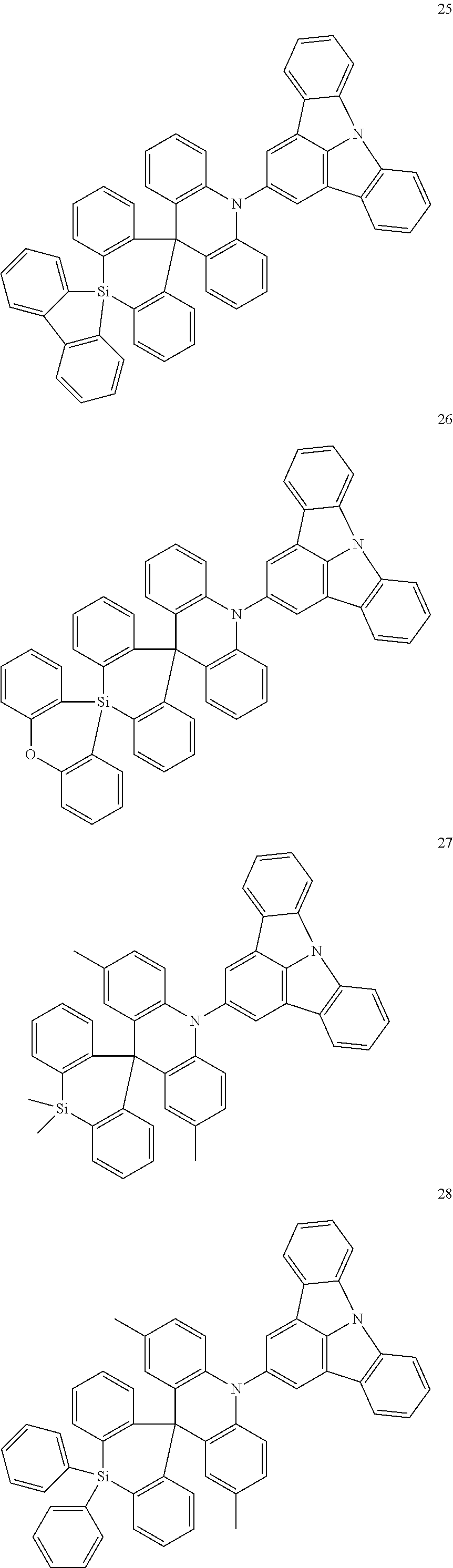


| TABLE 1 | |||
| S1 energy level | T1 energy level | |
|
| Example Compound 3 | 2.77 | 2.74 | 0.03 |
| Example Compound 6 | 2.80 | 2.77 | 0.03 |
| Example Compound 8 | 2.81 | 2.77 | 0.04 |
| Example Compound 14 | 2.67 | 2.64 | 0.03 |
| Example Compound 37 | 2.80 | 2.77 | 0.03 |
| Comparative Compound X-1 | 3.37 | 2.76 | 0.61 |
| Comparative Compound X-2 | 2.84 | 2.54 | 0.30 |
| Comparative Compound X-3 | 3.03 | 2.86 | 0.33 |
| Comparative Compound X-4 | 2.77 | 2.42 | 0.35 |
| TABLE 2 | ||||
| Emission layer material | λmax (nm) | ηext | ||
| Example Compound 3 | 448 | 11 | ||
| Example Compound 6 | 452 | 16 | ||
| Example Compound 8 | 450 | 17 | ||
| Example Compound 14 | 453 | 16 | ||
| Example Compound 37 | 450 | 12 | ||
| Comparative Compound X-1 | 473 | 4 | ||
| Comparative Compound X-2 | 460 | 1 | ||
| Comparative Compound X-3 | 475 | 2 | ||
| Comparative Compound X-4 | 470 | 1 | ||
Claims (20)
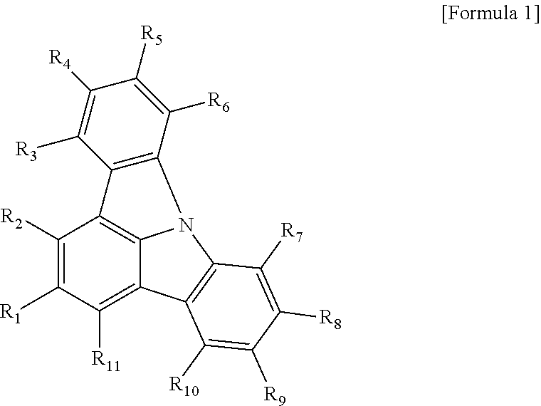


Applications Claiming Priority (2)
| Application Number | Priority Date | Filing Date | Title |
|---|---|---|---|
| KR1020170060153A KR102376873B1 (en) | 2017-05-15 | 2017-05-15 | Heterocyclic compound and organic electroluminescence device including the same |
| KR10-2017-0060153 | 2017-05-15 |
Publications (2)
| Publication Number | Publication Date |
|---|---|
| US20180331303A1 US20180331303A1 (en) | 2018-11-15 |
| US10862050B2 true US10862050B2 (en) | 2020-12-08 |
Family
ID=64095805
Family Applications (1)
| Application Number | Title | Priority Date | Filing Date |
|---|---|---|---|
| US15/941,061 Active 2039-01-02 US10862050B2 (en) | 2017-05-15 | 2018-03-30 | Heterocyclic compound and organic electroluminescence device including the same |
Country Status (2)
| Country | Link |
|---|---|
| US (1) | US10862050B2 (en) |
| KR (1) | KR102376873B1 (en) |
Families Citing this family (2)
| Publication number | Priority date | Publication date | Assignee | Title |
|---|---|---|---|---|
| CN111848620A (en) * | 2019-04-30 | 2020-10-30 | 江西冠能光电材料有限公司 | Organic light-emitting compound and application of organic light-emitting device thereof |
| CN110483564B (en) * | 2019-08-13 | 2022-02-01 | 武汉华星光电半导体显示技术有限公司 | Organic compound, application thereof and organic light-emitting diode electroluminescent device |
Citations (10)
| Publication number | Priority date | Publication date | Assignee | Title |
|---|---|---|---|---|
| WO2011088877A1 (en) | 2010-01-25 | 2011-07-28 | Merck Patent Gmbh | Compounds for electronic devices |
| KR20150002219A (en) | 2013-06-28 | 2015-01-07 | 주식회사 이엘엠 | Organic Light Emitting Material and Organic Light Emitting Diode Having The Same |
| US20150333273A1 (en) | 2014-05-15 | 2015-11-19 | Samsung Electronics Co., Ltd. | Condensed cyclic compound and organic light-emitting device including the same |
| KR20160026101A (en) * | 2014-08-29 | 2016-03-09 | 숭실대학교산학협력단 | System and method for updating secret key |
| KR20160045569A (en) | 2014-10-17 | 2016-04-27 | 엘지디스플레이 주식회사 | Delayed fluorescence compound, and Organic light emitting diode device and Display device using the same |
| KR20160045570A (en) | 2014-10-17 | 2016-04-27 | 엘지디스플레이 주식회사 | Delayed Fluorescence compound, and Organic light emitting diode device and Display device using the same |
| US20160260908A1 (en) | 2015-03-05 | 2016-09-08 | Univeral Display Corporation | Organic electroluminescent materials and devices |
| US20160293853A1 (en) | 2015-04-06 | 2016-10-06 | Universal Display Corporation | Organic Electroluminescent Materials and Devices |
| KR20160133545A (en) | 2014-03-18 | 2016-11-22 | 메르크 파텐트 게엠베하 | Organic electroluminescent device |
| US9711735B2 (en) | 2014-10-17 | 2017-07-18 | Lg Display Co., Ltd. | Delayed fluorescence compound, and organic light emitting diode and display device using the same |
Family Cites Families (2)
| Publication number | Priority date | Publication date | Assignee | Title |
|---|---|---|---|---|
| KR102454042B1 (en) * | 2014-10-17 | 2022-10-14 | 엘지디스플레이 주식회사 | Delayed Fluorescence compound, and Organic light emitting diode device and Display device using the same |
| KR101837825B1 (en) * | 2016-03-04 | 2018-04-26 | 성균관대학교산학협력단 | Delayed fluorescence material and organic light emitting device having the delayed fluorescence material |
-
2017
- 2017-05-15 KR KR1020170060153A patent/KR102376873B1/en active IP Right Grant
-
2018
- 2018-03-30 US US15/941,061 patent/US10862050B2/en active Active
Patent Citations (14)
| Publication number | Priority date | Publication date | Assignee | Title |
|---|---|---|---|---|
| KR20120129922A (en) | 2010-01-25 | 2012-11-28 | 메르크 파텐트 게엠베하 | Compounds for electronic devices |
| WO2011088877A1 (en) | 2010-01-25 | 2011-07-28 | Merck Patent Gmbh | Compounds for electronic devices |
| US9708262B2 (en) | 2010-01-25 | 2017-07-18 | Merck Patent Gmbh | Compounds for electronic devices |
| KR20150002219A (en) | 2013-06-28 | 2015-01-07 | 주식회사 이엘엠 | Organic Light Emitting Material and Organic Light Emitting Diode Having The Same |
| KR20160133545A (en) | 2014-03-18 | 2016-11-22 | 메르크 파텐트 게엠베하 | Organic electroluminescent device |
| US20170092875A1 (en) | 2014-03-18 | 2017-03-30 | Merck Patent Gmbh | Organic electroluminescent device |
| US20150333273A1 (en) | 2014-05-15 | 2015-11-19 | Samsung Electronics Co., Ltd. | Condensed cyclic compound and organic light-emitting device including the same |
| KR20150131564A (en) | 2014-05-15 | 2015-11-25 | 삼성전자주식회사 | Condensed cyclic compound and organic light emitting device including the same |
| KR20160026101A (en) * | 2014-08-29 | 2016-03-09 | 숭실대학교산학협력단 | System and method for updating secret key |
| KR20160045569A (en) | 2014-10-17 | 2016-04-27 | 엘지디스플레이 주식회사 | Delayed fluorescence compound, and Organic light emitting diode device and Display device using the same |
| KR20160045570A (en) | 2014-10-17 | 2016-04-27 | 엘지디스플레이 주식회사 | Delayed Fluorescence compound, and Organic light emitting diode device and Display device using the same |
| US9711735B2 (en) | 2014-10-17 | 2017-07-18 | Lg Display Co., Ltd. | Delayed fluorescence compound, and organic light emitting diode and display device using the same |
| US20160260908A1 (en) | 2015-03-05 | 2016-09-08 | Univeral Display Corporation | Organic electroluminescent materials and devices |
| US20160293853A1 (en) | 2015-04-06 | 2016-10-06 | Universal Display Corporation | Organic Electroluminescent Materials and Devices |
Also Published As
| Publication number | Publication date |
|---|---|
| KR102376873B1 (en) | 2022-03-22 |
| KR20180125675A (en) | 2018-11-26 |
| US20180331303A1 (en) | 2018-11-15 |
Similar Documents
| Publication | Publication Date | Title |
|---|---|---|
| US11793068B2 (en) | Amine compound and organic electroluminescence device including the same | |
| US20200185626A1 (en) | Organic electroluminescence device and polycyclic compound for organic electroluminescence device | |
| US10333085B2 (en) | Polycyclic compound and organic electroluminescence device including the same | |
| US20180205019A1 (en) | Organic electroluminescence device | |
| US11165029B2 (en) | Amine compound and organic electroluminescence device including the same | |
| US12133454B2 (en) | Organic electroluminescence device and polycyclic compound for organic electroluminescence device | |
| US11563187B2 (en) | Nitrogen-containing compound-containing compound and organic electroluminescence device including the same | |
| US10673000B2 (en) | Heterocyclic compound and organic electroluminescence device including the same | |
| US10580993B2 (en) | Amine compound and organic electroluminescence device including the same | |
| US11276836B2 (en) | Organic electroluminescence device and polycyclic compound for organic electroluminescence device | |
| US11018306B2 (en) | Compound for thermally activated delayed fluorescence and organic electroluminescence device including the same | |
| US11174427B2 (en) | Aromatic compound and organic electroluminescence device including the same | |
| US10777753B2 (en) | Heterocyclic compound and organic electroluminescence device including the same | |
| US20190123287A1 (en) | Polycyclic compound and organic electroluminescence device including the same | |
| US10862050B2 (en) | Heterocyclic compound and organic electroluminescence device including the same | |
| US11393985B2 (en) | Organic electroluminescence device and polycyclic compound for organic electroluminescence device | |
| US20200280004A1 (en) | Heterocyclic compound and organic electroluminescence device including the same | |
| US11021484B2 (en) | Compound including nitrogen and organic electroluminescence device including the same | |
| US10550134B2 (en) | Heterocyclic compound and organic electroluminescence device including the same | |
| US20190148647A1 (en) | Nitrogen-containing compound and organic electroluminescence device including the same | |
| US11165026B2 (en) | Heterocyclic compound and organic electroluminescence device including the same | |
| US11515486B2 (en) | Organic electroluminescence device and polycyclic compound for organic electroluminescence device | |
| US11254694B2 (en) | Polycyclic compound and organic electroluminescence device including the same | |
| US10714693B2 (en) | Polycyclic compound and organic electroluminescence device including the same | |
| US11271169B2 (en) | Nitrogen-containing compound and organic electroluminescence device including the same |
Legal Events
| Date | Code | Title | Description |
|---|---|---|---|
| AS | Assignment |
Owner name: SAMSUNG DISPLAY CO., LTD., KOREA, REPUBLIC OF Free format text: ASSIGNMENT OF ASSIGNORS INTEREST;ASSIGNOR:AKASHI, NOBUTAKA;REEL/FRAME:045393/0585 Effective date: 20180316 |
|
| FEPP | Fee payment procedure |
Free format text: ENTITY STATUS SET TO UNDISCOUNTED (ORIGINAL EVENT CODE: BIG.); ENTITY STATUS OF PATENT OWNER: LARGE ENTITY |
|
| STPP | Information on status: patent application and granting procedure in general |
Free format text: DOCKETED NEW CASE - READY FOR EXAMINATION |
|
| STPP | Information on status: patent application and granting procedure in general |
Free format text: NON FINAL ACTION MAILED |
|
| STPP | Information on status: patent application and granting procedure in general |
Free format text: RESPONSE TO NON-FINAL OFFICE ACTION ENTERED AND FORWARDED TO EXAMINER |
|
| STCF | Information on status: patent grant |
Free format text: PATENTED CASE |
|
| CC | Certificate of correction | ||
| MAFP | Maintenance fee payment |
Free format text: PAYMENT OF MAINTENANCE FEE, 4TH YEAR, LARGE ENTITY (ORIGINAL EVENT CODE: M1551); ENTITY STATUS OF PATENT OWNER: LARGE ENTITY Year of fee payment: 4 |