US10770510B2 - Dual threshold voltage devices having a first transistor and a second transistor - Google Patents
Dual threshold voltage devices having a first transistor and a second transistor Download PDFInfo
- Publication number
- US10770510B2 US10770510B2 US15/865,135 US201815865135A US10770510B2 US 10770510 B2 US10770510 B2 US 10770510B2 US 201815865135 A US201815865135 A US 201815865135A US 10770510 B2 US10770510 B2 US 10770510B2
- Authority
- US
- United States
- Prior art keywords
- layer
- implementations
- core
- transistor
- channel
- Prior art date
- Legal status (The legal status is an assumption and is not a legal conclusion. Google has not performed a legal analysis and makes no representation as to the accuracy of the status listed.)
- Active
Links
- 230000009977 dual effect Effects 0.000 title abstract description 33
- 238000003860 storage Methods 0.000 claims description 64
- 230000005291 magnetic effect Effects 0.000 claims description 30
- 239000000463 material Substances 0.000 claims description 23
- 239000002019 doping agent Substances 0.000 claims description 19
- 125000006850 spacer group Chemical group 0.000 claims description 19
- 239000004020 conductor Substances 0.000 claims description 9
- 230000000694 effects Effects 0.000 claims description 4
- 239000000203 mixture Substances 0.000 claims description 3
- 229910021332 silicide Inorganic materials 0.000 abstract description 36
- FVBUAEGBCNSCDD-UHFFFAOYSA-N silicide(4-) Chemical compound [Si-4] FVBUAEGBCNSCDD-UHFFFAOYSA-N 0.000 abstract description 36
- 238000004519 manufacturing process Methods 0.000 abstract description 8
- 238000000034 method Methods 0.000 description 158
- 238000000151 deposition Methods 0.000 description 66
- 230000005415 magnetization Effects 0.000 description 65
- 229910052751 metal Inorganic materials 0.000 description 56
- 239000002184 metal Substances 0.000 description 56
- 230000008569 process Effects 0.000 description 53
- 238000005530 etching Methods 0.000 description 36
- HQVNEWCFYHHQES-UHFFFAOYSA-N silicon nitride Chemical compound N12[Si]34N5[Si]62N3[Si]51N64 HQVNEWCFYHHQES-UHFFFAOYSA-N 0.000 description 33
- 229910052581 Si3N4 Inorganic materials 0.000 description 29
- XUIMIQQOPSSXEZ-UHFFFAOYSA-N Silicon Chemical compound [Si] XUIMIQQOPSSXEZ-UHFFFAOYSA-N 0.000 description 20
- 229910052710 silicon Inorganic materials 0.000 description 20
- 239000010703 silicon Substances 0.000 description 20
- 239000011248 coating agent Substances 0.000 description 18
- 238000000576 coating method Methods 0.000 description 18
- MZLGASXMSKOWSE-UHFFFAOYSA-N tantalum nitride Chemical compound [Ta]#N MZLGASXMSKOWSE-UHFFFAOYSA-N 0.000 description 18
- 238000004151 rapid thermal annealing Methods 0.000 description 17
- 238000001312 dry etching Methods 0.000 description 13
- 229920002120 photoresistant polymer Polymers 0.000 description 12
- 230000004888 barrier function Effects 0.000 description 11
- 239000006117 anti-reflective coating Substances 0.000 description 10
- 230000005294 ferromagnetic effect Effects 0.000 description 10
- 229910021420 polycrystalline silicon Inorganic materials 0.000 description 10
- 229920005591 polysilicon Polymers 0.000 description 10
- 239000011521 glass Substances 0.000 description 8
- 238000001039 wet etching Methods 0.000 description 8
- 150000002500 ions Chemical class 0.000 description 7
- 230000000873 masking effect Effects 0.000 description 7
- 239000000758 substrate Substances 0.000 description 7
- KWYUFKZDYYNOTN-UHFFFAOYSA-M Potassium hydroxide Chemical compound [OH-].[K+] KWYUFKZDYYNOTN-UHFFFAOYSA-M 0.000 description 6
- VYPSYNLAJGMNEJ-UHFFFAOYSA-N Silicium dioxide Chemical compound O=[Si]=O VYPSYNLAJGMNEJ-UHFFFAOYSA-N 0.000 description 6
- 238000005229 chemical vapour deposition Methods 0.000 description 6
- 238000010586 diagram Methods 0.000 description 6
- 230000000379 polymerizing effect Effects 0.000 description 6
- YCKRFDGAMUMZLT-UHFFFAOYSA-N Fluorine atom Chemical compound [F] YCKRFDGAMUMZLT-UHFFFAOYSA-N 0.000 description 5
- 229910052731 fluorine Inorganic materials 0.000 description 5
- 239000011737 fluorine Substances 0.000 description 5
- 239000007943 implant Substances 0.000 description 5
- 229910052814 silicon oxide Inorganic materials 0.000 description 5
- 239000000126 substance Substances 0.000 description 5
- QVGXLLKOCUKJST-UHFFFAOYSA-N atomic oxygen Chemical compound [O] QVGXLLKOCUKJST-UHFFFAOYSA-N 0.000 description 4
- 230000015572 biosynthetic process Effects 0.000 description 4
- 230000008859 change Effects 0.000 description 4
- 239000003989 dielectric material Substances 0.000 description 4
- 239000003302 ferromagnetic material Substances 0.000 description 4
- 239000010408 film Substances 0.000 description 4
- 230000006870 function Effects 0.000 description 4
- 150000002894 organic compounds Chemical class 0.000 description 4
- 239000001301 oxygen Substances 0.000 description 4
- 229910052760 oxygen Inorganic materials 0.000 description 4
- 238000005498 polishing Methods 0.000 description 4
- 230000004044 response Effects 0.000 description 4
- 238000004528 spin coating Methods 0.000 description 3
- 239000010936 titanium Substances 0.000 description 3
- MHAJPDPJQMAIIY-UHFFFAOYSA-N Hydrogen peroxide Chemical compound OO MHAJPDPJQMAIIY-UHFFFAOYSA-N 0.000 description 2
- 230000008878 coupling Effects 0.000 description 2
- 238000010168 coupling process Methods 0.000 description 2
- 238000005859 coupling reaction Methods 0.000 description 2
- 238000007598 dipping method Methods 0.000 description 2
- 238000011049 filling Methods 0.000 description 2
- 238000010884 ion-beam technique Methods 0.000 description 2
- 238000002955 isolation Methods 0.000 description 2
- 239000000395 magnesium oxide Substances 0.000 description 2
- CPLXHLVBOLITMK-UHFFFAOYSA-N magnesium oxide Inorganic materials [Mg]=O CPLXHLVBOLITMK-UHFFFAOYSA-N 0.000 description 2
- AXZKOIWUVFPNLO-UHFFFAOYSA-N magnesium;oxygen(2-) Chemical compound [O-2].[Mg+2] AXZKOIWUVFPNLO-UHFFFAOYSA-N 0.000 description 2
- 239000000696 magnetic material Substances 0.000 description 2
- 238000012986 modification Methods 0.000 description 2
- 230000004048 modification Effects 0.000 description 2
- 150000004767 nitrides Chemical class 0.000 description 2
- VHUUQVKOLVNVRT-UHFFFAOYSA-N Ammonium hydroxide Chemical compound [NH4+].[OH-] VHUUQVKOLVNVRT-UHFFFAOYSA-N 0.000 description 1
- ZOXJGFHDIHLPTG-UHFFFAOYSA-N Boron Chemical compound [B] ZOXJGFHDIHLPTG-UHFFFAOYSA-N 0.000 description 1
- 229910026161 MgAl2O4 Inorganic materials 0.000 description 1
- -1 Silicon dioxide compound Chemical class 0.000 description 1
- RTAQQCXQSZGOHL-UHFFFAOYSA-N Titanium Chemical compound [Ti] RTAQQCXQSZGOHL-UHFFFAOYSA-N 0.000 description 1
- 239000000908 ammonium hydroxide Substances 0.000 description 1
- 230000003667 anti-reflective effect Effects 0.000 description 1
- 238000003491 array Methods 0.000 description 1
- 229910052796 boron Inorganic materials 0.000 description 1
- 230000000295 complement effect Effects 0.000 description 1
- 150000001875 compounds Chemical class 0.000 description 1
- 238000013016 damping Methods 0.000 description 1
- 230000007423 decrease Effects 0.000 description 1
- 230000001419 dependent effect Effects 0.000 description 1
- 230000008021 deposition Effects 0.000 description 1
- 239000012777 electrically insulating material Substances 0.000 description 1
- 238000005516 engineering process Methods 0.000 description 1
- 230000002349 favourable effect Effects 0.000 description 1
- BHEPBYXIRTUNPN-UHFFFAOYSA-N hydridophosphorus(.) (triplet) Chemical compound [PH] BHEPBYXIRTUNPN-UHFFFAOYSA-N 0.000 description 1
- 229910000765 intermetallic Inorganic materials 0.000 description 1
- 238000001020 plasma etching Methods 0.000 description 1
- 230000010287 polarization Effects 0.000 description 1
- 239000004065 semiconductor Substances 0.000 description 1
- 239000000377 silicon dioxide Substances 0.000 description 1
- 235000012239 silicon dioxide Nutrition 0.000 description 1
- 229910052596 spinel Inorganic materials 0.000 description 1
- 230000002269 spontaneous effect Effects 0.000 description 1
- 239000010409 thin film Substances 0.000 description 1
- 229910052719 titanium Inorganic materials 0.000 description 1
- 230000005641 tunneling Effects 0.000 description 1
Images


Classifications
-
- H—ELECTRICITY
- H10—SEMICONDUCTOR DEVICES; ELECTRIC SOLID-STATE DEVICES NOT OTHERWISE PROVIDED FOR
- H10B—ELECTRONIC MEMORY DEVICES
- H10B61/00—Magnetic memory devices, e.g. magnetoresistive RAM [MRAM] devices
- H10B61/20—Magnetic memory devices, e.g. magnetoresistive RAM [MRAM] devices comprising components having three or more electrodes, e.g. transistors
- H10B61/22—Magnetic memory devices, e.g. magnetoresistive RAM [MRAM] devices comprising components having three or more electrodes, e.g. transistors of the field-effect transistor [FET] type
-
- H01L27/228—
-
- H01L29/7831—
-
- H01L29/0657—
-
- H01L29/7827—
-
- H01L43/02—
-
- H—ELECTRICITY
- H10—SEMICONDUCTOR DEVICES; ELECTRIC SOLID-STATE DEVICES NOT OTHERWISE PROVIDED FOR
- H10N—ELECTRIC SOLID-STATE DEVICES NOT OTHERWISE PROVIDED FOR
- H10N50/00—Galvanomagnetic devices
- H10N50/80—Constructional details
Definitions
- This relates generally to the field of memory applications and voltage devices, including but not limited to dual threshold voltage devices.
- a device comprising a core, a plurality of layers that surround the core in succession, including a first layer, a second layer, a third layer, and a fourth layer.
- the core, the first layer, and the second layer correspond to a first transistor.
- the core is the gate of the first transistor
- the first layer is the gate dielectric of the first transistor
- the second layer serves as a channel of the first transistor as well as a channel of the second transistor.
- the second layer, the third layer, and the fourth layer correspond to a second transistor.
- the third layer is a gate dielectric for the second transistor and the fourth layer is a gate of the second transistor.
- the second layer is a common channel for the first and second transistors.
- the device further comprises a first input terminal coupled to the core, the first input terminal being configured to receive a first voltage and a second input terminal coupled to the fourth layer, the second input terminal being configured to receive a second voltage.
- the device further comprises a common source terminal coupled to the core and the fourth layer.
- the device further comprises a common source terminal for both transistors which is a lower portion of the common cylindrical channel.
- the upper portion of the cylindrical channel serves as a common drain for the first and second transistors.
- a memory device such as an MTJ is coupled to the channel drain of the device (e.g., the dual Vt transistors).
- a device for easily programming an MTJ the device having two threshold voltages, is provided.
- An exemplary device is provided in FIG. 5 .
- some implementations include a method of fabricating an annular device (e.g., an annular dual threshold voltage device).
- the method comprises providing a cylindrical device having a conductive core corresponding to a first transistor and a plurality of annular layers surrounding the core, including a first dielectric layer, a second layer, a third dielectric layer, and a fourth conductive layer corresponding to a second transistor and creating a silicide source, wherein the silicide source is coupled to the conductive core corresponding to the first transistor and the fourth conductive layer corresponding to the second transistor.
- the method of creating the silicide source includes coating a first oxide substrate with an organic polymerizing layer (OPL) to create an OPL plane, wherein the OPL plane surrounds a horizontal cross section of the cylindrical device and depositing low-temperature silicon oxide (LTO) on the OPL to create an LTO layer, wherein the LTO layer surrounds a horizontal cross section of the cylindrical device.
- the method of creating the silicide source further includes coating the LTO layer with a bottom antireflective coating (BARC) layer and a photoresistive (PR) layer, applying a layer of silicide to create the silicide source and creating a mask with the PR layer, wherein the mask covers the second layer of the cylindrical device.
- BARC bottom antireflective coating
- PR photoresistive
- the method further includes dry etching the BARC layer, the LTO layer and the OPL until the oxide substrate is exposed and then etching horizontally the LTO layer and oxide to expose a layer of silicon on a horizontal cross section of the cylindrical device to create an annular area.
- the method further includes Ion Implanting a source dopant and performing a first rapid thermal annealing (RTA) on the annular area to reduce its electrical resistance and then depositing a siliciding metal on the annular area to create the silicide source and performing a second RTA to reduce its electrical resistance.
- RTA rapid thermal annealing
- some implementations include a method for fabricating an annular device, including an annular polycide layer.
- the method comprises forming a cylindrical device having a conductive core corresponding to a first transistor and a plurality of annular layers surrounding the core, including a first dielectric layer, a second layer, a third dielectric layer, and a fourth conductive layer corresponding to a second transistor.
- the method further comprises coating a spin-on glass (SOG) layer on a first plane and the cylindrical device to create a sloped ring around the bottom of the cylindrical device, wherein the cylindrical device is vertically disposed in the first plane and the SOG surrounds the cylindrical device.
- SOG spin-on glass
- the method further comprises etching the SOG layer from around and inside the cylindrical device to a desired depth and depositing dielectric materials to form the third dielectric layer.
- the method further includes depositing doped chemically vaporized polysilicon on the first plane, a horizontal cross section of the cylindrical device, a top of the cylindrical device, and the sloped ring around the cylindrical device (e.g., using chemically vaporized deposition).
- the method further includes etching, using a reactive-ion etch (RIE), the polysilicon on the top of the cylindrical device and on the sloped ring and depositing a siliciding metal and performing rapid thermal anneal (RTA) to create the fourth conductive layer of reduced electrical resistivity.
- RIE reactive-ion etch
- some implementations include a method for fabricating an annular device, including creating a contact between a required node of the device to other metal connections.
- Some aspects of the method include providing a cylindrical device having a conductive core corresponding to a first transistor and a plurality of annular layers surrounding the core, including a first dielectric layer, a second layer, a third dielectric layer, and a fourth conductive layer corresponding to a second transistor, wherein the fourth conductive layer is an outermost layer of the cylindrical device.
- Some methods include converting the fourth conductive layer of the CVD polysilicon to a low resistivity silicide a gate of the second transistor.
- This may include depositing a first low-temperature oxide (LTO) layer to create a first LTO plane and spin coating a spin-on glass (SOG) layer in the first LTO plane, wherein the cylindrical device is vertically disposed in the first LTO plane.
- the method for making a contact to the conductive layer for the gate of the second transistor includes etching the SOG layer to a first thickness and spin coating an organic compound to a first height to create an organic planarizing layer (OPL), wherein the OPL surrounds a horizontal cross section of the cylindrical device.
- OPL organic planarizing layer
- the method further includes depositing a second LTO layer onto the OPL, wherein the second LTO layer surrounds a horizontal cross section of the cylindrical device, and coating the second LTO layer with a bottom anti-reflective coating (BARC) layer.
- the method further includes coating the BARC layer with a photoresist layer, wherein the BARC layer and the photoresist layer surround a horizontal cross section of the cylindrical device and creating a mask with the photoresist layer.
- the method further includes dry etching the BARC layer and the second LTO layer using a fluorine-based chemistry through the BARC layer and the second LTO layer into the OPL, wherein the dry etching areas is defined by the mask layout of the photoresist pattern layer.
- the method further includes etching the OPL in oxygen plasma until the SOG layer is exposed to create a trench and depositing tantalum nitride in the trench to create a contact from the silicided polysilicon of the gate to the metal lines needed for the memory device or connection to the logic devices.
- some implementations include a method for fabricating an annular device, including creating a contact between a core of a device and any other metal line for connection to a given core.
- the method comprises providing a cylindrical device having a conductive core corresponding to a first transistor and a plurality of annular layers surrounding the core, including a first dielectric layer, a second layer, a third dielectric layer, and a fourth conductive layer corresponding to a second transistor.
- the method further comprises coupling (or providing access to couple) the conductive core of the cylindrical device to other metal nodes. This includes depositing, by chemical vapor deposition (CVD), a first silicon nitride (SiN) layer to create a first SiN plane.
- CVD chemical vapor deposition
- SiN silicon nitride
- the method further includes depositing a spin-on glass (SOG) layer and a low temperature oxide (LTO) layer and performing a metal gate contact mask.
- the method further includes etching, using an ion beam trench etch, to create a trench through the plurality of annular layers surrounding the core and depositing a second SiN layer in the trench and on sides of the trench.
- the method further includes removing the deposited first SiN layer from the core by a first chemical mechanical polishing (CMP) and depositing a metal gate contact and metal lines to create a contact from the conductive core to outer metal lines.
- CMP chemical mechanical polishing
- devices and systems are provided with methods for fabricating and operating dual threshold (e.g., dual gate) devices, thereby increasing the effectiveness, efficiency, and user satisfaction with such systems and devices.
- dual threshold e.g., dual gate
- FIG. 1A shows a schematic diagram of a representative magnetic tunnel junction (MTJ) structure in accordance with some implementations.
- MTJ magnetic tunnel junction
- FIG. 1B shows representative energy barriers of the reference and storage layers of the MTJ of FIG. 1A in accordance with some implementations.
- FIGS. 2A-2B illustrate magnetization orientations in a representative perpendicular magnetic tunnel junction (pMTJ) structure in accordance with some implementations.
- pMTJ perpendicular magnetic tunnel junction
- FIGS. 3A-3D illustrate representative processes for switching the pMTJ of FIGS. 2A-2B between the parallel and anti-parallel configurations in accordance with some implementations.
- FIG. 4 is a schematic diagram of a representative spin transfer torque (STT) MRAM device in accordance with some implementations.
- FIG. 5 illustrates a dual threshold voltage device in accordance with some implementations.
- FIG. 6 illustrates a dual threshold voltage device with aligned gate handles in accordance with some implementations.
- FIG. 7 is a schematic diagram of a representative circuit in accordance with some implementations.
- FIG. 8 is a schematic of a dual threshold voltage device and MTJ structure in accordance with some implementations.
- FIGS. 9A-9C, 10A-10B, 11A-11C, 12A-12C, 13A-13B, 14, and 15A-15C illustrate a process for forming a silicide source in accordance with some implementations.
- FIGS. 9A-9C illustrate a process of forming a channel in accordance with some implementations.
- FIGS. 10A-10B illustrate a doping process in accordance with some implementations.
- FIGS. 11A-11C illustrate a process of forming annular layers in accordance with some implementations.
- FIGS. 12A-12C illustrate an etching process in accordance with some implementations.
- FIGS. 13A-13B illustrate an annular device in accordance with some implementations.
- FIG. 14 illustrates a schematic view of both an N-device and a P-device in accordance with some implementations.
- FIGS. 15A-15C illustrate a siliciding process in accordance with some implementations.
- FIGS. 16A-16C, 17A-17B, and 18 illustrate processes for forming an annular transistor in accordance with some implementations.
- FIGS. 16A-16C illustrate a process of forming a gate structure on an annular device in accordance with some implementations.
- FIGS. 17A-17B illustrate a process of depositing polysilicon on an annular device in accordance with some implementations.
- FIG. 18 illustrates a post-etching state of the annular device in accordance with some implementations.
- FIGS. 19A-19B illustrate a process for creating a gate handle for a transistor in accordance with some implementations.
- FIGS. 20A-20D illustrate a device having a source and an annular transistor in accordance with some implementations.
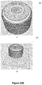
- FIGS. 20E-20G illustrate a representative process of planarizing a representative device in accordance with some implementations.
- FIGS. 20H-20K illustrate a representative process for adjusting heights of a representative device in accordance with some implementations.
- FIGS. 21A-21G, 22A-22C and 23A-23C illustrate a representative process for creating a contact for a transistor located in the center of an annular device in accordance with some implementations.
- FIGS. 21A-21G illustrate a planarization process for an annular device in accordance with some implementations.
- FIGS. 22A-22C illustrate a process for etching an annular device in accordance with some implementations.
- FIGS. 23A-23C illustrate a process for contacting a layer of an annular device in accordance with some implementations.
- FIG. 24 illustrates an array of dual threshold voltage devices in accordance with some implementations.
- a device, and a method of fabricating the device, having dual threshold voltages has a core, a plurality of layers that surround the core in succession, including a first layer, a second layer, a third layer, and a fourth layer.
- the core, the first layer, and the second layer correspond to a first transistor.
- the second layer, the third layer, and the fourth layer correspond to a second transistor.
- the second layer is a common channel for the first and second transistors.
- the device further comprises a first input terminal coupled to the core, the first input terminal being configured to receive a first voltage and a second input terminal coupled to the fourth layer, the second input terminal being configured to receive a second voltage.
- the device further comprises a common source terminal coupled to the core and the fourth layer (but not physically or electrically shorting).
- a memory device such as an MTJ is coupled to the drain side of the channel of the device.
- dual threshold voltage, dual transistor CMOS devices are provided.
- cylindrical pillars are etched out of silicon for CMOS devices (e.g., ⁇ 100> silicon).
- the channels are annular vertical cylinders etched into silicon.
- the source comprises bottom silicided areas of the annular cylinder of silicon and the drain is the top part of the channel.
- the innermost cylinder makes the first transistor (e.g., Gate 1 ) electrode with a first threshold voltage (e.g., Vt 1 ).
- the outer wrap around the poly cylinder makes the second transistor (e.g., Gate 2 ) with a second threshold voltage (e.g., Vt 2 ).
- the first threshold voltage and the second threshold voltage of the N and/or P type devices can be individually tailored by proper choices of: the dopant of the cylindrical pillar, the thickness of the gates' dielectrics, the dielectric constant of their gates' materials, and the/or the work functions of the gate electrodes.
- the thicker the cylindrical pillar means the greater the drive currents will be.
- the combined drive current is an order of magnitude more than a surface device with a given photolithographic step (F, minimum feature size).
- F photolithographic step
- the shallower the pillar the faster will be the speed of the vertical channel transistors.
- having a dual threshold voltage device saves real estate (e.g., space) in the layout in analog CMOS circuits, digital, and/or memory.
- Magnetoresistive random access memory is a non-volatile memory technology that stores data through magnetic storage elements.
- MRAM devices store information by changing the orientation of the magnetization of a storage layer. For example, based on whether the storage layer is in a parallel or anti-parallel alignment relative to a reference layer, either a “1” or a “0” can be stored in each MRAM cell.
- MRAM stores data through magnetic storage elements. These elements typically include two ferromagnetic films or layers that can hold a magnetic field and are separated by a non-magnetic material. In general, one of the layers has its magnetization pinned (e.g., a “reference layer”), meaning that this layer requires a large magnetic field or spin-polarized current to change the orientation of its magnetization.
- the second layer is typically referred to as the storage, or free, layer and its magnetization direction can be changed by a smaller magnetic field or spin-polarized current relative to the reference layer.
- MRAM devices Due to the spin-polarized electron tunneling effect, the electrical resistance of the cell changes due to the orientation of the magnetization of the two layers. A memory cell's resistance will be different for the parallel and anti-parallel states and thus the cell's resistance can be used to distinguish between a “1” and a “0”.
- MRAM devices are non-volatile memory devices, since they maintain the information even when the power is off.
- the layers can be sub-micron in lateral size and the magnetization direction can still be stable over time and with respect to thermal fluctuations.
- FIG. 1A is schematic diagram of a magnetic tunnel junction (MTJ) structure 100 (e.g., for use in an MRAM device) in accordance with some implementations.
- the MTJ structure 100 is composed of a first ferromagnetic layer (reference layer 102 ), a second ferromagnetic layer (storage layer 106 ), and a non-magnetic layer (spacer layer 104 ).
- the reference layer 102 is also sometimes referred to as a pinned or fixed layer.
- the storage layer 106 is also sometimes referred to as a free layer.
- the spacer layer 104 is also sometimes referred to as a barrier layer (or a non-magnetic spacer layer).
- the spacer layer 104 comprises an electrically-insulating material such as magnesium oxide (MgO) or MgAl 2 O 4 .
- MgO magnesium oxide
- MgAl 2 O 4 MgAl 2 O 4
- the reference layer 102 and the storage layer 106 are composed of the same ferromagnetic material. In some implementations, the reference layer 102 and the storage layer 106 are composed of different ferromagnetic materials. In some implementations, the reference layer 102 is composed of a ferromagnetic material that has a higher coercivity and/or thermal stability than the storage layer 106 . In some implementations, the reference layer 102 and the storage layer 106 are composed of different ferromagnetic materials with the same or similar thicknesses (e.g., within 10%, 5%, or 1% of one another).
- the thickness of the reference layer 102 is different from that of the storage layer 106 (e.g., the reference layer 102 is thicker than the storage layer 106 ).
- the thickness of the spacer layer 104 is on the order of a few atomic layers. In some implementations, the thickness of the spacer layer 104 is on the order of a few nanometers (nm). In some implementations, thicknesses of the reference layer 102 , the spacer layer 104 , and the storage layer 106 are uniform.
- thicknesses of the reference layer 102 , the spacer layer 104 , and the storage layer 106 are not uniform (e.g., a first portion of the spacer layer 104 is thinner relative to a second portion of the spacer layer 104 ).
- the reference layer 102 and/or the storage layer 106 is composed of two or more ferromagnetic layers are separated from one another with spacer layers.
- each of these ferromagnetic layers is composed of identical, or varying, thickness(es) and/or material(s).
- the spacer layers are composed of identical, or varying, thickness(es) and/or material(s) with respect to one another.
- Magnetic anisotropy refers to the directional dependence of a material's magnetic properties.
- the magnetic moment of magnetically anisotropic materials will tend to align with an “easy axis,” which is the energetically favorable direction of spontaneous magnetization.
- the two opposite directions along an easy axis are equivalent, and the direction of magnetization can be along either of them (and in some cases, about them).
- FIG. 1B shows low energy states 114 and 116 corresponding to opposite directions along an easy axis (additional examples are shown in FIGS. 10A-10B with reference to a cylindrical three-dimensional MTJ structure).
- the MTJ structure 100 is an in-plane MTJ.
- the magnetic moments of the reference layer 102 and the storage layer 106 are oriented in the plane of the ferromagnetic films of the reference layer 102 and the storage layer 106 .
- the MTJ structure 100 is a perpendicular (or out-of-plane) MTJ.
- the magnetic moments of the reference layer 102 and the storage layer 106 are oriented perpendicular and out-of-plane to the ferromagnetic films of the reference layer 102 and the storage layer 106 .
- the MTJ structure 100 has preferred directions of magnetization at arbitrary angles with respect to the magnetic films of the reference layer 102 and the storage layer 106 .
- an MRAM device provides at least two states such that they can be assigned to digital signals “0” and “1,” respectively.
- One storage principle of an MRAM is based on the energy barrier required to switch the magnetization of a single-domain magnet (e.g., switch the magnetization of the storage layer 106 ) from one direction to the other.
- FIG. 1B shows representative energy barriers of the reference layer 102 and the storage layer 106 of the MTJ 100 in accordance with some implementations.
- the energy barrier refers the amount of energy the magnetic material must overcome in order to switch from one magnetization direction to its opposite (e.g., from the state 114 to the state 116 ).
- the magnetization direction of the reference layer 102 is generally considered fixed, while the magnetization direction of the storage layer 106 is varied to store the “0” and “1” states.
- the reference layer 102 is composed of materials such that an energy barrier 112 (E B, ref ) of the reference layer 102 is larger than the energy barrier 118 (E B, stor ) of the storage layer 106 .
- FIG. 1B shows low energy states 114 and 116 for the reference layer 102 separated by the energy barrier 112 , and shows low energy states 120 and 122 for the storage layer 106 separated by the energy barrier 118 .
- the storage layer 106 is designed with materials that have a magnetic anisotropy that is high enough to store the magnetization over certain time duration (for e.g., 1 week, 1 month, 1 year, or 10 years).
- the resistance states of the MRAM devices are different when the magnetization directions of the reference layer 102 and the storage layer 106 are aligned in a parallel (low resistance state) configuration or in an anti-parallel (high resistance state) configuration, as will be discussed with respect to FIGS. 2A and 2B .
- FIGS. 2A-2B illustrate magnetization orientations in a perpendicular magnetic tunnel junction (pMTJ) structure 200 in accordance with some implementations.
- the pMTJ structure 200 is the same as the MTJ structure 100 presented in FIG. 1A , comprising: the reference layer 102 , the spacer layer 104 , and the storage layer 106 .
- the pMTJ structure 200 forms part of a MRAM device.
- the fixed magnetization direction 202 for the reference layer 102 is chosen to be in an upward direction and is represented by an up arrow. In some implementations (not shown), the fixed magnetization direction of the reference layer 102 in the pMTJ structure 200 is in a downward direction.
- FIG. 2A illustrates the magnetization directions of the storage and reference layers in a parallel configuration.
- the magnetization direction 206 of the storage layer 106 is the same as the magnetization direction 202 of the reference layer 102 .
- the magnetization direction 202 of the reference layer 102 and the magnetization direction 206 of the storage layer 106 are both in the upward direction.
- the magnetization direction of the storage layer 106 relative to the fixed layer 102 changes the electrical resistance of the pMTJ structure 200 .
- the electrical resistance of the pMTJ structure 200 is low when the magnetization direction of the storage layer 106 is the same as the magnetization direction 202 of the reference layer 102 .
- the parallel configuration is also sometimes referred to as a “low (electrical) resistance” state.
- FIG. 2B illustrates the magnetization directions of the storage and reference layers in an anti-parallel configuration.
- the magnetization direction 216 of the storage layer 106 is opposite to the “fixed” magnetization direction 202 of the reference layer 102 .
- the electrical resistance of the pMTJ structure 200 is high when the magnetization direction 216 of the storage layer 106 is the opposite of the magnetization direction 202 of the reference layer 102 . Accordingly, the anti-parallel configuration is sometimes also referred to as a “high (electrical) resistance” state.
- the resistance states of the pMTJ structure 200 can be varied between low resistance to high resistance, enabling digital signals corresponding to bits of “0” and “1” to be stored and read.
- the parallel configuration corresponds to a bit “0”
- the anti-parallel configuration corresponds to a bit “1”.
- FIGS. 2A-2B show parallel and anti-parallel configurations with the pMTJ structure 200 , in some implementations, an in-plane MTJ structure, or an MTJ structure with an arbitrary preferred angle, is used instead.
- FIGS. 3A-3D illustrate representative processes for switching the pMTJ 200 between the parallel and anti-parallel configurations in accordance with some implementations.
- spin-transfer torque is used to modify the magnetization directions of an MTJ.
- STT is an effect in which the magnetization direction of a ferromagnetic layer in an MTJ is modified by injecting a spin-polarized current into the magnetic element.
- electrons possess a spin, a quantized number of angular momentum intrinsic to the electron.
- An electrical current is generally unpolarized, e.g., it consists of 50% spin up and 50% spin down electrons.
- a current is applied though a ferromagnetic layer, the electrons are polarized with spin orientation corresponding to the magnetization direction of the ferromagnetic layer, thus producing a spin-polarized current (or spin-polarized electrons).
- the magnetization direction of the reference layer 102 is “fixed” in an MTJ (e.g., the applied currents are insufficient to change the magnetization state of the reference layer). Therefore, spin-polarized electrons may be used to switch the magnetization direction of the storage layer 106 in the MTJ (e.g., switch between parallel and anti-parallel configurations).
- the electrons when spin-polarized electrons travel to the magnetic region of the storage layer 106 in the MTJ, the electrons will transfer a portion of their spin-angular momentum to the storage layer 106 , to produce a torque on the magnetization of the storage layer 106 .
- the magnetization of the storage layer 106 switches, which, in effect, writes either a “1” or a “0” based on whether the storage layer 106 is in the parallel or anti-parallel configuration relative to the reference layer.
- FIGS. 3A-3B illustrate the process of switching from the anti-parallel configuration to the parallel configuration.
- the pMTJ structure 200 is in the anti-parallel configuration, e.g., the magnetization direction 302 of the reference layer 102 is opposite to the magnetization direction 306 of the storage layer 106 .
- FIG. 3B shows application of a current such that electrons flow through the pMTJ 200 in accordance with electron flow 312 .
- the electrons are directed through the reference layer 102 which has been magnetized with the magnetization direction 302 .
- As the electrons flow through the reference layer 102 they are polarized (at least in part) by the reference layer 102 and have spin orientation corresponding to the magnetization direction 302 of the reference layer 102 .
- the majority of the spin-polarized electrons tunnel through the spacer layer 104 without losing their polarization and subsequently exert torque on the orientation of magnetization of the storage layer 106 .
- the spin torque flips, or switches, the magnetization direction of the storage layer 106 from the magnetization direction 306 in FIG. 3A to the magnetization direction 316 in FIG. 3B .
- the magnetization direction 316 of the storage layer 106 is in the same (upward) direction as the magnetization direction 302 of the reference layer 102 . Accordingly, the pMTJ structure 200 in FIG. 3B is in the parallel (low resistance state) configuration. In some implementations and instances, electrons that possess spins in the minority (opposite) direction are reflected at the barrier interfaces and exert torque on the magnetization direction 302 of the reference layer 102 . However, the magnetization direction 302 of the reference layer 102 is not switched because the torque, e.g., the amount of electrons, is not sufficient to overcome the damping and hence insufficient to cause switching in the reference layer 102 .
- FIGS. 3C-3D illustrate the process of switching from the parallel configuration to the anti-parallel configuration.
- the pMTJ structure 200 is in the parallel configuration.
- a current is applied such that electrons flow in accordance with electron flow 322 in FIG. 3D .
- the electrons flow from the storage layer 106 to the reference layer 102 .
- the electrons flow through the storage layer 106 , they are polarized by the storage layer 106 and have spin orientation corresponding to the magnetization direction 316 of the storage layer 106 .
- the MTJ structure 200 in FIG. 3C is in the parallel (low resistance state) configuration and thus it has lower electrical resistance, therefore, in some implementations and instances, the majority of the spin-polarized electrons tunnel through the spacer layer 104 . Minority spin electrons that are polarized with direction opposite to the magnetization direction 316 of the storage layer 106 are reflected at the barrier interfaces of the spacer layer 104 . The reflected spin electrons then exert torque on the magnetization 316 of the storage layer 106 , eventually leading to a switch of the magnetization direction 316 of the storage layer 106 in FIG. 3C to a magnetization direction 326 in FIG. 3D . Thus, the pMTJ structure 200 is switched from the parallel (low resistance state) configuration to the anti-parallel (high resistance state) configuration.
- STT allows switching of the magnetization direction of the storage layer 106 .
- MRAM devices employing STT e.g., STT-MRAM
- STT-MRAM offer advantages including lower power consumption, faster switching, and better scalability, over conventional MRAM devices that use magnetic field to switch the magnetization directions.
- STT-MRAM also offers advantages over flash memory in that it provides memory cells with longer life spans (e.g., can be read and written to more times compared to flash memory).
- FIG. 4 is a schematic diagram of a spin transfer torque (STT) MRAM device 400 in accordance with some implementations.
- The includes an MTJ device with the reference layer 102 , the spacer layer 104 , the storage layer 106 , and an access transistor 414 .
- the MTJ device is coupled to a bit line 408 and a source line 410 via transistor 414 , which is operated by a word line 412 .
- the reference layer 102 , the spacer layer 104 , and the storage layer 106 compose the MTJ structure 100 and/or the pMTJ structure 200 , as described above with reference to FIGS. 1-3 .
- the STT-MRAM 400 includes additional read/write circuitry, one or more additional transistors, one or more sense amplifiers, and/or other components (not shown).
- the MTJ structure 100 and/or the pMTJ structure 200 is also sometimes referred to as an MRAM cell.
- the STT-MRAM 400 contains multiple MRAM cells (e.g., hundreds or thousands of MRAM cells) arranged in an array coupled to respective bit lines and source lines.
- a voltage is applied between the bit line 408 and the source line 410 (e.g., corresponding to a “0” or “1” value), and the word line 412 enables current to flow between the bit line 408 to the source line 410 .
- the current is sufficient to change a magnetization of the storage layer 106 and thus, depending on the direction of electron flow, bits of “0” and “1” are written into the MRAM cell (e.g., as illustrated in FIGS. 3A-3D ).
- the current is insufficient to change the magnetization of the storage layer 106 . Instead, a resistance across the MRAM cell is determined. e.g., with a low resistance corresponding to a logical “0” and a high resistance corresponding to a logical “1.”
- dual threshold voltage devices are able to store multiple bits in a compact layout.
- memory arrays can be produced using the dual threshold voltage devices as memory cells.
- dual threshold voltage devices can be implemented as current and/or voltage selectors for other circuit components, such as magnetic memory devices.
- Some magnetic memory devices require inputs with multiple voltage levels in order to effectively read from and write to the devices.
- the dual threshold voltage devices are optionally used (e.g., in place of larger, more complex analog circuitry) to modulate a voltage or current source so as to provide the required voltage and/or current levels.
- the input voltage requirements of some magnetic memory devices vary with the temperature of the magnetic memory devices. To achieve a desirable bit error rate (BER) across multiple temperatures, without excessive power consumption, a dual-threshold voltage is used in some implementations to regulate the input voltage/current for the magnetic memory device based on temperature.
- BER bit error rate
- FIG. 5 illustrates a device ( 500 ) in accordance with some implementations.
- the device comprises a core 502 and a plurality of layers that surround the core in succession, including a first (e.g., innermost) layer 504 , a second layer 506 , a third layer 508 and a fourth (e.g., outermost) layer 510 .
- the core 502 , the first layer 504 and the second layer 506 constitutes part of a first transistor.
- the second layer 506 , the third layer 508 and the fourth layer 510 correspond to a second transistor.
- the second layer 506 is a common channel for the first transistor and the second transistor.
- the device further includes a first input terminal 512 (e.g., connected to Gate 1 ) that is coupled to the core 502 and the first input terminal 512 is configured to receive a first voltage (e.g., is configured to have a first threshold voltage).
- the first threshold voltage is based on dopant type of the channel, dopant level of the channel, dielectric constant of first dielectric layer, thickness of first dielectric layer, and/or work function of the core.
- the device further includes a second input terminal 514 (e.g., connected to Gate 2 ) that is coupled to the fourth layer 510 and the second input terminal 514 is configured to receive a second voltage (e.g., is configured to have a second threshold voltage).
- the second threshold voltage is based on channel dopant type, channel dopant level, thickness of the third dielectric layer, and/or work function of the fourth conductive layer.
- the device further comprises a common source terminal 518 that is coupled to a source terminal of the channel (e.g., channel 804 ).
- the first input terminal 512 and the second input terminal 514 are outwardly disposed from the center of the device. In some implementations, there is an angle between the disposition of the first input terminal 512 and the second input terminal 514 (e.g., the first terminal and second terminal are spaced such that they do not share a vertical plane).
- the core is vertical and cylindrical in shape.
- the plurality of layers annularly surrounds the vertical cylindrical core and the core surrounded by the plurality of layers creates a cylindrical pillar (e.g., device 500 is shaped as a cylindrical pillar).
- the cylindrical pillar comprises core 502 , first layer 504 , second layer 506 , third layer 508 , and fourth layer 510 .
- the cylindrical pillar includes the first input terminal 512 , the second input terminal 514 and the drain terminal 506 .
- the core is composed of electrically lower resistive material such as tantalum nitride (TaN).
- the common source terminal 518 is composed of silicided areas coupled to a lower portion of the channel (e.g., the channel is also coupled to the drain of the device).
- the cylindrical source contact 520 is used and installed to provide electrical connection to the source 518 .
- Cylindrical source contact 520 provides methods to connect source of the dual voltage device to the outside power supply line.
- the core 502 is composed of a conductive material
- the first layer 504 is a first dielectric layer that surrounds the core 502
- the second layer 506 surrounds the first dielectric layer 504
- the third layer 508 is a third dielectric layer that surrounds the second layer 506
- the fourth layer 510 is composed of a conductive material and surrounds the third dielectric layer 508 .
- the fourth layer may be the outermost layer.
- the fourth layer 510 is composed of a polycide.
- FIG. 6 illustrates two implementations of a device ( 600 ) in accordance with some implementations.
- device 600 has components corresponding to the components of device 500 , described above, with the first input terminal and the second input terminal aligned to share a vertical plane (e.g., vertically stacked).
- a vertical plane e.g., vertically stacked
- the device 600 comprises a core 602 and a plurality of layers that surround the core in succession, including a first (e.g., innermost) layer 604 , a second layer 606 , a third layer 608 and a fourth (e.g., outermost) layer 610 .
- the core 602 , the first layer 604 and the second layer 606 correspond to a first transistor.
- the handle 616 also sometimes called contact 616 ) connected to the 606 drain is not provided and/or is not used (e.g., is not coupled to another device or component). For example, the handle 616 is not used in some MRAM memory applications.
- the second layer 606 , the third layer 608 and the fourth layer 610 correspond to a second transistor.
- the second layer 606 is a common channel (e.g., coupled to drain terminal 616 ) for the first transistor and the second transistor.
- the device further includes a terminal 612 , also sometimes called a contact 612 , (e.g., Gate 1 in example (ii)) that is coupled to the core 602 and the terminal 612 is configured to receive a first voltage (e.g., is configured to have a first threshold voltage).
- the device further includes a terminal 614 (e.g., Gate 2 in example (ii)) that is coupled to the fourth layer 610 and the terminal 614 is configured to receive a second voltage.
- the first input terminal 612 and the second input terminal 614 are stacked on top of each other (e.g., vertically aligned). In accordance with some implementations, stacking the terminals 612 and 614 enable production of an array of devices with a smaller pitch, as shown in FIG. 24 .
- an annular device (e.g., device 600 ) is provided.
- the annular device comprises a first transistor including a first input terminal (e.g., gate 1 handle) and a second transistor including a second input terminal (e.g., gate 2 handle).
- the first input terminal and the second input terminal extend radially outward from the annular device 600 and the first input terminal is aligned with the second input terminal.
- a magnetic tunnel junction coupled to the channel drain (e.g., at the top/above the cylindrical core), as described in greater detail with reference to FIG. 8 .
- the core is vertical and cylindrical in shape, the plurality of layers annularly surrounds the vertical cylindrical core, and the core surrounded by the plurality of layers creates a cylindrical pillar.
- the first transistor is configured to have a first threshold voltage having a first magnitude and the second transistor is configured to have a second threshold voltage having a second magnitude.
- the second magnitude is distinct from the first magnitude.
- the first threshold voltage and the second threshold voltage are based on a respective thickness for each of the dielectric layer thicknesses and the dopants of the channel and work function of the core and the plurality of layers.
- the first threshold voltage and the second threshold voltage are selected by changing one or more properties of the device selected from the group consisting of: a dopant of the device, a thickness of one or more of the plurality of layers, and material compositions of the first transistor and the second transistor.
- the common source terminal is composed of silicided areas coupled to a bottom plane of the core and the fourth layer.
- the core is composed of a conductive material
- the first layer is a first dielectric layer that surrounds the core
- the second layer surrounds the first dielectric layer
- the third layer is a third dielectric layer that surrounds the second layer
- the fourth layer is composed of a conductive material and surrounds the third dielectric layer.
- the fourth layer is composed of a polycide.
- the core is composed of a nitride (e.g., TaN).
- the device further comprises a cylindrical source contact (e.g., source contact 520 ) coupled to the common source.
- the second layer has a height that is distinct from (e.g., greater than) a height of the core. In some implementations, the second layer has a height that is distinct from (e.g., greater than) a respective height of the third layer and the fourth layer.
- FIG. 7 shows a schematic circuit that exemplifies operation of the device 500 .
- the first transistor e.g., having a first gate 706
- the second transistor e.g., having a second gate 708
- the second magnitude is distinct from the first magnitude (e.g., the first threshold voltage of the first transistor is distinct from the second threshold voltage of the second transistor).
- the first threshold voltage may range from 0.15 V to 2 V and the second threshold voltage may range from 0.3V to 3V.
- the threshold voltages are negative voltages.
- gate 706 corresponds to the core 502 and gate 708 corresponds to the fourth layer 510 .
- the drain 702 e.g., Vd
- a source 704 e.g., Vs
- the first voltage and the second voltage are based on a dopants and their levels of the cylindrical pillar channel. It is to be noted that to have a larger drive current dual Vt device, a thicker cylindrical pillar may give a greater drive current.
- the first threshold voltage value and the second threshold voltage value are selected (e.g., configured) by changing one or more properties of the device 500 . The one or more properties may be selected from the group consisting of a dopant of the device, a thickness of one or more of the plurality of layers, and material compositions of the first transistor and the second transistor.
- FIG. 8 shows an MTJ 802 coupled with the device 500 .
- Device 500 includes core 502 (e.g., gate 706 ), first layer (not shown), second layer 506 (e.g., drain), third layer (not shown) and fourth layer 510 having contact terminal 514 .
- Device 500 further includes a silicide source (e.g., common source 518 ) and a channel 804 .
- Channel 804 may be disposed between (e.g., coupled to) silicide source 518 and drain 506 (e.g., where drain 506 extends through the height of device 500 ).
- the device 500 further comprises a magnetic tunnel junction (MTJ) 802 (e.g., which rests on drain 506 ).
- MTJ magnetic tunnel junction
- FIGS. 9-15 illustrate a process for forming a silicide source in accordance with some implementations.
- a method of fabricating a device e.g., an annular device
- the method comprises providing a device having two transistors sharing a common silicide source.
- the method comprises providing (e.g., forming) a device 500 having a conductive core corresponding to a first transistor and a plurality of layers surrounding the core.
- the device is a cylindrical device (e.g., cylindrical pillar 600 ) having a conductive core 502 corresponding to a first transistor and a plurality of annular layers surrounding the core, including a first dielectric layer, a second layer, a third dielectric layer (e.g., the third layer is a dielectric layer), and a fourth conductive layer (e.g., the fourth layer is a conductive layer) corresponding to a second transistor.
- the method further comprises creating a silicide source (e.g., silicide source 518 ), wherein the silicide source is coupled with the two transistors.
- creating the silicide source 518 comprises depositing multiple layers in succession on an oxide substrate, the multiple layers including at least an oxide layer and a planarization layer.
- the method further comprises removing, at least partially, the oxide layer and the planarization layer until the oxide substrate is exposed and removing, at least partially, the oxide layer to expose a horizontal cross section of the cylindrical device to create an annular area.
- the method further comprises, after the removing, depositing a siliciding metal on the annular area to form the silicide source.
- the method further comprises depositing the siliciding metal and performing a first rapid thermal annealing (RTA) and then removing the unreacted siliciding metal.
- RTA rapid thermal annealing
- the annular area is at a bottom of the cylindrical device.
- providing the cylindrical device having the two transistors comprises: (i) providing a conductive core corresponding to a first transistor of the two transistors, and (ii) forming a plurality of cylindrical layers around the conductive core, including a first dielectric layer, a second channel layer, a third dielectric layer, and a fourth conductive layer (e.g., a poly layer) corresponding to a second transistor of the two transistors.
- the second layer of the cylindrical device corresponds to a channel.
- the method further comprises removing the siliciding metal from the second layer of the cylindrical device, where removing the siliciding metal leaves a residual reacted metal forming the silicide source.
- the method further comprises applying a mask prior to removing one or more layers (e.g., before an etching operation) so as to selectively remove portions of the one or more layers.
- a mask could protect the cylindrical core and one or more layers of the plurality of cylindrical layers during the removing.
- forming the plurality of cylindrical layers around the cylindrical core comprises depositing a spin-on glass (SOG) layer on a first plane of the cylindrical device to create a sloped ring around the bottom of the cylindrical device, wherein the cylindrical device is vertically disposed in the first plane and the SOG layer surrounds the cylindrical device.
- the method further comprises etching the SOG layer from around and inside the cylindrical device to a desired depth and depositing one or more dielectric materials to form the third dielectric layer.
- the method further comprises depositing a doped material on the first plane, a horizontal cross section of the cylindrical device, a top of the cylindrical device, and the sloped ring.
- the method further comprises etching the doped material on the top of the cylindrical device and on the sloped ring and depositing a siliciding metal to create the fourth conductive layer.
- the method further comprises performing a third RTA to finish creation of the fourth conductive layer. In some implementations, the method further comprises wet etching the unreacting siliciding metal after the third RTA.
- the oxide layer is a first oxide layer and the method further comprises creating a contact to the second transistor of the two transistors, including depositing a second oxide layer to create an oxide plane, depositing a spin-on glass (SOG) layer on the oxide plane, wherein the cylindrical device is vertically disposed in the oxide plane, depositing an organic compound to a first height to create an organic planarization layer (OPL), wherein the OPL surrounds a horizontal cross section of the cylindrical device, depositing a third oxide layer onto the OPL, wherein the third oxide layer surrounds a horizontal cross section of the cylindrical device, depositing anti-reflective coating on the third oxide layer, masking these layers and then removing the deposited layers from areas governed by the mask layout using a first removal technique.
- the OPL is removed using a second removal technique until the SOG layer is exposed, thereby forming a trench and depositing a metallic compound in the trench to create the contact to the second transistor gate.
- the method further comprises etching the SOG layer to a first thickness before depositing the organic compound.
- the positioning of the upper and the lower edge of Gate 2 contacts to second transistor are adjusted by varying the thickness of the layers (e.g., varying the thickness of layers 1904 , 1906 , and 1908 in FIGS. 19A and 19B ).
- the first removal technique is a fluorine-based chemistry.
- the method further comprises depositing a photoresist layer on the anti-reflective coating, wherein the anti-reflective coating and the photoresist layer surround a horizontal cross section of the cylindrical device.
- the method further comprises creating a mask with the photoresist layer before removing the anti-reflective coating and the second oxide layer using the fluorine-based chemistry, wherein said removing is defined by the mask of the photoresist layer.
- the second removal technique uses oxygen plasma to remove the OPL.
- the compound is tantalum nitride.
- the method further comprises creating a contact to the first transistor of the two transistors (e.g., innermost metallic gate), including depositing, on top of the plurality of cylindrical layers, a metal gate contact material, etching through the plurality of cylindrical layers and the metal gate contact material to a first height extending across the conductive core through the fourth layer (i.e., forming a trench), depositing a first mask, depositing a layer of silicon nitride (SiN) (e.g., in the formed trench), depositing a second mask and etching the layer of SiN in accordance with the second mask to create a flat surface, and depositing a metal gate contact on the flat surface to create a contact to the first transistor.
- a metal gate contact e.g., Gate 1 contact metal
- the metal gate contact material is tantalum nitride.
- the first height is based on the height of a second highest layer of the plurality of layers.
- the method further comprises, after depositing the first mask, wet dipping the plurality of layers in potassium hydroxide in accordance with the mask. In some implementations, the wet dipping decreases the height of the third layer and the fourth layer.
- the layer of silicon nitride is thick SiN. In some implementations, the method further comprises performing a chemical mechanical polishing (CMP) on the layer of SiN.
- CMP chemical mechanical polishing
- the process starts with Silicon (Si) (e.g., Silicon having a (110) lattice structure), and the process comprises depositing or growing and converting a small part of Silicon itself to its Silicon dioxide compound, a thin oxide layer onto the Si to create a planar layer 902 , as shown in FIG. 9A , which provides necessary masking materials to etch shallow trench isolation and active transistor/device areas.
- the process further comprises creating a mask with a shallow trench isolation (STI) 908 and a channel 904 (e.g., a cylindrical channel), and removing the Si (e.g., by dry etching and/or wet etching the Si), as shown in FIG. 9B .
- STI shallow trench isolation
- the channel 904 corresponds to channel 804 as shown in FIG. 8 .
- the process further comprises growing the oxide to the required thickness for silicide formation (e.g., to create oxide-covered cylindrical channel 906 ).
- the oxide will grow at the bottom of the cylindrical channel, on the inside of the cylinder, and on the outside of the cylinder.
- FIG. 10A illustrates doping a P-device (e.g., PMOS) and/or an N-device (e.g., NMOS) to configure the transistors to proper magnitude (e.g., to positive or negative threshold voltages) (e.g., the first transistor is configured to have a first threshold voltage and the second transistor is configured to have a second threshold voltage).
- the process may further comprise creating a mask and doping the P-device (e.g., P pillar) with Boron high angled multiple Ion Implant in order to adjust the threshold voltage of the P-device.
- the process may further comprise creating a mask and doping the N-device (e.g., N pillar) with Phosphorous high angled multiple Ion Implant in order to adjust the threshold voltage of the N-device.
- the method further comprises performing rapid thermal annealing (RTA) to activate the dopants in the P-device and/or N-device.
- RTA rapid thermal annealing
- the outside and inside of the pillars e.g., barrels
- the mobility of the semiconductor material affects the threshold voltage. It is noted that other doping agents could also be used for the doping operation explained above, and the examples provided are merely one set of possible doping agents.
- the process creates a P-device or an N-device. In some implementations, both a P-device and an N-device may be created, as described with reference to FIG. 14 .
- FIGS. 11A and 11B illustrate the process of silicide formation of the common source.
- FIGS. 11A and 11B show the annular channel 906 (e.g., the common channel extending from below the so called source to the top layer called the drain).
- Creating the silicide source includes depositing a plurality of layers in succession on an oxide substrate (e.g., the oxide grown as described with respect to FIGS. 9A-9C ).
- the plurality of layers includes at least an oxide layer and a polymerizing layer (e.g., an organic polymerizing layer (OPL) 1102 ).
- OPL organic polymerizing layer
- the layers may also include a low temperature silicon oxide (LTO) layer, an antireflective layer, and/or a photoresistive layer.
- LTO low temperature silicon oxide
- the process further includes removing, at least partially, the oxide layer and the polymerizing layer until the oxide substrate is exposed using a first removal technique (e.g., dry etching).
- a first removal technique e.g., dry etching
- the removal is in accordance with a mask (e.g., mask 1204 , FIG. 12B ) over the second layer.
- the process further includes removing, at least partially, the oxide layer to expose a layer of silicon on a horizontal cross section of the device using a second removal technique (e.g., which may be the same technique as the first removal technique or may be a different technique, such as dry and/or wet etching).
- a second removal technique e.g., which may be the same technique as the first removal technique or may be a different technique, such as dry and/or wet etching.
- the device is a cylindrical device this creates an annular area 1302 (e.g., at the bottom of the device).
- the process includes performing a first rapid thermal annealing (RTA) on the area which creates a low resistivity contact to the source of either transistor. Then, depositing a siliciding metal on the area to form the silicide source. The process further includes performing a second RTA, which produces a very low resistive contacts to source areas of both transistors.
- RTA rapid thermal annealing
- the process of formation of the source silicidation includes coating (e.g., depositing) a first oxide (e.g., a thin film) on silicon, then coating it with an organic polymerizing layer (OPL) to create an OPL plane 1102 , wherein the OPL plane 1102 surrounds a horizontal cross section of the cylindrical device 906 .
- OPL organic polymerizing layer
- the polymerizing layer e.g., OPL
- the process further includes depositing low-temperature silicon oxide (LTO) on the OPL to create an LTO layer 1104 , wherein the LTO layer 1104 surrounds a horizontal cross section of the cylindrical device 906 .
- LTO low-temperature silicon oxide
- the process further includes coating the LTO layer 1104 with a bottom antireflective coating (BARC) layer and a photoresistive (PR) layer 1106 , as shown in FIG. 11C .
- the process further includes applying a layer of silicide 1202 .
- the process further includes creating a mask 1204 with the PR layer, wherein the mask 1204 covers the second layer (e.g., channel) of the cylindrical device 906 .
- the process further includes dry etching (e.g., using a high pressure controlled dry etch) the BARC layer, the LTO layer and the OPL until the oxide substrate 1206 is exposed.
- the center of the cylindrical channel is covered with masking PR such that the center of the channel barrel is not exposed (e.g., is not effected) for this dry etching or the following etching and siliciding.
- the dry etching is fluorine-based (e.g, NF3 and/or SF6).
- the process further includes, as shown in FIGS.
- etching horizontally the LTO layer and oxide e.g., at the bottom of the device
- etching horizontally the LTO layer and oxide e.g., at the bottom of the device
- wet etching may be used for etching the LTO layer on the outside of the cylinder.
- the process further includes Ion Implanting the source dopant and performing a first rapid thermal anneal (RTA) processing on the annular area 1302 (e.g., the inside and/or outside of the channel above the annular area are not exposed to source ion implant and are covered in PR).
- RTA rapid thermal anneal
- the annular channel is unaffected by the Ion Implant processing, and the metal siliciding process.
- the PR layer and OPL is stripped off (e.g., the inside of the channel is oxide).
- the horizontal etching is wet etching and/or dry etching (e.g., performed sequentially).
- the second layer of the cylindrical device corresponds to a channel and the channel is not exposed to the etching of the BARC layer, the LTO layer and the OPL.
- the process further includes depositing a siliciding metal (e.g., Ti 50 nm) on the annular area 1302 to create the silicide source and performing a second Rapid Thermal Annealing.
- a siliciding metal e.g., Ti 50 nm
- the annular area 1302 is at the bottom of the cylindrical device.
- FIG. 14 a schematic view of both an N-device and a P-device.
- the view includes STI 908 - 1 and 908 - 2 , a silicon P-device and a silicon N-device put together, for example, to create a CMOS device.
- an N-device and a P-device may both be configured and fabricated and in other configurations, either type of devices can be made.
- FIG. 14 also illustrates the device core 502 and source terminal 518 that is coupled to the device core 502 .
- STI areas 908 - 1 and 908 - 2 serve to isolate the neighboring devices from each other.
- FIGS. 15A, 15B and 15C show siliciding process steps in accordance with some implementations.
- FIG. 15A shows an oxide layer covering most of the area but a small portion of area shows exposed Silicon.
- FIG. 15B shows the surface areas after depositing the siliciding metal all over. Here, only a small area of Silicon is in direct contact with siliciding metal which converts to low resistivity silicide area.
- FIG. 15C the area 1504 and the top annular Silicon area become low resistivity material of metal silicide.
- the siliciding metal that is deposited is titanium or another metal.
- the siliciding metal connects (e.g., mixes and/or reacts) with areas that have silicon exposed (e.g., including the annular area 1302 , FIG.
- the siliciding metal may be deposited over the entire device, but the siliciding metal may only fuse the previously exposed silicon along strip 1504 (e.g., an annular area 1302 , FIG. 13A ) and the top annular area of FIG. 15C .
- the method further comprises removing the siliciding metal from the second layer 506 (e.g., the channel drain) of the cylindrical device (e.g., using hydrogen peroxide or another compatible chemical), wherein the removal leaves a residual reacted metal along strip 1504 , forming (e.g., leaving) the silicide source.
- removing the unreacted siliciding metal includes wet etching the metal.
- FIGS. 16A-16C, 17A-17B and 18 illustrate process states for forming a Gate 2 structure for the transistor in accordance with some implementations.
- a method is provided to form a wrap-around annular poly gate (e.g., a gate of a transistor), such as, in some implementations, the fourth layer 510 shown in FIG. 5 .
- the method comprises forming a device 500 (e.g., a cylindrical device) having a conductive core 502 corresponding to a first transistor (e.g., a first gate of a first transistor) and a plurality of annular layers surrounding the core 502 , including a first dielectric layer 504 , a second layer 506 , a third dielectric layer 508 , and a fourth conductive layer 510 corresponding to a second transistor (e.g., a second gate of a second transistor).
- a device 500 e.g., a cylindrical device having a conductive core 502 corresponding to a first transistor (e.g., a first gate of a first transistor) and a plurality of annular layers surrounding the core 502 , including a first dielectric layer 504 , a second layer 506 , a third dielectric layer 508 , and a fourth conductive layer 510 corresponding to a second transistor (e.g., a second gate of a second transistor).
- the method comprises coating (e.g., depositing) a spin-on glass (SOG) layer 1604 on a first plane (e.g., on which the device rests) and coating the device to create a sloped ring 1606 (e.g., or other sloped shape surrounding the shape of the device 500 , such as a square) around the bottom of the cylindrical device, wherein the device (e.g., cylindrical device) is vertically disposed in the first plane and the SOG surrounds the cylindrical device.
- SOG spin-on glass
- the method further comprises etching (e.g., removing) the SOG layer from around and inside the cylindrical device to a desired depth and depositing dielectric materials to form the third dielectric layer 1608 (e.g., the third layer is a dielectric layer) (e.g., such that oxide grows on all surfaces of the cylindrical device) to create the device shown in FIG. 16C .
- the method further includes depositing doped material (e.g., a chemically vaporized deposit (CVD) polysilicon 1702 ) (e.g., the dark shading) on the first plane, a horizontal cross section of the device, a top of the device 1704 , and the sloped ring 1606 around the device, shown in FIG. 17B .
- doped material e.g., a chemically vaporized deposit (CVD) polysilicon 1702
- CVD chemically vaporized deposit
- the method further comprises etching (e.g., using a reactive-ion etch (RIE)), the doped material (e.g., polysilicon) on the top of the device and on the sloped ring 1606 , shown in FIG. 18 (e.g., the polysilicon on the sloped ring and the top of the cylinder has been removed).
- the method further comprises depositing a siliciding metal to create the fourth conductive layer of low resistivity.
- the method further comprises performing rapid thermal anneal (RTA) to create the fourth conductive layer of low resistivity.
- RTA rapid thermal anneal
- the inside of the channel is also silicided (not shown).
- the method further includes etching (e.g., wet etching) the unreacted siliciding metal after performing the RTA.
- the device is a cylindrical device and the plurality of layers are annular layers.
- FIGS. 19A-19B illustrates a process for creating a gate handle for a transistor in accordance with some implementations.
- a method is provided for creating a first (e.g., or second) transistor gate handle (e.g. second input terminal 514 ) of the two transistors.
- the method includes coupling a channel (e.g., the channel is also coupled to the drain/second layer of the device) of the cylindrical device to a silicide source (e.g., coupled at the bottom of the cylindrical device).
- the channel is disposed between the drain and the source.
- the method of fabricating an annular device includes providing a device having two transistors.
- a cylindrical device having a conductive core 502 corresponding to a first transistor and a plurality of annular layers surrounding the core 502 , including a first dielectric layer 504 , a second layer 506 , a third dielectric layer 508 , and a fourth conductive layer 510 corresponding to a second transistor, wherein the fourth conductive layer is an outermost layer of the cylindrical device.
- the method further includes creating a gate handle, including depositing a first oxide layer to create a first oxide plane 1902 .
- the first oxide layer is created by depositing a first low-temperature oxide (LTO) layer.
- the method further includes depositing a spin-on glass (SOG) layer 1904 on the first oxide plane 1902 , wherein the device 500 is vertically disposed in the first oxide plane 1902 .
- the method further includes etching (e.g., reactive-ion etching) the SOG layer 1904 to a first thickness.
- the method further includes spin coating (e.g., depositing) an organic compound to a first height to create an organic planarizing layer (OPL) 1906 , wherein the OPL 1906 surrounds a horizontal cross section of the cylindrical device 500 .
- the method further includes depositing a second oxide (e.g., LTO) layer 1908 onto the OPL 1906 and depositing anti-reflective coating on the second oxide layer.
- the second oxide (e.g., LTO) layer 1908 surrounds a horizontal cross section (e.g., above the horizontal cross section surrounded by the OPL 1906 ) of the cylindrical device 500 .
- the method includes depositing (e.g., coating) the second LTO layer 1908 with a bottom anti-reflective coating (BARC) layer 1910 and coating the BARC layer 1910 with a photoresist layer 1912 , wherein the BARC layer 1910 and the photoresist layer 1912 surround a horizontal cross section of the cylindrical device (e.g., above the horizontal cross sections of the device surrounded by the OPL layers and LTO layer).
- BARC bottom anti-reflective coating
- FIG. 19A shows the device before masking and etching the OPL with varying thickness of the layers 1912 , 1908 , and 1906 .
- the varied thickness of the layers enables contacts of varying dimensions to be coupled to the outer layer (e.g., the annular wrap-around poly silicide) of the device 500 .
- the thicknesses in example (i) enable a contact that spans most of the length of the device 500 (e.g., the contact 514 in FIG. 5 ).
- the thicknesses in example (iii) enable a contact configured to stack with other contacts in the vertical plane (e.g., the Gate 2 contact in FIG. 6 ).
- FIG. 1 shows the device before masking and etching the OPL with varying thickness of the layers 1912 , 1908 , and 1906 .
- the varied thickness of the layers enables contacts of varying dimensions to be coupled to the outer layer (e.g., the annular wrap-around poly silicide) of the device 500 .
- FIG. 19B shows the device after masking and etching the OPL (e.g., such that a long trench is formed for a gate handle for the second transistor to be filled in).
- the example (i) in FIG. 19B corresponds to example (i) in FIG. 19A and the example (ii) in FIG. 19B corresponds to the example (iii) in FIG. 19A .
- the method includes removing, using a first removal technique the anti-reflective coating and the second oxide layer.
- the method may further include creating a mask with the photoresist layer and dry etching the BARC layer and the second LTO layer using a fluorine-based chemistry (e.g., the first removal technique) through the BARC layer and the second LTO layer into the OPL (e.g., the top portion of the OPL without etching through the OPL completely), wherein the dry etching is defined by the mask of the photoresistive layer.
- the method further includes removing, using a second removal technique (e.g., which may be the same or different than the first removal technique), the OPL (e.g., etching in oxygen plasma) until the SOG layer 1904 is exposed to create a trench 1914 .
- the method further includes depositing tantalum nitride (e.g., or other conductive material) in the trench 1914 to create a gate (e.g., second input terminal 514 ) that extends outwardly from the fourth conductive layer.
- the photoresistive layer and the BARC layers are completely etched off.
- the silicide source is coupled to the channel (e.g., which is also coupled to the drain/second layer) and is not coupled to the remaining plurality of annular layers (e.g., the silicide source is only coupled to the channel drain without being coupled to the remaining plurality of layers).
- the silicide source is selectively coupled to prevent a shorting (e.g., of the circuit) of the device.
- FIGS. 20A-20D illustrates a schematic of the device having a contact (e.g., a gate handle contact) to an annular transistor.
- FIG. 20A illustrates the device after repeatedly depositing and etching to fill in the second input terminal (e.g., by filling trench 1914 with TaN) and the source contact 520 . Then, a CMP of the TaN may be performed. Next, the process may include etching LTO layer and performing an oxygen plasma ash off the OPL.
- FIG. 20B illustrates the device after the contacts have been etched. In some implementations, two masks or a single combined mask may be used to etch the contacts.
- FIG. 20A illustrates the device after repeatedly depositing and etching to fill in the second input terminal (e.g., by filling trench 1914 with TaN) and the source contact 520 . Then, a CMP of the TaN may be performed. Next, the process may include etching LTO layer and performing an oxygen plasma ash off the OPL.
- FIG. 20C illustrates depositing and etching repeatedly to fill in the handle to the fourth layer (e.g., contacting the fourth layer with the second input terminal 514 ) and to fully fill in the source contact 520 .
- FIG. 20D illustrates various schematics of the device with and without SOG and LTO layers.
- the TaN may be recessed, as shown as the bottom image of FIG. 20D , by selective wet or dry etching followed by filling the recessed areas with silicon oxide (SiO2) and CMP.
- FIGS. 20A-20D also show a contact to the conductive core (e.g., in addition to the gate handle contact to the annular transistor described above).
- a method for creating a contact to the first transistor may include depositing (e.g., by chemical vapor deposition (CVD)), a first silicon nitride (SiN) layer to create a first SiN plane.
- the method further includes performing a metal gate contact mask to define the contact to the first transistor.
- the method further includes etching (e.g., using an ion beam trench etch), to create a trench at a required depth through the plurality of layers.
- the method further includes depositing a second SiN layer in the trench 2102 and on sides of the trench and removing, at least partially, the deposited first SiN layer from the core.
- the removal is performed by a first chemical mechanical polishing (CMP).
- CMP chemical mechanical polishing
- the method further includes depositing a metal gate contact to create the contact to the first transistor (e.g., conductive core).
- this method makes the bottom of the trench an insulating layer of Silicon Nitride, which prevents the shorting of underneath various metal layers.
- the metal gate contact is composed of Tantalum Nitride (TaN).
- the metal gate contact material e.g., TaN
- the metal gate contact material is deposited over the plurality of layers.
- FIGS. 20E-20G illustrate a device with given heights and planarizing the device.
- the core e.g., TaN Gl
- the channel drain e.g., the second layer.
- the channel drain has the greatest height.
- FIG. 20F depicts how to planarize various electrodes by depositing TaN Gate 1 electrode over the surface of the device and plane, followed by performing a CMP of the TaN, as shown in FIG. 20G .
- FIGS. 20H-20K illustrate a process for adjusting heights of a device.
- the drain e.g., second layer 506
- the plurality of other layers including layer 504 , 508 and 510 .
- SiN 2020 is deposited over the layers and core.
- a CMP is performed on the SiN to expose the drain 506 , such that a metal contact may be deposited onto the drain, as shown in the top two figures of FIG. 20H .
- a contact to the drain when the drain is the highest layer is possible.
- a layer of SiN 2022 is deposited over the layers and core.
- a mask is applied to open the contact to the core 502 (e.g., the gate of the first transistor) and a metal damascene is applied.
- FIGS. 20I-20K illustrate a process of contacting the core when the core 502 is the tallest height of the device.
- a layer of SiN 2024 is deposited.
- a CMP is preformed on the SiN 2024 to reduce its height on core 502 , as shown in FIG. 20J .
- masking and etching a trench handle is performed.
- the trench is then filled in with metal and a CMP is performed to create first input terminal 512 .
- FIGS. 21A-21G, 22A-22C and 23A-23C illustrate a process for contacting (e.g., creating a first input terminal) a transistor located in the center of a device in accordance with some implementations.
- FIG. 21A is a cross-sectional view of the plurality of layers surrounding the core 502 .
- the core 502 e.g., the first transistor gate
- FIGS. 21B-21G illustrate another cross-sectional view of the device.
- a layer of metal gate material e.g., TaN 2106
- a CMP of the TaN is performed to the second highest layer (e.g., the fourth layer 510 is the second highest in this example), as shown in FIG. 21D .
- mask with a first mask handle for the first gate e.g., mask for the first input terminal 512
- TMAH is an etchant that etches Silicon and polysilicon without etching the oxide layer(s).
- deposit thick SiN 2108 as shown in FIG. 21F .
- a method of forming a contact comprises, at a device (e.g., an annular device) composed of a core and a plurality of layers that surround the core in succession, the plurality of layers including a first layer and a second layer, wherein the core and the second layer are separated by the first layer, depositing a coating on a surface of the annular device, the surface including the core and the plurality of layers.
- the method further comprises determining relative heights of the core, the first layer, and the second layer.
- the method comprises performing a first removal of the coating to expose the second layer, depositing a first metal on the second layer, performing a second removal of the coating to expose the core, and depositing a second metal on the core.
- the method comprises etching a portion of the coating to expose the core and forming a first terminal by depositing a conductive material, wherein the conductive material contacts the exposed core and the first input terminal extends radially outward from the annular device.
- the method further comprises, after forming the first input terminal, planarizing a top surface of the first input terminal to create a flat surface.
- the first removal is a planarization (e.g., polishing) process.
- the first removal is a chemical mechanical planarization process.
- the coating is a nitride-based coating.
- the plurality of layers further includes a third layer and a fourth layer.
- the core, the first layer, and the second layer correspond to a first transistor
- the second layer, the third layer, and the fourth layer correspond to a second transistor
- the second layer is a channel drain common to the first transistor and the second transistor.
- the first metal is the second metal.
- FIGS. 22A-22C illustrate three-dimensional views of creating the contact with core 502 .
- FIG. 22A is a three-dimensional view of the device after the CMP of SiN 2108 before performing a second mask handle for the first gate (e.g., first input terminal 512 ).
- FIG. 22B is a three-dimensional view after performing the second masking and etching of SiN down to the metal of the first gate of the first transistor, as shown by the open trench 2102 .
- FIG. 22C illustrates a three-dimensional view of the handle after depositing and performing a CMP of metal 2110 to create the first input terminal 512 coupled with core 502 .
- the method of creating a contact with the core comprises providing a device having two transistors, where the device comprises (i) a conductive core corresponding to a first transistor of the two transistors and (ii) a plurality of layers surrounding the core.
- a cylindrical device having a conductive core 502 corresponding to a first transistor and a plurality of annular layers surrounding the core, including a first dielectric layer 504 , a second layer 506 , a third dielectric layer 508 , and a fourth conductive layer 510 corresponding to a second transistor is provided.
- the core 502 e.g., Gate 1
- the core 502 is the lowest in height (e.g., shortest), as shown in FIG. 23A .
- handle 2110 has various thicknesses as it crosses the cross-sections of the plurality of layers.
- the handle 2110 shown in FIG. 22C may be narrower at the core 502 and may increase in thickness outwardly (e.g., through the plurality of layers).
- FIG. 24 is a diagram of an array 2400 of dual threshold voltage devices in accordance with some implementations.
- the array 2400 includes a plurality of dual threshold voltage devices shown in example (i) (e.g., the device 600 , FIG. 6 ).
- the contact handle to the gate 1 of the first transistor and the contact handle to gate 2 of the second transistor are vertically aligned.
- a vertically-aligned configuration is desirable as it enables a higher density layout as shown in FIG. 24 (e.g., for higher density MRAM and other memory devices layout).
- the layout size is determined by a minimum size of the core (e.g., the core 502 ) and minimum size of the drain.
- the unit cell size of a device is greater than 25F ⁇ circumflex over ( ) ⁇ 2, where F represents a unit size (e.g., based on the fabrication process).
- the wordline 2406 couples to the Gate 1 contact and the wordline 2408 couples to the Gate 2 contact in accordance with some implementations.
- the wordline 2406 couples to the Gate 1 contact of each device in the first row and the wordline 2408 couples to the Gate 2 contact of each device in the first row in accordance with some implementations.
- the wordline 2406 and the wordline 2408 optionally overlap by stacking gate 1 and gate 2 vertically (e.g., without bridging them together) in accordance with some implementations.
- the source line 2402 couples to a source contact (e.g., the source contact 520 , FIG. 5 , or the source contact 618 , FIG. 6 ) of each device in a column of devices, and the drain line 2402 couples to a drain contact (e.g., the drain contact 616 , FIG. 6 ) of each device in the column of devices.
- a source contact e.g., the source contact 520 , FIG. 5 , or the source contact 618 , FIG. 6
- the drain line 2402 couples to a drain contact (e.g., the drain contact 616 , FIG. 6 ) of each device in the column of devices.
- the devices are arranged with a 4 F pitch as shown in FIG. 24 .
- stages that are not order dependent may be reordered and other stages may be combined or broken out. While some reordering or other groupings are specifically mentioned, others will be obvious to those of ordinary skill in the art, so the ordering and groupings presented herein are not an exhaustive list of alternatives. Moreover, it should be recognized that the stages could be implemented in hardware, firmware, software or any combination thereof.
- first, second, etc. are, in some instances, used herein to describe various elements, these elements should not be limited by these terms. These terms are only used to distinguish one element from another. For example, a first device could be termed a second device, and, similarly, a second device could be termed a first device, without departing from the scope of the various described implementations.
- the first device and the second device are both electronic devices, but they are not the same device unless it is explicitly stated otherwise.
- the term “if” is, optionally, construed to mean “when” or “upon” or “in response to determining” or “in response to detecting” or “in accordance with a determination that,” depending on the context.
- the phrase “if it is determined” or “if [a stated condition or event] is detected” is, optionally, construed to mean “upon determining” or “in response to determining” or “upon detecting [the stated condition or event]” or “in response to detecting [the stated condition or event]” or “in accordance with a determination that [a stated condition or event] is detected,” depending on the context.
Landscapes
- Mram Or Spin Memory Techniques (AREA)
- Hall/Mr Elements (AREA)
Abstract
Description
Claims (11)
Priority Applications (1)
| Application Number | Priority Date | Filing Date | Title |
|---|---|---|---|
| US15/865,135 US10770510B2 (en) | 2018-01-08 | 2018-01-08 | Dual threshold voltage devices having a first transistor and a second transistor |
Applications Claiming Priority (1)
| Application Number | Priority Date | Filing Date | Title |
|---|---|---|---|
| US15/865,135 US10770510B2 (en) | 2018-01-08 | 2018-01-08 | Dual threshold voltage devices having a first transistor and a second transistor |
Publications (2)
| Publication Number | Publication Date |
|---|---|
| US20190214431A1 US20190214431A1 (en) | 2019-07-11 |
| US10770510B2 true US10770510B2 (en) | 2020-09-08 |
Family
ID=67141134
Family Applications (1)
| Application Number | Title | Priority Date | Filing Date |
|---|---|---|---|
| US15/865,135 Active US10770510B2 (en) | 2018-01-08 | 2018-01-08 | Dual threshold voltage devices having a first transistor and a second transistor |
Country Status (1)
| Country | Link |
|---|---|
| US (1) | US10770510B2 (en) |
Families Citing this family (8)
| Publication number | Priority date | Publication date | Assignee | Title |
|---|---|---|---|---|
| WO2019045682A1 (en) * | 2017-08-29 | 2019-03-07 | Intel Corporation | Selector devices |
| US10693056B2 (en) | 2017-12-28 | 2020-06-23 | Spin Memory, Inc. | Three-dimensional (3D) magnetic memory device comprising a magnetic tunnel junction (MTJ) having a metallic buffer layer |
| US10347308B1 (en) | 2017-12-29 | 2019-07-09 | Spin Memory, Inc. | Systems and methods utilizing parallel configurations of magnetic memory devices |
| US10803916B2 (en) | 2017-12-29 | 2020-10-13 | Spin Memory, Inc. | Methods and systems for writing to magnetic memory devices utilizing alternating current |
| US10319424B1 (en) | 2018-01-08 | 2019-06-11 | Spin Memory, Inc. | Adjustable current selectors |
| US10192789B1 (en) | 2018-01-08 | 2019-01-29 | Spin Transfer Technologies | Methods of fabricating dual threshold voltage devices |
| US10878870B2 (en) | 2018-09-28 | 2020-12-29 | Spin Memory, Inc. | Defect propagation structure and mechanism for magnetic memory |
| US10692556B2 (en) * | 2018-09-28 | 2020-06-23 | Spin Memory, Inc. | Defect injection structure and mechanism for magnetic memory |
Citations (69)
| Publication number | Priority date | Publication date | Assignee | Title |
|---|---|---|---|---|
| US4910709A (en) | 1988-08-10 | 1990-03-20 | International Business Machines Corporation | Complementary metal-oxide-semiconductor transistor and one-capacitor dynamic-random-access memory cell |
| US5308782A (en) | 1992-03-02 | 1994-05-03 | Motorola | Semiconductor memory device and method of formation |
| US5656842A (en) | 1995-06-20 | 1997-08-12 | Mitsubishi Denki Kabushiki Kaisha | Vertical mosfet including a back gate electrode |
| US5717373A (en) | 1995-06-27 | 1998-02-10 | Vachris; James E. | Corner insulation for toroidal (annular) devices |
| US6621730B1 (en) | 2002-08-27 | 2003-09-16 | Motorola, Inc. | Magnetic random access memory having a vertical write line |
| US20030183889A1 (en) | 2002-03-28 | 2003-10-02 | Takeshi Kajiyama | Magnetic memory device |
| US20050026307A1 (en) | 2003-07-30 | 2005-02-03 | Osipov Viatcheslav V. | Spin injection devices |
| US20050073878A1 (en) | 2003-10-03 | 2005-04-07 | Taiwan Semiconductor Manufacturing Co., Ltd. | Multi-sensing level MRAM structure with different magnetoresistance ratios |
| US20050184348A1 (en) | 2004-02-19 | 2005-08-25 | Jae-Man Youn | Semiconductor device gate structure and method of forming the same |
| US7067866B2 (en) * | 2003-03-31 | 2006-06-27 | Applied Spintronics Technology, Inc. | MRAM architecture and a method and system for fabricating MRAM memories utilizing the architecture |
| US20070210338A1 (en) | 2006-03-08 | 2007-09-13 | Orlowski Marius K | Charge storage structure formation in transistor with vertical channel region |
| US20090032849A1 (en) * | 2007-08-01 | 2009-02-05 | Elpida Memory, Inc. | Semiconductor device and method of manufacturing semiconductor device |
| US20100003767A1 (en) | 2008-07-03 | 2010-01-07 | Sang-Hoon Cho | Magnetic tunnel junction device, memory cell having the same, and method for fabricating the same |
| US20100052029A1 (en) | 2008-08-27 | 2010-03-04 | Wen-Kuei Huang | Transistor structure and dynamic random access memory structure including the same |
| US20100102290A1 (en) | 2008-10-20 | 2010-04-29 | The Regents Of The University Of Michigan | Silicon based nanoscale crossbar memory |
| US20100187601A1 (en) * | 2007-12-12 | 2010-07-29 | Fujio Masuoka | Semiconductor device |
| US20100200900A1 (en) | 2009-02-12 | 2010-08-12 | Kabushiki Kaisha Toshiba | Magnetoresistive element and method of manufacturing the same |
| US20110062515A1 (en) | 2009-09-16 | 2011-03-17 | Fujio Masuoka | Semiconductor device |
| US20110089496A1 (en) | 2009-08-11 | 2011-04-21 | Unisantis Electronics (Japan) Ltd. | Semiconductor device and production method |
| US7936597B2 (en) * | 2008-03-25 | 2011-05-03 | Seagate Technology Llc | Multilevel magnetic storage device |
| US8008706B2 (en) * | 2007-03-14 | 2011-08-30 | Korea Advanced Institute Of Science And Technology | Non-volatile memory cell and non-volatile memory cell array with minimized influence from neighboring cells |
| US8107280B2 (en) | 2008-11-05 | 2012-01-31 | Qualcomm Incorporated | Word line voltage control in STT-MRAM |
| US8179711B2 (en) | 2004-10-26 | 2012-05-15 | Samsung Electronics Co., Ltd. | Semiconductor memory device with stacked memory cell and method of manufacturing the stacked memory cell |
| US20120217468A1 (en) * | 2011-02-28 | 2012-08-30 | International Business Machines Corporation | Silicon Nanotube MOSFET |
| US20120313742A1 (en) | 2008-09-27 | 2012-12-13 | Witricity Corporation | Compact resonators for wireless energy transfer in vehicle applications |
| US8353568B2 (en) | 2010-06-04 | 2013-01-15 | Samsung Electro-Mechanics Co., Ltd. | Inkjet head driving apparatus with multi pulse generator |
| US20130200467A1 (en) | 2012-02-07 | 2013-08-08 | International Business Machines Corporation | Dual metal fill and dual threshold voltage for replacement gate metal devices |
| US20140008606A1 (en) * | 2011-03-02 | 2014-01-09 | King Abdullah University Of Science And Technology | Cylindrical-shaped nanotube field effect transistor |
| US20140170821A1 (en) * | 2012-12-18 | 2014-06-19 | Paul A. Nyhus | Patterning of vertical nanowire transistor channel and gate with directed self assembly |
| US20140175577A1 (en) | 2012-12-21 | 2014-06-26 | Dmytro Apalkov | Method and system for providing vertical spin transfer switched magnetic junctions and memories using such junctions |
| US20140218122A1 (en) | 2011-07-12 | 2014-08-07 | Thales | Spintronic oscillator, and use thereof in radiofrequency devices |
| US8817546B2 (en) | 2012-04-24 | 2014-08-26 | Flashsilicon Incorporation | Complementary electrical erasable programmable read only memory |
| US20140264513A1 (en) | 2013-03-15 | 2014-09-18 | International Business Machines Corporation | Spin hall effect assisted spin transfer torque magnetic random access memory |
| US20140264552A1 (en) | 2013-01-18 | 2014-09-18 | Cypress Semiconductor Corporation | Nonvolatile memory cells and methods of making such cells |
| US20150014748A1 (en) | 2012-08-01 | 2015-01-15 | Koichiro ZAITSU | Semiconductor integrated circuit, programmable logic device, method of manufacturing semiconductor integrated circuit |
| US20150021675A1 (en) | 2013-07-16 | 2015-01-22 | Imec | Three-dimensional magnetic memory element |
| US20150063019A1 (en) | 2012-04-10 | 2015-03-05 | Commissariat A L'energie Atomique Et Aux Energies Alternatives | Thermally-assisted magnetic writing device |
| US20150179266A1 (en) | 2013-12-19 | 2015-06-25 | SK Hynix Inc. | Semiconductor memory device and operating method thereof |
| US9142277B2 (en) | 2012-10-09 | 2015-09-22 | Samsung Electronics Co., Ltd. | Semiconductor memory device having discriminary read and write operations according to temperature |
| US9166150B2 (en) * | 2012-12-21 | 2015-10-20 | Intel Corporation | Electric field enhanced spin transfer torque memory (STTM) device |
| US9208878B2 (en) | 2014-03-25 | 2015-12-08 | International Business Machines Corporation | Non-volatile memory based on retention modulation |
| US20160079361A1 (en) | 2014-09-12 | 2016-03-17 | Taiwan Semiconductor Manufacturing Company, Ltd. | Silicide Region of Gate-All-Around Transistor |
| US9337415B1 (en) | 2015-03-20 | 2016-05-10 | HGST Netherlands B.V. | Perpendicular spin transfer torque (STT) memory cell with double MgO interface and CoFeB layer for enhancement of perpendicular magnetic anisotropy |
| US20160225818A1 (en) | 2015-02-03 | 2016-08-04 | Globalfoundries Singapore Pte. Ltd. | Mram with metal-insulator-transition material |
| US20160240533A1 (en) | 2015-02-13 | 2016-08-18 | Taiwan Semiconductor Manufacturing Company, Ltd. | Vertical cmos structure and method |
| US20160240542A1 (en) | 2015-02-17 | 2016-08-18 | SK Hynix Inc. | Charge trapping nonvolatile memory devices, methods of fabricating the same, and methods of operating the same |
| US9444036B1 (en) | 2015-08-25 | 2016-09-13 | HGST Netherlands B.V. | Implementing segregated media based magnetic memory |
| US9443905B1 (en) | 2015-08-25 | 2016-09-13 | HGST Netherlands B.V. | Implementing 3D scalable magnetic memory with interlayer dielectric stack and pillar holes having programmable area |
| US9502133B2 (en) | 2013-10-11 | 2016-11-22 | Sharp Kabushiki Kaisha | Semiconductor device |
| US9525126B1 (en) | 2015-09-07 | 2016-12-20 | Yeu-Chung LIN | Magnetic tunnel junction and 3-D magnetic tunnel junction array |
| US20170005106A1 (en) | 2015-07-01 | 2017-01-05 | Stmicroelectronics, Inc. | Modular interconnects for gate-all-around transistors |
| US9608043B2 (en) | 2014-11-17 | 2017-03-28 | Sandisk Technologies Llc | Method of operating memory array having divided apart bit lines and partially divided bit line selector switches |
| US20170178705A1 (en) | 2014-07-17 | 2017-06-22 | Cornell University | Circuits and devices based on enhanced spin hall effect for efficient spin transfer torque |
| US9734882B2 (en) | 2015-02-02 | 2017-08-15 | Globalfoundries Singapore Pte. Ltd. | Magnetic memory cells with high write current and read stability |
| US9773913B1 (en) | 2016-05-06 | 2017-09-26 | International Business Machines Corporation | Vertical field effect transistor with wrap around metallic bottom contact to improve contact resistance |
| US20170317070A1 (en) | 2016-04-29 | 2017-11-02 | Analog Devices Global | Apparatuses for communication systems transceiver interfaces |
| US9852800B2 (en) * | 2016-03-07 | 2017-12-26 | Sandisk Technologies Llc | Adaptive determination of program parameter using program of erase rate |
| US9881970B2 (en) * | 2011-02-14 | 2018-01-30 | Attopsemi Technology Co. LTD. | Programmable resistive devices using Finfet structures for selectors |
| US20180075895A1 (en) | 2016-09-09 | 2018-03-15 | Toshiba Memory Corporation | Memory device |
| US20180096896A1 (en) | 2016-09-30 | 2018-04-05 | Institute of Microelectronics, Chinese Academy of Sciences | Semiconductor arrangement, method of manufacturing the same electronic device including the same |
| US20180211994A1 (en) | 2017-01-20 | 2018-07-26 | SK Hynix Inc. | Electronic device and method for fabricating the same |
| US20180269210A1 (en) | 2017-03-16 | 2018-09-20 | Toshiba Memory Corporation | Semiconductor memory |
| US20180308534A1 (en) | 2015-10-16 | 2018-10-25 | Centre National De La Recherche Scientifique | Magnetic memory element |
| US10192984B1 (en) * | 2018-01-08 | 2019-01-29 | Spin Transfer Technologies | Dual threshold voltage devices with stacked gates |
| US10192788B1 (en) * | 2018-01-08 | 2019-01-29 | Spin Transfer Technologies | Methods of fabricating dual threshold voltage devices with stacked gates |
| US10192787B1 (en) * | 2018-01-08 | 2019-01-29 | Spin Transfer Technologies | Methods of fabricating contacts for cylindrical devices |
| US20190036013A1 (en) | 2017-07-31 | 2019-01-31 | Taiwan Semiconductor Manufacturing Co., Ltd. | Magnetoresistive random access memory (mram) structure and method of forming the same |
| US20190273202A1 (en) | 2018-03-02 | 2019-09-05 | Samsung Electronics Co., Ltd. | Vertical spin orbit torque devices |
| US20190296223A1 (en) | 2018-03-23 | 2019-09-26 | Spin Memory, Inc. | Methods of Manufacturing Three-Dimensional Arrays with Magnetic Tunnel Junction Devices Including an Annular Free Magnetic Layer and a Planar Reference Magnetic Layer |
-
2018
- 2018-01-08 US US15/865,135 patent/US10770510B2/en active Active
Patent Citations (71)
| Publication number | Priority date | Publication date | Assignee | Title |
|---|---|---|---|---|
| US4910709A (en) | 1988-08-10 | 1990-03-20 | International Business Machines Corporation | Complementary metal-oxide-semiconductor transistor and one-capacitor dynamic-random-access memory cell |
| US5308782A (en) | 1992-03-02 | 1994-05-03 | Motorola | Semiconductor memory device and method of formation |
| US5656842A (en) | 1995-06-20 | 1997-08-12 | Mitsubishi Denki Kabushiki Kaisha | Vertical mosfet including a back gate electrode |
| US5717373A (en) | 1995-06-27 | 1998-02-10 | Vachris; James E. | Corner insulation for toroidal (annular) devices |
| US20030183889A1 (en) | 2002-03-28 | 2003-10-02 | Takeshi Kajiyama | Magnetic memory device |
| US6621730B1 (en) | 2002-08-27 | 2003-09-16 | Motorola, Inc. | Magnetic random access memory having a vertical write line |
| US7067866B2 (en) * | 2003-03-31 | 2006-06-27 | Applied Spintronics Technology, Inc. | MRAM architecture and a method and system for fabricating MRAM memories utilizing the architecture |
| US20050026307A1 (en) | 2003-07-30 | 2005-02-03 | Osipov Viatcheslav V. | Spin injection devices |
| US20050073878A1 (en) | 2003-10-03 | 2005-04-07 | Taiwan Semiconductor Manufacturing Co., Ltd. | Multi-sensing level MRAM structure with different magnetoresistance ratios |
| US20050184348A1 (en) | 2004-02-19 | 2005-08-25 | Jae-Man Youn | Semiconductor device gate structure and method of forming the same |
| US8179711B2 (en) | 2004-10-26 | 2012-05-15 | Samsung Electronics Co., Ltd. | Semiconductor memory device with stacked memory cell and method of manufacturing the stacked memory cell |
| US20070210338A1 (en) | 2006-03-08 | 2007-09-13 | Orlowski Marius K | Charge storage structure formation in transistor with vertical channel region |
| US8008706B2 (en) * | 2007-03-14 | 2011-08-30 | Korea Advanced Institute Of Science And Technology | Non-volatile memory cell and non-volatile memory cell array with minimized influence from neighboring cells |
| US20090032849A1 (en) * | 2007-08-01 | 2009-02-05 | Elpida Memory, Inc. | Semiconductor device and method of manufacturing semiconductor device |
| US20100187601A1 (en) * | 2007-12-12 | 2010-07-29 | Fujio Masuoka | Semiconductor device |
| US7936597B2 (en) * | 2008-03-25 | 2011-05-03 | Seagate Technology Llc | Multilevel magnetic storage device |
| US20100003767A1 (en) | 2008-07-03 | 2010-01-07 | Sang-Hoon Cho | Magnetic tunnel junction device, memory cell having the same, and method for fabricating the same |
| US20100052029A1 (en) | 2008-08-27 | 2010-03-04 | Wen-Kuei Huang | Transistor structure and dynamic random access memory structure including the same |
| US20120313742A1 (en) | 2008-09-27 | 2012-12-13 | Witricity Corporation | Compact resonators for wireless energy transfer in vehicle applications |
| US20100102290A1 (en) | 2008-10-20 | 2010-04-29 | The Regents Of The University Of Michigan | Silicon based nanoscale crossbar memory |
| US20150138873A1 (en) | 2008-10-20 | 2015-05-21 | The Regents Of The University Of Michigan | Silicon based nanoscale crossbar memory |
| US8107280B2 (en) | 2008-11-05 | 2012-01-31 | Qualcomm Incorporated | Word line voltage control in STT-MRAM |
| US20100200900A1 (en) | 2009-02-12 | 2010-08-12 | Kabushiki Kaisha Toshiba | Magnetoresistive element and method of manufacturing the same |
| US20110089496A1 (en) | 2009-08-11 | 2011-04-21 | Unisantis Electronics (Japan) Ltd. | Semiconductor device and production method |
| US20110062515A1 (en) | 2009-09-16 | 2011-03-17 | Fujio Masuoka | Semiconductor device |
| US8353568B2 (en) | 2010-06-04 | 2013-01-15 | Samsung Electro-Mechanics Co., Ltd. | Inkjet head driving apparatus with multi pulse generator |
| US9881970B2 (en) * | 2011-02-14 | 2018-01-30 | Attopsemi Technology Co. LTD. | Programmable resistive devices using Finfet structures for selectors |
| US20120217468A1 (en) * | 2011-02-28 | 2012-08-30 | International Business Machines Corporation | Silicon Nanotube MOSFET |
| US20140008606A1 (en) * | 2011-03-02 | 2014-01-09 | King Abdullah University Of Science And Technology | Cylindrical-shaped nanotube field effect transistor |
| US20140218122A1 (en) | 2011-07-12 | 2014-08-07 | Thales | Spintronic oscillator, and use thereof in radiofrequency devices |
| US20130200467A1 (en) | 2012-02-07 | 2013-08-08 | International Business Machines Corporation | Dual metal fill and dual threshold voltage for replacement gate metal devices |
| US20150063019A1 (en) | 2012-04-10 | 2015-03-05 | Commissariat A L'energie Atomique Et Aux Energies Alternatives | Thermally-assisted magnetic writing device |
| US8817546B2 (en) | 2012-04-24 | 2014-08-26 | Flashsilicon Incorporation | Complementary electrical erasable programmable read only memory |
| US20150014748A1 (en) | 2012-08-01 | 2015-01-15 | Koichiro ZAITSU | Semiconductor integrated circuit, programmable logic device, method of manufacturing semiconductor integrated circuit |
| US9142277B2 (en) | 2012-10-09 | 2015-09-22 | Samsung Electronics Co., Ltd. | Semiconductor memory device having discriminary read and write operations according to temperature |
| US20140170821A1 (en) * | 2012-12-18 | 2014-06-19 | Paul A. Nyhus | Patterning of vertical nanowire transistor channel and gate with directed self assembly |
| US20140175577A1 (en) | 2012-12-21 | 2014-06-26 | Dmytro Apalkov | Method and system for providing vertical spin transfer switched magnetic junctions and memories using such junctions |
| US9490421B2 (en) | 2012-12-21 | 2016-11-08 | Samsung Electronics Co., Ltd. | Method and system for providing vertical spin transfer switched magnetic junctions and memories using such junctions |
| US9166150B2 (en) * | 2012-12-21 | 2015-10-20 | Intel Corporation | Electric field enhanced spin transfer torque memory (STTM) device |
| US20140264552A1 (en) | 2013-01-18 | 2014-09-18 | Cypress Semiconductor Corporation | Nonvolatile memory cells and methods of making such cells |
| US20140264513A1 (en) | 2013-03-15 | 2014-09-18 | International Business Machines Corporation | Spin hall effect assisted spin transfer torque magnetic random access memory |
| US20150021675A1 (en) | 2013-07-16 | 2015-01-22 | Imec | Three-dimensional magnetic memory element |
| US9502133B2 (en) | 2013-10-11 | 2016-11-22 | Sharp Kabushiki Kaisha | Semiconductor device |
| US20150179266A1 (en) | 2013-12-19 | 2015-06-25 | SK Hynix Inc. | Semiconductor memory device and operating method thereof |
| US9208878B2 (en) | 2014-03-25 | 2015-12-08 | International Business Machines Corporation | Non-volatile memory based on retention modulation |
| US20170178705A1 (en) | 2014-07-17 | 2017-06-22 | Cornell University | Circuits and devices based on enhanced spin hall effect for efficient spin transfer torque |
| US20160079361A1 (en) | 2014-09-12 | 2016-03-17 | Taiwan Semiconductor Manufacturing Company, Ltd. | Silicide Region of Gate-All-Around Transistor |
| US9608043B2 (en) | 2014-11-17 | 2017-03-28 | Sandisk Technologies Llc | Method of operating memory array having divided apart bit lines and partially divided bit line selector switches |
| US9734882B2 (en) | 2015-02-02 | 2017-08-15 | Globalfoundries Singapore Pte. Ltd. | Magnetic memory cells with high write current and read stability |
| US20160225818A1 (en) | 2015-02-03 | 2016-08-04 | Globalfoundries Singapore Pte. Ltd. | Mram with metal-insulator-transition material |
| US20160240533A1 (en) | 2015-02-13 | 2016-08-18 | Taiwan Semiconductor Manufacturing Company, Ltd. | Vertical cmos structure and method |
| US20160240542A1 (en) | 2015-02-17 | 2016-08-18 | SK Hynix Inc. | Charge trapping nonvolatile memory devices, methods of fabricating the same, and methods of operating the same |
| US9337415B1 (en) | 2015-03-20 | 2016-05-10 | HGST Netherlands B.V. | Perpendicular spin transfer torque (STT) memory cell with double MgO interface and CoFeB layer for enhancement of perpendicular magnetic anisotropy |
| US20170005106A1 (en) | 2015-07-01 | 2017-01-05 | Stmicroelectronics, Inc. | Modular interconnects for gate-all-around transistors |
| US9444036B1 (en) | 2015-08-25 | 2016-09-13 | HGST Netherlands B.V. | Implementing segregated media based magnetic memory |
| US9443905B1 (en) | 2015-08-25 | 2016-09-13 | HGST Netherlands B.V. | Implementing 3D scalable magnetic memory with interlayer dielectric stack and pillar holes having programmable area |
| US9525126B1 (en) | 2015-09-07 | 2016-12-20 | Yeu-Chung LIN | Magnetic tunnel junction and 3-D magnetic tunnel junction array |
| US20180308534A1 (en) | 2015-10-16 | 2018-10-25 | Centre National De La Recherche Scientifique | Magnetic memory element |
| US9852800B2 (en) * | 2016-03-07 | 2017-12-26 | Sandisk Technologies Llc | Adaptive determination of program parameter using program of erase rate |
| US20170317070A1 (en) | 2016-04-29 | 2017-11-02 | Analog Devices Global | Apparatuses for communication systems transceiver interfaces |
| US9773913B1 (en) | 2016-05-06 | 2017-09-26 | International Business Machines Corporation | Vertical field effect transistor with wrap around metallic bottom contact to improve contact resistance |
| US20180075895A1 (en) | 2016-09-09 | 2018-03-15 | Toshiba Memory Corporation | Memory device |
| US20180096896A1 (en) | 2016-09-30 | 2018-04-05 | Institute of Microelectronics, Chinese Academy of Sciences | Semiconductor arrangement, method of manufacturing the same electronic device including the same |
| US20180211994A1 (en) | 2017-01-20 | 2018-07-26 | SK Hynix Inc. | Electronic device and method for fabricating the same |
| US20180269210A1 (en) | 2017-03-16 | 2018-09-20 | Toshiba Memory Corporation | Semiconductor memory |
| US20190036013A1 (en) | 2017-07-31 | 2019-01-31 | Taiwan Semiconductor Manufacturing Co., Ltd. | Magnetoresistive random access memory (mram) structure and method of forming the same |
| US10192984B1 (en) * | 2018-01-08 | 2019-01-29 | Spin Transfer Technologies | Dual threshold voltage devices with stacked gates |
| US10192788B1 (en) * | 2018-01-08 | 2019-01-29 | Spin Transfer Technologies | Methods of fabricating dual threshold voltage devices with stacked gates |
| US10192787B1 (en) * | 2018-01-08 | 2019-01-29 | Spin Transfer Technologies | Methods of fabricating contacts for cylindrical devices |
| US20190273202A1 (en) | 2018-03-02 | 2019-09-05 | Samsung Electronics Co., Ltd. | Vertical spin orbit torque devices |
| US20190296223A1 (en) | 2018-03-23 | 2019-09-26 | Spin Memory, Inc. | Methods of Manufacturing Three-Dimensional Arrays with Magnetic Tunnel Junction Devices Including an Annular Free Magnetic Layer and a Planar Reference Magnetic Layer |
Non-Patent Citations (47)
| Title |
|---|
| Beleggia et al., "Phase Diagram for Magnetic Nano-Rings, May 27, 2005, Journal of Magnetism and Magnetic Materials," 16 pgs. |
| Bhatti et al., "Spintronics based random access memory: a review," Materials Today, vol. 20, No. 9, 530-548, Nov. 2017, from http://dx.doi.org/10.1016/j.mattod2017.07.007, 19 pgs. |
| Chen et al., "On-Chip Caches Built on Multilevel Spin-Transfer Torque RAM Cells and Its Optimizations," ACMJournal on Emerging Technologies in Computing Systems, vol. 9. No. 2, Article 16, May 2013, 22 pgs. |
| Chen et al., "Processor Caches Built Using Multi-Level Spin-Transfer Torque RAM Cells," 6/11 ©2011 IEEE, 6 pgs. |
| Dyakonov, M. I., "Spin Hall Effect," arXiv:1210.3200v1 (2010), from https://arxiv.org/ftp/arxiv/papers/1210/1210.3200.pdf, 12 pgs. |
| Eitan et al., "NROM: A Novel Localized Trapping, 2-Bit Nonvolatile Memory Cell," IEEE Electron Device Letters, vol. 21, No. 11, Nov. 2000, 3 pgs. |
| Fernandez-Pacheco et al., "Three-dimensional nanomagnetism," Nat. Comm. 8, 15756 (2017). |
| Gajek, Non-Final Office Action U.S. Appl. No. 16/103,835, dated Oct. 10, 2019, 15 pgs. |
| Gajek, Non-Final Office Action, U.S. Appl. No. 15/858,765, dated Jan. 21, 2020, 7 pgs. |
| Gajek, Notice of Allowance, U.S. Appl. No. 15/857,574, dated Jun. 6, 2019, 14 pgs. |
| Gajek, Notice of Allowance, U.S. Appl. No. 16/103,835, dated Feb. 14, 2020, 10 pgs. |
| Gajek, Notice of Allowance, U.S. Appl. No. 16/103,8351, dated Jan. 13, 2020, 9 pgs. |
| Jiang et al., "Constructing Large and Fast Multi-Level Cell STT-RAM based Cache for Embedded Processors," DAC 20125, Jun. 3-7, 2012, San Francisco, California, 6 pgs. |
| Kim, Notice of Allowance dated Jan. 25, 2019, U.S. Appl. No. 15/865,125, 5 pgs. |
| Kim, Notice of Allowance U.S. 15/865,144, dated Aug. 15, 2019, 7 pgs. |
| Kim, Notice of Allowance U.S. Appl. No. 15/865,125, dated Feb. 25, 2020, 2 pgs. |
| Kim, Office Action dated Nov. 28, 2018, U.S. Appl. No. 15/865,144, 9 pgs. |
| Kim, Office Action dated Sep. 17, 2018, U.S. Appl. No. 15/865,125, 10pgs. |
| Laczkowski et al., "Large enhancement of the spin Hall effect in Au by side-jump scattering on Ta impurities," Phys. Rev. B 96, 140405(R) (2017). |
| Lavrijsen et al., "Magnetic ratchet for three-dimensional spintronic memory and logic," Nature 493, pp. 647-650 (2013). |
| Lavrijsen et al., "Multi-bit operations in vertical spintronic shift registers," Nanotechnology 25, 105201 (2014). |
| Lavrijsen et al., "Tuning the interlayer exchange coupling between single perpendicularly magnetized CoFeB layers," Appl. Phys. Lett. 100, 052411 (2012). |
| Lee et al., "Domain Imaging During Soliton Propagation in a 3D Magentic Ratchet," , 3(4), 1340013 (2013). |
| Lee et al., "Soliton propagation in micron-sized magnetic ratchet elements," Appl. Phys. Lett. 104, 232404 (2014). |
| Li et al., A New Self-reference Sensing Scheme for TLC MRAM, Sep. 2015 ©2015 IEEE, 4 pgs. |
| Li Gao, "Spin Polarized Current Phenomena in Magnetic Tunnel Junctions," Ph.D. Dissertation, Stanford University, Sep. 2009, 126 pgs. |
| Mansell et al., "A magnetic shift register with out-of-plane magnetized layers," Nanotectinology 28, 385201 (2017). |
| Mansell et al., "A robust soliton ratchet using combined antiferromagnetic and ferromagnetic interlayer couplings," Appl. Phys. Lett. 106, 092404 (2015). |
| Parkin, "Systematic Variation of the Strength and Oscillation Period of Indirect Magnetic Exchange Coupling through the 3d, 4d, and Sd Transition Metals," Phys. Rev. Lett. 67(25), pp. 3598-3691 (1991). |
| Petit et al., "Systematic layer-by-layer characierizatIon of multilayers for three-dimensional data storage and logic," Nanotechnology 27, 155203 (2016). |
| Sbiaa et al., "Materials with perpendicular magnetic anisotropy for magnetic random access memory," Phys. Status Solidi RRL 5, No. 12, 413-419 (2011)/ DOI: 10.1002/pssr.201105420, 7 pgs. |
| Sharma, Non-Final Office Action, U.S. Appl. No. 16/261,414, dated Oct. 4, 2019, 9 pgs. |
| Sharma, Notice of Allowance dated Sep. 13, 2018, U.S. Appl. No. 15/865,138, 17 pgs. |
| Sharma, Notice of Allowance dated Sep. 24, 2018, U.S. Appl. No. 15/865,123, 11 pgs. |
| Sharma, Notice of Allowance dated Sep. 25, 2018, U.S. Appl. No. 15/865,140, 10 pgs. |
| Sharma, Notice of Allowance dated Sep. 26, 2018, U.S. Appl. No. 15/865,132, 11 pgs. |
| Sharma, Notice of Allowance U.S. Appl. No. 15/865,132, dated Oct. 17, 2018, 2 pages. |
| Sharma, Notice of Allowance U.S. Appl. No. 15/865,138, dated Dec. 10, 2018, 2 pgs. |
| Sharma, Notice of Allowance U.S. Appl. No. 15/865,140, dated Nov. 15, 2018, 2 pgs. |
| Tzoufras, Notice of Allowance, U.S. Appl. No. 15/858,808, dated Feb. 1, 2019, 9 pgs. |
| Tzoufras, Office Action dated Nov. 9, 2018, U.S. Appl. No. 15/858,808, 8 pgs. |
| Van den Brink et al., "Spin-Hall-assisted magnetic random access memory," Applied Physics Letters, 104, 012403 (2014), 4 pgs. |
| Vincent et al., "Spin-Transfer Torque Magnetic Memory as a Stochastic Memristive Synapse for Neuromorphic Systems," IEEE Transactions on Biomedical Circuits and Systems, vol. 9, No. 2, Apr. 2015, 9 pgs. |
| Wang et al., "Spintronic materials and devices based on antiferromagnetic metals," Progress in Natural Science: Materials International, Oct. 23, 2016, 27 (2017) 208-216, 9 pgs. |
| Yuen et al., "A 2-Bit MONOS Nonvolatile Memory Celll Based on Asymmetric Double Gate MOSFET Structure," IEEE Electron Device Letters, vol. 24, No. 8, Aug. 2003, 3 pgs. |
| Zhang et al., "MLC STT-RAM Design Considering Probabilistic and Asymmetric MTJ Switching," Mar. 2013 ©2013 IEEE, 4 pgs. |
| Zhang et al., Multi-level Cell STT-RAM: Is it Realistic or Just a Dream?, IEEE/ACM International Conference on Computer-Aided Design, Nov. 5-8, 2012, San Jose, California, 8 pgs. |
Also Published As
| Publication number | Publication date |
|---|---|
| US20190214431A1 (en) | 2019-07-11 |
Similar Documents
| Publication | Publication Date | Title |
|---|---|---|
| US10770561B2 (en) | Methods of fabricating dual threshold voltage devices | |
| US10770510B2 (en) | Dual threshold voltage devices having a first transistor and a second transistor | |
| CN110875352B (en) | Integrated circuit, MRAM cell and method for manufacturing memory device | |
| US9542987B2 (en) | Magnetic memory cells with low switching current density | |
| US9734882B2 (en) | Magnetic memory cells with high write current and read stability | |
| US10134459B2 (en) | MRAM with metal-insulator-transition material | |
| US6806096B1 (en) | Integration scheme for avoiding plasma damage in MRAM technology | |
| US11621395B2 (en) | Resistive random-access memory devices and methods of fabrication | |
| US10192788B1 (en) | Methods of fabricating dual threshold voltage devices with stacked gates | |
| US10192984B1 (en) | Dual threshold voltage devices with stacked gates | |
| US10431628B2 (en) | Dual channel/gate vertical field-effect transistor (FET) for use with a perpendicular magnetic tunnel junction (PMTJ) | |
| US10937479B1 (en) | Integration of epitaxially grown channel selector with MRAM device | |
| US10192787B1 (en) | Methods of fabricating contacts for cylindrical devices | |
| JP2024502408A (en) | High-density spin-orbit magnetic random access memory | |
| US10957370B1 (en) | Integration of epitaxially grown channel selector with two terminal resistive switching memory element | |
| US10186551B1 (en) | Buried tap for a vertical transistor used with a perpendicular magnetic tunnel junction (PMTJ) | |
| US10347822B1 (en) | Fabrication methods of forming cylindrical vertical SI etched channel 3D switching devices | |
| US10438999B2 (en) | Annular vertical Si etched channel MOS devices | |
| WO2019005162A1 (en) | Volatile filamentary oxide for a magnetic tunnel junction (mtj) memory device and methods to form the same | |
| US10475496B1 (en) | Reduced shorts in magnetic tunnel junctions | |
| US10355047B1 (en) | Fabrication methods of forming annular vertical SI etched channel MOS devices | |
| JP2023517839A (en) | Inverted Wide Base Double Magnetic Tunnel Junction Device | |
| US10347311B1 (en) | Cylindrical vertical SI etched channel 3D switching devices | |
| US20220302207A1 (en) | Same level mram stacks having different configurations | |
| TW202320324A (en) | Integrated circuit structure and fabrication thereof |
Legal Events
| Date | Code | Title | Description |
|---|---|---|---|
| FEPP | Fee payment procedure |
Free format text: ENTITY STATUS SET TO UNDISCOUNTED (ORIGINAL EVENT CODE: BIG.); ENTITY STATUS OF PATENT OWNER: LARGE ENTITY Free format text: ENTITY STATUS SET TO UNDISCOUNTED (ORIGINAL EVENT CODE: BIG.); ENTITY STATUS OF PATENT OWNER: SMALL ENTITY |
|
| FEPP | Fee payment procedure |
Free format text: ENTITY STATUS SET TO SMALL (ORIGINAL EVENT CODE: SMAL); ENTITY STATUS OF PATENT OWNER: LARGE ENTITY Free format text: ENTITY STATUS SET TO SMALL (ORIGINAL EVENT CODE: SMAL); ENTITY STATUS OF PATENT OWNER: SMALL ENTITY |
|
| AS | Assignment |
Owner name: SPIN TRANSFER TECHNOLOGIES, CALIFORNIA Free format text: ASSIGNMENT OF ASSIGNORS INTEREST;ASSIGNORS:SHARMA, GIAN;LEVI, AMITAY;KIM, KUK-HWAN;REEL/FRAME:045134/0412 Effective date: 20180108 |
|
| AS | Assignment |
Owner name: SPIN MEMORY, INC., DELAWARE Free format text: CHANGE OF NAME;ASSIGNOR:SPIN TRANSFER TECHNOLOGIES, INC.;REEL/FRAME:048054/0173 Effective date: 20181108 |
|
| STPP | Information on status: patent application and granting procedure in general |
Free format text: RESPONSE TO NON-FINAL OFFICE ACTION ENTERED AND FORWARDED TO EXAMINER |
|
| STPP | Information on status: patent application and granting procedure in general |
Free format text: FINAL REJECTION MAILED |
|
| STPP | Information on status: patent application and granting procedure in general |
Free format text: ADVISORY ACTION MAILED |
|
| STPP | Information on status: patent application and granting procedure in general |
Free format text: NOTICE OF ALLOWANCE MAILED -- APPLICATION RECEIVED IN OFFICE OF PUBLICATIONS |
|
| STPP | Information on status: patent application and granting procedure in general |
Free format text: NOTICE OF ALLOWANCE MAILED -- APPLICATION RECEIVED IN OFFICE OF PUBLICATIONS |
|
| STPP | Information on status: patent application and granting procedure in general |
Free format text: PUBLICATIONS -- ISSUE FEE PAYMENT RECEIVED |
|
| STCF | Information on status: patent grant |
Free format text: PATENTED CASE |
|
| AS | Assignment |
Owner name: SPIN (ASSIGNMENT FOR THE BENEFIT OF CREDITORS), LLC, CALIFORNIA Free format text: ASSIGNMENT OF ASSIGNORS INTEREST;ASSIGNOR:SPIN MEMORY, INC.;REEL/FRAME:056927/0038 Effective date: 20210625 |
|
| AS | Assignment |
Owner name: INTEGRATED SILICON SOLUTION, (CAYMAN) INC., CAYMAN ISLANDS Free format text: ASSIGNMENT OF ASSIGNORS INTEREST;ASSIGNOR:SPIN (ASSIGNMENT FOR BENEFIT OF CREDITORS), LLC;REEL/FRAME:057473/0319 Effective date: 20210821 |
|
| FEPP | Fee payment procedure |
Free format text: ENTITY STATUS SET TO UNDISCOUNTED (ORIGINAL EVENT CODE: BIG.); ENTITY STATUS OF PATENT OWNER: LARGE ENTITY |
|
| MAFP | Maintenance fee payment |
Free format text: PAYMENT OF MAINTENANCE FEE, 4TH YEAR, LARGE ENTITY (ORIGINAL EVENT CODE: M1551); ENTITY STATUS OF PATENT OWNER: LARGE ENTITY Year of fee payment: 4 |