US10639229B2 - Three-dimensional negative pressure stimulator module capable of performing customized composite stimulation for improvement of skin functions - Google Patents
Three-dimensional negative pressure stimulator module capable of performing customized composite stimulation for improvement of skin functions Download PDFInfo
- Publication number
- US10639229B2 US10639229B2 US15/227,021 US201615227021A US10639229B2 US 10639229 B2 US10639229 B2 US 10639229B2 US 201615227021 A US201615227021 A US 201615227021A US 10639229 B2 US10639229 B2 US 10639229B2
- Authority
- US
- United States
- Prior art keywords
- negative pressure
- stimulation
- diaphragm
- skin
- dimensional
- Prior art date
- Legal status (The legal status is an assumption and is not a legal conclusion. Google has not performed a legal analysis and makes no representation as to the accuracy of the status listed.)
- Expired - Fee Related, expires
Links
- 230000000638 stimulation Effects 0.000 title claims abstract description 329
- 239000002131 composite material Substances 0.000 title claims abstract description 53
- 230000004215 skin function Effects 0.000 title claims abstract description 15
- 230000006872 improvement Effects 0.000 title claims abstract description 14
- 230000017531 blood circulation Effects 0.000 claims description 9
- 238000009423 ventilation Methods 0.000 claims description 5
- 238000012544 monitoring process Methods 0.000 claims description 3
- 230000002123 temporal effect Effects 0.000 claims description 3
- 230000004936 stimulating effect Effects 0.000 claims description 2
- 206010033675 panniculitis Diseases 0.000 abstract description 36
- 210000004304 subcutaneous tissue Anatomy 0.000 abstract description 36
- 230000005540 biological transmission Effects 0.000 abstract description 7
- 239000011165 3D composite Substances 0.000 abstract description 6
- 230000006870 function Effects 0.000 abstract description 6
- 210000003491 skin Anatomy 0.000 description 240
- 230000015572 biosynthetic process Effects 0.000 description 21
- 239000000835 fiber Substances 0.000 description 21
- 102000008186 Collagen Human genes 0.000 description 15
- 108010035532 Collagen Proteins 0.000 description 15
- 229920001436 collagen Polymers 0.000 description 15
- 230000008707 rearrangement Effects 0.000 description 13
- 102000016942 Elastin Human genes 0.000 description 10
- 108010014258 Elastin Proteins 0.000 description 10
- 229920002549 elastin Polymers 0.000 description 10
- 210000001519 tissue Anatomy 0.000 description 9
- 230000008878 coupling Effects 0.000 description 8
- 238000010168 coupling process Methods 0.000 description 8
- 238000005859 coupling reaction Methods 0.000 description 8
- 230000036961 partial effect Effects 0.000 description 8
- 206010067484 Adverse reaction Diseases 0.000 description 6
- 230000006838 adverse reaction Effects 0.000 description 6
- 230000000694 effects Effects 0.000 description 6
- 230000037303 wrinkles Effects 0.000 description 6
- 230000003631 expected effect Effects 0.000 description 5
- 238000000034 method Methods 0.000 description 5
- 210000004204 blood vessel Anatomy 0.000 description 4
- 230000008859 change Effects 0.000 description 4
- 239000000463 material Substances 0.000 description 4
- 102000011782 Keratins Human genes 0.000 description 3
- 108010076876 Keratins Proteins 0.000 description 3
- 206010036229 Post inflammatory pigmentation change Diseases 0.000 description 3
- 206010065441 Venous haemorrhage Diseases 0.000 description 3
- 230000008901 benefit Effects 0.000 description 3
- 210000003780 hair follicle Anatomy 0.000 description 3
- 210000002751 lymph Anatomy 0.000 description 3
- 210000002752 melanocyte Anatomy 0.000 description 3
- 210000005036 nerve Anatomy 0.000 description 3
- 230000003319 supportive effect Effects 0.000 description 3
- 230000001153 anti-wrinkle effect Effects 0.000 description 2
- 239000008280 blood Substances 0.000 description 2
- 210000004369 blood Anatomy 0.000 description 2
- 239000002537 cosmetic Substances 0.000 description 2
- 230000003247 decreasing effect Effects 0.000 description 2
- 230000002950 deficient Effects 0.000 description 2
- 238000010586 diagram Methods 0.000 description 2
- 238000007599 discharging Methods 0.000 description 2
- 210000004177 elastic tissue Anatomy 0.000 description 2
- 230000005611 electricity Effects 0.000 description 2
- 230000003810 hyperpigmentation Effects 0.000 description 2
- 208000000069 hyperpigmentation Diseases 0.000 description 2
- 210000000412 mechanoreceptor Anatomy 0.000 description 2
- -1 melanocyte Proteins 0.000 description 2
- 210000003607 pacinian corpuscle Anatomy 0.000 description 2
- 230000002093 peripheral effect Effects 0.000 description 2
- 210000001732 sebaceous gland Anatomy 0.000 description 2
- 238000000926 separation method Methods 0.000 description 2
- 210000000106 sweat gland Anatomy 0.000 description 2
- 208000002874 Acne Vulgaris Diseases 0.000 description 1
- 206010003694 Atrophy Diseases 0.000 description 1
- 206010064503 Excessive skin Diseases 0.000 description 1
- 206010020751 Hypersensitivity Diseases 0.000 description 1
- HBBGRARXTFLTSG-UHFFFAOYSA-N Lithium ion Chemical compound [Li+] HBBGRARXTFLTSG-UHFFFAOYSA-N 0.000 description 1
- 208000012641 Pigmentation disease Diseases 0.000 description 1
- 238000010521 absorption reaction Methods 0.000 description 1
- 206010000496 acne Diseases 0.000 description 1
- 210000001789 adipocyte Anatomy 0.000 description 1
- 230000002411 adverse Effects 0.000 description 1
- 238000013459 approach Methods 0.000 description 1
- 230000037444 atrophy Effects 0.000 description 1
- 230000000903 blocking effect Effects 0.000 description 1
- 230000015556 catabolic process Effects 0.000 description 1
- 210000004027 cell Anatomy 0.000 description 1
- 238000007796 conventional method Methods 0.000 description 1
- 238000006731 degradation reaction Methods 0.000 description 1
- 210000004207 dermis Anatomy 0.000 description 1
- 238000013461 design Methods 0.000 description 1
- 238000011161 development Methods 0.000 description 1
- 230000018109 developmental process Effects 0.000 description 1
- 230000009365 direct transmission Effects 0.000 description 1
- 239000013013 elastic material Substances 0.000 description 1
- 229920001971 elastomer Polymers 0.000 description 1
- 230000002349 favourable effect Effects 0.000 description 1
- 238000010438 heat treatment Methods 0.000 description 1
- 230000009349 indirect transmission Effects 0.000 description 1
- 230000003993 interaction Effects 0.000 description 1
- 230000000670 limiting effect Effects 0.000 description 1
- 229910001416 lithium ion Inorganic materials 0.000 description 1
- 230000007246 mechanism Effects 0.000 description 1
- 239000007769 metal material Substances 0.000 description 1
- 239000000203 mixture Substances 0.000 description 1
- 230000003020 moisturizing effect Effects 0.000 description 1
- 230000003287 optical effect Effects 0.000 description 1
- 238000012856 packing Methods 0.000 description 1
- 230000019612 pigmentation Effects 0.000 description 1
- 230000002028 premature Effects 0.000 description 1
- 230000009467 reduction Effects 0.000 description 1
- 230000002829 reductive effect Effects 0.000 description 1
- 230000008929 regeneration Effects 0.000 description 1
- 238000011069 regeneration method Methods 0.000 description 1
- 210000002265 sensory receptor cell Anatomy 0.000 description 1
- 102000027509 sensory receptors Human genes 0.000 description 1
- 108091008691 sensory receptors Proteins 0.000 description 1
- 238000004088 simulation Methods 0.000 description 1
- 230000037394 skin elasticity Effects 0.000 description 1
- 239000007779 soft material Substances 0.000 description 1
- 229910001220 stainless steel Inorganic materials 0.000 description 1
- 239000010935 stainless steel Substances 0.000 description 1
- 230000001225 therapeutic effect Effects 0.000 description 1
- 231100000216 vascular lesion Toxicity 0.000 description 1
- XLYOFNOQVPJJNP-UHFFFAOYSA-N water Substances O XLYOFNOQVPJJNP-UHFFFAOYSA-N 0.000 description 1
- 230000002087 whitening effect Effects 0.000 description 1
- 230000037373 wrinkle formation Effects 0.000 description 1
Images


Classifications
-
- A—HUMAN NECESSITIES
- A61—MEDICAL OR VETERINARY SCIENCE; HYGIENE
- A61H—PHYSICAL THERAPY APPARATUS, e.g. DEVICES FOR LOCATING OR STIMULATING REFLEX POINTS IN THE BODY; ARTIFICIAL RESPIRATION; MASSAGE; BATHING DEVICES FOR SPECIAL THERAPEUTIC OR HYGIENIC PURPOSES OR SPECIFIC PARTS OF THE BODY
- A61H9/00—Pneumatic or hydraulic massage
- A61H9/005—Pneumatic massage
- A61H9/0057—Suction
-
- A—HUMAN NECESSITIES
- A61—MEDICAL OR VETERINARY SCIENCE; HYGIENE
- A61B—DIAGNOSIS; SURGERY; IDENTIFICATION
- A61B5/00—Measuring for diagnostic purposes; Identification of persons
- A61B5/01—Measuring temperature of body parts ; Diagnostic temperature sensing, e.g. for malignant or inflamed tissue
-
- A—HUMAN NECESSITIES
- A61—MEDICAL OR VETERINARY SCIENCE; HYGIENE
- A61B—DIAGNOSIS; SURGERY; IDENTIFICATION
- A61B5/00—Measuring for diagnostic purposes; Identification of persons
- A61B5/02—Detecting, measuring or recording for evaluating the cardiovascular system, e.g. pulse, heart rate, blood pressure or blood flow
- A61B5/026—Measuring blood flow
-
- A—HUMAN NECESSITIES
- A61—MEDICAL OR VETERINARY SCIENCE; HYGIENE
- A61B—DIAGNOSIS; SURGERY; IDENTIFICATION
- A61B5/00—Measuring for diagnostic purposes; Identification of persons
- A61B5/05—Detecting, measuring or recording for diagnosis by means of electric currents or magnetic fields; Measuring using microwaves or radio waves
- A61B5/053—Measuring electrical impedance or conductance of a portion of the body
- A61B5/0531—Measuring skin impedance
-
- A—HUMAN NECESSITIES
- A61—MEDICAL OR VETERINARY SCIENCE; HYGIENE
- A61N—ELECTROTHERAPY; MAGNETOTHERAPY; RADIATION THERAPY; ULTRASOUND THERAPY
- A61N1/00—Electrotherapy; Circuits therefor
- A61N1/18—Applying electric currents by contact electrodes
-
- A—HUMAN NECESSITIES
- A61—MEDICAL OR VETERINARY SCIENCE; HYGIENE
- A61N—ELECTROTHERAPY; MAGNETOTHERAPY; RADIATION THERAPY; ULTRASOUND THERAPY
- A61N5/00—Radiation therapy
- A61N5/06—Radiation therapy using light
- A61N5/0613—Apparatus adapted for a specific treatment
- A61N5/0616—Skin treatment other than tanning
-
- A—HUMAN NECESSITIES
- A61—MEDICAL OR VETERINARY SCIENCE; HYGIENE
- A61N—ELECTROTHERAPY; MAGNETOTHERAPY; RADIATION THERAPY; ULTRASOUND THERAPY
- A61N5/00—Radiation therapy
- A61N5/06—Radiation therapy using light
- A61N5/0613—Apparatus adapted for a specific treatment
- A61N5/0625—Warming the body, e.g. hyperthermia treatment
-
- A—HUMAN NECESSITIES
- A61—MEDICAL OR VETERINARY SCIENCE; HYGIENE
- A61N—ELECTROTHERAPY; MAGNETOTHERAPY; RADIATION THERAPY; ULTRASOUND THERAPY
- A61N5/00—Radiation therapy
- A61N5/06—Radiation therapy using light
- A61N5/067—Radiation therapy using light using laser light
-
- A—HUMAN NECESSITIES
- A61—MEDICAL OR VETERINARY SCIENCE; HYGIENE
- A61F—FILTERS IMPLANTABLE INTO BLOOD VESSELS; PROSTHESES; DEVICES PROVIDING PATENCY TO, OR PREVENTING COLLAPSING OF, TUBULAR STRUCTURES OF THE BODY, e.g. STENTS; ORTHOPAEDIC, NURSING OR CONTRACEPTIVE DEVICES; FOMENTATION; TREATMENT OR PROTECTION OF EYES OR EARS; BANDAGES, DRESSINGS OR ABSORBENT PADS; FIRST-AID KITS
- A61F7/00—Heating or cooling appliances for medical or therapeutic treatment of the human body
- A61F7/007—Heating or cooling appliances for medical or therapeutic treatment of the human body characterised by electric heating
- A61F2007/0071—Heating or cooling appliances for medical or therapeutic treatment of the human body characterised by electric heating using a resistor, e.g. near the spot to be heated
-
- A—HUMAN NECESSITIES
- A61—MEDICAL OR VETERINARY SCIENCE; HYGIENE
- A61H—PHYSICAL THERAPY APPARATUS, e.g. DEVICES FOR LOCATING OR STIMULATING REFLEX POINTS IN THE BODY; ARTIFICIAL RESPIRATION; MASSAGE; BATHING DEVICES FOR SPECIAL THERAPEUTIC OR HYGIENIC PURPOSES OR SPECIFIC PARTS OF THE BODY
- A61H2201/00—Characteristics of apparatus not provided for in the preceding codes
- A61H2201/02—Characteristics of apparatus not provided for in the preceding codes heated or cooled
- A61H2201/0207—Characteristics of apparatus not provided for in the preceding codes heated or cooled heated
-
- A—HUMAN NECESSITIES
- A61—MEDICAL OR VETERINARY SCIENCE; HYGIENE
- A61H—PHYSICAL THERAPY APPARATUS, e.g. DEVICES FOR LOCATING OR STIMULATING REFLEX POINTS IN THE BODY; ARTIFICIAL RESPIRATION; MASSAGE; BATHING DEVICES FOR SPECIAL THERAPEUTIC OR HYGIENIC PURPOSES OR SPECIFIC PARTS OF THE BODY
- A61H2201/00—Characteristics of apparatus not provided for in the preceding codes
- A61H2201/02—Characteristics of apparatus not provided for in the preceding codes heated or cooled
- A61H2201/0221—Mechanism for heating or cooling
- A61H2201/0228—Mechanism for heating or cooling heated by an electric resistance element
- A61H2201/0235—Thermistors with Positive Temperature Coefficient [PTC]
-
- A—HUMAN NECESSITIES
- A61—MEDICAL OR VETERINARY SCIENCE; HYGIENE
- A61H—PHYSICAL THERAPY APPARATUS, e.g. DEVICES FOR LOCATING OR STIMULATING REFLEX POINTS IN THE BODY; ARTIFICIAL RESPIRATION; MASSAGE; BATHING DEVICES FOR SPECIAL THERAPEUTIC OR HYGIENIC PURPOSES OR SPECIFIC PARTS OF THE BODY
- A61H2201/00—Characteristics of apparatus not provided for in the preceding codes
- A61H2201/10—Characteristics of apparatus not provided for in the preceding codes with further special therapeutic means, e.g. electrotherapy, magneto therapy or radiation therapy, chromo therapy, infrared or ultraviolet therapy
-
- A—HUMAN NECESSITIES
- A61—MEDICAL OR VETERINARY SCIENCE; HYGIENE
- A61H—PHYSICAL THERAPY APPARATUS, e.g. DEVICES FOR LOCATING OR STIMULATING REFLEX POINTS IN THE BODY; ARTIFICIAL RESPIRATION; MASSAGE; BATHING DEVICES FOR SPECIAL THERAPEUTIC OR HYGIENIC PURPOSES OR SPECIFIC PARTS OF THE BODY
- A61H2201/00—Characteristics of apparatus not provided for in the preceding codes
- A61H2201/12—Driving means
- A61H2201/1207—Driving means with electric or magnetic drive
-
- A—HUMAN NECESSITIES
- A61—MEDICAL OR VETERINARY SCIENCE; HYGIENE
- A61H—PHYSICAL THERAPY APPARATUS, e.g. DEVICES FOR LOCATING OR STIMULATING REFLEX POINTS IN THE BODY; ARTIFICIAL RESPIRATION; MASSAGE; BATHING DEVICES FOR SPECIAL THERAPEUTIC OR HYGIENIC PURPOSES OR SPECIFIC PARTS OF THE BODY
- A61H2201/00—Characteristics of apparatus not provided for in the preceding codes
- A61H2201/50—Control means thereof
- A61H2201/5005—Control means thereof for controlling frequency distribution, modulation or interference of a driving signal
-
- A—HUMAN NECESSITIES
- A61—MEDICAL OR VETERINARY SCIENCE; HYGIENE
- A61H—PHYSICAL THERAPY APPARATUS, e.g. DEVICES FOR LOCATING OR STIMULATING REFLEX POINTS IN THE BODY; ARTIFICIAL RESPIRATION; MASSAGE; BATHING DEVICES FOR SPECIAL THERAPEUTIC OR HYGIENIC PURPOSES OR SPECIFIC PARTS OF THE BODY
- A61H2201/00—Characteristics of apparatus not provided for in the preceding codes
- A61H2201/50—Control means thereof
- A61H2201/5007—Control means thereof computer controlled
-
- A—HUMAN NECESSITIES
- A61—MEDICAL OR VETERINARY SCIENCE; HYGIENE
- A61H—PHYSICAL THERAPY APPARATUS, e.g. DEVICES FOR LOCATING OR STIMULATING REFLEX POINTS IN THE BODY; ARTIFICIAL RESPIRATION; MASSAGE; BATHING DEVICES FOR SPECIAL THERAPEUTIC OR HYGIENIC PURPOSES OR SPECIFIC PARTS OF THE BODY
- A61H2201/00—Characteristics of apparatus not provided for in the preceding codes
- A61H2201/50—Control means thereof
- A61H2201/5058—Sensors or detectors
- A61H2201/5071—Pressure sensors
-
- A—HUMAN NECESSITIES
- A61—MEDICAL OR VETERINARY SCIENCE; HYGIENE
- A61H—PHYSICAL THERAPY APPARATUS, e.g. DEVICES FOR LOCATING OR STIMULATING REFLEX POINTS IN THE BODY; ARTIFICIAL RESPIRATION; MASSAGE; BATHING DEVICES FOR SPECIAL THERAPEUTIC OR HYGIENIC PURPOSES OR SPECIFIC PARTS OF THE BODY
- A61H2201/00—Characteristics of apparatus not provided for in the preceding codes
- A61H2201/50—Control means thereof
- A61H2201/5058—Sensors or detectors
- A61H2201/5082—Temperature sensors
-
- A—HUMAN NECESSITIES
- A61—MEDICAL OR VETERINARY SCIENCE; HYGIENE
- A61H—PHYSICAL THERAPY APPARATUS, e.g. DEVICES FOR LOCATING OR STIMULATING REFLEX POINTS IN THE BODY; ARTIFICIAL RESPIRATION; MASSAGE; BATHING DEVICES FOR SPECIAL THERAPEUTIC OR HYGIENIC PURPOSES OR SPECIFIC PARTS OF THE BODY
- A61H2230/00—Measuring physical parameters of the user
- A61H2230/25—Blood flowrate, e.g. by Doppler effect
-
- A—HUMAN NECESSITIES
- A61—MEDICAL OR VETERINARY SCIENCE; HYGIENE
- A61H—PHYSICAL THERAPY APPARATUS, e.g. DEVICES FOR LOCATING OR STIMULATING REFLEX POINTS IN THE BODY; ARTIFICIAL RESPIRATION; MASSAGE; BATHING DEVICES FOR SPECIAL THERAPEUTIC OR HYGIENIC PURPOSES OR SPECIFIC PARTS OF THE BODY
- A61H2230/00—Measuring physical parameters of the user
- A61H2230/50—Temperature
-
- A—HUMAN NECESSITIES
- A61—MEDICAL OR VETERINARY SCIENCE; HYGIENE
- A61H—PHYSICAL THERAPY APPARATUS, e.g. DEVICES FOR LOCATING OR STIMULATING REFLEX POINTS IN THE BODY; ARTIFICIAL RESPIRATION; MASSAGE; BATHING DEVICES FOR SPECIAL THERAPEUTIC OR HYGIENIC PURPOSES OR SPECIFIC PARTS OF THE BODY
- A61H2230/00—Measuring physical parameters of the user
- A61H2230/65—Impedance, e.g. skin conductivity; capacitance, e.g. galvanic skin response [GSR]
-
- A—HUMAN NECESSITIES
- A61—MEDICAL OR VETERINARY SCIENCE; HYGIENE
- A61N—ELECTROTHERAPY; MAGNETOTHERAPY; RADIATION THERAPY; ULTRASOUND THERAPY
- A61N1/00—Electrotherapy; Circuits therefor
- A61N1/02—Details
- A61N1/04—Electrodes
- A61N1/0404—Electrodes for external use
- A61N1/0408—Use-related aspects
-
- A—HUMAN NECESSITIES
- A61—MEDICAL OR VETERINARY SCIENCE; HYGIENE
- A61N—ELECTROTHERAPY; MAGNETOTHERAPY; RADIATION THERAPY; ULTRASOUND THERAPY
- A61N1/00—Electrotherapy; Circuits therefor
- A61N1/18—Applying electric currents by contact electrodes
- A61N1/32—Applying electric currents by contact electrodes alternating or intermittent currents
- A61N1/328—Applying electric currents by contact electrodes alternating or intermittent currents for improving the appearance of the skin, e.g. facial toning or wrinkle treatment
-
- A—HUMAN NECESSITIES
- A61—MEDICAL OR VETERINARY SCIENCE; HYGIENE
- A61N—ELECTROTHERAPY; MAGNETOTHERAPY; RADIATION THERAPY; ULTRASOUND THERAPY
- A61N1/00—Electrotherapy; Circuits therefor
- A61N1/18—Applying electric currents by contact electrodes
- A61N1/32—Applying electric currents by contact electrodes alternating or intermittent currents
- A61N1/36—Applying electric currents by contact electrodes alternating or intermittent currents for stimulation
- A61N1/36014—External stimulators, e.g. with patch electrodes
-
- A—HUMAN NECESSITIES
- A61—MEDICAL OR VETERINARY SCIENCE; HYGIENE
- A61N—ELECTROTHERAPY; MAGNETOTHERAPY; RADIATION THERAPY; ULTRASOUND THERAPY
- A61N5/00—Radiation therapy
- A61N5/06—Radiation therapy using light
- A61N2005/0626—Monitoring, verifying, controlling systems and methods
-
- A—HUMAN NECESSITIES
- A61—MEDICAL OR VETERINARY SCIENCE; HYGIENE
- A61N—ELECTROTHERAPY; MAGNETOTHERAPY; RADIATION THERAPY; ULTRASOUND THERAPY
- A61N5/00—Radiation therapy
- A61N5/06—Radiation therapy using light
- A61N2005/065—Light sources therefor
- A61N2005/0651—Diodes
-
- A—HUMAN NECESSITIES
- A61—MEDICAL OR VETERINARY SCIENCE; HYGIENE
- A61N—ELECTROTHERAPY; MAGNETOTHERAPY; RADIATION THERAPY; ULTRASOUND THERAPY
- A61N5/00—Radiation therapy
- A61N5/06—Radiation therapy using light
- A61N2005/0658—Radiation therapy using light characterised by the wavelength of light used
- A61N2005/0659—Radiation therapy using light characterised by the wavelength of light used infrared
-
- A—HUMAN NECESSITIES
- A61—MEDICAL OR VETERINARY SCIENCE; HYGIENE
- A61N—ELECTROTHERAPY; MAGNETOTHERAPY; RADIATION THERAPY; ULTRASOUND THERAPY
- A61N5/00—Radiation therapy
- A61N5/06—Radiation therapy using light
- A61N2005/0658—Radiation therapy using light characterised by the wavelength of light used
- A61N2005/0661—Radiation therapy using light characterised by the wavelength of light used ultraviolet
-
- A—HUMAN NECESSITIES
- A61—MEDICAL OR VETERINARY SCIENCE; HYGIENE
- A61N—ELECTROTHERAPY; MAGNETOTHERAPY; RADIATION THERAPY; ULTRASOUND THERAPY
- A61N5/00—Radiation therapy
- A61N5/06—Radiation therapy using light
- A61N2005/0658—Radiation therapy using light characterised by the wavelength of light used
- A61N2005/0662—Visible light
-
- A61N2005/067—
Definitions
- the present invention relates to a three-dimensional negative pressure stimulator module capable of performing customized composite stimulation for improvement of skin functions, and more particularly, to a three-dimensional negative pressure stimulator module capable of performing customized composite stimulation for improvement of skin functions by applying three-dimensional negative pressure stimulation as well as composite stimulation such as electric current stimulation, light stimulation, and thermal stimulation, which stimulations' parameters may be optimized for improvement of targeted skin functions, and by providing functions of sensors on the skin state, thereby performing the customized composite stimulation.
- the wrinkle is properly treated, it is expected that the number of the collagen fibers and elastin fibers are increased, the skin elasticity is improved, and the number of wrinkles is reduced.
- a long pulsed 1064 nm Nd:YAG laser (LPND) that may be generated from a non-invasive medical device is known to penetrate deep into the skin, with expected effect of increase in the number of the collagen fibers and elastin fibers.
- IPL Intelligent Pulsed Light
- negative pressure stimulation and other simulations such as light irradiation (LED, IPL, or the like) and others may be combined and optimized for faster and more efficient regeneration of the collagen fibers in the skin than individual stimulations.
- Combined and optimized stimulation may be used for such skin conditions as acne vulgans, vascular lesion, pigmentation, hair follicle problems, impaction of foreign matter in sebaceous glands, skin wrinkles, and so on.
- Cosmetic devices for wrinkle improvement suggested and developed in conventional practices are largely classified into (1) a simple stimulation device which may conduct, for example, galvanic stimulation through the flow of micro current, and (2) a composite stimulation device which applies a combination of, for example, light stimulation, vibration stimulation, and negative pressure stimulation to skin, at the same time.
- a simple stimulation device which may conduct, for example, galvanic stimulation through the flow of micro current
- a composite stimulation device which applies a combination of, for example, light stimulation, vibration stimulation, and negative pressure stimulation to skin, at the same time.
- the degree and shape of skin deformation under negative pressure stimulation cannot be controlled effectively. Only the maximum degree of the skin deformation under maximum degree of negative pressure may be controlled and the shape of skin deformation is usually of flat elevation or of oval elevation of the skin. Three-dimensional rearrangements and diverse ways of expansion of the elastin fibers are not applied to the skin. Therefore, such expected effects as improved skin function and improvement in the skin wrinkles are usually limited.
- the soft elastic diaphragm may turn defective due to repeated applications, only to lose its functionality as a transmitter of the negative pressure and heat stimulation.
- the elastic film and accompanying parts may be repeatedly exchanged with new ones.
- individual difference in the tensile characteristics and elasticity characteristics of the skin may result in different degrees of deformation of the skin and subcutaneous tissues under the same negative pressure.
- the degree of deformation of skin and subcutaneous tissues may not be effectively controlled within safe and intended range. Unexpected adverse results such as venous bleeding, hyperpigmentation, excessive stimulation may follows.
- one of conventional light stimulation devices for the improvement of the skin using LED elements is disclosed (in Korean Utility Model Registration No. 20-0472454, which is entitled ‘easily portable treatment machine for skin improvement using LED’), wherein one LED chip or two or more LED chips selected from five LED chips as an LED part for emitting one of visible light, near-infrared rays, and far-infrared rays is (are) located to provide a portable LED machine for treatment.
- other types of stimulation such as electrical current stimulation, and negative pressure stimulation cannot be applied to the skin compositively.
- Still another conventional composite stimulation device including negative pressure stimulation is disclosed (in Korean Patent Registration No. 10-1089737, which is entitled ‘negative pressure and radio-frequency generation type composite handset’) to apply deep-heating stimulation accompanied by negative pressure stimulation and radio-frequency stimulation, wherein radio-frequency catheters are located to a shape of a circle along the skin contact surface of a cupping cup.
- the treatment region of the negative pressure is the large contact surface of the skin to which the cupping cup is applied.
- the treatment region of the radio-frequency stimulation is just the periphery of the large contact surface of the skin to which the cupping cup is applied. That is, the stimulation to the large contact surface where the treatment is deemed necessary is not a composite stimulation of the negative pressure and the radio-frequency.
- the composite stimulation is only applied to the peripheral rim area of the cupping cup, which may result in the limitation of the effects that may be expected from the composite stimulation.
- the whole circular portion inside the opening of the cupping cup is a region to be stimulated, but electrical or magnetic stimulation is applied just to the very small periphery of the cupping cup, thus failing to apply the composite stimulation to the whole region where the negative pressure stimulation is applied.
- electrical or magnetic stimulation elements are located only on a narrow peripheral rim of a circle along the skin contact surface of the opening of the cupping cup, so that if the skin contact surface is small, an impedance resistance is increased on the skin contact surface, thus making it hard to effectively transmit the electrical or magnetic stimulation to the skin.
- the present invention has been made in view of the above-mentioned problems occurring in the prior art, and it is an object of the present invention to provide a three-dimensional negative pressure stimulator module capable of performing customized composite stimulation for improving skin functions wherein various three-dimensional deformation of the skin is induced in a three-dimensional space when skin and subcutaneous tissues are deformed and rearranged by negative pressure, thus applying optimized negative pressure stimulation for the intended effects on the skin like improvement of the wrinkle, which is of course different from the existing simple negative pressure stimulation.
- the intensity of the negative pressure is adjusted over the time, thus effectively controlling the three-dimensional rearrangements of the skin and subcutaneous tissues over the time.
- composite stimulation with light, heat and electrical stimulation is applied to the large skin area to which the negative pressure stimulation is applied. Precise and continuous monitoring of the state of the skin is performed by sensors during the stimulation period, thereby the composite stimulation may be customized and individualized.
- a three-dimensional negative pressure stimulator module capable of performing customized composite stimulation for improving skin functions, the module including: a negative pressure cup; and at least one diaphragm provided along negative pressure transmission paths of the negative pressure cup, wherein one or more of negative pressure stimulation, light stimulation, thermal stimulation, and electrical stimulation are transmitted compositively to the skin or subcutaneous tissues.
- the negative pressure transmission paths are paths for flowing air from the lower portion of the negative pressure cup toward the upper portion thereof, so that the air inside the negative pressure cup is discharged therethrough to apply the negative pressure stimulation to the skin below the cupping cup.
- one or more of the diaphragms are disposed along the negative pressure transmission paths.
- the first diaphragm and the second diaphragm there are the first diaphragm and the second diaphragm, where the first diaphragm comes into contact with a target region of the skin or being nearest thereto and the second diaphragm spaced apart from the first diaphragm by a given distance in a vertical direction or in up and down direction in such a manner as to have no contact with the target region of the skin during the period when the negative pressure is applied.
- the first diaphragm is semispherical, concave, convex, or flat in shape on the whole thereof to physically limit the maximum degree of deformation of the target region of the skin by negative pressure, so that the skin deformedly protrudes toward the concave side of the first diaphragm and comes into contact with the first diaphragm when deformed maximally.
- the whole shape of the second diaphragm is any one selected from semispherical, concave, convex, and flat shapes.
- the first diaphragm and the second diaphragm have a circular or polygonal sectional shape, and a whole or partial surface of the skin contact surface of the first diaphragm has at least any one form of a saw tooth, a cylinder, a pulse, and a wave so as to physically limit and shape the maximum degree of deformation of the target region of the skin by the negative pressure.
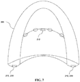
- the first diaphragm has an edge area enlarged to locate at least one of stimulation elements for stimulating the target region of the skin and sensing elements for sensing the state of the target region of the skin.
- the first diaphragm is provided integrally with the negative pressure cup at the inside of the negative pressure cup or separable from the negative pressure cup, so that in case of the integral structure, the first diaphragm is adjusted in position vertically or up and down to control the maximum degree of deformation of the target region of the skin by the negative pressure, and in case of the separable structure, the first diaphragm is located selectively to block or allow the air flows to effectively transmit the negative pressure.
- the first diaphragm and the second diaphragm have vents formed on a partial or the whole region of the surface thereof in such a manner as to pass air therethrough and thus to form the negative pressure.
- the vents have at least one of shapes such as a line, a circle, a polygon, a character, a symbol, and a plate.
- the first diaphragm has concave and convex elements formed thereon to three-dimensionally shape the deformation of the target region of the skin to a previously set degree when the negative pressure stimulation is applied, so that the target region of the skin is deformed, expanded, or rearranged spatially by means of the concave and convex elements and thus subjected to the negative pressure stimulation.
- the concave and convex elements have at least any one form selected from a cylinder, a sphere, a square pyramid, and a triangular pyramid, so that partial deformation of the target region of the skin is adjusted to an intended degree.
- the first diaphragm or the second diaphragm has the stimulation elements for applying stimulation to the target region of the skin or the sensing elements for sensing the state of the target region of the skin.
- the vents serve as paths through which the stimulation generated from the stimulation elements reach directly the target region of the skin or serve as paths through which the state of the target region of the skin is sensed, and higher negative pressure stimulation through the region where the vents are formed is applied to the target region of the skin.
- the first diaphragm and the second diaphragm have the stimulation elements and the sensing elements disposed alone or in combination of two or more elements, the stimulation elements being at least one selected from an electrical stimulation element, a light stimulation LED element, a thermal stimulation element, and a laser element, and the sensing elements being at least one selected from a temperature sensor, an impedance sensor, a blood flow sensor, and a pressure sensor.
- the three-dimensional composite stimulator module further includes a controller for controlling the intensity of the negative pressure according to the time and controlling the other stimulation elements and the sensing elements.
- both of the temporal three-dimensional stimulation through the controller and the spatial three-dimensional stimulation through the concave and convex elements are applied to the target region of the skin.
- FIG. 1 shows a basic structure of a negative pressure cup according to the present invention, wherein the negative pressure cup is configured to have a single diaphragm;
- FIG. 2 shows a separation structure of the first diaphragm of the negative pressure cup according to the present invention
- FIG. 3 shows a basic structure of a negative pressure cup according to the present invention, wherein the negative pressure cup is configured to have multiple diaphragms;
- FIG. 4 shows air flows (or negative pressure transmission paths) in the negative pressure cup according to the present invention
- FIGS. 5 and 6 show stimulation elements and sensing elements located on the diaphragm of the negative pressure cup according to the present invention
- FIG. 7 shows the stimulation elements and the sensing elements located on the negative pressure cup according to the present invention, wherein the edge of the first diaphragm is enlarged;
- FIGS. 8 and 9 show the first diaphragm having a circular shape when viewed from the below thereof, wherein vents and concave and convex elements have various shapes, sizes, and numbers;
- FIGS. 10 and 11 show the first diaphragm having a square shape when viewed from the below thereof, wherein vents and concave and convex elements have various shapes, sizes, and numbers;
- FIGS. 12 and 13 show the first diaphragm viewed from the below thereof, wherein electrical stimulation elements, vents and concave and convex elements have various shapes, sizes, and numbers;
- FIGS. 14 and 15 show the first diaphragm viewed from the below thereof, wherein stimulation elements, sensing elements, vents and concave and convex elements have various shapes, sizes, and numbers;
- FIGS. 16 and 17 show the first diaphragm viewed from the below thereof, wherein stimulation elements have various sizes and formation positions;
- FIGS. 18 and 19 show the first diaphragm viewed from the below thereof, wherein the size and shape of the stimulation element are the same as those of the first diaphragm;
- FIG. 20 a is a schematic figure showing the deformation and three-dimensional rearrangements of the skin and subcutaneous tissues under the negative pressure stimulation in the conventional practice;
- FIG. 20 b is a schematic figure showing the deformation and three-dimensional rearrangements of the skin and subcutaneous tissues under the negative pressure stimulation according to the present invention.
- FIG. 21 shows a diagram of the skin and subcutaneous tissues that are the therapeutic targets of the present invention.
- FIGS. 22 to 24 show a variety of surface shapes of the first diaphragm according to the present invention.
- FIGS. 25 and 26 show the first diaphragm adjusted in height, wherein the first diagram is located by a long distance from the skin surface, and otherwise, the negative pressure stimulation is applied collectively to a small target region;
- FIG. 27 shows a configuration of a three-dimensional negative pressure stimulator according to the present invention
- FIG. 28 shows the negative pressure stimulation generated from skin
- FIG. 29 shows a configuration between a controller and other parts in the three-dimensional negative pressure stimulator according to the present invention.
- a three-dimensional negative pressure stimulator module capable of performing customized composite stimulation for improving skin functions
- a three-dimensional composite stimulator module which is a cosmetic and medical device that applies three-dimensional negative pressure stimulation as well as composite stimulation such as electric current stimulation, light stimulation, and thermal stimulation, which is helpful in improving the skin functions, to the skin compositively, and further has a function of sensing the state of the skin, thereby performing an optimized and individualized stimulation to the skin.
- a three-dimensional composite stimulator 10 which has a concave single or multiple diaphragm structures, applies three-dimensional negative pressure stimulation through composite concave and convex elements and vents formed along a concave semispherical surface of the first diaphragm 201 as a surface close to the skin, and diaphragms of a negative pressure cup 200 effectively transmit negative pressure to the first diaphragm 201 as the surface close to the skin through their respective vents, collectively or distributedly. Further, stimulation elements and sensing elements are disposed supportedly against the diaphragms.
- multi-dimensional composite stimulation such as three-dimensional negative pressure stimulation, micro current stimulation, light stimulation, thermal stimulation and so on, which effectively changes the three-dimensional arrangements of the skin or subcutaneous tissues, is applied stably over a large area, and the state of the skin is monitored through the sensing elements including an impedance sensor, a temperature sensor, a blood flow sensor, a pressure sensor and the like to optimize the composite stimulation to the current state of an individual's skin state, thus effectively achieving the expected effects in skin care.
- an impedance sensor a temperature sensor, a blood flow sensor, a pressure sensor and the like
- the three-dimensional composite stimulator module according to the present invention is provided with the negative pressure cup 200 .
- the negative pressure cup 200 is classified into a cupping cup and a suction cup, but it is not limited thereto. Only if stimulators apply stimulation to the skin by means of negative pressure, they may be within the technological scope of the present invention.
- the negative pressure cup 200 according to the present invention largely includes the first diaphragm 201 and the third diaphragm 203 .
- the third diaphragm 203 is a housing or body of the negative pressure cup 200 and semispherical or concave on a whole shape thereof.
- the third diaphragm 203 is called a housing.
- the first diaphragm 201 is located inside the housing 203 and is semispherical or concave on a whole shape thereof. According to another example, as shown in FIG. 2 , the first diaphragm 201 is separable from the housing 203 . Additionally, as shown in FIG. 3 , the second diaphragm 202 is located above the first diaphragm 201 and is semispherical, concave, convex, or flat on a whole shape thereof. If necessary, accordingly, additional diaphragms may be located above the second diaphragm 202 or between the first diaphragm 201 and the second diaphragm 202 inside the housing 203 .
- the negative pressure cup 200 is provided with the first diaphragm 201 and the housing 203 , it has a single diaphragm structure, and if the negative pressure cup 200 is provided with the first diaphragm 201 , the second diaphragm 202 , and the housing 203 , it has a multiple diaphragm structure.
- the housing 203 , the first diaphragm 201 and the second diaphragm 202 are made of a metal material (hard or semi-hard material) like stainless steel.
- the first diaphragm 201 is brought into direct contact with skin, and therefore, it may be made of a soft material, not hard material, if desirable. If the first diaphragm 201 is semispherical, advantageously, it produces negative pressure, effectively comes into contact with the skin, and applies a variety of three-dimensional negative pressure stimulation to the skin.
- FIG. 1 is a bottom view showing the semispherical first diaphragm 201 providing a skin contact surface.
- the first diaphragm 201 is located along the transmitting path of the negative pressure to a target region (for example, the skin or subcutaneous tissues, which will be referred to as the skin), for example, on the intermediate paths of air flows 101 , 102 and 103 as shown in FIG. 4 .
- the first diaphragm 201 includes vents 204 and concave and convex elements 207 adapted to effectively change the three-dimensional shape of the skin.
- Each diaphragm in the single diaphragm structure or in the multiple diaphragm structure has the vents 204 , 205 and 206 formed as air flow ventilation holes (or air holes, or vents), and the first diaphragm 201 further includes the concave and convex elements 207 .
- the first diaphragm 201 includes stimulation elements 210 or sensing elements 230 , without having the concave and convex elements 207 .
- the first diaphragm 201 desirably includes the concave and convex elements 207 so as to effectively change the three-dimensional shape of the skin when the negative pressure is applied to the skin.
- the first diaphragm 201 and the second diaphragm 202 have the vents 204 and 205 having various sizes, shapes, formation positions and numbers thereof, and the first diaphragm 201 has the concave and convex elements 207 having various sizes, shapes, formation positions and numbers thereof on the skin contact surface thereof.
- FIG. 1 shows a basic structure of the negative pressure cup 200 according to the present invention.
- the first vents 204 and the concave and convex elements 207 are formed on the first diaphragm 201 contacted with the skin or close to the skin.
- the skin comes into close contact with the concave surface of the first diaphragm 201 and the concave and convex elements 207 formed on the surface of the first diaphragm 201 , and the first vents 204 are the points at which the negative pressure is transmitted additionally to the skin contact surface of the first diaphragm 201 .
- the negative pressure transmitted from the region above the first diaphragm 201 is strongly transmitted directly to the skin around the vents 204 (direct transmission), and the negative pressure transmitted through the vents 204 is indirectly transmitted to the skin contact surface of the first diaphragm 201 (indirect transmission).
- the negative pressure is applied collectively and distributedly to the first diaphragm 201 through the first vents 204 , thus transmitting the negative pressure stimulation to the skin. That is, as shown in FIGS. 8 to 11 , the formation positions of the vents 204 are different, thus allowing the negative pressure stimulation to be collected to any one skin region or distributed over the whole skin region.
- the first diaphragm 201 and the second diaphragm 202 are semispherically formed inside the housing 203 . Particularly, the first diaphragm 201 prevents the skin from being deformed excessively when the negative pressure stimulation is applied to the skin (See FIG. 20 b ).
- the first diaphragm 201 has the semispherical shape in such a manner as to control the distance from the skin to the first, thus preventing any excessive deformation of the skin, and accordingly, the skin is physically limitedly deformed and protrudes (limited degree of the maximum deformation) only within the optimal range previously set according to the degree of concavity of the first diaphragm 201 and the surface shape (for example, a saw tooth or wave shape) of the first diaphragm 201 .
- the skin is deformed and protrudes only within the limited range of deformation offered by the semispherical structure and surface shape of the first diaphragm 201 , thus evading such risk that the skin and subcutaneous tissues are excessively deformed and adverse reactions like venous bleeding occur when the negative pressure stimulation to the skin is excessive as is often the case of conventional practice, as shown in FIG. 20 a.
- the whole deformation of the skin and subcutaneous tissues caused by the negative pressure stimulation is not effectively controlled, with inevitable risk of adverse reactions like post-inflammatory hyperpigmentation. If the negative pressure stimulation is applied excessively, further, the deformation of the skin and subcutaneous tissues is also induced excessively, so that the skin and subcutaneous tissues may be congested or bleed.
- the negative pressure cup 200 Under the negative pressure cup 200 according to the present invention as shown in FIG. 20 b , contrarily, even if the negative pressure stimulation is applied to the maximum, the maximum degree of deformation of the skin is effectively controlled within the limit of the concave shape of the first diaphragm 201 and the surface shape thereof, thus putting aside any risk as in the conventional practice. Further, the first diaphragm 201 and the second diaphragm 202 serve as supports to the concave and convex elements 207 , the stimulation elements 210 , and the sensing elements 230 as will be discussed later. Accordingly, the negative pressure stimulation is applied to the skin having the same area as the first diaphragm 201 .
- the concave and convex elements 207 having various shapes are located along the surface of the first diaphragm 201 , and then, the vents 204 are formed therealong, so that when the skin and subcutaneous tissues are expanded or rearranged in a three-dimensional space, the three-dimensional stimulation is applied spatially. Further, the intensity of the negative pressure stimulation is continuously controlled through a controller 430 as will be discussed later throughout the period of stimulation, thus applying three-dimensional negative pressure stimulation temporally.
- the three-dimensional deformation of the skin and subcutaneous tissues and resultant rearrangement of the tissues is effectively controlled to apply optimized stimulation to various targets such as keratin, melanocyte, collagen, elastin fibers, hair follicles, sweat glands, blood vessels, lymph, and nerves, which are stimulated through the deformation of the tissues thereof, thus advantageously achieving the expected effects in the skin.
- targets such as keratin, melanocyte, collagen, elastin fibers, hair follicles, sweat glands, blood vessels, lymph, and nerves, which are stimulated through the deformation of the tissues thereof, thus advantageously achieving the expected effects in the skin.
- the state of the skin is continuously monitored by the sensing elements, and the information on the current state of the skin is transmitted to the controller 430 , so that the negative pressure stimulation can be effectively controlled and optimized by the controller 430 .
- the skin coming into contact with the first diaphragm 201 is deformed in such a manner as to be brought into complete or almost complete contact with the first diaphragm 201 .
- higher intensity stimulation of negative pressure is applied to the skin area facing the vents 204 , and the deformation of the skin is controlled variously according to the shapes of the three-dimensional concave and convex elements 207 located along the surface of the first diaphragm 201 , thus allowing the deformation and rearrangements of the skin tissues to be formed variously.
- diverse stimulations such as three-dimensional deformation, expansion, or rearrangement of the tissues are applied spatially to the components (See FIG.
- the intensity of the negative pressure stimulation is controlled through the controller 430 during the period of negative pressure stimulation, and accordingly, the three-dimensional structure of the skin and subcutaneous tissues such as collagen, elastin fibers, and so on are effectively stimulated during the period of negative pressure stimulation.
- the negative pressure stimulation is effectively applied to prevent any adhesions or atrophy of the collagen and elastin fibers.
- sensory receptors like Meissner's corpuscle, Pacinian corpuscle, and so on are stimulated through the tissue deformation thereof.
- hair follicles, sweat glands, sebaceous glands, blood vessels, lymph, nerves, keratin cells, melanocyte, and fat cells are effectively stimulated by three-dimensional deformation and re-arrangement.
- the suction device or cupping device in the conventional practice applies just a simple negative pressure stimulation to the skin.
- the three-dimensional stimulation is applied spatially by means of the formation of the overall shape of the diaphragm 201 , the concave and convex elements 207 having various shapes, and the vents 204 formed on the surface of the first diaphragm 201 , and further, it is applied temporally by means of the controller 430 , thus effectively achieving the stimulation of three-dimensional rearrangement of the components of the skin and subcutaneous tissues.
- the first diaphragm 201 is semispherical or concave on the whole shape thereof, so that the skin is three-dimensionally deformed to the internal direction of the first diaphragm 201 when the negative pressure stimulation is applied and thus comes into close contact with the first diaphragm 201 and its concave and convex elements 207 . Accordingly, as shown in FIG. 20 b , the skin corresponds to the concave shape of the first diaphragm 201 and protrudes toward the concave side of the first diaphragm 201 when the negative pressure stimulation is applied.
- the first diaphragm 201 has a circular or polygonal sectional shape. At this time, the polygonal section is desirably square. As shown in FIGS.
- the skin contact surface of the first diaphragm 201 desirably has a shape of a saw tooth, a cylinder or a wave, and additionally, it has various shapes of a plane, a pulse and others.
- the three-dimensional deformation of the skin is variously controlled according to the shapes of the skin contact surface of the first diaphragm 201 . As shown in FIG.
- the edge region of the first diaphragm 201 which comes into contact with the skin, is expanded, and irrespective of the application of the negative pressure stimulation, the stimulation elements 210 and the sensing elements 230 are located on the edge region of the first diaphragm 201 , so that separate stimulation is applied to the skin and the skin state is fed back. Accordingly, the edge region of the first diaphragm 201 is expanded to allow the stimulation elements 210 and the sensing elements 230 to be located thereon.
- the first diaphragm 201 has the vents 204 formed thereon, and if necessary, it further has the concave and convex elements 207 , the stimulation elements 210 , and the sensing elements 230 . Additionally, the first diaphragm 201 is heated by electricity to allow blood circulation to be improved, thus optimizing the composite stimulation effects of the negative pressure and the thermal stimulation.
- the second diaphragm 202 is located above the first diaphragm 201 and other diaphragms are sequentially located above or under the second diaphragm 202 .
- the second diaphragm 202 is semispherical, concave, convex, or flat on a whole shape thereof and does not come into direct contact with the skin, unlike the first diaphragm 201 . Further, the second diaphragm 202 is located above the first diaphragm 201 and flat on a whole shape thereof. As shown in FIG.
- the second diaphragm 202 has the second vents 205 formed thereon, and if necessary, it serves as a support for the stimulation elements 210 and the sensing elements 230 .
- the edge region of the second diaphragm 202 is expanded to allow the stimulation elements 210 and the sensing elements 230 to be located thereon.
- the first diaphragm 201 and the second diaphragm 202 are located along the path of the air flows (on the transmission paths of the negative pressure) in an upward direction from just above the skin (that is, toward the first diaphragm 201 from the skin).
- the housing 203 is a final diaphragm located at the outermost position of the negative pressure cup 200 and has the third vent 206 formed on the top or side surface thereof, thus finally discharging the air flowing in the upward direction from just above the skin.
- the negative pressure stimulation is applied over a large region of skin.
- the air ventilated through the third vent 206 of the housing 203 is accommodated by the body 400 .
- the surface of the first diaphragm 201 to be contacted with the skin is concave on the whole shape (for example, semispherical) so as to produce the negative pressure, provide efficient contact with the skin, and apply three-dimensional negative pressure stimulation to the skin.
- the first diaphragm 201 has one or more concave and convex elements 207 located on the entire region or a partial region thereof, and the concave and convex elements 207 have one or more shapes selected from a cylinder, a sphere, a square pyramid, a triangular pyramid and so on, so that when the negative pressure stimulation is applied, the degree of the spatial rearrangements of the skin and subcutaneous tissues is controlled to the optimal shape and degree previously set according to the intended purpose of the effects in the skin.
- the intensity of the negative pressure stimulation is continuously controlled by the controller 430 during the period of negative pressure stimulation, so that the temporal control of the three-dimensional stimulation of negative pressure can be effectively performed.
- the variety of stimulation elements 210 and the sensing elements 230 are located on the first diaphragm 201 , the second diaphragm 202 , and the housing 203 .
- the third vents 206 are formed on the top or side surface of the housing 203 as the final diaphragm, thus discharging the air inside the negative pressure cup 200 to the outside.
- the respective diaphragms have the first to third vents 204 , 205 , and 206 adapted to transmit the negative pressure to the skin, and the air is finally discharged through the third vents 206 formed on the top or side surface of the housing 203 to the outside of the triple diaphragms.
- the respective diaphragms have semispherical, planar, or other shapes, and they have various sizes and formation positions.
- the first diaphragm 201 has a concave shape.
- FIG. 1 shows the basic structure of the negative pressure cup 200 and FIG. 3 shows the triple diaphragm structure thereof.
- the basic structure of the negative pressure cup 200 has the first diaphragm 201 and the housing 203 , and the triple diaphragm structure thereof has the first diaphragm 201 , the second diaphragm 202 , and the housing 203 .
- the sizes, shapes and positions of the vents are differently formed.
- the air inside the negative pressure cup 200 is finally discharged through the third vents 206 formed on the top or side surface of the housing 203 as the final diaphragm, thus allowing the negative pressure stimulation to be applied to the surface of the skin.
- the first diaphragm 201 which comes into direct contact with the skin, is coupled to the inside of the housing 203 , as shown in FIG. 1 , or is separated from the housing 203 as shown in FIG. 2 . If the first diaphragm 201 is separated from the housing 203 , that is, the first diaphragm 201 is coupled or connected to the housing 203 by means of first coupling elements 310 and second coupling elements 320 .
- the first coupling elements 310 and the second coupling elements 320 are provided along the partial range of or the whole range of the circumference of the housing 203 and have a structure of selectively blocking and allowing the flow of air so as to effectively transmit the negative pressure.
- the first diaphragm 201 is closed by the coupling elements to permit the flow of air to be formed only through the first vents 204 of the first diaphragm 201 , so that the negative pressure stimulation is applied to the skin facing the first diaphragm 201 .
- the first coupling elements 310 and the second coupling elements 320 are formed of screws, screw grooves, and rubber packings.
- the first diaphragm 201 in the separable structure from the housing 203 has a module type, and accordingly, it is easily detachable from the housing 203 .
- the structure of the first diaphragm 201 is made within the technological scope of the present invention.
- the formation of the separable first diaphragm 201 from the housing 203 gives a variety of advantages. Diverse types of the first diaphragm 201 may be used by attaching to the same housing 203 , ensuring individualized and multi-purpose application of the negative pressure device. In addition, under the coupling structure of the first diaphragm 201 , that is, the same negative pressure cup 200 is used for every patient, and accordingly, since the first diaphragm 201 comes into direct contact with the skin, sanitary problems happen.
- the first diaphragm 201 has a module type under the separable structure from the housing 203 , it is easily replaced after use, which is favorable from the sanitary point of view in that only the first diaphragm rather that the whole structure of the cupping cup can be easily replaced with a new one after it has offered direct contact with the skin. Furthermore, since the first diaphragm 201 has a module type under the separable structure from the housing 203 , it is easily detachable from the housing 203 , so that when the first diaphragm 201 is defective, only the first diaphragm 201 is exchanged with new one, which is more economical.
- the first diaphragm 201 is separable from the negative pressure cup 200 , and in the state where the separated first diaphragm 201 is first placed on the target area of the skin, after that, the negative pressure cup 200 is approached to and is connected to the first diaphragm 201 to apply the three-dimensional negative pressure stimulation to the skin.
- This form of application offers a practical and efficient procedure in such case as the target area of the skin and the type of the first diaphragm should be specifically selected.
- the most appropriate type of the first diaphragm 201 and the specific contact site of the skin can be efficiently selected by trying with a separated first diaphragm.
- FIG. 1 shows a single diaphragm structure wherein the first diaphragm 201 and the housing 203 are provided
- FIG. 3 shows a multiple diaphragm structure wherein the first diaphragm 201 , the second diaphragm 202 , and the housing 203 are provided.
- the second diaphragm 202 is located above the first diaphragm 201 coming into direct contact with the skin
- the housing 203 as the final diaphragm is located above the second diaphragm 202 .
- Each diaphragm is made of a hard or semi-hard material adapted to allow the concave and convex elements 207 , the stimulation elements 210 , and the sensing elements 230 to be located thereon, and further has the respective vents 204 , 205 and 206 formed thereon, so that the negative pressure is transmitted through the vents finally to the relatively large area of the skin.
- the first diaphragm 201 is made to a single semispherical shape, and otherwise, various module type first diaphragms are made and coupled or fixed to the inside of the housing 203 .
- various module type first diaphragms are made and coupled or fixed to the inside of the housing 203 .
- a plurality of semispherical mesh frames are made and fixed or coupled to the inside of the housing 203 , while having a given distance from each other with 203 , thus forming the semispherical first diaphragm 201 .
- the mesh holes become the first vents 204 .
- the whole concave shape of the first diaphragm 201 is adjusted to effectively limit the degree of deformation of the skin or subcutaneous tissues induced by the negative pressure stimulation, and further, the respective diaphragms are made of a hard or semi-hard material adapted to allow the stimulation elements 210 and the sensing elements 230 to be located thereon.
- the air flows producing the negative pressure are formed in an upward direction of the negative pressure cup 200 from just above of the skin.
- the respective air flows 101 , 102 and 103 pass through the first to third vents 204 , 205 and 206 of the first to third diaphragms 201 , 202 and 203 and are then accommodated to the body 400 . Accordingly, the air inside the negative pressure cup 200 is discharged to the body 400 , and the air flows form the transmission paths of the negative pressure.
- the first diaphragm 201 has one or more concave and convex elements 207 located on the entire region or a partial region thereof, and the concave and convex elements 207 have one or more shapes selected from a cylinder, a sphere, a square pyramid, a triangular pyramid and so on.
- the first vents 204 are formed at the positions wherein the negative pressure is transmitted more intensively than other positions (for example, the skin contact surface of the first diaphragm 201 , thus allowing the collagen fibers and elastin fibers of the skin and subcutaneous tissues facing the vents to be more intensively expanded and rearranged in the three-dimensional space through the negative pressure stimulation.
- the intensity of the negative pressure stimulation is controlled through the controller 430 as time has passed, thus applying the three-dimensional negative pressure stimulation temporally.
- the maximum degree of deformation and protrusion of the skin and subcutaneous tissues is physically controlled within an appropriate limit by the semispherical or concave shape of the first diaphragm 201 , thus effectively minimizing the risk of adverse reaction like excessive skin deformation due to the excessive stimulation of negative pressure stimulation or post-inflammatory hyperpigmentation related thereto.
- the conventional suction or cupping cups that is, if the individual's skin to which the negative pressure stimulation is applied and his or her physical characteristics are relatively weak or hypersensitive, or otherwise, if the negative pressure stimulation is excessive considering the individual characteristics of the subject, there are risk of excessive deformation of the skin and subcutaneous tissues and adverse reaction like venous bleeding.
- the skin and subcutaneous tissues are deformed or protrude only to an appropriate degree offered by the semispherical or concave structure of the first diaphragm 201 .
- the sizes, shapes, and the degrees of concavity of the first diaphragm 201 are designed to offer a three-dimensional deformation of the skin tissues appropriate for such effects as anti-wrinkle, improved blood flow, whitening, moisturizing, and so on, and also, the intensity of the negative pressure stimulation is controlled by the controller 430 , thus applying an optimized stimulation of negative pressure to the skin and subcutaneous tissues.
- light stimulation generated from the stimulation elements 210 located on the second diaphragm 202 for example, light stimulation LED elements 212 are irradiated to the skin underneath the first diaphragm 201 through the first vents 204 of the first diaphragm 201 .
- the degree of deformation in the skin is hard to control. Accordingly, it is basically hard to optimize the composite stimulation of light applied together with the negative pressure stimulation, and further, there also exists a risk of adverse reactions due to poor control of the degree of skin deformation.
- the points and their distances at which the light stimulation generated from the stimulation elements 210 located on the second diaphragm 202 arrive are infallibly calculated considering the degree of deformation of the skin offered by the first diaphragm 201 , so that optimal intensity of the light stimulation are effectively calibrated.
- electrical stimulation elements 211 are located on the first diaphragm 201 in such a manner as to come into direct contact with the skin to apply the stimulation to the skin.
- the first diaphragm 201 has the first vents 204 and the concave and convex elements 207
- the second diaphragm 202 has the second vents 205
- the housing 203 has the third vents 206 .
- the first vents 204 and the second vents 205 are ventilation holes (or air holes), through which the negative pressure stimulation is transmitted to the skin. Particularly, the intensity of the negative pressure stimulation is higher in the skin region facing the vents than other skin regions.
- the first to third vents 204 to 206 serve as paths for such stimulations as generated from the stimulation elements 210 disposed on the second diaphragm 202 and the housing 203 to approach to the skin, and serve as paths or windows of the sensing elements 230 disposed on the second diaphragm 202 and the housing 203 to monitor the state of the skin.
- the negative pressure cup 200 according to the present invention is provided with the stimulation elements 210 and the sensing elements 230 , thus conducting such functions as composite stimulation and composite monitoring performed simultaneously.
- the first vents 204 and the second vents 205 are formed along the concave semispherical surfaces of the first diaphragm 201 and the second diaphragm 202 , and the third vents 206 are formed on the top or side surface of the housing 203 .
- the first to third vents 204 to 206 have shapes of fine dot-like holes, so that the corresponding diaphragms look like nets, and in addition, they may show various shapes such as a line, a circle, a polygon, a character, a symbol, and a plate.
- the third vents 206 through which the air inside of the negative pressure cup 200 is finally discharged, are formed on the top or side surface of the housing 203 .
- the first to third vents 204 to 206 generally serve as the ventilation holes through which the air passes, and they may have various shapes. According to the present invention, therefore, the shapes of the first to third vents 204 to 206 are not limited specifically.
- the first diaphragm 201 has the concave and convex elements 207 .
- the partial deformation of the skin is adjusted to the optimal degree of deformation designed previously, upon the application of the negative pressure stimulation to the skin.
- the deformation of the skin can be three-dimensionally shaped with diverse positions and shapes of the concave and convex elements 207 .
- one or more concave and convex elements 207 are located on the entire region or a partial region thereof (See FIGS. 8 to 11 ), and the concave and convex elements 207 have one or more shapes selected from a cylinder, a sphere, a square pyramid, a triangular pyramid and so on.
- the deformation of the skin and subcutaneous tissues is limited to an appropriate degree according to the degree of concavity in the whole shape of the first diaphragm 201 , thus effectively minimizing any risk of adverse reactions like post-inflammatory hyperpigmentation.
- the first vents 204 of various sizes, shapes, formation positions, and numbers, and the concave surface of the first diaphragm 201 are variously deformed in three-dimensional forms, thus applying efficient stimulation for the improvement of the functions of the skin.
- the intensity of negative pressure is continuously controlled through the controller 430 during the negative pressure stimulation, which control is effectively modulated with reference to the information on the current state of the individual's skin monitored by the sensing elements 230 , so that customized and individualized stimulation of three-dimensional negative pressure offers an optimal stimulation for the improvement of the skin functions.
- the sensing elements 230 include a temperature sensor 231 , an impedance sensor 232 , a blood flow sensor 233 , and a pressure sensor 234 , and they are mounted on the diaphragms of the negative pressure cup 200 or formed integrally therewith. If they are mounted thereon, they are located on specific regions of the diaphragms. If they are formed integrally therewith, the circuits for driving the sensing elements 230 are also formed integrally with the diaphragms.
- the impedance sensor 232 is adapted to measure impedance in the skin contact area with the cupping device and has an amplifier if needed.
- the temperature sensor 231 is used individually or together from or with a non-contact infrared sensor or a contact sensor and serves to measure the temperature of the skin surface or the surrounding temperature. At this time, an element like an ultra-small thermistor or an ultra-precision thermocouple is used to measure the temperature of the skin.
- the blood flow sensor 233 includes an LED light source and a photodiode and serves to convert the optical data reflecting the amount of blood flowing along the blood vessel in the target area of the skin into a current or voltage signal. The LED light source is used also for the light stimulation.
- the pressure sensor 234 serves to measure the pressure of the negative pressure cup 200 so as to feed back the state of the negative pressure.
- the stimulation sensors 210 include the electrical stimulation elements 211 , the light stimulation LED elements 212 , and the thermal stimulation elements.
- the electrical stimulation elements 211 are formed of electrode plates with different potentials. A plurality of electrode plates may be located so as to allow micro current to be uniformly applied.
- the LED light sources of the light stimulation LED elements 212 are used with the LEDs having wavelength bands effective in the skin stimulation, and at this time, one or more wavelength bands are provided in a single or plural combination thereof. Light emitting elements are provided as the thermal stimulation elements.
- the light stimulation LED elements 212 are used for the light stimulation.
- laser elements have very limited irradiation points when compared with the LED elements 212 , so that it is hard to conduct the composite stimulation over the whole internal region of the skin contact surface of the negative pressure cup 200 . Accordingly, the light stimulation is usually applied through the LED elements, but the laser elements may be used if needed.
- FIG. 5 shows the stimulation elements 210 of the first diaphragm 201 and the second diaphragm 202 .
- the stimulation elements 210 have various kinds, sizes, shapes, formation positions and numbers thereof, and as shown in FIG. 5 , the electrical stimulation elements 211 are located on the first diaphragm 201 , while the light stimulation elements 212 are being located on the second diaphragm 202 .
- the conventional negative pressure and composite stimulation device disadvantageously, it is very limited in locating the stimulation elements within the cupping cup, and otherwise, when other stimulation is applied, the negative pressure stimulation is considerably limited.
- the first diaphragm 201 , the second diaphragm 202 , and the housing 203 serve as rigid supports for stimulation elements or sensing elements, so that the stimulation elements 210 can be located on the diaphragms, while having various kinds, sizes, shapes, formation positions and numbers thereof.
- the skin When the negative pressure stimulation is applied to the skin via the first diaphragm 201 , the skin is deformed and protrudes to come into close contact with the first diaphragm 201 . At this time, the micro current stimulation through the electrical stimulation elements 211 of the first diaphragm 201 and the light stimulation generated from the light stimulation LED elements 221 of the second diaphragm 202 are applied to the skin through the first vents 204 of the first diaphragm 201 , thus allowing the skin to be stimulated.
- the area to which the electrical stimulation is applied are so limited that the electrical stimulation is applied just to the circular rim of the contact area facing the negative pressure cup, or the points to which the light stimulation is applied are very limited, so that the points to which the electrical stimulation or the light stimulation are applied disadvantageously do not correspond to the relatively large region to which the negative pressure stimulation is applied.
- the first vents 204 with various sizes, shapes, formation positions and numbers are formed on the first diaphragm 201 , and accordingly, the electrical stimulation and the light stimulation are applied over the whole region of the skin contact surface as well as the circular rim of the contact area facing the concave negative pressure cup 200 , so that the negative pressure stimulation, the electrical stimulation, and the light stimulation are applied over almost the same region as the first diaphragm 201 . That is, advantageously, the composite stimulation is applied stably to the whole region facing the first diaphragm 201 . Further, the skin state is monitored by the sensing elements 230 , and accordingly, various stimulation is adjusted and applied reflecting the current state of the skin of the individual, thus achieving a customized stimulation over the whole region of the skin.
- FIG. 6 shows the sensing elements 230 located on the respective diaphragms.
- the sensing elements 230 are varied in kinds, sizes, shapes, formation positions and numbers thereof.
- it is very limited in locating the sensing elements within the cupping cup, and otherwise, the sensing elements are located, while the negative pressure stimulation is being limited.
- the first diaphragm 201 , the second diaphragm 202 and the housing 203 serve as rigid supports for the sensing elements and the vents of the respective diaphragms serve to gently transmit the negative pressure through the respective diaphragms, so that the sensing elements can be located on the respective diaphragms to monitor the current state of the skin through the vents as windows to the skin, without having any limitation in the application of the negative pressure stimulation.
- the risk that the efficiency of the negative pressure stimulation is decreased or the negative pressure stimulation is distorted is minimalized by adopting such strategy that the sensing elements are firmly located onto the diaphragm and the sensing elements directly face the skin through the vents. As shown in FIG.
- the temperature sensor 231 and the impedance sensor 232 are located on the first diaphragm 201 , the blood flow sensor 233 on the second diaphragm 202 , and the pressure sensor 234 on the housing 203 . If necessary, however, the arrangements of the stimulation elements 210 and the sensing elements 230 as shown in FIGS. 5 and 6 may be freely changed.
- the first vents 204 of the first diaphragm 201 pair up or mix with the concave and convex elements 207 , as shown in FIGS. 8 and 9 .
- FIG. 8 shows the first vents 204 and the concave and convex elements 207 formed on a portion of the region of the first diaphragm 201
- FIG. 9 shows the first vents 204 and the concave and convex elements 207 formed on the whole region of the first diaphragm 201 .
- the first diaphragm 201 as shown in FIGS. 8 and 9 has a circular sectional shape, and that as shown in FIGS. 10 and 11 has a square sectional shape.
- the formation positions of the first vents 204 and the concave and convex elements 207 as shown in FIGS. 10 and 11 are the same as those in FIGS. 8 and 9 , and the sectional shape of the first diaphragm 201 as shown in FIGS. 10 and 11 is not different from that as shown in FIGS. 8 and 9 .
- the first vents 204 and the concave and convex elements 207 can have various sizes, shapes, formation positions and numbers thereof.
- FIGS. 12 and 13 show various arrangements of the stimulation elements 210 on the first diaphragm 201 .
- the stimulation elements 210 having various sizes, shapes, formation positions and numbers thereof are located, while avoiding the positions on which the first vents 204 are formed.
- FIGS. 14 and 15 show various arrangements of the stimulation elements 210 and the sensing elements 230 on the first diaphragm 201 .
- the electrical stimulation elements 211 , the temperature sensor 231 , the impedance sensor 232 , and the blood current sensor 233 having various sizes, shapes, formation positions and numbers thereof are located on the first diaphragm 201 , while avoiding the positions on which the first vents 204 are formed.
- FIGS. 16 and 19 show various sizes and positions of the stimulation elements 210 on the first diaphragm 201 .
- the electrical stimulation elements 211 having various sizes, shapes, formation positions and numbers thereof are located on the first diaphragm 201 , while avoiding the positions on which the first vents 204 are formed.
- FIGS. 18 and 19 show the electrical stimulation elements 211 having the same sizes and shapes as the first diaphragm 201 . That is, the whole region of the first diaphragm 201 except for the first vents 204 serves as the electrical stimulation elements 211 .
- FIGS. 25 and 26 show various positions of the first diaphragm 201 .
- the first diaphragm 201 is separable from the housing 203 , and after the first diaphragm 201 is brought into contact with the target skin region, in this case, the negative pressure stimulator or the cupping cup or suction cup for negative pressure stimulation comes into contact with the top of the first diaphragm 201 or the periphery thereof, so that upon the application of the negative pressure stimulation, the negative pressure stimulation can be applied three-dimensionally to the skin with the help of the first diaphragm 201 . Further, as shown in FIG.
- the first diaphragm 201 is located by a relatively long distance from the skin surface, so that a given distance from the whole region of the target skin is maintained to accommodate deformation of the skin, and as shown in FIG. 26 , only a given region of the first diaphragm 201 is located by a relatively long distance from the skin surface, so that the negative pressure stimulation can be applied collectively to a relatively small region of the target skin. According to the desired purposes, therefore, the distance between the first diaphragm 201 and the target skin is increased appropriately, and otherwise, the negative pressure stimulation is applied collectively to the relatively small region of the target skin.
- the three-dimensional negative pressure stimulator 10 is configured wherein the body 400 having a USB charger 410 , a manipulator 420 , the controller 430 , a battery 440 , a motor 450 , a fan 460 and a PCB 470 is coupled or connected to the negative pressure cup 200 , thus applying the three-dimensional negative pressure stimulation to the skin.
- the USB charger 410 is a USB terminal for charging the portable three-dimensional negative pressure stimulator 10
- the battery 440 which supplies electricity to the three-dimensional negative pressure stimulator 10 , is a lithium-ion battery.
- the charger and the battery may have various charging methods and battery kinds, while being limited thereto.
- the portable three-dimensional negative pressure stimulator 10 or the fixed type three-dimensional negative pressure stimulator 10 is the stimulator used with normal power.
- the USB charger 410 and the battery 440 as a power supply part receive the power from an external power terminal and supply the power necessary for the operation of the three-dimensional negative pressure stimulator 10 .
- the motor 450 and the fan 460 operate by control signals of the controller 430 to induce the air flows 100 as shown in FIG. 27 , thus allowing the negative pressure to be generated. That is, if the motor 450 and the fan 460 operate, the air flows 100 are induced toward the diaphragms of the negative pressure cup 200 from just above the skin to allow the air to pass through the vents, and next, the air flows 100 are induced toward the body 400 from the negative pressure cup 200 to allow the negative pressure to be generated. If the negative pressure is generated, as shown in FIG. 28 , the skin 20 protrudes toward its protruding directions 21 (or toward the negative pressure cup 200 ), so that it is under the negative pressure stimulation. The intensity of the negative pressure is varied in accordance with the driving speeds of the motor 450 and the fan 460 controlled by the controller 430 .
- the PCB 470 has a variety of elements and circuits disposed thereon so as to drive the USB charger 410 , the manipulator 420 , the battery 440 , the motor 450 , and the fan 460 .
- the manipulator 420 has a variety of buttons mounted thereon, so that the three-dimensional negative pressure stimulator 10 is manipulated by the user, and otherwise, the manipulator 420 includes a touch screen for the manipulation.
- a display (not shown) may be provided to in real time display the state of the three-dimensional negative pressure stimulator 10 according to the manipulation. After a signal sensed through the pressure sensor 234 is inputted to the controller 430 , for example, the intensity of the negative pressure is displayed through the display.
- the controller 430 produces control signals corresponding to the manipulations of the manipulator 420 , controls the driving of the battery 440 , the motor 450 , and the fan 460 according to the produced signals, monitors the state of the skin with the signals received from the sensing elements 230 to perform the feedback control, and transmits the control signal to the stimulation elements 210 to allow the composite stimulation to be applied to the skin. Further, the controller 430 controls the display to allow the current skin state or the state of the three-dimensional negative pressure stimulator 10 to be displayed on the display.
- the controller 430 is configured as follows.
- a current controller controls a quantity of current flowing to the electrical stimulation elements 211 and generates a current waveform to apply the current stimulation to the skin.
- the quantity of current is micro current capable of offering stimulation to the skin.
- the current waveform is a square wave, a sine wave, or an arbitrary wave.
- An LED controller adjusts a quantity of current required for the LED light source.
- the LED controller controls the currents of the LED light source elements, so that the LED light sources having different wavelength bands maintain the same quantity of light as each other.
- the LED controller receives data from an ambient light sensor so as to measure the quantity of light of the light source.
- a negative pressure sensor controls the operations of the driving motor and the fan for absorption. The negative pressure sensor receives the feedback on the value indicating the degree of negative pressure from the pressure sensor.
- the rearrangements, expansion, and formation stimulation of the skin and subcutaneous tissues are applied three-dimensionally through the first diaphragm of the negative pressure cup, the maximum degree of deformation of the skin and subcutaneous tissues is effectively controlled to apply the negative pressure stimulation stably, the composite stimulation is applied through the stimulation elements located supportedly on the respective diaphragms, and the stimulation customized to the individual's skin state is applied through the sensing elements.
- the three-dimensional rearrangements, expansion, and formation stimulation of the skin and subcutaneous tissues are applied through the three-dimensional negative pressure stimulation, and the composite stimulation and the customized stimulation are also provided, thus improving the skin functions.
- the composite stimulation such as the electrical stimulation and the light stimulation through visible light, infrared ray and ultraviolet ray are transmitted to the large skin contact surface, and the states of localized skin and subcutaneous tissues like skin impedance, temperature, blood flow and so on are sensed, while the state of the negative pressure is being monitored by the pressure sensor, so that in addition to the three-dimensional negative pressure stimulation providing optimized deformation and rearrangements of the skin and subcutaneous tissues, the various composite stimulation is customized to the state of the individual's skin.
Landscapes
- Health & Medical Sciences (AREA)
- Life Sciences & Earth Sciences (AREA)
- Engineering & Computer Science (AREA)
- Biomedical Technology (AREA)
- Animal Behavior & Ethology (AREA)
- Veterinary Medicine (AREA)
- Public Health (AREA)
- General Health & Medical Sciences (AREA)
- Pathology (AREA)
- Nuclear Medicine, Radiotherapy & Molecular Imaging (AREA)
- Radiology & Medical Imaging (AREA)
- Biophysics (AREA)
- Physics & Mathematics (AREA)
- Heart & Thoracic Surgery (AREA)
- Physical Education & Sports Medicine (AREA)
- Rehabilitation Therapy (AREA)
- Pain & Pain Management (AREA)
- Epidemiology (AREA)
- Molecular Biology (AREA)
- Surgery (AREA)
- Medical Informatics (AREA)
- Hematology (AREA)
- Dermatology (AREA)
- Cardiology (AREA)
- Physiology (AREA)
- Optics & Photonics (AREA)
- Percussion Or Vibration Massage (AREA)
- Electrotherapy Devices (AREA)
- Massaging Devices (AREA)
- Vascular Medicine (AREA)
- Radiation-Therapy Devices (AREA)
- Anesthesiology (AREA)
- Thermotherapy And Cooling Therapy Devices (AREA)
- Finger-Pressure Massage (AREA)
- Oral & Maxillofacial Surgery (AREA)
- Plastic & Reconstructive Surgery (AREA)
Abstract
Description
Claims (6)
Applications Claiming Priority (2)
| Application Number | Priority Date | Filing Date | Title |
|---|---|---|---|
| KR1020150123090A KR101585151B1 (en) | 2015-08-31 | 2015-08-31 | 3D negative pressure module for tailored multimodal stimulation of skin |
| KR10-2015-0123090 | 2015-08-31 |
Publications (2)
| Publication Number | Publication Date |
|---|---|
| US20170056281A1 US20170056281A1 (en) | 2017-03-02 |
| US10639229B2 true US10639229B2 (en) | 2020-05-05 |
Family
ID=55172913
Family Applications (1)
| Application Number | Title | Priority Date | Filing Date |
|---|---|---|---|
| US15/227,021 Expired - Fee Related US10639229B2 (en) | 2015-08-31 | 2016-08-03 | Three-dimensional negative pressure stimulator module capable of performing customized composite stimulation for improvement of skin functions |
Country Status (5)
| Country | Link |
|---|---|
| US (1) | US10639229B2 (en) |
| JP (2) | JP2017047184A (en) |
| KR (1) | KR101585151B1 (en) |
| CN (1) | CN106473907B (en) |
| WO (1) | WO2017039110A1 (en) |
Families Citing this family (20)
| Publication number | Priority date | Publication date | Assignee | Title |
|---|---|---|---|---|
| KR101877320B1 (en) * | 2016-07-15 | 2018-07-11 | 주식회사 이루다 | Device for moxibustion and acupuncture in oriental medicine using laser and radio frequency |
| CN107019843B (en) * | 2017-06-07 | 2024-02-06 | 柴雪青 | Negative pressure transdermal drug delivery device |
| IT201700101375A1 (en) * | 2017-09-11 | 2019-03-11 | Maurizio Busoni | Device to stimulate skin regeneration |
| KR102214774B1 (en) * | 2018-02-24 | 2021-02-17 | 연세대학교 원주산학협력단 | Cardiovascular and Cerebrovascular Disease Risk Assessment System Using Adsorption Cup Type Blood Flow Measurement Sensor |
| KR102173184B1 (en) * | 2018-02-24 | 2020-11-04 | 연세대학교 원주산학협력단 | Apparatus and method for blood flow change measurement using adsorption cup |
| CN108904978B (en) * | 2018-06-11 | 2021-11-09 | 广州美锐健康产业股份有限公司 | Beauty device based on simulation biological micro-current |
| CN112601810A (en) * | 2018-08-31 | 2021-04-02 | 株式会社资生堂 | Cosmetic method |
| EP3721851A1 (en) * | 2019-04-11 | 2020-10-14 | High Technology Products, S.L.U. | Methods and systems for treatment of skin of a subject |
| KR102285202B1 (en) | 2019-09-24 | 2021-08-04 | 단국대학교 천안캠퍼스 산학협력단 | Personalized mask device using electrical stimulation |
| KR102285203B1 (en) | 2019-09-24 | 2021-08-04 | 단국대학교 천안캠퍼스 산학협력단 | Personalized mask device using ultrasonic wave |
| KR102285201B1 (en) | 2019-09-24 | 2021-08-04 | 단국대학교 천안캠퍼스 산학협력단 | Personalized mask device using chemical solution |
| KR102116334B1 (en) | 2019-09-24 | 2020-05-29 | 단국대학교 천안캠퍼스 산학협력단 | Personalized mask device using multi-wavelength laser |
| KR102344198B1 (en) * | 2020-01-21 | 2021-12-27 | 강상훈 | Portable cupping machine with pressure sensor |
| CN111084909A (en) * | 2020-03-05 | 2020-05-01 | 上海中医药大学 | Intelligent traditional Chinese medicine cupping device |
| TWI718892B (en) * | 2020-03-06 | 2021-02-11 | 財團法人國家衛生研究院 | Light-stimulating vibration massager |
| CN111407941A (en) * | 2020-04-07 | 2020-07-14 | 北京中关村水木医疗科技有限公司 | Skin impedance acquisition device and method and negative pressure monitoring system in cupping device |
| CN111407275B (en) * | 2020-04-07 | 2023-10-17 | 北京中关村水木医疗科技有限公司 | Method and device for monitoring skin condition in cupping device |
| CN111973181B (en) * | 2020-08-24 | 2023-12-08 | 中国科学院上海微系统与信息技术研究所 | Cortical brain electrode integrated with acquisition stimulation function and manufacturing method thereof |
| WO2022082076A1 (en) * | 2020-10-17 | 2022-04-21 | Divergent Med Llc | Cooling system with at least one chamber for localized cooling treatment |
| US20220312934A1 (en) * | 2021-04-05 | 2022-10-06 | Hermes Innovations, LLC | Systems and methods for treating lips and skin |
Citations (20)
| Publication number | Priority date | Publication date | Assignee | Title |
|---|---|---|---|---|
| US6042537A (en) * | 1997-08-13 | 2000-03-28 | Kaiser; Daniel | Method and apparatus for tissue enlargement |
| KR20010056675A (en) | 1999-12-16 | 2001-07-04 | 유유자 | A cap for cupping a boil case |
| US20040236252A1 (en) * | 2001-07-13 | 2004-11-25 | Francesco Muzzi | Apparatus for treating cellulitis by combined methods |
| KR100561333B1 (en) | 2004-04-02 | 2006-03-17 | 임수향 | Portable apparatus for eliminate subcutaneous fat |
| US20060259102A1 (en) * | 2001-12-10 | 2006-11-16 | Michael Slatkine | Method and apparatus for vacuum-assisted light-based treatments of the skin |
| US20070027411A1 (en) * | 2001-08-08 | 2007-02-01 | Engii (2001) Ltd. | System and method for face and body treatment |
| US20080106896A1 (en) * | 2006-11-03 | 2008-05-08 | Biboting International Co., Ltd. | Illumination device for coupling with cup structure |
| KR100913842B1 (en) * | 2009-02-18 | 2009-08-26 | 장태순 | Double massaging tool for massage apparatus |
| US20110112520A1 (en) * | 2009-11-11 | 2011-05-12 | Invasix Corporation | Method and device for fat treatment |
| KR101042837B1 (en) | 2009-08-13 | 2011-06-21 | 연세대학교 산학협력단 | Potable cupping system with laser diode |
| KR101089737B1 (en) | 2009-04-17 | 2011-12-07 | 권용운 | Hand-Set generating low pressure and high frequency |
| US20120150079A1 (en) * | 2009-08-20 | 2012-06-14 | Avner Rosenberg | Method and apparatus for non- invasive aesthetic treatment of skin and sub-dermis |
| US20120253416A1 (en) * | 2011-03-31 | 2012-10-04 | Danny Erez | System and method for fractional treatment of skin |
| KR20130053099A (en) | 2011-11-15 | 2013-05-23 | 한국 한의학 연구원 | Smart cupping treatment device |
| KR200472454Y1 (en) | 2012-03-26 | 2014-04-29 | 에인에이 (주) | Treatment device for skin improvement using light emitting diode with excellent potability |
| US20150057578A1 (en) * | 2012-02-29 | 2015-02-26 | Byung Don Min | Suction opening for vacuum absorption type massage machine |
| US20150283022A1 (en) * | 2013-01-22 | 2015-10-08 | Unispatech Co., Ltd. | Metallic heating/cooling pressure-reduction skin management device |
| US20160128605A1 (en) * | 2013-05-27 | 2016-05-12 | Seb S.A. | Apparatus for Calculating a Parameter of a Skin Surface Area |
| US20160128894A1 (en) * | 2013-05-30 | 2016-05-12 | Koninklijke Philips N.V. | Non-invasive device for rejuvenation of skin tissue using treatment pressure below ambient pressure |
| US20180133499A1 (en) * | 2015-04-14 | 2018-05-17 | Crysanthe, Inc. | System and Method for Selective Treatment of Skin and Subcutaneous Fat Using a Single Frequency Dual Mode Radio Frequency Antenna Device |
Family Cites Families (9)
| Publication number | Priority date | Publication date | Assignee | Title |
|---|---|---|---|---|
| KR850002288Y1 (en) * | 1982-08-19 | 1985-10-15 | 배연성 | Device for cautery and skin motion apparatus |
| JP2006289098A (en) * | 2005-04-12 | 2006-10-26 | Inolase 2002 Ltd | Apparatus for vacuum-assisted light-based treatment of skin |
| US20100030128A1 (en) * | 2005-09-06 | 2010-02-04 | Kazuma Mitsuguchi | Iontophoresis device |
| WO2008059565A1 (en) * | 2006-11-15 | 2008-05-22 | Numax Co., Ltd. | Sucking massage device |
| KR20090065395A (en) * | 2007-12-17 | 2009-06-22 | 주식회사 유니온 메디칼 | A high frequency stimulator which checks the control size between skin tissue and stimulator by the air pressure |
| CN101564343A (en) * | 2008-04-25 | 2009-10-28 | 株式会社丽可医疗器 | Fat remover |
| KR101026295B1 (en) * | 2009-02-18 | 2011-03-31 | 장태순 | Massaging cup having dual structure for massage apparatus |
| JP5696969B2 (en) * | 2013-08-28 | 2015-04-08 | 之一 市川 | Subcutaneous fat reduction device |
| WO2015076597A1 (en) * | 2013-11-21 | 2015-05-28 | 주식회사 하이로닉 | Method and device for treating skin disease |
-
2015
- 2015-08-31 KR KR1020150123090A patent/KR101585151B1/en active IP Right Grant
-
2016
- 2016-04-26 WO PCT/KR2016/004322 patent/WO2017039110A1/en active Application Filing
- 2016-07-22 JP JP2016144494A patent/JP2017047184A/en active Pending
- 2016-08-03 US US15/227,021 patent/US10639229B2/en not_active Expired - Fee Related
- 2016-08-25 CN CN201610726083.1A patent/CN106473907B/en not_active Expired - Fee Related
-
2018
- 2018-07-10 JP JP2018002621U patent/JP3218105U/en not_active Expired - Fee Related
Patent Citations (20)
| Publication number | Priority date | Publication date | Assignee | Title |
|---|---|---|---|---|
| US6042537A (en) * | 1997-08-13 | 2000-03-28 | Kaiser; Daniel | Method and apparatus for tissue enlargement |
| KR20010056675A (en) | 1999-12-16 | 2001-07-04 | 유유자 | A cap for cupping a boil case |
| US20040236252A1 (en) * | 2001-07-13 | 2004-11-25 | Francesco Muzzi | Apparatus for treating cellulitis by combined methods |
| US20070027411A1 (en) * | 2001-08-08 | 2007-02-01 | Engii (2001) Ltd. | System and method for face and body treatment |
| US20060259102A1 (en) * | 2001-12-10 | 2006-11-16 | Michael Slatkine | Method and apparatus for vacuum-assisted light-based treatments of the skin |
| KR100561333B1 (en) | 2004-04-02 | 2006-03-17 | 임수향 | Portable apparatus for eliminate subcutaneous fat |
| US20080106896A1 (en) * | 2006-11-03 | 2008-05-08 | Biboting International Co., Ltd. | Illumination device for coupling with cup structure |
| KR100913842B1 (en) * | 2009-02-18 | 2009-08-26 | 장태순 | Double massaging tool for massage apparatus |
| KR101089737B1 (en) | 2009-04-17 | 2011-12-07 | 권용운 | Hand-Set generating low pressure and high frequency |
| KR101042837B1 (en) | 2009-08-13 | 2011-06-21 | 연세대학교 산학협력단 | Potable cupping system with laser diode |
| US20120150079A1 (en) * | 2009-08-20 | 2012-06-14 | Avner Rosenberg | Method and apparatus for non- invasive aesthetic treatment of skin and sub-dermis |
| US20110112520A1 (en) * | 2009-11-11 | 2011-05-12 | Invasix Corporation | Method and device for fat treatment |
| US20120253416A1 (en) * | 2011-03-31 | 2012-10-04 | Danny Erez | System and method for fractional treatment of skin |
| KR20130053099A (en) | 2011-11-15 | 2013-05-23 | 한국 한의학 연구원 | Smart cupping treatment device |
| US20150057578A1 (en) * | 2012-02-29 | 2015-02-26 | Byung Don Min | Suction opening for vacuum absorption type massage machine |
| KR200472454Y1 (en) | 2012-03-26 | 2014-04-29 | 에인에이 (주) | Treatment device for skin improvement using light emitting diode with excellent potability |
| US20150283022A1 (en) * | 2013-01-22 | 2015-10-08 | Unispatech Co., Ltd. | Metallic heating/cooling pressure-reduction skin management device |
| US20160128605A1 (en) * | 2013-05-27 | 2016-05-12 | Seb S.A. | Apparatus for Calculating a Parameter of a Skin Surface Area |
| US20160128894A1 (en) * | 2013-05-30 | 2016-05-12 | Koninklijke Philips N.V. | Non-invasive device for rejuvenation of skin tissue using treatment pressure below ambient pressure |
| US20180133499A1 (en) * | 2015-04-14 | 2018-05-17 | Crysanthe, Inc. | System and Method for Selective Treatment of Skin and Subcutaneous Fat Using a Single Frequency Dual Mode Radio Frequency Antenna Device |
Also Published As
| Publication number | Publication date |
|---|---|
| JP3218105U (en) | 2018-09-20 |
| WO2017039110A1 (en) | 2017-03-09 |
| CN106473907B (en) | 2020-06-02 |
| KR101585151B1 (en) | 2016-01-13 |
| JP2017047184A (en) | 2017-03-09 |
| US20170056281A1 (en) | 2017-03-02 |
| CN106473907A (en) | 2017-03-08 |
Similar Documents
| Publication | Publication Date | Title |
|---|---|---|
| US10639229B2 (en) | Three-dimensional negative pressure stimulator module capable of performing customized composite stimulation for improvement of skin functions | |
| US11633595B2 (en) | System for variably configurable, adaptable electrode arrays and effectuating software | |
| US11642526B2 (en) | Microcurrent-stimulation-therapy method and apparatus | |
| KR101450762B1 (en) | Method and apparatus for treating and promoting hair growth | |
| US20160206871A1 (en) | Variably configurable, adaptable electrode arrays and effectuating software, methods, and systems | |
| US11878167B2 (en) | Device and method for unattended treatment of a patient | |
| WO2013192582A1 (en) | Device and methods for noninvasive neuromodulation using targeted transcrannial electrical stimulation | |
| KR20190103532A (en) | Multi-functional skin care and treatment device for portable | |
| US20140296838A1 (en) | Radio frequency heating device | |
| WO2018071426A1 (en) | System for variably configurable, adaptable electrode arrays and effectuating software | |
| KR20180074465A (en) | The beauty mediacl device using a radio frequency that can control the high frequency irradiation and humidity adjustment amount | |
| KR20200048734A (en) | Skin care apparatus and skin care method using the same | |
| CN114796855A (en) | Radio frequency system, radio frequency method and beauty device | |
| CN219208739U (en) | Device for the unattended treatment of a patient | |
| WO2018127921A1 (en) | Apparatus and method for skin rejuvenation | |
| US11896816B2 (en) | Device and method for unattended treatment of a patient | |
| AU2023100045A4 (en) | Device and method for unattended treatment of a patient | |
| US20240091547A1 (en) | Device and method for unattended treatment of a patient | |
| KR20230128638A (en) | Non-invasive stimulation device and method | |
| KR20240017261A (en) | Skin massaging apparatus |
Legal Events
| Date | Code | Title | Description |
|---|---|---|---|
| AS | Assignment |
Owner name: SD BIOTECHNOLOGIES CO., LTD., KOREA, REPUBLIC OF Free format text: ASSIGNMENT OF ASSIGNORS INTEREST;ASSIGNORS:YI, TAE-HOO;YIN, CHANG-SHIK;CHUNG, SEUK-HWAN;AND OTHERS;REEL/FRAME:039325/0005 Effective date: 20160715 Owner name: TAEYI LIFESCIENCE INC., KOREA, REPUBLIC OF Free format text: ASSIGNMENT OF ASSIGNORS INTEREST;ASSIGNORS:YI, TAE-HOO;YIN, CHANG-SHIK;CHUNG, SEUK-HWAN;AND OTHERS;REEL/FRAME:039325/0005 Effective date: 20160715 |
|
| STPP | Information on status: patent application and granting procedure in general |
Free format text: NON FINAL ACTION MAILED |
|
| STPP | Information on status: patent application and granting procedure in general |
Free format text: RESPONSE TO NON-FINAL OFFICE ACTION ENTERED AND FORWARDED TO EXAMINER |
|
| STPP | Information on status: patent application and granting procedure in general |
Free format text: FINAL REJECTION MAILED |
|
| STPP | Information on status: patent application and granting procedure in general |
Free format text: DOCKETED NEW CASE - READY FOR EXAMINATION |
|
| STPP | Information on status: patent application and granting procedure in general |
Free format text: NOTICE OF ALLOWANCE MAILED -- APPLICATION RECEIVED IN OFFICE OF PUBLICATIONS |
|
| STCF | Information on status: patent grant |
Free format text: PATENTED CASE |
|
| FEPP | Fee payment procedure |
Free format text: MAINTENANCE FEE REMINDER MAILED (ORIGINAL EVENT CODE: REM.); ENTITY STATUS OF PATENT OWNER: SMALL ENTITY |
|
| LAPS | Lapse for failure to pay maintenance fees |
Free format text: PATENT EXPIRED FOR FAILURE TO PAY MAINTENANCE FEES (ORIGINAL EVENT CODE: EXP.); ENTITY STATUS OF PATENT OWNER: SMALL ENTITY |
|
| STCH | Information on status: patent discontinuation |
Free format text: PATENT EXPIRED DUE TO NONPAYMENT OF MAINTENANCE FEES UNDER 37 CFR 1.362 |
|
| FP | Lapsed due to failure to pay maintenance fee |
Effective date: 20240505 |