KR20210050365A - Apparatus and method for registering images - Google Patents
Apparatus and method for registering images Download PDFInfo
- Publication number
- KR20210050365A KR20210050365A KR1020190134872A KR20190134872A KR20210050365A KR 20210050365 A KR20210050365 A KR 20210050365A KR 1020190134872 A KR1020190134872 A KR 1020190134872A KR 20190134872 A KR20190134872 A KR 20190134872A KR 20210050365 A KR20210050365 A KR 20210050365A
- Authority
- KR
- South Korea
- Prior art keywords
- image
- virtual
- interest
- images
- space
- Prior art date
Links
Images


Classifications
-
- G—PHYSICS
- G06—COMPUTING; CALCULATING OR COUNTING
- G06T—IMAGE DATA PROCESSING OR GENERATION, IN GENERAL
- G06T7/00—Image analysis
- G06T7/30—Determination of transform parameters for the alignment of images, i.e. image registration
- G06T7/33—Determination of transform parameters for the alignment of images, i.e. image registration using feature-based methods
-
- G—PHYSICS
- G06—COMPUTING; CALCULATING OR COUNTING
- G06T—IMAGE DATA PROCESSING OR GENERATION, IN GENERAL
- G06T17/00—Three dimensional [3D] modelling, e.g. data description of 3D objects
- G06T17/20—Finite element generation, e.g. wire-frame surface description, tesselation
-
- G—PHYSICS
- G06—COMPUTING; CALCULATING OR COUNTING
- G06T—IMAGE DATA PROCESSING OR GENERATION, IN GENERAL
- G06T7/00—Image analysis
- G06T7/50—Depth or shape recovery
- G06T7/55—Depth or shape recovery from multiple images
- G06T7/571—Depth or shape recovery from multiple images from focus
Landscapes
- Engineering & Computer Science (AREA)
- Physics & Mathematics (AREA)
- General Physics & Mathematics (AREA)
- Theoretical Computer Science (AREA)
- Computer Vision & Pattern Recognition (AREA)
- Computer Graphics (AREA)
- Geometry (AREA)
- Software Systems (AREA)
- Processing Or Creating Images (AREA)
Abstract
Description
본 발명은 관심 공간의 3D 모델링을 위해 카메라에 의한 촬영 영상과 라이다에 의한 가상 영상을 정합하는 영상 정합 장치 및 방법에 관한 것이다.The present invention relates to an image matching apparatus and method for matching an image captured by a camera and a virtual image by a lidar for 3D modeling of a space of interest.
근래에 들어, 가상 현실 혹은 증강 현실과 같이 가상의 정보를 이용하여 구현된 다양한 컨텐츠가 제안되고 있다. 가상 현실(Virtual Reality, VR)은 컴퓨터 등을 사용하여 인공적인 기술로 만들어 낸 가상 공간으로서, 실제와 유사하지만 실제가 아닌 특징이 있다. 증강 현실(Augmented Reality, AR)은 가상 현실의 한 분야로서, 사용자가 보는 현실의 객체에 가상의 정보를 합성하여, 가상의 정보를 현실의 일부로서 인식하도록 할 수 있는 기법을 가리킨다.In recent years, various contents implemented using virtual information such as virtual reality or augmented reality have been proposed. Virtual Reality (VR) is a virtual space created with artificial technology using a computer, etc., and has characteristics that are similar to reality but not real. Augmented Reality (AR) is a field of virtual reality, and refers to a technique that allows users to recognize virtual information as part of reality by synthesizing virtual information on a real object that the user sees.
이와 같은 가상 현실 혹은 증강 현실이 적용된 가상 공간(Virtual Space)을 구현하기 위해서는 컴퓨터 그래픽스 분야의 3D 모델링(3D Modeling)이 이용될 수 있다. 3D 모델링은 가상의 3차원 공간 속에 재현될 수 있는 수학적 모델을 만드는 과정을 의미한다. In order to implement such a virtual reality or a virtual space to which augmented reality is applied, 3D modeling in the field of computer graphics may be used. 3D modeling refers to the process of creating a mathematical model that can be reproduced in a virtual three-dimensional space.
만약, 실제 존재하는 공간을 가상 공간으로 재현하고자 하는 경우, 3D 모델링 시 해당 공간에 대한 정보를 이용할 수 있다. 예를 들어, 라이다에 의해 공간에 대한 포인트 클라우드를 획득하고, 이를 기초로 생성된 가상 영상과 카메라에 의해 획득된 촬영 영상을 함께 이용하면, 실제 공간과 유사한 가상의 3차원 공간을 생성할 수 있다.If it is desired to reproduce an actual space as a virtual space, information on the space can be used during 3D modeling. For example, if a point cloud for a space is acquired by LiDAR, and a virtual image generated based on this and a captured image acquired by a camera are used together, a virtual 3D space similar to the real space can be created. have.
이 때, 실제의 공간에 유사한 모델링 결과를 얻기 위해서는, 카메라에 의한 촬영 영상과 라이다에 의한 가상 영상 간의 정확한 정합이 선행될 필요가 있다.In this case, in order to obtain a modeling result similar to an actual space, it is necessary to prioritize accurate matching between the image captured by the camera and the virtual image by the lidar.
본 발명이 해결하고자 하는 과제는, 카메라의 내부 파라미터(Intrinsic Parameter)를 이용하여 복수의 관심 위치 각각에 대하여 생성된 복수의 가상 영상을 복수의 촬영 영상과 정합하는 영상 정합 장치 및 방법을 제공하는 것이다.An object to be solved by the present invention is to provide an image matching apparatus and method for matching a plurality of virtual images generated for each of a plurality of points of interest with a plurality of captured images using an intrinsic parameter of a camera. .
다만, 본 발명이 해결하고자 하는 과제는 이상에서 언급한 것으로 제한되지 않으며, 언급되지 않은 또 다른 해결하고자 하는 과제는 아래의 기재로부터 본 발명이 속하는 통상의 지식을 가진 자에게 명확하게 이해될 수 있을 것이다.However, the problem to be solved by the present invention is not limited to those mentioned above, and another problem to be solved that is not mentioned can be clearly understood by those of ordinary skill in the art to which the present invention belongs from the following description. will be.
일 실시예에 따른 영상 정합 장치에서 수행되는 영상 정합 방법은, 라이다에 의해 획득된 관심 공간의 포인트 클라우드를 이용하여 상기 관심 공간에 대한 3D 메쉬(3D Mesh)를 생성하는 단계; 카메라의 내부 파라미터(Intrinsic Parameter)를 이용하여 상기 생성된 3D 메쉬로부터 복수의 관심 위치 각각에서의 복수의 가상 영상을 생성하는 단계; 및 상기 카메라에 의해 획득된 상기 관심 공간에 대한 복수의 촬영 영상과 상기 복수의 가상 영상을 정합(Registration)하는 단계를 포함한다.An image matching method performed in an image matching apparatus according to an embodiment includes the steps of generating a 3D mesh for the space of interest using a point cloud of the space of interest acquired by LiDAR; Generating a plurality of virtual images at each of a plurality of points of interest from the generated 3D mesh using an intrinsic parameter of a camera; And registering a plurality of captured images of the space of interest acquired by the camera and the plurality of virtual images.
일 실시예에 따른 영상 정합 장치는, 라이다에 의해 획득된 관심 공간의 포인트 클라우드를 이용하여 상기 관심 공간에 대한 3D 메쉬(3D Mesh)를 생성하고, 카메라의 내부 파라미터(Intrinsic Parameter)를 이용하여 상기 생성된 3D 메쉬로부터 복수의 관심 위치 각각에서의 복수의 가상 영상을 생성하는 가상 영상 생성부; 및The image matching apparatus according to an embodiment generates a 3D mesh for the space of interest using a point cloud of the space of interest acquired by LiDAR, and uses an Intrinsic Parameter of the camera. A virtual image generator for generating a plurality of virtual images at each of a plurality of points of interest from the generated 3D mesh; And
상기 카메라에 의해 획득된 상기 공간에 대한 복수의 촬영 영상과 상기 복수의 가상 영상을 정합(Registration)하는 정합부를 포함한다.And a registration unit for registering a plurality of photographed images of the space acquired by the camera and the plurality of virtual images.
일 실시예에 따른 영상 정합 장치 및 방법은, 사용자의 입력 등에 기초하여 복수의 초점 f를 결정함으로써 보다 다양한 위치에서의 복수의 가상 영상을 획득할 수 있다. 이를 통해, 라이다와 카메라 간의 정합 정확도를 높일 수 있다.The image matching apparatus and method according to an exemplary embodiment may obtain a plurality of virtual images at more various locations by determining a plurality of focal points f based on a user's input or the like. Through this, it is possible to increase the accuracy of matching between the lidar and the camera.
또한, 다른 실시예에 따른 영상 정합 장치 및 방법은 카메라의 내부 파라미터를 기초로 생성된 가상 영상을 카메라에 의해 획득된 촬영 영상과 정합하므로, 영상 정합의 정확도를 높일 수 있다. 또한, 특정 위치에서 복수의 방향에 대한 가상 영상을 생성하고, 생성된 가상 영상과 촬영 영상의 정합 결과를 3D 모델링의 수행 시 제공하므로, 최종 생성되는 3D 모델의 실감도가 높아질 수 있다.In addition, the image matching apparatus and method according to another exemplary embodiment matches a virtual image generated based on an internal parameter of a camera with a captured image acquired by the camera, thereby increasing the accuracy of image matching. In addition, since virtual images for a plurality of directions are generated at a specific location, and a result of matching the generated virtual image and the captured image is provided when 3D modeling is performed, the sense of reality of the finally generated 3D model may be increased.
도 1 은 본 발명의 일 실시예에 따른 3D 모델링 장치의 기능 블록도이다.
도 2는 본 발명의 일 실시예에 따른 영상 정합 방법의 흐름도이다.
도 3은 본 발명의 일 실시예에 따른 촬영 영상을 예시한 도면이다.
도 4는 본 발명의 일 실시예에 포인트 클라우드가 위치하는 3차원 관심 공간을 예시한 도면이다.
도 5는 본 발명의 일 실시예에 따른 영상 정합 장치에서 대상체를 가상 영상에 표시하는 방법을 설명하기 위한 도면이다.
도 6은 본 발명의 일 실시예에 따른 영상 정합 장치에서 가상 영상을 생성할 방향을 결정하는 방법을 설명하기 위한 도면이다.
도 7은 본 발명의 일 실시예에 따른 영상 정합 장치에서 포인트 클라우드가 위치하는 3차원 관심 공간 상에 생성된 LSP를 예시한 도면이다.
도 8은 본 발명의 일 실시예에 따른 영상 정합 장치가 생성한 복수의 가상 영상을 예시한 도면이다.
도 9는 본 발명의 일 실시예에 따른 복수의 초점 각각에 대한 복수의 가상 영상 생성 방법의 흐름도이다.
도 10은 본 발명의 다른 실시예에 따른 영상 정합 장치에서 포인트 클라우드가 위치하는 3차원 관심 공간 상에 생성된 복수의 LSP를 예시한 도면이다.
도 11은 본 발명의 다른 실시예에 따른 영상 정합 장치가 생성한 복수의 가상 영상을 예시한 도면이다.
도 12는 본 발명의 일 실시예에 따른 정합부에서 촬영 영상과 가상 영상을 정합하는 방법을 설명하기 위한 도면이다.
도 13은 본 발명의 일 실시예에 따른 영상 처리부가 생성한 3D 메쉬를 예시한 도면이다.
도 14는 본 발명의 일 실시예에 따른 영상 처리부가 생성한 3D 모델을 예시한 도면이다.1 is a functional block diagram of a 3D modeling apparatus according to an embodiment of the present invention.
2 is a flowchart of an image matching method according to an embodiment of the present invention.
3 is a diagram illustrating a captured image according to an embodiment of the present invention.
4 is a diagram illustrating a three-dimensional space of interest in which a point cloud is located in an embodiment of the present invention.
5 is a diagram for describing a method of displaying an object on a virtual image in an image matching apparatus according to an exemplary embodiment of the present invention.
6 is a diagram illustrating a method of determining a direction in which a virtual image is to be generated in an image matching apparatus according to an exemplary embodiment of the present invention.
7 is a diagram illustrating an LSP generated on a 3D ROI in which a point cloud is located in an image matching apparatus according to an embodiment of the present invention.
8 is a diagram illustrating a plurality of virtual images generated by an image matching device according to an embodiment of the present invention.
9 is a flowchart of a method of generating a plurality of virtual images for each of a plurality of focal points according to an embodiment of the present invention.
10 is a diagram illustrating a plurality of LSPs generated on a 3D ROI in which a point cloud is located in an image matching apparatus according to another embodiment of the present invention.
11 is a diagram illustrating a plurality of virtual images generated by an image matching device according to another embodiment of the present invention.
12 is a diagram illustrating a method of matching a captured image and a virtual image in a matching unit according to an embodiment of the present invention.
13 is a diagram illustrating a 3D mesh generated by an image processing unit according to an embodiment of the present invention.
14 is a diagram illustrating a 3D model generated by an image processing unit according to an embodiment of the present invention.
본 발명의 이점 및 특징, 그리고 그것들을 달성하는 방법은 첨부되는 도면과 함께 상세하게 후술되어 있는 실시예들을 참조하면 명확해질 것이다. 그러나 본 발명은 이하에서 개시되는 실시예들에 한정되는 것이 아니라 서로 다른 다양한 형태로 구현될 수 있으며, 단지 본 실시예들은 본 발명의 개시가 완전하도록 하고, 본 발명이 속하는 기술분야에서 통상의 지식을 가진 자에게 발명의 범주를 완전하게 알려주기 위해 제공되는 것이며, 본 발명은 청구항의 범주에 의해 정의될 뿐이다.Advantages and features of the present invention, and a method of achieving them will become apparent with reference to the embodiments described below in detail together with the accompanying drawings. However, the present invention is not limited to the embodiments disclosed below, but may be implemented in a variety of different forms, and only these embodiments make the disclosure of the present invention complete, and are common knowledge in the technical field to which the present invention pertains. It is provided to completely inform the scope of the invention to those who have, and the invention is only defined by the scope of the claims.
본 발명의 실시예들을 설명함에 있어서 공지 기능 또는 구성에 대한 구체적인 설명이 본 발명의 요지를 불필요하게 흐릴 수 있다고 판단되는 경우에는 그 상세한 설명을 생략할 것이다. 그리고 후술되는 용어들은 본 발명의 실시예에서의 기능을 고려하여 정의된 용어들로서 이는 사용자, 운용자의 의도 또는 관례 등에 따라 달라질 수 있다. 그러므로 그 정의는 본 명세서 전반에 걸친 내용을 토대로 내려져야 할 것이다.In describing the embodiments of the present invention, if it is determined that a detailed description of a known function or configuration may unnecessarily obscure the subject matter of the present invention, a detailed description thereof will be omitted. In addition, terms to be described later are terms defined in consideration of functions in an embodiment of the present invention, which may vary according to the intention or custom of users or operators. Therefore, the definition should be made based on the contents throughout the present specification.
도 1 은 본 발명의 일 실시예에 따른 3D 모델링 장치의 기능 블록도이다.1 is a functional block diagram of a 3D modeling apparatus according to an embodiment of the present invention.
본 발명의 일 실시예에 따른 3D 모델링 장치(100)는 관심을 가상의 3차원 공간으로 재현하기 위해 3D 모델링을 수행함으로써, 관심 공간에 대한 3D 모델을 획득할 수 있다. 이렇게 획득된 3D 모델은 가상 현실(Virtual Reality) 또는 증강 현실(Augmented Reality, AR) 컨텐츠 제공 시 이용될 수 있다.The
이 때, 실제 공간과 3D 모델 간의 유사도가 높을수록 사용자의 몰입도가 높아질 수 있다. 따라서, 3D 모델링 시에는 실제 공간에 대한 정확한 정보를 이용할 필요가 있다.In this case, the higher the similarity between the real space and the 3D model, the higher the user's immersion. Therefore, in 3D modeling, it is necessary to use accurate information about the actual space.
공간의 3D 모델링 방법으로서 카메라(120)에 의해 획득된 영상을 이용하는 방법이 있다. 구체적으로, 카메라(120)에 의해 공간에 대한 복수의 영상을 획득하고, 획득된 복수의 영상의 특징점을 추출하여 3D 모델링을 수행할 수 있다. 카메라(120)에 의해 획득된 영상을 이용하는 방법은 공간의 재질과 색감을 상세히 재현해 낼 수 있다. 반면, 카메라(120)에 의해 획득된 영상은 특징점을 기반으로 3D 모델링을 수행하는 바, 단일 색상 영역에 대한 모델링 시 성능이 저하될 수 있다.As a 3D modeling method of space, there is a method of using an image acquired by the
공간의 3D 모델링을 위한 다른 방법 중 하나는 라이다(112)(LiDAR)에 의해 획득된 포인트 클라우드를 이용하는 것이다. 구체적으로, 라이다(112)에 의해 공간에 대한 포인트 클라우드를 획득하고, 이에 기초하여 3D 모델링을 수행할 수 있다. 이 경우, 공간의 전체적인 형태를 구현하는데 우수한 성능을 나타낼 수 있다. 그러나, 깊이 정보에 기초한 포인트 클라우드의 특성 상, 공간의 재질이나 색감을 재현하는데 부적합할 수 있다. 또한, 공간을 3D 모델링 할 때에는 동적 물체를 제거할 필요가 있으나, 라이다(112)에 의한 포인트 클라우드는 동적 물체에 대한 정보를 포함하여 문제될 수 있다.One of the other methods for 3D modeling of space is to use a point cloud obtained by LiDAR 112 (LiDAR). Specifically, a point cloud for a space may be obtained by the
카메라(120) 및 라이다(112) 각각이 가진 문제점을 해결하기 위해, 카메라(120)에 의해 획득된 카메라 영상과 라이다(112)에 의해 획득된 포인트 클라우드를 함께 이용하여 공간을 3D 모델링 할 수도 있다. 이 방법은 재질뿐만 아니라 형태를 구현할 때에도 우수한 성능을 보일 수 있다. In order to solve the problems of each of the
카메라(120) 영상과 포인트 클라우드를 함께 이용하는 방법 중 하나로, 사용자가 카메라(120) 영상의 특징점에 포인트 클라우드를 직접 대응시키는 것이 있다. 이 경우, 두 영상의 정합은 사용자가 육안으로 판단한 대응점에 기초하므로, 일정 수준 이상의 정확도를 담보하지 못할 수 있다.As one of the methods of using the
이를 개선하기 위해, 컬러 정보를 포함하는 포인트 클라우드를 기초로 가상 영상을 생성한 후, 가상 영상을 카메라(120) 영상과 정합함으로써 3D 모델링을 수행할 수 있다. 이 때, 가상 영상은 미리 정해진 가상의 촬영 조건에 따라 일률적으로 생성될 수 있다.To improve this, after generating a virtual image based on a point cloud including color information, 3D modeling may be performed by matching the virtual image with the image of the
카메라(120) 영상은 카메라(120) 내부 파라미터에 의해 결정되는 조건에 따라 획득되는 바, 카메라(120) 영상과 가상 영상 간 촬영 조건의 차이로 특징점 매칭에 기초한 정합이 실패할 수 있다. 정합의 정확도는 최종적으로 생성되는 3D 모델의 품질에 직접적으로 연관되는 바, 카메라(120) 영상과 정합이 성공적으로 이루어질 수 있는 촬영 조건에 따라 가상 영상을 생성할 필요가 있다.Since the
도 1을 참조하면, 본 발명의 일 실시예에 따른 3D 모델링 장치(100)는 카메라(120) 내부 파라미터를 기초로 포인트 클라우드로부터 가상 영상을 생성할 수 있다. 이를 위해, 본 발명의 일 실시예에 따른 3D 모델링 장치(100)는 관심 공간에 대한 컬러 정보를 포함하는 포인트 클라우드를 획득하는 3D 스캐너(110); 관심 공간에 대한 촬영 영상을 획득하는 카메라(120); 포인트 클라우드 기반 가상 영상과 카메라(120)에 의해 획득된 촬영 영상을 정합하는 영상 정합 장치(130); 및 정합 결과를 이용하여 관심 공간에 대한 3D 모델을 생성하는 영상 처리부(140)를 포함할 수 있다. 여기서 관심 공간이란 3D모델을 획득하고자 하는 실제 공간을 의미할 수 있다.Referring to FIG. 1, the
3D 스캐너(110)는 관심 공간에 대한 포인트 클라우드를 획득할 수 있다. 이를 위해, 3D 스캐너(110)는 관심 공간에 레이저를 조사하고, 반사되는 레이저를 수신함으로써 포인트 클라우드를 획득할 수 있다.The
이를 위해, 3D 스캐너(110)는 펄스 레이저를 조사하고, 반사되는 레이저를 수신하는 라이다(112)를 포함할 수 있다. 구체적으로, 라이다(112)는 관심 공간에 펄스 레이저를 조사하고, 조사된 펄스 레이저가 반사되어 돌아오기까지 소요되는 시간 및 강도를 측정할 수 있다. 이렇게 측정된 결과에는 관심 공간에 대한 거리, 방향, 속도, 온도, 물질 분포, 농도 특성 등의 정보가 포함될 수 있다. 라이다(112)는 최종적으로 측정 결과를 포인트 클라우드에 저장할 수 있다. 여기서, 포인트 클라우드란 좌표계 상에서의 데이터의 집합을 의미하므로, 라이다(112)가 획득하는 포인트 클라우드는 3차원 좌표계에 대한 관심 공간의 정보를 포함할 수 있다.To this end, the
라이다(112)는 관심 공간의 전 영역에 대한 포인트 클라우드를 획득하기 위해, 관심 공간 전 영역에 대하여 레이저를 조사하도록 마련될 수 있다. 레이저는 직진성을 가지므로, 일 실시예에 따른 라이다(112)는 전 방향으로 레이저 조사가 가능하도록 패닝(Panning) 및/또는 틸팅(Tilting) 가능하게 마련될 수 있다. 이와는 달리, 서로 다른 방향을 향하는 복수의 라이다(112) 각각은 관심 공간의 서로 다른 위치로 레이저를 조사함으로써 관심 공간에 대한 포인트 클라우드를 획득할 수도 있다.The
일 실시예에 따른 라이다(112)는 특정 위치에 고정 설치되어 관심 공간에 대한 포인트 클라우드를 획득할 수 있다. 이와는 달리, 다른 실시예에 따른 라이다(112)는 사용자에 의해 휴대되거나, 자체 동력원으로부터 동력을 제공받음으로써 이동 가능하도록 마련될 수 있다. 그 결과, 다른 실시예에 따른 라이다(112)는 복수의 위치에서 관심 공간에 대한 포인트 클라우드를 획득할 수 있다. 나아가, 이와 같은 라이다(112)가 복수인 경우, 라이다(112)의 일부는 특정 위치에 고정 설치되고, 나머지는 이동 가능하도록 마련될 수도 있다.The
또한, 포인트 클라우드에 컬러 정보를 부가하기 위해, 3D 스캐너(110)는 스캔 카메라(111)를 더 포함할 수 있다. 스캔 카메라(111)는 스캔 영상을 획득하여 라이다(112)에 제공할 수 있고, 라이다(112)는 획득된 포인트 클라우드 상에 제공받은 스캔 영상을 매칭함으로써 포인트 클라우드에 컬러 정보를 부가할 수 있다.In addition, in order to add color information to the point cloud, the
카메라(120)는 관심 공간에 대한 복수의 촬영 영상 Ir을 획득할 수 있다. 카메라(120)는 화각에 따른 제약이 존재하므로, 하나의 촬영 영상 Ir은 관심 공간 전체의 정보를 포함하기 어려울 수 있다. 따라서, 하나의 단일 카메라(120)는 위치를 달리하여 관심 공간을 복수 회 촬영함으로써 복수의 촬영 영상 Ir을 획득할 수 있다. 이와는 달리, 서로 다른 방향을 향하는 복수의 카메라(120) 각각은 관심 공간의 서로 다른 위치를 촬영함으로써 복수의 촬영 영상 Ir을 획득할 수도 있다. The
카메라(120)는 고유의 내부 특성을 나타내는 내부 파라미터(Intrinsic Parameter)에 따라 3차원의 관심 공간을 2차원의 촬영 영상 Ir으로 변환하여 생성할 수 있다. 여기서, 내부 파라미터는 카메라(120)의 초점 거리(Focal Length), 이미지 센서 포맷(Image Sensor Format), 스큐(Skew), 주점(Principal Point), 렌즈 왜곡 파라미터(Lens Distortion Parameter), 해상도(Resolution) 등을 포함할 수 있다.The
영상 정합 장치(130)는 컬러 정보를 포함하는 포인트 클라우드 기반의 가상 영상과 촬영 영상 Ir을 정합할 수 있다. 도 1을 참조하면, 영상 정합 장치(130)는 컬러 정보를 포함하는 포인트 클라우드로부터 가상 영상을 생성하는 가상 영상 생성부(131); 및 생성된 가상 영상 및 카메라(120)에 의해 획득된 촬영 영상 Ir을 정합하는 정합부(132)를 포함할 수 있다. The image matching device 130 may match the point cloud-based virtual image including color information and the captured image I r . Referring to FIG. 1, the image matching device 130 includes a
이하에서는 도 2를 참조하여, 영상 정합 장치(130)에 의해 수행되는 영상 정합 방법을 설명한다.Hereinafter, an image matching method performed by the image matching device 130 will be described with reference to FIG. 2.
도 2는 본 발명의 일 실시예에 따른 영상 정합 방법의 흐름도이다.2 is a flowchart of an image matching method according to an embodiment of the present invention.
먼저, 영상 정합 장치(130)는 카메라(120)에 의해 관심 공간에 대한 복수의 촬영 영상 Ir을 획득할 수 있다(S100). 도 3을 통해 카메라(120)에 의해 획득되는 촬영 영상 Ir을 설명한다. First, the image matching device 130 may acquire a plurality of captured images I r for a space of interest by the camera 120 (S100 ). The captured image I r acquired by the
도 3은 본 발명의 일 실시예에 따른 촬영 영상을 예시한 도면이다.3 is a diagram illustrating a captured image according to an embodiment of the present invention.
상술한 바와 같이, 하나의 단일 카메라(120)는 서로 다른 위치에서 복수의 촬영 영상 Ir을 획득할 수 있고, 이와는 달리 서로 다른 방향을 향하는 복수의 카메라(120) 각각은 서로 다른 위치에 대한 복수의 촬영 영상 Ir을 획득할 수도 있다.As described above, one
이렇게 획득된 복수의 촬영 영상 Ir 각각은 적어도 하나의 다른 촬영 영상 Ir과 적어도 일부가 중첩될 수 있다. 도 3에서는 관심 공간의 동일한 영역을 포함하는 서로 다른 복수의 촬영 영상 Ir이 예시된다. Each of the plurality of captured images I r obtained in this way may overlap at least a portion of the at least one other captured image I r. In FIG. 3, a plurality of different photographed images I r including the same region of a space of interest are illustrated.
이를 기초로 복수의 촬영 영상 Ir을 상호 매칭하면, 관심 공간 전체에 대한 이미지 정보를 획득할 수 있다. 아울러, 동일 영역에 대하여 서로 다른 방향으로 촬영한 각각의 촬영 영상 Ir은 관심 공간에 대한 깊이 정보를 포함하므로, 3D 모델링 장치(100)는 추후 이를 이용하여 3D 모델링을 수행할 수 있다. Based on this, when a plurality of captured images I r are matched with each other, image information for the entire space of interest may be obtained. In addition, since each photographed image I r photographed in different directions for the same region includes depth information on a space of interest, the
다시 도 2를 참조하면, 영상 정합 장치(130)는 라이다(112)에 의해 관심 공간의 포인트 클라우드를 획득할 수 있다(S110). 이하에서는 도 4 를 통해 라이다(112)에 의해 획득되는 포인트 클라우드를 설명한다.Referring back to FIG. 2, the image matching device 130 may acquire a point cloud of a space of interest by the lidar 112 (S110 ). Hereinafter, a point cloud obtained by the
도 4는 본 발명의 일 실시예에 포인트 클라우드가 위치하는 3차원 관심 공간을 예시한 도면이다.4 is a diagram illustrating a three-dimensional space of interest in which a point cloud is located in an embodiment of the present invention.
상술한 바와 같이, 3D 스캐너(110)는 하나의 단일 라이다(112)를 이용하여 서로 다른 위치에 대한 포인트 클라우드를 획득할 수 있고, 이와는 달리 서로 다른 방향을 향하는 복수의 라이다(112) 각각을 이용하여 서로 다른 위치에 대한 포인트 클라우드를 획득할 수도 있다. As described above, the
이 때, 일 실시예에 따른 라이다(112)는 특정 위치에 고정 설치되어 관심 공간에 대한 포인트 클라우드를 획득할 수 있다. 이와는 달리, 다른 실시예에 따른 라이다(112)는 사용자에 의해 휴대되거나, 자체 동력원으로부터 동력을 제공받음으로써 이동 가능하도록 마련될 수 있다. 그 결과, 다른 실시예에 따른 라이다(112)는 복수의 위치에서 관심 공간에 대한 포인트 클라우드를 획득할 수 있다. 나아가, 이와 같은 라이다(112)가 복수인 경우, 라이다(112)의 일부는 특정 위치에 고정 설치되고, 나머지는 이동 가능하도록 마련될 수도 있다.In this case, the
이렇게 획득된 포인트 클라우드는, 도 4와 같이, 3차원 관심 공간 Mp 상에 위치할 수 있다.The point cloud thus obtained may be located on the 3D space of interest M p , as shown in FIG. 4.
또한, 3D 스캐너(110)는 스캔 카메라(111)를 이용하여 스캔 영상을 획득하고, 라이다(112)에 의해 획득된 포인트 클라우드 상에 스캔 영상을 매칭함으로써 포인트 클라우드에 컬러 정보를 부가할 수 있다. 이렇게 부가된 컬러 정보는 추후 촬영 영상 Ir과의 정합 시 이용될 수 있다.In addition, the
다시 도 2를 참조하면, 영상 정합 장치(130)는 카메라(120)의 내부 파라미터를 이용하여 포인트 클라우드로부터 복수의 가상 영상을 생성할 수 있다. 이하에서는, 도 5 내지 8을 참조하여 가상 영상을 생성하는 방법을 설명한다.Referring back to FIG. 2, the image matching device 130 may generate a plurality of virtual images from a point cloud using an internal parameter of the
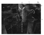
도 5는 본 발명의 일 실시예에 따른 영상 정합 장치에서 대상체를 가상 영상에 표시하는 방법을 설명하기 위한 도면이고, 도 6은 본 발명의 일 실시예에 따른 영상 정합 장치에서 가상 영상을 생성할 방향을 결정하는 방법을 설명하기 위한 도면이고, 도 7은 본 발명의 일 실시예에 따른 영상 정합 장치에서 포인트 클라우드가 위치하는 3차원 관심 공간 상에 생성된 LSP를 예시한 도면이며, 도 8은 본 발명의 일 실시예에 따른 영상 정합 장치가 생성한 가상 영상을 예시한 도면이다.5 is a diagram for explaining a method of displaying an object in a virtual image in an image matching device according to an embodiment of the present invention, and FIG. 6 is a diagram for generating a virtual image in the image matching device according to an embodiment of the present invention. A diagram for explaining a method of determining a direction, and FIG. 7 is a diagram illustrating an LSP generated on a 3D ROI in which a point cloud is located in an image matching apparatus according to an embodiment of the present invention, and FIG. 8 is A diagram illustrating a virtual image generated by an image matching device according to an embodiment of the present invention.
영상 정합 장치(130)의 가상 영상 생성부(131)는 포인트 클라우드로부터 가상 영상을 생성할 수 있다. 도 5를 참조하면, 가상 영상 생성부(131)는 3차원 관심 공간 Mp 상에서 초점 f로부터 연장되는 방향에 위치하는 포인트 클라우드의 3차원 좌표를 가상 영상 Iv내의 2차원 좌표로 변환할 수 있다. 구체적으로, 가상 영상 Iv가 W1×W2의 크기를 갖도록 설정되고, 초점 f로부터 초점 거리 fl만큼 이격된 거리에 가상 영상 Iv가 배치될 때, 가상 영상 생성부(131)는 초점 f로부터 포인트 클라우드의 점 r(x,y,z)로 연장되는 직선이 가상 영상 Iv를 지나는 픽셀 p(u,v)를 포인트 클라우드의 점 r(x,y,z)의 가상 영상 내 픽셀 좌표로 결정할 수 있다.The
만약, 초점 f가 중심에 위치하는 정육면체의 각 면에 대응하는 6 개의 가상 영상 Iv을 생성하고자 하는 경우, 즉, 초점 f에 대한 정육면체의 Laser Scan Picture(LSP)를 생성하고자 하는 경우, 가상 영상 Iv의 세로 폭 W1과 가로 폭 W1은 W로 같고, 초점 거리 fl은 W/2로 결정될 필요가 있다. 이 경우, 가상 영상 내 픽셀 p의 좌표(u,v)는 초점 거리 fl 또는 W/2와 z값의 비율에 따라 결정될 수 있다. If you want to create 6 virtual images I v corresponding to each side of the cube where the focal point f is located at the center, that is, when you want to generate the laser scan picture (LSP) of the cube for the focal point f, a virtual image The vertical width W 1 and the horizontal width W 1 of I v are equal to W, and the focal length f l needs to be determined as W/2. In this case, the coordinates (u, v) of the pixel p in the virtual image may be determined according to the focal length f 1 or the ratio of the W/2 and z values.
즉, 가상 영상 내 픽셀 p의 좌표(u,v)는 가상 영상 Iv의 크기 W1×W2와 초점 거리 fl에 의해 결정될 수 있다. 이렇게 생성된 가상 영상 Iv는 추후 촬영 영상 Ir 과 정합을 수행할 수 있는데, 정합에 이용되는 촬영 영상 Ir의 크기 및/또는 촬영 영상 Ir에 대한 초점 거리 등의 값이 상이하다면, 정합의 정확도가 낮아질 수 있다.That is, the coordinates (u,v) of the pixel p in the virtual image may be determined by the size W 1 ×W 2 of the virtual image I v and the focal length f 1. The generated virtual image I v is if later captured image I r, and may perform the matching, different from this value, such as the focal length of the shooting image I r size and / or the captured image I r of which is used for matching, the matching The accuracy of may be lowered.
따라서, 본 발명의 일 실시예에 따른 가상 영상 생성부(131)는 촬영 영상 Ir을 획득하는 카메라(120)의 내부 파라미터를 이용하여 가상 영상 Iv을 생성함으로써, 가상 영상 Iv 및 촬영 영상 Ir 간 정합의 정확도를 높일 수 있다.Accordingly, the virtual
구체적으로, 가상 영상 생성부(131)는 수학식 1에 따라 가상 영상 내 픽셀 p의 좌표(u,v)를 획득할 수 있다.Specifically, the

여기서, zc는 스케일 팩터(Scale Factor)를 의미하고, [R T]는 카메라(120)의 외부 파라미터로서, R은 회전 행렬을 의미하고, T는 이동 행렬을 의미할 수 있다. 또한, K는 카메라(120) 내부 파라미터를 의미할 수 있으며, 수학식 2에 따라 정의될 수 있다.Here, z c denotes a scale factor, [RT] denotes an external parameter of the

여기서, αx는 초점 거리 fl에 x축에 대한 스케일 팩터 mx를 곱한 값을 의미하고, αy는 초점 거리 fl에 y축에 대한 스케일 팩터 my를 곱한 값을 의미하고, γ은 x축 및 y축 사이의 스큐 상수(Skew Coefficient)를 의미하고, u0 및 v0는 주점(Principal Point)를 의미할 수 있다. Here, α x denotes a value obtained by multiplying the focal length f l by the scale factor m x for the x-axis, α y denotes the value obtained by multiplying the focal length f l by the scale factor m y for the y-axis, and γ It means a skew coefficient between the x-axis and the y-axis, and u 0 and v 0 may mean a principal point.
이 때, 가상 영상 생성부(131)는 상술한 초점 거리 fl, 스큐 상수 γ, 주점의 좌표 (u0 및 v0) 등을 촬영 영상 Ir을 획득한 카메라(120)의 내부 파라미터 값으로 결정할 수 있고, 스케일 팩터 mx, my 역시 카메라(120) 내부 파라미터 중 이미지 센서 포멧 값에 따라 결정할 수 있다.In this case, the virtual
이 밖에도 가상 영상 생성부(131)는 카메라(120) 내부 파라미터 중 하나인 해상도 값을 이용함으로써, 촬영 영상 Ir과 가상 영상 Iv의 해상도를 일치시킬 수 있다. 뿐만 아니라, 상술한 수학식 2에는 선형적 내부 파라미터만을 언급하고 있으나, 가상 영상 생성부(131)는 렌즈 왜곡 파라미터(Lens Distortion Parameter)와 같은 비선형적 내부 파라미터도 가상 영상 Iv 생성 시 동일하게 적용할 수 있다.In addition, the
상술한 카메라(120)의 내부 파라미터는 외부 장치 또는 사용자에 의해 3D 모델링 장치(100)에 직접 입력되거나, 3D 모델링 장치(100)가 연산을 통해 획득할 수 있다. 연산을 통해 카메라(120)의 내부 파라미터를 획득하는 경우, 3D 모델링 장치(100)는 카메라에 의해 체스 보드(Chess Board)와 같은 격자 패턴에 대한 테스트 영상을 획득하고, 이를 기초로 카메라 캘리브레이션을 수행함으로써, 카메라(120)의 내부 파라미터를 획득할 수 있다. 이 밖에도, 3D 모델링 장치(100)는 공지된 다양한 방법에 따라 카메라(120)의 내부 파라미터를 획득할 수 있다.The above-described internal parameters of the
가상 영상 생성부(131)는 초점 f로부터 결정되는 복수의 방향에 대한 복수의 가상 영상 Iv을 생성할 수 있다. 구체적으로, 가상 영상 생성부(131)는 초점 f를 교점으로 하는 상호 수직인 3개의 축을 따르는 6개의 방향에 대한 6개의 가상 영상 Iv을 생성할 수 있다. 만약, 3개의 축이 초점 f를 원점으로 하는 x축, y축, z축으로 결정되는 경우, 가상 영상 생성부(131)는 x축 방향에 수직인 제 1 가상 영상, -x축 방향에 수직인 제 2 가상 영상, y축 방향에 수직인 제 3 가상 영상, -y축 방향에 수직인 제 4 가상 영상, z축 방향에 수직인 제 5 가상 영상, 및 -z축 방향에 수직인 제 6 가상 영상을 획득할 수 있다. The
이와 같이 초점 f를 중심으로 생성되는 가상 영상 Iv을 평면으로 하는 다면체를 LSP라 하며, 상술한 예에서는 가상 영상 생성부(131)가 초점 f에 대한 정육면체의 LSP를 생성하였다고 볼 수 있다. In this way, a polyhedron having a virtual image I v generated around a focal point f as a plane is referred to as an LSP, and in the above-described example, the virtual
나아가, 가상 영상 생성부(131)는 초점 f로부터 7개 이상의 방향에 대한 가상 영상 Iv을 생성할 수 있다. 이를 위해, 가상 영상 생성부(131)는 초점 f를 교점으로 하는 상호 수직인 3개의 축 중 적어도 하나를 기준으로 회전된 복수의 방향에 대하여 복수의 가상 영상 Iv을 생성할 수 있다.Furthermore, the
도 6을 참조하면, 3차원 관심 공간 Mp상의 초점 f를 교점으로 하는 상호 수직 관계의 x축, y축, 및 z축이 결정되면, 가상 영상 생성부(131)는 적어도 한 축을 기준으로 회전된 복수의 방향에 대한 복수의 가상 영상 Iv을 생성할 수 있다. 예를 들어, 가상 영상 생성부(131)는 z축을 기준으로 회전, 즉 Pan 회전 함에 따른 복수의 방향에 대한 복수의 가상 영상 Iv을 획득할 수 있다. 또한, 가상 영상 생성부(131)는 y축을 기준으로 회전, 즉 Roll 회전 함에 따른 복수의 방향에 대한 복수의 가상 영상 Iv을 획득할 수 있다. 나아가, 가상 영상 생성부(131)는 x축을 기준으로 회전, 즉 Tilt 회전 함에 따른 복수의 방향에 대한 복수의 가상 영상 Iv을 획득할 수도 있다.Referring to FIG. 6, when the x-axis, y-axis, and z-axis of a mutually perpendicular relationship with a focal point f on a three-dimensional space of interest M p as an intersection point are determined, the virtual image generator 131 rotates based on at least one axis. It is possible to generate a plurality of virtual images I v for a plurality of directions. For example, the virtual image generator 131 may obtain a plurality of virtual images I v for a plurality of directions according to rotation based on the z-axis, that is, pan rotation. In addition, the virtual image generator 131 may obtain a plurality of virtual images I v for a plurality of directions according to rotation based on the y-axis, that is, roll rotation. Furthermore, the
도 7에서는 3차원 관심 공간 Mp 상의 초점 f를 기준으로 pan 회전에 따른 서로 다른 5개의 방향과 z축, -z축 방향 각각에 대한 7개의 가상 영상 Iv으로 구현되는 오각기둥 형상의 LSP(L)를 예시한다. 이와 같이 특정 초점 f에 대하여 7개 이상의 가상 영상 Iv을 생성함으로써, 3D 모델링 시 관심 공간에 대한 보다 많은 정보를 제공할 수 있다.In FIG. 7, the three-dimensional space of interest M p The LSP(L) of a pentagonal column shape implemented with 5 different directions according to the pan rotation based on the focal point f of the image and 7 virtual images I v for each of the z-axis and -z-axis directions is illustrated. As described above, by generating 7 or more virtual images I v for a specific focal point f, more information on a space of interest can be provided during 3D modeling.
도 8에서는 상술한 방법에 따라 초점 f를 기준으로 생성된 복수의 가상 영상 Iv를 예시한다. 도 8을 참조하면, 복수의 가상 영상 Iv 은 초점 f로부터 다양한 방향에 대한 시각적 정보를 포함함을 확인할 수 있다. 8 illustrates a plurality of virtual images I v generated based on a focus f according to the above-described method. Referring to FIG. 8, it can be seen that the plurality of virtual images I v include visual information for various directions from the focus f.
또한, 가상 영상 생성부(131)는 포인트 클라우드를 획득한 라이다(112)의 위치를 기초로 초점 f를 결정할 수 있다. 구체적으로, 가상 영상 생성부(131)는 3D 스캐너(110) 상의 라이다(112)의 회전 축에 대한 중심점을 초점 f로 결정하고, 이에 대한 복수의 가상 영상 Iv를 생성할 수 있다.Also, the
뿐만 아니라, 가상 영상 생성부(131)는 3차원 관심 공간 상의 임의의 위치를 초점 f로 결정할 수도 있다. 예를 들어, 가상 영상 생성부(131)는 사용자로부터 입력된 3차원 관심 공간 상의 관심 위치를 초점 f로 결정하고, 이에 대한 복수의 가상 영상 Iv를 생성할 수 있다. 이 때, 관심 위치는 사용자의 입력에 따라 관심 공간 내 서로 다른 좌표로서 결정될 수 있다.In addition, the
특히, 가상 영상 생성부(131)는 사용자로부터 입력된 복수의 관심 위치를 초점 f로 하여, 각각의 초점 f에 대한 복수의 가상 영상 I v 를 생성할 수 있다. In particular, the virtual image generator 131 may generate a plurality of virtual images I v for each focus f by using a plurality of points of interest input from the user as the focus f.
이하에서는 도 9 내지 11을 참조하여 복수의 초점 각각에 대한 복수의 가상 영상을 생성하는 방법을 설명한다.Hereinafter, a method of generating a plurality of virtual images for each of a plurality of focal points will be described with reference to FIGS. 9 to 11.
도 9는 본 발명의 일 실시예에 따른 복수의 초점 각각에 대한 복수의 가상 영상 생성 방법의 흐름도이고, 도 10은 본 발명의 다른 실시예에 따른 영상 정합 장치에서 포인트 클라우드가 위치하는 3차원 관심 공간 상에 생성된 복수의 LSP를 예시한 도면이고, 도 11은 본 발명의 다른 실시예에 따른 영상 정합 장치가 생성한 복수의 가상 영상을 예시한 도면이다.9 is a flowchart of a method for generating a plurality of virtual images for each of a plurality of focal points according to an embodiment of the present invention, and FIG. 10 is a three-dimensional interest in which a point cloud is located in an image matching device according to another embodiment of the present invention. A diagram illustrating a plurality of LSPs generated in a space, and FIG. 11 is a diagram illustrating a plurality of virtual images generated by an image matching apparatus according to another embodiment of the present invention.
먼저, 가상 영상 생성부(131)는 포인트 클라우드를 이용하여 관심 공간에 대한 3D 메쉬(3D Mesh)를 생성할 수 있다(S121). 이하에서는, 후술할 영상 처리부(140)에 의해 생성되는 3D 메쉬와 구분하기 위해, 가상 영상 생성부(131)에 의해 생성되는 3D 메쉬를 제 1 3D 메쉬라 한다.First, the
가상 영상 생성부(131)는 포인트 클라우드를 본(Bone)과 정점(Vertex)로 하여, 복수의 정점이 본에 의해 리깅되는 제 1 3D 메쉬를 생성할 수 있다. 이렇게 생성되는 제 1 3D 메쉬는 적어도 세 개의 정점이 이루는 복수의 폴리곤(Polygon)으로 구성될 수 있다. 그 결과, 제 1 3D 메쉬는 무수히 많은 정점과 이들이 이루는 폴리곤을 포함함을 확인할 수 있다.The
만약, 포인트 클라우드가 복수의 라이다(112)에 의해 획득된 경우, 가상 영상 생성부(131)는 제 1 3D 메쉬를 생성하기에 앞서, 서로 다른 라이다(112)에 의해 획득된 포인트 클라우드 간의 정렬을 선행할 수 있다. 구체적으로, 가상 영상 생성부(131)는 서로 다른 라이다(112)에 의해 획득된 포인트 클라우드 중 동일한 공간 정보를 포함하는 포인트 클라우드를 상호 매칭함으로써, 서로 다른 라이다(112) 간의 위치 관계를 획득할 수 있다. If the point clouds are acquired by the plurality of
일 실시예에 따른 가상 영상 생성부(131)는 어느 하나의 라이다로부터 획득된 포인트 클라우드 중 어느 하나를 기준으로 이에 대응되는 다른 하나의 라이다로부터 획득된 포인트 클라우드를 정합하기 위한 이동 정보 및 회전 정보를 획득할 수 있다. 여기서, 이동 정보란 정합을 위한 이동 행렬(Translation Matrix)을 포함하고, 회전 정보는 회전 행렬(Rotation Matrix)를 포함할 수 있다.The virtual
제 1 3D 메쉬가 생성되면, 가상 영상 생성부(131)는 카메라의 내부 파라미터를 이용하여 제 1 3D 메쉬로부터 복수의 관심 위치 각각에서의 복수의 가상 영상을 생성할 수 있다(S122). 여기서, 카메라의 내부 파라미터를 이용하여 가상 영상을 생성하는 방법은 도 5 내지 8을 통해 설명한 바와 같으므로, 이하에서는 제 1 3D 메쉬로부터 가상 영상을 생성하는 방법을 중점적으로 설명한다.When the first 3D mesh is generated, the
상술한 바와 같이, 가상 영상 생성부(131)는 사용자로부터 입력된 복수의 관심 위치 각각을 가상 영상 생성을 위한 초점 f로 결정할 수 있다. 그 다음, 가상 영상 생성부(131)는 결정된 각각의 초점 f로부터 제 1 3D 메쉬에 대한 거리를 기초로 복수의 가상 영상을 생성할 수 있다.As described above, the
일 실시예에 따른 가상 영상 생성부(131)는 오클루전 테스트(Occlusion Test)를 수행함으로써 각각의 초점 f에서의 가상 영상을 생성할 수 있다. 여기서, 오클루전 테스트란 미리 정해진 위치에 인접한 물체(Occlusion)에 가려진 후방 물체를 배제하는 방법을 의미할 수 있다. 즉, 가상 영상 생성부(131)는 각각의 초점 f에서 미리 정해진 방향에 대하여 가상의 광선을 조사하였을 때, 해당 광선과 우선하여 만나는 제 1 3D 메쉬 정보만을 선택하여 가상 영상을 생성할 수 있다. The
도 10을 참조하면, 가상 영상 생성부(131)는 사용자에 의해 입력된 복수의 관심 위치 각각을 초점 f 1 내지 f 6 으로 결정하고, 각각의 초점 f 1 내지 f 6 에서의 LSP L 1 내지 L 6 을 생성할 수 있다. 또한, 도 11을 참조하면, 이렇게 생성된 LSP L 1 내지 L 6 각각은 복수의 가상 영상 Iv 1 내지 Iv 6 을 포함할 수 있다.10, the virtual
이처럼, 본 발명의 일 실시예에 따른 가상 영상 생성부(131)는 포인트 클라우드를 획득한 라이다(112)의 위치뿐만 아니라 사용자의 입력 등에 기초하여 복수의 초점 f를 결정할 수 있으므로, 보다 다양한 위치에서의 복수의 가상 영상 Iv을 획득할 수 있다. 이를 통해, 라이다와 카메라 간의 정합 정확도를 높일 수 있다.As such, the virtual
다시 도 2를 참조하면, 영상 정합 장치(130)는 복수의 촬영 영상 Ir과 복수의 가상 영상 Iv을 정합할 수 있다(S130). 이하에서는 도 12를 참조하여 복수의 촬영 영상 Ir과 복수의 가상 영상 Iv을 정합하는 방법을 설명한다.Referring back to FIG. 2, the image matching device 130 may match a plurality of captured images I r and a plurality of virtual images I v (S130 ). Hereinafter, a method of matching a plurality of captured images I r and a plurality of virtual images I v will be described with reference to FIG. 12.
도 12는 본 발명의 일 실시예에 따른 정합부에서 촬영 영상과 가상 영상을 정합하는 방법을 설명하기 위한 도면이다.12 is a diagram illustrating a method of matching a captured image and a virtual image in a matching unit according to an embodiment of the present invention.
복수의 촬영 영상 Ir 및 복수의 가상 영상 Iv의 정합을 위해, 영상 정합 장치(130)의 정합부(132)는 복수의 촬영 영상 Ir 및 복수의 가상 영상 Iv 각각으로부터 특징점을 추출할 수 있다. 구체적으로, 정합부(132)는 복수의 촬영 영상 Ir 및 복수의 가상 영상 Iv 각각에서 코너(Corner), 엣지(Edge), 경사(Gradient) 등을 기초로 특징점을 추출할 수 있다. In order to match the plurality of captured images I r and the plurality of virtual images I v , the
그 다음, 정합부(132)는 복수의 촬영 영상 Ir로부터 추출된 특징점 fr과 복수의 가상 영상 Iv으로부터 추출된 특징점 fv를 매칭하여, 복수의 촬영 영상 Ir과 복수의 가상 영상 Iv를 정합할 수 있다. 일 실시예에 따른 정합부(132)는 각각의 특징점의 컬러 정보를 기초로 특징점 fr과 특징점 fv를 매칭할 수 있다. 도 9를 참조하면, 촬영 영상 Ir로부터 추출된 복수의 특징점 fr과 가상 영상 Iv으로부터 추출된 복수의 특징점 fv이 상호 매칭됨을 확인할 수 있다.Then, the
나아가, 정합부(132)는 정합된 촬영 영상 Ir과 가상 영상 Iv 간의 위치 관계를 획득할 수 있다. 구체적으로, 정합부(132)는 촬영 영상 Ir과 가상 영상 Iv 중 어느 하나를 기준으로 다른 하나를 정합하기 위한 이동 정보 및 회전 정보를 획득할 수 있다. 여기서, 이동 정보는 정합을 위한 이동 행렬(Translation Matrix)을 포함하고, 회전 정보는 회전 행렬(Rotation Matrix)를 포함할 수 있다.Furthermore, the
다시 도 1을 참조하면, 영상 처리부(140)는 정합 결과를 기초로 관심 공간에 대한 3D 모델링을 수행할 수 있다. 이하에서는 도 13 및 14를 참조하여 3D 모델링 방법을 설명한다.Referring back to FIG. 1, the
도 13은 본 발명의 일 실시예에 따른 영상 처리부가 생성한 3D 메쉬를 예시한 도면이고, 도 14는 본 발명의 일 실시예에 따른 영상 처리부가 생성한 3D 모델을 예시한 도면이다.13 is a diagram illustrating a 3D mesh generated by an image processing unit according to an embodiment of the present invention, and FIG. 14 is a diagram illustrating a 3D model generated by an image processing unit according to an embodiment of the present invention.
도 13을 참조하면, 영상 처리부(140)는 특징점을 기초로 3D 메쉬(3D Mesh, Ms)를 생성할 수 있다. 이하에서는, 상술한 가상 영상 생성부(131)에 의해 생성되는 제 1 3D 메쉬와 구분하기 위해, 가상 영상 생성부(131)에 의해 생성되는 3D 메쉬를 제 2 3D 메쉬라 한다.Referring to FIG. 13, the
구체적으로, 영상 처리부(140)는 추출된 특징점을 본(Bone)과 정점(Vertex)로 하여, 복수의 정점이 본에 의해 리깅되는 제 2 3D 메쉬 MS를 생성할 수 있다. Specifically, the
이렇게 생성되는 제 2 3D 메쉬 MS는 적어도 세 개의 정점이 이루는 복수의 폴리곤(Polygon)으로 구성될 수 있다. 도 13을 참조하면, 제 2 3D 메쉬 MS는 무수히 많은 정점과 이들이 이루는 폴리곤을 포함함을 확인할 수 있다.The second 3D mesh M S generated in this way may be composed of a plurality of polygons comprising at least three vertices. Referring to FIG. 13, it can be seen that the second 3D mesh M S includes a myriad of vertices and polygons formed by them.
이렇게 제 2 3D 메쉬 MS를 생성한 후, 영상 처리부(140)는 제 2 3D 메쉬 MS에 텍스쳐링(Texturing)을 수행하여 3D 모델 MO를 생성할 수 있다. 구체적으로, 영상 처리부(140)는 제 2 3D 메쉬 MS에 대하여 각각의 폴리곤을 형성하는 각각의 정점의 컬러 정보를 기초로 해당 폴리곤에 컬러를 적용함으로써 텍스쳐링을 수행할 수 있다. 도 14를 참조하면, 제 2 3D 메쉬 MS를 텍스쳐링 하여 얻어진 3D 모델 MO는 실제 관심 공간과 유사한 형태의 가상 관심 공간을 형성함을 확인할 수 있다.After generating the second 3D mesh M S in this way, the
도 1에서는 영상 정합 장치(130)가 3D 모델링 장치(100)의 일 구성으로 마련되는 경우를 예시하였으나, 영상 정합 장치(130)가 3D 스캐너(110), 카메라(120), 및 영상 처리부(140) 중 적어도 하나를 더 포함하도록 마련될 수 있다. 특히, 영상 정합 장치(130)가 3D 스캐너(110), 카메라(120), 및 영상 처리부(140) 모두를 포함하는 경우, 영상 정합 장치(130)는 3D 모델링 장치(100)로서 구현된다고 볼 수 있다.1 illustrates a case in which the image matching device 130 is provided as a component of the
상술한 영상 정합 장치(130) 및 영상 처리부(140)는 마이크로프로세서(Microprocessor)를 포함하는 연산 장치로 구현될 수 있고, 예를 들어 중앙 처리 장치(Central Processing Unit, CPU) 및 그래픽 처리 장치(Graphic Processing Unit, GPU) 중 적어도 하나로 구현될 수 있다. 이와는 달리, 영상 정합 장치(130) 및 영상 처리부(140)가 하나의 SOC(System On Chip)으로 구현되는 것도 가능할 수 있다.The image matching device 130 and the
상술한 실시예에 따른 영상 정합 장치 및 방법은, 사용자의 입력 등에 기초하여 복수의 초점 f를 결정함으로써 보다 다양한 위치에서의 복수의 가상 영상을 획득할 수 있다. 이를 통해, 라이다와 카메라 간의 정합 정확도를 높일 수 있다.The image matching apparatus and method according to the above-described embodiment may obtain a plurality of virtual images at more various locations by determining a plurality of focal points f based on a user's input or the like. Through this, it is possible to increase the accuracy of matching between the lidar and the camera.
또한, 상술한 실시예에 따른 영상 정합 장치 및 방법은 카메라의 내부 파라미터를 기초로 생성된 가상 영상을 카메라에 의해 획득된 촬영 영상과 정합하므로, 영상 정합의 정확도를 높일 수 있다. 또한, 특정 위치에서 복수의 방향에 대한 가상 영상을 생성하고, 생성된 가상 영상과 촬영 영상의 정합 결과를 3D 모델링의 수행 시 제공하므로, 최종 생성되는 3D 모델의 실감도가 높아질 수 있다.In addition, since the image matching apparatus and method according to the above-described embodiment matches the virtual image generated based on the internal parameters of the camera with the captured image acquired by the camera, it is possible to increase the accuracy of image matching. In addition, since virtual images for a plurality of directions are generated at a specific location, and a result of matching the generated virtual image and the captured image is provided when 3D modeling is performed, the sense of reality of the finally generated 3D model may be increased.
한편, 상술한 실시예에 따른 영상 정합 방법에 포함된 각각의 단계는, 이러한 단계를 수행하도록 프로그램된 컴퓨터 프로그램 또는 컴퓨터 프로그램을 기록하는 컴퓨터 판독가능한 기록매체에서 구현될 수 있다.Meanwhile, each step included in the image matching method according to the above-described embodiment may be implemented in a computer program programmed to perform such a step or a computer-readable recording medium recording the computer program.
이상의 설명은 본 발명의 기술 사상을 예시적으로 설명한 것에 불과한 것으로서, 본 발명이 속하는 기술 분야에서 통상의 지식을 가진 자라면 본 발명의 본질적인 품질에서 벗어나지 않는 범위에서 다양한 수정 및 변형이 가능할 것이다. 따라서, 본 발명에 개시된 실시예들은 본 발명의 기술 사상을 한정하기 위한 것이 아니라 설명하기 위한 것이고, 이러한 실시예에 의하여 본 발명의 기술 사상의 범위가 한정되는 것은 아니다. 본 발명의 보호 범위는 아래의 청구범위에 의하여 해석되어야 하며, 그와 균등한 범위 내에 있는 모든 기술사상은 본 발명의 권리범위에 포함되는 것으로 해석되어야 할 것이다.The above description is merely illustrative of the technical idea of the present invention, and those of ordinary skill in the art to which the present invention pertains will be able to make various modifications and variations without departing from the essential quality of the present invention. Accordingly, the embodiments disclosed in the present invention are not intended to limit the technical idea of the present invention, but to explain the technical idea, and the scope of the technical idea of the present invention is not limited by these embodiments. The scope of protection of the present invention should be interpreted by the following claims, and all technical ideas within the scope equivalent thereto should be construed as being included in the scope of the present invention.
일 실시예에 따르면, 상술한 영상 정합 장치 및 방법은 댁내 또는 산업 현장 등 다양한 분야에서 이용될 수 있으므로 산업상 이용 가능성이 있다.According to an embodiment, since the above-described image matching apparatus and method can be used in various fields such as indoors or industrial sites, there is a possibility of industrial use.
100: 3D 모델링 장치
110: 3D 스캐너
111: 스캔 카메라
112: 라이다
120: 카메라
130: 영상 정합 장치
131: 가상 영상 생성부
132: 정합부
140: 영상 처리부100: 3D modeling device
110: 3D scanner
111: scan camera
112: Lida
120: camera
130: video matching device
131: virtual image generation unit
132: matching portion
140: image processing unit
Claims (10)
라이다에 의해 획득된 관심 공간의 포인트 클라우드를 이용하여 상기 관심 공간에 대한 3D 메쉬(3D Mesh)를 생성하는 단계;
카메라의 내부 파라미터(Intrinsic Parameter)를 이용하여 상기 생성된 3D 메쉬로부터 복수의 관심 위치 각각에서의 복수의 가상 영상을 생성하는 단계; 및
상기 카메라에 의해 획득된 상기 관심 공간에 대한 복수의 촬영 영상과 상기 복수의 가상 영상을 정합(Registration)하는 단계를 포함하는
영상 정합 방법.
In the image matching method performed in the image matching device,
Generating a 3D mesh for the space of interest by using the point cloud of the space of interest acquired by the lidar;
Generating a plurality of virtual images at each of a plurality of points of interest from the generated 3D mesh using an intrinsic parameter of a camera; And
Comprising the step of registering a plurality of photographed images and the plurality of virtual images of the space of interest acquired by the camera
Image registration method.
상기 복수의 관심 위치는,
사용자의 입력에 따라 상기 관심 공간 내 서로 다른 좌표로서 결정되는
영상 정합 방법.
The method of claim 1,
The plurality of positions of interest,
Determined as different coordinates in the space of interest according to the user's input
Image registration method.
상기 복수의 가상 영상을 생성하는 단계는,
상기 복수의 관심 위치 각각을 초점으로 결정하는 단계;
상기 3D 메쉬에 대하여 상기 결정된 초점으로부터의 거리를 기초로 상기 복수의 가상 영상을 생성하는 단계를 포함하는
영상 정합 방법.
The method of claim 1,
Generating the plurality of virtual images,
Determining each of the plurality of interest positions as a focus;
Generating the plurality of virtual images based on the determined distance from the focal point of the 3D mesh
Image registration method.
상기 복수의 가상 영상을 생성하는 단계는,
상기 결정된 초점을 교점으로 하는 상호 수직인 3개의 축 중 적어도 하나를 기준으로 회전된 복수의 방향에 대하여 상기 복수의 가상 영상을 생성하는
영상 정합 방법.
The method of claim 3,
Generating the plurality of virtual images,
Generating the plurality of virtual images in a plurality of directions rotated based on at least one of three mutually perpendicular axes having the determined focus as an intersection point
Image registration method.
상기 카메라의 내부 파라미터는,
상기 카메라의 초점 거리(Focal Length), 이미지 센서 포맷(Image Sensor Format), 스큐(Skew), 주점(Principal Point), 렌즈 왜곡 파라미터(Lens Distortion Parameter), 해상도(Resolution) 중 적어도 하나를 포함하는
영상 정합 방법.
The method of claim 1,
The camera's internal parameters are:
Including at least one of a focal length of the camera, an image sensor format, a skew, a principal point, a lens distortion parameter, and a resolution.
Image registration method.
상기 복수의 촬영 영상과 상기 복수의 가상 영상을 정합하는 단계는,
상기 복수의 촬영 영상 및 상기 복수의 가상 영상 각각으로부터 특징점을 추출하는 단계; 및
상기 복수의 촬영 영상으로부터 추출된 특징점과 상기 복수의 가상 영상으로부터 추출된 특징점을 매칭하여, 상기 복수의 촬영 영상과 상기 복수의 가상 영상을 정합하는 단계를 포함하는
영상 정합 방법.
The method of claim 1,
The step of matching the plurality of photographed images and the plurality of virtual images,
Extracting feature points from each of the plurality of captured images and the plurality of virtual images; And
And matching the feature points extracted from the plurality of captured images with the feature points extracted from the plurality of virtual images, and matching the plurality of captured images with the plurality of virtual images
Image registration method.
상기 정합된 촬영 영상과 상기 정합된 가상 영상 간의 위치 관계를 획득하는 단계를 더 포함하고,
상기 촬영 영상과 상기 가상 영상 간의 위치 관계는,
상기 촬영 영상 및 상기 가상 영상 중 어느 하나를 기준으로 다른 하나를 정합하기 위한 이동 정보 및 회전 정보를 포함하는
영상 정합 방법.
The method of claim 1,
Further comprising the step of obtaining a positional relationship between the matched captured image and the matched virtual image,
The positional relationship between the captured image and the virtual image,
Including movement information and rotation information for matching the other one based on any one of the captured image and the virtual image
Image registration method.
상기 카메라에 의해 획득된 상기 공간에 대한 복수의 촬영 영상과 상기 복수의 가상 영상을 정합(Registration)하는 정합부를 포함하는
영상 정합 장치.
A 3D mesh for the space of interest is generated by using the point cloud of the space of interest acquired by the lidar, and a plurality of positions of interest from the generated 3D mesh using an intrinsic parameter of the camera A virtual image generator for generating a plurality of virtual images in each; And
Comprising a registration unit for registering a plurality of photographed images of the space acquired by the camera and the plurality of virtual images
Video matching device.
A program stored in a computer-readable recording medium that performs each step according to the method according to any one of claims 1 to 7
A computer-readable recording medium on which a program including instructions for performing each step according to the method according to any one of claims 1 to 7 is recorded.
Priority Applications (1)
| Application Number | Priority Date | Filing Date | Title |
|---|---|---|---|
| KR1020190134872A KR20210050365A (en) | 2019-10-28 | 2019-10-28 | Apparatus and method for registering images |
Applications Claiming Priority (1)
| Application Number | Priority Date | Filing Date | Title |
|---|---|---|---|
| KR1020190134872A KR20210050365A (en) | 2019-10-28 | 2019-10-28 | Apparatus and method for registering images |
Publications (1)
| Publication Number | Publication Date |
|---|---|
| KR20210050365A true KR20210050365A (en) | 2021-05-07 |
Family
ID=75916774
Family Applications (1)
| Application Number | Title | Priority Date | Filing Date |
|---|---|---|---|
| KR1020190134872A KR20210050365A (en) | 2019-10-28 | 2019-10-28 | Apparatus and method for registering images |
Country Status (1)
| Country | Link |
|---|---|
| KR (1) | KR20210050365A (en) |
Cited By (2)
| Publication number | Priority date | Publication date | Assignee | Title |
|---|---|---|---|---|
| CN117078912A (en) * | 2023-07-10 | 2023-11-17 | 中国地质大学(武汉) | Laser point cloud and image alignment method and device based on deep learning |
| CN117152330A (en) * | 2023-07-10 | 2023-12-01 | 中国地质大学(武汉) | Point cloud 3D model mapping method and device based on deep learning |
Citations (1)
| Publication number | Priority date | Publication date | Assignee | Title |
|---|---|---|---|---|
| KR20150129260A (en) | 2014-05-09 | 2015-11-19 | 주식회사 아이너지 | Service System and Method for Object Virtual Reality Contents |
-
2019
- 2019-10-28 KR KR1020190134872A patent/KR20210050365A/en unknown
Patent Citations (1)
| Publication number | Priority date | Publication date | Assignee | Title |
|---|---|---|---|---|
| KR20150129260A (en) | 2014-05-09 | 2015-11-19 | 주식회사 아이너지 | Service System and Method for Object Virtual Reality Contents |
Cited By (3)
| Publication number | Priority date | Publication date | Assignee | Title |
|---|---|---|---|---|
| CN117078912A (en) * | 2023-07-10 | 2023-11-17 | 中国地质大学(武汉) | Laser point cloud and image alignment method and device based on deep learning |
| CN117152330A (en) * | 2023-07-10 | 2023-12-01 | 中国地质大学(武汉) | Point cloud 3D model mapping method and device based on deep learning |
| CN117152330B (en) * | 2023-07-10 | 2024-05-28 | 中国地质大学(武汉) | Point cloud 3D model mapping method and device based on deep learning |
Similar Documents
| Publication | Publication Date | Title |
|---|---|---|
| KR102160196B1 (en) | Apparatus and method for 3d modeling | |
| KR102109814B1 (en) | Apparatus and method for registering images | |
| US9972120B2 (en) | Systems and methods for geometrically mapping two-dimensional images to three-dimensional surfaces | |
| CN107025663A (en) | It is used for clutter points-scoring system and method that 3D point cloud is matched in vision system | |
| US11490062B2 (en) | Information processing apparatus, information processing method, and storage medium | |
| CN103562934B (en) | Face location detection | |
| JP6541920B1 (en) | INFORMATION PROCESSING APPARATUS, PROGRAM, AND INFORMATION PROCESSING METHOD | |
| JP7479729B2 (en) | Three-dimensional representation method and device | |
| JP3855053B2 (en) | Image processing apparatus, image processing method, and image processing program | |
| TW201707437A (en) | Image processing device and image processing method | |
| KR20210050365A (en) | Apparatus and method for registering images | |
| JP2004220312A (en) | Multi-viewpoint camera system | |
| JP2004280776A (en) | Method for determining shape of object in image | |
| CN113945167B (en) | Workpiece data acquisition method and device | |
| KR101817756B1 (en) | PTM making system based on 3D model with interactive viewpoint control and method using the same | |
| JPH05135155A (en) | Three-dimensional model constitution device using successive silhouette image | |
| KR20210050366A (en) | Apparatus and method for determining camera pose | |
| CN107534730B (en) | Image processing apparatus and image processing method | |
| JP2013231607A (en) | Calibration tool display device, calibration tool display method, calibration device, calibration method, calibration system and program | |
| Maimone et al. | A taxonomy for stereo computer vision experiments | |
| CN107534729B (en) | Image processing apparatus, image processing method, and program | |
| Sosa et al. | 3D surface reconstruction of entomological specimens from uniform multi-view image datasets | |
| JP6984870B2 (en) | 3D shape measuring device, 3D shape measuring method, and 3D shape measuring program | |
| Ahmad Yusri et al. | Preservation of cultural heritage: a comparison study of 3D modelling between laser scanning, depth image, and photogrammetry methods | |
| JP2004170277A (en) | 3-dimensional measurement method, 3-dimensional measurement system, image processing apparatus, and computer program |