KR102621527B1 - Rotor sleeve for motor and motor for vehicle including the same - Google Patents
Rotor sleeve for motor and motor for vehicle including the same Download PDFInfo
- Publication number
- KR102621527B1 KR102621527B1 KR1020180139264A KR20180139264A KR102621527B1 KR 102621527 B1 KR102621527 B1 KR 102621527B1 KR 1020180139264 A KR1020180139264 A KR 1020180139264A KR 20180139264 A KR20180139264 A KR 20180139264A KR 102621527 B1 KR102621527 B1 KR 102621527B1
- Authority
- KR
- South Korea
- Prior art keywords
- rotor sleeve
- spline
- holes
- drive motor
- group
- Prior art date
Links
- 239000012530 fluid Substances 0.000 claims description 2
- 230000005540 biological transmission Effects 0.000 abstract description 34
- 238000001816 cooling Methods 0.000 abstract description 15
- 230000000052 comparative effect Effects 0.000 description 7
- 238000012545 processing Methods 0.000 description 6
- 238000004519 manufacturing process Methods 0.000 description 5
- 230000007423 decrease Effects 0.000 description 2
- 230000005484 gravity Effects 0.000 description 2
- 230000000149 penetrating effect Effects 0.000 description 2
- 238000005507 spraying Methods 0.000 description 2
- 238000009529 body temperature measurement Methods 0.000 description 1
- 230000003247 decreasing effect Effects 0.000 description 1
- 238000007599 discharging Methods 0.000 description 1
- 230000000694 effects Effects 0.000 description 1
- 238000003754 machining Methods 0.000 description 1
- 239000000463 material Substances 0.000 description 1
- 238000000034 method Methods 0.000 description 1
- 238000012986 modification Methods 0.000 description 1
- 230000004048 modification Effects 0.000 description 1
- 230000035515 penetration Effects 0.000 description 1
- 239000007921 spray Substances 0.000 description 1
- 238000012546 transfer Methods 0.000 description 1
Images


Classifications
-
- H—ELECTRICITY
- H02—GENERATION; CONVERSION OR DISTRIBUTION OF ELECTRIC POWER
- H02K—DYNAMO-ELECTRIC MACHINES
- H02K7/00—Arrangements for handling mechanical energy structurally associated with dynamo-electric machines, e.g. structural association with mechanical driving motors or auxiliary dynamo-electric machines
- H02K7/006—Structural association of a motor or generator with the drive train of a motor vehicle
-
- H—ELECTRICITY
- H02—GENERATION; CONVERSION OR DISTRIBUTION OF ELECTRIC POWER
- H02K—DYNAMO-ELECTRIC MACHINES
- H02K9/00—Arrangements for cooling or ventilating
- H02K9/19—Arrangements for cooling or ventilating for machines with closed casing and closed-circuit cooling using a liquid cooling medium, e.g. oil
-
- B—PERFORMING OPERATIONS; TRANSPORTING
- B60—VEHICLES IN GENERAL
- B60K—ARRANGEMENT OR MOUNTING OF PROPULSION UNITS OR OF TRANSMISSIONS IN VEHICLES; ARRANGEMENT OR MOUNTING OF PLURAL DIVERSE PRIME-MOVERS IN VEHICLES; AUXILIARY DRIVES FOR VEHICLES; INSTRUMENTATION OR DASHBOARDS FOR VEHICLES; ARRANGEMENTS IN CONNECTION WITH COOLING, AIR INTAKE, GAS EXHAUST OR FUEL SUPPLY OF PROPULSION UNITS IN VEHICLES
- B60K11/00—Arrangement in connection with cooling of propulsion units
- B60K11/02—Arrangement in connection with cooling of propulsion units with liquid cooling
-
- H—ELECTRICITY
- H02—GENERATION; CONVERSION OR DISTRIBUTION OF ELECTRIC POWER
- H02K—DYNAMO-ELECTRIC MACHINES
- H02K1/00—Details of the magnetic circuit
- H02K1/06—Details of the magnetic circuit characterised by the shape, form or construction
- H02K1/22—Rotating parts of the magnetic circuit
- H02K1/28—Means for mounting or fastening rotating magnetic parts on to, or to, the rotor structures
- H02K1/30—Means for mounting or fastening rotating magnetic parts on to, or to, the rotor structures using intermediate parts, e.g. spiders
-
- H—ELECTRICITY
- H02—GENERATION; CONVERSION OR DISTRIBUTION OF ELECTRIC POWER
- H02K—DYNAMO-ELECTRIC MACHINES
- H02K1/00—Details of the magnetic circuit
- H02K1/06—Details of the magnetic circuit characterised by the shape, form or construction
- H02K1/22—Rotating parts of the magnetic circuit
- H02K1/32—Rotating parts of the magnetic circuit with channels or ducts for flow of cooling medium
-
- B—PERFORMING OPERATIONS; TRANSPORTING
- B60—VEHICLES IN GENERAL
- B60K—ARRANGEMENT OR MOUNTING OF PROPULSION UNITS OR OF TRANSMISSIONS IN VEHICLES; ARRANGEMENT OR MOUNTING OF PLURAL DIVERSE PRIME-MOVERS IN VEHICLES; AUXILIARY DRIVES FOR VEHICLES; INSTRUMENTATION OR DASHBOARDS FOR VEHICLES; ARRANGEMENTS IN CONNECTION WITH COOLING, AIR INTAKE, GAS EXHAUST OR FUEL SUPPLY OF PROPULSION UNITS IN VEHICLES
- B60K1/00—Arrangement or mounting of electrical propulsion units
- B60K2001/003—Arrangement or mounting of electrical propulsion units with means for cooling the electrical propulsion units
- B60K2001/006—Arrangement or mounting of electrical propulsion units with means for cooling the electrical propulsion units the electric motors
-
- B—PERFORMING OPERATIONS; TRANSPORTING
- B60—VEHICLES IN GENERAL
- B60Y—INDEXING SCHEME RELATING TO ASPECTS CROSS-CUTTING VEHICLE TECHNOLOGY
- B60Y2200/00—Type of vehicle
- B60Y2200/90—Vehicles comprising electric prime movers
- B60Y2200/92—Hybrid vehicles
-
- H—ELECTRICITY
- H02—GENERATION; CONVERSION OR DISTRIBUTION OF ELECTRIC POWER
- H02K—DYNAMO-ELECTRIC MACHINES
- H02K2213/00—Specific aspects, not otherwise provided for and not covered by codes H02K2201/00 - H02K2211/00
- H02K2213/03—Machines characterised by numerical values, ranges, mathematical expressions or similar information
Landscapes
- Engineering & Computer Science (AREA)
- Power Engineering (AREA)
- Chemical & Material Sciences (AREA)
- Combustion & Propulsion (AREA)
- Transportation (AREA)
- Mechanical Engineering (AREA)
- Motor Or Generator Cooling System (AREA)
- Iron Core Of Rotating Electric Machines (AREA)
Abstract
본 발명은 구동 모터의 모터 코일을 냉각시키기 위해 변속기의 인풋 샤프트의 관통 유로를 통해 공급된 오일이 회전자 슬리브 내측으로 흘러들어 모터 코일로 비산되는 직접 냉각 방식을 구현하기 위한 회전자 슬리브 및 이를 포함하는 구동 모터에 관한 것이다. 특히, 본 발명에서는 변속기 및 엔진측에 비산되는 오일의 불균형을 해결하기 위한 새로운 유로 형상을 갖는 회전자 슬리브 구조 및 이를 포함하는 구동 모터를 제공하는 것에 특징이 있다.The present invention includes a rotor sleeve and the same for implementing a direct cooling method in which oil supplied through the through passage of the input shaft of the transmission flows into the inside of the rotor sleeve and scatters onto the motor coil to cool the motor coil of the drive motor. It is about a drive motor that does. In particular, the present invention is characterized by providing a rotor sleeve structure with a new flow path shape to solve the imbalance of oil sprayed on the transmission and engine sides, and a drive motor including the same.
Description
본 발명은 구동모터의 회전자 슬리브 및 이를 포함하는 구동 모터에 관한 것으로, 보다 상세하게는 구동 모터의 모터 코일을 냉각시키기 위해 변속기의 인풋 샤프트의 관통 유로를 통해 공급된 오일이 회전자 슬리브 내측으로 흘러들어 모터 코일로 비산되는 직접 냉각 방식을 구현하기 위한 회전자 슬리브 및 이를 포함하는 구동 모터에 관한 것이다.The present invention relates to a rotor sleeve of a drive motor and a drive motor including the same. More specifically, in order to cool the motor coil of the drive motor, oil supplied through the through passage of the input shaft of the transmission flows inside the rotor sleeve. It relates to a rotor sleeve and a drive motor including the same for implementing a direct cooling method that flows into the motor coil and scatters.
일반적으로, 하이브리드 차량은 구동원으로 구동 모터와 엔진을 포함하고, 특히 구동모터는 엔진과 함께 HEV 모드로 동작하거나, 구동 모터 단독으로 운전하는 EV 모드로 주행할 수 있다.Generally, a hybrid vehicle includes a drive motor and an engine as a driving source, and in particular, the drive motor may operate in HEV mode together with the engine, or may run in EV mode in which the drive motor operates alone.
구동모터의 주요 발열원인 모터 코일을 냉각시키기 위해 변속기에 연결된 인풋샤프트의 관통 유로을 통해 공급된 오일을 모터 코일로 비산시켜 냉각하는 직접 냉각 방식이 모터 코일 냉각에 가장 효과적이라고 알려져 있다. 이러한 직접 냉각 방식에서는 변속기에 연결된 인풋샤프트를 통해 공급된 오일이 엔진클러치를 거쳐 회전자 슬리브 내측으로 흘러들어 모터 코일로 비산된다.In order to cool the motor coil, which is the main heat source of the drive motor, the direct cooling method, which cools the motor coil by scattering the oil supplied through the through passage of the input shaft connected to the transmission to the motor coil, is known to be the most effective for cooling the motor coil. In this direct cooling method, oil supplied through the input shaft connected to the transmission flows through the engine clutch and inside the rotor sleeve and scatters to the motor coil.
회전자 슬리브로 흘러든 오일은 변속기측과 엔진 측으로 각각 배출되어 양쪽의 모터 코일로 비산된다.The oil flowing into the rotor sleeve is discharged to the transmission and engine sides respectively and scatters to the motor coils on both sides.
구동 모터의 냉각 시, 오일이 회전자 슬리브에서 비산될 때 변속기측 및 엔진측 양쪽에 균등하게 비산되는 것이 모터 코일 냉각에 이상적이다. 그러나, 종래 비산 오일에 의한 직접 냉각 방식의 경우, 변속기측 및 엔진측 모터 코일에 비산되는 오일의 양이 약 6 : 1 정도의 비율로 불균형이 발생한다.When cooling a drive motor, it is ideal for motor coil cooling that the oil sprays evenly on both the transmission and engine sides when spraying from the rotor sleeve. However, in the case of the conventional direct cooling method using flying oil, the amount of oil flying to the motor coil on the transmission side and the engine side is imbalanced at a ratio of about 6:1.
이에 본 발명에서는 상기한 바와 같은 문제점을 해결하기 위해 제안된 것으로, 변속기 및 엔진측에 비산되는 오일의 불균형을 해결할 수 있는 새로운 유로 형상을 갖는 회전자 슬리브 구조 및 이를 포함하는 구동 모터를 제공하는 것을 목적으로 삼고 있다.Accordingly, the present invention has been proposed to solve the problems described above, and provides a rotor sleeve structure with a new flow path shape that can solve the imbalance of oil sprayed on the transmission and engine side and a drive motor including the same. It is aimed at
상기한 목적을 달성하기 위해, 본 발명의 바람직한 일 실시예에서는 구동모터의 회전자 슬리브 내측에 형성되는 다수의 스플라인 골들; 상기 다수의 스플라인 골들 중 적어도 일부에 형성된 관통홀들; 상기 회전자 슬리브 외측에 형성되며, 상기 관통홀들을 통해 유입된 유체를 배출구 측으로 안내하도록 형성된 2 이상의 슬롯부들;을 포함하고, 상기 슬롯부들 중 적어도 하나는 2 이상의 관통홀들과 연결된 것을 특징으로 하는 구동모터의 회전자 슬리브를 제공한다.In order to achieve the above object, a preferred embodiment of the present invention includes a plurality of spline grooves formed inside the rotor sleeve of the drive motor; Through holes formed in at least some of the plurality of spline grooves; It is formed outside the rotor sleeve, and includes two or more slot parts formed to guide fluid introduced through the through holes toward the outlet, wherein at least one of the slot parts is connected to two or more through holes. Provides a rotor sleeve for the drive motor.
또한, 각각의 슬롯부는 상기 배출구로 연결되는 축방향 슬롯을 포함하고, 상기 축방향 슬롯의 수는 상기 관통홀의 수 보다 적은 것을 특징으로 하는 구동모터의 회전자 슬리브를 제공한다.In addition, each slot portion includes an axial slot connected to the outlet, and the number of axial slots is less than the number of through holes.
또한, 상기 회전자 슬리브는 상기 스플라인 골들을 통해 리테이너가 조립될 수 있도록 구성되고, 상기 관통홀들은 상기 리테이너의 조립 방향을 기준으로, 상기 스플라인 골의 중심 보다 더 안쪽에 위치하는 것을 특징으로 하는 구동모터의 회전자 슬리브를 제공한다.In addition, the rotor sleeve is configured so that a retainer can be assembled through the spline grooves, and the through holes are located further inside the center of the spline groove based on the assembly direction of the retainer. Provides a rotor sleeve for the motor.
또한, 상기 관통홀들은 축방향으로 동일한 위치에 형성되는 것을 특징으로 하는 구동모터의 회전자 슬리브를 제공한다.In addition, the rotor sleeve of the drive motor is provided, wherein the through holes are formed at the same position in the axial direction.
또한, 상기 회전자 슬리브의 외측 둘레를 따라 형성된 환형의 홈을 더 포함하고, 상기 홈은 상기 관통홀들에 연결되는 것을 특징으로 하는 구동모터의 회전자 슬리브를 제공한다.In addition, the rotor sleeve of the drive motor further includes an annular groove formed along an outer circumference of the rotor sleeve, and the groove is connected to the through holes.
또한, 상기 슬롯부는 상기 축방향 슬롯에 연결되는 원주 방향 슬롯을 더 포함하고, 원주 방향 슬롯은 다수의 관통홀들과 연결되도록 형성되는 것을 특징으로 하는 구동모터의 회전자 슬리브를 제공한다.In addition, the slot portion further includes a circumferential slot connected to the axial slot, and the circumferential slot is formed to be connected to a plurality of through holes.
또한, 상기 슬롯부는 "T"자 형상 또는 "ㄱ"자 형상인 것을 특징으로 하는 구동모터의 회전자 슬리브를 제공한다.Additionally, the slot portion provides a rotor sleeve for a drive motor, wherein the slot portion has a “T” shape or an “L” shape.
또한, 상기 다수의 스플라인 골들에는 각각 대응되는 관통홀이 형성된 것을 특징으로 하는 구동모터의 회전자 슬리브를 제공한다.In addition, a rotor sleeve for a drive motor is provided, wherein corresponding through holes are formed in each of the plurality of spline grooves.
또한, 상기 다수의 스플라인 골들은 관통홀이 형성된 제1그룹과 관통홀이 형성되지 않은 제2그룹으로 구분되고, 상기 제1그룹의 축방향 구배는 상기 제2그룹의 축방향 구배와 서로 다른 것을 특징으로 하는 구동모터의 회전자 슬리브를 제공한다.In addition, the plurality of spline valleys are divided into a first group in which through holes are formed and a second group in which through holes are not formed, and the axial gradient of the first group is different from the axial gradient of the second group. A rotor sleeve for a driving motor is provided.
또한, 상기 제1그룹의 축방향 구배는 상기 제2그룹의 축방향 구배 보다 더 작은 것을 특징으로 하는 구동모터의 회전자 슬리브를 제공한다.In addition, the rotor sleeve of the drive motor is provided, wherein the axial gradient of the first group is smaller than the axial gradient of the second group.
또한, 상기 제1그룹의 스플라인 골들 사이에는 상기 제2그룹의 스플라인 골이 배치되고, 상기 제1그룹의 스플라인 골들 사이에 배치되는 스플라인 골의 수는 동일한 것을 특징으로 하는 구동모터의 회전자 슬리브를 제공한다.In addition, the second group of spline grooves are disposed between the first group of spline grooves, and the number of spline grooves disposed between the first group of spline grooves is the same. to provide.
또한, 본 발명의 바람직한 구현예에 따르면, 상기와 같은 구동모터의 회전자 슬리브; 및 코일이 감겨진 고정자 코어;를 포함하는 구동 모터를 제공한다.In addition, according to a preferred embodiment of the present invention, the rotor sleeve of the drive motor as described above; and a stator core on which a coil is wound. It provides a drive motor including a.
본 발명에 따르면, 모터 코일의 변속기측과 엔진측에 비산되는 오일의 양을 균등하게 하여 모터 냉각 성능을 향상 시킬 수 있다. 특히, 변속기측으로 필요 이상으로 비산되던 오일을 엔진측으로 분배함으로써 모터 냉각효과를 높일 수 있다.According to the present invention, motor cooling performance can be improved by equalizing the amount of oil sprayed on the transmission side and engine side of the motor coil. In particular, the motor cooling effect can be improved by distributing oil that had been spraying more than necessary on the transmission side to the engine side.
또한, 본 발명에 따르면, 모터 코일 양쪽 냉각이 균등해짐으로써 모터 온도 측정 편차를 줄일 수 있어, 모터 제어의 정확도를 향상 시킬 수 있다. In addition, according to the present invention, the motor temperature measurement deviation can be reduced by equalizing the cooling of both motor coils, thereby improving the accuracy of motor control.
도 1은 구동모터의 오일 냉각 구조를 도시한 것으로, 회전자 슬리브를 통해 오일이 모터 코일로 비산되어 냉각되는 것을 도시한 것이고,
도 2는 본 발명의 제1실시예에 따른 회전자 슬리브를 도시한 것이고,
도 3은 도 2의 회전자 슬리브의 일부에 대한 절개도이고,
도 4는 본 발명의 제1실시예에 따른 회전자 슬리브에 리테이너 및 엔진클러치가 조립된 상태를 도시한 절개도이고,
도 5는 본 발명의 제1실시예에 따른 회전자 슬리브에 리테이너 및 엔진클러치가 조립된 상태를 도시한 단면도로써, 관통홀이 형성된 제1그룹의 스플라인 골에서의 단면을 도시한 것이고,
도 6은 본 발명의 제1실시예에 따른 회전자 슬리브에 리테이너 및 엔진클러치가 조립된 상태를 도시한 단면도로써, 관통홀이 형성되지 않은 제2그룹의 스플라인 골에서의 단면을 도시한 것이고,
도 7은 본 발명의 제1실시예에 따른 회전자 슬리브에 리테이너 및 엔진클러치가 조립된 상태를 변속기 측에서 바라본 것을 도시한 것이고,
도 8은 본 발명의 제2실시예에 따른 회전자 슬리브를 도시한 것이고,
도 9는 본 발명의 제3실시예에 따른 회전자 슬리브를 도시한 것이고,
도 10은 본 발명의 제4실시예에 따른 회전자 슬리브를 도시한 것이고,
도 11은 본 발명의 제5실시예에 따른 회전자 슬리브를 도시한 것이고,
도 12는 비교예에 따른 회전자 슬리브를 도시한 것이다.Figure 1 shows the oil cooling structure of the drive motor, showing that oil is sprayed onto the motor coil through the rotor sleeve and cooled.
Figure 2 shows a rotor sleeve according to a first embodiment of the present invention;
Figure 3 is a cutaway view of a portion of the rotor sleeve of Figure 2;
Figure 4 is a cutaway view showing the state in which the retainer and engine clutch are assembled on the rotor sleeve according to the first embodiment of the present invention;
Figure 5 is a cross-sectional view showing a state in which a retainer and an engine clutch are assembled to the rotor sleeve according to the first embodiment of the present invention, showing a cross-section of the first group of spline valleys in which through holes are formed;
Figure 6 is a cross-sectional view showing the state in which the retainer and the engine clutch are assembled to the rotor sleeve according to the first embodiment of the present invention, and shows the cross-section of the second group of spline valleys in which no through hole is formed;
Figure 7 shows a state in which the retainer and the engine clutch are assembled on the rotor sleeve according to the first embodiment of the present invention, as viewed from the transmission side;
Figure 8 shows a rotor sleeve according to a second embodiment of the present invention;
Figure 9 shows a rotor sleeve according to a third embodiment of the present invention;
Figure 10 shows a rotor sleeve according to a fourth embodiment of the present invention;
Figure 11 shows a rotor sleeve according to a fifth embodiment of the present invention;
Figure 12 shows a rotor sleeve according to a comparative example.
이하 첨부된 도면을 참조하여, 본 발명의 바람직한 구현예에 따른 구동 모터의 회전자 슬리브를 상세하게 설명한다.Hereinafter, with reference to the attached drawings, a rotor sleeve of a drive motor according to a preferred embodiment of the present invention will be described in detail.
도 1은 구동모터의 오일 냉각 구조를 도시한 것으로, 회전자 슬리브(13)를 통해 오일이 모터 코일로 비산되어 냉각되는 것을 도시한 것이다.Figure 1 shows the oil cooling structure of the drive motor, showing that oil is sprayed onto the motor coil through the
도 1에 도시된 바와 같이, 구동 모터는 모터 하우징 내에 회전자 및 고정자를 포함하도록 구성된다. 도 1의 예는 외측에 위치한 고정자 코어(11)에 코일(12)이 권취되고, 그 내측의 회전자가 회전하는 내전형 모터이며, 코일(12)에 전류를 공급함에 따라 내측에 위치한 회전자가 회전하도록 구성된다.As shown in Figure 1, the drive motor is configured to include a rotor and a stator within a motor housing. The example in FIG. 1 is an internal rotation type motor in which a
또한, 도 1의 구동 모터는 회전자 중심을 관통하는 인풋 샤프트(16)에 형성된 관통 유로를 통해 공급된 오일이 회전자 슬리브(13)를 통해 코일(12)로 비산되는 오일 비산 유로가 형성되어 있다. In addition, the drive motor of FIG. 1 has an oil scattering flow path in which oil supplied through a through flow path formed in the
상기 회전자 슬리브(13)는 변속기에 연결된 인풋 샤프트(16)를 위한 샤프트 홀이 형성되어 있으며, 변속기 측으로 개방된 내부 공간을 형성하는 원통형 구조를 가진다. 또한, 이러한 원통형 회전자 슬리브(13)의 개방된 내부 공간에는 엔진 클러치가 수납되며, 원판형의 리테이너(15)가 회전자 슬리브(13)와 결합되면서, 회전자 슬리브(13)의 내부 공간을 커버한다.The
도 1에서와 같이, 오일펌프에 의해 인풋샤프트의 관통 유로 측으로 공급되는 오일은 회전자 슬리브(13)의 내부 공간으로 유입되고, 회전자 슬리브(13)가 회전함에 따라 오일이 중력 방향으로 하강하게 된다. 이후, 오일은 내부 공간 내의 엔진 클러치를 거쳐 회전자 슬리브(13)의 원통형 벽면 측으로 유입된 후, 회전자 슬리브(13)의 원통형 벽면 측에 형성된 유로들을 통해 변속기 측과 엔진 측의 두 개 경로를 통해 모터 코일(12)을 향해 비산하게 된다.As shown in Figure 1, the oil supplied to the through passage side of the input shaft by the oil pump flows into the inner space of the
도 1의 화살표는 이러한 오일의 비산 경로를 도시하고 있는 것으로, 도 1에서는 인풋샤프트를 거쳐 회전자 슬리브(13) 측으로 유입된 오일들이 변속기 측과 엔진 측 두 개 경로로 분산되어 모터 코일(12) 측으로 비산되고 있는 것을 도시하고 있다.The arrow in FIG. 1 shows the oil scattering path. In FIG. 1, the oil flowing into the
이러한 오일의 비산 경로와 관련, 본 발명의 바람직한 구현예에서는 변속기 측과 엔진 측의 두 개 경로를 통해 균등하게 오일이 비산할 수 있도록 비산 경로를 형성하는 회전자 슬리브 구조를 제공하는 것에 특징이 있다.In relation to this oil scattering path, a preferred embodiment of the present invention is characterized by providing a rotor sleeve structure that forms a scattering path so that oil can scatter evenly through two paths on the transmission side and the engine side. .
이와 관련, 도 3에서는 본 발명의 제1실시예에 따른 회전자 슬리브를 도시하고 있다.In this regard, Figure 3 shows a rotor sleeve according to a first embodiment of the present invention.
앞서 설명한 바와 같이, 도 3에 도시된 회전자 슬리브는 중앙에 인풋 샤프트가 관통하는 샤프트 홀이 형성되어 있으며, 변속기 측으로 개방된 내부 공간을 형성하는 원통형 구조를 가진다. 개방된 내부 공간 내부에는 엔진 클러치(300)가 수납되며, 스플라인 구조를 갖는 원판형 리테이너가 삽입될 수 있도록 구성된다.As previously described, the rotor sleeve shown in FIG. 3 has a shaft hole formed in the center through which the input shaft passes, and has a cylindrical structure forming an internal space open to the transmission side. The
따라서, 회전자 슬리브(100)의 원통형 내측벽면에는 스플라인 구조의 리테이너가 삽입될 수 있도록, 그 둘레를 따라 축방향으로 돌기와 홈이 교대로 형성된 구조를 가진다.Accordingly, the cylindrical inner wall surface of the
또한, 이러한 원통형 회전자 슬리브(100)의 개방된 내부 공간에는 엔진 클러치(300)가 수납되며, 원판형의 리테이너가 회전자 슬리브(100)와 결합되면서, 회전자 슬리브(100)의 내부 공간을 커버한다.In addition, the
본 명세서에서는 도 3에서와 같은 회전자 슬리브(100) 내측벽면 구조를 스플라인 돌기(102)와 스플라인 골이 교대로 형성된 것으로 설명한다. 따라서, 본 명세서에서 회전자 슬리브(100) 외측 둘레면을 기준으로 내측 방향으로의 높이에 따라 스플라인 돌기(102)와 스플라인 골을 구분한다. 즉, 스플라인 돌기(102)는 좌우측에 스플라인 골이 형성되어 내측으로 돌출되어, 축방향으로 연장되는 것을 의미한다. 반면, 스플라인 골은 좌우측으로 스플라인 돌기(102)가 형성되고, 축방향을 따라 연장되며 움푹 파인 홈을 의미한다.In this specification, the inner wall surface structure of the
따라서, 도 3에서와 같이, 본 발명의 바람직한 구현예에 따르면 스플라인 돌기(102)와 스플라인 골은 교대로 형성되면서 스플라인 구조의 리테이너와 정확하게 체결될 수 있다.Therefore, as shown in FIG. 3, according to a preferred embodiment of the present invention, the
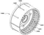
한편, 도 2에서는 본 발명의 제1실시예에 대비되는 회전자 슬리브(1400)의 비교예를 도시하고 있다. Meanwhile, Figure 2 shows a comparative example of the
도 2에 따른 구동모터의 회전자 슬리브(1400)는 스플라인 돌기(1402)와 스플라인 골(1401)을 포함하는 내측면의 기본 구조는 동일하나, 회전자 슬리브(1400)의 내측면에 형성되는 관통홀(1403) 및 외측면의 슬롯부(1404) 형상 등에서 차이를 보인다.The
도 2을 참조하면, 비교예에 따른 회전자 슬리브(1400)는 슬리브 내외측을 관통하는 관통홀(1403)을 스플라인 골(1401) 부분에 생성하고 슬리브 외측에 축방향 슬롯(Slot) 모양의 홈가공을 통해 슬롯부(1404)를 형성하는 방식으로 제작된다. Referring to FIG. 2, the
즉, 도 2에서와 같은 회전자 슬리브(1400)의 경우, 모터 회전 시, 회전자 슬리브(1400)의 내측벽면으로 유입된 오일 중 일부는 스플라인 골(1401)을 통해 변속기 측으로 배출된다. 한편, 오일 중 일부는 스플라인 골(1401)에 형성된 관통홀(1403)을 통해 회전자 슬리브(1400) 외측으로 이동하고, 외측의 슬롯부(1404)를 통해 배출구(1405) 측으로 배출되어 엔진 측으로 오일이 비산된다.That is, in the case of the
비교예에 따른 회전자 슬리브(1400)의 제작 방식의 경우, 엔진측으로 비산되는 유로 하나를 생성하기 위해 관통홀 가공과 슬리브 원주에 슬롯가공을 동시에 실시해야 한다. 따라서, 엔진 측 비산 유로의 개수 만큼 가공비가 증가하는 단점이 있어 그 수를 늘리는데 한계가 있다. In the case of the method of manufacturing the
예를 들어, 회전자 슬리브(1400) 내에 36개의 스플라인 골(1401)이 형성되고, 36개의 스플라인 골 중 6~8개에만 관통홀(1403)을 생성하는 경우, 엔진측 오일 공급이 미약한 편이다. 반면, 회전자 슬리브에 8개 이상의 관통홀(1403)을 생성하는 경우, 관통홀과 동일 개수의 슬롯부(1404) 가공을 실시하여야 하므로, 제작 공정이 복잡해지고, 제작 비용이 과도하게 높아진다. For example, when 36
한편, 도 3에서와 같이, 본 발명의 제1실시예에서는 회전자 슬리브(100) 내측에 형성되는 다수의 스플라인 골(101)들과 스플라인 돌기(102)들을 포함하는 내측 구조를 갖는다. 또한, 상기 다수의 스플라인 골(101)들 중 적어도 일부에는 관통홀(103)들이 형성된다.Meanwhile, as shown in FIG. 3, the first embodiment of the present invention has an inner structure including a plurality of
이러한 관통홀(103)은 회전자 슬리브(100) 내측면으로 흘러들어온 오일을 회전자 슬리브(100) 외측으로 전달하는 기능을 수행한다.This through
또한, 본 발명의 제1실시예에 따른 회전자 슬리브(100)의 경우, 회전자 슬리브(100) 외측면에 형성되는 슬롯부(105)와 이 슬롯부(105)로 유입된 오일이 엔진 측으로 공급될 수 있도록 하는 배출구(106)가 형성된다. 이러한 배출구(106)는 회전자 슬리브(100)의 외측 슬롯부(105)의 엔진 측 단부에 홈 가공을 통해 형성된다. 이 때, 회전자 슬리브(100) 외측에는 회전자 코어(200)가 고정되어 위치하며, 따라서, 슬롯부(105)에 형성된 홈과 회전자 코어(200)와의 접촉면에 의해 배출구(106)가 형성된다.In addition, in the case of the
제1실시예가 비교예와 구분되는 첫번째 특징은 회전자 슬리브(100) 외측면에 원주방향을 따라 환형의 홈(104)이 형성되는 것에 특징이 있다. 회전자 슬립의 외측면에 형성되는 환형의 홈(104)은 관통홀(103)들과 연통되며, 슬롯부(105)들을 서로 연결시켜 주기 때문에, 슬롯부(105)의 수를 크게 줄이는 데 기여하게 된다.The first feature that distinguishes the first embodiment from the comparative example is that an
구체적으로, 도 3에서와 같이, 회전자 슬리브(100)의 외측면의 원주 방향을 따라 형성되는 환형의 홈(104)은 회전자 슬리브(100) 내측면과 외측면을 관통하는 관통홀(103)들에 연결된다. 또한, 상기 환형의 홈(104)은 오일을 엔진 측으로 배출하기 위한 슬롯부(105)들에 연결된다. Specifically, as shown in FIG. 3, the
즉, 도 3에서와 같이, 환형의 홈(104)은 관통홀(103)들의 위치에 정확하게 일치하도록 형성되어야 하며, 이를 위해, 상기 관통홀(103)들은 축방향으로 동일한 위치에 형성되어야 한다. 따라서, 모든 관통홀(103)들은 원주 방향으로 일렬로 정렬되며, 원주 방향의 환형의 홈(104)에 정확하게 연통되도록 위치한다. 이러한 구조를 통해, 모든 관통홀(103)들을 통과한 오일은 회전자 슬리브(100) 외측의 환형 홈으로 유입된다. That is, as shown in FIG. 3, the
한편, 환형의 홈(104)들은 회전자 슬리브(100) 외측면에서 축방향을 따라 연장되어, 엔진 측으로 연장되는 슬롯부(105)에 연결된다. 따라서, 환형의 홈(104)으로 유입된 오일은 슬롯부(105)를 통해 배출구(106)로 배출되어 엔진 측으로 비산된다. 도 3의 제1실시예의 경우, 회전자 슬리브(100) 내측면에는 36개의 스플라인 골(101)이 형성되고 이 중 절반의 스플라인 골(101)에 18개의 관통홀(103)이 형성된다. 바람직하게는 각각의 슬롯부(105)는 상기 배출구(106)로 연결되는 축방향 슬롯을 포함하고, 상기 축방향 슬롯의 수는 상기 관통홀(103)의 수 보다 적게 형성된다.Meanwhile, the
본 구현예에 따르면, 관통홀(103)들의 개수에 비해 상대적으로 적은 수의 슬롯부(105)를 형성하더라도 모든 관통홀(103)을 통해 배출되는 오일 전체가 엔진 측으로 원활하게 배출될 수 있다.According to this embodiment, even if a relatively small number of
그러므로, 제1실시예에 따른 회전자 슬리브(100)를 제작하는 경우, 축방향의 슬롯 가공 개수는 유지하거나 감소시키더라도, 슬리브 내에서 오일이 유입 될 수 있는 슬리브 관통홀(103) 개수를 충분히 증가시켜 엔진측으로 비산되는 오일의 양을 늘릴 수 있는 장점이 있다. 따라서, 본 발명의 바람직한 구현예에서는 축방향 슬롯부(105)의 개수를 충분히 줄이도록 구성하는 바, 슬롯부(105)의 수에 비해 관통홀(103)의 개수가 더 많아지도록 형성된다. 따라서, 상기 슬롯부(105)들 중 적어도 하나는 2 이상의 관통홀(103)들과 연결되어야 한다.Therefore, when manufacturing the
대비되는 비교예의 경우, 관통홀(1403)의 개수에 맞춰 슬롯부(1404)의 개수를 동일하게 증가시켜야 하므로, 가공이 어려운 슬롯부(1404) 가공 수가 증가하므로, 관통홀(1403)의 개수를 늘리는데 한계가 있었다.In the case of the comparative example, the number of
반면, 본 발명의 제1실시예에 따르면, 슬롯부(105) 개수를 적은 수로 유지하면서, 관통홀(103) 개수를 충분히 늘릴 수 있으므로, 엔진 측으로 비산되는 오일의 양을 크게 증가시킬 수 있다. 따라서, 종래 변속기 측에 비하여 냉각 효율이 떨어지던 엔진 측 모터 코일에 대한 냉각 효율을 증대시킬 수 있게 된다.On the other hand, according to the first embodiment of the present invention, the number of through
도 4는 도 3의 회전자 슬리브(100)의 일부에 대한 절개도이며, 회전자 슬리브(100) 내로 유입된 오일이 변속기 측 모터 코일과 엔진 측 모터 코일로 각각 흐르는 경로를 상세하게 도시하고 있다.Figure 4 is a cutaway view of a portion of the
도 4에 도시된 바와 같이, 회전자 슬리브(100)가 인풋 샤프트를 중심으로 회전하게 되면, 오일이 회전자 슬리브(100) 내측면 측으로 중력에 의해 하강한다.As shown in FIG. 4, when the
이 때, 스플라인 돌기(102) 사이에 위치한 스플라인 골(101)로 오일이 유입되게 되는데, 스플라인 골(101)로 유입된 오일은 엔진 측 또는 변속기 측으로 흐르게 된다.At this time, oil flows into the
구체적으로, 도 4에서 2점쇄선으로 표시된 선은 변속기 측 모터 코일로의 오일 흐름을 도시한 것이다. 도 4에서와 같이, 스플라인 골(101) 측으로 유입된 오일 중 일부는, 스플라인 골(101)을 따라 변속기 측, 즉 회전자 슬리브(100)의 개방단 측으로 흐르면서 회전자 슬리브(100) 외부로 배출된다. 따라서, 도 1에서와 같이, 스플라인 골(101)을 따라 배출된 오일은 변속기 측의 모터 코일을 냉각하게 된다.Specifically, the line indicated by the two-dash chain in FIG. 4 shows the oil flow to the motor coil on the transmission side. As shown in FIG. 4, some of the oil flowing into the
반면, 도 4에서 실선으로 표시된 선은 엔진 측 모터 코일로의 오일 흐름을 도시하고 있다. 특히, 도 4에 도시된 바와 같이, 스플라인 골(101) 측으로 유입된 오일 중 일부는, 앞서의 경우와 반대 방향, 즉 회전자 슬리브(100)의 폐쇄단 측인 엔진 측으로 상기 스플라인 골(101)을 따라 이동할 수 있다. 이 때, 일부 스플라인 골(101)에는 관통홀(103)이 형성되어 있으며, 이 관통홀(103)을 통해 회전자 슬리브(100) 외측으로 오일이 이동하게 된다. 앞서 설명한 바와 같이, 관통홀(103)들은 회전자 슬리브(100) 외측의 환형의 홈(104)에 연통되도록 형성되는 바, 관통홀(103)을 통과한 오일은 환형의 홈(104)으로 이동하게 된다. 또한, 환형의 홈(104)은 각각의 슬롯부(105)와 연통하고 있으므로, 환형의 홈(104)으로 이동한 오일은 각 슬롯부(105)로 이동하고, 최종적으로 배출구(106)를 통해 엔진 측 모터 코일로 비산된다.On the other hand, the solid line in FIG. 4 shows the oil flow to the motor coil on the engine side. In particular, as shown in FIG. 4, some of the oil flowing into the
이와 관련, 도 3 및 도 4의 예에서는 변속기 측 모터 코일로 비산되도록 오일을 유도하는 제1 그룹의 스플라인 골(101a)과 엔진 측 모터 코일로 비산되도록 오일을 유도하는 제2그룹의 스플라인 골(101b)이 교대로 형성된 것에 특징이 있다. 제1 그룹의 스플라인 골(101a)은 관통홀(103)이 형성된 것이고, 제2 그룹의 스플라인 골(101b)은 관통홀(103)이 형성되지 않은 것이다.In this regard, in the examples of FIGS. 3 and 4, a first group of
본 발명의 바람직한 구현예에 따르면, 제1 그룹과 제2 그룹의 스플라인 골(101a, 101b)들에서의 오일 유동을 원활하게 하기 위해, 각 그룹에서의 축방향 유로 구배를 서로 다르게 설정하는 것에 또 다른 특징이 있다. 특히, 유로 구배를 서로 달리 구성함으로써, 리테이너(400)와 스플라인 골(101) 사이의 갭의 크기가 달라지게 된다.According to a preferred embodiment of the present invention, in order to smooth the oil flow in the
이와 관련 도 5 내지 도 8에서는 서로 다른 축방향 유로 구배를 통해 리테이너(400)와 스플라인 골(101) 사이의 갭이 제1 그룹과 제2 그룹 간에 달라지게 되는 것을 도시하고 있다.In relation to this, FIGS. 5 to 8 show that the gap between the
먼저, 도 5는 본 발명의 제1실시예에 따른 회전자 슬리브(100)에 리테이너(400) 및 엔진클러치가 조립된 상태를 도시한 절개도이다.First, Figure 5 is a cutaway view showing the
도 5에서와 같이, 회전자 슬리브(100)의 변속기 측 개방단에는 리테이너(400)가 조립되며, 리테이너(400)와 회전자 슬리브(100)의 스플라인 골(101) 사이의 갭을 통해 오일이 변속기 측 모터 코일로 비산된다. 도 5에서와 같이, 본 발명의 바람직한 구현예에 따르면, 제1 그룹의 스플라인 골(관통홀이 형성된 것)과 제2 그룹의 스플라인 골(관통홀이 형성되지 않은 것)이 서로 교대로 배치된다. 본 구현예의 경우, 제1 그룹의 갭(d1)과 제2 그룹의 갭(d2)는 서로 다른 갭 사이즈를 가진다.As shown in FIG. 5, a
구체적으로, 회전자 슬리브(100)의 스플라인 골(101)의 구배를 조정할 경우, 리테이너(400)와 스플라인 골(101) 사이의 갭 사이즈를 적절히 조절할 수 있다. 일반적으로, 회전자 슬리브(100)의 개방단(변속기 측 단부)으로는 오일이 변속기 측으로 흐를 수 있도록 구배를 형성하게 된다. 이 때, 스플라인 골의 구배를 크게 할 경우, 스플라인 골과 리테이너 사이의 갭 사이즈가 커지게 된다. 반면, 스플라인 골의 구배를 작게 할 경우, 스플라인 골과 리테이너 사이의 갭 사이즈가 작아진다.Specifically, when adjusting the gradient of the
구체적으로, 회전자 슬리브(100) 내측으로 비산된 오일이 슬리브 내측의 스플라인 골(101)로 모여 회전자 슬리브(100)와 리테이너(400) 조립 틈새를 통해 원활히 배출되어야 한다. 이와 관련, 도 7에서는 관통홀(103)이 형성되지 않은 제2그룹의 스플라인 골에서의 단면을 도시하고 있다. 도 7에서와 같이, 제2 그룹의 스플라인 골(101b)에는 축방향으로 비교적 큰 구배(약1.5˚)를 부여하는 것이 바람직하다. 축방향 구배를 적절히 크게 할 경우, 스플라인 골에 모인 오일이 리테이너 쪽(변속기 측)으로 원활히 흐름과 동시에 회전자 슬리브(100)와 리테이너(400) 조립 틈새를 크게 할 수 있어 오일이 원활히 배출된다. Specifically, the oil scattered inside the
반면, 도 6은 관통홀(103)이 형성된 제1그룹의 스플라인 골에서의 단면을 도시한 것이다. 본 발명의 바람직한 구현예에 따르면, 제1그룹의 스플라인 골에는 외부 슬롯부(105)로 빠져나갈 수 있는 오일의 관통홀(103)이 스플라인 골의 안쪽(스플라인 골의 전체길이에서 리테이너 조립 반대 방향)에 형성되어 있다. 따라서, 제1 그룹의 스플라인 골(101a)의 경우, 오일이 그 구멍으로 원활히 흐를 수 있도록 골에 생성된 구배를 최소화하는 것이 바람직하다. On the other hand, Figure 6 shows a cross section of the first group of spline valleys in which the through
구체적으로, 도 6에서와 같이 엔진 측으로 오일이 유입되는 관통홀(103)은 스플라인 골(101)의 안쪽에 위치 하고 있다. 또한, 회전자 슬리브(100) 내부로 비산된 오일이 상기 관통홀(103)로 잘 흘러 들어갈 수 있도록 도 6에서와 같이 스플라인 길이 방향 구배를 최소화한다. 따라서, 회전자 슬리브(100)와 리테이너(400) 조립 틈새를 작게(0.5㎜이하) 함으로써 대부분의 오일이 관통홀(103)로 유입 될 수 있도록 구성할 수 있다.Specifically, as shown in FIG. 6, the through
또한, 상기 관통홀(103)들은 상기 리테이너(400)의 조립 방향을 기준으로, 상기 스플라인 골(101)의 중심 보다 더 안쪽에 위치하도록 구성할 수 있다. 이와 같이 관통홀(103)을 최대한 회전자 슬리브(100)의 폐쇄단 측, 즉 엔진 측에 가깝게 형성함으로써 스플라인 골(101)의 유로를 최대한 활용할 수 있으며, 따라서 상대적으로 슬롯부(105)의 길이가 짧아지게 할 수 있다. 짧아진 슬롯부(105)의 길이는 오일의 유동 성능을 개선하고, 제작 공정을 보다 단순화시키는 데 기여한다.Additionally, the through
도 8을 참조하면, 슬리브 내측에 생성된 스플라인 골(101) 중에서 유입구멍의 유무에 따라 스플라인 골(101)의 축방향 구배를 달리하여 엔진측으로 오일이 배출되는 갭의 크기를 서로 다르게 함으로써, 각 그룹에서의 오일 배출 양을 조절 할 수 있다. Referring to FIG. 8, among the
특히, 도 6 및 도 7에서는 변속기 측 모터 코일로 비산되는 오일에 대한 흐름 경로 및 엔진 측 모터 코일로 비산되는 오일 흐름 경로를 비교하여 보여준다.In particular, Figures 6 and 7 show a comparison of the flow path for oil flying into the transmission-side motor coil and the oil flow path flying into the engine-side motor coil.
앞서 설명한 바와 같이, 두 그룹의 스플라인 골 중에서 변속기측 배출부(제2 그룹)은 스플라인 골에 생성된 축방향의 큰 구배를 통해 오일이 바깥쪽(리테이너 쪽)으로 원활히 흐르고, 회전자 슬리브(100)와 리테이너(400) 사이에 상대적으로 큰 갭(d2)의 조립 틈새를 통해 오일이 배출될 수 있다(도 7 참조). As described above, among the two groups of spline grooves, the transmission side discharge portion (second group) allows oil to flow smoothly outward (toward the retainer) through a large axial gradient created in the spline groove, and the rotor sleeve (100) Oil may be discharged through the assembly gap of the relatively large gap d2 between ) and the retainer 400 (see FIG. 7).
반면, 도 6에서와 같이, 엔진 측 배출부는 스플라인 골(101)의 축방향 구배를 최소화하여 회전자 슬리브(100)와 리테이너(400) 조립 틈새가 작아지게 되고, 관통홀(103)로 오일이 원활히 흐를 수 있게 된다. 즉, 도 6와 같은 스플라인 골에서는, 조립 틈새 측으로 흐르는 오일량이 도 7의 경우에 비해 줄어드는 반면, 상대적으로 관통홀(103)로 배출되는 오일량은 늘어나게 된다. 이후, 관통홀(103)로 흐른 오일은 원주방향의 환형의 홈(104)으로 모여 자연스럽게 슬롯부(105)를 통해 외측으로 빠져나가고, 이후 엔진 측 모터 코일로 비산된다.On the other hand, as shown in FIG. 6, the engine side discharge portion minimizes the axial gradient of the
따라서, 도 5 및 도 8에서와 같이, 엔진 측과 변속기 측으로 흐르는 오일 유량을 비슷한 수준으로 조절하기 위해, 관통홀(103)이 형성되지 않은 제2 그룹의 갭(d2)는 관통홀(103)이 형성된 제1 그룹의 갭(d1) 에 비하여 더 크게 형성되는 것이 바람직하다.Therefore, as shown in FIGS. 5 and 8, in order to adjust the oil flow rate flowing to the engine side and the transmission side to a similar level, the gap d2 of the second group in which the through
한편, 도 9 내지 도 12에서는 본 발명의 또 다른 구현예에 따른 회전자 슬리브(100)를 도시하고 있다. 특히, 도 9 및 도 10은 회전자 슬리브(100) 외측면의 환형의 홈(104)과 슬롯부(105)의 구조는 제1실시예와 동일하다. 다만, 도 9 및 도 10의 예의 경우, 회전자 슬리브(100)의 내측면의 스플라인 골 상에 형성되며, 원주면을 관통하는 관통홀(103)의 개수에서 차이가 있다.Meanwhile, Figures 9 to 12 show a
구체적으로, 도 9는 본 발명의 제2실시예에 따른 회전자 슬리브(100)에 대한 것으로, 도 9의 예에서는 회전자 슬리브(100)의 모든 스플라인 골에 관통홀(103)이 형성된 예를 도시하고 있다. 이 경우, 모든 스플라인 골(101)에 관통홀(103)이 형성되어 있으므로, 관통홀(103)의 크기 등의 조건에 따라 엔진 측 모터 코일로의 오일 비산량이 과도해질 수도 있다. 한편, 도 8에서와 같이, 일부 스플라인 골의 축방향 구배를 달리 적용하여 회전자 슬리브(100)와 리테이너(400) 사이의 조립 틈새의 갭 크기를 조절할 수도 있다. 이 경우, 스플라인 골의 축방향 구배에 따라 변속기 측 모터 코일로의 오일 비산량을 적절히 증가시킬 수 있다.Specifically, Figure 9 shows the
또한, 도 10에서는 본 발명의 제3실시예에 따른 회전자 슬리브(100)를 도시하고 있다. 도 10의 경우, 관통홀(103)이 형성된 제1그룹과 관통홀(103)이 형성되지 않은 제2그룹의 스플라인 골들을 모두 포함하고 있으며, 관통홀(103)이 형성된 제1그룹의 스플라인 골들 사이에는 두 개의 제2그룹의 스플라인 골들이 위치하는 것에 특징이 있다. 즉, 도 9의 제3실시예의 경우, 연속하는 3개의 스플라인 골 당 관통홀(103)이 형성된 예이다.Additionally, Figure 10 shows a
제3실시예의 경우, 앞서 제2실시예에 비하여 엔진 측 모터 코일로의 오일 비산량을 감소시킬 수 있다. 또한, 앞서 제2실시예의 경우와 마찬가지로, 각 스플라인 골(101)에 대한 축방향 구배를 적절히 조절하여 변속기 측 오일 비산량을 증감시킬 수 있다.In the case of the third embodiment, the amount of oil flying into the motor coil on the engine side can be reduced compared to the second embodiment. In addition, as in the case of the second embodiment, the amount of oil scattering on the transmission side can be increased or decreased by appropriately adjusting the axial gradient for each
한편, 도 11과 도 12는 제1실시예에 포함된 환형의 홈(104) 대신, 원주 방향의 일부 영역으로만 연장된 원주 방향 슬롯을 포함하는 예를 도시한 것이다.Meanwhile, Figures 11 and 12 show an example that includes a circumferential slot extending only to a portion of the circumferential direction, instead of the
이와 관련, 도 11은 본 발명의 제4실시예에 따른 회전자 슬리브(1100)를 도시한 것으로, 도 11에서는 상기 슬롯부가 "T"자 형상으로 이루어진 예를 도시하고 있다. In this regard, Figure 11 shows a
구체적으로, 도 11을 참조하면, 축방향 슬롯부만을 포함하는 제1실시예와는 달리, 슬롯부는 축방향 슬롯(1105)에 연결되는 원주 방향 슬롯(1104)을 더 포함하는 것을 특징으로 한다. 이러한 원주 방향 슬롯(1104)은 제1실시예의 환형의 홈(104)과 실질적으로 동일한 기능을 수행하는 것으로, 상기 원주 방향 슬롯은 다수의 관통홀(1103)들과 연결되도록 형성된다. 따라서, 도 11에 도시된 실시예 또한, 관통홀의 개수와 동일한 수의 슬롯부를 포함할 필요가 없으며, 관통홀(1103)에 비하여 상대적으로 적은 숫자의 축방향 슬롯(1105)을 형성하더라도, 비교예와 대등한 수준의 엔진 측 오일 비산량을 확보할 수 있다. 축방향 슬롯(1105)의 끝단에는 배출구(1106)가 형성된다.Specifically, referring to FIG. 11, unlike the first embodiment including only the axial slot portion, the slot portion further includes a
한편, 도 11의 제4실시예의 경우, 회전자 슬리브의 내측면 구조는 도 9의 제2실시예와 동일하게 형성되어 있다. 따라서, 제4실시예에서는 모든 스플라인 골(1101)들에 관통홀(1103)이 형성되어 있다. 다만, 관통홀의 개수는 적절히 조절될 수 있으며, 예를 들어 도 3의 제1실시예 또는 도 10의 제3실시예에서와 같이 관통홀이 형성될 수 있다. 또한, 스플라인 골(1101)의 축방향 구배 또한 앞서의 예들과 같이 적절히 조절될 수 있다. 도면 부호 1102는 스플라인 돌기를 나타낸다.Meanwhile, in the case of the fourth embodiment of FIG. 11, the inner surface structure of the rotor sleeve is formed the same as the second embodiment of FIG. 9. Accordingly, in the fourth embodiment, through
또한, 도 12는 본 발명의 제5실시예에 따른 회전자 슬리브(1200)를 도시한 것으로, 도 12에서는 슬롯부가 "ㄱ"자 형상인 구동모터의 회전자 슬리브(1200)를 도시하고 있다. 도 12의 예에서는 슬롯부의 형상을 제외하고는 도 11의 예와 차이점이 없다. 즉, 도 12의 예에서는 축방향 슬롯(1205)과 원주 방향 슬롯(1204)이 서로 연결되어 "ㄱ"자형 슬롯부를 형성하는 것에 특징이 있다. 또한, 축방향 슬롯의 끝단에는 배출구(1206)이 형성되어 있으며, 모든 스플라인 골(1201)에는 관통홀(1203)이 형성되어 있다. 관통홀의 개수 및 스플라인 골의 축방향 구배가 적절히 변경될 수 있음은 앞서 제4실시예에서 설명한 바와 같다. 도면부호 1202는 스플라인 돌기를 나타낸다.In addition, Figure 12 shows a
이상 살펴본 바와 같이, 도 11 및 도 12의 예에서는 원주방향의 환형의 홈을 가공하지 않고, 회전자 슬리브 외측에 "T"자형 슬롯부 또는 ㄱ"자형 슬롯부를 가공하여 슬롯 1개 가공 시 3~4개의 관통홀들로부터 오일이 연속적으로 유입될 수 있도록 구성할 수 있다.As discussed above, in the examples of FIGS. 11 and 12, the circular groove in the circumferential direction is not machined, but a “T”-shaped slot or an “L”-shaped slot is machined on the outside of the rotor sleeve, so that when machining one slot, 3~ It can be configured to allow oil to flow continuously from four through holes.
따라서, 도 11 및 도 12의 실시예에 따르면, 본 방법은 슬롯 개수를 최대한 줄여 가공비를 절감 하면서 오일유입 구멍의 개수를 최대로 할 수 있으며, 회전자 슬리브에 원주방향 환형의 홈을 형성하지 않을 수 있기 때문에, 회전자 슬리브의 강성 저하를 방지할 수 있는 장점이 있다.Therefore, according to the embodiment of Figures 11 and 12, this method can maximize the number of oil inlet holes while reducing processing costs by reducing the number of slots as much as possible, and does not form a circumferential annular groove in the rotor sleeve. Therefore, there is an advantage in preventing a decrease in the rigidity of the rotor sleeve.
본 발명은 바람직한 실시 예를 참조하여 설명하였지만, 해당 기술분야의 숙련된 당업자는 본 발명의 범위를 벗어나지 않는 범위 내에서 본 발명의 요소들에 대한 수정 및 변경의 가능함을 이해할 수 있을 것이다. 또한, 본 발명의 필수적인 영역을 벗어나지 않는 범위 내에서 특별한 상황들이나 재료에 대하여 많은 변경이 이루어질 수 있다. 그러므로, 본 발명은 본 발명의 바람직한 실시 예의 상세한 설명으로 제한되지 않으며, 첨부된 특허청구범위 내에서 모든 실시 예들을 포함할 것이다.Although the present invention has been described with reference to preferred embodiments, those skilled in the art will understand that modifications and changes can be made to elements of the present invention without departing from the scope of the present invention. Additionally, many changes may be made to special circumstances or materials without departing from the essential scope of the present invention. Therefore, the present invention is not limited to the detailed description of the preferred embodiments of the present invention, but will include all embodiments within the scope of the appended claims.
11: 고정자 코어 12: 코일
13: 회전자 슬리브 14: 엔진 클러치
15: 리테이너 16: 인풋 샤프트
100: 회전자 슬리브 101: 스플라인 골
102: 스플라인 돌기 103: 관통홀
104: 환형의 홈 105: 슬롯부
106: 배출구 200: 회전자 코어
300: 엔진 클러치 400: 리테이너11: stator core 12: coil
13: rotor sleeve 14: engine clutch
15: retainer 16: input shaft
100: rotor sleeve 101: spline groove
102: Spline protrusion 103: Through hole
104: Annular groove 105: Slot portion
106: outlet 200: rotor core
300: engine clutch 400: retainer
Claims (12)
상기 다수의 스플라인 골들 중 적어도 일부에 형성된 관통홀들;
상기 회전자 슬리브 외측에 형성되며, 상기 관통홀들을 통해 유입된 유체를 배출구 측으로 안내하도록 형성된 2 이상의 슬롯부들;을 포함하고,
상기 슬롯부들 중 적어도 하나는 2 이상의 관통홀들과 연결되고,
상기 관통홀들은 축방향으로 동일한 위치에 형성되며,
상기 회전자 슬리브의 외측 둘레를 따라 형성된 환형의 홈을 더 포함하고,
상기 홈은 상기 관통홀들에 연결되는 것을 특징으로 하는 구동모터의 회전자 슬리브.
A plurality of spline grooves formed inside the rotor sleeve of the drive motor;
Through holes formed in at least some of the plurality of spline grooves;
It includes two or more slot portions formed on the outside of the rotor sleeve and configured to guide fluid introduced through the through holes toward the outlet,
At least one of the slot parts is connected to two or more through holes,
The through holes are formed at the same position in the axial direction,
Further comprising an annular groove formed along an outer circumference of the rotor sleeve,
The rotor sleeve of a drive motor, characterized in that the groove is connected to the through holes.
각각의 슬롯부는 상기 배출구로 연결되는 축방향 슬롯을 포함하고, 상기 축방향 슬롯의 수는 상기 관통홀의 수 보다 적은 것을 특징으로 하는 구동모터의 회전자 슬리브.
In claim 1,
A rotor sleeve for a drive motor, wherein each slot portion includes an axial slot connected to the outlet, and the number of axial slots is less than the number of through holes.
상기 회전자 슬리브는 상기 스플라인 골들을 통해 리테이너가 조립될 수 있도록 구성되고,
상기 관통홀들은 상기 리테이너의 조립 방향을 기준으로, 상기 스플라인 골의 중심 보다 더 안쪽에 위치하는 것을 특징으로 하는 구동모터의 회전자 슬리브.
In claim 1,
The rotor sleeve is configured so that a retainer can be assembled through the spline grooves,
The rotor sleeve of the drive motor, wherein the through holes are located further inside the center of the spline groove, based on the assembly direction of the retainer.
상기 슬롯부는 상기 축방향 슬롯에 연결되는 원주 방향 슬롯을 더 포함하고, 원주 방향 슬롯은 다수의 관통홀들과 연결되도록 형성되는 것을 특징으로 하는 구동모터의 회전자 슬리브.
In claim 2,
The rotor sleeve of a drive motor, wherein the slot portion further includes a circumferential slot connected to the axial slot, and the circumferential slot is formed to be connected to a plurality of through holes.
상기 슬롯부는 "T"자 형상 또는 "ㄱ"자 형상인 것을 특징으로 하는 구동모터의 회전자 슬리브.
In claim 6,
The rotor sleeve of a drive motor, characterized in that the slot portion is a “T” shape or an “L” shape.
상기 다수의 스플라인 골들에는 각각 대응되는 관통홀이 형성된 것을 특징으로 하는 구동모터의 회전자 슬리브.
In claim 1,
A rotor sleeve of a drive motor, characterized in that corresponding through holes are formed in each of the plurality of spline grooves.
상기 다수의 스플라인 골들은 관통홀이 형성된 제1그룹과 관통홀이 형성되지 않은 제2그룹으로 구분되고, 상기 제1그룹의 축방향 구배는 상기 제2그룹의 축방향 구배와 서로 다른 것을 특징으로 하는 구동모터의 회전자 슬리브.
In claim 1,
The plurality of spline valleys are divided into a first group in which through holes are formed and a second group in which through holes are not formed, and the axial gradient of the first group is different from the axial gradient of the second group. The rotor sleeve of the driving motor.
상기 제1그룹의 축방향 구배는 상기 제2그룹의 축방향 구배 보다 더 작은 것을 특징으로 하는 구동모터의 회전자 슬리브.
In claim 9,
The rotor sleeve of the drive motor, characterized in that the axial gradient of the first group is smaller than the axial gradient of the second group.
상기 제1그룹의 스플라인 골들 사이에는 상기 제2그룹의 스플라인 골이 배치되고, 상기 제1그룹의 스플라인 골들 사이에 배치되는 상기 제2그룹의 스플라인 골의 수는 동일한 것을 특징으로 하는 구동모터의 회전자 슬리브.
In claim 9,
The second group of spline valleys are disposed between the first group of spline valleys, and the number of the second group of spline valleys arranged between the first group of spline valleys is the same. Electronic sleeve.
코일이 감겨진 고정자 코어;를 포함하는 구동 모터.
A rotor sleeve of a drive motor according to any one of claims 1, 2, 3, 6 to 11; and
A drive motor comprising a stator core with a coil wound around it.
Priority Applications (2)
| Application Number | Priority Date | Filing Date | Title |
|---|---|---|---|
| KR1020180139264A KR102621527B1 (en) | 2018-11-13 | 2018-11-13 | Rotor sleeve for motor and motor for vehicle including the same |
| US16/450,394 US10971961B2 (en) | 2018-11-13 | 2019-06-24 | Rotor sleeve of driving motor and driving motor including the same |
Applications Claiming Priority (1)
| Application Number | Priority Date | Filing Date | Title |
|---|---|---|---|
| KR1020180139264A KR102621527B1 (en) | 2018-11-13 | 2018-11-13 | Rotor sleeve for motor and motor for vehicle including the same |
Publications (2)
| Publication Number | Publication Date |
|---|---|
| KR20200055523A KR20200055523A (en) | 2020-05-21 |
| KR102621527B1 true KR102621527B1 (en) | 2024-01-04 |
Family
ID=70551890
Family Applications (1)
| Application Number | Title | Priority Date | Filing Date |
|---|---|---|---|
| KR1020180139264A KR102621527B1 (en) | 2018-11-13 | 2018-11-13 | Rotor sleeve for motor and motor for vehicle including the same |
Country Status (2)
| Country | Link |
|---|---|
| US (1) | US10971961B2 (en) |
| KR (1) | KR102621527B1 (en) |
Families Citing this family (2)
| Publication number | Priority date | Publication date | Assignee | Title |
|---|---|---|---|---|
| WO2022115058A1 (en) * | 2020-11-30 | 2022-06-02 | Dereli Izzet | An arrangement for alternators or electric motors |
| JP2024007149A (en) * | 2022-07-05 | 2024-01-18 | 株式会社アイシン福井 | torque limiter |
Citations (2)
| Publication number | Priority date | Publication date | Assignee | Title |
|---|---|---|---|---|
| US20030030333A1 (en) | 2001-08-08 | 2003-02-13 | Johnsen Tyrone A. | Cooling of a rotor for a rotary electric machine |
| JP2013046463A (en) | 2011-08-23 | 2013-03-04 | Aisin Seiki Co Ltd | Rotary electric machine |
Family Cites Families (16)
| Publication number | Priority date | Publication date | Assignee | Title |
|---|---|---|---|---|
| US3629628A (en) * | 1970-07-06 | 1971-12-21 | Gen Motors Corp | Cooling arrangement for a squirrel cage rotor assembly |
| US4418777A (en) * | 1981-09-11 | 1983-12-06 | Ford Motor Company | Transmission lubrication and motor cooling system |
| US4602177A (en) * | 1984-12-20 | 1986-07-22 | Westinghouse Electric Corp. | Homopolar generators with thermosyphons for improved cooling |
| US5189325A (en) * | 1990-06-15 | 1993-02-23 | General Electric Company | Liquid cooling the rotor of an electrical machine |
| US6879069B1 (en) * | 2000-06-21 | 2005-04-12 | Bae Systems Controls Inc. | Rotating machine with cooled hollow rotor bars |
| JP4492745B2 (en) * | 2008-10-27 | 2010-06-30 | トヨタ自動車株式会社 | Rotating electric machine |
| KR101129668B1 (en) | 2009-10-28 | 2012-03-28 | 한국파워트레인 주식회사 | multi-plate clutch device for automatic transmission |
| EP2562914A4 (en) * | 2010-04-23 | 2016-06-22 | Ihi Corp | Rotating machine |
| KR101475369B1 (en) * | 2010-12-22 | 2014-12-23 | 가부시키가이샤 아이에이치아이 | Rotary machine |
| US8497608B2 (en) * | 2011-01-28 | 2013-07-30 | Remy Technologies, Llc | Electric machine cooling system and method |
| JP5139562B2 (en) * | 2011-06-24 | 2013-02-06 | ファナック株式会社 | Electric motor that can attach a sleeve to a rotating shaft with high accuracy |
| US9284882B2 (en) | 2012-02-10 | 2016-03-15 | Aisin Aw Co., Ltd. | Hybrid drive device |
| KR20140066880A (en) * | 2012-11-23 | 2014-06-03 | 현대자동차주식회사 | Apparatus for cooling a driving motor of hybrid electrical vehicle |
| DE102016222846A1 (en) * | 2016-11-21 | 2018-05-24 | Audi Ag | Electric machine |
| KR102563471B1 (en) * | 2016-12-14 | 2023-08-04 | 현대자동차주식회사 | Coil Surrounding Cooling type Drive Motor and Echo Vehicle thereby |
| KR102506753B1 (en) * | 2016-12-14 | 2023-03-07 | 현대자동차주식회사 | Oil Scatter Leading Cooling type Drive Motor and Echo Vehicle thereby |
-
2018
- 2018-11-13 KR KR1020180139264A patent/KR102621527B1/en active IP Right Grant
-
2019
- 2019-06-24 US US16/450,394 patent/US10971961B2/en active Active
Patent Citations (2)
| Publication number | Priority date | Publication date | Assignee | Title |
|---|---|---|---|---|
| US20030030333A1 (en) | 2001-08-08 | 2003-02-13 | Johnsen Tyrone A. | Cooling of a rotor for a rotary electric machine |
| JP2013046463A (en) | 2011-08-23 | 2013-03-04 | Aisin Seiki Co Ltd | Rotary electric machine |
Also Published As
| Publication number | Publication date |
|---|---|
| KR20200055523A (en) | 2020-05-21 |
| US10971961B2 (en) | 2021-04-06 |
| US20200153300A1 (en) | 2020-05-14 |
Similar Documents
| Publication | Publication Date | Title |
|---|---|---|
| US7009317B2 (en) | Cooling system for an electric motor | |
| US4334720A (en) | Split-inner-ring ball bearing with lubrication structure | |
| EP1390630B1 (en) | Oil annulus to circumferentially equalize oil feed to inner race of a bearing | |
| KR102621527B1 (en) | Rotor sleeve for motor and motor for vehicle including the same | |
| US11489409B2 (en) | Motor housing assembly | |
| CN101341346A (en) | Pressure plate with covered ducts for a torque converter, and method for cooling a pressure plate of said type | |
| SU1828527A3 (en) | Device for limiting supply of lubricant through coaxial passage of revolving shaft | |
| JP2013042661A (en) | Electric motor | |
| US9624984B2 (en) | Startup clutch lubrication system and method thereof | |
| CN111641281B (en) | Rotor of rotating electric machine | |
| US10655727B2 (en) | Lubricating device for a transmission, and transmission comprising said lubricating device | |
| US11056952B2 (en) | Electric machine with internal cooling passageways | |
| KR102618055B1 (en) | Rotor assembly and motor including the same | |
| KR102597215B1 (en) | Hybrid driving system | |
| CN111641284B (en) | Rotor of rotating electric machine | |
| CN217029232U (en) | Bearing cooling structure, bearing, compressor and refrigeration equipment | |
| JP5682704B2 (en) | Belt type continuously variable transmission | |
| US12027922B2 (en) | Rotor assembly and method for motor end winding cooling and bearing lubrication | |
| CN110360223B (en) | Air bearing | |
| JP2019097220A (en) | Rotary electric machine | |
| CN114759734A (en) | Oil cooling structure for magnet of motor and motor | |
| CN114251390A (en) | Wet friction disc | |
| KR102544771B1 (en) | Rotor assembly and motor including the same | |
| CN104723856B (en) | Hybrid power drive module with motor | |
| CN118316222A (en) | Motor rotor cooling structure |
Legal Events
| Date | Code | Title | Description |
|---|---|---|---|
| A201 | Request for examination | ||
| E902 | Notification of reason for refusal | ||
| E701 | Decision to grant or registration of patent right | ||
| GRNT | Written decision to grant |