KR102117746B1 - Mattress for preventing pressure sore - Google Patents
Mattress for preventing pressure sore Download PDFInfo
- Publication number
- KR102117746B1 KR102117746B1 KR1020180020370A KR20180020370A KR102117746B1 KR 102117746 B1 KR102117746 B1 KR 102117746B1 KR 1020180020370 A KR1020180020370 A KR 1020180020370A KR 20180020370 A KR20180020370 A KR 20180020370A KR 102117746 B1 KR102117746 B1 KR 102117746B1
- Authority
- KR
- South Korea
- Prior art keywords
- pressure
- control module
- mattress
- average value
- mode
- Prior art date
Links
Images


Classifications
-
- A—HUMAN NECESSITIES
- A61—MEDICAL OR VETERINARY SCIENCE; HYGIENE
- A61G—TRANSPORT, PERSONAL CONVEYANCES, OR ACCOMMODATION SPECIALLY ADAPTED FOR PATIENTS OR DISABLED PERSONS; OPERATING TABLES OR CHAIRS; CHAIRS FOR DENTISTRY; FUNERAL DEVICES
- A61G7/00—Beds specially adapted for nursing; Devices for lifting patients or disabled persons
- A61G7/05—Parts, details or accessories of beds
- A61G7/057—Arrangements for preventing bed-sores or for supporting patients with burns, e.g. mattresses specially adapted therefor
- A61G7/05769—Arrangements for preventing bed-sores or for supporting patients with burns, e.g. mattresses specially adapted therefor with inflatable chambers
- A61G7/05776—Arrangements for preventing bed-sores or for supporting patients with burns, e.g. mattresses specially adapted therefor with inflatable chambers with at least two groups of alternately inflated chambers
-
- A—HUMAN NECESSITIES
- A61—MEDICAL OR VETERINARY SCIENCE; HYGIENE
- A61G—TRANSPORT, PERSONAL CONVEYANCES, OR ACCOMMODATION SPECIALLY ADAPTED FOR PATIENTS OR DISABLED PERSONS; OPERATING TABLES OR CHAIRS; CHAIRS FOR DENTISTRY; FUNERAL DEVICES
- A61G2203/00—General characteristics of devices
- A61G2203/10—General characteristics of devices characterised by specific control means, e.g. for adjustment or steering
-
- A—HUMAN NECESSITIES
- A61—MEDICAL OR VETERINARY SCIENCE; HYGIENE
- A61G—TRANSPORT, PERSONAL CONVEYANCES, OR ACCOMMODATION SPECIALLY ADAPTED FOR PATIENTS OR DISABLED PERSONS; OPERATING TABLES OR CHAIRS; CHAIRS FOR DENTISTRY; FUNERAL DEVICES
- A61G2203/00—General characteristics of devices
- A61G2203/30—General characteristics of devices characterised by sensor means
- A61G2203/34—General characteristics of devices characterised by sensor means for pressure
Landscapes
- Health & Medical Sciences (AREA)
- Nursing (AREA)
- Life Sciences & Earth Sciences (AREA)
- Animal Behavior & Ethology (AREA)
- General Health & Medical Sciences (AREA)
- Public Health (AREA)
- Veterinary Medicine (AREA)
- Invalid Beds And Related Equipment (AREA)
Abstract
본 발명에 따른 욕창 방지용 매트리스는 적어도 두 개의 에어 셀로 구성된 공압 매트리스, 상기 공압 매트리스에 가해지는 압력을 측정하여 압력값을 생성하는 적어도 하나의 압력 센서 및 각각의 에어 셀과 연결된 공압 모터를 교번적으로 동작시켜 서로 이웃하는 에어 셀간의 교대부양을 제어하되, 상기 압력 센서로부터 수신되는 압력값에 따라 에어 셀의 교대부양 시간을 동적으로 변경하는 제어 모듈을 포함한다.The mattress for preventing bedsores according to the present invention alternately comprises a pneumatic mattress composed of at least two air cells, at least one pressure sensor that measures a pressure applied to the pneumatic mattress to generate a pressure value, and a pneumatic motor connected to each air cell. It controls the alternating flotation between neighboring air cells by operating, and includes a control module that dynamically changes the alternate flotation time of the air cells according to the pressure value received from the pressure sensor.
Description
본 발명은 욕창 방지용 매트리스에 관한 것으로서, 더욱 상세하게는 사용자 맞춤형 자세제어를 위한 동작을 수행하는 욕창 방지용 매트리스에 관한 것이다.The present invention relates to an anti-bedsore mattress, and more particularly, to an anti-bedsore mattress performing an operation for user-specific posture control.
욕창은 압박궤양으로도 불리우며, 고정된 자세로 앉아있거나 누워있을 때 특정 부위에 지속적인 압박이 가해짐으로써 혈액순환 장애가 발생하여 피하조직의 손상이 유발되는 현상을 일컫는다. 욕창은 의식이 없는 환자, 뇌신경이나 척수신경 손상이 있는 환자, 위중한 환자, 노인 환자, 만성 질환을 앓고 있는 환자, 만성적으로 쇠약해 있는 환자, 침대에 누워지내는 환자 등에서 잘 생긴다. 이러한 환자는 장시간 동일한 자세를 취해 있어도 압력을 받는 곳에 불쾌감을 느끼지 못하며, 불쾌감을 느낀다 해도 환자 자신이 자세를 바꿀 기력이 없기 때문에 압력에 의한 손상을 입기 쉽다. 이에, 환자의 욕창 방지 및 보호자의 노동을 감소시키기 위한 다양한 제품들이 제안된 바 있다.Pressure sores, also called pressure ulcers, refers to a phenomenon in which blood circulation disorder occurs and damage to the subcutaneous tissue occurs due to constant pressure applied to a specific area when sitting or lying in a fixed position. Bedsores are common in patients who are unconscious, patients with brain or spinal nerve damage, critical patients, elderly patients, patients with chronic diseases, chronically debilitating patients, and patients lying in bed. These patients do not feel discomfort in the place under pressure even when they are in the same posture for a long time. Even if they feel uncomfortable, they are susceptible to pressure damage because they do not have the ability to change their posture. Accordingly, various products have been proposed to prevent bedsores in patients and to reduce the caregiver's labor.
하지만, 종래에 제안된 제품들은 제품의 디자인 형태에 의해 압력을 해소하는 수동적인 제품들과 개방 루프(Open loop) 시스템의 제품들이 대부분을 차지하고 있다. 이러한 제품들은 미리 정해진 형상이나 항상 일정한 동작으로 압력을 해소하고자 하기 때문에, 환자의 현재 상태를 제대로 반영하지 못한다는 한계가 있다. 욕창 방지를 위해서는 환자의 특성에 파악하고, 이에 따라 환자 맞춤형 압력 해소 방법을 수행해야 하는 바, 자동으로 환자의 압력 부위를 파악하여 이에 적합한 압력 해소 방법을 동적으로 결정하는 제품이 개발될 필요가 있다.However, the products proposed in the related art are mostly passive products that relieve pressure by the design form of the products and products of an open loop system. These products have a limitation that they do not properly reflect the current state of the patient because they want to relieve pressure with a predetermined shape or a constant motion. In order to prevent bedsores, it is necessary to grasp the characteristics of the patient and perform a pressure relief method tailored to the patient accordingly. Therefore, it is necessary to develop a product that automatically identifies the pressure part of the patient and dynamically determines the appropriate pressure relief method. .
본 발명의 일측면은 폐쇄 루프(Closed loop) 시스템을 통해 다양한 동작모드를 가변적으로 수행하여 환자의 상태에 최적화된 동작모드에 따라 교대부양을 수행하는 욕창 방지용 매트리스를 제공한다.One aspect of the present invention provides a mattress for preventing bedsores performing alternate flotation according to an operation mode optimized for a patient's condition by variably performing various operation modes through a closed loop system.
본 발명의 기술적 과제는 이상에서 언급한 기술적 과제로 제한되지 않으며, 언급되지 않은 또 다른 기술적 과제들은 아래의 기재로부터 당업자에게 명확하게 이해될 수 있을 것이다.The technical problem of the present invention is not limited to the technical problem mentioned above, and other technical problems not mentioned will be clearly understood by those skilled in the art from the following description.
본 발명의 일 실시예에 따른 욕창 방지용 매트리스는, 적어도 두 개의 에어 셀로 구성된 공압 매트리스, 상기 공압 매트리스에 가해지는 압력을 측정하여 압력값을 생성하는 적어도 하나의 압력 센서 및 각각의 에어 셀과 연결된 공압 모터를 교번적으로 동작시켜 서로 이웃하는 에어 셀간의 교대부양을 제어하되, 상기 압력 센서로부터 수신되는 압력값에 따라 에어 셀의 교대부양 시간을 동적으로 변경하는 제어 모듈을 포함한다.Mattress for preventing bedsores according to an embodiment of the present invention, a pneumatic mattress consisting of at least two air cells, at least one pressure sensor to measure the pressure applied to the pneumatic mattress to generate a pressure value, and the air pressure connected to each air cell It includes a control module for operating the motor alternately to control the alternate flotation between neighboring air cells, but dynamically changes the alternate flotation time of the air cells according to the pressure value received from the pressure sensor.
상기 제어 모듈은 타이머 모드, 압력 모드 및 수동 모드 중 어느 하나의 모드로 동작하되, 서로 다른 위치에 배치된 상기 압력 센서로부터 수신되는 복수의 압력값의 평균값을 산출하고, 소정 시간 간격으로 산출된 복수의 평균값 중 최대 평균값이 미리 설정된 임계값을 초과하는 것을 판단되면 상기 최대 평균값의 크기에 따라 교대부양 시간을 동적으로 결정하는 상기 압력 모드가 활성화될 수 있다.The control module operates in any one of a timer mode, a pressure mode, and a manual mode, calculates an average value of a plurality of pressure values received from the pressure sensors disposed at different positions, and calculates a plurality of values calculated at predetermined time intervals. When it is determined that the maximum average value among the average values exceeds the preset threshold value, the pressure mode for dynamically determining the alternate flotation time according to the size of the maximum average value may be activated.
상기 제어 모듈은, 상기 압력 모드로 동작되는 구간 동안 상기 최대 평균값이 커질수록 교대부양 주기가 단축되도록, 공압 모터의 교번적인 동작 주기를 제어할 수 있다.The control module may control an alternating operation cycle of the pneumatic motor such that the alternate stimulation cycle is shortened as the maximum average value increases during a section operated in the pressure mode.
사용자 단말과 통신하는 통신 모듈을 더 포함하고, 상기 제어 모듈은, 상기 통신 모듈을 통해 상기 사용자 단말로부터 제어신호를 수신하면, 상기 제어신호에 따라 교대부양을 제어하는 상기 수동 모드가 활성화될 수 있다.Further comprising a communication module for communicating with a user terminal, the control module, when receiving a control signal from the user terminal through the communication module, the manual mode for controlling the shift in accordance with the control signal can be activated .
상기 제어 모듈은, 상기 최대 평균값이 미리 설정된 임계값 이하이면서, 소정 시간 동안 상기 제어신호가 수신되지 않는 것으로 확인되면 일정한 시간 간격으로 교대부양을 제어하는 상기 타이머 모드가 활성화될 수 있다.In the control module, when it is determined that the maximum average value is equal to or less than a preset threshold value and the control signal is not received for a predetermined time, the timer mode for controlling the shift levitation at regular time intervals may be activated.
상술한 본 발명의 일측면에 따르면, 압력값의 크기에 따라 동작 모드가 실시간으로 가변되어 사용자별로 최적화된 교대부양 시간을 자동으로 설정할 수 있으며, 이에 따라 환자의 욕창 발생을 효과적으로 예방할 수 있다.According to one aspect of the present invention described above, the operation mode is changed in real time according to the size of the pressure value to automatically set the optimal shift time for each user, and accordingly, it is possible to effectively prevent the patient's pressure sores.
도 1은 본 발명의 일 실시예에 따른 욕창 방지용 매트리스의 개략적인 구성이 도시된 도면이다.
도 2는 도 1의 제어 모듈의 구체적인 구성이 도시된 블록도이다.
도 3은 사용자 단말에 표시되는 화상정보의 일 예가 도시된 도면이다.
도 4는 제어 모듈이 압력 모드의 활성화 여부를 결정하는 구체적인 방법이 도시된 순서도이다.
도 5는 전후 방향의 교대부양에 따른 제1 에어 셀의 단면도이다.1 is a view showing a schematic configuration of a mattress for preventing bedsores according to an embodiment of the present invention.
FIG. 2 is a block diagram showing a specific configuration of the control module of FIG. 1.
3 is a diagram illustrating an example of image information displayed on a user terminal.
4 is a flowchart illustrating a specific method in which the control module determines whether to activate the pressure mode.
5 is a cross-sectional view of the first air cell according to the alternate flotation in the front-rear direction.
후술하는 본 발명에 대한 상세한 설명은, 본 발명이 실시될 수 있는 특정 실시예를 예시로서 도시하는 첨부 도면을 참조한다. 이들 실시예는 당업자가 본 발명을 실시할 수 있기에 충분하도록 상세히 설명된다. 본 발명의 다양한 실시예는 서로 다르지만 상호 배타적일 필요는 없음이 이해되어야 한다. 예를 들어, 여기에 기재되어 있는 특정 형상, 구조 및 특성은 일 실시예와 관련하여 본 발명의 정신 및 범위를 벗어나지 않으면서 다른 실시예로 구현될 수 있다. 또한, 각각의 개시된 실시예 내의 개별 구성요소의 위치 또는 배치는 본 발명의 정신 및 범위를 벗어나지 않으면서 변경될 수 있음이 이해되어야 한다. 따라서, 후술하는 상세한 설명은 한정적인 의미로서 취하려는 것이 아니며, 본 발명의 범위는, 적절하게 설명된다면, 그 청구항들이 주장하는 것과 균등한 모든 범위와 더불어 첨부된 청구항에 의해서만 한정된다. 도면에서 유사한 참조부호는 여러 측면에 걸쳐서 동일하거나 유사한 기능을 지칭한다.For a detailed description of the present invention, which will be described later, reference is made to the accompanying drawings that illustrate, by way of example, specific embodiments in which the present invention may be practiced. These examples are described in detail enough to enable those skilled in the art to practice the present invention. It should be understood that the various embodiments of the invention are different, but need not be mutually exclusive. For example, the specific shapes, structures, and properties described herein can be implemented in other embodiments without departing from the spirit and scope of the invention in connection with one embodiment. In addition, it should be understood that the location or placement of individual components within each disclosed embodiment can be changed without departing from the spirit and scope of the invention. Therefore, the following detailed description is not intended to be taken in a limiting sense, and the scope of the present invention, if appropriately described, is limited only by the appended claims, along with all ranges equivalent to those claimed. In the drawings, similar reference numerals refer to the same or similar functions throughout several aspects.
이하, 도면들을 참조하여 본 발명의 바람직한 실시예들을 보다 상세하게 설명하기로 한다.Hereinafter, preferred embodiments of the present invention will be described in more detail with reference to the drawings.
도 1은 본 발명의 일 실시예에 따른 욕창 방지용 매트리스(1)의 개략적인 구성이 도시된 도면이다.1 is a view showing a schematic configuration of a
구체적으로, 본 발명의 일 실시예에 따른 욕창 방지용 매트리스(1)는 공압 매트리스(100), 압력센서(200), 공압 모터(300) 및 제어모듈(400)을 포함한다.Specifically, the
공압 매트리스(100)는 환자와 직접 접촉하는 부분으로, 적어도 두 개의 에어 셀(110, 120)로 구성될 수 있다. 도시된 도면에서는 공압 매트리스(100)가 제1 에어 셀(110)과 제2 에어 셀(120)로 구성되었으나, 본 발명의 다른 실시예에서 공압 매트리스(100)는 세 개 이상의 에어 셀로 구성될 수도 있다.The
제1 에어 셀(110)과 제2 에어 셀(120)은 측면이 서로 인접되도록 배치될 수 있다. 일 예로, 제1 에어 셀(110)의 우측면과 제2 에어 셀(120)의 좌측면은 서로 마주보도록 배치될 수 있다. 이때, 제1 에어 셀(110)과 제2 에어 셀(120)간의 간격은 소정 거리 이하가 되도록 배치되거나 서로 접하도록 배치될 수 있다. The
각각의 에어 셀(110, 120)은 내부에 공기를 수용할 수 있는 공간이 마련되어 후술하는 공압 모터(300)에 의해 에어 셀(110, 120) 내부로 공기가 유입되거나 유입된 공기가 배출될 수 있다. 각각의 에어 셀(110, 120)은 복수의 서브 셀(S, S')들로 구성되고, 어느 하나의 서브 셀(S)은 이웃하는 서브 셀(S')과 서로 다른 높이를 갖도록 마련될 수 있다. 따라서, 각각의 에어 셀(110, 120)은 상부 표면이 굴곡된 형상을 가지게 될 수 있다.Each air cell (110, 120) is provided with a space for receiving air therein, the air may be introduced into the air cells (110, 120) or the introduced air may be discharged by the pneumatic motor (300) described later. have. Each air cell (110, 120) is composed of a plurality of sub-cells (S, S '), any one of the sub-cell (S) is provided to have a different height from the neighboring sub-cell (S') Can be. Therefore, each of the
공압 매트리스(100)의 하면에는 압력 감지 패드(250)가 배치될 수 있으며, 압력 감지 패드(250)에는 복수의 압력 센서(200)가 분산 배치될 수 있다. 즉, 압력 센서(200)는 공압 매트리스(100)의 하면에 배치되어 공압 매트리스(100)로 가해지는 압력을 감지할 수 있으며, 공압 매트리스(100)의 어느 부분에서 압력이 발생하는지를 감지할 수 있다. 압력 센서(200)는 후술하는 제어 모듈(400)과 유선 또는 무선으로 연결되어 측정된 압력값을 제어 모듈(400)로 전달할 수 있다.A
공압 모터(300)는 공압 매트리스(100)에 공기를 주입하는 모터로, 공압 모터(300)의 개수는 에어 셀의 개수에 따라 결정될 수 있다. 예를 들어, 도시된 바와 같이 공압 매트리스(100)가 두 개의 에어 셀(110, 120)로 구성된 경우 공압 모터(300) 또한 두 개로 마련되며, 하나의 공압 모터(300)는 하나의 에어 셀과 연결될 수 있다. 즉, 제1 공압 모터(310)는 제1 에어 셀(110)과 연결되고, 제2 공압 모터(320)는 제2 에어 셀(120)과 연결될 수 있다. The
이때, 공압 모터(310, 320)와 에어 셀(110, 120)은 공기가 왕복하는 튜브(312, 322)로 연결되어, 공압 모터(310, 320)에 의해 발생되는 공압에 의해 에어 셀(110, 120) 내부로 공기가 주입되거나 공압 모터(310, 320)가 작동하지 않는 경우 에어 셀(110, 120)에 주입된 공기가 튜브(312, 322)를 통해 배출될 수 있다.At this time, the
공압 모터(310, 320)와 에어 셀(110, 120) 사이에는 솔레노이드 밸브(311, 321)이 배치될 수 있다. 솔레노이드 밸브(311, 321)는 제어 모듈(400)에 의해 개폐가 제어될 수 있다. 솔레노이드 밸브(311, 321)가 개방되는 경우 에어 셀(110, 120)과 튜브(312, 322)와 연통되고, 솔레노이드 밸브(311, 321)가 닫히는 경우 에어 셀(110, 120)과 튜브(312, 322)가 차단되어 공기의 유통을 제어할 수 있다. 또한, 제1 공압 모터(310)와 제1 솔레노이드 밸브(311)의 사이, 제2 공압 모터(320)와 제2 솔레노이드 밸브(321)의 사이에는 각각 체크 밸브(미도시)가 설치되어, 공압 손실을 감소시키고 공압 모터(300)의 동작 도중 공기가 역방향으로 진행하는 것을 방지할 수 있다.
제어 모듈(400)은 본 발명에 따른 욕창 방지용 매트리스(1)의 전반적인 동작을 제어할 수 있다. 특히, 제어 모듈(400)은 공압 모터(300) 및 솔레노이드 밸브(311, 321)와 회로를 형성하고, 이를 통해 서로 다른 공압 모터(300)를 교번적으로 동작시킴으로써 에어 셀(110, 120)간의 교대부양을 제어할 수 있다. 이와 관련하여, 도 2를 함께 참조하여 설명하기로 한다.The
도 2는 도 1의 제어 모듈(400)의 구체적인 구성이 도시된 블록도이다.2 is a block diagram showing a specific configuration of the
구체적으로, 본 발명의 일 실시예에 따른 제어 모듈(400)은 MCU(410), 릴레이 스위치(420) 및 통신 모듈(430)을 포함한다. 이때, MCU(410), 릴레이 스위치(420) 및 통신 모듈(430)은 PCB 기판 상에 설치되며, PCB 기판은 아두이노 기반의 메인보드일 수 있으나, 이에 한정되는 것은 아니다.Specifically, the
MCU(Micro Controller Unit, 410)는 릴레이 스위치(420) 및 통신 모듈(430)과 연결되며, 통신 모듈(430)을 통해 제어 모듈(400)로 수신되는 데이터를 처리하여 그 결과에 따라 적어도 하나의 릴레이 스위치(420)를 제어하여 에어 셀(110, 120)간의 교대부양을 수행하거나, 처리된 결과를 통신 모듈(430)을 통해 외부 장치로 전송하도록 제어할 수 있다.The microcontroller unit (MCU) 410 is connected to the
릴레이 스위치(420)는 MCU(410)에 의해 제어되며, 어느 하나의 공압 모터(300) 또는 어느 하나의 솔레노이드 밸브와 전기적으로 연결될 수 있다. 예를 들어, 제1 릴레이 스위치(421)는 제1 공압 모터(310)와 연결되고, 제2 릴레이 스위치(422)는 제1 솔레노이드 밸브(311)와 연결되고, 제3 릴레이 스위치(423)은 제2 공압 모터(320)와 연결되며, 제4 릴레이 스위치(424)는 제2 솔레노이드 밸브(321)와 연결될 수 있다. 따라서, 제어 모듈(400)은 MCU(410)로부터 생성되는 제어 신호에 의해 릴레이 스위치(420)를 ON/OFF 시킴으로써 공압 모터를 교번적으로 동작시키거나 솔레노이드 밸브의 개방 또는 차단을 제어할 수 있다.The
구체적인 일 예로, MCU(410)는 제1 릴레이 스위치(421)를 ON시켜 제1 공압 모터(310)를 동작시키고, 제2 릴레이 스위치(422)를 ON시켜 제1 솔레노이드 밸브(311)가 개방되도록 제어함으로써 제1 에어 셀(110)에 공기가 유입되도록 제어할 수 있다. 이와 동시에, MCU(410)는 제3 릴레이 스위치(423)는 OFF 상태로 유지시켜 제2 구동 모터(320)가 작동되지 않도록 제어하면서, 제4 릴레이 스위치(424)는 ON시켜 제2 솔레노이드 밸브(252)를 개방하여 제2 에어 셀(120)에 저장된 공기가 제2 에어 셀(120)에 연결된 튜브(322)를 통해 빠져나가도록 제어할 수 있다. 이후, MCU(410)는 제1 공압 모터(310)를 통해 제1 에어 셀(110)에 충분한 공기가 유입된 것으로 판단되면, 제1 솔레노이드 밸브(311)를 차단시켜 제1 에어 셀(110)로 유입된 공기가 빠져나가지 못하도록 제어할 수 있다. 이에 따라, 제1 에어 셀(110)과 제2 에어 셀(120) 사이에 높이 차가 발생하여 높이 차가 발생한 부분에 위치한 환자의 신체에 대한 압력을 해소시킴으로써 욕창이 방지될 수 있다. As a specific example, the
이와 같은 방법으로, MCU(410)는 소정 시간 경과 후 제3 릴레이 스위치(423)를 ON시키되, 제1 릴레이 스위치(421)는 OFF 상태를 유지시켜 제2 에어 셀(120)에만 공기가 주입되도록 제어하여 제1 에어 셀(110)과 제2 에어 셀(120)에 교번적으로 공기를 주입시키는 교대부양을 수행할 수 있다.In this way, the
통신 모듈(430)은 외부 장치와 유선 또는 무선 통신을 수행할 수 있다. 구체적으로, 통신 모듈(430)은 복수의 압력 센서(200)와 통신을 수행하여 압력 센서(200)에 의해 측정된 압력값을 수신할 수 있다. The
또한, 통신 모듈(430)은 본 발명에 따른 욕창 방지용 매트리스(1)를 이용하는 환자, 간병인 또는 보호자가 소지한 사용자 단말과 통신할 수 있다. 통신 모듈(430)은 압력 센서(200)로부터 수신된 압력값 또는 제어 모듈(400)에 의해 생성된 데이터를 사용자 단말로 전송함으로써, 사용자는 사용자 단말을 이용하여 원격에서 욕창 상태를 확인하는 것이 가능하다. 이와 관련하여, 도 3을 함께 참조하여 설명하기로 한다.In addition, the
도 3은 사용자 단말에 표시되는 화상정보의 일 예가 도시된 도면이다.3 is a diagram illustrating an example of image information displayed on a user terminal.
사용자 단말은 통신 모듈(430)과 통신하기 위한 애플리케이션이 미리 설치될 수 있으며, 예를 들어 애플리케이션이 실행되는 경우 통신 모듈(430)로부터 수신된 데이터를 관리하는 관리서버에 접속하여 환자에 대한 다양한 정보를 사용자 단말의 화면으로 출력할 수 있다.The user terminal may be pre-installed with an application for communicating with the
도시된 실시예에서, 전체 페이지의 프런트엔드(front-end) 디자인은 웹에서 사용하는 전달된 데이터를 그려주는 Html 마크업(Mark-up) 언어로 작성될 수 있다. In the illustrated embodiment, the front-end design of the entire page can be written in an Html Mark-up language that draws the transferred data used on the web.
화면 좌측에 배치된 사이드바는 대시보드, 환자 정보, 지도와 같은 세 가지 항목으로 구성될 수 있다. 환자 정보 탭이 선택되는 경우 성별, 나이, 성명, 주소, 주요 증상, 발병 일시, 기간 등과 같이 환자에 대한 다양한 정보를 기록할 수 있는 화면이 제공되며, 사용자는 환자 정보 탭을 통하여 환자의 정보를 기록하여 확인할 수 있다. 지도 탭이 선택되는 경우 미리 저장된 지도 데이터 상에 환자의 현재 위치가 표시될 수 있다. The sidebar placed on the left side of the screen can consist of three items: dashboard, patient information, and map. When the patient information tab is selected, a screen is provided to record various information about the patient, such as gender, age, name, address, major symptoms, onset date and time, and the user can view patient information through the patient information tab. You can record and confirm. When the map tab is selected, the patient's current location may be displayed on pre-stored map data.
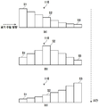
도시된 실시예는 대시보드 탭을 선택한 일 예가 도시된 도면으로, 도시된 바와 같이 대시보드 탭이 선택되면 환자의 상태, 압력 상태, 최대 압력에 대한 정보가 그래픽 정보로 출력될 수 있다. 구체적으로, 환자상태 영역에서는 환자의 어느 부위에 욕창이 발생했는지, 또는 어느 부위에 욕창이 발생할 우려가 있는지에 대한 정보를 신체 부위별로 표시할 수 있다. 또한, 압력상태 영역에서는 압력 센서(200)로부터 측정된 압력값을 머리, 허리, 다리 등과 같이 위치별로 구분하고, 각각의 위치에 대한 압력값을 게이지 바(gaugebar) 형태로 나타낼 수 있다. 그리고, 최대압력 영역에서는 수집된 압력값들 중 최대 압력값을 도출하여 게이지 바 형태로 나타낼 수 있다.The illustrated embodiment is a diagram showing an example in which a dashboard tab is selected, and when the dashboard tab is selected as shown, information about a patient's state, pressure state, and maximum pressure may be output as graphic information. Specifically, in the patient state area, information on which part of the patient has a pressure sore, or in which part there is a risk of pressure sores may be displayed for each body part. In addition, in the pressure state region, pressure values measured from the
또한, 사용자는 하단 UI에 배치된 타이머 모드 영역, 교대부양 on/off 영역을 선택하여 본 발명에 따른 욕창 방지용 매트리스(1)의 동작모드를 원격으로 제어할 수 있다. 예를 들어, 타이머 모드 영역을 선택하는 경우 욕창 방지용 매트리스(1)가 타이머 모드로 동작될 수 있으며, 교대부양 on/off 영역을 선택하는 경우 욕창 방지용 매트리스(1)는 수동 모드로 동작될 수 있다. 이와 관련된 구체적인 내용은 후술하기로 한다.In addition, the user can remotely control the operation mode of the
따라서, 사용자 단말을 이용하여 욕창 방지용 매트리스(1)를 관리하는 관리서버에 접속함으로써 사용자는 시간, 장소에 제약 없이 압력 게이지 바를 통해 실시간으로 환자의 상태를 확인하고 교대부양을 제어할 수 있다. Therefore, by connecting to the management server that manages the
한편, 본 발명의 일 실시예에 따른 제어 모듈(400)은 에어 셀의 교대부양 시간을 동적으로 변경할 수 있다. 이를 위해, 제어 모듈(400)은 제어 모듈(400)은 타이머 모드, 압력 모드 및 수동 모드 중 어느 하나의 모드로 동작될 수 있다. Meanwhile, the
일반적인 상황에서, 제어 모듈(400)은 타이머 모드가 활성화될 수 있다. 타이머 모드가 활성화되면, 제어 모듈(400)은 미리 정해진 시간 간격(예를 들어, 30분)으로 교대부양이 수행되도록 제어할 수 있다.In a general situation, the timer mode may be activated in the
또한, 제어 모듈(400)은 사용자 단말로부터 제어 신호를 수신하면 수동 모드가 활성화될 수 있다. 상술한 바와 같이, 사용자는 사용자 단말에 표시된 교대부양 on/off 영역을 선택하면, 사용자 단말은 이에 대한 제어신호(교대부양 on 제어신호 또는 교대부양 off 제어신호)를 생성하여 관리서버로 전송하고, 관리서버는 수신된 제어신호를 제어 모듈(400)로 전달할 수 있다. 제어 모듈(400)은 수신된 제어신호의 종류에 따라 교대부양의 수행 또는 정지를 제어하는 수동 모드로 동작될 수 있다.In addition, when the
한편, 제어 모듈(400)은 타이머 모드 또는 수동 모드로 동작하는 과정에서 압력 센서(200)로부터 수신되는 압력값을 분석하여 압력 모드를 자동으로 활성화할지 여부를 결정할 수 있다. 이와 관련하여, 도 4를 함께 참조하여 설명하기로 한다.Meanwhile, the
도 4는 제어 모듈(400)이 압력 모드의 활성화 여부를 결정하는 구체적인 흐름이 도시된 순서도이다.4 is a flowchart illustrating a specific flow in which the
먼저, 제어 모듈(400)은 통신 모듈(430)을 통해 복수의 압력 센서(200)로부터 복수의 압력값을 수신할 수 있다(41). 제어 모듈(400)은 수신된 압력값들의 평균 압력을 나타내는 평균값을 산출할 수 있다(42). 이때, 제어 모듈은 미리 정해진 소정 주기 간격으로 평균값을 산출할 수 있다.First, the
제어 모듈(400)은 소정 시간 동안 주기적으로 산출된 복수의 평균값을 비교하여 가장 큰 값을 나타내는 평균값을 최대 평균값으로 추출할 수 있다(43). 제어 모듈(400)은 추출된 최대 평균값을 미리 정해진 임계값과 비교할 수 있다(44).The
이때, 제어 모듈(400)은 최대 평균값이 임계값 이하인 것으로 확인되면(44의 NO), 기존에 활성화된 동작 모드를 유지시키고, 다시 압력값을 수신하는 단계(41)로 돌아가 상술한 과정을 반복하여 수행할 수 있다.At this time, if it is determined that the maximum average value is equal to or less than the threshold value (NO in 44), the
반면, 제어 모듈(400)은 최대 평균값이 임계값을 초과하는 것으로 확인되면(44의 YES), 최대 평균값의 크기에 따라 교대부양 시간을 동적으로 결정하는 압력 모드가 활성화될 수 있다(45). On the other hand, if it is determined that the maximum average value exceeds the threshold value (YES in 44), the
이 과정에서, 제어 모듈(400)은 압력 모드로 동작되는 구간 동안 최대 평균값의 크기가 커질수록 교대부양 주기가 단축되도록 제어할 수 있다. 예를 들어, 제어 모듈(400)은 3초 간격으로 평균값을 산출하고, 5분 동안 산출된 평균값들 중 가장 큰 값을 갖는 평균값을 최대 평균값으로 추출할 수 있다. 제어 모듈(400)은 추출된 최대 평균값을 미리 설정된 임계값과 비교하여, 최대 평균값이 임계값을 초과하면 압력 모드를 활성화시킬 수 있다. 이때, 제어 모듈(400)은 최대 평균값이 제1 크기값을 갖는 것으로 확인되면 교대부양 시간을 3분으로 설정할 수 있다. 그리고, 제어 모듈(400)은 3분 간격으로 교대부양을 수행하다가 5분 후에 다시 추출되는 최대 평균값을 확인하여, 추출된 최대 평균값이 제1 크기보다 큰 제2 크기를 갖는 것으로 확인되면, 교대부양 시간을 2분으로 설정할 수 있다. 이와 같이, 제어 모듈(400)은 추출된 최대 평균값의 크기에 따라 주기적으로 교대부양 시간을 동적으로 설정함으로써, 환자의 상태에 최적화된 교대부양을 수행할 수 있다.In this process, the
또한, 제어 모듈(400)은 최대 평균값이 미리 설정된 임계값 이하이면서, 소정 시간 동안 사용자 단말로부터 제어신호가 수신되지 않는 것으로 확인되면 압력 모드(또는 수동 모드)에서 타이머 모드로 동작 모드가 전환되도록 제어할 수 있다.In addition, the
몇몇 다른 실시예에서, 제어 모듈(400)은 좌우 방향뿐 아니라 전후 방향의 교대부양을 제어할 수 있다. 이하에서는, 설명의 편의를 위해 제1 에어 셀(110)과 제2 에어 셀(120)간의 교대부양을 좌우 방향의 교대부양으로 정의하여 설명하기로 한다.In some other embodiments, the
도 5는 전후 방향의 교대부양에 따른 제1 에어 셀의 단면도이다.5 is a cross-sectional view of the first air cell according to the alternate flotation in the front-rear direction.
도시된 바와 같이, 제어 모듈(400)은 공압 모터(300)의 출력을 제어하여 에어 셀에 주입되는 공기의 양을 조절함으로써, 어느 하나의 에어 셀에 대한 전후 방향의 교대부양을 제어할 수 있다. 예를 들어, 제어 모듈(400)은 제1 에어 셀(110)에 공기를 주입하는 좌우 방향의 교대부양 과정에서, 제1 공압 모터(310)의 출력을 최대 출력을 설정함으로써 순간적으로 주입되는 공기의 양을 급격하게 증가시킬 수 있다. 이러한 경우, 도 5의 (a)에 도시된 바와 같이 제1 에어 셀(110)의 입구 쪽에 순간적으로 많은 양의 공기가 주입되어 좌측에 위치한 부분 셀(S1)이 우측에 위치한 부분 셀들(S2, S3)보다 빠른 속도로 부양될 수 있다. 이후, 도 5의 (b) 및 (c)에 도시된 바와 같이, 주입된 공기는 시간이 흐름에 따라 제1 에어 셀(110)의 우측 방향으로 이동하면서 중간 부분에 위치한 부분 셀(S2)과 우측 부분에 위치한 부분 셀(S3)을 순차적으로 증가시킬 수 있다. As illustrated, the
반면, 제어 모듈(400)이 공압 모터(300)의 출력이 비교적 낮도록 제어하는 경우, 제1 에어 셀(110)은 모든 부분 셀의 높이가 동일한 속도로 상승되어 전후 방향의 교대부양이 수행되지 않도록 제어할 수도 있다. 이처럼, 제어 모듈(400)은 교대부양 시 상승하는 셀과 연결된 공압 모터의 출력을 제어함으로써 해당 에어 셀에 대한 전후 방향의 교대부양이 함께 수행되도록 제어할 수 있다.On the other hand, when the
도 2를 다시 참조하면, 이 외에도 제어 모듈(400)은 디스플레이 모듈(440) 및 알람 모듈(450)을 더 포함할 수 있다.Referring back to FIG. 2, in addition to this, the
디스플레이 모듈(440)은 본 발명에 따른 욕창 방지용 매트리스(1)의 동작 상태에 대한 정보를 시각적으로 나타낼 수 있다. The
알람 모듈(450)은 비상상황이 발생한 경우, 이를 환자 또는 주변 사람들에게 알릴 수 있다.The
일 예로, 알람 모듈(450)은 스피커를 포함할 수 있으며, 환자가 욕창 방지용 매트리스(1)의 일측에 구비된 비상 버튼을 누르거나, 사용자가 사용자 단말을 통해 비상 버튼에 해당되는 UI를 선택하면 스피커를 통해 소정 시간 동안 경고음이 울리도록 제어할 수 있다. For example, the
다른 예로, 알람 모듈(450)은 욕창 방지용 매트리스(1)가 압력 모드로 동작되는 것으로 확인되면 욕창 발생 위험이 높은 것으로 판단하여 환자, 간병인 또는 보호자가 소지한 사용자 단말로 전송할 문자 메시지를 생성할 수 있다. 따라서, 본 발명에 따른 욕창 방지용 매트리스(1)를 이용하는 경우 간병인이 환자 곁에 없는 경우에도 환자가 욕창 발생 위험이 높을 것으로 판단되는 상황에 대한 정보를 제공받을 수 있다.As another example, when it is confirmed that the
이상에서는 실시예들을 참조하여 설명하였지만, 해당 기술 분야의 숙련된 당업자는 하기의 특허 청구범위에 기재된 본 발명의 사상 및 영역으로부터 벗어나지 않는 범위 내에서 본 발명을 다양하게 수정 및 변경시킬 수 있음을 이해할 수 있을 것이다.Although described above with reference to embodiments, those skilled in the art understand that various modifications and changes can be made to the present invention without departing from the spirit and scope of the present invention as set forth in the claims below. Will be able to.
Claims (5)
상기 공압 매트리스에 가해지는 압력을 측정하여 압력값을 생성하는 적어도 하나의 압력 센서; 및
각각의 에어 셀과 연결된 공압 모터를 교번적으로 동작시켜 서로 이웃하는 에어 셀간의 교대부양을 제어하되, 상기 압력 센서로부터 수신되는 압력값에 따라 에어 셀의 교대부양 시간을 동적으로 변경하는 제어 모듈을 포함하며,
상기 제어 모듈은,
타이머 모드 및 수동 모드 중 어느 하나의 동작 모드를 활성화시키고,
서로 다른 위치에 배치된 상기 압력 센서로부터 수신되는 복수의 압력값의 평균값을 산출하고, 소정 시간 간격으로 산출된 복수의 평균값 중 최대 평균값이 미리 설정된 임계값을 초과하는 것으로 판단되면 상기 최대 평균값의 크기에 따라 교대부양 시간을 동적으로 결정하는 압력 모드가 활성화되고,
상기 최대 평균값이 상기 미리 설정된 임계값 이하인 것으로 판단되면, 기존에 활성화된 동작 모드를 유지시키고,
상기 압력 모드로 동작되는 구간 동안 상기 최대 평균값이 커질수록 교대부양 주기가 단축되도록, 공압 모터의 교번적인 동작 주기를 제어하는, 욕창 방지용 매트리스.
A pneumatic mattress consisting of at least two air cells;
At least one pressure sensor that generates a pressure value by measuring the pressure applied to the pneumatic mattress; And
A control module that alternately operates a pneumatic motor connected to each air cell to control the alternate flotation between adjacent air cells, but dynamically changes the alternate flotation time of the air cells according to the pressure value received from the pressure sensor. Includes,
The control module,
Activate either the timer mode or the manual mode,
The average value of the plurality of pressure values received from the pressure sensors arranged at different positions is calculated, and when it is determined that the maximum average value among the plurality of average values calculated at predetermined time intervals exceeds a preset threshold, the size of the maximum average value Depending on the pressure mode to dynamically determine the shift time is activated,
If it is determined that the maximum average value is equal to or less than the preset threshold, the previously activated operation mode is maintained,
During an operation period in the pressure mode, an alternating operation cycle of the pneumatic motor is controlled so that an alternate stimulation cycle is shortened as the maximum average value increases.
사용자 단말과 통신하는 통신 모듈을 더 포함하고,
상기 제어 모듈은, 상기 통신 모듈을 통해 상기 사용자 단말로부터 제어신호를 수신하면, 상기 제어신호에 따라 교대부양을 제어하는 상기 수동 모드가 활성화되는, 욕창 방지용 매트리스.
According to claim 1,
Further comprising a communication module for communicating with the user terminal,
The control module, when receiving a control signal from the user terminal through the communication module, the manual mode for controlling the alternate flotation according to the control signal is activated, mattress for preventing bedsores.
상기 제어 모듈은,
상기 최대 평균값이 미리 설정된 임계값 이하이면서, 소정 시간 동안 상기 제어신호가 수신되지 않는 것으로 확인되면 일정한 시간 간격으로 교대부양을 제어하는 상기 타이머 모드가 활성화되는, 욕창 방지용 매트리스.
The method of claim 4,
The control module,
When the maximum average value is equal to or less than a preset threshold value, and it is determined that the control signal is not received for a predetermined period of time, the timer mode for controlling the alternating levitation at regular time intervals is activated.
Priority Applications (1)
| Application Number | Priority Date | Filing Date | Title |
|---|---|---|---|
| KR1020180020370A KR102117746B1 (en) | 2018-02-21 | 2018-02-21 | Mattress for preventing pressure sore |
Applications Claiming Priority (1)
| Application Number | Priority Date | Filing Date | Title |
|---|---|---|---|
| KR1020180020370A KR102117746B1 (en) | 2018-02-21 | 2018-02-21 | Mattress for preventing pressure sore |
Publications (2)
| Publication Number | Publication Date |
|---|---|
| KR20190100606A KR20190100606A (en) | 2019-08-29 |
| KR102117746B1 true KR102117746B1 (en) | 2020-06-01 |
Family
ID=67776073
Family Applications (1)
| Application Number | Title | Priority Date | Filing Date |
|---|---|---|---|
| KR1020180020370A KR102117746B1 (en) | 2018-02-21 | 2018-02-21 | Mattress for preventing pressure sore |
Country Status (1)
| Country | Link |
|---|---|
| KR (1) | KR102117746B1 (en) |
Families Citing this family (8)
| Publication number | Priority date | Publication date | Assignee | Title |
|---|---|---|---|---|
| KR102305589B1 (en) * | 2019-11-15 | 2021-09-28 | 한국생산기술연구원 | Pressure split adjustable mattress |
| KR102351136B1 (en) * | 2019-11-18 | 2022-01-14 | 주식회사 더하일 | Embedded type bedsore prevention apparatus using body pressure characteristics of the user and bedsore prevention mat using the same |
| KR102359301B1 (en) * | 2020-02-28 | 2022-02-08 | 주식회사 에이치엠씨네트웍스 | A care system and method using wearable device |
| KR102546735B1 (en) * | 2020-08-07 | 2023-06-23 | 주식회사 알파메디아 | Bedsore prevention system |
| KR102595312B1 (en) * | 2020-11-18 | 2023-10-26 | 한남대학교 산학협력단 | Bed for preventing sore |
| KR102593307B1 (en) * | 2020-12-29 | 2023-10-26 | (주)에이블 디자인스 | Nursing robot system capable of position changing |
| US20230301863A1 (en) * | 2021-07-15 | 2023-09-28 | Halcyon Inc. | Mattress and control method thereof |
| KR102597481B1 (en) * | 2021-12-24 | 2023-11-03 | (주)에이블 디자인스 | Multi-Axis Responsive Caring Robot with Pressure Sore Prevention Monitoring |
Family Cites Families (5)
| Publication number | Priority date | Publication date | Assignee | Title |
|---|---|---|---|---|
| US9277829B2 (en) * | 2011-07-22 | 2016-03-08 | TC13—Pressure Applications LLC | Systems and methods for monitoring and providing therapeutic support for a user |
| KR101402377B1 (en) * | 2012-10-04 | 2014-06-03 | 주식회사 세라젬셀루피딕 | Mattress and method for controlling pressure of mattress |
| KR101810594B1 (en) | 2015-11-26 | 2018-01-25 | 울산대학교 산학협력단 | Mattress for patients to prevent a bedsore |
| KR20170135336A (en) * | 2016-05-31 | 2017-12-08 | 유도썬스(주) | Patient Management System and method for controlling the same |
| KR101798498B1 (en) | 2017-04-28 | 2017-11-16 | 주식회사 엠프로스 | Biometric information measuring device and system for sleep monitoring of infants |
-
2018
- 2018-02-21 KR KR1020180020370A patent/KR102117746B1/en active IP Right Grant
Also Published As
| Publication number | Publication date |
|---|---|
| KR20190100606A (en) | 2019-08-29 |
Similar Documents
| Publication | Publication Date | Title |
|---|---|---|
| KR102117746B1 (en) | Mattress for preventing pressure sore | |
| US8437876B2 (en) | Patient health based support apparatus configuration | |
| US7656299B2 (en) | Bed exit and patient detection system | |
| CN110123554A (en) | One kind is for the altricious pressure sore prevention air-sac mattress device of old man of lying in bed | |
| US7557718B2 (en) | Lack of patient movement monitor and method | |
| EP2772238B1 (en) | Sensors in a mattress cover | |
| JP6199135B2 (en) | Human body support device | |
| US20160317370A1 (en) | Cushion with bladders running different pressurization modes inside and outside dynamically selected target bladder group | |
| KR101935232B1 (en) | Bed for preventing fall | |
| KR102150031B1 (en) | Cushion for preventing bedsore that can be alternately lifted | |
| US11173818B1 (en) | Seat assembly | |
| WO2017032393A1 (en) | System and process for controlling the risks of appearance of pressure ulcers | |
| US20140304915A1 (en) | Occupant Support Adapted to Manage Pressure Ulcer Risk and Associated Risk Management Methods | |
| KR20180125175A (en) | Method for Controlling Artificial Intelligent Bedsore Preventing Mattress | |
| KR102546735B1 (en) | Bedsore prevention system | |
| JP4601275B2 (en) | Sleep bedding | |
| KR20100010365A (en) | Apparatus for preventing from sleeping respiratory obstruction and method using the same | |
| KR101731967B1 (en) | Bed for preventing decibitus | |
| CN204423593U (en) | Patient's alarming shift pad | |
| JP6047354B2 (en) | Mattress and control method thereof | |
| KR102519950B1 (en) | Medical bed | |
| KR100979308B1 (en) | Mattress for improvement a nose pendant and sleep apnea | |
| KR101094047B1 (en) | Mat for patient pulling and floating | |
| KR102449317B1 (en) | Mattress and its control method | |
| KR102692535B1 (en) | Bedsore preventing cushion for monitoring health and psychological status by measuring ballistocardiogram and method for operating the bedsore preventing cushion |
Legal Events
| Date | Code | Title | Description |
|---|---|---|---|
| A201 | Request for examination | ||
| E902 | Notification of reason for refusal | ||
| E902 | Notification of reason for refusal | ||
| E701 | Decision to grant or registration of patent right | ||
| GRNT | Written decision to grant |