KR101950846B1 - Light emitting diode display device - Google Patents
Light emitting diode display device Download PDFInfo
- Publication number
- KR101950846B1 KR101950846B1 KR1020120149852A KR20120149852A KR101950846B1 KR 101950846 B1 KR101950846 B1 KR 101950846B1 KR 1020120149852 A KR1020120149852 A KR 1020120149852A KR 20120149852 A KR20120149852 A KR 20120149852A KR 101950846 B1 KR101950846 B1 KR 101950846B1
- Authority
- KR
- South Korea
- Prior art keywords
- switching element
- power supply
- signal
- control signal
- maintained
- Prior art date
Links
Images


Classifications
-
- G—PHYSICS
- G09—EDUCATION; CRYPTOGRAPHY; DISPLAY; ADVERTISING; SEALS
- G09G—ARRANGEMENTS OR CIRCUITS FOR CONTROL OF INDICATING DEVICES USING STATIC MEANS TO PRESENT VARIABLE INFORMATION
- G09G3/00—Control arrangements or circuits, of interest only in connection with visual indicators other than cathode-ray tubes
- G09G3/20—Control arrangements or circuits, of interest only in connection with visual indicators other than cathode-ray tubes for presentation of an assembly of a number of characters, e.g. a page, by composing the assembly by combination of individual elements arranged in a matrix no fixed position being assigned to or needed to be assigned to the individual characters or partial characters
- G09G3/22—Control arrangements or circuits, of interest only in connection with visual indicators other than cathode-ray tubes for presentation of an assembly of a number of characters, e.g. a page, by composing the assembly by combination of individual elements arranged in a matrix no fixed position being assigned to or needed to be assigned to the individual characters or partial characters using controlled light sources
- G09G3/30—Control arrangements or circuits, of interest only in connection with visual indicators other than cathode-ray tubes for presentation of an assembly of a number of characters, e.g. a page, by composing the assembly by combination of individual elements arranged in a matrix no fixed position being assigned to or needed to be assigned to the individual characters or partial characters using controlled light sources using electroluminescent panels
- G09G3/32—Control arrangements or circuits, of interest only in connection with visual indicators other than cathode-ray tubes for presentation of an assembly of a number of characters, e.g. a page, by composing the assembly by combination of individual elements arranged in a matrix no fixed position being assigned to or needed to be assigned to the individual characters or partial characters using controlled light sources using electroluminescent panels semiconductive, e.g. using light-emitting diodes [LED]
- G09G3/3208—Control arrangements or circuits, of interest only in connection with visual indicators other than cathode-ray tubes for presentation of an assembly of a number of characters, e.g. a page, by composing the assembly by combination of individual elements arranged in a matrix no fixed position being assigned to or needed to be assigned to the individual characters or partial characters using controlled light sources using electroluminescent panels semiconductive, e.g. using light-emitting diodes [LED] organic, e.g. using organic light-emitting diodes [OLED]
- G09G3/3225—Control arrangements or circuits, of interest only in connection with visual indicators other than cathode-ray tubes for presentation of an assembly of a number of characters, e.g. a page, by composing the assembly by combination of individual elements arranged in a matrix no fixed position being assigned to or needed to be assigned to the individual characters or partial characters using controlled light sources using electroluminescent panels semiconductive, e.g. using light-emitting diodes [LED] organic, e.g. using organic light-emitting diodes [OLED] using an active matrix
- G09G3/3233—Control arrangements or circuits, of interest only in connection with visual indicators other than cathode-ray tubes for presentation of an assembly of a number of characters, e.g. a page, by composing the assembly by combination of individual elements arranged in a matrix no fixed position being assigned to or needed to be assigned to the individual characters or partial characters using controlled light sources using electroluminescent panels semiconductive, e.g. using light-emitting diodes [LED] organic, e.g. using organic light-emitting diodes [OLED] using an active matrix with pixel circuitry controlling the current through the light-emitting element
-
- G—PHYSICS
- G09—EDUCATION; CRYPTOGRAPHY; DISPLAY; ADVERTISING; SEALS
- G09G—ARRANGEMENTS OR CIRCUITS FOR CONTROL OF INDICATING DEVICES USING STATIC MEANS TO PRESENT VARIABLE INFORMATION
- G09G3/00—Control arrangements or circuits, of interest only in connection with visual indicators other than cathode-ray tubes
- G09G3/20—Control arrangements or circuits, of interest only in connection with visual indicators other than cathode-ray tubes for presentation of an assembly of a number of characters, e.g. a page, by composing the assembly by combination of individual elements arranged in a matrix no fixed position being assigned to or needed to be assigned to the individual characters or partial characters
- G09G3/22—Control arrangements or circuits, of interest only in connection with visual indicators other than cathode-ray tubes for presentation of an assembly of a number of characters, e.g. a page, by composing the assembly by combination of individual elements arranged in a matrix no fixed position being assigned to or needed to be assigned to the individual characters or partial characters using controlled light sources
- G09G3/30—Control arrangements or circuits, of interest only in connection with visual indicators other than cathode-ray tubes for presentation of an assembly of a number of characters, e.g. a page, by composing the assembly by combination of individual elements arranged in a matrix no fixed position being assigned to or needed to be assigned to the individual characters or partial characters using controlled light sources using electroluminescent panels
- G09G3/32—Control arrangements or circuits, of interest only in connection with visual indicators other than cathode-ray tubes for presentation of an assembly of a number of characters, e.g. a page, by composing the assembly by combination of individual elements arranged in a matrix no fixed position being assigned to or needed to be assigned to the individual characters or partial characters using controlled light sources using electroluminescent panels semiconductive, e.g. using light-emitting diodes [LED]
-
- G—PHYSICS
- G09—EDUCATION; CRYPTOGRAPHY; DISPLAY; ADVERTISING; SEALS
- G09G—ARRANGEMENTS OR CIRCUITS FOR CONTROL OF INDICATING DEVICES USING STATIC MEANS TO PRESENT VARIABLE INFORMATION
- G09G2300/00—Aspects of the constitution of display devices
- G09G2300/04—Structural and physical details of display devices
- G09G2300/0439—Pixel structures
- G09G2300/0465—Improved aperture ratio, e.g. by size reduction of the pixel circuit, e.g. for improving the pixel density or the maximum displayable luminance or brightness
-
- G—PHYSICS
- G09—EDUCATION; CRYPTOGRAPHY; DISPLAY; ADVERTISING; SEALS
- G09G—ARRANGEMENTS OR CIRCUITS FOR CONTROL OF INDICATING DEVICES USING STATIC MEANS TO PRESENT VARIABLE INFORMATION
- G09G2300/00—Aspects of the constitution of display devices
- G09G2300/08—Active matrix structure, i.e. with use of active elements, inclusive of non-linear two terminal elements, in the pixels together with light emitting or modulating elements
- G09G2300/0809—Several active elements per pixel in active matrix panels
- G09G2300/0814—Several active elements per pixel in active matrix panels used for selection purposes, e.g. logical AND for partial update
-
- G—PHYSICS
- G09—EDUCATION; CRYPTOGRAPHY; DISPLAY; ADVERTISING; SEALS
- G09G—ARRANGEMENTS OR CIRCUITS FOR CONTROL OF INDICATING DEVICES USING STATIC MEANS TO PRESENT VARIABLE INFORMATION
- G09G2300/00—Aspects of the constitution of display devices
- G09G2300/08—Active matrix structure, i.e. with use of active elements, inclusive of non-linear two terminal elements, in the pixels together with light emitting or modulating elements
- G09G2300/0809—Several active elements per pixel in active matrix panels
- G09G2300/0819—Several active elements per pixel in active matrix panels used for counteracting undesired variations, e.g. feedback or autozeroing
-
- G—PHYSICS
- G09—EDUCATION; CRYPTOGRAPHY; DISPLAY; ADVERTISING; SEALS
- G09G—ARRANGEMENTS OR CIRCUITS FOR CONTROL OF INDICATING DEVICES USING STATIC MEANS TO PRESENT VARIABLE INFORMATION
- G09G2300/00—Aspects of the constitution of display devices
- G09G2300/08—Active matrix structure, i.e. with use of active elements, inclusive of non-linear two terminal elements, in the pixels together with light emitting or modulating elements
- G09G2300/0809—Several active elements per pixel in active matrix panels
- G09G2300/0842—Several active elements per pixel in active matrix panels forming a memory circuit, e.g. a dynamic memory with one capacitor
- G09G2300/0861—Several active elements per pixel in active matrix panels forming a memory circuit, e.g. a dynamic memory with one capacitor with additional control of the display period without amending the charge stored in a pixel memory, e.g. by means of additional select electrodes
Landscapes
- Engineering & Computer Science (AREA)
- Physics & Mathematics (AREA)
- Computer Hardware Design (AREA)
- General Physics & Mathematics (AREA)
- Theoretical Computer Science (AREA)
- Control Of Indicators Other Than Cathode Ray Tubes (AREA)
- Control Of El Displays (AREA)
- Electroluminescent Light Sources (AREA)
Abstract
본 발명은 화소가 차지하는 면적을 줄여 고해상도 및 고정세의 표시패널 제조에 유리한 발광다이오드 표시장치에 관한 것으로, 제 1 스캔 스위칭소자, 제 1 전원전달 스위칭소자, 제 1 검출 스위칭소자, 제 1 구동 스위칭소자, 제 1 발광다이오드를 포함하는 제 1 화소와; 제 2 스캔 스위칭소자, 제 2 전원전달 스위칭소자, 제 2 검출 스위칭소자, 제 2 구동 스위칭소자, 제 2 발광다이오드를 포함하는 제 2 화소가 공통 커패시터를 공유한다. The present invention relates to a light emitting diode display device which is advantageous for manufacturing a display panel of a high resolution and a fixed size by reducing the area occupied by a pixel. The present invention relates to a light emitting diode display device having a first scan switching element, a first power supply switching element, a first detection switching element, A first pixel including a first light emitting diode; The second pixel including the second scan switching element, the second power supply switching element, the second detection switching element, the second drive switching element, and the second light emitting diode share a common capacitor.
Description
본 발명은 발광다이오드 표시장치에 관한 것으로, 특히 2개의 화소들이 하나의 공통 커패시터를 공유하도록 함으로써 화소가 차지하는 면적을 줄여 고해상도 및 고정세의 표시패널 제조에 유리한 발광다이오드 표시장치에 대한 것이다.The present invention relates to a light emitting diode display device, and more particularly, to a light emitting diode display device which is advantageous in manufacturing a high resolution and high definition display panel by reducing the area occupied by a pixel by allowing two pixels to share one common capacitor.
발광다이오드 표시장치의 화소들은 정전류 소자인 구동 스위칭소자를 포함한다. 이 구동스위칭소자들의 전류 구동능력은 이들의 문턱전압에 많은 영향을 받는다. 따라서, 화소별 구동 스위칭소자들간의 전류 구동능력 편차를 보정하는 것이 표시장치의 화질개선에 있어서 중요한 요소이다. 그런데, 이를 위해서는 하나의 화소에 많은 스위칭소자들 및 커패시터가 형성되어야 하는 바, 이로 인해 화소의 크기가 증가할 수밖에 없으며, 따라서 고해상도의 패널을 제작하는데 많은 제약이 따른다.The pixels of the light emitting diode display include a drive switching element which is a constant current element. The current drive capability of these drive switching elements is greatly affected by their threshold voltages. Therefore, it is an important factor in improving the picture quality of the display device to correct the current drivability deviation between the pixel-by-pixel driving switching elements. However, in order to accomplish this, a large number of switching elements and capacitors must be formed in one pixel, which results in an increase in the size of the pixel, and therefore, there are many restrictions in manufacturing a high-resolution panel.
본 발명은 상술된 문제점을 해결하기 위하여 안출된 것으로, 인접한 2개의 화소들이 하나의 커패시터(스토리지 커패시터)를 공유할 수 있도록 그 화소들의 회로 구조를 변경함으로써 화소의 크기를 상대적으로 줄일 수 있는 발광다이오드 표시장치를 제공하는데 그 목적이 있다.SUMMARY OF THE INVENTION The present invention has been made in order to solve the above-described problems, and it is an object of the present invention to provide a light emitting diode capable of relatively reducing the size of a pixel by changing a circuit structure of the pixels so that two adjacent pixels share one capacitor (storage capacitor) And a display device.
상술된 목적을 달성하기 위한 본 발명에 따른 발광다이오드 표시장치는, 제 1 스캔신호에 따라 제어되며, 데이터 라인과 제 1 노드 사이에 접속된 제 1 스캔 스위칭소자; 제 1 전원전달제어신호에 따라 제어되며, 제 1 구동전압을 전송하는 제 1 구동전원라인과 상기 제 1 노드 사이에 접속된 제 1 전원전달 스위칭소자; 제 1 문턱전압검출신호에 따라 제어되며, 제 2 노드와 제 3 노드 사이에 접속된 제 1 검출 스위칭소자; 상기 제 2 노드에 인가된 신호에 따라 제어되며, 상기 제 1 구동전원라인과 상기 제 3 노드 사이에 접속된 제 1 구동 스위칭소자; 제 1 발광제어신호에 따라 제어되며, 상기 제 3 노드와 제 1 발광다이오드 사이에 접속된 제 1 발광제어 스위칭소자; 제 2 스캔신호에 따라 제어되며, 데이터 라인과 상기 제 2 노드 사이에 접속된 제 2 스캔 스위칭소자; 제 2 전원전달제어신호에 따라 제어되며, 상기 제 1 구동전원라인과 상기 제 2 노드 사이에 접속된 제 2 전원전달 스위칭소자; 제 2 문턱전압검출신호에 따라 제어되며, 상기 제 1 노드와 제 4 노드 사이에 접속된 제 2 검출 스위칭소자; 상기 제 2 노드에 인가된 신호에 따라 제어되며, 상기 제 1 구동전원라인과 상기 제 3 노드 사이에 접속된 제 2 구동 스위칭소자; 제 2 발광제어신호에 따라 제어되며, 상기 제 4 노드와 제 2 발광다이오드 사이에 접속된 제 2 발광제어 스위칭소자; 및, 상기 제 1 노드와 제 2 노드 사이에 접속된 공통 커패시터를 포함함을 특징으로 한다.According to an aspect of the present invention, there is provided a light emitting diode display comprising: a first scan switching element controlled according to a first scan signal and connected between a data line and a first node; A first power supply switching element controlled in response to a first power supply control signal and connected between a first driving power supply line for transmitting a first driving voltage and the first node; A first detection switching element controlled in accordance with a first threshold voltage detection signal and connected between a second node and a third node; A first driving switching element controlled according to a signal applied to the second node, the first driving switching element being connected between the first driving power supply line and the third node; A first emission control switching element controlled according to a first emission control signal and connected between the third node and the first light emitting diode; A second scan switching element controlled according to a second scan signal and connected between the data line and the second node; A second power supply switching element controlled in response to a second power supply control signal, the second power supply switching element being connected between the first driving power supply line and the second node; A second detection switching element controlled in accordance with a second threshold voltage detection signal, the second detection switching element being connected between the first node and the fourth node; A second driving switching element controlled according to a signal applied to the second node, the second driving switching element being connected between the first driving power supply line and the third node; A second emission control switching element controlled according to a second emission control signal and connected between the fourth node and the second light emitting diode; And a common capacitor connected between the first node and the second node.
상기 제 1 스캔 스위칭소자, 제 1 전원전달 스위칭소자, 제 1 검출 스위칭소자, 제 1 구동 스위칭소자, 제 1 발광다이오드가 제 1 화소에 포함되며; 상기 제 2 스캔 스위칭소자, 제 2 전원전달 스위칭소자, 제 2 검출 스위칭소자, 제 2 구동 스위칭소자 및 제 2 발광다이오드가 제 2 화소에 포함되며; 상기 제 1 화소와 제 2 화소가 상기 공통 커패시터를 공유함을 특징으로 한다.Wherein the first scan switching element, the first power supply switching element, the first detection switching element, the first drive switching element, and the first light emitting diode are included in the first pixel; The second scan switching element, the second power supply switching element, the second detection switching element, the second driving switching element, and the second light emitting diode are included in the second pixel; And the first pixel and the second pixel share the common capacitor.
상기 제 1 화소와 제 2 화소가 번갈아가며 상기 공통 커패시터를 이용함을 특징으로 한다.The first pixel and the second pixel alternate with each other and use the common capacitor.
상기 제 1 화소는 한 프레임의 전반부에 제 1 발광다이오드를 점등시키고, 제 2 화소는 상기 한 프레임의 후반부에 제 2 발광다이오드를 점등시키며; 제 1 및 제 2 발광다이오드들 중 어느 하나가 점등될 때, 나머지 하나의 발광다이오드는 소등된 상태인 것을 특징으로 한다.The first pixel lights up the first light emitting diode in the first half of one frame and the second pixel lights the second light emitting diode in the second half of the one frame; When one of the first and second light emitting diodes is turned on, the other one of the light emitting diodes is off.
상기 제 1 및 제 2 화소는 리셋기간, 프로그래밍기간 및 발광기간의 순서로 구동되며; 상기 전반부의 리셋기간 동안, 상기 제 1 스캔신호가 비액티브 상태로 유지되고, 상기 제 1 전원전달제어신호가 액티브 상태로 유지되고, 상기 제 1 문턱전압검출신호가 비액티브 상태로 유지되고, 상기 제 1 발광제어신호가 비액티브 상태로 유지되고, 상기 제 2 스캔신호가 액티브 상태로 유지되고, 제 2 전원전달제어신호가 비액티브 상태로 유지되고, 제 2 문턱전압검출신호가 비액티브 상태로 유지되고, 제 2 발광제어신호가 비액티브 상태로 유지되고, 그리고 상기 데이터 라인으로 기준전압이 인가되며; 상기 전반부의 프로그래밍기간 동안, 상기 제 1 스캔신호가 액티브 상태로 유지되고, 상기 제 1 전원전달제어신호가 비액티브 상태로 유지되고, 상기 제 1 문턱전압검출신호가 액티브 상태로 유지되고, 상기 제 1 발광제어신호가 비액티브 상태로 유지되고, 상기 제 2 스캔신호가 비액티브 상태로 유지되고, 제 2 전원전달제어신호가 비액티브 상태로 유지되고, 제 2 문턱전압검출신호가 비액티브 상태로 유지되고, 제 2 발광제어신호가 비액티브 상태로 유지되고, 그리고 상기 데이터 라인으로 상기 제 1 화소에 해당하는 제 1 데이터전압이 인가되며; 그리고, 상기 전반부의 발광기간 동안, 상기 제 1 스캔신호가 비액티브 상태로 유지되고, 상기 제 1 전원전달제어신호가 액티브 상태로 유지되고, 상기 제 1 문턱전압검출신호가 비액티브 상태로 유지되고, 상기 제 1 발광제어신호가 액티브 상태로 유지되고, 상기 제 2 스캔신호가 비액티브 상태로 유지되고, 제 2 전원전달제어신호가 비액티브 상태로 유지되고, 제 2 문턱전압검출신호가 비액티브 상태로 유지되고, 그리고 제 2 발광제어신호가 비액티브 상태로 유지됨을 특징으로 한다.Wherein the first and second pixels are driven in the order of a reset period, a programming period, and a light emitting period; During the reset period of the first half, the first scan signal is maintained in an inactive state, the first power supply control signal is maintained in an active state, the first threshold voltage detection signal is maintained in an inactive state, The first emission control signal is maintained in the inactive state, the second scan signal is maintained in the active state, the second power supply transfer control signal is maintained in the inactive state, and the second threshold voltage detection signal is in the inactive state The second emission control signal is kept inactive, and a reference voltage is applied to the data line; During the programming period of the first half, the first scan signal is maintained in an active state, the first power supply control signal is kept inactive, the first threshold voltage detection signal is maintained in an active state, 1 emission control signal remains inactive, the second scan signal remains inactive, the second power supply transfer control signal remains inactive, and the second threshold voltage detection signal becomes inactive The second emission control signal is kept inactive, and a first data voltage corresponding to the first pixel is applied to the data line; During the light emission period of the first half, the first scan signal is maintained in an inactive state, the first power supply control signal is maintained in an active state, the first threshold voltage detection signal is maintained in an inactive state , The first emission control signal is maintained in the active state, the second scan signal is maintained in the inactive state, the second power supply control signal is maintained in the inactive state, the second threshold voltage detection signal is inactive State, and the second emission control signal is maintained in an inactive state.
상기 후반부의 리셋기간 동안, 상기 제 2 스캔신호가 비액티브 상태로 유지되고, 상기 제 2 전원전달제어신호가 액티브 상태로 유지되고, 상기 제 2 문턱전압검출신호가 비액티브 상태로 유지되고, 상기 제 2 발광제어신호가 비액티브 상태로 유지되고, 상기 제 1 스캔신호가 액티브 상태로 유지되고, 제 1 전원전달제어신호가 비액티브 상태로 유지되고, 제 1 문턱전압검출신호가 비액티브 상태로 유지되고, 제 1 발광제어신호가 비액티브 상태로 유지되고, 그리고 상기 데이터 라인으로 기준전압이 인가되며; 상기 후반부의 프로그래밍기간 동안, 상기 제 2 스캔신호가 액티브 상태로 유지되고, 상기 제 2 전원전달제어신호가 비액티브 상태로 유지되고, 상기 제 2 문턱전압검출신호가 액티브 상태로 유지되고, 상기 제 2 발광제어신호가 비액티브 상태로 유지되고, 상기 제 1 스캔신호가 비액티브 상태로 유지되고, 제 1 전원전달제어신호가 비액티브 상태로 유지되고, 제 1 문턱전압검출신호가 비액티브 상태로 유지되고, 제 1 발광제어신호가 비액티브 상태로 유지되고, 그리고 상기 데이터 라인으로 상기 제 2 화소에 해당하는 제 2 데이터전압이 인가되며; 그리고, 상기 후반부의 발광기간 동안, 상기 제 2 스캔신호가 비액티브 상태로 유지되고, 상기 제 2 전원전달제어신호가 액티브 상태로 유지되고, 상기 제 2 문턱전압검출신호가 비액티브 상태로 유지되고, 상기 제 2 발광제어신호가 액티브 상태로 유지되고, 상기 제 1 스캔신호가 비액티브 상태로 유지되고, 제 1 전원전달제어신호가 비액티브 상태로 유지되고, 제 1 문턱전압검출신호가 비액티브 상태로 유지되고, 그리고 제 1 발광제어신호가 비액티브 상태로 유지됨을 특징으로 한다.The second scan signal is maintained in an inactive state, the second power supply control signal is maintained in an active state, the second threshold voltage detection signal is maintained in an inactive state during the second half of the reset period, The first emission control signal is maintained in the inactive state, the first scan signal is kept in the active state, the first power supply control signal is maintained in the inactive state, and the first threshold voltage detection signal is in the inactive state The first emission control signal is kept inactive, and a reference voltage is applied to the data line; During the programming period of the second half, the second scan signal is kept in an active state, the second power supply control signal is maintained in an inactive state, the second threshold voltage detection signal is kept in an active state, 2 emission control signal is kept inactive, the first scan signal is kept inactive, the first power supply control signal is kept inactive, and the first threshold voltage detection signal is inactive The first emission control signal is kept inactive, and a second data voltage corresponding to the second pixel is applied to the data line; During the second half of the light emission period, the second scan signal is maintained in the inactive state, the second power supply control signal is maintained in the active state, the second threshold voltage detection signal is maintained in the inactive state , The second emission control signal is maintained in an active state, the first scan signal is maintained in an inactive state, the first power supply control signal is maintained in an inactive state, and the first threshold voltage detection signal is inactive State, and the first emission control signal is maintained in the inactive state.
본 발명에서는 2개의 화소들 당 하나의 공통 커패시터만이 필요하므로, 화소의 크기가 작아질 수 있다. 따라서, 본 발명에서의 화소 구조를 이용할 경우 고해상도 및 고정세의 패널을 제작하는데 유리하다.In the present invention, since only one common capacitor is required per two pixels, the size of the pixel can be reduced. Therefore, when the pixel structure of the present invention is used, it is advantageous to manufacture a panel of high resolution and high definition.
도 1은 본 발명의 실시예에 따른 발광다이오드 표시장치를 나타낸 도면
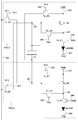
도 2는 본 발명의 실시예에 따른 화소의 회로 구성을 나타낸 도면
도 3a는 전반부 기간 동안에서의 제 1 화소로 인가되는 제어신호들 및 제 2 화소로 인가되는 제어신호들의 파형을 나타낸 도면
도 3b는 후반부 기간 동안에서의 제 1 화소로 인가되는 제어신호들 및 제 2 화소로 인가되는 제어신호들의 파형을 나타낸 도면
도 4a 내지 도 4c는 도 2에서의 각 기간별 화소의 회로 상태를 나타낸 도면
도 5a 및 도 5b는 동일한 데이터라인에 연결되며 서로 다른 홀수 번째 수평라인에 위치한 2개 화소들로 공급되는 제어신호들의 타이밍을 설명하기 위한 도면
도 6은 본 발명의 실시예에 따른 화소의 회로의 또 다른 구성을 나타낸 도면
도 7은 전반부 기간 및 후반부 기간에서의 발광다이오드에 흐르는 전류 및 공통 커패시터의 양단에 걸린 전압을 나타낸 도면
도 8은 구동 스위칭소자의 문턱전압 변화량에 따른 구동전류의 변화량을 나타낸 도면
도 9는 본 발명의 효과를 설명하기 위한 도면1 is a view illustrating a light emitting diode display device according to an embodiment of the present invention.
2 is a diagram showing a circuit configuration of a pixel according to an embodiment of the present invention;
3A shows waveforms of control signals applied to a first pixel and control signals applied to a second pixel during a first half period;
3B is a view showing waveforms of control signals applied to the first pixel and control signals applied to the second pixel during the second half period;
Figs. 4A to 4C are diagrams showing circuit states of pixels in each period in Fig. 2
5A and 5B are diagrams for explaining the timing of control signals supplied to two pixels connected to the same data line and located on different odd-numbered horizontal lines
6 is a diagram showing another configuration of a circuit of a pixel according to the embodiment of the present invention
7 is a graph showing the current flowing in the light emitting diode and the voltage across the common capacitor in the first half period and the second half period
8 is a graph showing the amount of change in the driving current according to the amount of change in the threshold voltage of the driving switching element
9 is a view for explaining the effect of the present invention
도 1은 본 발명의 실시예에 따른 발광다이오드 표시장치를 나타낸 도면이다.1 is a view illustrating a light emitting diode display device according to an embodiment of the present invention.
본 발명의 실시예에 따른 발광다이오드 표시장치는, 도 1에 도시된 바와 같이, 표시부(DSP), 시스템(SYS), 게이트 드라이버(GD), 데이터 드라이버(DD) 및 타이밍 컨트롤러(TC)를 포함한다.1, a light emitting diode display device according to an embodiment of the present invention includes a display unit (DSP), a system SYS, a gate driver GD, a data driver DD, and a timing controller TC do.
표시부(DSP)는 다수의 화소(PXL)들과, i개(i는 1보다 큰 자연수)의 스캔라인들(SL1 내지 SLi)과, 그리고 j개(j는 1보다 큰 자연수)의 데이터 라인들(DL1 내지 DLj)을 포함한다. The display unit DSP includes a plurality of pixels PXL, i (i is a natural number greater than 1) scan lines SL1 to SLi, and j (j is a natural number greater than 1) (DL1 to DLj).
이 화소(PXL)들은 매트릭스 형태로 표시부(DSP)에 배열되어 있다. 이 화소(PXL)들은 적색을 표시하는 적색 화소(PXL), 녹색을 표시하는 녹색 화소(PXL) 및 청색을 표시하는 청색 화소(PXL)로 구분된다. 이때, 수평 방향으로 인접한 적색 화소, 녹색 화소 및 청색 화소는 하나의 단위 영상을 표시하기 위한 단위 화소가 된다. These pixels PXL are arranged in a matrix on the display unit DSP. The pixels PXL are divided into a red pixel PXL for displaying red, a green pixel PXL for displaying green, and a blue pixel PXL for displaying blue. At this time, the red pixels, green pixels and blue pixels adjacent in the horizontal direction are unit pixels for displaying one unit image.
한편, 도 1에 도시되지 않았지만, 이 표시부(DSP)에는 제 1 구동전원라인, 제 2 구동전원라인, i개의 전달스위치제어라인들, i개의 검출스위치제어라인들, i개의 발광스위치제어라인들이 더 형성된다.Although not shown in FIG. 1, the display unit DSP includes a first driving power supply line, a second driving power supply line, i transfer switch control lines, i detection switch control lines, i light emission switch control lines Lt; / RTI >
즉, 이 표시부에는, 제 1 구동전원라인, 제 2 구동전원라인, 제 1 내지 제 i 스캔라인들, 제 1 내지 제 i 전달스위치제어라인들, 제 1 내지 제 i 검출스위치제어라인들, 그리고 제 1 내지 제 i 발광스위치제어라인들이 형성된다.That is, the display unit is provided with a first driving power supply line, a second driving power supply line, first through i-th scan lines, first through i-th transfer switch control lines, first through i-th detection switch control lines, The first to i-th emission switch control lines are formed.
제 1 구동전원라인으로는 제 1 구동전압이 인가되며, 제 2 구동전원라인으로는 제 2 구동전압이 인가되며, 제 1 내지 제 i 스캔라인들로는 각각 제 1 내지 제 i 스캔신호가 인가되며, 제 1 내지 제 i 전달스위치제어라인들로는 각각 제 1 내지 제 i 전원전달제어신호들이 인가되며, 제 1 내지 제 i 검출스위치제어라인들로는 각각 제 1 내지 제 i 문턱전압검출신호들이 인가되며, 그리고 제 1 내지 제 i 발광스위치제어라인들로는 각각 제 1 내지 제 i 문턱전압검출신호들이 인가된다. A first driving voltage is applied to the first driving power supply line, a second driving voltage is applied to the second driving power supply line, first through i-th scan signals are applied to the first through i-th scan lines, The first through i-th transfer switch control lines receive first through i-th power supply control signals, first through i-th switch control lines receive first through i-th threshold voltage detection signals, respectively, 1 th to i < th > emission switch control lines are respectively applied with first to i-th threshold voltage detection signals.
제 k 수평라인(k는 1 내지 i 중 어느 하나)을 따라 배열된 화소들(이하, k번째 수평라인 화소들)은 제 1 구동전원라인, 제 2 구동전원라인, 제 k 전달스위치제어라인, 제 k 검출스위치제어라인, 제 k 구동스위치제어라인, 제 k 발광스위치제어라인, 제 k 전달스위치제어라인 및 제 k 검출스위치제어라인에 공통으로 접속된다.The pixels (hereinafter, kth horizontal line pixels) arranged along the kth horizontal line (k is any one of 1 to i) are connected to the first driving power supply line, the second driving power supply line, the kth transfer switch control line, The kth detection switch control line, the kth drive switch control line, the kth emission switch control line, the kth transfer switch control line, and the kth detection switch control line.
동일 데이터 라인에 접속된 화소들 중 제 k 수평라인의 화소와 이에 대응되는 제 k+1 수평라인의 화소는 공통 커패시터(CC)에 공통으로 접속된다. 예를 들어, 제 1 데이터 라인(DL1)에 접속되며 제 1 수평라인(HL1)에 위치한 적색 화소(R)와, 이 제 1 데이터 라인(DL1)에 접속되며 제 2 수평라인(HL2)에 위치한 적색 화소(R)는 공통 커패시터(CC)에 공통으로 접속된다.The pixels of the kth horizontal line and the pixel of the (k + 1) th horizontal line corresponding to the pixels connected to the same data line are commonly connected to the common capacitor CC. For example, the red pixel R connected to the first data line DL1 and located at the first horizontal line HL1, the red pixel R connected to the first data line DL1 and the second horizontal line HL2, And the red pixel R is commonly connected to the common capacitor CC.
한 프레임의 전반부(즉, 전반 1/2 프레임) 기간 동안에는, 공통 커패시터(CC)를 기준으로 그 위에 위치한 홀수 번째 수평라인(HL1, HL3, HL3, ...)의 화소들이 이 공통 커패시터(CC)를 사용한다. 반면, 그 한 프레임의 후반부(즉, 후반 1/2 프레임) 기간 동안에는 그 공통 커패시터(CC)를 기준으로 그 아래에 위치한 짝수 번째 수평라인(HL2, HL4, HL5, ...)의 화소들이 그 공통 커패시터(CC)를 사용한다.The pixels of the odd-numbered horizontal lines HL1, HL3, HL3, ... located above the common capacitor CC are connected to the common capacitor CC ) Is used. On the other hand, the pixels of the even-numbered horizontal lines (HL2, HL4, HL5, ...) located beneath the common capacitor CC during the latter half of the frame A common capacitor (CC) is used.
전반부 기간 동안, 홀수 번째 수평라인의 화소들이 수평라인 단위로 순차적으로 구동된다. 이후, 후반부 기간 동안, 짝수 번째 수평라인의 화소들이 수평라인 단위로 순차적으로 구동된다. 예를 들어, 전반부 기간 동안, 제 1 수평라인(HL1)의 화소들, 제 3 수평라인(HL3)의 화소들, 제 5 수평라인(HL5)의 화소들, ..., 제 i-1 수평라인의 화소들이 수평라인 단위로 순차적으로 구동된다. 그 후, 후반부 기간 동안, 제 2 수평라인(HL2)의 화소들, 제 4 수평라인(HL4)들의 화소들, 제 6 수평라인(HL6)의 화소들, ..., 제 i 수평라인(HLi)의 화소들이 수평라인 단위로 순차적으로 구동된다.During the first half period, the pixels of the odd-numbered horizontal lines are sequentially driven in units of horizontal lines. Then, during the second half period, the pixels of the even-numbered horizontal lines are sequentially driven in units of horizontal lines. For example, during the first half period, the pixels of the first horizontal line HL1, the pixels of the third horizontal line HL3, the pixels of the fifth horizontal line HL5, The pixels of the line are sequentially driven in units of horizontal lines. Then, during the second half period, the pixels of the second horizontal line HL2, the pixels of the fourth horizontal line HL4, the pixels of the sixth horizontal line HL6, ..., the i-th horizontal line HLi Are successively driven in units of horizontal lines.
동일 수평라인의 화소들로 공급되는 스캔신호, 전원전달제어신호, 문턱전압검출신호 및 발광제어신호는, 전반부 기간 및 후반부 기간별로 그 신호의 상태가 달라진다. 즉, 전반부 기간에 제 k 수평라인의 화소들로 공급되는 제 k 스캔신호, 제 k 전원전달제어신호, 제 k 문턱전압검출신호 및 제 k 발광제어신호는, 후반부 기간에 상기 제 k 수평라인의 화소들로 공급되는 제 k 스캔신호, 제 k 전원전달제어신호, 제 k 문턱전압검출신호 및 제 k 발광제어신호와 다른 상태가 된다. The scan signal, the power supply transfer control signal, the threshold voltage detection signal, and the emission control signal supplied to the pixels on the same horizontal line have different states in the first half period and the second half period. That is, the k th scan signal, the k th power supply control signal, the k th threshold voltage detection signal, and the k th emission control signal, which are supplied to the pixels of the k th horizontal line in the first half period, The k th scan signal, the k th power supply control signal, the k th threshold voltage detection signal, and the k th emission control signal supplied to the pixels.
또한, 동일 기간에 홀수 번째 수평라인들의 화소들로 공급되는 스캔신호들, 전원전달제어신호들, 문턱전압검출신호들 및 발광제어신호들은, 짝수 번째 수평라인들의 화소들로 공급되는 스캔신호들, 전원전달제어신호들, 문턱전압검출신호들 및 발광제어신호들과 다른 상태를 갖는다. 즉, 전반부 기간에 제 2k-1 수평라인의 화소들로 인가되는 제 2k-1 스캔신호, 제 2k-1 전원전달제어신호, 제 2k-1 문턱전압검출신호 및 제 2k-1 발광제어신호는, 그 전반부 기간에 제 2k 수평라인의 화소들로 인가되는 제 2k 스캔신호, 제 2k 전원전달제어신호, 제 2k 문턱전압검출신호 및 제 2k 발광제어신호와 다른 형태를 갖는다.In addition, the scan signals, power supply control signals, threshold voltage detection signals, and emission control signals supplied to the pixels of the odd-numbered horizontal lines in the same period are supplied to the pixels of the even- Power supply control signals, threshold voltage detection signals, and emission control signals. The second k-1 scan signal, the second k-1 power supply control signal, the (2k-1) th threshold voltage detection signal, and the (2k-1) th emission control signal applied to the pixels of the (2k- The second k power supply control signal, the second k th threshold voltage detection signal, and the second k emission control signal applied to the pixels of the second k horizontal line in the first half period.
한편, 전반부 기간 동안, 홀수 번째 수평라인들 공급되는 i/2개의 스캔신호들, i/2개의 전원전달제어신호들, i/2개의 문턱전압검출신호 및 i/2개의 발광제어신호들은, 동일 이름의 신호들끼리 실상 동일한 형태이며 단지 시간적으로 출력 타이밍만 다를 뿐이다. 예를 들어, 전반부 기간 동안, 제 1 수평라인(HL1)에 공급되는 제 1 스캔신호와 제 3 수평라인(HL1)에 공급되는 제 3 스캔신호는 사실상 동일한 형태이며, 단지 제 3 스캔신호가 제 1 스캔신호에 비하여 일정 시간만큼 지연되어 출력될 뿐이다. 제 1 스캔신호를 기준으로 할 때, 더 큰 번호를 부여받은 스캔신호일수록 이 제 1 스캔신호로부터 더 지연되어 출력된다. 즉, 제 5 스캔신호는 제 3 스캔신호보다 더 지연되어 출력된다.On the other hand, during the first half period, i / 2 scan signals, i / 2 power supply control signals, i / 2 threshold voltage detection signals and i / 2 emission control signals supplied to odd- The signals of the name are actually the same type and only the output timing is different in time. For example, during the first half period, the first scan signal supplied to the first horizontal line HL1 and the third scan signal supplied to the third horizontal line HL1 are substantially the same type, and only the
마찬가지로, 후반부 기간 동안, 홀수 번째 수평라인들 공급되는 i/2개의 스캔신호들, i/2개의 전원전달제어신호들, i/2개의 문턱전압검출신호 및 i/2개의 발광제어신호들은, 동일 이름의 신호들끼리 실상 동일한 형태이며 단지 시간적으로 출력 타이밍만 다를 뿐이다.Similarly, during the latter half period, i / 2 scan signals, i / 2 power supply control signals, i / 2 threshold voltage detection signals and i / 2 emission control signals supplied to odd- The signals of the name are actually the same type and only the output timing is different in time.
같은 방식으로, 전반부 기간 동안, 짝수 번째 수평라인들 공급되는 i/2개의 스캔신호들, i/2개의 전원전달제어신호들, i/2개의 문턱전압검출신호 및 i/2개의 발광제어신호들은, 동일 이름의 신호들끼리 실상 동일한 형태이며 단지 시간적으로 출력 타이밍만 다를 뿐이다.In the same manner, i / 2 scan signals, i / 2 power supply control signals, i / 2 threshold voltage detection signals and i / 2 emission control signals supplied to even- , Signals of the same name are actually the same type, and only the output timing is different in time.
역시, 후반부 기간 동안, 짝수 번째 수평라인들 공급되는 i/2개의 스캔신호들, i/2개의 전원전달제어신호들, i/2개의 문턱전압검출신호 및 i/2개의 발광제어신호들은, 동일 이름의 신호들끼리 실상 동일한 형태이며 단지 시간적으로 출력 타이밍만 다를 뿐이다.During the latter half of the same period, i / 2 scan signals, i / 2 power supply control signals, i / 2 threshold voltage detection signals, and i / 2 emission control signals supplied to even- The signals of the name are actually the same type and only the output timing is different in time.
시스템(SYS)은 그래픽 콘트롤러의 LVDS(Low Voltage Differential Signaling) 송신기를 통하여 수직동기신호, 수평 동기신호, 클럭신호 및 영상 데이터들을 인터페이스회로를 통해 출력한다. 이 시스템(SYS)으로부터 출력된 수직/수평 동기신호 및 클럭신호는 타이밍 컨트롤러(TC)에 공급된다. 또한, 이 시스템(SYS)으로부터 순차적으로 출력된 영상 데이터들은 타이밍 컨트롤러(TC)에 공급된다.The system SYS outputs a vertical synchronizing signal, a horizontal synchronizing signal, a clock signal, and image data through an interface circuit through a Low Voltage Differential Signaling (LVDS) transmitter of a graphic controller. The vertical / horizontal synchronizing signal and the clock signal output from the system SYS are supplied to the timing controller TC. In addition, the image data sequentially output from the system SYS is supplied to the timing controller TC.
타이밍 컨트롤러(TC)는 자신에게 입력되는 수평동기신호, 수직동기신호, 및 클럭신호를 이용하여 데이터제어신호 및 게이트제어신호를 발생시켜 데이터 드라이버(DD) 및 게이트 드라이버(GD)로 공급한다. The timing controller TC generates a data control signal and a gate control signal using a horizontal synchronizing signal, a vertical synchronizing signal, and a clock signal input to the timing controller TC, and supplies the data control signal and the gate control signal to the data driver DD and the gate driver GD.
데이터 드라이버(DD)는 타이밍 컨트롤러(TC)로부터의 데이터제어신호에 따라 영상 데이터들을 샘플링한 후에, 매 수평기간(Horizontal Time : 1H, 2H, ...)마다 한 수평라인분에 해당하는 샘플링 영상 데이터들을 래치하고 래치된 영상 데이터들을 데이터라인들(DL1 내지 DLj)에 공급한다. 즉, 데이터 드라이버(DD)는 타이밍 컨트롤러(TC)로부터의 영상 데이터를 전원공급부(도시되지 않음)로부터 입력되는 감마전압을 이용하여 아날로그 데이터신호로 변환하여 데이터라인들(DL1 내지 DLj)로 공급한다. 또한, 이 데이터 드라이버는 기준전압을 출력하여 데이터 라인들로 공급한다. 이 기준전압은 0[V]가 될 수 있다. 한편, 데이터신호는 데이터전압에 제 1 구동전압이 합쳐진 전압이다.The data driver DD samples the image data according to the data control signal from the timing controller TC and then outputs the sampling image corresponding to one horizontal line per horizontal period (1H, 2H, ...) Latches the data and supplies the latched image data to the data lines DL1 to DLj. That is, the data driver DD converts the image data from the timing controller TC into an analog data signal using a gamma voltage input from a power supply unit (not shown) and supplies the analog data signal to the data lines DL1 to DLj . In addition, the data driver outputs a reference voltage and supplies it to the data lines. This reference voltage can be 0 [V]. On the other hand, the data signal is the sum of the data voltage and the first driving voltage.
게이트 드라이버(GD)는 타이밍 컨트롤러(TC)로부터의 게이트제어신호에 따라 전술된 제 1 내지 제 i 스캔신호들, 제 1 내지 제 i 전원전달제어신호들, 제 1 내지 제 i 문턱전압검출신호들, 그리고 제 1 내지 제 i 발광제어신호들을 생성하여 화소들로 출력한다. 이 제 1 내지 제 i 스캔신호들, 제 1 내지 제 i 전원전달제어신호들, 제 1 내지 제 i 문턱전압검출신호들, 그리고 제 1 내지 제 i 발광제어신호들은 액티브 상태(로우레벨 전압)일 때 -10[V]를 가지며, 비액티브 상태(하이레벨 전압)일 때 14[V]의 전압을 가질 수 있다.The gate driver GD outputs the first to i-th scan signals, first to i-th power supply transfer control signals, first to i-th threshold voltage detection signals And the first to i-th emission control signals, and outputs the generated signals to the pixels. The first through i-th scan signals, first through i-th power supply control signals, first through i-th threshold voltage detection signals, and first through i-th emission control signals are in an active state And has a voltage of 14 [V] when it is inactive (high level voltage).
한편, 제 1 구동전압 및 제 2 구동전압은, 전원공급부로부터 생성될 수 있다. 이때, 제 1 구동전압은 약 10[V] 내지 12[V]의 정전압이 될 수 있으며, 제 2 구동전압은 0[V]의 정전압이 될 수 있다. Meanwhile, the first driving voltage and the second driving voltage may be generated from the power supply unit. At this time, the first driving voltage may be a constant voltage of about 10 [V] to 12 [V], and the second driving voltage may be a constant voltage of 0 [V].
도 2는 본 발명의 실시예에 따른 화소의 회로 구성을 나타낸 도면으로서, 이 도 2는 도 1에서 하나의 공통 커패시터(CC)를 서로 공유하는 2개의 임의의 화소들에 대한 회로 구성이다. Fig. 2 shows a circuit configuration of a pixel according to an embodiment of the present invention. Fig. 2 is a circuit configuration for two arbitrary pixels sharing one common capacitor CC in Fig.
도 2에 도시된 바와 같이, 제 1 화소(PXL1)는 제 1 스캔 스위칭소자(Tr_S1), 제 1 전원전달 스위칭소자(Tr_P1), 제 1 검출 스위칭소자(Tr_T1), 제 1 구동 스위칭소자(Tr_D1), 제 1 발광제어 스위칭소자(Tr_E1) 및 제 1 발광다이오드(OLED1)를 포함하며, 그리고 제 2 화소(PXL2)는 제 2 스캔 스위칭소자(Tr_S2), 제 2 전원전달 스위칭소자(Tr_P2), 제 2 검출 스위칭소자(Tr_T2), 제 2 구동 스위칭소자(Tr_D2), 제 2 발광제어 스위칭소자(Tr_E2) 및 제 2 발광다이오드(OLED2)를 포함한다. 이때, 제 1 화소(PXL1)와 제 2 화소(PXL2)는 공통 커패시터(CC)에 공통으로 접속된다. As shown in FIG. 2, the first pixel PXL1 includes a first scan switching element Tr_S1, a first power supply switching element Tr_P1, a first detection switching element Tr_T1, a first driving switching element Tr_D1 The second pixel PXL2 includes a second scan switching element Tr_S2, a second power supply switching element Tr_P2, and a second power supply switching element Tr_P2. A second switching element Tr_T2, a second driving switching element Tr_D2, a second light emission control switching element Tr_E2 and a second light emitting diode OLED2. At this time, the first pixel PXL1 and the second pixel PXL2 are commonly connected to the common capacitor CC.
제 1 스캔 스위칭소자(Tr_S1)는 제 1 스캔라인(SL1)으로부터의 제 1 스캔신호(SC1)에 따라 제어되며, 데이터라인(DL)과 제 1 노드(n1) 사이에 접속된다. 이 제 1 스캔 스위칭소자(Tr_S1)는 제 1 스캔신호(SC1)에 따라 턴-온 또는 턴-오프되며, 턴-온시 데이터라인(DL)에 인가된 신호를 제 1 노드(n1)로 공급한다. 이때, 이 데이터라인(DL)에는 기준전압 또는 데이터신호가 인가될 수 있다. The first scan switching element Tr_S1 is controlled according to the first scan signal SC1 from the first scan line SL1 and is connected between the data line DL and the first node n1. The first scan switching element Tr_S1 is turned on or off according to the first scan signal SC1 and supplies a signal applied to the turn-on data line DL to the first node n1 . At this time, a reference voltage or a data signal may be applied to the data line DL.
제 1 전원전달 스위칭소자(Tr_P1)는 제 1 전달스위치제어라인(102)으로부터의 제 1 전원전달제어신호(PT1)에 따라 제어되며, 제 1 구동전압(VDD)을 전송하는 제 1 구동전원라인(333)과 제 1 노드(n1) 사이에 접속된다. 이 제 1 전원전달 스위칭소자(Tr_P1)는 제 1 전원전달제어신호(PT1)에 따라 턴-온 또는 턴-오프되며, 턴-온시 제 1 구동전압(VDD)을 제 1 노드(n1)로 공급한다.The first power supply switching element Tr_P1 is controlled according to the first power supply transfer control signal PT1 from the first transfer
제 1 검출 스위칭소자(Tr_T1)는 제 1 검출스위치제어라인(103)으로부터의 제 1 문턱전압검출신호(TD1)에 따라 제어되며, 제 2 노드(n2)와 제 3 노드(n3) 사이에 접속된다. 이 제 1 검출 스위칭소자(Tr_T1)는 제 1 문턱전압검출신호(TD1)에 따라 턴-온 또는 턴-오프되며, 턴-온시 제 2 노드(n2)와 제 3 노드(n3)를 연결함으로써 제 1 구동 스위칭소자(Tr_D1)의 게이트전극과 드레인전극이 서로 연결되도록 한다. 즉, 이 제 1 검출 스위칭소자(Tr_T1)는 제 1 구동 스위칭소자(Tr_D1)의 문턱전압 검출을 위해, 이 제 1 구동 스위칭소자(Tr_D1)가 회로적으로 다이오드 형태를 갖도록 한다. The first detection switching element Tr_T1 is controlled in accordance with the first threshold voltage detection signal TD1 from the first detection
제 1 구동 스위칭소자(Tr_D1)는 제 2 노드(n2)에 인가된 신호에 따라 제어되며, 제 1 구동전원라인(333)과 제 3 노드(n3) 사이에 접속된다. 제 1 구동 스위칭소자(Tr_D1)는 제 2 노드(n2)에 인가된 신호의 크기에 따라 제 1 구동전원라인(333)으로부터 제 2 구동전원라인(444)으로 흐르는 구동전류의 양(밀도)을 조절한다.The first drive switching element Tr_D1 is controlled according to a signal applied to the second node n2 and is connected between the first drive
제 1 발광제어 스위칭소자(Tr_E1)는 제 1 발광스위치제어라인(104)으로부터의 제 1 발광제어신호(EM1)에 따라 제어되며, 제 3 노드(n3)와 제 1 발광다이오드(OLED1) 사이에 접속된다. 이 제 1 발광제어 스위칭소자(Tr_E1)는 제 1 발광제어신호(EM1)에 따라 턴-온 또는 턴-오프되며, 턴-온시 제 3 노드(n3)와 제 1 발광다이오드(OLED1)의 애노드전극간을 전기적으로 연결한다. 즉, 이 제 1 발광제어 스위칭소자(Tr_E1)는 전술된 제 1 구동 스위칭소자(Tr_D1)에 의해 제어된 구동전류를 제 1 발광다이오드(OLED1)로 전달한다.The first light emission control switching element Tr_E1 is controlled according to the first light emission control signal EM1 from the first light emission
제 1 발광다이오드(OLED1)의 애노드전극은 제 1 발광제어 스위칭소자(Tr_E1)에 접속되며, 이의 캐소드전극은 제 2 구동전압(VSS)을 전송하는 제 2 구동전원라인(444)에 접속된다.The anode electrode of the first light emitting diode OLED1 is connected to the first emission control switching element Tr_E1 and its cathode electrode is connected to the second driving
제 2 스캔 스위칭소자(Tr_S2)는 제 2 스캔라인(SL2)으로부터의 제 2 스캔신호(SC2)에 따라 제어되며, 데이터라인(DL)과 제 2 노드(n2) 사이에 접속된다. 이 제 2 스캔 스위칭소자(Tr_S2)는 제 2 스캔신호(SC2)에 따라 턴-온 또는 턴-오프되며, 턴-온시 데이터라인(DL)에 인가된 신호를 제 2 노드(n2)로 공급한다. 이때, 이 데이터라인(DL)에는 기준전압 또는 데이터신호가 인가될 수 있다.The second scan switching element Tr_S2 is controlled according to the second scan signal SC2 from the second scan line SL2 and is connected between the data line DL and the second node n2. The second scan switching element Tr_S2 is turned on or off according to the second scan signal SC2 and supplies a signal applied to the turn-on data line DL to the second node n2 . At this time, a reference voltage or a data signal may be applied to the data line DL.
제 2 전원전달 스위칭소자(Tr_P2)는 제 2 전달스위치제어라인(202)으로부터의 제 2 전원전달제어신호(PT2)에 따라 제어되며, 제 2 구동전압(VSS)을 전송하는 제 2 구동전원라인(444)과 제 2 노드(n2) 사이에 접속된다. 이 제 2 전원전달 스위칭소자(Tr_P2)는 제 2 전원전달제어신호(PT2)에 따라 턴-온 또는 턴-오프되며, 턴-온시 제 1 구동전압(VDD)을 제 2 노드(n2)로 공급한다.The second power supply switching element Tr_P2 is controlled in accordance with the second power supply transfer control signal PT2 from the second transfer
제 2 검출 스위칭소자(Tr_T2)는 제 2 검출스위치제어라인(203)으로부터의 제 2 문턱전압검출신호(TD2)에 따라 제어되며, 제 1 노드(n1)와 제 4 노드(n4) 사이에 접속된다. 이 제 2 검출 스위칭소자(Tr_T2)는 제 2 문턱전압검출신호(TD2)에 따라 턴-온 또는 턴-오프되며, 턴-온시 제 1 노드(n1)와 제 4 노드(n4)를 연결함으로써 제 2 구동 스위칭소자(Tr_D2)의 게이트전극과 드레인전극이 서로 연결되도록 한다. 즉, 이 제 2 검출 스위칭소자(Tr_T2)는 제 2 구동 스위칭소자(Tr_D2)의 문턱전압 검출을 위해, 이 제 2 구동 스위칭소자(Tr_D2)가 회로적으로 다이오드 형태를 갖도록 한다. The second detection switching element Tr_T2 is controlled in accordance with the second threshold voltage detection signal TD2 from the second detection
제 2 구동 스위칭소자(Tr_D2)는 제 1 노드(n1)에 인가된 신호에 따라 제어되며, 제 1 구동전원라인(333)과 제 4 노드(n4) 사이에 접속된다. 제 2 구동 스위칭소자(Tr_D2)는 제 1 노드(n1)에 인가된 신호의 크기에 따라 제 1 구동전원라인(333)으로부터 제 2 구동전원라인(444)으로 흐르는 구동전류의 양(밀도)을 조절한다.The second drive switching device Tr_D2 is controlled according to a signal applied to the first node n1 and is connected between the first drive
제 2 발광제어 스위칭소자(Tr_E2)는 제 1 발광스위치제어라인(204)으로부터의 제 2 발광제어신호(EM2)에 따라 제어되며, 제 4 노드(n4)와 제 2 발광다이오드(OLED2) 사이에 접속된다. 이 제 2 발광제어 스위칭소자(Tr_E2)는 제 2 발광제어신호(EM2)에 따라 턴-온 또는 턴-오프되며, 턴-온시 제 4 노드(n4)와 제 2 발광다이오드(OLED2)의 애노드전극간을 전기적으로 연결한다. 즉, 이 제 2 발광제어 스위칭소자(Tr_E2)는 전술된 제 2 구동 스위칭소자(Tr_D2)에 의해 제어된 구동전류를 제 2 발광다이오드(OLED2)로 전달한다.The second light emission control switching element Tr_E2 is controlled in accordance with the second light emission control signal EM2 from the first light emission
제 2 발광다이오드(OLED2)의 애노드전극은 제 2 발광제어 스위칭소자(Tr_E2)에 접속되며, 이의 캐소드전극은 제 2 구동전원라인(444)에 접속된다.The anode electrode of the second light emitting diode OLED2 is connected to the second emission control switching element Tr_E2, and the cathode electrode thereof is connected to the second driving
공통 커패시터(CC)는 제 2 노드(n2)와 제 1 노드(n1) 사이에 접속된다.The common capacitor CC is connected between the second node n2 and the first node n1.
이하, 도 3a, 그리고 도 4a 내지 도 4c를 참조하여, 전반부 기간 동안 도 2에 도시된 화소들의 동작을 구체적으로 설명하면 다음과 같다.Hereinafter, with reference to FIG. 3A and FIGS. 4A to 4C, the operation of the pixels shown in FIG. 2 will be described in detail during the first half.
도 3a는 전반부 기간 동안에서의 제 1 화소(PXL1)로 인가되는 제어신호들 및 제 2 화소(PXL2)로 인가되는 제어신호들의 파형을 나타낸 도면이며, 그리고 도 4a 내지 도 4c는 도 2에서의 각 기간별 화소의 회로 상태를 나타낸 도면이다.3A shows waveforms of control signals applied to the first pixel PXL1 and control signals applied to the second pixel PXL2 during the first half period, and FIGS. 4A through 4C show waveforms of the control signals applied to the first pixel PXL1 and the second pixel PXL2, Circuit states of pixels in each period.
본 발명에 따른 발광다이오드 표시장치에 구비된 화소는 순차적으로 발생되는 리셋기간(T_rs), 프로그래밍기간(T_pr) 및 발광기간(T_em)에 맞추어 동작한다. 이에 따라, 스캔신호들, 전원전달제어신호들, 문턱전압검출신호들, 그리고 발광제어신호들은 순차적으로 발생되는 리셋기간(T_rs), 프로그래밍기간(T_pr) 및 발광기간(T_em)에 근거하여 액티브 상태 또는 비액티브 상태로 변화한다. 여기서, 어떤 신호의 액티브 상태란 이를 공급받는 스위칭소자를 턴-온시킬 수 있는 상태를 의미하며, 어떤 신호의 비액티브 상태란 이를 공급받는 어느 스위칭소자를 턴-오프시킬 수 있는 상태를 의미한다. 본 발명에서, 전술된 제 1 스캔 스위칭소자(Tr_S1), 제 1 전원전달 스위칭소자(Tr_P1), 제 1 검출 스위칭소자(Tr_T1), 제 1 구동 스위칭소자(Tr_D1), 제 1 발광제어 스위칭소자(Tr_E1), 제 2 스캔 스위칭소자(Tr_S2), 제 2 전원전달 스위칭소자(Tr_P2), 제 2 검출 스위칭소자(Tr_T2), 제 2 구동 스위칭소자(Tr_D2) 및 제 2 발광제어 스위칭소자(Tr_E2)는 N타입 또는 P타입으로 구성된 트랜지스터가 사용될 수 있다. 만약 전술된 스위칭소자들이 모두 N타입이라면, 이 액티브 상태는 하이전압의 상태를 의미하고, 비액티브 상태는 로우전압의 상태를 의미한다. 반면, 이들 스위칭소자들이 모두 P타입이라면, 이 액티브 상태는 로우전압의 상태를 의미하고, 비액티브 상태는 하이전압의 상태를 의미한다. 본 발명에서의 이들 스위칭소자들이 모두 P타입의 트랜지스터인 것을 예로 들어 설명한다.The pixels included in the LED display according to the present invention operate in accordance with a sequentially generated reset period T_rs, a programming period T_pr, and a light emission period T_em. Accordingly, the scan signals, the power supply transfer control signals, the threshold voltage detection signals, and the emission control signals are activated (activated) based on the sequentially generated reset period T_rs, programming period T_pr, Or in an inactive state. Here, an active state of a signal means a state in which a switching element to be supplied thereto can be turned on, and an inactive state of a signal means a state in which any switching element to be supplied can be turned off. In the present invention, the first scan switching element Tr_S1, the first power supply switching element Tr_P1, the first detection switching element Tr_T1, the first driving switching element Tr_D1, the first emission control switching element Tr_E1, the second scan switching element Tr_S2, the second power supply switching element Tr_P2, the second detection switching element Tr_T2, the second drive switching element Tr_D2 and the second emission control switching element Tr_E2 N-type or P-type transistors may be used. If all the above-mentioned switching elements are N-type, this active state means a state of a high voltage, and the inactive state means a state of a low voltage. On the other hand, if all these switching elements are P type, this active state means a state of a low voltage and the inactive state means a state of a high voltage. The switching elements in the present invention are all P-type transistors.
1) 전반부 리셋기간(T_1) First half reset period (T_ rsrs ))
먼저, 도 3a 및 도 4a를 참조하여, 전반부 기간 중 리셋기간(T_rs)에서의 제 1 및 제 2 화소(PXL1, PXL2)의 동작을 살펴보자. First, with reference to FIG. 3A and FIG. 4A, let us consider the operation of the first and second pixels PXL1 and PXL2 in the reset period T_rs during the first half period.
리셋기간(T_rs) 동안에는, 도 3a에 도시된 바와 같이, 제 1 스캔신호(SC1)가 비액티브 상태로 유지되고, 제 1 전원전달제어신호(PT1)가 액티브 상태로 유지되고, 제 1 문턱전압검출신호(TD1)가 비액티브 상태로 유지되고, 제 1 발광제어신호(EM1)가 비액티브 상태로 유지된다. 또한, 이 리셋기간(T_rs) 동안, 제 2 스캔신호(SC2)가 액티브 상태로 유지되고, 제 2 전원전달제어신호가 비액티브 상태로 유지되고, 제 2 문턱전압검출신호(TD2)가 비액티브 상태로 유지되고, 제 2 발광제어신호(EM2)가 비액티브 상태로 유지된다. 한편 이 리셋기간(T_rs) 동안에, 데이터라인(DL)으로 기준전압(Vref)이 인가된다.During the reset period T_rs, as shown in FIG. 3A, the first scan signal SC1 is maintained in the inactive state, the first power supply control signal PT1 is kept in the active state, The detection signal TD1 is maintained in the inactive state and the first emission control signal EM1 is maintained in the inactive state. During the reset period T_rs, the second scan signal SC2 is maintained in the active state, the second power supply control signal is maintained in the inactive state, and the second threshold voltage detection signal TD2 is inactive State, and the second emission control signal EM2 is maintained in the inactive state. Meanwhile, during this reset period T_rs, the reference voltage Vref is applied to the data line DL.
이와 같은 신호들에 의해, 도 4a에 도시된 바와 같이 제 2 스캔 스위칭소자(Tr_S2) 및 제 1 전원전달 스위칭소자(Tr_P1)가 턴-온되고, 나머지 스위칭소자들은 모두 턴-오프된다. 한편, 도 4a 내지 도 4c에서 턴-온된 스위칭소자들은 점선 동그라미로 강조하였으며, 턴-오프된 스위칭소자들은 점선으로 표시하였다.As shown in FIG. 4A, the second scan switching element Tr_S2 and the first power supply switching element Tr_P1 are turned on, and all the other switching elements are turned off. On the other hand, the switching elements turned on in FIGS. 4A to 4C are emphasized by a dotted circle, and the switched-off elements are indicated by a dotted line.
이에 따라, 데이터라인(DL)으로부터의 기준전압(Vref)이, 턴-온된 제 1 스캔 스위칭소자(Tr_S1)를 통해, 제 2 노드(n2)로 인가된다. 또한, 제 1 구동전원라인(333)으로부터의 제 1 구동전압(VDD)이, 턴-온된 제 1 전원전달 스위칭소자(Tr_P1)를 통해, 제 1 노드(n1)로 인가된다. 이에 따라, 공통 커패시터(CC)의 양단에 각각 기준전압(Vref)과 제 1 구동전압(VDD)이 인가되어 이 공통 커패시터(CC)가 초기화된다. 이때, 이 공통 커패시터(CC)는 제 1 구동전압(VDD)과 기준전압(Vref)간의 차전압(VDD-Vref)에 상응하는 전압을 저장한다. 이 리셋기간(T_rs) 이전에 이 공통 커패시터(CC)에는 제 2 화소(PXL2)에 대응되는 데이터전압과 문턱전압간의 합에 상응하는 전압이 저장되어 있었는데, 이 리셋기간(T_rs)에서는 전술된 바와 같은 방식으로 이 전압을 초기화시킨다. Thus, the reference voltage Vref from the data line DL is applied to the second node n2 through the first scan switching element Tr_S1 turned on. In addition, the first driving voltage VDD from the first driving
2) 전반부 프로그래밍기간(T_2) First half programming period (T_ prpr ))
다음으로, 도 3a 및 도 4b를 참조하여, 전반부 기간 중 프로그래밍기간(T_pr)에서의 제 1 및 제 2 화소(PXL1, PXL2)의 동작을 살펴보자. Next, the operation of the first and second pixels PXL1 and PXL2 in the programming period T_pr during the first half will be described with reference to FIGS. 3A and 4B.
프로그래밍기간(T_pr) 동안에는, 도 3a에 도시된 바와 같이, 제 1 스캔신호(SC1)가 액티브 상태로 유지되고, 제 1 전원전달제어신호(PT1)가 비액티브 상태로 유지되고, 제 1 문턱전압검출신호(TD1)가 액티브 상태로 유지되고, 제 1 발광제어신호(EM1)가 비액티브 상태로 유지된다. 또한, 이 프로그래밍기간(T_pr) 동안, 제 2 스캔신호(SC2)가 비액티브 상태로 유지되고, 제 2 전원전달제어신호가 비액티브 상태로 유지되고, 제 2 문턱전압검출신호(TD2)가 비액티브 상태로 유지되고, 제 2 발광제어신호(EM2)가 비액티브 상태로 유지된다. 한편, 이 프로그래밍기간(T_pr) 동안에, 데이터라인(DL)으로 제 1 화소(PXL1)에 해당하는 제 1 데이터신호(Vd_P1)가 인가된다. 이 제 1 데이터신호(Vd_P1)는 제 1 데이터전압(Vdata1)에 제 1 구동전압(VDD)이 합쳐진 전압이다.During the programming period T_pr, as shown in FIG. 3A, the first scan signal SC1 is kept in an active state, the first power supply control signal PT1 is kept inactive, and the first threshold voltage The detection signal TD1 is maintained in the active state and the first emission control signal EM1 is maintained in the inactive state. During the programming period T_pr, the second scan signal SC2 is maintained in the inactive state, the second power supply control signal is held in the inactive state, and the second threshold voltage detection signal TD2 is maintained in the non- And the second emission control signal EM2 is maintained in the inactive state. Meanwhile, during this programming period T_pr, the first data signal Vd_P1 corresponding to the first pixel PXL1 is applied to the data line DL. The first data signal Vd_P1 is a sum of the first data voltage Vdata1 and the first driving voltage VDD.
이와 같은 신호들에 의해, 도 4b에 도시된 바와 같이 제 1 스캔 스위칭소자(Tr_S1) 및 제 1 검출 스위칭소자(Tr_T1)가 턴-온되고, 나머지 스위칭소자들은 모두 턴-오프된다. 단, 제 1 구동 스위칭소자(Tr_D1)는 잠시 동안 턴-온된 상태를 유지하다가 턴-오프된다. 4B, the first scan switching element Tr_S1 and the first detection switching element Tr_T1 are turned on, and the remaining switching elements are all turned off. However, the first drive switching device Tr_D1 is maintained in the turned-on state for a while, and is turned off.
즉, 이 제 1 구동 스위칭소자(Tr_D1)는 이의 게이트전극과 소스전극간의 전압(이하, '게이트-소스전압으로 표기)이 자신의 문턱전압(Vth)에 도달하기 바로 이전 까지 턴-온 상태를 유지한다. 다시 말하여, 턴-온된 제 1 스캔 스위칭소자(Tr_S1)에 의해 제 1 노드(n1)에 제 1 데이터신호(Vd_P1)가 인가되어 이 제 1 노드(n1)의 전압이 상승하면, 공통 커패시터(CC)에 의해 그 전압 상승분만큼 제 2 노드(n2)의 전압도 상승하게 된다. 즉, 제 2 노드(n2)의 전압은 기준전압(Vref)과 제 1 데이터전압(Vdata1)간의 합에 상응하는 전압으로 상승한다. 이에 의해 제 1 구동 스위칭소자(Tr_D1)가 턴-온되며, 이 턴-온된 제 1 구동 스위칭소자(Tr_D1) 및 제 1 검출 스위칭소자(Tr_T1)를 통하여 제 1 구동전압(VDD)이 제 2 노드(n2)로 인가될 수 있다. 그러면, 이 제 2 노드(n2)의 전압이 상승하기 시작하여 이 제 2 노드(n2)의 전압이 제 1 구동전압(VDD)과 문턱전압(제 1 구동 스위칭소자(Tr_D1)의 문턱전압)간의 차에 상응하는 전압이 될 때 이 제 1 구동 스위칭소자(Tr_D1)가 턴-오프된다. 바로 그때, 공통 커패시터(CC)에는 데이터신호(Vd_P1)와 문턱전압(제 1 구동 스위칭소자(Tr_D1)의 문턱전압(Vth))간의 합에 상응하는 전압이 저장된다.That is, the first drive switching element Tr_D1 is turned on until the voltage between its gate electrode and the source electrode (hereinafter referred to as 'gate-source voltage') reaches its threshold voltage Vth . In other words, when the first data signal Vd_P1 is applied to the first node n1 by the turned-on first scan switching element Tr_S1 and the voltage of the first node n1 rises, the common capacitor The voltage of the second node n2 also rises by the voltage increase. That is, the voltage of the second node n2 rises to a voltage corresponding to the sum of the reference voltage Vref and the first data voltage Vdata1. As a result, the first drive switching element Tr_D1 is turned on and the first drive voltage VDD is applied to the second node N1 through the turned-on first drive switching element Tr_D1 and the first detection switching element Tr_T1. (n2). Then the voltage of the second node n2 starts to rise and the voltage of the second node n2 becomes higher than the voltage between the first driving voltage VDD and the threshold voltage (threshold voltage of the first driving switching device Tr_D1) The first drive switching element Tr_D1 is turned off when a voltage corresponding to the difference is reached. At that time, a voltage corresponding to the sum of the data signal Vd_P1 and the threshold voltage (the threshold voltage Vth of the first drive switching device Tr_D1) is stored in the common capacitor CC.
이와 같이 이 프로그래밍기간(T_pr)에는, 제 1 구동 스위칭소자(Tr_D1)의 문턱전압(Vth)이 검출되어 공통 커패시터(CC)에 저장된다.Thus, in this programming period T_pr, the threshold voltage Vth of the first drive switching element Tr_D1 is detected and stored in the common capacitor CC.
3) 전반부 발광기간(T_3) First half emission period (T_ emem ))
이어서, 도 3a 및 도 4c를 참조하여, 전반부 기간 중 발광기간(T_em)에서의 제 1 및 제 2 화소(PXL1, PXL2)의 동작을 살펴보자. Next, the operation of the first and second pixels PXL1 and PXL2 in the light emission period T_em during the first half will be described with reference to FIGS. 3A and 4C.
발광기간(T_em) 동안에는, 도 3a에 도시된 바와 같이, 제 1 스캔신호(SC1)가 비액티브 상태로 유지되고, 제 1 전원전달제어신호(PT1)가 액티브 상태로 유지되고, 제 1 문턱전압검출신호(TD1)가 비액티브 상태로 유지되고, 제 1 발광제어신호(EM1)가 액티브 상태로 유지된다. 또한, 이 발광기간(T_em) 동안, 제 2 스캔신호(SC2)가 비액티브 상태로 유지되고, 제 2 전원전달제어신호가 비액티브 상태로 유지되고, 제 2 문턱전압검출신호(TD2)가 비액티브 상태로 유지되고, 그리고 제 2 발광제어신호(EM2)가 비액티브 상태로 유지된다. 한편, 이 발광기간(T_em) 동안, 데이터라인(DL)에는 다음 수평라인의 제 1 화소(PXL1)에 필요한 기준전압 및 데이터신호가 인가될 수 있다.During the light emission period T_em, as shown in FIG. 3A, the first scan signal SC1 is maintained in the inactive state, the first power supply control signal PT1 is kept in the active state, The detection signal TD1 is maintained in the inactive state and the first emission control signal EM1 is kept in the active state. During the light emission period T_em, the second scan signal SC2 is maintained in the inactive state, the second power supply control signal is maintained in the inactive state, and the second threshold voltage detection signal TD2 is maintained in the non- And the second emission control signal EM2 is maintained in the inactive state. Meanwhile, during this light emission period T_em, a reference voltage and a data signal necessary for the first pixel PXL1 of the next horizontal line may be applied to the data line DL.
이와 같은 신호들에 의해, 도 4c에 도시된 바와 같이 제 1 전원전달 스위칭소자(Tr_P1), 제 1 발광제어 스위칭소자(Tr_E1) 및 제 1 구동 스위칭소자(Tr_D1)가 턴-온되고, 나머지 스위칭소자들은 모두 턴-오프된다.4C, the first power supply switching element Tr_P1, the first emission control switching element Tr_E1 and the first driving switching element Tr_D1 are turned on, and the remaining switching The devices are all turned off.
턴-온된 제 1 구동 스위칭소자(Tr_D1)는 공통 커패시터(CC)에 저장된 전압(Vd_P1+|Vth|)에 대응되는 크기의 구동전류를 발생시키고, 이를 턴-온된 제 1 발광제어 스위칭소자(Tr_E1)를 통해 제 1 발광다이오드(OLED1)로 제공한다. 그러면, 이 제 1 발광다이오드(OLED1)가 그 구동전류의 크기에 따른 광을 출사한다.The turned-on first drive switching device Tr_D1 generates a drive current having a magnitude corresponding to the voltage Vd_P1 + | Vth | stored in the common capacitor CC and turns on the first turn-on first emission control switch Tr_E1, To the first light emitting diode (OLED1). Then, the first light emitting diode OLED1 emits light according to the magnitude of the driving current.
이와 같이 전반부 기간에는 공통 커패시터(CC)에 저장되었던 이전의 정보(제 2 화소(PXL2)의 데이터전압 및 문턱전압)가 삭제되고, 제 1 화소(PXL1)의 제 1 데이터전압(Vdata1) 및 문턱전압(Vth)이 새로이 저장된다.The previous data (the data voltage and the threshold voltage of the second pixel PXL2) previously stored in the common capacitor CC are deleted and the first data voltage Vdata1 of the first pixel PXL1 and the threshold voltage The voltage Vth is newly stored.
한편, 다음 프레임의 후반부 기간에는 상기 제 1 화소(PXL1)의 제 1 데이터전압(Vdata1) 및 문턱전압(Vth)이 삭제되고, 제 2 화소(PXL2)의 데이터전압 및 문턱전압이 다시 저장된다. 이를 위해, 후반부 기간에서의 제 1 화소(PXL1)로 인가되는 제어신호들과 제 2 화소(PXL2)로 인가되는 제어신호들은 전반부 기간에 대하여 뒤바뀐 형태를 갖는다.Meanwhile, in the second half of the next frame, the first data voltage Vdata1 and the threshold voltage Vth of the first pixel PXL1 are erased, and the data voltage and the threshold voltage of the second pixel PXL2 are stored again. To this end, the control signals applied to the first pixel PXL1 and the control signals applied to the second pixel PXL2 in the second half period are reversed with respect to the first half period.
도 3b는 후반부 기간 동안에서의 제 1 화소(PXL1)로 인가되는 제어신호들 및 제 2 화소(PXL2)로 인가되는 제어신호들의 파형을 나타낸 도면이다. 3B is a diagram showing waveforms of control signals applied to the first pixel PXL1 and control signals applied to the second pixel PXL2 during the second half period.
후반부의 리셋기간(T_rs) 동안에는, 도 3b에 도시된 바와 같이, 제 2 스캔신호(SC2)가 비액티브 상태로 유지되고, 제 2 전원전달제어신호(PT2)가 액티브 상태로 유지되고, 제 2 문턱전압검출신호(TD2)가 비액티브 상태로 유지되고, 상기 제 2 발광제어신호(EM2)가 비액티브 상태로 유지되고, 제 1 스캔신호(SC1)가 액티브 상태로 유지되고, 제 1 전원전달제어신호가 비액티브 상태로 유지되고, 제 1 문턱전압검출신호(TD1)가 비액티브 상태로 유지되고, 제 1 발광제어신호(EM1)가 비액티브 상태로 유지되고, 그리고 데이터라인(DL)으로 기준전압(Vref)이 인가된다.During the second half of the reset period T_rs, as shown in FIG. 3B, the second scan signal SC2 is kept inactive, the second power supply control signal PT2 is maintained in the active state, The threshold voltage detection signal TD2 is maintained in the inactive state and the second emission control signal EM2 is maintained in the inactive state and the first scan signal SC1 is maintained in the active state, The control signal remains inactive, the first threshold voltage detection signal TD1 remains inactive, the first emission control signal EM1 remains inactive, and the data line DL The reference voltage Vref is applied.
이 후반부의 프로그래밍기간(T_pr) 동안에는, 도 3b에 도시된 바와 같이, 제 2 스캔신호(SC2)가 액티브 상태로 유지되고, 제 2 전원전달제어신호(PT2)가 비액티브 상태로 유지되고, 제 2 문턱전압검출신호(TD2)가 액티브 상태로 유지되고, 제 2 발광제어신호(EM2)가 비액티브 상태로 유지되고, 제 1 스캔신호(SC1)가 비액티브 상태로 유지되고, 제 1 전원전달제어신호가 비액티브 상태로 유지되고, 제 1 문턱전압검출신호(TD1)가 비액티브 상태로 유지되고, 제 1 발광제어신호(EM1)가 비액티브 상태로 유지되고, 그리고 데이터라인(DL)으로 제 2 화소(PXL2)에 해당하는 제 2 데이터신호(Vd_P2)가 인가된다.During the second programming period T_pr, as shown in FIG. 3B, the second scan signal SC2 is maintained in the active state, the second power supply control signal PT2 is maintained in the inactive state, The second threshold voltage detection signal TD2 is maintained in the active state and the second emission control signal EM2 is maintained in the inactive state and the first scan signal SC1 is maintained in the inactive state, The control signal remains inactive, the first threshold voltage detection signal TD1 remains inactive, the first emission control signal EM1 remains inactive, and the data line DL The second data signal Vd_P2 corresponding to the second pixel PXL2 is applied.
이 후반부의 발광기간(T_em) 동안, 제 2 스캔신호(SC2)가 비액티브 상태로 유지되고, 제 2 전원전달제어신호(PT2)가 액티브 상태로 유지되고, 제 2 문턱전압검출신호(TD2)가 비액티브 상태로 유지되고, 제 2 발광제어신호(EM2)가 액티브 상태로 유지되고, 제 1 스캔신호(SC1)가 비액티브 상태로 유지되고, 제 1 전원전달제어신호가 비액티브 상태로 유지되고, 제 1 문턱전압검출신호(TD1)가 비액티브 상태로 유지되고, 그리고 제 1 발광제어신호(EM1)가 비액티브 상태로 유지된다.The second scan signal SC2 is maintained in the inactive state and the second power supply control signal PT2 is kept in the active state during the second half of the light emission period T_em and the second threshold voltage detection signal TD2 is maintained, The second emission control signal EM2 is maintained in the active state, the first scan signal SC1 is maintained in the inactive state, and the first power supply control signal is maintained in the inactive state , The first threshold voltage detection signal TD1 is maintained in the inactive state, and the first emission control signal EM1 is held in the inactive state.
이와 같이, 후반부 기간에는, 제 1 화소(PXL1)로 인가되는 제 1 스캔신호(SC1), 제 1 전원전달제어신호(PT1), 제 1 문턱전압검출신호(TD1) 및 제 1 발광제어신호(EM1)가 앞서 설명된 도 3a에서의 제 2 스캔신호(SC2), 제 2 전원전달제어신호(PT2), 제 2 문턱전압검출신호(TD2) 및 제 2 발광제어신호(EM2)와 같은 상태로 변경되었음을 알 수 있다. 반면, 제 2 화소(PXL2)로 인가되는 제 2 스캔신호(SC2), 제 2 전원전달제어신호(PT2), 제 2 문턱전압검출신호(TD2) 및 제 2 발광제어신호(EM2)가 앞서 설명된 도 3a에서의 제 1 스캔신호(SC1), 제 1 전원전달제어신호(PT1), 제 1 문턱전압검출신호(TD1) 및 제 1 발광제어신호(EM1)와 같은 상태로 변경되었음을 알 수 있다.In this manner, the first scan signal SC1 applied to the first pixel PXL1, the first power supply control signal PT1, the first threshold voltage detection signal TD1, and the first emission control signal EM1 are in the same state as the second scan signal SC2, the second power supply control signal PT2, the second threshold voltage detection signal TD2 and the second emission control signal EM2 shown in FIG. 3A It can be seen that it has been changed. On the other hand, the second scan signal SC2, the second power supply control signal PT2, the second threshold voltage detection signal TD2, and the second emission control signal EM2, which are applied to the second pixel PXL2, The first scan signal SC1, the first power supply control signal PT1, the first threshold voltage detection signal TD1 and the first emission control signal EM1 in FIG. 3A .
도 5a 및 도 5b는 동일한 데이터라인(DL)에 연결되며 서로 다른 홀수 번째 수평라인에 위치한 2개 화소들로 공급되는 제어신호들의 타이밍을 설명하기 위한 도면이다.FIGS. 5A and 5B are diagrams for explaining timing of control signals supplied to two pixels connected to the same data line DL and located on different odd-numbered horizontal lines.
전술된 바와 같이, 전반부 기간 동안, 홀수 번째 수평라인들 공급되는 i/2개의 스캔신호들, i/2개의 전원전달제어신호들, i/2개의 문턱전압검출신호 및 i/2개의 발광제어신호들은, 동일 이름의 신호들끼리 실상 동일한 형태이며 단지 시간적으로 출력 타이밍만 다르다. 예를 들어, 도 5a에 도시된 바와 같이, 전반부 기간 동안, 제 1 수평라인(HL1)에 공급되는 제 1 스캔신호(SC1)와 제 3 수평라인(HL3)의 제 3 화소에 공급되는 제 3 스캔신호(SC3)는 사실상 동일한 형태이며, 단지 제 3 스캔신호(SC3)가 제 1 스캔신호(SC1)에 비하여 일정 시간만큼 지연되어 출력된다. 나머지 제 3 전원전달제어신호(PT3), 제 3 문턱전압검출신호(TD3) 및 제 3 발광제어신호(EM3) 역시 제 1 전원전달제어신호(PT1), 제 1 문턱전압검출신호(TD1) 및 제 1 발광제어신호(EM1)와 동일한 형태이며, 단지 그 출력 타이밍만 늦춰질 뿐이다.As described above, during the first half period, i / 2 scan signals, i / 2 power supply control signals, i / 2 threshold voltage detection signals, and i / 2 emission control signals The signals of the same name are actually the same type and only the output timing is different in time. For example, as shown in FIG. 5A, the first scan signal SC1 supplied to the first horizontal line HL1 and the third scan line SC1 supplied to the third pixel of the third horizontal line HL3, The scan signal SC3 is substantially the same type and the third scan signal SC3 is delayed by a predetermined time with respect to the first scan signal SC1. The third power supply control signal PT3, the third threshold voltage detection signal TD3 and the third light emission control signal EM3 are also supplied to the first power supply control signal PT1, the first threshold voltage detection signal TD1, Is the same as the first emission control signal EM1, and only the output timing thereof is delayed.
마찬가지로, 후반부 기간 동안, 홀수 번째 수평라인들 공급되는 i/2개의 스캔신호들, i/2개의 전원전달제어신호들, i/2개의 문턱전압검출신호 및 i/2개의 발광제어신호들은, 동일 이름의 신호들끼리 실상 동일한 형태이며 단지 시간적으로 출력 타이밍만 다르다. 예를 들어, 도 5b에 도시된 바와 같이, 전반부 기간 동안, 제 1 수평라인(HL1)에 공급되는 제 1 스캔신호(SC1)와 제 3 수평라인(HL3)의 제 3 화소에 공급되는 제 3 스캔신호(SC3)는 사실상 동일한 형태이며, 단지 제 3 스캔신호(SC3)가 제 1 스캔신호(SC1)에 비하여 일정 시간만큼 지연되어 출력된다. 나머지 제 3 전원전달제어신호(PT3), 제 3 문턱전압검출신호(TD3) 및 제 3 발광제어신호(EM3) 역시 제 1 전원전달제어신호(PT1), 제 1 문턱전압검출신호(TD1) 및 제 1 발광제어신호(EM1)와 동일한 형태이며, 단지 그 출력 타이밍만 늦춰질 뿐이다.Similarly, during the latter half period, i / 2 scan signals, i / 2 power supply control signals, i / 2 threshold voltage detection signals and i / 2 emission control signals supplied to odd- The signals of the name are actually the same type and only the output timing is different in time. For example, as shown in FIG. 5B, the first scan signal SC1 supplied to the first horizontal line HL1 and the third scan line SC1 supplied to the third pixel of the third horizontal line HL3, which are supplied to the first horizontal line HL1, The scan signal SC3 is substantially the same type and the third scan signal SC3 is delayed by a predetermined time with respect to the first scan signal SC1. The third power supply control signal PT3, the third threshold voltage detection signal TD3 and the third light emission control signal EM3 are also supplied to the first power supply control signal PT1, the first threshold voltage detection signal TD1, Is the same as the first emission control signal EM1, and only the output timing thereof is delayed.
도시하지 않았지만, 동일한 데이터라인(DL)에 접속되며 서로 다른 짝수 번째 수평라인에 위치한 화소들에 공급되는 제어신호들 역시 도 5a 및 도 5b에 도시된 바와 같이 출력 타이밍에만 차이가 있을 뿐 서로 동일한 신호이다.Although not shown, the control signals supplied to the pixels connected to the same data line DL and located in the even-numbered horizontal lines also differ only in the output timing as shown in FIGS. 5A and 5B, to be.
도 6은 본 발명의 실시예에 따른 화소의 회로의 또 다른 구성을 나타낸 도면이다.6 is a diagram showing another configuration of a circuit of a pixel according to the embodiment of the present invention.
도 6에 도시된 제 1 스캔 스위칭소자(Tr_S1), 제 1 전원전달 스위칭소자(Tr_P1), 제 1 검출 스위칭소자(Tr_T1), 제 1 구동 스위칭소자(Tr_D1), 제 1 발광제어 스위칭소자(Tr_E1), 제 1 발광다이오드(OLED1), 제 2 스캔 스위칭소자(Tr_S2), 제 2 전원전달 스위칭소자(Tr_P2), 제 2 검출 스위칭소자(Tr_T2), 제 2 구동 스위칭소자(Tr_D2), 제 2 발광제어 스위칭소자(Tr_E2), 제 2 발광다이오드(OLED2) 및 공통 커패시터(CC)는, 전술된 제 1 실시예에서의 그것들과 동일하다. 다만, 도 6에 도시된 제 1 스캔 스위칭소자(Tr_S1)와 제 2 스캔 스위칭소자(Tr_S2)의 위치가 서로 바뀌었다. 즉, 제 2 스캔 스위칭소자(Tr_S2)가 제 1 스캔 스위칭소자(Tr_S1)보다 더 위쪽에 위치하고 있다. 이와 같이 제 1 및 제 2 스캔 스위칭소자들(Tr_S1, Tr_S2)의 위치를 변경함으로써, 각 소자간의 연결하는 라인들간의 교차 수를 더 줄일 수 있다.The first scan switching element Tr_S1, the first power supply switching element Tr_P1, the first detection switching element Tr_T1, the first driving switching element Tr_D1, the first emission control switching element Tr_E1 ), The first light emitting diode OLED1, the second scan switching element Tr_S2, the second power supply switching element Tr_P2, the second detection switching element Tr_T2, the second driving switching element Tr_D2, The control switching element Tr_E2, the second light emitting diode OLED2 and the common capacitor CC are the same as those in the first embodiment described above. However, the positions of the first scan switching element Tr_S1 and the second scan switching element Tr_S2 shown in FIG. 6 are changed. That is, the second scan switching element Tr_S2 is located above the first scan switching element Tr_S1. By thus changing the positions of the first and second scan switching elements Tr_S1 and Tr_S2, it is possible to further reduce the number of intersections between the lines connected to each other.
이와 같이 본 발명에서는 2개의 화소들 당 하나의 공통 커패시터만이 필요하므로, 화소의 크기가 작아질 수 있다. 따라서, 본 발명에서의 화소 구조를 이용할 경우 고해상도 및 고정세의 패널을 제작하는데 유리하다. As described above, in the present invention, only one common capacitor is required for each two pixels, so that the size of the pixel can be reduced. Therefore, when the pixel structure of the present invention is used, it is advantageous to manufacture a panel of high resolution and high definition.
도 7은 전반부 기간 및 후반부 기간에서의 발광다이오드에 흐르는 전류 및 공통 커패시터의 양단에 걸린 전압을 나타낸 도면이다.7 is a diagram showing currents flowing in the light emitting diodes and voltages across the common capacitor in the first half period and the second half period.
도 7의 (a)는 전반부(1st Half) 기간에 제 1 및 제 2 발광다이오드(OLED1, OLED2)에 흐르는 전류를 나타낸 것으로, 이에 도시된 바와 같이 제 1 발광다이오드(OLED1)에는 특정 구동전류가 흐르고 있는 반면, 제 2 발광다이오드(OLED2)에는 구동전류가 공급되지 않고 있음을 알 수 있다.7A shows the current flowing in the first and second light emitting diodes OLED1 and OLED2 during the first half period. As shown in FIG. 7A, the first light emitting diode OLED1 has a specific driving current It is understood that the driving current is not supplied to the second light emitting diode OLED2.
도 7의 (b)는 후반부 기간(2nd Half)에 제 1 및 제 2 발광다이오드(OLED1, OLED2)에 흐르는 전류를 나타낸 것으로, 이에 도시된 바와 같이 제 2 발광다이오드(OLED2)에는 특정 구동전류가 흐르고 있는 반면, 제 1 발광다이오드(OLED1)에는 구동전류가 공급되지 않고 있음을 알 수 있다.7B shows currents flowing in the first and second light emitting diodes OLED1 and OLED2 in the second half period. As shown in FIG. 7B, a specific driving current is applied to the second light emitting diode OLED2 It can be seen that the driving current is not supplied to the first light emitting diode OLED1.
도 7의 (c)에는 공통 커패시터(CC)의 양단 전압, 제 2 노드(n2) 전압과 제 1 노드(n1) 전압간의 차전압이 나타나 있는 바, 전반부 기간에는 제 2 노드(n2)의 전압이 제 1 노드(n1)의 전압보다 작아 이 전반부 기간에서의 공통 커패시터(CC)의 양단 전압은 부극성인 반면, 후반부 기간에는 제 2 노드(n2)의 전압이 제 1 노드(n1)의 전압보다 크게 되어 이 후반부 기간에서의 공통 커패시터(CC)의 양단 전압은 정극성이 된다.7C shows the voltage across the common capacitor CC and the voltage difference between the voltage of the second node n2 and the voltage of the first node n1. In the first half period, the voltage of the second node n2 The voltage of the second node n2 is lower than the voltage of the first node n1 in the second half period while the voltage across the common capacitor CC in the first half period is negative. So that the voltage across the common capacitor CC becomes positive in the latter half period.
도 8은 구동 스위칭소자의 문턱전압 변화량에 따른 구동전류의 변화량을 나타낸 도면이다.8 is a graph showing the amount of change in the driving current according to the amount of change in the threshold voltage of the driving switching element.
제 1 그래프(G1)는, 데이터전압(Vdata)를 0.5[V]으로 고정시킨 상태에서 구동 스위칭소자의 문턱전압을 변화시켰을 때 발광다이오드를 흐르는 구동전류의 값을 나타내는 바, 이에 도시된 바와 같이 문턱전압 대비 구동전류(I_oled)의 값이 거의 변화하지 않고 일정함을 알 수 있다.The first graph G1 shows the value of the driving current flowing through the light emitting diode when the threshold voltage of the driving switching element is changed while the data voltage Vdata is fixed at 0.5 [V] It can be seen that the value of the driving current I_oled with respect to the threshold voltage is substantially constant and constant.
제 2 그래프(G2)는, 데이터신호를 1[V]으로 고정시킨 상태에서 구동 스위칭소자의 문턱전압을 변화시켰을 때 발광다이오드를 흐르는 구동전류의 값을 나타내는 바, 이에 도시된 바와 같이 문턱전압 대비 구동전류(I_oled)의 값이 거의 변화하지 않고 일정함을 알 수 있다.The second graph G2 shows the value of the driving current flowing through the light emitting diode when the threshold voltage of the driving switching element is changed while the data signal is fixed at 1 [V]. As shown in the figure, It can be seen that the value of the driving current I_oled is substantially constant and constant.
제 3 그래프(G3)는, 데이터신호를 1.5[V]으로 고정시킨 상태에서 구동 스위칭소자의 문턱전압을 변화시켰을 때 발광다이오드를 흐르는 구동전류의 값을 나타내는 바, 이에 도시된 바와 같이 문턱전압 대비 구동전류(I_oled)의 값이 거의 변화하지 않고 일정함을 알 수 있다.The third graph G3 shows the value of the driving current flowing through the light emitting diode when the threshold voltage of the driving switching element is changed while the data signal is fixed at 1.5 [V]. As shown in the figure, It can be seen that the value of the driving current I_oled is substantially constant and constant.
제 4 그래프(G4)는, 데이터신호를 2[V]으로 고정시킨 상태에서 구동 스위칭소자의 문턱전압을 변화시켰을 때 발광다이오드를 흐르는 구동전류의 값을 나타내는 바, 이에 도시된 바와 같이 문턱전압 대비 구동전류(I_oled)의 값이 거의 변화하지 않고 일정함을 알 수 있다.The fourth graph G4 shows the value of the driving current flowing through the light emitting diode when the threshold voltage of the driving switching element is changed while the data signal is fixed at 2 [V]. As shown in the figure, It can be seen that the value of the driving current I_oled is substantially constant and constant.
제 5 그래프(G5)는, 데이터신호를 2.5[V]으로 고정시킨 상태에서 구동 스위칭소자의 문턱전압을 변화시켰을 때 발광다이오드를 흐르는 구동전류의 값을 나타내는 바, 이에 도시된 바와 같이 문턱전압 대비 구동전류(I_oled)의 값이 거의 변화하지 않고 일정함을 알 수 있다.The fifth graph G5 shows the value of the driving current flowing through the light emitting diode when the threshold voltage of the driving switching element is changed while the data signal is fixed at 2.5 [V]. As shown in the figure, It can be seen that the value of the driving current I_oled is substantially constant and constant.
제 6 그래프(G6)는, 데이터신호를 3[V]으로 고정시킨 상태에서 구동 스위칭소자의 문턱전압을 변화시켰을 때 발광다이오드를 흐르는 구동전류의 값을 나타내는 바, 이에 도시된 바와 같이 문턱전압 대비 구동전류(I_oled)의 값이 거의 변화하지 않고 일정함을 알 수 있다.The sixth graph G6 shows the value of the driving current flowing through the light emitting diode when the threshold voltage of the driving switching element is changed while the data signal is fixed at 3 [V]. As shown in the figure, It can be seen that the value of the driving current I_oled is substantially constant and constant.
도 9는 본 발명의 효과를 설명하기 위한 도면이다.9 is a diagram for explaining the effect of the present invention.
도 9의 (a)는 종래의 하나의 화소 구조를 나타낸 것이고, 도 9의 (b)는 본 발명에서의 하나의 화소 구조를 나타낸 것이고, 그리고 도 9의 (c)는 본 발명에서의 4개의 화소 구조를 나타낸 것이다.9 (a) shows one conventional pixel structure, Fig. 9 (b) shows one pixel structure in the present invention, and Fig. 9 (c) Pixel structure.
도 9의 (a)에 도시된 바와 같이 종래의 화소는 A영역(A)만큼의 면적을 차지하는 반면, 도 9의 (b)에 도시된 바와 같이 본 발명에서의 화소는 A영역(A)보다 다소 작은 B영역(B)만큼의 면적만을 차지한다.As shown in FIG. 9A, the conventional pixel occupies an area corresponding to the A region A. On the other hand, as shown in FIG. 9B, And occupies only an area corresponding to a somewhat smaller area B (B).
도 9의 (c)에 도시된 바와 같이, 제 1 화소(PXL1)와 제 2 화소(PXL2)가 하나의 공통 커패시터(CC)를 공유하고 있다. As shown in FIG. 9C, the first pixel PXL1 and the second pixel PXL2 share one common capacitor CC.
이상에서 설명한 본 발명은 상술한 실시예 및 첨부된 도면에 한정되는 것이 아니고, 본 발명의 기술적 사상을 벗어나지 않는 범위 내에서 여러 가지 치환, 변형 및 변경이 가능하다는 것이 본 발명이 속하는 기술 분야에서 통상의 지식을 가진 자에게 있어 명백할 것이다.It will be apparent to those skilled in the art that various modifications and variations can be made in the present invention without departing from the spirit or scope of the general inventive concept as defined by the appended claims and their equivalents. Will be clear to those who have knowledge of.
Tr_S#: 제 # 스캔 스위칭소자 Tr_P#: 제 # 전원전달 스위칭소자
Tr_T#: 제 # 검출 스위칭소자 Tr_E#: 제 # 발광제어 스위칭소자
OLED#: 제 # 발광다이오드 CC: 공통 커패시터
n#: 제 # 노드 SC#: 제 # 스캔신호
PT#: 제 # 전원전달제어신호 TD#: 제 # 문턱전압검출신호
EM#: 제 # 발광제어신호 PXL#: 제 # 화소
VDD: 제 1 구동전압 VSS: 제 2 구동전압
SL#: 제 # 스캔라인 #02: 제 # 전달스위치제어라인
#03: 제 # 검출스위치제어라인 #04: 제 # 발광스위치제어라인
DL: 데이터라인Tr_S #: # scan switching element Tr_P #: # power supply switching element
Tr_T #: 1st detection switching element Tr_E #: 1st emission control switching element
OLED #: No. # light emitting diode CC: common capacitor
Node #: Node # SC #: Device Scan Signal
PT #: No. Power supply transfer control signal TD #: 1st threshold voltage detection signal
EM #: 1st emission control signal PXL #: 1st #
VDD: first drive voltage VSS: second drive voltage
SL #: No. # scan line # 02: No. # transfer switch control line
# 03: No. # detection switch control line # 04: No. # emission switch control line
DL: Data line
Claims (6)
제 1 전원전달제어신호에 따라 제어되며, 제 1 구동전압을 전송하는 제 1 구동전원라인과 상기 제 1 노드 사이에 접속된 제 1 전원전달 스위칭소자;
제 1 문턱전압검출신호에 따라 제어되며, 제 2 노드와 제 3 노드 사이에 접속된 제 1 검출 스위칭소자;
상기 제 2 노드에 인가된 신호에 따라 제어되며, 상기 제 1 구동전원라인과 상기 제 3 노드 사이에 접속된 제 1 구동 스위칭소자;
제 1 발광제어신호에 따라 제어되며, 상기 제 3 노드와 제 1 발광다이오드 사이에 접속된 제 1 발광제어 스위칭소자;
제 2 스캔신호에 따라 제어되며, 데이터 라인과 상기 제 2 노드 사이에 접속된 제 2 스캔 스위칭소자;
제 2 전원전달제어신호에 따라 제어되며, 상기 제 1 구동전원라인과 상기 제 2 노드 사이에 접속된 제 2 전원전달 스위칭소자;
제 2 문턱전압검출신호에 따라 제어되며, 상기 제 1 노드와 제 4 노드 사이에 접속된 제 2 검출 스위칭소자;
상기 제 2 노드에 인가된 신호에 따라 제어되며, 상기 제 1 구동전원라인과 상기 제 3 노드 사이에 접속된 제 2 구동 스위칭소자;
제 2 발광제어신호에 따라 제어되며, 상기 제 4 노드와 제 2 발광다이오드 사이에 접속된 제 2 발광제어 스위칭소자; 및,
상기 제 1 노드와 제 2 노드 사이에 접속된 공통 커패시터를 포함함을 특징으로 하는 발광다이오드 표시장치.A first scan switching element controlled according to a first scan signal and connected between a data line and a first node;
A first power supply switching element controlled in response to a first power supply control signal and connected between a first driving power supply line for transmitting a first driving voltage and the first node;
A first detection switching element controlled in accordance with a first threshold voltage detection signal and connected between a second node and a third node;
A first driving switching element controlled according to a signal applied to the second node, the first driving switching element being connected between the first driving power supply line and the third node;
A first emission control switching element controlled according to a first emission control signal and connected between the third node and the first light emitting diode;
A second scan switching element controlled according to a second scan signal and connected between the data line and the second node;
A second power supply switching element controlled in response to a second power supply control signal, the second power supply switching element being connected between the first driving power supply line and the second node;
A second detection switching element controlled in accordance with a second threshold voltage detection signal, the second detection switching element being connected between the first node and the fourth node;
A second driving switching element controlled according to a signal applied to the second node, the second driving switching element being connected between the first driving power supply line and the third node;
A second emission control switching element controlled according to a second emission control signal and connected between the fourth node and the second light emitting diode; And
And a common capacitor connected between the first node and the second node.
상기 제 1 스캔 스위칭소자, 제 1 전원전달 스위칭소자, 제 1 검출 스위칭소자, 제 1 구동 스위칭소자, 제 1 발광다이오드가 제 1 화소에 포함되며;
상기 제 2 스캔 스위칭소자, 제 2 전원전달 스위칭소자, 제 2 검출 스위칭소자, 제 2 구동 스위칭소자 및 제 2 발광다이오드가 제 2 화소에 포함되며;
상기 제 1 화소와 제 2 화소가 상기 공통 커패시터를 공유함을 특징으로 하는 발광다이오드 표시장치.The method according to claim 1,
Wherein the first scan switching element, the first power supply switching element, the first detection switching element, the first drive switching element, and the first light emitting diode are included in the first pixel;
The second scan switching element, the second power supply switching element, the second detection switching element, the second driving switching element, and the second light emitting diode are included in the second pixel;
Wherein the first pixel and the second pixel share the common capacitor.
상기 제 1 화소와 제 2 화소가 번갈아가며 상기 공통 커패시터를 이용함을 특징으로 하는 발광다이오드 표시장치.3. The method of claim 2,
Wherein the first pixel and the second pixel alternate with each other and use the common capacitor.
상기 제 1 화소는 한 프레임의 전반부에 제 1 발광다이오드를 점등시키고, 제 2 화소는 상기 한 프레임의 후반부에 제 2 발광다이오드를 점등시키며;
제 1 및 제 2 발광다이오드들 중 어느 하나가 점등될 때, 나머지 하나의 발광다이오드는 소등된 상태인 것을 특징으로 하는 발광다이오드 표시장치.3. The method of claim 2,
The first pixel lights up the first light emitting diode in the first half of one frame and the second pixel lights the second light emitting diode in the second half of the one frame;
Wherein when one of the first and second light emitting diodes is turned on, the other one of the light emitting diodes is in an unlit state.
상기 제 1 및 제 2 화소는 리셋기간, 프로그래밍기간 및 발광기간의 순서로 구동되며;
상기 전반부의 리셋기간 동안, 상기 제 1 스캔신호가 비액티브 상태로 유지되고, 상기 제 1 전원전달제어신호가 액티브 상태로 유지되고, 상기 제 1 문턱전압검출신호가 비액티브 상태로 유지되고, 상기 제 1 발광제어신호가 비액티브 상태로 유지되고, 상기 제 2 스캔신호가 액티브 상태로 유지되고, 제 2 전원전달제어신호가 비액티브 상태로 유지되고, 제 2 문턱전압검출신호가 비액티브 상태로 유지되고, 제 2 발광제어신호가 비액티브 상태로 유지되고, 그리고 상기 데이터 라인으로 기준전압이 인가되며;
상기 전반부의 프로그래밍기간 동안, 상기 제 1 스캔신호가 액티브 상태로 유지되고, 상기 제 1 전원전달제어신호가 비액티브 상태로 유지되고, 상기 제 1 문턱전압검출신호가 액티브 상태로 유지되고, 상기 제 1 발광제어신호가 비액티브 상태로 유지되고, 상기 제 2 스캔신호가 비액티브 상태로 유지되고, 제 2 전원전달제어신호가 비액티브 상태로 유지되고, 제 2 문턱전압검출신호가 비액티브 상태로 유지되고, 제 2 발광제어신호가 비액티브 상태로 유지되고, 그리고 상기 데이터 라인으로 상기 제 1 화소에 해당하는 제 1 데이터전압이 인가되며; 그리고,
상기 전반부의 발광기간 동안, 상기 제 1 스캔신호가 비액티브 상태로 유지되고, 상기 제 1 전원전달제어신호가 액티브 상태로 유지되고, 상기 제 1 문턱전압검출신호가 비액티브 상태로 유지되고, 상기 제 1 발광제어신호가 액티브 상태로 유지되고, 상기 제 2 스캔신호가 비액티브 상태로 유지되고, 제 2 전원전달제어신호가 비액티브 상태로 유지되고, 제 2 문턱전압검출신호가 비액티브 상태로 유지되고, 그리고 제 2 발광제어신호가 비액티브 상태로 유지됨을 특징으로 하는 발광다이오드 표시장치.5. The method of claim 4,
Wherein the first and second pixels are driven in the order of a reset period, a programming period, and a light emitting period;
During the reset period of the first half, the first scan signal is maintained in an inactive state, the first power supply control signal is maintained in an active state, the first threshold voltage detection signal is maintained in an inactive state, The first emission control signal is maintained in the inactive state, the second scan signal is maintained in the active state, the second power supply transfer control signal is maintained in the inactive state, and the second threshold voltage detection signal is in the inactive state The second emission control signal is kept inactive, and a reference voltage is applied to the data line;
During the programming period of the first half, the first scan signal is maintained in an active state, the first power supply control signal is kept inactive, the first threshold voltage detection signal is maintained in an active state, 1 emission control signal remains inactive, the second scan signal remains inactive, the second power supply transfer control signal remains inactive, and the second threshold voltage detection signal becomes inactive The second emission control signal is kept inactive, and a first data voltage corresponding to the first pixel is applied to the data line; And,
The first scan signal is maintained in an inactive state, the first power supply control signal is maintained in an active state, the first threshold voltage detection signal is maintained in an inactive state, The first emission control signal is maintained in the active state, the second scan signal is maintained in the inactive state, the second power supply control signal is maintained in the inactive state, and the second threshold voltage detection signal is in the inactive state And the second emission control signal is maintained in an inactive state.
상기 후반부의 리셋기간 동안, 상기 제 2 스캔신호가 비액티브 상태로 유지되고, 상기 제 2 전원전달제어신호가 액티브 상태로 유지되고, 상기 제 2 문턱전압검출신호가 비액티브 상태로 유지되고, 상기 제 2 발광제어신호가 비액티브 상태로 유지되고, 상기 제 1 스캔신호가 액티브 상태로 유지되고, 제 1 전원전달제어신호가 비액티브 상태로 유지되고, 제 1 문턱전압검출신호가 비액티브 상태로 유지되고, 제 1 발광제어신호가 비액티브 상태로 유지되고, 그리고 상기 데이터 라인으로 기준전압이 인가되며;
상기 후반부의 프로그래밍기간 동안, 상기 제 2 스캔신호가 액티브 상태로 유지되고, 상기 제 2 전원전달제어신호가 비액티브 상태로 유지되고, 상기 제 2 문턱전압검출신호가 액티브 상태로 유지되고, 상기 제 2 발광제어신호가 비액티브 상태로 유지되고, 상기 제 1 스캔신호가 비액티브 상태로 유지되고, 제 1 전원전달제어신호가 비액티브 상태로 유지되고, 제 1 문턱전압검출신호가 비액티브 상태로 유지되고, 제 1 발광제어신호가 비액티브 상태로 유지되고, 그리고 상기 데이터 라인으로 상기 제 2 화소에 해당하는 제 2 데이터전압이 인가되며; 그리고,
상기 후반부의 발광기간 동안, 상기 제 2 스캔신호가 비액티브 상태로 유지되고, 상기 제 2 전원전달제어신호가 액티브 상태로 유지되고, 상기 제 2 문턱전압검출신호가 비액티브 상태로 유지되고, 상기 제 2 발광제어신호가 액티브 상태로 유지되고, 상기 제 1 스캔신호가 비액티브 상태로 유지되고, 제 1 전원전달제어신호가 비액티브 상태로 유지되고, 제 1 문턱전압검출신호가 비액티브 상태로 유지되고, 그리고 제 1 발광제어신호가 비액티브 상태로 유지됨을 특징으로 하는 발광다이오드 표시장치.6. The method of claim 5,
The second scan signal is maintained in an inactive state, the second power supply control signal is maintained in an active state, the second threshold voltage detection signal is maintained in an inactive state during the second half of the reset period, The first emission control signal is maintained in the inactive state, the first scan signal is kept in the active state, the first power supply control signal is maintained in the inactive state, and the first threshold voltage detection signal is in the inactive state The first emission control signal is kept inactive, and a reference voltage is applied to the data line;
During the programming period of the second half, the second scan signal is kept in an active state, the second power supply control signal is maintained in an inactive state, the second threshold voltage detection signal is kept in an active state, 2 emission control signal is kept inactive, the first scan signal is kept inactive, the first power supply control signal is kept inactive, and the first threshold voltage detection signal is inactive The first emission control signal is kept inactive, and a second data voltage corresponding to the second pixel is applied to the data line; And,
During the second half of the light emission period, the second scan signal remains inactive, the second power supply control signal remains active, the second threshold voltage detection signal remains inactive, The first emission control signal is maintained in the active state, the first scan signal is maintained in the inactive state, the first power supply control signal is maintained in the inactive state, and the first threshold voltage detection signal is in the inactive state And the first emission control signal is maintained in an inactive state.
Priority Applications (7)
| Application Number | Priority Date | Filing Date | Title |
|---|---|---|---|
| KR1020120149852A KR101950846B1 (en) | 2012-12-20 | 2012-12-20 | Light emitting diode display device |
| TW102145455A TWI500016B (en) | 2012-12-20 | 2013-12-10 | Light emitting diode display device |
| US14/109,028 US9129555B2 (en) | 2012-12-20 | 2013-12-17 | Light emitting diode display device |
| JP2013262502A JP5745606B2 (en) | 2012-12-20 | 2013-12-19 | Light emitting diode display device |
| CN201310706045.6A CN103886834B (en) | 2012-12-20 | 2013-12-19 | Emitting diode display device |
| DE102013114454.3A DE102013114454B4 (en) | 2012-12-20 | 2013-12-19 | LED display unit |
| GB1322731.9A GB2510976B (en) | 2012-12-20 | 2013-12-20 | Light emitting diode display device |
Applications Claiming Priority (1)
| Application Number | Priority Date | Filing Date | Title |
|---|---|---|---|
| KR1020120149852A KR101950846B1 (en) | 2012-12-20 | 2012-12-20 | Light emitting diode display device |
Publications (2)
| Publication Number | Publication Date |
|---|---|
| KR20140080890A KR20140080890A (en) | 2014-07-01 |
| KR101950846B1 true KR101950846B1 (en) | 2019-02-22 |
Family
ID=50071265
Family Applications (1)
| Application Number | Title | Priority Date | Filing Date |
|---|---|---|---|
| KR1020120149852A KR101950846B1 (en) | 2012-12-20 | 2012-12-20 | Light emitting diode display device |
Country Status (7)
| Country | Link |
|---|---|
| US (1) | US9129555B2 (en) |
| JP (1) | JP5745606B2 (en) |
| KR (1) | KR101950846B1 (en) |
| CN (1) | CN103886834B (en) |
| DE (1) | DE102013114454B4 (en) |
| GB (1) | GB2510976B (en) |
| TW (1) | TWI500016B (en) |
Families Citing this family (20)
| Publication number | Priority date | Publication date | Assignee | Title |
|---|---|---|---|---|
| US8633873B2 (en) * | 2009-11-12 | 2014-01-21 | Ignis Innovation Inc. | Stable fast programming scheme for displays |
| CN104134426B (en) | 2014-07-07 | 2017-02-15 | 京东方科技集团股份有限公司 | Pixel structure and driving method thereof, and display device |
| KR102150039B1 (en) * | 2014-07-14 | 2020-09-01 | 삼성디스플레이 주식회사 | Pixel and organic light emitting display device using the same |
| KR102403003B1 (en) * | 2014-11-21 | 2022-05-30 | 삼성디스플레이 주식회사 | Pixel circuit and Organic light emitting display including the same |
| KR102463012B1 (en) * | 2015-03-04 | 2022-11-03 | 삼성디스플레이 주식회사 | Pixel circuit and driving method for pixel circuit using the same |
| KR102442177B1 (en) * | 2015-09-16 | 2022-09-13 | 삼성디스플레이 주식회사 | Pixel, organic light emitting display device including the pixel and driving method of the pixel |
| CN106782328A (en) * | 2015-11-20 | 2017-05-31 | 上海和辉光电有限公司 | A kind of image element circuit |
| TWI596592B (en) * | 2016-10-19 | 2017-08-21 | 創王光電股份有限公司 | Compensation pixel circuit |
| KR102636682B1 (en) * | 2016-12-21 | 2024-02-15 | 엘지디스플레이 주식회사 | Display device and driving method therof |
| CN110400536B (en) * | 2018-04-23 | 2020-12-25 | 上海和辉光电股份有限公司 | Pixel circuit, driving method thereof and display panel |
| CN108364607B (en) * | 2018-05-25 | 2020-01-17 | 京东方科技集团股份有限公司 | Pixel circuit, driving method thereof and display device |
| KR102597658B1 (en) * | 2018-07-30 | 2023-11-03 | 엘지이노텍 주식회사 | Dc-dc converter and light source driving apparatus including the same |
| KR20210049905A (en) * | 2018-09-21 | 2021-05-06 | 가부시키가이샤 한도오따이 에네루기 켄큐쇼 | Display devices and electronic devices |
| KR102483342B1 (en) * | 2018-11-02 | 2022-12-30 | 엘지디스플레이 주식회사 | Ultrasonic sensor, ultrasonic sensing device, display device and biometric data sensing method |
| CN111341799A (en) * | 2018-12-18 | 2020-06-26 | 群创光电股份有限公司 | Electronic device and manufacturing process thereof |
| CN110400542B (en) * | 2019-08-30 | 2021-03-02 | 武汉天马微电子有限公司 | Pixel driving circuit, display panel and display device |
| US10950167B1 (en) * | 2019-10-17 | 2021-03-16 | Solomon Systech (Shenzhen) Limited | LED display with electroluminescent components |
| CN110992884B (en) * | 2019-12-24 | 2021-07-09 | 武汉天马微电子有限公司 | Display panel, display device and detection compensation method of display panel |
| CN111899688B (en) * | 2020-09-22 | 2021-08-24 | 上海天马有机发光显示技术有限公司 | Display panel, brightness compensation method thereof and display device |
| CN115881039B (en) * | 2021-09-27 | 2024-09-17 | 乐金显示有限公司 | Pixel circuit and display device including the same |
Citations (1)
| Publication number | Priority date | Publication date | Assignee | Title |
|---|---|---|---|---|
| JP2005148749A (en) | 2003-11-14 | 2005-06-09 | Samsung Sdi Co Ltd | Pixel circuit of display device, display device, and driving method thereof |
Family Cites Families (15)
| Publication number | Priority date | Publication date | Assignee | Title |
|---|---|---|---|---|
| JP2003122306A (en) | 2001-10-10 | 2003-04-25 | Sony Corp | Active matrix type display device and active matrix type organic electroluminescence display device |
| KR100560445B1 (en) | 2004-03-15 | 2006-03-13 | 삼성에스디아이 주식회사 | Light emitting display and driving method thereof |
| KR100658624B1 (en) | 2004-10-25 | 2006-12-15 | 삼성에스디아이 주식회사 | Light emitting display and method thereof |
| JP4364849B2 (en) | 2004-11-22 | 2009-11-18 | 三星モバイルディスプレイ株式會社 | Luminescent display device |
| KR100599657B1 (en) | 2005-01-05 | 2006-07-12 | 삼성에스디아이 주식회사 | Display device and driving method thereof |
| JP2006189552A (en) | 2005-01-05 | 2006-07-20 | Sharp Corp | Display device |
| KR100602363B1 (en) | 2005-01-10 | 2006-07-18 | 삼성에스디아이 주식회사 | Emission driver and light emitting display for using the same |
| JP4752331B2 (en) * | 2005-05-25 | 2011-08-17 | セイコーエプソン株式会社 | Light emitting device, driving method and driving circuit thereof, and electronic apparatus |
| JP5259925B2 (en) * | 2006-02-21 | 2013-08-07 | グローバル・オーエルイーディー・テクノロジー・リミテッド・ライアビリティ・カンパニー | Image display device |
| TWI371018B (en) | 2006-05-09 | 2012-08-21 | Chimei Innolux Corp | System for displaying image and driving display element method |
| JP2008268437A (en) * | 2007-04-18 | 2008-11-06 | Hitachi Displays Ltd | Organic el display |
| JP2009063930A (en) | 2007-09-07 | 2009-03-26 | Toshiba Matsushita Display Technology Co Ltd | Organic el display device |
| JP2009276669A (en) | 2008-05-16 | 2009-11-26 | Toshiba Mobile Display Co Ltd | El display device |
| JP5453121B2 (en) * | 2010-01-18 | 2014-03-26 | 株式会社ジャパンディスプレイ | Display device and driving method of display device |
| JP2012113980A (en) * | 2010-11-25 | 2012-06-14 | Canon Inc | Organic el display |
-
2012
- 2012-12-20 KR KR1020120149852A patent/KR101950846B1/en active IP Right Grant
-
2013
- 2013-12-10 TW TW102145455A patent/TWI500016B/en active
- 2013-12-17 US US14/109,028 patent/US9129555B2/en active Active
- 2013-12-19 CN CN201310706045.6A patent/CN103886834B/en active Active
- 2013-12-19 DE DE102013114454.3A patent/DE102013114454B4/en active Active
- 2013-12-19 JP JP2013262502A patent/JP5745606B2/en active Active
- 2013-12-20 GB GB1322731.9A patent/GB2510976B/en active Active
Patent Citations (1)
| Publication number | Priority date | Publication date | Assignee | Title |
|---|---|---|---|---|
| JP2005148749A (en) | 2003-11-14 | 2005-06-09 | Samsung Sdi Co Ltd | Pixel circuit of display device, display device, and driving method thereof |
Also Published As
| Publication number | Publication date |
|---|---|
| US9129555B2 (en) | 2015-09-08 |
| JP2014123128A (en) | 2014-07-03 |
| GB2510976A (en) | 2014-08-20 |
| CN103886834B (en) | 2016-02-03 |
| TW201426715A (en) | 2014-07-01 |
| KR20140080890A (en) | 2014-07-01 |
| DE102013114454B4 (en) | 2016-02-18 |
| DE102013114454A1 (en) | 2014-06-26 |
| US20140176402A1 (en) | 2014-06-26 |
| GB2510976B (en) | 2015-06-03 |
| TWI500016B (en) | 2015-09-11 |
| JP5745606B2 (en) | 2015-07-08 |
| CN103886834A (en) | 2014-06-25 |
| GB201322731D0 (en) | 2014-02-05 |
Similar Documents
| Publication | Publication Date | Title |
|---|---|---|
| KR101950846B1 (en) | Light emitting diode display device | |
| US10872570B2 (en) | Electroluminescent display device for minimizing a voltage drop and improving image quality and driving method thereof | |
| CN101286298B (en) | Pixel, organic light emitting display using the same, and associated methods | |
| US9105236B2 (en) | Light emitting display device | |
| US9262966B2 (en) | Pixel circuit, display panel and display apparatus | |
| WO2018098874A1 (en) | Pixel circuit, driving method therefor, and organic light-emitting display | |
| US10665170B2 (en) | Display device | |
| US20170352316A1 (en) | Pixel circuit and drive method therefor, and active matrix organic light-emitting display | |
| TW201503084A (en) | Pixel of organic light emitting display device | |
| WO2016086626A1 (en) | Pixel driving circuit, pixel driving method and display device | |
| JP2017507367A (en) | Pixel circuit, pixel, active matrix organic light emitting diode display device including the pixel, and driving method thereof | |
| KR20020069241A (en) | ACTIVE MATRIX DISPLAY AND ACTIVE MATRIX ORGANIC ELECTROLUMlNESCENCE DISPLAY | |
| KR101968117B1 (en) | organic light-emitting dIODE DISPLAY device AND DRIVING METHOD OF THE SAME | |
| US9552765B2 (en) | Pixel, pixel driving method, and display device including the pixel | |
| KR102226422B1 (en) | Orgainic light emitting display and driving method for the same | |
| KR102485163B1 (en) | A display device | |
| US10074312B2 (en) | Display device including two scan lines for same pixel | |
| KR102278599B1 (en) | Orgainic light emitting display and driving method for the same | |
| KR20140030455A (en) | Organic light emitting diode display and driving method thereof | |
| US20110242080A1 (en) | Inverter circuit and display | |
| US8963902B2 (en) | Drive circuit and display device | |
| TWI628643B (en) | Organic light-emitting diode (oled) display panel and oled display having the same | |
| KR101849582B1 (en) | Light emitting diode display | |
| KR102418719B1 (en) | Orgainic light emitting display and driving method for the same | |
| KR102197953B1 (en) | Stereoscopic image display device |
Legal Events
| Date | Code | Title | Description |
|---|---|---|---|
| A201 | Request for examination | ||
| E902 | Notification of reason for refusal | ||
| E701 | Decision to grant or registration of patent right |