KR101712404B1 - Printer for repositionable note - Google Patents
Printer for repositionable note Download PDFInfo
- Publication number
- KR101712404B1 KR101712404B1 KR1020160152570A KR20160152570A KR101712404B1 KR 101712404 B1 KR101712404 B1 KR 101712404B1 KR 1020160152570 A KR1020160152570 A KR 1020160152570A KR 20160152570 A KR20160152570 A KR 20160152570A KR 101712404 B1 KR101712404 B1 KR 101712404B1
- Authority
- KR
- South Korea
- Prior art keywords
- note
- paper
- housing
- cartridge case
- memo
- Prior art date
Links
Images


Classifications
-
- B—PERFORMING OPERATIONS; TRANSPORTING
- B41—PRINTING; LINING MACHINES; TYPEWRITERS; STAMPS
- B41J—TYPEWRITERS; SELECTIVE PRINTING MECHANISMS, i.e. MECHANISMS PRINTING OTHERWISE THAN FROM A FORME; CORRECTION OF TYPOGRAPHICAL ERRORS
- B41J15/00—Devices or arrangements of selective printing mechanisms, e.g. ink-jet printers or thermal printers, specially adapted for supporting or handling copy material in continuous form, e.g. webs
- B41J15/04—Supporting, feeding, or guiding devices; Mountings for web rolls or spindles
- B41J15/044—Cassettes or cartridges containing continuous copy material, tape, for setting into printing devices
-
- B—PERFORMING OPERATIONS; TRANSPORTING
- B41—PRINTING; LINING MACHINES; TYPEWRITERS; STAMPS
- B41J—TYPEWRITERS; SELECTIVE PRINTING MECHANISMS, i.e. MECHANISMS PRINTING OTHERWISE THAN FROM A FORME; CORRECTION OF TYPOGRAPHICAL ERRORS
- B41J2/00—Typewriters or selective printing mechanisms characterised by the printing or marking process for which they are designed
- B41J2/315—Typewriters or selective printing mechanisms characterised by the printing or marking process for which they are designed characterised by selective application of heat to a heat sensitive printing or impression-transfer material
- B41J2/32—Typewriters or selective printing mechanisms characterised by the printing or marking process for which they are designed characterised by selective application of heat to a heat sensitive printing or impression-transfer material using thermal heads
Landscapes
- Unwinding Webs (AREA)
Abstract
Description
본 발명은 재접착식 메모지용 프린터에 관한 것으로서, 보다 상세하게는, 일 영역에 형성된 점착부가 노출되게 롤 형태로 감겨진 재접착식 메모지에 인쇄할 수 있는 재접착식 메모지용 프린터에 관한 것이다.BACKGROUND OF THE INVENTION 1. Field of the Invention [0001] The present invention relates to a re-sticking type note printer, and more particularly, to a re-sticking type note type printer capable of printing on a re-sticking type note wrapped in a roll shape so as to expose an adhesive portion formed in one area.
일상생활이나 학업 또는 업무 수행에 있어서, 중요한 내용을 기억하기 위해 붙였다 떼었다를 반복할 수 있는 접착성이 있는 재접착식 메모지를 사용할 수 있다.In daily life, study, or business performance, you can use a sticky, re-sticky note that can be repeated to hold important information.
종래에는 사용자가 접착성이 있는 메모지에 원하는 내용을 직접 필기하는 방식으로 접착성 있는 메모지를 사용하였다. 이 경우, 필기로 표현하기 어려운 이미지, 표, 그래프, 기호, 도형 및 사진 등의 컨텐츠는 접착성이 있는 메모지에 기록하기 어려운 문제가 있었다.Conventionally, a user has used an adhesive note paper in a manner of manually writing desired contents on an adhesive note paper. In this case, there is a problem that it is difficult to record contents such as images, tables, graphs, symbols, figures, and photographs which are difficult to express in handwriting on an adhesive note paper.
한편, 프린터는 인쇄 헤드를 통해 메모지에 화상을 인쇄한다. 프린터는 인쇄 방식에 따라 도트 방식, 잉크젯 방식, 레이저 방식, 열전사 방식, 감열 방식 등 다양한 유형으로 분류될 수 있다.On the other hand, the printer prints the image on the note paper through the print head. Printers can be classified into various types such as a dot method, an ink jet method, a laser method, a thermal transfer method, and a direct thermal method depending on the printing method.
감열 방식의 프린터는 복수의 발열 소자를 선택적으로 발열시키는 써멀 헤드(thermal head)를 갖고, 써멀 헤드가 감열 메모지에 직접 접촉하여 열을 가함으로써 인쇄를 수행한다.A printer of a direct thermal type has a thermal head for selectively generating a plurality of heat generating elements, and the thermal head directly contacts the thermal book to perform heat by applying heat.
이러한 감열 방식의 프린터는 메모지로서 일반 용지 대신에 감열지만을 사용하여야 하나, 잉크, 토너 등이 불필요하고, 인쇄 원리가 간단하여 소형화, 휴대화가 가능하고, 가격이 저렴한 이점이 있다.Such a printer of the thermal type is advantageous in that it is necessary to use only thermal paper instead of plain paper as a paper, but it does not require ink, toner or the like, is simple in printing principle, and can be downsized and portable.
그런데, 이러한 감열 방식의 프린터는 인쇄되는 메모지가 롤 형태로 감겨져 있어, 인쇄되어 배출되는 메모지에 컬(curl)이 발생한다.However, in such a printer of a direct thermal type, a note to be printed is wound in the form of a roll, and a curl occurs in the note to be printed and discharged.
이에 의해, 써멀 헤드에서 메모지에 인쇄시 인쇄 품질이 저하되고, 또한 인쇄된 메모지가 프린터의 배출구를 통해 원활하게 배출되지 않고 쉽게 걸리는 현상이 발생한다. 또한, 인쇄된 메모지의 일단부가 말려 있어, 인쇄된 메모지를 깔끔하게 보관할 수 없게 된다.As a result, the print quality of the thermal head is reduced when printing on the memo paper, and the printed memo paper is not smoothly discharged through the discharge port of the printer and is easily caught. In addition, since one end of the printed note is curled, the printed note can not be neatly stored.
따라서, 본 출원인은 일 영역에 점착부를 갖는 메모지에 인쇄가 가능할 뿐만 아니라 메모지의 컬을 완화시켜 인쇄 품질을 향상시킬 수 있는 점착부를 갖는 재접착식 메모지용 프린터를 개발하기에 이르렀다.Therefore, the applicant of the present invention has developed a printer for re-sticky note paper which can not only print on a note having an adhesive portion in one area but also has an adhesive portion for alleviating curl of the note paper to improve print quality.
본 발명은 상기한 문제점을 해결하기 위한 것으로서, 일 영역에 점착부를 갖는 메모지의 인쇄시, 메모지의 점착부에 의해 인쇄부의 오염을 방지함과 동시에, 메모지의 눌러 붙음으로 인해 메모지의 이동이 저지되어 오작동이 발생하는 것을 방지할 수 있는 재접착식 메모지용 프린터를 제공하는 것을 발명의 목적으로 한다.SUMMARY OF THE INVENTION The present invention has been made to solve the above-mentioned problems, and it is an object of the present invention to prevent contamination of a printed portion by a sticking portion of a sticky note during printing of a sticky portion having a sticky portion in one region, It is an object of the present invention to provide a re-sticking note printer capable of preventing a malfunction from occurring.
그리고, 본 발명은 메모지의 수납 방향을 용이하게 식별할 수 있고, 잘못 수납되는 것을 방지할 수 있는 재접착식 메모지용 프린터를 제공하는 것을 발명의 다른 목적으로 한다.Another object of the present invention is to provide a re-sticky note printer capable of easily identifying the storing direction of a note pad and preventing the wrong direction from being stored.
본 발명의 목적은, 적어도 일 영역에 형성된 점착부가 노출되게 롤 형태로 감겨진 재접착식 메모지를 수용하는 수용부와, 상기 수용부로부터 인출된 상기 메모지가 배출되는 배출구를 포함하며, 상기 수용부로부터 상기 배출구 사이에 상기 메모지의 이동 경로를 형성하는 하우징; 및 상기 이동 경로에 마련되어 상기 배출구로 배출되는 상기 메모지에 인쇄를 행하는 써멀 헤드와, 상기 메모지의 점착부의 이동 경로에 대응하는 위치에 축경(縮徑)된 단차를 형성하며 상기 하우징에 수용된 상기 메모지가 풀리는 상기 메모지의 회전방향의 반대방향으로 회전하고 상기 써멀 헤드를 가압하며 상기 메모지를 이송하는 피드 롤러를 갖는 인쇄부를 포함하는, 재접착식 메모지용 프린터에 의해 달성될 수 있다.An object of the present invention is to provide a reusable sticky note wrapped in a rolled shape so as to expose a sticky portion formed in at least one region and a discharge port through which the sticky note drawn out from the accommodating portion is discharged, A housing which forms a movement path of the memo paper between the ejection openings; And a thermal head which is provided in the movement path and performs printing on the memo paper ejected to the ejection port, and a thermal head which forms a stepped portion having a reduced diameter at a position corresponding to the movement path of the adhering portion of the memo paper, Wherein the pulley includes a printing portion that rotates in a direction opposite to the rotation direction of the note paper and presses the thermal head and has a feed roller for feeding the note paper.
여기서, 상기 이동 경로에 마련되어, 상기 메모지의 점착부의 이동 경로에 대응하는 위치에 축경(縮徑)된 단차를 형성하며, 상기 메모지가 상기 메모지의 감겨진 방향의 반대 방향으로 굴곡지도록 안내하는 디컬부를 포함할 수 있다.Here, a decoupling unit, provided on the movement path, forms a stepped portion having a reduced diameter at a position corresponding to the movement path of the adhesive portion of the note paper, and guides the note paper to bend in the direction opposite to the winding direction of the note paper .
상기 메모지가 롤 형태로 감겨진 지관의 양단부의 외경은 상이한 크기를 가지며, 상기 수용부는 상이한 외경을 갖는 상기 지관의 양단부에 대응하는 내경의 크기를 갖는 제1장착홈 및 제2장착홈을 형성하며, 상이한 외경을 갖는 상기 지관은 상기 제1장착홈 및 상기 제2장착홈에 회전가능하게 장착될 수 있다.The outer diameter of both end portions of the paper tube wrapped in the roll form is different in size and the receiving portion forms a first mounting groove and a second mounting groove having a size of an inner diameter corresponding to both ends of the paper tube having different outer diameters , And the branch tube having a different outer diameter can be rotatably mounted in the first mounting groove and the second mounting groove.
상기 수용부에 착탈가능하게 마련되고, 상기 메모지를 수납하며 상기 메모지의 중심을 위치 고정하는 카트리지 케이스를 더 포함할 수 있다.And a cartridge case detachably provided in the accommodating portion for accommodating the memo paper and fixing the position of the center of the memo paper.
상기 카트리지 케이스는, 상기 메모지를 수납하는 메모지 수납부; 상기 메모지가 회전가능하게 장착되는 메모지 홀더; 및 상기 메모지 수납부에 수납된 상기 메모지를 상기 인쇄부로 공급하기 위한 인출구를 포함할 수 있다. Wherein the cartridge case includes: a note storage compartment for storing the note; A note holder on which the note is rotatably mounted; And an outlet for feeding the note stored in the note storage unit to the printing unit.
상기 카트리지 케이스의 메모지 수납부는, 감겨진 상기 메모지의 점착부가 대응하는 위치에 확경(擴徑)된 단차가 형성될 수 있다.The note storage unit of the cartridge case may be formed with a stepped portion having a large diameter at a position corresponding to the adhered portion of the wrapped note.
상기 하우징의 수용부는, 상기 롤 형태로 감겨진 재접착식 메모지의 점착부에 대응하는 위치에 상기 점착부와 접촉하지 않도록 단차가 형성될 수 있다.The accommodating portion of the housing may be formed with a step so as not to be in contact with the adhesive portion at a position corresponding to the adhesive portion of the re-sticking note wrapped in the roll form.
상기 하우징의 수용부에 수용되며 상기 롤 형태로 감겨진 재접착식 메모지를 수납하는 메모지 바스켓을 더 포함하며, 상기 메모지 바스켓에는 상기 재접착식 메모지의 점착부에 대응하는 위치에 상기 점착부와 접촉하지 않도록 단차가 형성될 수 있다.The note sticker further includes a sticky basket accommodated in the receiving portion of the housing and accommodating the re-sticky note wrapped in the roll shape, wherein the sticky basket is provided at a position corresponding to the sticky portion of the re- A step can be formed.
상기 메모지가 롤 형태로 감겨진 지관의 양단부는 상호 다른 길이로 돌출될 수 있다.Both ends of the paper tube on which the note paper is wound in the form of a roll can be protruded with mutually different lengths.
상기 메모지가 롤 형태로 감겨진 지관의 양단부의 내경은 상이한 크기를 가질 수 있다.The inner diameters of the both ends of the paper tube wound in roll form may have different sizes.
상기 카트리지 케이스에는 외경이 다른 단차를 형성하고, 이에 대응하여 상기 하우징의 수용부에는 내경이 다른 단차가 형성될 수 있다.The cartridge case may have a stepped portion having a different outer diameter, and a stepped portion having a different inner diameter may be formed in the housing portion of the housing.
상기 카트리지 케이스는 좌우방향 또는 상하방향으로 비대칭적으로 형성되고, 이에 대응하여 상기 하우징의 수용부는 비대칭적으로 형성될 수 있다.The cartridge case may be formed asymmetrically in the left-right direction or the up-down direction, and the accommodating portion of the housing may be asymmetrically formed.
또한, 본 발명의 목적은, 적어도 일 영역에 형성된 점착부가 노출되게 롤 형태로 감겨진 재접착식 메모지를 수용하는 수용부와, 상기 수용부로부터 인출된 상기 메모지가 배출되는 배출구를 포함하며, 상기 수용부로부터 상기 배출구 사이에 상기 메모지의 이동 경로를 형성하는 하우징; 상기 이동 경로에 마련되어 상기 배출구로 배출되는 상기 메모지에 인쇄를 행하는 써멀 헤드와, 상기 메모지의 점착부의 이동 경로에 대응하는 위치에 축경(縮徑)된 단차를 형성하며 상기 하우징에 수용된 상기 메모지가 풀리는 상기 메모지의 회전방향의 반대방향으로 회전하고 상기 써멀 헤드를 가압하며 상기 메모지를 이송하는 피드 롤러를 갖는 인쇄부; 및 상기 이동 경로에 마련되어, 상기 메모지의 점착부의 이동 경로에 대응하는 위치에 축경(縮徑)된 단차를 형성하며, 상기 메모지가 상기 메모지의 감겨진 방향의 반대 방향으로 굴곡지도록 안내하는 디컬부를 포함하는, 재접착식 메모지용 프린터에 의해서도 달성될 수 있다. In addition, an object of the present invention is to provide a recording and / or reproducing apparatus which includes a receiving portion for receiving a re-sticking type notepaper rolled up in a rolled form so as to expose an adhesive portion formed in at least one region and an ejection port for ejecting the note taken out from the receiving portion, A housing which forms a movement path of the memo paper from the discharge port to the discharge port; A thermal head which is provided in the movement path and performs printing on the memo paper discharged to the discharge port; and a step of forming a stepped portion having a reduced diameter at a position corresponding to the movement path of the adhering portion of the memo paper, A printing unit having a feed roller which rotates in a direction opposite to the rotation direction of the note paper and presses the thermal head and feeds the note paper; And a decal portion provided on the movement path and forming a stepped portion having a reduced diameter at a position corresponding to a movement path of the adhesive portion of the note pad and guiding the note pad to bend in a direction opposite to the winding direction of the note pad The present invention can also be achieved by a printer for a re-sticky note pad.
본 발명에 따르면, 일 영역에 점착부를 갖는 메모지의 인쇄시, 메모지의 점착부에 의해 인쇄부의 오염을 방지함과 동시에, 메모지의 눌러 붙음으로 인해 메모지의 이동이 저지되어 오작동이 발생하는 것을 방지할 수 있다.According to the present invention, it is possible to prevent contamination of the printing portion by the adhesive portion of the note when printing a note having an adhesive portion in one region, and to prevent the mis-movement of the note pad due to press- .
그리고, 메모지의 수납 방향을 용이하게 식별할 수 있고, 잘못 수납되는 것을 방지할 수 있다.Further, it is possible to easily identify the storing direction of the note pad and prevent the mis-storage of the note pad.
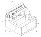
도 1은 본 발명의 일 실시예에 따른 재접착식 메모지용 프린터의 사시도,
도 2는 도 1의 요부 분해 사시도,
도 3은 도 1의 상부 하우징이 제거된 상태의 사시도,
도 4는 도 1의 하우징과 카트리지 케이스의 분해 사시도,
도 5는 도 4의 다른 방향에서 본 분해 사시도,
도 6은 도 3에 메모지가 장착된 상태의 사시도,
도 7은 도 6의 일 측면도,
도 8은 본 발명의 일 실시예에 따른 재접착식 메모지용 프린터로 메모지가 인쇄되는 경로를 도시한 도면,
도 9는 본 발명의 일 실시예에 따른 재접착식 메모지용 프린터로 메모지의 소모에 따른 메모지의 인쇄되는 경로를 도시한 도면,
도 10은 도 1의 피드 롤러의 사시도,
도 11은 도 1의 디컬부의 사시도,
도 12는 도 1의 카트리지 케이스의 사시도,
도 13은 상부 하우징이 분리된 본 발명의 다른 실시예에 따른 재접착식 메모지용 프린터의 사시도,
도 14는 본 발명에 따른 재접착식 메모지용 프린터에 적용되는 메모지의 사시도,
도 15는 도 14의 단면도,
도 16은 도 15의 다양한 형상의 지관에 메모지가 결합된 상태를 도시한 도면,
도 17은 본 발명의 다른 실시예로서 하우징의 수용부의 개략적인 사시도,
도 18은 도 17의 수용부에 재접착식 메모지가 수용된 상태를 도시한 도면,
도 19는 본 발명의 또 다른 실시예로서 하우징의 수용부에 메모지 바스켓이 설치된 상태의 도면,
도 20은 도 19의 메모지 바스켓에 재접착식 메모지가 수용된 상태를 도시한 도면이다.1 is a perspective view of a printer for re-sticky note-paper according to an embodiment of the present invention,
Fig. 2 is an exploded perspective view of the essential part of Fig. 1,
FIG. 3 is a perspective view of the state in which the upper housing of FIG. 1 is removed,
FIG. 4 is an exploded perspective view of the housing and the cartridge case of FIG. 1,
Fig. 5 is an exploded perspective view seen from the other direction of Fig. 4,
Fig. 6 is a perspective view of the state in which the memo is mounted in Fig. 3,
7 is a side view of Fig. 6,
8 is a view illustrating a path for printing a memo with a re-sticky note-paper printer according to an embodiment of the present invention,
FIG. 9 is a view showing a printing path of a memo sheet according to consumption of a memo sheet by a printer for a re-sticky memo pad according to an embodiment of the present invention,
Fig. 10 is a perspective view of the feed roller of Fig. 1,
Fig. 11 is a perspective view of a decal portion of Fig. 1,
12 is a perspective view of the cartridge case of Fig. 1,
13 is a perspective view of a printer for re-sticking note paper according to another embodiment of the present invention in which an upper housing is detached,
FIG. 14 is a perspective view of a note paper applied to a re-sticking note paper printer according to the present invention,
Fig. 15 is a sectional view of Fig. 14,
FIG. 16 is a view showing a state in which a note is combined with a paper tube of various shapes in FIG. 15;
17 is a schematic perspective view of a housing portion of a housing according to another embodiment of the present invention,
Fig. 18 is a view showing a state in which the re-sticking type notepad is received in the receptacle of Fig. 17;
19 is a view showing a state in which a note paper basket is installed in a housing portion of a housing according to another embodiment of the present invention,
Fig. 20 is a view showing a state in which a re-sticking type notepad is accommodated in the notepad basket of Fig. 19;
본 발명의 이점 및 특징, 그리고 그것들을 달성하는 방법은 첨부되는 도면과 함께 상세하게 후술되어 있는 실시예들을 참조하면 명확해질 것이다. 그러나, 본 발명은 이하에서 개시되는 실시예들에 제한되는 것이 아니라 서로 다른 다양한 형태로 구현될 수 있으며, 단지 본 실시예들은 본 발명의 개시가 완전하도록 하고, 본 발명이 속하는 기술 분야의 통상의 기술자에게 본 발명의 범주를 완전하게 알려주기 위해 제공되는 것이며, 본 발명은 청구항의 범주에 의해 정의될 뿐이다.BRIEF DESCRIPTION OF THE DRAWINGS The advantages and features of the present invention, and the manner of achieving them, will be apparent from and elucidated with reference to the embodiments described hereinafter in conjunction with the accompanying drawings. It should be understood, however, that the invention is not limited to the disclosed embodiments, but may be embodied in many different forms and should not be construed as limited to the embodiments set forth herein, Is provided to fully convey the scope of the present invention to a technician, and the present invention is only defined by the scope of the claims.
본 명세서에서 사용된 용어는 실시예들을 설명하기 위한 것이며 본 발명을 제한하고자 하는 것은 아니다. 본 명세서에서, 단수형은 문구에서 특별히 언급하지 않는 한 복수형도 포함한다. 명세서에서 사용되는 "포함한다(comprises)" 및/또는 "포함하는(comprising)"은 언급된 구성요소 외에 하나 이상의 다른 구성요소의 존재 또는 추가를 배제하지 않는다. 명세서 전체에 걸쳐 동일한 도면 부호는 동일한 구성 요소를 지칭하며, "및/또는"은 언급된 구성요소들의 각각 및 하나 이상의 모든 조합을 포함한다. 비록 "제1", "제2" 등이 다양한 구성요소들을 서술하기 위해서 사용되나, 이들 구성요소들은 이들 용어에 의해 제한되지 않음은 물론이다. 이들 용어들은 단지 하나의 구성요소를 다른 구성요소와 구별하기 위하여 사용하는 것이다. 따라서, 이하에서 언급되는 제1 구성요소는 본 발명의 기술적 사상 내에서 제2 구성요소일 수도 있음은 물론이다.The terminology used herein is for the purpose of illustrating embodiments and is not intended to be limiting of the present invention. In the present specification, the singular form includes plural forms unless otherwise specified in the specification. The terms " comprises "and / or" comprising "used in the specification do not exclude the presence or addition of one or more other elements in addition to the stated element. Like reference numerals refer to like elements throughout the specification and "and / or" include each and every combination of one or more of the elements mentioned. Although "first "," second "and the like are used to describe various components, it is needless to say that these components are not limited by these terms. These terms are used only to distinguish one component from another. Therefore, it goes without saying that the first component mentioned below may be the second component within the technical scope of the present invention.
다른 정의가 없다면, 본 명세서에서 사용되는 모든 용어(기술 및 과학적 용어를 포함)는 본 발명이 속하는 기술분야의 통상의 기술자에게 공통적으로 이해될 수 있는 의미로 사용될 수 있을 것이다. 또한, 일반적으로 사용되는 사전에 정의되어 있는 용어들은 명백하게 특별히 정의되어 있지 않는 한 이상적으로 또는 과도하게 해석되지 않는다.Unless defined otherwise, all terms (including technical and scientific terms) used herein may be used in a sense that is commonly understood by one of ordinary skill in the art to which this invention belongs. In addition, commonly used predefined terms are not ideally or excessively interpreted unless explicitly defined otherwise.
이하, 첨부 도면들을 참조하여 본 발명에 대해 상세히 설명한다.DETAILED DESCRIPTION OF THE PREFERRED EMBODIMENTS The present invention will now be described in detail with reference to the accompanying drawings.
설명에 앞서, 여러 실시예에 있어서, 동일한 구성을 가지는 구성요소에 대해서는 동일 부호를 사용하여 대표적으로 일 실시예에서 설명하고, 그 외의 실시예에서는 일 실시예와 다른 구성에 대해서만 설명하기로 한다.Prior to description, elements having the same configuration are denoted by the same reference numerals in representative embodiments, and only other configurations are described for the other embodiments.
도 1 내지 도 12에는 본 발명의 일 실시예에 따른 재접착식 메모지용 프린터가 도시되어 있다.1 to 12 show a printer for a re-sticky note pad according to an embodiment of the present invention.
이들 도면에 도시된 바와 같이, 본 발명의 일 실시예에 따른 재접착식 메모지용 프린터(10)는 하우징(11)과, 인쇄부(31)와, 디컬부(41)를 포함한다.As shown in these drawings, a
하우징(11)은 박스 형상을 가진다. 하우징(11)은 하부 하우징(13)과 상부 하우징(15)이 결합되어 형성된다.The
하부 하우징(13)은 상면이 개방된 박스 형상을 갖고, 상부 하우징(15)은 하부 하우징(13)의 개방된 상면을 커버하도록 마련된다.The
상부 하우징(15)은 하부 하우징(13)의 상면을 개폐할 수 있도록 하부 하우징(13)의 일측에 회전 가능하게 힌지(17)에 의해 결합될 수 있다.The
여기서, 본 실시예에서는 하부 하우징(13)과 상부 하우징(15)이 힌지 결합되는 것으로 도시되어 있지만 이에 한정되지 않고, 상부 하우징(15)과 하부 하우징(13)은 분리 가능하게 결합될 수도 있다. 즉, 도시되어 있지 않지만, 하부 하우징(13)과 상부 하우징(15)은 각각 탄성 결합돌기와 결합홈을 갖고, 탄성 결합돌기가 결합홈에 삽입됨으로써, 분리 가능하게 결합될 수도 있다. 또는, 하부 하우징(13)과 상부 하우징(15)은 나사, 볼트, 핀, 리벳 등의 별도의 체결부재를 통해 분리 가능하게 결합될 수도 있다.Here, although the
하우징(11)은 일 영역에 형성된 점착부(105, 도 14 참조)가 노출되게 롤 형태로 감겨진 재접착식 메모지(101)를 수용하는 수용부(19)를 포함한다. 수용부(19)는 하부 하우징(13)의 내측에 마련되며, 수용부(19)에는 메모지(101)를 수납하는 후술할 카트리지 케이스(51)가 수용된다. 여기서, 수용부(19)에는 카트리지 케이스(51)가 수용되지 않고, 메모지(101)가 수용부(19)의 내측에 회전가능하게 장착될 수도 있다. The
하우징(11)의 상면에는 메모지(101)가 하우징(11)의 외부로 배출되는 배출구(21)가 형성되어 있다. 배출구(21)는 하부 하우징(13)과 상부 하우징(15)의 경계에 형성될 수 있다. 구체적으로, 배출구(21)는 하부 하우징(13)과 힌지 결합되는 상부 하우징(15)의 일단부와 반대되는 타단부와, 상부 하우징(15)의 타단부에 인접하게 마련된 하부 하우징(13)의 일단부가 상호 이격되어 형성될 수 있다.An
여기서, 도시되어 있지 않지만, 본 실시예와 달리 배출구(21)는 하부 하우징(13)의 측면에 형성될 수도 있음은 물론이다.Here, although not shown, it is needless to say that the
또한, 하우징(11)은 수용부(19)와 배출구(21) 사이에 메모지(101)의 이동 경로를 형성한다.In addition, the
인쇄부(31)는 메모지(101)의 이동 경로에 마련되어, 메모지(101)에 화상을 형성 예컨대, 인쇄를 행한다.The
인쇄부(31)는 배출구(21)로 배출되는 메모지(101)에 인쇄를 행하는 써멀 헤드(33)와, 써멀 헤드(33)와의 사이에 인쇄 닙(nip)을 형성하고 메모지(101)의 감겨진 방향으로 회전하며 써멀 헤드(33)를 가압하는 피드 롤러(35)를 포함한다.The
써멀 헤드(33)는 인쇄 닙을 통과하는 메모지(101)에 열을 가하여 메모지(101)에 화상이 형성되도록 한다. 써멀 헤드(33)는, 도시되어 있지 않지만, 복수의 발열소자를 가지며, 복수의 발열소자 중 일부를 선택적으로 발열시킬 수 있다. 복수의 발열소자는 복수의 발열 저항체와, 발열 저항체를 발열시키는 전극과, 발열 저항체 및 전극을 보호하는 보호층을 포함하여 구성될 수 있다.The
메모지(101)는 써멀 헤드(33)가 발열하면 이에 반응하여 발색(發色)할 수 있다. 일 예로, 메모지(101)는 써멀 헤드(33)에 의해 열을 받은 부분만 검은색으로 변할 수 있다. 이를 위해, 메모지(101)는 감열층(107)을 포함할 수 있다.When the
피드 롤러(35)는 도 10에 도시된 바와 같이 원통 형상을 가지며, 메모지(101)를 이송하고, 메모지(101)를 사이에 두고 써멀 헤드(33)에 가압할 수 있다. 피드 롤러(35)는 메모지(101)를 가압하며 배출구(21)를 향해 배출시킨다. 피드 롤러(35)는 이송 모터(미도시)로부터 구동력을 전달받아 회전축(39)을 중심으로 회전한다. 구체적으로, 피드 롤러(35)는 하우징(11)에 수용된 메모지(101)가 풀리는 메모지(101)의 회전방향의 반대방향으로 회전한다. 피드 롤러(35)와 이송 모터의 사이에는 동력 전달을 위한 동력 전달유닛(미도시)이 마련될 수도 있다.The
한편, 피드 롤러(35)는 일단부에 단차부(37)를 형성하며 회전축(39)에 결합되어 있다. 메모지(101)의 점착부(105)의 이동 경로에 대응하는 위치에 배치된 피드 롤러(35)의 외주는 나머지 외주에 비해 상대적으로 직경이 작은 크기를 갖는 단차부(37)를 형성한다.On the other hand, the
이로써, 메모지(101)가 써멀 헤드(33)와 피드 롤러(35) 사이를 통과하며 인쇄되는 도중에, 메모지(101)의 점착부(105)에 의해 인쇄부(31)가 오염되는 것을 방지할 수 있게 된다.This makes it possible to prevent the
여기서, 메모지(101)의 점착부(105)의 이동 경로에 대응하는 위치에 배치된 피드 롤러(35)의 외주에는, 도시되어 있지 않지만 다른 실시예로서 메모지(101)의 점착부(105)와 마찰력에 의해 가압 접촉하지 않고, 자전가능하게 구름 접촉하는 폭이 작은 롤링 휠이 마련될 수도 있다.Although not shown in the drawing, the outer periphery of the
또한, 써멀 헤드(33)는 하부 하우징(13)에 마련되고, 피드 롤러(35)는 상부 하우징(15)에 마련될 수 있다. 이로써, 상부 하우징(15)을 개방하여 메모지(101)를 수용부(19)에 수용한 후, 수용부(19)에 수용된 메모지(101)의 일부를 써멀 헤드(33)의 상측에 위치시킨 상태에서 상부 하우징(15)을 폐쇄하여 써멀 헤드(33)와 피드 롤러(35) 사이에 메모지(101)를 위치시킬 수 있다. 상부 하우징(15)을 폐쇄함에 따라 피드 롤러(35)는 메모지(101)를 사이에 두고 써멀 헤드(33)와 접하며 인쇄 닙을 형성할 수 있다. 아울러, 상부 하우징(15)을 폐쇄함에 따라 피드 롤러(35)는 이송 모터로부터 동력을 전달받을 수 있게 된다. . 한편, 이러한 피드 롤러(35)는 피드 롤러(35)를 통과하는 재접착식 메모지(101)에 메모지(101)의 감겨진 방향과 반대방향의 컬을 발생하여, 메모지(101)의 컬을 해소할 수 있다. The
디컬부(41)는 수용부(19)와 인쇄부(31) 사이의 메모지(101) 이동 경로에 마련된다. 디컬부(41)에서 메모지(101)는 디컬부(41)와 슬라이딩 접촉한다. 예컨대, 하우징(11)으로부터 풀려 인쇄부(31)로 공급되는 메모지(101)는 디컬부(41)에 의해 메모지(101)의 감겨진 방향의 반대 방향으로 굴곡지도록 안내한다. 이로써, 인쇄부(31)로 공급되는 메모지(101)의 컬을 해소하거나 완화시킨다.The
디컬부(41)는 도 11에 도시된 바와 같이 복수의 단위 슬라이딩바아(45)가 슬라이딩바아 축(43)에 간격을 두고 결합된 구성을 가진다. 각 단위 슬라이딩바아(45)는 원통 형상을 가지며, 복수의 단위 슬라이딩바아(45) 중 메모지(101)의 점착부(105)의 이동 경로에 대응하는 위치에 배치된 단위 슬라이딩바아(45)는 다른 단위 슬라이딩바아(45)들에 비해 직경이 상대적으로 작은 크기의 단차 슬라이딩바아(47)를 가진다. 이에 의해, 디컬부(41)는 메모지(101)의 점착부(105)의 이동 경로에 대응하는 위치에 축경(縮徑)된 단차를 형성한다.The
이로써, 메모지(101)의 점착부(105)가 이동 경로를 따라 인쇄부(31)로 이동하는 도중에, 디컬부(41)의 표면에 점착부(105)가 접촉하지 않게 되어, 메모지(101)와 디컬부(41)의 접착에 따른 메모지(101)의 이동이 저지되어 오작동이 발생하는 것을 방지할 수 있게 된다.The
여기서, 다른 실시예로서 도시되어 있지 않지만, 디컬부(41)는 축에 자전가능하게 결합된 하나 이상의 롤러로 구성될 수도 있다. 이와 같이, 디컬부(41)가 롤러로 구성된 경우, 디컬부(41)를 통과하는 메모지(101)의 점착부(105)는 롤러가 구름 운동함에 따라 손상되지 않게 된다.Here, although not shown as another embodiment, the
이러한 디컬부(41)에 의해, 인쇄부(31)로 이송되는 메모지(101)의 평탄도가 향상됨에 따라, 본 발명의 일 실시예에 따른 재접착식 메모지용 프린터(10)는 인쇄 품질을 향상시킬 수 있으며, 메모지(101)가 피드 롤러(35) 및 배출구(21)에 걸리는 메모지 걸림 현상이 방지되어, 인쇄된 메모지(101)가 원활하게 배출되며, 배출된 메모지(101)를 깔끔하게 부착하며 보관할 수 있게 된다.As the flatness of the
여기서, 본 실시예에서의 디컬부(41)는 복수의 단위 슬라이딩바아(45)와 단차 슬라이딩바아(47)가 슬라이딩바아 축(43)에 간격을 두고 결합된 것으로 도시되어 있지만 이에 한정되지 않고, 디컬부(41)는 하나의 원통 형상으로 이루어짐과 동시에, 메모지(101)의 점착부(105)의 이동 경로에 대응하는 위치에 배치된 디컬부(41)의 외주는 나머지 디컬부(41)의 외주에 비해 상대적으로 직경이 작은 크기를 갖는 단차가 형성될 수도 있다.Although the plurality of
또한, 본 실시예에서는 디컬부(41)가 수용부(19)와 인쇄부(31) 사이의 메모지(101) 이동 경로에 마련되는 것으로 도시되어 있지만 이에 한정하지 않고, 디컬부(41)는 인쇄부(31)와 배출구(21) 사이에 마련될 수도 있다.In the present embodiment, although the
한편, 이하에서는 본 발명에 따른 재접착식 메모지용 프린터(10)에 적용되는 재접착식 메모지(101)에 대해 간략히 설명한다. 본 발명의 프린터(10)에 적용되는 재접착식 메모지(101)는 도 14 및 도 15에 도시된 바와 같이, 기재(103)와, 프린터(10)에 의해 화상이 인쇄되는 감열층(107)이 적층되는 구조를 가진다.Hereinafter, a
기재(103)는 결합의 기본이 되는 재료로서, 각종 종이류, 플라스틱류 등으로 이루어질 수 있다.The
기재(103)의 일 영역에는 점착제가 도포된 점착부(105)가 마련된다. 점착부(105)는 기재(103)의 일측 변을 따라 예컨대, 메모지(101)의 이동 방향을 따라 일정의 폭으로 마련된다. 점착부(105)는 부착된 메모지(101)를 다시 떼어낼 수 있고, 떼어낸 메모지(101)를 재부착할 수 있도록 적절한 재점착력을 갖는 점착제가 도포된다. 여기서, 본 실시예에서는 점착부(105)가 기재(103)의 일 영역에만 마련되는 것으로 도시되어 있지만 이에 한정되지 않고, 점착부(105)는 기재(103)의 전체 영역에 마련될 수도 있다.In one region of the
감열층(107)은 기재(103)의 전면에 감열제가 도포되어 형성된다.The heat-
감열층(107)의 일 영역에는 이형제가 도포된 이형층(109)이 마련된다. 이형층(109)은 메모지(101)가 롤 형태로 감긴 상태에서 점착부(105)에 의해 기재(103)와 감열층(107)이 붙게 되는 현상을 방지하고, 메모지(101)가 풀리는 과정에서 기재(103)와 감열층(107)이 잘 떨어지도록 할 수 있다. 이형층(109)은 실리콘 수지, 폴리비닐알코올, 파라핀, 왁스류 등의 이형제로 형성될 수 있다.In one region of the heat-
이형층(109)은 점착부(105)가 마련된 영역에 대응되도록 마련된다. 예컨대, 점착부(105)가 기재(103)의 일 영역에만 마련된 경우 이형층(109)은 감열층(107)의 일 영역에만 마련될 수 있다. 또한, 점착부(105)가 기재(103)의 전체 영역에 마련된 경우 이형층(109)은 감열층(107)의 전체 영역에 마련될 수 있다. 여기서, 이형층(109)은 메모지(101)가 롤 형태로 감길 때 발생하는 정렬 오차를 고려하여, 점착부(105)의 폭보다 크게 마련될 수도 있다.The
본 발명의 프린터(10)에 적용되는 메모지(101)는 지관(111)의 둘레를 따라 점착부(105)가 노출되게 롤 형태로 감겨진 상태로 마련된다.The
한편, 본 발명의 일 실시예에 따른 재접착식 메모지용 프린터(10)는 메모지(101)를 수납하며, 메모지(101)의 중심을 위치 고정하는 카트리지 케이스(51)를 더 포함한다.The re-sticking
카트리지 케이스(51)는 수용부(19)에 착탈가능하게 마련된다. 카트리지 케이스(51)는, 도 12에 도시된 바와 같이, 좌우로 분리가능하게 결합되는 제1카트리지 케이스(53)와 제2카트리지 케이스(57)를 포함한다.The
일 예로, 제1 카트리지 케이스(53)에는 걸림돌기(55)가 마련되며 제2카트리지 케이스(57)에는 걸림홈(59)이 마련되어, 제1카트리지 케이스(53)와 제2 카트리지 케이스(57)는 걸림돌기(55)가 걸림홈(59)에 후크 결합되며 분리 가능하게 결합될 수 있다. 다만, 제1카트리지 케이스(53)와 제2카트리지 케이스(57)가 분리 가능하게 결합되는 방식은 이에 제한되지 않으며, 제1카트리지 케이스(53)와 제2카트리지 케이스(57)는 나사 결합을 통해 분리 가능하게 결합될 수도 있다.For example, the
제1카트리지 케이스(53)와 제2카트리지 케이스(57)는 동일 외경을 가지며, 이에 제1카트리지 케이스(53)와 제2카트리지 케이스(57)는 함께 결합되어, 전체적으로 단차가 없는 원통 형상을 형성한다. 또한. 제1카트리지 케이스(53)와 제2카트리지 케이스(57)는 각각 내부에 메모지(101)가 감싸지며 수납되는 메모지 수납부(61)를 형성한다. 메모지 수납부(61)에는 지관(111)에 롤 형태로 감겨진 메모지(101)가 수납되며, 이 때 메모지(101)의 점착부(105)는 외부로 노출된다.The
한편, 제1카트리지 케이스(53)의 내경은 제2카트리지 케이스(57)의 내경보다 크게 형성하여, 전체적으로 제1카트리지 케이스(53) 및 제2카트리지 케이스(57)가 형성하는 메모지 수납부(61)는 확경(擴徑)된 단차를 형성 예컨대, 이격부(52)를 형성한다.The inner diameter of the
그리고, 이격부(52)가 형성된 제1카트리지 케이스(53)의 메모지 수납부(61) 측에 메모지(101)의 점착부(105)가 위치하도록 메모지(101)를 수납함으로써, 메모지(101)의 점착부(105)가 메모지 수납부(61)에 수납 및 이동 경로를 따라 인쇄부(31)로 이동하는 도중에, 제1카트리지 케이스(53)의 내측에 접촉하지 않게 되어, 메모지(101)의 이동이 저지되어 오작동이 발생하는 것을 방지할 수 있게 된다.The
여기서, 본 실시예에서는 제1카트리지 케이스(53)의 내경이 제2카트리지 케이스(57)의 내경보다 크게 형성되는 것으로 설명하고 있지만 이에 한정되지 않고, 제2카트리지 케이스(57)의 내경이 제1카트리지 케이스(53)의 내경보다 크게 형성되고, 이 때 확경된 단차를 형성한 제2카트리지 케이스(57)의 메모지 수납부(61) 측에 메모지(101)의 점착부(105)가 위치하도록 메모지(101)를 수납할 수도 있다.In the present embodiment, the inner diameter of the
또한, 제1카트리지 케이스(53)와 제2카트리지 케이스(57)는 각각 수납된 메모지(101)를 위치 고정하되, 회전가능하게 장착되는 메모지 홀더(63)를 포함한다. 메모지 홀더(63)는 제1카트리지 케이스(53)와 제2카트리지 케이스(57)의 각각의 내측면에 형성된다. 메모지 홀더(63)는 메모지 지관(111)의 양단부를 회전가능하게 지지하며, 메모지(101)의 회전 중심축선을 형성한다. The
구체적으로, 메모지 홀더(63)는 원통 형상을 가지고, 제1카트리지 케이스(53)와 제2카트리지 케이스(57)의 각각의 내측면으로부터 돌출되며, 메모지(101)가 감겨진 지관(111)의 회전 중심홀의 양단부가 메모지 홀더(63)에 각각 회전가능하게 장착된다. 여기서, 메모지 홀더(63)의 형상은 이에 한정되지 않고, 도시되어 있지 않지만 메모지 지관(111)의 회전 중심에 원통형 샤프트를 마련하고, 메모지(101)의 폭 방향을 따라 미리 설정된 길이만큼 돌출되고 메모지 홀더(63)는 원통형 샤프트의 양단이 회전가능하게 수용되는 수용홈 형상을 가지도록 하여, 메모지(101)를 회전가능하게 장착할 수도 있다.Specifically, the
따라서, 메모지 홀더(63)는 메모지(101)의 회전 중심의 위치를 고정시켜 메모지(101)가 소모되어 감겨진 메모지(101)의 반경이 감소하더라도 회전 중심의 위치가 변경되지 않는다. 한편, 메모지(101)의 회전 중심축선을 형성하는 메모지 홀더(63)는 하우징(11)의 바닥에 대해 디컬부(41)의 중심축선보다 더 높은 위치에 위치한다.The position of the center of rotation of the
또한, 도시되어 있지 않지만, 제1카트리지 케이스(53)와 제2카트리지 케이스(57)의 각 메모지 홀더(63)의 외경을 달리하고, 메모지(101)가 감겨진 지관(111)의 양단부의 내경을 달리하여, 메모지(101)가 감겨진 지관(111)을 카트리지 케이스(51)에 수납하여 각 메모지 홀더(63)에 장착시, 메모지(101)의 수납방향을 용이하게 식별할 수 있고, 잘못 수납되는 것을 방지할 수도 있다. Although not shown, the outer diameter of each
또한, 본 실시예에서는 재접착식 메모지(101)가 카트리지 케이스(51)에 수납되는 것으로 도시되어 있지만 이에 한정되지 않고, 재접착식 메모지(101)는 도 18에 도시된 바와 같이 하우징(11)의 수용부(19)에 직접 장착될 수도 있으며, 이 경우 하우징(11)의 수용부(19)는 도 17에 도시된 바와 같이 재접착식 메모지(101)의 점착부(105)에 대응하는 위치에 단차(19a)를 형성하여, 재접착식 메모지(101)의 점착부(105)가 하우징(11)의 수용부(19)의 내측면에 접촉하여 손상되는 것을 방지할 수도 있다.Although the
또한, 재접착식 메모지(101)는 도 20에 도시된 바와 같이 하우징(11)의 수용부(19)에 착탈가능하게 수용되는 메모지 바스켓(25)에 수납될 수 있으며, 이 경우 메모지 바스켓(25)은 도 19에 도시된 바와 같이 재접착식 메모지(101)의 점착부(105)에 대응하는 위치에 단차(25a)를 형성하여, 재접착식 메모지(101)의 점착부(105)가 메모지 바스켓(25)의 내측면에 접촉하여 손상되는 것을 방지할 수도 있다.20, the
한편, 카트리지 케이스(51)의 일측에는 메모지(101)를 인쇄부(31)로 공급하기 위한 인출구(65)가 형성되어 있다. 인출구(65)는 카트리지 케이스(51)의 길이방향을 따라 부분 절취되어 있다.On the other hand, a draw-out
또한, 카트리지 케이스(51)는 하우징(11)에 착탈하기 위한 착탈수단을 더 포함한다.Further, the
착탈수단은, 도 4 및 도 5에 도시된 바와 같이, 제1카트리지 케이스(53) 및 제2카트리지 케이스(57)의 외측면에 돌출 형성된 돌출돌기(67a,67b)와, 하우징(11)의 수용부(19) 내측면에 함몰 형성되어 돌출돌기(67a,67b)가 끼움 결합되는 끼움홈(69a,69b)을 포함한다.As shown in Figs. 4 and 5, the detachment means includes protruding
제1카트리지 케이스(53)의 외측면에는 하나의 사각기둥 형상의 제1돌출돌기(67a)가 일정 길이만큼 돌출 형성되어 있고, 제2카트리지 케이스(57)의 외측면에는 2개의 제2돌출돌기(67b)가 일정 길이만큼 돌출 형성되어 있다.A
이에 대응하여, 하우징(11)의 수용부(19) 내측면에는, 제1카트리지 케이스(53)와 제2카트리지 케이스(57)의 각 돌출돌기(67a,67b)의 대응하는 위치에 각각 끼움홈(69a,69b)이 함몰 형성되어 있다. 각 끼움홈(69a,69b)은 돌출돌기(67a,67b)의 단면에 대응하는 형상을 가진다. 돌출돌기(67a,67b)와 끼움홈(69a,69b)의 형상은 이에 한정되지 않고, 다양한 단면 형상을 가질 수 있다.Corresponding to this, on the inner side surface of the receiving
이에 따라, 카트리지 케이스(51)는 하우징(11)의 수용부(19)에 장착 및 고정될 수 있다. 또한, 제1카트리지 케이스(53)와 제2카트리지 케이스(57)에 각각 구비된 돌출돌기(67a,67b)의 수량을 달리함으로써, 카트리지 케이스(51)를 하우징(11)의 수용부(19)에 장착시, 카트리지 케이스(51)의 수납방향을 용이하게 식별할 수 있고, 잘못 장착되는 것을 방지할 수 있다. 따라서, 메모지(101)가 하우징(11)의 수용부(19)에 잘못 수납되는 것을 방지할 수 있다.Accordingly, the
여기서, 본 실시예에서는 착탈수단으로서 돌출돌기(67a,67b)가 제1카트리지 케이스(53) 및 제2카트리지 케이스(57)에 돌출 형성되고, 끼움홈(69a,69b)이 하우징(11)의 수용부(19) 내측면에 함몰 형성되는 것으로 도시되어 있지만 이에 한정되지 않고, 돌출돌기(67a,67b)는 하우징(11)의 수용부(19) 내측면에 돌출 형성되고, 끼움홈(69a,69b)은 제1카트리지 케이스(53) 및 제2카트리지 케이스(57)에 함몰 형성되어, 카트리지 케이스(51)를 하우징(11)에 착탈할 수도 있다.In this embodiment, the protruding
그리고, 본 실시예에서는 카트리지 케이스(51)가 동일 외경을 갖는 원통 형상으로 형성된 것으로 도시되어 있지만 이에 한정되지 않고, 카트리지 케이스(51)에 외경이 다른 단차를 형성하고, 이에 대응하여 하우징(11)의 수용부(19)의 내경을 다르게 형성하여 하우징(11)의 수용부(19)에 단차를 형성할 수도 있다. 이에 따라, 카트리지 케이스(51)를 하우징(11)의 수용부(19)에 장착시 카트리지 케이스(51)와 하우징(11)의 수용부(19)의 단차에 의해, 카트리지 케이스(51)의 수납방향을 용이하게 식별할 수 있고, 잘못 장착되는 것을 방지할 수 있다. In this embodiment, the
또한, 도시되어 있지 않지만, 카트리지 케이스(51)를 좌우방향 또는 상하방향으로 비대칭적으로 형성하고, 이에 대응하여 하우징(11)의 수용부(19)를 비대칭적으로 형성하여, 카트리지 케이스(51)가 하우징(11)의 수용부(19)에 잘못 장착되는 것을 방지할 수 있다.Although not shown, the
한편, 본 발명의 일 실시예에 따른 재접착식 메모지용 프린터(10)는, 이동 경로에 마련되어, 디컬부(41)로 이동하는 메모지(101)의 처짐을 방지하는 처짐 방지 가이드(71)를 더 포함한다.The re-sticking
처짐 방지 가이드(71)는 하우징(11)에 마련되어, 메모지(101)의 이동 경로의 일 영역을 형성하며 디컬부(41)를 부분적으로 둘러싸도록 만곡되게 형성된다. 처짐 방지 가이드(71)가 디컬부(41)를 부분적으로 둘러싸며 형성됨에 따라, 처짐 방지 가이드(71)와 디컬부(41) 사이의 이동 경로를 따라 이동하는 메모지(101)는 디컬부(41)에 의해 느슨하게 처지지 않게 됨과 동시에, 디컬부(41)에 의해 장력이 부여된다. The
처짐 방지 가이드(71)의 선단부(73)에서는 메모지(101)가 슬라이딩 이동한다. 처짐 방지 가이드(71)의 선단부(73)는 라운드지게 형성되며, 하우징(11)의 바닥에 대해 메모지 회전 중심축선의 높이 이상의 위치에 위치한다.The
즉, 본 발명의 일 실시예에 따른 재접착식 메모지용 프린터(10)는, 도 8에 도시된 바와 같이, 카트리지 케이스(51)에 롤 형태로 감겨져 디컬부(41)로 이동하는 메모지(101)가 하우징(11)의 상방으로부터 하방을 향해 이동하는 구조를 가지므로, 처짐 방지 가이드(71)의 선단부(73)가 하우징(11)의 바닥에 대해 메모지 회전 중심축선의 높이 보다 낮을 경우, 카트리지 케이스(51)에 수납된 메모지(101)가 소모되어, 감겨진 메모지(101)의 회전 반경이 작아지면, 디컬부(41)와 카트리지 케이스(51)의 인출구(65) 사이에 위치하는 메모지(101)가 느슨해져 처짐이 발생하게 된다. 이에 의해, 디컬부(41)로 공급되는 메모지(101)는 중첩하며 디컬될 염려가 있고, 또한 인쇄부(31)로의 메모지(101)의 이동 불량이 발생할 뿐만 아니라 인쇄 품질의 불량을 초래한다.8, the re-sticking
따라서, 디컬부(41)와 카트리지 케이스(51) 사이에 처짐 방지 가이드(71)를 마련하고, 처짐 방지 가이드(71)의 선단부(73)는 하우징(11)의 바닥에 대해 메모지 회전 중심축선의 높이 이상의 위치에 위치시킴으로써, 도 9에 도시된 바와 같이 카트리지 케이스(51)에 수납된 메모지(101)가 소모되어, 감겨진 메모지(101)의 회전 반경이 작아지더라도 디컬부(41)와 카트리지 케이스(51)의 인출구(65) 사이에 위치하는 메모지(101)는 처짐 방지 가이드(71)에 의해 처짐이 발생하지 않게 되어, 인쇄부(31)로의 메모지(101)의 이동 불량 및 인쇄 품질의 불량을 방지할 수 있게 된다.The
여기서, 본 실시예에서는 처짐 방지 가이드(71)가 하우징(11)에 마련되는 것으로 도시되어 있지만 이에 한정되지 않고, 처짐 방지 가이드(71)는 카트리지 케이스(51)의 인출구(65)에 인접하게 카트리지 케이스(51)에 마련될 수도 있다.In this embodiment, the
또한, 본 발명의 일 실시예에 따른 재접착식 메모지용 프린터(10)는 커팅부(81)를 더 포함할 수 있다.In addition, the
커팅부(81)는 도 8에 도시된 바와 같이, 고정 나이프(83)와, 모터(미도시)의 구동력에 의해 고정 나이프(83)에 대해 접근 및 이격하여 메모지(101)를 커팅하는 이동 나이프(85)를 포함할 수 있다.8, the cutting
이에 따라, 인쇄부(31)를 통과한 연속적인 메모지(101)는 커팅부(81)에 의해 단위 메모지(101)로 커팅될 수 있다. 단위 메모지(101)는 배출구(21)를 통해 프린터(10)의 외부로 배출될 수 있다.The
이러한 구성에 의하여, 본 발명의 일 실시예에 따른 재접착식 메모지용 프린터(10)는, 도 8에 도시된 바와 같이, 점착부(105)가 노출되게 롤 형태로 감겨진 상태의 메모지(101)가 카트리지 케이스(51)로부터 인출되어, 처짐 방지 가이드(71)를 거쳐, 디컬부(41)에 의해 굴곡된 메모지(101)의 컬이 완화되거나 펴지면서 인쇄부(31)로 공급되어, 인쇄부(31)의 써멀 헤드(33)를 통해 화상 등이 인쇄된 후, 배출구(21)를 통해 배출된다.8, the
한편, 카트리지 케이스(51)로부터 인출된 메모지(101)는 처짐 방지 가이드(71)에 의해 느슨해지지 않고 디컬부(41)로 공급되고, 디컬부(41)는 인쇄부(31)로 공급되는 메모지(101)의 컬을 해소하거나 완화하여 메모지(101)의 평탄도가 향상되어, 인쇄부(31)를 통한 인쇄 품질이 향상될 뿐만 아니라 메모지(101)가 이동 경로 상에서 걸리는 걸림 현상이 방지되고, 인쇄된 메모지(101)가 원활하게 배출되며, 배출된 메모지(101)를 깔끔하게 부착하며 보관할 수 있게 된다.The
한편, 본 발명의 일 실시예에 따른 재접착식 메모지용 프린터(10)는 적어도 일 영역에 형성된 점착부(105)가 노출되게 지관(111)에 롤 형태로 감겨진 메모지(101)가 카트리지 케이스(51)에 수납되어 인쇄부(31)로 공급하는 것으로 도시되어 있지만 이에 한정되지 않고, 본 발명의 다른 실시예에 따른 재접착식 메모지용 프린터(10′)는 지관(111)에 롤 형태로 감겨진 재접착식 메모지(101)는 카트리지 케이스에 수납되지 않고 하우징(11)의 수용부(19)에 직접 장착될 수도 있다.The
이와 같이, 지관(111)에 롤 형태로 감겨진 재접착식 메모지(101)를 하우징(11)의 수용부(19)에 직접 장착하는 경우, 도 16의 (a)에 도시된 바와 같이 지관(111)의 양단부를 상이한 외경(D1,D2)으로 형성하고, 도 13에 도시된 바와 같이 하우징(11)의 내측면에 지관(111)의 양단부의 상이한 외경에 각각 대응하는 내경의 크기를 갖는 제1장착홈(91)과 제2장착홈(93)을 형성하여 예컨대, 일 예로서 제1장착홈(91)의 내경을 제2장착홈(93)의 내경보다 작게 할 수 있다. 제1장착홈(91)과 제2장착홈(93)에는 메모지(101)가 감겨진 지관(111)이 회전가능하게 장착된다.16 (a), when the
각 장착홈(91,93)은 지관(111)의 각 단부의 외경(D1,D2)의 폭으로 하우징(11)의 상부면으로부터 일정 길이만큼 장공 형상으로 함몰 형성되고, 각 장착홈(91,93)에 장착되는 메모지 지관(111)은 하우징(11)의 바닥에 대해 디컬부 (41)의 슬라이딩바아(45,47)의 중심축선보다 더 높은 위치에서 메모지(101)의 회전 중심축선을 형성하며 회전할 수 있다.Each of the mounting
이에 따라, 지관(111)의 양단부를 상이한 외경으로 형성하고, 하우징(11)의 내측면에 지관(111)의 양단부의 상이한 외경에 각각 대응하는 제1장착홈(91)과 제2장착홈(93)을 형성함으로써, 롤 형태로 지관(111)에 감겨진 메모지(101)가 하우징(11)의 수용부(19)에 잘못 수납되는 것을 방지할 수 있다.The
또한, 다른 실시예로서, 도 16의 (b)에 도시된 바와 같이 메모지(101)가 롤 형태로 감겨진 지관(111)의 양단부를 각각 상호 다른 길이(L1,L2)로 돌출시켜, 롤 형태로 지관(111)에 감겨진 메모지(101)가 하우징(11)의 수용부(19)에 잘못 수납되는 것을 방지할 수도 있다. 16 (b), both ends of the
이상, 첨부된 도면을 참조로 하여 본 발명의 실시예를 설명하였지만, 본 발명이 속하는 기술분야의 통상의 기술자는 본 발명이 그 기술적 사상이나 필수적인 특징을 변경하지 않고서 다른 구체적인 형태로 실시될 수 있다는 것을 이해할 수 있을 것이다. 그러므로, 이상에서 기술한 실시예들은 모든 면에서 예시적인 것이며, 제한적이 아닌 것으로 이해해야만 한다.While the present invention has been described in connection with what is presently considered to be practical exemplary embodiments, it is to be understood that the invention is not limited to the disclosed embodiments, but, on the contrary, You will understand. Therefore, it should be understood that the above-described embodiments are illustrative in all aspects and not restrictive.
10 : 재접착식 메모지용 프린터 11 : 하우징
19 : 수용부 21 : 배출구
31 : 인쇄부 33 : 써멀 헤드
35 : 피드 롤러 37 : 단차부
41 : 디컬부 47 : 단차 슬라이딩바아
51 : 카트리지 케이스 61 : 메모지 수납부
63 : 메모지 홀더 65 : 인출구
67a,67b : 돌출돌기 69a,69b : 끼움홈
71 : 처짐 방지 가이드 91 : 제1장착홈
93 : 제2장착홈10: printer for re-sticking note paper 11: housing
19: receptacle 21: outlet
31: Printing section 33: Thermal head
35: feed roller 37: stepped portion
41: diagonal portion 47: step difference sliding bar
51: cartridge case 61: note storage compartment
63: note pad holder 65: outlet
67a, 67b: projecting
71: deflection prevention guide 91: first mounting groove
93: second mounting groove
Claims (13)
상기 이동 경로에 마련되어 상기 배출구로 배출되는 상기 메모지에 인쇄를 행하는 써멀 헤드와, 상기 메모지의 점착부의 이동 경로에 대응하는 위치에 축경(縮徑)된 단차를 형성하며 상기 하우징에 수용된 상기 메모지가 풀리는 상기 메모지의 회전방향의 반대방향으로 회전하고 상기 써멀 헤드를 가압하며 상기 메모지를 이송하는 피드 롤러를 갖는 인쇄부를 포함하는, 재접착식 메모지용 프린터.And a discharge port through which the memo paper drawn out from the accommodating portion is discharged, wherein between the accommodating portion and the discharge port, A housing for forming a path of movement of the housing; And
A thermal head which is provided in the movement path and performs printing on the memo paper discharged to the discharge port; and a step of forming a stepped portion having a reduced diameter at a position corresponding to the movement path of the adhering portion of the memo paper, And a printing unit having a feed roller which rotates in a direction opposite to the rotation direction of the note paper and presses the thermal head and feeds the note paper.
상기 이동 경로에 마련되어, 상기 메모지의 점착부의 이동 경로에 대응하는 위치에 축경(縮徑)된 단차를 형성하며, 상기 메모지가 상기 메모지의 감겨진 방향의 반대 방향으로 굴곡지도록 안내하는 디컬부를 포함하는, 재접착식 메모지용 프린터.The method according to claim 1,
And a decoupling portion provided on the movement path and forming a stepped portion having a reduced diameter at a position corresponding to a movement path of the adhesive portion of the note paper and guiding the note paper to bend in a direction opposite to the winding direction of the note paper , Printer for re-adhesive note paper.
상기 메모지가 롤 형태로 감겨진 지관의 양단부의 외경은 상이한 크기를 가지며,
상기 수용부는 상이한 외경을 갖는 상기 지관의 양단부에 대응하는 내경의 크기를 갖는 제1장착홈 및 제2장착홈을 형성하며, 상이한 외경을 갖는 상기 지관은 상기 제1장착홈 및 상기 제2장착홈에 회전가능하게 장착되는, 재접착식 메모지용 프린터.The method according to claim 1,
The outer diameters of the both ends of the paper tube wound in the form of rolls have different sizes,
Wherein said receiving portion has a first mounting groove and a second mounting groove each having a size of an inner diameter corresponding to both ends of said branch pipe having different outer diameters and said branch pipe having a different outer diameter is formed in said first mounting groove and said second mounting groove And the second housing is rotatably mounted on the second housing.
상기 수용부에 착탈가능하게 마련되고, 상기 메모지를 수납하며 상기 메모지의 중심을 위치 고정하는 카트리지 케이스를 더 포함하는, 재접착식 메모지용 프린터.The method according to claim 1,
And a cartridge case detachably provided in the accommodating portion, the cartridge case housing the memo paper and fixing the center of the memo paper.
상기 카트리지 케이스는,
상기 메모지를 수납하는 메모지 수납부;
상기 메모지가 회전가능하게 장착되는 메모지 홀더; 및
상기 메모지 수납부에 수납된 상기 메모지를 상기 인쇄부로 공급하기 위한 인출구를 포함하는, 재접착식 메모지용 프린터.5. The method of claim 4,
The cartridge case includes:
A memo storage unit for storing the memo;
A note holder on which the note is rotatably mounted; And
And a feed-out port for feeding the note stored in the note storage compartment to the printing unit.
상기 카트리지 케이스의 메모지 수납부는, 감겨진 상기 메모지의 점착부가 대응하는 위치에 확경(擴徑)된 단차가 형성된, 재접착식 메모지용 프린터. 6. The method of claim 5,
Wherein the notch storage portion of the cartridge case has a stepped portion formed at a position corresponding to the adhered portion of the wrapped note.
상기 하우징의 수용부는, 상기 롤 형태로 감겨진 재접착식 메모지의 점착부에 대응하는 위치에 상기 점착부와 접촉하지 않도록 단차가 형성된, 재접착식 메모지용 프린터. The method according to claim 1,
Wherein the accommodating portion of the housing has a stepped portion formed at a position corresponding to the adhered portion of the re-sticky note wrapped in the roll form so as not to contact the adhered portion.
상기 하우징의 수용부에 수용되며 상기 롤 형태로 감겨진 재접착식 메모지를 수납하는 메모지 바스켓을 더 포함하며,
상기 메모지 바스켓에는 상기 재접착식 메모지의 점착부에 대응하는 위치에 상기 점착부와 접촉하지 않도록 단차가 형성된, 재접착식 메모지용 프린터. The method according to claim 1,
And a memo paper basket accommodated in the receiving portion of the housing and storing the re-sticky note wrapped in the roll form,
And the stepped basket is formed with a stepped portion at a position corresponding to the adhering portion of the re-sticking type memo so as not to contact the adhering portion.
상기 메모지가 롤 형태로 감겨진 지관의 양단부는 상호 다른 길이로 돌출된, 재접착식 메모지용 프린터.The method according to claim 1 or 4,
Wherein both ends of the paper tube wound with the roll paper are protruded with mutually different lengths.
상기 메모지가 롤 형태로 감겨진 지관의 양단부의 내경은 상이한 크기를 갖는, 재접착식 메모지용 프린터.The method according to claim 1 or 4,
Wherein the inner diameter of both end portions of the paper tube wound with the roll paper is different in size.
상기 카트리지 케이스에는 외경이 다른 단차를 형성하고, 이에 대응하여 상기 하우징의 수용부에는 내경이 다른 단차가 형성된, 재접착식 메모지용 프린터. 5. The method of claim 4,
Wherein a stepped portion having a different outer diameter is formed in the cartridge case, and a stepped portion having a different inner diameter is formed in the receiving portion of the housing in correspondence with the stepped portion.
상기 카트리지 케이스는 좌우방향 또는 상하방향으로 비대칭적으로 형성되고, 이에 대응하여 상기 하우징의 수용부는 비대칭적으로 형성된, 재접착식 메모지용 프린터. 5. The method of claim 4,
Wherein the cartridge case is formed asymmetrically in the left-right direction or the up-down direction, and the accommodating portion of the housing is formed asymmetrically correspondingly.
Priority Applications (5)
| Application Number | Priority Date | Filing Date | Title |
|---|---|---|---|
| KR1020160152570A KR101712404B1 (en) | 2016-11-16 | 2016-11-16 | Printer for repositionable note |
| US15/683,206 US20180134049A1 (en) | 2016-11-16 | 2017-08-22 | Printer for repositionable note |
| JP2017158971A JP6535711B2 (en) | 2016-11-16 | 2017-08-22 | Printer for re-adhesive type note paper |
| EP17201660.2A EP3323620B1 (en) | 2016-11-16 | 2017-11-14 | Printer for repositionable note |
| US16/781,087 US20200171850A1 (en) | 2016-11-16 | 2020-02-04 | Printer for repositionable note |
Applications Claiming Priority (1)
| Application Number | Priority Date | Filing Date | Title |
|---|---|---|---|
| KR1020160152570A KR101712404B1 (en) | 2016-11-16 | 2016-11-16 | Printer for repositionable note |
Publications (1)
| Publication Number | Publication Date |
|---|---|
| KR101712404B1 true KR101712404B1 (en) | 2017-03-06 |
Family
ID=58399002
Family Applications (1)
| Application Number | Title | Priority Date | Filing Date |
|---|---|---|---|
| KR1020160152570A KR101712404B1 (en) | 2016-11-16 | 2016-11-16 | Printer for repositionable note |
Country Status (1)
| Country | Link |
|---|---|
| KR (1) | KR101712404B1 (en) |
Cited By (2)
| Publication number | Priority date | Publication date | Assignee | Title |
|---|---|---|---|---|
| KR102004412B1 (en) * | 2018-11-14 | 2019-07-26 | 망고슬래브 주식회사 | Printer |
| KR102026311B1 (en) * | 2019-02-27 | 2019-09-27 | 망고슬래브 주식회사 | Printer |
Citations (2)
| Publication number | Priority date | Publication date | Assignee | Title |
|---|---|---|---|---|
| KR20120048675A (en) * | 2009-09-11 | 2012-05-15 | 가부시키가이샤 미마키 엔지니어링 | Printer device and roller assembly |
| KR20160094252A (en) * | 2015-01-30 | 2016-08-09 | 삼성전자주식회사 | Image forming apparatus, printing method of note and computer readable storage medium |
-
2016
- 2016-11-16 KR KR1020160152570A patent/KR101712404B1/en active IP Right Grant
Patent Citations (2)
| Publication number | Priority date | Publication date | Assignee | Title |
|---|---|---|---|---|
| KR20120048675A (en) * | 2009-09-11 | 2012-05-15 | 가부시키가이샤 미마키 엔지니어링 | Printer device and roller assembly |
| KR20160094252A (en) * | 2015-01-30 | 2016-08-09 | 삼성전자주식회사 | Image forming apparatus, printing method of note and computer readable storage medium |
Cited By (6)
| Publication number | Priority date | Publication date | Assignee | Title |
|---|---|---|---|---|
| KR102004412B1 (en) * | 2018-11-14 | 2019-07-26 | 망고슬래브 주식회사 | Printer |
| WO2020101066A1 (en) * | 2018-11-14 | 2020-05-22 | 망고슬래브 주식회사 | Printer |
| US11247491B2 (en) | 2018-11-14 | 2022-02-15 | Mangoslab Co., Ltd. | Printer |
| KR102026311B1 (en) * | 2019-02-27 | 2019-09-27 | 망고슬래브 주식회사 | Printer |
| CN111619239A (en) * | 2019-02-27 | 2020-09-04 | 网谷思乐福有限公司 | Printer with a movable platen |
| CN111619239B (en) * | 2019-02-27 | 2022-01-28 | 网谷思乐福有限公司 | Printer with a movable platen |
Similar Documents
| Publication | Publication Date | Title |
|---|---|---|
| JP6453977B2 (en) | Media processing apparatus with improved media and ribbon loading and unloading characteristics | |
| US7686244B2 (en) | Paper roll feed mechanism, paper roll feed cassette, and image forming apparatus | |
| US11679607B2 (en) | Printing device | |
| US20200171850A1 (en) | Printer for repositionable note | |
| KR101712404B1 (en) | Printer for repositionable note | |
| US11235601B2 (en) | Printer | |
| US5727883A (en) | Winding member for winding an ink sheet, housing member for housing such a winding member, and recording apparatus for recording on a recording medium by use of such a housing member | |
| KR101712403B1 (en) | Printer for repositionable note | |
| US9950543B2 (en) | Cartridge for recording medium and image forming apparatus having the same | |
| KR100318642B1 (en) | Print cartridge | |
| JP2006306511A (en) | Rolled sheet cue mechanism, paper feeding cassette and printer | |
| JP3549370B2 (en) | Cartridge and recording device using this cartridge | |
| JP4819536B2 (en) | Cassettes and printers | |
| JP2007160801A (en) | Roll-paper feed mechanism, roll-paper feeding cassette, and image forming device | |
| JP3782275B2 (en) | Ribbon cassette | |
| US12145357B2 (en) | Printing device | |
| JP7383912B2 (en) | cassette | |
| US9764572B2 (en) | Printer | |
| JP4256154B2 (en) | Thermal transfer printer | |
| CN118163497A (en) | Printing device | |
| JP2021024701A (en) | Printer | |
| JP2001183803A (en) | Device for coating sensitized material |
Legal Events
| Date | Code | Title | Description |
|---|---|---|---|
| E701 | Decision to grant or registration of patent right | ||
| GRNT | Written decision to grant | ||
| FPAY | Annual fee payment |
Payment date: 20200213 Year of fee payment: 4 |