KR101633500B1 - Spin Exchange Relaxation Free Atomic Magnetometer - Google Patents
Spin Exchange Relaxation Free Atomic Magnetometer Download PDFInfo
- Publication number
- KR101633500B1 KR101633500B1 KR1020140145495A KR20140145495A KR101633500B1 KR 101633500 B1 KR101633500 B1 KR 101633500B1 KR 1020140145495 A KR1020140145495 A KR 1020140145495A KR 20140145495 A KR20140145495 A KR 20140145495A KR 101633500 B1 KR101633500 B1 KR 101633500B1
- Authority
- KR
- South Korea
- Prior art keywords
- cell
- magnetic field
- vapor
- heating
- probe beam
- Prior art date
Links
Images


Landscapes
- Measuring Magnetic Variables (AREA)
- Measurement And Recording Of Electrical Phenomena And Electrical Characteristics Of The Living Body (AREA)
Abstract
The present invention provides an atomic magnetometer without spin exchange relaxation. The atomic magnetometer without relaxation of the spin exchange includes a hexahedral main cell and a cylindrical stem cell connected to the main cell, and is provided with a circularly polarized pump beam and a linearly polarized probe beam, ; A sensing unit for receiving the linearly polarized probe beam transmitted through the vapor cell and measuring a polarization state of the probe beam; And a heating unit for heating the steam cell by applying alternating current of 20 kHz to 60 kHz to the hot line. The measuring field of the object of measurement provides a photomagnetic rotation of the probe beam in the vapor cell.
Description
Field of the Invention [0002] The present invention relates to an atomic magnetometer without spin exchange, and more particularly, to an atomic magnetometer without a spin exchange relaxation including a heating portion using alternating hot wire.
Development and measurement / analysis of biomagnetic measurement devices based on optical pumping atomic magnetometer technology, which is a super-sensitive magnetic field sensor (magnetometer), such as cardiac / cerebral angiography, is a trend of the 21st century, Development and measurement of biomagnetic measurement devices based on optical pumping atomic magnetometer technology, which is a ultra-sensitive magnetic field sensor (magnetometer) of ultra-high sensitivity instantaneous diagnosis system in the era of ubiquitous health (U-Health) / Analytical technology is the core of technology for next-generation ultra-sensitive instant diagnostic systems in the era of ubiquitous health (U-Health), which pursues a 21st century trend of safe life and healthy life.
In particular, high-sensitivity magnetic field measurement technology has been studied with a wide range of interest from pure science to industry. The magnetic field measurement technique differs depending on the measurement range. Recently, a small atomic magnetometer has been developed by P. Schwindt of NIST and it is expected to be applied to portable magnetic resonance imaging, buried explosive detector, remote minerometer and the like because it is combined with ubiquitous technology.
The recently studied Spin Exchange Relaxation Free (SERF) atomic magnetometers can be used without refrigerant at room temperature while showing sensitivity comparable to SQUID sensors. Therefore, SERF-based atomic magnetometers can be applied to all SQUID precision measurement fields that have been studied for a long time. As a result, the development of atomic magnetometer technology will become an opportunity to further deepen and develop excellent magnetic measurement application technology.
In particular, the SERF type atomic magnetometer will be widely applied to the development of non-cooling brain / heart rate measurement technology. The combination of SERF atomic magnetometer technology, biomagnetic measurement technology, atomic clock technology, and spectroscopy technology is expected to lead the world in the field of atomic magnetometers. Future research will be widely applied to the development of precision absolute magnetic field measurement technology and the development of various magnetic field based nondestructive inspection techniques.
Conventionally, the techniques used for precision magnetic measurement have been studied by various methods such as magnetic resonance (nuclear magnetic resonance, optical pumping), Hall effect, and magnetometer using fluxgate principle. It has various advantages and disadvantages depending on the measurement method of the magnetic field. The fluxgate magnetometer is simple to measure because of its simple measurement method, but it has limitations to the authors' measurement.
The magnetic field is the most fundamental and conveys information about all electromagnetic phenomena to one of the observable physical quantities anywhere. Highly sensitive magnetic field measurement technology has been studied with wide interest from pure science to industrial. Currently, SQUID-based sensors are the most sensitive magnetic field measuring devices most sensitive to magnetic fields. However, the theoretical limitations and the cost of cryogenic cooling for superconducting phenomena, and the cost of maintaining and managing it, are so widespread.
To overcome this problem, researches on magnetometers using interaction of light and resonant atoms are actively being conducted. The sensitivity of these atomic magnetometers is more than or more than the sensitivity of SQUID-based magnetometers. This enables biomagnetic fields, which could only be measured with a SQUID sensor, to be measured through an atomic magnetometer that does not require cooling and maintenance, making it possible to use biomagnetism diagnostic techniques such as epilepsy, brain function mapping, myocardial infarction, arrhythmia, Can be widely disseminated.
Recently, studies on the measurement of micro-magnetic field using the interaction of atom and laser have been conducted in theory and experiment.
The Scully group theoretically calculated the limit of the measurement of the small magnetic field due to the nonlinear magneto-optical effect in the coherent atomic medium. According to this study, the limit of magnetic field measurement sensitivity is reported as 0.6 fT / Hz 1/2 when using Rb atoms.
In 2003, the Romalis group showed that it is possible to measure the magnetic field with a sensitivity of 0.54 fT / Hz 1/2 by detecting Lamor spin precession by optical pumping
In 2004, the Hollberg group of NIST developed a magnetic field measurement sensor with a height of 3.9 mm and a volume of 12 mm 3 using the coherent density trapping (CPT) phenomenon. The sensitivity of this sensor was measured at about 50 pT / Hz 1/2 .
In 2006, the Budker Group developed a magnetic field sensor by fabricating a 3 mm diameter spherical cell with anti-relaxation coating. The sensitivity of this sensor is reported to be measured at 4 pT / Hz 1/2 .
Recently, a small atomic atomic magnetometer was developed by P. Schwindt of NIST and it is expected to be applied to portable magnetic resonance imaging, buried explosive detectors, remote minerals measuring instruments and the like by combining with ubiquitous technology.
Recently, in the Romalis group, we developed an atomic magnetometer with a magnetic field measurement sensitivity of 160 aT / Hz 1/2 in the Spin-exchange relaxation free (SERF) region at the potassium atom.
A problem to be solved by the present invention is to measure the intensity and direction of an external magnetic field through the interaction of atoms and light with the spin spinning motion of an atom changing by an external magnetic field to measure a small metallic material or a micro magnetic field generated in the living body And to provide a device for performing the above-described operations. AC power of a predetermined frequency band is applied to the heating wire for heating the stable steam cell. In addition, using a negative feedback, a small magnetic field measurement is possible.
The atomic magnetometer without spin exchange relaxation according to an embodiment of the present invention includes a hexahedral main cell and a cylindrical stem cell connected to the main cell and is provided with a circularly polarized pump beam and a linearly polarized probe beam, A vapor cell comprising a metal vapor; A sensing unit for receiving the linearly polarized probe beam transmitted through the vapor cell and measuring a polarization state of the probe beam; And a heating unit for heating the steam cell by applying alternating current of 5 kHz to 30 kHz to the heat line. The measuring field of the object of measurement provides a photomagnetic rotation of the probe beam in the vapor cell.
In one embodiment of the present invention, the vapor cell comprises a main cell comprising potassium metal (K), helium buffer gas, and nitrogen gas as alkali metal vapor; And a stem cell for preventing adsorption of the alkali metal vapor.
In one embodiment of the present invention, a first heating unit for heating a main cell of the steam cell to 200 degrees Celsius by applying an alternating current of 5 kHz to 30 kHz to the heat line; And a second heating unit for heating the stem cell to 185 degrees Celsius by applying alternating current of 5 kHz to 30 kHz to the heat line.
In one embodiment of the present invention, the heating unit includes a first heating block including a through hole on a lower surface and a transparent window on a side surface, the heating block surrounding the main cell; A first heating coil arranged to surround an outer circumferential surface of the first heating block; A second heating block aligned with the through-holes of the first heating block and surrounding the stem cell; A second heating coil disposed to surround the second heating block; And an insulating block for receiving the first heating block and the first heating block, wherein the main cell can be aligned with the transparent window of the first heating block.
In one embodiment of the present invention, a negative feedback magnetic field signal, which is perpendicular to the first plane, is generated in a first plane defined by the traveling direction of the probe beam and the pump beam, A feedback coil provided; And a feedback amplifier for providing a feedback current to the feedback coil to generate a feedback magnetic field in response to the output signal of the sensing unit and proportional to the measurement magnetic field.
In one embodiment of the present invention, the feedback coil and the feedback amplifier may extend the detection band width of the atomic magnetometer.
In one embodiment of the present invention, the frequency response of the atomic magnetometer can be flat from hundreds of Hz to zero Hz.
In one embodiment of the present invention, the frequency response of the feedback amplifier may have a flat gain from DC to 20 kHz, or pass a DC to cutoff frequency, and the cutoff frequency may be 150 to 220 Hz .
In one embodiment of the present invention, the magnetic shield may further include a magnetic shield disposed around the steam cell and configured to reduce an external magnetic field to remove an external environmental magnetic field.
In one embodiment of the present invention, the apparatus may further include a magnetic field canceling unit disposed around the steam cell to generate a magnetic field for canceling an external environmental magnetic field.
In one embodiment of the present invention, the heating unit includes a heating coil for heating the steam cell, a temperature measurement unit for measuring a temperature of the heated steam cell, an opio amplifier for providing AC power to the heating coil, And a
According to the embodiment of the present invention, it is possible to heat the atomic magnetometer in a stable manner without affecting the measurement signal, by providing alternating current of a predetermined band to the hot wire.
According to an embodiment of the present invention, the detection bandwidth of the atomic magnetometer can be extended by using a reduced feedback in the SERF region.
According to one embodiment of the present invention, a flat-to-frequency response from zero to 190 Hz is achieved when using the use of abbreviated feedback. The flat-frequency response is a 3-fold increase over the case of not using the use of the reduced feedback, while maintaining a sensitivity of 3 fT / Hz 1/2 at 100 Hz.
1 is a conceptual diagram illustrating an atomic magnetometer according to an embodiment of the present invention.
FIG. 2A is a block diagram illustrating the abatement feedback of the atomic magnetometer of FIG. 1 under a test magnetic field.
FIG. 2B is a block diagram illustrating the reduced feedback of the atomic magnetometer of FIG. 1 under a measurement magnetic field.
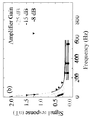
3 is a graph showing the frequency response of the atomic magnetometer of FIG.
4 is a perspective view illustrating an atomic magnetometer according to another embodiment of the present invention.
5 is a plan view illustrating the atomic magnetometer of FIG.
6 is a perspective view illustrating the heat insulating block of the atomic magnetometer of FIG.
7 is an exploded perspective view for explaining the heat insulating block of FIG. 6 and the heating block therein.
8 is a cross-sectional view taken along line I-I 'of FIG.
Figure 9 is a block diagram illustrating the cancellation of the residual magnetic field.
10 is a block diagram for explaining measurement of a measurement magnetic field to be measured.
11 is a view for explaining a method of measuring a polarization rotation angle according to an embodiment of the present invention.
12 is a view for explaining a method of measuring the polarization rotation angle according to another embodiment of the present invention.
13 is a view for explaining a method of measuring the polarization rotation angle according to another embodiment of the present invention.
14 is a diagram showing a photomagnetic rotation signal according to a function of a test magnetic field By in the SERF region.
15 shows the frequency response of the atomic magnetometer of FIG.
16 is a diagram showing the frequency response for an input oscillating magnetic field having an amplitude of 600 pT for multiple frequencies.
FIG. 17A shows a test magnetic field in the frequency domain, FIG. 17B shows a measurement signal in the time domain in which the test magnetic field signal of FIG. 17A is measured, and FIG. 17C is an enlarged graph of the measurement signal of FIG.
18 is a graph showing a noise spectrum of an atomic magnetometer according to an embodiment of the present invention.
19 is a conceptual diagram showing an atomic magnetometer according to another embodiment of the present invention.
Optical magnetometer using light has been actively developed as a way to overcome the limitations of SQUIDs. To date, the study of the field of optical magnetometers can be summarized in two major directions. A method of measuring the degree of change of the refractive index of the medium by the magnetic field and a method of measuring the degree of movement of the magnetic sub-level. The former is called an optical pumping magnetometer (OPM), and the latter is called a coherent population trapping magnetometer (CPTM).
The basic atomic magnetometer principle is to measure the external magnetic field by measuring the Larmor wash frequency of the atomic spin under magnetic field.
The sensitivity of the atomic magnetometer is determined by the line width and noise of the measured signal. There are two ways to improve the sensitivity of atomic magnetometers.
The first is to prevent collisions with the wall of the vapor cell containing atoms and atoms. In this method, a vapor cell containing a buffer gas and a vapor cell coated with paraffin are used. In general, the most significant factor in the coalescence time between the bottom levels of alkaline atoms is the collision of atoms and walls of the vapor cell. The buffer gas uses molecules that do not affect the change in coherence state even though they collide with alkaline atoms, such as He and N 2 . These buffer gases prevent diffusion of alkaline atoms into the vapor cell wall and increase the interaction time between alkaline atoms and the irradiation beam.
The second method is to improve atomic density. In the second method, when the atomic density increases, the spin exchange collisions between alkaline atoms dominate the sensitivity of the magnetometer. In this case, the atomic spin is preserved, but the atomic coherence is relaxed.
Recently, there is known a spin exchange relaxation method that completely eliminates the relaxation caused by the spin exchange collision between the bottom levels. The SERF magnetometer is a typical OPM. If the Larmor frequency is much lower than the spin exchange rate between atoms under a weak magnetic field, the relaxation due to spin exchange can be reduced. In such a composition, the atoms move in the same direction as the direction of carburization of each atom, but the carburized frequency is washed off at the average frequency. That is, the atomic frequency of the atoms is slower than the atomic frequency of each atom, and the atoms stay longer at the atomic level. A magnetometer based on this method empirically has a sensitivity of 0.54 fT / Hz 1/2 and theoretically has a sensitivity of 0.01 fT / Hz 1/2 .
In recent years, atomic magnetometers have been developed using vapor cells manufactured in micrometer sizes, which are about 10 mm 3 in volume. These devices are simple to move and require a small laser power of several mW. The total device size is also less than 10 cm 3 .
In an atomic magnetometer, the polarization of an atom aligned in a certain direction by a pump beam (e.g., magnetic moment) is changed by an external magnetic field. At this time, the polarization state of the atoms can be found by measuring the degree of polarization rotation of the irradiation beam. That is, the polarization rotation angle of the irradiation beam is measured and the atomic state of the magnetic field is measured to measure the magnetic field. Generally, the directions of the pump beam and the irradiation beam are perpendicular to each other. However, in the CPT-based composition, the directions of the two light beams are the same because circularly polarized light components whose directions of rotation are opposite to each other are used as the pump beam and the irradiation beam.
In order to improve the sensitivity to the external magnetic field, coherence relaxation by spin relaxation should be minimized. Spin relaxation is mitigated by spin-exchange collisions, spin-fracture relaxation, and collisions with wall surfaces of glass containers containing coherent media. At high atomic densities, spin - exchange collisions between coherent densities contribute most to spin relaxation. In this collision, the spin directions of the two atoms change according to the spin discrimination, but the total momentum is preserved.
This effect is due to the interaction between the alkali and alkali metals used in the experiment as a coherent medium with the potentials of spin singlet and triplet. The very large energy difference between a singlet and a triplet positive gives rise to a phase difference of the wave function in the collision between alkali metal atoms, resulting in the exchange of the spin states of the electrons. The spin-exchange collisions do not affect the nuclear spins of colliding atoms because they occur very quickly in the interaction between ultrafine atomic levels. However, due to collisions, atoms exchange ultrafine states. In other words, redistribution of atoms occurs between magnetic levitation levels due to spin exchange collisions. In atomic superfine energy, the two ground levels have the same frequency but opposite direction washings, resulting in coherence relaxation between the two superfine energies. However, if the atom density is high enough under a small magnetic field, that is, if the spin-exchange ratio is sufficiently larger than the carburizing frequency, then each of the atoms will move at a very small angle. Therefore, all the atoms in the bottom level (Zeeman) magnetic sublevel have very small cycles. Atoms stay at the F = I + 1/2 level for a longer period of time where relatively more but the Zeeman sublevel is present. Especially, the atoms are polarized at the mF = I + 1/2 magnetic sublevel of the F = I + 1/2 level, and all the atoms are subjected to the car motion with the same frequency as the same direction. In this way, the atoms at the two microns level have the same precession motion, and spin-exchange collisions no longer affect spin relaxation.
In order to eliminate the spin-exchange relaxation, a small magnetic field of several nT and a high density of the medium are required. In addition, the magnetic field around the vapor cell should not exist except for the magnetic field to be measured. In order to generate a magnetic field of several nT, a magnetic field cancellation coil should be made perpendicular to the plane of advance of the laser to adjust the magnetic field around the medium to close to 0 T in the magnetic shielding device. In order to generate a magnetic field of several nT, a magnetic field canceling coil should be formed in the traveling direction and the horizontal direction of the laser so that the magnetic field around the medium in the magnetic field shielding device is adjusted to be close to 0 T (Tesla).
Higher temperatures are required to increase the density of the vaporous medium. The potassium atom to be used in the experiment is an alkaline metal atom, and a spin-exchange collision occurs sufficiently at about 200 degrees centigrade. The optimum conditions for the spin-exchange collision are determined by the atomic density of atoms and the cross-sectional area between the atoms and the temperature. The impingement cross-sectional area of the potassium atom is 110 -18 cm 2 and the required density is 10 14 -10 15 cm -3 .
According to an embodiment of the present invention, a method of controlling the temperature of the temperature regulating device uses a method of generating heat by flowing an alternating current of 5 kHz to 30 kHz to the resistor. The magnetic field caused by the current of the temperature regulating device generates a magnetic field of 5 kHz to 30 kHz. However, the 5 kHz to 30 kHz band is hardly affected by the low frequency response of the vapor cell. Therefore, the AC current resistance wire heating method can significantly reduce the space compared to the conventional temperature control method using the heating fluid. In addition, a thermal insulation device is required to keep the steam cell in order to maintain the temperature. The heat insulating device can be easily disassembled and coupled through the fitting using a PTFE material.
Among the various atomic magnetometers, the most probable type for biomagnetic measurements is the SERF atomic magnetometer. By completely eliminating the relaxation caused by the spin-exchange collision, the SERF magnetometer can reach a sensitivity of 0.1 fT / Hz 1/2 . However, the long spin-coherence time of the SERF magnetometer limits the bandwidth of the magnetometer.
Several methods have been reported to extend the bandwidth of atomic magnetometers. Self-oscillating magnetometers have a bandwidth exceeding 1 kHz by feeding modulated power back to the light source. With a high density atomic cell, the bandwidth reaching 10 kHz can be obtained by increasing the optical pumping rate. However, such a system has a sensitivity as low as 10 fT / Hz 1/2 . Thus, such a system can not measure weak bio-magnetic signals such as human MEG.
Recently, the reduced feedback principle has been applied to a radio frequency atomic magnetometer (RF atomic magnetometer). It is reported that the bandwidth is widened to more than 1 kHz around 423 kHz.
Suppression of spin coherence time under reduced feedback is related to spin damping. The RF atomic magnetometer with spin damping exhibits a sensitivity of 0.3 fT / Hz 1/2 . However, for practical applications to detect time-varying biomagnetic fields, the center frequency should approach direct current (DC). However, such a structure is incompatible with RF atomic magnetometers.
According to one embodiment of the present invention, a SERF-type highly sensitive atomic magnetometer is disclosed. In order to increase the sensitivity of the magnetic field and ensure the frequency domain for precise measurement of the brain / heart rate, a reduced feedback is provided to the vapor cell containing the alkali metal vapor. In addition, the reduced feedback reduces the signal-to-noise ratio and provides a broad bandwidth, allowing measurement of small and rapidly changing magnetic field signals.
According to one embodiment of the present invention, it is proposed to use a reduced feedback to extend the detection bandwidth of an atomic magnetometer in the SERF region.
According to one embodiment of the present invention, a flat-to-frequency response from zero to 190 Hz is achieved when using the use of abbreviated feedback. The flat-frequency response maintains a noise level of 3 fT / Hz 1/2 at 100 Hz and exhibits a 3-fold increase compared to the use of the reduced feedback.
With the above bandwidth expansion, the linear correlation between the magnetocardiographic field and the synthesized signal for comparison with the measured signal was increased from 0.21 to 0.74. This result shows the feasibility of weak biomagnetic signals including multiple frequency components using a SERF atomic magnetometer under a negative feedback.
According to one embodiment of the present invention, we apply the reduced feedback to a SERF based atomic magnetometer. An increase of three times the bandwidth causes nearly flat-response in the frequency domain from DC to 190 Hz. The noise level is 3 fT / Hz 1/2 at 100 Hz.
Respectively. This noise level is similar to the noise level of the DC SQUID.
The entire system of the SERF atomic magnetometer can be assumed to be an amplifier with a single pole in the frequency response. The signals measured under the reduced feedback showed a high correlation coefficient.
Hereinafter, preferred embodiments of the present invention will be described in detail with reference to the accompanying drawings. However, the present invention is not limited to the embodiments described herein but may be embodied in other forms. Rather, the embodiments disclosed herein are being provided so that this disclosure will be thorough and complete, and will fully convey the concept of the invention to those skilled in the art. In the drawings, the components have been exaggerated for clarity. Like numbers refer to like elements throughout the specification.
1 is a conceptual diagram illustrating an atomic magnetometer according to an embodiment of the present invention.
FIG. 2A is a block diagram illustrating the abatement feedback of the atomic magnetometer of FIG. 1 under a test magnetic field.
FIG. 2B is a block diagram illustrating the reduced feedback of the atomic magnetometer of FIG. 1 under a measurement magnetic field.
3 is a graph showing the frequency response of the atomic magnetometer of FIG.
1 to 3, the
The
The
The
The
The
A pump light source may output the
The pump light source may deliver a circularly
The irradiation light source may output the
A test coil generates a test magnetic field (Bt). The
The
The
The negative feedback field B fb can be given as:
![]()
Here, β is a feedback gain, and Vout is an electrical signal at the output of the
Referring to FIG. 3, as the
Increasing the linearity of the output of the
Like other systems involving resonance, the SERF atomic magnetometer exhibits a Lorentzian-type response in the frequency domain. The Lorentzian-type response has a center frequency at about zero Hz and a cut-off frequency fc. Therefore, the open-loop gain G can be expressed in the Lorentzian form as follows.

Where G 0 is the DC gain, f is the frequency, and fc is the cutoff frequency.
Under the reduced feedback situation, the feedback gain G fb can be expressed as:

Where beta is a feedback gain parameter. The frequency response of the atomic magnetometer extends the bandwidth to a 1 + β G 0 factor and the bandwidth extension reduces the DC gain to 1 + β G 0 factor. The bandwidth extension can measure the input signal (measuring magnetic field) without distortion due to the flat frequency characteristics.
Depending on the frequency band of the measuring magnetic field, the feedback gain parameter? Can be selected appropriately. The feedback gain parameter beta may be adjusted by controlling the gain of the feedback amplifier.
In applications measuring pulsed magnetic fields with strong higher-order harmonics, the increased bandwidth improves the linearity of the output signal of the
4 is a perspective view illustrating an atomic magnetometer according to another embodiment of the present invention.
5 is a plan view illustrating the atomic magnetometer of FIG.
6 is a perspective view illustrating the heat insulating block of the atomic magnetometer of FIG.
7 is an exploded perspective view for explaining the heat insulating block of FIG. 6 and the heating block therein.
8 is a cross-sectional view taken along line I-I 'of FIG.
Figure 9 is a block diagram illustrating the cancellation of the residual magnetic field.
10 is a block diagram for explaining measurement of a measurement magnetic field to be measured.
4 to 9, the
The
The
The
The
In addition, the
Since the application of the biomagnetic measurement technique using the
There may be a residual magnetic field inside the magnetic shield cylinder, and an absolute magnetic field is required in the SERF system. Therefore, a magnetic field cancellation coil system composed of several independent coils inside the shield can be constructed for the purpose of shielding the magnetic field, so that it can form a magneto magnetic field and can form oblique magnetic fields and uniform long fields in various directions.
An active magnetic shielding technique can be applied to eliminate spin-exchange relaxation. A magnetic
The magnetic
The magnetic
The x-axis amplifier 173a may provide the first reference frequency signal f1 REF to the x-axis offset
The x-axis cancellation
The z-axis cancellation
In this case, the first reference frequency component f1 AM of the x-axis lock amplifier 173a is proportional to the z-axis residual magnetic field component, and the second reference frequency component f2 AM of the z-
The
Before measuring the measurement magnetic field Bmeas generated by the
The
Also, the
The magnetic
The magnetic
The y-axis canceling current (Y DC) flowing in the y-axis canceling coil, the x-axis canceling current (x DC) flowing in the x-axis canceling coil, and the z-axis canceling current (Z DC) Can be measured. Conversely, conversely, the y-axis canceling current (Z DC), the x-axis canceling current (X DC), and the z-axis canceling current (Z DC) can provide respective offset magnetic field components.
The y-axis canceling current (Y DC), the x-axis canceling current (X DC), and the z-axis canceling current (Z DC) are set such that the respective offset magnetic field components are provided to the vapor cell Thereby making the residual magnetic field zero.
The pump
The irradiation
The
The
A
The SERF method requires high atomic density. Therefore, the optimum temperature of the potassium vapor is 200 degrees Celsius, and the heating part and the heat insulating part are constituted for this. In the heating method, the temperature was controlled by applying current to the resistor using a heating method using a hot wire. In order to prevent the induced magnetic field induced by the alternating current from affecting the state of the potassium atom, a current modulated at a high frequency of 5 kHz to 30 kHz was applied. That is, since the cut-off frequency fc of the reduced feedback SERF atomic magnetometer is several hundreds Hz, a high frequency heating current of 5 kHz to 30 kHz has little effect on the reduced feedback SERF atomic magnetometer.
The
The
The
The
The
The
The
The
The central
The upper insulating
The upper surface of the
The outer
The atomic magnetometer according to an embodiment of the present invention includes a hexahedral main cell and a cylindrical stem cell connected to the main cell, and is provided with a circularly polarized pump beam and a linearly polarized irradiation beam, and includes an alkali metal vapor A steam cell; A sensing unit for receiving the linearly polarized irradiation beam transmitted through the vapor cell and measuring a polarization state of the irradiation beam; And a heating unit for heating the steam cell by applying alternating current of 5 kHz to 30 kHz to the heat line. The measuring field of the object to be measured provides a photomagnetic rotation of the irradiation beam in the vapor cell.
In one embodiment of the present invention, the vapor cell comprises a main cell comprising potassium metal (K), helium buffer gas, and nitrogen gas as alkali metal vapor; And a stem cell for preventing adsorption of the alkali metal vapor.
In one embodiment of the present invention, a first heating unit for heating a main cell of the steam cell to 200 degrees Celsius by applying an alternating current of 5 kHz to 30 kHz to the heat line; And a second heating unit for heating the stem cell to 185 degrees Celsius by applying alternating current of 5 kHz to 30 kHz to the heat line.
In one embodiment of the present invention, the heating unit includes a first heating block including a through hole on a lower surface and a transparent window on a side surface, the heating block surrounding the main cell; A first heating coil arranged to surround an outer circumferential surface of the first heating block; A second heating block aligned with the through-holes of the first heating block and surrounding the stem cell; A second heating coil disposed to surround the second heating block; And an insulating block for receiving the first heating block and the first heating block. The main cell may be aligned with the transparent window of the first heating block.
In applications as a micro-magnetic field measuring device, the ability to measure the polarization rotation angle is very important.
11 is a view for explaining a method of measuring a polarization rotation angle according to an embodiment of the present invention.
Referring to FIG. 11, a balanced polarimeter is used as the
The
The

Where I 1 + I 2 = I 0 and θ is the polarization rotation angle. In the case of a small polarization rotation angle (θ << 1), the polarization rotation angle can be given by the intensity difference of the two lights.

The output of the
In accordance with an embodiment of the present invention, the output of the
The operation method of the atomic magnetometer according to an embodiment of the present invention provides the circularly polarized pump beam and the linearly polarized irradiation beam to the
Wherein the step of detecting the polarization rotation signal comprises the steps of: dividing the irradiation beam transmitted through the vapor cell into a first polarized beam and a second polarized beam having different polarization directions from each other, measuring the intensity of the first polarized beam, Measuring the intensity of the polarization beam and extracting the polarization rotation angle signal using the difference between the first measurement signal of the first polarized beam and the second measurement signal of the second polarized beam.
The operation method of the atomic magnetometer may further include generating a cancellation magnetic field to remove an external environmental magnetic field affecting the
12 is a view for explaining a method of measuring the polarization rotation angle according to another embodiment of the present invention.
12, the
The
The
A magnetic field that oscillates at a modulation frequency (ω mod ) of several kHz can modulate the polarization direction of the irradiation light at a very small angle due to the Faraday rotation effect. Thereafter, the modulated light is subjected to photomagnetic rotation by an angle passing through the

I 0 is the intensity of the light transmitted through the

The lock-in
The
According to an embodiment of the present invention, the output of the
The method of operating an atomic magnetometer according to an embodiment of the present invention includes: providing a circularly polarized pump beam and a linearly polarized irradiation beam to a
The step of detecting the polarization rotation signal may include the steps of modulating the polarization rotation angle of the irradiation beam at a predetermined modulation frequency in front of the
13 is a view for explaining a method of measuring the polarization rotation angle according to another embodiment of the present invention.
13, the
The
A photoelastic modulator is used as the
If the light passing through the
When this light passes through a
![]()
I 0 is the intensity of the light transmitted through the vapor cell 110. ? mod is the modulation angular frequency? mod , and ? is the modulation amplitude. The modulation frequency component (primary harmonic signal) of the intensity of the light is proportional to the rotation angle [theta] and is given as follows.

The lock-in
The method of operating an atomic magnetometer according to an embodiment of the present invention includes providing a circularly polarized pump beam and a linearly polarized irradiation beam to a
The step of detecting the polarization rotation signal may include the step of modulating the polarization rotation angle of the irradiation beam at a predetermined modulation frequency by transmitting the 1/4
14 is a diagram showing a photomagnetic rotation signal according to a function of a test magnetic field By in the SERF region.
Referring to FIG. 14, the photomagnetic rotation signal may be proportional to the optical rotation angle when a balanced polarimeter is used. The solid line is the theoretical result given by the steady state solution of the block equation. The circle represents the measurement result.
15 shows the frequency response of the atomic magnetometer of FIG.
Referring to FIG. 15, the
The resonance curve of the disperse type indicates the polarization rotation of the irradiation beam with respect to the transverse magnetic field By. The sensitivity of the
In our experimental conditions, the laser intensities of the pump beam and the irradiation beam were measured as 33 mW / cm 2 and 5 mW / cm 2 , respectively.
In the DC By magnetic field, the slope of the signal determines G o . As a result of the measurement, G 0 is 0.6 V / nT. A sinusoidal electrical signal of 350 mVpp is provided at the input of the
16 is a diagram showing the frequency response for an input oscillating magnetic field having an amplitude of 600 pT for multiple frequencies.
Referring to FIG. 16, the incident beam intensities of the pump beam and the irradiation beam are 33 mV / cm 2 and 5 mW / cm 2, respectively. The measured data was fitted to the Lorentz type. fc represents the half width at half maximum of the fitted Lorentz type. The half-width can be treated as the cut-off frequency (cut-off frequency) of the single pole amplifier. For open-loop, fc is 72 Hz. For pulsed loops with reduced feedback, fc can increase to 195 Hz.
In order to investigate the frequency response of the
Without a reduced feedback, data for frequencies below 50 Hz can not be measured by photodiode output saturation.
For β = 3.5 nT / V, the curve of the frequency response is nearly flat to a half-width of 195 Hz. According to equation (3), fc is multiplied by (1 + βG 0 ) factor and G fb by (1 + βG 0 ) factor. The calculated fc for 0.5, 0.2, and 3.5 nT / V are given as 93.6, 158, and 223 Hz, respectively.
The experimentally obtained cut-off frequency (fc) is given as 80, 110, and 195 Hz for 0.5, 0.2, and 3.5 nT / V, respectively. However, the experimental values 80,110, and 195 and the calculated values 93.6,158, and 223 are almost similar.
The performance of the feedback system can be evaluated by a correlation between the measurement signal and the test magnetic field. The test magnetic field may be generated by a test coil to simulate the MCG signal of the rat.
FIG. 17A shows a test magnetic field in the frequency domain, FIG. 17B shows a measurement signal in the time domain in which the test magnetic field signal of FIG. 17A is measured, and FIG. 17C is an enlarged graph of the measurement signal of FIG.
Referring to Fig. 17, the test magnetic field is an MCG-like signal. The test magnetic field has a peak-to-peak amplitude of 500 pT and has a period of 0.1 second between R peaks. The test magnetic field consists of multiple frequency components. When β = 0, an open loop is formed, a low frequency response causes distortion, and a frequency higher than the half width causes signal delay. As β increases to 3.5 nT / V, the signal distortion decreases and the signal delay decreases.
The FT (Fourier Transformation) spectrum of the MCG-mimetic signal is composed of multiple frequency components from 0 Hz to 200 Hz.
The test coil producing the test magnetic field is placed 25 mm away from the steam cell and has a diameter of 5 mm. The test coil is a circular coil and generates a magnetic field in the y-axis direction.
The test coil produces a test magnetic field in the time domain for 0, 0.5, 1.0, 2.0, and 3.5 nT / V.
High feedback gain represents a high correlation coefficient. A high correlation coefficient indicates low distortion.
For β = 3.5 nT / V, the bandwidth of 195 Hz covers approximately 70 percent of the total spectrum. The calculated correlation coefficient of 0.75 is described as a result of the extended bandwidth.
The amplitude of the measured signal is calibrated to the scale of the magnetic field. As β increases, the distortion from the low frequency component decreases due to the lagging signal exceeding the half width, and the phase difference decreases.
We calculated the new correlation between the test magnetic field and the measured signal. The linear correlation can evaluate the degree of distortion in the measured signal. For β = 3.5 nT / V, the correlation coefficient is 0.76, close to the ideal case of the output without distortion.
The noise level of the atomic magnetometer system is an important factor determining the upper limit of the expansion factor (1 + βG 0 ). As the noise level of the atomic magnetometer system increases, the measured signal will be buried in noise. To evaluate the noise level of the atomic magnetometer, calibration peaks of a small oscillating magnetic field are used. Total noise can be considered as environmental magnetic noise, light shift noise, spin-projection noise, and photon shot-noise. The environmental magnetic noise and light shift noise may be reduced by the reduction feedback.
18 is a graph showing a noise spectrum of an atomic magnetometer according to an embodiment of the present invention.
Referring to FIG. 18, the noise spectral density for the case with and without the reduced feedback is displayed. At β = 3.5 nT / V, the noise level at the low frequency was reduced compared to the case without the reduction feedback. In the range of zero to 190 Hz, we can reduce the noise level by about 10 times. Thus, the reduced feedback structure can broaden the measurement bandwidth without sacrificing the signal-to-noise ratio in the low frequency range.
19 is a conceptual diagram showing an atomic magnetometer according to another embodiment of the present invention.
5 and the description overlapping with that described above will be omitted.
Referring to FIG. 19, the reduced feedback reduces the signal-to-noise ratio and provides a wide bandwidth, so that a small and rapidly varying magnetic field signal can be measured. In order to increase the sensitivity of the magnetic field and ensure the frequency domain for precise measurement of the brain / heart rate, a reduced feedback is provided to the vapor cell containing the alkali metal vapor. In addition, the reduced feedback reduces the signal-to-noise ratio and provides a broad bandwidth, allowing measurement of small and rapidly changing magnetic field signals. The shrinking feedback can be performed by adjusting the output of the pumping light source.
Specifically, in order to extend the frequency response range of the
In order to adjust the light amount of the pump beam, the pump
The electro-optic modulator 792 may rotate the polarization direction or provide a phase delay in proportion to the driving voltage V of the modulation
The
The driving voltage V may be proportional to the electric signal Vout at the output terminal of the
According to an embodiment of the present invention, instead of the
While the present invention has been particularly shown and described with reference to exemplary embodiments thereof, it is to be understood that the invention is not limited to the disclosed exemplary embodiments, And all of the various forms of embodiments that can be practiced without departing from the technical spirit.
20: Measurement object 110: Steam cell
122: feedback coil 124: feedback amplifier
130: sensing part 162: first heating part
164: second heating section
Claims (11)
A sensing unit for receiving the linearly polarized probe beam transmitted through the vapor cell and measuring a polarization state of the probe beam; And
And a heating unit for heating the steam cell by applying alternating current of 5 kHz to 30 kHz to the hot line,
A measurement magnetic field of a measurement object provides a photomagnetic rotation of the probe beam in the vapor cell,
The steam cell comprises:
A main cell comprising potassium metal vapor (potassium), helium buffer gas, and nitrogen gas; And
And a stem cell for preventing adsorption of the alkali metal vapor.
A sensing unit for receiving the linearly polarized probe beam transmitted through the vapor cell and measuring a polarization state of the probe beam; And
And a heating unit for heating the steam cell by applying alternating current of 5 kHz to 30 kHz to the hot line,
A measurement magnetic field of a measurement object provides a photomagnetic rotation of the probe beam in the vapor cell,
A first heating unit for heating the main cell of the steam cell to 200 degrees Celsius by applying an alternating current of 5 kHz to 30 kHz to the hot line; And
And a second heating unit for heating the stem cell to 185 degrees Celsius by applying alternating current of 5 kHz to 30 kHz to the hot line.
A sensing unit for receiving the linearly polarized probe beam transmitted through the vapor cell and measuring a polarization state of the probe beam; And
And a heating unit for heating the steam cell by applying alternating current of 5 kHz to 30 kHz to the hot line,
A measurement magnetic field of a measurement object provides a photomagnetic rotation of the probe beam in the vapor cell,
The heating unit includes:
A first heating block including a through hole on a lower surface and a transparent window on a side surface and surrounding the periphery of the main cell;
A first heating coil arranged to surround an outer circumferential surface of the first heating block;
A second heating block aligned with the through-holes of the first heating block and surrounding the stem cell;
A second heating coil disposed to surround the second heating block; And
And a heat insulating block for receiving the first heating block and the second heating block,
Wherein the main cell is aligned with the transparent window of the first heating block.
A sensing unit for receiving the linearly polarized probe beam transmitted through the vapor cell and measuring a polarization state of the probe beam; And
And a heating unit for heating the steam cell by applying alternating current of 5 kHz to 30 kHz to the hot line,
A measurement magnetic field of a measurement object provides a photomagnetic rotation of the probe beam in the vapor cell,
A feedback coil spaced vertically from a first plane defined by the traveling direction of the probe beam and the pump beam to generate a negative feedback magnetic field signal perpendicular to the first plane and providing the negative feedback magnetic field signal to the vapor cell; And
And a feedback amplifier for receiving the output signal of the sensing unit and providing a feedback current to the feedback coil to generate a negative feedback magnetic field proportional to the measurement magnetic field of the measurement object.
Wherein the feedback coil and the feedback amplifier amplify a detection band width of the atomic magnetometer.
A sensing unit for receiving the linearly polarized probe beam transmitted through the vapor cell and measuring a polarization state of the probe beam; And
And a heating unit for heating the steam cell by applying alternating current of 5 kHz to 30 kHz to the hot line,
A measurement magnetic field of a measurement object provides a photomagnetic rotation of the probe beam in the vapor cell,
Wherein the frequency response of the atomic magnetometer is flat from hundreds of Hz to zero Hz.
The frequency response of the feedback amplifier may have a flat gain from DC to 20 kHz or pass a DC to cutoff frequency,
Wherein the cutoff frequency is 150 to 220 Hz.
A sensing unit for receiving the linearly polarized probe beam transmitted through the vapor cell and measuring a polarization state of the probe beam; And
And a heating unit for heating the steam cell by applying alternating current of 5 kHz to 30 kHz to the hot line,
A measurement magnetic field of a measurement object provides a photomagnetic rotation of the probe beam in the vapor cell,
And a magnetic shield disposed around the steam cell and configured to reduce an external magnetic field to remove an external environmental magnetic field.
A sensing unit for receiving the linearly polarized probe beam transmitted through the vapor cell and measuring a polarization state of the probe beam; And
And a heating unit for heating the steam cell by applying alternating current of 5 kHz to 30 kHz to the hot line,
A measurement magnetic field of a measurement object provides a photomagnetic rotation of the probe beam in the vapor cell,
Further comprising a magnetic field canceling portion disposed around the steam cell to generate an offset magnetic field to remove an external environmental magnetic field.
A sensing unit for receiving the linearly polarized probe beam transmitted through the vapor cell and measuring a polarization state of the probe beam; And
And a heating unit for heating the steam cell by applying alternating current of 5 kHz to 30 kHz to the hot line,
A measurement magnetic field of a measurement object provides a photomagnetic rotation of the probe beam in the vapor cell,
The heating unit may include a heating coil for heating the steam cell, a temperature measuring unit for measuring a temperature of the heated steam cell, an audio amplifier for providing AC power to the heating coil, And a temperature control unit (166) for controlling the amplifier,
The temperature controller includes a function generator for outputting a sinusoidal wave, a high-pass filter having a cutoff frequency of about 1.5 kHz, a PID controller for outputting a carrier input signal, and a multiplier for processing the output of the high- An atomic magnetometer without spin transfer relaxation characterized by comprising an analogue mutiplier.
Priority Applications (1)
| Application Number | Priority Date | Filing Date | Title |
|---|---|---|---|
| KR1020140145495A KR101633500B1 (en) | 2014-10-24 | 2014-10-24 | Spin Exchange Relaxation Free Atomic Magnetometer |
Applications Claiming Priority (1)
| Application Number | Priority Date | Filing Date | Title |
|---|---|---|---|
| KR1020140145495A KR101633500B1 (en) | 2014-10-24 | 2014-10-24 | Spin Exchange Relaxation Free Atomic Magnetometer |
Publications (2)
| Publication Number | Publication Date |
|---|---|
| KR20160048568A KR20160048568A (en) | 2016-05-04 |
| KR101633500B1 true KR101633500B1 (en) | 2016-07-08 |
Family
ID=56022070
Family Applications (1)
| Application Number | Title | Priority Date | Filing Date |
|---|---|---|---|
| KR1020140145495A KR101633500B1 (en) | 2014-10-24 | 2014-10-24 | Spin Exchange Relaxation Free Atomic Magnetometer |
Country Status (1)
| Country | Link |
|---|---|
| KR (1) | KR101633500B1 (en) |
Cited By (2)
| Publication number | Priority date | Publication date | Assignee | Title |
|---|---|---|---|---|
| KR20200113490A (en) | 2019-03-25 | 2020-10-07 | 국방과학연구소 | Quantum oscillator system stabilized to the clock transition of alkali atoms |
| EP3907513A1 (en) * | 2020-05-06 | 2021-11-10 | Commissariat à l'énergie atomique et aux énergies alternatives | Current sensor based on the faraday effect in an atomic gas |
Families Citing this family (9)
| Publication number | Priority date | Publication date | Assignee | Title |
|---|---|---|---|---|
| CN111035386B (en) * | 2018-10-12 | 2024-03-22 | 中国科学院物理研究所 | Miniature SERF magnetometer, use method and application thereof |
| KR102126448B1 (en) * | 2019-03-25 | 2020-06-24 | 국방과학연구소 | Apparatus for measuring rotatio using atomic spin |
| US11199595B2 (en) | 2019-10-15 | 2021-12-14 | Electronics And Telecommunications Research Institute | Radio frequency atomic magnetometer through differential magnetic field polarization selection and operation method thereof |
| CN110631955B (en) * | 2019-10-29 | 2022-01-25 | 之江实验室 | Integrated alkali metal gas density detection device based on Faraday effect |
| CN111867170A (en) * | 2020-07-28 | 2020-10-30 | 国仪量子(合肥)技术有限公司 | Non-magnetic heating system for spin-exchange relaxation-free atomic magnetometer |
| CN112731224B (en) * | 2020-12-22 | 2022-04-22 | 之江实验室 | A nonmagnetic electric oven structure for SERF atomic magnetometer |
| CN113093066B (en) * | 2021-03-30 | 2022-06-14 | 北京航空航天大学 | Be applied to double-deck cylinder homogeneous heating oven structure of SERF atomic magnetometer experimental apparatus |
| CN114019215A (en) * | 2021-10-26 | 2022-02-08 | 上海电铠智能科技有限公司 | Current sensor based on atomic spin regulation vector light field |
| CN115727936B (en) * | 2022-11-07 | 2024-10-15 | 北京自动化控制设备研究所 | Magnetic Johnson noise testing device based on atomic sensing |
Citations (3)
| Publication number | Priority date | Publication date | Assignee | Title |
|---|---|---|---|---|
| JP2009236598A (en) | 2008-03-26 | 2009-10-15 | Canon Inc | Atomic magnetometer and magnetic force measuring method |
| JP2013170816A (en) * | 2012-02-17 | 2013-09-02 | Seiko Epson Corp | Gas cell and magnetic field measurement device |
| JP2013238586A (en) | 2012-04-18 | 2013-11-28 | Canon Inc | Optical pumping magnetometer |
Family Cites Families (1)
| Publication number | Priority date | Publication date | Assignee | Title |
|---|---|---|---|---|
| JP2013152860A (en) * | 2012-01-25 | 2013-08-08 | Sumitomo Heavy Ind Ltd | Ion beam measuring device, ion beam measuring method, and ion implantation device |
-
2014
- 2014-10-24 KR KR1020140145495A patent/KR101633500B1/en active IP Right Grant
Patent Citations (3)
| Publication number | Priority date | Publication date | Assignee | Title |
|---|---|---|---|---|
| JP2009236598A (en) | 2008-03-26 | 2009-10-15 | Canon Inc | Atomic magnetometer and magnetic force measuring method |
| JP2013170816A (en) * | 2012-02-17 | 2013-09-02 | Seiko Epson Corp | Gas cell and magnetic field measurement device |
| JP2013238586A (en) | 2012-04-18 | 2013-11-28 | Canon Inc | Optical pumping magnetometer |
Cited By (4)
| Publication number | Priority date | Publication date | Assignee | Title |
|---|---|---|---|---|
| KR20200113490A (en) | 2019-03-25 | 2020-10-07 | 국방과학연구소 | Quantum oscillator system stabilized to the clock transition of alkali atoms |
| EP3907513A1 (en) * | 2020-05-06 | 2021-11-10 | Commissariat à l'énergie atomique et aux énergies alternatives | Current sensor based on the faraday effect in an atomic gas |
| FR3110000A1 (en) * | 2020-05-06 | 2021-11-12 | Commissariat A L'energie Atomique Et Aux Energies Alternatives | Current sensor based on the Faraday effect in an atomic gas |
| US11614472B2 (en) | 2020-05-06 | 2023-03-28 | Commissariat A L'energie Atomique Et Aux Energies Alternatives | Current sensor based on the Faraday effect in an atomic gas |
Also Published As
| Publication number | Publication date |
|---|---|
| KR20160048568A (en) | 2016-05-04 |
Similar Documents
| Publication | Publication Date | Title |
|---|---|---|
| KR101624482B1 (en) | Atomic Magnetometer And Operating Method Of The Same | |
| KR101633500B1 (en) | Spin Exchange Relaxation Free Atomic Magnetometer | |
| Tang et al. | Dual-axis closed loop of a single-beam atomic magnetometer: Toward high bandwidth and high sensitivity | |
| Shah et al. | Spin-exchange relaxation-free magnetometry using elliptically polarized light | |
| Liu et al. | Single-beam atomic magnetometer based on the transverse magnetic-modulation or DC-offset | |
| Gerginov et al. | Pulsed operation of a miniature scalar optically pumped magnetometer | |
| US20100327866A1 (en) | Nuclear magnetic resonance spectroscopy using light with orbital angular momemtum | |
| Wilson et al. | Ultrastable optical magnetometry | |
| Xu et al. | Construction and applications of an atomic magnetic gradiometer based on nonlinear magneto-optical rotation | |
| Savukov | Spin exchange relaxation free (SERF) magnetometers | |
| PL224509B1 (en) | Method for measure changes in the magnetic field and a device for measuring the magnetic field changes | |
| Fang et al. | Study of the operation temperature in the spin-exchange relaxation free magnetometer | |
| Guo et al. | A high sensitivity closed-loop spin-exchange relaxation-free atomic magnetometer with broad bandwidth | |
| Li et al. | Parameter optimisation of miniaturised SERF magnetometer below relaxation rate saturation region | |
| Petrenko et al. | Towards the non-zero field cesium magnetic sensor array for magnetoencephalography | |
| Li et al. | Single-beam triaxial spin-exchange relaxation-free atomic magnetometer utilizing transverse modulation fields | |
| Li et al. | Analysis and suppression of the three-axis crosstalk effect in the modulated SERF atomic magnetometer | |
| Cao et al. | Signal-enhanced spin-exchange relaxation-free atomic magnetometer | |
| Wang et al. | Optically pumped magnetometer with dynamic common mode magnetic field compensation | |
| Romalis | Optically pumped magnetometers for biomagnetic measurements | |
| Su et al. | Review of noble-gas spin amplification via the spin-exchange collisions | |
| Ding et al. | Dual-species all-optical magnetometer based on a Cs-K hybrid vapor cell | |
| Guo et al. | A compact and closed-loop spin-exchange relaxation-free atomic magnetometer for wearable magnetoencephalography | |
| Li et al. | Research on the anti-interference ability of optically pumped magnetometer | |
| Zhang et al. | Temperature characteristics of Rb-N2 single-beam magnetometer with different buffer gas pressures |
Legal Events
| Date | Code | Title | Description |
|---|---|---|---|
| A201 | Request for examination | ||
| E902 | Notification of reason for refusal | ||
| E701 | Decision to grant or registration of patent right | ||
| GRNT | Written decision to grant |