JPWO2020044491A1 - robot - Google Patents
robot Download PDFInfo
- Publication number
- JPWO2020044491A1 JPWO2020044491A1 JP2020539946A JP2020539946A JPWO2020044491A1 JP WO2020044491 A1 JPWO2020044491 A1 JP WO2020044491A1 JP 2020539946 A JP2020539946 A JP 2020539946A JP 2020539946 A JP2020539946 A JP 2020539946A JP WO2020044491 A1 JPWO2020044491 A1 JP WO2020044491A1
- Authority
- JP
- Japan
- Prior art keywords
- control unit
- camera
- robot
- image
- arm
- Prior art date
- Legal status (The legal status is an assumption and is not a legal conclusion. Google has not performed a legal analysis and makes no representation as to the accuracy of the status listed.)
- Granted
Links
Images


Classifications
-
- B—PERFORMING OPERATIONS; TRANSPORTING
- B25—HAND TOOLS; PORTABLE POWER-DRIVEN TOOLS; MANIPULATORS
- B25J—MANIPULATORS; CHAMBERS PROVIDED WITH MANIPULATION DEVICES
- B25J13/00—Controls for manipulators
- B25J13/08—Controls for manipulators by means of sensing devices, e.g. viewing or touching devices
-
- B—PERFORMING OPERATIONS; TRANSPORTING
- B25—HAND TOOLS; PORTABLE POWER-DRIVEN TOOLS; MANIPULATORS
- B25J—MANIPULATORS; CHAMBERS PROVIDED WITH MANIPULATION DEVICES
- B25J19/00—Accessories fitted to manipulators, e.g. for monitoring, for viewing; Safety devices combined with or specially adapted for use in connection with manipulators
- B25J19/02—Sensing devices
- B25J19/04—Viewing devices
Landscapes
- Engineering & Computer Science (AREA)
- Robotics (AREA)
- Mechanical Engineering (AREA)
- Human Computer Interaction (AREA)
- Manipulator (AREA)
Abstract
ロボット(1)は、設置面(5)に接する面を有する台座(11)と、前記台座(11)に垂直に取り付けられ、垂直軸回りを回転可能な支柱(12)と、前記支柱(12)に接続され、単数または複数の関節(21,22,23)により向きを変えることを可能とするアーム(15,16)と、前記アームの先端に接続され、前記アームとの向きを変えることを可能とする先端部(31)と、前記支柱に対して固定された位置に設けられ前記台座自身と前記台座の周辺の前記設置面とを撮影可能とした複数の第1カメラ(14L,14R)と、前記複数の第1カメラから第1画像を取得し、前記第1画像を座標変換することによって部分平面図画像を生成し、複数の前記部分平面図の位置合わせを行って合成することによって前記台座の画像を含んだ平面図画像を生成するとともに、前記平面図画像に基づいて前記先端部を所定の位置に移動させるために前記アームの向きを変えるよう制御する制御部(40)と、を備える。The robot (1) has a pedestal (11) having a surface in contact with the installation surface (5), a support column (12) vertically attached to the pedestal (11) and rotatable around a vertical axis, and the support column (12). ), And an arm (15, 16) connected to the tip of the arm and capable of changing the direction by a single or a plurality of joints (21, 22, 23), and changing the direction with the arm. A plurality of first cameras (14L, 14R) provided at a position fixed to the support column and capable of photographing the pedestal itself and the installation surface around the pedestal. ) And the first image is acquired from the plurality of first cameras, the partial plan view image is generated by coordinate-transforming the first image, and the plurality of the partial plan views are aligned and combined. A control unit (40) that generates a plan view image including an image of the pedestal and controls the direction of the arm in order to move the tip portion to a predetermined position based on the plan view image. , Equipped with.
Description
本発明は、ロボットの動作の自動化を実現するため、画像を取得し処理する技術に関するものである。 The present invention relates to a technique for acquiring and processing an image in order to realize automation of robot movement.
産業用のロボット(アームを備え、作業場所に設置されて通常は自ら移動しないもの。以降「ロボット」とはこの定義のものを言うこととする)を使い、工場や実験室での作業の自動化が進んでいる。ロボットが作業する際には、作業対象やその周辺の情報を取得する必要がある。従来より、カメラを用いて画像を取得し、その画像を処理することで、作業対象やその周辺の障害物などの形状や位置などの情報を得て、所望の作業を実施するためのロボットの動作を計算する方法が知られている。 Automation of work in factories and laboratories using industrial robots (equipped with arms, installed in the work area and usually not moving by themselves; hereinafter, "robot" is defined by this definition). Is progressing. When a robot works, it is necessary to acquire information on the work target and its surroundings. Conventionally, a robot for acquiring an image using a camera and processing the image to obtain information such as the shape and position of an obstacle such as a work target and its surroundings and perform a desired work. There are known ways to calculate behavior.
特許文献1(図1等)に記載されているシステムでは、固定カメラ5が、ロボットの作業対象の場所であるトレイ7の上空に固定された状態で設置され、トレイ7を撮影する。固定カメラ座標系Fは、既知の座標系である。そして、固定カメラ5で撮影された画像を用いて、作業対象の位置ずれ量を取得し、その位置ずれ量がロボットの制御に用いられている。
In the system described in Patent Document 1 (FIG. 1 and the like), the
特許文献2に記載されている技術では、ロボットが電線群を加工するために、2次元ビジョンシステム60と3次元ビジョンシステム70という2系統の撮像手段を有している。そして、図3(フローチャート)等によると、まず2次元ビジョンシステム60を用いて電線群全体を含む範囲の画像である第1画像データD1を取得し、次に、第1画像データD1に基づいて決定される領域(R2)を3次元ビジョンシステム70で撮像し第2画像データD2を得ている。そして、第2画像データD2に基づいて、加工対象の位置等を認識し、加工ロボットに対する指示が与えられている。
In the technique described in
特許文献3に記載されている技術では、物品を仕分けするためのロボット24の先端部分に、レーザセンサ26とビジョンセンサ27とが設けられている(図5等)。そして、図12(フローチャート)等によると、まずレーザセンサ26を用いて荷物の上面までの距離を取得し、上面が最も高い位置にある荷物を特定している。そして、その後、特定された荷物の外形情報等を、ビジョンセンサ27を用いて取得している。
In the technique described in
特許文献4に記載されている技術では、固定したカメラを用いてマーク物体を撮影し、このマーク物体を基に、今までの座標系から新しく設定した座標系への位置データ較正を行っている。 In the technique described in Patent Document 4, a mark object is photographed using a fixed camera, and the position data is calibrated from the existing coordinate system to the newly set coordinate system based on the mark object. ..
上記の特許文献1や特許文献4に記載されている技術では、ロボットの作業環境において固定されたカメラで撮影した画像により、作業対象の位置情報を取得している。
特許文献2に記載されている技術においても、第1段階において第1画像データD1を取得するためのカメラ62は、カメラ支持部材64によって支持され、電線群が配設されることが予想される全ての領域である領域R1を撮像可能に配設されている(段落0036)。
特許文献3に記載されている技術では、レーザセンサ26およびビジョンセンサ27の両方は、ロボットの先端部分に設けられており、アームの動きに伴って位置可変である。In the techniques described in Patent Document 1 and Patent Document 4, the position information of the work target is acquired from the image taken by the fixed camera in the work environment of the robot.
Also in the technique described in
In the technique described in
このように、従来技術は、固定的なカメラを用いるものであり、ロボットの可動範囲を広く見渡す上で、ロボットよりも十分高い位置に設置する必要があり、そのためのしっかりとした構造物を設置する必要があった。また、ロボット本体とは独立した構造物にカメラを設置するため、ロボット本体と設置面との位置関係、および、カメラを設置した構造物と設置面との位置関係を事前に把握し、その位置関係を前提としてロボットを操作する必要があった。ロボット動作中は、ロボット本体もカメラを設置した構造物も、位置関係が変わらないよう、設置面にしっかりと固定した状態で使うことが想定されていた。
また、固定的なカメラを用いる従来技術では、固定された位置から対象物を撮影する必要があるため、ロボット自身や構造物などによる死角がなくなるよう、カメラの配置や角度を工夫して固定する必要があった。
さらに、固定的なカメラを用いる従来技術では、高い位置から対象物の置かれている場所に加え、対象物の形状や立体構造までも認識できるよう、レンズの精度も良く、撮像素子の解像度も高い、高精度なカメラモジュールを使用する必要があった。
一方で、例えば比較的小型のロボットは、作業環境に恒久的あるいは半恒久的に固定設置されるものではなく、機動的にどこにでも持ち運んで活用可能なロボットである。そのような小型のロボットは、特定の場所に固定設置される代わりに、台座を床面あるいは作業台面等に、単に置くことにより、その場でロボットを動かし、対象物をピックアップしたり選別したりといった目的で使用することができる。
あるいは、移動用のレールや車輪などを備えた移動型のロボットの場合、広い範囲を自律的に移動し、対象物をピックアップし、選別して、異なるラインに流したり、離れた場所に収納したりすることが可能である。In this way, the conventional technology uses a fixed camera, and it is necessary to install it at a position sufficiently higher than the robot in order to overlook the movable range of the robot, and a solid structure for that purpose is installed. I had to do it. In addition, since the camera is installed in a structure independent of the robot body, the positional relationship between the robot body and the installation surface and the positional relationship between the structure in which the camera is installed and the installation surface are grasped in advance, and the position is grasped. It was necessary to operate the robot on the premise of the relationship. During the operation of the robot, it was assumed that both the robot body and the structure on which the camera was installed were used in a state of being firmly fixed to the installation surface so that the positional relationship would not change.
In addition, in the conventional technology using a fixed camera, it is necessary to shoot an object from a fixed position, so the camera is fixed by devising the arrangement and angle so that there is no blind spot due to the robot itself or a structure. I needed it.
Furthermore, in the conventional technology using a fixed camera, the accuracy of the lens is good and the resolution of the image sensor is also high so that the shape and three-dimensional structure of the object can be recognized in addition to the place where the object is placed from a high position. It was necessary to use a high-precision, high-precision camera module.
On the other hand, for example, a relatively small robot is not a robot that is permanently or semi-permanently fixedly installed in a work environment, but is a robot that can be flexibly carried and used anywhere. Instead of being fixedly installed in a specific place, such a small robot can move the robot on the spot by simply placing the pedestal on the floor or work table, etc., and pick up or sort objects. It can be used for such purposes.
Alternatively, in the case of a mobile robot equipped with moving rails and wheels, it moves autonomously over a wide range, picks up objects, sorts them, and puts them on different lines or stores them in remote locations. It is possible to do it.
そういった可搬型のロボットは、置いた位置で手軽に作業を行うことができる反面、特許文献1、2、4のように作業環境(作業場所等)に対する精度の高い位置の把握が困難であるという問題を有していた。可搬型のロボットの外部に固定カメラ等を配置して位置情報を取得することも考えられるが、ロボットが動作中は、可搬型ロボット本体や固定カメラをしっかりと固定する必要が生じる。可搬型ロボットを持ち運んで設置するたびに置き方が変わるため、固定カメラの配置や角度も再調整する必要がある。このため、固定カメラ等を設置しなければならない場合には、可搬型のロボットの機動性が犠牲になる。
また、移動型のロボットの場合、固定的なカメラでロボットの可動範囲を見渡すため、例えば移動用のレールの長さに合わせて一定間隔で固定的なカメラを多数設置するなどが必要となる。ロボット1台に対し、高精度なカメラモジュールが複数必要となり、また、構造物の規模も大きくなり、コストがかさむ。
もしくは、ロボットが自由軌道を移動する場合、移動可能な場所の自由度が多すぎ、固定的なカメラの設置は現実的ではない。Such a portable robot can easily perform work at the placed position, but it is difficult to grasp the position with high accuracy with respect to the work environment (work place, etc.) as in
Further, in the case of a mobile robot, since a fixed camera overlooks the movable range of the robot, it is necessary to install a large number of fixed cameras at regular intervals according to the length of the moving rail, for example. A plurality of high-precision camera modules are required for one robot, the scale of the structure is large, and the cost is high.
Alternatively, when the robot moves in a free trajectory, there are too many degrees of freedom in the place where it can move, and it is not realistic to install a fixed camera.
本発明が解決しようとする問題点は、固定カメラ等を設置することなく、可搬型ロボットもしくは移動型のロボットが作業するために必要な、作業環境についての精度の高い位置情報を取得できるようにすることである。 The problem to be solved by the present invention is to be able to acquire highly accurate position information about the work environment necessary for a portable robot or a mobile robot to work without installing a fixed camera or the like. It is to be.
[1]上記の課題を解決するため、一態様によるロボットは、設置面に接する点を有する台座と、前記台座に垂直に取り付けられ、垂直軸回りを回転可能な支柱と、前記支柱に接続され、単数または複数の関節により向きを変えることを可能とするアームと、前記アームの先端に接続され、前記アームとの向きを変えることを可能とした先端部と、前記支柱に対して固定された位置に設けられ前記台座自身と前記台座の周辺の前記設置面とを撮影可能とした複数の第1カメラと、前記複数の第1カメラから第1画像を取得し、前記第1画像を座標変換することによって部分平面図画像を生成し、複数の前記部分平面図の位置合わせを行って合成することによって前記台座の画像を含んだ平面図画像を生成するとともに、前記平面図画像に基づいて前記先端部を所定の位置に移動させるために前記アームの向きを変えるよう制御する制御部と、を備える。 [1] In order to solve the above problems, the robot according to one aspect is connected to a pedestal having a point in contact with the installation surface, a support column vertically attached to the pedestal and rotatable around a vertical axis, and the support column. An arm that can be turned by a single or multiple joints, a tip that is connected to the tip of the arm and can be turned with the arm, and fixed to the strut. A plurality of first cameras provided at positions and capable of photographing the pedestal itself and the installation surface around the pedestal, and first images are acquired from the plurality of first cameras, and the first images are coordinate-converted. By doing so, a partial plan view image is generated, and by aligning and synthesizing the plurality of the partial plan views, a plan view image including the image of the pedestal is generated, and the above-mentioned A control unit for controlling the direction of the arm in order to move the tip portion to a predetermined position is provided.
[2]また、一態様は、上記のロボットにおいて、前記先端部に固定して設けられ、前記設置面方向に所定のパターンを有する光を照射する照射部、をさらに備える。 [2] Further, in one aspect, the robot further includes an irradiation unit which is fixedly provided to the tip portion and irradiates light having a predetermined pattern in the direction of the installation surface.
[3]また、一態様は、上記のロボットにおいて、前記先端部に設けられた第2カメラ、をさらに備え、前記制御部は、前記第2カメラから取得する第2画像にも基づいて前記アームの向きを変えるよう制御する。 [3] Further, in one aspect, the robot further includes a second camera provided at the tip end portion, and the control unit further includes the arm based on a second image acquired from the second camera. Control to change the direction of.
[4]また、一態様は、上記のロボットにおいて、前記設置面上を自律移動するための自律移動部、をさらに備えたものである。 [4] Further, in one aspect, the robot further includes an autonomous moving unit for autonomously moving on the installation surface.
[5]また、一態様は、上記のロボットにおいて、前記第1カメラおよび前記第2カメラは、同時に対象物を撮影し、前記制御部は、前記第1カメラおよび前記第2カメラによって同時にそれぞれ撮影された画像に基づいて前記アームの向きを変えるよう制御する。 [5] In one aspect, in the robot, the first camera and the second camera simultaneously photograph an object, and the control unit simultaneously photographs the first camera and the second camera, respectively. It is controlled to change the direction of the arm based on the image.
[6]また、一態様は、上記のロボットにおいて、前記第1カメラおよび前記第2カメラは、互いに異なるフェーズにおいて対象物を撮影し、前記制御部は、前記フェーズごとに、前記第1カメラが撮影した前記第1画像に基づいて前記アームの向きを変えるよう制御し、前記第2カメラが撮影した前記第2画像に基づいて前記アームの向きを変えるよう制御する。 [6] In one aspect, in the robot, the first camera and the second camera photograph an object in different phases, and the control unit uses the first camera for each phase. It is controlled to change the direction of the arm based on the captured first image, and is controlled to change the direction of the arm based on the second image captured by the second camera.
[7]また、一態様は、上記のロボットにおいて、複数の前記照射部を備え、複数の前記照射部のうちの少なくとも一部の照射部は、他の照射部とは異なる方向に前記光を照射する。 [7] Further, in one aspect, the robot includes a plurality of the irradiation units, and at least a part of the irradiation units emits the light in a direction different from that of the other irradiation units. Irradiate.
[8]また、一態様は、上記のロボットにおいて、前記制御部は、前記照射部が、前記設置面上の複数の所定位置の方向に前記光を順次照射するよう、前記先端部を移動させながら制御し、前記制御部は、前記複数の所定位置の方向に前記照射部が前記光を照射しているタイミングの各々に対応して複数の前記平面図画像を生成し、前記制御部は、前記複数の平面図画像に含まれる前記所定のパターンの光の位置に基づいて、前記設置面の段差または凹凸を算出する。 [8] Further, in one aspect, in the robot, the control unit moves the tip portion so that the irradiation unit sequentially irradiates the light in the directions of a plurality of predetermined positions on the installation surface. While controlling, the control unit generates a plurality of the plan view images corresponding to each of the timings at which the irradiation unit irradiates the light in the direction of the plurality of predetermined positions, and the control unit generates a plurality of the plan view images. The step or unevenness of the installation surface is calculated based on the position of the light of the predetermined pattern included in the plurality of plan view images.
本発明のロボットは、カメラをロボット本体に取り付けるため、ロボット以外にカメラを取り付ける構造物は必要ない。このため、ロボット本体と設置面との位置関係のみを把握すれば、ロボットを操作することができる。さらに、ロボットの台座を、その周辺の設置面とともに撮影可能であるため、ロボット本体と設置面との位置関係を自動的に把握できる。よって、ロボットを移動させた後にも、位置の設定のための操作を行う必要がない。 Since the robot of the present invention attaches the camera to the robot body, a structure for attaching the camera other than the robot is not required. Therefore, the robot can be operated by grasping only the positional relationship between the robot body and the installation surface. Further, since the pedestal of the robot can be photographed together with the installation surface around the robot, the positional relationship between the robot body and the installation surface can be automatically grasped. Therefore, even after moving the robot, it is not necessary to perform an operation for setting the position.
以下では図面を参照しながら実施形態について説明する。 Hereinafter, embodiments will be described with reference to the drawings.
[第1実施形態]
[1.ロボットの構成]
図1は、第1実施形態によるロボットの概略構成を示す側面図である。図示するように、ロボット1は、台座11と、支柱12と、第1カメラ14L,14Rと、第1アーム15と、第2アーム16と、第1関節21と、第2関節22と、第3関節23と、先端部(ハンド)31と、レーザー照射部32と、フィンガー33と、第2カメラ34と、制御部40と、を含んで構成される。同図の左側がロボット1の正面側であり、右側がロボット1の背面側である。ロボット1は、比較的小型で、人が持ち運べるサイズの装置である。ロボット1は、設置面5の上に置くことにより使用することができる。台座11の底面は設置面5と接している。外部からの力が働かない限りは、台座11は設置面5上の所定の位置に固定されており動かない。支柱12はアームの一部であり、台座11に対する位置は固定している。ただし、支柱12は、設置面5に垂直な回転軸を中心として回転することが可能である。[First Embodiment]
[1. Robot configuration]
FIG. 1 is a side view showing a schematic configuration of a robot according to the first embodiment. As shown in the figure, the robot 1 includes a
なお、第1カメラ14L,14Rを「ステレオカメラ」と呼ぶ場合がある。また、第2カメラ34を「先端カメラ」と呼ぶ場合がある。
The
台座11は、ロボット1全体を支えるものである。台座11の底面は平面であり、設置面5の上に置くことができる。つまり、台座11は、設置面5に接する点あるいは面を有する。
支柱12は、台座11に対して固定されており、第1アーム15より先を支えるものである。The
The
第1カメラ14L,14Rは、それぞれ、支柱12の左側および右側に設けられたカメラである。本実施例では、2台の第1カメラ14L,14Rが、支柱12に固定されて設けられている。第1カメラ14Lおよび14Rは、ロボット1の本体の正面側(図1における左側)を撮影するように設けられる。また、第1カメラ14Lおよび14Rのそれぞれのレンズの主軸がロボット1の本体の正面側のやや下方に向くように設けられる。したがって、第1カメラ14Lおよび14Rが撮像する画像には、設置面5が多く含まれる。第1カメラ14Lおよび14Rが撮像する画像に、ロボット1自身の一部(例えば、台座11の一部や、支柱12の一部等)が写り込んでもよい。つまり、第1カメラは、支柱12に対して固定された位置に設けられ台座11自身と台座の周辺の設置面5とを撮影可能として設けられたものである。
The
第1カメラの台数は、3台以上であってもよい。後述するように、第1カメラは、ロボット1の本体の周囲をすべて撮影範囲としてカバーする目的で用いられる。したがって、死角が生じないようにするために、複数台の第1カメラが設けられる。また、それら複数台の第1カメラの少なくとも一部は、支柱12の代わりに、台座11に固定されて設けられてもよい。これらいずれの場合も、複数の第1カメラのそれぞれは、設置面5に対して固定された画角の画像を取得する。
複数の第1カメラを総称して「第1カメラ14」と呼ぶ場合がある。The number of first cameras may be three or more. As will be described later, the first camera is used for the purpose of covering the entire circumference of the main body of the robot 1 as a shooting range. Therefore, a plurality of first cameras are provided in order to prevent blind spots from occurring. Further, at least a part of the plurality of first cameras may be fixedly provided on the
A plurality of first cameras may be collectively referred to as "first camera 14".
第1アーム15および第2アーム16は、ロボットのアームである。第1アーム15および第2アーム16を総称して単に「アーム」と呼ぶ。アームは、 台座11に直接的あるいは間接的に接続され、単数または複数の関節により向きを変えることを可能とするものである。
第1関節21は、支柱12と第1アーム15とを接続する関節である。
第2関節22は、第1アーム15と第2アーム16とを接続する関節である。
第3関節23は、第2アーム16と先端部31(「ハンド」とも呼ぶ)とを接続する関節である。
第1関節21,第2関節22,第3関節23のそれぞれは、設置面5に平行な回転軸、あるいは設置面5に垂直な回転軸を中心とした回転を可能とするものである。いずれかの関節が、複数軸で回転するものであってもよい。
これらのアームと関節の作用により、ロボット1は、先端部31を、可動範囲内の任意の位置に移動させることができる。また、ロボット1は、先端部31を可動範囲内の任意の向きに向かせることができる。
ロボット1において関節等の可動部の状態(例えば、変位回転角等)は、制御部40によって常に把握可能である。The
The first joint 21 is a joint that connects the
The second joint 22 is a joint that connects the
The third joint 23 is a joint that connects the
Each of the first joint 21, the second joint 22, and the third joint 23 enables rotation about a rotation axis parallel to the
By the action of these arms and joints, the robot 1 can move the
In the robot 1, the state of movable parts such as joints (for example, displacement rotation angle, etc.) can always be grasped by the
ここでは、アームが2個で、関節が3個のロボット1を構成するようにしているが、アームの個数や関節の個数は、ここに例示しているものに限定されるわけではなく、任意である。設計等に応じて、適切な数の関節や、適切な数のアームを用いてよい。 Here, the robot 1 having two arms and three joints is configured, but the number of arms and the number of joints are not limited to those illustrated here, and are arbitrary. Is. An appropriate number of joints and an appropriate number of arms may be used depending on the design and the like.
先端部(ハンド)31は、ロボット1が作業をするための機能を有するものである。具体的には、先端部31には、レーザー照射部32や、フィンガー33や、第2カメラ34が取り付けられている。前述の通り、アームと関節とにより、先端部31は作業対象である物体等(ターゲット)に近づくことができる。先端部31が有する機能により、ロボット1は、ターゲットの画像を取得したり、ターゲットをつかんだり、つかんだ状態のターゲットを運んだりすることができる。つまり、先端部31は、アームの先端に関節等を介して接続される。先端部31と第2アーム16との間の向きを変えることができる。
The tip portion (hand) 31 has a function for the robot 1 to perform work. Specifically, a
レーザー照射部32(照射部)は、主に設置面5に向く方向に(設置面5に対して垂直に、あるいは斜めに)、レーザー光線を照射する。図1では1個のレーザー照射部32のみを示しているが、レーザー照射部32は、複数個所に設けられていてもよい。また、1個のレーザー照射部32が、同時に、あるいは時分割で、複数の方向にレーザー光線を照射するようにしてもよい。レーザー照射部32としては、例えば、クロスレーザーを用いる。クロスレーザーは、十字型にクロスしたパターンを照射するものである。
つまり、レーザー照射部32は、先端部31に固定して設けられ、(ほぼ)設置面方向に所定のパターンを有する光を照射する。The laser irradiation unit 32 (irradiation unit) irradiates the laser beam mainly in the direction toward the installation surface 5 (perpendicularly or diagonally to the installation surface 5). Although FIG. 1 shows only one
That is, the
フィンガー33は、作業対象の物体をつかむことのできる機構を有する部材である。フィンガー33は、物体をつかむだけでなく、例えば設置面5の上に置かれている物体を押し動かすこともできる。また、フィンガー33が物体を吸着する機構を備えていてもよい。
The
第2カメラ34は、先端部31に固定して取り付けられたカメラである。前述の第1カメラが、設置面5に対して固定された高さ位置および画角で画像を取得するのに対して、第2カメラ34は、先端部31の移動に伴って、先端部31の可動範囲の制約の中で、様々な場所に近づいて画像を取得することができる。第2カメラ34は、通常は下向き(ほぼ設置面5を向く方向)で画像を撮影する。
第2カメラ34で撮影される画像(第2画像)は、対象物の位置を把握したり、フィンガー33の状態(フィンガー33が対象物をつかんでいるか否か)を把握したりするために用いられる。これらの把握に基づき、ロボット1のアームの移動および作業が計画される。
なお、図1では1個の第2カメラ34のみを示しているが、先端部31に複数の第2カメラ34が設けられていてもよい。The
The image (second image) taken by the
Although only one
上で説明したように、ロボット1は、第1カメラ14および第2カメラ34が撮影した画像により、視覚的な情報を取得する。なお、ロボット1が、各種センサー等を有することによって視覚以外の情報を取得するようにしてもよい。
As described above, the robot 1 acquires visual information from the images taken by the first camera 14 and the
制御部40は、ロボット1全体を制御するための機能を有する。制御部40は、例えば電子回路により実現される。コンピューター(マイコンチップ等)を用いて制御部40を実現するようにしてもよい。コンピューターを用いる場合、ロボット1を制御するための機能をプログラムで記述することができる。制御部40が有する記憶手段(例えば、半導体メモリー等)にプログラムを記憶させて置き、コンピューターがプログラムを実行するようにすることもできる。制御部40が設けられる位置は任意であるが、例えば、図示するように台座11の内部に制御部40の機能を格納することができる。また、制御部40は複数の機器から構成されていてもよい。例えば、ロボット1のアーム制御に特化したハードウェア基板が台座11の内部に格納され、カメラからの画像処理やアームの制御方法は、ロボット1の外部にあるコンピューターによってソフトウェア的に実現され、ロボット1と外部にあるコンピューターとが通信して制御部40の処理を実現する構成であってもよい。
The
ロボット1が稼働するとき、制御部40は、第1カメラ14や第2カメラ34が撮影した画像を取得したり、ロボット1の各所に設けられた各種センサーからの信号を取得したりする。制御部40は、それらの情報あるいは信号に基づいて必要な判断を行い、その結果、ロボット1の各部材を動作させるための制御信号を出力する。制御部40は、例えば、第1関節21や第2関節22や第3関節23を所望の状態にするための指示信号を出力する。また、制御部40は、先端部31が有するレーザー照射部32やフィンガー33が所定の動作をするように指示信号を出力する。
When the robot 1 operates, the
制御部40は、複数の第1カメラから第1画像を取得し、第1画像を座標変換することによって部分平面図画像を生成し、複数の部分平面図の位置合わせを行って合成することによって台座の画像を含んだ平面図画像を生成する。また、制御部40は、平面図画像に基づいて先端部31を所定の位置に移動させるためにアームの向きを変えるよう制御する。
また、制御部40は、第2カメラ34から取得する第2画像にも基づいてアームの向きを変えるよう制御する。The
Further, the
[2.平面図画像の生成 ロボット周辺の状況把握]
制御部40は、複数の第1カメラ14Lおよび14Rが取得した画像を基に、1枚の平面図に相当する画像を生成する。そのために、制御部40は、まず、第1カメラ14Lおよび14Rから得られる画像のそれぞれを座標変換(アフィン変換)する。そして、制御部40は、次に、座標変換された各画像を合成(貼り付け)することによって、1枚の大きな画像を生成する。[2. Generation of floor plan image Understanding the situation around the robot]
The
図2は、第1カメラ14Lおよび14Rがそれぞれ撮影した画像を基に制御部40が生成した1枚の平面図画像を示す概略図である。同図において、101Lは、第1カメラ14Lが撮影した画像を座標変換して得られる部分平面図である。また、101Rは、第1カメラ14Lが撮影した画像を座標変換して得られる部分平面図である。第1カメラ14Lおよび14Rのそれぞれは斜め下方向に向けられたレンズで撮影を行うが、既存技術である座標変換を用いることにより、各カメラの画像は平面図の一部分として利用可能となる。このような画像を、それぞれ、座標変換済画像101Lおよび101Rと呼ぶ。座標変換済み画像101Lおよび101Rのそれぞれは、上方から設置面5を平面視した画像に相当する。制御部40は、座標変換済画像101Lおよび101Rを適切な位置で位置合わせし、両画像で重複して写されている領域を適切に重ね合わせ、あるいは必要に応じて切り落とすことによって合成済画像101を得る。合成済画像101内には、台座11の一部分が写り込んでいる。また、合成済画像101の大部分には、設置面5が写っている。また、設置面5上の撮影範囲内に物体等が置かれている場合には、それらの物体を平面視した画像も、合成済画像101内に含まれる。
FIG. 2 is a schematic view showing one plan view image generated by the
なお、本実施形態では、ロボット1の支柱12の左右にそれぞれ第1カメラ14Lおよび14Rを配置しているが、複数の第1カメラ14の配置のしかたは、左右には限られない。また、用いる第1カメラ14の台数も、2台には限定されず、例えば、3台以上の第1カメラを用いてもよい。一例として、ロボットの前後左右に計4台の第1カメラを設け、それらの各々のカメラにより、前方、後方、左方、右方を撮影し、その4枚の画像を座標変換したのちに1枚の平面図画像に合成してもよい。また、合成済画像101は、ロボット1の周囲全部(平面における360度)をカバーしていてもよいし、その一部の角度範囲のみをカバーしていてもよい。図2に例示する合成済画像101は、主として前方(一部、左方と右方とを含む)を映した平面図画像である。合成済画像101は、ロボット1の作業に関係する範囲のみを写した画像であってもよい。
In the present embodiment, the
制御部40が座標変換(アフィン変換)する際のパラメーター(変換行列の係数等)は、例えば、ロボット1の個体ごとに予め設定しておいてよい。あるいは、撮影対象である設置面5上に基準となる位置を示す標識を置いておいて、撮影した画像に含まれる標識の画像内での座標位置に基づいて動的に座標変換のパラメーターを決定してもよい。なお、標識としては、例えば、バーコードや2次元コード等を用いる。以後において標識を用いて特定の物体あるいは場所等を認識する場合も同様である。
Parameters (coefficients of the transformation matrix, etc.) when the
なお、制御部40が複数の第1カメラで撮影した画像を基に、座標変換処理平面図画像(の部分画像)を生成する処理を、「アラウンドビュー処理」と呼ぶことがある。
The process in which the
このように、複数の第1カメラ14が撮影した画像を基に制御部40が平面図画像を作成する。これにより、ロボット1は、ロボット1の周辺の比較的広い範囲(例えば、先端部31の可動領域をカバーする範囲)の平面図の情報を、死角なしに取得することができる。このように得られる平面図の情報には、ロボット1が実行する作業を計画するための情報が含まれており、円滑にロボット1が作業を進められるようになる。
In this way, the
なお、支柱12は設置面に対して垂直方向の軸を中心として回転可能であるが、第1カメラ14は、ロボット1の台座を含む範囲を撮影するため、制御部40は、生成される平面図画像に基づき、その回転方向を把握することも可能である。
The
また、制御部40は、生成した平面図画像を基に、台座11の向き、および各アーム(第1アーム15および第2アーム16)の向きや先端部31の向きを把握する。具体的には、制御部40は、生成した平面図画像内に写っている台座11の、周辺環境における向きを把握する。言い換えれば、制御部40は、生成した平面図画像内に写っている周辺の物体等(既知の位置を示す標識等を含んでいてもよい)の位置と、自ロボット1の台座11の位置との関係を把握する。そして、制御部40は、台座11の位置と、第1関節21の状態(当該関節の回転軸を中心とする変位角)とから、第1アーム15の方向を把握する。そして、制御部40は、第1アーム15の方向と、第2関節22の状態(当該関節の回転軸を中心とする変位角)とから、第2アーム16の方向を把握する。そして、制御部40は、第2アーム16の方向と、第3関節23の状態(当該関節の回転軸を中心とする変位角)とから、先端部31の方向を把握する。なお、第1アーム15および第2アーム16の長さは固定であるため、制御部40は、第2関節22および第3関節23のそれぞれの位置をも把握できる。さらに、制御部40は、第3関節23の位置に基づき、先端部31の位置を把握することができる。
制御部40は、上記の方法で求められた各アームの方向、各関節の位置、先端部31の位置や方向を、適宜、記憶することができる。Further, the
The
また、制御部40は、生成した平面図画像を基に、自ロボット1の台座11の位置を基準とした、ターゲット(作業対象である物体や場所等)の位置を把握することができる。制御部40は、上記ターゲットの画像としての特徴を予め学習しておくことにより、生成した平面図画像内でのターゲットの位置を把握することができる。あるいは、GUI(graphical user interface)によりユーザーがターゲットの位置を指定できるようにしてもよい。GUIを用いる場合、制御部40は生成した平面図画像をユーザーが操作する端末装置のディスプレイに表示して、ユーザーがターゲットの位置をその平面図画像上で指示することによって制御部40がターゲットの位置を把握する。これらの方法により、制御部40は、自ロボット1を基準としたときのターゲットの位置を所定の精度で把握することができる。つまり、制御部40は、把握できたターゲットの位置に基づいて、例えば先端部31をそのターゲットの近くまで移動させる計画を立てることができる。
Further, the
[3.レーザーの照射によるターゲットの構造の推定、およびターゲットをつかむ動作]
先端部31に設けられているレーザー照射部32は、レーザーを照射する。先端部31に設けられている第2カメラ34は、レーザーが照射された状態で撮影を行うこともできる。なお、レーザー照射部32は、所定のパターンを有するレーザー(投影面に所定の形状で照射されるレーザー)を照射してもよい。また、レーザー照射部32は、1種類のレーザーのみを照射してもよいし、複数の位置からあるいは複数の角度でレーザーを照射してもよい。また、第2カメラ34は、1台だけ設けられていてもよいし、複数設けられていてもよい。いずれの場合にも、制御部40は、対象物体(ターゲット)に投影されたレーザー光に基づいて、対象物体との距離や対象物体の向きを推定する。このとき、制御部40は、予め取得しておいた対象物体の形状に関する情報を参照してもよい。[3. Estimating the structure of the target by irradiating the laser and the action of grabbing the target]
The
なお、対象物体との距離や向きが推定できない場合には、制御部40は、アームを所定量動かすことにより先端部31の位置や向きを少し変える。制御部40は、先端部31を動かす前後における画像の変化(対象物体に投影されるレーザー光の形状あるいは大きさ等の変化を含む)を基に、対象物体との距離や向きを再推定することが可能となる。
If the distance or orientation to the target object cannot be estimated, the
制御部40は、第2カメラ34の画像を解析することによって得られた対象物体との距離や向きといった情報を基に、先端部31を対象物体にさらに近づけるためにアームを動かす量を算出する。また、対象物体をつかむ場合には、制御部40は、そのための先端部31の適切な向きの情報を基に、第3関節23を動かす量を算出する。また、必要に応じて、制御部40は、対象物体をつかむためのフィンガー33の動作量を算出する。そして、制御部40は、算出されたこれらの値に基づき、実際に各関節やフィンガーを動かす制御を行う事により、対象物体をつかむ。
The
つかむ動作を行った後、制御部40は、さらに第2カメラ34が撮影を行うよう指示を出す。そして、制御部40は、第2カメラ34が撮影した画像を取得する。複数の第2カメラ34が設けられている場合にはそれら複数のカメラのそれぞれから画像を取得してもよい。制御部40は、画像を解析することにより、フィンガー33が対象物体をつかむことができたかどうかを判断することができる。なお、第2カメラによって判断する代わりに、第1カメラによって判断することでもよい。また、フィンガー33にリミットスイッチあるいは触覚センサーが実装され、対象物体をつかむことができたかはその出力信号によって判定できるしくみとしてもよい。
After performing the grasping operation, the
[4.つかんだ物体をプレース位置まで運んで格納する動作]
ロボット1のフィンガー33が物体をつかんでいる状態から、その物体をプレース位置まで運ぶ動作のための制御は、次の通りである。なおここで、「プレース」とは、物体等を置くために指定された場所、あるいは物体等を格納するための容器等である。
フィンガー33が対象物体をつかんだ位置は、設置面とほぼ同じ高さ位置のため、対象物体移動時に、設置面や周囲と干渉しないよう、ある一定の高さ位置までアームを上げる。
第1カメラ14Lおよび14Rは、撮影を行う。制御部40は、第1カメラ14Lおよび14Rから画像を取得し、それらの画像を用いて平面図画像を生成する。平面図画像を生成するための方法は、既に説明した通りである。
次に、制御部40は、生成した平面図画像に基づいて、プレース位置を把握する。制御部40は、予めプレース位置の画像の特徴を学習しており、平面図画像から自動的にその場所を認識する。あるいは、GUIによりユーザーがプレースの位置を指定できるようにしてもよい。GUIを用いる場合、制御部40は、平面図画像を端末装置のディスプレイに表示し、ユーザーが指示した平面図画像上の位置の情報を取得する。[4. Operation to carry and store the grabbed object to the place position]
The control for the operation of carrying the object from the state where the
Since the position where the
The
Next, the
次に、制御部40は、先端部31を、現在位置からプレース位置の上部まで移動させる計画を立てる。この移動計画を作成する処理は、前述の、先端部31をターゲット物体の上部まで移動させる計画を行った処理と同様のものである。制御部40は、作成した計画に基づいて、アームを動かす制御を行う事により、先端部31をプレース位置の上部まで移動させる。この移動は、x−y平面に平行な移動である。
次に、制御部40は、第2カメラが撮影した画像を取得し、その画像を解析することによって先端部31がプレース位置の上部に来ているか否かを確認する。確認ができた場合に、制御部40は、物体をプレース位置に格納するための制御を行う。即ち、制御部40は、先端部31をプレース位置まで下す制御をした上で、物体をその位置に格納する(つまり、つかんでいた物体を放す)ようにフィンガー33を制御する。Next, the
Next, the
なお、ロボット1は、フィンガー33を使って物体をつかんだり放したりするだけではなく、例えば置かれている物体を押し動かすなどといった動作を行ってもよい。また、ロボット1は、フィンガー33が有する吸着機構を用いて物体を吸着させたり、吸着した状態でその物体を動かしたりしてもよい。この場合にも、制御部40は、先端部31を適切に移動させ、フィンガー33を適切に動作させる。
The robot 1 may not only use the
[5.レーザーの照射]
先端部31に設けられているレーザー照射部32からレーザーを照射することにより、設置面の高さ(段差や面上の凹凸)を測定することが可能となる。以下にその説明を行う。[5. Laser irradiation]
By irradiating the laser from the
(1)複数のレーザー照射部の利用
先端部31に複数のレーザー照射部32を設けることができる。
図3は、レーザー照射部32による照射の状況を示す概略図である。同図は、2つのレーザー照射部32が設置面5上に、それぞれ、P1およびP2の2つの照射光を照射している状況を示す。P1およびP2は、点状にまたはほぼ点状に照射されたレーザー光である。ここで、設置面5上で、点P1と点P2との間の距離をdとする。なお、第1カメラ14Lおよび14Rが設置面5上に照射されたこれら点P1およびP2を含む画像を撮影し、制御部40がその画像を取得することができる。なお、図3は、それらの画像を合成して得られた合成済画像である。(1) Utilization of a plurality of laser irradiation units A plurality of
FIG. 3 is a schematic view showing a state of irradiation by the
(2)取り付け角度の異なるレーザーの利用
先端部31に複数のレーザー照射部32を設ける場合、それら複数のレーザー照射部32のうちの少なくとも1つが、他のレーザー照射部32とは異なる方向にレーザーを照射するよう調整しておくことが可能である。この場合、先端部31の高さ(設置面5からの距離)が変われば、その変化に応じて、設置面に照射された2つのレーザー光の間の距離(図3における距離d)も変わる。このことを利用して、設置面5上に照射されたレーザー光の間の距離dに基づいて、先端部31から設置面までの高さを計算することができる。なお、設置面5上の距離dは、制御部40が取得した画像に適切なスケール処理を施すことにより求められる。
これにより、制御部40は、フィンガー33が対象物をつかんでいる状態であってもつかんでいない状態であっても、先端部31を移動させたときの高さ方向の移動量を求めることができる。(2) Use of Lasers with Different Mounting Angles When a plurality of
As a result, the
(3)設置面に垂直に照射するレーザーの利用
制御部40は、ロボットを制御することにより、設置面5上に予め設定した複数の設定位置に先端部31を順次動かす。制御部40は、各設定位置上で、真下に向けて(設置面5に対して垂直に)レーザー光を照射するように設けられたレーザー照射部32による照射を行うよう制御する。制御部40は、その都度、第1カメラ14Lおよび14Rで撮影した画像を取得する。撮影した画像に基づいて、座標変換と位置合わせを行うことにより合成して、合成済画像を得ることができる。各設定位置において上記の操作を行うことによって得られる合成済画像では、すべて同じ位置に照射光の点が現れるはずである。ただし、設置面5に段差あるいは凹凸が存在する場合には、照射光の点の位置がずれる。制御部は、各設定位置で得られた合成済画像を重ね合わせる処理を行うことにより、設置面5の高さのずれを検知することができる。(3) Use of a laser that irradiates the installation surface vertically
By controlling the robot, the
設置面5上における上記の照射点のずれを計算することにより、設置面5の凹凸状況が分かる。制御部40は、この計算により、ターゲットをつかむ高さを決めることが出来る。
By calculating the deviation of the irradiation points on the
[6.処理手順]
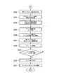
図4,図5,図6,図7は、ロボット1がターゲットの物体をつかんでプレース位置まで運ぶ動作を制御するための処理の手順を示すフローチャートである。図4,図5,図6,図7は、結合子によって結合された1つのフローチャートである。以下、このフローチャートに沿って、処理手順について説明する。[6. Processing procedure]
4, FIG. 5, FIG. 6, and FIG. 7 are flowcharts showing a processing procedure for controlling an operation in which the robot 1 grabs a target object and carries it to a place position. 4, FIG. 5, FIG. 6, and FIG. 7 are one flowchart connected by a coupler. Hereinafter, the processing procedure will be described with reference to this flowchart.
まず図4のステップS1において、制御部40は、第1カメラ14Lおよび14Rが撮影した画像を取得する。
次に、ステップS2において、制御部40は、ステップS1で取得した各画像のアラウンドビュー処理(座標変換処理)を行い、それらの画像を合成する処理を行う。これにより、制御部40は、ロボット1の周辺の平面図画像を生成する。
次に、ステップS3において、制御部40は、ステップS2で生成した平面図画像内に含まれる台座11を認識する。台座11を認識するために、制御部40は、予め台座11の画像としての特徴を学習しておく。あるいは、制御部40は、台座11の所定の箇所に付けられた標識(特徴的な画像)を認識することにより台座11を認識する。あるいは、制御部40は、各々の第1カメラ(14Lや14R)で撮影した画像における台座11のおよその座標位置を予め取得しておく。制御部40は、台座11を認識するために、ここに例示した方法の複数を組み合わせて用いてもよい。First, in step S1 of FIG. 4, the
Next, in step S2, the
Next, in step S3, the
次に、ステップS4において、制御部40は、前述の方法により、ロボット1が有する各アーム(第1アーム15、第2アーム16)の向きや角度、支柱12の向き(回転軸を中心とした回転の向き)、および先端部31の位置と向きを計算し、記憶する。なお、制御部40は、各アームの向きや、先端部31の位置および向きを、台座11を基準として相対的な向きあるいは位置として計算する。ステップS3において平面図画像内の台座11が認識されているため、制御部40は、平面図画像の座標を基準として各アームの向きや、先端部31の位置および向きを把握できる。
次に、ステップS5において、制御部40は、操作の対象とするターゲット(物体や場所)を平面図画像内で認識する。制御部40は、前述の通り、予め取得しているターゲットの特徴を用いて平面図画像内のターゲットを認識できる。また、制御部40が、ユーザーによる指定(GUIからの指定)によりターゲットを認識するようにしてもよい。Next, in step S4, the
Next, in step S5, the
次に、ステップS6において、制御部40は、アームおよび先端部31の移動計画を行う。制御部40は、既に把握しているアームおよび先端部31の現在位置と、ターゲットの位置とに基づき、アームおよび先端部31の移動を計画する。例えば、制御部40は、先端部31をx−y平面(設置面5)と平行に移動させることによりターゲット位置の上部に持っていくよう、アームの動きを計画する。このとき、制御部40は、直交座標(x軸およびy軸)を用いた計算を行ってもよいし、台座11の所定の位置を極とする極座標を用いた計算を行ってもよい。なお、「ターゲット位置の上部」とは、必ずしもターゲットの真上の位置(x−y平面におけるターゲット位置から、x−y平面と垂直に上方に移動させた位置)でなくてもよい。例えば、先端部31に取り付けられた第2カメラ34がターゲットを認識しやすい位置や、フィンガー33がターゲットを操作しやすい位置を「ターゲット位置の上部」としてもよい。
次に、ステップS7において、制御部40は、ステップS6で立てた計画に基づき、アームを移動させる制御を行う。これにより、何らかの不測の状況(例えば、ロボット1自体が持ち上げられてその位置が変えられてしまうなど)が生じない限り、先端部31は、ターゲット位置の上方に移動する。Next, in step S6, the
Next, in step S7, the
次に、ステップS8において、制御部40は、第2カメラ34で撮影した画像を取得する。
次に、ステップS9において、制御部40は、ステップS8で取得した画像を解析し、その画像内におけるターゲットを認識する。また、制御部40は、その画像内におけるターゲットの位置を把握する。本ステップでターゲットの認識を行うのは、ステップS6で立てた移動計画で目標としたターゲット位置の上部に実際に先端部31が来ているか否かをチェックするためである。Next, in step S8, the
Next, in step S9, the
次に、ステップS10において、制御部40は、ステップS9で把握したターゲットの位置(第2カメラ34で撮影した画像内の位置)に基づき、先端部31の現在位置がターゲットに対して適切であるか否かを判断する。先端部31の位置(アームの位置)が適切である場合(ステップS10:YES)には、図5のステップS12に進む。先端部31の位置が適切ではない場合(ステップS10:NO)には、位置を補正するためにS11に進む。
ステップS11に進んだ場合には、制御部40は、ターゲットが第2カメラの視野内に存在するか否かを判定する。言い換えれば、制御部40は、ステップS8で第2カメラ34から取得した画像内にターゲットが存在していたか否かを判定する。ターゲットが第2カメラの視野内である場合(ステップS11:YES)には、アームの再移動による位置の補正を行うために、ステップS6に進む。ターゲットが第2カメラの視野内ではない場合(ステップS11:NO)には、第1カメラによるターゲットの捕捉からやり直すために、ステップS1に戻る。Next, in step S10, the
When the process proceeds to step S11, the
次に、図5に示す処理を説明する。
ステップS12に進んだ場合、制御部40は、レーザー照射部32がレーザーを照射するよう制御する。
次に、ステップS13において、レーザーが照射されている状態で、第2カメラ34が撮影を行う。制御部40は、第2カメラ34からその画像を取得する。
次に、ステップS14において、制御部40は、ステップS13で取得した画像に基づいて、ターゲットの立体構造を推定する処理を行う。ここで具体的には、前述の通り、制御部40は、ターゲットである物体までの距離や、物体の向きなどを推定する処理を行う。Next, the process shown in FIG. 5 will be described.
When the process proceeds to step S12, the
Next, in step S13, the
Next, in step S14, the
次に、ステップS15において、制御部40は、ステップS14の処理によってターゲットの立体構造が推定可能であったか否かを判定する。立体構造が推定可能であった場合(ステップS15:YES)には、ステップS17に進む。立体構造が推定可能ではなかった場合(ステップS15:NO)には、先端部31の位置を変えて再度画像取得を行うためにステップS16に進む。
次に、ステップS16に進んだ場合、制御部40は、アームを少し下げるよう制御する。言い換えれば、制御部40は、先端部31の位置が今までよりも少し(所定量)下の位置になるよう、関節を動かす制御を行う。これにより、先端部31はターゲットである物体により近づくため、より良い画像(第2カメラ34による画像)を取得できるようになることが期待される。ステップS16の次には、ステップS12に戻る。Next, in step S15, the
Next, when the process proceeds to step S16, the
次に、ステップS17において、制御部40は、ステップS14における処理で推定された結果に基づいて、ターゲットである物体をつかむための高さと角度とを算出する。この算出結果に基づいて、制御部40は、ターゲットである物体をつかむ位置まで先端部31を移動させるための、各関節の変位量を求める。
次に、ステップS18において、制御部40は、ステップS17で求めた結果に基づいて各関節の動きを制御し、アームを動かすことによって先端部31を所望の位置に移動させる。そして、制御部40は、フィンガー33がターゲットの物体をつかむ動作をするよう制御する。Next, in step S17, the
Next, in step S18, the
次に、ステップS19において、制御部40は、第2カメラ34が撮影した画像を取得し、その画像を解析する。制御部40は具体的には、フィンガー33がターゲットの物体をうまくつかめているか否かを解析する。
次に、ステップS20において、制御部40は、ステップS19における解析結果に基づいて、ターゲットをつかむことに成功しているか否かを判定する。ターゲットをつかむことに成功している場合(ステップS20:YES)、ステップS22に進む。ターゲットをつかむことに成功していない場合(ステップS20:NO)、ステップS21に進む。
ステップS21に進んだ場合、制御部40は、先端部31を上げる(ターゲットの物体から離れる)よう、アームを移動させたうえで、再度ターゲットをつかむための一連の手順を実行するためにステップS12の処理に戻る。Next, in step S19, the
Next, in step S20, the
When the process proceeds to step S21, the
ステップS22に進んだ場合、フィンガー33がターゲットの物体をつかんだ状態で、制御部40は、先端部31を上げるようアームを移動させる制御を行う。
When the process proceeds to step S22, the
図6のステップS23からの処理は、ロボット1がつかんだ物体をプレース位置まで運んで置く動作を行うための制御である。
ステップS23において、制御部40は、第1カメラ14が撮影した画像を取得する。
次に、ステップS24において、制御部40は、ステップS23で取得した画像に基づいて、座標変換処理(アラウンドビュー処理)および合成処理を行い、平面図画像を生成する。
次に、ステップS25において、制御部40は、ステップS24で生成した平面図画像上で、つかんでいる物体を置くためのプレース位置を認識する。具体的には、制御部40は、予め取得しているプレース位置の特徴を用いて自動的にプレース位置を認識する。あるいは、制御部40は、GUIによりユーザーが指定するプレース位置の情報を把握する。あるいは、制御部40は、台座11を基準としたときのプレース位置の座標情報を予め与えられていてもよい。The process from step S23 in FIG. 6 is a control for carrying the object grasped by the robot 1 to the place position and placing it.
In step S23, the
Next, in step S24, the
Next, in step S25, the
次に、ステップS26において、制御部40は、先端部31を現在位置からプレース位置の上部まで移動させる計画を作成する。ここでの移動は、先端部31をx−y平面に平行な方向に移動させるものである。具体的には、制御部40は、各関節を変位させる量を求める。
次に、ステップS27において、制御部40は、ステップS26で作成した計画に基づいて、先端部31を移動させる制御を行う。Next, in step S26, the
Next, in step S27, the
次に、ステップS28において、制御部40は、第2カメラ34で撮影した画像を取得する。
次に、ステップS29において、制御部40は、ステップS28で取得した画像に基づいて、プレースの位置を認識する処理を行う。ここでも、制御部40は、予め取得しているプレース位置の特徴を用いて自動的にプレース位置を認識する。
次に、ステップS30において、制御部40は、アームおよび先端部31の位置が、ステップS29で認識したプレースの位置に対して適切であるか否かを判定する。アームおよび先端部31の位置が適切である場合(ステップS30:YES)には、図7のステップS32に進む。アームおよび先端部31の位置が適切はない場合(ステップS30:NO)には、ステップS31に進む。
ステップS31に進んだ場合、制御部40は、ステップS29での認識処理の結果として、プレースの位置が第2カメラの視野内であったか否かを判定する。言い換えれば、制御部40は、ステップS28で第2カメラ34から取得した画像内に、プレースが写っているか否かを判定する。
プレースの位置が第2カメラの視野内である場合(ステップS31:YES)には、先端部31を再度移動させるためにステップS26に移る。
プレースの位置が第2カメラの視野内ではない場合(ステップS31:NO)には、第1カメラ14で広範囲の画像を撮影しなおす処理からやり直すためにステップS23に移る。Next, in step S28, the
Next, in step S29, the
Next, in step S30, the
When the process proceeds to step S31, the
When the position of the place is within the field of view of the second camera (step S31: YES), the process proceeds to step S26 in order to move the
If the position of the place is not within the field of view of the second camera (step S31: NO), the process proceeds to step S23 in order to start over from the process of retaking a wide range of images with the first camera 14.
そして、図7のステップS32に進んだ場合、制御部40は、アームを下げて先端部31がプレースの位置に近付くようにする。
そして、ステップS33において、制御部40は、フィンガー33がつかんでいた対象物体を離すように制御することによって、その対象物体(ターゲット)をプレースに格納する。
ステップS33で、ロボット1がターゲットをつかみプレースに格納するまでの一連の動きの制御の全体(図4から図7までのフローチャート)を終了する。Then, when the process proceeds to step S32 in FIG. 7, the
Then, in step S33, the
In step S33, the entire control of a series of movements (flow charts from FIG. 4 to FIG. 7) until the robot 1 grabs the target and stores it in the place is completed.
以上説明したように、このフローチャートに示した手順では、第1カメラおよび第2カメラは、互いに異なるフェーズにおいて対象物を撮影し、制御部は、それらのフェーズごとに、第1カメラが撮影した第1画像に基づいてアームの向きを変えるよう制御し、第2カメラが撮影した第2画像に基づいてアームの向きを変えるよう制御する。 As described above, in the procedure shown in this flowchart, the first camera and the second camera photograph the object in different phases, and the control unit captures the object by the first camera in each of the phases. It is controlled to change the direction of the arm based on one image, and is controlled to change the direction of the arm based on the second image taken by the second camera.
以上説明したように、本実施形態によると、複数の第1カメラ14が広域の画像を撮影する。制御部40は、第1カメラで撮影された画像を座標変換し平面図の部分画像とする(アラウンドビュー処理)。また、制御部40は、それらの複数の部分画像を合成して1枚の平面図画像を生成する。複数の画像から平面図画像を合成することにより、ロボット1自体(台座11等)による死角のない平面図画像を取得できる。つまり、制御部40は、ロボット1の周辺の状況を把握することができる。また、制御部40は、平面図画像内における台座11を認識する。これにより、制御部40は、周辺の状況と、ロボット1自身の台座の位置および向きと、各アームの向きおよび先端部31の位置および向きをすべて関連付けて把握することができる。即ち、制御部40は、ロボット1および周辺の位置情報を正確に把握することができる。つまり、例えばユーザーがロボット1を持ち運んだり向きを変えたりした場合にも、ロボット1の制御部40は、周辺(作業環境)に固定設置されたカメラ等に頼ることなく、自己の位置を自動的に把握することができる。即ち、ロボット1の位置等を変えても、そのための再調整の操作を行う必要がない。
As described above, according to the present embodiment, the plurality of first cameras 14 capture a wide area image. The
また、本実施形態によると、先端部31に固定された第2カメラで撮影した画像を用いて、制御部40が操作対象物体や場所等を認識する。つまり、ロボットとカメラとの位置関係を設定する操作を行う必要がない。
Further, according to the present embodiment, the
また、本実施形態によると、ロボット1は、比較的広域を撮影する第1カメラと、アームの先端部31に固定設置された第2カメラとを併用する。これにより、ロボット1は、周辺全体を見渡して把握しつつ、先端の操作対象物体等を細かく認識することが可能となる。つまり、ロボット1は正確な作業を行えるようになる。加えて、第1カメラ14の解像度や精度は、遠距離から対象物の存在する位置が認識できる程度のものであればよい。また、第2カメラ34の解像度や精度は、近距離から対象物の形状を認識できる程度のものであればよい。これら2種類のカメラの使い分けにより、必ずしも、精度や解像度が特別に高いカメラを用いずともロボット1は正確な作業を実施できる。カメラモジュールの選択の自由度が広がる。
操作対象物体等に近づいて詳細な状況を把握することと、全体を広く見渡すこととは、背反する要求であるが、本実施形態のロボット1は、固定カメラを設置することなく、それら両方の要求を満たすことが可能となる。
また、対象物体がカメラの視野の外に出てしまい、ロボット1が対象物体を見失った場合でも、アームを動かすことにより、カメラがアームとともに動き再度対象物体を捉えることができる。死角が発生した場合でもアームの動きによって解消できる可能性があるため、カメラを固定する際の配置や角度に自由度がある。
以上のように、本実施例によれば、比較的小型のロボットの可搬性や機動性を損なうことなく、ロボット動作の自動化を実現することができる。Further, according to the present embodiment, the robot 1 uses a first camera that captures a relatively wide area and a second camera that is fixedly installed at the
It is a contradictory requirement to get close to the object to be operated and grasp the detailed situation and to have a wide view of the whole, but the robot 1 of the present embodiment has both of them without installing a fixed camera. It becomes possible to meet the demand.
Further, even if the target object goes out of the field of view of the camera and the robot 1 loses sight of the target object, by moving the arm, the camera moves together with the arm and can catch the target object again. Even if a blind spot occurs, it may be eliminated by the movement of the arm, so there is a degree of freedom in the arrangement and angle when fixing the camera.
As described above, according to the present embodiment, it is possible to realize the automation of the robot operation without impairing the portability and maneuverability of the relatively small robot.
[第2実施形態]
次に、第2実施形態について説明する。第2実施形態の特徴は、先端部31に複数のレーザー照射部が設けられており、それら複数のレーザー照射部のうちの少なくとも1つは、他のレーザー照射部とは異なる方向にレーザーを照射することである。[Second Embodiment]
Next, the second embodiment will be described. The feature of the second embodiment is that a plurality of laser irradiation portions are provided at the
図8は、本実施形態による特徴的部分である先端部31bの詳細な構成を示す概略図(側面図)である。また、同図は、本実施形態での複数のレーザー照射部の配置と、レーザーが照射される面との関係を示している。図示するように、先端部31bは、複数のレーザー照射部を備える。具体的には、先端部31bは、レーザー照射部32−1および32−2を有している。また、先端部31bは、第2カメラ34を備えている。なお、先端部31bに備えられているフィンガー33をこの図では省略している。
FIG. 8 is a schematic view (side view) showing a detailed configuration of the
図示するように、レーザー照射部32−1が照射する方向(破線Aで示す)と、レーザー照射部32−2が照射する方向(破線Bで示す)とは、異なる。つまり、複数のレーザー照射部のうちの少なくとも1つは、他のレーザー照射部とは異なる方向にレーザーを照射する。これら2つのレーザー照射部32−1および32−2は、設置面5に投射される。このとき、先端部31bと設置面5との距離に応じて、この2本のレーザーによって照射されるポイント間の設置面上での距離が異なる。
As shown in the figure, the direction of irradiation by the laser irradiation unit 32-1 (indicated by the broken line A) and the direction of irradiation by the laser irradiation unit 32-2 (indicated by the broken line B) are different. That is, at least one of the plurality of laser irradiation units irradiates the laser in a direction different from that of the other laser irradiation units. These two laser irradiation units 32-1 and 32-2 are projected onto the
図9および図10は、図8に示したレーザー照射部がそれぞれ設置面5に投射するパターンの例を示す概略図である。図9は、レーザー照射部と設置面とが、ある距離だけ離れている場合の、設置面5に投射されるパターンを示す。図10は、レーザー照射部が図9のときよりも設置面に近づいた場合の、設置面5に投射されるパターンを示す。
図9において、上側の十字型(斜めの十字型)は、レーザー照射部32−2によって照射されているパターンである。また、下側の十字型(縦線および横線からなる十字型)は、レーザー照射部32−1によって照射されているパターンである。
図10において、破線で示す十字型は、図9において上側の十字型が投射されていた位置を示す。また、2個の実線による十字型のうち、上側の十字型(斜めの十字型)は、レーザー照射部32−2によって照射されているパターンである。また、下側の十字型(縦線および横線からなる十字型)は、レーザー照射部32−1によって照射されているパターンである。
このように、図9の場合と図10の場合とで、投射されるパターン間の距離が異なる。言い換えれば、投射されるパターンにおける両者間の距離を測定することにより、レーザー照射部の位置から投射面の位置までの距離を推定することができる。9 and 10 are schematic views showing an example of a pattern in which the laser irradiation unit shown in FIG. 8 projects onto the
In FIG. 9, the upper cross shape (diagonal cross shape) is a pattern irradiated by the laser irradiation unit 32-2. The lower cross shape (cross shape composed of vertical and horizontal lines) is a pattern irradiated by the laser irradiation unit 32-1.
In FIG. 10, the cross shape shown by the broken line indicates the position where the upper cross shape is projected in FIG. 9. Of the two solid crosses, the upper cross (diagonal cross) is the pattern irradiated by the laser irradiation unit 32-2. The lower cross shape (cross shape composed of vertical and horizontal lines) is a pattern irradiated by the laser irradiation unit 32-1.
As described above, the distance between the projected patterns is different between the case of FIG. 9 and the case of FIG. In other words, the distance from the position of the laser irradiation unit to the position of the projection surface can be estimated by measuring the distance between the two in the projected pattern.
図11は、先端部31bの詳細な構成を示す概略図(側面図)である。また、同図は、本実施形態での複数のレーザー照射部の配置と、レーザーが照射される面との関係を示している。この図を参照しながら、次に、先端部31bと設置面5との間の距離を測定する方法を説明する。
FIG. 11 is a schematic view (side view) showing a detailed configuration of the
図示するように、先端部31bには、2個のレーザー照射部32−1および32−2が設けられている。レーザー照射部32−1とレーザー照射部32−2との光源間の距離はxである。レーザー照射部32−1からは真下に(設置面5に対して垂直に)レーザー光(光線A)が照射されるようになっている。また、レーザー照射部32−2からは斜め方向に、つまり水平面(例えば先端部31bの底面)から下方向にθの角度の方向に、レーザー光(光線B)が照射されるようになっている。レーザー照射部32−1および32−2の位置およびレーザー照射方向が変わらない限り、xおよびθの値は不変である。
As shown in the figure, the
先端部31bに取り付けられた第2カメラ34は、下方向を、即ち設置面5の方向を撮影する。制御部40は、第2カメラ34が撮影した画像を取得し、次のように、先端部31bの底面(ロボットの先端部)から設置面5までの距離を求める。つまり、制御部40は、撮影された画像を基にスケーリング処理を行い、光線Aの設置面5への照射位置のポイント(レーザー照射部32−1からの照射)と、光線Bの設置面5への照射位置のポイント(レーザー照射部32−2からの照射)との距離を求める。その距離をdとする。また、既に述べたように両光源間の距離はxであるので、先端部31bの底面から設置面5までの距離zを、制御部40は、次の式により計算する。ここで、tan()は正接関数である。
z=(x−d)・tan(θ)The
z = (x−d) · tan (θ)
以上のように、先端部31bに、真下に(垂直に)照射するように取り付けられたレーザー照射部32−1と、斜めに(角度θで)照射するように取り付けられたレーザー32−2とが、それぞれ設置面5にレーザー光を照射する。そして、第2カメラ34が撮影した画像を基に、制御部40は、設置面5に照射された2点のレーザー光を認識する。制御部40はこの2点間の距離に基づいて先端部31bの底面から設置面5までの距離(高さ)を測定する。これにより、制御部40は、フィンガー33を用いて対象物をつかむ際の高さ方向の移動量を求めることができる。
As described above, the laser irradiation unit 32-1 attached to the
なお、次のような変形例によって制御部40が先端部31bの高さを測定するようにしてもよい。例えば、レーザー照射部32−1を先端部31bに取り付ける際、照射方向が真下(先端部31bの底面に対して垂直)でなくてもよい。レーザー照射部32−1の照射方向が斜め(但し、既知の角度での照射)であっても、適宜、制御部40は高さを算出することができる。また、例えば、設置面5に照射したレーザー光を認識するために、第2カメラ34で撮影した画像の代わりに、第1カメラ14Lや14Rで撮影した画像を用いてもよい。
The height of the
また、レーザー照射部32−1および32−2が照射するレーザー光が交差後に設置面5に照射されてもよい。
図12は、2本のレーザー光が交差した後に設置面に照射される例を示す先端部31bの概略図(側面図)である。図示するように、レーザー照射部32−1は、真下に(設置面5に対して垂直に)レーザー光(光線A)を照射する。また、レーザー照射部32−2は、先端部31bからの角度θで斜め下方向にレーザー光(光線B)を照射する。光線AとBとは交差した後に、設置面5に照射される。設置面5における照射ポイント間の距離はdである。また、レーザー照射部32−1と32−2との光源間の距離はxである。この場合、制御部40は、光線AおよびBが交差した後で設置面5に照射されていることを前提として、先端部31bの底面から設置面5までの距離zを、次の式により計算する。
z=(x+d)・tan(θ)Further, the
FIG. 12 is a schematic view (side view) of the
z = (x + d) · tan (θ)
以上説明した通り、本実施形態によれば、制御部40は対象物をつかむ位置を自動的に算出できるため、ロボットの設置場所を変更した場合にも、対象物をつかむ位置を設定する操作を行う必要がない。つまり、小型のロボットの可搬性を損なうことなく、ロボット動作の自動化を実現できる。
As described above, according to the present embodiment, the
[第3実施形態]
次に、第3実施形態について説明する。第3実施形態の特徴は、ロボットが自律移動部を備えている点である。これにより、ロボットは、設置面に固定して置かれるだけではなく、広範囲に移動することもできる。[Third Embodiment]
Next, the third embodiment will be described. The feature of the third embodiment is that the robot is provided with an autonomous moving unit. As a result, the robot can be moved not only fixedly on the installation surface but also over a wide range.
図13は、本実施形態によるロボット2の移動動作の概略を示す概略図である。図示する例では、ロボット2aは移動前の位置を表し、ロボット2bは移動後の位置を表す。同図に示すように、ロボット2が稼働する場所には、レール201が敷設されている。またレール201の近くに、ロボット2が操作対象とする対象物202が置かれている。ロボット2は、例えばモーターによって車輪(不図示)を駆動することにより、レール201に沿って前後方向に移動することができる。あるいは、ロボット2は、レール201上だけでなく、車輪(例えば4輪)で平面上を任意の方向に自由に移動できるようになっていてもよい。ロボット2の制御部40が車輪を駆動するよう制御することにより、ロボット2は対象物202に近付くことができる。また、ロボット2は、状況に応じて、所望の位置に移動することができる。
FIG. 13 is a schematic view showing an outline of the moving operation of the
なお、上記の、車輪およびそれらの車輪を駆動する機構を、「自律移動部」と呼ぶ。即ち、自律移動部は、ロボットが設置面を自律移動するための機能である。自律移動部は、制御部40によって制御される。自動移動部が機能することにより、アームが届かない位置に対象物やプレースがある場合や、第1カメラ14から目的物やプレースが視認できない場合にも、ロボット2は、自律的に所望の対象物あるいはプレースの近傍に移動することができる。
The wheels and the mechanism for driving those wheels are referred to as "autonomous moving units". That is, the autonomous movement unit is a function for the robot to autonomously move on the installation surface. The autonomous movement unit is controlled by the
図14,図15,図16,図17は、本実施におけるロボット2の処理の手順を示すフローチャートである。このフローチャートは、ロボット2がターゲットの物体をつかんでプレース位置まで運ぶ動作を制御するための処理の手順を示すものである。図14,図15,図16,図17は、結合子によって結合された1つのフローチャートである。以下、このフローチャートに沿って、処理手順について説明する。
14, FIG. 15, FIG. 16, and FIG. 17 are flowcharts showing the processing procedure of the
図14のステップS101からS105までの処理は、それぞれ対応する図4のステップS1からS5までの処理と同様のものである。
ステップS106において、制御部40は、ターゲットにアームが届く範囲にあるか否かを判定する。なお、ターゲットの認識処理(ステップS105)を行った結果としてターゲットが見つからない場合も、制御部40は、ターゲットにアームが届く範囲にはないと判断する。ターゲットにアームが届く範囲にあると判断した場合(ステップS105:YES)、ステップS108に進む。ターゲットにアームが届く範囲にないと判断した場合(ステップS105:NO)、ロボットを移動させてターゲットを認識しなおすために、ステップS107に進む。The processes from steps S101 to S105 in FIG. 14 are the same as the corresponding processes from steps S1 to S5 in FIG.
In step S106, the
ステップS107に進んだ場合、制御部40は、自律移動部を制御し、ロボット2自身を移動させる。具体的には、ロボット2の車輪を動かすことにより、ロボット2を所定の位置まで移動させる。本ステップの終了後は、ステップS101に戻って処理を続ける。
When the process proceeds to step S107, the
ステップS108に進んだ場合、ステップS108からS111までにおいて、制御部40は、アームを移動させる制御を行い、第2カメラ34から取得した画像に基づいてターゲットの位置を認識する。この処理は、図4のステップS6からS9までの処理と同様のものである。
次に、ステップS112において、制御部40は、図4のステップS10と同様の判断を行い、判断結果に応じて分岐する。即ち、先端部31の位置(アームの位置)が適切である場合(ステップS112:YES)には、図15のステップS114に進む。先端部31の位置が適切ではない場合(ステップS112:NO)には、位置を補正するためにS113に進む。
ステップS113に進んだ場合には、制御部40は、図4のステップS11と同様の判断を行い、判断結果に応じて分岐する。即ち、ターゲットが第2カメラの視野内である場合(ステップS113:YES)には、アームの再移動による位置の補正を行うために、ステップS108に進む。ターゲットが第2カメラの視野内ではない場合(ステップS113:NO)には、第1カメラによるターゲットの捕捉からやり直すために、ステップS101に戻る。When the process proceeds to step S108, in steps S108 to S111, the
Next, in step S112, the
When the process proceeds to step S113, the
図15のステップS114からS124までの処理は、それぞれ、図5のステップS12からS22までの処理と同様のものである。図15のステップS124の処理が終了すると、ステップS125に移る。 The processes of steps S114 to S124 of FIG. 15 are the same as the processes of steps S12 to S22 of FIG. 5, respectively. When the process of step S124 of FIG. 15 is completed, the process proceeds to step S125.
図16のステップS125からS127までの処理は、それぞれ、図6のステップS23からS25までの処理と同様のものである。
次に、ステップS128において、制御部40は、プレースにアームが届く範囲にあるか否かを判定する。なお、プレースの認識処理(ステップS127)を行った結果としてプレースが見つからない場合も、制御部40は、プレースにアームが届く範囲にはないと判断する。プレースにアームが届く範囲にあると判断した場合(ステップS128:YES)、ステップS130に進む。プレースにアームが届く範囲にないと判断した場合(ステップS128:NO)、ロボットを移動させてターゲットを認識しなおすために、ステップS129に進む。The processes from steps S125 to S127 in FIG. 16 are the same as the processes from steps S23 to S25 in FIG. 6, respectively.
Next, in step S128, the
ステップS129に進んだ場合、制御部40は、自律移動部を制御し、ロボット2自身を移動させる。具体的には、ロボット2の車輪を動かすことにより、ロボット2を所定の位置まで移動させる。本ステップの終了後は、ステップS125に戻って処理を続ける。
When the process proceeds to step S129, the
ステップS130に進んだ場合、ロボット2は、ステップS130からS135までの処理を行う。ステップS130からS135までの処理は、図6のステップS26からS31までの処理と同様のものである。
ステップS134において、制御部40がアーム位置はプレースに対して適切であると判定した場合(ステップS134:YES)、図17のステップS136に移る。ステップS134において、制御部40がアーム位置はプレースに対して適切ではないと判定した場合(ステップS134:NO)、テップS135に移る。ステップS135において図6のステップS31と同様の判定を行うことにより、ステップS125またはS130のいずれか適切な側の処理に戻る。When the process proceeds to step S130, the
When the
図17のステップS136に進んだ場合、ロボット2は、ステップS136およびS137の処理を行う。ステップS136およびS137の処理は、それぞれ、図7のステップS32およびS33の処理と同様のものである。
ステップS137の処理が終了すると、本フローチャート全体の処理手順を終了する。When the process proceeds to step S136 of FIG. 17, the
When the process of step S137 is completed, the process procedure of the entire flowchart is completed.
以上のように、ロボット2が自律移動した場合には、その移動先において、ロボット2は、第1カメラを用いて周囲の画像を取得し直し、座標変換等を行って合成済画像を生成する。
このとき、制御部40は、平面画像(合成済画像)中の台座11の位置に基づいて、上記移動先でのアームの先端と設置面との座標関係を認識することができる。As described above, when the
At this time, the
以上説明したように、本実施形態によれば、任意の場所に移動した後でも、第1カメラおよび第2カメラは、必ずロボットの周囲を観測可能な位置に設置されており、ターゲットやプレースの位置を認識することができる。移動型ロボットの自律移動性を損なうことなく、ロボットの動作の自動化が可能となる。 As described above, according to the present embodiment, the first camera and the second camera are always installed at positions where the surroundings of the robot can be observed even after moving to an arbitrary place, and the target or the place can be used. The position can be recognized. It is possible to automate the movement of the mobile robot without impairing the autonomous mobility of the mobile robot.
[第4実施形態]
次に、第4実施形態について説明する。第4実施形態の特徴は、第1カメラと第2カメラを同時に使用しながらロボットを操作することである。つまり、本実施形態では、制御部40の制御により、第1カメラ14L,14Rおよび第2カメラ34は、同時に対象物を撮影する。また、制御部40は、第1カメラ14L,14Rおよび第2カメラ34によって同時にそれぞれ撮影された画像に基づいて、アームの位置や向きを変えるよう制御する。[Fourth Embodiment]
Next, the fourth embodiment will be described. The feature of the fourth embodiment is to operate the robot while using the first camera and the second camera at the same time. That is, in the present embodiment, under the control of the
図18,図19,図20は、本実施におけるロボット3の処理の手順を示すフローチャートである。このフローチャートは、ロボット3がターゲットの物体をつかんでプレース位置まで運ぶ動作を制御するための処理の手順を示すものである。図18,図19,図20は、結合子によって結合された1つのフローチャートである。以下、このフローチャートに沿って、処理手順について説明する。
18, FIG. 19, and FIG. 20 are flowcharts showing the processing procedure of the
図18のステップS201からS207までの処理は、それぞれ、図4のステップS1からS7までの処理と同様である。
次に、ステップS208において、制御部40は、第1カメラ14Lおよび14Rと、第2カメラ34との両方が、それぞれ撮影を行うよう制御する。制御部40は、第1カメラ14Lおよび14Rと、第2カメラ34とから、画像を取得する。つまり、制御部40は、第1カメラ14L,14Rおよび第2カメラ34を同時に使用する。The processes from steps S201 to S207 in FIG. 18 are the same as the processes from steps S1 to S7 in FIG. 4, respectively.
Next, in step S208, the
次に、ステップS209において、制御部40は、第1カメラ14L,14Rおよび第2カメラ34から取得した画像を用いて、ターゲットの位置を認識する。第1カメラ14L,14Rと第2カメラ34の両方を使うことにより、例えば第2カメラ34の視野内にターゲットがない場合でも、第1カメラ14L,14Rで撮影した画像を基に合成した合成済画像に基づいて、制御部40は、どの方向にターゲットがあるかを認識することができる。
Next, in step S209, the
次に、ステップS210において、制御部40は、アームの先端部31の位置がターゲットに対して適切(例えば、先端部31がターゲットの上方にあり、ターゲットに近づくことができる)か否かを判定する。アーム位置がターゲットに対して適切である場合(ステップS210:YES)には、図19のステップS211に進む。アーム位置が適切ではない場合(ステップS210:NO)には、アームの移動を再度行うためにステップS206に戻る。
Next, in step S210, the
図19のステップS211からステップS221までの処理は、それぞれ、図5のステップS12からステップS22までの処理と同様である。 The processes from step S211 to step S221 in FIG. 19 are the same as the processes from step S12 to step S22 in FIG. 5, respectively.
次に、図20のステップS222からステップS226までの処理は、それぞれ、図6のステップS23からステップS27までの処理と同様である。
次に、ステップS227において、制御部40は、第1カメラ14Lおよび14Rと、第2カメラ34との両方が、それぞれ撮影を行うよう制御する。制御部40は、第1カメラ14Lおよび14Rと、第2カメラ34とから、画像を取得する。
次に、ステップS228において、制御部40は、第1カメラ14L,14Rおよび第2カメラ34から取得した画像を用いて、プレースの位置を認識する。第1カメラ14L,14Rと第2カメラ34の両方を使うことにより、例えば第2カメラ34の視野内にプレースがない場合でも、第1カメラ14L,14Rで撮影した画像を基に合成した合成済画像に基づいて、制御部40は、どの方向にプレースがあるかを認識することができる。Next, the processes from step S222 to step S226 in FIG. 20 are the same as the processes from step S23 to step S27 in FIG. 6, respectively.
Next, in step S227, the
Next, in step S228, the
次に、ステップS229において、制御部40は、アームの先端部31の位置がプレースに対して適切か否かを判定する。アーム位置がプレースに対して適切である場合(ステップS229:YES)には、ステップS230に進む。アーム位置が適切ではない場合(ステップS229:NO)には、アームの移動を再度行うためにステップS225に戻る。
次のステップS230およびステップS231の処理は、それぞれ、図7のステップS32およびステップS33の処理と同様である。
ステップS231の処理が終わると、ロボット3は、このフローチャートの処理をすべて終了する。Next, in step S229, the
The processing of the next steps S230 and S231 is the same as the processing of steps S32 and S33 of FIG. 7, respectively.
When the process of step S231 is completed, the
以上のように、本実施形態では、制御部40は、第1カメラと第2カメラとを同時に使用してターゲットの位置やプレースの位置を認識する。
これにより、例えば第2カメラ34の視野内にターゲットやプレースがない場合でも、第1カメラ14L,14Rによりどの方向にターゲットやプレースがあるかを認識できる。よって、制御部40は、より早く、ターゲットやプレースの位置にアームのセンタ部を移動させるよう制御することができる。
つまり、本実施例によれば、比較的小型のロボットの可搬性や機動性を損なうことなく、ロボット動作の自動化を実現することができる。As described above, in the present embodiment, the
Thereby, for example, even if there is no target or place in the field of view of the
That is, according to this embodiment, it is possible to realize automation of robot operation without impairing the portability and maneuverability of a relatively small robot.
[第5実施形態]
次に、第5実施形態について説明する。第5実施形態によるロボット4の特徴は、レーザー照射部が照射した設置面を撮影し、得られた画像に基づいて設置面の段差を把握・測定することである。[Fifth Embodiment]
Next, the fifth embodiment will be described. The feature of the robot 4 according to the fifth embodiment is that the installation surface irradiated by the laser irradiation unit is photographed, and the step difference of the installation surface is grasped and measured based on the obtained image.
図21は、設置面が段差を有する場合のロボットの動作環境を示す斜視図である。図示するように、設置面5は段差を有している。その段差の上側の段が5Uであり、下側の段が5Lである。ロボット4の先端部31に設けられたレーザー照射部32は、図示する例では、十字型のパターンを形成するようにレーザー光線を照射している。第1カメラ14Lおよび14Rは、レーザー光線が照射された、段差を有する設置面を撮影する。撮影された画像に含まれるレーザー光の照射の形状により、制御部40は、設置面に段差が存在することを認識することができる。
FIG. 21 is a perspective view showing the operating environment of the robot when the installation surface has a step. As shown in the figure, the
図22は、段差を有する設置面を第1カメラ14Lおよび14Rで撮影した画像を基に、座標変換および合成の処理を行って得られる合成済画像を示す。同図において、設置面の上側の段は5Uであり、下側の段は5Lである。また破線で示す5Gは段差を表す。
FIG. 22 shows a composited image obtained by performing coordinate transformation and compositing processing on the installation surface having a step based on the images taken by the
図23は、レーザー照射部32による照射方法の一例を示す概略図である。同図は、第1カメラ14Lおよび14Rが複数のタイミングで撮影した画像を合成して得られる合成済画像である。図示する例では、レーザー照射部32は、設置面5の所定の領域に、3行4列の計12個のポイント(P11からP14まで、P21からP24まで、P31からP34まで)を照射する。同図に示す例では、設置面5内の当該領域には段差や凸凹はない。ロボット4は、アームを動かすことによって先端部31に設けられるレーザー照射部32の位置を順次変えながら、第1カメラ14Lおよび14Rによる撮影を行う。つまり、まず、レーザー照射部32がP11の位置を照射しているときに第1カメラ14Lおよび14Rが撮影を行い、次に、レーザー照射部32がP12の位置を照射しているときに第1カメラ14Lおよび14Rが撮影を行い、以下同様に繰り返す。つまり、レーザー照射部32がP11からP34までの12個のポイントを順次照射しながら、各ポイントを照射しているタイミングにおいて第1カメラ14Lおよび14Rが撮影を行う。制御部40は、アームを移動させる制御と、第1カメラ14L,14Rによる撮影を実行するための制御を、順次行う。また、制御部40は、第1カメラ14Lおよび14Rから取得した画像の座標変換と左右合成を行うことにより、各照射タイミングに対応する計12枚の合成済画像を生成する。さらに、制御部40は、各ポイントの照射のタイミングに対応する12枚の画像をすべて重ね合わせる合成処理を行う。その結果、制御部40は、図23に示す12個のポイント(照射されているポイント)を含む1枚の合成済画像を生成する。
FIG. 23 is a schematic view showing an example of the irradiation method by the
図24は、設置面5に段差がある場合に、図23で説明したのと同じ手順で生成した合成済画像を示す概略図である。 図24に示す画像は、図23で説明したのと同じ手順で制御部40がアームを動かすよう制御して、レーザー照射装置32が図23の場合と同じ12種類の位置から順次撮影した画像を合成したものである。但し、図23の画像は段差のない設置面5に照射されたレーザー光を撮影したものであるのに対して、図24の画像は、図21にも示した段差の存在する設置面5を撮影して得られたものである。図示するように、P11からP14までの点は、図23の画像と図24の画像とで同じ位置に現れる。一方、5Gの位置の段差が存在するため、P21からP24まで、およびP31からP34までの点の位置は、図23の画像と図24の画像との間でずれる。
FIG. 24 is a schematic view showing a synthesized image generated by the same procedure as described with reference to FIG. 23 when the
図25,図26,図27は、上記の点の位置のずれが生じる原理を説明するための概略図である。
図25は、ロボット4と、設置面5と、ロボット4による照射のポイントと、そのポイントを含む領域を撮影するカメラ(第1カメラ)との関係を示す側面図である。また、図26は、図25に対応する平面図である。25, 26, and 27 are schematic views for explaining the principle that the positions of the above points are displaced.
FIG. 25 is a side view showing the relationship between the robot 4, the
図示するように、ロボット4が有するレーザー照射部32が、設置面5U上の点であるP21に向けた照射を行う。しかしながら、この例では、段差があることによって、レーザー照射部32から発せられるレーザー光は、面5Uよりも低い位置にある面5L上の点を照射する。第1カメラ14は、この段差を有する面を撮影する。レーザー照射部32はP21に向けた照射を行っているが、第1カメラ14が撮影する画像は、照射されている点はあたかも設置面5上の点であるP21´の位置に存在する点であるかのような画像となる。図26(平面図)を参照すると、面5L上の点であるP21の方向を照射しているレーザー光が、別の点であるP21´の位置を照射しているかのように見える画像が生成される。
As shown in the figure, the
図27は、図25と同様の側面図であり、図25に現れる代表的な位置と位置との間の距離の情報を抽出した側面図である。設置面5を基準としたときのレーザー照射部32の光源の高さをzとする。面6(設置面5よりも下)を基準としたときのレーザー照射部32の光源の高さをz´とする。点P21から第1カメラ14のレンズの主点までの、水平方向の距離をr´とする。また、点P21´から第1カメラ14のレンズの主点までの、水平方向の距離をrとする。rとr´の差であるdが、段差が存在することによるレーザー照射位置のずれ量である。つまり、d=r´−rである。
これらの量を用いて、制御部40は、設置面5と面6との間の高さΔzを、次の式に基づいて算出することができる。
Δz=(z´−z)=d*z´/r=d*z/(r−d)FIG. 27 is a side view similar to that of FIG. 25, and is a side view from which information on the distance between typical positions appearing in FIG. 25 is extracted. Let z be the height of the light source of the
Using these quantities, the
Δz = (z'-z) = d * z'/ r = d * z / (rd)
図25や図26では、P21について説明したが、制御部40は、すべての照射点について同様の計算をすることにより、面の段差の状況や凹凸の状況を把握できる。制御部40は、算出した高さの情報に基づいて、ターゲットをつかんだり離したりする高さを決定することができる。
Although P21 has been described with reference to FIGS. 25 and 26, the
レーザー照射部32による照射パターンは他の形状であってもよい。例えば、照射パターンは、十字型(交わる2本の線分によるもの)であってもよい。
また、レーザー照射部32は、複数の発光部(光源)を有していてもよい。この場合、例えば設置面上の複数のポイントを同時に照射することができる。例えば、レーザー照射部32は、図23に示す12個のポイントのうちのいくつかを同時に照射することができる。また、レーザー照射部32は、時分割で複数のポイントを照射するようにしてもよい。また、照射するポイントの数は12個でなくともよい。また、レーザー照射部32は、必ずしも設置面に対して垂直に照射しなくてもよい。レーザー照射部32が斜め方向に設置面を照射してもよい。The irradiation pattern by the
Further, the
なお、複数のタイミングで撮影した画像を合成(重ね合わせ)して図24に示す画像を生成する代わりに、各タイミングで撮影して得られた合成済画像における照射光の位置にそれぞれ基づいて、設置面の段差あるいは凹凸を算出するようにしてもよい。 Instead of synthesizing (superimposing) the images taken at a plurality of timings to generate the image shown in FIG. 24, the images taken at each timing are based on the position of the irradiation light in the synthesized images obtained at each timing. The step or unevenness of the installation surface may be calculated.
つまり、本実施形態では、制御部40は、レーザー照射部32が、設置面5上の複数の所定位置の方向に光を順次照射するよう、先端部31を移動させながら制御する。また、制御部40は、複数の所定位置の方向にレーザー照射部32が光を照射しているタイミングの各々に対応して複数の合成済画像(平面図画像)を生成する。また、制御部40は、複数の合成済画像(平面図画像)に含まれる所定パターンの光の位置に基づいて、設置面5の段差や凹凸を算出する。この過程において、上記複数のタイミングの合成済画像を重ね合わせる処理を行い、1枚の合成済画像(平面図画像)を生成してもよい。
That is, in the present embodiment, the
以上説明したように、本実施形態によれば、ロボット4は、設置面の段差や起伏を自動的に把握できる。したがって、ロボット4の設置場所を変更した場合でも、ターゲットをつかむ高さなどの位置を設定する操作を行う必要がない。つまり、小型のロボットの可搬性を損なうことなく、ロボット動作の自動化を実現できる。 As described above, according to the present embodiment, the robot 4 can automatically grasp the steps and undulations on the installation surface. Therefore, even if the installation location of the robot 4 is changed, it is not necessary to perform an operation of setting a position such as a height for grasping the target. That is, it is possible to realize automation of the robot operation without impairing the portability of the small robot.
なお、上述した各実施形態におけるロボットの制御部40の少なくとも一部の機能をコンピューターで実現することができる。その場合、この機能を実現するためのプログラムをコンピューター読み取り可能な記録媒体に記録して、この記録媒体に記録されたプログラムをコンピューターシステムに読み込ませ、実行することによって実現しても良い。なお、ここでいう「コンピューターシステム」とは、OSや周辺機器等のハードウェアを含むものとする。また、「コンピューター読み取り可能な記録媒体」とは、フレキシブルディスク、光磁気ディスク、ROM、CD−ROM、DVD−ROM、USBメモリー等の可搬媒体、コンピューターシステムに内蔵されるハードディスク等の記憶装置のことをいう。さらに「コンピューター読み取り可能な記録媒体」とは、インターネット等のネットワークや電話回線等の通信回線を介してプログラムを送信する場合の通信線のように、一時的に、動的にプログラムを保持するもの、その場合のサーバーやクライアントとなるコンピューターシステム内部の揮発性メモリーのように、一定時間プログラムを保持しているものも含んでも良い。また上記プログラムは、前述した機能の一部を実現するためのものであっても良く、さらに前述した機能をコンピューターシステムにすでに記録されているプログラムとの組み合わせで実現できるものであっても良い。
It should be noted that at least a part of the functions of the
本発明は、例えば産業用あるいは娯楽用等、あらゆる種類のロボットに利用することができる。ただし、本発明の利用範囲は、ここに例示したものには限定されない。 The present invention can be used for all kinds of robots, for example, for industrial use or entertainment use. However, the scope of use of the present invention is not limited to those exemplified here.
1,2,2a,2b,3,4 ロボット
5,5L,5U 設置面
11 台座
12 支柱
14,14L,14R 第1カメラ
15 第1アーム
16 第2アーム
21 第1関節
22 第2関節
23 第3関節
31,31b 先端部(ハンド)
32,32−1,32−2 レーザー照射部
33 フィンガー
34 第2カメラ
40 制御部
101 合成済画像(平面図画像)
101L,101R 座標変換済画像(平面図部分画像)
201 レール
202 対象物1,2,2a, 2b, 3,4
32, 32-1, 32-2
101L, 101R coordinate converted image (plan view partial image)
Claims (8)
前記台座に垂直に取り付けられ、垂直軸回りを回転可能な支柱と、
前記支柱に接続され、単数または複数の関節により向きを変えることを可能とするアームと、
前記アームの先端に接続され、前記アームとの向きを変えることを可能とした先端部と、
前記支柱に対して固定された位置に設けられ前記台座自身と前記台座の周辺の前記設置面とを撮影可能とした複数の第1カメラと、
前記複数の第1カメラから第1画像を取得し、前記第1画像を座標変換することによって部分平面図画像を生成し、複数の前記部分平面図の位置合わせを行って合成することによって前記台座の画像を含んだ平面図画像を生成するとともに、前記平面図画像に基づいて前記先端部を所定の位置に移動させるために前記アームの向きを変えるよう制御する制御部と、
を備えるロボット。A pedestal with a point in contact with the installation surface,
A strut that is mounted vertically on the pedestal and can rotate around the vertical axis,
An arm that is connected to the strut and can be turned by a single or multiple joints.
A tip portion connected to the tip of the arm and capable of changing the direction with the arm,
A plurality of first cameras provided at a position fixed to the support column and capable of photographing the pedestal itself and the installation surface around the pedestal, and a plurality of first cameras.
The pedestal is obtained by acquiring a first image from the plurality of first cameras, generating a partial plan view image by coordinate-transforming the first image, and aligning and synthesizing the plurality of the partial plan views. A control unit that generates a plan view image including the image of the above and controls to change the direction of the arm in order to move the tip portion to a predetermined position based on the plan view image.
A robot equipped with.
をさらに備える請求項1に記載のロボット。An irradiation unit that is fixed to the tip and irradiates light having a predetermined pattern in the direction of the installation surface.
The robot according to claim 1.
をさらに備え、
前記制御部は、前記第2カメラから取得する第2画像にも基づいて前記アームの向きを変えるよう制御する、
請求項1または2に記載のロボット。A second camera provided at the tip,
With more
The control unit controls to change the direction of the arm based on the second image acquired from the second camera.
The robot according to claim 1 or 2.
をさらに備えた請求項1に記載のロボット。An autonomous moving unit for autonomously moving on the installation surface,
The robot according to claim 1, further comprising.
前記制御部は、前記第1カメラおよび前記第2カメラによって同時にそれぞれ撮影された画像に基づいて前記アームの向きを変えるよう制御する、
請求項3に記載のロボット。The first camera and the second camera simultaneously photograph an object, and the object is photographed.
The control unit controls to change the direction of the arm based on the images taken by the first camera and the second camera at the same time.
The robot according to claim 3.
前記制御部は、前記フェーズごとに、前記第1カメラが撮影した前記第1画像に基づいて前記アームの向きを変えるよう制御し、前記第2カメラが撮影した前記第2画像に基づいて前記アームの向きを変えるよう制御する、
請求項3に記載のロボット。The first camera and the second camera photograph an object in different phases.
The control unit controls each phase to change the direction of the arm based on the first image captured by the first camera, and the arm is based on the second image captured by the second camera. Control to change the direction of
The robot according to claim 3.
複数の前記照射部のうちの少なくとも一部の照射部は、他の照射部とは異なる方向に前記光を照射する、
請求項2に記載のロボット。With a plurality of the above-mentioned irradiation units,
At least a part of the irradiation units of the plurality of irradiation units irradiates the light in a direction different from that of the other irradiation units.
The robot according to claim 2.
前記制御部は、前記複数の所定位置の方向に前記照射部が前記光を照射しているタイミングの各々に対応して複数の前記平面図画像を生成し、
前記制御部は、前記複数の平面図画像に含まれる前記所定のパターンの光の位置に基づいて、前記設置面の段差または凹凸を算出する、
請求項2に記載のロボット。The control unit controls the irradiation unit while moving the tip portion so that the irradiation unit sequentially irradiates the light in the direction of a plurality of predetermined positions on the installation surface.
The control unit generates a plurality of the plan view images corresponding to each of the timings at which the irradiation unit irradiates the light in the direction of the plurality of predetermined positions.
The control unit calculates the step or unevenness of the installation surface based on the position of the light of the predetermined pattern included in the plurality of plan view images.
The robot according to claim 2.
Applications Claiming Priority (1)
| Application Number | Priority Date | Filing Date | Title |
|---|---|---|---|
| PCT/JP2018/032118 WO2020044491A1 (en) | 2018-08-30 | 2018-08-30 | Robot |
Publications (2)
| Publication Number | Publication Date |
|---|---|
| JPWO2020044491A1 true JPWO2020044491A1 (en) | 2021-08-10 |
| JP7055883B2 JP7055883B2 (en) | 2022-04-18 |
Family
ID=69643551
Family Applications (1)
| Application Number | Title | Priority Date | Filing Date |
|---|---|---|---|
| JP2020539946A Active JP7055883B2 (en) | 2018-08-30 | 2018-08-30 | robot |
Country Status (2)
| Country | Link |
|---|---|
| JP (1) | JP7055883B2 (en) |
| WO (1) | WO2020044491A1 (en) |
Families Citing this family (1)
| Publication number | Priority date | Publication date | Assignee | Title |
|---|---|---|---|---|
| WO2024186054A1 (en) * | 2023-03-03 | 2024-09-12 | 주식회사 로보에테크놀로지 | Robot assembly |
Citations (9)
| Publication number | Priority date | Publication date | Assignee | Title |
|---|---|---|---|---|
| US4636137A (en) * | 1980-10-24 | 1987-01-13 | Lemelson Jerome H | Tool and material manipulation apparatus and method |
| JP2001252883A (en) * | 2000-03-09 | 2001-09-18 | Denso Corp | Movable robot system |
| JP2006021300A (en) * | 2004-07-09 | 2006-01-26 | Sharp Corp | Predicting device and holding device |
| JP2011051056A (en) * | 2009-09-01 | 2011-03-17 | Kawada Kogyo Kk | Hanging type cooperation working robot |
| JP2014089095A (en) * | 2012-10-30 | 2014-05-15 | Fujitsu Ltd | Moving body posture detection method, moving body posture detection device and component assembling device |
| JP2014148040A (en) * | 2014-05-21 | 2014-08-21 | Seiko Epson Corp | Position controlling method, and robot |
| JP2014188600A (en) * | 2013-03-26 | 2014-10-06 | Toshiba Corp | Remote visual recognition device and remote visual recognition operation system |
| JP2016078184A (en) * | 2014-10-17 | 2016-05-16 | ファナック株式会社 | Device for setting interference region of robot |
| WO2017056269A1 (en) * | 2015-09-30 | 2017-04-06 | 株式会社小松製作所 | Image data generation method |
-
2018
- 2018-08-30 JP JP2020539946A patent/JP7055883B2/en active Active
- 2018-08-30 WO PCT/JP2018/032118 patent/WO2020044491A1/en active Application Filing
Patent Citations (9)
| Publication number | Priority date | Publication date | Assignee | Title |
|---|---|---|---|---|
| US4636137A (en) * | 1980-10-24 | 1987-01-13 | Lemelson Jerome H | Tool and material manipulation apparatus and method |
| JP2001252883A (en) * | 2000-03-09 | 2001-09-18 | Denso Corp | Movable robot system |
| JP2006021300A (en) * | 2004-07-09 | 2006-01-26 | Sharp Corp | Predicting device and holding device |
| JP2011051056A (en) * | 2009-09-01 | 2011-03-17 | Kawada Kogyo Kk | Hanging type cooperation working robot |
| JP2014089095A (en) * | 2012-10-30 | 2014-05-15 | Fujitsu Ltd | Moving body posture detection method, moving body posture detection device and component assembling device |
| JP2014188600A (en) * | 2013-03-26 | 2014-10-06 | Toshiba Corp | Remote visual recognition device and remote visual recognition operation system |
| JP2014148040A (en) * | 2014-05-21 | 2014-08-21 | Seiko Epson Corp | Position controlling method, and robot |
| JP2016078184A (en) * | 2014-10-17 | 2016-05-16 | ファナック株式会社 | Device for setting interference region of robot |
| WO2017056269A1 (en) * | 2015-09-30 | 2017-04-06 | 株式会社小松製作所 | Image data generation method |
Also Published As
| Publication number | Publication date |
|---|---|
| JP7055883B2 (en) | 2022-04-18 |
| WO2020044491A1 (en) | 2020-03-05 |
Similar Documents
| Publication | Publication Date | Title |
|---|---|---|
| JP5377758B2 (en) | Method and system for accurately positioning at least one object in a final pose in space | |
| JP6222898B2 (en) | Three-dimensional measuring device and robot device | |
| US12002240B2 (en) | Vision system for a robotic machine | |
| US20110071675A1 (en) | Visual perception system and method for a humanoid robot | |
| JPWO2018043525A1 (en) | Robot system, robot system control apparatus, and robot system control method | |
| JP6741537B2 (en) | Robot, robot control device, and robot position teaching method | |
| US20170151673A1 (en) | Manipulator system, and image capturing system | |
| JP2011507714A (en) | Method and system for accurately positioning at least one object in a final pose in space | |
| JP2016099257A (en) | Information processing device and information processing method | |
| JP6741538B2 (en) | Robot, robot control device, and robot position teaching method | |
| CN112549052B (en) | Control device for robot device for adjusting position of robot-supported component | |
| JP2016000442A (en) | Robot, robotic system, and control device | |
| US6466841B2 (en) | Apparatus and method for determining a reference position for an industrial robot | |
| JP6328796B2 (en) | Manipulator control method, system, and manipulator | |
| JP2008168372A (en) | Robot device and shape recognition method | |
| JP2014188617A (en) | Robot control system, robot, robot control method, and program | |
| JP7055883B2 (en) | robot | |
| CN113302027B (en) | Job coordinate generating device | |
| US9636824B2 (en) | Transfer system | |
| JP2024096756A (en) | Robot mounting mobile device and control method therefor | |
| JP7183372B1 (en) | Marker detection device and robot teaching system | |
| JP2005205519A (en) | Robot hand device | |
| JP2007183175A (en) | Member alignment system | |
| JPH0545117A (en) | Optical method for measuring three-dimensional position | |
| CN118139729A (en) | Calibration method for automatically calibrating a camera of a medical robot and surgical assistance system |
Legal Events
| Date | Code | Title | Description |
|---|---|---|---|
| A621 | Written request for application examination |
Free format text: JAPANESE INTERMEDIATE CODE: A621 Effective date: 20210115 |
|
| TRDD | Decision of grant or rejection written | ||
| A01 | Written decision to grant a patent or to grant a registration (utility model) |
Free format text: JAPANESE INTERMEDIATE CODE: A01 Effective date: 20220315 |
|
| A61 | First payment of annual fees (during grant procedure) |
Free format text: JAPANESE INTERMEDIATE CODE: A61 Effective date: 20220406 |
|
| R150 | Certificate of patent or registration of utility model |
Ref document number: 7055883 Country of ref document: JP Free format text: JAPANESE INTERMEDIATE CODE: R150 |