JP6979225B2 - Systems and methods for safety syringes - Google Patents
Systems and methods for safety syringes Download PDFInfo
- Publication number
- JP6979225B2 JP6979225B2 JP2019522940A JP2019522940A JP6979225B2 JP 6979225 B2 JP6979225 B2 JP 6979225B2 JP 2019522940 A JP2019522940 A JP 2019522940A JP 2019522940 A JP2019522940 A JP 2019522940A JP 6979225 B2 JP6979225 B2 JP 6979225B2
- Authority
- JP
- Japan
- Prior art keywords
- proximal
- distal
- needle
- drug
- chamber
- Prior art date
- Legal status (The legal status is an assumption and is not a legal conclusion. Google has not performed a legal analysis and makes no representation as to the accuracy of the status listed.)
- Active
Links
- 238000000034 method Methods 0.000 title description 33
- 239000003814 drug Substances 0.000 claims description 335
- 229940079593 drug Drugs 0.000 claims description 334
- 239000007924 injection Substances 0.000 claims description 220
- 238000002347 injection Methods 0.000 claims description 220
- 238000012546 transfer Methods 0.000 claims description 98
- 230000007246 mechanism Effects 0.000 claims description 37
- 238000002156 mixing Methods 0.000 claims description 29
- 230000033001 locomotion Effects 0.000 claims description 27
- 238000004146 energy storage Methods 0.000 claims description 21
- 230000036961 partial effect Effects 0.000 claims description 20
- 238000000576 coating method Methods 0.000 claims description 19
- 238000003860 storage Methods 0.000 claims description 14
- 239000011248 coating agent Substances 0.000 claims description 11
- 229920000642 polymer Polymers 0.000 claims description 11
- 239000000203 mixture Substances 0.000 claims description 9
- 238000007789 sealing Methods 0.000 claims description 7
- 239000007788 liquid Substances 0.000 description 73
- 230000001681 protective effect Effects 0.000 description 64
- 238000010586 diagram Methods 0.000 description 56
- 230000008878 coupling Effects 0.000 description 55
- 238000010168 coupling process Methods 0.000 description 55
- 238000005859 coupling reaction Methods 0.000 description 55
- 239000003795 chemical substances by application Substances 0.000 description 18
- 239000012530 fluid Substances 0.000 description 15
- 239000000243 solution Substances 0.000 description 13
- 230000001050 lubricating effect Effects 0.000 description 10
- 229910001220 stainless steel Inorganic materials 0.000 description 9
- 239000010935 stainless steel Substances 0.000 description 9
- 239000003085 diluting agent Substances 0.000 description 8
- 239000000463 material Substances 0.000 description 8
- 229920001971 elastomer Polymers 0.000 description 7
- 238000004108 freeze drying Methods 0.000 description 6
- 239000004615 ingredient Substances 0.000 description 6
- 229910052751 metal Inorganic materials 0.000 description 6
- 239000002184 metal Substances 0.000 description 6
- 229920001343 polytetrafluoroethylene Polymers 0.000 description 6
- 239000004810 polytetrafluoroethylene Substances 0.000 description 6
- 230000008569 process Effects 0.000 description 6
- 239000011521 glass Substances 0.000 description 5
- 238000003780 insertion Methods 0.000 description 5
- 230000037431 insertion Effects 0.000 description 5
- 230000004048 modification Effects 0.000 description 5
- 238000012986 modification Methods 0.000 description 5
- 239000000126 substance Substances 0.000 description 5
- 230000006835 compression Effects 0.000 description 4
- 238000007906 compression Methods 0.000 description 4
- 238000002716 delivery method Methods 0.000 description 4
- 230000006870 function Effects 0.000 description 4
- 229940126601 medicinal product Drugs 0.000 description 4
- 229940071643 prefilled syringe Drugs 0.000 description 4
- 238000003756 stirring Methods 0.000 description 4
- 210000003813 thumb Anatomy 0.000 description 4
- 230000000712 assembly Effects 0.000 description 3
- 238000000429 assembly Methods 0.000 description 3
- 230000008901 benefit Effects 0.000 description 3
- 210000003811 finger Anatomy 0.000 description 3
- 239000000499 gel Substances 0.000 description 3
- 230000003993 interaction Effects 0.000 description 3
- 238000005304 joining Methods 0.000 description 3
- 238000004519 manufacturing process Methods 0.000 description 3
- 230000002028 premature Effects 0.000 description 3
- 238000010926 purge Methods 0.000 description 3
- 239000007787 solid Substances 0.000 description 3
- 239000000853 adhesive Substances 0.000 description 2
- 230000001070 adhesive effect Effects 0.000 description 2
- 230000015572 biosynthetic process Effects 0.000 description 2
- 229920005549 butyl rubber Polymers 0.000 description 2
- 238000011109 contamination Methods 0.000 description 2
- 230000006378 damage Effects 0.000 description 2
- 230000006866 deterioration Effects 0.000 description 2
- 230000009977 dual effect Effects 0.000 description 2
- 239000000839 emulsion Substances 0.000 description 2
- 238000005530 etching Methods 0.000 description 2
- 238000009434 installation Methods 0.000 description 2
- 238000001990 intravenous administration Methods 0.000 description 2
- 238000012792 lyophilization process Methods 0.000 description 2
- 239000004005 microsphere Substances 0.000 description 2
- 230000000149 penetrating effect Effects 0.000 description 2
- 239000004033 plastic Substances 0.000 description 2
- 229920003023 plastic Polymers 0.000 description 2
- 239000000843 powder Substances 0.000 description 2
- 230000001960 triggered effect Effects 0.000 description 2
- 230000000007 visual effect Effects 0.000 description 2
- 208000019901 Anxiety disease Diseases 0.000 description 1
- 208000012266 Needlestick injury Diseases 0.000 description 1
- 208000027418 Wounds and injury Diseases 0.000 description 1
- 230000009471 action Effects 0.000 description 1
- 230000002730 additional effect Effects 0.000 description 1
- 238000005273 aeration Methods 0.000 description 1
- 238000012387 aerosolization Methods 0.000 description 1
- 238000013019 agitation Methods 0.000 description 1
- 229910052782 aluminium Inorganic materials 0.000 description 1
- XAGFODPZIPBFFR-UHFFFAOYSA-N aluminium Chemical group [Al] XAGFODPZIPBFFR-UHFFFAOYSA-N 0.000 description 1
- 230000036506 anxiety Effects 0.000 description 1
- 238000013459 approach Methods 0.000 description 1
- 230000004323 axial length Effects 0.000 description 1
- 230000004888 barrier function Effects 0.000 description 1
- 239000008280 blood Substances 0.000 description 1
- 210000004369 blood Anatomy 0.000 description 1
- 230000008859 change Effects 0.000 description 1
- 239000000356 contaminant Substances 0.000 description 1
- 230000001419 dependent effect Effects 0.000 description 1
- 238000013461 design Methods 0.000 description 1
- 238000003745 diagnosis Methods 0.000 description 1
- 239000000806 elastomer Substances 0.000 description 1
- 238000005538 encapsulation Methods 0.000 description 1
- 230000002349 favourable effect Effects 0.000 description 1
- 238000011049 filling Methods 0.000 description 1
- 239000004811 fluoropolymer Substances 0.000 description 1
- 229920002313 fluoropolymer Polymers 0.000 description 1
- 210000004907 gland Anatomy 0.000 description 1
- 229920001477 hydrophilic polymer Polymers 0.000 description 1
- 230000036512 infertility Effects 0.000 description 1
- 238000001802 infusion Methods 0.000 description 1
- 208000014674 injury Diseases 0.000 description 1
- 238000003698 laser cutting Methods 0.000 description 1
- 230000000670 limiting effect Effects 0.000 description 1
- 238000005461 lubrication Methods 0.000 description 1
- 238000003754 machining Methods 0.000 description 1
- 230000007257 malfunction Effects 0.000 description 1
- 239000002906 medical waste Substances 0.000 description 1
- 239000007769 metal material Substances 0.000 description 1
- 239000011259 mixed solution Substances 0.000 description 1
- 238000004806 packaging method and process Methods 0.000 description 1
- 239000003973 paint Substances 0.000 description 1
- 238000005192 partition Methods 0.000 description 1
- 230000035515 penetration Effects 0.000 description 1
- 229920001296 polysiloxane Polymers 0.000 description 1
- -1 polytetrafluoroethylene Polymers 0.000 description 1
- 235000013855 polyvinylpyrrolidone Nutrition 0.000 description 1
- 229920000036 polyvinylpyrrolidone Polymers 0.000 description 1
- 239000001267 polyvinylpyrrolidone Substances 0.000 description 1
- 239000002243 precursor Substances 0.000 description 1
- 230000002265 prevention Effects 0.000 description 1
- 238000012545 processing Methods 0.000 description 1
- 238000004080 punching Methods 0.000 description 1
- 230000009467 reduction Effects 0.000 description 1
- 230000002829 reductive effect Effects 0.000 description 1
- 230000001105 regulatory effect Effects 0.000 description 1
- 230000002441 reversible effect Effects 0.000 description 1
- 239000003566 sealing material Substances 0.000 description 1
- 238000010254 subcutaneous injection Methods 0.000 description 1
- 239000007929 subcutaneous injection Substances 0.000 description 1
- 239000000725 suspension Substances 0.000 description 1
- BFKJFAAPBSQJPD-UHFFFAOYSA-N tetrafluoroethene Chemical group FC(F)=C(F)F BFKJFAAPBSQJPD-UHFFFAOYSA-N 0.000 description 1
Images


Classifications
-
- A—HUMAN NECESSITIES
- A61—MEDICAL OR VETERINARY SCIENCE; HYGIENE
- A61M—DEVICES FOR INTRODUCING MEDIA INTO, OR ONTO, THE BODY; DEVICES FOR TRANSDUCING BODY MEDIA OR FOR TAKING MEDIA FROM THE BODY; DEVICES FOR PRODUCING OR ENDING SLEEP OR STUPOR
- A61M5/00—Devices for bringing media into the body in a subcutaneous, intra-vascular or intramuscular way; Accessories therefor, e.g. filling or cleaning devices, arm-rests
- A61M5/178—Syringes
- A61M5/31—Details
- A61M5/3129—Syringe barrels
- A61M5/3137—Specially designed finger grip means, e.g. for easy manipulation of the syringe rod
-
- A—HUMAN NECESSITIES
- A61—MEDICAL OR VETERINARY SCIENCE; HYGIENE
- A61M—DEVICES FOR INTRODUCING MEDIA INTO, OR ONTO, THE BODY; DEVICES FOR TRANSDUCING BODY MEDIA OR FOR TAKING MEDIA FROM THE BODY; DEVICES FOR PRODUCING OR ENDING SLEEP OR STUPOR
- A61M5/00—Devices for bringing media into the body in a subcutaneous, intra-vascular or intramuscular way; Accessories therefor, e.g. filling or cleaning devices, arm-rests
- A61M5/178—Syringes
- A61M5/20—Automatic syringes, e.g. with automatically actuated piston rod, with automatic needle injection, filling automatically
- A61M5/2066—Automatic syringes, e.g. with automatically actuated piston rod, with automatic needle injection, filling automatically comprising means for injection of two or more media, e.g. by mixing
-
- A—HUMAN NECESSITIES
- A61—MEDICAL OR VETERINARY SCIENCE; HYGIENE
- A61M—DEVICES FOR INTRODUCING MEDIA INTO, OR ONTO, THE BODY; DEVICES FOR TRANSDUCING BODY MEDIA OR FOR TAKING MEDIA FROM THE BODY; DEVICES FOR PRODUCING OR ENDING SLEEP OR STUPOR
- A61M5/00—Devices for bringing media into the body in a subcutaneous, intra-vascular or intramuscular way; Accessories therefor, e.g. filling or cleaning devices, arm-rests
- A61M5/178—Syringes
- A61M5/24—Ampoule syringes, i.e. syringes with needle for use in combination with replaceable ampoules or carpules, e.g. automatic
- A61M5/2448—Ampoule syringes, i.e. syringes with needle for use in combination with replaceable ampoules or carpules, e.g. automatic comprising means for injection of two or more media, e.g. by mixing
-
- A—HUMAN NECESSITIES
- A61—MEDICAL OR VETERINARY SCIENCE; HYGIENE
- A61M—DEVICES FOR INTRODUCING MEDIA INTO, OR ONTO, THE BODY; DEVICES FOR TRANSDUCING BODY MEDIA OR FOR TAKING MEDIA FROM THE BODY; DEVICES FOR PRODUCING OR ENDING SLEEP OR STUPOR
- A61M5/00—Devices for bringing media into the body in a subcutaneous, intra-vascular or intramuscular way; Accessories therefor, e.g. filling or cleaning devices, arm-rests
- A61M5/178—Syringes
- A61M5/28—Syringe ampoules or carpules, i.e. ampoules or carpules provided with a needle
- A61M5/284—Syringe ampoules or carpules, i.e. ampoules or carpules provided with a needle comprising means for injection of two or more media, e.g. by mixing
-
- A—HUMAN NECESSITIES
- A61—MEDICAL OR VETERINARY SCIENCE; HYGIENE
- A61M—DEVICES FOR INTRODUCING MEDIA INTO, OR ONTO, THE BODY; DEVICES FOR TRANSDUCING BODY MEDIA OR FOR TAKING MEDIA FROM THE BODY; DEVICES FOR PRODUCING OR ENDING SLEEP OR STUPOR
- A61M5/00—Devices for bringing media into the body in a subcutaneous, intra-vascular or intramuscular way; Accessories therefor, e.g. filling or cleaning devices, arm-rests
- A61M5/178—Syringes
- A61M5/31—Details
- A61M5/3148—Means for causing or aiding aspiration or plunger retraction
-
- A—HUMAN NECESSITIES
- A61—MEDICAL OR VETERINARY SCIENCE; HYGIENE
- A61M—DEVICES FOR INTRODUCING MEDIA INTO, OR ONTO, THE BODY; DEVICES FOR TRANSDUCING BODY MEDIA OR FOR TAKING MEDIA FROM THE BODY; DEVICES FOR PRODUCING OR ENDING SLEEP OR STUPOR
- A61M5/00—Devices for bringing media into the body in a subcutaneous, intra-vascular or intramuscular way; Accessories therefor, e.g. filling or cleaning devices, arm-rests
- A61M5/178—Syringes
- A61M5/31—Details
- A61M5/315—Pistons; Piston-rods; Guiding, blocking or restricting the movement of the rod or piston; Appliances on the rod for facilitating dosing ; Dosing mechanisms
- A61M5/31501—Means for blocking or restricting the movement of the rod or piston
-
- A—HUMAN NECESSITIES
- A61—MEDICAL OR VETERINARY SCIENCE; HYGIENE
- A61M—DEVICES FOR INTRODUCING MEDIA INTO, OR ONTO, THE BODY; DEVICES FOR TRANSDUCING BODY MEDIA OR FOR TAKING MEDIA FROM THE BODY; DEVICES FOR PRODUCING OR ENDING SLEEP OR STUPOR
- A61M5/00—Devices for bringing media into the body in a subcutaneous, intra-vascular or intramuscular way; Accessories therefor, e.g. filling or cleaning devices, arm-rests
- A61M5/178—Syringes
- A61M5/31—Details
- A61M5/315—Pistons; Piston-rods; Guiding, blocking or restricting the movement of the rod or piston; Appliances on the rod for facilitating dosing ; Dosing mechanisms
- A61M5/31511—Piston or piston-rod constructions, e.g. connection of piston with piston-rod
- A61M5/31513—Piston constructions to improve sealing or sliding
-
- A—HUMAN NECESSITIES
- A61—MEDICAL OR VETERINARY SCIENCE; HYGIENE
- A61M—DEVICES FOR INTRODUCING MEDIA INTO, OR ONTO, THE BODY; DEVICES FOR TRANSDUCING BODY MEDIA OR FOR TAKING MEDIA FROM THE BODY; DEVICES FOR PRODUCING OR ENDING SLEEP OR STUPOR
- A61M5/00—Devices for bringing media into the body in a subcutaneous, intra-vascular or intramuscular way; Accessories therefor, e.g. filling or cleaning devices, arm-rests
- A61M5/178—Syringes
- A61M5/31—Details
- A61M5/32—Needles; Details of needles pertaining to their connection with syringe or hub; Accessories for bringing the needle into, or holding the needle on, the body; Devices for protection of needles
- A61M5/3202—Devices for protection of the needle before use, e.g. caps
-
- A—HUMAN NECESSITIES
- A61—MEDICAL OR VETERINARY SCIENCE; HYGIENE
- A61M—DEVICES FOR INTRODUCING MEDIA INTO, OR ONTO, THE BODY; DEVICES FOR TRANSDUCING BODY MEDIA OR FOR TAKING MEDIA FROM THE BODY; DEVICES FOR PRODUCING OR ENDING SLEEP OR STUPOR
- A61M5/00—Devices for bringing media into the body in a subcutaneous, intra-vascular or intramuscular way; Accessories therefor, e.g. filling or cleaning devices, arm-rests
- A61M5/178—Syringes
- A61M5/31—Details
- A61M5/32—Needles; Details of needles pertaining to their connection with syringe or hub; Accessories for bringing the needle into, or holding the needle on, the body; Devices for protection of needles
- A61M5/3205—Apparatus for removing or disposing of used needles or syringes, e.g. containers; Means for protection against accidental injuries from used needles
- A61M5/321—Means for protection against accidental injuries by used needles
- A61M5/322—Retractable needles, i.e. disconnected from and withdrawn into the syringe barrel by the piston
- A61M5/3221—Constructional features thereof, e.g. to improve manipulation or functioning
-
- A—HUMAN NECESSITIES
- A61—MEDICAL OR VETERINARY SCIENCE; HYGIENE
- A61M—DEVICES FOR INTRODUCING MEDIA INTO, OR ONTO, THE BODY; DEVICES FOR TRANSDUCING BODY MEDIA OR FOR TAKING MEDIA FROM THE BODY; DEVICES FOR PRODUCING OR ENDING SLEEP OR STUPOR
- A61M5/00—Devices for bringing media into the body in a subcutaneous, intra-vascular or intramuscular way; Accessories therefor, e.g. filling or cleaning devices, arm-rests
- A61M5/178—Syringes
- A61M5/31—Details
- A61M5/32—Needles; Details of needles pertaining to their connection with syringe or hub; Accessories for bringing the needle into, or holding the needle on, the body; Devices for protection of needles
- A61M5/3205—Apparatus for removing or disposing of used needles or syringes, e.g. containers; Means for protection against accidental injuries from used needles
- A61M5/321—Means for protection against accidental injuries by used needles
- A61M5/322—Retractable needles, i.e. disconnected from and withdrawn into the syringe barrel by the piston
- A61M5/3234—Fully automatic needle retraction, i.e. in which triggering of the needle does not require a deliberate action by the user
-
- A—HUMAN NECESSITIES
- A61—MEDICAL OR VETERINARY SCIENCE; HYGIENE
- A61J—CONTAINERS SPECIALLY ADAPTED FOR MEDICAL OR PHARMACEUTICAL PURPOSES; DEVICES OR METHODS SPECIALLY ADAPTED FOR BRINGING PHARMACEUTICAL PRODUCTS INTO PARTICULAR PHYSICAL OR ADMINISTERING FORMS; DEVICES FOR ADMINISTERING FOOD OR MEDICINES ORALLY; BABY COMFORTERS; DEVICES FOR RECEIVING SPITTLE
- A61J1/00—Containers specially adapted for medical or pharmaceutical purposes
- A61J1/14—Details; Accessories therefor
- A61J1/20—Arrangements for transferring or mixing fluids, e.g. from vial to syringe
- A61J1/2003—Accessories used in combination with means for transfer or mixing of fluids, e.g. for activating fluid flow, separating fluids, filtering fluid or venting
- A61J1/2006—Piercing means
-
- A—HUMAN NECESSITIES
- A61—MEDICAL OR VETERINARY SCIENCE; HYGIENE
- A61J—CONTAINERS SPECIALLY ADAPTED FOR MEDICAL OR PHARMACEUTICAL PURPOSES; DEVICES OR METHODS SPECIALLY ADAPTED FOR BRINGING PHARMACEUTICAL PRODUCTS INTO PARTICULAR PHYSICAL OR ADMINISTERING FORMS; DEVICES FOR ADMINISTERING FOOD OR MEDICINES ORALLY; BABY COMFORTERS; DEVICES FOR RECEIVING SPITTLE
- A61J1/00—Containers specially adapted for medical or pharmaceutical purposes
- A61J1/14—Details; Accessories therefor
- A61J1/20—Arrangements for transferring or mixing fluids, e.g. from vial to syringe
- A61J1/2096—Combination of a vial and a syringe for transferring or mixing their contents
-
- A—HUMAN NECESSITIES
- A61—MEDICAL OR VETERINARY SCIENCE; HYGIENE
- A61M—DEVICES FOR INTRODUCING MEDIA INTO, OR ONTO, THE BODY; DEVICES FOR TRANSDUCING BODY MEDIA OR FOR TAKING MEDIA FROM THE BODY; DEVICES FOR PRODUCING OR ENDING SLEEP OR STUPOR
- A61M5/00—Devices for bringing media into the body in a subcutaneous, intra-vascular or intramuscular way; Accessories therefor, e.g. filling or cleaning devices, arm-rests
- A61M5/178—Syringes
- A61M5/31—Details
- A61M5/32—Needles; Details of needles pertaining to their connection with syringe or hub; Accessories for bringing the needle into, or holding the needle on, the body; Devices for protection of needles
- A61M5/3205—Apparatus for removing or disposing of used needles or syringes, e.g. containers; Means for protection against accidental injuries from used needles
- A61M5/321—Means for protection against accidental injuries by used needles
- A61M5/322—Retractable needles, i.e. disconnected from and withdrawn into the syringe barrel by the piston
- A61M5/3221—Constructional features thereof, e.g. to improve manipulation or functioning
- A61M2005/3223—Means impeding or disabling repositioning of used needles at the syringe nozzle
-
- A—HUMAN NECESSITIES
- A61—MEDICAL OR VETERINARY SCIENCE; HYGIENE
- A61M—DEVICES FOR INTRODUCING MEDIA INTO, OR ONTO, THE BODY; DEVICES FOR TRANSDUCING BODY MEDIA OR FOR TAKING MEDIA FROM THE BODY; DEVICES FOR PRODUCING OR ENDING SLEEP OR STUPOR
- A61M5/00—Devices for bringing media into the body in a subcutaneous, intra-vascular or intramuscular way; Accessories therefor, e.g. filling or cleaning devices, arm-rests
- A61M5/178—Syringes
- A61M5/31—Details
- A61M5/32—Needles; Details of needles pertaining to their connection with syringe or hub; Accessories for bringing the needle into, or holding the needle on, the body; Devices for protection of needles
- A61M5/3205—Apparatus for removing or disposing of used needles or syringes, e.g. containers; Means for protection against accidental injuries from used needles
- A61M5/321—Means for protection against accidental injuries by used needles
- A61M5/322—Retractable needles, i.e. disconnected from and withdrawn into the syringe barrel by the piston
- A61M5/3221—Constructional features thereof, e.g. to improve manipulation or functioning
- A61M2005/323—Connection between plunger distal end and needle hub proximal end, e.g. stud protruding from the plunger
-
- A—HUMAN NECESSITIES
- A61—MEDICAL OR VETERINARY SCIENCE; HYGIENE
- A61M—DEVICES FOR INTRODUCING MEDIA INTO, OR ONTO, THE BODY; DEVICES FOR TRANSDUCING BODY MEDIA OR FOR TAKING MEDIA FROM THE BODY; DEVICES FOR PRODUCING OR ENDING SLEEP OR STUPOR
- A61M5/00—Devices for bringing media into the body in a subcutaneous, intra-vascular or intramuscular way; Accessories therefor, e.g. filling or cleaning devices, arm-rests
- A61M5/178—Syringes
- A61M5/31—Details
- A61M5/32—Needles; Details of needles pertaining to their connection with syringe or hub; Accessories for bringing the needle into, or holding the needle on, the body; Devices for protection of needles
- A61M5/3205—Apparatus for removing or disposing of used needles or syringes, e.g. containers; Means for protection against accidental injuries from used needles
- A61M5/321—Means for protection against accidental injuries by used needles
- A61M5/322—Retractable needles, i.e. disconnected from and withdrawn into the syringe barrel by the piston
- A61M5/3221—Constructional features thereof, e.g. to improve manipulation or functioning
- A61M2005/3231—Proximal end of needle captured or embedded inside piston head, e.g. by friction or hooks
-
- A—HUMAN NECESSITIES
- A61—MEDICAL OR VETERINARY SCIENCE; HYGIENE
- A61M—DEVICES FOR INTRODUCING MEDIA INTO, OR ONTO, THE BODY; DEVICES FOR TRANSDUCING BODY MEDIA OR FOR TAKING MEDIA FROM THE BODY; DEVICES FOR PRODUCING OR ENDING SLEEP OR STUPOR
- A61M5/00—Devices for bringing media into the body in a subcutaneous, intra-vascular or intramuscular way; Accessories therefor, e.g. filling or cleaning devices, arm-rests
- A61M5/178—Syringes
- A61M5/31—Details
- A61M5/32—Needles; Details of needles pertaining to their connection with syringe or hub; Accessories for bringing the needle into, or holding the needle on, the body; Devices for protection of needles
- A61M5/3205—Apparatus for removing or disposing of used needles or syringes, e.g. containers; Means for protection against accidental injuries from used needles
- A61M5/321—Means for protection against accidental injuries by used needles
- A61M5/322—Retractable needles, i.e. disconnected from and withdrawn into the syringe barrel by the piston
- A61M5/3234—Fully automatic needle retraction, i.e. in which triggering of the needle does not require a deliberate action by the user
- A61M2005/3241—Needle retraction energy is accumulated inside of a hollow plunger rod
-
- A—HUMAN NECESSITIES
- A61—MEDICAL OR VETERINARY SCIENCE; HYGIENE
- A61M—DEVICES FOR INTRODUCING MEDIA INTO, OR ONTO, THE BODY; DEVICES FOR TRANSDUCING BODY MEDIA OR FOR TAKING MEDIA FROM THE BODY; DEVICES FOR PRODUCING OR ENDING SLEEP OR STUPOR
- A61M5/00—Devices for bringing media into the body in a subcutaneous, intra-vascular or intramuscular way; Accessories therefor, e.g. filling or cleaning devices, arm-rests
- A61M5/178—Syringes
- A61M5/31—Details
- A61M5/32—Needles; Details of needles pertaining to their connection with syringe or hub; Accessories for bringing the needle into, or holding the needle on, the body; Devices for protection of needles
- A61M5/3205—Apparatus for removing or disposing of used needles or syringes, e.g. containers; Means for protection against accidental injuries from used needles
- A61M5/321—Means for protection against accidental injuries by used needles
- A61M5/322—Retractable needles, i.e. disconnected from and withdrawn into the syringe barrel by the piston
- A61M5/3232—Semi-automatic needle retraction, i.e. in which triggering of the needle retraction requires a deliberate action by the user, e.g. manual release of spring-biased retraction means
-
- A—HUMAN NECESSITIES
- A61—MEDICAL OR VETERINARY SCIENCE; HYGIENE
- A61M—DEVICES FOR INTRODUCING MEDIA INTO, OR ONTO, THE BODY; DEVICES FOR TRANSDUCING BODY MEDIA OR FOR TAKING MEDIA FROM THE BODY; DEVICES FOR PRODUCING OR ENDING SLEEP OR STUPOR
- A61M5/00—Devices for bringing media into the body in a subcutaneous, intra-vascular or intramuscular way; Accessories therefor, e.g. filling or cleaning devices, arm-rests
- A61M5/178—Syringes
- A61M5/31—Details
- A61M5/32—Needles; Details of needles pertaining to their connection with syringe or hub; Accessories for bringing the needle into, or holding the needle on, the body; Devices for protection of needles
- A61M5/3293—Needles; Details of needles pertaining to their connection with syringe or hub; Accessories for bringing the needle into, or holding the needle on, the body; Devices for protection of needles characterised by features of the needle hub
Landscapes
- Health & Medical Sciences (AREA)
- Engineering & Computer Science (AREA)
- Heart & Thoracic Surgery (AREA)
- Vascular Medicine (AREA)
- Anesthesiology (AREA)
- Biomedical Technology (AREA)
- Hematology (AREA)
- Life Sciences & Earth Sciences (AREA)
- Animal Behavior & Ethology (AREA)
- General Health & Medical Sciences (AREA)
- Public Health (AREA)
- Veterinary Medicine (AREA)
- Environmental & Geological Engineering (AREA)
- Infusion, Injection, And Reservoir Apparatuses (AREA)
Description
本発明は、概して、注射システム、デバイス、および様々なレベルの過剰な輸液制御を容易にするプロセスに関し、より詳細には、ヘルスケア環境における多室型安全注射器に関連するシステムおよび方法に関する。 The present invention relates generally to injection systems, devices, and processes that facilitate various levels of excessive fluid control, and more particularly to systems and methods relating to multi-chamber safety syringes in a healthcare environment.
図1A(2)に示すような注射器が、何百万本も医療環境で毎日消費されている。典型的な注射器(2)は、筒状本体(4)、プランジャ(6)、および注射ニードル(8)を具える。図1Bに示すように、そのような注射器(2)は、患者に流体を注射するだけでなく、薬瓶、バイアル、バッグ、またはその他の薬剤封入システム(10)などの容器から流体を引き出す、またはその中に流体を排出するのに利用することができる。実際、米国などのいくつかの国では規制上の制約および無菌性維持の懸念があるため、特定の患者の環境に示されているように、注射器(2)を伴う薬瓶(10)の使用する場合、このような薬瓶は一人の患者で使用し、その後処分しなければならず、ボトルからのかなりの医療廃棄物が生じて残りの薬品を処分することになり、さらには特定の重要な薬品の定期的な不足に寄与することになる。図2Aを参照すると、3本のルアー型注射器(12)が記載されている。これは、それぞれ遠位側に配置されたルアーフィッティング幾何学形状(14)を有しており、図2Bに示すルアーマニホールドアセンブリ(16)のような、同様の嵌合幾何学形状を有する他の装置と連結させることができる。図2Bのルアーマニホールドアセンブリは、静脈内輸液バッグを使用して、または使用せずに、患者への薬液の静脈内投与に使用することができる。図2Aの注射器のルアーフィッティング(14)は「雄」ルアーフィッティングと呼ばれ、図2B(18)のものは「雌」ルアーフィッティングと呼ばれる。2つの側面が相対回転によって結合されるように ルアーのインターフェースの1つにねじが切られており(この場合、この構成を「ルアーロック」構成と呼ぶことができる)、圧縮荷重と組み合わせることができる。換言すると、ルアーロックの一実施形態では、回転を、場合によっては圧縮と共に利用して、雌型継手(18)のフランジと係合するように構成された雄型継手(14)内のねじ山と係合させて、デバイスを互いに流体密封カップリングすることができる。別の実施形態では、テーパ付のインターフェース形状を利用して、ねじ山や回転させることなく圧縮を用いてルアーを係合させることができる(このような構成は、「スリップオン」または「円錐」ルアー構成と呼ばれる)。このようなルアーカップリングは操作者にとって比較的安全であると考えられているが、ルアーカップリングの組み立て中に薬がこぼれる/漏れる、および部品が破損する危険がある。一方で、ニードル注射構造の使用は、必要のない人または構造に鋭利なニードルが接触するかまたは突き刺さるという危険を伴う。このような理由で、いわゆる「安全注射器」が開発された。 Millions of syringes, as shown in FIG. 1A (2), are consumed daily in the medical environment. A typical syringe (2) comprises a tubular body (4), a plunger (6), and an injection needle (8). As shown in FIG. 1B, such a syringe (2) not only injects the fluid into the patient, but also draws the fluid from a container such as a drug bottle, vial, bag, or other drug encapsulation system (10). Or it can be used to drain the fluid into it. In fact, due to regulatory restrictions and concerns about maintaining sterility in some countries, such as the United States, the use of drug bottles (10) with syringes (2), as shown in certain patient environments. If so, such bottles must be used by a single patient and then disposed of, resulting in significant medical waste from the bottle and disposal of the remaining medication, and even of particular importance. It will contribute to the regular shortage of chemicals. With reference to FIG. 2A, three luer-type syringes (12) are described. It has a luer fitting geometry (14), each located distally, and another having a similar fitting geometry, such as the luer manifold assembly (16) shown in FIG. 2B. It can be connected to the device. The luer manifold assembly of FIG. 2B can be used for intravenous administration of drug solution to a patient with or without an intravenous infusion bag. The syringe luer fitting (14) of FIG. 2A is referred to as the "male" lure fitting and the one of FIG. 2B (18) is referred to as the "female" lure fitting. One of the luer's interfaces is threaded so that the two sides are joined by relative rotation (in this case this configuration can be referred to as a "luer lock" configuration) and can be combined with compressive loads. can. In other words, in one embodiment of the luer lock, a thread in a male fitting (14) configured to engage the flange of the female fitting (18) by utilizing rotation, optionally with compression. Can be engaged with and fluid-sealed couplings of the devices to each other. In another embodiment, the tapered interface shape can be utilized to engage the lure with compression without threads or rotation (such configurations are "slip-on" or "conical". Called lure configuration). While such lure couplings are considered to be relatively safe for the operator, there is a risk of drug spills / leaks and component damage during assembly of the lure couplings. On the other hand, the use of needle injection structures carries the risk of sharp needles coming into contact with or piercing unnecessary persons or structures. For this reason, so-called "safety syringes" have been developed.
安全注射器(20)の一実施形態が図3に示されており、管状シールド部材(22)が、ロック位置から解放されたときにニードル(8)を覆うように注射器本体(4)に対してばね付勢されている。安全注射器(24)の別の実施形態が図4A及び4Bに示されている。このような構成では、注射器本体(4)に対してプランジャ(6)を完全に挿入した後に、図4Bに示すように格納式ニードル(26)が管状本体(4)内の安全な位置に引き戻されるように構成されている(28、26)。それ自体がつぶれるように構成されたこのような構成は、血液の飛散/エアロゾル化の問題、誤動作および望む前に起動する可能性がある事前に負荷がかかったエネルギーの安全貯蔵、ばね圧縮体積内の残りの空間のデッドスペースに起因する全量を注射をする際の正確性の喪失、及び/又は、痛みおよび患者の不安に関連する後退速度制御の喪失、に結び付くことがある。 An embodiment of the safety syringe (20) is shown in FIG. 3 with respect to the syringe body (4) such that the tubular shield member (22) covers the needle (8) when released from the locked position. It is spring-forced. Another embodiment of the safety syringe (24) is shown in FIGS. 4A and 4B. In such a configuration, after the plunger (6) is completely inserted into the syringe body (4), the retractable needle (26) is pulled back into a safe position within the tubular body (4) as shown in FIG. 4B. It is configured to be (28, 26). Such a configuration, configured to collapse itself, has problems with blood splattering / aerosolization, malfunctions and safe storage of preloaded energy that can be activated before desired, within the spring compression volume. It can lead to loss of accuracy in injecting the entire volume due to the dead space of the remaining space and / or loss of retreat rate control associated with pain and patient anxiety.
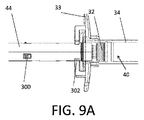
注射器市場をさらに複雑にしているのは、図5Aおよび図5Bに示すようなプレフィルド注射器アセンブリに対する需要の高まりであり、これは、通常、注射器本体、または「薬剤封じ込め送達システム」(34)、プランジャ先端部、プラグまたはストッパ(36)、およびルアータイプのインターフェース上に嵌合できる遠位シールまたはキャップ(35) を具える。(図5Aは、定位置のキャップ35を示しており;図5Bは、ルアーインターフェース14を示すためにキャップを取り外した状態を示す。)液体の薬剤は、プランジャ先端部(36)の遠位シールと遠位端(37)の間の体積内、または薬剤リザーバ内にある。プランジャ先端部(36)は標準的なブチルゴム材料でできており、生体適合性潤滑コーティング(例えばポリテトラフルオロエチレン(「PTFE」))などでコーティングして、関連する注射器本体構造及び材料に対して好ましいシーリングと、相対運動特性を容易にしている。 図5Bの注射器本体(34)の近位端は、注射器本体(34)の素材と一体的に形成された従来の一体型注射器フランジ(38)を具える。このフランジ(38)は、注射器本体(34)から半径方向に延在するように構成されており、注射器本体(34)の全周または一部の周囲となるように構成することができる。部分フランジは「クリップ付きフランジ」と呼ばれ、その他は「フルフランジ」と呼ばれる。フランジを使用して、注射器を指で握り、プランジャを押して注射をするための支持を提供する。注射器本体(34)は、好ましくは、ガラスまたはポリマーなどの半透明材料を具える。薬剤チャンバまたはリザーバ(40)内に収容容積を形成し、ニードルを通る関連流体の放出を助けるために、プランジャ先端部(36)を注射器本体(34)内に位置決めすることができる。注射器本体(34)は、実質的に円筒形状(すなわち、円形断面形状を有するプランジャ先端部36が注射器本体(34)に対してシールを確立できる)を画定するか、または楕円形などの他の断面形状を有するように構成してもよい。
Further complicating the syringe market is the growing demand for prefilled syringe assemblies as shown in FIGS. 5A and 5B, which is usually the syringe body, or the "drug containment delivery system" (34), plunger. It is equipped with a tip, a plug or stopper (36), and a distal seal or cap (35) that can be fitted onto a luer-type interface. (FIG. 5A shows the
このようなアセンブリは、充填、包装、および医薬品/薬剤の界面材料の選択とコンポーネント使用についての絶え間なく変化する世界の規制のすべてを満たす余裕があり、世界でも数少ない製造業者によって標準化され、量的に正確に製造することができるため、望ましい。しかしながら、このような単純な構成は、一般に、単回使用、安全性、自動無効化、およびニードル刺し防止に関する新しい世界標準を満たしていないであろう。したがって、特定のサプライヤは、図5Cに示されているような、より「垂直型」のソリューションに移行している。これは、1つのソリューションですべての基準、または少なくともその一部を満たす試みである。多くの異なるシナリオについてこれらの基準を満たすように試みた結果として、このような製品は大きな制限(図3乃至4Bを参照して上述したもののうちのいくつかを含む)があり、比較的多くの在庫と利用費用を有する。 Such assemblies can afford to meet all of the ever-changing global regulations on filling, packaging, and pharmaceutical / pharmaceutical interface material selection and component use, standardized and quantitative by one of the few manufacturers in the world. It is desirable because it can be manufactured accurately. However, such a simple configuration will generally not meet the new global standards for single use, safety, automatic disabling, and needle stick prevention. Therefore, certain suppliers are moving to more "vertical" solutions, as shown in Figure 5C. This is an attempt to meet all, or at least some of, all criteria in one solution. As a result of attempts to meet these criteria for many different scenarios, such products have significant limitations (including some of those mentioned above with reference to FIGS. 3-4B) and are relatively numerous. Has inventory and usage costs.
さらに、多くの注射可能な液体(例えば、薬)が、患者への送達の直前に2つ以上の成分を組み合わせて注射可能な組み合わせまたは溶液を作らなければならないというさらなる要件がある。注射可能な組み合わせを注射器に取り込む前に、複数の成分を別々の開放容器内で混合することができるが、開放容器内での混合および注射器内への引き込みは不正確であり、成分または注射可能な組み合わせの損失につながる。さらに、注射可能な組み合わせを注射器に引き込むことは、使用者をキャップのないニードルに不必要にさらすことにつながる。 In addition, there is an additional requirement that many injectable liquids (eg, drugs) must combine two or more components into an injectable combination or solution immediately prior to delivery to the patient. Multiple ingredients can be mixed in separate open containers before the injectable combination is taken into the syringe, but mixing in the open container and pulling into the syringe is inaccurate and the ingredients or injectable. It leads to the loss of various combinations. In addition, pulling the injectable combination into the syringe leads to unnecessary exposure of the user to the uncapped needle.
さらに、多くの注射可能な液体(例えば、薬剤)には、注射可能な液体が金属(例えば、ニードルのステンレス鋼)にさらされる時間を最小にするというさらに別の要件がある。 Furthermore, many injectable liquids (eg, drugs) have yet another requirement to minimize the amount of time the injectable liquid is exposed to the metal (eg, stainless steel of the needle).
現在利用可能な構成の欠点に対処する注射システムが必要とされている。特に、図5Aおよび図5Bを参照して説明したような、従来から供給されているプレフィルド注射器アセンブリの、既存の比較的よく制御されたサプライチェーンを利用することができる多室安全注射システムが必要とされている。 There is a need for an injection system that addresses the shortcomings of currently available configurations. In particular, there is a need for a multi-chamber safety injection system that can take advantage of the existing relatively well-controlled supply chain of traditionally supplied prefilled syringe assemblies, as described with reference to FIGS. 5A and 5B. It is said that.
注射システムに関する実施形態が記載されている。特に、この実施形態は、偶発的な使用者の怪我や使用済みのニードルによる汚染を最小限にするために、ニードルを保護構造内に移動させる多室型安全注射システムに関する。 Embodiments relating to the injection system are described. In particular, this embodiment relates to a multi-chamber safety injection system that moves the needle into a protective structure to minimize accidental user injury and contamination with used needles.
一実施形態では、医薬品を混合し注射するシステムが、近位開口部を画定している注射器本体と、その遠位端に遠位ニードルインターフェースとを具えている。このシステムはまた、注射器本体内に配置された近位および遠位ストッパ部材を具え、この近位および遠位ストッパ部材間に近位薬剤チャンバを、また、遠位ストッパ部材と注射器本体の遠位端との間に遠位薬剤チャンバを形成している。このシステムは、さらに、プランジャ内部を画定し、かつ手動で操作して注射器本体に近位ストッパ部材を挿入するように構成されたプランジャ部材を具える。このプランジャ部材は、プランジャ内部に配置されたニードル保持機構と、プランジャ内部に配置されたエネルギー貯蔵部材と、プランジャ内に配置されたエネルギー貯蔵部材ラッチ部材とを具える。このシステムは、さらに、注射器本体の遠位ニードルインターフェースに連結されたニードルハブアセンブリを具える。ニードルハブアセンブリは、ニードル近位端機構を有するニードル、ハブ、およびニードルをハブに連結するように構成されたニードルラッチ部材を具える。近位および遠位薬剤チャンバのそれぞれの第1および第2のサイズは、注射器本体に対する近位および遠位ストッパ部材の移動によって修正することができる。注射器本体に対してプランジャ部材を操作すると、ニードルは少なくとも部分的にプランジャ内部に引き込み可能になり、エネルギー貯蔵部材ラッチ部材をラッチ状態からラッチ解除状態に変える。 In one embodiment, a system for mixing and injecting medicinal products comprises a syringe body defining a proximal opening and a distal needle interface at its distal end. The system also comprises proximal and distal stopper members located within the syringe body, a proximal drug chamber between the proximal and distal stopper members, and a distal stopper member and a distal to the syringe body. It forms a distal drug chamber between the ends. The system further comprises a plunger member configured to demarcate the interior of the plunger and manually operate to insert the proximal stopper member into the syringe body. The plunger member includes a needle holding mechanism arranged inside the plunger, an energy storage member arranged inside the plunger, and an energy storage member latch member arranged inside the plunger. The system also comprises a needle hub assembly connected to the distal needle interface of the syringe body. The needle hub assembly comprises a needle having a needle proximal end mechanism, a hub, and a needle latch member configured to connect the needle to the hub. The first and second sizes of the proximal and distal drug chambers, respectively, can be modified by the movement of the proximal and distal stopper members with respect to the syringe body. Manipulating the plunger member with respect to the syringe body allows the needle to be at least partially retracted into the plunger, changing the energy storage member latch member from the latched state to the unlatched state.
別の実施形態では、医薬品を混合し注射するシステムが、近位開口部を画定するカートリッジ本体とその遠位端に遠位ニードルインターフェースとを具えている。このシステムはまた、カートリッジ本体内に配置された近位および遠位ストッパ部材を具え、近位および遠位ストッパ部材の間に近位薬剤チャンバを形成し、遠位ストッパ部材とカートリッジ本体の遠位端との間に遠位薬剤チャンバを形成している。このシステムは、さらに、プランジャ内部を画定し、手動で操作して近位ストッパ部材をカートリッジ本体に対して挿入するように構成されたプランジャ部材を具える。プランジャ部材は、プランジャ内部に配置されたニードル保持機構と、プランジャ内部に配置されたエネルギー貯蔵部材と、プランジャ内部に配置されたエネルギー貯蔵部材ラッチ部材とを具える。このシステムは、さらに、カートリッジ本体の遠位ニードルインターフェースに連結されたニードルハブアセンブリを具える。ニードルハブアセンブリは、ニードル近位端機構を有するニードル、ハブ、およびニードルをハブに連結するように構成されたニードルラッチ部材を具える。近位および遠位薬剤チャンバのそれぞれの第1および第2のサイズは、近位および遠位ストッパ部材のカートリッジ本体に対する移動によって修正することができる。ニードルは、カートリッジ本体に対してプランジャ部材を操作すると、プランジャ内部に少なくとも部分的に引き込み可能になり、エネルギー貯蔵部材ラッチ部材をラッチ状態からラッチ解除状態に変える。 In another embodiment, the system for mixing and injecting medicinal products comprises a cartridge body defining a proximal opening and a distal needle interface at its distal end. The system also comprises proximal and distal stopper members located within the cartridge body, forming a proximal drug chamber between the proximal and distal stopper members, the distal stopper member and the distal of the cartridge body. It forms a distal drug chamber between the ends. The system further comprises a plunger member configured to demarcate the interior of the plunger and manually operate to insert the proximal stopper member into the cartridge body. The plunger member includes a needle holding mechanism arranged inside the plunger, an energy storage member arranged inside the plunger, and an energy storage member latch member arranged inside the plunger. The system also comprises a needle hub assembly connected to the distal needle interface of the cartridge body. The needle hub assembly comprises a needle having a needle proximal end mechanism, a hub, and a needle latch member configured to connect the needle to the hub. The first and second sizes of the proximal and distal drug chambers, respectively, can be modified by moving the proximal and distal stopper members relative to the cartridge body. When the plunger member is operated with respect to the cartridge body, the needle can be pulled into the plunger at least partially, and changes the energy storage member latch member from the latched state to the unlatched state.
一又はそれ以上の実施形態では、ニードルは、少なくとも遠位ストッパ部材を完全に貫通してプランジャ内部に引き込まれるように構成されている。エネルギー貯蔵部材ラッチ部材は、プランジャ部材の内側面とニードル保持機構との間に相互連結することができる。近位および遠位薬剤チャンバはそれぞれ、患者に注射する前に一緒に混合するべき薬剤の第1および第2の成分を含んでいてもよい。 In one or more embodiments, the needle is configured to completely penetrate at least the distal stopper member and be drawn into the plunger. The energy storage member latch member can be interconnected between the inner surface of the plunger member and the needle holding mechanism. Proximal and distal drug chambers may contain first and second components of the drug to be mixed together prior to injection into the patient, respectively.
一又はそれ以上の実施形態では、このシステムが、ニードルの近位端部機構が遠位薬剤チャンバ内に配置されている輸送構成と、ニードルの近位端部機構が遠位部分ストッパ部材を少なくとも部分的に貫通して、近位薬剤チャンバ内に少なくとも部分的に配置されている移送構成と、近位および遠位ストッパ部材が互いに接触しており、それによって第1の薬剤成分を近位薬剤チャンバから遠位薬剤チャンバに移して第1の薬剤成分を遠位薬剤チャンバ内の第2の薬剤構成要素と混合する混合構成と、を具える。ニードルは、遠位端開口部と、システムが輸送、移送、および混合構成にあるときに遠位薬剤チャンバ内に配置される中間開口部と、システムが輸送、及び移送構成にあるときに近位薬剤チャンバ内に配置される近位開口部と、を具える。 In one or more embodiments, the system comprises a transport configuration in which the proximal end mechanism of the needle is located within the distal drug chamber and the proximal end mechanism of the needle at least the distal partial stopper member. The transfer configuration, which is partially penetrating and at least partially located within the proximal drug chamber, and the proximal and distal stopper members are in contact with each other, thereby causing the first drug component to be proximal drug. It comprises a mixed configuration, which is transferred from the chamber to the distal drug chamber and the first drug component is mixed with the second drug component in the distal drug chamber. The needle is proximal to the distal end opening and the intermediate opening that is placed within the distal drug chamber when the system is in the transport, transfer, and mixed configuration, and when the system is in the transport, transfer, and transfer configuration. It comprises a proximal opening, which is located within the drug chamber.
一またはそれ以上の実施形態において、ニードルは、複数の近位開口部を具え、この近位開口部が複数の近位開口部のうちの一つである。システムが輸送構成および移送構成にあるときに、少なくともいくつかの近位開口部が近位薬剤チャンバ内に配置され、システムが混合構成にあるときは少なくともいくつかの近位開口部が近位ストッパ部材によって閉塞される。 近位ストッパ部材は、システムが混合構成にあるときに少なくともいくつかの近位開口部を閉塞するように構成されたプラグを具える。このプラグの長さは、複数の近位開口部のうち最も近位側の開口部と、複数の近位開口部のうちの最も遠位側の開口部との間の距離よりも大きい。 In one or more embodiments, the needle comprises a plurality of proximal openings, the proximal opening being one of the plurality of proximal openings. At least some proximal openings are placed in the proximal drug chamber when the system is in transport and transport configurations, and at least some proximal openings are proximal stoppers when the system is in mixed configurations. It is blocked by a member. The proximal stopper member comprises a plug configured to close at least some proximal openings when the system is in a mixed configuration. The length of this plug is greater than the distance between the most proximal opening of the plurality of proximal openings and the most distal opening of the plurality of proximal openings.
一またはそれ以上の実施形態では、注射器またはカートリッジ本体が、システムが混合構成にあるときに遠位ストッパの遠位端に隣接するように構成された位置表示器を具えている。プランジャ部材は、システムが混合構成にあるときに注射器またはカートリッジ本体に選択的に結合され、注射器またはカートリッジ本体に対するプランジャ部材の近位方向の移動を防止するように構成された保持クリップを具えていてもよい。この保持クリップは、保持クリップが注射器またはカートリッジ本体に選択的に連結されたときに、可聴信号を生成するように構成してもよい。 In one or more embodiments, the syringe or cartridge body comprises a position indicator configured to be adjacent to the distal end of the distal stopper when the system is in a mixed configuration. The plunger member comprises a retaining clip configured to be selectively coupled to the syringe or cartridge body when the system is in a mixed configuration and to prevent proximal movement of the plunger member with respect to the syringe or cartridge body. May be good. The retaining clip may be configured to generate an audible signal when the retaining clip is selectively coupled to the syringe or cartridge body.
一またはそれ以上の実施形態では、近位および遠位ストッパは、それぞれ遠位および近位表面上にそれぞれ第1および第2のポリマーコーティングを具えており、近位薬剤チャンバが注射器またはカートリッジ本体と、第1および第2のポリマーコーティングによって画定される。遠位ストッパは、近位方向にテーパがついている漏斗と、この漏斗のテーパ近位端に配置された空間とを有していてもよい。 In one or more embodiments, the proximal and distal stoppers are provided with first and second polymer coatings on the distal and proximal surfaces, respectively, with the proximal drug chamber with the syringe or cartridge body. , 1st and 2nd polymer coatings. The distal stopper may have a funnel tapered in the proximal direction and a space located at the proximal end of the taper of the funnel.
一又はそれ以上の実施形態では、ハブがコレットとスリーブを具えている。コレットは、スリーブがコレットの周りに配置されると、ニードルハブアセンブリをカートリッジ本体の遠位ニードルインターフェースに取り外し可能に連結するように構成することができる。ハブは、ニードルの外側面を囲み、その周囲に液密シールを形成するように構成されたシール部材を具えていてもよい。 In one or more embodiments, the hub comprises a collet and a sleeve. The collet can be configured to detachably connect the needle hub assembly to the distal needle interface of the cartridge body once the sleeve is placed around the collet. The hub may include a sealing member configured to surround the outer surface of the needle and form a liquidtight seal around it.
一又はそれ以上の実施形態において、このシステムはさらに、遠位薬剤チャンバ内に配置された移送パイプを具える。ニードルハブアセンブリがカートリッジ本体の遠位ニードルインターフェースに取り外し可能に連結されると、ニードルと移送パイプとは取り外し可能に連結される。移送パイプは、その遠位端に小径部分を有しており、それにニードルを固定するように構成できる。 In one or more embodiments, the system further comprises a transfer pipe located within the distal drug chamber. Once the needle hub assembly is detachably connected to the distal needle interface of the cartridge body, the needle and transfer pipe are detachably connected. The transfer pipe has a small diameter portion at its distal end and can be configured to secure the needle to it.
さらに別の実施形態では、注射用システムが、近位開口部を画定する注射器本体と、その遠位端に遠位ニードルインターフェースとを具えている。このシステムはまた、注射器本体内に配置された近位および遠位ストッパ部材を具え、この近位および遠位ストッパ部材の間に薬剤チャンバを形成している。このシステムはさらに、プランジャ内部を画定し、手動で操作して近位ストッパ部材を注射器本体に対して挿入するように構成されたプランジャ部材を具える。このプランジャ部材は、プランジャ内部に配置されたニードル保持機構と、プランジャ内部に配置されたエネルギー貯蔵部材と、プランジャ内部に配置されたエネルギー貯蔵部材ラッチ部材とを具える。このシステムはさらに、注射器本体の遠位ニードルインターフェースに連結されたニードルハブアセンブリを具える。このニードルハブアセンブリは、ニードル近位端機構を有するニードルと、ハブと、ニードルをハブに連結するように構成されたニードルラッチ部材とを具える。ニードル近位端機構は、システムが注射構成にあるときに遠位ストッパ部材が薬剤チャンバ内を貫通するように構成されている。注射器本体に対してプランジャ部材を操作するとき、ニードルは少なくとも部分的にプランジャ内部に引き込み可能であり、エネルギー貯蔵部材ラッチ部材をラッチ状態からラッチ解除状態に変える。 In yet another embodiment, the injection system comprises a syringe body defining a proximal opening and a distal needle interface at its distal end. The system also comprises proximal and distal stopper members located within the syringe body, forming a drug chamber between the proximal and distal stopper members. The system further comprises a plunger member configured to demarcate the interior of the plunger and manually operate to insert the proximal stopper member into the syringe body. The plunger member includes a needle holding mechanism arranged inside the plunger, an energy storage member arranged inside the plunger, and an energy storage member latch member arranged inside the plunger. The system also comprises a needle hub assembly connected to the distal needle interface of the syringe body. The needle hub assembly comprises a needle having a needle proximal end mechanism, a hub, and a needle latch member configured to connect the needle to the hub. The needle proximal end mechanism is configured so that the distal stopper member penetrates the drug chamber when the system is in the injection configuration. When manipulating the plunger member with respect to the syringe body, the needle is at least partially retractable into the plunger, changing the energy storage member latch member from the latched state to the unlatched state.
一又はそれ以上の実施形態において、薬剤チャンバは、ニードルの金属材料との接触による保管中の劣化に敏感な薬剤を含んでいる。近位および遠位ストッパは、それぞれの遠位面および近位面上にそれぞれ第1および第2のポリマーコーティングを具えており、薬剤チャンバが注射器本体ならびに第1および第2のポリマーコーティングによって画定されている。 In one or more embodiments, the drug chamber comprises a drug that is sensitive to deterioration during storage due to contact of the needle with the metallic material. Proximal and distal stoppers have first and second polymer coatings on their respective distal and proximal surfaces, respectively, and the drug chamber is defined by the syringe body and the first and second polymer coatings. ing.
一又はそれ以上の実施形態では、システムは、ニードル近位端機構が薬剤チャンバの内側に配置されていない輸送構成を具えている。ニードル近位端機構は、遠位ストッパを貫通していてもよく、薬剤チャンバ内に配置され、それによってシステムが注射構成にあるときに薬剤を患者に注射する薬剤出口経路を提供している。 In one or more embodiments, the system comprises a transport configuration in which the needle proximal end mechanism is not located inside the drug chamber. The needle proximal end mechanism may penetrate the distal stopper and is located within the drug chamber, thereby providing a drug exit route for injecting the drug into the patient when the system is in the injection configuration.
一又はそれ以上の実施形態では、ニードルが、遠位端開口部と、システムが輸送および注射構成にあるときに薬剤チャンバ内に配置される中間開口部と、システムが注射構成にあるときに薬剤チャンバ内に配置される近位開口部と、を具える。 In one or more embodiments, the needle is placed in the distal end opening and in the drug chamber when the system is in the transport and injection configuration, and the drug when the system is in the injection configuration. It comprises a proximal opening, which is located within the chamber.
さらに別の実施形態では、薬を混合して患者に注射する方法が、近位開口部を画定する注射器本体と、その遠位端に遠位ニードルインターフェースとを具えるシステムを提供するステップを具える。このシステムはまた、注射器本体に配置された近位および遠位ストッパ部材を具え、近位および遠位ストッパ部材の間に近位薬剤チャンバを形成し、遠位ストッパ部材と注射器本体の遠位端との間に遠位薬剤チャンバを形成している。このシステムはさらに、プランジャ内部を画定し、かつ手動で操作して近位ストッパ部材を注射器本体に対して挿入するように構成されたプランジャ部材を具える。さらに、このシステムは、遠位ニードル先端と、薬剤通路と、複数の移送開口部と、近位端とを具えるニードル部材を具える。この方法はまた、プランジャ部材を前進させてニードル部材の近位端を遠位ストッパに突き刺して、近位薬剤チャンバから第1の薬剤成分を薬剤通路を通って遠位薬剤チャンバ内に送り、遠位薬剤チャンバ内で第1の薬剤成分と第2の薬剤成分とを混合して混合薬剤を形成する、ステップを具える。 In yet another embodiment, the method of mixing and injecting a drug comprises the step of providing a system comprising a syringe body defining a proximal opening and a distal needle interface at its distal end. Eh. The system also comprises proximal and distal stopper members located on the syringe body, forming a proximal drug chamber between the proximal and distal stopper members, the distal stopper member and the distal end of the syringe body. It forms a distal drug chamber between and. The system further comprises a plunger member configured to demarcate the interior of the plunger and manually operate to insert the proximal stopper member into the syringe body. In addition, the system comprises a needle member comprising a distal needle tip, a drug passage, multiple transfer openings, and a proximal end. This method also advances the plunger member to pierce the proximal end of the needle member into the distal stopper, sending the first drug component from the proximal drug chamber through the drug passage into the distal drug chamber and far away. It comprises a step of mixing the first drug component and the second drug component in the drug chamber to form a mixed drug.
別の実施形態では、薬剤を混合し患者に注射する方法が、近位開口部を画定するカートリッジ本体と、その遠位端にある遠位ニードルインターフェースとを具えるシステムを提供するステップを具える。このシステムはまた、カートリッジ本体内に配置された近位および遠位ストッパ部材を具えており、近位および遠位ストッパ部材の間に近位薬剤チャンバを形成し、遠位ストッパ部材とカートリッジ本体の遠位端との間に遠位薬剤チャンバを形成している。このシステムはさらに、プランジャ内部を画定し、手動で操作してカートリッジ本体に対して近位ストッパ部材を挿入するように構成されたプランジャ部材を具える。さらに、このシステムは、遠位ニードル先端と、薬剤通路と、複数の移送開口部と、近位端とを具えるニードル部材を具える。この方法はまた、プランジャ部材を前進させてニードル部材の近位端を遠位ストッパに突き刺して、近位薬剤チャンバから薬剤通路を通って第1の薬剤成分を通過させ、遠位薬剤チャンバ内で第1の薬剤成分と第2の薬剤成分とを混合して混合薬剤を形成する、ステップを具える。 In another embodiment, a method of mixing and injecting a drug comprises a step of providing a system comprising a cartridge body defining a proximal opening and a distal needle interface at its distal end. .. The system also comprises proximal and distal stopper members located within the cartridge body, forming a proximal drug chamber between the proximal and distal stopper members, the distal stopper member and the cartridge body. It forms a distal drug chamber between it and the distal end. The system further comprises a plunger member configured to demarcate the interior of the plunger and manually operate to insert a proximal stopper member into the cartridge body. In addition, the system comprises a needle member comprising a distal needle tip, a drug passage, multiple transfer openings, and a proximal end. This method also advances the plunger member to pierce the proximal end of the needle member into the distal stopper, allowing the first drug component to pass from the proximal drug chamber through the drug passage and within the distal drug chamber. It comprises a step of mixing the first drug component and the second drug component to form a mixed drug.
一又はそれ以上の実施形態では、この方法はさらに、プランジャ部材を前進させて混合薬剤を患者に注射するステップを具える。この方法は、混合薬が患者に注射されると、遠位ニードル先を注射器本体内に自動的に引き込むステップを具えていてもよい。 In one or more embodiments, the method further comprises a step of advancing the plunger member to inject the mixed drug into the patient. The method may comprise a step of automatically pulling the distal needle tip into the syringe body when the mixture is injected into the patient.
さらに別の実施形態では、患者に薬を注射する方法が、近位開口部を画定する注射器本体と、その遠位端に遠位ニードルインターフェースとを具えるシステムを提供するステップを具える。このシステムはまた、注射器本体内に配置された近位および遠位ストッパ部材を具え、近位ストッパ部材と遠位ストッパ部材との間に薬剤チャンバを形成し、遠位ストッパ部材と注射器本体の遠位端との間に遠位薬剤チャンバを形成している。このシステムはさらに、プランジャ内部を画定し、手動で操作して近位ストッパ部材を注射器本体に対して挿入するようにしたプランジャ部材を具える。さらに、このシステムは、遠位ニードル先端と、薬剤通路と、複数の移送開口部と、近位端とを有するニードル部材を具える。この方法はまた、プランジャ部材を前進させてニードル部材の近位端を遠位ストッパに突き刺して、近位薬剤チャンバから薬剤通路を通って遠位薬剤チャンバ内へ薬剤を通過させるステップを具える。 In yet another embodiment, the method of injecting a drug into a patient comprises a step of providing a system comprising a syringe body defining a proximal opening and a distal needle interface at its distal end. The system also comprises proximal and distal stopper members located within the syringe body, forming a drug chamber between the proximal stopper member and the distal stopper member, and the distal stopper member and the syringe body far away. It forms a distal drug chamber between the ends. The system also comprises a plunger member that defines the interior of the plunger and is manually manipulated to insert the proximal stopper member into the syringe body. In addition, the system comprises a needle member having a distal needle tip, a drug passage, multiple transfer openings, and a proximal end. The method also comprises a step of advancing the plunger member to pierce the proximal end of the needle member into the distal stopper to allow the drug to pass from the proximal drug chamber through the drug passage into the distal drug chamber.
一又はそれ以上の実施形態では、この方法はまた、プランジャ部材を前進させて薬を患者に注射するステップを具える。この方法は、混合薬が患者に注射されると、遠位ニードル先を注射器本体内に自動的に引き込むステップをさらに具えている。 In one or more embodiments, the method also comprises a step of advancing the plunger member to inject the drug into the patient. This method further comprises the step of automatically pulling the distal needle tip into the syringe body when the mixture is injected into the patient.
さらに別の実施形態では、医薬品を混合し注射するシステムが、近位開口部を画定する注射器本体と、その遠位端に遠位ニードルインターフェースとを具える。このシステムはまた、注射器本体内に配置された近位および遠位ストッパ部材を具えており、近位および遠位ストッパ部材と遠位ストッパ部材と注射器本体の遠位端との間に近位薬剤チャンバを形成している。このシステムはさらに、プランジャ内部を画定し、かつ手動で操作して近位ストッパ部材を注射器本体に対して挿入するように構成されたプランジャ部材を具える。プランジャ部材は、プランジャ内部に配置されたニードル保持機構と、プランジャ内部に配置されたエネルギー貯蔵部材と、プランジャ内部に配置されたエネルギー貯蔵部材ラッチ部材とを具える。さらに、このシステムは、注射器本体の遠位ニードルインターフェースに連結されたニードルハブアセンブリを具える。このニードルアセンブリは、ニードル近位端機構を有するニードル、ハブ、およびニードルをハブに連結するように構成されたニードルラッチ部材を具える。近位および遠位薬剤チャンバのそれぞれの第1および第2のサイズは、近位および遠位ストッパ部材の注射器本体に対する移動によって修正することができる。注射器本体に対してプランジャ部材を操作すると、ニードルは少なくとも部分的にプランジャ内部に引き込み可能となり、エネルギー貯蔵部材ラッチ部材をラッチ状態からラッチ解除状態に変える。遠位薬剤チャンバは部分真空を具える。 In yet another embodiment, the system for mixing and injecting medicinal products comprises a syringe body defining a proximal opening and a distal needle interface at its distal end. The system also comprises proximal and distal stopper members located within the syringe body, between the proximal and distal stopper members and the distal stopper member and the distal end of the syringe body. Forming a chamber. The system further comprises a plunger member configured to demarcate the interior of the plunger and manually operate to insert the proximal stopper member into the syringe body. The plunger member includes a needle holding mechanism arranged inside the plunger, an energy storage member arranged inside the plunger, and an energy storage member latch member arranged inside the plunger. In addition, the system comprises a needle hub assembly connected to the distal needle interface of the syringe body. The needle assembly comprises a needle having a needle proximal end mechanism, a hub, and a needle latch member configured to connect the needle to the hub. The first and second sizes of the proximal and distal drug chambers, respectively, can be modified by the movement of the proximal and distal stopper members relative to the syringe body. Manipulating the plunger member with respect to the syringe body allows the needle to be at least partially retracted into the plunger, changing the energy storage member latch member from the latched state to the unlatched state. The distal drug chamber is equipped with a partial vacuum.
一又はそれ以上の実施形態では、遠位ストッパ部材が近位ゲートを具えており、ニードル近位端機構が近位ゲートを通過できない閉構成と、近位ゲートを通過できる開構成とを具える。近位ゲートは、ばね要素対に動作可能に連結された可動アーム対を具えている。このばね要素対は、閉構成で近位ゲートを付勢する。ニードル近位端構造は、閉構成では近位ゲートを通過することはできないが、開構成では近位ゲートを通過することができる近位ショルダを具えていてもよい。ニードルは、閉構成では近位ゲートを通過することはできないが、開構成では近位ゲートを通過することができる遠位ショルダを具えており、この遠位ショルダは近位ショルダの遠位にある。近位ゲートは、自己付勢ヒンジ対に動作可能に連結された可動アーム対を具えていてもよい。 In one or more embodiments, the distal stopper member comprises a proximal gate and the needle proximal end mechanism comprises a closed configuration that does not allow passage through the proximal gate and an open configuration that allows passage through the proximal gate. .. The proximal gate comprises a pair of movable arms operably connected to a pair of spring elements. This pair of spring elements urges the proximal gate in a closed configuration. The needle proximal end structure may include a proximal shoulder that cannot pass through the proximal gate in the closed configuration but can pass through the proximal gate in the open configuration. The needle is equipped with a distal shoulder that cannot pass through the proximal gate in the closed configuration but can pass through the proximal gate in the open configuration, which is distal to the proximal shoulder. .. The proximal gate may be equipped with a pair of movable arms operably connected to a pair of self-arming hinges.
別の実施形態では、薬剤を混合し患者に注射する方法が、近位開口部を画定する注射器本体と、その遠位端に遠位ニードルインターフェースとを具えるシステムを提供するステップを具える。このシステムはまた、注射器本体に配置された近位および遠位ストッパ部材を具え、近位および遠位ストッパ部材の間に近位薬剤チャンバを形成し、遠位ストッパ部材と注射器本体の遠位端との間に遠位薬剤チャンバを形成している。このシステムは、プランジャ内部を画定し、かつ手動で操作して近位ストッパ部材を注射器本体に対して挿入するように構成されたプランジャ部材をさらに具える。さらに、このシステムは、遠位ニードル先端と、薬剤通路と、複数の移送開口部と、近位端とを有するニードル部材を具える。遠位薬剤チャンバは部分真空を含む。この方法はまた、プランジャ部材を前進させて遠位ストッパ部材を通ってニードル部材の近位に突き刺して、遠位薬剤チャンバ内の部分真空が近位薬剤チャンバから薬剤通路を通って第1の薬剤成分を遠位薬剤チャンバ内に吸引し、遠位薬剤チャンバ内で第1の薬剤成分と第2の薬剤成分とを混合して混合薬剤を形成できるようにするステップを具える。 In another embodiment, the method of mixing and injecting a drug comprises a step of providing a system comprising a syringe body defining a proximal opening and a distal needle interface at its distal end. The system also comprises proximal and distal stopper members located on the syringe body, forming a proximal drug chamber between the proximal and distal stopper members, the distal stopper member and the distal end of the syringe body. It forms a distal drug chamber between and. The system further comprises a plunger member configured to demarcate the interior of the plunger and manually operate to insert the proximal stopper member into the syringe body. In addition, the system comprises a needle member having a distal needle tip, a drug passage, multiple transfer openings, and a proximal end. The distal drug chamber contains a partial vacuum. This method also advances the plunger member through the distal stopper member and pierces proximally to the needle member, allowing partial vacuum within the distal drug chamber to pass from the proximal drug chamber through the drug passage to the first drug. A step is provided in which the components are aspirated into the distal drug chamber and the first drug component and the second drug component are mixed in the distal drug chamber to allow the formation of a mixed drug.
一又はそれ以上の実施形態では、この方法はまた、遠位ストッパ部材を遠位方向に移動させて遠位薬剤チャンバ内の空間を潰し、システムをパージすることなくシステムで注射を行えるようにするステップを具える。この方法はまた、プランジャ部材を前進させて薬剤を患者に注射するステップを具えていてもよい。この方法は、薬剤が患者に注射されると、遠位ニードル先端を注射器本体内に自動的に引き込むステップをさらに具えていてもよい。 In one or more embodiments, the method also moves the distal stopper member distally to crush the space within the distal drug chamber, allowing the system to inject without purging the system. Equipped with steps. The method may also comprise the step of advancing the plunger member to inject the drug into the patient. The method may further comprise a step of automatically pulling the distal needle tip into the syringe body when the agent is injected into the patient.
本発明の前述した実施形態およびその他の実施形態は、以下の詳細な説明に記載されている。 The aforementioned embodiments and other embodiments of the present invention are described in detail below.
実施形態の前述した態様および他の態様を、添付の図面を参照してさらに詳細に説明する。図面中の同じ要素は共通の参照番号を付して説明する。
様々な実施形態の上記および他の利点および目的をいかにして達成するかをよりよく理解するために、添付の図面を参照しながら実施形態をより詳細に説明する。図面は一定の縮尺で描かれておらず、類似の構造または機能の要素は全体を通して同じ参照番号で表されていることに留意されたい。これらの図面は特定の例示的な実施形態を説明するだけのものであり、実施形態の範囲を限定すると見なされるべきではないことは自明である。 The embodiments will be described in more detail with reference to the accompanying drawings in order to better understand how to achieve the above and other advantages and objectives of the various embodiments. Note that the drawings are not drawn to a constant scale and elements of similar structure or function are represented by the same reference number throughout. It is self-evident that these drawings merely illustrate certain exemplary embodiments and should not be considered to limit the scope of the embodiments.
例示的な二室式安全注射器システム
図6A及び6Bを参照すると、内部に従来の近位および遠位ストッパ(32、36)を設けた従来の市販のプレフィルド注射器本体(34)を具える二室式安全注射システムの斜視図および縦断面図が示されている。近位および遠位ストッパ部材(32、36)は、注射器本体(34)と共に、近位および遠位の薬剤チャンバ(40、42)を画定している。近位および遠位ストッパ部材(36、37)は、近位薬剤チャンバ(40)の近位端および遠位端を閉塞している。遠位ストッパ部材(36)は、遠位薬剤チャンバ(42)の近位端を閉塞している。ニードル連結アセンブリ(606)は、保管用に設置されたニードルカバー部材(63)と共に遠位薬剤チャンバ(42)の遠位端に配置されている。二室式安全注射システムは、近位薬剤チャンバ(40)から遠位薬剤チャンバ(42)への第1の薬剤成分の移送と、ユーザによる様々な程度の注射器本体(34)に対するプランジャアセンブリの連続挿入を受けた遠位薬剤チャンバ(42)からの混合/組み合わせ薬剤の排出と、を制御する。プランジャアセンブリは、近位ストッパ部材(32)、プランジャハウジング部材(69)、およびプランジャ操作インターフェース(128)を具える。近位薬剤チャンバ(40)内に配置されている第1の薬剤成分は、水性またはオイルベースの薬剤溶液、ゲルといった液体であるか、あるいは、第1の薬剤成分は、遠位薬剤チャンバ(42)内で第2の薬剤成分と混合する希釈剤であってもよい。遠位薬剤チャンバ(42)内の第2の薬剤成分は、粉末、ミクロスフェア、乳剤、凍結乾燥薬剤またはフリーズドライ薬剤といった乾燥形態の薬剤であっても、または固形薬剤のようなケーキ状薬剤であってもよい。遠位薬剤チャンバ(42)内の第2の薬剤成分は、近位薬剤チャンバ(40)からの第1の薬剤成分と混合する液体であってもよい。
Exemplary Two-chamber Safety Syringe System With reference to FIGS. 6A and 6B, a two-chamber equipped with a conventional commercially available prefilled syringe body (34) with conventional proximal and distal stoppers (32, 36) inside. A perspective view and a vertical cross-sectional view of the formula safety injection system are shown. Proximal and distal stopper members (32, 36), along with the syringe body (34), define the proximal and distal drug chambers (40, 42). Proximal and distal stopper members (36, 37) occlude the proximal and distal ends of the proximal drug chamber (40). The distal stopper member (36) occludes the proximal end of the distal drug chamber (42). The needle connection assembly (606) is located at the distal end of the distal drug chamber (42) along with a needle cover member (63) installed for storage. The two-chamber safety injection system is a continuous transfer of the first drug component from the proximal drug chamber (40) to the distal drug chamber (42) and the plunger assembly to the syringe body (34) to varying degrees by the user. Controls withdrawal of the mixed / combined drug from the distal drug chamber (42) that received the insertion. The plunger assembly comprises a proximal stopper member (32), a plunger housing member (69), and a plunger operating interface (128). The first drug component located within the proximal drug chamber (40) is a liquid such as an aqueous or oil-based drug solution, gel, or the first drug component is the distal drug chamber (42). ) May be a diluent to be mixed with the second drug component. The second drug component in the distal drug chamber (42) may be a dry form drug such as a powder, microsphere, emulsion, lyophilized drug or freeze-dried drug, or a cake-like drug such as a solid drug. There may be. The second drug component in the distal drug chamber (42) may be a liquid that mixes with the first drug component from the proximal drug chamber (40).
二室式安全注射システムは、ステーキドニードル構成を有し、ユーザに提示すると、ニードル連結アセンブリ(606)、ニードルの遠位端/先端部(48)、ニードル連結部材(83、例えば、図6E参照)、およびニードルの近位端(50)を具えるニードルアセンブリが、ニードルカバー部材(63)の除去後に注射の準備が整った位置に装着される。カバー部材は、内面にエラストマーシール材料を具えており、保管中にニードルの遠位端(48)または遠位ハウジング部分(610)と接合している。代替的に、ニードルカバー部材(63)は、汚染が注射器本体(34)に入るのを防ぎつつ、薬剤成分の移動および混合から生じる圧力を注射器本体(34)の内側から逃がすための通気口(図示せず)を具えていてもよい。ステーキドニードルは定位置に装着されているように描かれているが、ステーキドニードルはルアーインターフェースを用いて注射器本体(34)に、ルアーインターフェースを通って遠位薬剤チャンバ(42)内に延在するニードル部材の近位端(50)とともに、取り外し可能に連結するようにしてもよい。図6A乃至図22Dに示す実施形態では、安全なニードル後退ハードウェアの大部分がプランジャハウジング内にある。 The two-chamber safety injection system has a steaked needle configuration and is presented to the user with a needle connecting assembly (606), a distal end / tip (48) of the needle, a needle connecting member (83, eg, FIG. 6E). The needle assembly, which comprises the proximal end (50) of the needle, is mounted in a position ready for injection after removal of the needle cover member (63). The cover member comprises an elastomeric sealing material on the inner surface, which is joined to the distal end (48) or distal housing portion (610) of the needle during storage. Alternatively, the needle cover member (63) is a vent (34) for releasing the pressure resulting from the movement and mixing of the drug components from the inside of the syringe body (34) while preventing contamination from entering the syringe body (34). (Not shown) may be provided. The steaked needle is depicted as being mounted in place, but the steaked needle extends into the syringe body (34) using the luer interface and into the distal drug chamber (42) through the luer interface. It may be detachably connected together with the proximal end (50) of the existing needle member. In the embodiments shown in FIGS. 6A-22D, most of the safe needle retracting hardware is in the plunger housing.
図6Cおよび図6Dを参照すると、最初の組み立て時(すなわち、工場または処理施設内 −「ステーキドニードル」構成の現場ではない)に、近位ハウジングアッセンブリ(608)が、注射器本体の製造時に注射器本体内に形成される注射器本体のわずかに凹んだ半径方向部分(602)上にスナップ嵌合するように構成されている(すなわち、近位ハウジングアセンブリを具えるか、またはそれに連結されたスナップリング要素604を使用して)。 Referring to FIGS. 6C and 6D, during initial assembly (ie, in a factory or processing facility-not in the field of a "steaked needle" configuration), the proximal housing assembly (608) is a syringe during the manufacture of the syringe body. A snap ring configured to snap fit onto a slightly recessed radial portion (602) of the syringe body formed within the body (ie, with or attached to a proximal housing assembly). Using element 604).
図6Eおよび図6Fを参照すると、ニードルスパインアセンブリ(76)は、遠位ニードル端部(48)と、ニードル接続部材(83)に連結されたニードル近位端部(50)とを有する注射部材を具える。ニードル連結部材(83)は、ラッチ部材(612)と可動ブロック部材(614)と接合するように構成された狭窄または径方向縮小部分(111)を有するように構成されており、注射中に、ニードル遠位端部(48)、ニードル連結部材(83)、およびニードル近位端部(50)が、注射器本体(34)に対して定位置に固定されたままであるが、プランジャアセンブリを小径フランジ(80)に対して完全に挿入した後(33−例えば、図7N参照)(すなわち、注射器本体34の遠位薬剤チャンバ42内に収容される薬剤の完全放出の前後)に、可動ブロック部材(614)が遠位ハウジング部分(610)に対して前進して、複数の片持ちラッチ部材(616)(2つが図示されている)が可動ハウジングによって邪魔にならないところに押圧される。特に、ニードルスパインアセンブリ(76)は、プランジャアセンブリの完全な前進によって遠位方向に力を受け、可動ブロック部材(614)を前進させて片持ちラッチ部材(616)を移動させる。片持ち式ラッチ部材(616)を動かすことによって、ニードルの遠位端(48)、接続部材(83)、および近位端(50)をそれらの連結部を通して後退させることができ、それによってニードルの遠位端(48)がプランジャハウジング部材(69)内に安全に配置される。代替的に、ニードルの遠位端(48)を、遠位ハウジング部分(610)の外面の下の位置に引っ込めて、鋭利な先端をユーザから安全に保護することができる。換言すると、片持ち式ラッチ部材(616)は、プランジャを完全に挿入した時に可動ブロック部材(614)によって邪魔にならないところに押し出されるまで、注射を行う間、ニードル/注射器アセンブリとニードルの遠位端(48)の位置を保持する。プランジャを完全に挿入した後は、米国特許出願第09 / 099,952号、第14/696,342および第62/416,102号に記載されているように、ニードルスパインアセンブリ(76)のさらなる遠位方向への移動によってトリガされたときに、ニードルが自動的に引き抜くべく自由になる。これらの米国特許出願は、引用により本明細書に組み込まれている。
Referring to FIGS. 6E and 6F, the needle spine assembly (76) is an injection member having a distal needle end (48) and a needle proximal end (50) connected to a needle connecting member (83). To have. The needle connecting member (83) is configured to have a constriction or radial shrinkage portion (111) configured to join the latch member (612) and the movable block member (614) during injection. The needle distal end (48), needle connecting member (83), and needle proximal end (50) remain fixed in place with respect to the syringe body (34), but the plunger assembly is fitted with a small diameter flange. After full insertion into (80) (33-see, eg, FIG. 7N) (ie, before and after complete release of the drug contained within the
一実施形態では、プランジャアセンブリはプランジャアセンブリ内にギャップを形成する連結部材を具えており、遠位ストッパ部材が注射器本体の遠位端に到達して注射器本体から混合薬剤をほぼすべて排出した後に、プランジャ操作インターフェースを遠位方向に移動し続けることができる。この実施形態では、完全注射後にプランジャ操作インターフェースを遠位方向に少しだけ押して、連結部材およびギャップを崩し、片持ち式ラッチ部材を解放し、ニードルスパインアセンブリをエネルギー貯蔵部材に連結し、エネルギー貯蔵部材を解放して、連結したニードルスパインアセンブリを少なくとも注射器本体内に引き込む。この実施形態は、参照により本明細書に組み込まれている米国特許出願第62/416、102号さらに詳細に記載されている。 In one embodiment, the plunger assembly comprises a connecting member that forms a gap within the plunger assembly after the distal stopper member reaches the distal end of the syringe body and expels almost all of the mixed drug from the syringe body. The plunger operating interface can continue to move distally. In this embodiment, after a complete injection, the plunger operating interface is pushed slightly distally to break the coupling member and gap, release the cantilever latch member, connect the needle spine assembly to the energy storage member, and the energy storage member. Release and pull the connected needle spine assembly at least into the syringe body. This embodiment is described in more detail in US Patent Application Nos. 62/416, 102, which is incorporated herein by reference.
図6Eは、ニードル連結アセンブリ(606)のないニードルアセンブリの要素を具えるニードルスパインアセンブリ(76)の態様を示す。ニードルスパインアセンブリ(76)の遠位部(48)は、注射部材(78)上に形成された鋭利な皮下注射ニードル先端を具える。図6Gおよび6Hに示すように、ニードルの近位端(50)は、遠位部分を形成する連結部材に形成された鋭利な先端部(86)も具えている。ほぼ中空の結合部材(83)が、連結部材を筒状注射部材(78)に連結する。注射部材(78)、ニードルの近位端(50)上の鋭利な先端部(86)、および中空結合部材(83)は、締まり嵌め、溶接、および/または接着剤で共に保持されている。図に示す実施形態におけるニードル近位端(50)の最も近位側端部(84)は、以下にさらに詳細に説明するように、「ハープーン」型の幾何学形状を具えており、これは、ニードルスパインアセンブリ(76)をプランジャハウジング部材(69)内に引き込むために、接合する従属部材に突き刺さって保持されるように構成されている。ニードルの近位端(50)は、例えば、レーザカッティング、エッチング、打ち抜き加工、および/または機械加工技術を用いて薄板金属部品から作ることができる。ニードルスパインアセンブリ(76)の他の態様、例えばそれを通る流路および流れの閉塞は、少なくとも図6M乃至6Oに示されており、以下に説明する。 FIG. 6E shows an embodiment of a needle spine assembly (76) comprising elements of a needle assembly without a needle connecting assembly (606). The distal portion (48) of the needle spine assembly (76) comprises a sharp subcutaneous injection needle tip formed on the injection member (78). As shown in FIGS. 6G and 6H, the proximal end (50) of the needle also comprises a sharp tip (86) formed in the connecting member forming the distal portion. A substantially hollow coupling member (83) connects the connecting member to the tubular injection member (78). The injection member (78), the sharp tip (86) on the proximal end (50) of the needle, and the hollow coupling member (83) are held together by a tight fit, weld, and / or adhesive. The most proximal end (84) of the proximal end (50) of the needle in the embodiment shown in the figure comprises a "harpoon" -shaped geometry, as described in more detail below. , The needle spine assembly (76) is configured to be pierced and held into a joining dependent member for pulling into the plunger housing member (69). The proximal end (50) of the needle can be made from a sheet metal part using, for example, laser cutting, etching, punching, and / or machining techniques. Other aspects of the needle spine assembly (76), such as flow path and flow obstruction through it, are shown at least in FIGS. 6M-6O and are described below.
図6Pは、注射器本体(34)上にスナップ嵌めされたニードル連結アセンブリ(606)の詳細断面図である。図6I乃至6Lは、ニードル部分(48、83、50、111)に対してラッチ部材(612)および片持ちラッチ部材(616)をより直接的に視覚化した、部分斜視ワイヤフレーム図である。ニードルを引き込んだ状態におけるラッチ部材(612)および片持梁式ラッチ部材(616)の機能は、参照により本明細書に組み込まれている米国特許出願第14/696,342号および第62/416、102号に記載されている。 FIG. 6P is a detailed cross-sectional view of the needle connecting assembly (606) snapped onto the syringe body (34). 6I-6L are partial perspective wire frame diagrams in which the latch member (612) and the cantilever latch member (616) are more directly visualized with respect to the needle portions (48, 83, 50, 111). The functions of the latch member (612) and the cantilever type latch member (616) in the retracted state of the needle are incorporated herein by reference in US Pat. Nos. 14,696,342 and 62/416. , No. 102.
図6Pは、薬剤容器(例えば、注射器本体(34))中の遠位薬剤チャンバ(42)と、ニードルスパインアセンブリ(76)の外面との間を密封するように構成した遠位シール(620)を示す。好ましくは、この遠位シール(620)は、ニードル連結部材(83)の外側の周りを密封するように構成されている。このシールはさらに、遠位薬剤チャンバ(42)とニードル連結アセンブリ(606)の内面との間を密封するように構成されている。図6Pはまた、薬剤チャンバの遠位端(例えば注射器本体(34))とニードル連結アセンブリ(606)の近位端との間のスナップ嵌合(630)を示す。 FIG. 6P is a distal seal (620) configured to seal between the distal drug chamber (42) in the drug container (eg, syringe body (34)) and the outer surface of the needle spine assembly (76). Is shown. Preferably, the distal seal (620) is configured to seal around the outside of the needle connecting member (83). The seal is further configured to seal between the distal drug chamber (42) and the inner surface of the needle connecting assembly (606). FIG. 6P also shows a snap fit (630) between the distal end of the drug chamber (eg, syringe body (34)) and the proximal end of the needle coupling assembly (606).
図6A及び6Bに戻ると、例えば、二室式安全注射システムは、薬剤の移動とニードルの引き込みを補助する適切な時に、近位ニードル端部(50)が突き刺さるように構成された近位および遠位プランジャ先端部(32、36)を取り付けた従来の注射器本体(34)を具える。この近位プランジャ先端部(32)は、後述するように、アセンブリのその他の様々な部分によって占められる内部容積を画定するプランジャハウジング部材(69)によってプランジャ操作インターフェース(128)に連結され、これらは使用シーケンスにおける適切な時にニードルを後退させるように構成されている。上述したニードル連結アセンブリ(606)は、図に示す実施形態に含まれており、その他の実施形態は、注射器本体(34)に連結するルアー型ニードルアセンブリを具えていてもよい。図に示すバージョンの注射器本体(34)は、従来の一体型注射器フランジ(38)に連結された小径フランジ(33)を具え、これは例えば、操作者の親指がプランジャ操作インタフェース(128)と接合している間に、操作者の人差し指と中指との間で操作または接合しうる幾何学的形状を有する。図6Aおよび6Bは、遠位ニードル端部(48)を機械的に隔離するために定位置にニードルカバー(63)を有する使用前のアセンブリを示す。ニードルカバー(63)を取り外して、アセンブリの患者への注射の準備を整える。 Returning to FIGS. 6A and 6B, for example, a two-chamber safety injection system is configured to pierce the proximal needle end (50) at the appropriate time to assist drug movement and needle withdrawal. It comprises a conventional syringe body (34) with a distal plunger tip (32, 36) attached. This proximal plunger tip (32) is connected to the plunger operating interface (128) by a plunger housing member (69) that defines the internal volume occupied by various other parts of the assembly, as described below. It is configured to retract the needle at the appropriate time in the usage sequence. The needle connecting assembly (606) described above is included in the embodiment shown in the figure, and other embodiments may include a luer type needle assembly to be connected to the syringe body (34). The version of the syringe body (34) shown in the figure comprises a small diameter flange (33) coupled to a conventional integrated syringe flange (38), for example, the operator's thumb joining with the plunger operating interface (128). While doing so, it has a geometric shape that can be manipulated or joined between the operator's index and middle fingers. 6A and 6B show a pre-use assembly with a needle cover (63) in place to mechanically isolate the distal needle end (48). The needle cover (63) is removed to prepare the assembly for injection into the patient.
図6Mに示すように、近位および遠位ストッパ部材(32、36)は、注射器本体(34)と共に、輸送構成にした二室式安全注射システムを伴う近位薬剤チャンバ(40)を画定する。特に、近位ストッパ部材(32)の遠位端および遠位ストッパ部材(36)の近位端は、それぞれ潤滑性ポリマーコーティング(例えば、PTFE)でコーティングされているので、近位及び遠位ストッパ部材(32、36)の第1および第2のポリマーコーティングが、注射器本体(34)と共に、近位薬剤チャンバ(40)を画定する。潤滑性ポリマーコーティングは、近位および遠位ストッパ部材(32、36)のゴムを薬品および薬品成分から隔離するようにも作用する。近位および遠位ストッパ部材(32、36)は、図6Mに示すように配向してもよく、または遠位ストッパを裏返して、潤滑コーティングが遠位薬剤チャンバ(42)に面するようにして、遠位薬剤チャンバ(42)内の第2の薬剤成分が保存用に潤滑コーティングと接触するようにしてもよい。ストッパが裏返しになっている場合の、ニードルガイドアセンブリが、図12Fに示されており、以下に説明する、センタリングガイドディスクによって適所に保持することができる。代替の実施形態では、近位および遠位ストッパ部材(32、36)が、潤滑性ポリマーコーティングのないゴムである。 As shown in FIG. 6M, the proximal and distal stopper members (32, 36) together with the syringe body (34) define a proximal drug chamber (40) with a two-chamber safety injection system in a transport configuration. .. In particular, the distal end of the proximal stopper member (32) and the proximal end of the distal stopper member (36) are each coated with a lubricating polymer coating (eg, PTFE), so that the proximal and distal stoppers are respectively. The first and second polymer coatings of the members (32, 36), along with the syringe body (34), define the proximal drug chamber (40). The lubricious polymer coating also acts to isolate the rubber of the proximal and distal stopper members (32, 36) from the chemicals and chemical components. Proximal and distal stopper members (32, 36) may be oriented as shown in FIG. 6M, or the distal stopper may be flipped over so that the lubricating coating faces the distal drug chamber (42). A second drug component in the distal drug chamber (42) may be brought into contact with the lubricating coating for storage. The needle guide assembly, with the stopper turned inside out, is shown in FIG. 12F and can be held in place by the centering guide disc described below. In an alternative embodiment, the proximal and distal stopper members (32, 36) are rubber without a lubricating polymer coating.
近位ストッパ部材(32)がプランジャハウジング部材(69)およびプランジャ操作インターフェース(128)に連結されているので、プランジャ操作インターフェース(128)に加えられた遠位方向の力が近位ストッパ部材(32)を注射器本体(34)に対して遠位方向に動かすことになる。近位薬剤チャンバ(40)は実質的に非圧縮性の液体で予め満たされており、図6Mに示す輸送構成では非圧縮性液体が近位薬剤チャンバ(40)から逃げる経路がないので、近位ストッパ部材の遠位側への移動(32)が遠位ストッパ部材(36)の遠位側への移動をもたらす。 Since the proximal stopper member (32) is connected to the plunger housing member (69) and the plunger operating interface (128), the distal force applied to the plunger operating interface (128) is applied to the proximal stopper member (32). ) Will be moved distally to the syringe body (34). The proximal drug chamber (40) is pre-filled with a substantially incompressible liquid, and in the transport configuration shown in FIG. 6M, there is no way for the incompressible liquid to escape from the proximal drug chamber (40). Distal movement of the position stopper member (32) results in distal movement of the distal stopper member (36).
図6Nに示すように、二室式安全注射システムを移送構成にするために、遠位ストッパ部材(36)が注射器本体(34)に対して遠位側に移動した後、ニードル近位端(50)は遠位ストッパ部材(36)を突き刺し、部分的に近位薬剤チャンバ(40)に入る。実際、図6Nに示す移送構成では、ニードルの近位端(50)の移送パイプ(46)部分が、近位及び遠位薬剤チャンバ(40、42)の間に流体経路を形成する。この移送パイプ(46)は、複数の近位開口部(270)と中間開口部(266)を具える。移送パイプ(46)は中空であり、近位薬剤チャンバ(40)に配置されている最も近位側開口部(270)と遠位薬剤チャンバ(42)に配置されている中央開口部(266)との間に流路を形成する。図6M乃至6Oに示す移送パイプ(46)は、4つの近位開口部(270)および中間開口部(266)を具えるが、他の実施形態は、より多くのまたはより少ない近位開口部および中間開口部を具えていてもよい。近位開口部と中間開口部の数を増やすと、近位薬剤チャンバと遠位薬剤チャンバ(40、42)との間の開放流路を維持しつつ、遠位ストッパ部材(42)に対する移送パイプ(46)/ニードル近位端(50)の位置決め公差が大きくなる。 As shown in FIG. 6N, in order to make the two-chamber safety injection system into a transfer configuration, the distal stopper member (36) is moved distal to the syringe body (34) and then the proximal end of the needle ( 50) pierces the distal stopper member (36) and partially enters the proximal drug chamber (40). In fact, in the transfer configuration shown in FIG. 6N, the transfer pipe (46) portion of the proximal end (50) of the needle forms a fluid path between the proximal and distal drug chambers (40, 42). The transfer pipe (46) comprises a plurality of proximal openings (270) and an intermediate opening (266). The transfer pipe (46) is hollow and has a most proximal opening (270) located in the proximal drug chamber (40) and a central opening (266) located in the distal drug chamber (42). A flow path is formed between the and. The transfer pipe (46) shown in FIGS. 6M-6O comprises four proximal openings (270) and an intermediate opening (266), while other embodiments have more or less proximal openings. And may have an intermediate opening. Increasing the number of proximal and intermediate openings creates a transfer pipe to the distal stopper member (42) while maintaining an open flow path between the proximal and distal drug chambers (40, 42). (46) / The positioning tolerance of the proximal end (50) of the needle becomes large.
二室式安全注射システムが図6Nに示すような移送構成になった後は、より多くの力がプランジャ操作インターフェース(128)に加えられるので、近位ストッパ部材(32)は遠位ストッパ部材(36)に対して近位側に移動することができる。なぜなら、近位薬剤チャンバ(40)内の液体が移送パイプ(46)を介して遠位薬剤チャンバ(42)に移動できるからである。液体が遠位薬剤チャンバ(42)に移送されると、この液体は遠位薬剤チャンバ(42)の内容物と混合される。図6Aおよび6Bに示す実施形態では、輸送構成(図6A、図6B、および図6M)にある近位薬剤チャンバ(40)内の液体は、最初は、薬剤の第1の液体成分である。遠位薬剤チャンバ(42)の内容物は薬剤の第2の成分である。近位薬剤チャンバ(40)から遠位薬剤チャンバ(42)に液体を移送することで、第1および第2の成分を混合し、注射用薬剤ができる。 After the two-chamber safety injection system is in the transfer configuration as shown in FIG. 6N, more force is applied to the plunger operating interface (128) so that the proximal stopper member (32) is the distal stopper member ( It can move to the proximal side with respect to 36). This is because the liquid in the proximal drug chamber (40) can move to the distal drug chamber (42) via the transfer pipe (46). When the liquid is transferred to the distal drug chamber (42), the liquid is mixed with the contents of the distal drug chamber (42). In the embodiments shown in FIGS. 6A and 6B, the liquid in the proximal drug chamber (40) in the transport configuration (FIGS. 6A, 6B, and 6M) is initially the first liquid component of the drug. The contents of the distal drug chamber (42) are the second component of the drug. By transferring the liquid from the proximal drug chamber (40) to the distal drug chamber (42), the first and second components are mixed to form an injectable drug.
図6Oに示すように、移送構成からプランジャ操作インターフェース(128)に継続的に加えられる力が、近位薬剤チャンバ(40)から遠位薬剤チャンバ(42)への液体の移送を完了し、二室式安全注射システムを混合構成にする。混合構成で、第一および第二の成分が混合され、薬剤を患者に注射する準備が整う。混合薬剤は、遠位薬剤チャンバ(42)内に配置される。遠位ストッパ部材(36)に対する近位ストッパ部材(32)の遠位側への移動は、近位及び遠位ストッパ部材(32、36)を接触させ、近位薬剤チャンバ(40)の容積を実質的にゼロに減少させる。したがって、プランジャ操作インターフェース(128)に継続的な力が加わると、近位および遠位ストッパ部材(32、36)が一緒に移動し、移送パイプ(46)の遠位端にある遠位開口/流出ポートを通して混合薬剤が放出され、ニードルを通って遠位薬剤チャンバ(42)から出て、患者の中に入る。移送パイプ(46)はまた、内腔の近位端と遠位端との間に配置された内腔プラグ(268)を具える。この内腔プラグ(268)は、混合薬を患者に注射する間、混合薬がフローチャネルを通って逆行性に強制されるのを阻止する。 As shown in FIG. 6O, a force continuously applied from the transfer configuration to the plunger operating interface (128) completes the transfer of liquid from the proximal drug chamber (40) to the distal drug chamber (42). Mix chamber safety injection system. In a mixed configuration, the first and second ingredients are mixed and ready to inject the drug into the patient. The mixed drug is placed in the distal drug chamber (42). The distal movement of the proximal stopper member (32) with respect to the distal stopper member (36) brings the proximal and distal stopper members (32, 36) into contact and reduces the volume of the proximal drug chamber (40). Reduce to virtually zero. Therefore, when a continuous force is applied to the plunger operating interface (128), the proximal and distal stopper members (32, 36) move together and the distal opening / at the distal end of the transfer pipe (46). The mixed drug is released through the outflow port, exits the distal drug chamber (42) through the needle, and enters the patient. The transfer pipe (46) also comprises a lumen plug (268) located between the proximal and distal ends of the lumen. This luminal plug (268) prevents the mixture from being retrogradely forced through the flow channel while injecting the mixture into the patient.
図7A乃至7Lを参照すると、多剤型薬剤の注射および注射器本体へのニードルの後退を容易にするように設計された構成の様々な態様が示されており、患者に送達する前に2またはそれ以上の薬剤成分が組み合わされて注射剤または溶液を形成する。一変形例では、注射の直前に、液状の第1の医薬成分/希釈剤(252)を、凍結乾燥薬剤またはフリーズドライ薬剤などの粉末形態の薬剤といった実質的に非液体の第2の医薬成分(254)と組み合わせることができる。図7A乃至7Lを参照して本明細書に記載されている構成は、二室式であり、同じ注射器本体(34)内の2またはそれ以上のチャンバを利用して、注射液を運び、混合し、注射する。 With reference to FIGS. 7A-7L, various aspects of the configuration designed to facilitate injection of multidrugs and retraction of the needle into the syringe body are shown in 2 or 2 or prior to delivery to the patient. More drug components are combined to form an injection or solution. In one variant, just prior to injection, the liquid first pharmaceutical ingredient / diluent (252) is replaced with a substantially non-liquid second pharmaceutical ingredient, such as a lyophilized agent or a powdered agent such as a freeze-dried agent. Can be combined with (254). The configuration described herein with reference to FIGS. 7A-7L is a two-chamber configuration utilizing two or more chambers within the same syringe body (34) to carry and mix the injection solution. And inject.
図7Aおよび7Bを参照すると、近位および遠位薬剤チャンバ(40、42)は、注射器本体(34)の内部の2つの部分の間の遠位ストッパ部材(36)によって形成され、遠位薬剤チャンバ(42)は、エアまたは気体のギャップ、ならびに非液体薬剤(254)を含む。遠位ストッパ部材(36)の反対側にある近位薬剤チャンバ(40)は、近位ストッパ部材(32)によって近位側に収容される液体希釈剤(252)を収容する。この液体希釈剤(252)は薬剤の第1の成分であり、非液体薬剤(254)は薬剤の第2の成分である。 Referring to FIGS. 7A and 7B, the proximal and distal drug chambers (40, 42) are formed by a distal stopper member (36) between two parts inside the syringe body (34) and the distal drug. The chamber (42) contains an air or gas gap, as well as a non-liquid agent (254). The proximal drug chamber (40) opposite the distal stopper member (36) houses the liquid diluent (252) contained proximally by the proximal stopper member (32). The liquid diluent (252) is the first component of the drug and the non-liquid drug (254) is the second component of the drug.
図7C、および 図7Dの関連する断面図を参照すると、ニードル連結アセンブリの様々な構成要素が示されている(ここではいわゆる「ステーキ型」ニードル連結アセンブリ(606)が示されているが、ステーキ型構造のものと同様にルアー型で連結されているものを含めて、以下に記載する他のニードルアセンブリルアーを用いてもよい)。ラグ機構(258)は、例えば図7Aに示すように、ニードル連結アセンブリ(606)のニードルカバー部材(63)への結合を支援するように構成されている。小さいOリングはニードルシャフトの周りにシール部材(260)として利用することができ、より大きいOリングは注射器本体(34)/ニードル連結アセンブリ(606)インターフェースのシール部材(262)として利用することができる。代替的に、小さいOリング(260)と大きいOリング(262)を組み合わせて、両方のOリングシール機能を果たす単一のシールにしてもよい。また、小さなOリング(260)を使用して、ニードルシャフトの周りと注射器本体(34)の両方をシールすることもできる。 Referring to the relevant cross-sectional views of FIGS. 7C and 7D, various components of the needle connecting assembly are shown (here the so-called "steak-shaped" needle connecting assembly (606) is shown, but steak. Other needle assembly lures described below may be used, including those connected in a luer mold as well as those with a mold structure). The lug mechanism (258) is configured to assist in coupling the needle connecting assembly (606) to the needle cover member (63), for example as shown in FIG. 7A. The smaller O-ring can be used as a sealing member (260) around the needle shaft, and the larger O-ring can be used as a sealing member (262) for the syringe body (34) / needle connecting assembly (606) interface. can. Alternatively, a small O-ring (260) and a large O-ring (262) may be combined into a single seal that performs both O-ring sealing functions. A small O-ring (260) can also be used to seal both around the needle shaft and the syringe body (34).
ニードルは、液体希釈剤を入れてより遠位に位置する中央開口部/開口(266)から放出するように構成された複数(例えば4つ)の近位開口部/ポート(270)を具え;ルーメンプラグ(268)はニードルルーメンを閉塞して、図6Nと7Hを参照して上述したような条件下で、近位開口部(270)から中央開口部(266)への流路を形成している。ニードルはまた、中央開口部(266)からルーメンプラグ(268)の反対側にある遠位開口部(264)を具える。遠位開口部(264)は、ニードルを通してニードル遠位端部(48)に流体連結されており、患者に液体を注射する。 The needle comprises multiple (eg, 4) proximal openings / ports (270) configured to contain the liquid diluent and discharge from a more distal central opening / opening (266); The lumen plug (268) occludes the needle lumen and forms a flow path from the proximal opening (270) to the central opening (266) under the conditions as described above with reference to FIGS. 6N and 7H. ing. The needle also comprises a distal opening (264) opposite the lumen plug (268) from the central opening (266). The distal opening (264) is fluid connected to the distal end of the needle (48) through the needle to inject the patient with fluid.
図7Eを参照すると、近位ハープーンインターフェース(84)は、近位および遠位ストッパ部材(32、36)を順次貫通し、連結機構(例えば、図7Nおよび7Pに記載されているニードル保持機構、要素712などの)をプランジャロッド内に連結するように構成されている。図7Fは、近位および遠位ストッパ部材(32、36)の両方を順次貫通し、患者に注射を行った後、プランジャロッド内の連結機構と連結してニードル部材を少なくとも部分的にプランジャロッド内に引き込むように構成されたスパイクスタイルのハープーン結合インタフェース(85)を示す。
Referring to FIG. 7E, the proximal harpoon interface (84) sequentially penetrates the proximal and distal stopper members (32, 36) and the coupling mechanism (eg, the needle holding mechanism described in FIGS. 7N and 7P,. (
図7A、図7B、および図7G乃至7Pは、上述したような二室式安全注射システムを用いた注射手順の一連の動作を示す。 図7Aおよび図7Bを参照すると、注射アセンブリは安定した構造にあり、出荷するかまたは注射をする患者の治療シナリオに持ち込むことができる。第1の薬剤成分/液体希釈剤(252)は、第2の非液体薬剤成分(254)から隔離されており、両方とも遠位ストッパ部材(36)の両側にある注射器本体内にある。 7A, 7B, and 7G-7P show a series of operations of the injection procedure using the two-chamber safety injection system as described above. With reference to FIGS. 7A and 7B, the injection assembly is in a stable structure and can be brought into the treatment scenario of the patient to be shipped or injected. The first drug component / liquid diluent (252) is isolated from the second non-liquid drug component (254), both in the syringe body on either side of the distal stopper member (36).
図7Gおよび図7Hは、注射器本体(34)に対して遠位のストッパ部材(36)と近位のストッパ部材(32)を一緒に前進させるプランジャアセンブリ(44)の最初の挿入の動きを示す。図7Hを参照すると、遠位ストッパ部材(36)を横切って十分に前進させて、ニードルアセンブリの近位端(50)を突き刺すことで、注射器本体(34)の2つの予め隔離されたチャンバ(40、42)の間に流体経路が形成される。その結果、近位薬剤チャンバ(40)内の液状第1薬剤成分(252)は、移送パイプ(46)を通って近位開口部(270)の少なくとも1つに流れ込み、より遠位にある中間開口部(266)からでて、遠位薬剤チャンバ(42)内の非液状の第2の薬剤成分(254)に到達する。 7G and 7H show the movement of the first insertion of the plunger assembly (44) that advances the distal stopper member (36) and the proximal stopper member (32) together with respect to the syringe body (34). .. Referring to FIG. 7H, two pre-isolated chambers (34) of the syringe body (34) by piercing the proximal end (50) of the needle assembly with sufficient advance across the distal stopper member (36). A fluid path is formed between 40 and 42). As a result, the liquid first drug component (252) in the proximal drug chamber (40) flows through the transfer pipe (46) into at least one of the proximal openings (270) and is more distally intermediate. From the opening (266), it reaches the non-liquid second drug component (254) in the distal drug chamber (42).
図7Iおよび7Jは、ストッパ部材(36、32)を互いに直接隣接するまでさらに挿入させて、液状第1の薬剤成分/希釈剤(252)が遠位薬剤チャンバ(42)内に移動して、非液状第二の薬剤成分(254)と合流する状態を示す。図7Kおよび7Lは、時間および/または手動の攪拌により、液状第1の薬剤成分/希釈剤(252)と液体ではない第2の薬剤成分(254)が混合されて、混合投薬溶液(272)を形成する状態を示す。 In FIGS. 7I and 7J, the stopper members (36, 32) are further inserted until they are directly adjacent to each other so that the liquid first drug component / diluent (252) is moved into the distal drug chamber (42). The state of merging with the non-liquid second drug component (254) is shown. In FIGS. 7K and 7L, the liquid first drug component / diluent (252) and the non-liquid second drug component (254) are mixed by time and / or manual stirring to form a mixed dosing solution (272). Shows the state of forming.
いくつかの実施形態において、特に凍結乾燥された非液状の第2の薬剤成分を用いて、混合投薬溶液(272)が、最小限の撹拌で、または全く撹拌することなく、または時間の経過により形成することができる。別の実施形態では、特に懸濁液中に保持されている薬剤または乳化薬剤では、混合を容易にするために激しく振盪させることが必要なことがある。激しく振盪させる場合には、プランジャ操作インターフェース(128)から親指を外すことができることが使用者にとって便利である。液状第1の薬剤成分(252)が近位の薬剤チャンバ(40、42)から遠位の薬剤チャンバ(40、42)に移送される間、遠位薬剤チャンバ(42)内に圧力が蓄積することがある。この圧力は、近位および遠位ストッパ部材(32、36)に作用してストッパの動きに抵抗する。圧力上昇は、また、ストッパ部材(32、36)と、ユーザが自分の親指でプランジャアセンブリ(44)を抑えていない場合には、プランジャ操作インターフェース(128)とを、近位側に移動させる。プランジャアセンブリ(44)における混合構成ラッチまたは「混合クリック」(図9Aおよび9Bに示されており、以下に説明する)を利用して、圧力増大によるプランジャ操作インターフェース(128)の動きに対する抵抗を与え、ユーザが薬剤の振盪または混合のためのプランジャ操作インターフェース(128)から親指を話すことができるようにする。混合クリックはまた、液状の第1の医薬成分(252)の移送が完了したという可聴および/または触覚的な表示を提供するようにしてもよい。遠位薬剤チャンバ(42)が、薬剤成分の混合を支援する攪拌装置を具えていてもよい。 In some embodiments, the mixed dosing solution (272) is prepared with minimal or no agitation, or over time, especially with a lyophilized, non-liquid second agent component. Can be formed. In another embodiment, it may be necessary to shake vigorously to facilitate mixing, especially for agents held in suspension or emulsified agents. For vigorous shaking, it is convenient for the user to be able to remove the thumb from the plunger operating interface (128). Pressure builds up in the distal drug chamber (42) while the liquid first drug component (252) is transferred from the proximal drug chamber (40, 42) to the distal drug chamber (40, 42). Sometimes. This pressure acts on the proximal and distal stopper members (32, 36) to resist the movement of the stopper. The pressure increase also moves the stopper member (32, 36) and the plunger operating interface (128) proximally if the user is not holding the plunger assembly (44) with his or her thumb. A mixed configuration latch or "mixed click" (shown in FIGS. 9A and 9B, described below) in the plunger assembly (44) is used to provide resistance to movement of the plunger operating interface (128) due to increased pressure. Allows the user to speak the thumb from the plunger operating interface (128) for shaking or mixing the drug. The mixed click may also provide an audible and / or tactile indication that the transfer of the liquid first pharmaceutical ingredient (252) has been completed. The distal drug chamber (42) may be equipped with a stirrer to assist in mixing the drug components.
混合溶液(272)を注射する準備が整った状態のアッセンブリで、ニードルカバー部材(63)を取り外し、図7Mおよび7Nに示すように、プランジャアセンブリ(44)と関連するストッパ部材(36、32)を押込み/挿入させて露出したニードル遠位端(48)を患者に注射することができる。図7Oおよび7Pを参照すると、プランジャアセンブリ(44)および関連するストッパ部材(32、36)を完全に押込み/挿入すると、鋭利なニードルの遠位端/尖端(48)が少なくとも部分的に遠位端および近位端を通って、注射器本体(34)内、ニードル連結アセンブリ(606)内、または少なくとも部分的にプランジャアセンブリ(44)内の安全位置へ自動的に後退する。プランジャ内で少なくとも部分的にニードルを自動的に後退させることは、米国特許出願第14/696,342号におよび第62 / 416,102に記載されている。 With the assembly ready to inject the mixed solution (272), the needle cover member (63) is removed and the stopper member (36, 32) associated with the plunger assembly (44), as shown in FIGS. 7M and 7N. The distal end of the needle (48) exposed can be injected into the patient by pushing / inserting. Referring to FIGS. 7O and 7P, when the plunger assembly (44) and associated stopper members (32, 36) are fully pushed / inserted, the distal end / tip (48) of the sharp needle is at least partially distal. Through the ends and proximal ends, it automatically retracts into a safe position within the syringe body (34), within the needle coupling assembly (606), or at least partially within the plunger assembly (44). Automatically retracting the needle, at least in part, within the plunger is described in US Patent Application No. 14 / 696,342 and 62 / 416,102.
既存の凍結乾燥製造プロセスは、ストッパーで薬剤近くに封止されている注射器チャンバの内側で溶液(例えば、液体薬剤)の凍結乾燥(フリーズドライ)を行う。注射器の遠位先端は凍結乾燥させる間開いたままであり、注射器の先端の内径(「ID」)を通って薬剤を凍結乾燥プロセスにおく。この既存の方法は、接着剤硬化プロセスがあるため、凍結乾燥の前にニードルを定位置に配置しなければならず、通常、伝統的な接着されたステークドニードルを使用できない。伝統的な25ゲージ乃至34ゲージのステークドニードルのIDは約0.010インチ乃至0.003インチである。この範囲のIDは通常小さすぎて合理的な時間内に薬剤を凍結乾燥することができない。図6A乃至7Pに示されているステークドニードルアッセンブリは、凍結乾燥ができる約0.040インチの先端IDを有するルアーテーパ先端注射器を使用している。図6A乃至7Pのステークドニードルは、凍結乾燥が行われた後、スナップ嵌めにより注射器に取り付けて、薬剤容器を密封し、既存の凍結乾燥プロセスを使用できるようにする。 The existing lyophilization manufacturing process freeze-drys the solution (eg, liquid drug) inside a syringe chamber sealed near the drug with a stopper. The distal tip of the syringe remains open during lyophilization, leaving the drug in the lyophilization process through the inner diameter (“ID”) of the tip of the syringe. Due to the adhesive curing process, this existing method requires the needle to be placed in place prior to freeze-drying and usually cannot use traditional glued stake needles. The ID of a traditional 25-gauge to 34-gauge stake needle is approximately 0.010 to 0.003 inches. IDs in this range are usually too small to lyophilize the drug within a reasonable amount of time. The staken needle assembly shown in FIGS. 6A-7P uses a luer taper tip syringe with a tip ID of approximately 0.040 inches capable of freeze-drying. The stake needles of FIGS. 6A-7P are snap-fitted to the syringe after lyophilization to seal the drug container and allow the existing lyophilization process to be used.
図6A乃至7Pに示す実施形態は、移送パイプ(46)を通して液体を移送するが、他の二室式の実施形態では、液体を注射器本体に形成されたバイパスチャネル/通路を通して移送することができる。バイパスチャネルは、注射器形成中にマンドレルを使用してガラス注射器の壁内または壁近傍に形成することができる。バイパスチャネルは、注射器本体への開口部を有しており、これは、近位および遠位ストッパ部材によって選択的に閉塞されて液体移動を制御することができる。このような実施形態は、米国特許出願第14/696,342号にさらに詳細に記載されている。 The embodiments shown in FIGS. 6A-7P transfer the liquid through the transfer pipe (46), whereas the other two-chamber embodiments allow the liquid to be transferred through a bypass channel / passage formed in the syringe body. .. Bypass channels can be formed in or near the wall of a glass syringe using a mandrel during syringe formation. The bypass channel has an opening to the syringe body, which can be selectively occluded by proximal and distal stopper members to control fluid movement. Such embodiments are described in more detail in US Patent Application No. 14 / 696,342.
A.例示的なハープーン結合インターフェース
図8Aおよび8Bは、異なる様々なハープーン結合インターフェース(87、88)を有する二室式安全注射器システムの2つの実施形態を示す。図8Aに示す実施形態は、関節式ニードル連結インターフェース(87)を有する。図8Bに示す実施形態は、ツリー状のハープーン結合インターフェース(88)を有する。明確にするために、バネは図8Bから省略されている。これらの結合インターフェース(87、88)、これらの対応するニードル保持機構(712)、および選択的にニードルを引っ込めるためのこれらの使用は、本明細書にあらかじめ記載されている米国特許出願第62/416,102号に記載されている。これらの様々なハープーン結合インターフェース(87、88)は、図6A乃至7Pに示すものと共に使用することができる。
A. Exemplary Harpoon Binding Interfaces Figures 8A and 8B show two embodiments of a two-chamber safety syringe system with a variety of different harpoon binding interfaces (87,88). The embodiment shown in FIG. 8A has an articulated needle coupling interface (87). The embodiment shown in FIG. 8B has a tree-shaped harpoon coupling interface (88). For clarity, the spring is omitted from FIG. 8B. These coupling interfaces (87,88), their corresponding needle holding mechanisms (712), and their use for selectively retracting needles are described herein in U.S. Patent Application No. 62 /. 416, 102. These various harpoon coupling interfaces (87,88) can be used with those shown in FIGS. 6A-7P.
B.混合構成ラッチ
図9Aおよび9Bは、図6A乃至8Bに示す実施形態と共に使用可能なプランジャアセンブリ(44)上の混合構成ラッチ(300)を示す。混合構成ラッチ(300)は、遠位方向にテーパが付いており、(例えば、ばねによって)プランジャアセンブリ(44)から半径方向に延びるように付勢されている。混合構成ラッチ(300)は、二室型安全注射器システムが混合構成にあるとき(すなわち、近位および遠位ストッパ部材が互いに接触しているとき)、図9Bに示すように、注射器本体(34)に連結された小径フランジ(33)上の戻り止め(302)を超えて混合構成ラッチ(300)が遠位に移動するように構成されている。その時点で、混合構成ラッチ(300)は、プランジャアセンブリ(44)から半径方向に延在しており、注射器本体(34)に対するプランジャアセンブリ(44)の近位方向への移動を防止している。
B. Mixed Configuration Latch FIGS. 9A and 9B show a mixed configuration latch (300) on a plunger assembly (44) that can be used with the embodiments shown in FIGS. 6A-8B. The mixed configuration latch (300) is distally tapered and urged (eg, by a spring) to extend radially from the plunger assembly (44). The mixed configuration latch (300) is the syringe body (34) as shown in FIG. 9B when the two-chamber safety syringe system is in the mixed configuration (ie, when the proximal and distal stopper members are in contact with each other). ) Is configured to move distally beyond the detent (302) on the small diameter flange (33). At that point, the mixed configuration latch (300) extends radially from the plunger assembly (44) to prevent the plunger assembly (44) from moving proximally to the syringe body (34). ..
プランジャアセンブリ(44)の近位方向への移動を防止することにより、ユーザは、液状第1薬剤成分が近位薬剤チャンバ(40)から遠位薬剤チャンバ(42)へ押し込まれるときに、遠位側薬剤チャンバ内に蓄積された圧力によってプランジャアセンブリ(44)を近位側に駆動させることなく、プランジャ操作インターフェース(128)の圧力を解放することができる。 By preventing the plunger assembly (44) from moving proximally, the user can use the liquid first drug component distally as it is pushed from the proximal drug chamber (40) into the distal drug chamber (42). The pressure accumulated in the side drug chamber can release the pressure of the plunger operating interface (128) without driving the plunger assembly (44) proximally.
戻り止め(302)を通過するテーパ部分による半径方向の圧縮後の混合構成ラッチ(300)の半径方向への伸長が、可聴信号または触覚信号(すなわち、クリック音)を生成する。この可聴または触覚信号は、二室式安全注射器システムが混合構成にあること、およびユーザがプランジャ操作インターフェース(128)上の圧力を解放してもよいことをユーザに表示する。ユーザはまた、可聴信号または触覚信号を聞いた後または感じた後に、二室式安全注射器システムを攪拌および/または反転させて薬剤成分(252、254)を混合できる。 Radial extension of the mixed configuration latch (300) after radial compression by the tapered portion passing through the detent (302) produces an audible or tactile signal (ie, a click). This audible or tactile signal indicates to the user that the two-chamber safety syringe system is in a mixed configuration and that the user may relieve pressure on the plunger operating interface (128). The user can also stir and / or invert the two-chamber safety syringe system to mix the drug component (252, 254) after hearing or feeling an audible or tactile signal.
C.混合構成インジケータ
図10Aおよび図10Bは、図6A乃至9Bに示す二室式安全注射システムの一部を示しており、これは、輸送構成(図10A)および混合構成(図10B)のシステムを有する近位および遠位ストッパ部材(32、36)具える。図10Aと図10Bを比較すると、輸送構成にあるシステム内の近位薬剤チャンバ(40)が、システムが混合構成になると折り畳まれることがわかる。上述したように、搬送構成にあるシステム内の近位薬剤チャンバ(40)内の液状第1薬剤成分(252)は、少なくとも1つの近位開口部(270)、遠位薬剤チャンバ(42)、搬送パイプ(46)および中央開口部(266)を介して移送される。
C. Mixed Configuration Indicators FIGS. 10A and 10B show a portion of the two-chamber safety injection system shown in FIGS. 6A-9B, which has a transport configuration (FIG. 10A) and a mixed configuration (FIG. 10B) system. Proximal and distal stopper members (32, 36) are provided. Comparing FIGS. 10A and 10B, it can be seen that the proximal drug chamber (40) in the system in the transport configuration collapses when the system is in the mixed configuration. As mentioned above, the liquid first drug component (252) in the proximal drug chamber (40) in the transport configuration is the at least one proximal opening (270), the distal drug chamber (42),. It is transferred via the transfer pipe (46) and the central opening (266).
最適なパフォーマンスのためには、遠位ストッパ部材(36)に対して近位ストッパ部材(32)を遠位に移動させるためのユーザによってプランジャ操作インターフェース(128)に加えられる圧力が、移送パイプ(46)を介して最大速度(「最大移送圧力」)で液体を移送するのに必要な圧力を超えてはならない。最大移送圧力は、移送パイプの断面積、長さおよび液体粘度を含むがこれらに限定されない様々なシステムパラメータによって決定される。加えられた圧力が最大移送圧力を超えると、近位薬剤チャンバ(40)内に残っている非圧縮性液体が、加えられた圧力を遠位ストッパ部材(36)に移行させ、遠位ストッパ部材(36)とそれに連結されたニードルスパインアッセンブリ(76)を注射器本体に対して遠位側に移動させる。 For optimal performance, the pressure exerted on the plunger operating interface (128) by the user to move the proximal stopper member (32) distal to the distal stopper member (36) is applied to the transfer pipe (128). 46) The pressure required to transfer the liquid at maximum speed (“maximum transfer pressure”) through) shall not be exceeded. The maximum transfer pressure is determined by various system parameters including, but not limited to, the cross-sectional area, length and liquid viscosity of the transfer pipe. When the applied pressure exceeds the maximum transfer pressure, the incompressible liquid remaining in the proximal drug chamber (40) transfers the applied pressure to the distal stopper member (36) and the distal stopper member. (36) and the needle spine assembly (76) connected to it are moved distal to the syringe body.
混合構成に到達する前に、ニードルスパインアセンブリ(76)に対して遠位ストッパ部材(36)を移動させることで、近位薬剤チャンバ(40)内の薬剤全てが遠位薬剤チャンバ(42)に移送される前に、遠位開口部材(36)を中央開口部(266)を超えて移動させることによる液体の移送を早期に停止することができる。ルーメンプラグ(268)が、近位及び中央開口部(270、266)から遠位開口部(264)への液体の移動を防止するので、遠位ストッパ部材(36)で中間開口部(266)を閉じて、完了前に液体の移送が実質的に停止する。さらにより大きな圧力が加えられると、遠位ストッパ部材(36)はさらに遠位に移動して、液体移送が完了する前に中間開口部(266)を近位薬剤チャンバ(40)内に配置することができる。これもまた完了前に送液を停止する。したがって、最大移送圧力よりも大きい圧力を加えると、液体移送が不完全なものとなり、それは実質的に液体ではない第2の薬剤成分(254)の溶解および/または混合薬剤溶液(272)の濃度に影響を及ぼす。 By moving the distal stopper member (36) relative to the needle spine assembly (76) prior to reaching the mixed configuration, all of the drug in the proximal drug chamber (40) is in the distal drug chamber (42). The transfer of liquid can be stopped early by moving the distal opening member (36) over the central opening (266) prior to transfer. The lumen plug (268) prevents the transfer of liquid from the proximal and central openings (270, 266) to the distal opening (264), so that the distal stopper member (36) provides an intermediate opening (266). Closes and the transfer of liquid is substantially stopped before completion. When even greater pressure is applied, the distal stopper member (36) moves further distally, placing the intermediate opening (266) within the proximal drug chamber (40) before the liquid transfer is complete. be able to. This also stops the delivery before completion. Therefore, applying a pressure greater than the maximum transfer pressure results in incomplete liquid transfer, which is the concentration of the second drug component (254), which is not substantially liquid, and / or the mixed drug solution (272). Affects.
ユーザが最大移送圧力よりも高い圧力を加える問題を解決するために、図10Aおよび図10Bに示す実施形態は、注射器本体(34)上に配置した視覚的インジケータである混合構成インジケータ(304)を具えている。図10Aおよび図10Bの混合構成インジケータ(304)は、注射器本体(34)上に配置された(例えば、塗装、エッチングなど)リングであり、システムが混合構成にある場合の遠位ストッパ部材(36)の遠位側エッジのおおよその最適位置を表示する。この視覚的表示/合図は、システムがその混合構成に達する前に、ユーザが、遠位ストッパ部材(36)が注射器本体(34)に対して遠位方向にあまりにも遠くに移動しているときを視覚的に検出することができるようにする。ユーザがそのような動きを検出すると、ユーザはプランジャ操作インターフェース(128)にかかる圧力を下げて、遠位ストッパ部材(36)の遠位方向への移動を停止/減速させる。いくつかの実施形態では、混合構成ラッチ(300)からの可聴または触覚信号が、システムが混合構成に達したときと、混合構成インジケータ(304)を越えて遠位ストッパ部材(36)を遠位側に押すことが安全である旨を、ユーザに示す。 In order to solve the problem that the user applies a pressure higher than the maximum transfer pressure, the embodiment shown in FIGS. 10A and 10B uses a mixed configuration indicator (304) which is a visual indicator placed on the syringe body (34). I have it. The mixed configuration indicator (304) of FIGS. 10A and 10B is a ring (eg, paint, etching, etc.) placed on the syringe body (34) and is a distal stopper member (36) when the system is in a mixed configuration. ) Displays the approximate optimum position of the distal edge. This visual indication / signal is when the user is moving too far in the distal direction with respect to the syringe body (34) before the system reaches its mixed configuration. Can be visually detected. When the user detects such movement, the user reduces the pressure exerted on the plunger operating interface (128) to stop / slow the distal movement of the distal stopper member (36). In some embodiments, an audible or tactile signal from the mixed configuration latch (300) distals the distal stopper member (36) beyond the mixed configuration indicator (304) when the system reaches the mixed configuration. Show the user that it is safe to push to the side.
混合構成インジケータ(304)を有する二室式安全注射システムは、「クリック音が聞こえるまで、前方/遠位ストッパを混合線を通過させない」ようにユーザに指示する使用説明書を具えていてもよい。混合構成インジケータ(304)は、ユーザが印加圧力を変えることができるようにして、遠位ストッパ部材(36)の最小の動きでシステムが液体を移送できるようにする。混合構成表示器(304)は、以前に使用されていた様々な摩擦増大機構の必要性を排除して、混合プロセスの液体移送段階中にストッパの動きを制御することができる。 A two-chamber safety injection system with a mixed configuration indicator (304) may be equipped with instructions to instruct the user to "keep the anterior / distal stopper out of the mixing line until a click is heard". .. The mixing configuration indicator (304) allows the user to vary the applied pressure, allowing the system to transfer the liquid with minimal movement of the distal stopper member (36). The mixing configuration indicator (304) can control the movement of the stopper during the liquid transfer stage of the mixing process, eliminating the need for various previously used friction increasing mechanisms.
D.遠位ストッパブッシュと近位ストッパねじ
図11Aないし11Eは、システムの様々な特徴を実証するために、図6A乃至10Bに示されている二室式安全注射システムをより詳細に示している。図11Eに最もよく示されているように、近位および遠位ストッパ部材(32、36)は、従来の注射システム用の既製のストッパとして始まっているが、近位および遠位ストッパ部材(32、36)の各々は追加部品で変形して、二室式安全射出システムの性能を最適化するようにしている。
D. Distal Stopper Bush and Proximal Stopper Screws FIGS. 11A-11E show in more detail the two-chamber safety injection system shown in FIGS. 6A-10B to demonstrate various features of the system. As best shown in FIG. 11E, the proximal and distal stopper members (32, 36) begin as off-the-shelf stoppers for conventional injection systems, but the proximal and distal stopper members (32). , 36) are each modified with additional components to optimize the performance of the two-chamber safety injection system.
図11Eは、遠位ストッパ部材(36)が、ストッパの典型的な向きと反対に注射器本体(34)内に配置されていることを示している。この逆の向きでは、遠位ストッパ部材(36)上の潤滑性コーティング(308)が近位薬剤チャンバ(40)に面し、遠位ストッパ部材(36)の内面上の雌ねじは遠位薬剤チャンバ(42)に面している。一方、近位ストッパ部材(32)は、典型的な向きで注射器本体(34)内に配置されており、その潤滑性コーティング(306)は近位薬剤チャンバ(40)に面し、その雌ねじはプランジャアセンブリ(44)に面している。近位および遠位ストッパ部材(32、36)の各雌ねじは取り付け用に構成されている。 通常、雌ねじはプランジャアセンブリの取り付けに使用される。しかしながら、本明細書に記載の二室式安全射出システムは、追加の構成要素を取り付けて性能を最適化する雌ねじの利点を利用している。潤滑性コーティング(306、308)はPTFEであってもよく、これは(例えばブチルゴムでできた)近位および遠位ストッパ部材(32、36)を近位薬剤チャンバ内の第1の薬剤成分(40)から保護する、またはその逆の流体バリアとして作用する。 FIG. 11E shows that the distal stopper member (36) is located within the syringe body (34) in the opposite direction to the typical orientation of the stopper. In this reverse orientation, the lubricating coating (308) on the distal stopper member (36) faces the proximal drug chamber (40) and the female thread on the inner surface of the distal stopper member (36) faces the distal drug chamber (40). Facing (42). The proximal stopper member (32), on the other hand, is disposed within the syringe body (34) in a typical orientation, with its lubricating coating (306) facing the proximal drug chamber (40) and its female thread. Facing the plunger assembly (44). Each female thread of the proximal and distal stopper members (32, 36) is configured for attachment. Female threads are typically used to attach the plunger assembly. However, the two-chamber safety injection system described herein takes advantage of female threads that attach additional components to optimize performance. The lubrication coating (306, 308) may be PTFE, which is a proximal and distal stopper member (32, 36) (eg made of butyl rubber) with a first drug component (32, 36) in the proximal drug chamber. It acts as a fluid barrier that protects against 40) and vice versa.
遠位ストッパブッシュ(310)は、遠位ストッパブッシュ(310)上の雄ねじ(312)と、遠位ストッパ部材(36)上の遠位方向に向いている雌ねじとの間の相互作用を利用して、遠位ストッパ部材(36)に固定されている。遠位ストッパブッシュ(310)は、図12A乃至12Dに単独で示されている。図11Eと12Dに示されているように、遠位ストッパブッシュ(310)は、遠位ストッパブッシュ(310)が、二室式安全射出システムに取り付けられている遠位ストッパ部材(36)に取り付けたときに遠位側を向いている整列漏斗(314)を画定している。遠位側を向いている整列漏斗(314)は、二室式安全注射システムを組み立てるときに、ニードルの近位端(50)を定位置に案内するように構成されている。図11Eおよび12Dにも示されているように、遠位ストッパブッシュ(310)はまた、二室式安全注射システムを輸送構成に組み立てるときに、ニードルの近位端(50)を受けるように構成された収容空間(316)を画定している。この収容空間(316)は、少なくとも1つの近位開口部(270)を近位薬剤チャンバ(40)中に露出させて液体を移動させる、ニードルの近位端(50)が突き刺さるように構成されている、ゴム製の遠位ストッパブッシュ(310)の「貫通」部分に隣接して配置されている。組み立て中、遠位側を向いている整列漏斗(314)が、ニードル近位端(50)を収容空間(316)内に案内し、これが、二室式安全注射システムの輸送および保管中にニードル近位端(50)を固定する。整列漏斗(314)はまた、液体移送および/またはニードルの後退中に、ニードルの近位端(50)を案内して、ニードルの後退のためにニードルの近位端(50)がプランジャロッドの漏斗に確実に入るようにしている(本明細書に引用として組み込まれている米国特許出願第62/ 416,102号)。遠位ストッパブッシング(310)はまた、遠位ストッパ部材(36)の遠位側を向いた面に対してシールするブッシングフランジ(318)を画定して、二室式安全注射システムを移送し保管する間に、遠位薬剤チャンバ(42)内の第2薬剤成分と遠位ストッパ部材(36)の間の接触を制限する。ブッシュフランジ(318)はまた、加圧下での遠位ストッパーブッシュ(310)と遠位ストッパ部材(36)との間の液体の漏れを防ぐ。代替的な実施形態では、遠位ストッパブッシュ(310)と遠位ストッパ部材(36)が、「貫通」セクションと漏斗形状が成形された、中実ゴムストッパ部材に一体化されている。潤滑コーティングは遠位端、遠位ストッパ部材(36)および/または整列漏斗(314)の近位側および/または周方向側面に行うことができる。 The distal stopper bush (310) utilizes the interaction between the male screw (312) on the distal stopper bush (310) and the female screw pointing distally on the distal stopper member (36). It is fixed to the distal stopper member (36). The distal stopper bush (310) is shown alone in FIGS. 12A-12D. As shown in FIGS. 11E and 12D, the distal stopper bush (310) is such that the distal stopper bush (310) is attached to the distal stopper member (36) that is attached to the two-chamber safety injection system. It defines an aligned funnel (314) facing distally when The distally oriented aligned funnel (314) is configured to guide the proximal end (50) of the needle in place when assembling a two-chamber safety injection system. As also shown in FIGS. 11E and 12D, the distal stopper bush (310) is also configured to receive the proximal end (50) of the needle when assembling the two-chamber safety injection system into a transport configuration. It defines a confined space (316). This containment space (316) is configured to pierce the proximal end (50) of the needle, exposing at least one proximal opening (270) into the proximal drug chamber (40) to allow liquid to move. It is located adjacent to the "penetrating" portion of the rubber distal stopper bush (310). During assembly, a distally oriented aligned funnel (314) guides the needle proximal end (50) into the containment space (316), which guides the needle during transport and storage of the two-chamber safety injection system. Fix the proximal end (50). The aligned funnel (314) also guides the proximal end of the needle (50) during liquid transfer and / or needle retraction, with the needle proximal end (50) of the plunger rod for needle retraction. It ensures that it enters the funnel (US Patent Application No. 62 / 416, 102, incorporated herein by reference). The distal stopper bushing (310) also defines a bushing flange (318) that seals against the distal facing surface of the distal stopper member (36) to transport and store the two-chamber safety injection system. In the meantime, the contact between the second drug component in the distal drug chamber (42) and the distal stopper member (36) is restricted. The bush flange (318) also prevents liquid from leaking between the distal stopper bush (310) and the distal stopper member (36) under pressure. In an alternative embodiment, the distal stopper bush (310) and the distal stopper member (36) are integrated into a solid rubber stopper member with a "penetration" section and a funnel shape formed. Lubricating coatings can be applied to the distal end, the proximal side and / or the circumferential side of the distal stopper member (36) and / or the aligned funnel (314).
図12Eおよび図12Fは、上述の遠位ストッパブッシュ(310)と同様の特徴を有する別の実施形態によるガイドディスク(320)を示す。ガイドディスク(320)も、収容空間(316 ')に向かって近位側にテーパのついた整列漏斗(314')を画定している。ガイドディスク(320)は、半径方向ばねアーム(321)を画定しており、これは注射器本体(34)の内面と接合して、遠位ストッパ部材(36)を貫通してニードルの近位端(50)をプランジャロッドアッセンブリ(44)内に案内する間に、ガイドディスク(320)をセンタリングして、ニードルのラッチを解除および/または後退させる(本明細書中に参考として援用されている、米国特許出願第62 / 416,102号に記載されている)。図12Eに示すように、ガイドディスク(320)は、従来の方法で(すなわち、遠位方向を向いて)設置された遠位ストッパ部材(36 ')と共に使用することができる。 12E and 12F show a guide disc (320) according to another embodiment having the same characteristics as the distal stopper bush (310) described above. The guide disc (320) also defines an aligned funnel (314') tapered proximally towards the containment space (316'). The guide disk (320) defines a radial spring arm (321) that joins the inner surface of the syringe body (34) and penetrates the distal stopper member (36) to the proximal end of the needle. While guiding (50) into the plunger rod assembly (44), the guide disk (320) is centered to unlatch and / or retract the needle (incorporated herein by reference). US Pat. No. 62 / 416, 102). As shown in FIG. 12E, the guide disc (320) can be used with a distal stopper member (36') installed in a conventional manner (ie, facing distally).
近位ストッパねじ(322)は、近位ストッパねじ(322)上の雄ねじ(324)と近位ストッパ部材(32)上の近位側を向いた雌ねじとの間の相互作用を利用して、近位ストッパ部材(32)に固定されている。近位ストッパねじ(322)は、図13A乃至13Cに単独で示されている。図11Eおよび13Cに示されるように、近位ストッパねじ(322)は整列漏斗(326)およびシール空間(328)を画定している。シール空間(328)は、最も近位側の開口部(270)と中間の開口部(266)との間の距離より大きいか、あるいはこの距離と同じ長さを有する(図6Nおよび6O参照)。 The proximal stopper screw (322) utilizes the interaction between the male screw (324) on the proximal stopper screw (322) and the proximally oriented female screw on the proximal stopper member (32). It is fixed to the proximal stopper member (32). The proximal stopper screw (322) is shown alone in FIGS. 13A-13C. As shown in FIGS. 11E and 13C, the proximal stopper screw (322) defines the alignment funnel (326) and the seal space (328). The seal space (328) is greater than or has the same length as the distance between the most proximal opening (270) and the middle opening (266) (see FIGS. 6N and 6O). ..
整列漏斗(326)は、ニードル近位端(50)が遠位および近位ストッパ部材(36、32)の両方を貫通した後、ニードル近位端(50)をシール空間(328)内に案内するように構成されている。早期の注射段階の間、中間開口部(266)は遠位薬剤チャンバ(42)内に残り、移送パイプ(46)を通ってプランジャアセンブリ(44)への流体経路を提供する。近位ストッパねじ(322)のシール空間(328)は、液体(例えば、混合薬剤溶液(272))が移送パイプ(46)を通って中間開口部(266)内を逆行して近位部から開口部(270)の外へ出るのを防止するように構成されている。近位ストッパねじ(322)は、シールを維持する近位隔壁(330)を具えており、中間開口部(266)が近位ストッパねじ(322)内に配置されそれによってシールされるまで、逆行する液体の移動を防止する。近位ストッパねじ(322)は、硬質プラスチック部分(雄ねじ(324)を具える)と、整列漏斗(326)および封止空間(328)を画定しているゴムまたはエラストマ部分とで作ることができ、近位隔壁(330)を具える。 The aligned funnel (326) guides the needle proximal end (50) into the seal space (328) after the needle proximal end (50) has penetrated both the distal and proximal stopper members (36, 32). It is configured to do. During the early injection phase, the intermediate opening (266) remains in the distal drug chamber (42) and provides a fluid path through the transfer pipe (46) to the plunger assembly (44). The seal space (328) of the proximal stopper screw (322) is such that the liquid (eg, mixed drug solution (272)) travels back through the transfer pipe (46) and into the intermediate opening (266) from the proximal portion. It is configured to prevent it from exiting the opening (270). The proximal stopper screw (322) comprises a proximal partition wall (330) that maintains the seal and is retrograde until the intermediate opening (266) is located within the proximal stopper screw (322) and is sealed thereby. Prevent the movement of liquids. The proximal stopper screw (322) can be made of a rigid plastic part (with a male screw (324)) and a rubber or elastomer part defining the alignment funnel (326) and the sealing space (328). , Proximal bulkhead (330).
例示的な二室式安全カートリッジシステム
図14Aおよび図14Bは、それぞれ、同じようなサイズのカートリッジ(134)と注射器本体(34)を示す。カートリッジ(134)と注射器本体(34)は両方ともガラス製であってもよい。注射器本体(34)は注射システムで使用するように構成されているが、カートリッジ(134)は物質(例えば薬剤)を保存するように構成されている。これによって、カートリッジ(134)と注射器本体(34)とにいくつかの違いが生じる。例えば、注射器本体(34)の近位端は従来の一体型注射器フランジ(38)を具えているが、カートリッジ(134)の近位端は一体型フランジを具えていない。さらに、注射器本体(34)の遠位端が、ニードル連結アセンブリ(606)のスナップ係合ができるように構成されたルアー型テーパを具えているが、カートリッジ(134)の遠位端は、従来のカートリッジシール(図示せず)を固定するように構成されたフランジ(102)を具える。従来のカートリッジシールは、弾性的に変形可能なクロージャ(例えば、アルミニウムのリング)によって少なくとも部分的に囲まれた弾性的に圧縮可能なシール部材を具える。図14Aおよび14Bに示すように、カートリッジ(134)の遠位側開口部は、注射器本体(34)の対応する遠位開口部よりもかなり大きい。これは、上記のように凍結乾燥用により多くの気流を提供する。
An exemplary two-chamber safety cartridge system FIGS. 14A and 14B show a similarly sized cartridge (134) and syringe body (34), respectively. Both the cartridge (134) and the syringe body (34) may be made of glass. The syringe body (34) is configured for use in an injection system, while the cartridge (134) is configured to store a substance (eg, a drug). This makes some differences between the cartridge (134) and the syringe body (34). For example, the proximal end of the syringe body (34) is equipped with a conventional integrated syringe flange (38), but the proximal end of the cartridge (134) is not equipped with an integrated flange. Further, while the distal end of the syringe body (34) has a luer-shaped taper configured to allow snap engagement of the needle coupling assembly (606), the distal end of the cartridge (134) is conventional. It comprises a flange (102) configured to secure the cartridge seal (not shown) of. Conventional cartridge seals include an elastically compressible seal member that is at least partially enclosed by an elastically deformable closure (eg, an aluminum ring). As shown in FIGS. 14A and 14B, the distal opening of the cartridge (134) is significantly larger than the corresponding distal opening of the syringe body (34). This provides more airflow for lyophilization as described above.
図14Cおよび14Dは、注射器本体(34)の代わりにカートリッジ(134)の周囲に構築された二室式安全注射システムを示す。注射器本体(34)に代えてカートリッジ(134)を使用すると、二室式安全注射システムに2つの変化が生じる。第1は、小径フランジ(33)が注射器フランジに連結されるのではなくカートリッジ(134)に接着または圧入されることである。 14C and 14D show a two-chamber safety injection system built around a cartridge (134) instead of a syringe body (34). Using the cartridge (134) instead of the syringe body (34) results in two changes to the two-chamber safety injection system. The first is that the small diameter flange (33) is glued or press-fitted into the cartridge (134) rather than connected to the syringe flange.
カートリッジ(134)の周りに構築された二室式安全注射システムの第2の相違点は、図14C乃至16Hに示すように、ニードル連結アセンブリ(606)のカートリッジ(134)の遠位端への接続が含まれる。図14Eに示すように、ニードル連結アセンブリ(606)は、コレット(104)とスリーブ(106)を用いてカートリッジ(134)の遠位端に連結されている。コレット(104)は、ニードル連結アセンブリ(606)のベースプレート上に溶接することができる。図15Aおよび15Bは、システム組み立て工程を示す図であり、ニードル連結アセンブリ(606)のニードル遠位部分(50)が遠位薬剤チャンバ(42)内に挿入されている。図15Bおよび図15Dに示すように、コレット(104)は、カートリッジ(134)の遠位端のフランジ(102)の上を越えて近位側に部分的に通過するように拡張可能である。図15Dおよび15Eに示すように、コレット(104)の近位端(108)がフランジ(102)の近位側を通過した後、スリーブ(106)をコレット(104)上で近位側にスライドさせてコレット(104)が開いてフランジ(102)から解放されることを防ぐことができる。 フランジ(102)上のコレット(104)を覆うスリーブ(106)を固定することで、ニードル連結アセンブリ(606)をカートリッジ(134)の遠位端に固定する。 The second difference of the two-chamber safety injection system built around the cartridge (134) is to the distal end of the cartridge (134) of the needle coupling assembly (606), as shown in FIGS. 14C-16H. Includes connection. As shown in FIG. 14E, the needle connecting assembly (606) is connected to the distal end of the cartridge (134) using a collet (104) and a sleeve (106). The collet (104) can be welded onto the base plate of the needle connecting assembly (606). 15A and 15B are views showing the system assembly process, in which the needle distal portion (50) of the needle coupling assembly (606) is inserted into the distal drug chamber (42). As shown in FIGS. 15B and 15D, the collet (104) is expandable to partially pass proximally over the flange (102) at the distal end of the cartridge (134). As shown in FIGS. 15D and 15E, the sleeve (106) slides proximally onto the collet (104) after the proximal end (108) of the collet (104) has passed the proximal side of the flange (102). It is possible to prevent the collet (104) from opening and being released from the flange (102). The needle connecting assembly (606) is secured to the distal end of the cartridge (134) by fixing the sleeve (106) over the collet (104) on the flange (102).
図16A乃至16Cは、また、カートリッジ(134)の遠位端への連結アセンブリ(606)の取り付けを示す。図16Aおよび図16Bもニードル近位端(50)を示しており、二室式安全注射システムの組み立て中に、ニードル近位端を(50)案内して、受け入れ空間(316)内に案内する遠位ストッパブッシュ(310)上の整列漏斗(314)を示す。図16Dは、小径フランジ(33)のカートリッジ(134)の近位端への取り付けと、プランジャアセンブリ(44)の挿入と、近位ストッパ部材(32)のをカートリッジ(134)への固定を示す。図16Dに示すカートリッジ(134)を有する二室式安全注射システムは、輸送、保管、保存、および使用(すなわち、混合、注射、及び自動取り出し)の準備ができている。以下の工程は、図7A乃至7Pにおいて注射器を具える二室式安全注射システムについて示したものと全く同一である。 16A-16C also show the attachment of the connecting assembly (606) to the distal end of the cartridge (134). 16A and 16B also show the proximal end of the needle (50), guiding the proximal end of the needle (50) into the receiving space (316) during assembly of the two-chamber safety injection system. An aligned funnel (314) on a distal stopper bush (310) is shown. FIG. 16D shows the attachment of the small diameter flange (33) to the proximal end of the cartridge (134), the insertion of the plunger assembly (44), and the fixation of the proximal stopper member (32) to the cartridge (134). .. The two-chamber safety injection system with the cartridge (134) shown in FIG. 16D is ready for transport, storage, storage, and use (ie, mixing, injection, and automatic removal). The following steps are exactly the same as those shown for the two-chamber safety injection system equipped with a syringe in FIGS. 7A-7P.
図16Gと16Hは、スリーブ(106G)がない場合(図16G)とある場合(図16H)のコレット(104)とフランジ(102)との間の界面を詳細に示す。図16Gと図16Hは、ニードル連結アセンブリ(606)内に配置され、カートリッジ(134)の遠位端の開口部の内径とニードルスパインアセンブリ(76)の外径との間の環状空間を流体密封するように構成されたニードルシール(110)を示す。ニードルシール(110)は、ゴムのような弾性的に変形可能な材料から作ることができる。ニードルシール(110)はまた、ニードルシール(110)の内径内に延在するグランド(112)対を具える。このグランド(112)は、ニードルスパインアセンブリ(76)を密封する2つのOリングのように機能する。 16G and 16H show in detail the interface between the collet (104) and the flange (102) with and without the sleeve (106G) (FIG. 16H). 16G and 16H are located within the needle connecting assembly (606) and fluid seal the annular space between the inner diameter of the distal end opening of the cartridge (134) and the outer diameter of the needle spine assembly (76). The needle seal (110) configured to do so is shown. The needle seal (110) can be made from an elastically deformable material such as rubber. The needle seal (110) also comprises a pair of grounds (112) extending within the inner diameter of the needle seal (110). This gland (112) acts like two O-rings that seal the needle spine assembly (76).
カートリッジ(134)の周囲に構築された二室式安全注射システムの様々な特徴は、自動注射器またはペン型注射器と共に使用することもできる。これらのシステムのカートリッジには、注射器ベースのシステムで採用されているものと同様の一体型のガラス製またはプラスチック製のフィンガーフランジを組み込んでもよい。 Various features of the two-chamber safety injection system built around the cartridge (134) can also be used with automatic syringes or pen-type syringes. Cartridges in these systems may incorporate integrated glass or plastic finger flanges similar to those used in syringe-based systems.
例示的なルアーコネクタ付二室式安全注射システム
図17A乃至19Dは、遠位端にルアーコネクタ(114)を有する様々な二室式安全注射システムを示す。図17A乃至17Hに示すように、カートリッジ(134)と共に使用するために、内ねじを有する雌型ルアーロックコネクタ(114)を、図14Aに示し上述したようなコレット(104)とスリーブ(106)に取り付けて、ニードルハブ(116)を形成する。コレット(104)とスリーブ(106)は、ニードル連結アセンブリ(606)をカートリッジ(134)に取り付けについて上述したように、図14A乃至図16Hに示すカートリッジ(134)の遠位端にニードルハブ(116)の取り付けるに使用できる。雌型ルアーロックコネクタ(114)の遠位端は、取り外し可能なルアーキャップ(118)で一時的に封止される。ニードルハブ(116)がカートリッジ(134)に取り付けられると、ルアーキャップ(118)を取り外すことができ、ルアーニードル(120)を、図17Eに示すように雌型ルアーロックコネクタ(114)を、ニードルハブ(116)と二室式安全注射システムに取り付けることができる。
Exemplary Two-chamber Safety Injection Systems with Luer Connectors Figures 17A-19D show various two-chamber safety injection systems with a luer connector (114) at the distal end. As shown in FIGS. 17A-17H, a female luer lock connector (114) with internal threads for use with the cartridge (134) is shown in FIG. 14A with a collet (104) and sleeve (106) as described above. Attached to form a needle hub (116). The collet (104) and sleeve (106) attach the needle connecting assembly (606) to the cartridge (134) as described above for the needle hub (116) at the distal end of the cartridge (134) shown in FIGS. 14A-16H. ) Can be used for installation. The distal end of the female luer lock connector (114) is temporarily sealed with a removable luer cap (118). Once the needle hub (116) is attached to the cartridge (134), the luer cap (118) can be removed, the luer needle (120), the female luer lock connector (114), and the needle, as shown in FIG. 17E. It can be attached to a hub (116) and a two-chamber safety injection system.
ルアーニードル(120)をニードルハブ(116)と二室式安全注射システムに取り付けた後は、このシステムは輸送、保存、および使用する準備(すなわち、混合注射および自動後退)ができており、図7A乃至7Pの注射器を備えた二室式安全注射システムについて示したものと全く同一のステップを行う。図7A乃至7Pに示したものと同様の混合、注射および後退のステップが、図17A乃至17Hの、雌型ルアーロックコネクタ(114)を有する二室式安全注射システムについて示されている。 After attaching the luer needle (120) to the needle hub (116) and the two-chamber safety injection system, the system is ready for transport, storage, and use (ie, mixed injection and automatic retraction). Perform exactly the same steps as shown for a two-chamber safety injection system with 7A-7P syringes. Mixing, injecting and retreating steps similar to those shown in FIGS. 7A-7P are shown for the two-chamber safety injection system with female luer lock connector (114) of FIGS. 17A-17H.
雌型ルアーロックコネクタ(114)と交換可能なルアーニードル(120)を使用すると、さらに問題が生じる。ルアーニードル(120)の近位端(122)は、移送パイプ(46)に接続され、ルアーニードル(120)は、ニードルハブ(116)上の雌型ルアーロックコネクタに接続されなければならない。ルアーニードル(120)の取り付け中、ニードルカバー部材(63)は、ルアーニードル(120)をニードルハブ(116)内に案内し、それによってルアーニードル(120)の近位端(122)が移送パイプ(46)に整列し、ルアーニードル(120)と移送パイプ(46)との接続性を向上させる。ニードルカバー部材の案内は、米国特許出願第14/696,342に記載されている。これは、本明細書に引用により組み込まれている。図17Jと17K、および図18C乃至図18Fは、ルアーニードル(120)と移送パイプ(46)との間の接続を示す。これらの図に見られるように、ルアーニードル(120)上の外側にねじ山が付いた雄ルアーのロックコネクタ(124)は、近位端(122)は、この間の接続を確実にするために、ルアーニードル(120)の近位端(122)を移送パイプ(46)に案内する。ルアーロックコネクタ(114、124)のねじ山は、気密圧入またはスナップ嵌合のためにルアーニードル(120)の近位端(122)を移送パイプ(46)に押し込む。移送パイプ(46)の遠位端は、一又はそれ以上の片持ちラッチ部材(616)と相互作用して、取り付け中に移送パイプがカートリッジ(134)内に近位方向に押し込まれるのを防止するように構成したラッチ溝(111)も具えている。 The use of replaceable luer needles (120) with female luer lock connectors (114) creates additional problems. The proximal end (122) of the luer needle (120) shall be connected to the transfer pipe (46) and the luer needle (120) shall be connected to the female luer lock connector on the needle hub (116). During attachment of the luer needle (120), the needle cover member (63) guides the luer needle (120) into the needle hub (116), whereby the proximal end (122) of the luer needle (120) is transferred to the transfer pipe. Aligned with (46) to improve the connectivity between the luer needle (120) and the transfer pipe (46). Guidance for needle cover members is described in US Patent Application No. 14 / 696,342. This is incorporated herein by reference. 17J and 17K, and FIGS. 18C-18F, show the connection between the luer needle (120) and the transfer pipe (46). As can be seen in these figures, the lock connector (124) of the male lure with an outer thread on the lure needle (120) has a proximal end (122) to ensure a connection between them. , Guide the proximal end (122) of the luer needle (120) to the transfer pipe (46). The threads of the luer lock connectors (114, 124) push the proximal end (122) of the luer needle (120) into the transfer pipe (46) for airtight press fitting or snap fitting. The distal end of the transfer pipe (46) interacts with one or more cantilever latch members (616) to prevent the transfer pipe from being pushed proximally into the cartridge (134) during installation. It also has a latch groove (111) configured to do so.
図19A乃至19Dは、遠位端に雌型ルアーロックコネクタ(114)を有する二室式安全注射システムを、混合(ルアーキャップ(118)有または無)と、ルアーニードルなしの注射に使用している実施形態を示す。コネクタ(114)は、ルアーテーパ、またはルアースリップでもあり、またはその他の流体コネクタであってもよい。図19Dに示すように、二室式安全注射システムは、IVパイプおよびIVバッグに接続されているものなど、任意のルアーロックアクセスポート(130)に接続することができる。このような実施形態では、鋭利なニードルがないので後退機構は必要ないため、二室式安全注射システムは後退しない。この場合、移送パイプ(46)が、近位薬剤チャンバ(40)から遠位薬剤チャンバ(42)への液体の移送を可能にし、次いで、混合した薬剤(272)をIVパイプまたはその他の注射システムへの注射できる。 19A-19D use a two-chamber safety injection system with a female luer lock connector (114) at the distal end for injection with and without luer cap (118) and without luer needle. The present embodiment is shown. The connector (114) may also be a luer taper, a luer slip, or any other fluid connector. As shown in FIG. 19D, the two-chamber safety injection system can be connected to any luer lock access port (130), including those connected to IV pipes and IV bags. In such an embodiment, the two-chamber safety injection system does not retract because there is no sharp needle and no retracting mechanism is required. In this case, the transfer pipe (46) allows the transfer of liquid from the proximal drug chamber (40) to the distal drug chamber (42), and then the mixed drug (272) is injected into the IV pipe or other injection system. Can be injected into.
図17A乃至図19Dに示すルアーコネクタを具える二室式安全注射システムはカートリッジを含むが、ルアーコネクタは注射器および他の二室式安全注射システムと共に使用することもできる。 The two-chamber safety injection system with the luer connector shown in FIGS. 17A-19D includes a cartridge, but the luer connector can also be used with a syringe and other two-chamber safety injection systems.
金属感受性医薬品用の例示的な安全注射システム
多くの注射剤(例えば、医薬品)は、ニードルに見られるような金属との接触による保管中の劣化に敏感である。図20A乃至20Dは、保管中にそのような敏感な医薬品の金属への露出を最小限に抑えるようにした、事前充填した二室式安全注射システムの使用を示す。例えば、二室式安全注射システム用の移送構成を示す、図20Aに示すように、敏感な薬品(132)をシステム内に予め充填して近位薬剤チャンバ(40)内に保管することができる。したがって、敏感な薬品(132)は、輸送および保管中に、近位および遠位ストッパ部材(32、36)上の注射器本体(34)のガラスと、親水性または潤滑性コーティング(例えば、PTFE)に露出されるのみである。遠位薬剤チャンバ(42)は、 ニードル近位端(50)を具えるのみであり、注射剤を含まない。実際、遠位ストッパ部材(36)は敏感な薬剤(132)を、敏感である金属ニードルの近位端(50)から離す。
Exemplary Safety Injection Systems for Metal-Sensitive Drugs Many injections (eg, pharmaceuticals) are sensitive to deterioration during storage due to contact with metal, such as those found on needles. 20A-20D show the use of a pre-filled two-chamber safety injection system that minimizes exposure of such sensitive medicinal products to metal during storage. For example, a sensitive drug (132) can be prefilled into the system and stored in the proximal drug chamber (40), as shown in FIG. 20A, which shows a transfer configuration for a two-chamber safety injection system. .. Therefore, the sensitive drug (132), during transport and storage, with the glass of the syringe body (34) on the proximal and distal stopper members (32, 36) and a hydrophilic or lubricating coating (eg, PTFE). Is only exposed to. The distal drug chamber (42) only comprises the proximal end of the needle (50) and does not contain an injection. In fact, the distal stopper member (36) separates the sensitive agent (132) from the proximal end (50) of the sensitive metal needle.
注射の直前に、ユーザはプランジャ操作インターフェース(128)に圧力を加え、それによって近位および遠位ストッパ部材(32、36)と、それらの間に含まれる敏感な薬剤(132)を遠位側に押す。ニードル近位端(50)は、遠位ストッパ部材(36)が注射器本体(34)の遠位端に位置するときに、図20Bに示すように、遠位ストッパ部材(36)のすぐ近位に位置する単一の開口部を有するように構成されている。したがって、二室式安全注射システムは、図20Bに示すように注射する準備ができている。図20Bに示される構成から、プランジャ操作インターフェース(128)へのユーザの更なる圧力が、図20Cに示すように、ニードルの遠位端(48)を通って敏感な薬剤(132)を注射し、近位の薬剤チャンバ(42)をつぶす。図20C乃至20Dに移動すると、本明細書に引用として組み込まれている米国特許出願第14/696,342号および第62/416,102号に記載されているように、ニードルスパインアセンブリ(76)が注射器本体(34)内および少なくとも部分的にプランジャアセンブリ(44)内に引き込まれる。したがって、敏感な薬品(132)がニードルスパインアセンブリ(76)の金属にさらされる時間は、注射を完了するのにかかる時間に最小化される。
Immediately prior to injection, the user applies pressure to the plunger operating interface (128), thereby distally displacing the proximal and distal stopper members (32, 36) and the sensitive agent (132) contained between them. Press to. The proximal end of the needle (50) is immediately proximal to the distal stopper member (36), as shown in FIG. 20B, when the distal stopper member (36) is located at the distal end of the syringe body (34). It is configured to have a single opening located in. Therefore, the two-chamber safety injection system is ready for injection as shown in FIG. 20B. From the configuration shown in FIG. 20B, additional pressure of the user onto the plunger operating interface (128) injects the sensitive agent (132) through the distal end (48) of the needle, as shown in FIG. 20C. , Crush the proximal drug chamber (42). Moving to FIGS. 20C-20D, Needle Spine Assembly (76), as described in
図20A乃至20Dに示す二室式安全注射システムは、注射器と共に使用するように構成されているが、同様のシステムを敏感な薬を含むカートリッジと共に使用するように構成することができる。図20A乃至20Dに示されている二室式安全注射システムは近位薬剤チャンバ(40)からの直接注射を具えるが、図22A乃至22Dに示すように、その他のシステムは、注射前の、近位薬剤チャンバ(40)から遠位薬剤チャンバ(42)への敏感な薬剤の移動を具えている。 The two-chamber safety injection system shown in FIGS. 20A-20D is configured for use with a syringe, but a similar system can be configured for use with a cartridge containing a sensitive drug. The two-chamber safety injection system shown in FIGS. 20A-20D comprises direct injection from the proximal drug chamber (40), whereas the other systems, as shown in FIGS. 22A-22D, are pre-injection. It comprises the transfer of sensitive drug from the proximal drug chamber (40) to the distal drug chamber (42).
ニードルラッチ部材
図21A乃至21Dは、注射が完了する前のニードルスパインアセンブリ(76)(移送パイプ(46)を含む)の近位方向への移動を防止する、移送パイプ(46)の遠位端上のラッチ溝(111)とニードルラッチ部材(612)との間の相互作用を示す。
Needle Latch Members FIGS. 21A-21D are distal ends of a transfer pipe (46) that prevent proximal movement of the needle spine assembly (76) (including the transfer pipe (46)) prior to completion of injection. The interaction between the upper latch groove (111) and the needle latch member (612) is shown.
図21Aは、その上にラッチ溝(111)が形成され、中に遠位ニードル端部(48)の近位端が挿入された移送パイプ(46)を示す。一実施形態では、上述したように、遠位ニードル端部(48)の近位端が、ルアーニードルの近位端であってもよい。移送パイプ(46)は、ラッチ部材(612)および可動ブロック部材(614)と相互作用するように構成されたネックダウンまたは半径方向縮小ラッチ溝(111)を有しており、システムの組み立ておよび使用中(例えば、混合や注射)に、移送パイプ(46)を含むニードルスパインアッセンブリ(76)が、注射器本体(34)に対して定位置に固定されたままであるが、プランジャアッセンブリを小径フランジ(33−例えば、図7N参照)に対して完全に挿入した後(すなわち、注射器本体34の遠位薬剤チャンバ42内に収容される薬剤を完全放出するくらいのときまたはその後)は、ニードルスパインアセンブリ(76)はプランジャの前進によって遠位方向に力を受け、可動ブロック部材(614)を遠位ハウジング部分(610)に対して前進させ、ラッチ部材(612)の複数(2つを図示)の片持ち式ラッチ部材(616)が可動ブロック部材(614)によって邪魔にならないように押され、ニードルスパインアセンブリ(76)(すなわちニードルの遠位端(48)、移送パイプ(46)、および近位端(50))を後退させることができる。それによって、ニードルの遠位端(48)をプランジャアセンブリ(44)内に安全に配置する。代替的に、ニードルの遠位端(48)は、遠位ハウジング部分(610)の外面の下の位置に引っ込められ、使用者から鋭利な先端を安全に保護することができる。換言すると、片持ち式ラッチ部材(616)は、プランジャを完全に挿入した時に、可動ブロック部材(614)によってそれらが邪魔にならないように押されるまで、注射およびニードル/注射器アセンブリの間、ニードルの遠位端(48)の位置を保持する (図21D参照)。その後、ニードルは、本明細書に引用により組み込まれている米国特許出願第14/696,342および62/416,102に記載されているように、自在に引き抜かれる。
FIG. 21A shows a transfer pipe (46) having a latch groove (111) formed therein and a proximal end of a distal needle end (48) inserted therein. In one embodiment, as described above, the proximal end of the distal needle end (48) may be the proximal end of the luer needle. The transfer pipe (46) has a neck-down or radial reduction latch groove (111) configured to interact with the latch member (612) and the movable block member (614), assembling and using the system. Inside (eg, mixing or injecting), the needle spine assembly (76), including the transfer pipe (46), remains fixed in place with respect to the syringe body (34), but the plunger assembly is fitted with a small diameter flange (33). -After full insertion into (eg, see FIG. 7N) (ie, at or after complete release of the drug contained within the
可動ブロック部材(614)はより小さい遠位部分(617)とより大きい近位部分(618)を具えており、ニードルスパインアセンブリ(76)のラッチを解除するのに必要な力を増やすようにしている。大きい方の近位部分(618)は、ラッチ(612)の内径(624)と干渉するブロック外径(622)寸法を作り出すように構成され、可動ブロックをスライドさせる力を増やして、ニードルを外す力を大きくしている。 The movable block member (614) comprises a smaller distal portion (617) and a larger proximal portion (618) to increase the force required to unlatch the needle spine assembly (76). There is. The larger proximal portion (618) is configured to create a block outer diameter (622) dimension that interferes with the inner diameter (624) of the latch (612), increasing the sliding force of the movable block and disengaging the needle. The power is increasing.
片持ち式ラッチ部材(616)に加わるトルクを減少させ、それによってラッチ解除に必要な力を増やす。 The torque applied to the cantilever latch member (616) is reduced, thereby increasing the force required to release the latch.
真空アシスト二室式安全注射システム
図23乃至34は、図6A乃至10Bに示したものと同様の真空アシスト二室式安全注射システムの様々な態様を示す。二室式安全注射システムは、その中に配置された近位および遠位ストッパ部材(32、36)を有する従来の既製のプレフィルド注射器本体(34)を有する。近位および遠位ストッパ部材(32、36)は、注射器本体(34)と共に、近位および遠位の薬剤チャンバ(40、42)を画定している。近位および遠位ストッパ部材(32、36)は、近位薬剤チャンバ(40)の近位端および遠位端を閉塞する。遠位ストッパ部材(36)は、遠位薬剤チャンバ(42)の近位端を閉塞する。二室式安全注射システムは、近位薬剤チャンバ(40)から遠位薬剤チャンバ(42)への第1の薬剤成分の移送と、注射器本体(34)に対するプランジャアッセンブリの遠位側へ連続して挿入した遠位薬剤チャンバ(42)からの混合/組み合わせ薬剤の排出とを、使用者による様々な程度に制御する。プランジャアセンブリは、近位ストッパ部材(32)、プランジャハウジング部材(69)、およびプランジャ操作インターフェース(128)を具える。近位薬剤チャンバ(40)内に配置された第1の薬剤成分は、水性または油性の薬剤溶液、ゲルなどの液体、あるいは遠位薬剤チャンバ(42)内の第2の薬剤成分と混合する希釈剤である。遠位薬剤チャンバ(42)内の第2の薬剤成分は、粉末、ミクロスフェア、エマルジョン、凍結乾燥またはフリーズドライなど、または固形薬のようなケーキといった、乾燥形態の薬剤である。遠位側薬剤チャンバ(42)内の第2の薬剤成分はまた、近位側薬剤チャンバ(40)からの第1の薬剤成分と混合する液体であってもよい。
Vacuum Assisted Two-chamber Safety Injection Systems FIGS. 23-34 show various aspects of a vacuum-assisted two-chamber safety injection system similar to that shown in FIGS. 6A-10B. The two-chamber safety injection system has a conventional off-the-shelf prefilled syringe body (34) with proximal and distal stopper members (32, 36) disposed therein. Proximal and distal stopper members (32, 36), along with the syringe body (34), define the proximal and distal drug chambers (40, 42). Proximal and distal stopper members (32, 36) occlude the proximal and distal ends of the proximal drug chamber (40). The distal stopper member (36) occludes the proximal end of the distal drug chamber (42). The two-chamber safety injection system transfers the first drug component from the proximal drug chamber (40) to the distal drug chamber (42) and continuously to the distal side of the plunger assembly with respect to the syringe body (34). The discharge of the mixed / combined drug from the inserted distal drug chamber (42) is controlled to varying degrees by the user. The plunger assembly comprises a proximal stopper member (32), a plunger housing member (69), and a plunger operating interface (128). The first drug component located in the proximal drug chamber (40) is diluted to mix with an aqueous or oily drug solution, a liquid such as a gel, or a second drug component in the distal drug chamber (42). It is an agent. The second drug component within the distal drug chamber (42) is a dry form of drug, such as powder, microspheres, emulsions, lyophilized or freeze-dried, or cakes such as solids. The second drug component within the distal drug chamber (42) may also be a liquid that mixes with the first drug component from the proximal drug chamber (40).
上述したように、二室式安全注射システムの近位側および遠位側ストッパ部材(32、36)は、適時に近位側ニードル端部(50)が突き刺さって、薬剤の移動を支援するように構成されている。図23は、遠位ニードル端部(48)を機械的に離隔するためのニードルカバー(63)を適所に有する使用前のアセンブリを示す。ニードルカバー(63)を取り外して、アセンブリを患者へ注射できるようにする。いくつかの実施形態(図示せず)では、ニードルカバー部材(63)が通気口(図示せず)を具えており、汚染物質が注射器本体(34)に入るのを防ぎつつ、薬剤成分の移動および混合から生じる圧力を注射器本体(34)の内側から逃がすことができる。しかしながら、そのような通気ニードルカバー部材は必ずしも望ましいものではない。 As mentioned above, the proximal and distal stopper members (32, 36) of the two-chamber safety injection system are timely pierced by the proximal needle end (50) to assist drug transfer. It is configured in. FIG. 23 shows a pre-use assembly with a needle cover (63) in place for mechanically separating the distal needle end (48). The needle cover (63) is removed to allow the assembly to be injected into the patient. In some embodiments (not shown), the needle cover member (63) is provided with a vent (not shown) to move drug components while preventing contaminants from entering the syringe body (34). And the pressure resulting from mixing can be released from the inside of the syringe body (34). However, such a vent needle cover member is not always desirable.
第1薬剤成分が加圧下で近位薬剤チャンバ(40)から遠位薬剤チャンバ(42)に移動すると、通気することなく、遠位薬剤チャンバ(42)内に圧力が生じる。遠位薬剤チャンバ(42)内に圧力が生じると、注射前に(例えば、ニードルの遠位端(48)を通って)液体(例えば、混合薬剤)が遠位薬剤チャンバ(42)から放出される。 As the first drug component moves from the proximal drug chamber (40) to the distal drug chamber (42) under pressure, pressure is generated in the distal drug chamber (42) without aeration. When pressure is created in the distal drug chamber (42), liquid (eg, mixed drug) is released from the distal drug chamber (42) prior to injection (eg, through the distal end of the needle (48)). To.
したがって、図23に示す真空補助二室式安全注射システムは、近位薬剤チャンバ(40)から液体を移送する前に、遠位医療室(42)内を部分真空(例えば、0.1ATMまたは90%真空)にする。部分真空は、近位薬剤チャンバ(40)からの液体の移動を支援する。例えば、移送パイプ(46)の一部が近位ストッパ部材(32)を通って押し込まれて、近位開口部(270、図29参照)が近位薬剤チャンバ(40)内に配置された後、遠位薬剤チャンバ(42)内の部分真空が、近位薬剤チャンバ(40)から遠位薬剤チャンバ(42)内に液体を引き込む。部分真空は、プランジャアセンブリを介して近位ストッパ部材(32)に加えなければならない遠位方向の力の量を減らして、近位薬剤チャンバ(40)から遠位薬剤チャンバ(42)に液体を移送する。液体の移送も、遠位薬剤チャンバ(42)内の真空を少なくとも部分的に解放する。 Therefore, the vacuum-assisted two-chamber safety injection system shown in FIG. 23 has a partial vacuum (eg, 0.1 ATM or 90) in the distal medical room (42) prior to transfer of liquid from the proximal drug chamber (40). % Vacuum). The partial vacuum assists in the movement of the liquid from the proximal drug chamber (40). For example, after a portion of the transfer pipe (46) is pushed through the proximal stopper member (32) and the proximal opening (270, see FIG. 29) is placed in the proximal drug chamber (40). , The partial vacuum in the distal drug chamber (42) draws liquid from the proximal drug chamber (40) into the distal drug chamber (42). The partial vacuum reduces the amount of distal force that must be applied to the proximal stopper member (32) via the plunger assembly to bring the liquid from the proximal drug chamber (40) to the distal drug chamber (42). Transfer. Liquid transfer also releases the vacuum in the distal drug chamber (42) at least partially.
図24に示すように、遠位薬剤チャンバ(42)内の部分真空は 、遠位ストッパ部材(36)に力(「Fv 」)を生み、この力は二室式安全注射システムを移送・保管・予混合状態に維持するために一時的に抵抗を受ける必要がある。遠位ストッパ部材(36)上の遠位方向の力(Fv)は、ほぼ、近位薬剤チャンバ(40)内の圧力と、遠位薬剤チャンバ(42)内の圧力に遠位ストッパ部材(36)の面積を掛けたものとの差である。一実施形態では、
近位薬剤チャンバ(40)内の圧力=1ATM=14.7psi
遠位薬剤チャンバ(42)内の圧力=0.1気圧=0.15psi
標準3ccストッパの先端面の面積=0.09in 2
遠位ストッパ部材(36)にかかる力(Fv)=0.09(14.7−0.15)=
1. 31ポンド
ハープーン結合インターフェース(図示せず)による穿刺に対する遠位ストッパ部材(36)の抵抗は、1.31 ポンド の力(Fv)に打ち勝つのに十分である。しかしながら、より鋭いハープーン結合インターフェースまたは、より穿刺抵抗が小さい遠位ストッパ部材(36)では、遠位薬剤チャンバ(42)内の部分真空は、ハープーン結合インターフェースによる遠位ストッパ部材(36)の時期尚早の穿刺や、近位薬剤チャンバ(40)から遠位薬剤チャンバ(42)への液体の時期尚早の移送をもたらすことがある。
As shown in FIG. 24, the partial vacuum in the distal drug chamber (42) creates a force (“Fv”) on the distal stopper member (36), which transfers and stores the two-chamber safety injection system. -It is necessary to receive temporary resistance to maintain the premixed state. The distal force (Fv) on the distal stopper member (36) is approximately to the pressure in the proximal drug chamber (40) and the pressure in the distal drug chamber (42) to the distal stopper member (36). ) Is the difference from the product. In one embodiment,
Pressure in proximal drug chamber (40) = 1 ATM = 14.7 psi
Pressure in the distal drug chamber (42) = 0.1 atm = 0.15 psi
Area of the tip surface of the standard 3cc stopper = 0.09 in 2
Force applied to the distal stopper member (36) (Fv) = 0.09 (14.7-0.15) =
1. 1. The resistance of the distal stopper member (36) to puncture by the 31-pound harpoon coupling interface (not shown) is sufficient to overcome the 1.31-pound force (Fv). However, with a sharper harpoon coupling interface or a distal stopper member (36) with lower puncture resistance, partial vacuum within the distal drug chamber (42) is premature for the distal stopper member (36) with the harpoon coupling interface. Can result in puncture and premature transfer of fluid from the proximal drug chamber (40) to the distal drug chamber (42).
図25および図26は、近位ゲート(332)を具える遠位ストッパブッシュ(310)を示す図である。遠位ストッパブッシュ(310)は、遠位ストッパ部材(36)の遠位端にねじ込むように構成されている。近位ゲート(332)は、それぞればね要素(336)によって互いに対して付勢される可動アーム(334)対を具える。このように、近位ゲート(332)は2つの構成を有する。すなわち、ハープーン結合インターフェースが近位ゲート(332)を通過することができない閉鎖構成と;ハープーン結合インターフェースが近位ゲート(332)を通過することができる開放構成である。解放構成では、可動アーム(334)は互いから離れるような力を受ける(例えば、以下に示すように、ハープーン結合インターフェースと遠位ストッパ部材(36)との相対移動によってゲートを開く)。 25 and 26 are views showing a distal stopper bush (310) with a proximal gate (332). The distal stopper bush (310) is configured to be screwed into the distal end of the distal stopper member (36). Each proximal gate (332) comprises a pair of movable arms (334) that are urged against each other by a spring element (336). Thus, the proximal gate (332) has two configurations. That is, a closed configuration in which the harpoon coupling interface cannot pass through the proximal gate (332); an open configuration in which the harpoon coupling interface can pass through the proximal gate (332). In the open configuration, the movable arms (334) are subject to forces away from each other (eg, opening the gate by relative movement of the harpoon coupling interface and the distal stopper member (36), as shown below).
二重チャンバ注射システムが移送/保管/予混合状態(図23、24、27、および28を参照)にあるとき、ゲート(332)は閉鎖状態にある。図27および図28に示すように、閉鎖部材(322)が、ハープーン結合インターフェースが遠位ストッパ部材(36)に接触するのを防止するため、閉鎖ゲートは、遠位ストッパ部材(36)を貫通することなく、遠位薬剤チャンバ(42)内の部分真空によって発生した力(Fv )をハープーン結合インターフェースおよびニードルスパインアセンブリ(76)に伝達する。ハープーン結合インターフェース(89、図28参照)は、閉鎖ゲート(322)と干渉する近位肩部(90)を具え、ハープーン結合インターフェース(89)がゲートを通過しないようにする。ハープーン結合インターフェース(89)は、 2017年11月1日に出願された、代理人整理番号CM20015の米国特許出願「安全な注射器のためのシステムおよび方法」に記載されているような、中空3D矢じり形状を有する。この出願は参照により本明細書に組み込まれている。 The gate (332) is closed when the dual chamber injection system is in the transfer / storage / premixed state (see FIGS. 23, 24, 27, and 28). As shown in FIGS. 27 and 28, the closure gate penetrates the distal stopper member (36) to prevent the harpoon coupling interface from contacting the distal stopper member (36). The force (Fv) generated by the partial vacuum in the distal drug chamber (42) is transmitted to the harpoon coupling interface and needle spine assembly (76) without any effort. The harpoon coupling interface (89, see FIG. 28) comprises a proximal shoulder (90) that interferes with the closed gate (322) to prevent the harpoon coupling interface (89) from passing through the gate. The harpoon coupling interface (89) is a hollow 3D arrowhead as described in US patent application "Systems and Methods for Safe Syringes" of Agent Reference Number CM2015, filed November 1, 2017. Has a shape. This application is incorporated herein by reference.
遠位方向の十分な力がプランジャアセンブリに加えられた後、このプランジャに加えられた遠位方向の力が、遠位薬剤チャンバ内(42)内の部分真空から遠位ストッパ部材(36)にかかる力(Fv )と共に、ゲート(332)のアーム(334)内のばね要素(336)の付勢力に打ち勝って、ゲート(332)を閉構成から開構成にする。次いで、図29に示すように、ハープーン結合インターフェース(89)が遠位ストッパ部材(36)を部分的に貫通し、続いて移送パイプ(46)を貫通する。移送パイプ(46)の外径は、ハープーン結合インターフェース(89)の遠位端よりも小さいため、ハープーン結合インターフェース(89)の近位端が通過した後、ゲート(332)が閉じる。 After sufficient distal force is applied to the plunger assembly, the distal force applied to this plunger is applied from the partial vacuum in the distal drug chamber (42) to the distal stopper member (36). Together with this force (Fv), the gate (332) is changed from the closed configuration to the open configuration by overcoming the urging force of the spring element (336) in the arm (334) of the gate (332). The harpoon coupling interface (89) then partially penetrates the distal stopper member (36) and subsequently through the transfer pipe (46), as shown in FIG. Since the outer diameter of the transfer pipe (46) is smaller than the distal end of the harpoon coupling interface (89), the gate (332) closes after the proximal end of the harpoon coupling interface (89) has passed.
遠位ストッパ部材(36)を通るニードルスパインアセンブリ(76)の移動は、次に、ニードルスパインアセンブリ(76)のニードル接合部材(83)に形成された移送パイプ(46)よりも大きい外径を有する遠位肩部(92)によって一時的に停止する。遠位肩部(92)は閉じたゲート(322)を通過せず、それによってニードルスパインアセンブリ(76)と遠位ストッパ部材(36)を図29に示す位置に保持する。この位置で移送パイプ(46)が遠位ストッパ部材(36)を跨ぎ、そこを液体が移動できるようにする。遠位側薬剤チャンバ(42)内の部分真空および遠位方向の力がプランジャアセンブリに加わり、液体を近位薬剤チャンバ(40)から遠位薬剤チャンバ(42)に引き寄せたり押したりする。遠位肩部(92)と閉鎖ゲート(322)との間の機械的な干渉が、液体移送中の遠位ストッパ部材(36)の動きを最小にする。 The movement of the needle spine assembly (76) through the distal stopper member (36) then has a larger outer diameter than the transfer pipe (46) formed in the needle joining member (83) of the needle spine assembly (76). Temporarily stopped by the distal shoulder (92) having. The distal shoulder (92) does not pass through the closed gate (322), thereby holding the needle spine assembly (76) and the distal stopper member (36) in the position shown in FIG. At this position, the transfer pipe (46) straddles the distal stopper member (36), allowing the liquid to move there. A partial vacuum and distal force within the distal drug chamber (42) is applied to the plunger assembly to pull or push the liquid from the proximal drug chamber (40) to the distal drug chamber (42). Mechanical interference between the distal shoulder (92) and the closed gate (322) minimizes the movement of the distal stopper member (36) during liquid transfer.
図30は、近位薬剤チャンバ(40)から遠位薬剤チャンバ(42)への液体移送が実質的に完了した後の二室式安全注射システムの構成を示す。近位ストッパ部材(32)は、ハープーン結合インターフェース(89、図29参照)と移送パイプ(46、図29参照)の開口部を密封し、液体移送を停止する。遠位薬剤チャンバ(42)内の部分真空は、液体移送後に遠位薬剤チャンバ(42)内に空間を提供して、これらの成分を攪拌することによってユーザが第1および第2の薬剤成分を混合できるようにする。 FIG. 30 shows the configuration of a two-chamber safety injection system after the liquid transfer from the proximal drug chamber (40) to the distal drug chamber (42) is substantially complete. The proximal stopper member (32) seals the opening of the harpoon coupling interface (89, see FIG. 29) and the transfer pipe (46, see FIG. 29) to stop the liquid transfer. The partial vacuum in the distal drug chamber (42) provides space in the distal drug chamber (42) after liquid transfer, allowing the user to stir the first and second drug components by stirring these components. Allow to mix.
図31は、遠位肩部(92、図29参照)と閉鎖ゲート(322、図322参照)との間の機械的干渉に打ち勝つのに十分な遠位方向の力がプランジャアセンブリに加わった後(すなわち、ゲート(322)を開くことによって)の二室式安全注射システムの構成を示す。遠位および近位ストッパ部材(36、32)が遠位肩部(92、図29参照)および閉鎖ゲート(322、図29参照)によって遠位方向に移動することがもはや妨げられなくなった後、遠位および近位ストッパ部材(36、32)を移動させることによって、部分真空がこの空間を潰す。プランジャアセンブリに加えられた遠位方向の力もまた、遠位側薬剤チャンバ(42)内の空間を潰すのを支援する(図30および31を比較されたい)。 FIG. 31 shows after sufficient distal force has been applied to the plunger assembly to overcome the mechanical interference between the distal shoulder (92, see FIG. 29) and the closed gate (322, see FIG. 322). The configuration of a two-chamber safety injection system (ie, by opening the gate (322)) is shown. After the distal and proximal stopper members (36, 32) are no longer prevented from moving distally by the distal shoulder (92, see FIG. 29) and the closed gate (322, see FIG. 29). By moving the distal and proximal stopper members (36, 32), the partial vacuum crushes this space. The distal force applied to the plunger assembly also helps to crush the space within the distal drug chamber (42) (compare FIGS. 30 and 31).
部分的真空が遠位薬剤チャンバ(42)内の空間を潰した後、遠位薬剤チャンバが注射の前にパージする必要がない小さな気泡を含む。したがって、真空補助二室式安全注射システムは、他の注射システムとは異なり、パージすることなく機能する。したがって、本明細書に記載の真空補助二重チャンバ安全注射システムは、パージすることなく、自動注射器、ペン、および他の「再使用可能」または「使い捨て」のハウジングインターフェースと共に使用することができる。 After the partial vacuum crushes the space within the distal drug chamber (42), the distal drug chamber contains small bubbles that do not need to be purged prior to injection. Therefore, the vacuum-assisted two-chamber safety injection system, unlike other injection systems, functions without purging. Accordingly, the vacuum assisted double chamber safety injection system described herein can be used with automatic syringes, pens, and other "reusable" or "disposable" housing interfaces without purging.
図32は、ニードルラッチ部材(612)がニードルスパインアセンブリ(76)から外れて、ハープーン結合インターフェース(89)が、上述したように、ニードル保持機構に固定された後の二室式安全注射システムの構成を示す。明確にするために、エネルギー貯蔵部材は図32から省略している。 FIG. 32 shows a two-chamber safety injection system after the needle latch member (612) has been disengaged from the needle spine assembly (76) and the harpoon coupling interface (89) has been secured to the needle holding mechanism as described above. The configuration is shown. For clarity, the energy storage member is omitted from FIG.
図33は、引き込み機構がトリガされて、上述したように、ニードル遠位端の鋭い端部(34)がニードルハブ内の安全な位置になるまで、注射器本体(34)に対して近位側にニードルスパインアセンブリ(76)を後退させるためた後の、二重チャンバ安全注射システムの構成を示す。明確にするために、エネルギー貯蔵部材は図33から省略した。 FIG. 33 shows the proximal side of the syringe body (34) until the retracting mechanism is triggered and the sharp end (34) of the distal end of the needle is in a safe position within the needle hub, as described above. The configuration of the dual chamber safety injection system after retracting the needle spine assembly (76) is shown. For clarity, the energy storage member has been omitted from FIG.
図34は、別の実施形態による近位ゲート(332)を具える遠位ストッパブッシュ(310)を示す図である。図34の遠位ストッパブッシュ(310)と図25乃至28の遠位ストッパブッシュ(310)の違いは、近位ゲート(332)の設計である。図34に示す近位ゲート(332)では、遠位肩部(92)が可動アーム(334)を近位方向に押すと、可動アーム(334)対がそれぞれの自己付勢ヒンジ(338)の周りを回転する。可動アーム(334)に対する遠位肩部(92)の力が、アームを互いにより接近させ、それによって移送パイプ(46)を可動アーム(334)に固定する。これにより、移送パイプ(46)は液体移送に最適な位置に固定される。固定位置にある移送パイプ(46)の位置は、自己付勢ヒンジ(338)の軸方向長さを変えることができ、可動アーム(334)から移送パイプ(46)にかかる力を調整することができる。液体移送が完了した後、プランジャアセンブリに対する遠位方向への大きくなった力が、遠位肩部(92)と閉鎖ゲート(322)との間の機械的干渉に打ち勝って、注射が可能になる。 FIG. 34 is a diagram showing a distal stopper bush (310) with a proximal gate (332) according to another embodiment. The difference between the distal stopper bush (310) of FIG. 34 and the distal stopper bush (310) of FIGS. 25-28 is the design of the proximal gate (332). In the proximal gate (332) shown in FIG. 34, when the distal shoulder (92) pushes the movable arm (334) in the proximal direction, the movable arm (334) pair of the respective self-priming hinges (338) Rotate around. The force of the distal shoulder (92) against the movable arm (334) brings the arms closer to each other, thereby fixing the transfer pipe (46) to the movable arm (334). As a result, the transfer pipe (46) is fixed in the optimum position for liquid transfer. The position of the transfer pipe (46) in the fixed position can change the axial length of the self-urging hinge (338) to adjust the force applied to the transfer pipe (46) from the movable arm (334). can. After the liquid transfer is complete, the increased distal force on the plunger assembly overcomes the mechanical interference between the distal shoulder (92) and the closed gate (322), allowing injection. ..
図23乃至33に示され、本明細書に記載されている真空補助二室式安全注射システムは、遠位薬剤チャンバ(42)内に引き込むことと、液体移送により遠位薬剤チャンバ(42)内の圧力上昇を最小にすることによって、近位薬剤チャンバ(40)から遠位薬剤チャンバ(42)への液体の移送を容易にする。真空補助二室式安全注射システムはまた、近位ゲート(332)を有する遠位ストッパブッシュ(310)を具えており、遠位薬剤チャンバ(42)内の部分真空によって引き起こされる遠位ストッパ部材(36)の時期尚早の移動を防止している。 The vacuum-assisted two-chamber safety injection system shown in FIGS. 23-33 and described herein is in the distal drug chamber (42) by pulling into the distal drug chamber (42) and by liquid transfer. By minimizing the pressure rise in the, the transfer of liquid from the proximal drug chamber (40) to the distal drug chamber (42) is facilitated. The vacuum-assisted two-chamber safety injection system also comprises a distal stopper bush (310) with a proximal gate (332) and a distal stopper member (3) caused by partial vacuum within the distal drug chamber (42). 36) Premature movement is prevented.
本発明の様々な例示的実施形態が本明細書に記載されている。これらの実施例は非限定的な意味で参照する。これらの実施例は、本発明のより広い適用可能な態様を説明するために提供されている。本発明の真の精神および範囲から逸脱することなく記載された本発明に対して様々な変更を加えることができ、均等物を代用することができる。さらに、特定の状況、材料、物質の組成、プロセス、プロセス行為またはステップを本発明の目的、精神または範囲に適合させるために多くの修正を加えることができる。さらに、当業者には明らかなように、本明細書に記載され図示された変形例はそれぞれ、本発明の精神、範囲から逸脱することなく他のいくつかの実施形態の特徴から容易に分離するまたは組み合わすことができる個別の構成要素および特徴を有する。このような修正はすべて、本開示に関連する特許請求の範囲内にあることを意図している。 Various exemplary embodiments of the invention are described herein. These examples are referred to in a non-limiting sense. These examples are provided to illustrate the broader applicable aspects of the invention. Various modifications can be made to the invention described without departing from the true spirit and scope of the invention, and equivalents can be substituted. In addition, many modifications can be made to adapt a particular situation, material, composition of substance, process, process action or step to the object, spirit or scope of the invention. Moreover, as will be apparent to those of skill in the art, each of the variants described and illustrated herein will be readily separated from the features of some other embodiments without departing from the spirit and scope of the invention. Or have individual components and features that can be combined. All such amendments are intended to be within the scope of the claims relating to this disclosure.
対象の診断または介入処置を実施するために記載されたいずれの装置も、そのような介入を実行する際に使用するパッケージ化された組み合わせで提供できる。これらの供給「キット」は、使用のための説明書をさらに具えており、このような目的のために一般的に使用されるような、滅菌トレイまたは容器に包装することができる。 Any device described for performing a subject's diagnosis or intervention procedure can be provided in a packaged combination to be used in performing such intervention. These supply "kits" further include instructions for use and can be packaged in sterile trays or containers as commonly used for such purposes.
本発明は、本発明の装置を使用して実行することができる方法を含む。この方法は、そのような適切な装置を提供する行為を含む。このような提供は、エンドユーザによって実行される。換言すると、「提供する」行為は、エンドユーザが本方法において必要な装置を提供するために単に取得、アクセス、接近、位置付け、設定、起動、電源投入またはその他の行為を必要とするだけである。本明細書に列挙された方法は、列挙された事象の順序と同様に、論理的に可能である列挙された事象の任意の順序で実施することができる。 The present invention includes methods that can be performed using the apparatus of the present invention. This method includes the act of providing such a suitable device. Such provision is performed by the end user. In other words, the act of "providing" simply requires the end user to acquire, access, approach, position, configure, activate, power on or otherwise act to provide the equipment required in this method. .. The methods listed herein can be performed in any order of the listed events that is logically possible, as well as the order of the listed events.
本発明の例示的な態様は、材料の選択および製造に関する詳細と共に上述されている。本発明のその他の詳細に関しては、上記で参照した特許および刊行物、ならびに当業者によって一般的に知られている、あるいは認識されている事項に関連して認識することができる。例えば、1つ以上の潤滑性コーティング(例えば、ポリビニルピロリドン系組成物などの親水性ポリマー、テトラフルオロエチレンなどのフルオロポリマー、PTFE、親水性ゲルまたはシリコーン)を、必要に応じて、例えば可動結合部品の比較的大きなインターフェース面のような装置の様々な部分に使用して、このような対象物の器具の他の部分または近くの組織構造に対する低摩擦操作や前進を容易にすることは当業者には自明である。一般的にまたは論理的に使用されるような追加の行為という意味で、本発明の方法に基づく態様に関して同じことが当てはまる。 Exemplary embodiments of the invention are described above with details regarding material selection and production. Other details of the invention may be recognized in connection with the patents and publications referred to above, as well as those commonly known or recognized by those of skill in the art. For example, one or more lubricating coatings (eg, hydrophilic polymers such as polyvinylpyrrolidone-based compositions, fluoropolymers such as tetrafluoroethylene, PTFE, hydrophilic gels or silicones) may be applied, eg, movable binding parts. It can be used on various parts of the device, such as the relatively large interface surface of, to facilitate low friction manipulation and advancement to other parts of the equipment of such objects or to nearby tissue structures. Is self-explanatory. The same applies to aspects based on the methods of the invention in the sense of additional actions that are commonly or logically used.
さらに、本発明は、様々な特徴を任意に組み込んでいるいくつかの実施例を参照して説明したが、本発明は、本発明の各変形例を意図して説明したあるいは表示したものに限定されない。上述した本発明には様々な変更を加えることができ、本発明の真の精神および範囲から逸脱することなく、均等物(本明細書に列挙されているかどうかにかかわらず)を代用することができる。さらに、ある範囲の値が提供されている場合、その範囲の上限と下限と、その記載された範囲内の任意の介在値、またはその範囲にある介在値の間のあらゆる介在値が本発明に包含されると理解される。 Further, the present invention has been described with reference to some examples in which various features are optionally incorporated, but the present invention is limited to those intended to describe or display each modification of the present invention. Not done. Various modifications can be made to the invention described above, and the equivalent (whether or not listed herein) can be substituted without departing from the true spirit and scope of the invention. can. Further, if a range of values is provided, any intervening value between the upper and lower limits of that range and any intervening value within that stated range, or any intervening value within that range, is in the invention. It is understood to be included.
また、記載された本発明の変形例の任意の特徴は、独立して、または本明細書に記載された特徴のうちの任意の1つまたは複数と組み合わせて説明し、特許を請求することが意図されている。単数形の項目への言及は、複数の同じ項目が存在する可能性を含む。より具体的には、本明細書および本明細書に関連する特許請求の範囲で使用される場合、単数形「a」、「an」、「the」、および「the」は、特記しない限り複数の指示対象を含む。換言すると、冠詞の使用は、上記の説明ならびに本開示に関連する特許請求の範囲における主題項目の「少なくとも1つ」でありうる。そのような特許請求の範囲は、任意選択の要素を除外するように起草できることにさらに留意されたい。この記述は、クレーム要素の列挙、または「否定的な」制限の使用に関連して「単独で」、「のみ」などのような排他的用語の使用の先行詞として使用できることを意図している。 Also, any feature of the modifications of the invention described may be described independently or in combination with any one or more of the features described herein to claim a patent. Intended. References to singular items include the possibility of multiple identical items. More specifically, as used herein and in the claims relating to this specification, the singular forms "a", "an", "the", and "the" may be plural unless otherwise noted. Including the referent of. In other words, the use of articles may be "at least one" of the subject matter within the scope of the claims as well as the above description. Further note that such claims can be drafted to exclude optional elements. This statement is intended to be used as a precursor to the enumeration of claim elements or the use of exclusive terms such as "alone", "only", etc. in connection with the use of "negative" restrictions. ..
このような排他的な専門用語を使用することなく、本開示に関連する特許請求の範囲における「具える」との用語は、あらゆる追加の要素の包含が、そのような特許請求の範囲において所与の数の要素が列挙されているかどうか、または特徴の追加が、そのような特許請求の範囲に記載されている要素の性質を変換すると見なすことができるかどうかにかかわらず、可能であることを意味する。本明細書で具体的に定義されている場合を除き、本明細書で使用されるすべての技術用語および科学用語は、請求の有効性を維持しながら、可能な限り広く一般に理解される意味として用いられる。 Without using such exclusive terminology, the term "equipped" in the claims relating to this disclosure is where the inclusion of any additional elements is within the scope of such claims. Whether or not a given number of elements are listed, or whether the addition of features can be considered to transform the properties of the elements described in such claims, is possible. Means. Except as specifically defined herein, all technical and scientific terms used herein have the meaning as broadly and generally understood as possible while maintaining the validity of the claim. Used.
本発明の範囲は、提供された例および/または本明細書に限定されるべきではなく、むしろ本開示に関連する特許請求の範囲の文言の範囲によってのみ限定されるべきである。 The scope of the invention should not be limited to the examples provided and / or the specification, but rather only to the scope of the wording of the claims relating to the present disclosure.
Claims (23)
近位開口部と、その遠位端の遠位ニードルインターフェースを画定する、注射器本体と;
前記注射器本体に配置された近位および遠位ストッパ部材であって、前記近位および遠位ストッパ部材の間に近位薬剤チャンバを形成し、及び前記遠位ストッパ部材と前記注射器本体の遠位端との間に遠位薬剤チャンバを形成する、近位及び遠位ストッパ部材と;
前記注射器本体の前記遠位ニードルインターフェースに連結されたニードルハブアセンブリであって、
ニードル近位端構造を有するニードルと;
ハブと;
前記ニードルを前記ハブに連結するように構成されたニードルラッチ部材と;
を具えるニードルハブアッセンブリと;
プランジャ内部を画定し、前記注射器本体に対して前記近位ストッパ部材を挿入するように手動で操作するように構成したプランジャ部材であって、
前記ニードルの近位端を保持するように構成されたニードル保持機構と、
前記ニードル保持機構を遠位側から近位側に移動させるように構成されたエネルギー貯蔵部材と、
前記ニードル保持機構および前記エネルギー貯蔵部材をラッチ状態で遠位側に保持するように構成されたエネルギー貯蔵部材ラッチ部材と、
を具えるプランジャ部材と;
を具え;
前記近位および遠位薬剤チャンバのそれぞれの第1および第2のサイズが、前記注射器本体に対する前記近位および遠位ストッパ部材の移動によって変更可能であり;
前記注射器本体に対して前記プランジャ部材を操作したときに、前記ニードル保持機構が前記ニードルの近位端を保持し、前記エネルギー貯蔵部材ラッチ部材をラッチ状態からラッチ解除状態に変えて、前記エネルギー貯蔵部材が前記ニードル保持機構およびニードルを近位側へ移動させて、前記ニードルが前記プランジャ内部に少なくとも部分的に格納され、
前記近位および遠位ストッパ部材はそれぞれ、それぞれの凹面を有し、
前記近位ストッパ部材の凹面は近位方向を向いており、
前記遠位ストッパ部材の凹面は遠位方向を向いており、
前記遠位ストッパ部材は、前記遠位ストッパ部材の凹面に隣接して配置されたブッシュを有し、前記ブッシュは、
前記ブッシュの遠位端に配置された漏斗であって、前記漏斗の遠位端の内径が前記漏斗の近位端の内径よりも大きくなるように、近位方向にテーパが付いている漏斗と、
前記ブッシュの近位端に配置されて前記漏斗の近位端と接続して前記ニードルの近位端を収容する収容空間と、
を具える;
ことを特徴とする、医薬品を混合して注射するシステム。 In a system of mixing and injecting medicines:
With the syringe body, which defines the proximal opening and the distal needle interface at its distal end;
Proximal and distal stopper members disposed on the syringe body, forming a proximal drug chamber between the proximal and distal stopper members, and distal stopper member and distal to the syringe body. With proximal and distal stopper members forming a distal drug chamber between the ends;
A needle hub assembly connected to the distal needle interface of the syringe body.
With a needle having a needle proximal end structure;
With a hub;
With a needle latch member configured to connect the needle to the hub;
With a needle hub assembly
A plunger member that defines the inside of the plunger and is configured to be manually operated so as to insert the proximal stopper member into the syringe body.
A needle holding mechanism configured to hold the proximal end of the needle,
An energy storage member configured to move the needle holding mechanism from the distal side to the proximal side.
An energy storage member latch member configured to hold the needle holding mechanism and the energy storage member distally in a latched state,
With a plunger member that has
With;
The first and second sizes of the proximal and distal drug chambers, respectively, can be varied by the movement of the proximal and distal stopper members with respect to the syringe body;
When the plunger member is operated with respect to the syringe body, the needle holding mechanism holds the proximal end of the needle and changes the energy storage member latch member from the latched state to the unlatched state to store the energy. The member moves the needle holding mechanism and the needle proximally so that the needle is at least partially retracted inside the plunger.
Each of the proximal and distal stopper members has its own concave surface.
The concave surface of the proximal stopper member faces the proximal direction and is oriented in the proximal direction.
The concave surface of the distal stopper member faces the distal direction and
The distal stopper member has a bush arranged adjacent to the concave surface of the distal stopper member, and the bush is a bush.
A funnel located at the distal end of the bush and tapered in the proximal direction such that the inner diameter of the distal end of the funnel is greater than the inner diameter of the proximal end of the funnel. ,
A storage space located at the proximal end of the bush and connected to the proximal end of the funnel to accommodate the proximal end of the needle.
With;
A system that mixes and injects medicines.
前記ニードル近位端構造が前記遠位薬剤チャンバ内に配置されている輸送構成と;
前記ニードル近位端構造が少なくとも部分的に前記遠位ストッパ部材を貫通し、少なくとも部分的に前記近位薬剤チャンバ内に配置されている移送構成と;
前記近位及び遠位ストッパ部材とが互いに接触し、それによって前記第1の薬剤成分を前記近位薬剤チャンバから遠位薬剤チャンバに移送し、前記第1の薬剤成分を遠位薬剤チャンバ内の第2の薬剤成分と混合する混合構成と;
を具えることを特徴とする、請求項1に記載のシステム。 The system is:
With a transport configuration in which the needle proximal end structure is located within the distal drug chamber;
With a transfer configuration in which the needle proximal end structure at least partially penetrates the distal stopper member and is at least partially located within the proximal drug chamber;
The proximal and distal stopper members come into contact with each other, thereby transferring the first drug component from the proximal drug chamber to the distal drug chamber and the first drug component in the distal drug chamber. With a mixed composition mixed with the second drug component;
The system according to claim 1, wherein the system is provided with.
遠位端開口部と;
前記システムが前記輸送構成、前記移送構成、および前記混合構成にあるときに、前記遠位薬剤チャンバに配置される中央開口部と;
前記システムが前記移送構成にあるときに、前記近位薬剤チャンバに配置される近位開口部と;
を具えることを特徴とする、請求項4に記載のシステム。 The needle is:
With the distal end opening;
With a central opening located in the distal drug chamber when the system is in the transport configuration, the transfer configuration, and the mixed configuration;
With the proximal opening placed in the proximal drug chamber when the system is in the transfer configuration;
The system according to claim 4, wherein the system is provided with.
前記複数の近位開口部の少なくともいくつかが、前記システムが前記移送構成にあるときに、前記近位薬剤チャンバに配置され;
前記複数の近位開口部の少なくともいくつかが、前記システムが前記混合構成にあるときに、前記近位ストッパ部材によって閉塞される;
ことを特徴とする、請求項5に記載のシステム。 In the system of claim 5, wherein the needle further comprises a plurality of proximal openings, wherein the proximal opening is one of these plurality of proximal openings:
At least some of the plurality of proximal openings are placed in the proximal drug chamber when the system is in the transfer configuration;
At least some of the plurality of proximal openings are blocked by the proximal stopper member when the system is in the mixed configuration;
The system according to claim 5, wherein the system is characterized by the above.
前記ばね要素対が、前記閉構成にある前記近位ゲートを付勢することを特徴とする、請求項13に記載のシステム。 The proximal gate comprises a pair of movable arms operably connected to a pair of spring elements.
13. The system of claim 13, wherein the spring element pair urges the proximal gate in the closed configuration.
前記近位ストッパ部材の前記対向面は遠位方向を向いており、
前記遠位ストッパ部材の前記対向面は近位方向を向いており、
前記近位および遠位ストッパ部材の前記それぞれの対向面は、前記近位薬剤チャンバを画定することを特徴とする、請求項1に記載のシステム。 The proximal and distal stopper members each include their respective facing surfaces.
The facing surface of the proximal stopper member faces the distal direction and
The facing surface of the distal stopper member faces in the proximal direction.
The system of claim 1, wherein the respective facing surfaces of the proximal and distal stopper members define the proximal drug chamber.
前記ねじの遠位端に配置された漏斗であって、近位方向にテーパがついており、前記漏斗の遠位端の内径が前記漏斗の近位端の内径よりも大きい漏斗と、
前記ねじの近位端に配置された細長いシーリング空間と、
を具えることを特徴とする、請求項1に記載のシステム。 The proximal stopper member has a screw arranged adjacent to the concave surface of the proximal stopper member, and the screw has a screw.
A funnel located at the distal end of the screw, tapered in the proximal direction, with an inner diameter of the distal end of the funnel larger than the inner diameter of the proximal end of the funnel.
An elongated sealing space located at the proximal end of the screw,
The system according to claim 1, wherein the system is provided with.
Priority Applications (2)
| Application Number | Priority Date | Filing Date | Title |
|---|---|---|---|
| JP2021181853A JP7345895B2 (en) | 2016-11-01 | 2021-11-08 | Systems and methods for safety syringes |
| JP2023139612A JP2023166475A (en) | 2016-11-01 | 2023-08-30 | System and method for safety syringe |
Applications Claiming Priority (9)
| Application Number | Priority Date | Filing Date | Title |
|---|---|---|---|
| US201662416102P | 2016-11-01 | 2016-11-01 | |
| US62/416,102 | 2016-11-01 | ||
| US201662431382P | 2016-12-07 | 2016-12-07 | |
| US62/431,382 | 2016-12-07 | ||
| US201762480276P | 2017-03-31 | 2017-03-31 | |
| US62/480,276 | 2017-03-31 | ||
| US201762542230P | 2017-08-07 | 2017-08-07 | |
| US62/542,230 | 2017-08-07 | ||
| PCT/US2017/059608 WO2018085458A1 (en) | 2016-11-01 | 2017-11-01 | System and method for safety syringe |
Related Child Applications (1)
| Application Number | Title | Priority Date | Filing Date |
|---|---|---|---|
| JP2021181853A Division JP7345895B2 (en) | 2016-11-01 | 2021-11-08 | Systems and methods for safety syringes |
Publications (3)
| Publication Number | Publication Date |
|---|---|
| JP2020500577A JP2020500577A (en) | 2020-01-16 |
| JP2020500577A5 JP2020500577A5 (en) | 2020-12-17 |
| JP6979225B2 true JP6979225B2 (en) | 2021-12-08 |
Family
ID=60452762
Family Applications (5)
| Application Number | Title | Priority Date | Filing Date |
|---|---|---|---|
| JP2019522942A Active JP6961253B2 (en) | 2016-11-01 | 2017-11-01 | Cartridge safety injection system and method |
| JP2019522940A Active JP6979225B2 (en) | 2016-11-01 | 2017-11-01 | Systems and methods for safety syringes |
| JP2019522941A Active JP6912115B2 (en) | 2016-11-01 | 2017-11-01 | Systems and methods for safety syringes |
| JP2021181853A Active JP7345895B2 (en) | 2016-11-01 | 2021-11-08 | Systems and methods for safety syringes |
| JP2023139612A Pending JP2023166475A (en) | 2016-11-01 | 2023-08-30 | System and method for safety syringe |
Family Applications Before (1)
| Application Number | Title | Priority Date | Filing Date |
|---|---|---|---|
| JP2019522942A Active JP6961253B2 (en) | 2016-11-01 | 2017-11-01 | Cartridge safety injection system and method |
Family Applications After (3)
| Application Number | Title | Priority Date | Filing Date |
|---|---|---|---|
| JP2019522941A Active JP6912115B2 (en) | 2016-11-01 | 2017-11-01 | Systems and methods for safety syringes |
| JP2021181853A Active JP7345895B2 (en) | 2016-11-01 | 2021-11-08 | Systems and methods for safety syringes |
| JP2023139612A Pending JP2023166475A (en) | 2016-11-01 | 2023-08-30 | System and method for safety syringe |
Country Status (6)
| Country | Link |
|---|---|
| US (10) | US10960144B2 (en) |
| EP (3) | EP3534994A1 (en) |
| JP (5) | JP6961253B2 (en) |
| CN (4) | CN110248687B (en) |
| CA (3) | CA3042271A1 (en) |
| WO (4) | WO2018085467A2 (en) |
Families Citing this family (21)
| Publication number | Priority date | Publication date | Assignee | Title |
|---|---|---|---|---|
| WO2016049567A1 (en) | 2014-09-26 | 2016-03-31 | Renmatix, Inc. | Cellulose-containing compositions and methods of making same |
| US10960144B2 (en) | 2016-11-01 | 2021-03-30 | Credence Medsystems, Inc. | System and method for safety syringe |
| JP7418827B2 (en) | 2018-06-08 | 2024-01-22 | クリーデンス メドシステムズ,インコーポレイテッド | Safety syringe system and method |
| GB2577693B (en) | 2018-10-01 | 2022-06-22 | Janssen Pharmaceuticals Inc | Reset connector for an injection device and an injection device trainer |
| GB2577696B (en) | 2018-10-01 | 2022-09-14 | Janssen Pharmaceuticals Inc | Latch for an injection device and an injection device trainer |
| WO2020172633A1 (en) | 2019-02-22 | 2020-08-27 | Credence Medsystems, Inc. | System and method for safety syringe |
| EP3708205B1 (en) * | 2019-03-15 | 2023-02-22 | SCHOTT Pharma AG & Co. KGaA | Pharmaceutical container and liquid composition |
| EP3708137A1 (en) * | 2019-03-15 | 2020-09-16 | SCHOTT Schweiz AG | Pharmaceutical container and liquid composition |
| EP3986506A1 (en) * | 2019-06-21 | 2022-04-27 | Credence Medsystems, Inc. | Injection system and method |
| US12075754B2 (en) * | 2019-08-15 | 2024-09-03 | Somark Group Pty Ltd | RFID tag insertion cartridge |
| JP7471682B2 (en) * | 2019-09-24 | 2024-04-22 | クリーデンス メドシステムズ,インコーポレイテッド | Systems and methods for safety syringes - Patents.com |
| BR112022013614A2 (en) * | 2020-01-09 | 2022-09-13 | Becton Dickinson Co | DRUG TRANSFER DEVICE |
| WO2021191813A1 (en) * | 2020-03-24 | 2021-09-30 | Virobuster (Pty) Limited | Multi-chamber syringe |
| US20210402094A1 (en) * | 2020-06-30 | 2021-12-30 | Credence Medsystems, Inc. | System and method for safety syringe |
| US11986199B2 (en) * | 2020-07-16 | 2024-05-21 | EndoGear, LLC | Grasping device for independent tissue manipulation during gastrointestinal endoscopic procedures and methods of use |
| EP4213792A4 (en) * | 2020-09-18 | 2024-10-23 | Rx Bandz Inc | Protective sheath for a glass pharmaceutical cartridge, system, and method of manufacture |
| EP4426398A1 (en) * | 2021-11-03 | 2024-09-11 | Merit Medical Systems, Inc. | Living hinge seal for silicone-free syringe barrel |
| US12114843B2 (en) | 2022-03-31 | 2024-10-15 | Ethicon, Inc. | Sealant applicators having mixing and spraying assemblies with malleable sections and spray tips having reduced dimensions |
| US20240285871A1 (en) * | 2023-02-27 | 2024-08-29 | Credence Medsystems, Inc. | Injection system and methods |
| KR20240147275A (en) * | 2023-03-31 | 2024-10-08 | 원광대학교산학협력단 | Ampoule type syringe that can prevent safety accidents |
| KR20240147276A (en) * | 2023-03-31 | 2024-10-08 | 원광대학교산학협력단 | Ampoule Replaceable Syringe |
Family Cites Families (53)
| Publication number | Priority date | Publication date | Assignee | Title |
|---|---|---|---|---|
| US2653607A (en) * | 1950-09-16 | 1953-09-29 | Ayerst Mckenna & Harrison | Injection apparatus |
| US2748768A (en) * | 1953-03-19 | 1956-06-05 | Gioacchino Lipari | Disposable cartridge syringe unit |
| NL293244A (en) * | 1962-05-29 | |||
| US3946732A (en) * | 1973-08-08 | 1976-03-30 | Ampoules, Inc. | Two-chamber mixing syringe |
| US4826489A (en) * | 1988-01-14 | 1989-05-02 | Habley Medical Technology Corporation | Disposable safety syringe having means for retracting its needle cannula into its medication cartridge |
| NZ228388A (en) * | 1988-03-22 | 1992-07-28 | Davsa Seventy Fifth Pty Ltd | Syringe with needle retractor |
| NL8801072A (en) * | 1988-04-26 | 1989-11-16 | Willem Jozef Hubertus Rutten | Syringe with sliding needle - has hooked rear needle end puncturing plunger at end of forward stroke |
| DK17890A (en) * | 1990-01-22 | 1991-07-23 | Novo Nordisk As | METHOD AND APPARATUS FOR MIXTURE AND INJECTION OF A MEDICINE |
| US4995870A (en) * | 1990-05-09 | 1991-02-26 | Baskas Morris J | Disposable syringe with retractable needle |
| CN1030688C (en) * | 1990-06-02 | 1996-01-17 | 佳泰诺·南西 | Syringe for automatically rendering hypodermic needle harmless after use |
| JP2528742B2 (en) * | 1991-01-18 | 1996-08-28 | バトレ ジャイミ カラルト | Single-use hypodermic syringe |
| US5120310A (en) * | 1991-04-03 | 1992-06-09 | Shaw Thomas J | Nonreusable syringe |
| US5290233A (en) * | 1991-12-13 | 1994-03-01 | Campbell William P | Hypodermic injection device |
| SE9201246D0 (en) * | 1992-04-21 | 1992-04-21 | Kabi Pharmacia Ab | INJECTION CARTRIDGE ARRANGEMENT |
| CN2137961Y (en) * | 1992-10-09 | 1993-07-14 | 陈隆雄 | Protective safety syringe tube |
| JP3172005B2 (en) * | 1992-11-27 | 2001-06-04 | 株式会社大協精工 | Syringe and container |
| US5324265A (en) * | 1993-10-20 | 1994-06-28 | Gabbard Murray Gabbard Inc. | Hypodermic safety syringe with retracting needle system |
| CN1036510C (en) | 1994-06-09 | 1997-11-26 | 郭振家 | Method for making permeable atomic seal |
| CN1124661A (en) * | 1994-12-13 | 1996-06-19 | 斋藤嘉邦 | Syringe and method for assembly same |
| AUPN254195A0 (en) * | 1995-04-20 | 1995-05-18 | Curie, Napoleon | Syringe with retractable needle mount |
| CN1206351A (en) * | 1996-10-29 | 1999-01-27 | 雷特拉克斯安全系统公司 | Retractable needle and syringe combination |
| TW526069B (en) | 2001-04-10 | 2003-04-01 | Sod Conseils Rech Applic | Injection device |
| EP1273316A1 (en) * | 2001-07-02 | 2003-01-08 | Sergio Restelli | Disposable safety syringe |
| JP4144027B2 (en) * | 2002-09-11 | 2008-09-03 | ニプロ株式会社 | Two-component prefilled syringe |
| NL1021689C2 (en) * | 2002-10-18 | 2004-05-12 | Advanced Protective Injection | Injection syringe for delivering medication on patient comprises liquid container, needle with needle mount, and blocker |
| TWI250878B (en) | 2003-04-22 | 2006-03-11 | Ming-Jeng Shiu | Disposable syringe |
| AU2006235224B2 (en) * | 2005-04-15 | 2010-08-19 | Unitract Syringe Pty Ltd | Controlled retraction syringe and plunger therefor |
| GB2438629B (en) * | 2006-06-01 | 2011-02-23 | Cilag Gmbh Int | Injection device |
| CN101143238A (en) * | 2007-10-25 | 2008-03-19 | 罗松能 | Spring type safety self-destruction syringe |
| US20080140005A1 (en) | 2006-12-06 | 2008-06-12 | Songneng Luo | Disposable safety syringe |
| CN101318041B (en) * | 2008-07-16 | 2010-04-21 | 欧特(中国)医疗科技有限公司 | Safety injector with injection needle automatically deflecting when shrinking |
| KR101677068B1 (en) | 2008-12-04 | 2016-11-29 | 사노피-아벤티스 도이칠란트 게엠베하 | Injection device with holding means to prevent unintentional movements of piston rod |
| US9821119B2 (en) * | 2009-08-21 | 2017-11-21 | Becton Dickinson France | Syringe assembly with pivoting plunger and integral tip guard |
| SG181849A1 (en) * | 2009-12-22 | 2012-08-30 | Unitract Syringe Pty Ltd | Retractable syringe with improved delivery efficiency and locking system |
| EP2708252B1 (en) * | 2010-03-01 | 2015-07-29 | Eli Lilly and Company | Automatic injection device with delay mechanism including dual functioning biasing member |
| CN201735028U (en) * | 2010-06-17 | 2011-02-09 | 昆山和兴医疗科技有限公司 | Safe self-destruction injection syringe with locking structure |
| US8535277B2 (en) * | 2011-03-21 | 2013-09-17 | William Marsh Rice University | Method and apparatus for dose measurement |
| WO2013020170A1 (en) * | 2011-08-05 | 2013-02-14 | Unitract Syringe Pty Ltd | Dual chamber mixing device for a syringe |
| CA2848385C (en) * | 2011-09-16 | 2021-10-26 | Forsight Vision4, Inc. | Methods and apparatus to exchange a fluid of an implantable device |
| DK2776097T3 (en) * | 2011-11-09 | 2018-11-19 | Unl Holdings Llc | IMPROVED INJURY SPRAY CANNEL EQUIPMENT |
| CN202516106U (en) * | 2012-02-23 | 2012-11-07 | 颜健民 | Low-residual needle tube-retracting type injector |
| DK2822618T3 (en) * | 2012-03-06 | 2024-01-22 | Antares Pharma Inc | Pre-filled needle with breaking force function |
| CN202777327U (en) * | 2012-09-04 | 2013-03-13 | 广东顺德全能医事工业有限公司 | Automatic retracting self-destruction injector |
| WO2014064100A1 (en) * | 2012-10-25 | 2014-05-01 | Novo Nordisk A/S | A pre-filled disposable injection device |
| PT2925391T (en) | 2012-11-30 | 2017-08-10 | Unitract Syringe Pty Ltd | Combination plunger device for a dual chamber mixing syringe |
| KR102074028B1 (en) * | 2013-03-12 | 2020-02-05 | 유니트랙트 시린지 피티와이 엘티디 | Retractable needle adapters and safety syringes |
| CN103330972A (en) * | 2013-06-05 | 2013-10-02 | 张亚平 | Novel safety injection syringe |
| WO2015003016A2 (en) | 2013-07-01 | 2015-01-08 | Credence Medsystems Inc. | Safety syringe |
| EP2823839A1 (en) * | 2013-07-09 | 2015-01-14 | Sanofi-Aventis Deutschland GmbH | Autoinjector |
| WO2015073991A1 (en) | 2013-11-15 | 2015-05-21 | Credence Medsystems Inc. | System and method for drug delivery with a safety syringe |
| CA2980443C (en) * | 2014-04-24 | 2024-03-05 | Credence Medsystems Inc. | System and method for safety syringe |
| CN205252220U (en) * | 2014-10-31 | 2016-05-25 | L.O.M.实验室股份有限公司 | Retractable needle formula syringe |
| US10960144B2 (en) | 2016-11-01 | 2021-03-30 | Credence Medsystems, Inc. | System and method for safety syringe |
-
2017
- 2017-11-01 US US15/801,304 patent/US10960144B2/en active Active
- 2017-11-01 EP EP17808235.0A patent/EP3534994A1/en active Pending
- 2017-11-01 WO PCT/US2017/059617 patent/WO2018085467A2/en unknown
- 2017-11-01 US US15/801,259 patent/US10864330B2/en active Active
- 2017-11-01 CN CN201780080850.9A patent/CN110248687B/en active Active
- 2017-11-01 US US15/801,281 patent/US10912894B2/en active Active
- 2017-11-01 CA CA3042271A patent/CA3042271A1/en active Pending
- 2017-11-01 CA CA3042270A patent/CA3042270A1/en active Pending
- 2017-11-01 WO PCT/US2017/059608 patent/WO2018085458A1/en unknown
- 2017-11-01 WO PCT/US2017/059612 patent/WO2018085462A1/en unknown
- 2017-11-01 US US15/801,239 patent/US10926038B2/en active Active
- 2017-11-01 CN CN201780080824.6A patent/CN110267698B/en active Active
- 2017-11-01 CA CA3042267A patent/CA3042267A1/en active Pending
- 2017-11-01 CN CN201780080646.7A patent/CN110325233B/en active Active
- 2017-11-01 EP EP17804727.0A patent/EP3534995A1/en active Pending
- 2017-11-01 WO PCT/US2017/059596 patent/WO2018085451A1/en active Application Filing
- 2017-11-01 EP EP17804367.5A patent/EP3534993A2/en active Pending
- 2017-11-01 JP JP2019522942A patent/JP6961253B2/en active Active
- 2017-11-01 JP JP2019522940A patent/JP6979225B2/en active Active
- 2017-11-01 CN CN201780080647.1A patent/CN110352078B/en active Active
- 2017-11-01 JP JP2019522941A patent/JP6912115B2/en active Active
-
2020
- 2020-12-14 US US17/121,414 patent/US11724042B2/en active Active
-
2021
- 2021-02-08 US US17/169,778 patent/US11998726B2/en active Active
- 2021-02-17 US US17/178,067 patent/US11707578B2/en active Active
- 2021-03-29 US US17/215,097 patent/US12133973B2/en active Active
- 2021-11-08 JP JP2021181853A patent/JP7345895B2/en active Active
-
2023
- 2023-07-20 US US18/355,522 patent/US20240050662A1/en active Pending
- 2023-08-10 US US18/447,435 patent/US20240024587A1/en active Pending
- 2023-08-30 JP JP2023139612A patent/JP2023166475A/en active Pending
Also Published As
Similar Documents
| Publication | Publication Date | Title |
|---|---|---|
| JP6979225B2 (en) | Systems and methods for safety syringes | |
| US11964141B2 (en) | System and method for safety syringe | |
| US20220387731A1 (en) | System and method for microdose injection | |
| US11844931B2 (en) | System and method for safety syringe | |
| US12064603B2 (en) | System and method for safety syringe | |
| US20240115801A1 (en) | Injection system and method | |
| US20230248913A1 (en) | Injection system and method | |
| CN114632223B (en) | System and method for a safety syringe | |
| US20230330352A1 (en) | Needle cover management and needle hiding devices for injection systems and methods |
Legal Events
| Date | Code | Title | Description |
|---|---|---|---|
| A521 | Request for written amendment filed |
Free format text: JAPANESE INTERMEDIATE CODE: A523 Effective date: 20201030 |
|
| A621 | Written request for application examination |
Free format text: JAPANESE INTERMEDIATE CODE: A621 Effective date: 20201030 |
|
| A871 | Explanation of circumstances concerning accelerated examination |
Free format text: JAPANESE INTERMEDIATE CODE: A871 Effective date: 20201030 |
|
| A975 | Report on accelerated examination |
Free format text: JAPANESE INTERMEDIATE CODE: A971005 Effective date: 20201126 |
|
| A131 | Notification of reasons for refusal |
Free format text: JAPANESE INTERMEDIATE CODE: A131 Effective date: 20201208 |
|
| A521 | Request for written amendment filed |
Free format text: JAPANESE INTERMEDIATE CODE: A523 Effective date: 20210305 |
|
| A131 | Notification of reasons for refusal |
Free format text: JAPANESE INTERMEDIATE CODE: A131 Effective date: 20210518 |
|
| A521 | Request for written amendment filed |
Free format text: JAPANESE INTERMEDIATE CODE: A523 Effective date: 20210813 |
|
| TRDD | Decision of grant or rejection written | ||
| A01 | Written decision to grant a patent or to grant a registration (utility model) |
Free format text: JAPANESE INTERMEDIATE CODE: A01 Effective date: 20211012 |
|
| A61 | First payment of annual fees (during grant procedure) |
Free format text: JAPANESE INTERMEDIATE CODE: A61 Effective date: 20211108 |
|
| R150 | Certificate of patent or registration of utility model |
Ref document number: 6979225 Country of ref document: JP Free format text: JAPANESE INTERMEDIATE CODE: R150 |