JP6953790B2 - Vehicle lighting - Google Patents
Vehicle lighting Download PDFInfo
- Publication number
- JP6953790B2 JP6953790B2 JP2017101503A JP2017101503A JP6953790B2 JP 6953790 B2 JP6953790 B2 JP 6953790B2 JP 2017101503 A JP2017101503 A JP 2017101503A JP 2017101503 A JP2017101503 A JP 2017101503A JP 6953790 B2 JP6953790 B2 JP 6953790B2
- Authority
- JP
- Japan
- Prior art keywords
- light emitting
- vehicle
- emitting region
- light
- situation
- Prior art date
- Legal status (The legal status is an assumption and is not a legal conclusion. Google has not performed a legal analysis and makes no representation as to the accuracy of the status listed.)
- Active
Links
- 230000004397 blinking Effects 0.000 description 24
- 230000000903 blocking effect Effects 0.000 description 15
- 239000003086 colorant Substances 0.000 description 6
- 239000000758 substrate Substances 0.000 description 6
- 238000004891 communication Methods 0.000 description 3
- 238000013459 approach Methods 0.000 description 2
- 239000011248 coating agent Substances 0.000 description 2
- 238000000576 coating method Methods 0.000 description 2
- 239000003973 paint Substances 0.000 description 2
- 230000002265 prevention Effects 0.000 description 2
- 239000004575 stone Substances 0.000 description 2
- 230000008859 change Effects 0.000 description 1
- 238000013461 design Methods 0.000 description 1
- 238000011161 development Methods 0.000 description 1
- 230000000694 effects Effects 0.000 description 1
- 230000009191 jumping Effects 0.000 description 1
- 238000004519 manufacturing process Methods 0.000 description 1
- 238000000034 method Methods 0.000 description 1
- 238000000465 moulding Methods 0.000 description 1
- 230000004044 response Effects 0.000 description 1
- 230000007480 spreading Effects 0.000 description 1
Images


Landscapes
- Non-Portable Lighting Devices Or Systems Thereof (AREA)
- Lighting Device Outwards From Vehicle And Optical Signal (AREA)
Description
本発明は車両用灯具に関するものである。 The present invention relates to a vehicle lamp.
例えば、車両には、リア側に設けられる車両用灯具(リアコンビネーションランプ)やフロント側に設けられる車両用灯具(ヘッドランプ)が設けられている(特許文献1、2参照)。
For example, the vehicle is provided with vehicle lighting fixtures (rear combination lamps) provided on the rear side and vehicle lighting fixtures (headlamps) provided on the front side (see
これらのランプは、法規上の機能を満たすことが主な目的であり、他者(歩行者、他車の運転者等)に法規上伝達すべき、情報(例えば、曲がる方向や停止予定等)を伝達する機能を有しているものの、そうでない情報を伝えるものではない。 The main purpose of these lamps is to satisfy the legal functions, and information that should be transmitted to others (pedestrians, drivers of other vehicles, etc.) by law (for example, turning direction, stop schedule, etc.) Although it has a function to convey information, it does not convey information that does not.
一方、近年は、車両を自動運転させる開発が加速しており、将来的には、自動運転とマニュアル運転との切り替えが可能な車両も一般に現れるものと考えられ、この場合、他車に自動運転中かマニュアル運転中かを知らせることも必要になると考えられる。 On the other hand, in recent years, the development of autonomous driving of vehicles has been accelerating, and in the future, it is thought that vehicles that can switch between automatic driving and manual driving will generally appear. It may be necessary to inform whether the vehicle is in the middle or in manual operation.
また、車両の事故防止機能の一旦として、歩行者に先に横断してよいことを明確に伝える等、法規上の規定とは異なる情報を伝達できることも求められるようになると考えられる。 In addition, as a part of the vehicle accident prevention function, it is considered that it will be required to be able to transmit information different from the stipulations of laws and regulations, such as clearly informing pedestrians that they may cross first.
さらに、他者(歩行者、他車の運転者等)に法規上伝達すべき、情報(例えば、曲がる方向や停止予定等)を伝達する場合でも、より他者が認知しやすいようにすることが好ましい。 Furthermore, even when transmitting information (for example, turning direction, stop schedule, etc.) that should be transmitted by law to others (pedestrians, drivers of other vehicles, etc.), make it easier for others to recognize. Is preferable.
本発明は、このような事情に鑑みてなされたものであり、他者(歩行者、他車の運転者等)が伝達される情報を認知し易く、他者との意思疎通性の高い車両用灯具を提供することを目的とする。 The present invention has been made in view of such circumstances, and is a vehicle that makes it easy for others (pedestrians, drivers of other vehicles, etc.) to recognize information transmitted and has high communication with others. The purpose is to provide lighting equipment.
本発明は、上記目的を達成するために以下の構成によって把握される。
(1)本発明の車両用灯具は、搭載される車両の周囲に沿って、前記車両の回り360°のどの位置からでも視認可能に設けられ、前記車両の状況に応じた発光状態の制御が行われる発光領域を備えている。
The present invention is grasped by the following configuration in order to achieve the above object.
(1) The vehicle lighting equipment of the present invention is provided so as to be visible from any position 360 ° around the vehicle along the periphery of the vehicle to be mounted, and the light emitting state can be controlled according to the situation of the vehicle. It has a light emitting area where it is done.
(2)上記(1)の構成において、前記発光領域は、前記車両の周囲に帯状に繋がって発光可能に設けられている。 (2) In the configuration of (1) above, the light emitting region is provided around the vehicle in a band shape so as to be capable of emitting light.
(3)上記(1)又は(2)の構成において、前記車両の前方側に設けられ、前記車両の状況に応じた発光状態の制御が行われるフロント発光領域と、前記車両の後方側に設けられ、前記車両の状況に応じた発光状態の制御が行われるリア発光領域と、を備え、前記発光領域は、前記車両の左右側においては、サイドウインドの下端の近くを前後方向に延在するように設けられ、前記車両の前側においては、前記フロント発光領域の外周の一部に沿って延在するように設けられ、前記車両の後側においては、前記リア発光領域の外周の一部に沿って延在するように設けられる。 (3) In the configuration of (1) or (2) above, a front light emitting region provided on the front side of the vehicle and controlling a light emitting state according to the situation of the vehicle and a front light emitting region provided on the rear side of the vehicle. The rear light emitting region is provided, and the light emitting state is controlled according to the situation of the vehicle. The light emitting region extends in the front-rear direction near the lower end of the side window on the left and right sides of the vehicle. On the front side of the vehicle, it is provided so as to extend along a part of the outer periphery of the front light emitting region, and on the rear side of the vehicle, it is provided on a part of the outer circumference of the rear light emitting region. It is provided so as to extend along.
(4)上記(3)の構成において、前記発光領域と前記フロント発光領域は、前記フロント発光領域の後方側端部において、段差なく繋がっている。 (4) In the configuration of (3) above, the light emitting region and the front light emitting region are connected without a step at the rear end portion of the front light emitting region.
(5)上記(3)又は(4)の構成において、前記発光領域と前記リア発光領域は、前記リア発光領域の前方側端部において、段差なく繋がっている。 (5) In the configuration of (3) or (4) above, the light emitting region and the rear light emitting region are connected without a step at the front end portion of the rear light emitting region.
(6)上記(3)から(5)のいずれか1つの構成において、前記車両の状況が、停止中で、かつ、ブレーキ動作中であるとともにシフトの状態が発進モードに変更された状況の場合、前記発光状態の制御として、前記フロント発光領域の一部が点滅する制御が行われる。 (6) In any one of the above configurations (3) to (5), when the vehicle is stopped, the brake is operating, and the shift state is changed to the start mode. As the control of the light emitting state, a part of the front light emitting region is controlled to blink.
(7)上記(3)から(5)のいずれか1つの構成において、前記車両の状況が、歩行者に前記車両の前方を横断することを促す状況の場合、前記発光状態の制御として、前記発光領域の全体を点滅させるとともに、前記フロント発光領域の一部を消灯させるとともに、その消灯部分が横断方向に動く制御が行われる。 (7) In any one of the above configurations (3) to (5), when the situation of the vehicle urges a pedestrian to cross the front of the vehicle, the light emitting state is controlled as described above. The entire light emitting area is blinked, a part of the front light emitting area is turned off, and the light emitting portion is controlled to move in the transverse direction.
(8)上記(3)から(5)のいずれか1つの構成において、前記車両の状況が、停止中で、かつ、前記車両の前方を横断中の歩行者がいる状況の場合、前記発光状態の制御として、前記歩行者の横断開始側と反対側に位置する側の前記フロント発光領域及び前記リア発光領域の一部を点滅する制御が行われる。 (8) In any one of the above (3) to (5), when the vehicle is stopped and there is a pedestrian crossing the front of the vehicle, the light emitting state As the control of the above, a control of blinking a part of the front light emitting region and the rear light emitting region on the side opposite to the crossing start side of the pedestrian is performed.
(9)上記(3)から(5)のいずれか1つの構成において、前記車両の状況が、後続車が接近してくる状況の場合、前記発光状態の制御として、前記リア発光領域の少なくとも一部を点滅する制御が行われ、前記点滅の速度が、前記後続車の距離と速度に基づき、変更される。 (9) In any one of the above (3) to (5), when the situation of the vehicle is a situation where a following vehicle is approaching, at least one of the rear light emitting regions is controlled as the control of the light emitting state. Control is performed to blink the unit, and the blinking speed is changed based on the distance and speed of the following vehicle.
(10)上記(3)から(5)のいずれか1つの構成において、前記車両の状況が、自動モードで駐車を行う状況の場合、前記発光状態の制御として、前記発光領域の少なくとも一部を点滅させるとともに、前記リア発光領域の少なくとも一部を赤以外の発光色で発光させる制御が行われる。 (10) In any one of the above configurations (3) to (5), when the vehicle is parked in the automatic mode, at least a part of the light emitting region is controlled as the light emitting state control. In addition to blinking, control is performed so that at least a part of the rear light emitting region is made to emit light in a light emitting color other than red.
(11)上記(1)から(5)のいずれか1つの構成において、前記車両の状況が、自動運転モードに切り替える状況の場合、前記発光状態の制御として、前記発光領域の全体を点滅させた後に、前記自動運転モードを知らせる点灯色として前記発光領域の全体を点灯する制御が行われる。 (11) In any one of the configurations (1) to (5), when the vehicle is switched to the automatic driving mode, the entire light emitting region is blinked as the control of the light emitting state. Later, control is performed to light the entire light emitting region as a lighting color indicating the automatic operation mode.
(12)上記(1)から(5)のいずれか1つの構成において、前記車両の状況が、右左折を行う状況の場合、前記発光状態の制御として、右左折しようとする側の前記発光領域のうち、前方側の前方側領域と後方側の後方側領域を点滅させるとともに、前記前方側領域と前記後方側領域の間にある中間領域では、後方側から前方側に向かって発光部分が移動する制御が行われる。 (12) In any one of the above configurations (1) to (5), when the vehicle is in a situation of making a right / left turn, the light emitting region on the side to make a right / left turn is controlled as the light emitting state. Of these, the front region on the front side and the rear region on the rear side are blinked, and in the intermediate region between the front region and the rear region, the light emitting portion moves from the rear side to the front side. Control is performed.
(13)上記(1)から(5)のいずれか1つの構成において、前記車両の状況が、前方に歩行者を検知し、前記歩行者に近接していく状況の場合、前記発光状態の制御として、前記車両と前記歩行者の距離、角度に応じて、前記発光領域のうち、前記歩行者に対応する位置となる部分を点滅させるとともに、前記歩行者に対応して点滅させる前記部分を移動させる制御が行われる。 (13) In any one of the above configurations (1) to (5), when the situation of the vehicle is a situation where a pedestrian is detected in front and approaches the pedestrian, the light emitting state is controlled. As a result, the portion of the light emitting region that is located at the position corresponding to the pedestrian is blinked according to the distance and angle between the vehicle and the pedestrian, and the portion that is blinked corresponding to the pedestrian is moved. Control is performed.
(14)上記(1)から(5)のいずれか1つの構成において、前記車両の状況が、ドアを開ける状況の場合、前記発光状態の制御として、前記発光領域のうち、その開けようとしている前記ドアに対応する領域の前方端部から後方側から視認できる位置までの領域を点滅する制御が行われる。 (14) In any one of the configurations (1) to (5) above, when the vehicle is in a situation where the door is opened, the light emitting state is controlled to be opened in the light emitting region. Control is performed to blink the area from the front end of the area corresponding to the door to a position visible from the rear side.
(15)上記(1)から(5)のいずれか1つの構成において、前記車両の状況が、セキュリティを開始する状況の場合、前記発光状態の制御として、前記発光領域の一部を点灯させるとともに、その点灯部分が前記発光領域を周回するように移動させる制御が行われる。 (15) In any one of the configurations (1) to (5) above, when the vehicle is in a situation where security is started, a part of the light emitting area is lit as a control of the light emitting state. , Control is performed to move the lighting portion so as to orbit the light emitting region.
本発明によれば、他者(歩行者、他車の運転者等)が伝達される情報を認知し易く、他者との意思疎通性の高い車両用灯具を提供することができる。 According to the present invention, it is possible to provide a vehicle lamp that is easily recognized by another person (pedestrian, driver of another vehicle, etc.) and has high communication with the other person.
以下、添付図面を参照して、本発明を実施するための形態(以下、「実施形態」と称する)について詳細に説明する。
実施形態の説明の全体を通して同じ要素には同じ番号を付している。
Hereinafter, embodiments for carrying out the present invention (hereinafter, referred to as “embodiments”) will be described in detail with reference to the accompanying drawings.
The same elements are numbered the same throughout the description of the embodiment.
また、実施形態において、特に断りがない場合、「フロント側(前)」、「リア側(後)」は、各々、車両102の「前進方向」、「後進方向」を示し、「上」、「下」、「左」、「右」は、各々、車両102に乗車する運転者から見た方向を示す。
Further, in the embodiment, unless otherwise specified, the "front side (front)" and "rear side (rear)" indicate the "forward direction" and "reverse direction" of the
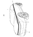
図1は本発明に係る実施形態の車両用灯具を備えた車両102を示す図であり、図1(a)は車両102を前方側から見た斜視図であり、図1(b)は車両102を後方側から見た斜視図である。
また、図2は図1(a)のA−A線に沿った一部断面図であり、図3は本発明に係る実施形態の車両用灯具の化粧部材10、第1導光体20及び第2導光体30を示す分解斜視図である。
FIG. 1 is a view showing a
2 is a partial cross-sectional view taken along the line AA of FIG. 1A, and FIG. 3 shows the
本実施形態の車両用灯具は、図1に示すように、搭載される車両102の周囲に沿って、車両102の回り360°のどの位置からでも視認可能に設けられ、車両102の状況に応じた発光状態の制御が行われる発光領域1を備えている。
As shown in FIG. 1, the vehicle lighting fixture of the present embodiment is provided so as to be visible from any position 360 ° around the
本実施形態では、発光領域1は、車両102の周囲に帯状に繋がって発光可能に設けられているが、必ずしも、帯状に繋がって発光可能である必要はなく、車両102の周囲の帯状の領域に発光する部分が適切な間隔で点在するようにしてもよく、この場合でも車両102の回り360°のどの位置からでも視認可能な発光領域1とすることができる。
In the present embodiment, the
また、本実施形態の車両用灯具は、車両102の前方側に設けられ、車両102の状況に応じた発光状態の制御が行われるフロント発光領域2を備えており、フロント発光領域2の一部からは、運転者の操作に応じてハイビームやロービーム等が照射できるようになっている。
Further, the vehicle lighting equipment of the present embodiment is provided on the front side of the
さらに、本実施形態の車両用灯具は、車両102の後方側に設けられ、車両102の状況に応じた発光状態の制御が行われるリア発光領域3を備えており、リア発光領域3は、少なくとも一部がテールランプやストップランプ等の機能を果たすようになっている。
Further, the vehicle lighting equipment of the present embodiment includes a rear
そして、発光領域1は、車両102の左右側においては、サイドウインドの下端の近くを前後方向に延在するように設けられ、車両102の前側においては、フロント発光領域2の上側の外周の一部に沿って延在するように設けられ、車両102の後側においては、リア発光領域3の上側の外周の一部に沿って延在するように設けられる。
The
このように、発光領域1の設けられる位置が高めの位置に設定されることで視認性を高めることができる。
例えば、車両102の左右側において、発光領域1がドアの下端側にあると、車両102の横に停車している他の車両や車両102と並走している他の車両からは、発光領域1を視認することが難しいが、本実施形態のように、サイドウインドの下端の近く設けられている場合には、良好に視認することが可能である。
In this way, the visibility can be improved by setting the position where the
For example, on the left and right sides of the
また、発光領域1は、フロント発光領域2及びリア発光領域3との区別がつき易く、車両102の周囲に沿って設けられたときにシャープな意匠性が得られることを考慮して、鉛直方向の幅が100.0mm以内にされており、本実施形態では、フロント発光領域2及びリア発光領域3の鉛直方向の最大幅が110.0mm以上であるのに対して、発光領域1の鉛直方向の最大幅が60.0mm以下にされている。
Further, the
なお、発光領域1の鉛直方向の幅は、本実施形態では最大の部分で約50.0mmとされ、最小の部分で約30.0mmとされており、車両102の周方向のどの位置においてもほぼ30.0mm以上50.0mm以下に収まるものになっている。
In the present embodiment, the width of the
さらに、発光領域1、フロント発光領域2及びリア発光領域3の一体感が得られるように、フロント発光領域2の左右側面側になる部分の形状を後方側に向かって鉛直方向の幅が小さくなるものとし、フロント発光領域2の後方側端部において、発光領域1とフロント発光領域2が段差なく繋がっているものとするとともに、リア発光領域3の左右側面側になる部分の形状を前方側に向かって鉛直方向の幅が小さくなるものとし、リア発光領域3の前方側端部において、発光領域1とリア発光領域3が段差なく繋がるようにしている。
Further, the width of the portion of the front
次に、発光領域1、フロント発光領域2及びリア発光領域3を発光させるための構成の一例について図2及び図3を参照しながら説明する。
なお、以下では、フロント側の構成、つまり、車両102の周方向で見て、リング状の発光領域1とフロント発光領域2が重なる部分の構成を例に挙げて説明を行うが、リア側の構成、つまり、車両102の周方向で見て、リング状の発光領域1とリア発光領域3が重なる部分の構成も同様の構成であるため、以下ではリア側の構成については詳細な説明を省略する。
Next, an example of the configuration for causing the
In the following description, the configuration on the front side, that is, the configuration of the portion where the ring-shaped
また、図1では、図示が省略されているが、車両102の左右側面にはドアがあるので、その部分の発光領域1は、フロント側の構成で説明する発光領域1に対応する構成がドアごとに設けられるだけであるため、以下では、この部分の構成についても詳細な説明を省略する。
Further, although not shown in FIG. 1, since there are doors on the left and right side surfaces of the
図2に示すように、本実施形態の車両用灯具は、化粧部材10と、第1出射面21側が化粧部材10に近接して配置された第1導光体20と、第2出射面31側が化粧部材10に近接して配置されるとともに、第2出射面31側が第1出射面21側と近接して配置される第2導光体30と、を備えている。
As shown in FIG. 2, the vehicle lighting fixture of the present embodiment includes a
なお、本実施形態では、化粧部材10は、化粧部材10の内側面12(第1出射面21及び第2出射面31に向く面)が第1出射面21及び第2出射面31にほぼ接触するように配置されている。
In the present embodiment, in the
そして、第1導光体20よりも内側には、第1ベース部B1が配置されており、その第1ベース部B1の第1導光体20に向く表面上に第1導光体20の第1入射面22に向けて光を照射する第1発光部25が設けられている。
The first base portion B1 is arranged inside the first
第1発光部25は、第1基板23と、その第1基板23上に第1入射面22に沿って複数設けられた第1発光チップ24と、を備えており、本実施形態では、第1発光部25の発光色として多彩な発光色が選択できるように、第1発光チップ24に光の三原色に対応した発光素子をパッケージ化し、3原色の発光が可能なLEDを用いている。
The first
なお、本実施形態では、第1入射面22に沿って複数設けられた第1発光チップ24の列が鉛直方向に2列設けられるようになっているが、鉛直方向に何列設けるかは、第1入射面22の鉛直方向の幅に応じて適宜変更してよい。
In the present embodiment, a plurality of rows of the first
同様に、第2導光体30よりも内側には、第2ベース部B2が配置されており、その第2ベース部B2の第2導光体30に向く表面上に第2導光体30の第2入射面32に向けて光を照射する第2発光部35が設けられている。
Similarly, the second base portion B2 is arranged inside the second
この第2発光部35も、第2基板33と、その第2基板33上に第2入射面32に沿って複数設けられた第2発光チップ34と、を備えており、本実施形態では、第1発光部25と同様に、発光色として多彩な発光色が選択できるように、第2発光チップ34に光の三原色に対応した発光素子をパッケージ化し、3原色の発光が可能なLEDを用いている。
The second
なお、本実施形態では、第2入射面32に沿って複数設けられた第2発光チップ34の列が鉛直方向に4列設けられるようになっているが、鉛直方向に何列設けるかは、第2入射面32の鉛直方向の幅に応じて適宜変更してよい。
In the present embodiment, a plurality of rows of the second
そして、本実施形態の車両用灯具は、第1導光体20と第2導光体30の間に配置され、第1導光体20又は第2導光体30内を導光する光が第2導光体30又は第1導光体20に漏洩するのを抑制する光遮断部40を有している。
The vehicle lighting fixture of the present embodiment is arranged between the first
例えば、光遮断部40は、図3に示すように、第1導光体20と第2導光体30の間に遮光テープ、遮光塗料の遮光膜、反射テープ及び反射塗料の反射膜等を設けることで構成することができる。
For example, as shown in FIG. 3, the
また、第1導光体20と第2導光体30の間に、それらより十分に屈折率の低い層を設けることでも光遮断部40を構成することができる。
ただし、屈折率差を利用する場合、物理的に光を遮断するテープや塗料に比べ、光を遮断する遮断力が弱くなるため、光遮断部40は、遮光テープ、遮光塗料の遮光膜、反射テープ及び反射塗料の反射膜等を設けることで物理的に光を遮断するように構成するのが好ましい。
Further, the
However, when the difference in refractive index is used, the blocking force for blocking light is weaker than that of a tape or paint that physically blocks light. It is preferable to provide a tape, a reflective film of a reflective paint, or the like so as to physically block light.
そして、本実施形態では、光遮断部40は、第1導光体20及び第2導光体30の双方に、直接、接触するように設けられており、光遮断部40をインサート部材として二色成形すれば、光遮断部40、第1導光体20及び第2導光体30を一体成形したものとすることが可能であり、製造コストを低減することができる。
Then, in the present embodiment, the
そして、光遮断部40を第1導光体20及び第2導光体30の双方に、直接、接触させるようにすることで、第1導光体20からの光で形成される発光領域1と第2導光体30からの光で形成されるフロント発光領域2が分離せず、良好な一体感が得られる。
Then, by bringing the
また、本実施形態では、化粧部材10は、厚みが3.0〜3.5mm程度と薄くしており、化粧部材10を光が透過するときに鉛直方向に光が広がらないで出射する。
なお、このことから化粧部材10の厚みは10.0mm以下であることが好ましく、さらに、5.0mm以下であることがより好ましい。
Further, in the present embodiment, the
From this, the thickness of the
さらに、本実施形態では、化粧部材10は、光を前方に照射する外面11から第1出射面21及び第2出射面31までの距離が約3.5mmとなるように設けられており、第1出射面21及び第2出射面31から外面11に至るまでに光が鉛直方向に広がることがない。
Further, in the present embodiment, the
このため、化粧部材10の外面11から前方側に照射される光の状態は、第1出射面21及び第2出射面31から化粧部材10に向けて照射された状態とほぼ同じ状態のままにすることができる。
Therefore, the state of the light emitted from the
なお、このように、第1出射面21及び第2出射面31から化粧部材10に向けて照射された状態とほぼ同じ状態のまま化粧部材10から光が前方側に照射されるようにするために、化粧部材10は、光を前方側に照射する外面11から第1出射面21及び第2出射面31までの距離が15.0mm以内になるように設けられていることが好ましく、さらに、10.0mm以内になるように設けられていることが好ましく、5.0mm以内になるように設けられていることが最も好ましい。
In this way, the light is emitted from the
そして、第1発光部25から第1導光体20の第1入射面22に向けて光を照射すると、その照射された光が、光遮断部40によって、第2導光体30側に漏洩しないように第1導光体20内を導光し、化粧部材10を介して前方側に照射され、第2導光体30を導光する光とほとんど混色していない状態の光によってリング状の発光領域1が発光する。
Then, when light is irradiated from the first
同様に、第2発光部35から第2導光体30の第2入射面32に向けて光を照射すると、その照射された光が、光遮断部40によって、第1導光体20側に漏洩しないように第2導光体30内を導光し、化粧部材10を介して前方側に照射され、第1導光体20を導光する光とほとんど混色していない状態の光によってフロント発光領域2が発光する。
Similarly, when light is irradiated from the second
このため、発光領域1とフロント発光領域2との境界で光の混色が発生し、狙った発光色にならないということを回避することができる。
なお、リア発光領域3でも、フロント発光領域2と同様に構成することで、発光領域1とリア発光領域3との境界で光の混色が発生し、狙った発光色にならないということを回避することができる。
Therefore, it is possible to avoid that the color mixing of light occurs at the boundary between the light
By configuring the rear
一方、化粧部材10が、いわゆるアウターレンズのように、内部構造が素通しで見えるものとしてしまうと、発光領域1及びフロント発光領域2(リア発光領域3も同様)が発光していないときに、第1導光体20、光遮断部40及び第2導光体30の間の境目等が見えることになり、一体感のないものとなってしまう。
On the other hand, if the
そこで、本実施形態では、化粧部材10が、第1出射面21及び第2出射面31から照射される光を透過できる透明度を有しているとともに、第1導光体20、光遮断部40及び第2導光体30の状態が透けて見えない程度の透明度を有しているものとすることで、発光領域1及びフロント発光領域2(リア発光領域3も同様)が発光していないときに化粧部材10だけが視認され、それらの発光領域が一体で形成されているように見えるようにしている。
Therefore, in the present embodiment, the
具体的には、化粧部材10を無色透明にするのではなく、乳白色やスモーク色等の色にして、色の濃さの状態によって、上述のような透明度になるように設定すればよい。
Specifically, the
また、別の方法としては、化粧部材10の内側面12(第1出射面21及び第2出射面31に向く面)にシボ又は微細プリズムを形成し、そのシボの状態又は微細プリズムの状態によって、いわゆる、すりガラスのような状態とするようにして、上述のような透明度になるように設定すればよい。
Alternatively, as another method, a grain or a fine prism is formed on the inner surface 12 (the surface facing the
なお、化粧部材10の外面11にシボ又は微細プリズムを形成することで、上述のような透明度にすることは可能であるが、そうすると、ザラザラ感が視認されることになるため、シボ又は微細プリズムを形成することで透明度を設定する場合には、化粧部材10の内側面12にシボ又は微細プリズムを形成することが好ましい。
It is possible to obtain the above-mentioned transparency by forming a grain or a fine prism on the
そして、先にも少し触れたが、車両102の左右側面のドアの部分には、フロント発光領域2及びリア発光領域3は設けられないため、この部分は、発光領域1だけとなる。
したがって、ドアごとに第1導光体20、第1発光部25及び化粧部材10を設けるようにして、発光領域1を構成すればよく、この場合、全体で見れば、第1導光体20が搭載される車両102の外周に沿ったリング状に配置されるとともに、化粧部材10が第1導光体20に沿ったリング状に配置されることになる。
And, as mentioned earlier, since the front
Therefore, the
そして、そのように第1導光体20及び化粧部材10をリング状に配置すれば、第1導光体20から化粧部材10に向けて照射される光が車両102の回りのいずれの位置からも目視可能であり、視認性の高い発光領域1となる。
Then, if the first
なお、この部分(左右側面のドアの部分)の化粧部材10は、第1導光体20と光遮断部40及び第2導光体30との境目を見せないためではなく、フロント側及びリア側と同じ化粧部材10を用いることで全体の一体感を得ることが主な目的であり、また、化粧部材10を設けておくことで、第1発光部25の構成が視認されるようなことを回避することも可能となる。
The
次に、上記のような構成を有する車両用灯具の車両102の状況に応じた発光状態の制御について説明する。
Next, the control of the light emitting state according to the situation of the
(状況1)
車両102の状況が、これから発進しようとしている場合、つまり、車両102が停止中で、かつ、ブレーキ動作中であるとともにシフトの状態が発進モードであるドライブに変更された状況の場合、発光状態の制御として、図4に示すように、フロント発光領域2の前方側中央を除く一部C1が点滅する制御が行われる。
(Situation 1)
When the situation of the
例えば、この点滅制御は、フロント発光領域2の通常時の発光強度である第1発光強度の点灯と、第1発光強度よりも高い発光強度である第2発光強度の点灯と、を数回繰り返すことで行われる。
For example, this blinking control repeats lighting of the first light emission intensity, which is the normal light emission intensity of the front
つまり、点灯と消灯を繰り返しているのではなく、点灯時の発光強度を変化させる点滅になっており、消灯を行わないため、車両102の前方側の視認性を低下させることなく、他者(歩行者、他車の運転者等)に車両102がこれから動き出すことを知らせることができる。
That is, instead of repeating turning on and off, the blinking changes the light emission intensity at the time of turning on, and since the light is not turned off, the visibility of the front side of the
(状況2)
車両102の状況が、歩行者に車両102の前方を横断することを促す状況の場合、発光状態の制御として、発光領域1の全体を点滅させるとともに、図5に示すように、フロント発光領域2の一部(黒塗り部分参照)を消灯させるとともに、例えば、歩行者が図5の右側から左側に向かって横断する場合、その消灯部分が、順次、図5に示すD1→D2→D3→・・・・→DNというように、横断方向に動く制御が行われる。
(Situation 2)
When the situation of the
したがって、発光領域1の全体の点滅により、車両102が停止していることを歩行者に強く印象付けるだけでなく、フロント発光領域2の発光状態の制御により、その車両102の停止が、歩行者を先に横断させるための停止であることを歩行者に的確に伝えることができる。
Therefore, not only the pedestrian is strongly impressed that the
例えば、このような発光状態の制御は、運転者の操作によって行うようにしてもよく、最近では、車両102にカメラや人を検知するセンサ等が搭載されているため、車両102が歩行者を横断させるために停止していることをカメラの画像やセンサの値等から制御部に求めさせて自動で行わせるようにしてもよい。
For example, such control of the light emitting state may be performed by the operation of the driver. Recently, since the
(状況3)
車両102の状況が、路肩に停止中で、かつ、車両102の前方を横断中の歩行者がいる状況の場合、発光状態の制御として、例えば、図6の左側の車両102の図において、歩行者が右側から左側に横断している場合、歩行者の横断開始側(図6の左図の右側)と反対側(図6の左図の左側及び図6の右図の右側)に位置する側のフロント発光領域2の一部C3及びリア発光領域3の一部C3を点滅する制御が行われる。
(Situation 3)
When the situation of the
具体的には、このときの点滅制御として、フロント発光領域2では、フロント発光領域2の通常時の発光強度である第1発光強度での点灯と消灯が繰り返し行われ、リア発光領域3では、リア発光領域3の通常時のテールランプとしての発光強度である第3発光強度での点灯と消灯が繰り返し行われる。
Specifically, as the blinking control at this time, in the front
このように、車両102の前方を横断しようとする歩行者がいることを後続車等に知らせることで、車両102の影からの歩行者の飛び出しによる事故を未然に防止することができる。
In this way, by notifying the following vehicle or the like that there is a pedestrian trying to cross the front of the
例えば、このような発光状態の制御は、運転者の操作によって行うようにしてもよく、車両102に搭載されているカメラや人を検知するセンサ等を利用して、カメラの画像やセンサの値等から制御部に状況を求めさせて自動で行うようにしてもよい。
For example, such control of the light emitting state may be performed by the operation of the driver, and the image of the camera or the value of the sensor may be used by using a camera mounted on the
(状況4)
車両102の状況が、後続車が接近してくる状況の場合、発光状態の制御として、テールランプとして機能するように発光するリア発光領域3の全体を点滅する制御が行われる。
なお、必ずしも、リア発光領域3の全体が点滅しなければならないわけではなく、リア発光領域3の少なくとも一部を点滅する制御であってもよい。
(Situation 4)
When the situation of the
It should be noted that the entire rear
例えば、リア発光領域3の通常時のテールランプとしての発光強度である第3発光強度での点灯と、第3発光強度よりも高く、ストップランプとしての発光強度である第4発光強度よりも低い発光強度である第5発光強度の点灯と、を繰り返すようにする点滅制御が行われる。
For example, lighting at the third emission intensity, which is the emission intensity of the rear
そして、その点滅制御では、点滅の速度が、後続車の距離と速度に基づき、変更される。
具体的には、後続車の速度が速く、且つ、距離が近いほど、点滅速度を速くするように、点滅の速度が変更されるようにして、衝突防止のアラートを行う。
Then, in the blinking control, the blinking speed is changed based on the distance and speed of the following vehicle.
Specifically, a collision prevention alert is issued by changing the blinking speed so that the blinking speed becomes faster as the speed of the following vehicle is faster and the distance is shorter.
例えば、このような発光状態の制御は、車両102に搭載されている後続車との車間距離を計測するセンサ等を利用して、そのセンサの値から後続車の距離と速度を制御部に求めさせて自動で行うようにすればよい。
For example, in such control of the light emitting state, the distance and speed of the following vehicle are obtained from the control unit from the value of the sensor by using a sensor or the like that measures the distance between the following vehicle and the following vehicle mounted on the
(状況5)
車両102の状況が、自動モードで駐車を行う状況の場合、発光状態の制御として、発光領域1の全体を、いわゆるハザードランプのような点滅速度の速い点滅周期で点滅させるとともに、図7に示すように、リア発光領域3の左右中央側の一部C5を赤以外の発光色(例えば、白)で発光させる制御が行われる。
(Situation 5)
When the
なお、発光領域1の全体を点滅させるのに限らず、少なくとも一部を点滅させるようにしてもよいが、発光領域1の全体を点滅させることで、車両102の全周囲の他者に好適に報知することができるため、発光領域1の全体を点滅させることが好ましい。
The entire
また、リア発光領域3の左右中央側の一部を赤以外の発光色(例えば、白)で発光させることで、一般に、赤色に発光するリア発光領域3が異なる色で発光することになるため、車両102が後退してくることを車両102の後方側にいる他者が認知し易い。
Further, by causing a part of the rear
例えば、このような発光状態の制御は、運転者によって、自動モードで駐車させる操作が行われたことに基づいて行うようにすればよい。
また、車両102が自動運転である場合には、自動運転を行っている制御部の指示に従って行うようにすればよい。
For example, such control of the light emitting state may be performed based on the operation of parking in the automatic mode by the driver.
Further, when the
(状況6)
車両102の状況が、自動運転モードに切り替える状況の場合、発光状態の制御として、発光領域1の全体を点滅させた後に、自動運転モードを知らせる点灯色(例えば、青)として発光領域1の全体を点灯する制御が行われる。
(Situation 6)
When the situation of the
このように点滅によって、例えば、後続車の運転者の注意を引き、そう上で自動運転の点灯色に変化するため、車両102が自動運転モードに移行することを、後続車の運転者が良好に認識することができる。 By blinking in this way, for example, the driver of the following vehicle is attracted to the attention of the driver of the following vehicle, and then the lighting color of the automatic driving is changed. Can be recognized.
例えば、このような発光状態の制御は、運転者によって、自動運転に切り替えるための操作が行われたことに基づいて行うようにすればよい。 For example, such control of the light emitting state may be performed based on the operation for switching to the automatic operation by the driver.
(状況7)
車両102の状況が、右左折を行う状況の場合、発光状態の制御として、例えば、図8において、車両102が左折しようとしている場合、左折しようとする側(車両102の左側)の発光領域1のうち、前方側の前方側領域C71と後方側の後方側領域C72を点滅させるとともに、前方側領域C71と後方側領域C72の間にある中間領域C73では、後方側から前方側に向かって発光部分が移動する制御が行われる。
(Situation 7)
When the situation of the
このように、前方側領域C71及び後方側領域C72では、通常のターンランプと同様の発光制御が行われるが、中間領域C73においては、光が走るような演出が行われ、視認性を高めることができる。 In this way, in the front side region C71 and the rear side region C72, light emission control similar to that of a normal turn lamp is performed, but in the intermediate region C73, an effect of running light is performed to improve visibility. Can be done.
例えば、このような発光状態の制御は、運転者の操作に基づいて行うようにすればよい。
また、車両102が自動運転である場合には、その自動運転の制御を行っている制御部の指示に基づいて行うようにすればよい。
For example, such control of the light emitting state may be performed based on the operation of the driver.
Further, when the
(状況8)
車両102の状況が、前方に歩行者を検知し、歩行者に近接していく状況の場合、発光状態の制御として、例えば、図9に示すように、発光領域1のうち、車両102と歩行者の距離、角度に応じて歩行者に対応する位置、つまり、領域C8のうち、歩行者に対応する位置となる一部を点滅させるとともに、その点滅させる部分を歩行者に対応して移動させる制御が行われる。
(Situation 8)
When the situation of the
例えば、発光領域1の通常の発光強度である第6発光強度での点灯と、第6発光強度の発光強度より高い発光強度である第7発光強度の点灯と、を繰り返す点滅を行いう点滅制御を行うようにすればよい。
For example, blinking control in which lighting at the sixth emission intensity, which is the normal emission intensity of the
そして、上述のように、車両102と歩行者の相対角に応じて、領域C8のうち点滅する部分が歩行者に対応して移動するようにされる。
Then, as described above, the blinking portion of the area C8 is made to move corresponding to the pedestrian according to the relative angle between the
例えば、このような発光状態の制御は、車両102に搭載されているカメラや人を検知するセンサ等を利用して、カメラの画像やセンサの値等から制御部が人を検知することで車両102と人の距離、角度に応じて人に対応する位置の点滅制御を開始させるとともに、制御部に車両102と人との相対角を求めさせて、その相対角の変化に合わせて領域C8のうち点滅する部分を移動させる、つまり、歩行者に対応して移動させる制御を行うようにすればよい。
For example, such control of the light emitting state is performed by using a camera mounted on the
(状況9)
車両102の状況が、ドアを開ける状況の場合、発光状態の制御として、例えば、車両102の左側のドアを開ける場合、図10に示すように、発光領域1のうち、その開けようとしているドア(左側のドア)に対応する領域の前方端部から後方側から視認できる位置までの領域C9を点滅する制御が行われる。
(Situation 9)
When the situation of the
具体的には、領域C9を飛び石状態で発光領域1の通常の発光強度である第6発光強度で点灯する部分と、第6発光強度の発光強度より高い発光強度である第7発光強度で点灯する部分と、があるように点灯させた後、第6発光強度で点灯している部分を第7発光強度で点灯させるとともに、第7発光強度で点灯している部分を第6発光強度で点灯させるようにして、飛び石状態の点灯状態が点滅するように行うとよい。
Specifically, the region C9 is lit in a stepping stone state at the sixth emission intensity, which is the normal emission intensity of the
例えば、このような制御は、ドアノブにタッチセンサのようなセンサを設けておき、車両102に乗車している者がドアノブに触れたことに基づいて行うようにすればよい。
For example, such control may be performed based on the fact that a sensor such as a touch sensor is provided on the doorknob and a person in the
(状況10)
車両102の状況が、セキュリティを開始する状況の場合、例えば、ドアの鍵を掛けたとき等のセキュリティを開始する状況の場合、発光状態の制御として、発光領域1の一部を点灯させるとともに、その点灯部分が発光領域1を周回するように移動させる制御が行われる。
例えば、このような制御は、ドアの鍵を掛けたことに基づいて行うようにすればよい。
(Situation 10)
When the situation of the
For example, such control may be based on locking the door.
以上のように、本実施形態の車両用灯具では、これまでにある灯具と異なり、発光領域1が車両102の回り360°のどの位置からでも視認可能に設けられているため、他者(歩行者、他車の運転者等)が伝達される情報を認知し易く、また、車両102のいろいろな状況に合わせた情報発信ができるため、他者との意思疎通性が高いものになっている。
As described above, in the vehicle lighting equipment of the present embodiment, unlike the conventional lighting equipment, the
以上、具体的な実施形態を基に本発明の説明を行ってきたが、本発明は、上記実施形態に限定されるものではなく、技術的思想を逸脱することのない変更や改良を行ったものも発明の技術的範囲に含まれるものであり、そのことは当業者にとって特許請求の範囲の記載から明らかである。 Although the present invention has been described above based on specific embodiments, the present invention is not limited to the above embodiments, and changes and improvements have been made without departing from the technical idea. Those are also included in the technical scope of the invention, which is clear to those skilled in the art from the description of the scope of claims.
1 発光領域
2 フロント発光領域
3 リア発光領域
10 化粧部材
11 外面
12 内側面
20 第1導光体
21 第1出射面
22 第1入射面
23 第1基板
24 第1発光チップ
25 第1発光部
30 第2導光体
31 第2出射面
32 第2入射面
33 第2基板
34 第2発光チップ
35 第2発光部
40 光遮断部
102 車両
B1 第1ベース部
B2 第2ベース部
1
Claims (5)
前記車両の前方側に設けられ、前記車両の状況に応じた発光状態の制御が行われるフロント発光領域と、
前記車両の後方側に設けられ、前記車両の状況に応じた発光状態の制御が行われるリア発光領域と、を備え、
前記発光領域は、
前記車両の左右側においては、サイドウインドの下端の近くを前後方向に延在するように設けられ、
前記車両の前側においては、前記フロント発光領域の外周の一部に沿って延在するように設けられ、
前記車両の後側においては、前記リア発光領域の外周の一部に沿って延在するように設けられ、
前記車両の状況が、歩行者に前記車両の前方を横断することを促す状況の場合、前記発光状態の制御として、前記発光領域の全体を点滅させるとともに、前記フロント発光領域の一部を消灯させるとともに、その消灯部分が横断方向に動く制御が行われることを特徴とする車両用灯具。 A light emitting region that is visibly provided from any position 360 ° around the vehicle along the circumference of the vehicle to be mounted and that controls the light emitting state according to the situation of the vehicle.
A front light emitting region provided on the front side of the vehicle and controlling the light emitting state according to the situation of the vehicle, and a front light emitting region.
It is provided on the rear side of the vehicle and includes a rear light emitting region in which the light emitting state is controlled according to the situation of the vehicle.
The light emitting region is
On the left and right sides of the vehicle, the side window is provided so as to extend in the front-rear direction near the lower end of the side window.
On the front side of the vehicle, it is provided so as to extend along a part of the outer circumference of the front light emitting region.
On the rear side of the vehicle, it is provided so as to extend along a part of the outer circumference of the rear light emitting region.
When the situation of the vehicle is a situation in which a pedestrian is urged to cross the front of the vehicle, as a control of the light emitting state, the entire light emitting area is blinked and a part of the front light emitting area is turned off. together, a vehicular lamp that off portion, characterized in Rukoto control is performed to move transversely.
前記車両の前方側に設けられ、前記車両の状況に応じた発光状態の制御が行われるフロント発光領域と、
前記車両の後方側に設けられ、前記車両の状況に応じた発光状態の制御が行われるリア発光領域と、を備え、
前記発光領域は、
前記車両の左右側においては、サイドウインドの下端の近くを前後方向に延在するように設けられ、
前記車両の前側においては、前記フロント発光領域の外周の一部に沿って延在するように設けられ、
前記車両の後側においては、前記リア発光領域の外周の一部に沿って延在するように設けられ、
前記車両の状況が、停止中で、かつ、前記車両の前方を横断中の歩行者がいる状況の場合、前記発光状態の制御として、前記歩行者の横断開始側と反対側に位置する側の前記フロント発光領域及び前記リア発光領域の一部を点滅する制御が行われることを特徴とする車両用灯具。 A light emitting region that is visibly provided from any position 360 ° around the vehicle along the circumference of the vehicle to be mounted and that controls the light emitting state according to the situation of the vehicle.
A front light emitting region provided on the front side of the vehicle and controlling the light emitting state according to the situation of the vehicle, and a front light emitting region.
It is provided on the rear side of the vehicle and includes a rear light emitting region in which the light emitting state is controlled according to the situation of the vehicle.
The light emitting region is
On the left and right sides of the vehicle, the side window is provided so as to extend in the front-rear direction near the lower end of the side window.
On the front side of the vehicle, it is provided so as to extend along a part of the outer circumference of the front light emitting region.
On the rear side of the vehicle, it is provided so as to extend along a part of the outer circumference of the rear light emitting region.
When the vehicle is stopped and there is a pedestrian crossing the front of the vehicle, the side located on the side opposite to the crossing start side of the pedestrian is used to control the light emitting state. the front light-emitting region and a vehicle lamp, wherein Rukoto control is performed to blink a part of the rear light emitting region.
Priority Applications (1)
| Application Number | Priority Date | Filing Date | Title |
|---|---|---|---|
| JP2017101503A JP6953790B2 (en) | 2017-05-23 | 2017-05-23 | Vehicle lighting |
Applications Claiming Priority (1)
| Application Number | Priority Date | Filing Date | Title |
|---|---|---|---|
| JP2017101503A JP6953790B2 (en) | 2017-05-23 | 2017-05-23 | Vehicle lighting |
Publications (2)
| Publication Number | Publication Date |
|---|---|
| JP2018197010A JP2018197010A (en) | 2018-12-13 |
| JP6953790B2 true JP6953790B2 (en) | 2021-10-27 |
Family
ID=64662960
Family Applications (1)
| Application Number | Title | Priority Date | Filing Date |
|---|---|---|---|
| JP2017101503A Active JP6953790B2 (en) | 2017-05-23 | 2017-05-23 | Vehicle lighting |
Country Status (1)
| Country | Link |
|---|---|
| JP (1) | JP6953790B2 (en) |
Families Citing this family (7)
| Publication number | Priority date | Publication date | Assignee | Title |
|---|---|---|---|---|
| CN113226848A (en) * | 2018-12-28 | 2021-08-06 | 株式会社小糸制作所 | Vehicle lamp |
| DE102019108312A1 (en) * | 2019-03-29 | 2020-10-01 | HELLA GmbH & Co. KGaA | Communication light device for vehicles |
| US12012114B2 (en) | 2019-11-20 | 2024-06-18 | Hyundai Mobis Co., Ltd. | Integration module for advanced driver assistance system |
| WO2021131789A1 (en) * | 2019-12-26 | 2021-07-01 | ソニーグループ株式会社 | Vehicle |
| JP7422038B2 (en) * | 2020-08-27 | 2024-01-25 | 本田技研工業株式会社 | mobile object |
| JP7488727B2 (en) * | 2020-08-27 | 2024-05-22 | 本田技研工業株式会社 | Mobile |
| KR20220086374A (en) | 2020-12-16 | 2022-06-23 | 현대모비스 주식회사 | Detachable driving guidance system and guiding method using the same |
Family Cites Families (12)
| Publication number | Priority date | Publication date | Assignee | Title |
|---|---|---|---|---|
| JPS5435876U (en) * | 1977-08-15 | 1979-03-08 | ||
| JPS6350747U (en) * | 1986-09-22 | 1988-04-06 | ||
| JPH0714942Y2 (en) * | 1988-10-31 | 1995-04-10 | 曙ブレーキ工業株式会社 | In-vehicle distance shortage warning device |
| JPH09132083A (en) * | 1995-11-10 | 1997-05-20 | Shiroki Corp | Door opening lamp built-in molding |
| DE19745993C2 (en) * | 1997-10-20 | 1999-11-11 | Daimler Chrysler Ag | Vehicle with electroluminescent light strip |
| JP2013116698A (en) * | 2011-12-05 | 2013-06-13 | Denso Corp | Control system |
| JP5853711B2 (en) * | 2012-01-12 | 2016-02-09 | マツダ株式会社 | Vehicle headlamp device |
| JP2015071340A (en) * | 2013-10-02 | 2015-04-16 | 本田技研工業株式会社 | Display device and display method for vehicle |
| JP6243288B2 (en) * | 2014-04-25 | 2017-12-06 | サカエ理研工業株式会社 | Light emitting device for vehicle |
| CA3000335A1 (en) * | 2015-09-30 | 2017-04-06 | Nissan Motor Co., Ltd. | Vehicle state indication system |
| JP6910953B2 (en) * | 2015-10-27 | 2021-07-28 | 株式会社小糸製作所 | Vehicle lighting device |
| JP6128263B2 (en) * | 2016-05-23 | 2017-05-17 | 株式会社デンソー | In-vehicle device |
-
2017
- 2017-05-23 JP JP2017101503A patent/JP6953790B2/en active Active
Also Published As
| Publication number | Publication date |
|---|---|
| JP2018197010A (en) | 2018-12-13 |
Similar Documents
| Publication | Publication Date | Title |
|---|---|---|
| JP6953790B2 (en) | Vehicle lighting | |
| CN105976641B (en) | Method for generating light distribution to issue driving instruction to the first vehicle | |
| JP6899100B2 (en) | Lighting equipment and vehicles | |
| CN104029632B (en) | vehicle with lamp | |
| JP7132945B2 (en) | Vehicle communication system, vehicle module, front composite module, and vehicle lighting | |
| KR20170063908A (en) | Symbol-displaying signaling device for a motor vehicle, and signal light equipped with such a lighting device | |
| US9869438B2 (en) | Dynamic logo projection system and method of using the same | |
| US7674026B2 (en) | Lamp system for a vehicle | |
| US20170210283A1 (en) | Display device of operation state of automobile brake | |
| CN110997407A (en) | Autonomous vehicle | |
| US20150239390A1 (en) | Illuminated Emblem | |
| JP7137581B2 (en) | Mobile display device | |
| KR101295825B1 (en) | Position Lamp and Turn Signal Lamp for Vehicle | |
| JP7213091B2 (en) | vehicle lamp | |
| WO2017051558A1 (en) | Motorcycle and motorcycle lighting device | |
| US9598001B2 (en) | Hazard beacon | |
| WO2010079716A1 (en) | Display device | |
| KR102695903B1 (en) | Lamp system for vehicle | |
| JP2020001454A (en) | Notification device | |
| JP7523462B2 (en) | Road surface drawing device | |
| JP2005112227A (en) | Operation status indication lamp of automobile | |
| KR101537490B1 (en) | Vehicle having signal lamp | |
| KR20200043280A (en) | Automobile | |
| KR101356684B1 (en) | Automotive head lamp | |
| JP5770687B2 (en) | Safety lamp |
Legal Events
| Date | Code | Title | Description |
|---|---|---|---|
| A621 | Written request for application examination |
Free format text: JAPANESE INTERMEDIATE CODE: A621 Effective date: 20200521 |
|
| A977 | Report on retrieval |
Free format text: JAPANESE INTERMEDIATE CODE: A971007 Effective date: 20210316 |
|
| A131 | Notification of reasons for refusal |
Free format text: JAPANESE INTERMEDIATE CODE: A131 Effective date: 20210323 |
|
| A521 | Request for written amendment filed |
Free format text: JAPANESE INTERMEDIATE CODE: A523 Effective date: 20210513 |
|
| TRDD | Decision of grant or rejection written | ||
| A01 | Written decision to grant a patent or to grant a registration (utility model) |
Free format text: JAPANESE INTERMEDIATE CODE: A01 Effective date: 20210831 |
|
| A61 | First payment of annual fees (during grant procedure) |
Free format text: JAPANESE INTERMEDIATE CODE: A61 Effective date: 20210913 |
|
| R150 | Certificate of patent or registration of utility model |
Ref document number: 6953790 Country of ref document: JP Free format text: JAPANESE INTERMEDIATE CODE: R150 |
|
| R250 | Receipt of annual fees |
Free format text: JAPANESE INTERMEDIATE CODE: R250 |