JP6514295B2 - Failure detection device, electric power steering device - Google Patents
Failure detection device, electric power steering device Download PDFInfo
- Publication number
- JP6514295B2 JP6514295B2 JP2017193045A JP2017193045A JP6514295B2 JP 6514295 B2 JP6514295 B2 JP 6514295B2 JP 2017193045 A JP2017193045 A JP 2017193045A JP 2017193045 A JP2017193045 A JP 2017193045A JP 6514295 B2 JP6514295 B2 JP 6514295B2
- Authority
- JP
- Japan
- Prior art keywords
- torque
- failure
- torque sensor
- continuous
- control unit
- Prior art date
- Legal status (The legal status is an assumption and is not a legal conclusion. Google has not performed a legal analysis and makes no representation as to the accuracy of the status listed.)
- Active
Links
- 238000001514 detection method Methods 0.000 title claims description 239
- 238000003745 diagnosis Methods 0.000 description 54
- 238000000034 method Methods 0.000 description 17
- 238000010586 diagram Methods 0.000 description 13
- 230000008859 change Effects 0.000 description 11
- 230000000737 periodic effect Effects 0.000 description 11
- 230000008569 process Effects 0.000 description 8
- 230000007423 decrease Effects 0.000 description 5
- 230000007935 neutral effect Effects 0.000 description 5
- 230000005540 biological transmission Effects 0.000 description 3
- 230000007246 mechanism Effects 0.000 description 3
- 230000000694 effects Effects 0.000 description 2
- 230000007274 generation of a signal involved in cell-cell signaling Effects 0.000 description 2
- 230000010355 oscillation Effects 0.000 description 2
- 230000009467 reduction Effects 0.000 description 2
- 238000005096 rolling process Methods 0.000 description 2
- 230000002159 abnormal effect Effects 0.000 description 1
- 230000009471 action Effects 0.000 description 1
- 238000004891 communication Methods 0.000 description 1
- 238000002405 diagnostic procedure Methods 0.000 description 1
- 238000004519 manufacturing process Methods 0.000 description 1
- 230000002093 peripheral effect Effects 0.000 description 1
- 230000004044 response Effects 0.000 description 1
Images


Classifications
-
- B—PERFORMING OPERATIONS; TRANSPORTING
- B62—LAND VEHICLES FOR TRAVELLING OTHERWISE THAN ON RAILS
- B62D—MOTOR VEHICLES; TRAILERS
- B62D5/00—Power-assisted or power-driven steering
- B62D5/04—Power-assisted or power-driven steering electrical, e.g. using an electric servo-motor connected to, or forming part of, the steering gear
- B62D5/0457—Power-assisted or power-driven steering electrical, e.g. using an electric servo-motor connected to, or forming part of, the steering gear characterised by control features of the drive means as such
- B62D5/0481—Power-assisted or power-driven steering electrical, e.g. using an electric servo-motor connected to, or forming part of, the steering gear characterised by control features of the drive means as such monitoring the steering system, e.g. failures
- B62D5/049—Power-assisted or power-driven steering electrical, e.g. using an electric servo-motor connected to, or forming part of, the steering gear characterised by control features of the drive means as such monitoring the steering system, e.g. failures detecting sensor failures
-
- B—PERFORMING OPERATIONS; TRANSPORTING
- B62—LAND VEHICLES FOR TRAVELLING OTHERWISE THAN ON RAILS
- B62D—MOTOR VEHICLES; TRAILERS
- B62D5/00—Power-assisted or power-driven steering
- B62D5/04—Power-assisted or power-driven steering electrical, e.g. using an electric servo-motor connected to, or forming part of, the steering gear
- B62D5/0457—Power-assisted or power-driven steering electrical, e.g. using an electric servo-motor connected to, or forming part of, the steering gear characterised by control features of the drive means as such
- B62D5/046—Controlling the motor
- B62D5/0463—Controlling the motor calculating assisting torque from the motor based on driver input
-
- B—PERFORMING OPERATIONS; TRANSPORTING
- B62—LAND VEHICLES FOR TRAVELLING OTHERWISE THAN ON RAILS
- B62D—MOTOR VEHICLES; TRAILERS
- B62D5/00—Power-assisted or power-driven steering
- B62D5/04—Power-assisted or power-driven steering electrical, e.g. using an electric servo-motor connected to, or forming part of, the steering gear
- B62D5/0457—Power-assisted or power-driven steering electrical, e.g. using an electric servo-motor connected to, or forming part of, the steering gear characterised by control features of the drive means as such
- B62D5/0481—Power-assisted or power-driven steering electrical, e.g. using an electric servo-motor connected to, or forming part of, the steering gear characterised by control features of the drive means as such monitoring the steering system, e.g. failures
- B62D5/0484—Power-assisted or power-driven steering electrical, e.g. using an electric servo-motor connected to, or forming part of, the steering gear characterised by control features of the drive means as such monitoring the steering system, e.g. failures for reaction to failures, e.g. limp home
-
- G—PHYSICS
- G01—MEASURING; TESTING
- G01L—MEASURING FORCE, STRESS, TORQUE, WORK, MECHANICAL POWER, MECHANICAL EFFICIENCY, OR FLUID PRESSURE
- G01L25/00—Testing or calibrating of apparatus for measuring force, torque, work, mechanical power, or mechanical efficiency
-
- G—PHYSICS
- G01—MEASURING; TESTING
- G01L—MEASURING FORCE, STRESS, TORQUE, WORK, MECHANICAL POWER, MECHANICAL EFFICIENCY, OR FLUID PRESSURE
- G01L3/00—Measuring torque, work, mechanical power, or mechanical efficiency, in general
- G01L3/02—Rotary-transmission dynamometers
- G01L3/04—Rotary-transmission dynamometers wherein the torque-transmitting element comprises a torsionally-flexible shaft
- G01L3/10—Rotary-transmission dynamometers wherein the torque-transmitting element comprises a torsionally-flexible shaft involving electric or magnetic means for indicating
Landscapes
- Engineering & Computer Science (AREA)
- Chemical & Material Sciences (AREA)
- Combustion & Propulsion (AREA)
- Transportation (AREA)
- Mechanical Engineering (AREA)
- Physics & Mathematics (AREA)
- General Physics & Mathematics (AREA)
- Power Steering Mechanism (AREA)
- Steering Control In Accordance With Driving Conditions (AREA)
Description
本発明は、故障検出装置、電動パワーステアリング装置に関する。 The present invention relates to a failure detection device and an electric power steering device.
例えば、特許文献1に記載の、電動パワーステアリング装置に組み込まれるトルク検出装置は、磁界の作用により電気的特性(抵抗)が変化するホール素子からなる感磁素子を2つ備えている。そして、これら2つの感磁素子は、入力軸(回転軸)に加わるトルクを検出するセンサとして機能する。
For example, the torque detection device incorporated in the electric power steering device described in
操舵トルクを安定的にかつ精度良く検出するためには、少なくとも2つのトルクセンサを備えていることが望ましい。これは、操舵トルクを検出可能なトルクセンサが2つある場合、2つのトルクセンサそれぞれから出力される出力値を比較することで2つのトルクセンサが正常であることを精度高く判断することが可能だからである。他方、2つのトルクセンサの内の一方のトルクセンサが故障した場合には、他方のトルクセンサが正常に動作していることを判断した上で、他方のトルクセンサから出力された出力値に応じて、モータアシストを継続することが望ましい。
本発明は、正常なトルクセンサが一つである場合においても、このトルクセンサが正常に動作していることを判断できる故障検出装置、電動パワーステアリング装置を提供することを目的とする。
In order to detect the steering torque stably and accurately, it is desirable to include at least two torque sensors. This is because, when there are two torque sensors that can detect the steering torque, it is possible to accurately determine that the two torque sensors are normal by comparing the output value output from each of the two torque sensors. That's why. On the other hand, if one of the two torque sensors fails, it is determined that the other torque sensor is operating normally, and the output value output from the other torque sensor is determined. It is desirable to continue motor assist.
An object of the present invention is to provide a failure detection device and an electric power steering device that can determine that the torque sensor is operating properly even when there is only one normal torque sensor.
かかる目的のもと完成させた本発明は、回転軸に印加されたトルクを2つのトルクセンサにて検出するトルク検出部の故障を検出する故障検出部と、モータの駆動を制御する制御部と、を備え、前記制御部は、前記トルク検出部が有する前記2つのトルクセンサの内の一方のトルクセンサが故障していることを検出した場合に、前記2つのトルクセンサの内の他方のトルクセンサにて検出可能なトルクを連続的に発生させる連続トルクを出力させ、前記故障検出部は、前記モータが前記連続トルクを出力した場合に、前記トルクセンサが検出する前記連続トルクに起因する振動のパターンによって前記他方のトルクセンサの故障を診断し、前記振動の1周期内で、前記他方のトルクセンサの出力値が、トルクがゼロである場合の出力値を跨らない場合に故障していると判断する故障検出装置である。 The present invention is based on the completion of such object is achieved by a failure detecting section detecting a failure of the torque detection unit that detects the applied torque to the rotation shaft at two torque sensors, control unit for controlling the driving of the motor And when the control unit detects that one of the two torque sensors included in the torque detection unit is broken, the other of the two torque sensors is detected. The continuous torque that continuously generates a torque detectable by the torque sensor is output, and the failure detection unit is caused by the continuous torque detected by the torque sensor when the motor outputs the continuous torque. The failure of the other torque sensor is diagnosed by the vibration pattern, and within one cycle of the vibration, the output value of the other torque sensor crosses the output value when the torque is zero. A failure detection device to determine that a failure in the case are.
本発明によれば、正常なトルクセンサが一つである場合においても、このトルクセンサが正常に動作していることを判断できる。 According to the present invention, even in the case where there is only one normal torque sensor, it can be determined that this torque sensor is operating normally.
以下、添付図面を参照して、本発明の実施の形態について詳細に説明する。
<第1の実施形態>
図1は、第1の実施形態に係る電動パワーステアリング装置100の概略構成を示す図である。
電動パワーステアリング装置100(以下、単に「ステアリング装置100」と称する場合もある。)は、車両の進行方向を任意に変えるためのかじ取り装置であり、本実施形態においては車両の一例としての自動車1に適用した構成を例示している。なお、図1は、自動車1を前方から見た図である。
Hereinafter, embodiments of the present invention will be described in detail with reference to the attached drawings.
First Embodiment
FIG. 1 is a view showing a schematic configuration of the electric
Electric power steering apparatus 100 (hereinafter sometimes referred to simply as "
ステアリング装置100は、自動車1の進行方向を変えるために運転者が操作する車輪(ホイール)状のステアリングホイール(ハンドル)101と、ステアリングホイール101に一体的に設けられたステアリングシャフト102とを備えている。また、ステアリング装置100は、ステアリングシャフト102と自在継手103aを介して連結された連結シャフト103と、この連結シャフト103と自在継手103bを介して連結されたピニオンシャフト106とを備えている。ピニオンシャフト106は、ステアリングホイール101の回転に連動して回転する。ピニオンシャフト106の下端部には、ピニオン106aが形成されている。
The
また、ステアリング装置100は、転動輪としての左側前輪151,右側前輪152それぞれに連結されたタイロッド104と、タイロッド104に連結されたラック軸105とを備えている。ラック軸105に形成されたラック歯105aと、ピニオンシャフト106に形成されたピニオン106aとがラック・ピニオン機構を構成する。
The
また、ステアリング装置100は、ピニオンシャフト106の捩れに基づいて、ステアリングホイール101に加えられた操舵トルクTを検出するトルク検出装置200を備えている。トルク検出装置200は、第1トルクセンサ201と、第2トルクセンサ202とを有している。第1トルクセンサ201及び第2トルクセンサ202は、磁歪に起因する磁気特性の変化に基づいてピニオンシャフト106の捩れに応じた操舵トルクTを検出する磁歪式のセンサであることを例示することができる。第1トルクセンサ201及び第2トルクセンサ202による操舵トルクTの検出のために、ピニオンシャフト106の外周面に磁歪膜が形成されている。なお、第1トルクセンサ201及び第2トルクセンサ202は、ホールIC、MR素子を用いる周知のトルクセンサであっても良い。以下、第1トルクセンサ201と第2トルクセンサ202とを総称して「トルクセンサ203」と称する場合がある。
The
また、ステアリング装置100は、ピニオンシャフト106を収納するステアリングギヤボックス107と、ステアリングギヤボックス107に支持された電動モータ110と、電動モータ110の駆動力を減速してピニオンシャフト106に伝達する減速機構111とを有している。減速機構111は、例えば、ピニオンシャフト106に固定されたウォームホイール(不図示)と、電動モータ110の出力軸に固定されたウォームギヤ(不図示)などから構成される。電動モータ110は、ピニオンシャフト106に回転駆動力を加えることにより、ラック軸105に左側前輪151,右側前輪152を転動させる駆動力(ラック軸力)を加える。本実施の形態に係る電動モータ110は、電動モータ110の回転角度であるモータ回転角度θmに連動した回転角度信号θmsを出力するレゾルバ120を有する3相ブラシレスモータである。
Further, the
また、ステアリング装置100は、電動モータ110の作動を制御する制御装置10を備えている。制御装置10には、上述したトルク検出装置200からの出力信号が入力される。また、制御装置10には、自動車1に搭載される各種の機器を制御するための信号を流す通信を行うネットワーク(CAN)を介して、自動車1の移動速度である車速Vcを検出する車速センサ170からの出力信号vなどが入力される。
The
以上のように構成されたステアリング装置100は、トルク検出装置200が検出した操舵トルクTに基づいて電動モータ110を駆動し、電動モータ110の駆動力(発生トルク)をピニオンシャフト106に伝達する。これにより、電動モータ110の発生トルクが、ステアリングホイール101に加える運転者の操舵をアシストする。このように、電動モータ110は、運転者のステアリングホイール101の操舵に対してアシスト力を付与する。
The
{制御装置}
次に、制御装置10について説明する。
図2は、制御装置10の概略構成図である。
制御装置10は、CPU、ROM、RAM、バックアップRAM等からなる算術論理演算回路である。
制御装置10には、上述した第1トルクセンサ201から出力される第1トルク検出信号TS1、第2トルクセンサ202から出力される第2トルク検出信号TS2、車速センサ170からの車速Vcに対応する車速信号vなどが入力される。
{Control device}
Next, the
FIG. 2 is a schematic configuration diagram of the
The
The
そして、制御装置10は、電動モータ110が供給するのに必要となる目標電流Itを算出(設定)する目標電流算出部20と、目標電流算出部20が算出した目標電流Itに基づいてフィードバック制御などを行う制御部30とを備えている。
また、制御装置10は、第1トルクセンサ201から出力される第1トルク検出信号TS1又は第2トルクセンサ202から出力される第2トルク検出信号TS2に基づいて操舵トルクに応じた値を出力すると共にトルク検出装置200の故障を診断する出力部80を備えている。
Then, the
Further, the
〔目標電流算出部〕
目標電流算出部20は、仮の目標電流である仮目標電流Itfを決定する仮目標電流決定部25と、出力部80がトルク検出装置200の故障を検出したか否かに応じて故障検出電流Ifを決定する故障検出電流決定部28と、最終的に電動モータ110に供給する目標電流Itを決定する最終目標電流決定部29とを備えている。
なお、目標電流算出部20には、出力部80から出力される後述するトルク信号Td、車速Vcに応じた車速センサ170からの出力信号などが入力される。
[Target current calculation unit]
The target
The target
仮目標電流決定部25は、トルク信号Tdと、車速センサ170からの出力信号vとに基づいて仮目標電流Itfを決定する。操舵トルクTがプラスである場合には仮目標電流Itfはプラス、操舵トルクTがマイナスである場合には仮目標電流Itfはマイナスとすることを例示することができる。なお、不感帯領域を設定することもできる。また、仮目標電流Itfは、操舵トルクTの絶対値が同じである場合には、車速Vcが低速であるほど仮目標電流Itfの絶対値が大きくなる。
Temporary target
故障検出電流決定部28については後で詳述する。
最終目標電流決定部29は、出力部80から第1トルクセンサ201及び第2トルクセンサ202が共に故障している旨の情報を取得していない場合には、仮目標電流決定部25にて決定された仮目標電流Itfと、故障検出電流決定部28にて決定された故障検出電流Ifとを加算した値を最終的な目標電流Itとして決定する。他方、最終目標電流決定部29は、出力部80から第1トルクセンサ201及び第2トルクセンサ202が共に故障している旨の情報を取得した場合には、目標電流Itをゼロとして決定する。
The failure detection
When the final target
目標電流算出部20は、仮目標電流決定部25、故障検出電流決定部28及び最終目標電流決定部29が、所定期間(例えば1ミリ秒)毎に出力部80や車速センサ170等の各種センサからの出力値を取得すると共に各処理を行い、所定期間毎に目標電流Itを算出する。
出力部80は、所定期間(例えば1ミリ秒)毎にトルク検出装置200からの出力値を取得すると共に各処理を行い、所定期間毎にトルク信号Tdやトルク検出装置200が故障している旨の信号等を出力する。
The target
The
ここで、ピニオンシャフト106の捩れ量が0の状態を中立状態(中立位置)とし、中立状態(中立位置)からのステアリングホイール101の右回転時におけるピニオンシャフト106の捩れが変化する方向をプラス(操舵トルクTがプラス)とする。また、中立状態からのステアリングホイール101の左回転時におけるピニオンシャフト106の捩れが変化する方向をマイナス(操舵トルクTがマイナス)とする。
そして、基本的に、トルク検出装置200にて検出された操舵トルクTがプラスであるときに、電動モータ110を右回転方向に回転させるように仮目標電流Itfが算出され、その仮目標電流Itfが流れる方向をプラスとする。つまり、基本的に、操舵トルクTがプラスのときに仮目標電流決定部25はプラスの仮目標電流Itfを決定し、電動モータ110を右回転方向に回転させる方向のトルクを発生させる。操舵トルクTがマイナスのときに仮目標電流決定部25はマイナスの仮目標電流Itfを決定し、電動モータ110を左回転方向に回転させる方向のトルクを発生させる。
Here, a state in which the amount of twist of the
Then, basically, when the steering torque T detected by the
〔制御部〕
制御部30は、電動モータ110の作動を制御するモータ駆動制御部(不図示)と、電動モータ110を駆動させるモータ駆動部(不図示)と、電動モータ110に実際に流れる実電流Imを検出するモータ電流検出部(不図示)とを有している。
モータ駆動制御部は、目標電流算出部20にて最終的に決定された目標電流Itと、モータ電流検出部にて検出された電動モータ110へ供給される実電流Imとの偏差に基づいてフィードバック制御を行うフィードバック(F/B)制御部(不図示)と、電動モータ110をPWM駆動するためのPWM(パルス幅変調)信号を生成するPWM信号生成部(不図示)とを有している。
[Control unit]
The motor drive control unit performs feedback based on the deviation between the target current It finally determined by the target
フィードバック制御部は、目標電流算出部20にて最終的に決定された目標電流Itとモータ電流検出部にて検出された実電流Imとの偏差を求める偏差演算部(不図示)と、その偏差がゼロとなるようにフィードバック処理を行うフィードバック(F/B)処理部(不図示)とを有している。
PWM信号生成部は、フィードバック制御部からの出力値に基づいて電動モータ110をPWM(パルス幅変調)駆動するためのPWM信号を生成し、生成したPWM信号を出力する。
The feedback control unit is a deviation calculation unit (not shown) for obtaining a deviation between the target current It finally determined by the target
The PWM signal generation unit generates a PWM signal for performing PWM (Pulse Width Modulation) driving of the
モータ駆動部は、所謂インバータであり、例えば、スイッチング素子として6個の独立したトランジスタ(FET)を備え、6個の内の3個のトランジスタは電源の正極側ラインと各相の電気コイルとの間に接続され、他の3個のトランジスタは各相の電気コイルと電源の負極側(アース)ラインと接続されている。そして、6個の中から選択した2個のトランジスタのゲートを駆動してこれらのトランジスタをスイッチング動作させることにより、電動モータ110の駆動を制御する。
モータ電流検出部は、モータ駆動部に接続されたシャント抵抗の両端に生じる電圧から電動モータ110に流れる実電流Imの値を検出する。
The motor drive unit is a so-called inverter, and includes, for example, six independent transistors (FETs) as switching elements, and three of the six transistors are connected between the positive side line of the power supply and the electric coil of each phase. The other three transistors are connected between the electrical coil of each phase and the negative side (ground) line of the power supply. Then, the drive of the
The motor current detection unit detects the value of the actual current Im flowing to the
〔出力部〕
出力部80は、トルク検出装置200が故障しているか否か、言い換えれば、第1トルクセンサ201と第2トルクセンサ202の少なくともいずれかが故障しているか否かを診断する一次故障診断部81を備えている。また、出力部80は、トルク検出装置200が故障していると一次故障診断部81が診断した場合に、第1トルクセンサ201、第2トルクセンサ202のどちらが故障しているかを特定すると共に、故障していない正常なトルクセンサ203が故障したか否かを診断する二次故障診断部82を備えている。また、出力部80は、故障診断結果に基づいて、第1トルクセンサ201から出力された第1トルク検出信号TS1か、第2トルクセンサ202から出力された第2トルク検出信号TS2かを、トルク信号Tdとして用いるのを切り替える切替部85を備えている。
[Output section]
The
《一次故障診断部》
一次故障診断部81には、第1トルクセンサ201から出力される第1トルク検出信号TS1、第2トルクセンサ202から出力される第2トルク検出信号TS2が入力される。そして、一次故障診断部81は、第1トルク検出信号TS1及び第2トルク検出信号TS2に基づいて、第1トルクセンサ201又は第2トルクセンサ202が故障しているか否かを診断する。故障診断方法については後で詳述する。
Primary Failure Diagnosis Unit
The first
〔一次故障診断〕
以下、一次故障診断部81が行う故障診断について説明する。
図3は、第1トルク検出信号TS1,第2トルク検出信号TS2の出力範囲を示す図である。以下、第1トルク検出信号TS1と第2トルク検出信号TS2とをまとめて「トルク検出信号TS」と称する場合もある。
第1トルク検出信号TS1は、図3に示すように、操舵トルクTの右方向への大きさが増加するのに伴って上昇すると共に、最大電圧VHiと最小電圧VLoとの間で変化する。第2トルク検出信号TS2は、図3に示すように、操舵トルクTの左方向への大きさが増加するのに伴って上昇すると共に、最大電圧VHiと最小電圧VLoとの間で変化する。最大電圧VHiは4.5V、最小電圧VLoは0.5Vであることを例示することができる。また、操舵トルクTがゼロ(中点)である場合には、第1トルク検出信号TS1及び第2トルク検出信号TS2は共に中点電圧Vcl(=(VHi+VLo)/2)である。
[Primary fault diagnosis]
Hereinafter, failure diagnosis performed by the primary
FIG. 3 is a diagram showing an output range of the first torque detection signal TS1 and the second torque detection signal TS2. Hereinafter, the first torque detection signal TS1 and the second torque detection signal TS2 may be collectively referred to as "torque detection signal TS".
As shown in FIG. 3, the first torque detection signal TS1 rises as the magnitude of the steering torque T in the right direction increases, and changes between the maximum voltage VHi and the minimum voltage VLo. As shown in FIG. 3, the second torque detection signal TS2 rises as the magnitude of the steering torque T in the left direction increases, and changes between the maximum voltage VHi and the minimum voltage VLo. It can be illustrated that the maximum voltage VHi is 4.5 V and the minimum voltage VLo is 0.5 V. When the steering torque T is zero (midpoint), both the first torque detection signal TS1 and the second torque detection signal TS2 are the midpoint voltage Vcl (= (VHi + VLo) / 2).
図4は、トルク検出装置200の故障検出範囲を示す図である。
トルク検出装置200に故障が生じた場合には、図4に示した故障検出範囲に入る。トルク検出装置200の故障としては、回路の固着故障、断線、信号異常故障であることを例示することができる。
第1トルクセンサ201及び第2トルクセンサ202が共に正常に作動している場合、第1トルク検出信号TS1と第2トルク検出信号TS2とを合計した合計電圧Vtは、常に所定電圧(VHi+VLo)(=2Vcl)になる(図4の実線参照)。
FIG. 4 is a diagram showing a failure detection range of the
If a failure occurs in the
When both the
一次故障診断部81は、第1トルク検出信号TS1と第2トルク検出信号TS2とを合計した合計電圧Vtが、所定電圧(VHi+VLo)を中心とする所定範囲内である場合には第1トルクセンサ201及び第2トルクセンサ202は正常であり、トルク検出装置200は正常であると診断する。他方、一次故障診断部81は、合計電圧Vtが、所定範囲から外れた場合に、第1トルクセンサ201又は第2トルクセンサ202が故障しており、トルク検出装置200は故障していると診断する。所定範囲は、図4に示すように、所定電圧(VHi+VLo)より低い下限基準値VL以上であって、所定電圧(VHi+VLo)より高い上限基準値VH以下の領域であることを例示することができる。
If the total voltage Vt obtained by summing the first torque detection signal TS1 and the second torque detection signal TS2 is within a predetermined range centered on the predetermined voltage (VHi + VLo), the primary
故障検出電流決定部28は、一次故障診断部81から第1トルクセンサ201及び第2トルクセンサ202が故障していない旨の信号を取得した場合(トルク検出装置200が故障した旨の信号を取得していない場合)には、故障検出電流Ifをゼロとする。他方、一次故障診断部81から第1トルクセンサ201又は第2トルクセンサ202が故障している旨の信号を取得した場合には、電動モータ110が振動を発生する強制振動発生電流を故障検出電流Ifとして決定する。強制振動発生電流は、正弦波状に正と負の値に周期的に変化する値であることを例示することができる。
The failure detection
以上のように構成された制御装置10において、トルク検出装置200が正常である場合、すなわち第1トルクセンサ201及び第2トルクセンサ202のいずれも正常である場合には、故障検出電流決定部28が故障検出電流Ifをゼロとする。その結果、目標電流算出部20は、仮目標電流決定部25にて決定された仮目標電流Itfを最終的な目標電流Itとして決定する。
一方、トルク検出装置200が故障している場合、すなわち第1トルクセンサ201と第2トルクセンサ202の少なくともいずれかが故障している場合には、故障検出電流決定部28が強制振動発生電流を故障検出電流Ifとして決定する。その結果、目標電流算出部20は、仮目標電流決定部25にて決定された仮目標電流Itfに故障検出電流If(強制振動発生電流)を加算した電流を最終的な目標電流Itとして決定する。
以下では、制御装置10が、トルク検出装置200が正常である場合に行う電動モータ110の駆動制御を「通常制御」と称し、トルク検出装置200が故障している場合に行う電動モータ110の駆動制御を「故障時制御」と称す。
In
On the other hand, when the
Hereinafter, the drive control of the
《二次故障診断部》
故障時制御において、仮目標電流Itfに故障検出電流Ifを加算すると、故障検出電流If(強制振動発生電流)相当分の電動モータ110の駆動トルクによりピニオンシャフト106が周期的に捩れる。そのため、トルクセンサ203が正常である場合には、故障検出電流If(強制振動発生電流)に起因するピニオンシャフト106の周期的な捩れを検出する。他方、トルクセンサ203が故障している場合には、故障検出電流If(強制振動発生電流)に起因するピニオンシャフト106の周期的な捩れを検出できない。
かかる事項に鑑み、出力部80の二次故障診断部82は、トルクセンサ203から取得する信号が、故障検出電流If(強制振動発生電流)に起因するピニオンシャフト106の周期的な捩れを反映している場合には、トルクセンサ203は正常であると判断し、反映していない場合には故障していると判断する。
<< Secondary Failure Diagnosis Unit >>
In the failure control, when the failure detection current If is added to the temporary target current Itf, the
In view of such matters, the secondary
〔二次故障診断〕
図5(a)は、故障時制御実行中の目標電流Itの一例を示す図である。図5(b)及び図5(c)は、トルクセンサ203から出力されるトルク検出信号TSの一例を示す図である。
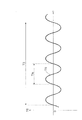
図5(a)では、故障時制御実行中において、仮目標電流Itfがゼロである場合、つまり目標電流Itが故障検出電流If(強制振動発生電流)と等しい場合を例示している。図5(a)に示すように、強制振動発生電流は、正弦波状に正と負の値に周期的に変化する値である。
図5(b)には、トルクセンサ203が、故障検出電流If(強制振動発生電流)に起因するピニオンシャフト106の周期的な捩れを反映している場合のトルク検出信号TSの一例を示している。言い換えれば、図5(b)には、電動モータ110が連続トルク(故障検出電流If(強制振動発生電流)に起因するトルク)を出力した場合に、トルクセンサ203が検出する連続トルクに起因する振動のパターンの一例を示している。
図5(c)には、トルクセンサ203が、故障検出電流If(強制振動発生電流)に起因するピニオンシャフト106の周期的な捩れを反映していない場合のトルク検出信号TSの一例を示している。
[Secondary fault diagnosis]
FIG. 5A is a diagram showing an example of the target current It during execution of failure control. FIGS. 5B and 5C are diagrams showing an example of the torque detection signal TS output from the
FIG. 5A exemplifies a case where the temporary target current Itf is zero during execution of failure control, that is, the target current It is equal to the failure detection current If (forced vibration generation current). As shown in FIG. 5 (a), the forced vibration generating current is a value that periodically changes to positive and negative values in a sinusoidal manner.
FIG. 5B shows an example of the torque detection signal TS when the
FIG. 5C shows an example of the torque detection signal TS when the
図6(a)は、故障時制御実行中の仮目標電流Itfの変化の一例を示す図である。図6(b)は、故障時制御実行中の故障検出電流If(強制振動発生電流)の変化を示す図である。図6(c)は、トルクセンサ203から出力されるトルク検出信号TSの一例を示す図である。
図6(a)では、仮目標電流Itfの想定される最大値Maxf及び最小値Minf(|Maxf|=|Minf|)を、それぞれ正の頂点、負の頂点とする正弦波状の仮目標電流Itfを例示している。
第1の実施形態に係る強制振動発生電流(故障検出電流If)は、正弦波状に正と負の値に周期的に変化する値であって、振幅が、最大値Maxfの2倍よりも大きな値となる。それゆえ、仮目標電流Itfの値に関わらず、強制振動発生電流を1周期Tif分加算(出力)した場合には、正常なトルクセンサ203から出力されるトルク検出信号TSは、中点電圧Vclを跨ぐ。例えば、トルク検出信号TSの符号を、中点電圧Vclよりも高い場合(Vcl<TS≦VHi)をプラス、中点電圧Vclよりも低い場合(VLo≦TS<Vcl)をマイナスとした場合に、トルク検出信号TSの符号がプラスからマイナスへ、又はマイナスからプラスへ変化する。
FIG. 6A is a diagram showing an example of the change of the temporary target current Itf during the failure control execution. FIG. 6B is a diagram showing a change in the failure detection current If (forced vibration generation current) during failure control execution. FIG. 6C shows an example of the torque detection signal TS output from the
In FIG. 6A, a sinusoidal temporary target current Itf in which the assumed maximum value Maxf and the minimum value Minf (| Maxf | = | Minf |) of the temporary target current Itf are respectively a positive vertex and a negative vertex. Is illustrated.
The forced vibration generation current (fault detection current If) according to the first embodiment is a value that periodically changes to positive and negative values in a sine wave shape, and the amplitude is larger than twice the maximum value Maxf. It becomes a value. Therefore, regardless of the value of the temporary target current Itf, when the forced vibration generation current is added (outputted) for one cycle Tif, the torque detection signal TS output from the
二次故障診断部82は、故障検出電流決定部28が故障検出電流Ifを強制振動発生電流としている期間における強制振動発生電流の1周期Tif間にトルクセンサ203から出力されるトルク検出信号TSが中点電圧Vclを跨ぐか否かに基づいて、トルクセンサ203の故障を診断する。言い換えれば、二次故障診断部82は、1周期Tif間にトルク検出信号TSの符号が変化したか否かに基づいて、トルクセンサ203の故障を診断する。例えば、図6(c)のA期間に示すように、期間Tif間にトルクセンサ203から出力されるトルク検出信号TSの符号が変化した場合には、二次故障診断部82は、トルクセンサ203からの出力値が強制振動発生電流(故障検出電流If)に起因するピニオンシャフト106の捩れを正確に反映しているとして、トルクセンサ203は正常であると判断する。言い換えれば、図6(c)のA期間には、電動モータ110が連続トルク(故障検出電流If(強制振動発生電流)に起因するトルク)を出力した場合に、正常なトルクセンサ203が検出する、連続トルクに起因する振動のパターンの一例を示している。一方、図6(c)のB期間に示すように、期間Tif間にトルクセンサ203から出力されるトルク検出信号TSの符号が変化しなかった場合には、二次故障診断部82は、トルクセンサ203からの出力値が強制振動発生電流(故障検出電流If)に起因するピニオンシャフト106の捩れを正確に反映していないとして、トルクセンサ203は故障していると判断する。言い換えれば、図6(c)のB期間には、電動モータ110が連続トルク(故障検出電流If(強制振動発生電流)に起因するトルク)を出力した場合に、故障しているトルクセンサ203が検出する、連続トルクに起因する振動のパターンの一例を示している。期間Tif間にトルクセンサ203から出力されるトルク検出信号TSの符号が変化しない場合には、トルクセンサ203にオフセット故障が生じている可能性があるからである。また、故障判断にあたって、トルク検出信号TSの符号が変化しなかった回数を所定期間カウントし、そのカウント値が一定の値を超えた場合に故障していると判断しても良い。
The secondary
図7(a)は、故障時制御実行中の仮目標電流Itfの変化の一例を示す図である。図7(b)は、トルクセンサ203から出力されるトルク検出信号TSの一例を示す図である。図7(a)では、仮目標電流Itfの想定される最大値Maxfの1/2及び最小値Minfの1/2を、それぞれ正の頂点、負の頂点とする正弦波状の仮目標電流Itfを例示している。
また、二次故障診断部82は、故障検出電流決定部28が故障検出電流Ifを強制振動発生電流としている時(故障時制御実行時)にトルクセンサ203から出力されるトルク検出信号TSの振幅Aに基づいてトルクセンサの故障を診断する。例えば、図7(b)のC期間に示すように、トルク検出信号TSの振幅Aが予め定められた基準振幅A0以上である場合には、二次故障診断部82は、トルクセンサ203からの出力値が強制振動発生電流に起因するピニオンシャフト106の捩れを正確に反映しているとして、トルクセンサ203は正常であると判断する。言い換えれば、図7(b)のC期間には、電動モータ110が連続トルク(故障検出電流If(強制振動発生電流)に起因するトルク)を出力した場合に、正常なトルクセンサ203が検出する、連続トルクに起因する振動のパターンの一例を示している。一方、例えば、図7(b)のD期間に示すように、トルク検出信号TSの振幅Aが基準振幅A0未満となった場合には、二次故障診断部82は、トルクセンサ203からの出力値が強制振動発生電流に起因するピニオンシャフト106の捩れを正確に反映していないとして、トルクセンサ203は故障していると判断する。言い換えれば、図7(b)のD期間には、電動モータ110が連続トルク(故障検出電流If(強制振動発生電流)に起因するトルク)を出力した場合に、故障しているトルクセンサ203が検出する、連続トルクに起因する振動のパターンの一例を示している。トルク検出信号TSの振幅Aが基準振幅A0未満である場合や振幅Aが0となった場合には、トルクセンサ203に固着故障が生じている可能性があるからである。
FIG. 7A is a diagram showing an example of the change of the temporary target current Itf during the failure control execution. FIG. 7B is a diagram showing an example of the torque detection signal TS output from the
Further, the secondary
二次故障診断部82は、トルク検出装置200が故障していると一次故障診断部81が診断した場合に、第1トルク検出信号TS1、第2トルク検出信号TS2に基づいて、第1トルクセンサ201、第2トルクセンサ202のどちらが故障しているかを特定する。
また、二次故障診断部82は、第1トルクセンサ201が故障していると特定した場合には、第2トルク検出信号TS2に基づいて第2トルクセンサ202が故障したか否かを診断する。また、二次故障診断部82は、第2トルクセンサ202が故障していると特定した場合には、第1トルク検出信号TS1に基づいて第1トルクセンサ201が故障したか否かを診断する。二次故障診断部82は、トルク検出装置200が故障していると一次故障診断部81が診断した後に、第1トルクセンサ201、第2トルクセンサ202のどちらが故障しているかを特定した場合には、その情報を切替部85に出力する。
また、二次故障診断部82は、正常だったトルクセンサ203が故障したと診断し、最終的に、第1トルクセンサ201及び第2トルクセンサ202が共に故障していると判断した場合には、その旨の信号を、最終目標電流決定部29に出力する。
When the primary
In addition, when it is determined that the
Further, when the secondary
《切替部》
切替部85は、一次故障診断部81が第1トルクセンサ201及び第2トルクセンサ202が故障していないと判断している場合には、第1トルクセンサ201から出力される第1トルク検出信号TS1を、トルク信号Tdとして出力する。
また、切替部85は、第2トルクセンサ202が故障していると二次故障診断部82が判断している場合には、第1トルクセンサ201から出力される第1トルク検出信号TS1を、トルク信号Tdとして出力する。
また、切替部85は、第1トルクセンサ201が故障していると二次故障診断部82が判断している場合には、第2トルクセンサ202から出力される第2トルク検出信号TS2を、トルク信号Tdとして出力する。
<< switching part >>
When the primary
Further, when the secondary
Further, when the secondary
次に、フローチャートを用いて、制御装置10が行うアシスト制御処理の手順について説明する。
図8は、制御装置10が行うアシスト制御処理の手順を示すフローチャートである。
制御装置10は、このアシスト制御処理を、例えば予め定めた期間(例えば1ミリ秒)毎に繰り返し実行する。
制御装置10は、トルク検出装置200が故障しているか否かを判断する(S801)。これは、一次故障診断部81が、上述した一次故障診断を行うことにより判断する処理である。トルク検出装置200が故障していない場合(S801でNo)、上述した通常制御を行う(S802)。
Next, the procedure of the assist control process performed by the
FIG. 8 is a flowchart showing the procedure of the assist control process performed by the
The
The
他方、トルク検出装置200が故障している場合(S801でYes)、第1トルクセンサ201、第2トルクセンサ202のどちらが故障しているかを特定するべく、上述した強制振動発生電流を故障検出電流Ifとして決定する(S803)。その後、第1トルクセンサ201から出力された第1トルク検出信号TS1が、故障検出電流If(強制振動発生電流)に起因するピニオンシャフト106の周期的な捩れを反映しているか否かを判断する(S804)。これは、二次故障診断部82が、上述した二次故障診断を行うことにより判断する処理である。そして、反映している場合(S804でYes)、第2トルクセンサ202が故障していると確定し(S805)、第2トルクセンサ202が故障していると確定した場合にONにされる第2トルクセンサ故障フラグをONとする(S806)。
On the other hand, when the
一方、第1トルクセンサ201から出力された第1トルク検出信号TS1が、強制振動発生電流に起因するピニオンシャフト106の周期的な捩れを反映していない場合(S804でNo)、第1トルクセンサ201が故障していると確定し(S807)、第1トルクセンサ201が故障していると確定した場合にONにされる第1トルクセンサ故障フラグをONとする(S808)。
On the other hand, when the first torque detection signal TS1 output from the
次に、フローチャートを用いて、制御装置10が行うトルクセンサ故障時制御処理の手順について説明する。
図9は、制御装置10が行うトルクセンサ故障時制御処理の手順を示すフローチャートである。
制御装置10は、第1トルクセンサ故障フラグ又は第2トルクセンサ故障フラグがONとなった後、このトルクセンサ故障時制御処理を、例えば予め定めた期間(例えば1ミリ秒)毎に繰り返し実行する。
Next, the procedure of the torque sensor failure control process performed by the
FIG. 9 is a flowchart showing a procedure of torque sensor failure control processing performed by the
After the first torque sensor failure flag or the second torque sensor failure flag is turned ON, the
制御装置10は、正常と考えられるトルクセンサ203(第1トルクセンサ故障フラグがONである場合には第2トルクセンサ202、第2トルクセンサ故障フラグがONである場合には第1トルクセンサ201)から出力されたトルク検出信号TSが、故障検出電流If(強制振動発生電流)に起因するピニオンシャフト106の周期的な捩れを反映しているか否かを判断する(S901)。これは、二次故障診断部82が、上述した二次故障診断を行うことにより判断する処理である。反映している場合には(S901でYes)、本処理の実行を終了する。
他方、反映していない場合には(S901でNo)、正常と考えられるトルクセンサ203が故障したと判断し(S902)、第1トルクセンサ201及び第2トルクセンサ202が共に故障しているので、正常と考えられるトルクセンサ203の故障フラグをONとすると共に、電動モータ110の駆動を停止してアシストを停止するべく、その旨の信号を、最終目標電流決定部29に出力する(S903)。最終目標電流決定部29は、第1トルクセンサ故障フラグ及び第2トルクセンサ故障フラグがONの場合にIt=0とする。
The
On the other hand, if not reflected (No in S901), it is determined that the
なお、上述した実施形態において、制御装置10(二次故障診断部82)は、故障検出電流決定部28が強制振動発生電流を故障検出電流Ifとして決定しているときに、トルクセンサ203から出力されたトルク検出信号TSが、故障検出電流If(強制振動発生電流)に起因するピニオンシャフト106の周期的な捩れを反映していない場合にはそのトルクセンサが故障していると判断しているが(例えば、S805、S807、S902)、特にかかる態様に限定されない。例えば、制御装置10(二次故障診断部82)は、トルクセンサ203から出力されたトルク検出信号TSが、故障検出電流If(強制振動発生電流)に起因するピニオンシャフト106の周期的な捩れを予め定められた期間(例えば1秒間)に亘って反映していない場合にそのトルクセンサが故障していると判断しても良い。また、制御装置10(二次故障診断部82)は、予め定められた期間に亘って反映していないのを、予め定められた回数(例えば3回)継続した場合にそのトルクセンサが故障していると判断しても良い。
In the embodiment described above, the control device 10 (secondary failure diagnosis unit 82) outputs from the
以上説明したように、第1の実施形態に係るステアリング装置100は、操舵トルクTを検出するトルク検出部の一例としてのトルク検出装置200と、トルク検出装置200の故障を検出する故障検出部の一例としての出力部80と、モータの駆動を制御する制御部の一例としての目標電流算出部20と、を備えている。そして、目標電流算出部20は、トルク検出装置200が有する2つのトルクセンサの内の一方のトルクセンサが故障していることを検出した場合に、2つのトルクセンサの内の他方のトルクセンサにて検出可能なトルクを連続的に発生させる連続トルクを出力させる。つまり、目標電流算出部20は、仮目標電流Itfに強制振動発生電流を加算した電流を目標電流Itとして設定する。そして、出力部80は、電動モータ110が連続トルク(強制振動発生電流に起因するトルク)を出力した場合に他方のトルクセンサが故障しているか否かを検出し、目標電流算出部20は、出力部80が他方のトルクセンサが故障していることを検出した場合には電動モータ110の駆動を停止する。つまり、目標電流算出部20は、目標電流Itをゼロとする。
また、出力部80と、目標電流算出部20とを備える制御装置10は、トルク検出装置200の故障を検出する故障検出装置の一例である。
As described above, the
The
そして、以上のように構成された第1の実施形態に係るステアリング装置100においては、トルク検出装置200が故障した場合(第1トルクセンサ201又は第2トルクセンサ202が故障した場合)、故障検出電流決定部28が強制振動発生電流を故障検出電流Ifとして決定すると共に、二次故障診断部82がトルクセンサ203から出力されるトルク検出信号TSに基づいて故障診断を行う。二次故障診断部82は、故障検出電流決定部28が強制振動発生電流を故障検出電流Ifとして決定しているときに、トルクセンサ203から出力されたトルク検出信号TSが示す、故障検出電流If(強制振動発生電流)に起因するピニオンシャフト106の振動のパターンによって故障を診断する。これにより、ステアリング装置100は、第1トルクセンサ201、第2トルクセンサ202のどちらが故障したかを確定することができる。そして、どちらのトルクセンサが故障したかを確定した後も、正常なトルクセンサに故障が生じたか否か診断することができる。つまり、正常なトルクセンサが一つである場合においても、このトルクセンサが正常に動作することを判断できる。それゆえ、正常なトルクセンサから出力されるトルク検出信号TSは信頼できる値である。このように、第1の実施形態に係るステアリング装置100によれば、第1トルクセンサ201及び第2トルクセンサ202の2つのトルクセンサの内の一方のトルクセンサが故障した後も、正常な他方のトルクセンサから出力されるトルク検出信号TSに基づいて電動モータ110のアシスト制御を継続することができる。その結果、一方のトルクセンサが故障した後にアシスト制御を停止する構成や操舵角θsに基づいてアシスト制御を行う構成に比べて、より精度高く運転者の負担を低減させることができる。
In the
また、故障検出電流決定部28が、ピニオンシャフト106の周期的な捩れを生じさせるトルクを連続的に発生させるように電動モータ110の駆動を制御することで、ステアリングホイール101に伝達されるトルクも連続的なものになる。その結果、ステアリングホイール101に生じるトルクが間欠的なものである場合に比べて、操舵フィーリングはよい。
Also, the torque transmitted to the
以上のように構成された第1の実施形態に係るステアリング装置100において、故障検出電流決定部28は、故障検出電流Ifである強制振動発生電流の周波数を5Hz以上にすると良い。周波数を5Hz以上にすることで、故障検出電流If(強制振動発生電流)相当分の電動モータ110の駆動トルクによりピニオンシャフト106が周期的に捩れることに起因してステアリングホイール101が5Hz以上の周波数で振動する。ステアリングホイール101が5Hz以上の周波数で振動すると、ステアリングホイール101を握っている運転者は、ステアリングホイール101の振動を感じることが可能となる。その結果、運転者は、トルク検出装置200が故障していることを把握することが可能となる。
In the
言い換えれば、本実施の形態に係る制御装置10は、トルク検出装置200が故障した場合に、故障検出電流決定部28が5Hz以上の周波数の強制振動発生電流を故障検出電流Ifとして決定するので、運転者にステアリングホイール101の振動を感知させ、トルク検出装置200が故障していることを把握させることできる。つまり、本実施の形態に係る制御装置10は、トルク検出装置200が故障した場合に、ステアリングホイール101の振動を用いて、運転者にトルク検出装置200が故障していることを報知することができる。強制振動発生電流の周波数は600Hz以下であることが好ましい。この範囲ではイナーシャによって振動が伝達しづらくなるという現象が発生しづらくなり、より好適に振動を伝えることができるからである。なお、強制振動発生電流の周波数は500Hz以下であることがより好ましい。より確度高く振動を伝えることができるからである。さらに、強制振動発生電流の周波数は400Hz以下であることがより好ましい。さらに確度高く振動を伝えることができるからである。
In other words, since the failure detection
故障検出電流If(強制振動発生電流)に起因する電動モータ110の振動の周波数が20Hzより大きくなると、運転者は、音が発生していることに気づくことが可能となる。その結果、運転者は、トルク検出装置200が故障していることを音に基づいて把握することが可能となる。
なお、電動モータ110の振動の周波数が高くなると、耳障りな音となることから、強制振動発生電流の周波数は7000Hz(7kHz)以下であることが好ましい。より好ましくは4000Hz(4kHz)以下であると良い。
When the frequency of vibration of the
It is preferable that the frequency of the forced vibration generating current is 7000 Hz (7 kHz) or less, because if the frequency of the vibration of the
目標電流算出部20が、例えば1ミリ秒毎に目標電流Itを算出するのであれば、500Hzにて正と負の値に周期的に変化する強制振動発生電流を加算した目標電流Itとすることが可能になる。強制振動発生電流の周波数を7000Hz(7kHz)とする場合には、目標電流算出部20が、0.07ミリ秒毎に目標電流Itを算出すれば良い。
If the target
なお、上述した実施形態においては、最終目標電流決定部29は、出力部80から第1トルクセンサ201及び第2トルクセンサ202が共に故障している旨の情報を取得した場合には、目標電流Itをゼロとして決定するが、特にかかる態様に限定されない。例えば、最終目標電流決定部29は、出力部80から第1トルクセンサ201及び第2トルクセンサ202が共に故障している旨の情報を取得した場合には、目標電流Itを、直前の値からゼロまで漸減しても良い。
また、目標電流算出部20は、出力部80から第1トルクセンサ201及び第2トルクセンサ202が共に故障している旨の情報を取得した場合には、操舵角算出部73が算出した操舵角θsに基づいて目標電流Itを算出しても良い。
In the embodiment described above, when the final target
When the target
また、減速機構111や、ピニオンシャフト106及びラック軸105の質量などから定まる電動モータ110の駆動トルクのピニオンシャフト106への伝達係数が小さいほど、ピニオンシャフト106が捩れ難くなる。それゆえ、伝達係数が小さいほどトルクセンサ203からのトルク検出信号TSは小さくなる。かかる事項に鑑み、伝達係数が小さいほど基準振幅A0を小さくするなど、伝達係数に応じて基準振幅A0を変動させることを例示することができる。
また、トルク検出信号TSの振幅Aに基づいて診断する場合、車速Vcが小さいほどトルクセンサからのトルク検出信号TSは大きくなることから、車速Vcが小さいほど基準振幅A0を大きくするなど、車速Vcに応じて基準振幅A0を変動させても良い。
Further, as the transmission coefficient of the drive torque of the
Further, when diagnosing based on the amplitude A of the torque detection signal TS, the torque detection signal TS from the torque sensor increases as the vehicle speed Vc decreases, so that the reference amplitude A0 increases as the vehicle speed Vc decreases. The reference amplitude A0 may be varied according to
<第2の実施形態>
第2の実施形態に係るステアリング装置100は、第1の実施形態に係るステアリング装置100に対して、二次故障診断部82が診断する故障診断手法が異なる。以下、第1の実施形態と異なる点について説明する。
Second Embodiment
The
図10は、第2の実施形態に係る故障診断手法を示す図である。
第2の実施形態に係る二次故障診断部82は、トルクセンサ203から出力されたトルク検出信号TSが示す、故障検出電流Ifに起因するピニオンシャフト106の振動のパターンによって故障を診断するにあたって、予め定められた基準期間T3におけるトルクセンサ203から出力されるトルク検出信号TSの周波数f(=1/Tts)に基づいてトルクセンサ203の故障を診断する。例えば、二次故障診断部82は、基準期間T3におけるトルク検出信号TSの周波数fが予め定められた基準周波数以上である場合にトルクセンサ203は正常であると判断し、基準期間T3におけるトルク検出信号TSの周波数fが基準周波数未満である場合にトルクセンサ203は故障していると判断すると良い。
トルク検出信号TSの周波数fに基づいてトルクセンサの故障を診断する場合、伝達係数が小さいほどトルクセンサ203からのトルク検出信号TSの応答は遅くなることから、伝達係数が小さいほど基準周波数を小さくするなど、伝達係数に応じて基準周波数を変動させると良い。ただし、基準周波数は予め定められていても良い。
FIG. 10 is a diagram showing a failure diagnosis method according to the second embodiment.
The secondary
When diagnosing a failure of the torque sensor based on the frequency f of the torque detection signal TS, the smaller the transmission coefficient, the slower the response of the torque detection signal TS from the
<第3の実施形態>
第3の実施形態に係るステアリング装置100は、第1の実施形態に係るステアリング装置100に対して、故障検出電流決定部28が決定する強制振動発生電流の波形が異なる。以下、第1の実施形態と異なる点について説明する。
電動モータ110に振動を発生させるための強制振動発生電流としては、正と負の値に周期的に変化する値であれば第1の実施形態で述べた正弦波状に限定されない。
Third Embodiment
The
The forced vibration generating current for causing the
図11(a)〜図11(c)は、強制振動発生電流の波形の他の例を示す図である。
電動モータ110に振動を発生させるための強制振動発生電流の波形は、図11(a)に示すように矩形波状でも良い。
また、強制振動発生電流の波形は、図11(b)に示すように三角波状でも良い。
また、強制振動発生電流の波形は、図11(c)に示すようにのこぎり波状でも良い。
図11(a)〜図11(c)に示した波形の強制振動発生電流であっても、トルクセンサ203からのトルク検出信号TSに基づいて、二次故障診断部82は、これらの強制振動発生電流に起因するピニオンシャフト106の捩れを反映しているか否か(トルクセンサ203が故障しているか否か)を精度高く診断することができる。
FIGS. 11A to 11C are diagrams showing other examples of the waveform of the forced vibration generating current.
The waveform of the forced vibration generating current for causing the
Further, the waveform of the forced vibration generation current may be triangular as shown in FIG.
Also, the waveform of the forced vibration generating current may be sawtooth-wave as shown in FIG. 11 (c).
Even if it is the forced vibration generation current of the waveform shown in FIGS. 11 (a) to 11 (c), based on the torque detection signal TS from the
<第4の実施形態>
第4の実施形態に係るステアリング装置100は、制御装置10が、運転者にトルク検出装置200が故障していることを報知する態様を、トルク検出装置200が故障した後の(一次故障診断部81がトルク検出装置200の故障を検出した後の)経過時間に応じて変える機能を備えている。
Fourth Embodiment
In the
制御装置10は、ステアリングホイール101の振動を用いてトルク検出装置200が故障していることを報知する際に、トルク検出装置200が故障した後の経過時間が所定時間を越えた場合には、所定時間を越える前よりも振動を大きくしても良い。振動を大きくすることで、トルク検出装置200が故障していることをより確度高く運転者に報知することが可能となる。振動を大きくするために、制御装置10は、故障検出電流If(強制振動発生電流)の振幅を大きくすることを例示することができる。また、制御装置10は、故障検出電流If(強制振動発生電流)の周波数を小さくすることで振動を大きくしても良い。
また、制御装置10は、ステアリングホイール101の振動を用いてトルク検出装置200が故障していることを報知する際に、トルク検出装置200が故障した後の経過時間が長くなるほど振動を大きくするようにしても良い。
When the
Further, when the
制御装置10は、電動モータ110の振動の音に基づいてトルク検出装置200が故障していることを報知する際に、トルク検出装置200が故障した後の経過時間が所定時間を越えた場合には、所定時間を越える前よりも音を大きくしても良い。音を大きくすることで、トルク検出装置200が故障していることをより確度高く運転者に報知することが可能となる。音を大きくするために、制御装置10は、故障検出電流If(強制振動発生電流)の振幅を大きくすることを例示することができる。
また、制御装置10は、電動モータ110の振動の音に基づいてトルク検出装置200が故障していることを報知する際に、トルク検出装置200が故障した後の経過時間が長くなるほど振動を大きくするようにしても良い。
When the
Further, when the
なお、第1の実施形態〜第4の実施形態に係るステアリング装置100の特徴点を互いに組み合わせても良い。
また、第1の実施形態〜第4の実施形態に係るトルク検出装置200は、2つのトルクセンサを備えるがトルクセンサの数は2つに限定されない。例えば、3つ以上のトルクセンサを備える構成であっても、上述した制御装置10により、3つ以上のトルクセンサの内のいずれのトルクセンサが故障しているかを特定することができると共に、正常なトルクセンサが一つとなった場合においても、このトルクセンサが正常動作していることを判断できる。また、1つのトルクセンサを備える構成であっても、上述した制御装置10により、このトルクセンサが正常動作していることを判断できる。
The feature points of the
The
10…制御装置、20…目標電流算出部、28…故障検出電流決定部、80…出力部、81…一次故障診断部、82…二次故障診断部、200…トルク検出装置、201…第1トルクセンサ、202…第2トルクセンサ
DESCRIPTION OF
Claims (14)
モータの駆動を制御する制御部と、
を備え、
前記制御部は、前記トルク検出部が有する前記2つのトルクセンサの内の一方のトルクセンサが故障していることを検出した場合に、前記2つのトルクセンサの内の他方のトルクセンサにて検出可能なトルクを連続的に発生させる連続トルクを出力させ、
前記故障検出部は、前記モータが前記連続トルクを出力した場合に、前記トルクセンサが検出する前記連続トルクに起因する振動のパターンによって前記他方のトルクセンサの故障を診断し、前記振動の1周期内で、前記他方のトルクセンサの出力値が、トルクがゼロである場合の出力値を跨らない場合に故障していると判断する
故障検出装置。 A failure detection unit that detects a failure of a torque detection unit that detects torque applied to the rotation shaft with two torque sensors;
A control unit that controls driving of the motor;
Equipped with
When the control unit detects that one of the two torque sensors included in the torque detection unit is broken, the control unit detects the other torque sensor of the two torque sensors. Output a continuous torque that generates the possible torque continuously,
When the motor outputs the continuous torque, the failure detection unit diagnoses a failure of the other torque sensor based on a pattern of vibration caused by the continuous torque detected by the torque sensor, and one cycle of the vibration A failure detection device that determines that a failure occurs when the output value of the other torque sensor does not cross the output value when the torque is zero.
請求項1に記載の故障検出装置。 The failure detection apparatus according to claim 1 , wherein the control unit controls driving of the motor to notify a failure of the torque detection unit by vibration caused by the continuous torque.
請求項2に記載の故障検出装置。 The failure detection device according to claim 2 , wherein the control unit controls driving of the motor so as to notify a failure of the torque detection unit by giving vibration to a steering wheel of a vehicle with the continuous torque.
請求項2に記載の故障検出装置。 The failure detection apparatus according to claim 2 , wherein the control unit controls driving of the motor to notify a failure of the torque detection unit by a sound of vibration due to the continuous torque.
請求項1〜4のいずれか1項に記載の故障検出装置。 The failure detection device according to any one of claims 1 to 4 , wherein the control unit makes a waveform of a current supplied to the motor to output the continuous torque sinusoidal.
請求項1〜4のいずれか1項に記載の故障検出装置。 The failure detection device according to any one of claims 1 to 4 , wherein the control unit sets the waveform of the current supplied to the motor to output the continuous torque as any one of a rectangular wave, a triangular wave, and a sawtooth wave. .
請求項2〜6のいずれか1項に記載の故障検出装置。 The failure detection device according to any one of claims 2 to 6 , wherein the control unit sets a frequency of vibration caused by the continuous torque to 5 Hz to 7 kHz.
請求項3に記載の故障検出装置。 The failure detection device according to claim 3 , wherein the control unit sets a frequency of vibration given to the steering wheel by the continuous torque to 5 Hz or more and 600 Hz or less.
請求項4に記載の故障検出装置。 The failure detection device according to claim 4 , wherein the control unit sets a frequency of sound of vibration due to the continuous torque to 30 Hz or more and 4 kHz or less.
請求項1〜9のいずれか1項に記載の故障検出装置。 The controller according to any one of claims 1 to 9 , wherein the control unit changes the amplitude of the vibration caused by the continuous torque according to an elapsed time after the failure detection unit detects a failure of the torque detection unit. Failure detection device.
請求項1〜9のいずれか1項に記載の故障検出装置。 The controller according to any one of claims 1 to 9 , wherein the control unit reduces the frequency of vibration caused by the continuous torque according to an elapsed time after the failure detection unit detects a failure in the torque detection unit. Failure detection device.
前記トルク検出部の故障を検出する故障検出部と、
モータの駆動を制御する制御部と、
を備え、
前記制御部は、前記トルク検出部が有する前記2つのトルクセンサの内の一方のトルクセンサが故障していることを検出した場合に、前記2つのトルクセンサの内の他方のトルクセンサにて検出可能なトルクを連続的に発生させる連続トルクを出力させ、前記連続トルクにて車両のステアリングホイールに振動を与えることで前記トルク検出部の故障を報知し、前記連続トルクにて前記ステアリングホイールに与える振動の周波数を5Hz以上600Hz以下とし、
前記故障検出部は、前記モータが前記連続トルクを出力した場合に、前記トルクセンサが検出する前記連続トルクに起因する振動のパターンによって前記他方のトルクセンサの故障を診断し、前記振動の振幅が基準振幅未満である場合に前記他方のトルクセンサが故障していると判断する
電動パワーステアリング装置。 A torque detection unit that detects steering torque with two torque sensors;
A failure detection unit that detects a failure of the torque detection unit;
A control unit that controls driving of the motor;
Equipped with
When the control unit detects that one of the two torque sensors included in the torque detection unit is broken, the control unit detects the other torque sensor of the two torque sensors. The continuous torque that generates the possible torque continuously is output, and the failure of the torque detection unit is notified by giving vibration to the steering wheel of the vehicle by the continuous torque, and the steering wheel is given by the continuous torque. Vibration frequency is 5Hz or more and 600Hz or less,
When the motor outputs the continuous torque, the failure detection unit diagnoses a failure of the other torque sensor based on a pattern of vibration caused by the continuous torque detected by the torque sensor, and the amplitude of the vibration is An electric power steering apparatus that determines that the other torque sensor is broken when the amplitude is less than a reference amplitude.
前記トルク検出部の故障を検出する故障検出部と、
モータの駆動を制御する制御部と、
を備え、
前記制御部は、前記トルク検出部が有する前記2つのトルクセンサの内の一方のトルクセンサが故障していることを検出した場合に、前記2つのトルクセンサの内の他方のトルクセンサにて検出可能なトルクを連続的に発生させる連続トルクを出力させ、
前記故障検出部は、前記モータが前記連続トルクを出力した場合に、前記トルクセンサが検出する前記連続トルクに起因する振動のパターンによって前記他方のトルクセンサの故障を診断し、前記振動の1周期内で、前記他方のトルクセンサの出力値が、トルクがゼロである場合の出力値を跨らない場合に故障していると判断する
電動パワーステアリング装置。 A torque detection unit that detects steering torque with two torque sensors;
A failure detection unit that detects a failure of the torque detection unit;
A control unit that controls driving of the motor;
Equipped with
When the control unit detects that one of the two torque sensors included in the torque detection unit is broken, the control unit detects the other torque sensor of the two torque sensors. Output a continuous torque that generates the possible torque continuously,
When the motor outputs the continuous torque, the failure detection unit diagnoses a failure of the other torque sensor based on a pattern of vibration caused by the continuous torque detected by the torque sensor, and one cycle of the vibration In the electric power steering apparatus, it is determined that the output value of the other torque sensor does not cross over the output value when the torque is zero.
Priority Applications (5)
| Application Number | Priority Date | Filing Date | Title |
|---|---|---|---|
| JP2017193045A JP6514295B2 (en) | 2017-10-02 | 2017-10-02 | Failure detection device, electric power steering device |
| CN201780094575.6A CN111051840B (en) | 2017-10-02 | 2017-10-05 | Fault detection device and electric power steering device |
| PCT/JP2017/036261 WO2019069421A1 (en) | 2017-10-02 | 2017-10-05 | Failure detection device and electric power steering apparatus |
| DE112017008129.7T DE112017008129T5 (en) | 2017-10-02 | 2017-10-05 | ERROR DETECTING DEVICE AND ELECTRICAL POWER STEERING DEVICE |
| US16/807,826 US11332186B2 (en) | 2017-10-02 | 2020-03-03 | Failure detection device and electric power steering apparatus |
Applications Claiming Priority (1)
| Application Number | Priority Date | Filing Date | Title |
|---|---|---|---|
| JP2017193045A JP6514295B2 (en) | 2017-10-02 | 2017-10-02 | Failure detection device, electric power steering device |
Publications (2)
| Publication Number | Publication Date |
|---|---|
| JP2019066357A JP2019066357A (en) | 2019-04-25 |
| JP6514295B2 true JP6514295B2 (en) | 2019-05-15 |
Family
ID=65994212
Family Applications (1)
| Application Number | Title | Priority Date | Filing Date |
|---|---|---|---|
| JP2017193045A Active JP6514295B2 (en) | 2017-10-02 | 2017-10-02 | Failure detection device, electric power steering device |
Country Status (5)
| Country | Link |
|---|---|
| US (1) | US11332186B2 (en) |
| JP (1) | JP6514295B2 (en) |
| CN (1) | CN111051840B (en) |
| DE (1) | DE112017008129T5 (en) |
| WO (1) | WO2019069421A1 (en) |
Families Citing this family (4)
| Publication number | Priority date | Publication date | Assignee | Title |
|---|---|---|---|---|
| JP6228341B1 (en) * | 2017-05-26 | 2017-11-08 | 株式会社ショーワ | Failure detection device, electric power steering device |
| JP6514295B2 (en) * | 2017-10-02 | 2019-05-15 | 株式会社ショーワ | Failure detection device, electric power steering device |
| CN111208427B (en) * | 2020-04-23 | 2020-07-24 | 湖南中车时代通信信号有限公司 | Traction motor fault diagnosis method and device |
| CN115250643A (en) * | 2021-02-25 | 2022-10-28 | 创科无线普通合伙 | Power tool and method for notifying user |
Family Cites Families (58)
| Publication number | Priority date | Publication date | Assignee | Title |
|---|---|---|---|---|
| US4428187A (en) | 1979-08-31 | 1984-01-31 | Peter Bruce | Joining shackle or link |
| JPH069973B2 (en) * | 1986-12-26 | 1994-02-09 | 日本精工株式会社 | Motor drive type power steering control device |
| KR920005425B1 (en) * | 1988-04-06 | 1992-07-03 | 미쓰비시전기주식회사 | Electric motor assisted power steering device |
| JP2981625B2 (en) * | 1991-07-09 | 1999-11-22 | 光洋精工株式会社 | Power steering device |
| KR100232923B1 (en) * | 1994-10-14 | 1999-12-01 | 세끼야 데 ㅡ오 | Controller of electric power steering apparatus |
| JP3678097B2 (en) * | 1999-12-20 | 2005-08-03 | 三菱電機株式会社 | Electric power steering device |
| JP2005186759A (en) * | 2003-12-25 | 2005-07-14 | Koyo Seiko Co Ltd | Electric power steering apparatus |
| JP4753545B2 (en) | 2004-04-08 | 2011-08-24 | 株式会社ジェイテクト | Torque detection device and manufacturing method thereof |
| US7509883B2 (en) * | 2004-04-08 | 2009-03-31 | Jtekt Corporation | Torque detecting apparatus and manufacturing method thereof |
| JP4617716B2 (en) * | 2004-05-11 | 2011-01-26 | 株式会社ジェイテクト | Electric power steering device |
| JP4774740B2 (en) * | 2005-01-06 | 2011-09-14 | 株式会社ジェイテクト | Electric power steering device |
| JP4294039B2 (en) * | 2006-06-23 | 2009-07-08 | 三菱電機株式会社 | Power steering device |
| JP4775413B2 (en) * | 2008-07-04 | 2011-09-21 | 株式会社デンソー | Electric power steering device |
| JP2010132253A (en) * | 2008-11-10 | 2010-06-17 | Jtekt Corp | Electric power steering apparatus |
| JP2010138666A (en) * | 2008-12-15 | 2010-06-24 | Asmo Co Ltd | Controller and control method for opening and closing member |
| CN102395867B (en) * | 2009-04-16 | 2014-01-29 | 株式会社阿米泰克 | Torque sensor |
| JP5086385B2 (en) * | 2010-03-08 | 2012-11-28 | 日立オートモティブシステムズ株式会社 | Electric power steering control device |
| JP2012046094A (en) * | 2010-08-27 | 2012-03-08 | Jtekt Corp | Electric power steering device |
| JP5429142B2 (en) * | 2010-11-18 | 2014-02-26 | 日本精工株式会社 | Electric power steering device |
| JP2012111335A (en) * | 2010-11-24 | 2012-06-14 | Showa Corp | Electric power steering system, failure detecting system and failure detecting method |
| JP2012224298A (en) * | 2011-04-22 | 2012-11-15 | Honda Motor Co Ltd | Electric power steering apparatus |
| EP2707269A4 (en) * | 2011-05-12 | 2015-07-22 | Carlos A Saez | Method and apparatus for variable reduced effort steering in electric steering systems |
| CN102959376B (en) * | 2011-06-21 | 2015-02-04 | 日本精工株式会社 | Torque detection device, and electric power steering device |
| JP5961566B2 (en) * | 2012-03-13 | 2016-08-02 | Kyb株式会社 | Torque sensor abnormality diagnosis device and abnormality diagnosis method |
| KR20130137892A (en) * | 2012-06-08 | 2013-12-18 | 현대자동차주식회사 | Method and apparauts for controlling steering force of motor driven power steering in fail case |
| US9637167B2 (en) * | 2012-10-03 | 2017-05-02 | Nissan Motor Co., Ltd. | Steering control device, and steering control method |
| EP2907727B1 (en) * | 2012-10-10 | 2017-05-31 | NSK Ltd. | Device for detecting physical quantities and electromotive power steering device using same |
| CN103930757B (en) * | 2012-10-23 | 2015-07-08 | 日本精工株式会社 | Torque detection device, electric power steering device, and vehicle |
| JP6030459B2 (en) * | 2013-01-24 | 2016-11-24 | トヨタ自動車株式会社 | Vehicle steering control device |
| JP6383353B2 (en) * | 2013-03-18 | 2018-08-29 | 本田技研工業株式会社 | Vehicle steering system |
| JP5974997B2 (en) * | 2013-08-28 | 2016-08-23 | 株式会社デンソー | Electronic control system |
| CN105745835B (en) * | 2013-11-13 | 2018-03-20 | 三菱电机株式会社 | The control device and electric power-assisted steering apparatus of whirler |
| WO2015125617A1 (en) * | 2014-02-24 | 2015-08-27 | 日立オートモティブシステムズステアリング株式会社 | In-vehicle device controller and power steering device |
| GB201411294D0 (en) * | 2014-06-25 | 2014-08-06 | Trw Ltd | An electric power assisted steering system |
| GB201411298D0 (en) * | 2014-06-25 | 2014-08-06 | Trw Ltd | An electric power assisted steering system |
| GB201411297D0 (en) * | 2014-06-25 | 2014-08-06 | Trw Ltd | An electric power assisted steering system |
| JP2017533407A (en) * | 2014-08-28 | 2017-11-09 | エルエス オートモーティブ コーポレーション | Torque sensor device |
| EP3196101A1 (en) * | 2014-08-28 | 2017-07-26 | LS Automotive Corp | Torque sensor device |
| KR101882550B1 (en) * | 2014-09-05 | 2018-07-27 | 엘에스오토모티브테크놀로지스 주식회사 | Torque sensor unit |
| CN106794871B (en) * | 2014-09-05 | 2019-07-09 | 乐星汽车科技有限公司 | Torque sensor device |
| US11292512B2 (en) * | 2014-12-22 | 2022-04-05 | Trw Limited | Electrical power assisted steering system |
| GB201500876D0 (en) * | 2015-01-19 | 2015-03-04 | Trw Ltd | Improvements in torque sensors |
| JP6001122B1 (en) * | 2015-03-31 | 2016-10-05 | 本田技研工業株式会社 | Electric power steering device |
| JP6565065B2 (en) * | 2016-06-08 | 2019-08-28 | 日立オートモティブシステムズ株式会社 | Torque sensor |
| DE102017122166B4 (en) * | 2016-09-28 | 2021-08-12 | Steering Solutions Ip Holding Corporation | STEERING SYSTEM WITH FAIL-PROOF TORQUE SENSOR COMMUNICATION |
| GB201619479D0 (en) * | 2016-11-17 | 2017-01-04 | Trw Ltd | Electric power assisted steering system |
| KR101950259B1 (en) * | 2017-05-22 | 2019-02-22 | 주식회사 만도 | Apparatus and Method for Detecting Steering Information of Electric Power Steering Device |
| JP6228341B1 (en) * | 2017-05-26 | 2017-11-08 | 株式会社ショーワ | Failure detection device, electric power steering device |
| JP6514295B2 (en) * | 2017-10-02 | 2019-05-15 | 株式会社ショーワ | Failure detection device, electric power steering device |
| DE102019200971A1 (en) * | 2018-02-05 | 2019-08-08 | Denso Corporation | STEERING CONTROL DEVICE |
| KR102066221B1 (en) * | 2018-02-08 | 2020-01-14 | 주식회사 만도 | Steering apparatus and method for vehicle |
| JP7244216B2 (en) * | 2018-05-17 | 2023-03-22 | 株式会社デンソー | Rotating electric machine controller |
| JP7207106B2 (en) * | 2019-04-02 | 2023-01-18 | 株式会社デンソー | Control device |
| JP7205352B2 (en) * | 2019-04-02 | 2023-01-17 | 株式会社デンソー | Rotating electric machine control device and electric power steering device using the same |
| JP7205373B2 (en) * | 2019-05-07 | 2023-01-17 | 株式会社デンソー | Rotating electric machine controller |
| JP7192646B2 (en) * | 2019-05-07 | 2022-12-20 | 株式会社デンソー | Rotating electric machine controller |
| JP7188285B2 (en) * | 2019-06-14 | 2022-12-13 | 株式会社デンソー | power system |
| JP7205414B2 (en) * | 2019-08-15 | 2023-01-17 | 株式会社デンソー | Rotating electric machine controller |
-
2017
- 2017-10-02 JP JP2017193045A patent/JP6514295B2/en active Active
- 2017-10-05 WO PCT/JP2017/036261 patent/WO2019069421A1/en active Application Filing
- 2017-10-05 CN CN201780094575.6A patent/CN111051840B/en active Active
- 2017-10-05 DE DE112017008129.7T patent/DE112017008129T5/en active Pending
-
2020
- 2020-03-03 US US16/807,826 patent/US11332186B2/en active Active
Also Published As
| Publication number | Publication date |
|---|---|
| US20200198690A1 (en) | 2020-06-25 |
| CN111051840A (en) | 2020-04-21 |
| CN111051840B (en) | 2021-11-12 |
| DE112017008129T5 (en) | 2020-07-16 |
| WO2019069421A1 (en) | 2019-04-11 |
| JP2019066357A (en) | 2019-04-25 |
| US11332186B2 (en) | 2022-05-17 |
Similar Documents
| Publication | Publication Date | Title |
|---|---|---|
| JP6514295B2 (en) | Failure detection device, electric power steering device | |
| JP5858169B2 (en) | Physical quantity detection device and electric power steering device using the same | |
| US5912539A (en) | Electric power steering apparatus | |
| JP5617937B2 (en) | Electric power steering device and sensor abnormality detection device | |
| CN105667584B (en) | Control equipment | |
| JP2005186759A (en) | Electric power steering apparatus | |
| US11299196B2 (en) | Failure detection device and electric power steering apparatus | |
| JP2006143151A (en) | Electric power steering device | |
| JP2007010329A (en) | Rotation angle detector, and electric power steering device using this | |
| JP5245793B2 (en) | Electric power steering device | |
| JP5526721B2 (en) | Electric power steering device | |
| JP5407802B2 (en) | Electric power steering device | |
| JP2018008652A (en) | Steering device | |
| JP2012218646A (en) | Electric power steering device | |
| JP4222358B2 (en) | Power steering device | |
| JP2011051456A (en) | Electric power steering device | |
| JP5455515B2 (en) | Electric power steering device, control method and program for electric power steering device | |
| JP2012046094A (en) | Electric power steering device | |
| JP2012046095A (en) | Electric power steering device | |
| JP2012112778A (en) | Failure detection device, failure detection method, and electric power steering device | |
| JP5588155B2 (en) | Rotation angle detector | |
| JP2005254844A (en) | Electric power steering device for vehicle | |
| JP2005053304A (en) | Electric power steering device | |
| JP2014000930A (en) | Electric power steering apparatus for vehicle | |
| JP2010215067A (en) | Steering angle ratio variable device for vehicle |
Legal Events
| Date | Code | Title | Description |
|---|---|---|---|
| A621 | Written request for application examination |
Free format text: JAPANESE INTERMEDIATE CODE: A621 Effective date: 20171006 |
|
| A871 | Explanation of circumstances concerning accelerated examination |
Free format text: JAPANESE INTERMEDIATE CODE: A871 Effective date: 20171006 |
|
| A975 | Report on accelerated examination |
Free format text: JAPANESE INTERMEDIATE CODE: A971005 Effective date: 20171025 |
|
| A131 | Notification of reasons for refusal |
Free format text: JAPANESE INTERMEDIATE CODE: A131 Effective date: 20171031 |
|
| A521 | Request for written amendment filed |
Free format text: JAPANESE INTERMEDIATE CODE: A523 Effective date: 20171211 |
|
| A02 | Decision of refusal |
Free format text: JAPANESE INTERMEDIATE CODE: A02 Effective date: 20180206 |
|
| A521 | Request for written amendment filed |
Free format text: JAPANESE INTERMEDIATE CODE: A523 Effective date: 20190212 |
|
| A61 | First payment of annual fees (during grant procedure) |
Free format text: JAPANESE INTERMEDIATE CODE: A61 Effective date: 20190411 |
|
| R150 | Certificate of patent or registration of utility model |
Ref document number: 6514295 Country of ref document: JP Free format text: JAPANESE INTERMEDIATE CODE: R150 |
|
| S111 | Request for change of ownership or part of ownership |
Free format text: JAPANESE INTERMEDIATE CODE: R313111 |
|
| R350 | Written notification of registration of transfer |
Free format text: JAPANESE INTERMEDIATE CODE: R350 |
|
| R250 | Receipt of annual fees |
Free format text: JAPANESE INTERMEDIATE CODE: R250 |
|
| R250 | Receipt of annual fees |
Free format text: JAPANESE INTERMEDIATE CODE: R250 |
|
| R250 | Receipt of annual fees |
Free format text: JAPANESE INTERMEDIATE CODE: R250 |