JP6449990B2 - Automatic drug delivery device - Google Patents
Automatic drug delivery device Download PDFInfo
- Publication number
- JP6449990B2 JP6449990B2 JP2017509710A JP2017509710A JP6449990B2 JP 6449990 B2 JP6449990 B2 JP 6449990B2 JP 2017509710 A JP2017509710 A JP 2017509710A JP 2017509710 A JP2017509710 A JP 2017509710A JP 6449990 B2 JP6449990 B2 JP 6449990B2
- Authority
- JP
- Japan
- Prior art keywords
- push rod
- injection
- drug delivery
- cylinder
- needle
- Prior art date
- Legal status (The legal status is an assumption and is not a legal conclusion. Google has not performed a legal analysis and makes no representation as to the accuracy of the status listed.)
- Active
Links
- 238000012377 drug delivery Methods 0.000 title claims description 23
- 230000007246 mechanism Effects 0.000 claims description 215
- 239000003814 drug Substances 0.000 claims description 181
- 229940079593 drug Drugs 0.000 claims description 180
- 238000002347 injection Methods 0.000 claims description 160
- 239000007924 injection Substances 0.000 claims description 160
- 230000004913 activation Effects 0.000 claims description 9
- 238000003780 insertion Methods 0.000 claims description 5
- 230000037431 insertion Effects 0.000 claims description 5
- 230000002457 bidirectional effect Effects 0.000 claims description 2
- 230000000452 restraining effect Effects 0.000 claims 6
- 230000003213 activating effect Effects 0.000 claims 1
- 238000005303 weighing Methods 0.000 claims 1
- 238000001802 infusion Methods 0.000 description 101
- 229940071643 prefilled syringe Drugs 0.000 description 44
- 238000010586 diagram Methods 0.000 description 20
- 238000000034 method Methods 0.000 description 15
- 230000000903 blocking effect Effects 0.000 description 10
- 239000007788 liquid Substances 0.000 description 9
- 230000008901 benefit Effects 0.000 description 8
- 238000013461 design Methods 0.000 description 8
- 238000000926 separation method Methods 0.000 description 7
- 230000008569 process Effects 0.000 description 6
- 230000001681 protective effect Effects 0.000 description 5
- 239000011521 glass Substances 0.000 description 4
- NOESYZHRGYRDHS-UHFFFAOYSA-N insulin Chemical compound N1C(=O)C(NC(=O)C(CCC(N)=O)NC(=O)C(CCC(O)=O)NC(=O)C(C(C)C)NC(=O)C(NC(=O)CN)C(C)CC)CSSCC(C(NC(CO)C(=O)NC(CC(C)C)C(=O)NC(CC=2C=CC(O)=CC=2)C(=O)NC(CCC(N)=O)C(=O)NC(CC(C)C)C(=O)NC(CCC(O)=O)C(=O)NC(CC(N)=O)C(=O)NC(CC=2C=CC(O)=CC=2)C(=O)NC(CSSCC(NC(=O)C(C(C)C)NC(=O)C(CC(C)C)NC(=O)C(CC=2C=CC(O)=CC=2)NC(=O)C(CC(C)C)NC(=O)C(C)NC(=O)C(CCC(O)=O)NC(=O)C(C(C)C)NC(=O)C(CC(C)C)NC(=O)C(CC=2NC=NC=2)NC(=O)C(CO)NC(=O)CNC2=O)C(=O)NCC(=O)NC(CCC(O)=O)C(=O)NC(CCCNC(N)=N)C(=O)NCC(=O)NC(CC=3C=CC=CC=3)C(=O)NC(CC=3C=CC=CC=3)C(=O)NC(CC=3C=CC(O)=CC=3)C(=O)NC(C(C)O)C(=O)N3C(CCC3)C(=O)NC(CCCCN)C(=O)NC(C)C(O)=O)C(=O)NC(CC(N)=O)C(O)=O)=O)NC(=O)C(C(C)CC)NC(=O)C(CO)NC(=O)C(C(C)O)NC(=O)C1CSSCC2NC(=O)C(CC(C)C)NC(=O)C(NC(=O)C(CCC(N)=O)NC(=O)C(CC(N)=O)NC(=O)C(NC(=O)C(N)CC=1C=CC=CC=1)C(C)C)CC1=CN=CN1 NOESYZHRGYRDHS-UHFFFAOYSA-N 0.000 description 4
- 102000004877 Insulin Human genes 0.000 description 2
- 108090001061 Insulin Proteins 0.000 description 2
- 230000008859 change Effects 0.000 description 2
- 238000007906 compression Methods 0.000 description 2
- 230000006835 compression Effects 0.000 description 2
- 229940125396 insulin Drugs 0.000 description 2
- 229940126701 oral medication Drugs 0.000 description 2
- 238000007792 addition Methods 0.000 description 1
- 238000013459 approach Methods 0.000 description 1
- 238000006243 chemical reaction Methods 0.000 description 1
- 238000004891 communication Methods 0.000 description 1
- 230000008878 coupling Effects 0.000 description 1
- 238000010168 coupling process Methods 0.000 description 1
- 238000005859 coupling reaction Methods 0.000 description 1
- 238000012217 deletion Methods 0.000 description 1
- 230000037430 deletion Effects 0.000 description 1
- 239000013583 drug formulation Substances 0.000 description 1
- 229940127560 insulin pen Drugs 0.000 description 1
- 238000007726 management method Methods 0.000 description 1
- 238000012986 modification Methods 0.000 description 1
- 230000004048 modification Effects 0.000 description 1
- 230000000474 nursing effect Effects 0.000 description 1
- 239000000243 solution Substances 0.000 description 1
- 239000000126 substance Substances 0.000 description 1
- 229940124597 therapeutic agent Drugs 0.000 description 1
Images


Classifications
-
- A—HUMAN NECESSITIES
- A61—MEDICAL OR VETERINARY SCIENCE; HYGIENE
- A61M—DEVICES FOR INTRODUCING MEDIA INTO, OR ONTO, THE BODY; DEVICES FOR TRANSDUCING BODY MEDIA OR FOR TAKING MEDIA FROM THE BODY; DEVICES FOR PRODUCING OR ENDING SLEEP OR STUPOR
- A61M5/00—Devices for bringing media into the body in a subcutaneous, intra-vascular or intramuscular way; Accessories therefor, e.g. filling or cleaning devices, arm-rests
- A61M5/178—Syringes
- A61M5/31—Details
- A61M5/315—Pistons; Piston-rods; Guiding, blocking or restricting the movement of the rod or piston; Appliances on the rod for facilitating dosing ; Dosing mechanisms
- A61M5/31565—Administration mechanisms, i.e. constructional features, modes of administering a dose
- A61M5/3159—Dose expelling manners
- A61M5/31593—Multi-dose, i.e. individually set dose repeatedly administered from the same medicament reservoir
-
- A—HUMAN NECESSITIES
- A61—MEDICAL OR VETERINARY SCIENCE; HYGIENE
- A61M—DEVICES FOR INTRODUCING MEDIA INTO, OR ONTO, THE BODY; DEVICES FOR TRANSDUCING BODY MEDIA OR FOR TAKING MEDIA FROM THE BODY; DEVICES FOR PRODUCING OR ENDING SLEEP OR STUPOR
- A61M5/00—Devices for bringing media into the body in a subcutaneous, intra-vascular or intramuscular way; Accessories therefor, e.g. filling or cleaning devices, arm-rests
- A61M5/178—Syringes
- A61M5/31—Details
- A61M5/315—Pistons; Piston-rods; Guiding, blocking or restricting the movement of the rod or piston; Appliances on the rod for facilitating dosing ; Dosing mechanisms
- A61M5/31533—Dosing mechanisms, i.e. setting a dose
- A61M5/31535—Means improving security or handling thereof, e.g. blocking means, means preventing insufficient dosing, means allowing correction of overset dose
- A61M5/31536—Blocking means to immobilize a selected dose, e.g. to administer equal doses
- A61M5/31538—Permanent blocking, e.g. by medical personnel
-
- A—HUMAN NECESSITIES
- A61—MEDICAL OR VETERINARY SCIENCE; HYGIENE
- A61M—DEVICES FOR INTRODUCING MEDIA INTO, OR ONTO, THE BODY; DEVICES FOR TRANSDUCING BODY MEDIA OR FOR TAKING MEDIA FROM THE BODY; DEVICES FOR PRODUCING OR ENDING SLEEP OR STUPOR
- A61M5/00—Devices for bringing media into the body in a subcutaneous, intra-vascular or intramuscular way; Accessories therefor, e.g. filling or cleaning devices, arm-rests
- A61M5/178—Syringes
- A61M5/31—Details
- A61M5/315—Pistons; Piston-rods; Guiding, blocking or restricting the movement of the rod or piston; Appliances on the rod for facilitating dosing ; Dosing mechanisms
- A61M5/31533—Dosing mechanisms, i.e. setting a dose
- A61M5/31545—Setting modes for dosing
- A61M5/31548—Mechanically operated dose setting member
- A61M5/3155—Mechanically operated dose setting member by rotational movement of dose setting member, e.g. during setting or filling of a syringe
-
- A—HUMAN NECESSITIES
- A61—MEDICAL OR VETERINARY SCIENCE; HYGIENE
- A61M—DEVICES FOR INTRODUCING MEDIA INTO, OR ONTO, THE BODY; DEVICES FOR TRANSDUCING BODY MEDIA OR FOR TAKING MEDIA FROM THE BODY; DEVICES FOR PRODUCING OR ENDING SLEEP OR STUPOR
- A61M5/00—Devices for bringing media into the body in a subcutaneous, intra-vascular or intramuscular way; Accessories therefor, e.g. filling or cleaning devices, arm-rests
- A61M5/178—Syringes
- A61M5/31—Details
- A61M5/315—Pistons; Piston-rods; Guiding, blocking or restricting the movement of the rod or piston; Appliances on the rod for facilitating dosing ; Dosing mechanisms
- A61M5/31533—Dosing mechanisms, i.e. setting a dose
- A61M5/31545—Setting modes for dosing
- A61M5/31548—Mechanically operated dose setting member
- A61M5/31563—Mechanically operated dose setting member interacting with a displaceable stop member
-
- A—HUMAN NECESSITIES
- A61—MEDICAL OR VETERINARY SCIENCE; HYGIENE
- A61M—DEVICES FOR INTRODUCING MEDIA INTO, OR ONTO, THE BODY; DEVICES FOR TRANSDUCING BODY MEDIA OR FOR TAKING MEDIA FROM THE BODY; DEVICES FOR PRODUCING OR ENDING SLEEP OR STUPOR
- A61M5/00—Devices for bringing media into the body in a subcutaneous, intra-vascular or intramuscular way; Accessories therefor, e.g. filling or cleaning devices, arm-rests
- A61M5/178—Syringes
- A61M5/31—Details
- A61M5/315—Pistons; Piston-rods; Guiding, blocking or restricting the movement of the rod or piston; Appliances on the rod for facilitating dosing ; Dosing mechanisms
- A61M5/31565—Administration mechanisms, i.e. constructional features, modes of administering a dose
- A61M5/31566—Means improving security or handling thereof
- A61M5/31571—Means preventing accidental administration
-
- A—HUMAN NECESSITIES
- A61—MEDICAL OR VETERINARY SCIENCE; HYGIENE
- A61M—DEVICES FOR INTRODUCING MEDIA INTO, OR ONTO, THE BODY; DEVICES FOR TRANSDUCING BODY MEDIA OR FOR TAKING MEDIA FROM THE BODY; DEVICES FOR PRODUCING OR ENDING SLEEP OR STUPOR
- A61M5/00—Devices for bringing media into the body in a subcutaneous, intra-vascular or intramuscular way; Accessories therefor, e.g. filling or cleaning devices, arm-rests
- A61M5/178—Syringes
- A61M5/31—Details
- A61M5/315—Pistons; Piston-rods; Guiding, blocking or restricting the movement of the rod or piston; Appliances on the rod for facilitating dosing ; Dosing mechanisms
- A61M5/31565—Administration mechanisms, i.e. constructional features, modes of administering a dose
- A61M5/31576—Constructional features or modes of drive mechanisms for piston rods
- A61M5/31578—Constructional features or modes of drive mechanisms for piston rods based on axial translation, i.e. components directly operatively associated and axially moved with plunger rod
- A61M5/3158—Constructional features or modes of drive mechanisms for piston rods based on axial translation, i.e. components directly operatively associated and axially moved with plunger rod performed by axially moving actuator operated by user, e.g. an injection button
-
- A—HUMAN NECESSITIES
- A61—MEDICAL OR VETERINARY SCIENCE; HYGIENE
- A61M—DEVICES FOR INTRODUCING MEDIA INTO, OR ONTO, THE BODY; DEVICES FOR TRANSDUCING BODY MEDIA OR FOR TAKING MEDIA FROM THE BODY; DEVICES FOR PRODUCING OR ENDING SLEEP OR STUPOR
- A61M5/00—Devices for bringing media into the body in a subcutaneous, intra-vascular or intramuscular way; Accessories therefor, e.g. filling or cleaning devices, arm-rests
- A61M5/178—Syringes
- A61M5/31—Details
- A61M5/32—Needles; Details of needles pertaining to their connection with syringe or hub; Accessories for bringing the needle into, or holding the needle on, the body; Devices for protection of needles
- A61M5/3202—Devices for protection of the needle before use, e.g. caps
-
- A—HUMAN NECESSITIES
- A61—MEDICAL OR VETERINARY SCIENCE; HYGIENE
- A61M—DEVICES FOR INTRODUCING MEDIA INTO, OR ONTO, THE BODY; DEVICES FOR TRANSDUCING BODY MEDIA OR FOR TAKING MEDIA FROM THE BODY; DEVICES FOR PRODUCING OR ENDING SLEEP OR STUPOR
- A61M5/00—Devices for bringing media into the body in a subcutaneous, intra-vascular or intramuscular way; Accessories therefor, e.g. filling or cleaning devices, arm-rests
- A61M5/178—Syringes
- A61M5/20—Automatic syringes, e.g. with automatically actuated piston rod, with automatic needle injection, filling automatically
- A61M2005/2026—Semi-automatic, e.g. user activated piston is assisted by additional source of energy
-
- A—HUMAN NECESSITIES
- A61—MEDICAL OR VETERINARY SCIENCE; HYGIENE
- A61M—DEVICES FOR INTRODUCING MEDIA INTO, OR ONTO, THE BODY; DEVICES FOR TRANSDUCING BODY MEDIA OR FOR TAKING MEDIA FROM THE BODY; DEVICES FOR PRODUCING OR ENDING SLEEP OR STUPOR
- A61M5/00—Devices for bringing media into the body in a subcutaneous, intra-vascular or intramuscular way; Accessories therefor, e.g. filling or cleaning devices, arm-rests
- A61M5/178—Syringes
- A61M5/20—Automatic syringes, e.g. with automatically actuated piston rod, with automatic needle injection, filling automatically
- A61M2005/206—With automatic needle insertion
-
- A—HUMAN NECESSITIES
- A61—MEDICAL OR VETERINARY SCIENCE; HYGIENE
- A61M—DEVICES FOR INTRODUCING MEDIA INTO, OR ONTO, THE BODY; DEVICES FOR TRANSDUCING BODY MEDIA OR FOR TAKING MEDIA FROM THE BODY; DEVICES FOR PRODUCING OR ENDING SLEEP OR STUPOR
- A61M5/00—Devices for bringing media into the body in a subcutaneous, intra-vascular or intramuscular way; Accessories therefor, e.g. filling or cleaning devices, arm-rests
- A61M5/178—Syringes
- A61M5/31—Details
- A61M5/32—Needles; Details of needles pertaining to their connection with syringe or hub; Accessories for bringing the needle into, or holding the needle on, the body; Devices for protection of needles
- A61M5/3202—Devices for protection of the needle before use, e.g. caps
- A61M5/3204—Needle cap remover, i.e. devices to dislodge protection cover from needle or needle hub, e.g. deshielding devices
Landscapes
- Health & Medical Sciences (AREA)
- Vascular Medicine (AREA)
- Engineering & Computer Science (AREA)
- Anesthesiology (AREA)
- Biomedical Technology (AREA)
- Heart & Thoracic Surgery (AREA)
- Hematology (AREA)
- Life Sciences & Earth Sciences (AREA)
- Animal Behavior & Ethology (AREA)
- General Health & Medical Sciences (AREA)
- Public Health (AREA)
- Veterinary Medicine (AREA)
- Infusion, Injection, And Reservoir Apparatuses (AREA)
Description
本発明は、液状薬物を送達するための自動薬物送達装置に関する。 The present invention relates to an automatic drug delivery device for delivering a liquid drug.
生物薬物の普及により、非口服薬注入装置の広範使用が見込まれる。例えば自動注射装置など薬物注射装置は、薬物製剤/管理の緩和及び刺し傷の減少が可能であるため、患者にとって便利性と依存性が向上する。したがって、伝統的な手動注射器より、多くの患者と医療従事者が自動注射装置のほうを好む。しかしながら、現在の自動注射装置の多くは、定量注射として設計されている。これにより、異なる患者の異なる治療・看護に必要とされる可変投与量の非口服薬物の注射が制限される。例えばインスリンペンなど可変投与量注射に使用可能な注射装置があるものの、これらの装置は、通常自動注射機能を有さず、及び/又は、例えば一回注射量が0.5mLより多い比較的大きい投与量の注射に用いられない。しかも、インスリンペン類注射器の投与量の設定は、通常単方向である。これは、患者にとって使用が非常に不便である。例えば、Owen Mumford Ltd社のインスリン注射装置である「自動ペン」の「使用説明」には、ユーザによるバックドースのないよう明記されている。「自動ペン」の使用中に投与量を多めに調整した場合、間違った投与量を全て空気中に排出してから目盛りを正しい投与量に再調整することが解決方法として推薦される。同時に、米国特許出願公開第2010/0010454号公報(特許文献1)は、可変投与量注入用の自動注射装置を開示するが、特許文献1に開示された装置は、当該注射装置が活性化された後において、プッシュロッド(特許文献1では「プランジャー」と命名されている)のラジアル回転およびネジ戻し後退を防止するメカニズムを開示していない。したがって、特許文献1に開示されている装置の実施例において、目標投与量の送達が達成できない。そこで、新規な設計理論に基づく注射装置が必要である。
The widespread use of non-oral medication infusion devices is expected due to the widespread use of biological drugs. For example, a drug injection device, such as an automatic injection device, can ease drug formulation / management and reduce punctures, improving convenience and dependency for the patient. Thus, many patients and healthcare professionals prefer automatic injection devices over traditional manual syringes. However, many of the current automatic injection devices are designed as metered injections. This limits the injection of variable dose non-oral medications required for different treatment and nursing of different patients. Although there are injection devices that can be used for variable dose injection, such as insulin pens, these devices usually do not have an automatic injection function and / or are relatively large, for example, a single injection volume greater than 0.5 mL Not used for dose injection. Moreover, the setting of the dose of the insulin pen syringe is usually unidirectional. This is very inconvenient for the patient. For example, in the “Usage Instruction” of “Auto Pen”, an insulin injection device of Owen Mumford Ltd, it is clearly stated that there is no back dose by the user. If the dose is adjusted excessively while using the “auto pen”, the solution is recommended to drain all incorrect doses into the air and then readjust the scale to the correct dose. At the same time, US Patent Application Publication No. 2010/0010454 (Patent Document 1) discloses an automatic injection device for variable dose injection, but the device disclosed in Patent Document 1 is activated by the injection device. After that, a mechanism for preventing the radial rotation and screw unwinding / retraction of the push rod (named “plunger” in Patent Document 1) is not disclosed. Therefore, in the embodiment of the device disclosed in US Pat. Therefore, an injection device based on a novel design theory is necessary.
本発明の目的は、自動薬物送達装置を提供することにある。本発明は、従来技術の一つ又は複数の欠点を克服する。 An object of the present invention is to provide an automatic drug delivery device. The present invention overcomes one or more disadvantages of the prior art.
本発明の一つの長所として、前記自動薬物送達装置実施例において、可変投与量の注入が可能である。前記装置の実施例において、ユーザによる最大で薬物容器の全容量までの注射量調整が許容される。 One advantage of the present invention is that variable dosage injections are possible in the automated drug delivery device embodiment. In the device embodiment, the user is allowed to adjust the injection volume up to the full volume of the drug container.
本発明の一つの長所として、前記自動薬物送達装置実施例は、自動注射機能を有する。当該自動注射機能は、機械スプリングの補助により達成する。よって、注射装置実施例は、大容量、高粘性の薬物の送達に用いられる場合でも人間工学に適合する。 As one advantage of the present invention, the automatic drug delivery device embodiment has an automatic injection function. The automatic injection function is achieved with the aid of a mechanical spring. Thus, the injection device embodiment is ergonomic even when used to deliver large volume, high viscosity drugs.
本発明の一つの長所として、注射量を予め設定することができ、しかも、予め設定した投与量が注射中に変更されない。 As one advantage of the present invention, the injection amount can be preset, and the preset dose is not changed during the injection.
本発明の一つの長所として、少なくとも一つの実施例において、投与量の設定が双方向である。本発明の実施例によれば、ユーザは、簡単に投与量設定機構をいずれの方向へ移動して投与量を大きくしたり小さくしたりすることができる。このような方式により、注射前に正しい投与量を選定することができる。 One advantage of the present invention is that in at least one embodiment, the dose setting is bidirectional. According to the embodiment of the present invention, the user can easily move the dose setting mechanism in any direction to increase or decrease the dose. By such a system, a correct dose can be selected before injection.
本発明の一つの長所として、少なくとも一つの実施例において、自動薬物送達装置において、プレフィルド(pre-filled、事前充填)薬物容器が使用される。 As an advantage of the present invention, in at least one embodiment, a pre-filled drug container is used in an automated drug delivery device.
本発明の一つの長所として、少なくとも一つの実施例において、医療従事者や患者は、最大自動投与量を設定することによりオーバードース(過剰投与)を防止することができる。 As one advantage of the present invention, in at least one embodiment, medical personnel and patients can prevent overdose by setting a maximum automatic dose.
本発明の一つの長所として、少なくとも一つの実施例において、注射量が薬剤師や医療従事者により予め設定される。その後、患者は、設定済みの投与量を変更することができない。 As one advantage of the present invention, in at least one embodiment, the injection amount is preset by a pharmacist or medical staff. Thereafter, the patient cannot change the set dose.
本発明の一つの長所として、少なくとも一つの実施例において、異なる薬物及び/又は異なる患者に合う投与量設定機構をカスタマイズすることができる。 As an advantage of the present invention, in at least one embodiment, a dose setting mechanism for different drugs and / or different patients can be customized.
本発明の薬物送達装置実施例は、操作が簡単であり機能が独特であるため、児童や永久又は一時的に行動困難な方を含む患者への広範使用に適している。 The drug delivery device embodiments of the present invention are suitable for widespread use by children and patients, including those who are difficult to move permanently or temporarily, due to their ease of operation and unique function.
図面は、模式的なものであり、はっきりするために簡略化を行い、しかも本発明を理解するために必要な部分だけを示して、他の細部を省略している。全部において、同一の参照記号は、同一や相当する部分に使用される。なお、全ての図面において、対応する部品は同一の参照記号を有する。 The drawings are schematic and simplified for clarity, and only the parts necessary for an understanding of the present invention are shown and other details are omitted. In all, the same reference symbols are used for the same or corresponding parts. In all the drawings, corresponding parts have the same reference symbols.
以下の詳細な記載と非限定的な図面による例示を通じて、本発明を全面的に理解することができる。しかも、本発明で提案する装置と方法は、例えば薬物など、いかなる適切な治療剤又は物質を患者の体内に注入することに用いられる。最初に、定義を簡便するために、用語「遠位端」の意味は、装置の注射部位に接近する端部(先端部)を表し、用語「近位端」は、装置主体の長手方向軸線に沿って、「遠位端」の反対側の端部(基端部)を表す。用語「上」、「下」、「右」及び「左」は、図面の方向を表す。用語「内側へ」と「外側へ」は、それぞれに内向きと外向き方向を表す。 The present invention can be fully understood through the following detailed description and non-limiting drawings. Moreover, the device and method proposed in the present invention can be used to inject any suitable therapeutic agent or substance, such as a drug, into a patient. Initially, for ease of definition, the term “distal end” refers to the end (tip) that approaches the injection site of the device, and the term “proximal end” refers to the longitudinal axis of the device main body. , And represents the end (proximal end) opposite the “distal end”. The terms “top”, “bottom”, “right” and “left” refer to the direction of the drawing. The terms “inward” and “outward” represent inward and outward directions, respectively.
図1から図7は、本発明の自動薬物注入装置アセンブリ実施例10の構造と機能メカニズムを示す。本自動薬物注入装置アセンブリ実施例10において、一つのプレフィルドシリンジ101は、薬物容器として、ガラス製又はプラスチック製である。一つのプッシュキャップ104は、自動注射の活性化に用いられる。プッシュキャップ104は、ダイヤルシリンダ103の軌道103aを介してダイヤルシリンダ103に接合し、装置の偶発的な活性化を防止する。投与量設定窓102aは、計量シリンダ102に位置する。使用に際して、ダイヤルシリンダ103をダイヤルして注射量を設定する。図2に示すように、ユーザは、ストップリング108の位置を設定することにより、異なる注射量が得られる。注射前、自動薬物注入装置アセンブリ10とプッシュロッド105は、ロック状態にあり、プッシュロッド105のフック機構105aとダイヤルシリンダ103による解除可能なラッチロック構造により、駆動スプリング107の付勢力に対抗する。プレフィルドシリンジ101は、そのフランジ機構を介して計量シリンダ102と一体に組み立てられる。プレフィルドシリンジ101の中の液状薬物は、ピストン106と針シェルダ(針シールド、needle shield)101aによって密封される。図3に示すように、注射前、針シェルダ101aを取り外して針先101cを露出させる。注射中に、プッシュキャップ104が装置の遠位端に押され、プッシュキャップ104の遠位端に向くテーパー形状駆動機構104aにより、プッシュロッド105のフック機構105aとダイヤルシリンダ103による解除可能なラッチロック構造を解除する。プッシュロッド105は、解除され、駆動スプリング107に押されてストップリング108と共に自動薬物注入装置アセンブリ10の遠位端に移動される。ピストン106は、下方向へ押される。すると、液状薬物は、プレフィルドシリンジ101から患者の体内に注射される。ストップリング108は、計量シリンダ102の着陸機構102aに止まる。所定の投与量が送達される。
1-7 show the structure and functional mechanism of an automated drug infusion
図4は、プッシュロッド105とダイヤルシリンダ103の接合を示す。ダイヤルシリンダ103の長方形通路機構103bは、プッシュロッド105の平面105bに接合する。ユーザがダイヤルシリンダ103を回転させると、プッシュロッド105も対応して回転する。長方形通路機構103bは、プッシュロッド105のフック機構105aにも着陸面を提供する。図5は、プッシュロッド105、ストップリング108及び計量シリンダ102の接続を示す。投与量設定時に、ユーザは、計量シリンダ102に対してダイヤルシリンダ103を回転させる。プッシュロッド105のねじ機構105cのため、プッシュロッド105の回転時に、ストップリング108は、プッシュロッド105とのねじ接続により、装置の軸方向に上下に移動する。ストップリング108の位置は、計量シリンダ102の観察窓102aから見える。
FIG. 4 shows the joining of the
ストップリング108の溝機構108aと計量シリンダ102の軌道機構102cの相互拘束により、投与量設定や注射時に、ストップリング108は、軸方向にしか移動できず、プッシュロッド105の径方向に沿って回転することができない。図6は、ダイヤルシリンダ103と計量シリンダ102の接続を示す。投与量設定工程以外の操作工程において、ダイヤルシリンダ103は常に、ダイヤルシリンダ103の歯103cと計量シリンダ102の歯102dとの間の歯の噛み合い、あるいは、構成要素の接離が許容される他のメカニズムを介して、計量シリンダ102と一体にロックされる。このようなロック用の歯状噛み合いは、ダイヤルシリンダ103の自由回転を防止するとともに、注射プロセス中におけるプッシュロッド105のラジアル運動およびネジ戻し後退を抑制する。投与量設定工程において、ユーザは、計量シリンダ102に対する遠位端に向けてダイヤルシリンダ103を押す。次に、103cと102dのロック構造が分離し、ダイヤルシリンダ103は、計量シリンダ102に対して回転される。投与量設定後、自動薬物注入装置アセンブリ10の遠位端へのスラスト力がなければ、ピストン106又は分離スプリング109の抵抗力により、ダイヤルシリンダ103は、近位端に付勢されて計量シリンダ102と再び接合する(図7を参照する)。
Due to the mutual restraint between the
図8から図20は、本発明の第1の代替自動薬物注入装置アセンブリ20の構造と機能メカニズムを示す。図8〜図10に示すように、本自動薬物注入装置アセンブリ20において、薬物容器としてのプレフィルドシリンジ211は、ガラス製又はプラスチック製である。プレフィルドシリンジの中の液状薬物は、ピストン210と弾性針シェルダ212により密封される。弾性針シェルダ212と針シェルダシェル213は、シリンジ211の遠位端に設置される。注射前、一つの針シェルダプーラ218により針シェルダ212と針シェルダシェル213を取り外す。一つのダイヤルキャップ201は、注射量の設定に用いられる。一つのプッシュキャップ202は、自動注射の活性化に用いられる。プッシュキャップ202は、一つのダイヤルシリンダ203に接続する。計量シリンダ215には、投与量設定領域215aを有する。下シリンダ216には、一つの観察窓216aを有する。使用中、ダイヤルキャップ201を回転させて注射量を設定する。注射量を設定してから、ユーザがダイヤルキャップ201を取り外して、プッシュキャップ202を露出させる。図11に示すように、ユーザがプッシュロッド206に沿うストップリング209の位置を設定することにより、異なる注射量が得られる。注射に先たち、自動薬物注入装置アセンブリ20とプッシュロッド206は、ロック状態にあり、プッシュロッド206のフック機構206aとダイヤルシリンダ203による解除可能なラッチロック構造により、駆動スプリング208の付勢力に対抗する。注射前、針シェルダ212と針シェルダシェル213が取り外され、針先211aが露出する。図12に示すように、注射中、プッシュキャップ202が装置20の遠位端に押され、プッシュキャップ202の遠位端に向くテーパー形状駆動機構202aにより、プッシュロッド206のフック機構206aとダイヤルシリンダ203による解除可能なラッチロック構造を解除する。プッシュロッド206が解除され、駆動スプリング208は、ストップリング209とプッシュロッド206が装置の遠位端に移動するように駆動する。ストップリング209は、プレフィルドシリンジ211のフランジ機構211bに当接する。ピストン210及びプレフィルドシリンジ211は、下方向へ押される。すると、針先211aが皮膚に入れられ、プレフィルドシリンジ211の中の液状薬物が装置から患者の体に注射される。図13は、ダイヤルキャップ201とダイヤルシリンダ203の接続を示す。当該2つの構成が一体に組み立てられると、ダイヤルキャップ201のリブ機構201aとダイヤルシリンダ203の開口溝機構203aとは係合する。ユーザがダイヤルキャップ201を回転させると、ダイヤルシリンダ203も対応して回転する。図14は、ダイヤルシリンダ203、プッシュロッド206及びロックキー204の連結を示す。ダイヤルシリンダ203の長方形通路機構203bとプッシュロッド206の平面206bとは接合する。通路機構203bは、プッシュロッド206の解除可能なフック機構206aの着陸面も提供する。ダイヤルキャップ201が取り外されると、ロックキー204のキー機構204aは、ダイヤルシリンダ203の溝機構203aに嵌めこむ。本段階(図18にも示される)において、ダイヤルシリンダ203は、それ以上回転できない。図13と図17に示される段階において、ダイヤルキャップ201のリブ機構201aは、ロックキー204のキー機構204aを下方向へ押す。すると、ダイヤルシリンダ203は、ロックキー204との接続が絶ち、ダイヤルキャップ201に沿って回転する。ダイヤルキャップ201の別の代替構造として、リブ機構201aを有しなくてもよい。この場合においてもダイヤルキャップがプッシュキャップ202を保護する機能を有するものの、ユーザがダイヤルキャップを用いて投与量を設定することができない。これは、薬剤師や医学専門家がリブ機構201aを持つダイヤルキャップ201で患者のために予め投与量を設定することに寄与する。次に、薬剤師や医療専門家は、リブ機構201aを持つダイヤルキャップを、リブ機構201aを持たないダイヤルキャップで代替する。すると、患者は、装置が配られた後に自ら投与量の設定を変更することができない。また、ダイヤルキャップ201のリブ機構201a、ダイヤルシリンダ203の開口溝機構203a、ロックキー204のキー機構204aの組み合わせは、鎖と鍵との組み合わせのように、薬剤及び/又は患者のためにカスタマイズすることができる。図15は、ロックキー204と計量シリンダ215との接合を示す。ロックキー204の足機構204bが計量シリンダ215の溝機構(軌道機構)215bに接続すると、足機構204bは、溝機構(軌道機構)215bに沿って上下に移動することができる。図16は、プッシュロッド206、ストップリング209及びプレフィルドシリンジ211の接合を示す。投与量の設定に際して、ユーザがダイヤルキャップ201を回転させると、ダイヤルシリンダ203も計量シリンダ215に対して回転する。プッシュロッド206のねじ機構206cのため、プッシュロッド206の回転中に、ストップリング209は、プッシュロッド206とのねじ接続により、プッシュロッド206に沿って上下に移動する。ストップリング209の位置は、計量シリンダ215の観察窓215aから見える。ストップリング209の溝機構209aと計量シリンダ215の軌道機構215b(図17を参照する)の相互拘束により、投与量設定と注射中に、ストップリング209は、軸方向にしか移動できず、プッシュロッド206の径方向に沿って回転することができない。
8-20 show the structure and functional mechanism of the first alternative automatic drug
図17に示すように、一つの分離スプリング205は、ロックキー204の支持に用いられる。ダイヤルキャップ201が自動薬物注入装置20に組み立てられると、ロックキー204は、装置の遠位端に押され、分離スプリング205が圧迫される。図17には、プレフィルドシリンジ211のフランジ機構211bと針保護シェルダ217の間に設置された一つのシリンジスプリング214も示される。注射中、シリンジスプリング214は、プッシュロッド206とストップリング209に圧迫される。プレフィルドシリンジは、装置の遠位端に移動して下シリンダ216の着陸面機構216bに止まる。図18に示すように、ダイヤルキャップ201が取り外されると、分離スプリング205は、ロックキー204を自動薬物注入装置20の近位端に押す。注射中、ロックキー204は、分離スプリング205とプッシュロッド206のラジアル運動を抑制する。
As shown in FIG. 17, one
図18には、ダイヤルシリンダ203の長方形通路203bがプッシュロッド206の機構206bに常に連通することを確保し、しかも注射にわたってプッシュロッド206のラジアル運動を制限する伸展シース207も示される。プッシュロッド206が十分に遠い距離で装置の遠位端へ移動すると、伸展シース207は、プッシュロッド206の指機構206dを介して自動薬物注入装置20の遠位端へ引きずり出される(伸縮する)。図19には、針保護シェルダ217が示される。針保護シェルダ217の平面機構217aは、シリンジスプリング214の支持に用いられる。針保護シェルダ217の軌道機構217bは、針保護シェルダ217の位置の制御に用いられる。図20は、下シリンダ216と針保護シェルダ217のかみ合いを示す。下シリンダ216のキー機構216bは、針保護シェルダ217の軌道機構217bに接合する。矢印付き点線は、キー機構216bの軌道217bに対する移動を示す。注射前、キー機構216bが場所Aに位置する。注射時、自動薬物注入装置が患者の皮膚に押し当てられ、キー機構216bは、軌道217bに対して場所Bに移動する。注射後、ユーザが自動薬物注入装置20を皮膚から離すと、シリンジスプリング214は、装置の遠位端へ延出するように針保護シェルダ217を押す。キー機構216bは、軌道217bに対し場所Cに移動する。注射後、針保護シェルダ217の延長部分は、針211aを覆う。針保護シェルダ217のブロック機構217cは、針保護シェルダ217を伸展位置に位置するようにロックする。
FIG. 18 also shows an
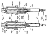
図21〜図26は、本発明の第2の代替自動薬物注入装置アセンブリ30の構造と機能メカニズムを示す。本自動薬物注入装置アセンブリ30において、プレフィルドシリンジ101は、薬物容器として用いられる。一つのプッシュキャップ304は、ダイヤルシリンダ303の径303aを介して自動注射を活性化する。このような接合設計は、装置の使用前における偶発的な活性化を防止することができる。一つの投与量設定窓302aは、下シリンダ302に定義される。計量シリンダ305には、投与量目盛りがマークされる。使用中、ダイヤルシリンダ303を回転させて注射量を設定する。図22に示すように、ユーザは、計量シリンダ305の位置を設定することにより、異なる注射量を設定する。同時に、注射前、自動薬物注入装置アセンブリ30とプッシュロッド309はロック状態であり、プッシュロッド309のフック機構309aとダイヤルシリンダ303による解除可能なラッチロック構造により、駆動スプリング308の付勢力に対抗する。プレフィルドシリンジ101は、そのフランジ機構101bを介して下シリンダ302と一体に組み立てられる。プレフィルドシリンジ101の中の液状薬物は、一つのピストン106と一つの弾性針シェルダ101aにより密封される。図23に示すように、注射前、針シェルダ101aが取り外されると、針先101cが露出する。注射時、プッシュキャップ304は、装置30の遠位端に押される。プッシュキャップ304の遠位端に向くテーパー形状駆動機構304aは、プッシュロッド309のフック機構309aとダイヤルシリンダ303による解除可能なラッチロック構造を解除する。プッシュロッド309は、解除されて、駆動スプリング308の駆動により装置30の遠位端に移動される。ピストン106は、下方向へ押される。プッシュロッド309の円盤機構309bは、計量シリンダ305の着陸面機構305aに止まり、プッシュロッド309の移動を拘束する。すると、プレフィルドシリンジ101の中の液状薬物は、患者の体に注入される。図24は、プッシュロッド309とダイヤルシリンダ303のかみ合いを示す。プッシュロッド309の円盤機構309bの舌機構309baは、ダイヤルシリンダ303の溝機構303aに接合する。ユーザがダイヤルシリンダ303を回転させると、プッシュロッド309は、対応して回転する。図25は、プッシュロッド309と計量シリンダ305とのかみ合いを示す。投与量設定時に、ユーザは、ダイヤルシリンダ303を下シリンダ302に対して回転させる。プッシュロッド309とダイヤルシリンダ303との接続のため、プッシュロッド309は、ダイヤルシリンダ303の回転に追従して回転する。プッシュロッド309が回転すると、計量シリンダ305は、その長方形通路305bとプッシュロッド309の平らな接合面309cとの接合により追従して回転する。計量シリンダ305のねじ機構305cは、下シリンダ302のねじ型キー機構302aに接合する。計量シリンダ305は、回転するとき、下シリンダ302とのねじ接続により、プッシュロッド309の軸方向に沿って上下移動する。計量シリンダ305の位置は、下シリンダ302の観察窓302aから見える。計量シリンダ305の目盛りマーク305dは、投与量を示す。図26は、ダイヤルシリンダ303、計量シリンダ305及び下シリンダ302の接続を示す。投与量設定工程以外の操作工程において、ダイヤルシリンダ303は、その303cと下シリンダ302の302cとの歯結合により常に下シリンダ302にロックされる。投与量設定工程において、ユーザは、ダイヤルシリンダ303を下シリンダ302に対し押下する。次に、303cと302cとの歯状ロックが解除され、ダイヤルシリンダ303が下シリンダ302に対し回転される。投与量設定後、下方向へのスラスト力がなければ、ダイヤルシリンダ303は、上方向へ押され、下シリンダ302の弾性指状機構302bが生じる弾力により、下シリンダ302に再び接合する。ダイヤルシリンダ303の上方向への運動は、そのフランジ機構303bと下シリンダ302のフック機構302dにより停止される。
21-26 illustrate the structure and functional mechanism of a second alternative automatic drug
図27〜図28は、本発明の第3の代替自動薬物注入装置アセンブリ40の構造と機能メカニズムを示す。自動薬物注入装置40の投与量設定メカニズムと活性化メカニズムは、自動薬物注入装置30とは同一である。本自動薬物注入装置アセンブリ40において、一つのプレフィルドカートリッジが薬物容器として用いられる。プレフィルドカートリッジ404は、一つのカートリッジシース402を介して下シリンダ403と一体に組み立てられる。カートリッジシース402の近位端には、下シリンダ403のスナップフィギュア機構403aとの接続に用いられる溝機構402aを有する。カートリッジシース402の遠位端には、ダブルエンドペンニッドル401との接続に用いられるねじ機構402bを有する。
27-28 show the structure and functional mechanism of a third alternative automatic drug
図29〜図34Aは、本発明の第4の代替自動薬物注入装置アセンブリ50の構造と機能メカニズムを示す。自動薬物注入装置50の投与量設定メカニズムと活性化メカニズムは、自動薬物注入装置30とは同一である。本自動薬物注入装置アセンブリ50において、プレフィルドシリンジ211は、薬物容器として用いられる。また、自動薬物注入装置アセンブリ50には、自動針挿入機構が導入される。一つのシリンジハウジング502は、下シリンダ503とともに使用してプレフィルドシリンジ211を載置する。一つの針シェルダプーラ501は、注射前に針シェルダ212と針シェルダシェル213を取り外す。図30は、シリンジハウジング502を示す。シリンジハウジング502には、単方向の湾曲可能な位置決め指502aを有する。位置決め指502aの長さは、プレフィルドシリンジ211から針シェルダ212の除去に必要とする長さより長い。位置決め指502aの近位端502aaは、注射前、プレフィルドシリンジ211のフランジ機構211bを支持する。
29-34A illustrate the structure and functional mechanism of a fourth alternative automatic drug
図31は、自動薬物注入装置50の注射前の各投与量設定を示す。注射前、プレフィルドシリンジ211のフランジ機構211bは、位置決め指502aの近位端502aaに位置する。プレフィルドシリンジ211を注射前に近位端501aaとなるように支持するために、シリンジフランジ211bとシリンジハウジング502の平面502cの間には、オプションである支持スプリング(図示せず)が設置される。プレフィルドシリンジ211が針シェルダ除去中に遠位端へ小さく移動すると、支持スプリングは、プレフィルドシリンジ211を近位端502aaへ戻るように押す。同時に、オプションである支持スプリングによる反作用力が駆動スプリング508による力より小さいため、オプションである支持スプリングは、プレフィルドシリンジ211の遠位端への移動を妨げることがない。図32は、自動薬物注入装置50の注射後の各投与量設定を示す。注射中、駆動スプリング508がピストン210とプレフィルドシリンジ211を装置50の遠位端へ移動するように押すと、プレフィルドシリンジ211のフランジ機構211bは、位置決め指505aの遠位端502abに位置する。注射中、プレフィルドシリンジの筒が注射部位に接触せず、フランジ機構211bの位置決め指502aの遠位端502abへの移動には抵抗力がないからである。
FIG. 31 shows each dose setting before injection of the automatic
図33は、シリンジハウジング502を代替するシリンジハウジング512を示す。シリンジハウジング512は、ロックキー機構512aと指機構512bを有する。シリンジハウジング512は、一つの保護リング513に接合する。注射前、図34に示すように、シリンジハウジング512のロックキー機構512aは、保護リング513の軸方向移動を阻止し、保護リング513の支持指機構513aは、シリンジ211の遠位端への移動を防止する。ユーザは、注射を準備するとき、保護リング513を解除位置に回転させる。解除位置において、保護リングは、遠位端への移動が可能である。図34Aに示すように、注射後、シリンジ211と保護リング513の両方が遠位端へ移動し、シリンジ211の位置が指機構512bにより定められる。
FIG. 33 shows a
図35〜図39は、本発明の第5の代替自動薬物注入装置アセンブリ60の構造と機能メカニズムを示す。本実施例の自動薬物注入装置アセンブリ60において、一つのシリンジ601は、薬物容器として、ガラス製又はプラスチック製である。一つの針シェルダ(又は針キャップ)601aは、シリンジ601の遠位端に設置される。一つのボタン603は、自動注射の活性化に用いられる。ボタン603は、コネクタ602に接合する。図36に示すように、ユーザは、まず針シェルダ601aを取り外し、次に近位端へプッシュロッド604を引き寄せ、薬物を小瓶650からシリンジ601へ流入させる。図37〜図37Cに示すように、コネクタ602は、シリンジ601のフランジ機構601bを介してシリンジ601に組み立てられる。注射前、駆動スプリング605は、伸展段階にあり、ピストン606は、自動薬物注入装置60の遠位端に位置する。薬物をシリンジ601に導入するために、ユーザは、プッシュロッド604の指握りフランジ機構604aを介して、装置60の近位端にプッシュロッド604を引き寄せる。ピストン606も対応して自動薬物注入装置60の近位端に移動する。コネクタ602の遮断機構602aは、プッシュロッド604の一連の歯機構604bとかみ合いし、プッシュロッド604が駆動スプリング605により装置60の遠位端に押されることを防止する。プッシュロッド604の歯機構604aは、異なる注射量の設定に用いられる。プッシュロッド604には、投与量設定をしやすくするために投与量マークを設置してもよい。注射時、ボタン603は、内側へ押されてプッシュロッド604に押されて、コネクタ602の遮断機構602aが対応して外側へ押されてプッシュロッド604から離れる(図38Bに示す)。遮断機構602aと歯機構602bとの接合が解除される。次に、プッシュロッド604が解除され、ピストン605は、プッシュロット604を装置60の遠位端に押す。ピストン606は、下方向へ押される。すると、シリンジ601の中の液状薬物は、患者の体内に注射される。図38と図39は、プッシュロッド604、コネクタ602、ボタン603のかみ合いを示す。注射前、プッシュロッド604の歯機構604bは、コネクタ602の遮断機構602aに接合する。コネクタ602の湾曲可能な指機構602bにより、プッシュロッド604に対して外側へボタン603に付勢する。図39に示すように、注射時、ユーザは、プッシュロッド604方向へボタン603を押圧する。ボタン603の一つの平面機構603aは、コネクタ602の遮断機構602aを外側へ押し、プッシュロッド604を解除する。
35-39 show the structure and functional mechanism of a fifth alternative automatic drug
図40と図41は、本発明の第6の代替自動薬物注入装置アセンブリ70の構造と機能メカニズムを示す。自動薬物注入装置70の投与量設定メカニズムと活性化メカニズムは、自動薬物注入装置60とは同一である。本自動薬物注入装置アセンブリ70において、一つのルアーロックシリンジ701は、薬物容器として用いられる。ルアーロックシリンジ701は、コネクタ602と一体に組み立てられる。ルアーロックシリンジの遠位端には、一つのルアーロック針702が接続される。
40 and 41 show the structure and functional mechanism of a sixth alternative automatic drug
図42〜図45は、本発明の第7の代替自動薬物注入装置アセンブリ80の構造と機能メカニズムを示す。自動薬物注入装置80の活性化メカニズムは、自動薬物注入装置60とは同一である。本自動薬物注入装置アセンブリ80において、プレフィルドシリンジ211は、薬物容器として用いられる。ハウジング803は、プレフィルドシリンジ211を載置するために用いられる。一つのキャップ807は、ハウジング803の遠位端に設置される。異なる注射量設定をしやすくするために、一つの投与量設定リング805が導入される。図42に示すように、注射前、ユーザは、ハウジング803の投与量設定領域803aに沿って投与量設定リング805を移動する。一つの針シェルダプーラ804は、注射前に針シェルダ211と針シェルダシェル213を取り外すために用いられる。図43〜図45に示すように、注射時、ユーザは、内側へボタン603を押圧する。プッシュロッド806とコネクタ802によるロック構造は、解除される。駆動スプリング809は、プッシュロッド806を自動薬物注入装置80の遠位端に押す。プッシュロッド806の運動は、そのフランジ機構806aが投与量設定リング805に当接すると停止する。フランジ機構806aのリブ機構806aaは、リング805の歯機構805aに接合し、投与量設定リング805のそれ以上の回転を防止する。投与量設定リング805を異なる位置にすることにより、異なる注射量を設定することができる。また、装置80には自動針挿入メカニズムが導入される。駆動スプリングは、プッシュロッド806、ピストン210及びプレフィルドシリンジ211を自動薬物注入装置80の遠位端へ押す。一つのシリンジ支持スプリング808は、圧縮される。一つの湾曲可能な指機構(断面図には隠される)は、シリンジ支持スプリング808の圧縮後にプレフィルドシリンジ211の位置をロックするために用いられる。前記指機構は、自動薬物注入装置50に示されるものとは同一である。又は、図33〜図34Aに示される設計メカニズムは、装置80に実施されてもよい。
42-45 show the structure and functional mechanism of a seventh alternative automatic drug
図46と図47は、本発明の第7の代替自動薬物注入装置アセンブリ80の代替アセンブルを示す。本代替アセンブリにおいて、投与量設定リング805は、プッシュロッド806のフランジ機構806aより近位端に位置する。この場合、投与量設定リング805は、最大注射量の事前設定に用いられる。
46 and 47 show an alternative assembly of the seventh alternative automatic drug
図48は、投与量設定リング805がハウジング803のねじ機構803bを介してハウジング803とかみ合うことを示す。
FIG. 48 shows that the
図49と図50は、本発明の第8の代替自動薬物注入装置アセンブリ90の構造と機能メカニズムを示す。自動薬物注入装置90の投与量設定メカニズムと活性化メカニズムは、自動薬物注入装置80とは同一である。本自動薬物注入装置90は、針シェルダ212と針シェルダシェル213ではなく、圧縮可能な針シェルダサブアセンブリ904を使用する。ハウジング903は、圧縮可能な針シェルダサブアセンブリ904を載置するために用いられる。圧縮可能な針シェルダサブアセンブリ904は、圧縮可能部品904a、剛性針シェルダフレーム904b、弾性針シェルダ904cからなる。注射時、自動薬物注入装置90は、患者の注射部位の皮膚に押し当てられる。圧縮可能部品904aは、崩れる。針先211aは、弾性針シェルダ904cを刺し通して患者の皮膚に差し込む。前記設計において、注射前のユーザによる針シェルダ手動除去工程をスキップすることができる。前記設計により、プレフィルドシリンジ211内は予め真空に設定される。
49 and 50 show the structure and functional mechanism of the eighth alternative automatic drug
図51〜図55は、本発明の第9の代替自動薬物注入装置アセンブリ100の構造と機能メカニズムを示す。本実施例の自動薬物注入装置100において、一つのシリンジ601は、薬物容器として、ガラス製又はプラスチック製である。一つのボタン1002は、自動注射の活性化に用いられる。ボタン1002は、コネクタ1001とかみ合う。コネクタ1001は、一つのキャップアセンブリ1004に覆われる。図53〜図53Bに示すように、ユーザは、まず針シェルダ601aを取り外す。次に、ユーザは、自動薬物注入装置100の遠位端へプッシュロッド1003のフランジ機構1003aを引き寄せ、薬物をシリンジ601に流入させる。プッシュロッド1003が自動薬物注入装置100の近位端に引き寄せると、歯機構1003bは、駆動歯車1005の歯車機構1005aとかみ合い、駆動歯車1005を回転させる。駆動歯車1005の回転により、トーションスプリング1006には張力トルクが生じる。図53〜図53Bに示すように、コネクタ1001は、シリンジ601のフランジ機構601bを介してシリンジ601と一体に組み立てられる。注射前、トーションスプリング1006(図51〜図51Bでは隠される)は、ルーズ状態にあり、ピストン606は、自動薬物注入装置100の遠位端に位置する。薬物をシリンジ601に誘導するとき、ピストン606は、対応して自動薬物注入装置100の遠位端に移動する。同時に、トーションスプリング1006は、引き締められる。コネクタ1001の遮断機構1001aと駆動歯車1005のラチェット機構1005bとの接合により、プッシュロッド1003がトーションスプリング1006による駆動で自動薬物注入装置100の遠位端へ移動することを阻止する。プッシュロッド1003のフランジ機構1003aは、異なる投与量の設定に用いられる。注射時、ボタン1002は、自動薬物注入装置100の遠位端に押される。ボタン1002の斜面機構1002aにより、コネクタ1001の遮断機構1001aは、対応して駆動歯車1005のラチェット機構1005bから押し離され、プッシュロッド1003が解除される。
51-55 show the structure and functional mechanism of a ninth alternative automatic drug
図54と図55は、遮断機構1001aとラチェット機構1005bとのかみ合いの詳細を示す。プッシュロッド1003が解除されると、トーションスプリング1006は、駆動歯車1005を介してプッシュロッド1003を装置100の遠位端へ押す。ピストン606は、下方向へ押される。すると、シリンジ601の中の液状薬物は、患者の体内に注入される。
54 and 55 show details of the engagement between the
図56〜図59は、本発明の第10の代替自動薬物注入装置アセンブリ110の構造と機能メカニズムを示す。自動薬物注入装置110の活性化メカニズムは、自動薬物注入装置100とは同一である。本自動薬物注入装置アセンブリ110において、プレフィルドシリンジ211は、薬物容器として用いられる。一つのハウジング1108は、プレフィルドシリンジ211を載置するために用いられる。一つのキャップ104は、コネクタ1101と一体に組み立てられる。一つの投与量設定タブ1107は、異なる注射量を設定するために導入される。注射前、ユーザは、キャップ1104の投与量設定領域1104aに沿って投与量設定タブ1107を移動する。図56と図57は、投与量設定タブ1107が異なる位置に置かれて異なる注射量設定が達成されることを示す。一つの針シェルダプーラ1106は、注射前に針シェルダ212と針シェルダシェル213を取り外すために用いられる。注射中、ユーザは、ボタン1102を押下して自動薬物注入装置110を活性化する。プッシュロッド1103とコネクタ1101によるロック機構が解除される。トーションスプリング1106(隠される)は、駆動スプリング1105を回転させる。駆動スプリング1105の回転により、プッシュロッド1103の歯機構1103aを介してプッシュロッド1103の自動薬物注入装置110の遠位端への移動を引き起こす。プッシュロッド1103の移動は、そのフランジ機構1103bが投与量設定タブ1107に当接すると(図59を参照する)停止する。異なる注射量は、投与量設定タブ1107を異なる位置にすることにより実現される。また、一つの自動針挿入機構が導入される。トーションスプリング106は、プッシュロッド1103、ピストン210及びプレフィルドシリンジ211を自動薬物注入装置110の遠位端へ移動するように押す。シリンジ支持スプリング1109は、圧縮される。一つの自動薬物注入装置50に示すものとは同一である湾曲可能な指機構(断面図では隠される)は、シリンジ支持スプリング1109の圧縮後にプレフィルドシリンジ211の位置をロックするために用いられる。又は、図33〜図34Aに示す設計構造は、装置80に実施されてもよい。
56-59 show the structure and functional mechanism of a tenth alternative automatic drug
図60は、本発明の第10の代替自動薬物注入装置アセンブル110の代替形態である。本代替形態において、投与量設定タブ1107は、プッシュロッド1103のフランジ機構1103bより近位端に位置する。この場合、投与量設定タブ1107は、最大注射量の事前設定に用いられる。
FIG. 60 is an alternative form of the tenth alternative automatic drug
上述の実施形態において、自動薬物注入装置10、20、30、40、50、80及び110の投与量設定は、双方向に行われる。
In the above-described embodiment, the dosage setting of the automatic
全ての上記実施例における特徴と設計理念は、ここで変更又は互いに組み合わせることにより、新しい設備の実施形態が生じる。当業者は、装置、方法及び/又はシステム、並びにここで記載した実施例の各構成への修正(追加及び/又は削除)について、本発明の全範囲と思想から逸脱しない限り、このような修正といかなる同等設計が本発明に含まれると理解できる。 The features and design philosophies in all the above embodiments can now be changed or combined with each other, resulting in new equipment embodiments. Those skilled in the art will appreciate that modifications (additions and / or deletions) to the configurations of the devices, methods and / or systems and embodiments described herein are within the scope and spirit of the present invention. It can be understood that any equivalent design is included in the present invention.
10 自動薬物注入装置アセンブリ
101 プレフィルドシリンジ
101a (プレフィルドシリンジ101の)針シェルダ(針シールド)
101b (プレフィルドシリンジ101の)フランジ機構
101c (プレフィルドシリンジ101の)針先
102 計量シリンダ
102a (計量シリンダ102の)投与量設定窓(着陸機構)
102c (計量シリンダ102の)軌道機構
102d (計量シリンダ102の)歯状ロック
103 ダイヤルシリンダ
103a (ダイヤルシリンダ103の)軌道
103b (ダイヤルシリンダ103の)長方形通路機構
103c (ダイヤルシリンダ103の)ロック構造
104 プッシュキャップ
104a (プッシュキャップ104の)テーパー形状駆動機構
105 プッシュロッド
105a (プッシュロッド105の)フック機構
105b (プッシュロッド105の)平面
105c (プッシュロッド105の)ねじ機構
106 ピストン
107 駆動スプリング
108 ストップリング
108a (ストップリング108の)溝機構
109 分離スプリング
20 第1の代替自動薬物注入装置アセンブリ
201 ダイヤルキャップ
201a (ダイヤルキャップ201の)リブ機構
202 プッシュキャップ
202a (プッシュキャップ202の遠位端に向く)テーパー形状駆動機構
203 ダイヤルシリンダ
203a (ダイヤルシリンダ203の)開口溝機構
203b (ダイヤルシリンダ203の)長方形通路
204 ロックキー
204a (ロックキー204の)キー機構
204b (ロックキー204の)足機構
205 分離スプリング
206 プッシュロッド
206a (プッシュロッド206の)フック機構
206b (プッシュロッド206の)平面
207 伸展シース
208 駆動スプリング
209 ストップリング
210 ピストン
211 プレフィルドシリンジ
211a (プレフィルドシリンジ211の)針先
211b (プレフィルドシリンジ211の)フランジ機構
212 弾性針シェルダ
213 針シェルダシェル
214 シリンジスプリング
215 計量シリンダ
215a (計量シリンダ215の)投与量設定領域
215a (計量シリンダ215の)溝機構
216 下シリンダ
216a (下シリンダ216の)観察窓
216b (下シリンダ216の)着陸面機構(キー機構)
217 針保護シェルダ
217a (針保護シェルダ217の)平面機構
217b (針保護シェルダ217の)軌道機構
217c (針保護シェルダ217の)ブロック機構
218 針シェルダプーラ
30 自動薬物注入装置アセンブリ
302 下シリンダ
302a (下シリンダ302の)投与量設定窓(ねじ型キー機構)
302b (下シリンダ302の)弾性指状機構
302c (下シリンダ302の)歯
302d (下シリンダ302の)フック機構
303 ダイヤルシリンダ
303a (ダイヤルシリンダ303の)径(溝機構)
303b (ダイヤルシリンダ303の)フランジ機構
304 プッシュキャップ
304a (プッシュキャップ304の遠位端に向く)テーパー形状駆動機構
305 計量シリンダ
305a (計量シリンダ305の)着陸面機構
305b (計量シリンダ305の)長方形通路
305c (計量シリンダ305の)ねじ機構
305d (計量シリンダ305の)目盛りマーク
308 駆動スプリング
309 プッシュロッド
309a (プッシュロッド309の)フック機構
309b (プッシュロッド309の)円盤機構
309ba (プッシュロッド309の円盤機構309bの)舌機構
309c (プッシュロッド309の)平らな接合面
40 第3の代替自動薬物注入装置アセンブリ
401 ダブルエンドペンニッドル
402 カートリッジシース
402a (カートリッジシース402の)溝機構
402b (カートリッジシース402の)ねじ機構
403 下シリンダ
403a (下シリンダ403の)スナップフィギュア機構
404 プレフィルドカートリッジ
50 第4の代替自動薬物注入装置アセンブリ
501 針シェルダプーラ
501aa 近位端
502 シリンジハウジング
502a (シリンジハウジング502の)位置決め指
502aa (シリンジハウジング502における位置決め指502aの)近位端
502ab (シリンジハウジング502における位置決め指502aの)遠位端
502c (シリンジハウジング502の)平面
503 下シリンダ
508 駆動スプリング
512 (代替の)シリンジハウジング
512a (シリンジハウジング512の)ロックキー機構
512b (シリンジハウジング512の)指機構
513 保護リング
513a (保護リング513の)支持指機構
60 第5の代替自動薬物注入装置アセンブリ
601 シリンジ
601a 針シェルダ(又は針キャップ)
601b (シリンジ601の)フランジ機構
602 コネクタ
602a (コネクタ602の)遮断機構
602b (コネクタ602の)歯機構(かつ、湾曲可能な指機構)
603 ボタン
603a (ボタン603の)平面機構
604 プッシュロッド
604a (プッシュロッド604の)歯機構
604b (プッシュロッド604の)歯機構
605 駆動スプリング
606 ピストン
650 小瓶
70 第6の代替自動薬物注入装置アセンブリ
701 ルアーロックシリンジ
702 ルアーロック針
80 第7の代替自動薬物注入装置アセンブリ
802 コネクタ
803 ハウジング
803a (ハウジング803の)投与量設定領域
803b (ハウジング803の)ねじ機構
804 針シェルダプーラ
805 投与量設定リング
805a (投与量設定リング805の)歯機構
806 プッシュロッド
806a (プッシュロッド806の)フランジ機構
806aa (プッシュロッド806のフランジ機構806aの)リブ機構
807 キャップ
808 シリンジ支持スプリング
809 駆動スプリング
90 第8の代替自動薬物注入装置アセンブリ
903 ハウジング
904 針シェルダサブアセンブリ
904a (針シェルダサブアセンブリ904の)圧縮可能部品
904b (針シェルダサブアセンブリ904の)剛性針シェルダフレーム
904c (針シェルダサブアセンブリ904の)弾性針シェルダ
100 第9の代替自動薬物注入装置アセンブリ
1001 コネクタ
1001a (コネクタ1001の)遮断機構
1002 ボタン
1002a (ボタン1002の)斜面機構
1003 プッシュロッド
1003a (プッシュロッド1003の)フランジ機構
1003b (プッシュロッド1003の)歯機構
1004 キャップアセンブリ
1005 駆動歯車
1005a (駆動歯車1005の)歯車機構
1005b (駆動歯車1005の)ラチェット機構
1006 トーションスプリング
110 第10の代替自動薬物注入装置アセンブリ
1101 コネクタ
1102 ボタン
1103 プッシュロッド
1103a (プッシュロッド1103の)歯機構
1103b (プッシュロッド1103の)フランジ機構
1104 キャップ
1104a (キャップ1104の)投与量設定領域
1105 駆動スプリング
1106 針シェルダプーラ
1107 投与量設定タブ
1108 ハウジング
1109 シリンジ支持スプリング
DESCRIPTION OF
101b Flange mechanism (of prefilled syringe 101) 101c Needle tip (of prefilled syringe 101) 102
102c Orbit mechanism (of measuring cylinder 102) 102d Tooth-like lock (of measuring cylinder 102) 103 Dial cylinder 103a Orbit 103b (of dial cylinder 103) Rectangular passage mechanism 103c (of dial cylinder 103) Lock structure 104 Push cap 104a Taper shaped drive mechanism (of push cap 104) 105 Push rod 105a Hook mechanism (of push rod 105) 105b Flat surface (of push rod 105) 105c Screw mechanism (of push rod 105) 106 Piston 107 Drive spring 108 Stop ring 108a Groove mechanism (of stop ring 108) 109 Separation spring 20 First alternative automatic drug infusion device assembly 201 Dial cap 2 1a Rib mechanism (of the dial cap 201) 202 Push cap 202a Taper-shaped drive mechanism (facing the distal end of the push cap 202) 203 Dial cylinder 203a (Dial cylinder 203) Opening groove mechanism 203b (Dial cylinder 203) rectangular passage 204 Lock key 204a (Lock key 204) Key mechanism 204b (Lock key 204) Foot mechanism 205 Separating spring 206 Push rod 206a (Push rod 206) Hook mechanism 206b (Push rod 206) Planar 207 Extension sheath 208 Drive spring 209 Stop ring 210 Piston 211 Prefilled syringe 211a Needle tip 211b (of prefilled syringe 211) Hula (of prefilled syringe 211) Needle mechanism 212 elastic needle sheller 213 needle sheller shell 214 syringe spring 215 metering cylinder 215a (dose cylinder 215) dose setting area 215a (measuring cylinder 215) groove mechanism 216 lower cylinder 216a (lower cylinder 216) observation window 216b ( Landing surface mechanism (key mechanism) of lower cylinder 216
217
302b Elastic finger mechanism (of the lower cylinder 302) 302c Teeth of the
303b Flange mechanism (of the dial cylinder 303) 304 Push cap 304a Taper shaped drive mechanism (toward the distal end of the push cap 304) 305 Measuring cylinder 305a Landing surface mechanism 305b (of the measuring cylinder 305) Rectangular passage 305c (Measuring cylinder 305) screw mechanism 305d (Measuring cylinder 305) scale mark 308 Drive spring 309 Push rod 309a (Push rod 309) Hook mechanism 309b (Push rod 309) Disk mechanism 309ba (Push rod 309 disk mechanism) 309b) tongue mechanism 309c (push rod 309) flat interface 40 third alternative automatic drug infusion device assembly 401 double end penddle 402 cartridge 402a Groove mechanism (of cartridge sheath 402) 402b Screw mechanism (of cartridge sheath 402) 403 Lower cylinder 403a Snap figure mechanism (of lower cylinder 403) 404 Prefilled cartridge 50 Fourth alternative automatic drug infusion device assembly 501 Needle shell double puller 501aa Proximal end 502 Syringe housing 502a Positioning finger 502aa (of positioning finger 502a in syringe housing 502) Proximal end 502ab (of positioning finger 502a in syringe housing 502) Distal end 502c (of syringe housing 502) Plane 503 Lower cylinder 508 Drive spring 512 (Alternative) Syringe housing 512a (Syringe housing 512) lock Over mechanism 512b (syringe housing 512) (the protection ring 513) finger mechanism 513 protection ring 513a supporting finger mechanism 60 fifth alternative automatic drug infusion device assembly 601 syringe 601a needle Sheruda (or needle cap)
601b (Syringe 601)
603 Button 603a Plane mechanism (of button 603) 604 Push rod 604a Tooth mechanism (of push rod 604) Tooth mechanism 604b Tooth mechanism (of push rod 604) 605 Drive spring 606 Piston 650 Small bottle 70 Sixth alternative automatic drug injection device assembly 701 Luer Lock syringe 702 Luer lock needle 80 Seventh alternative automatic drug infusion device assembly 802 Connector 803 Housing 803a Dose setting area 803b (Housing 803) Screw mechanism 804 Needle shell doubler 805 Dose setting ring 805a (Dose) Tooth mechanism of setting ring 805 806 Push rod 806a Flange mechanism of push rod 806 806aa (of flange mechanism 806a of push rod 806) Rib mechanism 807 Cap 808 Syringe support spring 809 Drive spring 90 Eighth alternative automatic drug infusion device assembly 903 Housing 904 Needle shell subassembly 904a Compressible part 904b (needle shell subassembly 904) ) Rigid needle sherder frame 904c elastic needle sheller (of needle sheller subassembly 904) 100th alternative automatic drug infusion device assembly 1001 connector 1001a (of connector 1001) blocking mechanism 1002 button 1002a (of button 1002) slope mechanism 1003 Push rod 1003a Flange mechanism (of push rod 1003) 1003b Teeth mechanism (of push rod 1003) 1004 Cap assembly 1005 Drive Wheel 1005a (Driving gear 1005) Gear mechanism 1005b (Driving gear 1005) Ratchet mechanism 1006 Torsion spring 110 Tenth alternative automatic drug injection device assembly 1101 Connector 1102 Button 1103 Push rod 1103a (Push rod 1103) Tooth mechanism 1103b ( Flange mechanism (of push rod 1103) 1104 Cap 1104a Dose setting area (of cap 1104) 1105 Driving spring 1106 Needle shell puller 1107 Dose setting tab 1108 Housing 1109 Syringe support spring
Claims (11)
前記容器本体の少なくとも一部に対し移動可能であるプッシュロッドと、
前記プッシュロッドを前記容器本体の遠位端に向けて移動するように付勢するように構成された弾性部材と、
前記弾性部材の付勢に抗してロック状態になるように前記プッシュロッドを解除可能に拘束する解除可能な拘束手段であって、前記解除可能な拘束手段が解除された場合、前記プッシュロッドが前記弾性部材の弾性力により前記容器本体の前記遠位端に向けて移動するように設計されている解除可能な拘束手段と、
前記解除可能な拘束手段が解除された場合、予め定められた薬剤投与量を送達するべく、前記プッシュロッドの前記容器本体に対する移動量を調整する手段であって、
前記プッシュロッドの軸方向に沿って双方向的に往復移動可能であるストップリング、および、前記プッシュロッドの軸方向に沿って前記ストップリングの位置を調整するダイヤルシリンダを備えてなる、プッシュロッドの移動量を調整する手段と、
前記解除可能な拘束手段を解除するように構成された活性化手段と、
薬剤送達時に前記プッシュロッドの回転を抑制するための機械的構造と、
を備えてなる薬剤送達装置。 In a drug delivery device for use with a container body having a distal end and a needle installed at the distal end of said container body,
A push rod movable relative to at least a portion of the container body;
An elastic member configured to bias the push rod to move toward the distal end of the container body;
A releasable restraining means for releasably restraining the push rod so as to be in a locked state against an urging force of the elastic member, and when the releasable restraining means is released, the push rod is Releasable restraining means designed to move toward the distal end of the container body by the elastic force of the elastic member;
Means for adjusting the amount of movement of the push rod relative to the container body to deliver a predetermined drug dose when the releasable restraining means is released ,
A push ring comprising: a stop ring that is capable of bidirectional reciprocation along the axial direction of the push rod; and a dial cylinder that adjusts the position of the stop ring along the axial direction of the push rod. Means for adjusting the amount of movement;
Activating means configured to release the releasable restraining means;
A mechanical structure for suppressing rotation of the push rod during drug delivery;
A drug delivery device comprising:
前記プッシュロッド(105)の回転を抑制するための機械的構造は、The mechanical structure for suppressing the rotation of the push rod (105) is:
相互拘束をもたらすところの、前記ストップリング(108)の溝機構(108a)および前記計量シリンダ(102)の軌道機構(102c)、並びに、A groove mechanism (108a) of the stop ring (108) and a trajectory mechanism (102c) of the measuring cylinder (102), which cause mutual restraint, and
前記ダイヤルシリンダ(103)の歯(103c)および前記計量シリンダ(102)の歯(102d)Teeth (103c) of the dial cylinder (103) and teeth (102d) of the measuring cylinder (102)
によって構成され、Composed by
前記ダイヤルシリンダ(103)の歯(103c)と前記計量シリンダ(102)の歯(102d)との間のロック用の歯状噛み合いは、薬剤送達時に前記プッシュロッド(105)の回転を抑制する、ことを特徴とする請求項1に記載の薬剤送達装置。The tooth engagement for locking between the teeth (103c) of the dial cylinder (103) and the teeth (102d) of the measuring cylinder (102) suppresses the rotation of the push rod (105) during drug delivery. The drug delivery device according to claim 1.
前記ダイヤルシリンダ(203)内に配置されるロックキー(204)と、A lock key (204) disposed in the dial cylinder (203);
を更に備えており、Is further provided,
前記プッシュロッド(206)の回転を抑制するための機械的構造は、The mechanical structure for suppressing the rotation of the push rod (206) is:
相互拘束をもたらすところの、前記ストップリング(209)の溝機構(209a)および前記計量シリンダ(215)の軌道機構(215b)、並びに、前記ロックキー(204)によって構成され、Constituted by a groove mechanism (209a) of the stop ring (209) and a track mechanism (215b) of the measuring cylinder (215), and the lock key (204), which cause mutual restraint,
前記ロックキー(204)は、薬剤送達時に前記プッシュロッド(206)の回転を抑制する、ことを特徴とする請求項1に記載の薬剤送達装置。The drug delivery device according to claim 1, wherein the lock key (204) suppresses rotation of the push rod (206) during drug delivery.
Applications Claiming Priority (5)
| Application Number | Priority Date | Filing Date | Title |
|---|---|---|---|
| US201462046191P | 2014-09-05 | 2014-09-05 | |
| US62/046,191 | 2014-09-05 | ||
| US201562155509P | 2015-05-01 | 2015-05-01 | |
| US62/155,509 | 2015-05-01 | ||
| PCT/US2015/047477 WO2016036600A1 (en) | 2014-09-05 | 2015-08-28 | Automatic injection device with variable dosing |
Publications (3)
| Publication Number | Publication Date |
|---|---|
| JP2017525466A JP2017525466A (en) | 2017-09-07 |
| JP2017525466A5 JP2017525466A5 (en) | 2018-08-02 |
| JP6449990B2 true JP6449990B2 (en) | 2019-01-09 |
Family
ID=55440281
Family Applications (1)
| Application Number | Title | Priority Date | Filing Date |
|---|---|---|---|
| JP2017509710A Active JP6449990B2 (en) | 2014-09-05 | 2015-08-28 | Automatic drug delivery device |
Country Status (5)
| Country | Link |
|---|---|
| US (2) | US10603444B2 (en) |
| EP (1) | EP3188772B1 (en) |
| JP (1) | JP6449990B2 (en) |
| CN (1) | CN107073199B (en) |
| WO (1) | WO2016036600A1 (en) |
Families Citing this family (9)
| Publication number | Priority date | Publication date | Assignee | Title |
|---|---|---|---|---|
| US11633540B2 (en) * | 2017-12-04 | 2023-04-25 | Novo Nordisk A/S | Spring straining mechanism for torsion spring based device |
| WO2020008381A1 (en) * | 2018-07-06 | 2020-01-09 | Zekhnareh Mohsen | Secure syringe click lock preventing needle release and drug leakage |
| TWI670097B (en) * | 2018-10-24 | 2019-09-01 | 群康生技股份有限公司 | Syringe with injection dose adjustment |
| US11744951B2 (en) | 2018-10-24 | 2023-09-05 | Cc Biotechnology Corporation | Syringe with injection dose adjustment function |
| CN109772218B (en) * | 2018-12-30 | 2021-06-22 | 浙江省海洋水产研究所 | Quantitative reagent injection device |
| CN110141728B (en) * | 2019-05-10 | 2020-12-22 | 江苏德尔福医疗器械有限公司 | Injection pen cap convenient for injection |
| CN111407977B (en) * | 2020-04-08 | 2022-10-21 | 北京航宇阳光机电技术研究所 | Automatic injection device |
| USD936218S1 (en) * | 2020-06-04 | 2021-11-16 | Ultradent Products, Inc. | Unit dose container |
| CH717905A2 (en) * | 2020-09-30 | 2022-03-31 | Ypsomed Ag | Auto-injector with pouring stop. |
Family Cites Families (14)
| Publication number | Priority date | Publication date | Assignee | Title |
|---|---|---|---|---|
| FR2539302B1 (en) * | 1983-01-17 | 1986-03-14 | Brunet Jean Louis | SYRINGE FOR MEDICAL USE |
| GB9100819D0 (en) * | 1991-01-15 | 1991-02-27 | Medimech Int Ltd | Subcutaneous injector |
| ATE121953T1 (en) * | 1991-07-24 | 1995-05-15 | Medico Dev Investment Co | INJECTOR. |
| US5514097A (en) * | 1994-02-14 | 1996-05-07 | Genentech, Inc. | Self administered injection pen apparatus and method |
| JP2005000203A (en) * | 2003-06-09 | 2005-01-06 | Nemoto Kyorindo:Kk | Liquid medication injection system |
| GB2410188B (en) * | 2004-01-23 | 2006-01-25 | Medical House Plc | Injection device |
| AU2005298944B2 (en) * | 2004-10-21 | 2010-12-23 | Novo Nordisk A/S | Dial-down mechanism for wind-up pen |
| US20070265568A1 (en) * | 2004-11-04 | 2007-11-15 | Izrail Tsals | Automatic Injector |
| GB2433032A (en) * | 2005-12-08 | 2007-06-13 | Owen Mumford Ltd | Syringe with dose adjustment means |
| DK2023982T3 (en) * | 2006-05-18 | 2012-10-01 | Novo Nordisk As | Injection device with mode locking means |
| WO2010033790A2 (en) * | 2008-09-18 | 2010-03-25 | Becton, Dickinson And Company | Medical injector with rotatable body portions |
| GB2467904B (en) * | 2009-02-17 | 2013-06-12 | Oval Medical Technologies Ltd | Drug container and delivery mechanism |
| ES2574057T3 (en) * | 2009-12-15 | 2016-06-14 | Shl Group Ab | Medication delivery device |
| PL2753384T3 (en) * | 2011-09-09 | 2018-11-30 | Merck Patent Gmbh | An auto-injector for epinephrine injection |
-
2015
- 2015-08-28 JP JP2017509710A patent/JP6449990B2/en active Active
- 2015-08-28 US US15/503,389 patent/US10603444B2/en active Active
- 2015-08-28 WO PCT/US2015/047477 patent/WO2016036600A1/en active Application Filing
- 2015-08-28 CN CN201580045106.6A patent/CN107073199B/en active Active
- 2015-08-28 EP EP15837941.2A patent/EP3188772B1/en active Active
-
2020
- 2020-02-09 US US16/785,618 patent/US11065391B2/en active Active
Also Published As
| Publication number | Publication date |
|---|---|
| US10603444B2 (en) | 2020-03-31 |
| EP3188772A4 (en) | 2018-08-01 |
| CN107073199B (en) | 2020-08-18 |
| WO2016036600A1 (en) | 2016-03-10 |
| US20170239424A1 (en) | 2017-08-24 |
| US11065391B2 (en) | 2021-07-20 |
| JP2017525466A (en) | 2017-09-07 |
| US20200171247A1 (en) | 2020-06-04 |
| EP3188772B1 (en) | 2024-06-05 |
| EP3188772A1 (en) | 2017-07-12 |
| CN107073199A (en) | 2017-08-18 |
Similar Documents
| Publication | Publication Date | Title |
|---|---|---|
| JP6449990B2 (en) | Automatic drug delivery device | |
| JP6219353B2 (en) | Palm-operated drug delivery device | |
| US10661020B2 (en) | Medication delivery device | |
| US6966899B2 (en) | Hand-piece for injection device with a retractable and rotating needle | |
| JP5600115B2 (en) | Drug delivery system to increase lever and gear force for high pressure injection system | |
| US6830562B2 (en) | Injector device for placing a subcutaneous infusion set | |
| US10881796B2 (en) | Automatic medication injection device | |
| JP2017525466A5 (en) | ||
| US20100030155A1 (en) | Cannula and Delivery Device | |
| JP6301654B2 (en) | Automatic syringe | |
| JP2007521845A (en) | Injection device with needle cover | |
| JPH0763507B2 (en) | Injection needle structure | |
| TW201404419A (en) | Drive control mechanisms and automatic injectors for injectable cartridges | |
| US10556067B2 (en) | Automatic injection device for multiple dosing | |
| RU2683394C1 (en) | Devices for directed delivery of therapeutic implants | |
| US20240033446A1 (en) | Fluid delivery system with needle assembly | |
| US20140257195A1 (en) | Medical Injection System Comprising a Medical Injection Device and a Dose Limiter Module | |
| US20240033445A1 (en) | Fluid delivery system with needle assembly | |
| CA2499402C (en) | Injection applicator for a hypodermic syringe | |
| CN108379698A (en) | Syringe drive device | |
| JP2002272842A (en) | Syringe auxiliary tool | |
| EA040210B1 (en) | DRUG DELIVERY DEVICE ACTIVATED WITH THE PALM OF THE HAND | |
| EA043488B1 (en) | PALM ACTUATED DRUG DELIVERY DEVICE |
Legal Events
| Date | Code | Title | Description |
|---|---|---|---|
| A621 | Written request for application examination |
Free format text: JAPANESE INTERMEDIATE CODE: A621 Effective date: 20170414 |
|
| A977 | Report on retrieval |
Free format text: JAPANESE INTERMEDIATE CODE: A971007 Effective date: 20180228 |
|
| A131 | Notification of reasons for refusal |
Free format text: JAPANESE INTERMEDIATE CODE: A131 Effective date: 20180306 |
|
| A601 | Written request for extension of time |
Free format text: JAPANESE INTERMEDIATE CODE: A601 Effective date: 20180531 |
|
| A521 | Request for written amendment filed |
Free format text: JAPANESE INTERMEDIATE CODE: A523 Effective date: 20180613 |
|
| A524 | Written submission of copy of amendment under article 19 pct |
Free format text: JAPANESE INTERMEDIATE CODE: A524 Effective date: 20180613 |
|
| A521 | Request for written amendment filed |
Free format text: JAPANESE INTERMEDIATE CODE: A821 Effective date: 20180613 |
|
| TRDD | Decision of grant or rejection written | ||
| A01 | Written decision to grant a patent or to grant a registration (utility model) |
Free format text: JAPANESE INTERMEDIATE CODE: A01 Effective date: 20181113 |
|
| A61 | First payment of annual fees (during grant procedure) |
Free format text: JAPANESE INTERMEDIATE CODE: A61 Effective date: 20181206 |
|
| R150 | Certificate of patent or registration of utility model |
Ref document number: 6449990 Country of ref document: JP Free format text: JAPANESE INTERMEDIATE CODE: R150 |
|
| R250 | Receipt of annual fees |
Free format text: JAPANESE INTERMEDIATE CODE: R250 |